Improved RAS functions Reduced maintenance Space saving High performance and advanced functions LV1HM : 200 V, 0.4 kW to 22 kW 400 V, 0.4 kW to 45 kW LV1HF : 400 V, 55 kW to 185 kW LV1HS : 400 V, 200 kW to 1000 kW 690 V, 350 kW to 1750 kW LOW-VOLTAGE INVERTER DRIVE FSDrive-LV1 H SERIES FOR SYSTEMS Certified for ISO9001 and ISO14001 JQA-EM0498 JQA-2800

Welcome message from author
This document is posted to help you gain knowledge. Please leave a comment to let me know what you think about it! Share it to your friends and learn new things together.
Transcript
Improved RAS functions
Reduced maintenance
Space saving
High performance andadvanced functions
LV1HM: 200 V, 0.4 kW to 22 kW400 V, 0.4 kW to 45 kW
LV1HF: 400 V, 55 kW to 185 kWLV1HS: 400 V, 200 kW to 1000 kW
690 V, 350 kW to 1750 kW
LOW-VOLTAGE INVERTER DRIVE
FSDrive-LV1H SERIESFOR SYSTEMS
Certified forISO9001 andISO14001
JQA-EM0498JQA-2800
Yaskawa’s inverter drives for system applications are industrial variable speed drives. For enhanced performance and functions, the priority throughout the development stage has been given on high quality and high reliability.The FSDrive-LV1H series is the culmination of Yaskawa’s many decades of technological expertise.This is the most advanced inverter drive available that can meet the wide range of requirements that include compactness, reduced maintenance, network compliance, user-friendliness and flexibility.To update existing systems as well as to efficiently install new systems, Yaskawa offers the ultimate variable speed system with the FSDrive-LV1H series of inverter drives with a wide range of capacities from small to large.
The FSDrive-LV1H series delivers high performance and advanced functions including a PLC function and advanced control functions. Improved RAS functions make high-quality preventive maintenance possible.
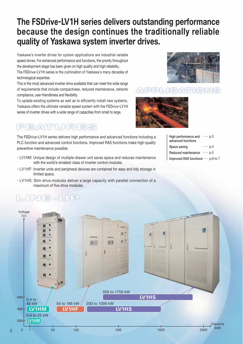
LV1HM: Unique design of multiple-drawer unit saves space and reduces maintenance with the world’s-smallest class of inverter control modules.
LV1HF: Inverter units and peripheral devices are contained for easy and tidy storage in limited space.
LV1HS: Slim drive modules deliver a large capacity with parallel connection of a maximum of five drive modules.
High performance andadvanced functions
…… p.3
Improved RAS functions
Space saving …… p.4
…… p.5
…… p.6 to 7
Reduced maintenance
Voltage( V )
Capacity(kW)
The FSDrive-LV1H series delivers outstanding performance because the design continues the traditionally reliable quality of Yaskawa system inverter drives.
LV1HS0.4 to45 kW 55 to 185 kW 200 to 1000 kW
350 to 1750 kW
0 1 50 100 2000500 1000
690
400
200
0.4 to 22 kW
LV1HM
LV1HF LV1HSLV1HM
2
PLC function
Advanced control functions
Supports a variety of control modes.
Compliant with a variety of networks
High performance and advanced functions
Delivers the high performance and advanced functionsrequired for industrial variable-speed machinery.
Unit
CP-215 I/F
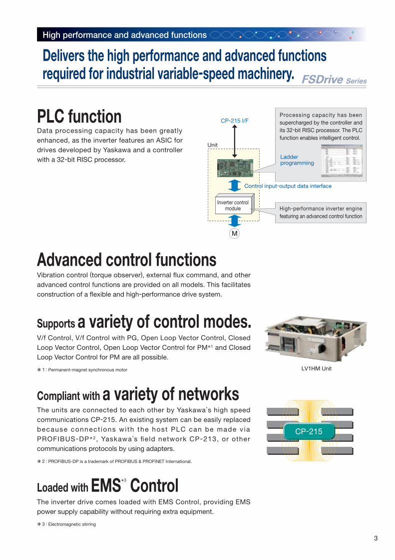
Control input-output data interface
Ladderprogramming
CP-215
Inverter controlmodule High-performance inverter engine
featuring an advanced control function
* PROFIBUS-DP is a trademark of PROFIBUS & PROFINET International.2 :
* Permanent-magnet synchronous motor1 : LV1HM Unit
FSDrive Series
Data processing capacity has been greatly enhanced, as the inverter features an ASIC for drives developed by Yaskawa and a controller with a 32-bit RISC processor.
Processing capacity has been supercharged by the controller and its 32-bit RISC processor. The PLC function enables intelligent control.
Vibration control (torque observer), external flux command, and other advanced control functions are provided on all models. This facilitates construction of a flexible and high-performance drive system.
V/f Control, V/f Control with PG, Open Loop Vector Control, Closed Loop Vector Control, Open Loop Vector Control for PM*1 and Closed Loop Vector Control for PM are all possible.
Loaded with EMS*3
Control
* Electromagnetic stirring3 :
The inverter drive comes loaded with EMS Control, providing EMS power supply capability without requiring extra equipment.
The units are connected to each other by Yaskawa’s high speed communications CP-215. An existing system can be easily replaced because connect ions wi th the host PLC can be made v ia PROFIBUS-DP*2 , Yaskawa’s field network CP-213, or other communications protocols by using adapters.
3
Super Enhanced Space Efficiency
Space saving
FSDrive Series
50% greater storage efficiencythan our previous models
A 35% smaller footprint than ourprevious models.
Flexibility in unit arrangements
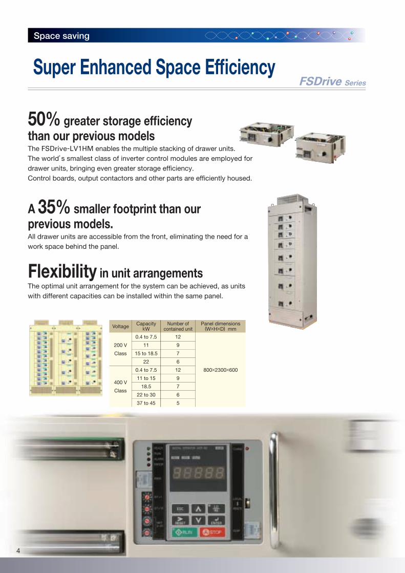
The FSDrive-LV1HM enables the multiple stacking of drawer units.The world’s smallest class of inverter control modules are employed for drawer units, bringing even greater storage efficiency.Control boards, output contactors and other parts are efficiently housed.
All drawer units are accessible from the front, eliminating the need for a work space behind the panel.
The optimal unit arrangement for the system can be achieved, as units with different capacities can be installed within the same panel.
CapacitykWVoltage Number of
contained unitPanel dimensions
(W×H×D) mm
12
9
7
6
12
9
7
6
5
800×2300×600
0.4 to 7.5
11
15 to 18.5
22
0.4 to 7.5
11 to 15
18.5
22 to 30
37 to 45
200 V
Class
400 V
Class
4
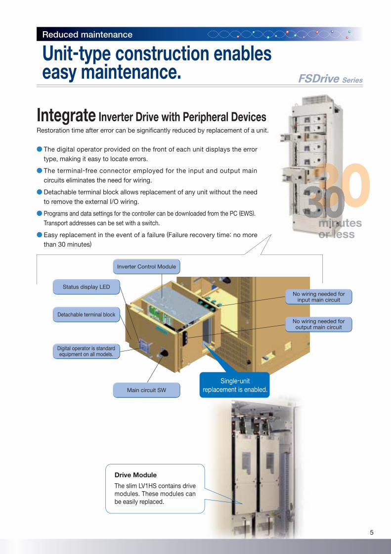
Integrate Inverter Drive with Peripheral Devices
Reduced maintenance
Inverter Control Module
Drive Module
The slim LV1HS contains drive modules. These modules can be easily replaced.
FSDrive Series
Restoration time after error can be significantly reduced by replacement of a unit.
The digital operator provided on the front of each unit displays the error type, making it easy to locate errors.
The terminal-free connector employed for the input and output main circuits eliminates the need for wiring.
Detachable terminal block allows replacement of any unit without the need to remove the external I/O wiring.
Programs and data settings for the controller can be downloaded from the PC (EWS).Transport addresses can be set with a switch.
Easy replacement in the event of a failure (Failure recovery time: no more than 30 minutes)
tesmmmmmmmmmmmmmmmiiiiiiiiiiiiiiinnnnnnnnnnnnnnnnnnnnnnnnnnnnnnnnnnnnnnnnnnnnnnnnnnnnnnnnnnnnnnnnnnnnnnuuuuuuuuuuuuuuuuuuutssooooooooooooooorrrrrrrrrrrrrrrrr lllllllllllllllllleeeeeees
Detachable terminal block
No wiring needed forinput main circuit
No wiring needed foroutput main circuit
Status display LED
Digital operator is standardequipment on all models.
Main circuit SW
Single-unitreplacement is enabled.
Unit-type construction enableseasy maintenance.
5
Management ofdata settings
Adjustment support
Troubleshooting
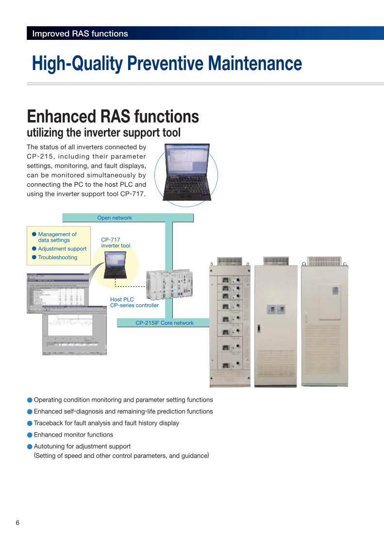
Operating condition monitoring and parameter setting functions
Enhanced self-diagnosis and remaining-life prediction functions
Traceback for fault analysis and fault history display
Enhanced monitor functions
Autotuning for adjustment support(Setting of speed and other control parameters, and guidance)
CP-215IF Core network
Open network
CP-717inverter tool
Host PLCCP-series controller
Improved RAS functions
Enhanced RAS functionsutilizing the inverter support toolThe status of all inverters connected by CP-215, including their parameter settings, monitoring, and fault displays, can be monitored simultaneously by connecting the PC to the host PLC and using the inverter support tool CP-717.
High-Quality Preventive Maintenance
6
Management of data settings
Adjustment support
Troubleshooting
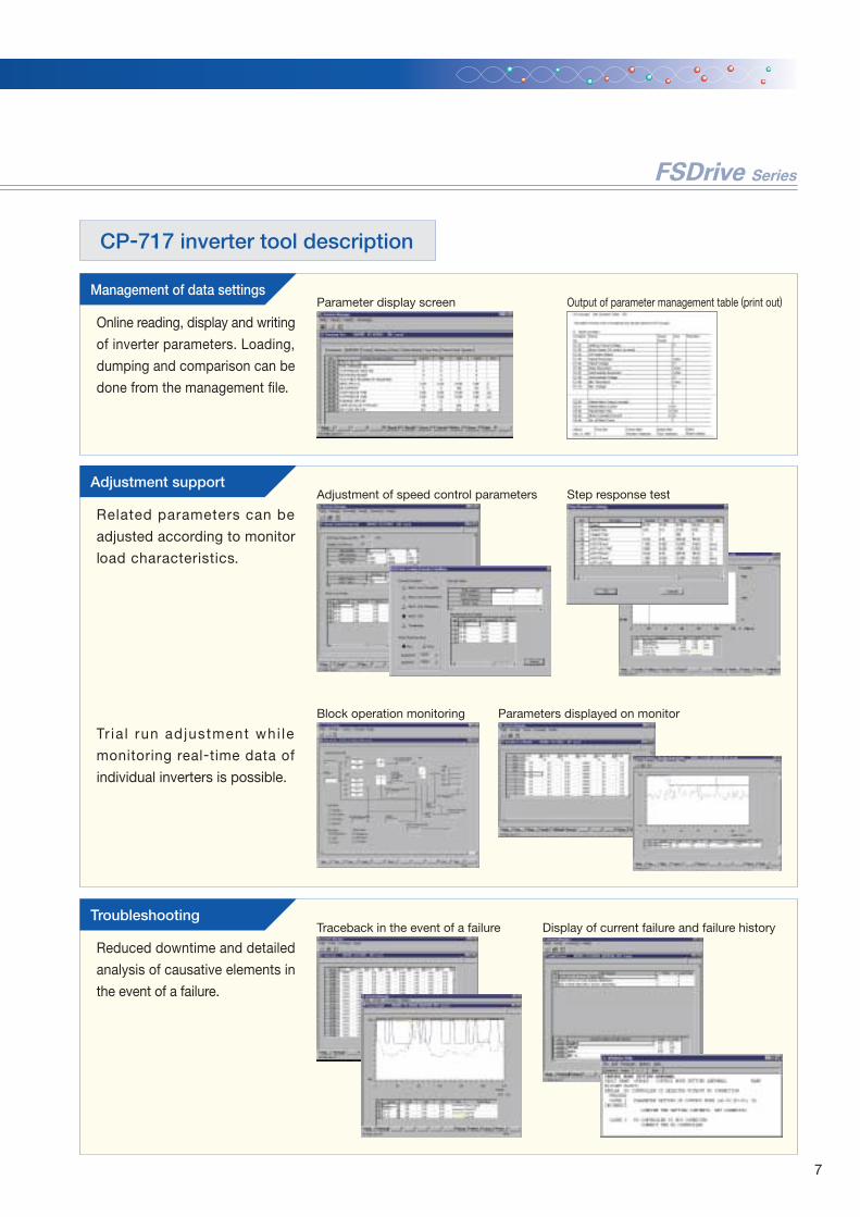
CP-717 inverter tool description
Parameter display screen Output of parameter management table (print out)
Step response testAdjustment of speed control parameters
Display of current failure and failure historyTraceback in the event of a failure
Related parameters can be
adjusted according to monitor
load characteristics.
Online reading, display and writing
of inverter parameters. Loading,
dumping and comparison can be
done from the management file.
Reduced downtime and detailed
analysis of causative elements in
the event of a failure.
Block operation monitoring Parameters displayed on monitor
Tr ia l run adjustment whi le
monitoring real-time data of
individual inverters is possible.
FSDrive Series
7
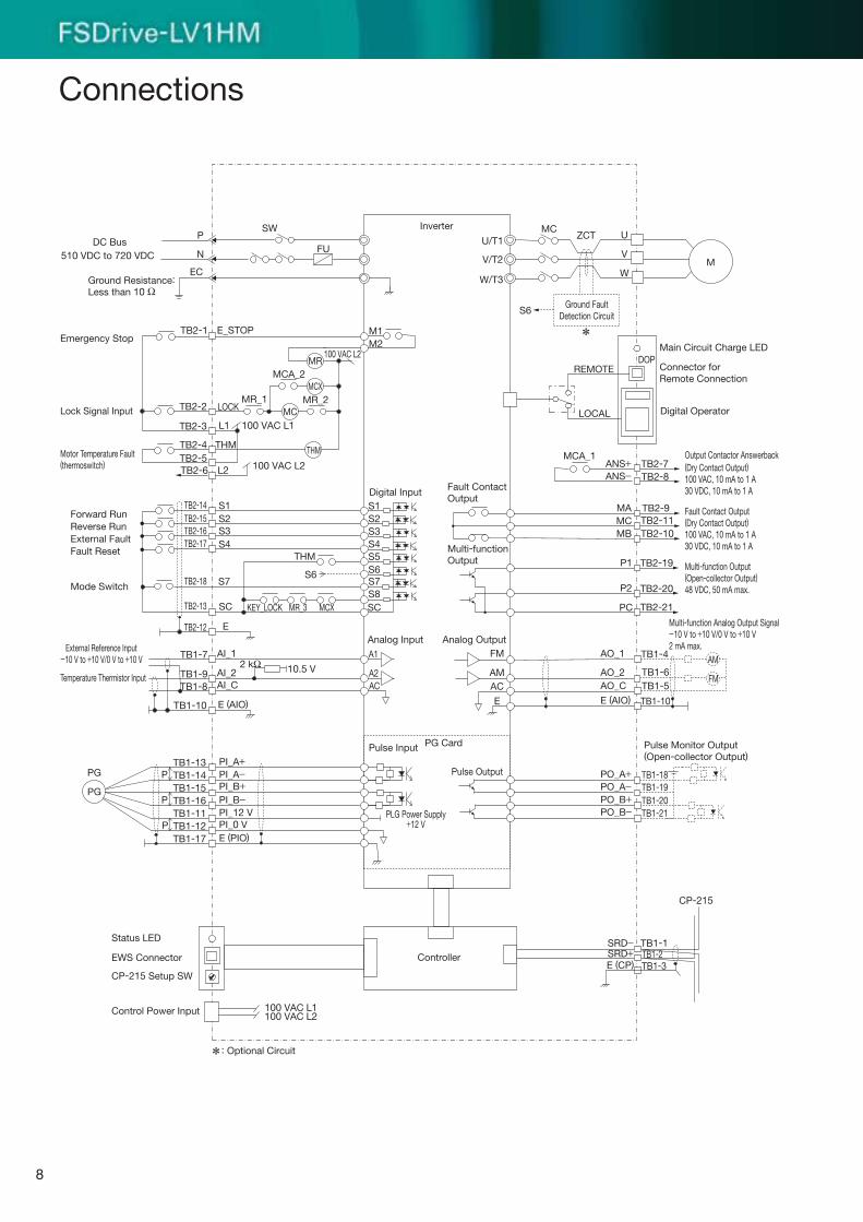
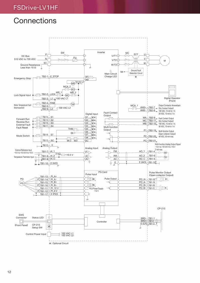
Connections
510 VDC to 720 VDC
Emergency Stop
Motor Temperature Fault(thermoswitch)
DC BusP
SW
N FUU/T1
MCZCT
MCA_1ANS+ TB2-7
TB2-8
TB2-9TB2-11TB2-10
TB2-19
TB2-20
TB2-21
TB1-4
TB1-6TB1-5
TB1-10
TB1-18
TB1-1
CP-215
TB1-2TB1-3
TB1-19TB1-20TB1-21
ANS−
MAMCMB
P1
P2
PC
AO_1FMA1
A2AC
SCS8S7S6S5S4S3S2S1S1
S2S3S4
S7S6
SC
M2
MR
MCX
THM
MC
MCA_2
MR_2MR_1
E_STOP M1
100 VAC L2
100 VAC L2
100 VAC L1
AMAC
E
AM
FMAO_2AO_C
PO_A+PO_A−PO_B+PO_B−
SRD−SRD+E (CP)
E (AIO)
U
V
WMV/T2
W/T3
Inverter
TB2-2
TB2-1
TB2-3
TB2-4TB2-5TB2-6
TB2-14TB2-15TB2-16TB2-17
TB2-18
TB2-13
TB1-7 AI_1
AI_2AI_C
10.5 V
E (AIO)
TB1-9TB1-8
TB1-10
ETB2-12
TB1-13 PI_A+PI_A−PI_B+PI_B−PI_12 VPI_0 VE (PIO)
TB1-14TB1-15TB1-16TB1-11TB1-12TB1-17
LOCK
L1
L2
THM
THM
Temperature Thermistor Input
External Reference Input-10 V to +10 V/0 V to +10 V
KEY_LOCK MR_3 MCX
2 kΩ
Lock Signal Input
Forward RunReverse RunExternal FaultFault Reset
Mode Switch
P
P
P
PG
PG
*
* Optional Circuit:
EWS Connector
Status LED
CP-215 Setup SW
Control Power Input 100 VAC L1100 VAC L2
LOCAL
REMOTEDOP
Ground Resistance:Less than 10 Ω
EC
Fault ContactOutput
Multi-functionOutput
Analog Output
Pulse Input
Digital Input
Analog Input
Pulse Output
PG Card
PLG Power Supply+12 V
Controller
Ground FaultDetection Circuit
Output Contactor Answerback(Dry Contact Output)100 VAC, 10 mA to 1 A30 VDC, 10 mA to 1 A
Fault Contact Output(Dry Contact Output)100 VAC, 10 mA to 1 A30 VDC, 10 mA to 1 A
Multi-function Output(Open-collector Output)48 VDC, 50 mA max.
Multi-function Analog Output Signal-10 V to +10 V/0 V to +10 V2 mA max.
Pulse Monitor Output(Open-collector Output)
Digital Operator
Connector forRemote Connection
Main Circuit Charge LED
S6
8
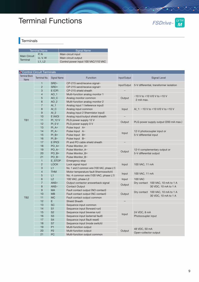
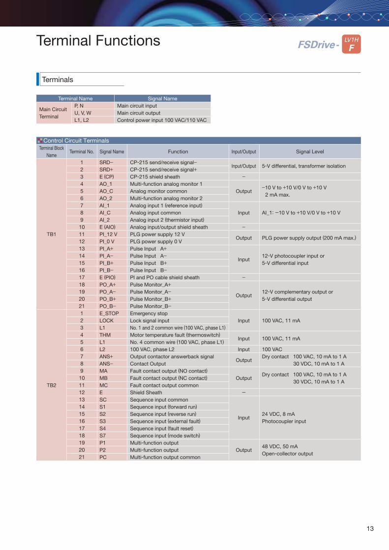
Terminals
Terminal Functions
Terminal NameP, N U, V, WL1, L2
Signal NameMain circuit inputMain circuit output Control power input 100 VAC/110 VAC
Control Circuit Terminals
Main CircuitTerminal
LV1HLV1H
MFSDrive-
Terminal Block Name
TB1
TB2
Terminal No.
123456789101112131415161718192021123456789101112131415161718192021
Signal Name
SRD−SRD+E (CP)
AO_1AO_CAO_2AI_1AI_CAI_2E (AIO)
PI_12 VPI_0 VPI_A+PI_A−PI_B+PI_B−E (PIO)
PO_A+PO_A−PO_B+PO_B−E_STOPLOCKL1THML1L2ANS+ANS−MAMBMCESCS1S2S3S4S7P1P2PC
Input/Output
Input/Output
−
Output
Input
−
Output
Input
−
Output
Input
Input
Input
Output
Output
-
Input
Output
Function
CP-215 send/receive signal−CP-215 send/receive signal+CP-215 shield sheathMulti-function analog monitor 1Analog monitor commonMulti-function analog monitor 2Analog input 1 (reference input)
Analog input commonAnalog input 2 (thermistor input)
Analog input/output shield sheathPLG power supply 12 VPLG power supply 0 VPulse Input A+Pulse Input A−Pulse Input B+Pulse Input B−PI and PO cable shield sheathPulse Monitor_A+Pulse Monitor_A−Pulse Monitor_B+Pulse Monitor_B−Emergency stopLock signal inputNo. 1 and 2 common wire (100 VAC, phase L1)
Motor temperature fault (thermoswitch)
No. 4 common wire (100 VAC, phase L1)
100 VAC, phase L2Output contactor answerback signalContact OutputFault contact output (NO contact)
Fault contact output (NC contact)
Fault contact output commonShield SheathSequence input commonSequence input (forward run)
Sequence input (reverse run)
Sequence input (external fault)
Sequence input (fault reset)
Sequence input (mode switch)
Multi-function outputMulti-function outputMulti-function output common
Signal Level
5-V differential, transformer isolation
−10 V to +10 V/0 V to +10 V2 mA max.
AI_1: -10 V to +10 V/0 V to +10 V
PLG power supply output (200 mA max.)
12-V photocoupler input or5-V differential input
12-V complementary output or5-V differential output
100 VAC, 11 mA
100 VAC, 11 mA
100 VACDry contact 100 VAC, 10 mA to 1 A
30 VDC, 10 mA to 1 A
Dry contact 100 VAC, 10 mA to 1 A30 VDC, 10 mA to 1 A
24 VDC, 8 mAPhotocoupler input
48 VDC, 50 mAOpen-collector output
9
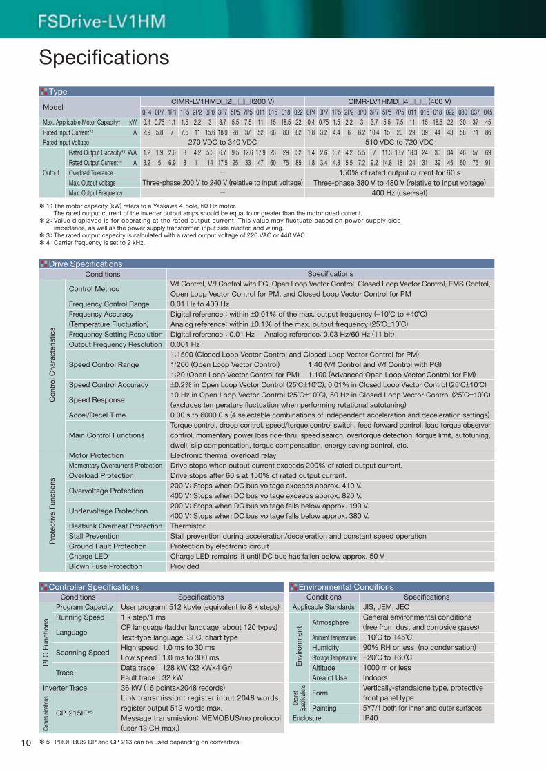
Specifications
****
The motor capacity (kW) refers to a Yaskawa 4-pole, 60 Hz motor. The rated output current of the inverter output amps should be equal to or greater than the motor rated current.Value displayed is for operating at the rated output current. This value may fluctuate based on power supply side impedance, as well as the power supply transformer, input side reactor, and wiring.The rated output capacity is calculated with a rated output voltage of 220 VAC or 440 VAC.Carrier frequency is set to 2 kHz.
1
2
34
:
:
::
Conditions
Control Method
Frequency Control RangeFrequency Accuracy(Temperature Fluctuation)
Frequency Setting ResolutionOutput Frequency Resolution
Speed Control Range
Speed Control Accuracy
Speed Response
Accel/Decel Time
Main Control Functions
Motor ProtectionMomentary Overcurrent ProtectionOverload Protection
Overvoltage Protection
Undervoltage Protection
Heatsink Overheat ProtectionStall PreventionGround Fault ProtectionCharge LEDBlown Fuse Protection
Conditions
Inverter Trace
Program CapacityRunning Speed
Language
Scanning Speed
Trace
CP-215IF*5
SpecificationsV/f Control, V/f Control with PG, Open Loop Vector Control, Closed Loop Vector Control, EMS Control, Open Loop Vector Control for PM, and Closed Loop Vector Control for PM0.01 Hz to 400 HzDigital reference : within ±0.01% of the max. output frequency (−10˚C to +40˚C)
Analog reference: within ±0.1% of the max. output frequency (25˚C±10˚C)
Digital reference : 0.01 Hz Analog reference: 0.03 Hz/60 Hz (11 bit)
0.001 Hz1:1500 (Closed Loop Vector Control and Closed Loop Vector Control for PM)
1:200 (Open Loop Vector Control) 1:40 (V/f Control and V/f Control with PG)
1:20 (Open Loop Vector Control for PM) 1:100 (Advanced Open Loop Vector Control for PM)
±0.2% in Open Loop Vector Control (25˚C±10˚C), 0.01% in Closed Loop Vector Control (25˚C±10˚C)
10 Hz in Open Loop Vector Control (25˚C±10˚C), 50 Hz in Closed Loop Vector Control (25˚C±10˚C) (excludes temperature fluctuation when performing rotational autotuning)
0.00 s to 6000.0 s (4 selectable combinations of independent acceleration and deceleration settings)
Torque control, droop control, speed/torque control switch, feed forward control, load torque observer control, momentary power loss ride-thru, speed search, overtorque detection, torque limit, autotuning, dwell, slip compensation, torque compensation, energy saving control, etc.Electronic thermal overload relayDrive stops when output current exceeds 200% of rated output current.Drive stops after 60 s at 150% of rated output current.200 V: Stops when DC bus voltage exceeds approx. 410 V.400 V: Stops when DC bus voltage exceeds approx. 820 V.200 V: Stops when DC bus voltage falls below approx. 190 V.400 V: Stops when DC bus voltage falls below approx. 380 V.ThermistorStall prevention during acceleration/deceleration and constant speed operationProtection by electronic circuitCharge LED remains lit until DC bus has fallen below approx. 50 VProvided
SpecificationsUser program: 512 kbyte (equivalent to 8 k steps)
1 k step/1 msCP language (ladder language, about 120 types)
Text-type language, SFC, chart typeHigh speed: 1.0 ms to 30 msLow speed : 1.0 ms to 300 msData trace : 128 kW (32 kW×4 Gr)
Fault trace : 32 kW36 kW (16 points×2048 records)
Link transmission: register input 2048 words, register output 512 words max.Message transmission: MEMOBUS/no protocol (user 13 CH max.)
ConditionsApplicable Standards
Enclosure
Atmosphere
Ambient TemperatureHumidityStorage TemperatureAltitudeArea of Use
Form
Painting
SpecificationsJIS, JEM, JECGeneral environmental conditions(free from dust and corrosive gases)−10˚C to +45˚C90% RH or less (no condensation)−20˚C to +60˚C1000 m or lessIndoorsVertically-standalone type, protective front panel type5Y7/1 both for inner and outer surfacesIP40
Drive Specifications
Controller Specifications Environmental Conditions
* PROFIBUS-DP and CP-213 can be used depending on converters.5 :
Con
trol
Cha
ract
eris
tics
Pro
tect
ive
Func
tions
PLC
Fun
ctio
nsCo
mmun
icatio
ns
Env
ironm
ent
Cabin
etSp
ecific
ation
s
Model
Max. Applicable Motor Capacity*1
Rated Input Current*2
Rated Input Voltage
Output
0P40.41.8
1.41.8
0P40.42.9
1.23.2
1P11.17
2.66.9
0P70.755.8
1.95
1P51.57.5
38
2P22.211
4.211
3P03
15.6
5.314
3P73.718.9
6.717.5
7P57.537
12.633
0111152
17.947
0151568
2360
01818.580
2975
0222282
3285
5P55.528
9.525
0P70.753.2
2.63.4
1P51.54.4
3.74.8
2P22.26
4.25.5
3P03
8.2
5.57.2
3P73.710.4
79.2
5P55.515
11.314.8
7P57.520
13.718
0111129
18.324
0151539
2431
01818.544
3039
0222243
3445
0303058
4660
0373771
5775
0454586
6991
kWA
kVAA
Rated Output Capacity*3
Rated Output Current*4
Overload ToleranceMax. Output VoltageMax. Output Frequency
150% of rated output current for 60 sThree-phase 380 V to 480 V (relative to input voltage)
400 Hz (user-set)
510 VDC to 720 VDC270 VDC to 340 VDC
Type
-Three-phase 200 V to 240 V (relative to input voltage)
-
CIMR-LV1HMD 2 (200 V) CIMR-LV1HMD 4 (400 V)
10
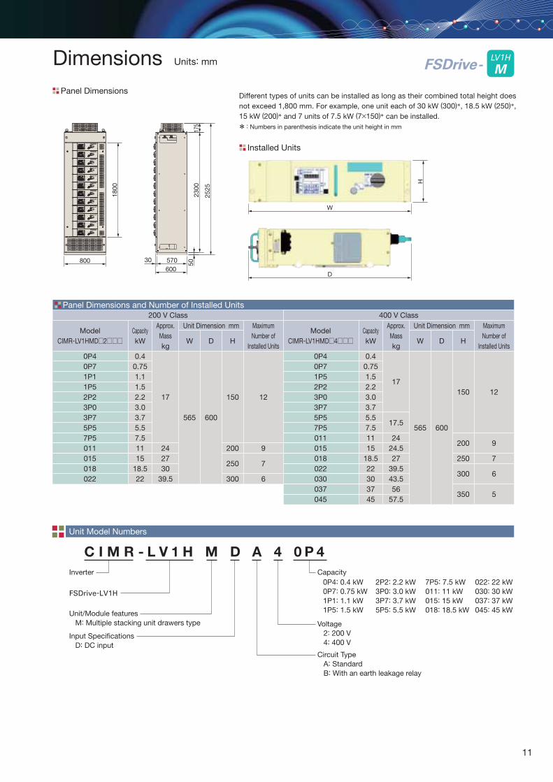
Different types of units can be installed as long as their combined total height does not exceed 1,800 mm. For example, one unit each of 30 kW (300)*, 18.5 kW (250)*, 15 kW (200)* and 7 units of 7.5 kW (7×150)* can be installed.
Panel Dimensions and Number of Installed Units
Panel Dimensions
Installed Units
Dimensions Units: mm
* Numbers in parenthesis indicate the unit height in mm :
800 5023
00
1800
H
175
2525
570
W
D600
30
LV1HLV1H
MFSDrive-
ModelCIMR-LV1HMD 4
0P40P71P52P23P03P75P57P5011015018022030037045
CapacitykW
0.40.751.52.23.03.75.57.51115
18.522303745
Approx. Masskg
17
17.5
2424.527
39.543.556
57.5
W
565
Unit Dimension mm
D
600
H
150
200
250
300
350
Maximum Number of
Installed Units
12
9
7
6
5
ModelCIMR-LV1HMD 2
0P40P71P11P52P23P03P75P57P5011015018022
CapacitykW
0.40.751.11.52.23.0 3.75.57.51115
18.522
Approx. Masskg
17
242730
39.5
W
565
Unit Dimension mm
D
600
H
150
200
250
300
Maximum Number of
Installed Units
12
9
7
6
Unit Model Numbers
C I M R - L V 1 H M D A 4 0 P 4
Inverter
FSDrive-LV1H
Voltage 2: 200 V 4: 400 V
Unit/Module features M: Multiple stacking unit drawers type
Circuit Type A: Standard B: With an earth leakage relay
Input Specifications D: DC input
Capacity0P4: 0.4 kW0P7: 0.75 kW1P1: 1.1 kW1P5: 1.5 kW
2P2: 2.2 kW3P0: 3.0 kW3P7: 3.7 kW5P5: 5.5 kW
022: 22 kW030: 30 kW037: 37 kW045: 45 kW
7P5: 7.5 kW011: 11 kW015: 15 kW018: 18.5 kW
200 V Class 400 V Class
11
PSW
N FUU/T1
MCZCT
MCA_1ANS+ TB2-7
TB2-8
TB2-9TB2-11TB2-10
TB2-19
TB2-20
TB2-21
TB1-4
TB1-6TB1-5
TB1-10
TB1-18
TB1-1
CP-215
TB1-2TB1-3
TB1-19TB1-20TB1-21
ANS−
MAMCMB
P1
P2
PC
AO_1FMA1
A2AC
SCS8S7S6S5S4S3S2S1S1
S2S3S4
S7S6
SC
M2
MR
MCX
THM
MC
MCA_2
MR_2MR_1
E_STOP M1
AMAC
E
AM
FMAO_2AO_C
PO_A+PO_A−PO_B+PO_B−
SRD−SRD+
Pulse Input
U
V
WMV/T2
W/T3
TB2-2
TB2-1
TB2-3
TB2-4TB2-5TB2-6
TB2-14TB2-15TB2-16TB2-17
TB2-18
TB2-13
TB1-7 AI_1
AI_2AI_C
TB1-9TB1-8
TB1-10
ETB2-12
TB1-13 PI_A+PI_A−PI_B+PI_B−
TB1-14TB1-15TB1-16TB1-11TB1-12TB1-17
LOCK
L1
L2
THM
THM
MR_3 MCX
P
P
P
PG
PG
Status LEDEWS
Connector
(Front Panel) CP-215Setup SW
EC
Main CircuitCharge LED
Digital Operator(Front)
*
Ground FaultDetection CircuitS6
Emergency Stop
Motor Temperature Fault(thermoswitch)
100 VAC L2
100 VAC L2
100 VAC L1
Inverter
10.5 VTemperature Thermistor Input
External Reference Input-10 V to +10 V/0 V to +10 V 2 kΩ
Lock Signal Input
Forward RunReverse RunExternal FaultFault Reset
* Optional Circuit:
Control Power Input 100 VAC L1100 VAC L2
Ground Resistance:Less than 10 Ω
Fault ContactOutput
Analog Output
Digital Input
Analog Input
Pulse Output
PG Card
PLG Power Supply+12 V
Controller
Output Contactor Answerback(Dry Contact Output)100 VAC, 10 mA to 1 A30 VDC, 10 mA to 1 A
Fault Contact Output(Dry Contact Output)100 VAC, 10 mA to 1 A30 VDC, 10 mA to 1 A
Multi-function Output(Open-collector Output)48 VDC, 50 mA max.
Multi-function Analog Output Signal-10 V to +10 V/0 V to +10 V2 mA max.
Pulse Monitor Output(Open-collector Output)
Multi-functionOutput
PI_12 VPI_0 V
Connections
510 VDC to 720 VDCDC Bus
E (CP)
E (AIO)E (AIO)
E (PIO)
Mode Switch
12
P, N U, V, WL1, L2
Control Circuit Terminals
LV1H
FFSDrive-
Terminals
Terminal Functions
Terminal Name Signal NameMain circuit inputMain circuit output Control power input 100 VAC/110 VAC
Main CircuitTerminal
Terminal Block Name
TB1
TB2
Terminal No.
123456789101112131415161718192021123456789101112131415161718192021
Signal Name
SRD−SRD+E (CP)
AO_1AO_CAO_2AI_1AI_CAI_2E (AIO)
PI_12 VPI_0 VPI_A+PI_A−PI_B+PI_B−E (PIO)
PO_A+PO_A−PO_B+PO_B−E_STOPLOCKL1THML1L2ANS+ANS−MAMBMCESCS1S2S3S4S7P1P2PC
Input/Output
Input/Output
−
Output
Input
−
Output
Input
−
Output
Input
Input
Input
Output
Output
-
Input
Output
Function
CP-215 send/receive signal−CP-215 send/receive signal+CP-215 shield sheathMulti-function analog monitor 1Analog monitor commonMulti-function analog monitor 2Analog input 1 (reference input)
Analog input commonAnalog input 2 (thermistor input)
Analog input/output shield sheathPLG power supply 12 VPLG power supply 0 VPulse Input A+Pulse Input A−Pulse Input B+Pulse Input B−PI and PO cable shield sheathPulse Monitor_A+Pulse Monitor_A−Pulse Monitor_B+Pulse Monitor_B−Emergency stopLock signal inputNo. 1 and 2 common wire (100 VAC, phase L1)
Motor temperature fault (thermoswitch)
No. 4 common wire (100 VAC, phase L1)
100 VAC, phase L2Output contactor answerback signalContact OutputFault contact output (NO contact)
Fault contact output (NC contact)
Fault contact output commonShield SheathSequence input commonSequence input (forward run)
Sequence input (reverse run)
Sequence input (external fault)
Sequence input (fault reset)
Sequence input (mode switch)
Multi-function outputMulti-function outputMulti-function output common
Signal Level
5-V differential, transformer isolation
−10 V to +10 V/0 V to +10 V2 mA max.
AI_1: -10 V to +10 V/0 V to +10 V
PLG power supply output (200 mA max.)
12-V photocoupler input or5-V differential input
12-V complementary output or5-V differential output
100 VAC, 11 mA
100 VAC, 11 mA
100 VACDry contact 100 VAC, 10 mA to 1 A
30 VDC, 10 mA to 1 A
Dry contact 100 VAC, 10 mA to 1 A30 VDC, 10 mA to 1 A
24 VDC, 8 mAPhotocoupler input
48 VDC, 50 mAOpen-collector output
13
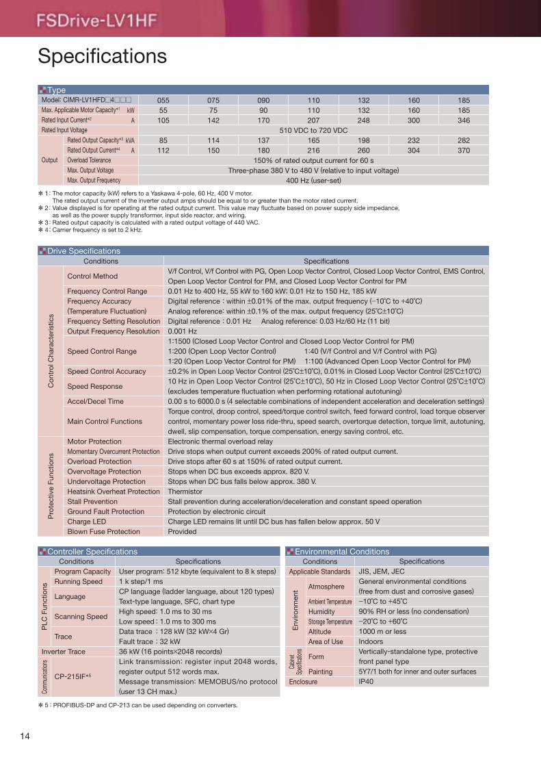
05555
105
85112
07575
142
114150
09090170
137180
110110207
165216
132132248
198260
160160300
232304
185185346
282370
Specifications
Model: CIMR-LV1HFD 4Max. Applicable Motor Capacity*1
Rated Input Current*2
Rated Input Voltage
Output
kWA
kVAA
Rated Output Capacity*3
Rated Output Current*4
Overload ToleranceMax. Output VoltageMax. Output Frequency
Conditions
Control Method
Frequency Control RangeFrequency Accuracy(Temperature Fluctuation)
Frequency Setting ResolutionOutput Frequency Resolution
Speed Control Range
Speed Control Accuracy
Speed Response
Accel/Decel Time
Main Control Functions
Motor ProtectionMomentary Overcurrent ProtectionOverload ProtectionOvervoltage ProtectionUndervoltage ProtectionHeatsink Overheat ProtectionStall PreventionGround Fault ProtectionCharge LEDBlown Fuse Protection
510 VDC to 720 VDC
150% of rated output current for 60 sThree-phase 380 V to 480 V (relative to input voltage)
400 Hz (user-set)
Conditions
Inverter Trace
Program CapacityRunning Speed
Language
Scanning Speed
Trace
CP-215IF*5
SpecificationsV/f Control, V/f Control with PG, Open Loop Vector Control, Closed Loop Vector Control, EMS Control, Open Loop Vector Control for PM, and Closed Loop Vector Control for PM0.01 Hz to 400 Hz, 55 kW to 160 kW; 0.01 Hz to 150 Hz, 185 kWDigital reference : within ±0.01% of the max. output frequency (−10˚C to +40˚C)
Analog reference: within ±0.1% of the max. output frequency (25˚C±10˚C)
Digital reference : 0.01 Hz Analog reference: 0.03 Hz/60 Hz (11 bit)
0.001 Hz1:1500 (Closed Loop Vector Control and Closed Loop Vector Control for PM)
1:200 (Open Loop Vector Control) 1:40 (V/f Control and V/f Control with PG)
1:20 (Open Loop Vector Control for PM) 1:100 (Advanced Open Loop Vector Control for PM)
±0.2% in Open Loop Vector Control (25˚C±10˚C), 0.01% in Closed Loop Vector Control (25˚C±10˚C)
10 Hz in Open Loop Vector Control (25˚C±10˚C), 50 Hz in Closed Loop Vector Control (25˚C±10˚C) (excludes temperature fluctuation when performing rotational autotuning)
0.00 s to 6000.0 s (4 selectable combinations of independent acceleration and deceleration settings)
Torque control, droop control, speed/torque control switch, feed forward control, load torque observer control, momentary power loss ride-thru, speed search, overtorque detection, torque limit, autotuning, dwell, slip compensation, torque compensation, energy saving control, etc.Electronic thermal overload relayDrive stops when output current exceeds 200% of rated output current.Drive stops after 60 s at 150% of rated output current.Stops when DC bus exceeds approx. 820 V.Stops when DC bus falls below approx. 380 V.ThermistorStall prevention during acceleration/deceleration and constant speed operationProtection by electronic circuitCharge LED remains lit until DC bus has fallen below approx. 50 VProvided
SpecificationsUser program: 512 kbyte (equivalent to 8 k steps)
1 k step/1 msCP language (ladder language, about 120 types)
Text-type language, SFC, chart typeHigh speed: 1.0 ms to 30 msLow speed : 1.0 ms to 300 msData trace : 128 kW (32 kW×4 Gr)
Fault trace : 32 kW36 kW (16 points×2048 records)
Link transmission: register input 2048 words, register output 512 words max.Message transmission: MEMOBUS/no protocol (user 13 CH max.)
ConditionsApplicable Standards
Enclosure
Atmosphere
Ambient TemperatureHumidityStorage TemperatureAltitudeArea of Use
Form
Painting
SpecificationsJIS, JEM, JECGeneral environmental conditions(free from dust and corrosive gases)−10˚C to +45˚C90% RH or less (no condensation)−20˚C to +60˚C1000 m or lessIndoorsVertically-standalone type, protective front panel type5Y7/1 both for inner and outer surfacesIP40
Type
Drive Specifications
Controller Specifications Environmental Conditions
* PROFIBUS-DP and CP-213 can be used depending on converters.5 :
****
The motor capacity (kW) refers to a Yaskawa 4-pole, 60 Hz, 400 V motor. The rated output current of the inverter output amps should be equal to or greater than the motor rated current.Value displayed is for operating at the rated output current. This value may fluctuate based on power supply side impedance, as well as the power supply transformer, input side reactor, and wiring.Rated output capacity is calculated with a rated output voltage of 440 VAC.Carrier frequency is set to 2 kHz.
1
2
34
:
:
::
Con
trol
Cha
ract
eris
tics
Pro
tect
ive
Func
tions
PLC
Fun
ctio
nsCo
mmun
icatio
ns
Env
ironm
ent
Cabin
etSp
ecific
ation
s
14
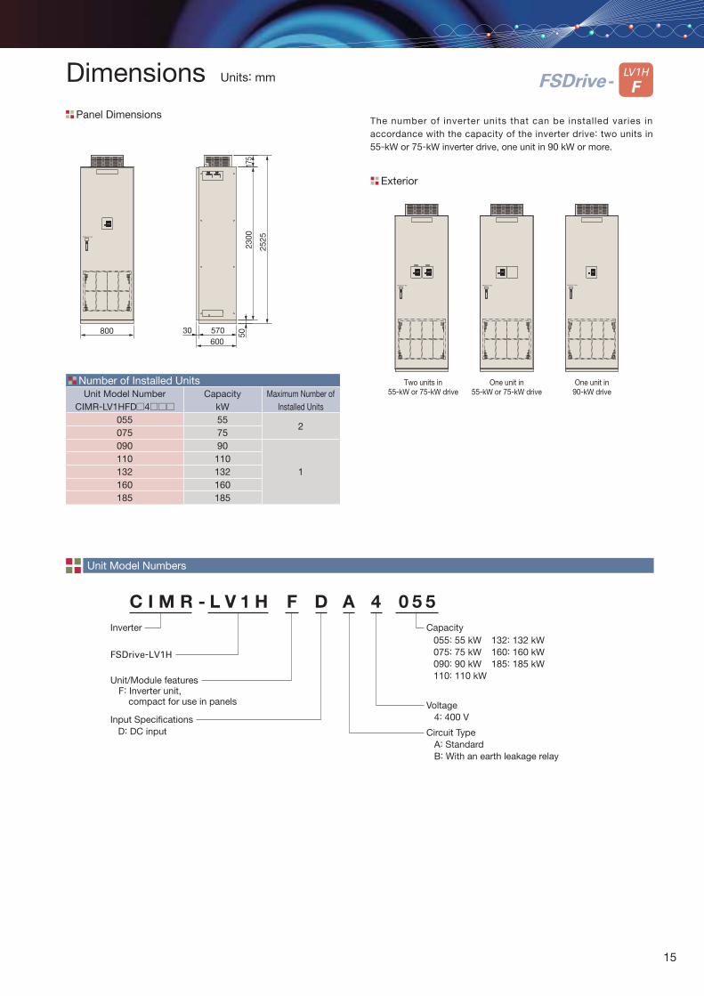
C I M R - L V 1 H F D A 4 0 5 5
Inverter055: 55 kW075: 75 kW090: 90 kW110: 110 kW
FSDrive-LV1H
Voltage 4: 400 V
Unit/Module features F: Inverter unit, compact for use in panels
Circuit Type A: Standard B: With an earth leakage relay
Capacity
Unit Model Numbers
132: 132 kW160: 160 kW185: 185 kW
The number of inverter units that can be installed varies in accordance with the capacity of the inverter drive: two units in 55-kW or 75-kW inverter drive, one unit in 90 kW or more.
Number of Installed Units
Exterior
Unit Model NumberCIMR-LV1HFD 4
055075090110132160185
CapacitykW557590
110132160185
Maximum Number of Installed Units
2
1
5023
0017
5
2525
570600
30800
Two units in55-kW or 75-kW drive
One unit in55-kW or 75-kW drive
One unit in90-kW drive
LV1H
FLV1H
FFSDrive-
Panel Dimensions
Dimensions Units: mm
Input Specifications D: DC input
15
External Reference Input
M
Analog Output
Pulse Input
Fault ContactOutput
Digital Input
AO_1
AO_2AO_C
AI_3
THMTHM
PG
PG
Forward RunReverse RunExternal FaultFault Reset
P1
Controller
P2
PC
Jog Speed Reference
S1S2S3S4
S7
SC
P
P
P
Pulse OutputPO_A+
MB
MAMC
P
NDC Bus U
VW
Digital Operator
SRD−SRD+
SH
CP-215
FM
AMAC
Fault Contact Output(Dry Contact Output)250 VAC, 1 A max.30 VDC, 1 A max.
PG Card
PO_A−PO_B+PO_B−
0 V to +10 V
A3
THM_M1THM_M2
PI_A+PI_A−PI_B+PI_B−PI_12 VPI_0 VE
1TB-41TB-51TB-61TB-71TB-11TB-21TB-8
1TB-301TB-311TB-321TB-33
1TB-45
1TB-481TB-49
1TB-19
1TB-20
1TB-50
1TB-42
1TB-271TB-28
1TB-17
1TB-15
1TB-121TB-111TB-101TB-9
1TB-251TB-231TB-52
JC01-2JC01-1
Multi-functionOutput
EWS Connector
Status LED
CP-215 Setup SW
Main Circuit Charge LED
S5S6
S8
S1S2S3S4
S7
SC
S5S6
S8
1TB-131TB-14
1TB-16
AC AO_C
Analog Input
A1
A2
AI_11TB-36AI_C1TB-37
AI_21TB-39AI_C1TB-40
AI_C AC
AC
AC
1TB-46
+V1TB-34−V1TB-44
+10.5 V−10.5 V
1TB-43
V+V−
JC01-S
JC02-4JC02-3JC02-E
SRD+SRD−
M11TB-55M2
M1M21TB-56
Main/Aux. SwitchMulti-Speed Step Reference
External Baseblock
SRD−SRD+
SH
4 mA to 20 mA
0 V to +10 V
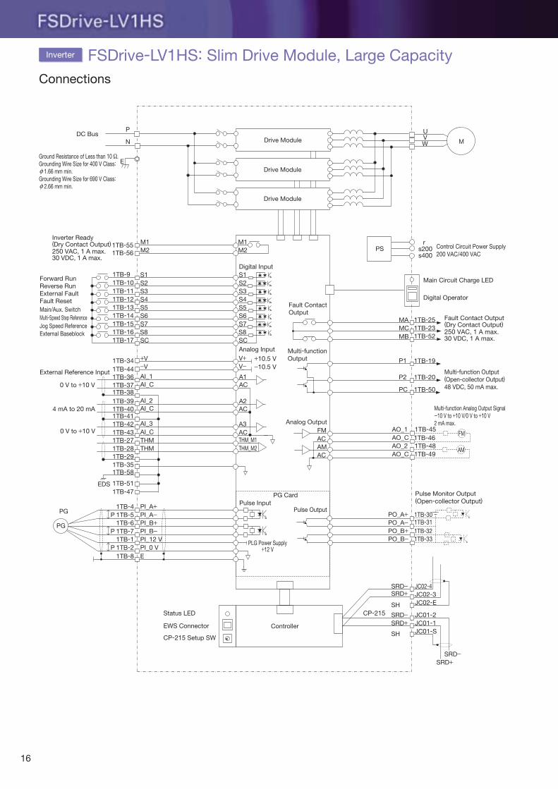
Inverter Ready(Dry Contact Output)250 VAC, 1 A max.30 VDC, 1 A max.
rs200s400
Control Circuit Power Supply200 VAC/400 VAC
主回路
主回路
PS
Drive Module
Drive Module
Drive Module
1TB-38
1TB-41
1TB-29
1TB-58
EDS 1TB-511TB-47
1TB-35
Pulse Monitor Output(Open-collector Output)
FM
AM
PLG Power Supply+12 V
Multi-function Output(Open-collector Output)48 VDC, 50 mA max.
Multi-function Analog Output Signal-10 V to +10 V/0 V to +10 V2 mA max.
FSDrive-LV1HS: Slim Drive Module, Large CapacityInverter
Connections
EGround Resistance of Less than 10 Ω.Grounding Wire Size for 400 V Class: 1.66 mm min.Grounding Wire Size for 690 V Class: 2.66 mm min.
ϕ
ϕ
16
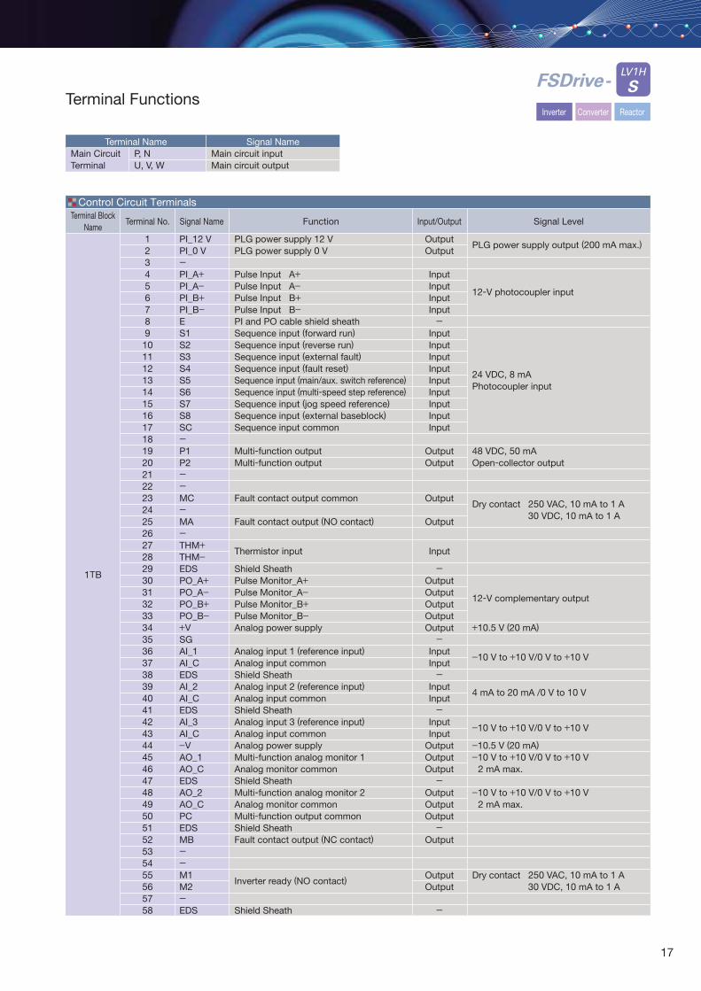
Terminal NameP, N U, V, W
Signal NameMain circuit inputMain circuit output
Control Circuit Terminals
Main CircuitTerminal
Terminal Functions
LV1H
SFSDrive-
Inverter Converter Reactor
Terminal Block Name
1TB
Terminal No.
12345678910111213141516171819202122232425262728293031323334353637383940414243444546474849505152535455565758
Signal Name
PI_12 VPI_0 V-PI_A+PI_A−PI_B+PI_B−ES1S2S3S4S5S6S7S8SC-P1P2--MC-MA-THM+THM−EDSPO_A+PO_A−PO_B+PO_B−+VSGAI_1AI_CEDSAI_2AI_CEDSAI_3AI_C−VAO_1AO_CEDSAO_2AO_CPCEDSMB--M1M2-EDS
Input/Output
OutputOutput
InputInputInputInput-
InputInputInputInputInputInputInputInputInput
OutputOutput
Output
Output
Input
-OutputOutputOutputOutputOutput-
InputInput-
InputInput-
InputInput
OutputOutputOutput-
OutputOutputOutput-
Output
OutputOutput
-
Function
PLG power supply 12 VPLG power supply 0 V
Pulse Input A+Pulse Input A−Pulse Input B+Pulse Input B−PI and PO cable shield sheathSequence input (forward run)Sequence input (reverse run)Sequence input (external fault)Sequence input (fault reset)Sequence input (main/aux. switch reference)Sequence input (multi-speed step reference)Sequence input (jog speed reference)Sequence input (external baseblock)Sequence input common
Multi-function outputMulti-function output
Fault contact output common
Fault contact output (NO contact)
Thermistor input
Shield SheathPulse Monitor_A+Pulse Monitor_A−Pulse Monitor_B+Pulse Monitor_B−Analog power supply
Analog input 1 (reference input)Analog input commonShield SheathAnalog input 2 (reference input)Analog input commonShield SheathAnalog input 3 (reference input) Analog input commonAnalog power supplyMulti-function analog monitor 1Analog monitor commonShield SheathMulti-function analog monitor 2Analog monitor commonMulti-function output commonShield SheathFault contact output (NC contact)
Inverter ready (NO contact)
Shield Sheath
Signal Level
PLG power supply output (200 mA max.)
12-V photocoupler input
24 VDC, 8 mAPhotocoupler input
48 VDC, 50 mAOpen-collector output
Dry contact 250 VAC, 10 mA to 1 A30 VDC, 10 mA to 1 A
12-V complementary output
+10.5 V (20 mA)
−10 V to +10 V/0 V to +10 V
4 mA to 20 mA /0 V to 10 V
−10 V to +10 V/0 V to +10 V
−10.5 V (20 mA)−10 V to +10 V/0 V to +10 V
2 mA max.
−10 V to +10 V/0 V to +10 V2 mA max.
Dry contact 250 VAC, 10 mA to 1 A30 VDC, 10 mA to 1 A
17
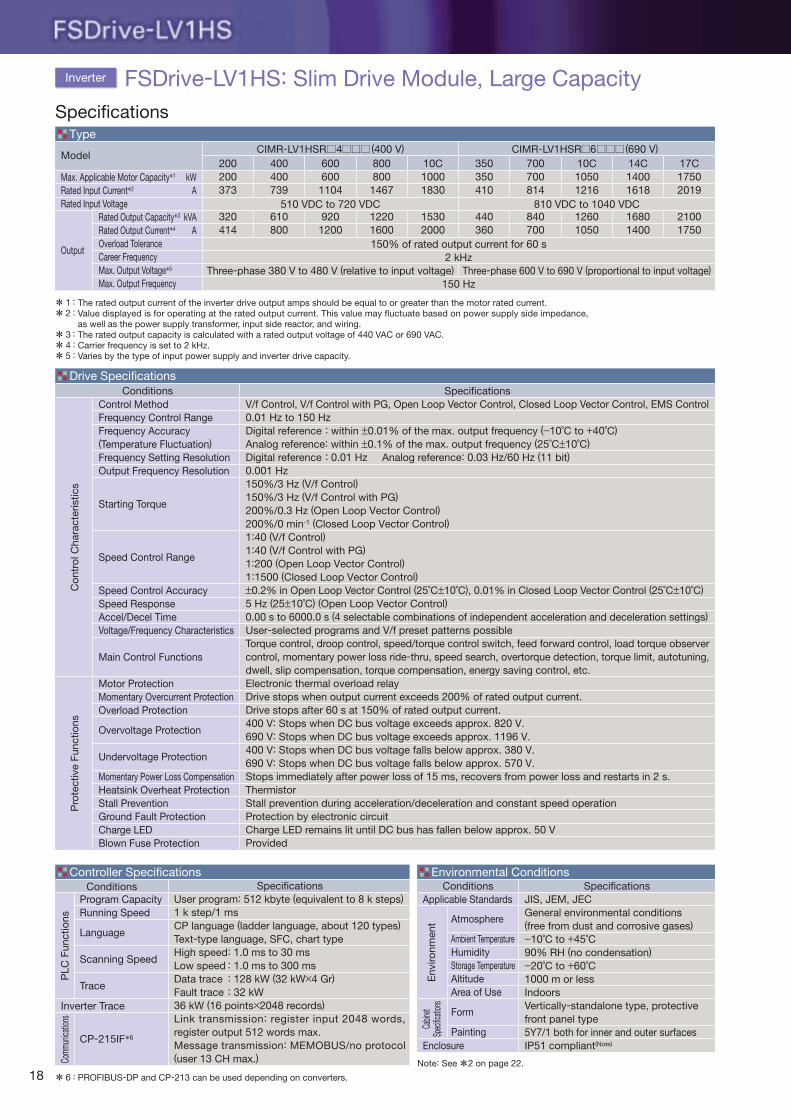
Max. Applicable Motor Capacity*1
Rated Input Current*2
Rated Input Voltage
Output
Model200200373
320414
CIMR-LV1HSR 4 (400 V) CIMR-LV1HSR 6 (690 V)
Three-phase 380 V to 480 V (relative to input voltage) Three-phase 600 V to 690 V (proportional to input voltage)
400400739
610800
600600
1104
9201200
8008001467
12201600
10C10001830
15302000
350350410
440360
700700814
840700
10C10501216
12601050
14C14001618
16801400
17C17502019
21001750
kWA
kVAA
Rated Output Capacity*3
Rated Output Current*4
Overload ToleranceCareer FrequencyMax. Output Voltage*5
Max. Output Frequency
ConditionsControl MethodFrequency Control RangeFrequency Accuracy(Temperature Fluctuation)Frequency Setting ResolutionOutput Frequency Resolution
Starting Torque
Speed Control Range
Speed Control AccuracySpeed ResponseAccel/Decel TimeVoltage/Frequency Characteristics
Main Control Functions
Motor ProtectionMomentary Overcurrent ProtectionOverload Protection
Overvoltage Protection
Undervoltage Protection Momentary Power Loss CompensationHeatsink Overheat ProtectionStall PreventionGround Fault ProtectionCharge LEDBlown Fuse Protection
150% of rated output current for 60 s2 kHz
150 Hz
SpecificationsV/f Control, V/f Control with PG, Open Loop Vector Control, Closed Loop Vector Control, EMS Control0.01 Hz to 150 HzDigital reference : within ±0.01% of the max. output frequency (−10˚C to +40˚C)Analog reference: within ±0.1% of the max. output frequency (25˚C±10˚C)Digital reference : 0.01 Hz Analog reference: 0.03 Hz/60 Hz (11 bit)0.001 Hz 150%/3 Hz (V/f Control)150%/3 Hz (V/f Control with PG)200%/0.3 Hz (Open Loop Vector Control)200%/0 min-1 (Closed Loop Vector Control)1:40 (V/f Control)1:40 (V/f Control with PG)1:200 (Open Loop Vector Control)1:1500 (Closed Loop Vector Control)±0.2% in Open Loop Vector Control (25˚C±10˚C), 0.01% in Closed Loop Vector Control (25˚C±10˚C)5 Hz (25±10˚C) (Open Loop Vector Control)0.00 s to 6000.0 s (4 selectable combinations of independent acceleration and deceleration settings)User-selected programs and V/f preset patterns possibleTorque control, droop control, speed/torque control switch, feed forward control, load torque observer control, momentary power loss ride-thru, speed search, overtorque detection, torque limit, autotuning, dwell, slip compensation, torque compensation, energy saving control, etc.Electronic thermal overload relayDrive stops when output current exceeds 200% of rated output current.Drive stops after 60 s at 150% of rated output current.400 V: Stops when DC bus voltage exceeds approx. 820 V.690 V: Stops when DC bus voltage exceeds approx. 1196 V.400 V: Stops when DC bus voltage falls below approx. 380 V.690 V: Stops when DC bus voltage falls below approx. 570 V.Stops immediately after power loss of 15 ms, recovers from power loss and restarts in 2 s.ThermistorStall prevention during acceleration/deceleration and constant speed operationProtection by electronic circuitCharge LED remains lit until DC bus has fallen below approx. 50 VProvided
Con
trol
Cha
ract
eris
tics
*****
The rated output current of the inverter drive output amps should be equal to or greater than the motor rated current.Value displayed is for operating at the rated output current. This value may fluctuate based on power supply side impedance, as well as the power supply transformer, input side reactor, and wiring.The rated output capacity is calculated with a rated output voltage of 440 VAC or 690 VAC.Carrier frequency is set to 2 kHz.Varies by the type of input power supply and inverter drive capacity.
12
345
::
:::
Type
Drive Specifications
Pro
tect
ive
Func
tions
PROFIBUS-DP and CP-213 can be used depending on converters.6 :
ConditionsApplicable Standards
Enclosure
Atmosphere
Ambient TemperatureHumidityStorage TemperatureAltitudeArea of Use
Form
Painting
SpecificationsJIS, JEM, JECGeneral environmental conditions(free from dust and corrosive gases)−10˚C to +45˚C90% RH (no condensation)−20˚C to +60˚C1000 m or lessIndoorsVertically-standalone type, protective front panel type5Y7/1 both for inner and outer surfacesIP51 compliant(Note)
Environmental Conditions
Env
ironm
ent
Cabin
etSp
ecifica
tions
Conditions
Inverter Trace
Program CapacityRunning Speed
Language
Scanning Speed
Trace
CP-215IF*6
SpecificationsUser program: 512 kbyte (equivalent to 8 k steps)1 k step/1 msCP language (ladder language, about 120 types)Text-type language, SFC, chart typeHigh speed: 1.0 ms to 30 msLow speed : 1.0 ms to 300 msData trace : 128 kW (32 kW×4 Gr)Fault trace : 32 kW36 kW (16 points×2048 records)Link transmission: register input 2048 words, register output 512 words max.Message transmission: MEMOBUS/no protocol (user 13 CH max.)
Controller Specifications
PLC
Fun
ctio
nsCo
mmun
icatio
ns
*
Specifications
Inverter FSDrive-LV1HS: Slim Drive Module, Large Capacity
510 VDC to 720 VDC 810 VDC to 1040 VDC
Note: See *2 on page 22.
18
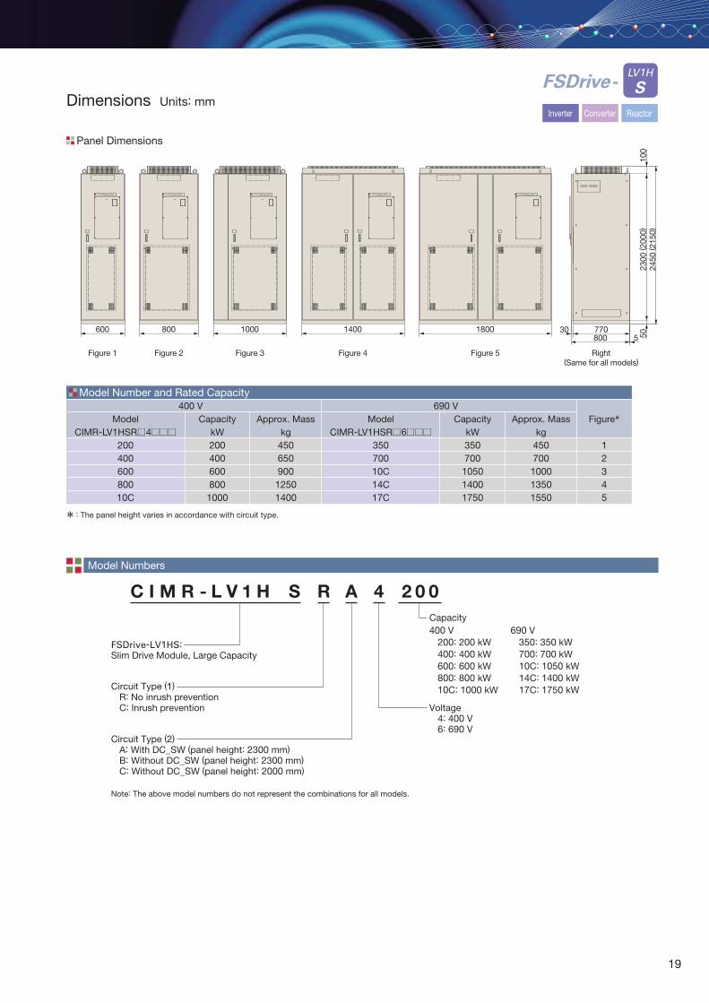
C I M R - L V 1 H S R A 4 2 0 0
FSDrive-LV1HS:Slim Drive Module, Large Capacity
Voltage 4: 400 V 6: 690 V
Circuit Type (1) R: No inrush prevention C: Inrush prevention
Circuit Type (2) A: With DC_SW (panel height: 2300 mm) B: Without DC_SW (panel height: 2300 mm) C: Without DC_SW (panel height: 2000 mm)
Capacity
Model Numbers
Model Number and Rated Capacity
Panel Dimensions
Dimensions Units: mm
Figure 5Figure 4Figure 3Figure 2Figure 1
400 V 690 VCapacity
kW200400600800
1000
Approx. Masskg
450650900
12501400
CapacitykW350700105014001750
Approx. Masskg
450700100013501550
Figure*
12345
* The panel height varies in accordance with circuit type.:
400 V 200: 200 kW 400: 400 kW 600: 600 kW 800: 800 kW 10C: 1000 kW
690 V 350: 350 kW 700: 700 kW 10C: 1050 kW 14C: 1400 kW 17C: 1750 kW
FSDrive-LV1HYASKAWA FSDrive-LV1HYASKAWA FSDrive-LV1HYASKAWA FSDrive-LV1HYASKAWA FSDrive-LV1HYASKAWA
600 800 1000 1400 1800
Right(Same for all models)
2450
( 215
0)
77030800 5
2300
( 200
0)50
100
LV1H
SFSDrive-
Inverter Converter Reactor
ModelCIMR-LV1HSR 4
20040060080010C
ModelCIMR-LV1HSR 6
35070010C14C17C
Note: The above model numbers do not represent the combinations for all models.
19
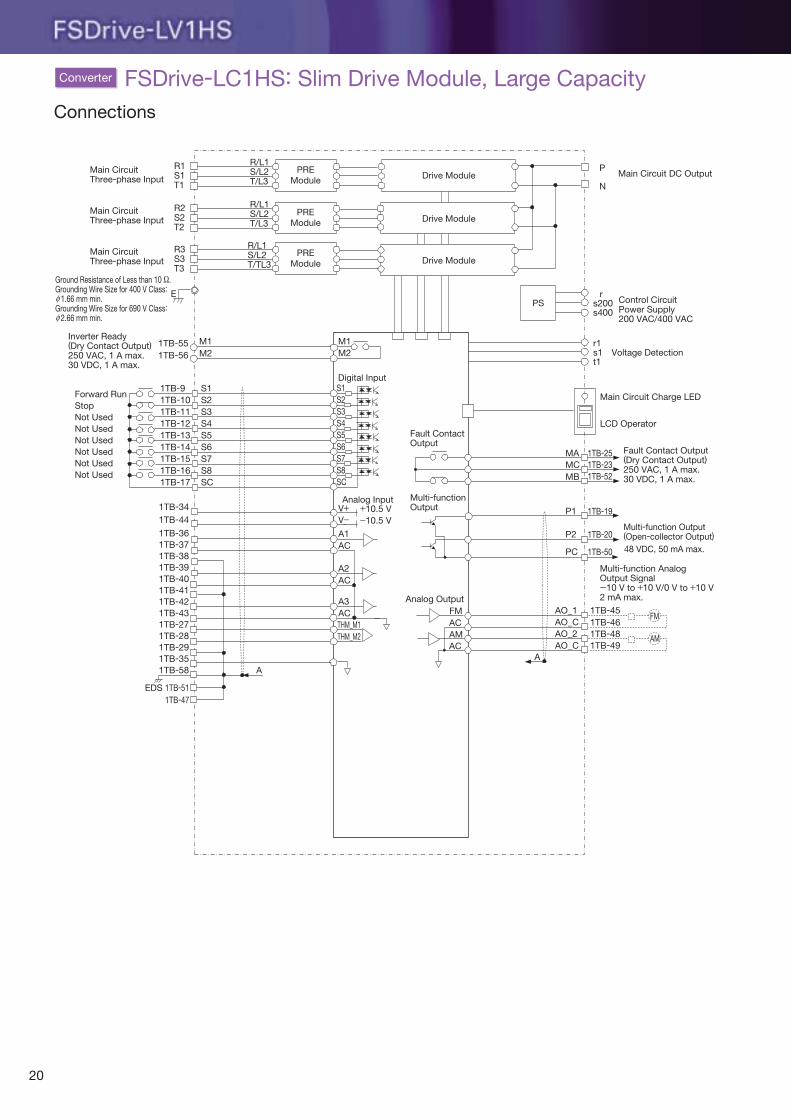
Connections
FSDrive-LC1HS: Slim Drive Module, Large Capacity
Main CircuitThree-phase Input
R1S1T1
R/L1S/L2T/L3
R/L1S/L2T/L3
R/L1S/L2T/TL3
R2S2T2
R3S3T3
1TB-551TB-56
1TB-9 S11TB-10 S21TB-11 S31TB-12 S41TB-13 S51TB-14 S61TB-15 S71TB-16 S81TB-17
1TB-341TB-441TB-361TB-371TB-381TB-391TB-401TB-411TB-421TB-431TB-271TB-28
1TB-351TB-29
1TB-58
EDS
A
1TB-511TB-47
SC
S1Digital Input
S2
M1M2
S3S4S5S6S7S8SC
A1AC
A2AC
A3ACTHM_M1THM_M2
M1M2
Main CircuitThree-phase Input
Main CircuitThree-phase Input
Forward Run
Inverter Ready (Dry Contact Output)250 VAC, 1 A max.30 VDC, 1 A max.
StopNot UsedNot UsedNot UsedNot UsedNot UsedNot Used
Analog Input+10.5 V−10.5 V
V+V−
Analog OutputFM
AMAC
AC
A
Multi-function Output (Open-collector Output)
P1
P2
PC
MB
MAMC
LCD Operator
Fault Contact Output (Dry Contact Output)250 VAC, 1 A max.30 VDC, 1 A max.
48 VDC, 50 mA max.
1TB-19
1TB-20
1TB-50
1TB-251TB-231TB-52
Main Circuit Charge LED
r1s1t1
Voltage Detection
rs200s400
Control CircuitPower Supply200 VAC/400 VAC
PS
P
NMain Circuit DC Output
Multi-function Analog Output Signal-10 V to +10 V/0 V to +10 V2 mA max.
AO_1
AO_2AO_C
1TB-45
1TB-481TB-49
AO_C 1TB-46FM
AM
Drive ModulePRE
Module
PREModule
PREModule
Drive Module
Drive Module
E
Converter
Ground Resistance of Less than 10 Ω.Grounding Wire Size for 400 V Class: 1.66 mm min.Grounding Wire Size for 690 V Class: 2.66 mm min.
ϕ
ϕ
Fault ContactOutput
Multi-functionOutput
20
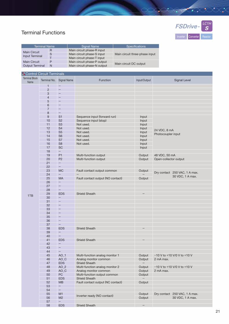
Terminal Functions
Terminal NameRSTPN
Signal NameMain circuit phase-R inputMain circuit phase-S inputMain circuit phase-T inputMain circuit phase-P outputMain circuit phase-N output
Specifications
Main circuit three-phase input
Main circuit DC output
Control Circuit Terminals
Main CircuitInput Terminal
Main CircuitOutput Terminal
LC1H
SFSDrive-
Inverter Converter Reactor
Terminal Block Name
1TB
Terminal No.
12345678910111213141516171819202122232425262728293031323334353637383940414243444546474849505152535455565758
Signal Name
--------S1S2S3S4S5S6S7S8SC-P1P2--MC-MA---EDS--------EDS--EDS---AO_1AO_CEDSAO_2AO_CPCEDSMB--M1M2-EDS
Input/Output
InputInputInputInputInputInputInputInputInput
OutputOutput
Output-
Output
-
-
-
OutputOutput-
OutputOutputOutput-
Output
OutputOutput
-
Function
Sequence input (forward run)Sequence input (stop)Not used.Not used.Not used.Not used.Not used.Not used.
Multi-function outputMulti-function output
Fault contact output common-Fault contact output (NO contact)
Shield Sheath
Shield Sheath
Shield Sheath
Multi-function analog monitor 1Analog monitor commonShield SheathMulti-function analog monitor 2Analog monitor commonMulti-function output commonShield SheathFault contact output (NC contact)
Inverter ready (NO contact)
Shield Sheath
Signal Level
24 VDC, 8 mAPhotocoupler input
48 VDC, 50 mAOpen-collector output
Dry contact 250 VAC, 1 A max.30 VDC, 1 A max.
−10 V to +10 V/0 V to +10 V2 mA max.
−10 V to +10 V/0 V to +10 V2 mA max.
Dry contact 250 VAC, 1 A max.30 VDC, 1 A max.
21
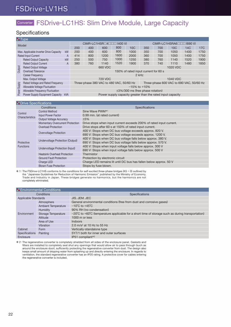
ControlCharacteristics
ProtectiveFunctions
ConditionsControl MethodInput Power FactorOutput Voltage AccuracyMomentary Overcurrent ProtectionOverload Protection
Overvoltage Protection
Undervoltage Protection (Output)
Undervoltage Protection (Input)
Heatsink Overheat ProtectionGround Fault ProtectionCharge LEDBlown Fuse Protection
SpecificationsSine Wave PWM*1
0.99 min. (at rated current)±5%Drive stops when input current exceeds 200% of rated input current.Drive stops after 60 s at 150% of rated input current.400 V: Stops when DC bus voltage exceeds approx. 820 V.690 V: Stops when DC bus voltage exceeds approx. 1200 V.400 V: Stops when DC bus voltage falls below approx. 380 V.690 V: Stops when DC bus voltage falls below approx. 570 V.400 V: Stops when input voltage falls below approx. 300 V690 V: Stops when input voltage falls below approx. 500 VThermistorProtection by electronic circuitCharge LED remains lit until DC bus has fallen below approx. 50 VStops by fuse blown.
ConditionsApplicable Standards
Environment
CabinetSpecificationsEnclosure
AtmosphereAmbient TemperatureHumidityStorage TemperatureAltitudeArea of UseVibrationFormPainting
SpecificationsJIS, JEM, JECGeneral environmental conditions (free from dust and corrosive gases)−10˚C to +45˚C90% RH (no condensation)−20˚C to +60˚C (temperature applicable for a short time of storage such as during transportation)1000 m or lessIndoors2.0 m/s2 at 10 Hz to 55 HzVertically-standalone type5Y7/1 both for inner and outer surfacesIP51 compliant*2
Drive Specifications
Environmental Conditions
Max. Applicable Inverter Drive CapacityRated Input Current
Model200200414250380
CIMR-LC1HSR 4 (400 V) CIMR-LC1HSRA6 (690 V)
660 VDC
720 VDCThree-phase 380 VAC to 480 VAC, 50/60 Hz
1020 VDC
1040 VDCThree-phase 600 VAC to 690 VAC, 50/60 Hz
400400800500760
60060012007501140
800800160010001520
10C1000200012501900
350350360380370
700700700760740
10C1050105011401110
14C1400140015201480
17C1750175019001850
kWA
kWA
kVA
Rated Output CapacityRated Output CurrentRated Output VoltageOverload ToleranceCareer FrequencyMax. Output VoltageRated Voltage and Rated FrequencyAllowable Voltage FluctuationAllowable Frequency FluctuationPower Supply Equipment Capacity
150% of rated input current for 60 s2 kHz
−15% to +10%±3%/300 ms (free phase rotation)
Power supply capacity greater than the rated input capacity
Type
Specifications
FSDrive-LC1HS: Slim Drive Module, Large CapacityConverterPo
wer S
uppl
yO
utpu
t
* The regenerative converter is completely shielded from all sides of the enclosure panel. Gaskets and filters are installed to completely seal shut any openings that would allow air to pass through (such as around the enclosure door), sufficiently protecting the regenerative converter from dust. The design also keeps small amount of dripping water from splashing up and directly entering the enclosure. In regards to ventilation, the standard regenerative converter has an IP20 rating. A protective cover for cables entering the regenerative converter is included.
:2
* The FSDrive-LC1HS conforms to the conditions for self-excited three-phase bridges (K5 = 0) outlined by the “Japanese Guidelines for Reduction of Harmonic Emission” published by the Ministry of Economy, Trade and Industry in Japan. These bridges generate no harmonics, but the harmonics are not completely eliminated.
1:
22
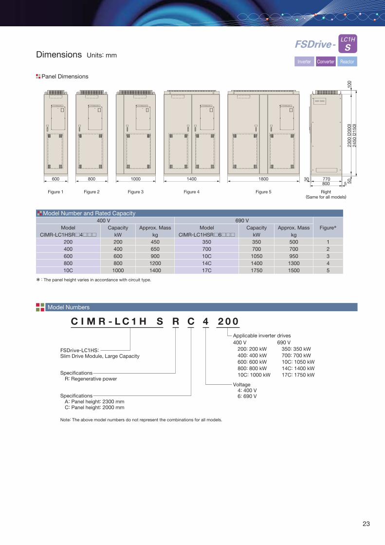
C I M R - L C 1 H S R C 4 2 0 0
FSDrive-LC1HS: Slim Drive Module, Large Capacity
Voltage 4: 400 V 6: 690 V
Specifications R: Regenerative power
Specifications A: Panel height: 2300 mm C: Panel height: 2000 mm
Applicable inverter drives
Model Numbers
Panel Dimensions
Right(Same for all models)
Figure 5Figure 4Figure 3Figure 2Figure 1
FSDrive-
* The panel height varies in accordance with circuit type.:
400 V 200: 200 kW 400: 400 kW 600: 600 kW 800: 800 kW 10C: 1000 kW
690 V 350: 350 kW 700: 700 kW 10C: 1050 kW 14C: 1400 kW 17C: 1750 kW
FSDrive-LV1HYASKAWA FSDrive-LV1HYASKAWA FSDrive-LV1HYASKAWA FSDrive-LV1HYASKAWA FSDrive-LV1HYASKAWA
600 800 1000 1400 1800
2450
( 215
0)
77030800 5
2300
( 200
0)50
100
LC1H
S
Model Number and Rated Capacity
ModelCIMR-LC1HSR 6
35070010C14C17C
ModelCIMR-LC1HSR 4
20040060080010C
400 V 690 VCapacity
kW200400600800
1000
Approx. Masskg
450650900
12001400
CapacitykW350700105014001750
Approx. Masskg
50070095013001500
Figure*
12345
Inverter Converter ReactorDimensions Units: mm
Note: The above model numbers do not represent the combinations for all models.
23
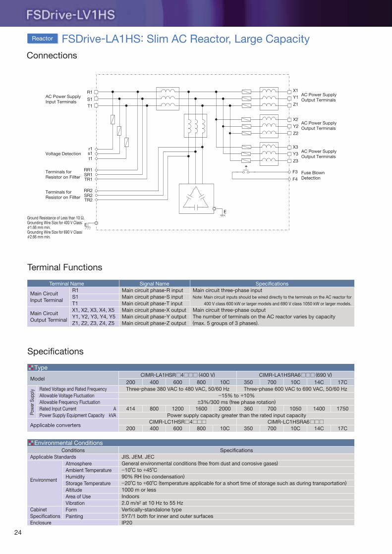
Connections
Terminal Functions
Terminal Name Signal NameMain circuit phase-R inputMain circuit phase-S inputMain circuit phase-T inputMain circuit phase-X outputMain circuit phase-Y outputMain circuit phase-Z output
SpecificationsMain circuit three-phase inputNote: Main circuit inputs should be wired directly to the terminals on the AC reactor for
400 V class 600 kW or larger models and 690 V class 1050 kW or larger models.
Main circuit three-phase outputThe number of terminals on the AC reactor varies by capacity(max. 5 groups of 3 phases).
Main CircuitInput Terminal
Main CircuitOutput Terminal
Specifications
ConditionsApplicable Standards
Environment
CabinetSpecificationsEnclosure
AtmosphereAmbient TemperatureHumidityStorage TemperatureAltitudeArea of UseVibrationFormPainting
SpecificationsJIS, JEM, JECGeneral environmental conditions (free from dust and corrosive gases)−10˚C to +45˚C90% RH (no condensation)−20˚C to +60˚C (temperature applicable for a short time of storage such as during transportation)1000 m or lessIndoors2.0 m/s2 at 10 Hz to 55 HzVertically-standalone type5Y7/1 both for inner and outer surfacesIP20
Environmental Conditions
Applicable converters
Model200
CIMR-LA1HSR 4 (400 V) CIMR-LA1HSRA6 (690 V)
400 600 800 10C 350 700 10C 14C 17C
414 800 1200 1600 2000 360 700 1050 1400 1750
200 400 600 800 10C 350 700 10C 14C 17C
AkVA
Rated Voltage and Rated FrequencyAllowable Voltage FluctuationAllowable Frequency FluctuationRated Input CurrentPower Supply Equipment Capacity
−15% to +10%±3%/300 ms (free phase rotation)
Power supply capacity greater than the rated input capacity
Type
FSDrive-LA1HS: Slim AC Reactor, Large Capacity
T1
R1
S1
X1
Y1
Z1
X2
Y2
Z2
X3
Y3
Z3
E
r1s1t1
RR1SR1TR1
RR2SR2TR2
F3
F4
E
AC Power SupplyInput Terminals
Voltage Detection
Terminals forResistor on Fillter
Terminals forResistor on Fillter
AC Power SupplyOutput Terminals
AC Power SupplyOutput Terminals
AC Power SupplyOutput Terminals
Fuse BlownDetection
Reactor
Ground Resistance of Less than 10 Ω.Grounding Wire Size for 400 V Class: 1.66 mm min.Grounding Wire Size for 690 V Class: 2.66 mm min.
ϕ
ϕ
R1S1T1X1, X2, X3, X4, X5Y1, Y2, Y3, Y4, Y5Z1, Z2, Z3, Z4, Z5
Pow
er S
uppl
y Three-phase 380 VAC to 480 VAC, 50/60 Hz Three-phase 600 VAC to 690 VAC, 50/60 Hz
CIMR-LC1HSR 4 CIMR-LC1HSRA6
24
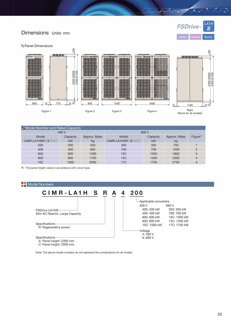
LA1H
SFSDrive-Dimensions Units: mm
Model Numbers
Panel Dimensions
* The panel height varies in accordance with circuit type.:
Model Number and Rated Capacity
ModelCIMR-LA1HSR 6
35070010C14C17C
ModelCIMR-LA1HSR 4
20040060080010C
400 V 690 VCapacity
kW200400600800
1000
Approx. Masskg
550850
130017002000
CapacitykW350700105014001750
Approx. Masskg
7501200180023002750
Figure*
12344
C I M R - L A 1 H S R A 4 2 0 0
FSDrive-LA1HS:Slim AC Reactor, Large Capacity
Voltage 4: 400 V 6: 690 V
Specifications R: Regenerative power
Specifications A: Panel height: 2300 mm C: Panel height: 2000 mm
Applicable converters400 V 200: 200 kW 400: 400 kW 600: 600 kW 800: 800 kW 10C: 1000 kW
690 V 350: 350 kW 700: 700 kW 10C: 1050 kW 14C: 1400 kW 17C: 1750 kW
Figure 1
800 770 3232
2450
( 215
0)23
00 ( 2
000)
5010
0
Figure 2
800
Figure 3
1400
Right(Same for all models)
2450
( 215
0)
32 1180 32
2300
( 200
0)50
100
Figure 4
1600
Inverter Converter Reactor
Note: The above model numbers do not represent the combinations for all models.
25
FSDrive-LV1H SERIES
YASKAWA ELECTRIC CORPORATION
In the event that the end user of this product is to be the military and said product is to be employed in any weapons systems or the manufacture thereof, the export will fall under the relevant regulations as stipulated in the Foreign Exchange and Foreign Trade Regulations. Therefore, be sure to follow all procedures and submit all relevant documentation according to any and all rules, regulations and laws that may apply.
Specifications are subject to change without notice for ongoing product modifications and improvements.
© 2009-2014 YASKAWA ELECTRIC CORPORATION. All rights reserved.
LITERATURE NO. KAEP C710691 00DPublished in Japan October 2014 09-4 5 -014-7-23-A
TOKYO OFFICENew Pier Takeshiba South Tower, 1-16-1, Kaigan, Minatoku, Tokyo 105-6891, JapanPhone 81-3-5402-4502 Fax 81-3-5402-4580http://www.yaskawa.co.jp
YASKAWA AMERICA, INC.2121 Norman Drive South, Waukegan, IL 60085, U.S.A.Phone 1-800-YASKAWA (927-5292) or 1-847-887-7000 Fax 1-847-887-7310http://www.yaskawa.com
YASKAWA ELÉTRICO DO BRASIL LTDA.Avenida Piraporinha 777, Diadema, São Paulo, 09950-000, BrazilPhone 55-11-3585-1100 Fax 55-11-3585-1187http://www.yaskawa.com.br
YASKAWA ELECTRIC KOREA CORPORATION9F, Kyobo Securities Bldg., 26-4, Yeouido-dong, Yeongdeungpo-gu, Seoul, 150-737, KoreaPhone 82-2-784-7844 Fax 82-2-784-8495http://www.yaskawa.co.kr
YASKAWA ELECTRIC (SINGAPORE) PTE. LTD.151 Lorong Chuan, #04-02A, New Tech Park 556741, SingaporePhone 65-6282-3003 Fax 65-6289-3003http://www.yaskawa.com.sg
YASKAWA ELECTRIC (CHINA) CO., LTD.22F, One Corporate Avenue, No.222 Hubin Road, Huangpu District, Shanghai 200021, ChinaPhone 86-21-5385-2200 Fax 86-21-5385-3299http://www.yaskawa.com.cn
YATEC ENGINEERING CORPORATIONNo.34, Sihyuan Rd., Sinjhuang City, Taipei Country 242, TaiwanPhone 886-2-6635-7030 Fax 886-2-6635-7010
Related Documents