LOW VELOCITY IMPACT BEHAVIOUR OF FIBER METAL LAMINATES A PROJECT REPORT Submitted by CB.EN.U4AEE09002 ADARSH HARIPRASAD CB.EN.U4AEE09019 MANOJ SHANMUGHOM CB.EN.U4AEE09027 NIKHIL MOHAN CB.EN.U4AEE09061 LALITYA DHAVALA In partial fulfillment of the award of the degree of BACHELOR OF TECHNOLOGY IN DEPARTMENT OF AEROSPACE ENGINEERING

Welcome message from author
This document is posted to help you gain knowledge. Please leave a comment to let me know what you think about it! Share it to your friends and learn new things together.
Transcript
LOW VELOCITY IMPACT BEHAVIOUR
OF FIBER METAL LAMINATES
A PROJECT REPORT
Submitted by
CB.EN.U4AEE09002 ADARSH HARIPRASAD
CB.EN.U4AEE09019 MANOJ SHANMUGHOM
CB.EN.U4AEE09027 NIKHIL MOHAN
CB.EN.U4AEE09061 LALITYA DHAVALA
In partial fulfillment of the award of the degree of
BACHELOR OF TECHNOLOGY
IN
DEPARTMENT OF AEROSPACE ENGINEERING
This is to certify that the thesis entitled ‘LOW VELOCITY IMPACT BEHAVIOUR OF
FIBER METAL LAMINATES’ submitted by
CB.EN.U4AEE09002 ADARSH HARIPRASAD
CB.EN.U4AEE09019 MANOJ SHANMUGHOM
CB.EN.U4AEE09027 NIKHIL MOHAN
CB.EN.U4AEE09061 LALITYA DHAVALA
In partial fulfillment of the requirement for the award of the Degree of Bachelor of Technology
in AEROSPACE ENGINEERING is a bonafide record of the work carried out under my
guidance and supervision at the Amrita School of Engineering, Ettimadai, Coimbatore
(SIGNATURE)
Dr. V. Sivakumar
(Project Guide)
Associate Professor
Department of Aerospace Engineering
This report was evaluated by us on :
INTERNAL EXAMINER EXTERNAL EXAMINER
AMRITA VISHWA VIDYAPEETHAM
AMRITA SCHOOL OF ENGINEERING, COIMBATORE - 641105
DEPARTMENT OF AEROSPACE ENGINEERING
DECLARATION
We, ADARSH HARIPRASAD (CB.EN.U4AEE09002), MANOJ SHANMUGHOM
(CB.EN.U4AEE09019), NIKHIL MOHAN (CB.EN.U4AEE09027) and LALITYA DHAVALA
(CB.EN.U4AEE09061) hereby declare that this project report entitled ‘LOW VELOCITY
IMPACT BEHAVIOUR OF FIBER METAL LAMINATES’ , is a record of original work done
by us under the guidance of Dr. V. Sivakumar, Associate Professor, Department of Aerospace
Engineering, Amrita School of Engineering, Coimbatore. This work has not formed the basis of
any degree/ diploma/ fellowship or a similar award to any candidate in any university, to the best
of our knowledge.
ADARSH HARIPRASAD
MANOJ SHANMUGHOM
NIKHIL MOHAN
LALITYA DHAVALA
Place: Coimbatore
Date:
COUNTERSIGNED:
( SIGNATURE)
Dr. V. Sivakumar
( Project Guide )
Associate Professor
Department of Aerospace Engineering
Amrita School of Engineering
Ettimadai , Coimbatore.
i
ACKNOWLEDGEMENT
Firstly, we express our sincere thanks to Dr.J.Chandrasekhar, Chairman, Department of
Aerospace Engineering, for giving us an opportunity to do this project.
Then, we express our heartfelt gratitude to our project guide, Dr. V. Sivakumar, Associate
Professor, Department of Aerospace Engineering. The motivation and inspiration that he
provided to us were just an added benefit to the invaluable guidance and support that he has
given throughout the duration of the project. He has kindly cleared all the doubts and queries that
we had without which we wouldn’t have been able to complete this project.
We thank the entire faculty who have supported us with immense knowledge and helped us
always.
We are also grateful to our friends and parents who were always there for us with encouraging
words and generous wisdom.
Finally, we thank the Almighty, who though in different forms, has showered us with His
blessings, strength and courage to complete this project.
ii
ABSTRACT
Fiber Metal Laminates are a class of hybrid composites which are layers of metal and fibre
reinforced composites stacked alternatively together. These materials are being increasingly used
in the aircraft industry in the form of fuselage skins, wing skins and cargo floors. Impact loading
behaviour has to be analyzed because it forms an important load factor on the cargo floors.
The main objective of this project was to analyze the behavior of a FML under low velocity
impact load. For this, a FML of Aluminum/ Glass Fiber Reinforced Polymer/Aluminum was
considered and modeled in ABAQUS. Pre-processing, analysis and post processing were
performed in ABAQUS CAE itself. The study was repeated for different orientations of the
fibers of GFRP and the results were compared.
The stress variation across the thickness for all the three configurations considered was studied.
Then using appropriate failure criteria, the maximum load that can be taken by the FML plate
was compared to the maximum load that the pure metal plate can sustain. It was found that FML
offers higher strength to weight ratio. This result was then extended to find the maximum weight
of the projectile that can be dropped onto a hypothetical cabin floor made of the FML
considered.
iii
TABLE OF CONTENTS
ACKNOWLEDGEMENT i
ABSTRACT ii
TABLE OF CONTENTS iii
LIST OF FIGURES v
LIST OF TABLES vi
LIST OF SYMBOLS AND NOTATIONS vii
1. INTRODUCTION 1
1.1 BACKGROUND INFORMATION 1
1.2 FIBER METAL LAMINATES 2
1.3 IMPACT LOADING 5
2. LITERATURE REVIEW 8
3. FINITE ELEMENT MODELLING 9
3.1 INTRODUCTION TO FINITE ELEMENT ANALYSIS 9
3.2 VALIDATION OF ABAQUS RESULTS FOR THE PRESENT 10
CASE
3.3 MODELLING OF FML IN ABAQUS 13
3.4 STRESS VARIATION IN FML 15
3.5 FAILURE CRITERIA MODELLING 16
4. RESULTS AND DISCUSSION 18
4.1 MAXIMUM STRESS EXPERIENCED BY THE FML 18
4.2 FAILURE BEHAVIOUR 19
4.3 COMPARISON OF ALUMINIUM vs. FML 20
4.4 APPLICATION 21
4.5 LIMITATIONS 21
iv
5. CONCLUSION 22
6. REFERENCE viii
7. APPENDIX x
v
LIST OF FIGURES
Fig 1.1 Usage of composites in aircrafts 1
Fig 1.2 Fiber Metal Laminates 2
Fig 1.3 Impact behavior of GLARE 2
Fig 1.4 Improved fatigue behavior of GLARE 3
Fig 1.5 Residual strength diagram of aluminum 3
Vs. GLARE
Fig 1.6 Usage of different types of composites 5
in the aircraft industry
Fig 1.7 Use of FMLs in A380 5
Fig 1.8 Areas on aircraft where impact loading 6
has to be investigated
Fig 3.1 Deformed shape of Aluminum plate 10
Fig 3.2 Deformed shape of GFRP plate 11
Fig 3.3 (a) Specimen of FML used 13
Fig 3.3(b) Layup depicting two aluminum layers 14
and one GFRP layer
Fig 3.4 Variation of stress across thickness 16
Fig 4.1 von Mises stress distribution of FML 18
Fig 4.2 Specimen made of Aluminum 19
Fig 4.3 S11 stress variation across thickness of 20
three different configurations considered
Fig 4.4 S13 stress variation across thickness of 20
three different configurations considered
vi
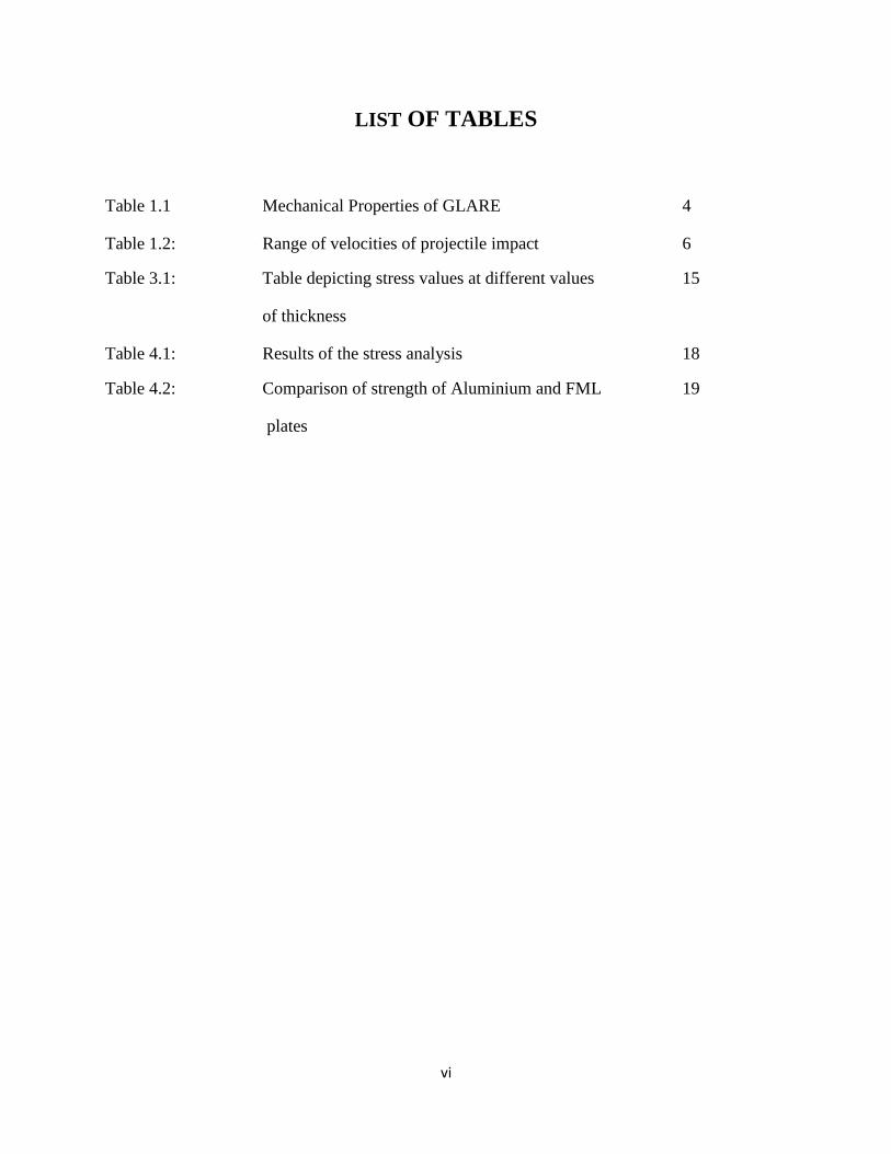
LIST OF TABLES
Table 1.1 Mechanical Properties of GLARE 4
Table 1.2: Range of velocities of projectile impact 6
Table 3.1: Table depicting stress values at different values 15
of thickness
Table 4.1: Results of the stress analysis 18
Table 4.2: Comparison of strength of Aluminium and FML 19
plates
vii
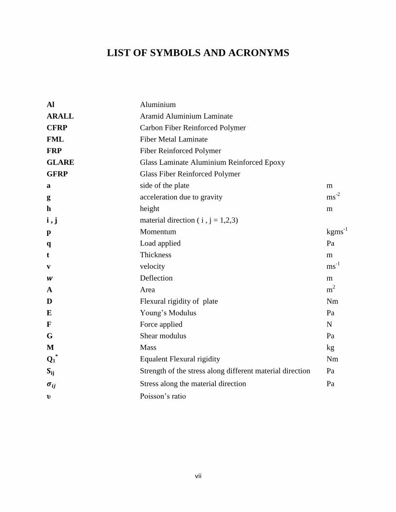
LIST OF SYMBOLS AND ACRONYMS
Al Aluminium
ARALL Aramid Aluminium Laminate
CFRP Carbon Fiber Reinforced Polymer
FML Fiber Metal Laminate
FRP Fiber Reinforced Polymer
GLARE Glass Laminate Aluminium Reinforced Epoxy
GFRP Glass Fiber Reinforced Polymer
a side of the plate m
g acceleration due to gravity ms-2
h height m
i , j material direction ( i , j = 1,2,3)
p Momentum kgms-1
q Load applied Pa
t Thickness m
v velocity ms-1
Deflection m
A Area m2
D Flexural rigidity of plate Nm
E Young’s Modulus Pa
F Force applied N
G Shear modulus Pa
M Mass kg
Q1* Equalent Flexural rigidity Nm
Strength of the stress along different material direction Pa
Stress along the material direction Pa
υ Poisson’s ratio
1
CHAPTER 1
INTRODUCTION
1.1 Background information:
Composite materials or composites, in short, are a combination of two or more materials
whose properties vary from the properties of its constituents. Examples of composite
materials are fibre reinforced polymers, ceramic composites and metal composites. Today
composites are extensively used in various industries such as construction, heavy structures
such as bridges and ships, race car bodies but the most advanced applications have been in
the aerospace industry. This has been attributed to their high strength to weight ratio, lesser
maintenance costs, improved corrosion resistance, better fatigue resistance, lesser thermal
expansion and tailor-able mechanical properties. The most commonly used composites in
aerospace are Fibre reinforced polymers of several types, like CFRP (Carbon FRP) and
GFRP (Glass FRP) .
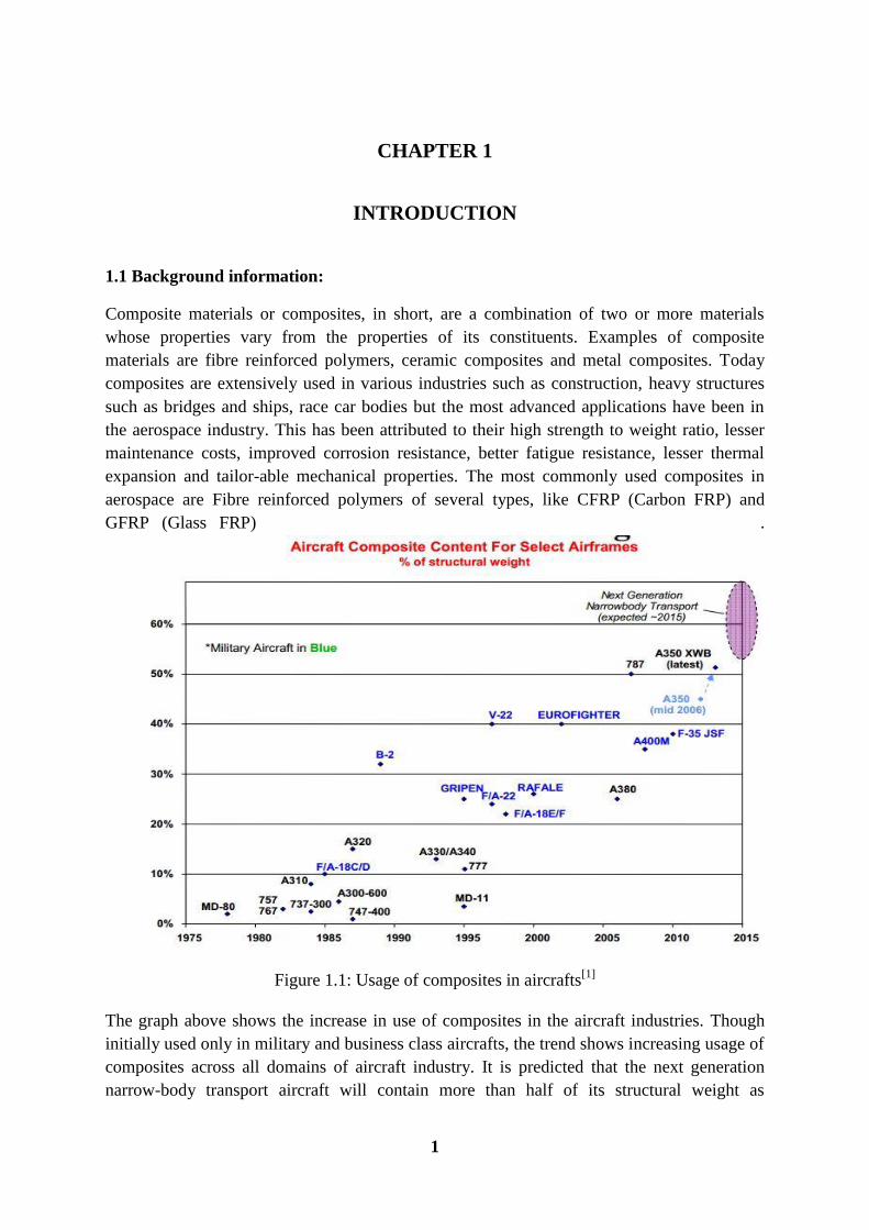
Figure 1.1: Usage of composites in aircrafts[1]
The graph above shows the increase in use of composites in the aircraft industries. Though
initially used only in military and business class aircrafts, the trend shows increasing usage of
composites across all domains of aircraft industry. It is predicted that the next generation
narrow-body transport aircraft will contain more than half of its structural weight as
2
composites. Currently, the Boeing 787 Dreamliner is the aircraft with maximum usage of
composites.
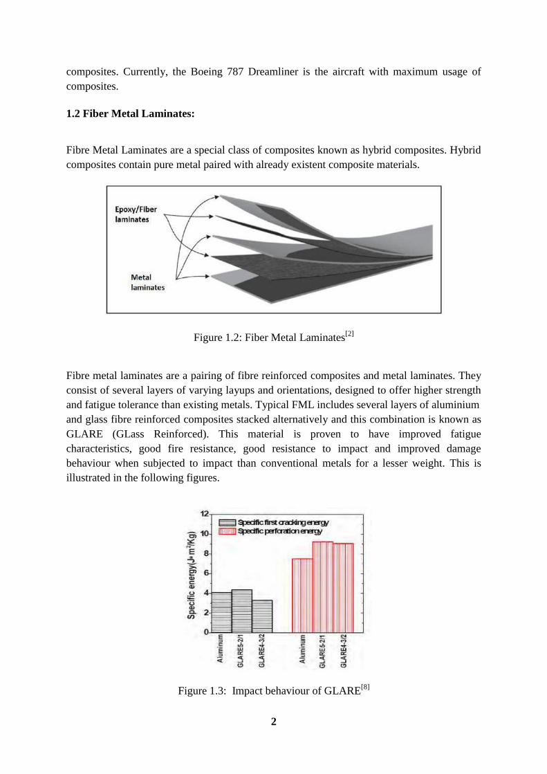
1.2 Fiber Metal Laminates:
Fibre Metal Laminates are a special class of composites known as hybrid composites. Hybrid
composites contain pure metal paired with already existent composite materials.
Figure 1.2: Fiber Metal Laminates[2]
Fibre metal laminates are a pairing of fibre reinforced composites and metal laminates. They
consist of several layers of varying layups and orientations, designed to offer higher strength
and fatigue tolerance than existing metals. Typical FML includes several layers of aluminium
and glass fibre reinforced composites stacked alternatively and this combination is known as
GLARE (GLass Reinforced). This material is proven to have improved fatigue
characteristics, good fire resistance, good resistance to impact and improved damage
behaviour when subjected to impact than conventional metals for a lesser weight. This is
illustrated in the following figures.
Figure 1.3: Impact behaviour of GLARE[8]
3
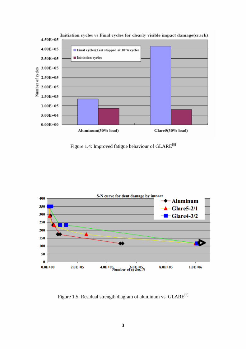
Figure 1.4: Improved fatigue behaviour of GLARE[8]
Figure 1.5: Residual strength diagram of aluminum vs. GLARE[8]
4
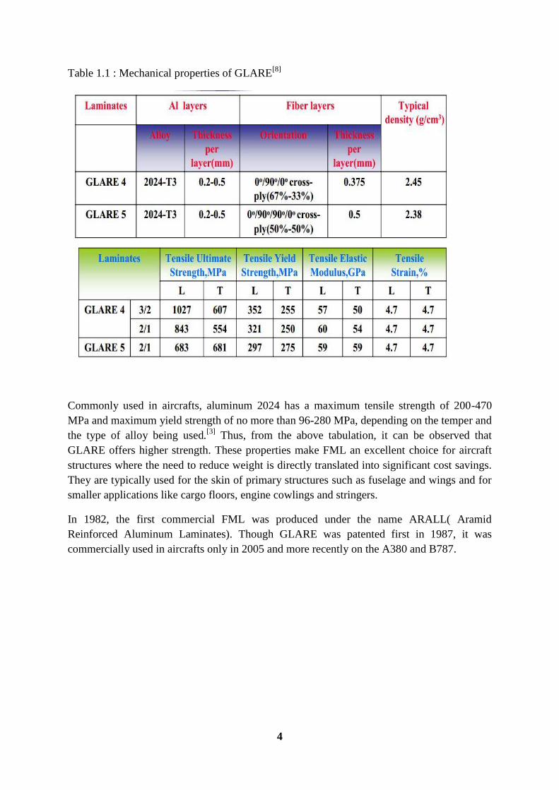
Table 1.1 : Mechanical properties of GLARE[8]
Commonly used in aircrafts, aluminum 2024 has a maximum tensile strength of 200-470
MPa and maximum yield strength of no more than 96-280 MPa, depending on the temper and
the type of alloy being used.[3]
Thus, from the above tabulation, it can be observed that
GLARE offers higher strength. These properties make FML an excellent choice for aircraft
structures where the need to reduce weight is directly translated into significant cost savings.
They are typically used for the skin of primary structures such as fuselage and wings and for
smaller applications like cargo floors, engine cowlings and stringers.
In 1982, the first commercial FML was produced under the name ARALL( Aramid
Reinforced Aluminum Laminates). Though GLARE was patented first in 1987, it was
commercially used in aircrafts only in 2005 and more recently on the A380 and B787.
5
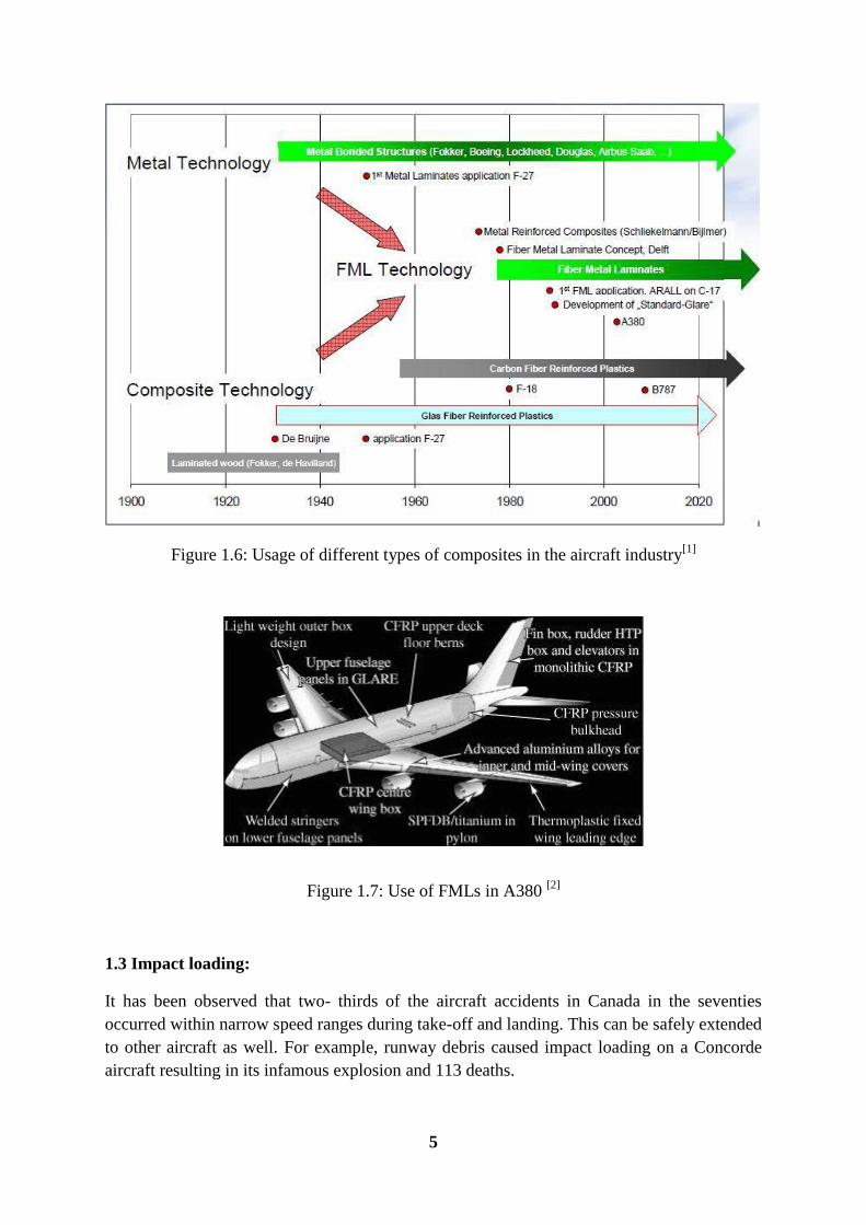
Figure 1.6: Usage of different types of composites in the aircraft industry[1]
Figure 1.7: Use of FMLs in A380 [2]
1.3 Impact loading:
It has been observed that two- thirds of the aircraft accidents in Canada in the seventies
occurred within narrow speed ranges during take-off and landing. This can be safely extended
to other aircraft as well. For example, runway debris caused impact loading on a Concorde
aircraft resulting in its infamous explosion and 113 deaths.
6
When crash data was throughout the world was analysed, low to medium velocity impact
loads were the most prominent ones.
Table 1.2: Range of velocities of projectile impact[10]
Description Energy
(J)
Mass
(g)
Velocity
(m/s)
Circumstances
Tool drop 6 330 6 Maintenance work
Removable element drop 4 220 6 Cargo handling
Maintenance component 16 910 6 Maintenance work
Hail(up to 51 mm diameter) 43 62 37.3 Take-off and landing,
flight, taxiing
Bird strike 3.8-81(kJ) 1800 65-300 Take-off and landing,
flight, taxiing
Runway debris 2-40 9 20-94 Take-off and landing,
flight, taxiing
Concentrated load 50 - Static Maintenance cargo
handling
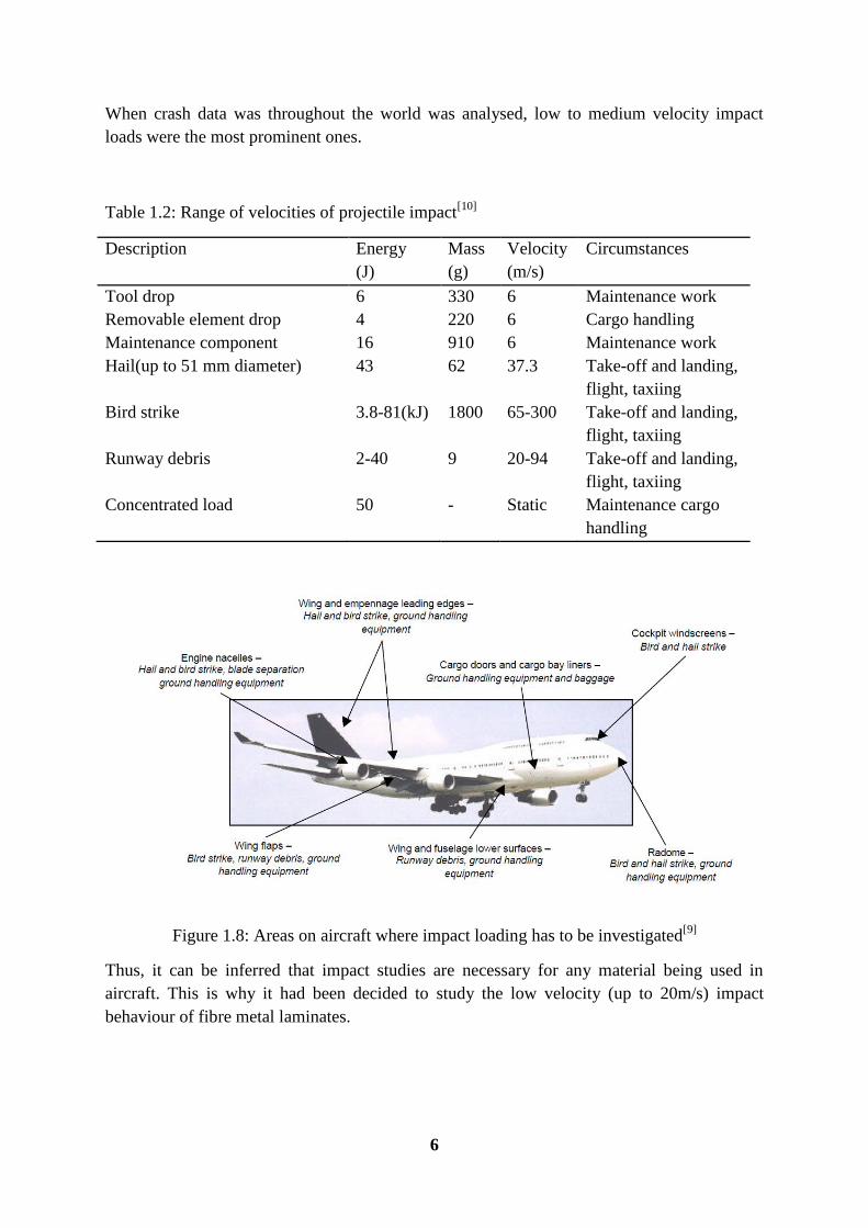
Figure 1.8: Areas on aircraft where impact loading has to be investigated[9]
Thus, it can be inferred that impact studies are necessary for any material being used in
aircraft. This is why it had been decided to study the low velocity (up to 20m/s) impact
behaviour of fibre metal laminates.
7
This study can be broadly performed in three categories:
1. Experimental study- most common. Numerous studies have been done on the low
velocity impact behaviour of different types of fibre metal laminates, generally using
drop weight impact apparatus and different specimens and impactors. Due to cost
limitations, this approach was not an option to a bachelors’ level project.
2. Analytical study-a failure model for the FML is proposed and compared with
experimental approach. Though many papers have been published in this area, there
has been no officially identified failure model for FML yet.
3. Numerical analysis- this is mainly through finite element analysis using soft-wares
like ABAQUS and LS-DYNA. ABAQUS Implicit was chosen for this project and
FML layers have been modelled in it.
8
CHAPTER 2
LITERATURE REVIEW
Several papers on the analysis of FML were studied and an overview of the current research
development in this field is presented below.
Studies on energy distribution in GLARE and 2024-T3 aluminium during low
velocity impact were conducted by F.D. Morinière, R.C. Alderliesten, and R.
Benedictus [4]
and in this; an analytical model was developed to predict the impact
behaviour of FMLs. Also, absorbed energy, impact force, maximum deflection and
impact velocity were predicted within 5% of test results. The conclusion of the papers
is that GLARE 5-2/1-0.4 is 72% more resistant than its monolithic 2024-T3
aluminium counterpart of the same thickness.
Studies on the low velocity impact resistance of aluminium/carbon-epoxy fibre metal
laminates were conducted by Jarosław bieniaś and Patryk jakubczak[5]
. This study
researches the resistance to low-velocity impact of hybrid laminates based on
aluminium alloys and a carbon/epoxy composite (Al/CFRP).The inter-relation
between the damage zone area, maximum depth of the deformation and the layer
configurations and energy level was investigated. It was noted that Al/CFRP
laminates have high impact damage resistance (at low-velocity) because of the
superior properties of both metals and fibrous composite materials with strong
adhesion bonding. In particular the FML with (0/90) ply sequence in the carbon fibre
was observed to have the best behaviour.
Numerical modelling of low-velocity impact damage in fibre-metal-laminates was
done by Jeremy Laliberté and Cheung Poon and Paul. V. Straznicky[9]
. The most
important part of this paper was the development of a user defined material subroutine
in LS-DYNA for the FRP in one type of FML and it was hence showed that
delamination is not a critical damage mode in FMLs under low velocity impact loads.
Low-velocity impact response of fibre–metal laminates was studied by both
experimental approach and finite element analysis by Shengqing Zhu and Gin Boay
Chai.[11]
The impact dynamic response and failure modes of fibre–metal laminated
panels subjected to low velocity impact were investigated and presented. The
experiments were conducted using a standard drop-weight test machine and the finite
element analysis was carried out using ABAQUS.
9
CHAPTER 3
FINITE ELEMENT MODELLING
3.1 Introduction to Finite Element Analysis:
Finite Element Analysis (FEA) was first developed in 1943 by R. Courant, who utilized
the Ritz method of numerical analysis and minimization of variational calculus to obtain
approximate solutions to vibration systems.
In practice, a finite element analysis usually consists of three principal steps:
Pre-processing: The user constructs a model of the part to be analysed in which the
geometry is divided into a number of discrete elements connected at discrete points
called nodes. This can be constructed using commercially available soft wares like
CAD, Hypermesh etc.
Analysis: The dataset prepared by the pre-processor is used as input to the finite
element code itself, which constructs and solves a system of linear or nonlinear
algebraic equations
Kijuij=fi
where u and f are the displacements and externally applied forces at the nodes.
The formation of the K matrix is dependent on the type of problem. Commercial codes
may have very large element libraries, with elements appropriate to a wide range of
problem types. One of FEA's principal advantages is that many problem types can be
addressed with the same code, merely by specifying the appropriate element types from
the library.
Post processing: A typical post-processor display overlays colored contours
representing stress levels on the model, showing a full-fledged picture similar to that of
photo-elastic or more experimental results.
10
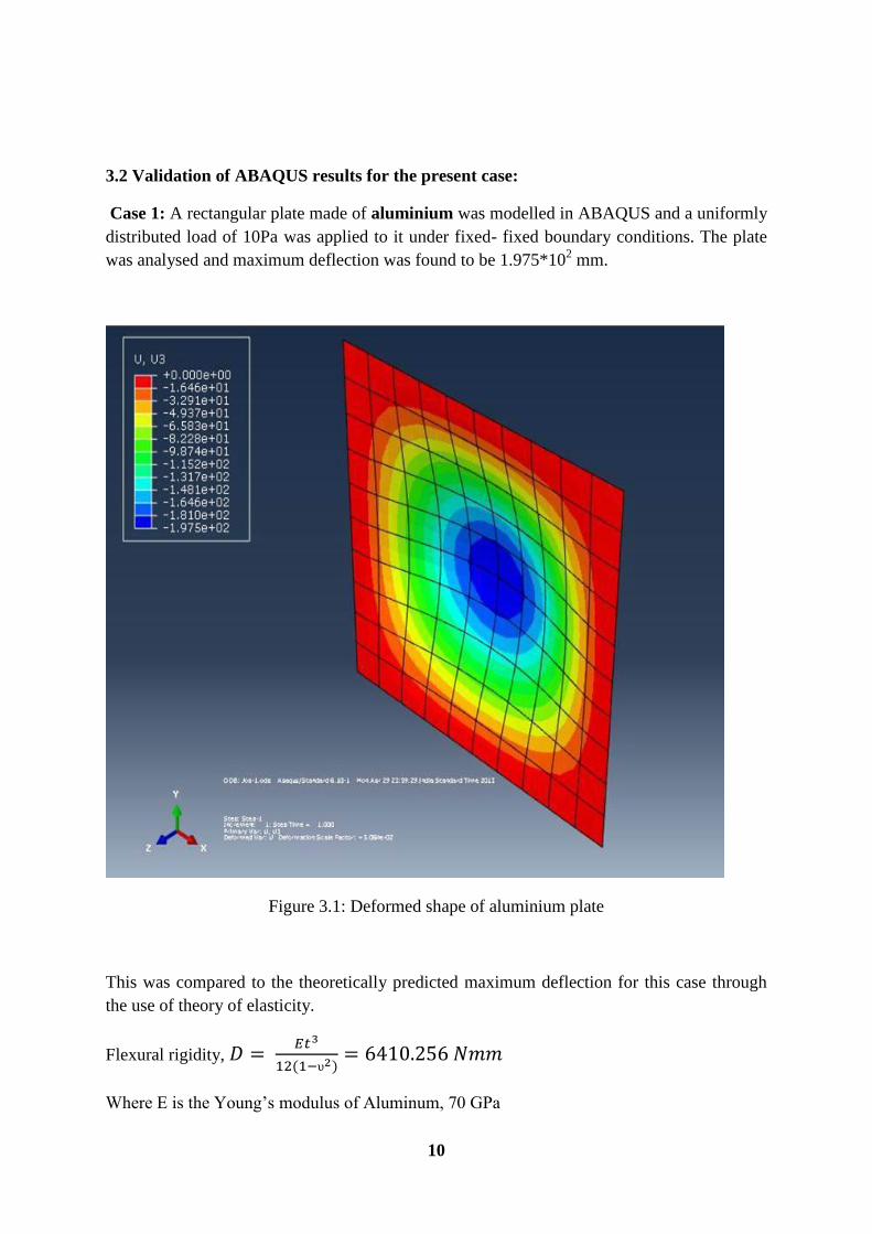
3.2 Validation of ABAQUS results for the present case:
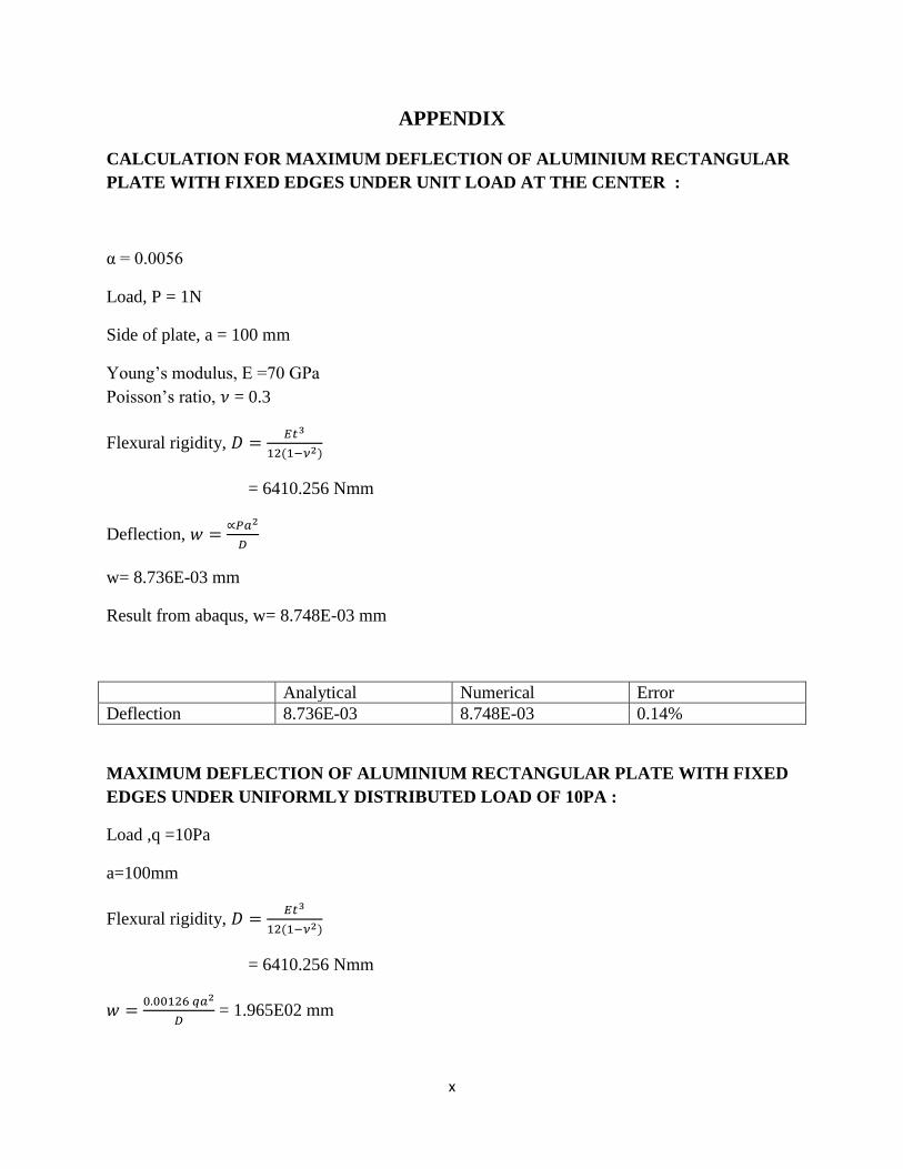
Case 1: A rectangular plate made of aluminium was modelled in ABAQUS and a uniformly
distributed load of 10Pa was applied to it under fixed- fixed boundary conditions. The plate
was analysed and maximum deflection was found to be 1.975*102 mm.
Figure 3.1: Deformed shape of aluminium plate
This was compared to the theoretically predicted maximum deflection for this case through
the use of theory of elasticity.
Flexural rigidity,
Where E is the Young’s modulus of Aluminum, 70 GPa
11
t is the thickness of aluminum plate, 3mm
υ is the Poisson’s ratio of Aluminum, 0.3
Maximum deflection,
Where q is the applied load, 10 Pa
a is the side of the plate, 100 mm
The error between the numerical and theoretical calculation was found to be 0.5%.
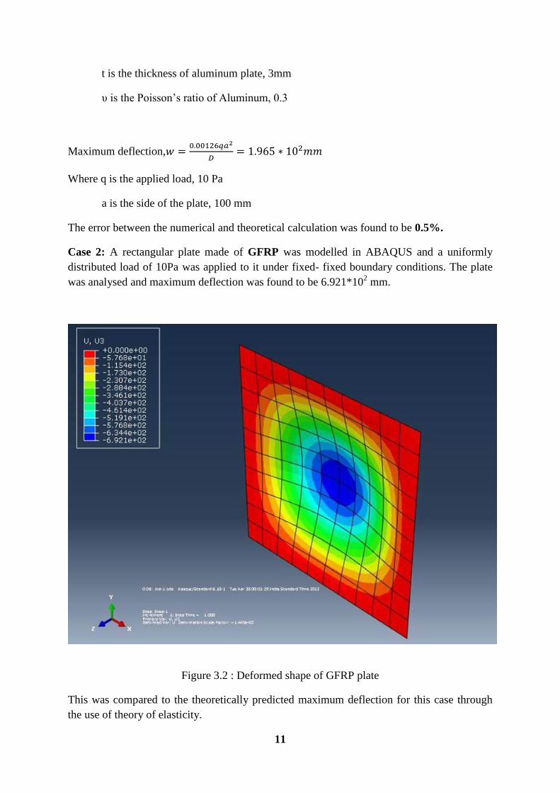
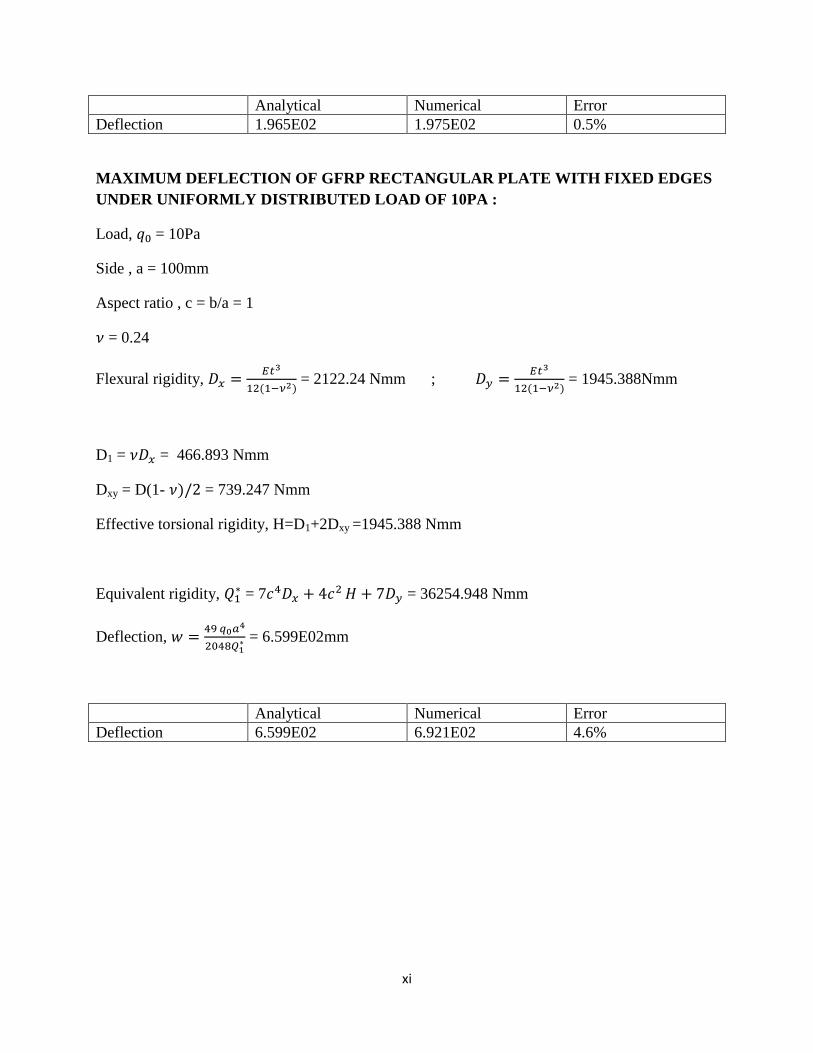
Case 2: A rectangular plate made of GFRP was modelled in ABAQUS and a uniformly
distributed load of 10Pa was applied to it under fixed- fixed boundary conditions. The plate
was analysed and maximum deflection was found to be 6.921*102 mm.
Figure 3.2 : Deformed shape of GFRP plate
This was compared to the theoretically predicted maximum deflection for this case through
the use of theory of elasticity.
12
Flexural rigidity,
D1 = νDx = 466.893 Nmm
Dxy = D(1-ν/2) =739.247 Nmm
Effective torsional rigidity, H=D1+2Dxy =1945.388 Nmm
Equivalent rigidity,Q1*
Deflection,
The error between the numerical and theoretical calculation was found to be 4.62%.
CONCLUSION: ABAQUS results were validated for the case in consideration and this can
be extended to the modeling of FML plates.
13
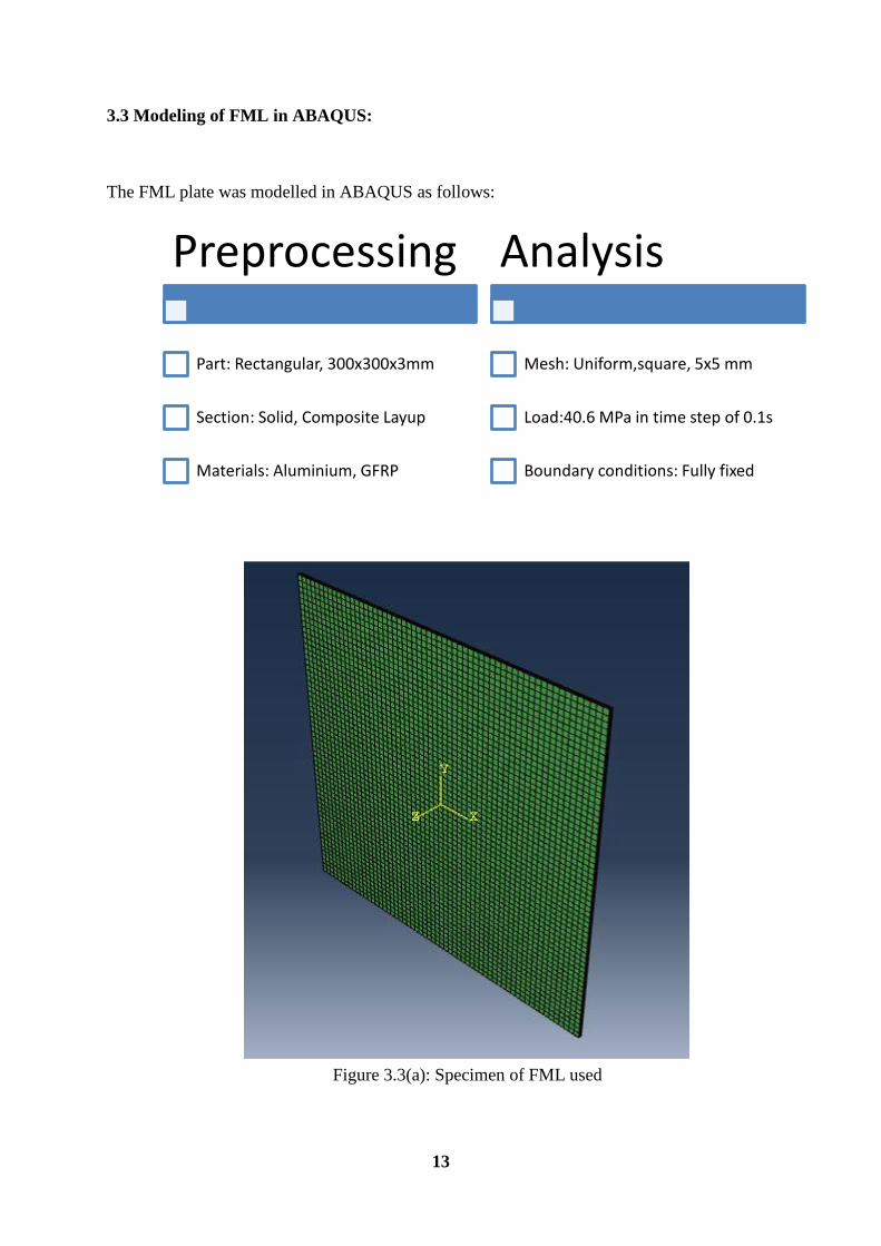
3.3 Modeling of FML in ABAQUS:
The FML plate was modelled in ABAQUS as follows:
Figure 3.3(a): Specimen of FML used
Preprocessing
Part: Rectangular, 300x300x3mm
Section: Solid, Composite Layup
Materials: Aluminium, GFRP
Analysis
Mesh: Uniform,square, 5x5 mm
Load:40.6 MPa in time step of 0.1s
Boundary conditions: Fully fixed
14
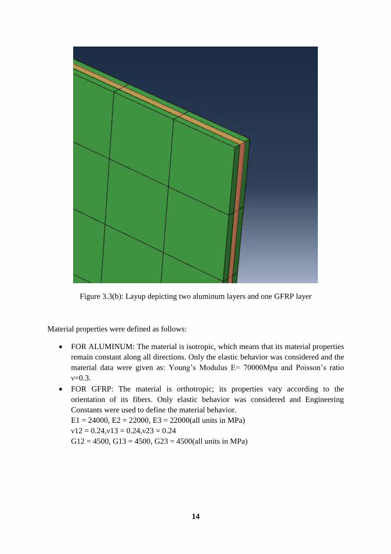
Figure 3.3(b): Layup depicting two aluminum layers and one GFRP layer
Material properties were defined as follows:
FOR ALUMINUM: The material is isotropic, which means that its material properties
remain constant along all directions. Only the elastic behavior was considered and the
material data were given as: Young’s Modulus E= 70000Mpa and Poisson’s ratio
ν=0.3.
FOR GFRP: The material is orthotropic; its properties vary according to the
orientation of its fibers. Only elastic behavior was considered and Engineering
Constants were used to define the material behavior.
E1 = 24000, E2 = 22000, E3 = 22000(all units in MPa)
ν12 = 0.24,ν13 = 0.24,ν23 = 0.24
G12 = 4500, G13 = 4500, G23 = 4500(all units in MPa)
15
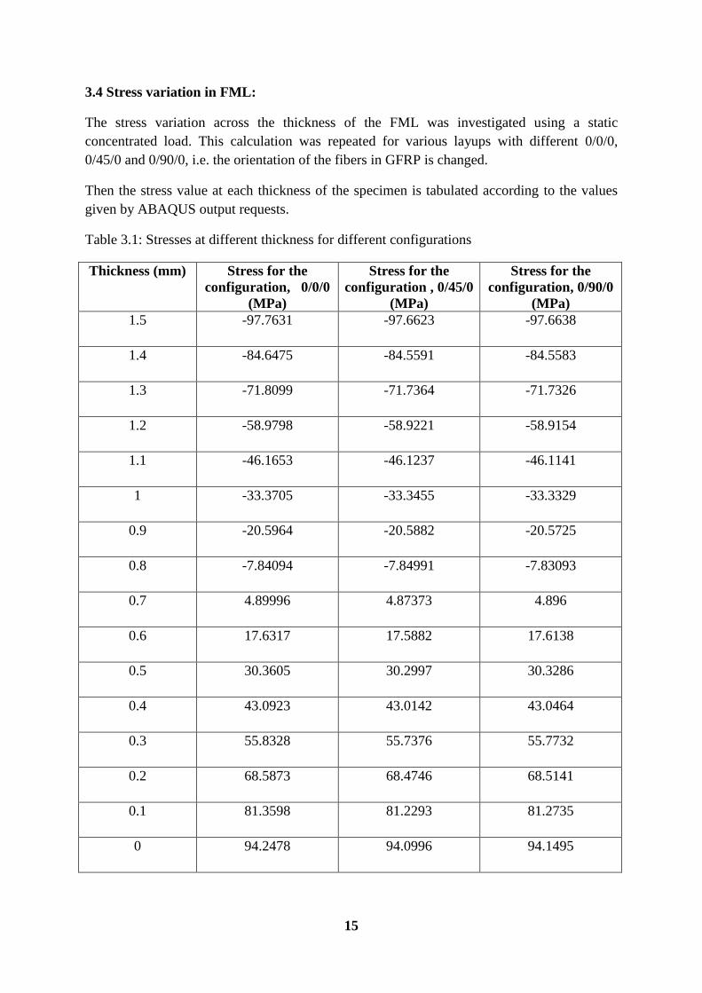
3.4 Stress variation in FML:
The stress variation across the thickness of the FML was investigated using a static
concentrated load. This calculation was repeated for various layups with different 0/0/0,
0/45/0 and 0/90/0, i.e. the orientation of the fibers in GFRP is changed.
Then the stress value at each thickness of the specimen is tabulated according to the values
given by ABAQUS output requests.
Table 3.1: Stresses at different thickness for different configurations
Thickness (mm)
Stress for the
configuration, 0/0/0
(MPa)
Stress for the
configuration , 0/45/0
(MPa)
Stress for the
configuration, 0/90/0
(MPa)
1.5 -97.7631 -97.6623 -97.6638
1.4 -84.6475 -84.5591 -84.5583
1.3 -71.8099 -71.7364 -71.7326
1.2 -58.9798 -58.9221 -58.9154
1.1 -46.1653 -46.1237 -46.1141
1 -33.3705 -33.3455 -33.3329
0.9 -20.5964 -20.5882 -20.5725
0.8 -7.84094 -7.84991 -7.83093
0.7 4.89996 4.87373 4.896
0.6 17.6317 17.5882 17.6138
0.5 30.3605 30.2997 30.3286
0.4 43.0923 43.0142 43.0464
0.3 55.8328 55.7376 55.7732
0.2 68.5873 68.4746 68.5141
0.1 81.3598 81.2293 81.2735
0 94.2478 94.0996 94.1495
16
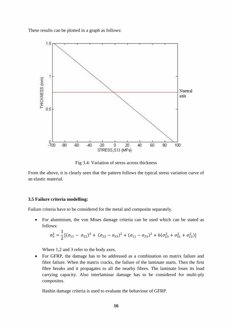
These results can be plotted in a graph as follows:
Fig 3.4: Variation of stress across thickness
From the above, it is clearly seen that the pattern follows the typical stress variation curve of
an elastic material.
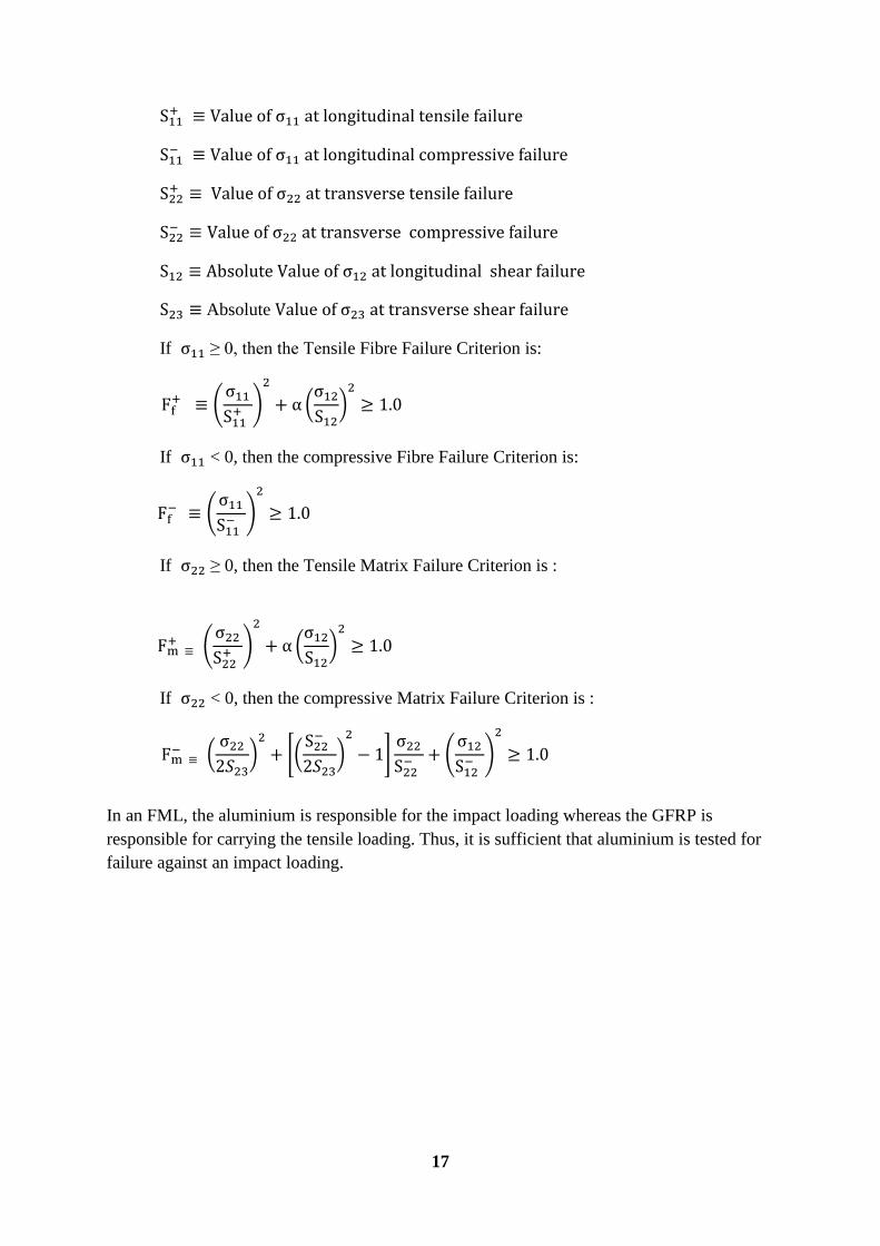
3.5 Failure criteria modelling:
Failure criteria have to be considered for the metal and composite separately.
For aluminium, the von Mises damage criteria can be used which can be stated as
follows:
Where 1,2 and 3 refer to the body axes.
For GFRP, the damage has to be addressed as a combination on matrix failure and
fibre failure. When the matrix cracks, the failure of the laminate starts. Then the first
fibre breaks and it propagates to all the nearby fibres. The laminate loses its load
carrying capacity. Also interlaminar damage has to be considered for multi-ply
composites.
Hashin damage criteria is used to evaluate the behaviour of GFRP.
17
Absolute
If ≥ 0, then the Tensile Fibre Failure Criterion is:
(
)
(
)
If < 0, then the compressive Fibre Failure Criterion is:
(
)
If ≥ 0, then the Tensile Matrix Failure Criterion is :
(
)
(
)
If < 0, then the compressive Matrix Failure Criterion is :
(
)
*(
)
+
(
)
In an FML, the aluminium is responsible for the impact loading whereas the GFRP is
responsible for carrying the tensile loading. Thus, it is sufficient that aluminium is tested for
failure against an impact loading.
18
CHAPTER 4
RESULTS AND DISCUSSION
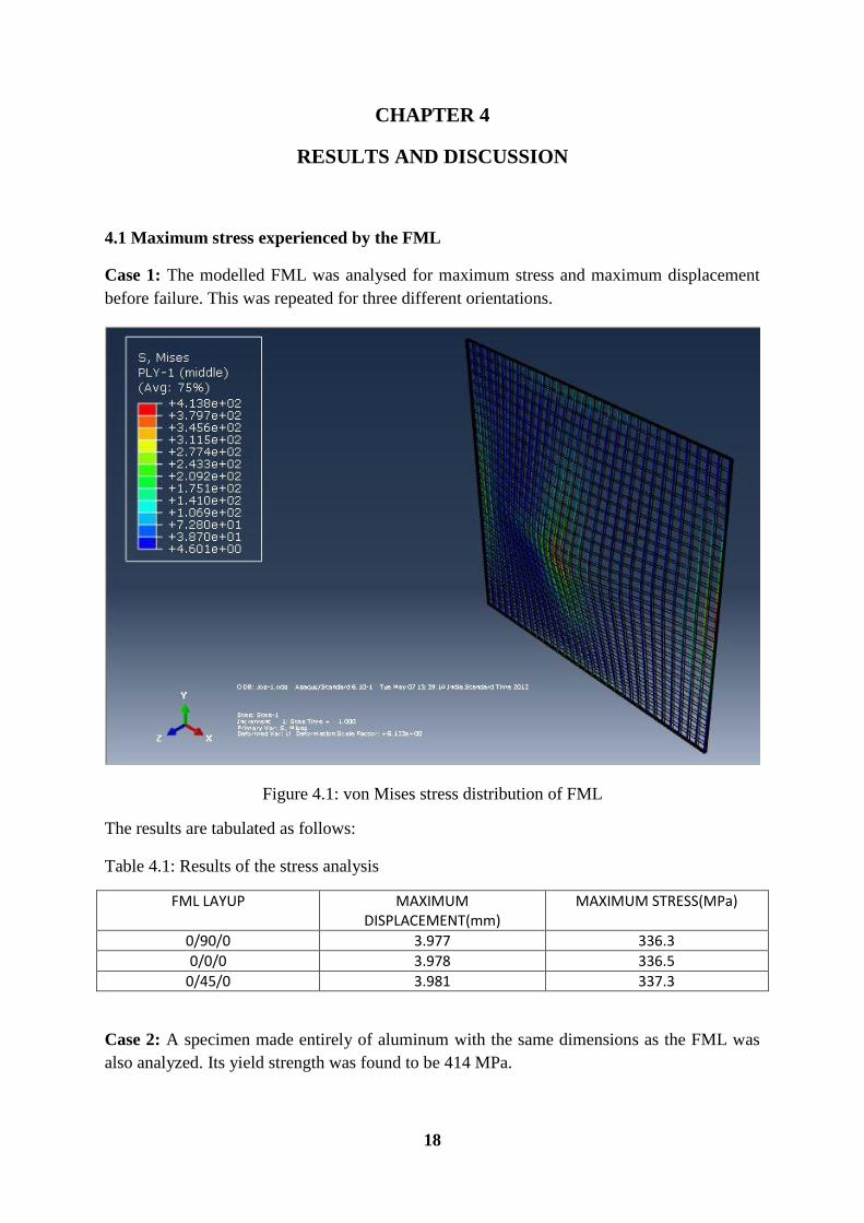
4.1 Maximum stress experienced by the FML
Case 1: The modelled FML was analysed for maximum stress and maximum displacement
before failure. This was repeated for three different orientations.
Figure 4.1: von Mises stress distribution of FML
The results are tabulated as follows:
Table 4.1: Results of the stress analysis
FML LAYUP MAXIMUM DISPLACEMENT(mm)
MAXIMUM STRESS(MPa)
0/90/0 3.977 336.3
0/0/0 3.978 336.5
0/45/0 3.981 337.3
Case 2: A specimen made entirely of aluminum with the same dimensions as the FML was
also analyzed. Its yield strength was found to be 414 MPa.
19
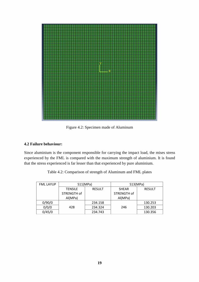
Figure 4.2: Specimen made of Aluminum
4.2 Failure behaviour:
Since aluminium is the component responsible for carrying the impact load, the mises stress
experienced by the FML is compared with the maximum strength of aluminium. It is found
that the stress experienced is far lesser than that experienced by pure aluminium.
Table 4.2: Comparison of strength of Aluminum and FML plates
FML LAYUP S11(MPa) S13(MPa)
TENSILE STRENGTH of
Al(MPa)
RESULT SHEAR STRENGTH of
Al(MPa)
RESULT
0/90/0 428
234.158 246
130.253
0/0/0 234.324 130.203
0/45/0 234.743 130.356
20
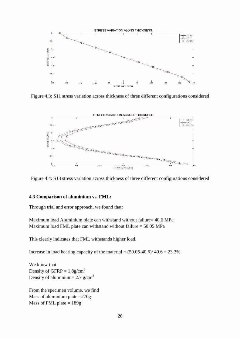
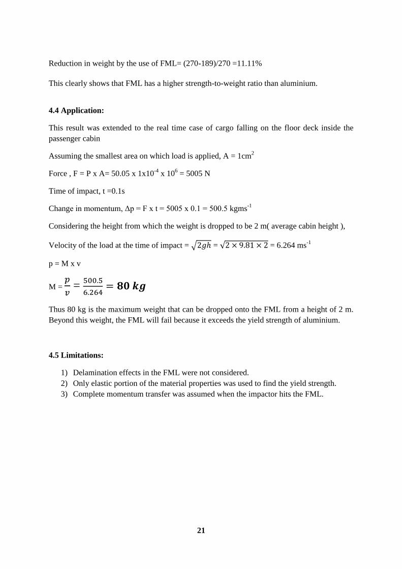
Figure 4.3: S11 stress variation across thickness of three different configurations considered
Figure 4.4: S13 stress variation across thickness of three different configurations considered
4.3 Comparison of aluminium vs. FML:
Through trial and error approach, we found that:
Maximum load Aluminium plate can withstand without failure= 40.6 MPa
Maximum load FML plate can withstand without failure = 50.05 MPa
This clearly indicates that FML withstands higher load.
Increase in load bearing capacity of the material = (50.05-40.6)/ 40.6 = 23.3%
We know that
Density of GFRP = 1.8g/cm3
Density of aluminium= 2.7 g/cm3
From the specimen volume, we find
Mass of aluminium plate= 270g
Mass of FML plate = 189g
21
Reduction in weight by the use of FML= (270-189)/270 =11.11%
This clearly shows that FML has a higher strength-to-weight ratio than aluminium.
4.4 Application:
This result was extended to the real time case of cargo falling on the floor deck inside the
passenger cabin
Assuming the smallest area on which load is applied, A = 1cm2
Force , F = P x A= 50.05 x 1x10-4
x 106 = 5005 N
Time of impact, t =0.1s
Change in momentum, Δp = F x t = 5005 x 0.1 = 500.5 kgms-1
Considering the height from which the weight is dropped to be 2 m( average cabin height ),
Velocity of the load at the time of impact = √ = √ = 6.264 ms-1
p = M x v
M =
=
Thus 80 kg is the maximum weight that can be dropped onto the FML from a height of 2 m.
Beyond this weight, the FML will fail because it exceeds the yield strength of aluminium.
4.5 Limitations:
1) Delamination effects in the FML were not considered.
2) Only elastic portion of the material properties was used to find the yield strength.
3) Complete momentum transfer was assumed when the impactor hits the FML.
22
CHAPTER 5
CONCLUSION
A study was done on the low velocity impact behaviour of Fibre Metal Laminates. A simple
layup of Al/GFRP/Al was considered and modelled in ABAQUS. The maximum stress
experienced by the FML was compared against the yield strength of the constituent materials
to find the maximum impact load that the FML can sustain without failure.
After a thorough study of the current research developments in this field, it was decided to go
for the numerical analysis approach due to the limitations of a bachelors’ level project.
The approach of ABAQUS analysis used was validated by the use of theoretical comparison.
Then the FML was modelled in ABAQUS and stress variation across the thickness of the
plate was plotted. It was observed to be behaving like a typical elastic material.
From this, using the failure criteria condition, the maximum stress that the FML can take
without failure was found. This was repeated for three different configurations/ orientations
viz. 0/0/0, 0/45/0, 0/90/0. It was found that the orientation of the fibres of GFRP did not have
a marked significance in the maximum stress that can be applied.
The maximum load that can be taken by the aluminium in the FML before failure was found
to be 50.05MPa and from this, the maximum weight of a projectile that can be dropped onto
the FML was found. It was seen that a weight of 80 kg can be dropped onto the FML from a
height of 2 m without any significant damage to itself.
This height of 2 m is the average height from the cabin floor to the overhead stowage bins in
an aircraft. However the maximum weight of carry-on baggage allowed internationally is
always equal to or less than 10 kg per person, indicating the use of a high factor of safety.
viii
REFERENCES
1) Tomblin J., Overview of Composite Material Trends in Aviation Manufacturing, National
Institute of Aviation Research, Wichita State University
2) Impact behaviour of Fiber Metal Laminates; Impact and dent damage Resistance, Delft
University of Technology, www.tudelft.nl
3) Aluminum 2024, Wikipedia-the free encyclopedia
4) F.D. Morinière, R.C. Alderliesten, R. Benedictus, Studies on energy distribution in GLARE
and 2024-T3 Aluminum during low velocity impact, 28th
International Congress of
aeronautical sciences , Delft University of Technology, 2012
5) Bieniaś J., Jakubczak P., Low Velocity Impact Resistance Of Aluminum/Carbon-Epoxy
Fiber Metal Laminates, Polish Society of Composite Materials , 12: 3 (2012) page:193-197,
Poland
6) Dr.Deo R.B.Dr.Starnes Jr.,H.J.,Holzwarth R.C.,Low-Cost Composite Materials and
Structures for Aircraft Applications,RTO AVT Specialists’ Meeting on “Low Cost
Composite Structures”, 7-11 May 2001,Norway
7) Peter Linde, Jürgen Pleitner, Henk de Boer, Clarice Carmone, Modelling and Simulation of
Fibre Metal Laminates,ABAQUS Users’ Conference pg.421, 2004
8) Prof. Jenn-Ming Yang,Damage Tolerance and Durability of Fiber-Metal Laminates for
Aircraft Structures,The Joint Advanced Materials and Structures Center of Excellence,USA
9) J.Laliberté, P.V.Straznicky, & C.Poon,Numerical Modelling Of Low Velocity Impact
Damage In Fibre-Metal-Laminates, International Congress Of Aeronautical
Sciences,2002,Canada
10) Alves M., Chaves C.E., Birch R.S., Impact On Aircraft
11) Shengqing Zhu, Gin Boay Chai, Low-velocity impact response of fibre–metal laminates –
Experimental and finite element analysis, School of Mechanical & Aerospace Engineering,
Division of Aerospace Engineering, Nanyang Technological University, Singapore
12) Edson Cocchieri Botelho,Almeida,SilvaLuiz,Cláudio Pardini,Mirabel Cerqueira Re
zende, A review on the development and properties of continuous
ix
fiber/epoxy/aluminum hybrid composites for aircraft structures, Materials
Research,Print version ISSN 1516-1439,vol.9 no.3, São Carlos July/Sept. 2006
13) Gautam S. Chandekar, Bhushan S. Thatte, and Ajit D. Kelkar, “On the Behavior of
Fiberglass Epoxy Composites under Low Velocity Impact Loading,” Advances in
Mechanical Engineering, vol. 2010, Article ID 621406, 11 pages, 2010.
doi:10.1155/2010/621406
x
APPENDIX
CALCULATION FOR MAXIMUM DEFLECTION OF ALUMINIUM RECTANGULAR
PLATE WITH FIXED EDGES UNDER UNIT LOAD AT THE CENTER :
α = 0.0056
Load, P = 1N
Side of plate, a = 100 mm
Young’s modulus, E =70 GPa
Poisson’s ratio, = 0.3
Flexural rigidity,
= 6410.256 Nmm
Deflection,
w= 8.736E-03 mm
Result from abaqus, w= 8.748E-03 mm
Analytical Numerical Error
Deflection 8.736E-03 8.748E-03 0.14%
MAXIMUM DEFLECTION OF ALUMINIUM RECTANGULAR PLATE WITH FIXED
EDGES UNDER UNIFORMLY DISTRIBUTED LOAD OF 10PA :
Load ,q =10Pa
a=100mm
Flexural rigidity,
= 6410.256 Nmm
= 1.965E02 mm
xi
Analytical Numerical Error
Deflection 1.965E02 1.975E02 0.5%
MAXIMUM DEFLECTION OF GFRP RECTANGULAR PLATE WITH FIXED EDGES
UNDER UNIFORMLY DISTRIBUTED LOAD OF 10PA :
Load, = 10Pa
Side , a = 100mm
Aspect ratio , c = b/a = 1
= 0.24
Flexural rigidity,
= 2122.24 Nmm ;
= 1945.388Nmm
D1 = = 466.893 Nmm
Dxy = D(1- = 739.247 Nmm
Effective torsional rigidity, H=D1+2Dxy =1945.388 Nmm
Equivalent rigidity, = 7 = 36254.948 Nmm
Deflection,
= 6.599E02mm
Analytical Numerical Error
Deflection 6.599E02 6.921E02 4.6%
Related Documents