Leif Lindau, Barbara Goldschmidt MATERIALS TECHNOLOGY 1053 Low temperature corrosion in bark fuelled, small boilers

Welcome message from author
This document is posted to help you gain knowledge. Please leave a comment to let me know what you think about it! Share it to your friends and learn new things together.
Transcript

t
3
Low temperature corrosion in bark fuelled, small boilers
MATERIALS TECHNOLOGY 105
Leif Lindau, Barbara Goldschmid


Low temperature corrosion in bark fuelled, small boilers
Leif Lindau, Barbara Goldschmidt
M9-835
VÄRMEFORSK Service AB 101 53 STOCKHOLM · Tel 08-677 25 80
May 2008 (orig. June 2002) ISSN 1653-1248


VÄRMEFORSK
Abstract
Low temperature corrosion in biofuel fired plants was investigated. The investigations comprised plant inspections, analysis of deposits and probe tests. A plausible mechanism for this type of corrosion was identified. Corrosion probe tests, which were made, reproduced the plant experiences. The design criterion, to ensure that this type of corrosion is avoided in this type of plants, was established to be relative humidity <22% (calculated from the water content of the flue gas and the temperature of the feed water). Plants, which had earlier experienced corrosion, and where the water temperature has been increased, have become free from corrosion.
i

VÄRMEFORSK
ii

VÄRMEFORSK
Sammanfattning
Ett antal nyuppförda små (3-12 MW) biobränslepannor i Sverige och (åtminstone) i Österrike har drabbats av en snabb (mm/år) korrosion på lågtemperatursidan. Detta problem har undersökts till omfattning och karaktär genom kontakter med drabbade anläggningsägare, besiktningar och genom analys av påslag från korroderat område. Drabbade anläggningar har låga vattentemperaturer (<100 oC), och använder olika typer av svenska biobränslen: flis, bark, sågverksavfall och GROT. Funna resultat ger grund för en hypotes att korrosionen uppstår då en vattenfas stabiliserad av inlösta salter med hög löslighet finnes som del av påslagen. Härav följer det att för varje salt finnes en kritisk relativ fukthalt (beräknad från rökgasens fukthalt och kylytans temperatur på sätt som är praxis bland äldre ångtekniker) under vilken vattenfasen och därmed korrosionen försvinner. Några kritiska enkelsalter CaCl2 och ZnCl2 har identifierats, vilket ger ett teoretiskt baserat kriterium för korrosionsfrihet: att ”relativ fukthalt” ska vara <5% för ZnCl2 och <18% för CaCl2. Dessa siffror är en undre gräns. Ur de empiriska anläggningserfarenheterna, och baserat på uppgivna driftdata blir kriteriet mellan 25% och 30%. Korrosionsförsök har genomförts genom exponering av en luftkyld sond i rökgas från en 12 MW panna på Sävelundsverket i Alingsås. Materialförlusten vid olika temperaturer har mätts med profilometer. De höga korrosionshastigheterna har reproducerats i försöken för höga relativa fukthalter. Korrosionshastigheten var låg och ej mätbar (< 0,1 mm/år) för relativ fukthalt <22%. Arbetet visar (genom indirekt bevisföring) att korrosionsdrivande förening är ZnCl2 och att möjligen även Ca Cl2 är det. Det ur detta arbete härledda praktiska ingenjörskriteriet för utläggning av anläggningar av denna typ är att relativ fukthalt (beräknat med rökgasens vattenpartialtryck och matarvattnets temperatur) skall vara <22%.
iii

VÄRMEFORSK
iv

VÄRMEFORSK
Summary
A number of small (3-12 MW), new biofuel boiler plants in southern Sweden, and (at least) in Austria, have suffered a high (wastage of mm/yrs.) corrosion rate on the low temperature boiler side. This problem has been investigated with respect to its occurrence and its character by contacts with operators, by plant inspections, and by analysis of cold-side deposits. The plants affected have low feed water temperatures (< 100 oC). The plants fire most types of Swedish biofuel: chips, bark, hog fuel, and “GROT”(=twigs and tops). The results found give basis for a hypothesis that the corrosion results from the presence of an aqeous phase in the deposits, this phase being stabilized by dissolved salts having high solubility. It then follows that for each salt, there is a critical relative humidity (calculated from the flue gas water partial pressure and the cooling surface temperature as is common practice among boiler engineers) for both the presence of the aqeous phase and the corrosion. Some critical single salts, ZnCl2 and CaCl2 have been identified, and they give critical “relative humidities” of 5% and 18% respectively. These figures are a lower bound. The corresponding figure, derived from the practical experience and the reported plant operational data, is between 20 and 30%. Corrosion tests have been carried out by exposing an air-cooled probe in the flue gases at a 12 MW boiler at Sävelundsverket in Alingsås, and the material wastage at different temperatures has been measured with a profilometer. The high corrosion rates were reproduced in the tests for high relative humidities. The corrosion rate was small and not measurable (<0.1 mm/year) for relative humidity <22%. The work shows by means of indirect evidence that the corrosion critical components are ZnCl2 and possibly CaCl2 as well. The practical engineering design criterion derived from the work is that the relative humidity (calculated from the flue gas water partial pressure and the feed water temperature) in this type of plants should be less than 22%.
v

VÄRMEFORSK
vi

VÄRMEFORSK
Table of contents
1 INTRODUCTION .................................................................................................. 1 1.1 BACKGROUND ...................................................................................................... 1 1.2 DESCRIPTION OF THE PLANT TYPE............................................................................. 1 1.3 THE PROBLEM....................................................................................................... 2 1.4 PURPOSE OF THE PROJECT...................................................................................... 2
2 METHODS ........................................................................................................... 3 2.1 EXPERIENCES FROM EXISTING PLANTS ....................................................................... 3 2.2 TESTS WITH CORROSION PROBES ............................................................................. 3
3 RESULTS ............................................................................................................ 8 3.1 EXPERIENCES FROM EXISTING PLANTS ....................................................................... 8 3.2 RESULTS FROM THE CORROSION TESTS ................................................................... 14
4 DISCUSSION..................................................................................................... 19 4.1 HYPOTHESIS ...................................................................................................... 19 4.2 DISCUSSION OF THE CONDITIONS ON THE LAST HEAT SURFACES ................................... 19 4.3 THE DRH CONCEPT ............................................................................................. 21 4.4 PHASES IN DEPOSITS FROM THE INSPECTED PLANTS................................................... 26 4.5 RESULTS FROM THE TESTS WITH CORROSION PROBES................................................. 28
5 CONCLUSIONS ................................................................................................. 29
6 SUGGESTIONS FOR CONTINUED RESEARCH................................................... 30
7 REFERENCES ................................................................................................... 31
vii


VÄRMEFORSK
1 Introduction
1.1 Background
The background of the project is that a number of boilers in the 2-12 MW range, fired with bark and other biofuels, have suffered from low temperature corrosion at a considerable rate. The aim of the project reported here, was to solve the low temperature corrosion problem in this type of boilers. The project included interviews with plant owners, corrosion rate measurements by corrosion probes, as well as attempts to provide basic explanations to the phenomenon and elaboration of design criteria to prevent future problems.
1.2 Description of the plant type
All of the plants discussed in this report are of the type shown in the figure below (however, only the larger plants have electrofilters and condensers). The plants consist of a pre-furnace with moving grate followed by one or two fire tube boilers with vertical gas flow in three or four channels. The diameter of the fire tubes on the outlet side is 75 mm or less. In larger plants, flue gas is recirculated to the pre-oven. Today, this type of plant is built in sizes up to ca 12 MW. The boilers are stopped and manually cleaned from soot when required, which may be every third to sixth month. The plants are operated unattended during most of the time, and have running times of 9-11 months/year.
Fjv
Rökgas-kondensor
Elfilter
Skorsten
Rökgas-fläkt
Bränsle-inmatning
Cyklon
Eldstad
Panna
Luft-fläkt
Figure 1. The plant type
Figure 2. The area where the fire tubes are welded to the tube plate (Rörvik)
1

VÄRMEFORSK The plants are fired with chips, bark, hog fuel, and “GROT”(=twigs and tops) with moisture contents between 35% and 55%. In plants where low NOx emissions are required, low O2 contents are aimed for (2% in wet gas). In smaller plants the O2 content is ca 6%. At full load the flue gas temperature is 170-190°C and at minimum load ca 130°C. There are plants both with and without heat exchangers between boiler water and the district heating net.
1.3 The problem
The problem is corrosion in the fire tubes, especially in the lower part near the tube plate. A high rate of loss of material, some mm/year, is typical of the corrosion. Since there is no remaining corrosion product, the corrosion is not easily observed by superficial inspection. It can, however, be measured by dimension control of the diameter. By electromagnetic (eddy current) measurements of electrical conductivity the thickness of the boiler tube can be mapped, except for the area nearest to the tube plate. The phenomenon caused breakdown with boiler leakage e.g. at the Sydkraft plant Sävelundsverket in Alingsås during the season 2000-2001. Informal contacts with several plant owners in Sweden, as well as with suppliers, showed that the phenomenon was known at some plants of this type, and completely unknown at others. No technical explanation was known, and no solution to the problem was known either.
1.4 Purpose of the project
The purpose of the project is to − elucidate the extent of the problem − gather and evaluate technical information from affected plants − acquire knowledge and understanding of the corrosion mechanism − investigate the corrosion rate and corrosion area experimentally − suggest constructive measures against the corrosion, based on obtained experience
2

VÄRMEFORSK
2 Methods
First an investigation was made on corrosion problems in plants of the type in question. Then tests with corrosion probes were made in one of the plants.
2.1 Experiences from existing plants
The first step was to gather experiences from existing plants for diagnostic purposes. This was made through telephone interviews with about 10 plant owners in southern Sweden, where experience from this type of corrosion together with fuel data and other relevant operational experience was in demand. This was followed by visits and inspections at some plants, and chemical analysis of deposits from plants with corrosion problems.
2.2 Tests with corrosion probes
The tests with corrosion probes were made at Sävelundsverket in Alingsås, with kind assistance by the operational staff. Two tests with air cooled probes were made, during the operational season 2001-2002. The first test lasted for 4 weeks and the second for 6 weeks. The probes were placed in the flue gas path in the biofuel fired 12 MW boiler, between the cyclone and the electrofilter. The boiler was in operation during the whole period, with the exception of one day’s standstill at the end of the second test period.
2.2.1 Construction and manufacturing of probes
The probes were manufactured from cold-drawn precision carbon steel pipe (DIN 2391, St. 35). External diameter 10 mm, wall thickness 1.0 mm, pipe length 70 cm. A pipe length of 50 cm had been calculated to give a suitable temperature gradient between 70 and 110°C, with a cooling air flow of 10 m/s. The cooling air flow was adapted to the capacity of the plant’s instrument air compressor. To the active pipe length of 50 cm an additional 17 cm length was added to compensate for the wall thickness of the flue gas duct and the distance to the probe’s attachment to a connection piece on an inspection opening, plus 3 cm for holding fixture and cooling air connection on the outside. Total length: 70 cm. The probe temperature was measured in 3 places, with self-adhesive thermocouples. The thermocouple in the middle was used for both temperature measurement and regulation of the cooling air flow. The cooling air flow was controlled, by means of a control valve, by a regulator with the signal from the middle thermocouple as setpoint value. The temperatures and the position of the control valve were registered continuously by a data logger.
3

VÄRMEFORSK 2.2.2 Installation and commissioning
The probes were installed in a horizontal bend in the flue gas duct, between cyclone and electrofilter.
Figure 3. Placing of the corrosion probe in the flue gas duct (kylluft = cooling air, rökgas = flue
gas)
Before the tests, the temperature variations of the flue gas were registered with a separate (uncooled) probe. The temperature inside the flue gas duct varied from 140°C at low load to 180°C at maximum load. The outer 25 cm of the probe had constant temperature, the next 10 cm had a somewhat decreasing temperature, and the next 15 cm a strongly decreasing temperature down to 90°C and lower near the wall of the flue gas duct. The 17 cm closest to the probe’s attachment had rather constant temperature. After the mapping of the temperature profile in the flue gas duct, the cooling of the probe was tested at varying boiler load. With maximum cooling at full boiler load, the probe had a temperature between 130° at the inner part of the duct, and 60-70°C near the duct wall. Please note that the probes, from now on, are marked as followed: The tip of the probe in the inner part of the duct is marked 0 cm. From here the distance is measured towards the wall of the flue gas duct. The wall is at 50 cm, and the place of attachment at 67 cm. Since the variation in flue gas temperature is not constant over the cross-section of the flue gas channel (less variation at the walls), the thermocouple placed in the middle of the probe served as incoming signal for the regulator of the cooling air flow. Thermocouples were placed at 11 cm distance in the temperature range from 110°C down to 70-75°C. The air flow was controlled in such a way that the thermocouple in the middle always had a temperature of 103°C. During the corrosion test periods, the thermocouples were placed at 25, 36 and 47 cm, fastened with Teflon tape.
4

VÄRMEFORSK In order to have uncorroded probe areas as a reference at the end of the test periods, the probes were also masked with silicone in four places, at 20, 30, 41 and 51 cm. In the figure below the probe is seen, together with thermocouples, masking, and holder for the attachment in the inspection opening of the flue gas duct.
Figure 4. Corrosion probe before installation
After the mapping of the temperature profile in the flue gas duct, the probe was installed in the flue gas duct and the cooling air flow was started.
Figure 5. Installed corrosion probe
2.2.3 Corrosion tests
Two tests were made. The first probe was placed in the flue gas duct during 4 weeks in the autumn of 2001, and the second probe during 6 weeks in the winter of 2001-2002. Below a recording from the data logger is seen. The recording is for both test periods.
5
VÄRMEFORSK
0
10
20
30
40
50
60
70
80
90
100
110
120
09-no
v
16-no
v
23-no
v
30-no
v
07-de
c
14-de
c
21-de
c
28-de
c04
-jan
11-ja
n
Tem
pera
tur C
Prov 1 Prov 2
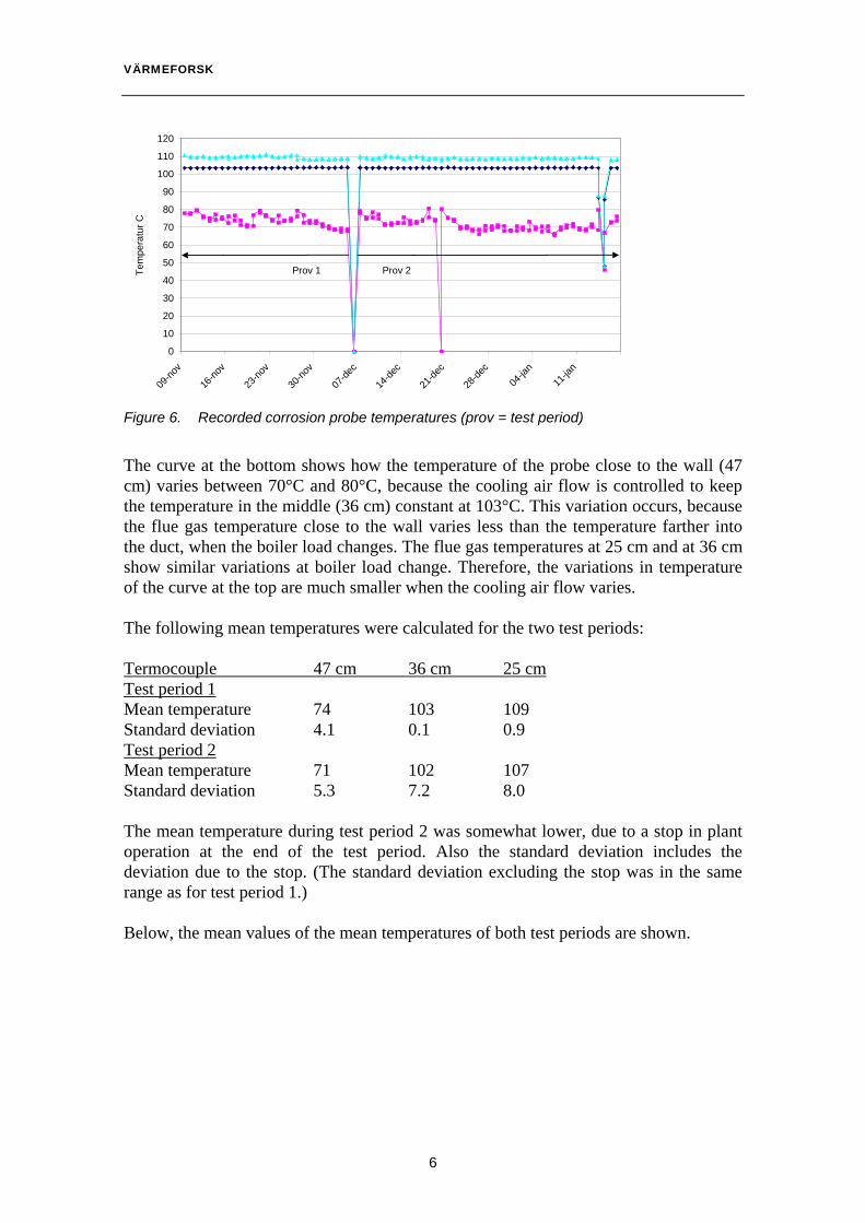
Figure 6. Recorded corrosion probe temperatures (prov = test period)
The curve at the bottom shows how the temperature of the probe close to the wall (47 cm) varies between 70°C and 80°C, because the cooling air flow is controlled to keep the temperature in the middle (36 cm) constant at 103°C. This variation occurs, because the flue gas temperature close to the wall varies less than the temperature farther into the duct, when the boiler load changes. The flue gas temperatures at 25 cm and at 36 cm show similar variations at boiler load change. Therefore, the variations in temperature of the curve at the top are much smaller when the cooling air flow varies. The following mean temperatures were calculated for the two test periods: Termocouple 47 cm 36 cm 25 cm Test period 1 Mean temperature 74 103 109 Standard deviation 4.1 0.1 0.9 Test period 2 Mean temperature 71 102 107 Standard deviation 5.3 7.2 8.0 The mean temperature during test period 2 was somewhat lower, due to a stop in plant operation at the end of the test period. Also the standard deviation includes the deviation due to the stop. (The standard deviation excluding the stop was in the same range as for test period 1.) Below, the mean values of the mean temperatures of both test periods are shown.
6

VÄRMEFORSK
7
0
10
20
30
40
50
60
70
80
90
100
110
120
01020304050cm
Tem
pera
tur C
Figure 7. Temperature gradient of the corrosion probes

VÄRMEFORSK
3 Results
Results from plant inspections are reported in 3.1. Results from corrosion tests are reported in 3.2.
3.1 Experiences from existing plants
Sävelundsverket, Alingsås Sävelundsverket in Alingsås is owned by Sydkraft Värme Syd, and has two lines with furnace and boiler, at 6 and 12 MW. The plant was taken into operation in 1998. The lines consist of furnace, cylindrical boiler with one channel upwards and one downwards, multicyclone, electrofilter and flue gas condenser (the latter is common to both lines). The flue gas temperature is 170°C at full load and 120°C at low load, and the O2 content is 2-2.5% (in wet gas). The temperature of incoming water to the boiler is 80-100°C. After ca two years of operation (in the autumn of 2000), the loss of material of the tubes in the cold end was measured to be up to ca 2 mm for several of the fire tubes. This can easily be measured, using a slide caliper rule, in the area where the tubes are connected to the tube plate. The loss of material differs between the tubes, but adjacent tubes have similar data. Some tubes started leaking during the season 2000-2001. The material appears to have been worn away evenly, and no corrosion product remains. During operation at low load it was noticed, that sometimes ash was coloured red from iron oxide. The boiler has now been rebuilt with increased water temperature, to minimise corrosion (heat exchangers have been installed between boiler water and district heating water). The fuel mix (ratios based on heating values) during the high load season 2000-2001 consisted of: Ratio Mean moisture content Bark 19% 65% Cleaning bark 11% 65% Chips 20% 53% Hog fuel 25% 21% Briquettes 25% low Yearly mean value 53% Cleaning bark comes from loading and handling of wood, and is collected here and there at sawmills. Based on the yearly mean value of the fuel moisture content, and O2 as above, the mean moisture content of the flue gas becomes 32%. During the winter of
8

VÄRMEFORSK 2000-2001, in November-March, composite samples of all delivered fuels were taken. The analyses have been put at the author’s disposal by Sydkraft, Thomas Karlsson. Olofström The 4 MW plant is owned by the municipality of Olofström, and was taken into operation in 1998. The furnace and oven are of the Järnforsen “Integral IV” type with furnace and oven built together as one unit. The last channel has upwards gas flow. The flue gas temperature is 170-200°C, and the O2 content 5% in wet gas (higher at low load). Return water is led to the lower part of the boiler by a baffle plate directed downwards. Originally the return water temperature was 85°C. Boiler water is heat exchanged with district heating water. The fuel is GROT with minor amounts of chips, and the fuel moisture content is 35-55%. This results in a moisture content of 23-33% in the flue gas. Cl contents of 0.02% and S contents of 0.03% have been analyzed in the fuel. After one and a half years of operation the boiler tubes were exchanged, due to corrosion in the mm range, in the lower part where the water temperature is at its lowest. After the exchange of tubes, the return temperature was increased to 100°C, starting in the autumn of 2000. It seams that this has slowed down the corrosion rate. During the inspection 2002-06-25, some traces of fresh corrosion were noticed under the ash deposits before soot removal. Rörvik The 6 MW plant delivers heat to the wood drier at Rörvik Timber in Rörvik. The plant is operated continuously during the year, with a four weeks summer stop. The load is ca 3 MW. The plant consists of a pre-furnace (KMW) and a separate cylindrical boiler (Veå). The plant was taken into operation during the season 1998-1999. The fuel has been cleaning bark from the sawmill, which has been mixed with 50% ordinary bark during the latest season. The fuel moisture content is 45-50%. The O2 content is ca 7%. This results in a moisture content of 27-30% in the flue gas. The flue gas temperature (at 3 MW) is 130°C. The return water temperature to the boiler was 100°C during the first two seasons, but was increased to 107°C during the autumn of 2000. Based on the experiences from Alingsås, there were concerns that also this plant might corrode. However, no tube breakage has occurred, which suggests that the corrosion rate is not high. Recent electromagnetic (eddy current) measurements of electrical conductivity show, that the material thickness has not changed significantly during three operational seasons. Thus, this plant does not corrode in the low temperature area.
9

VÄRMEFORSK Some other, similar plants Besides the visited plants, some other owners of similar plants in southern Sweden have been interviewed concerning their experience of corrosion in the boiler. 1. Harven Plant owner: Skara Energi AB Contact: Bengt Rask, +46 798-180583 Output: 13 MW Building year: 1999 Fuel: Bark, hog fuel, chips Flue gas temperature: 140°C O2: 1-2% Return water temperature: 85°C at first, then raised to 105°C Corrosion: Earlier “red ash” was observed, as a sign
of rapid corrosion, this symptom disappeared after temperature increase.
2. Axeln 1 Plant owner: Alvesta Energiverk Contact: Hans Kristoffersson, +46 70-314 9991 Output: 6 MW Building year: 1995 Fuel: Bark, hog fuel, chips Flue gas temperature: 150°C O2: 5.6% Return water temperature: 100°C Corrosion: None 3. Moheda Plant owner: Alvesta Energiverk Contact: Hans Kristoffersson, +46 70-314 9991 Output: 8 MW Building year: 2000 Fuel: Bark, hog fuel, chips Flue gas temperature: 150°C O2: 3% Return water temperature: 100°C Corrosion: None 4. Mården 2 Plant owner: Höörs Energiverk Contact: Sven-Erik Jönsson, +46 413-28490 Output: 2.5 MW Building year: 1997 Fuel: Chips Flue gas temperature: 150°C O2: 5%
10

VÄRMEFORSK Return water temperature: 100-105°C Corrosion: None 5. Vittskövle Sågverk Plant owner: Vittskövle Sågverk Contact: Greger Jansson, +46 70 8125613 Output: 4,5 MW Building year: 1992 Fuel: Bark, chips Flue gas temperature: 150-180°C O2: Uncertain information Return water temperature: 80-85°C Corrosion: Leaking tubes and loss of material in tube
plate. Other experiences During the nineties, Sweden financed the conversion from oil to local biofuels of a number of heat plants in the Baltic States. These are fired with fuels similar to fuels used in Sweden, but differ from the Swedish plants by being water tube boilers designed for higher temperatures (e.g. due to sulphuric acid from oil firing). According to received information, the problem is unknown in the Baltic States (information from Dr Nerjius Pedisius, Lithuanian Energy Institute, Kaunas). Boilers in the board industry, which are also fired with moist bark, are also designed for higher return water temperatures. In Austria there are biofuel fired district heating plants, up to some MW, similar to those in Sweden. Contact with two companies, “Nahwärme Schuster” in Graz and “KWI” in St Pölten (www.kwi.at), showed that similar low temperature corrosion is a big problem in Austria, and 20% of all small plants are said to be affected (W Hofbauer, KWI). The water temperatures to the boilers are very low. KWI is preparing an EU project on this. Summary of empiric experience form investigated plants Plant Water temp, °C O2 , % in wet gas corrosion Alingsås 80-100 2 yes Olofström 100 5 no Olofström < 100 5 yes Rörvik 107 7 no Harven 105 2 no Axeln 1 100 6 no Moheda 100 3 no Mården 100 5 no Vittskövle 80-85 ? yes
11

VÄRMEFORSK The practical experience from these plants with fire tube boilers with manual soot removal, which are fired with various biofuels existing in southern Sweden, thus, is that with water temperatures to the boiler in the range 85-100°C there is a high risk of rapid corrosion (mm/year) in areas where the water is at its coldest (Alingsås, Olofström at earlier conditions). This is mainly when the main fuel is bark or GROT. With water temperatures above 100°C and 5% O2 (Olofström after reconstruction) or 105°C and 1.5% O2 (Harven) the problem seems to diminish or disappear. Expressed in terms of relative humidity in the flue gas at the coldest heat surface, RH above 30% results in rapid corrosion. The size of the corrosion (amounting to mm/year) at low temperature, and the appearance of the corrosion, suggests that this is a type of condensation corrosion. The plants have long hours of operation and few stops every year, which is why the corrosion mechanism is probably active during long operation periods and not restricted to e g start and stop. The problem appears not to be much known outside the circle of operational staff, although the technology with pre-oven and fire tube boilers is well-established. The problem exists at least also in Austria.
3.1.1 Fuel analysis
Fuel analyses have been obtained from Alingsås (several samples) and from Rörvik. As the discussion is concentrated on the elements Ca, Zn, S and Cl, only the corresponding data are reported here. The values are given as %, in dry matter. 1. Alingsås, composite samples from winter season 2000-2001: Bark Cleaning bark Dry chips Hog fuel Saw dust CaO 1.4 1.2 0.11 0.11 0.11 ZnO 0.024 0.016 0.0017 0.0012 0.0020 S 0.03 0.045 0.01 0.01 0.01 Cl 0.039 0.036 0.006 0.008 0.032 Ash content 3.8 3.9 0.30 0.40 0.44 2. Rörvik: Bark Cleaning bark CaO 1.1 1.19 ZnO 0.014 0.0085 S 0.032 0.035 Cl 0.02 0.04 Ash content 2.7 5.9 Thus, bark and cleaning bark from various plants in the same region are rather similar in these aspects. The higher ash content of the cleaning bark occurs together with higher Si and Al content.
12

VÄRMEFORSK 3.1.2 Analysis of deposits in the corrosion area
Samples of deposits on the heat surfaces were taken from the area where corrosion occurs (which coincides with the area where the boiler water can be predicted to be at its coldest, in the lower part of the boiler). Samples were taken by brushing off deposit using a bottle brush, and letting it fall down into a bottle. Sample no 1 from Alingsås was taken from tubes which were removed from the boiler due to breakthrough corrosion, and no 2 directly from the boiler. The samples were analyzed by ICP (Inductively Coupled Plasma Spectroscopy) when enough sample (5 g) was available (Olofström och Rörvik) and by SEM-EDX (Scanning Electron Microscopy) when less sample was available (Alingsås). As the discussion is concentrated on the elements Ca, Zn, S and Cl, only the corresponding data are reported here. Alingsås 1 Alingsås 2 Olofström Rörvik CaO 31.6 8.8 21.4 9.9 ZnO 0.6 0.7 4.4 5.2 S 7.6 3.2 6.6 9.0 Cl 3.0 1.3 6.6 2.7 S/CaO 0.24 0.36 0.31 0.27 Cl/CaO 0.09 0.15 0.31 0.27 The values of the deposits can be compared to values obtained when the fuel analyses (mean values of various fuels) are converted to incinerated samples in the tables below. For the Alingsås fuels: Bark Cleaning bark Dry chips Hog fuel Saw dust CaO, % 36 15.8 37.2 26.2 23.8 ZnO, %, 0.62 0.21 0.57 0.30 0.45 S, % 0.77 0.59 3.3 2.5 2.3 Cl , % 0.95 0.47 2.0 2.0 7.3 S/CaO 0.02 0.03 0.09 0.1 0.1 Cl/CaO 0.03 0.03 0.05 0.08 0.3 For the Rörvik fuels: Bark Cleaning bark CaO, % 41 20 ZnO 0.54 0.14 S 1.2 0.59 Cl 0.75 0.68 S/CaO 0.03 0.029 Cl/CaO 0.02 0.03 Thus, S and Cl is enriched relatively to CaO in the deposits, in comparison to the net fuel composition
13

VÄRMEFORSK Further, X-ray diffraction analysis (XRD) was made on crystalline phases of scraped-off material. The method allows detection of crystalline phases, which are present in amounts corresponding to some %. The detected phases were: Alingsås 1: Hematite, quartz, hydrated calcium sulphate (gypsum = CaSO4.2H2O) Alingsås 2: Hematite, calcium sulphate (anhydrite = CaSO4) Rörvik: Hematite, aphthialite (K3Na(SO4)2), anhydrite (CaSO4).
3.2 Results from the corrosion tests
After both tests, the probes were taken out for measurement of loss of material and analysis of dust deposits. The probes then had a thin layer of greyish white dust deposit (<1 mm). The deposit occurred mainly on the front side of the probes, towards incoming flue gas.
Figure 8. Corrosion probe, with dust covered front side
3.2.1 Loss of material
The rusty probes were brushed clean from dust deposit. Dust samples from different temperature areas were sent away for analysis. See below. Both probes had a thick, coarse, rough, reddish brown rust layer in the temperature range close to and below the water dew point, which was calculated to 65-67°C. The thickness of the rust layer (of the probe from test period 1) was analyzed by electron microscope in a cross-section at ca 60°C. The thickness of the rust layer on the bottom side was ca 10-100 µm, and on the top side ca 100-500 µm. Below, a picture of the corrosion layer on the top side of the probe is shown.
14

VÄRMEFORSK
Figure 9. Corrosion in the area below dew point temperature (plastinbakning = plastic mould, korrosionsskikt = corrosion layer, opåverkad yta = unaffected area, grader = degrees)
In the area from the place of attachment (below the dew point) and all the way to the thermocouple in the middle at 36 cm (103°C), corrosion was seen distinctly. The rust was coherent all the way to the masking at 41 cm (100°C). From there, and to the thermocouple in the middle (103°C), a gradual transition to pitting was seen, especially on the top and bottom sides of the probes. Farther out, towards the tip of the probe, no clear corrosion was seen, only possible traces of surface rust. The probes were blasted with glass beads, to remove the corrosion layer. The blasted probes were then analyzed with a profilometer. The profilometer measures the depth of cavities in the surface of the probe, with the unaffected areas below masked areas as a reference 0 level.
Figure 10. Profilometer
The blasting resulted in a surface coarseness of ca 5-10 µm. The rust attacks were seen as pitting (<1 mm diameter) or as corrosion over larger areas. The probes were measured by profilometer in the temperature range 90-110°C. (The 70-90°C area was unaffected, since it was protected by the Teflon tape, which was used to
15
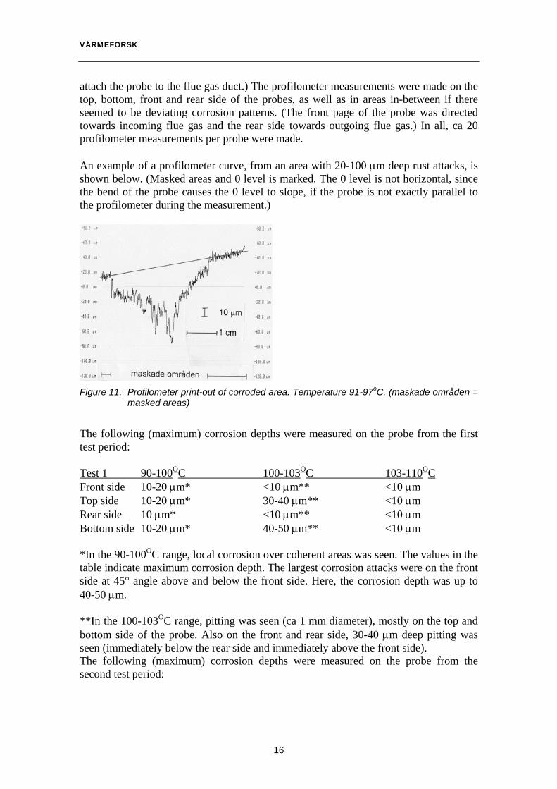
VÄRMEFORSK attach the probe to the flue gas duct.) The profilometer measurements were made on the top, bottom, front and rear side of the probes, as well as in areas in-between if there seemed to be deviating corrosion patterns. (The front page of the probe was directed towards incoming flue gas and the rear side towards outgoing flue gas.) In all, ca 20 profilometer measurements per probe were made. An example of a profilometer curve, from an area with 20-100 µm deep rust attacks, is shown below. (Masked areas and 0 level is marked. The 0 level is not horizontal, since the bend of the probe causes the 0 level to slope, if the probe is not exactly parallel to the profilometer during the measurement.)
Figure 11. Profilometer print-out of corroded area. Temperature 91-97oC. (maskade områden = masked areas)
The following (maximum) corrosion depths were measured on the probe from the first test period: Test 1 90-100OC 100-103OC 103-110OC Front side 10-20 µm* <10 µm** <10 µm Top side 10-20 µm* 30-40 µm** <10 µm Rear side 10 µm* <10 µm** <10 µm Bottom side 10-20 µm* 40-50 µm** <10 µm *In the 90-100OC range, local corrosion over coherent areas was seen. The values in the table indicate maximum corrosion depth. The largest corrosion attacks were on the front side at 45° angle above and below the front side. Here, the corrosion depth was up to 40-50 µm. **In the 100-103OC range, pitting was seen (ca 1 mm diameter), mostly on the top and bottom side of the probe. Also on the front and rear side, 30-40 µm deep pitting was seen (immediately below the rear side and immediately above the front side). The following (maximum) corrosion depths were measured on the probe from the second test period:
16
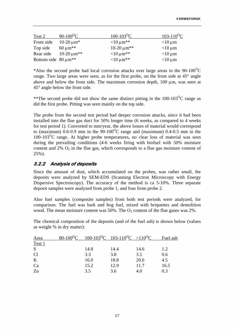
VÄRMEFORSK Test 2 90-100OC 100-103OC 103-110OC Front side 10-20 µm* <10 µm** <10 µm Top side 60 µm** 10-20 µm** <10 µm Rear side 10-20 µm** <10 µm** <10 µm Bottom side 80 µm** <10 µm** <10 µm *Also the second probe had local corrosion attacks over large areas in the 90-100OC range. Two large areas were seen, as for the first probe, on the front side at 45° angle above and below the front side. The maximum corrosion depth, 100 µm, was seen at 45° angle below the front side. **The second probe did not show the same distinct pitting in the 100-103OC range as did the first probe. Pitting was seen mainly on the top side. The probe from the second test period had deeper corrosion attacks, since it had been installed into the flue gas duct for 50% longer time (6 weeks, as compared to 4 weeks for test period 1). Converted to mm/year, the above losses of material would correspond to (maximum) 0.6-0.9 mm in the 90-100OC range and (maximum) 0.4-0.5 mm in the 100-103OC range. At higher probe temperatures, no clear loss of material was seen during the prevailing conditions (4-6 weeks firing with biofuel with 50% moisture content and 2% O2 in the flue gas, which corresponds to a flue gas moisture content of 25%).
3.2.2 Analysis of deposits
Since the amount of dust, which accumulated on the probes, was rather small, the deposits were analyzed by SEM-EDS (Scanning Electron Microscopy with Energy Dispersive Spectroscopy). The accuracy of the method is ca 5-10%. Three separate deposit samples were analyzed from probe 1, and four from probe 2. Also fuel samples (composite samples) from both test periods were analyzed, for comparison. The fuel was bark and hog fuel, mixed with briquettes and demolition wood. The mean moisture content was 50%. The O2 content of the flue gases was 2%. The chemical composition of the deposits (and of the fuel ash) is shown below (values as weight % in dry matter): Area 80-100OC 100-103OC 103-110OC >110OC Fuel ash Test 1 S 14.8 14.4 14.6 1.2 Cl 3.3 3.8 3.5 0.6 K 16.0 18.8 20.6 4.5 Ca 15.2 12.9 11.7 16.5 Zn 3.5 3.6 4.0 0.3
17
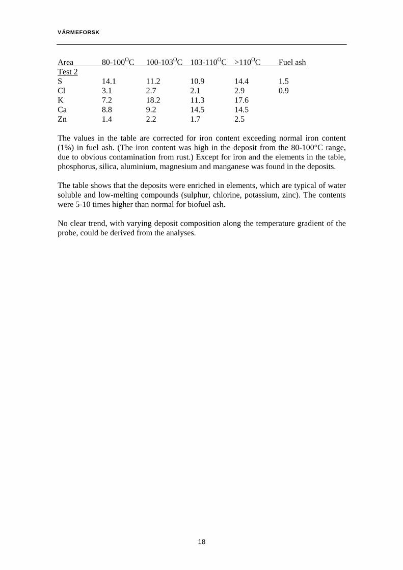
VÄRMEFORSK Area 80-100OC 100-103OC 103-110OC >110OC Fuel ash Test 2 S 14.1 11.2 10.9 14.4 1.5 Cl 3.1 2.7 2.1 2.9 0.9 K 7.2 18.2 11.3 17.6 Ca 8.8 9.2 14.5 14.5 Zn 1.4 2.2 1.7 2.5 The values in the table are corrected for iron content exceeding normal iron content (1%) in fuel ash. (The iron content was high in the deposit from the 80-100°C range, due to obvious contamination from rust.) Except for iron and the elements in the table, phosphorus, silica, aluminium, magnesium and manganese was found in the deposits. The table shows that the deposits were enriched in elements, which are typical of water soluble and low-melting compounds (sulphur, chlorine, potassium, zinc). The contents were 5-10 times higher than normal for biofuel ash. No clear trend, with varying deposit composition along the temperature gradient of the probe, could be derived from the analyses.
18
VÄRMEFORSK
4 Discussion
4.1 Hypothesis
Based on the empirical experience, which has been reported above, the hypothesis is that low return water temperature causes a corrosive water phase with high salt content to be stable on the coldest heat surfaces during normal operation. In such a stable water phase, acidic components from passing flue gas (HCl and SO2) will be dissolved, and lower the pH and render the deposits corrosive, at least if the water phase is present in sufficient amount. Intuitively, it seems obvious that the corrosion increases with increasing water phase ratio, e.g. since this results in a conductivity which increases rapidly with increasing liquid phase ratio in the deposit. The corrosion mechanism, according to the knowledge of the author, has not been described in connection with boilers earlier, although it is well known among practitioners that some hygroscopic salts are corrosive. Thus, the hypothesis here is that corrosive dust consists of a mixture of dust and a water phase. The corrosion stops, when the flue gas becomes so hot or dry, that the water phase decreases enough or totally disappears. A frequent explanation to condensation corrosion is precipitation of water at the water dew point, which is 55-65°C. This is not possible with normal water temperatures during operation, which is why this cannot explain this corrosion. Another frequent explanation is that the corrosion is caused by SO3. However, SO3 is practically totally absorbed by chlorides at temperatures <250°C, which also forms the base of the NaCl method for SO3 analysis [1]. Thus, this does not explain the corrosion in the temperature range in question.
4.2 Discussion of the conditions on the last heat surfaces
During operation, a selection of the fly ash is deposited on the heat surfaces. The composition of the deposit closest to the steel is given by the zero approximation of a mean composition of passing fly ash, the main components of which are
− inert material with SiO2 and Al2O3 and some alkali, which has fused to a glass phase with silica and aluminium oxide
− almost insoluble compounds of the calcium carbonate type − compounds of the calcium carbonate type, which are difficult to dissolve − soluble compounds, e g sodium and potassium salts − extremely soluble compounds, e g calcium and zinc chlorides This is a rough first approximation, since the selection of what remains in deposits on heat surfaces and duct walls from passing flue gas with fly ash may have a composition, which is considerably different form the composition of the passing fly ash. Let us assume that the boiler is stopped and later started up again without sootblowing, or at least that the sootblowing is not perfect so that some of this material remains on
19

VÄRMEFORSK the heat surface when the boiler is started up. During start-up, the boiler circulation is started at first and will have a temperature equal to the district heating return temperature of ca 45-50°C. Then the boiler is lit up with dry fuel, which has been put aside for this purpose, and when the fire is stable, ordinary wet fuel is added. Firing with wet wood fuel (15% moisture) gives a water dew point of ca 50-55°C, and therefore water condensation occurs during the whole start-up. This is also observed in practice. A 4 MW boiler has a water content of ca 20 m3, and when this is heated 10°C, 350 kg of water condenses. The condensed water will dissolve all extremely soluble, easily soluble and some soluble substances in the ash, which remains on the tubes, and become saturated with substances which are difficult to dissolve. Some of this solution will run down to the ash collector of the boiler together with the ashes’ content of inert material and almost insoluble substances, and some will remain on the tube surface. In addition, the material which remains on the tube surface (some water phase, some insoluble inert particles) will be compacted by capillary forces so that its strength is increased. If the flue gas contains HCl and SO2, this will be absorbed by the water phase and decrease its pH. This will drive out carbonate and bicarbonate from the water phase and increase the chloride content in the water phase and the sulphate content in the deposits. As the boiler water temperature is increased above the water dew point of the flue gas, due to the heat input, the condensed water film will start to dry. Dissolved material starts to precipitate out from the now supersaturated solution, which is enriched with chloride and depleted with e.g. carbonate in comparison to the original situation. In addition, the water partial pressure of the solution decreases with increasing ionic strength in the water phase, which delays the drying (see below). The most soluble components will precipitate as salts last of all, and therefore one can predict that the composition of the deposit on the tube surface will be changed by this mechanism, and the ashes’ chloride content will be changed from less soluble chlorides (e g KCl and NaCl) to the most soluble chlorides (e g CaCl2 and ZnCl2). As the solubility order is ZnCl2, CaCl2, MgCl2, available chloride will first be paired with Zn, then Ca, and then Mg, K, Na, etc. However, the amount of Zn is limited, and in some cases also the Zn content is lower than the chloride content, so that normally chloride is sufficient also for CaCl2. On the other hand, the amount of Ca is always much larger than the amount of chloride, so there is not sufficient chloride for less soluble salts. In this discussion the additional degree of freedom, which comes with soluble double salts (of the type (Zn, Na) Cl), has not been considered, which may require a modification of the prediction. In the first approximation, based on the discussion above about the effect of a normal start-up, which involves condensation of water on the heat exchange surface, the prediction is instead that
20
VÄRMEFORSK - during operation after a start-up, the material closest to the tube surface will be
covered by a dried film of particles where the chlorides in the ash exist as the most soluble salts
- the salt which rather certainly exists is ZnCl2 - if locally there is Cl2>Zn, then also CaCl2 will exist - when the available amount of Ca exceeds the amount of Cl2, no other chlorides will
exist in the dried film These conclusions are made with reservation for possible modifications with regard to the existence of double salts. During start-up, when the film is wet, rich in chloride and warm, lively corrosion will occur. However, this is during a limited time, and the number of stops and starts of these plants during the operational season is small (3-6). It is not probable that corrosion rates of mm/year can be explained by corrosion during only a limited number of start-up sequences. If the film is dry during operation, there is no special reason to expect a corrosion rate of the observed order. If, however, the film does not dry out completely but is stable as a partial water phase during continuous operation (or at least during some permanent operational state), due to the low water partial pressure of highly concentrated salt solutions, the possibility of rapid corrosion exists. Therefore, a discussion of stability criteria of saturated solutions of very soluble chlorides it is of interest. This is made below.
4.3 The DRH concept
4.3.1 Definition
The concept of DRH (Deliquescent Relative Humidity) is derived from the atmospheric chemistry, where it was introduced to describe how salt containing aerosol particles interact with a humid atmosphere [2]. This is an important area to describe several atmospheric phenomena, e.g. light scattering, air quality, and climatic impact of various atmospheric aerosols containing salt. The content of salt particles (nitrates, sulphates and chlorides) in the atmosphere shows deliquescence in the sense that salt particles absorb water from the surrounding air (with relative humidity <100%) and form water solutions, which change amongst others size, light scattering properties and chemical reactions. The criteria for when this occurs with a certain salt particle, is called deliquescent relative humidity. The relative humidity of water in a gas-steam mixture at the temperature T, is given by the expression
RH = pw / p0(T)
21

VÄRMEFORSK pw is the actual partial pressure of the water and p0(T) is the saturation pressure of pure water. At the temperature corresponding to the water dew point, Tw, pw = p0(Tw ) and at this point, the steam content of the water is in equilibrium with the partial pressure of the condensed pure water. If we consider a salt solution of the strength c which was formed from a salt with the solubility c0, instead of pure water, the equilibrium between liquid phase and gas phase is changed. It is changed in such a way, that the salt solution has a lower water partial pressure, at a given temperature, than the partial pressure of pure water at the same temperature. This is the same phenomenon as boiling point increase. The water partial pressure of the salt solution is a function of the amount of dissolved salt (and of the temperature): ps = ps (T, c) ps (T, c) < p0(Tw ) Further ps (T, c) < ps (T, c0) The decrease in water partial pressure increases with increasing ionic strength of the solution, and is at its maximum when the precipitated phase is saturated with the salt in question. Naturally, the largest effect is caused by the salts which have the highest solubility. By DRH, for any given salt, the following is meant, in analogy to RH for pure water DRH = ps (T, c0) / p0(T ) Each salt (including possible double salts) has a DRH, which is a function of the temperature. The criteria of condensation of liquids at cold surfaces from dust free flue gas (transition from the single-phase system pure flue gas to the two-phase system flue gas plus condensed liquid) are well-known for the thermo dynamist, in the form of criteria of sulphuric acid and water condensation at the sulphuric acid and water dew points respectively. In a two-phase system, with clean flue gas and salt particles from one type of salt, another dew point occurs. This dew point occurs at a higher temperature than the “normal” water dew point, which occurs at a temperature corresponding to
DRH0 = ps (T, c0) / p0(T )
22

VÄRMEFORSK In principle, there is a dew point for every type of salt in the flue gas, plus a number of dew points corresponding to all combinations of e g double salts. In practice, primarily salts with a high solubility and DRH strongly deviating from 1 are of significance. Besides thermodynamic equilibrium as discussed above, also rapid enough nucleation and a water vapour transport mechanism of sufficient capacity is required, for precipitation to occur. Therefore, the phenomenon is primarily observed in deposits on cold surfaces, where salts can exist in the flue gas during very long time and become exposed to a large amount of passing water vapour.
4.3.2 Examples of DRH data
Literature data on DRH is available mainly for a number of salts, which are of interest for atmospheric chemistry (based on direct measurements of how drops of salt solution gain and loose mass at varying relative humidity), and for a few other base chemicals (can be calculated from base data in the literature). Basic calculations primarily can be made for salts with little effect (DRH close to 1) when the solubility is not too high, where the effect is of the least practical importance. For systems with high solubility (which have the largest effect on DRH), the calculations are complicated by the fact that the simple thermodynamic models become unreliable close to the solubility limit, where the effect on DRH is the largest. For NaCl and KCl, and for the double salt (K, Na) Cl, data from [2] are shown below.
0,6
0,65
0,7
0,75
0,8
0,85
0,9
40 50 60 70 80 90 100
Temperatur, grad C.
DR
H
KClNaCl(K,Na)Cl
Figure 12. DRH as function of temperature for KCl, NaCl and (K,Na)Cl
23

VÄRMEFORSK
0,4
0,5
0,6
0,7
0,8
0,9
1
40 60 80 100
Temperatur, grad C
DR
H/R
H
DRH KCL
DRH NaCl
DRH (K,Na)Cl
RH för gas medH2O=15%
Figure 13. DRH as above and RH for flue gas with 15% H2O (blue curve = RH for gas with H2O=15%)
The salt with the highest solubility, NaCl, has the largest effect on DRH, and the double salt in this case has a larger effect than both NaCl and KCl. To illustrate the process in a flue gas, the second diagram also shows the relative humidity as a function of temperature for flue gas with 15% (per volume) water vapour. A dry, hot flue gas with 15% H2O, which is cooled, follows RH along the blue curve towards the left in figure 13. If the double salt (K, Na) Cl, KCl and NaCl are present in the system, a saturated solution of (K, Na) Cl becomes thermodynamically stable at ca 62°C, a saturated solution of NaCl at 60°C and a saturated solution of KCl at ca 59°C. Before the water dew point 55°C and RH=1 of the flue gas, a large amount of water condenses. Thus, “dew points” exist in this system at 62°C, 60°C and 59°C, in addition to the water dew point at 55°C. The amount of condensed material is limited by the supply of salt. Therefore, normally the effect occurs only locally where the supply of salt of high solubility is large, as e.g. in deposits. The reverse process exists during start-up from cold condition of a plant with deposited salt. When the surfaces are cold and flue gas is added, water will condense while the equipment is heated to the water dew point. When the water dew point has been reached, condensate starts to dry away and remaining water starts to exist in the form of salt solutions, the concentration of which increases with time until saturation is reached. Then, pure salts start to precipitate as particles, in this case first KCl, then NaCl and finally (K, Na) Cl.
4.3.3 Salts with high solubility
The effect of the salts NaCl, KCl and (K, Na) Cl, thus, is that the water dew point can be said to increase by ca 7°C, at least locally in a plant where a lot of salt is deposited. In practice plants are built with much wider margin to the water dew point than 7°C. Therefore, in reality the components K and Na barely play a role in this regard. As pointed out above, the effect becomes most pronounced with salts of high solubility (the solubilities of NaCl and KCl are 6.1 and 4.6 mol/l water respectively at ambient
24

VÄRMEFORSK temperature). Accordingly, salts with very high solubility, which can also occur in ashes and deposits, deserve closer attention. In addition, to be able to analyze the situation theoretically and quantitatively, access to vapour pressure data for concentrated and saturated solutions of the salts in question is required. Water partial pressure data are available for saturated solutions of at least two salt systems, which are of practical interest, CaCl2 and ZnCl2 (solubilities 7.6 and 31.7 mol/l water respectively at ambient temperature). Vapour pressure data (expressed as DRH) of saturated solutions of CaCl2 and ZnCl2 are shown below, where also the relative humidity as a function of temperature is shown for flue gases with a vapour content of 15 and 25% respectively.
0
0,1
0,2
0,3
0,4
0,5
0,6
50 70 90 110 130 150
Temperatur, grad C
DR
H, R
H
DRH CaCl2
DRH ZnCl2
RH, RG medH2O=15%RH, RG medH2O=25%
Figure 14. DRH for CaCl2 and ZnCl2 (yellow curve = RH of flue gas with H2O=15%, blue curve = RH of flue gas with H2O=25%)
Thus, ZnCl2 will exist as a saturated solution in water at temperatures below 130-140°C (depending on the exact water content of the flue gas), and CaCl2 at temperatures below 95-110°C (depending on the exact water content of the flue gas). When the temperature decreases further, instead of saturated solutions, successively weaker solutions with higher water ratio become stable, until the water dew point is reached where an infinitely diluted salt solution is stable.
One may ask the justified question, whether really CaCl2 and ZnCl2 are relevant to ashes, as compared to the huge amount of other compounds which may exist. As discussed above, ZnCl2 and CaCl2 are characterized by high solubilities, which results in a high effect on DRH. The other compounds, which are listed in the table on solubilities at 100°C in [4], and which have a solubility above or close to 100 g salt/100 g water and which further can exist in concentrations above 100 ppm in the ash, are only FeCl2, FeCl3 and Na2S2O3 among ca 300 compounds. Na2S2O3 is not stable in oxidizing atmosphere. FeCl3 may be active in a corrosion mechanism induced by chlorine, but can hardly start the same.
Thus, it may be concluded that in the deposits chloride exists as ZnCl2 and CaCl2.
25

VÄRMEFORSK At a relative humidity of 5%, close to the heat surface, ZnCl2 normally exists in a liquid phase saturated with salt (with a salt concentration of ca 85%), and with increasing RH the solution becomes more diluted. At a relative humidity of 18%, also a saturated CaCl2 solution (with a salt concentration of ca 50%) becomes stable, and the composition then is a function of the solubility products of CaCl2 and ZnCl2. Since ZnCl2 has the highest solubility, the salt concentration at RH>18% is a function in the first approximation of the solubility product of CaCl2.
4.4 Phases in deposits from the inspected plants
The phase analyses showed that the detected crystalline phases in a sample from Alingsås are quartz, hematite (probable corrosion product) and hydrated calcium sulphate, i.e. gypsum. Gypsum originates from precipitation from a water phase, at temperatures below 128°C. This suggests that it was formed in deposits containing water, through the absorption of SO2 in passing gas, which also explains the strong enrichment of sulphur in the deposits. From Rörvik no gypsum is present; instead the dehydrated calcium sulphate anhydrite is present. Also the second sample from Alingsås contains anhydrite. Anhydrite is formed at high temperature, and is then indifferent to water. The sample from Rörvik further contains the phase K3Na(SO4)2 and is low in Ca and high in S. The fact, that the double sulphate is present, supports the argument that crystallization from a water phase is an active mechanism, since the possibility, that an ordered crystalline double salt structure is formed during the rapid and complicated cooling process in the boiler, is small. The arguments above say that Cl should be present in the form of CaCl2 and ZnCl2, but these compounds have not been detected by X-ray diffraction. One explanation of this is that the amount is limited, and also that the compounds exist as an amorphous water phase which does not give any diffraction patterns even at the normal ambient conditions during the analysis. To illustrate the composition of the deposits, recalculated analyses of the deposits are shown below. The recalculation was made by first recalculating to hematite free substance (since this is a corrosion product), and then combining S and Ca to gypsum (based on the X-ray diffraction result from Alingsås). Zn is combined with Cl, and the remaining Cl with Ca, based on the argument above. For the deposits from Alingsås and Olofström, this gives a surplus of Ca, which may exist e.g. in the form of carbonate. In Rörvik there are more (mols) of Zn than of Cl2, and more S than Ca. (Concentrations in % per weight.) Sample Alingsås1 Alingsås2 Olofström Rörvik CaSO4x2H2O 48.8 61.2 51.2 55.7 CaCl2 4.7 3.8 6.8 0 ZnCl2 1.2 4.1 10.7 8.5 Since the point of deliquescence of ZnCl2 is reached at RH>0.05, saturated ZnCl2 solution will form during operation. This will have a density of ca 2000 kg/m3, whereas
26

VÄRMEFORSK the ash normally consists of particles with a density of 2500 kg/m3. When the same point is reached in boilers with low water temperature for CaCl2 at RH>0.18, saturated CaCl2 solution is formed containing ca 55% salt and 45% water, and having a density of ca 1500 kg/m3. Also the ZnCl2 will dissolve in this phase with the boundary condition that the solubility product of saturated CaCl2 solution is preserved, which allows a good estimation of the amount of solution in this case by regarding all Cl as CaCl2. In the table below, the calculated volume ratio of liquid phase is given as % for the two cases of deliquescence (based on the above data on densities of ash and of salt solution): Sample Alingsås1 Alingsås2 Olofström Rörvik ZnCl2 1.9 5.7 14.7 12.9 CaCl2 16.7 18.1 36.3 0 To give a perspective on these data, the reader is reminded that, at ca 25-30% (per volume) of liquid, the liquid has formed a coherent film in the composite, and the material behaves like a liquid pulp (data from experience with the handling of solid materials in liquid, e.g. coal slurry handling). Without doubt, corrosion will occur if the liquid is corrosive. This is in accordance with the empirical observation that earlier operation in Olofström, with low water temperature, can be predicted to have been within the range where CaCl2 in the deposits on the cold end of the heat surfaces exists as a water phase with a volume ratio, which can be calculated to 36% based on analyzed samples. Hardly any plant is operated under conditions where the ZnCl2 exists dry (RH<0.05), which is why one may speculate that, with ca <13% liquid phase in the deposits, the corrosion rate is limited. This corresponds to ca 3.5% Zn in the deposits and RH=0.05. This also implies that (theoretically) a low water temperature can be permitted with RH>0.18, if only Cl is below 1.2% in the deposits during the whole operation period between sooting intervals. This is, however, difficult to control in practice, so this is only of theoretical interest. Based on the interpretation of the process outlined above, the experience from Alingsås, and the available analyses, suggest that, with >16-18% liquid phase in the deposits due to CaCl2, the corrosion rate is high. This occurs at RH>0.18. The experience from Rörvik, interpreted accordingly, say that corrosion does not occur with 12.9% liquid phase. The practical experience from Rörvik shows that ca 25% water in the flue gas and 100-107°C incoming water temperature, corresponding to RH=0.19-0.25, does not cause rapid corrosion, while the conditions in Alingsås (32% water in the flue gas and 80-100°C in the water) with RH ca 0.32-0.50 caused rapid corrosion. The practical experience, based on available operational data from plants, thus, gives a corrosion limit between RH= 0.25-0.30.
27

VÄRMEFORSK 4.5 Results from the tests with corrosion probes
When the composition of the phases in the deposit on the probe is calculated based on the same principle as above (all S to gypsum, all Cl primarily to ZnCl2 and the rest to Ca), the result is that all Cl exists in the form of ZnCl2, and that the concentration in dry sample is ca 5.8%. The results of the measurements of corrosion rate, which occurred during operation at 25% water content in the flue gas, can be summarized to the following result:
Temperature Corrosion rate Relative humidity > 103 o C <0.1 mm/year <0.22 100-103 o C 0.5 mm/year 0.22-0.25 90-100 o C 0.7 mm/year 0.35-0.36 The result from the probe test, thus, is that the corrosion limit lies at RH=0.22-0.25. As the deliquescence follows the relative humidity, it is highly possible that the recalculations to criteria of other operational conditions must be made at constant relative humidity. The corrosion limit, estimated from plant experience, is RH=0.25-0.30. As this is based on operational data, which have not been confirmed in detail (in the form of boiler water temperature and flue gas composition), these data are less certain than the result from the probe tests with their better control of operational data. Thus, the conclusion is that the corrosion limit is RH=0.22. To estimate the volume ration of liquid at the corrosion criterion, we need data on the concentration of dissolved ZnCl2 which gives equilibrium with RH=0.22. However, data on this has not been found in the literature. On the other hand, the equivalent data is available for CaCl2 solutions, which, at 100°C and 25% water content in the flue gas, are in equilibrium with a solution of 50% salt. This solution has a density of ca 1500 kg/m3. These data should be close to equivalent data for ZnCl2. The ash particles have a density around 2500kg/m3 and, with 5.8% ZnCl2 in the deposit, the volume ratio of liquid at the corrosion criterion is calculated to be ca 17%.
28

VÄRMEFORSK
5 Conclusions
A number of newly built biofuel fired plants, in the 3-12 MW range in southern Sweden, have been subject to rapid corrosion in the coldest parts of the heat surfaces. The affected plants have been built with low water temperatures (80-90°C at the cold end). The practical experience is that higher water temperatures at the cold side mitigate or eliminate the problem. However, it is not clear which minimum water temperature is safe. A line of argument, based on analyses of deposits and fuels as well as on basic chemical data, shows that the cause for corrosion may well be that concentrated salt solutions, in amounts sufficient for corrosion, are stable during operation and do not dry away from the deposits on the heat surfaces, if the humidity of the flue gas is sufficiently high and the lowest temperature of the heat surfaces is sufficiently low. This has been the case with several plants, where corrosion has occurred. Analyses of deposits, and an argumentation based on basic properties of various salts, leads to the conclusion that CaCl2 and ZnCl2 are the compounds which promote corrosion. An approximate, very conservative criterion – based on the theoretical model, and not more accurate than this model – for freedom from this type of corrosion is, that the local relative humidity (calculated from the water content of the flue gas and the lowest water temperature) must be below ca 18% (provided that the Zn content is limited) to prevent the formation of considerable amounts of phases containing water, formed by deliquescence, in the deposits, and hence to prevent corrosion. A synthesis of operational data from damaged and undamaged plants indicates a corrosion criterion of RH=0.25-0.30. Probe tests in flue gases, where the rapid corrosion could be reproduced, give a criterion which is that RH<0.22 for corrosion to be <0.1 mm/year. This is recommended as a practical corrosion criterion. Reconstruction of the Alingsås and Olofström plants, leading to an increased incoming water temperature to the boiler, has resulted in stopped corrosion.
29

VÄRMEFORSK
6 Suggestions for continued research
The reference group of the project suggested, that since the described hypothesis is new, it should be tested further in a special project. As larger plants in Sweden are equipped with SNCR, and ammonium chloride precipitates at temperatures around 100°C and ammonium chloride is highly soluble, it can be expected that this has an influence on the corrosion criterion. Therefore similar tests, to clarify the corrosion criteria of flue gases with ammonia slip, would be very justified. In larger plants, the temperatures are not as low on the water side, and the low wall temperatures are prevalent in the air pre-heater. Here, the conditions should be similar, and similar corrosion might occur.
30

VÄRMEFORSK
7 References
[1] D. Cooper, C. Andersson :”Bestämning av SO3 I rökgaser med NaCl-metoden – en jämförelse med olika metoder”, Värmeforskrapport 616, 1997. [2] I.N. Tang ”Deliquescence Properties and Particle Size Change of Hygroscopic Aerosols” in K. Willeke(ed.) ”Generation of Aerosols”, Ch. 7, Ann Arbor, 1980 [3] I.N Tang, H.R. Munkelwitz, Atmos. Env. Vol 27A, No. 4, pp. 467-473, 1993 [4] Handbook of Chemistry and Physics, 65th ed. CRC 1985.
31


Related Documents