LOW SPEED PROPELLERS - IMPACT OF ADVANCED TECHNOLOGIES Ira D. Keiter McCauley Accessory Division Cessna Aircraft Company ABSTRACT Studies have indicated that the application of advanced technologies to General Aviation propellers can reduce fuel consumption in future aircraft an average of i0 percent, meeting current FAR Part 36 noise limits. Through the use of composite blade construction, up to 25 percent propeller weight reduc- tion can be achieved. This weight reduction in addition to 7 percent propeller efficiency improvements through application of advanced technologies result in 4 percent reduction in direct operating costs, i0 percent reduction in aircraft acquisition cost, and 7 percent lower gross weight for General Aviation aircraft. INTRODUCTION In order to insure that USA built General Aviation aircraft remain competitive and dominant in the world market place, support energy conservation needs, and meet the more stringent environmental controls, NASA sponsored programs are necessary to improve propeller technology based for the most part on that developed during the World War II era. Attention to the area of materials used and fabrication methods is the cornerstone leading to the pursuit of advanced technology concepts and sophisticated computer analysis tools to eva]uate those concepts. Preliminary indications are that proper techniques could be developed with the utilization of composite materials in the structure of propeller assemblies. A proper blend of design and fabrication techniques will result in significant weight and cost reductions, enhanced safety through improved fatigue life, greater adaptability to a variety of design concepts and less capital requirements to produce propellers suitable to the General Aviation market. The use of lighter weight blades will permit both the increase in blade retention hardware safety margins and the reduction in weight and complexity of such hardware. The combination of improvements in cost and weight reduction, fatigue life increases, more consistently produced airfoil sections, and more widely varied potential design selection has a significantly broadening effect on typical installation compromises which will be apparent as the potential impact of the various advanced technologies are enumerated in later sections of this paper. 327

Welcome message from author
This document is posted to help you gain knowledge. Please leave a comment to let me know what you think about it! Share it to your friends and learn new things together.
Transcript
LOW SPEED PROPELLERS - IMPACT OF ADVANCED TECHNOLOGIES
Ira D. Keiter
McCauley Accessory DivisionCessna Aircraft Company
ABSTRACT
Studies have indicated that the application of advanced technologies to
General Aviation propellers can reduce fuel consumption in future aircraft an
average of i0 percent, meeting current FAR Part 36 noise limits. Through the
use of composite blade construction, up to 25 percent propeller weight reduc-
tion can be achieved. This weight reduction in addition to 7 percent propeller
efficiency improvements through application of advanced technologies result in
4 percent reduction in direct operating costs, i0 percent reduction in aircraft
acquisition cost, and 7 percent lower gross weight for General Aviationaircraft.
INTRODUCTION
In order to insure that USA built General Aviation aircraft remain
competitive and dominant in the world market place, support energy conservationneeds, and meet the more stringent environmental controls, NASA sponsored
programs are necessary to improve propeller technology based for the most parton that developed during the World War II era. Attention to the area ofmaterials used and fabrication methods is the cornerstone leading to the
pursuit of advanced technology concepts and sophisticated computer analysis
tools to eva]uate those concepts.
Preliminary indications are that proper techniques could be developedwith the utilization of composite materials in the structure of propeller
assemblies. A proper blend of design and fabrication techniques will result in
significant weight and cost reductions, enhanced safety through improved
fatigue life, greater adaptability to a variety of design concepts and less
capital requirements to produce propellers suitable to the General Aviationmarket.
The use of lighter weight blades will permit both the increase in blade
retention hardware safety margins and the reduction in weight and complexity
of such hardware.
The combination of improvements in cost and weight reduction, fatigue
life increases, more consistently produced airfoil sections, and more widely
varied potential design selection has a significantly broadening effect on
typical installation compromises which will be apparent as the potential impactof the various advanced technologies are enumerated in later sections of this
paper.
327

It will be shown that significant propeller weight improvements are
possible for current propeller/engine/aircraft installations while
achieving improvements in performance and reduced noise, both within the
aircraft and in the airport environment.
The potential propeller weight reductions and efficiency improvements can
directly result in reductions in aircraft fuel consumption, direct operating
costs, acquisition cost, and lower gross weight.
Improvements in propeller fatigue safety margins would permit correspond-
ing increases in overhaul life, provide greater tolerance for field maintenance
or lack of same and thus increase safety, productivity, and economy.
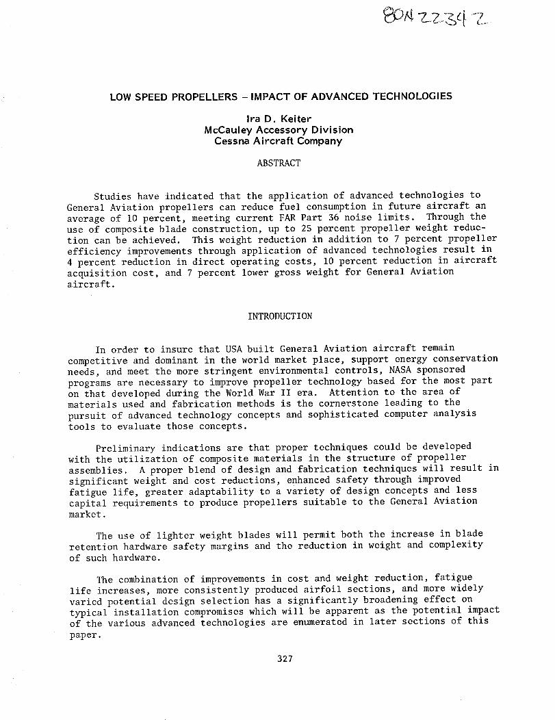
The current research program awarded to McCauley is needed to structure
a realistic and effective technology plan for General Aviation propellers, to
identify the advanced technologies and their potential costs and benefits, and
to determine and identify areas of key technical risks and required research
programs (Figure i). It is hoped that once the areas of greatest potential are
identified, NASA research funding can then be channeled into the most appropri-
ate areas. The team comprising the current study effort (contract number
NAS3-21719) is highlighted in Figure 2.
SENSITIVITY STUDIES
Sensitivity studies were performed to evaluate the potential of each
technology element on propeller performance, noise, weight, and cost for the
following two categories of General Aviation aircraft:
I. Low speed (up to 250 knots)/low power (up to 350 HP), 2 - 8 place,
single and twin engine, currently powered by reciprocating engines.
II. High speed (up to 400 knots)/high power (up to 650 HP), 6 - 18 place,
twin engine, turboprop.
In order to evaluate the improvement potential for the various technology
elements, specific aircraft satisfying the characteristics outlined above for
each category were chosen. The representative aircraft, illustrated in Figure
3, chosen for each aircraft category, are as follows:
Category I Cessna 172N
Cessna 210M
Cessna 414A
Category II : Cessna 441
328

TECHNOLOGYELEMENTSINVESTIGATED
Technology elements were considered with the potential for improvingairplane/mission characteristics such as fuel burned, direct operating cost,acquisition cost, and gross weight. The original scope of technology elementsconsidered were screened to include any element felt to have any potentialwhatsoever based on McCauleyexperience, other's experience, and availableliterature. Each technology element was first evaluated in terms of itseffect on propeller criteria of merit including performance, noise, weight,cost, and structural considerations. The total impact of the technologyelements affecting performance and weight were then investigated to determinetheir impact on airplane/mission characteristics. The General Aviationpropeller concept incorporating the appropriate advanced technologies isillustrated in Figure 4.
PERFORMANCECONSIDERATIONS
The following list of technology elements showpotential for performanceimprovements. The element is specified along with the loss to be minimized,keeping in mind the practical limitations of each of the technology elementsand their impact on other important propeller criteria of merit such as noise,weight, and structure.
Technology Element Performance LossTo BeMinimized
ReferenceUtilized
Design optimizationDecreasedpower loadingIncreased number of bladesMaintain tip speedDecreased activity factorUse of proplets
Use of sweep (helical tip machnumber reduction)
Advancedtechnology airfoil typeDecreased thickness ratioImproved propeller/nacelleintegration
Improved surface finishMaintainability of airfoil shape
Axial momentum 1Tip 1Axial momentum 1Profile 2Tip Purdue Univ.
CompressibilityCompressibility, profileProfile
Blade profile, nacelle drag 2,3Profile 5,6,7Profile 7
The advanced technology concept of sweep is unique since it both improvesperformance and reduces noise. The predicted effect of sweepon performanceand noise is shownin Figure 5. Sweepis structure limited with 25-30 degreesprobably feasible for future General Aviation applications. The effect ofsweepin addition to the effect of other significant advancedtechnology ele-ments on cruise performance gains are shownin Figure 6. Power loading,numberof blades, tip speed, activity factor, and proplets are grouped
329

together and classified as design optimization parameters. Maintainability of
airfoil shape is not included since it is a parameter to prevent degradation
through the use of composites and not to improve current technology.
ACOUSTIC CONSIDERATIONS
The primary technology elements affecting acoustics are number of blades,
tip speed, thickness ratio, activity factor, sweep, blade loading, advanced
technology airfoils, and proplets.
The following is a list of these primary technology elements:
Technology Element References Utilized
Design OptimizationIncreased number of blades
Decreased tip speedDecreased activity factor
Use of proplets
Peak blade loading moved inboard
Use of sweep (helical tip mach number
reduction)
Advanced technology airfoil typesDecreased thickness ratio
Purdue University8
As with performance considerations, several elements are grouped together
under design optimization. From the acoustic standpoint, all items other than
advanced airfoils, sweep, and reduced thickness ratio are considered design
optimization variables. The main technology elements affecting acoustics,
including sweep whose effects were isolated earlier, are shown in Figure 7.
These gains can be realized without any noticeable loss in performance. The
delta dB(A) improvements possible are in many cases more than that required to
meet noise regulations. During design tradeoff studies, the relative
importance of each design parameter must be evaluated. Greater noise reduc-
tions could be obtained if one were willing to sacrifice performance.
MATERIAL CONSIDERATIONS
In order to reliably meet the future performance and acoustic require-
ments of General Aviation propellers with weight reduction and approaching
price competitiveness with aluminum, consideration of composite materials
requires appropriate attention as a viable solution. Advanced filamentarycomposite materials combine low densities and low notch sensitivity with high
strengths and stiffnesses. Adequate safety margins of current propellers canbe further enhanced. Figure 8 outlines the advantages of composites and their
associated propeller benefits. Because filamentary materials are only strongin the filament direction, careful consideration must be given to ply
330

orientation to match the design requirements.
Through variations in the composite matrix, blade sections can be tailored
to meet the specific radial stiffness distribution required. The shape of
primary bending and torsional modes can be altered effectively through the use
of composites. Reductions in blade section size permissible with composites
will result in higher blade deflections than are customary with aluminum.
Blade aeroelastic instabilities can result from large out of plane deflections
and must be given careful consideration.
Appropriate blade materials, type of hub retention system, methods of
construction for composite materials, and material consideration for blade
leading edge erosion resistant strips are all areas which must be addressed in
detail.
STRUCTURAL CONSIDERATIONS
In evaluating the structural integrity of advanced technology propellers,
considerable attention must be given to the steady and alternating loadings
experienced in service. The steady loads consist primarily of centrifugal,
bending due to thrust loading, and torsion. The alternating vibratory loads
are due to blade aerodynamic excitations and alternating torsional input due
to reciprocating engine cylinder firing sequence and frequency. Aerodynamic
inflow angles excite ixP alternating loads which are primarily evident on
turboprop installations being overshadowed by engine alternating torsionals in
reciprocating installations. In all installations one should assure that IxP
resonance does not occur in the normal operating RPM range.
It is a relatively easy job to evaluate the steady loads on a propeller
blade using conventional techniques. To determine the vibratory effects,
however, with incorporation of advanced technologies such as sweep and proplets,
may require the use of three dimensional finite element analysis rather than
two dimensional beam analysis or lumped parameter matrix manipulation techni-
ques currently utilized. With regard to vibratory analysis, available
analytical techniques applicable to General Aviation propellers determine mode
frequencies with good accuracy and vibratory loads and resultant stresses
within 25-30 percent on turbine installations. The effect of alternating
torsionals from reciprocating engines is currently not included in existing
models. Experimental testing of strain gaged propellers is still relied upon
heavily. Experience and experimental data will dictate allowable alternating
stress levels with composites as is the case with aluminum alloys.
Using the torsional mode results from three dimensional finite element
analysis (3-D FEA), the possibilities of stall flutter can be addressed. The
stall flutter parameter is based on static torsional frequency, and semichord,
velocity, and mach number at the 80 percent blade radius location. Through
extensive experimental programs, a stall flutter boundary has been determined
for conventional blade shapes. A similar boundary must be determined for blade
shapes incorporating the advanced technology concepts outlined in Figure 4.
331

Stall flutter occurs under conditions of blade angle of_attack and inflowvelocity where a major portion of the blade is stalled. Stall flutteroscillations occur at the first torsional modewhen the spanwise dampingintegration along a blade becomeszero or less. The conditions conducive tostall flutter are during static, takeoff, and reverse thrust operation.
By using the bending and torsional modedata from 3-D FEAand customarilypresented in terms of a Campbell diagram, classical flutter can be addressed.Classical flutter can occur at high aircraft velocities where the modespacingover the operating RPMrange is insuffient and a coupling of torsional andbending modesoccur (reference 9).
Becauseof the limited composite fatigue strength data available and thelack of analytical techniques to predict vibratory loads, the evaluation offatigue life is highly qualitative. Only through extensive test programs andfield experience, can the required data base of information be compiled fromwhich the appropriate fatigue limits can be determined. This sameprocessoccurred manyyears ago to establish the current baselines utilized foraluminum.
BLADEWEIGHT,COST,ANDAIRCRAFTMISSIONCONSIDERATIONS
Preliminary screening of candidate materials indicates configurations ofE-Glass, S-Glass, Kevlar, and Graphite with mediumand high density epoxy coresto meet the mean load, alternating load, fatigue, and weight requirements ofGeneral Aviation propellers. Relative blade weight and cost comparisonagainst aluminum are shownin Figure 9. In determining the impact of weightreductions through the use of composites it must be emphasizedthat the bladeweight savings exist only with a direct replacement of aluminumblades. Thisdoes not take into account the blade retention area. Also, in order toachieve a desired compromiseof advancedtechnologies between performance andnoise, the potential weight savings maybe reduced. In other words, thetrends of decreased power loading through diameter increases, increased numberof blades, sweep, and proplets will tend to increase weight while being offsetthrough lower blade activity factors and lower thickness ratios (feasiblebecause of composites).
The performance gains indicated earlier in addition to weight reductionspossible through the use of composites have a direct effect on aircraft/mission characteristics such as fuel burned, operating cost, acquisition cost,and gross weight. In addressing mission analysis, payload, range, speed andaircraft lift to drag ratio are kept constant. Potential trip fuel savingsversus aircraft cruise speed are shown in Figure I0. This assumestwo hoursat cruise, felt to be fairly representative. Studies indicate that averagetrip fuel reductions of about I0 percent result in 4 percent reductions indirect operating costs. Included in DOCdetermination are engine and airframeperiodic maintenance, fuel and oil burned, reserves for engine and propelleroverhaul, reserves for avionics, systems and miscellaneous. As fuel pricesraise in the future, their effect on increases in DOCwill be as indicated inFigure ii.
332

Aircraft acquisition cost reductions average about i0 percent.Reductions as affected by aircraft cruise speed are indicated in Figure 12.A twenty-five percent increase in propeller cost has been taken into accountbut does not alter the results since the propeller cost is so low in relationto aircraft cost. Studies also indicate average potential aircraft grossweight reductions of seven percent.
FUTURERECOMMENDATIONS
It is apparent from the sensitivity studies performed on the varioustechnology elements that NASAfunding directed primarily into the areas ofcomposite materials research, and the advancedtechnology concepts outlined inthis paper can provide the data base required to achieve the stated airplane/mission improvements.
Since manytechnology elements improving performance have an adverseeffect on acoustics and future government regulations controlling noise limitswill probably be more stringent, it is imperative that research funding beexpendedin this area. This should include careful evaluation of currentmethodology of propeller noise prediction techniques and the unification intoa common,recognized procedure for utilization by the General Aviationcommunity. Experimental verification of resulting theories through wind tunneltesting and flight substantiation is necessary.
Through the use of composites, someof the more promising technologyrequirements will becomepossible such as thickness ratio reductions, sweep,lower activity factors, reduced power loading, more blades, advanced airfoilswith complex curvature, smoother airfoil surface, and maintainability of air-foil shape in service. These factors lead to optimized designs meetingappropriate strength requirements. At a certain blade load level, thecomposite blade will deflect more. This can lead to aeroelastic instabilitieswhich is an important area requiring NASAsupport. Although considerableresearch has taken place in the composite materials area, the product applica-tions have not included propellers. The aircraft propeller is one of the mostcritically stressed aircraft components. It operates in a severe environmentand is a major structural componentwith complex stress distribution. It isexposed to the wide range of variables created by power plants in a mostintimate manner. The successful use of composite materials in General Aviationpropellers will provide information on fatigue to establish limit lines ofmeanstress versus alternating stress for 105 and 108 cycles as typicallyrepresented on a Goodmandiagram. Such information is not readily obtainablein any other application.
NASAsponsored research will help fill the gap in the application ofcomposite technology (design and fabrication methods) between current applica-tions and their potential use with propellers. Advancedcomposites technologyhas progressed to a point where reliable application as aircraft secondarystructure is accepted and the application for primary structure is relativelyclose but the confidence level for commercial application has not beenestablished. It is, therefore, highly desirable and appropriate to explore
333

this General Aviation application,
Specifically, the total cost of composite blades must be nearly competi-tive with aluminum blades in order to experience wide use in General Aviation.Research into low cost fabrication techniques is the key to achieving costcompetitiveness. Wind tunnel testing with follow-on programs for flight testverification is necessary.
In the advancedairfoil design area, NASAhas continually madeefforts inimproving communication with the General Aviation community over the past fiveyears through workshops, symposiums, conferences, etc., and from these havecomeairfoil design implementation schedules satisfying the needs of wingdesigners. What is needed now is an airfoil technology plan to design airfoilsspecifically tailored for the widely varying fluid flow conditions whichprevail along a propeller blade.
The area of propeller/nacelle integration is already receiving someattention by NASAwith Grant NSGI402to Mississipi State University. Thefirst phase involving the collection of baseline data in the NASA-Langleyfullscale tunnel is just getting underway. Current program calls for investigationof nacelle shapes characteristic of those used in twin reciprocating engineinstallations. There should be future testing including a wide variety ofpropeller/nacelle configurations covering the broad range of aircraft/enginecombinations typical of the General Aviation fleet.
NASAhas supported analytical studies to provide special purpose useroriented programs to calculate propeller inflow velocity fields, steady andunsteady aerodynamic loads and modeshapes and frequencies. The next stepshould be to concentrate on analytical procedures to predict the vibrationalloads and stresses the propeller is subjected to in service. The model mustinclude the coupling effects of the propeller-engine system. Accuracy ofexisting prediction techniques is not acceptable except for ixP analysis.Higher order stresses prevalent with reciprocating engine installations arenot predicted with adequate accuracy. A good, reliable prediction techniquewould eliminate muchof the uncertainty which exists prior to vibration surveycertification testing. Wastedtime and cost associated with experimental test-ing of a configuration exceeding vibratory load limits could be nearlyeliminated.
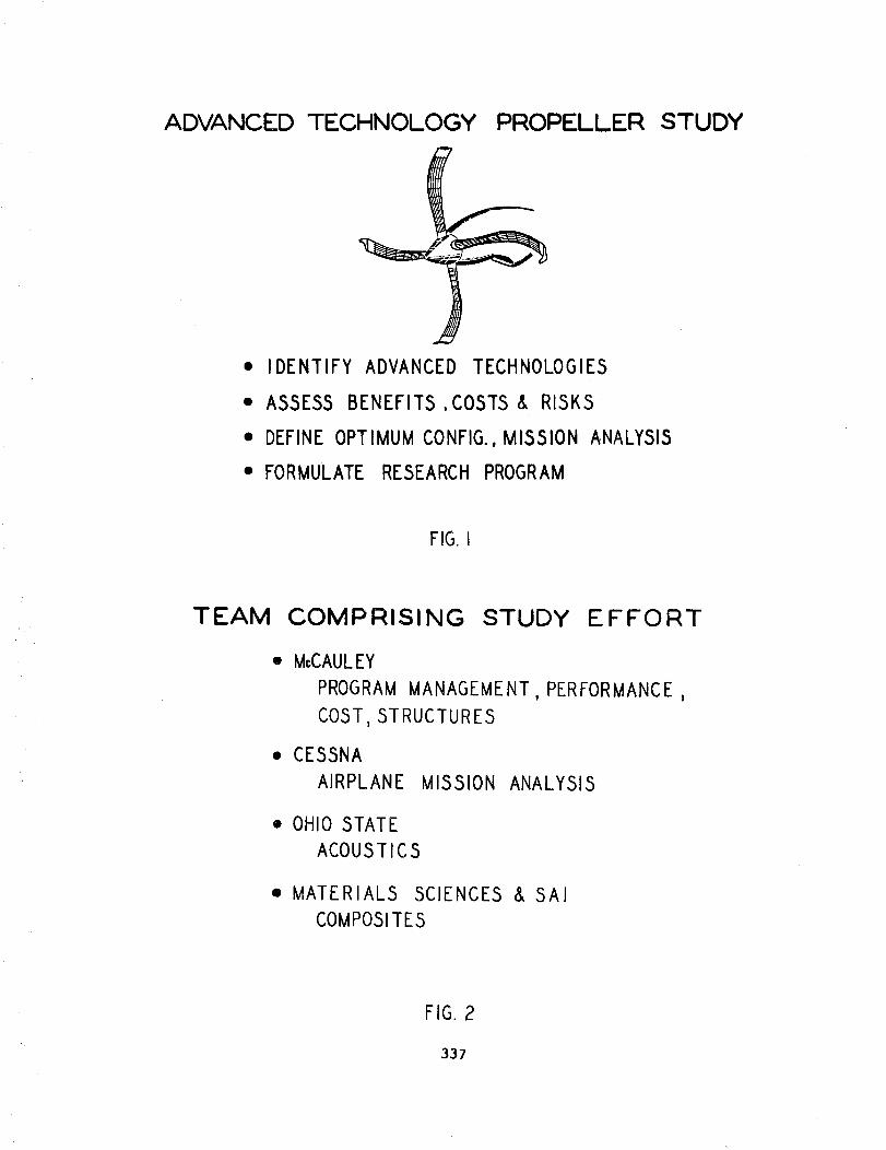
With the very competitive market in General Aviation which limits fundsin research and development, it is very evident that NASAsponsored supportis necessary to enhance the state of the art in the areas mentioned above.The key areas requiring future research enumeratedabove are highlighted inFigure 13.
CONCLUDINGREMARKS
The study of a wide range of propeller design variables and advancedtechnologies has indicated that the potential exists for propeller performanceimprovementsand weight reductions meeting consistently more stringentregulatory noise levels. Advancedtechnological development of propellers has
334

a direct impact on the fuel burned, direct operating costs, acquisition cost,and gross weight of General Aviation aircraft. NASAcan assure that thesegoals are met by allocating appropriate funds in the areas where the greatestpotential exists.
335

REFERENCES
i. Anonymous: SBAC-Standard Method of Propeller Performance Estimation,
Society of British Aircraft Constructors, Ltd. April 1950.
2. Goldstein, S.: On The Vortex Theory of Screw Propellers. Royal Society
(London) Proc., 1929.
3. Hess, J.L.; and Smith, A.M.O.: Calculation of Potential Flow About
Arbitrary Bodies. Progress in Aeronautical Sciences, vol. 8, 1967,
pp.l-138.
4. Bocci, A.J.: A New Series of Aerofoil Sections Suitable For Aircraft
Propellers. Aeronautical Quarterly, vol. 28, Part I, Feb. 1977, pp.59-73.
5. Hoerner, S.F.: Fluid-Dynamic Drag. 1965.
6. Hoerner, S.F.; and Borst, H.V.: Fluid-Dynamic Lift. 1975.
7. Stevens, W.A.; Goradia, S.H.; and Braden, J.A.: Mathematical Model For Two-
Dimensional Multi-Component Airfoils In Viscous Flow. NASA CR-1843,
July 1971.
8. Succi, George P.: Design of Quiet Efficient Propellers, SAE Paper 790584,
SAE Business Aircraft Meeting, Wichita, April 1979.
9. Dugan, J.F. Jr.; Gatzen, B.S.; and Adamson, W.M.: Prop-Fan Propulsion-lts
Status and Potential. SAE Paper 780995, SAE Aerospace Meeting, San Diego,November 1978.
336
ADVANCED TECHNOLOGY PROPELLER
• IDENTIFY ADVANCED TECHNOLOGIES
• ASSESS BENEFITS ,COSTS& RISKS
• DEFINE OPTIMUM CONFIG., MISSION ANALYSIS
• FORMULATE RESEARCH PROGRAM
STUDY
FIG. I
TEAM COMPRISING STUDY EFFORT
• McCAULEY
PROGRAM MANAGEMENT, PERFORMANCE ,
COST, STRUCTURES
• CESSNA
AIRPLANE MISSION ANALYSIS
• OHIO STATE
ACOUSTICS
• MATERIALS SCIENCES & SAI
COMPOSITES
FIG.2
337

BASELINE AIRCRAFT STUDIED
44
FIG. 3
ADVANCED TECHNOLOGY CONCEPTS
I
BLADE SHAPESand
AIRFOILS
COMPO.cSURFACE FINISH
FIG. 4
TIP DEVICES
PROPLETS
PROP/NACELLEINTEGRATION
338

PREDICTED EFFECT OF SWEEP ONPERFORMANCE AND NOISE
RELATIVEEFF.
3 0
2
0
" "- _... NOISE
0° 15" 3'0° 4!
I RELATIVENOISEAdB(A)
2
°3
TIP SWEEP
FIG.5
POTENTIAL CRUIS E
8
PERFORMANCE GAINS
7.0
EFF.GAIN
4
2
SWEEP ADV.AIRFOILS, PROP/NAC DESIGNSURFACE INTEGRATION OPTIM.
FINISH
FIG.6
TOTAL
339

POTENTIAL
10
NOISERED.
dB(A)
6
4
2
ADV.AIRFOILS
FLYOVER
1.0
ISWEEP
NOISE
2.0
1THICKNESS
RATIO
REDUCTIONS
5.5
DESIGN TOTALOPTIM.
FIG. 7
BENEFITS OF
COMPOSITEA DVANTAGES
COMPOSITE MATERIALS
PROPELLERBENEFITS
GREATER STRENGTH
LOWER DENSITY
HIGHER MODULUS
LOWER NOTCHSENSITIVITY
LOWER WEIGHT
IMPROVED PERFORMANCE
LOWER NOISE
ENHANCED SAFETYMARGIN
FIG. 8
340

BLADE WEIGHT AND COST COMPARISON
2.0"
1.8'
1.6
REL. 1.4'WEIGHT 1.2-
AND 1.0-
COST .8-
.6-
.4-
.2"
.0
MAT'L COST!_ MFG. COST
WEIGHT
ALUM. E-GLASS S-GLASS KEVLAR GRAPHITE
FIG.9
POTENTIAL TRIP FUEL SAVINGS
15
TRIP FUEL I0SAVINGS
5
o '10o
FAR 36 __1
172. 210 414
1io 200 250CRUISESPEED(KNOTS)
FIG. 10
360
341

FUEL PRICE EFFECTS ONDIRECT OPERATING COSTS
DIRECTOPER. COSTS
(% INC.)
70
60
50
40
30
20
10
0
-10
CURRENT
TECHNOL_..--""---
/.11" ADVANCED
/ TECHNOLOGY
/
]4%
FUEL PRICE $/GAL
FIG. II
AIRCRAFTACQUISITION COST REDUCTIONS
COSTREDUCTION
(A_)
15
10
5
o 10o
441
i_;o 200 zso
CRUISE SPEED (KNOTS)
30o
FIG.12
342
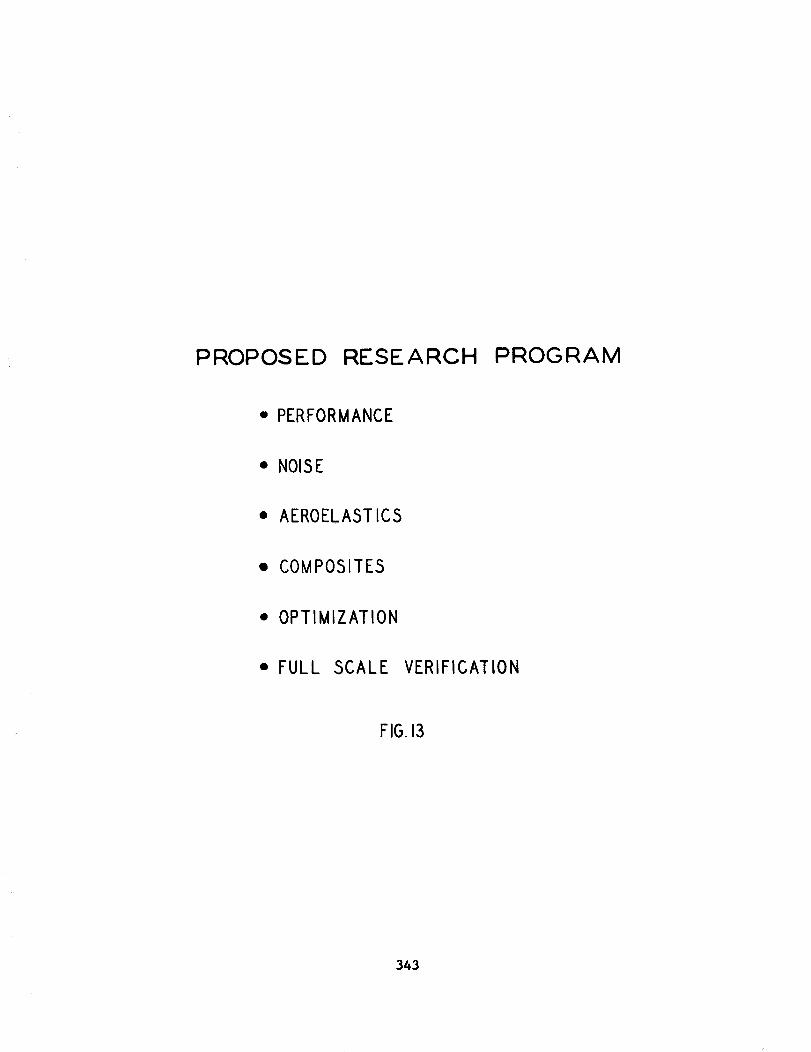
PROPOSED RESEARCH PROGRAM
• PERFORMANCE
• NOISE
• AEROELASTICS
• COMPOSITES
• OPTIMIZATION
• FULL SCALE VERIFICATION
FIG.13
343

Related Documents