Catalog number A-014 rev-NC • Four power contact options: 55 amps, 38 amps, 12 amps and 3 amps versions plus high density signal lines. • Blind mating, float mount, panel mount and cable connector options with unique locking system. • Ventilation option to offer increased air cooling. LOW PROFILE SCORPION Slim Modular Power & Signal Contact Connectors ®

Welcome message from author
This document is posted to help you gain knowledge. Please leave a comment to let me know what you think about it! Share it to your friends and learn new things together.
Transcript

Catalog number A-014 rev-NC
• Fourpowercontactoptions:
55amps,38amps,12ampsand3ampsversions
plushighdensitysignallines.
• Blindmating,floatmount,panelmountand
cableconnectoroptionswithuniquelockingsystem.
• Ventilationoptiontoofferincreasedaircooling.
LO
W P
RO
FIL
E S
CO
RP
ION
Slim
Mod
ula
r P
ow
er
& S
ign
al C
on
tact
Con
necto
rs
®

2 3
Positronic Industrieswww.connectpositronic.comwww.positronicasia.com
Positronic Industrieswww.connectpositronic.com
www.positronicasia.com
Ordering Information - Code Numbering System
Specify complete connector by selecting an option from step 1 through 9(Consult sales for connectors’ length exceeding 101mm or part numbers using more than 30 characters)
Notes:1 A Low Profile Scorpion part number can be a maximum of 30 characters. If the connector configuration exceeds this number, please consult sales for a special part number for your unique requirement.2 Consult sales for connector length exceeding 101.00 mm [3.976 inch].3 Alignment bar is only available for size 20 and size 22 right angle (90°) contacts.
STEP 1 2 3 4 5
Example LSP 2 YKNRS 4 M
STEP 1: BASIC SERIESLSP : Low Profile Scorpion Series.
STEP 11: SPECIAL OPTIONSConsult sales for Special Options
STEP 2: GUIDE AND LOCKING OPTIONS2 : Blind Mating System.3 : Locking Latch System, for cable to cable connectors only.4 : Locking Latch System, for male cable to female panel/board connectors only.5 : Locking Latch System, for female cable to male panel/board connectors only.
STEP 10: ENVIRONMENTAL COMPLIANCE OPTIONS/AA : Compliant per EU Directive 2002/95/EC (RoHS)Example: LSP5YN2HK4M000A1/AANote: This step will not be used if compliance to environmental legislation is not required.Example: LSP5YN2HK4M000A1
STEP 9: CONTACT PLATING1 : Crimp contacts ordered separately.A1 : Gold flash over nickel on mating end termination end.A2 : Gold flash over nickel on mating end and 0.005[0.0002] tin-lead solder coat on termination end. Not available with code 93, 938 in step 4.C1 : 0.00076[0.000030] gold over nickel on mating end and termination end.C2 : 0.00076[0.000030] gold over nickel on mating end and 0.005[0.0002] tin-lead solder coat on termination end. Not available with code 93, 938 in step 4.D1 : 0.00127[0.000050] gold over nickel on mating end and termination end.D2 : 0.00127[0.000050] gold over nickel on mating end and 0.005[0.0002] tin-lead solder coat on termination end. Not available with code 93, 938 in step 4.
Consult sales for availability of silver plating.
STEP 7: MOUNTING STYLE0 : Not applicable / No additional accessories.B : 90° metal mounting bracket (through hole), for right angle PCB mounted connectors use code 4 or 48, see step 4.LN : 90° metal mounting bracket (board lock), for right angle PCB mounted connectors use code 4 or 48, see step 4.N : Push-on fastener for PCB mounted connectors use code 3, 38, 4 or 48, see step 4.
STEP 6: PANEL MOUNT0 : Not applicable / No added accessories.6 : Easy release mounting clip for 1.50mm [0.059 inch] thick panel, for male panel mount connector only.82 : Float mount for 1.50 mm [0.059 inch] thick panel.83 : Float mount for 2.30 mm [0.091 inch] thick panel.
STEP 4: CONTACT TERMINATION TYPE1 : Crimp contacts, order separately.3 : Solder, straight PCB mount.38 : Solder, straight PCB mount. High conductivity power contacts.4 : Solder, right angle (90°) PCB mount.48 : Solder, right angle (90°) PCB mount. High conductivity power contacts.*93 : Press-fit compliant terminations, straignt PCB mount, for use with PCB not thinner than 2.29[0.090].*938 : Press-fit compliant terminations, straignt PCB mount, for use with PCB not thinner than 2.29[0.090]. High conductivity power contacts.
* Consult sales for availability of press-fit compliant terminations or mixed contact termination type.
STEP 8: VENT OPTIONS (For power contacts)0 : Connector body is not vented.9 : Connector body vented for air cooling.
STEP 5: CONNECTOR GENDERM : MaleF : Female - Standard contacts.S : Female - Posiband contacts
STEP 3: CONNECTOR VARIANTSSize 12 power contact module, E or Y or G
Size 20 power contact module, R or S or U
Size 22 signal contact module, H or J or K or T
Blank module, N or N2 or N3 or N4
Consult sales for availability of other modules.It is recommended signal contacts are positioned at the center of connector.
6 7 8 9 10 11
0 N 9 A1 /AA - XXX
LSP2Female
Female Female
Female
Male
Male Male
Male
LSP4
LSP3
Code 0
Code 6
Code 9
Code 82 or 83
LSP5
E Y G
H J K T
N N2 N3 N4
R S U
Code LN Code NCode B
1
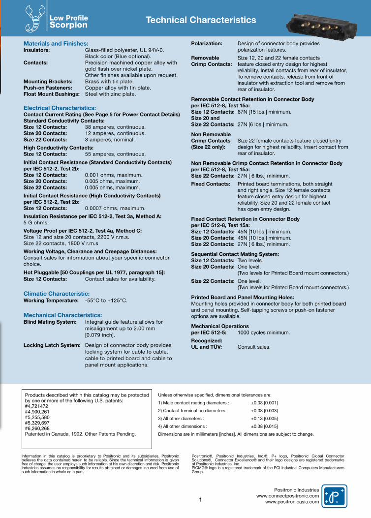
Materials and Finishes:Insulators: Glass-filled polyester, UL 94V-0. Black color (Blue optional). Contacts: Precision machined copper alloy with gold flash over nickel plate. Other finishes available upon request.Mounting Brackets: Brass with tin plate.Push-on Fasteners: Copper alloy with tin plate.Float Mount Bushings: Steel with zinc plate.
Electrical Characteristics:Contact Current Rating (See Page 5 for Power Contact Details)Standard Conductivity Contacts:Size 12 Contacts: 38 amperes, continuous.Size 20 Contacts: 12 amperes, continuous.Size 22 Contacts: 3 amperes, nominal.
High Conductivity Contacts:Size 12 Contacts: 55 amperes, continuous.
Initial Contact Resistance (Standard Conductivity Contacts) per IEC 512-2, Test 2b:Size 12 Contacts: 0.001 ohms, maximum.Size 20 Contacts: 0.005 ohms, maximum.Size 22 Contacts: 0.005 ohms, maximum.
Initial Contact Resistance (High Conductivity Contacts)per IEC 512-2, Test 2b:Size 12 Contacts: 0.0007 ohms, maximum.
Insulation Resistance per IEC 512-2, Test 3a, Method A: 5 G ohms.
Voltage Proof per IEC 512-2, Test 4a, Method C: Size 12 and size 20 contacts, 2200 V r.m.s. Size 22 contacts, 1800 V r.m.s
Working Voltage, Clearance and Creepage Distances:Consult sales for information about your specific connector choice.
Hot Pluggable [50 Couplings per UL 1977, paragraph 15]:Size 12 Contacts: Contact sales for availability.
Climatic Characteristic:Working Temperature: -55°C to +125°C.
Mechanical Characteristics:Blind Mating System: Integral guide feature allows for misalignment up to 2.00 mm [0.079 inch].
Locking Latch System: Design of connector body provides locking system for cable to cable, cable to printed board and cable to panel mount applications.
Polarization: Design of connector body provides polarization features.
Removable Size 12, 20 and 22 female contacts Crimp Contacts: feature closed entry design for highest reliability. Install contacts from rear of insulator, To remove contacts, release from front of insulator with extraction tool and remove from rear of insulator.
Removable Contact Retention in Connector Bodyper IEC 512-8, Test 15a: Size 12 Contacts: 67N [15 lbs.] minimum.Size 20 and Size 22 Contacts: 27N [6 lbs.] minimum.
Non Removable Crimp Contacts Size 22 female contacts feature closed entry (Size 22 only): design for highest reliability. Insert contact from rear of insulator.
Non Removable Crimp Contact Retention in Connector Bodyper IEC 512-8, Test 15a:Size 22 Contacts: 27N [ 6 lbs.] minimum.
Fixed Contacts: Printed board terminations, both straight and right angle. Size 12 female contacts feature closed entry design for highest reliability. Size 20 and 22 female contact has open entry design.
Fixed Contact Retention in Connector Bodyper IEC 512-8, Test 15a:Size 12 Contacts: 45N [10 lbs.] minimum.Size 20 Contacts: 45N [10 lbs.] minimum.Size 22 Contacts: 27N [ 6 lbs.] minimum.
Sequential Contact Mating System:Size 12 Contacts: Two levels. Size 20 Contacts: One level. (Two levels for Printed Board mount connectors.)
Size 22 Contacts: One level. (Two levels for Printed Board mount connectors.)
Printed Board and Panel Mounting Holes:Mounting holes provided in connector body for both printed board and panel mounting. Self-tapping screws or push-on fastener options are available.
Mechanical Operations per IEC 512-5: 1000 cycles minimum.
Recognized: UL and TÜV: Consult sales.
Technical Characteristics
Positronic Industrieswww.connectpositronic.com
www.positronicasia.com
Information in this catalog is proprietary to Positronic and its subsidiaries. Positronic believes the data contained herein to be reliable. Since the technical information is given free of charge, the user employs such information at his own discretion and risk. Positronic Industries assumes no responsibility for results obtained or damages incurred from use of such information in whole or in part.
Positronic®, Positronic Industries, Inc.®, P+ logo, Positronic Global Connector Solutions®, Connector Excellence® and their logo designs are registered trademarks of Positronic Industries, Inc.PICMG® logo is a registered trademark of the PCI Industrial Computers Manufacturers Group.
Unless otherwise specified, dimensional tolerances are:
1) Male contact mating diameters : ±0.03 [0.001]
2) Contact termination diameters : ±0.08 [0.003]
3) All other diameters : ±0.13 [0.005]
4) All other dimensions : ±0.38 [0.015]
Dimensions are in millimeters [inches]. All dimensions are subject to change.
Products described within this catalog may be protected by one or more of the following U.S. patents:#4,721472#4,900,261#5,255,580#5,329,697#6,260,268Patented in Canada, 1992. Other Patents Pending.
Low Profile Scorpion
Positronic Industrieswww.connectpositronic.com
www.positronicasia.com
Low Profile Scorpion
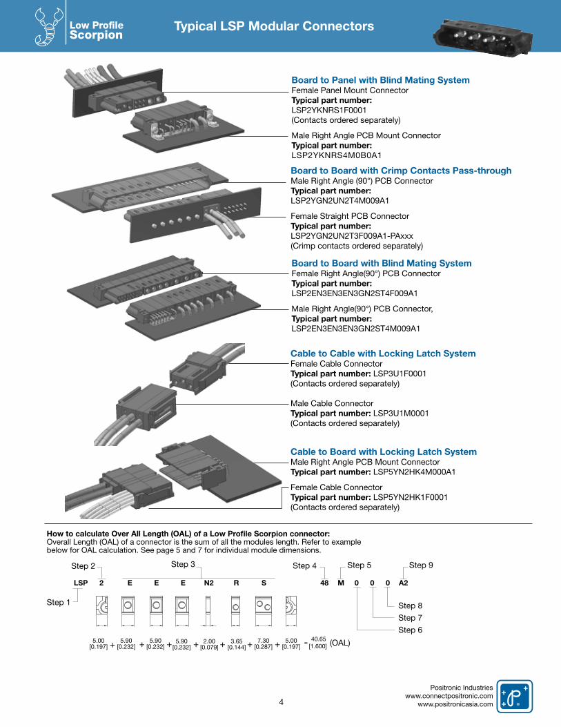
Typical LSP Modular Connectors
Board to Panel with Blind Mating SystemFemale Panel Mount ConnectorTypical part number:LSP2YKNRS1F0001(Contacts ordered separately)
Male Right Angle PCB Mount ConnectorTypical part number:LSP2YKNRS4M0B0A1
Board to Board with Blind Mating SystemFemale Right Angle(90°) PCB ConnectorTypical part number:LSP2EN3EN3EN3GN2ST4F009A1
Male Right Angle(90°) PCB Connector,Typical part number:LSP2EN3EN3EN3GN2ST4M009A1
Board to Board with Crimp Contacts Pass-throughMale Right Angle (90°) PCB ConnectorTypical part number: LSP2YGN2UN2T4M009A1
Female Straight PCB Connector Typical part number: LSP2YGN2UN2T3F009A1-PAxxx(Crimp contacts ordered separately)
Cable to Cable with Locking Latch SystemFemale Cable ConnectorTypical part number: LSP3U1F0001(Contacts ordered separately)
Male Cable ConnectorTypical part number: LSP3U1M0001(Contacts ordered separately)
Cable to Board with Locking Latch SystemMale Right Angle PCB Mount ConnectorTypical part number: LSP5YN2HK4M000A1
Female Cable ConnectorTypical part number: LSP5YN2HK1F0001(Contacts ordered separately)
4
LSP 2 E E E N2 R S 48 M 0 0 0 A2
Step 1
Step 5 Step 3
Step 8
Step 9
Step 7
Step 6
Step 2 Step 4
5.90 [0.232]
3.65 [0.144]
5.90 [0.232]
5.00[0.197]
5.90 [0.232]
5.00[0.197]
7.30 [0.287] + + + + + + + =
40.65 [1.600]
How to calculate Over All Length (OAL) of a Low Profile Scorpion connector: Overall Length (OAL) of a connector is the sum of all the modules length. Refer to examplebelow for OAL calculation. See page 5 and 7 for individual module dimensions.
(OAL) 2.00[0.079]
Positronic Industrieswww.connectpositronic.comwww.positronicasia.com
Low Profile Scorpion
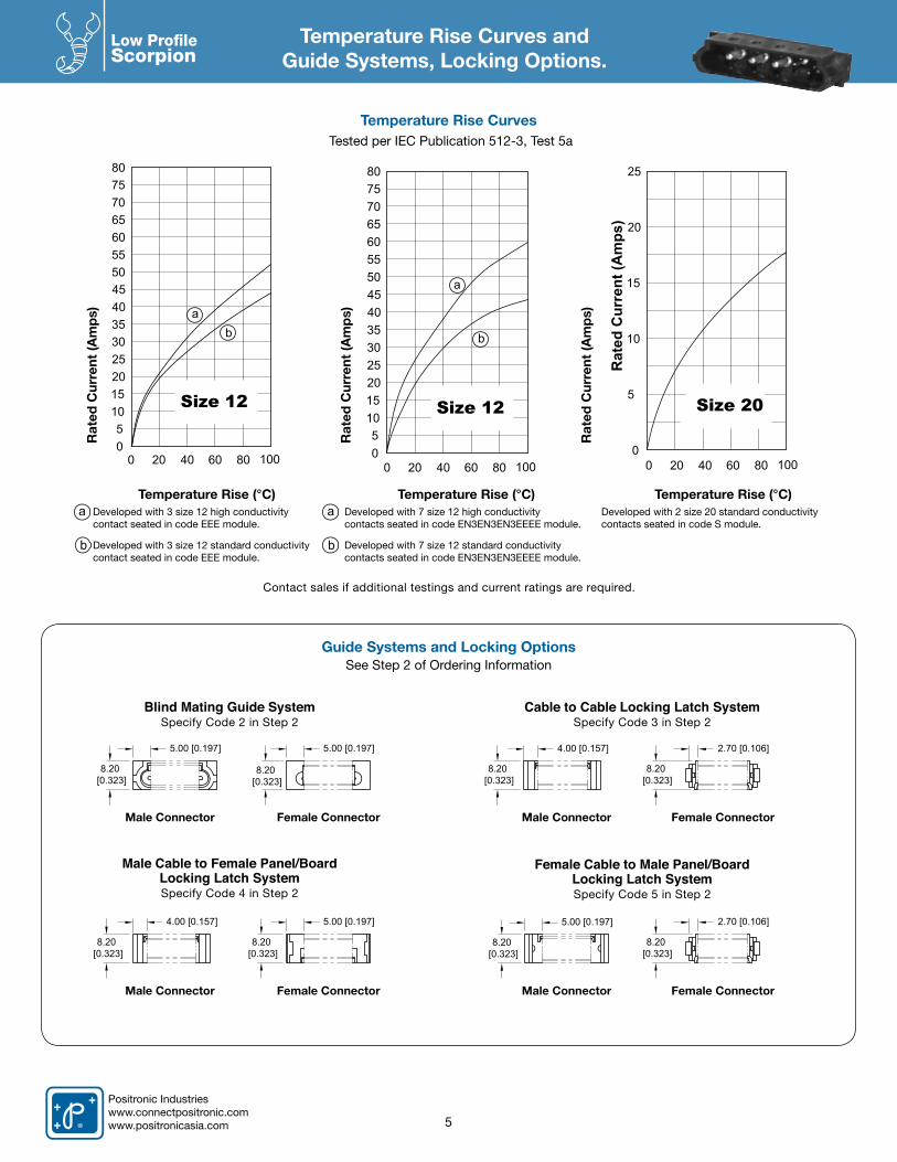
Temperature Rise Curves andGuide Systems, Locking Options.
Tested per IEC Publication 512-3, Test 5a
Temperature Rise (°C)Developed with 3 size 12 high conductivitycontact seated in code EEE module.
Developed with 3 size 12 standard conductivitycontact seated in code EEE module.
Temperature Rise (°C)Developed with 7 size 12 high conductivitycontacts seated in code EN3EN3EN3EEEE module.
Developed with 7 size 12 standard conductivitycontacts seated in code EN3EN3EN3EEEE module.
Temperature Rise (°C)Developed with 2 size 20 standard conductivity contacts seated in code S module.
Rat
ed C
urre
nt (A
mp
s)
Rat
ed C
urre
nt (A
mp
s)
Rat
ed C
urre
nt (A
mp
s)
a a
b b
5
Temperature Rise Curves
Guide Systems and Locking OptionsSee Step 2 of Ordering Information
Blind Mating Guide SystemSpecify Code 2 in Step 2
Male Cable to Female Panel/BoardLocking Latch SystemSpecify Code 4 in Step 2
Cable to Cable Locking Latch SystemSpecify Code 3 in Step 2
Female Cable to Male Panel/BoardLocking Latch SystemSpecify Code 5 in Step 2
Male Connector
Male Connector
Male Connector Female Connector Female Connector
Male Connector Female Connector Female Connector
Size 12
05
101520253035404550556065707580
10002 04 06 08 0
ba
Size 20
Rat
ed C
urre
nt (A
mps
)
02 04 06 08 0 1000
5
10
15
20
25
Contact sales if additional testings and current ratings are required.
5.00 [0.197]
8.20 [0.323]
8.20 [0.323]
5.00 [0.197]
8.20 [0.323]
4.00 [0.157]
8.20 [0.323]
2.70 [0.106]
8.20 [0.323]
4.00 [0.157]
8.20 [0.323]
5.00 [0.197]
8.20 [0.323]
5.00 [0.197]
8.20 [0.323]
2.70 [0.106]
Size 12
b
05
101520253035404550556065707580
10002 04 06 08 0
a
Positronic Industrieswww.connectpositronic.com
www.positronicasia.com
Low Profile Scorpion
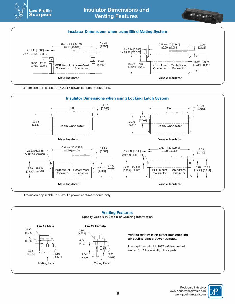
Insulator Dimensions andVenting Features
Insulator Dimensions when using Blind Mating System
Venting FeaturesSpecify Code 9 in Step 8 of Ordering Information
Insulator Dimensions when using Locking Latch System
6
Male Insulator
Male Insulator
Size 12 Male
Male Insulator
* Dimension applicable for Size 12 power contact module only.
* Dimension applicable for Size 12 power contact module only.
Venting feature is an outlet hole enabling air cooling onto a power contact.
In compliance with UL 1977 safety standard, section 10.2 Accessibility of live parts.
Female Insulator
Female Insulator
Size 12 Female
Female Insulator
17.50 [0.689]
23.62 [0.930]
2x Ø1.93 [Ø0.076]
OAL 4.20 [0.165] ±0.20 [±0.008]
2x 2.10 [0.083]
18.30 [0.720]
* 2.20 [0.087]
PCB Mount Connector
PCB Mount Connector
PCB Mount Connector
PCB Mount Connector
Cable/PanelConnector
Cable/PanelConnector
Cable/PanelConnector
Cable/PanelConnector
Cable Connector
Mating Face Mating Face
Cable Connector
20.90 [0.823]
2x Ø1.93 [Ø0.076]
20.75 [0.817]
2.10 [0.083]
7.20 [0.283]
18.70 [0.736]
OAL 4.20 [0.165] ±0.20 [±0.008]
* 3.20 [0.126]2x
OAL
23.62 [0.930]
* 2.20 [0.087]
20.75 [0.817]
OAL
9.25 [0.364]
* 3.20 [0.126]
17.50 [0.689]
23.62 [0.930]
2x Ø1.93 [Ø0.076]2x 2.10 [0.083]
OAL 4.20 [0.165] ±0.20 [±0.008]
18.30 [0.720]
2x3.10 [0.122]
* 2.20 [0.087]
20.75 [0.817]
18.70 [0.736]
OAL 4.20 [0.165] ±0.20 [±0.008]2x 2.10 [0.083]
2x Ø1.93 [Ø0.076]
19.50 [0.768]
2x 3.10 [0.122]
* 3.20 [0.126]
4.00 [0.157]
2.00 [0.079] 4.50
[0.177]
5.90 [0.232]
4.00 [0.157]
2.00 [0.079]
2.50 [0.098]
5.90 [0.232]
Positronic Industrieswww.connectpositronic.comwww.positronicasia.com
Low Profile Scorpion
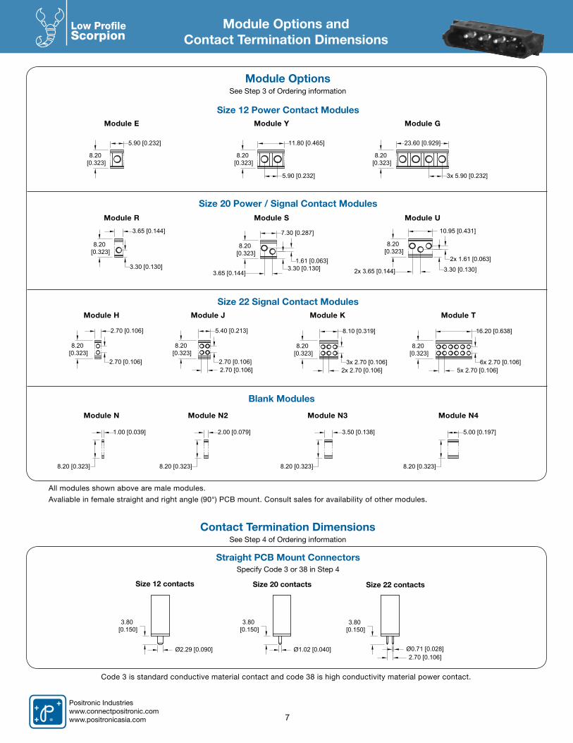
Module Options andContact Termination Dimensions
Size 12 Power Contact Modules
Straight PCB Mount ConnectorsSpecify Code 3 or 38 in Step 4
Size 20 Power / Signal Contact Modules
Size 22 Signal Contact Modules
Blank Modules
All modules shown above are male modules.
Avaliable in female straight and right angle (90°) PCB mount. Consult sales for availability of other modules.
Module R
Module E
Module H
Module N
Module J
Module N2
Module K
Module N3
Module T
Module N4
Module S
Module Y
Module U
Module G
7
5.90 [0.232]
8.20 [0.323]
5.90 [0.232]
11.80 [0.465]
8.20 [0.323]
23.60 [0.929]
3x 5.90 [0.232]
8.20 [0.323]
3.65 [0.144]
8.20 [0.323]
3.30 [0.130]
7.30 [0.287]
8.20 [0.323]
1.61 [0.063]
3.65 [0.144]3.30 [0.130]
10.95 [0.431]
2x 3.65 [0.144]
8.20 [0.323]
2x 1.61 [0.063]
3.30 [0.130]
2.70 [0.106]
2.70 [0.106]
8.20 [0.323]
5.40 [0.213]
2.70 [0.106]2.70 [0.106]
8.20 [0.323]
8.10 [0.319]
3x 2.70 [0.106]2x 2.70 [0.106]
8.20 [0.323]
16.20 [0.638]
8.20 [0.323]
6x 2.70 [0.106]5x 2.70 [0.106]
1.00 [0.039]
8.20 [0.323]
2.00 [0.079]
8.20 [0.323]
3.50 [0.138]
8.20 [0.323]
5.00 [0.197]
8.20 [0.323]
Size 12 contacts Size 20 contacts Size 22 contacts
Code 3 is standard conductive material contact and code 38 is high conductivity material power contact.
Ø2.29 [0.090]
3.80 [0.150]
Ø1.02 [0.040]
3.80 [0.150]
Ø0.71 [0.028]
3.80 [0.150]
2.70 [0.106]
Module OptionsSee Step 3 of Ordering information
Contact Termination DimensionsSee Step 4 of Ordering information
Positronic Industrieswww.connectpositronic.com
www.positronicasia.com
Low Profile Scorpion
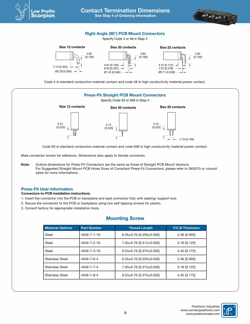
Contact Termination DimensionsSee Step 4 of Ordering information
Size 12 contacts
Size 12 contacts
Size 20 contacts
Size 20 contacts
Size 22 contacts
Size 22 contacts
Right Angle (90°) PCB Mount ConnectorsSpecify Code 4 or 48 in Step 4
Press-Fit Straight PCB Mount ConnectorsSpecify Code 93 or 938 in Step 4
Code 93 is standard conductive material contact and code 938 is high conductivity material power contact.
Male connector shown for reference. Dimensions also apply to female connector.
Note: Outline dimensions for Press-Fit Connectors are the same as those of Straight PCB Mount Versions. For Suggested Straight Mount PCB Holes Sizes of Compliant Press-Fit Connectors, please refer to SK6370 or consult sales for more informations.
Code 4 is standard conductive material contact and code 48 is high conductivity material power contact.
8
7.72 [0.304]
3.80 [0.150]
Ø2.29 [0.090]
3.80 [0.150]
4.91 [0.194]6.52 [0.257]Ø1.02 [0.040]
3.80 [0.150]
4.37 [0.172]7.07 [0.278]Ø0.71 [0.028]
5.72 [0.225]
5.72 [0.225]
5.72 [0.225]
2.70 [0.106]
Press-Fit User Information Connectors-to-PCB installation instructions:
1. Insert the connector into the PCB or backplane and seat connector fully with seating/ support tool.
2. Secure the connector to the PCB or backplane using two self-tapping screws for plastic.
3. Consult factory for appropriate installation tools.
Mounting Screw
Material Options Part Number Thread Length P.C.B Thickness
Steel 4546-7-1-16 6.35±0.76 [0.250±0.030] 2.36 [0.093]
Steel 4546-7-2-16 7.93±0.76 [0.312±0.030] 3.18 [0.125]
Steel 4546-7-3-16 9.53±0.76 [0.375±0.030] 4.45 [0.175]
Stainless Steel 4546-7-6-4 6.35±0.76 [0.250±0.030] 2.36 [0.093]
Stainless Steel 4546-7-7-4 7.93±0.76 [0.312±0.030] 3.18 [0.125]
Stainless Steel 4546-7-8-4 9.53±0.76 [0.375±0.030] 4.45 [0.175]

Positronic Industrieswww.connectpositronic.comwww.positronicasia.com
Low Profile Scorpion
9
Accessories
Easy Release Mounting ClipsSpecify code 6 in Step 6
Float Mount BushingsSpecify Code 82 or 83 in Step 6
Material and Finish: Steel with zinc plate.
Material and Finish: Beryllium copper with nickel plate.For male connector only.
Accessories for Panel MountSee Step 6 of Ordering Information
Code Panel Thickness Dimension F
82 1.50 [0.059] 1.80 [0.071]
83 2.30 [0.091] 2.60 [0.102]
OAL 4.20 [0.165]±0.20 [±0.008] F
OAL 4.20 [0.165]±0.20 [±0.008]
90° Through Hole BracketsSpecify code B in Step 7
90° Board Lock BracketsSpecify code LN in Step 7
Push-on FastenersSpecify code N in Step 7
Accessories for PCB MountSee Step 7 of Ordering Information
Male connector shown for reference only. Consult sales for mounting screw information.
Straight PCB Mount Connector Right Angle (90°) PCB Mount Connector
Material and Finish: Brass with tin plate.
Material and Finish: Copper alloy with tin plate.
Material and Finish: Brass with tin plate.
2x Ø2.54 [Ø0.100]
7.00 [0.276]OAL 4.20 [0.165]
±0.20 [±0.008]
6.90 [0.272]
3.43 [0.135]
OAL 4.20 [0.165]±0.20 [±0.008]
6.90 [0.272]
2.80 [0.110]
Ø2.06 [0.081]
For Mounting ScrewsSpecify code 0 in Step 6
For Float MountingSpecify code 82 or 83 in Step 6
For Quick Release Mounting ClipSpecify code 6 in Step 6
(Maximum panel thickness:1.60 [0.063] nominal)
Panel Cutout Dimensions
8.80 [0.346]
2x Ø2.60±0.08 [Ø0.102±0.003]
OAL - 4.20[0.165]2x 1.80 [0.071]
9.40 [0.370]
Full R
4.70 [0.185]
2x 1.50 [0.059]OAL - 4.20[0.165] OAL + 12.90 [0.469]
2x 5.95 [0.234]
R0.38 [R0.015]Max. TYP.
9.20 [0.362]
7.60 [0.299]
General tolerance for panel cutout dimensions is ±0.13 [±0.005].To calculate OAL of connector. See example at bottom of page 4 Typical LSP Modular Connectors
Positronic Industrieswww.connectpositronic.com
www.positronicasia.com
Low Profile Scorpion
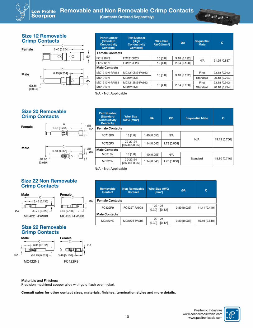
Removable and Non Removable Crimp Contacts(Contacts Ordered Separately)
Part Number (Standard
Conductivity Contacts)
Wire Size AWG [mm²] ØA ØB Sequential Mate C
Female Contacts
FC718P3 18 [1.0] 1.40 [0.055] N/AN/A 19.19 [0.756]
FC720P3 20-22-24[0.5-0.3-0.25] 1.14 [0.045] 1.73 [0.068]
Male ContactsMC718N 18 [1.0] 1.40 [0.055] N/A
Standard 18.80 [0.740]MC720N 20-22-24
[0.5-0.3-0.25] 1.14 [0.045] 1.73 [0.068]
RemovableContact
Non RemovableContact
Wire Size AWG [mm²] ØA C
Female Contacts
FC422P9 FC422T-PA90822 - 26
[0.30] - [0.12]0.89 [0.035] 11.41 [0.449]
Male Contacts
MC422N9 MC422T-PA90822 - 26
[0.30] - [0.12]0.89 [0.035] 15.49 [0.610]
Female
Female
Male
Male
Size 22 Non RemovableCrimp Contacts
Size 22 RemovableCrimp Contacts
Part Number (Standard
Conductivity Contacts)
Part Number(High
ConductivityContacts)
Wire Size AWG [mm²] ØA Sequential
Mate C
Female Contacts
FC1210P2 FC1210P2S 10 [6.0] 3.10 [0.122]N/A 21.25 [0.837]
FC1212P2 FC1212P2S 12 [4.0] 2.54 [0.100]
Male Contacts
MC1210N-PA563 MC1210NS-PA56310 [6.0] 3.10 [0.122]
First 23.18 [0.912]
MC1210N MC1210NS Standard 20.18 [0.794]
MC1212N-PA563 MC1212NS-PA56312 [4.0] 2.54 [0.100]
First 23.18 [0.912]
MC1212N MC1212NS Standard 20.18 [0.794]
Female
Male
Size 20 RemovableCrimp Contacts
Female
Male
Size 12 RemovableCrimp Contacts
N/A - Not Applicable
N/A - Not Applicable
Materials and Finishes: Precision machined copper alloy with gold flash over nickel.
Consult sales for other contact sizes, materials, finishes, termination styles and more details.
10
ØA
6.45 [0.254]C
ØA
6.45 [0.254]C
Ø2.38 [0.094]
6.48 [0.255]ØB
ØA
C
ØBØA6.48 [0.255]
Ø1.00[0.039]
C
Ø0.75 [0.029]ØA
C3.46 [0.136]
C
3.46 [0.136]
ØA
ØA Ø0.75 [0.029]
C3.35 [0.132]
C
3.46 [0.136]
ØA
MC422T-PA908
MC422N9
MC422T-PA908
FC422P9

Positronic Industrieswww.connectpositronic.comwww.positronicasia.com
Low Profile Scorpion
Recommended Tools for Crimp Contacts
Contact Extraction Tool Contact Insertion Tool Cycle-Controlled StepAdjustable Hand Crimp Tool
Contact Size
Contact Extraction Tool
Contact Insertion Tool Hand Crimp Tool
Size 12 2711-0-0 9099-3-09509-6-1 with 9509-6-2 positioner (*C1210** contacts)9501-0 with 9502-38-0 positioner (MC1212** contacts)9501-0 with 9502-37-0 positioner (FC1212** contacts)
Size 20 9081-2-0 9099-4-09507-0 with 9502-21 positioner (male contacts)9507-0 with 9502-22 positioner (female contacts)
Size 22 ^ 9081-3-0 9099-7-09507-0 with 9502-12-0 positioner (male contacts)9507-0 with 9502-13-0 positioner (female contacts)
^ Not Applicable for Size 22 non-removable crimp contacts.Consult sales for additional crimping tools and crimping information.
11
Recommended Tools for Crimp Contacts
• Sixpowercontactoptions:20ampversions through 85 amp.• Highdensitysignallines.• Shieldedcontactsandhighvoltageoptions.• Blindmating,floatmount,panelmountand cable connector options with unique locking system.• PCmount,crimp,andpressfitterminations.• Ventilationoptiontoincreaseaircooling.• Blankmodulestoincreasevoltageperformance.
BlindMatingGuide
Systems
14.60
Please refer to Scorpion Series Catalog No. A-010. Rev B for additional informations
50 Amp Power
Contacts Modules
30 Amp Power
Contacts Modules
Size 22Signal
Contact Modules
85 Amp Power
Contacts Modules
Size 1820 Amp
Contacts
JackscrewOption
BlankModules
for VoltageConsiderations
HighDensity
Signal Contact Modules
UniqueLockingSystems
SCORPION MODULAR CONNECTORS Complete Connector Customization - Quick and Affordable
3
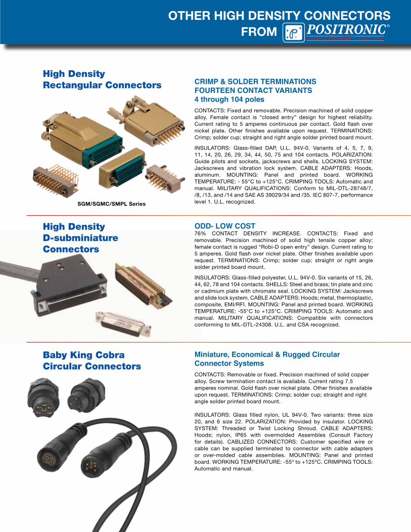
OTHER HIGH DENSITY CONNECTORS
CRIMP & SOLDER TERMINATIONSFOURTEEN CONTACT VARIANTS4 through 104 poles CONTACTS: Fixed and removable. Precision machined of solid copper alloy. Female contact is “closed entry” design for highest reliability. Current rating to 5 amperes continuous per contact. Gold flash over nickel plate. Other finishes available upon request. TERMINATIONS: Crimp; solder cup; straight and right angle solder printed board mount.
INSULATORS: Glass-filled DAP, U.L. 94V-0. Variants of 4, 5, 7, 9, 11, 14, 20, 26, 29, 34, 44, 50, 75 and 104 contacts. POLARIZATION: Guide pilots and sockets, jackscrews and shells. LOCKING SYSTEM: Jackscrews and vibration lock system. CABLE ADAPTERS: Hoods, aluminum. MOUNTING: Panel and printed board. WORKING TEMPERATURE: - 55°C to +125°C. CRIMPING TOOLS: Automatic and manual. MILITARY QUALIFICATIONS: Conform to MIL-DTL-28748/7, /8, /13, and /14 and SAE AS 39029/34 and /35. IEC 807-7, performance level 1. U.L. recognized.
ODD- LOW COST76% CONTACT DENSITY INCREASE. CONTACTS: Fixed and removable. Precision machined of solid high tensile copper alloy; female contact is rugged “Robi-D open entry” design. Current rating to 5 amperes. Gold flash over nickel plate. Other finishes available upon request. TERMINATIONS: Crimp; solder cup; straight or right angle solder printed board mount.
INSULATORS: Glass-filled polyester, U.L. 94V-0. Six variants of 15, 26, 44, 62, 78 and 104 contacts. SHELLS: Steel and brass; tin plate and zinc or cadmium plate with chromate seal. LOCKING SYSTEM: Jackscrews and slide lock system. CABLE ADAPTERS: Hoods; metal, thermoplastic, composite, EMI/RFI. MOUNTING: Panel and printed board. WORKING TEMPERATURE: -55°C to +125°C. CRIMPING TOOLS: Automatic and manual. MILITARY QUALIFICATIONS: Compatible with connectors conforming to MIL-DTL-24308. U.L. and CSA recognized.
Miniature, Economical & Rugged Circular Connector SystemsCONTACTS: Removable or fixed. Precision machined of solid copper alloy. Screw termination contact is available. Current rating 7.5 amperes nominal. Gold flash over nickel plate. Other finishes available upon request. TERMINATIONS: Crimp; solder cup; straight and right angle solder printed board mount.
INSULATORS: Glass filled nylon, UL 94V-0. Two variants: three size 20, and 6 size 22. POLARIZATION: Provided by insulator. LOCKING SYSTEM: Threaded or Twist Locking Shroud. CABLE ADAPTERS: Hoods; nylon, IP65 with overmolded Assembles (Consult Factory for details). CABLIZED CONNECTORS: Customer specified wire or cable can be supplied terminated to connector with cable adapters or over-molded cable assemblies. MOUNTING: Panel and printed board. WORKING TEMPERATURE: -55º to +125ºC. CRIMPING TOOLS: Automatic and manual.
High Density Rectangular Connectors
Baby King Cobra Circular Connectors
FROM
High DensityD-subminiature Connectors
SGM/SGMC/SMPL Series
®
NORTH AMERICAN SALES OFFICESUnited States, Springfield, MissouriFactory and Sales Office 800 641 4054 [email protected] Rico Sales Office 800 641 4054 [email protected] Sales Office 800 872 7674 [email protected] Sales Office 800 327 8272 [email protected]
EUROPEAN SALES OFFICESFrance, Auch Factory and Sales 33 (0) 5 6263 4491 [email protected] France Sales Office 33 (0) 1 4588 1388 [email protected] France Sales Office 33 (0) 6 8648 4023 [email protected] Sales Office 39 (0) 2 5411 6106 [email protected] Sales Office 49 (0) 23 5163 4739 [email protected] Kingdom Sales Office 44 (0) 7975 682 488 [email protected]
Europe & Middle East Technical Agents:Finland, United Kingdom, Scotland, Israel, Norway, Sweden, Turkey and the Ukraine.
ASIA/PACIFIC LOCATIONSSINGAPORE, Asia/Pacific Headquarters Factory Sales and Engineering Offices +65 6842 1419 [email protected]
ASIA, Direct Sales OfficesChina Factory - Zhuhai +86 756 3626 466 [email protected] Shenzhen +86 158 2907 9779 [email protected] Shanghai +86 158 2907 9779 [email protected] Xian Sales Office +86 029 8839 5306 [email protected] Beijing Sales Office +86 10 8203 7718 [email protected] Sales and Engineering Offices +81 3 6310 5830 [email protected]
India Factory Sales and Engineering Offices +91 20 2469 9910 [email protected] Bangalore Sales Office +91 94 4907 3251 [email protected] New Delhi Sales Office +91 80107 11175 [email protected]
Korea Sales Office +82 31 909 8047 [email protected] Sales Office +886 2 2937 8775 [email protected]
ASIA/PACIFIC, Technical AgentsTechnical Agents in Australia, Hong Kong, Malaysia, New Zealand, Philippines, Thailand and Vietnam.
POSITRONIC INDUSTRIES, INC423 N Campbell Avenue, P O Box 8247, Springfield, MO 65801, USATelephone: 1 417 866 2322Fax: 1 417 866 4115Email: [email protected]
POSITRONIC INDUSTRIES, SASZone Industrielle Est, 46 Route d’Engachies, F32020, Auch Cedex 9, FranceTelephone: 33 (0) 5 62 63 44 91Telecopieur: 33 (0) 5 62 63 51 17Email: [email protected]
POSITRONIC ASIA PTE LTD3014A Ubi Road 1 # 07-01 Singapore 408703Telephone: 65 6842 1419 Fax: 65 6842 1421
Email: [email protected]
www.connectpositronic.com
LO
W P
RO
FIL
E S
CO
RP
ION
Slim
Mod
ula
r P
ow
er
& S
ign
al C
on
tact
Con
necto
rs
®
Related Documents