REVIEW Open Access Low emission engine technologies for future tier 3 legislations - options and case studies Christer Wik * and Seppo Niemi * Correspondence: christer.wik@ wartsila.com University of Vaasa, Vaasa, Finland Abstract Marine emission legislation such as the current IMO Tier II and upcoming IMO Tier III requirements within the revised Marpol Annex VI have been major drivers for performance development of marine engines during the latest years. These requirements have triggered a vast amount of research activity at the engine OEM’s in order to identify and develop the best possible technologies for fulfilling the requirements. A main objective of this research has been to identify the various options available for reducing engine SOx and NOx emissions and to clarify the main criteria engine manufacturers consider to determine the optimum technology. Another objective has been to investigate how ship-owners and operators within the various marine segments are impacted by the new emissions requirements and what key factors they need to consider when identifying the optimum engine technology. Case studies conclude that the optimum solution can vary depending on the vessel application, operating time inside ECAs, as well as prices for fuels and reduction agents. In new-building cases, gas operated engines without after-treatment systems show a strong value proposition as an alternative to liquid fuel engines that require after-treatment solutions - especially for short-haul shipping applications where tighter emission legislations are enforced to a larger extent. Overall, 2-stage turbo charging, LNG, and SCR technologies are concluded to be the most feasible technologies. Generally, lower operating costs can compensate higher capital expenditures meaning that the owner should carefully evaluate the total cost of ownership of the various alternatives, and not consider only the initial capital expenditure. The choice of best technology option depends on a variety of issues which can change over time - such as the operation profile and route of the vessel and commodity prices. Consequently the ship-owner should evaluate the alternative technologies for a wide range of possible scenarios to find a flexible solution that minimizes exposure to risks related to changing boundary conditions. With this research, the reasons why certain emission reduction technologies are preferred to others both from OEM’s and ship-owner’s point of view are quantified and the most feasible technologies for meeting the requirements are identified. Keywords: Combustion engines, Emissions, Emission control areas, Emission technologies Journal of Shipping and Trade © 2016 The Author(s). Open Access This article is distributed under the terms of the Creative Commons Attribution 4.0 International License (http://creativecommons.org/licenses/by/4.0/), which permits unrestricted use, distribution, and reproduction in any medium, provided you give appropriate credit to the original author(s) and the source, provide a link to the Creative Commons license, and indicate if changes were made. Wik and Niemi Journal of Shipping and Trade (2016) 1:3 DOI 10.1186/s41072-016-0009-z

Welcome message from author
This document is posted to help you gain knowledge. Please leave a comment to let me know what you think about it! Share it to your friends and learn new things together.
Transcript
Journal of Shipping and Trade
Wik and Niemi Journal of Shipping and Trade (2016) 1:3 DOI 10.1186/s41072-016-0009-z
REVIEW Open Access
Low emission engine technologies forfuture tier 3 legislations - options and casestudies
Christer Wik* and Seppo Niemi* Correspondence: [email protected] of Vaasa, Vaasa, Finland
©Lpi
Abstract
Marine emission legislation such as the current IMO Tier II and upcoming IMO Tier IIIrequirements within the revised Marpol Annex VI have been major drivers forperformance development of marine engines during the latest years. Theserequirements have triggered a vast amount of research activity at the engine OEM’sin order to identify and develop the best possible technologies for fulfilling therequirements. A main objective of this research has been to identify the variousoptions available for reducing engine SOx and NOx emissions and to clarify the maincriteria engine manufacturers consider to determine the optimum technology.Another objective has been to investigate how ship-owners and operators within thevarious marine segments are impacted by the new emissions requirements and whatkey factors they need to consider when identifying the optimum engine technology.Case studies conclude that the optimum solution can vary depending on the vesselapplication, operating time inside ECAs, as well as prices for fuels and reductionagents. In new-building cases, gas operated engines without after-treatment systemsshow a strong value proposition as an alternative to liquid fuel engines that requireafter-treatment solutions - especially for short-haul shipping applications wheretighter emission legislations are enforced to a larger extent.Overall, 2-stage turbo charging, LNG, and SCR technologies are concluded to be themost feasible technologies. Generally, lower operating costs can compensate highercapital expenditures meaning that the owner should carefully evaluate the total costof ownership of the various alternatives, and not consider only the initial capitalexpenditure. The choice of best technology option depends on a variety of issueswhich can change over time - such as the operation profile and route of the vesseland commodity prices. Consequently the ship-owner should evaluate the alternativetechnologies for a wide range of possible scenarios to find a flexible solution thatminimizes exposure to risks related to changing boundary conditions.With this research, the reasons why certain emission reduction technologies arepreferred to others both from OEM’s and ship-owner’s point of view are quantifiedand the most feasible technologies for meeting the requirements are identified.
Keywords: Combustion engines, Emissions, Emission control areas, Emissiontechnologies
2016 The Author(s). Open Access This article is distributed under the terms of the Creative Commons Attribution 4.0 Internationalicense (http://creativecommons.org/licenses/by/4.0/), which permits unrestricted use, distribution, and reproduction in any medium,rovided you give appropriate credit to the original author(s) and the source, provide a link to the Creative Commons license, andndicate if changes were made.
Wik and Niemi Journal of Shipping and Trade (2016) 1:3 Page 2 of 22
IntroductionUp-coming marine emission legislations, like for instance the IMO Tier II and III stan-
dards within the Revised Marpol Annex VI (2009), have been major drivers for perform-
ance development of current marine engines during the latest years. Whilst focus in the
past could be put on improving only the engine efficiency, more stringent legislations
coming into force have led to a shift in focus towards reduced emissions altogether, focus-
ing on all of nitrogen oxides (NOx), sulphur oxides (SOx) and carbon dioxides (CO2). In
addition to the IMO global standards there are also a wide range of local regulations exist-
ing for NOx emissions as seen in EU (2015); US EPA (2015); European Clean Marine
(2004). The low emission initiatives are mainly focused on the EU and US so far, but there
are expectations that for instance parts of Asia and Australia will follow as well.
All these emission legislations have triggered a vast amount of research activities at
the marine engine OEM’s in order to identify and develop the best possible technolo-
gies for fulfilling the requirements. Analysis of the different technology options avail-
able, their strengths and weaknesses in respect of fulfilling the demands as well as
regarding implications on lifecycle costs have been presented in earlier publications
(Wik, 2010 & Wik 2013). There are a large amount of different technology choices
existing and operating on gas seems to be one of the strongest options with which all
future legislations are fulfilled at a low lifecycle cost.
Application of a Miller cycle in the engine is combining low NOx emissions with a
high cycle efficiency. Since the potential of medium-speed engine applications with ex-
treme Miller cycles together with two-stage turbo charging was first reported by Wik
and Hallbäck (2007), a lot of continued investigations and applications have been pub-
lished. Investigations with utilization of 1D simulation codes exploring 2-stage TC sys-
tem applications on gas engines as well as diesel engines together with EGR have been
reported by for instance Christen and Brand (2013); Codan et al. (2010); Millo et al.
(2010); Wik et al. (2009), whilst test results from both laboratory and field tests have
been presented by Behr et al. (2013); Kurth et al. (2013); Laiminger et al. (2011); Raikio
et al. (2010); Ryser et al. (2010); Tinschmann et al. (2012) and Wik et al. (2012) just to
mention a few.
The experience of and implementation of 2-stage turbo charging systems on
medium-speed diesel and gas engines increases fast and new products fulfilling future
IMO Tier III emission limits on diesel engines without after treatment systems, utiliz-
ing EGR, like presented by Vervaeke et al. (2013) have emerged as well.
General issues regarding gas engine development and presentation of the whole gas
engine portfolio from one OEM, has been reported amongst others by Nylund (2004);
Nylund and Ott (2013); Portin (2010). The logical step to take for future products
would be to implement 2-stage turbo charging systems also on gas engines as done by
other OEM’s (Laiminger et al. 2011; Trapp et al. 2013. Test results from natural gas op-
erated engines in combination with high-pressure turbo charging and early intake valve
closure timings (Miller cycles) for evaluation of the technology potential on both spark-
and diesel-pilot ignited engine types were presented by Monnet et al. (2014) and in
2015 new gas engine products implementing 2-stage turbo charging systems were re-
leased from different OEM’s (MAN 2015; Wärtsilä2 2015).
“An immediate demand for LNG (liquefied natural gas) as fuel for container shipping in
eco-zones, such as North Europe or the United States, can be expected in the near future”
Wik and Niemi Journal of Shipping and Trade (2016) 1:3 Page 3 of 22
said Donche-Gay (2014) at the 2014 SMM Exhibition and Congress in Hamburg,
Germany. He is not the only one believing in the future success of LNG in all shipping
sectors. One market where LNG is already the prevailing shipping fuel is Norway, where
implementation of the Norwegian NOx fund, an Environmental Agreement on NOx be-
tween business organizations and the Ministry of the Environment, has led to a radical in-
crease in engines operating on natural gas as according to Hoibye (2011). Within the
offshore and ferry sectors almost all ships run on LNG in Norway and major market
players like DNV GL (2014) believe it will come for all markets and sectors.
A study has also been conducted by Tzannatos et al. (2014) about implication on fuel,
technical, and external (due to exhaust emissions) costs by changing over from liquid
to gaseous (LNG) fuel on all ferries within the Greece archipelago, showing a huge
overall gain mainly due to lower external costs by changing to LNG. Lloyd’s Register
(2014) shows in their study and interview of 22 ports, mainly located in the US and
European ECAs, that availability of LNG infrastructure is now the second most import-
ant driver for the ports after ship owners’ demand and “76 % of the ports believe that
LNG bunkering operations will commence at their port within 5 years”.
Decisions regarding usage of a fuel cannot be taken without a complete lifecycle as-
sessment as well as look upon the global warming potential. This has been studied a lot
and even though the potential of LNG usage in reducing NOx, SOx, and PM emissions
is acknowledged, there are challenges in total greenhouse gases (GHG) (Brynolf et al.
2014a; Lindstad et al. 2015; Thomson et al. 2015). Brynolf et al. (2014a, b) and Thom-
son et al. (2015) look at a total fuel-cycle analysis including the extraction, processing
and operation stages for Ro-Ro and container vessels as well as tug applications
respectively. Whilst LNG would exhibit a GHG benefit directly vs. high-sulphur fuel
operation and comparing to low-sulphur fuel operation show a climate benefit within
30 years in container ship applications with diesel-ignited gas engines, a benefit would
take longer for tug applications as well as with spark ignited gas engines (Thomson
et al. 2015). For the chosen Ro-Ro applications, the global warming potential would be
very close to the one of HFO when using LNG as fuel as well as the European electri-
city mix, being a lot dependent upon coal and natural gas, and due to this considerable
reductions would demand usage of liquefied bio gas (Brynolf et al. 2014a, b). Biggest
challenges for the gas engines is seen to be the methane slip (CH4) emissions influen-
cing the total GHG emissions radically due to thirty times stronger warming potential
for 100-year equivalent mass compared to CO2 (Brynolf et al. 2014a, b; Thomson et al.
2015). Lindstad et al. (2015) focus on the global warming impact (GWI) from engine
operations only but include impacts of all emission components as well as operation at
high and low power for general cargo ships operating between the two present ECAs
i.e. North America and Europe. The average GWI over 20- and 100-year horizons are
compared and due to the strong global cooling effect of NOx, SOx, and organic carbon
in the atmosphere, high-sulphur fuels show the best result and the authors suggest to
still allow usage of high-sulphur heavy fuel oils (HFO) on open seas (Lindstad et al.
2015). Overall it can be concluded that LNG is the fuel of the future at least in short
sea shipping and the main question is how to build up the infrastructure and make it
available for ships in ports.
The main target of this study is to give an overview of the different engine technology
options available for fulfilling future NOx and SOx regulations as well as to list down
Wik and Niemi Journal of Shipping and Trade (2016) 1:3 Page 4 of 22
criteria used from engine OEM perspective regarding the choices made. The second
target is to via case studies find out the most advantageous technologies on some se-
lected ship applications.
Past research in this area has been focused on automotive industry like the work by
Cucchi and Hublin (1989) and Van der Straaten (2000) or regarding influence on costs
and prices of short sea traffic as well as possible transportation system modal splits with
introduction of emission legislations, like the work by Notteboom et al. (2010) as well as
Kalli et al. (2010). With the emerging of ECAs, more studies have been conducted related
to emission modelling and possible modal shifts as well as investigations of alternatives
for certain markets (Panagakos et al. 2014; Holmgren et al. 2014; Chang et al. 2014). For
instance Panagakos et al. (2014) conclude that possible stricter ECA sulphur limits on the
Mediterranean Sea might lead to a modal shift towards the land route. Brynolf et al.
(2014a, b) made a life cycle assessment of different alternatives to fulfil ECA sulphur and
NOx tier III regulations concluding that neither of the alternatives showed any significant
impact on climate change compared to HFO operation. A lot of investigations have also
focused on influence of vessel speed reduction on emissions but since that is not a solu-
tion for NOx Tier III compliance it is not dealt with in this paper. What is anyhow of ut-
most relevance are economical comparisons of alternatives to fulfil the ECA legislations
and for instance implementation of a real option analysis regarding LNG investments for
a retrofit case showed a clear trade-off between low fuel prices and capital expenses
(Acciaro 2014). Another study including a multi-criteria approach based on the analytic
network process (ANP) shows how this tool could help operators select the most
optimum technical alternative (Schinas & Stefanakos 2014).
MethodsMethod used for the main target of the study, to give an overview of the different en-
gine technology options available for fulfilling future NOx and SOx regulations as well
as to list down criteria used from an engine OEM perspective regarding the choices
made, is based on both qualitative and quantitative means.
A qualitative analysis has been done of in-house OEM data which have been partly
quantitatively compared towards literature data found for competitor OEM’s.
Major research questions to get an answer to are:
� How do the engine manufacturers make the final choices of technologies?
� Is the final choice only depending on lifecycle cost or are there other aspects as well?
Major research means to get an answer to the questions include collection of emission
abatement technology options based on in-house data. The researcher’s company data-
base has also been utilized for collecting input to case studies regarding effects on engine
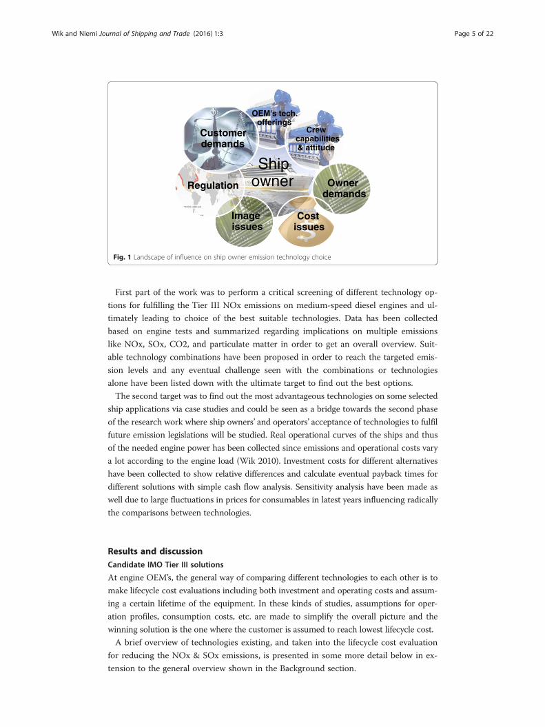
technology choice for different ship applications. Overall influence landscape on customer
emission technology choices could be seen in Fig. 1 and this paper’s research is related to
how important the following aspects are to the owner’s technology choices:
� OEM’s technology offerings
� Regulation
� Cost issues.
Ship owner
OEM's tech. offerings
Crew capabilities & attitude
Owner demands
Cost issues
Image issues
Regulation
Customer demands
Fig. 1 Landscape of influence on ship owner emission technology choice
Wik and Niemi Journal of Shipping and Trade (2016) 1:3 Page 5 of 22
First part of the work was to perform a critical screening of different technology op-
tions for fulfilling the Tier III NOx emissions on medium-speed diesel engines and ul-
timately leading to choice of the best suitable technologies. Data has been collected
based on engine tests and summarized regarding implications on multiple emissions
like NOx, SOx, CO2, and particulate matter in order to get an overall overview. Suit-
able technology combinations have been proposed in order to reach the targeted emis-
sion levels and any eventual challenge seen with the combinations or technologies
alone have been listed down with the ultimate target to find out the best options.
The second target was to find out the most advantageous technologies on some selected
ship applications via case studies and could be seen as a bridge towards the second phase
of the research work where ship owners’ and operators’ acceptance of technologies to fulfil
future emission legislations will be studied. Real operational curves of the ships and thus
of the needed engine power has been collected since emissions and operational costs vary
a lot according to the engine load (Wik 2010). Investment costs for different alternatives
have been collected to show relative differences and calculate eventual payback times for
different solutions with simple cash flow analysis. Sensitivity analysis have been made as
well due to large fluctuations in prices for consumables in latest years influencing radically
the comparisons between technologies.
Results and discussionCandidate IMO Tier III solutions
At engine OEM’s, the general way of comparing different technologies to each other is to
make lifecycle cost evaluations including both investment and operating costs and assum-
ing a certain lifetime of the equipment. In these kinds of studies, assumptions for oper-
ation profiles, consumption costs, etc. are made to simplify the overall picture and the
winning solution is the one where the customer is assumed to reach lowest lifecycle cost.
A brief overview of technologies existing, and taken into the lifecycle cost evaluation
for reducing the NOx & SOx emissions, is presented in some more detail below in ex-
tension to the general overview shown in the Background section.
Wik and Niemi Journal of Shipping and Trade (2016) 1:3 Page 6 of 22
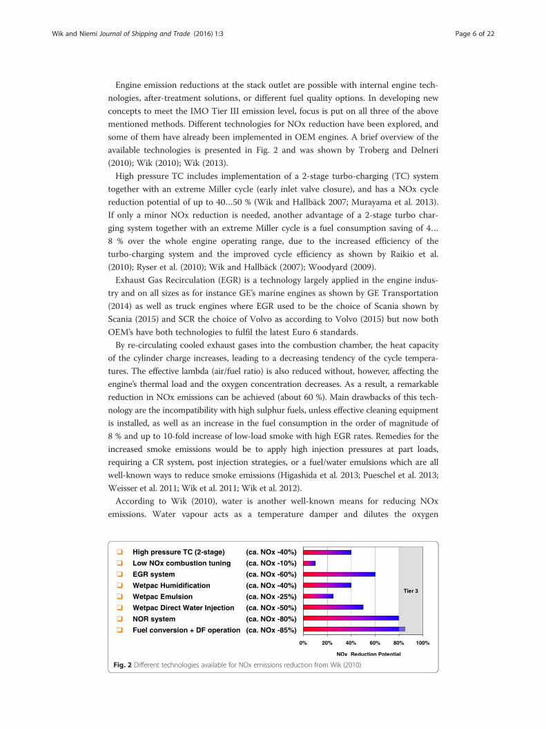
Engine emission reductions at the stack outlet are possible with internal engine tech-
nologies, after-treatment solutions, or different fuel quality options. In developing new
concepts to meet the IMO Tier III emission level, focus is put on all three of the above
mentioned methods. Different technologies for NOx reduction have been explored, and
some of them have already been implemented in OEM engines. A brief overview of the
available technologies is presented in Fig. 2 and was shown by Troberg and Delneri
(2010); Wik (2010); Wik (2013).
High pressure TC includes implementation of a 2-stage turbo-charging (TC) system
together with an extreme Miller cycle (early inlet valve closure), and has a NOx cycle
reduction potential of up to 40…50 % (Wik and Hallbäck 2007; Murayama et al. 2013).
If only a minor NOx reduction is needed, another advantage of a 2-stage turbo char-
ging system together with an extreme Miller cycle is a fuel consumption saving of 4…
8 % over the whole engine operating range, due to the increased efficiency of the
turbo-charging system and the improved cycle efficiency as shown by Raikio et al.
(2010); Ryser et al. (2010); Wik and Hallbäck (2007); Woodyard (2009).
Exhaust Gas Recirculation (EGR) is a technology largely applied in the engine indus-
try and on all sizes as for instance GE’s marine engines as shown by GE Transportation
(2014) as well as truck engines where EGR used to be the choice of Scania shown by
Scania (2015) and SCR the choice of Volvo as according to Volvo (2015) but now both
OEM’s have both technologies to fulfil the latest Euro 6 standards.
By re-circulating cooled exhaust gases into the combustion chamber, the heat capacity
of the cylinder charge increases, leading to a decreasing tendency of the cycle tempera-
tures. The effective lambda (air/fuel ratio) is also reduced without, however, affecting the
engine’s thermal load and the oxygen concentration decreases. As a result, a remarkable
reduction in NOx emissions can be achieved (about 60 %). Main drawbacks of this tech-
nology are the incompatibility with high sulphur fuels, unless effective cleaning equipment
is installed, as well as an increase in the fuel consumption in the order of magnitude of
8 % and up to 10-fold increase of low-load smoke with high EGR rates. Remedies for the
increased smoke emissions would be to apply high injection pressures at part loads,
requiring a CR system, post injection strategies, or a fuel/water emulsions which are all
well-known ways to reduce smoke emissions (Higashida et al. 2013; Pueschel et al. 2013;
Weisser et al. 2011; Wik et al. 2011; Wik et al. 2012).
According to Wik (2010), water is another well-known means for reducing NOx
emissions. Water vapour acts as a temperature damper and dilutes the oxygen
Fig. 2 Different technologies available for NOx emissions reduction from Wik (2010)
Wik and Niemi Journal of Shipping and Trade (2016) 1:3 Page 7 of 22
concentration in the combustion air, thus reducing the formation of NOx. If water is
directly injected into the combustion chamber it also has the effect of directly cooling
the combustion process (latent heat of evaporation). Different technologies have been
developed for water injection: inlet air humidification, water/fuel emulsions, and direct
water injection showing potential reductions in NOx of 25…50 %, and corresponding
increases in fuel consumption of 0.5…2 % (Wik 2010). Park et al. (2013) tested a com-
bination of EGR and inlet air humidification reaching IMO Tier III NOx with roughly
2 % increase in fuel consumption.
One of the biggest challenges with both EGR and Wetpac technologies is that NOx
reduction is lower at low loads, i.e. an increased EGR rate or water volume is needed at
low loads to reach the cycle average. Another challenge is the increased need for engine
flexibility, since NOx reduction is different at different loads and because fuel con-
sumption should always be minimized in the most important operating areas. Changes
in inlet valve timing (VIC) and fuel injection parameters (Common Rail or correspond-
ing system) are needed for this, and could be used to optimize the different load points
so that the 50 and 75 % load points are on the cycle limit value to get the best fuel con-
sumption, whilst the 25 % load point NOx is on the maximum accepted, i.e. 1.5*cycle
average, and the 100 % load point where SFOC is not important, should have NOx as
low as necessary to reach the cycle value.
Selective catalytic reduction (SCR) is one of the most effective ways to reduce NOx
emissions and all OEMs have reported activities with this technology since it is the
most straight forward way to reach IMO Tier III NOx compliance (see for example
Briggs & McCarney 2013; Hanamoto et al. 2013; Hiraoka & Imanaka 2013; Izumi et al.
2013; Murayama et al. 2013; Soikkeli et al. 2013; Steffe et al. 2013). Injected urea in the
exhaust pipe vaporizes and decomposes to form ammonia (NH3), which reacts on the
catalytic substrate thereby reducing the NOx to N2 by as much as 95 %. However, due
to cost and layout constraints, it is typically in the region of 80…85 %. The total hydro-
carbon (THC) and particulate matter emissions are also positively affected. The biggest
challenge seen with SCR operation is that exhaust gas temperatures of at least 330…
350 °C are needed with residual fuels having high sulphur content in order to avoid
clogging by the formation of ammonium sulphate. Alternatively, if the exhaust gas
temperature is too high, oxidizing of the SO2 to SO3 starts to happen in the SCR re-
actor, forming a so-called “blue haze”, which is visible as a blue exhaust gas plume. As
a result, some means of control, such as a waste gate or by-pass arrangement, is needed
with an SCR unit to keep the exhaust gas temperatures within a certain range. All en-
gine concepts developed for SCR applications would allow the best possible specific
fuel consumption, and in the case of utilising 2-stage TC systems, would give fuel con-
sumption savings of 4…8 % over the entire engine operating range.
Dual fuel (DF) engines able to run on both natural gas and heavy fuel oil (HFO)
represent one of the best options for the flexible handling of different emission limits
and is also under development by most of the engine OEMs. When operating as a lean
burn gas engine, the NOx emissions are about 85 % lower than in HFO operation. Fur-
thermore, sulphur oxide emissions are practically zero, since natural gas does not
normally contain any sulphur, while the CO2 emissions are about 30 % lower due to
the low carbon/hydrogen content of methane. As such, a DF engine would be IMO
Tier II compliant in HFO mode and Tier III compliant in gas mode.
Wik and Niemi Journal of Shipping and Trade (2016) 1:3 Page 8 of 22
The removal of sulphur oxide emissions can be achieved using either dry or wet
methods. Typical absorbents for a wet sulphur removal process are limestone, caustic
soda, seawater, ammonium hydroxide, or magnesium hydroxide, of which caustic soda
and seawater are the most feasible options for ship installations. Closed loop systems
can also be operated with zero discharge in enclosed areas. The other solutions offered
are either seawater scrubbers, needing no additional absorbent, or a hybrid scrubber
able to operate in both modes.
A common problem with after treatment equipment is that the back pressure in-
creases as more systems are installed in the exhaust pipe (SCR and scrubber) and this
leads to higher fuel consumption. A low temperature after the scrubber might also lead
to a coloured plume if not properly designed. Combination of SCR and scrubber units
have been tested and reported with good results in both SOx as well as NOx emission
reduction (Juergens 2013).
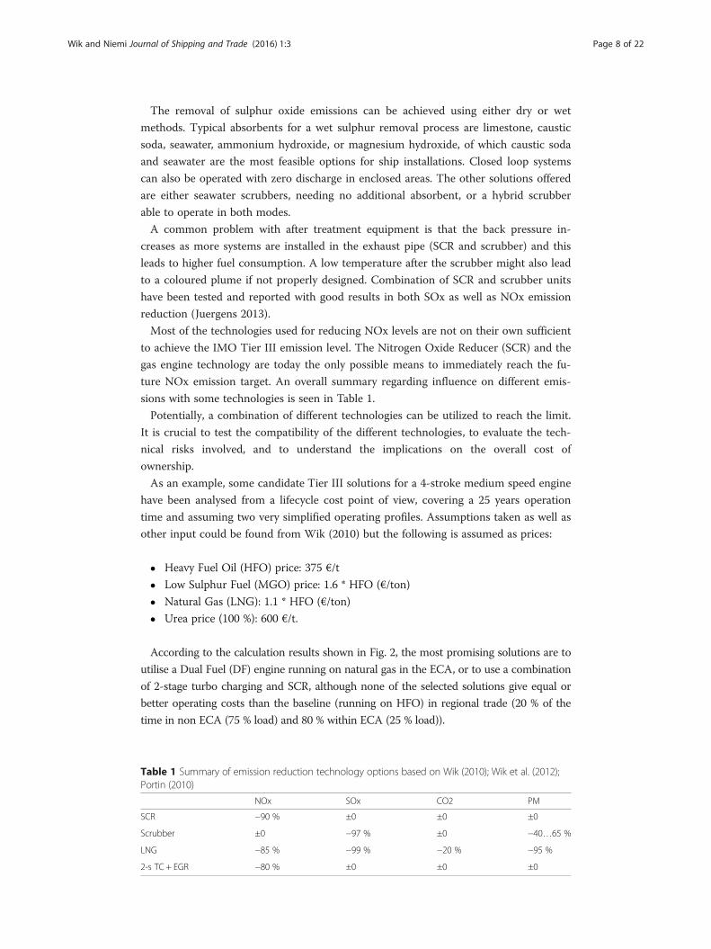
Most of the technologies used for reducing NOx levels are not on their own sufficient
to achieve the IMO Tier III emission level. The Nitrogen Oxide Reducer (SCR) and the
gas engine technology are today the only possible means to immediately reach the fu-
ture NOx emission target. An overall summary regarding influence on different emis-
sions with some technologies is seen in Table 1.
Potentially, a combination of different technologies can be utilized to reach the limit.
It is crucial to test the compatibility of the different technologies, to evaluate the tech-
nical risks involved, and to understand the implications on the overall cost of
ownership.
As an example, some candidate Tier III solutions for a 4-stroke medium speed engine
have been analysed from a lifecycle cost point of view, covering a 25 years operation
time and assuming two very simplified operating profiles. Assumptions taken as well as
other input could be found from Wik (2010) but the following is assumed as prices:
� Heavy Fuel Oil (HFO) price: 375 €/t
� Low Sulphur Fuel (MGO) price: 1.6 * HFO (€/ton)
� Natural Gas (LNG): 1.1 * HFO (€/ton)
� Urea price (100 %): 600 €/t.
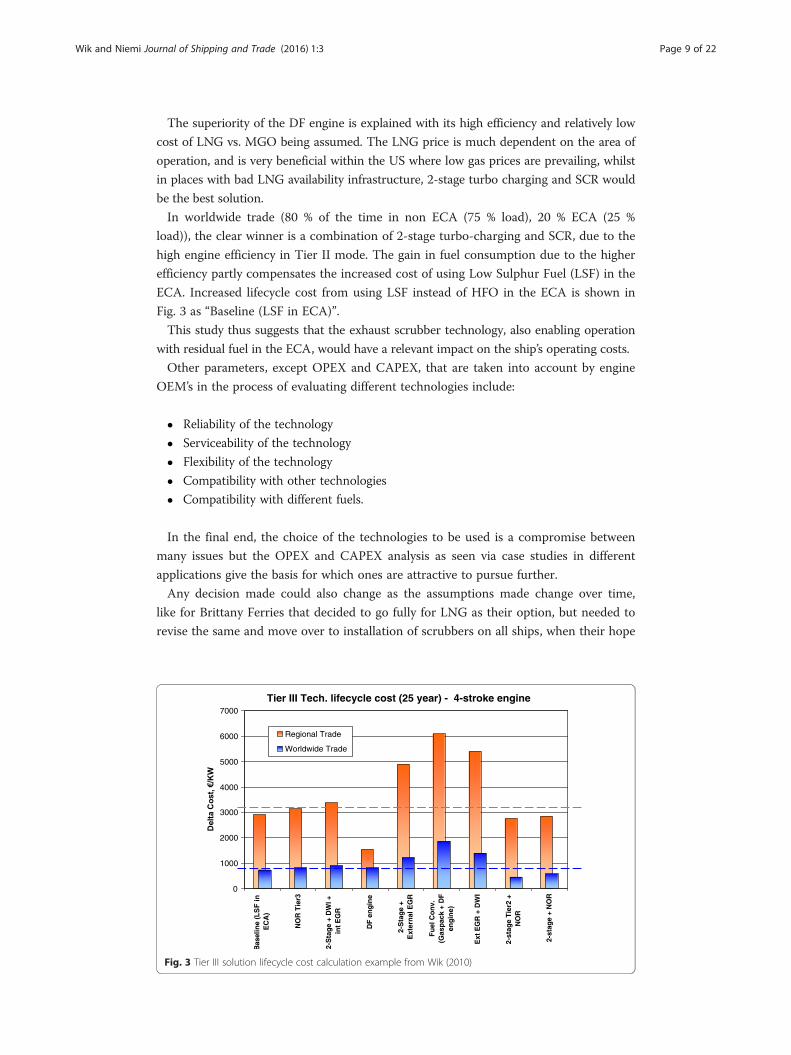
According to the calculation results shown in Fig. 2, the most promising solutions are to
utilise a Dual Fuel (DF) engine running on natural gas in the ECA, or to use a combination
of 2-stage turbo charging and SCR, although none of the selected solutions give equal or
better operating costs than the baseline (running on HFO) in regional trade (20 % of the
time in non ECA (75 % load) and 80 % within ECA (25 % load)).
Table 1 Summary of emission reduction technology options based on Wik (2010); Wik et al. (2012);Portin (2010)
NOx SOx CO2 PM
SCR −90 % ±0 ±0 ±0
Scrubber ±0 −97 % ±0 −40…65 %
LNG −85 % −99 % −20 % −95 %
2-s TC + EGR −80 % ±0 ±0 ±0
Wik and Niemi Journal of Shipping and Trade (2016) 1:3 Page 9 of 22
The superiority of the DF engine is explained with its high efficiency and relatively low
cost of LNG vs. MGO being assumed. The LNG price is much dependent on the area of
operation, and is very beneficial within the US where low gas prices are prevailing, whilst
in places with bad LNG availability infrastructure, 2-stage turbo charging and SCR would
be the best solution.
In worldwide trade (80 % of the time in non ECA (75 % load), 20 % ECA (25 %
load)), the clear winner is a combination of 2-stage turbo-charging and SCR, due to the
high engine efficiency in Tier II mode. The gain in fuel consumption due to the higher
efficiency partly compensates the increased cost of using Low Sulphur Fuel (LSF) in the
ECA. Increased lifecycle cost from using LSF instead of HFO in the ECA is shown in
Fig. 3 as “Baseline (LSF in ECA)”.
This study thus suggests that the exhaust scrubber technology, also enabling operation
with residual fuel in the ECA, would have a relevant impact on the ship’s operating costs.
Other parameters, except OPEX and CAPEX, that are taken into account by engine
OEM’s in the process of evaluating different technologies include:
� Reliability of the technology
� Serviceability of the technology
� Flexibility of the technology
� Compatibility with other technologies
� Compatibility with different fuels.
In the final end, the choice of the technologies to be used is a compromise between
many issues but the OPEX and CAPEX analysis as seen via case studies in different
applications give the basis for which ones are attractive to pursue further.
Any decision made could also change as the assumptions made change over time,
like for Brittany Ferries that decided to go fully for LNG as their option, but needed to
revise the same and move over to installation of scrubbers on all ships, when their hope
Tier III Tech. lifecycle cost (25 year) - 4-stroke engine
0
1000
2000
3000
4000
5000
6000
7000
EC
A)
NO
R T
ier3
2-S
tag
e +
DW
I +in
t E
GR
DF
en
gin
e
2-S
tag
e +
Ext
ern
al E
GR
Fu
el C
on
v.(G
asp
ack
+ D
Fen
gin
e)
Ext
EG
R +
DW
I
2-st
age
Tie
r2 +
NO
R
2-st
age
+ N
OR
Regional Trade
Worldwide Trade
Fig. 3 Tier III solution lifecycle cost calculation example from Wik (2010)
Wik and Niemi Journal of Shipping and Trade (2016) 1:3 Page 10 of 22
for dispensation to allow them to continue using low-sulphur residual fuels until the
new ships have arrived was not approved (Motorship 2015).
Case examples for Tier III compliant ships
A study has been carried out with examples of different ship types and with different
IMO Tier III technologies applied, to show the differences in installation, as well as the
eventual implications on the operating routes and profiles. The chosen cases were also
partly presented by Wik (2013) and include a Panamax tanker, cruise ship, platform
supply vessel (PSV), and a Ro-Ro/Pax vessel.
Case 1: panamax tanker
The first case presented is a Panamax tanker with a deadweight of 60 000 DWT and a
cargo capacity of 85 000 m3. According to statistics, based on a survey of approxi-
mately 50,000 vessels over a period of 45 days, tankers of this size operating in the
NAFTA region spend roughly 17 % of the time in ECAs and since the US ECA extends
200 nautical miles from the coasts of the United States and Canada territories, some
part of the operation will be at full speed.
Only half of the port time will be in an ECA since the other port will be in a country
from where oil is imported to the region, all being located outside of the North American
ECA. The U.S. oil import statistics by Terzic (2012) indicate that the top 5 countries, ac-
counting for 70 % of the imports, are as follows (in correct order): Canada, Saudi Arabia,
Mexico, Venezuela, Nigeria. Based on the studies regarding typical operating profiles and
annual cost structures for Panamax tankers, it is clear that a solution for the ECAs should
focus on achieving the best fuel efficiency. Thus, assuming price differences vs. HFO of
1.6 and 1.1 times price per ton for MGO and LNG respectively, avoidance of these fuels
would be preferable as according to Wik (2013).
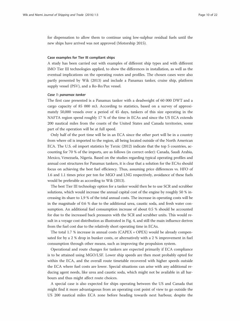
The best Tier III technology option for a tanker would then be to use SCR and scrubber
solutions, which would increase the annual capital cost of the engine by roughly 50 % in-
creasing its share to 1,9 % of the total annual costs. The increase in operating costs will be
in the magnitude of 0.6 % due to the additional urea, caustic soda, and fresh water con-
sumption. An additional fuel consumption increase of about 0.5 % should be accounted
for due to the increased back pressures with the SCR and scrubber units. This would re-
sult in a voyage cost distribution as illustrated in Fig. 4, and still the main influence derives
from the fuel cost due to the relatively short operating time in ECAs.
The total 1.7 % increase in annual costs (CAPEX +OPEX) would be already compen-
sated for by a 2 % drop in bunker costs, or alternatively with a 2 % improvement in fuel
consumption through other means, such as improving the propulsion system.
Operational and route changes for tankers are expected primarily if ECA compliance
is to be attained using MGO/LSF. Lower ship speeds are then most probably opted for
within the ECA, and the overall route timetable recovered with higher speeds outside
the ECA where fuel costs are lower. Special situations can arise with any additional re-
ducing agent needs, like urea and caustic soda, which might not be available in all har-
bours and thus might affect route choices.
A special case is also expected for ships operating between the US and Canada that
might find it more advantageous from an operating cost point of view to go outside the
US 200 nautical miles ECA zone before heading towards next harbour, despite the
Bunkers; 87,8
NaOH, urea & water cons.; 0,5
Port dues; 8,6 Canal tolls & misc.; 3,1
Fig. 4 Tanker voyage cost with SCR + scrubber
Wik and Niemi Journal of Shipping and Trade (2016) 1:3 Page 11 of 22
longer overall distance involved. This will most probably be the case for ships choosing
LSF for ECA compliance.
Case 2: cruise ship
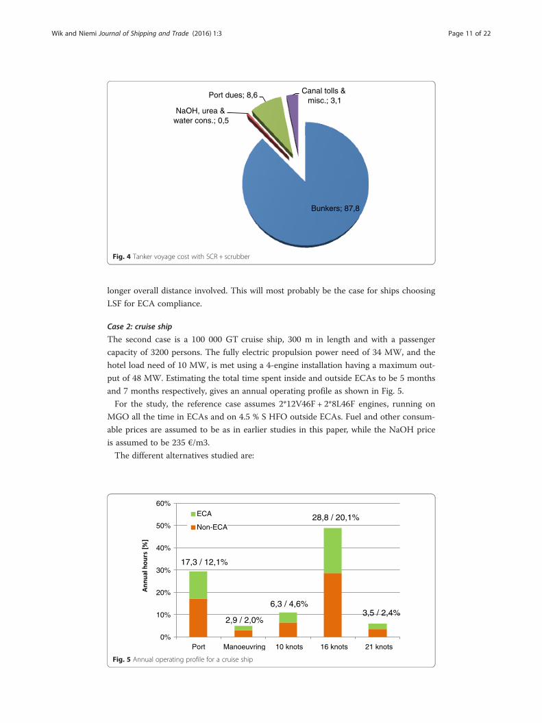
The second case is a 100 000 GT cruise ship, 300 m in length and with a passenger
capacity of 3200 persons. The fully electric propulsion power need of 34 MW, and the
hotel load need of 10 MW, is met using a 4-engine installation having a maximum out-
put of 48 MW. Estimating the total time spent inside and outside ECAs to be 5 months
and 7 months respectively, gives an annual operating profile as shown in Fig. 5.
For the study, the reference case assumes 2*12V46F + 2*8L46F engines, running on
MGO all the time in ECAs and on 4.5 % S HFO outside ECAs. Fuel and other consum-
able prices are assumed to be as in earlier studies in this paper, while the NaOH price
is assumed to be 235 €/m3.
The different alternatives studied are:
0%
10%
20%
30%
40%
50%
60%
Port Manoeuvring 10 knots 16 knots 21 knots
ECA
Non-ECA
17,3 / 12,1%
2,9 / 2,0%
6,3 / 4,6%
28,8 / 20,1%
3,5 / 2,4%
Fig. 5 Annual operating profile for a cruise ship
Wik and Niemi Journal of Shipping and Trade (2016) 1:3 Page 12 of 22
� The same engines running on HFO all the time except in the harbour where it runs
on MGO. SCR is in operation all the time in the ECA, while the scrubber reduces
the emitted SOx from the 4.5 % S HFO down to 3.5 % outside the ECA, and to
0.1 % inside the ECA
� The engines are replaced with 4*12V50DF running on LNG all the time
� In the case where a 2-stage TC system is installed for additional fuel savings, the
power output of the engine can be raised and 4 cylinders less are needed, thus the
engines are 2*12V46F + 2*6L46F.
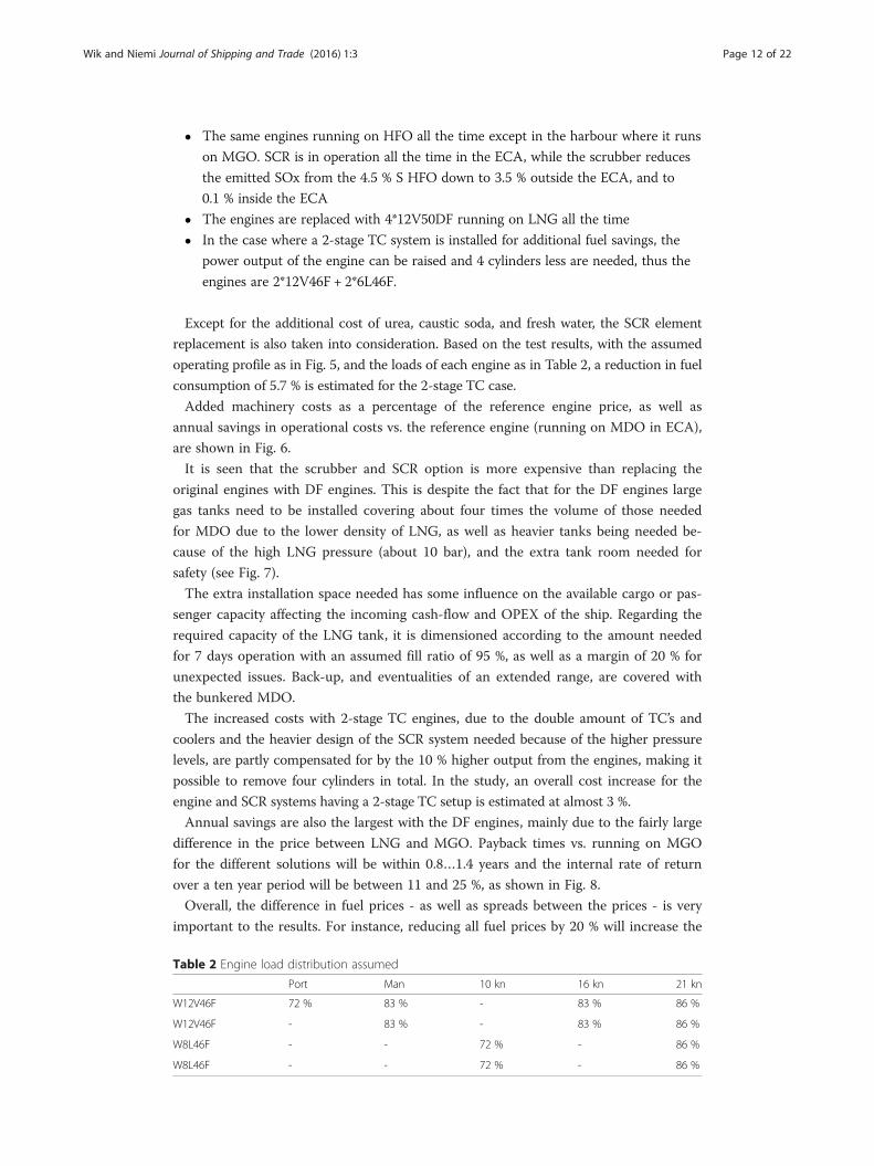
Except for the additional cost of urea, caustic soda, and fresh water, the SCR element
replacement is also taken into consideration. Based on the test results, with the assumed
operating profile as in Fig. 5, and the loads of each engine as in Table 2, a reduction in fuel
consumption of 5.7 % is estimated for the 2-stage TC case.
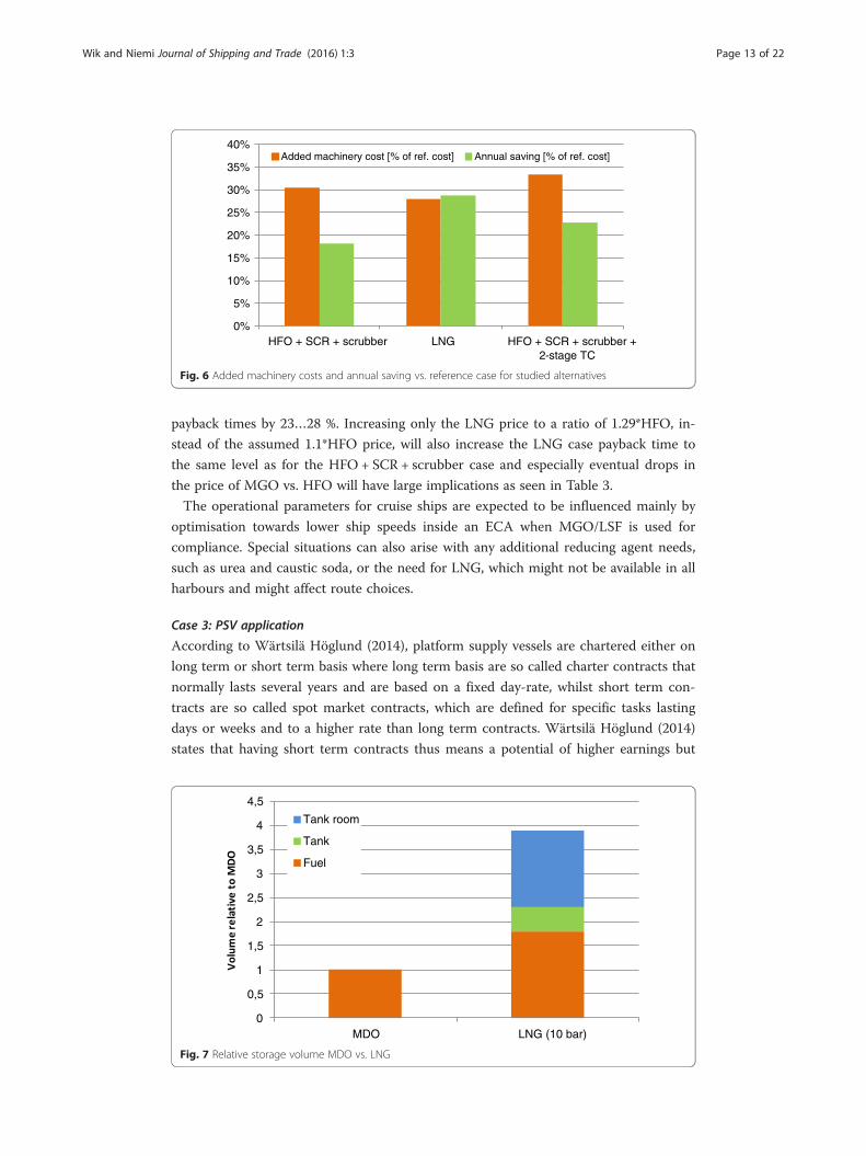
Added machinery costs as a percentage of the reference engine price, as well as
annual savings in operational costs vs. the reference engine (running on MDO in ECA),
are shown in Fig. 6.
It is seen that the scrubber and SCR option is more expensive than replacing the
original engines with DF engines. This is despite the fact that for the DF engines large
gas tanks need to be installed covering about four times the volume of those needed
for MDO due to the lower density of LNG, as well as heavier tanks being needed be-
cause of the high LNG pressure (about 10 bar), and the extra tank room needed for
safety (see Fig. 7).
The extra installation space needed has some influence on the available cargo or pas-
senger capacity affecting the incoming cash-flow and OPEX of the ship. Regarding the
required capacity of the LNG tank, it is dimensioned according to the amount needed
for 7 days operation with an assumed fill ratio of 95 %, as well as a margin of 20 % for
unexpected issues. Back-up, and eventualities of an extended range, are covered with
the bunkered MDO.
The increased costs with 2-stage TC engines, due to the double amount of TC’s and
coolers and the heavier design of the SCR system needed because of the higher pressure
levels, are partly compensated for by the 10 % higher output from the engines, making it
possible to remove four cylinders in total. In the study, an overall cost increase for the
engine and SCR systems having a 2-stage TC setup is estimated at almost 3 %.
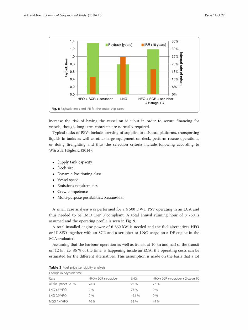
Annual savings are also the largest with the DF engines, mainly due to the fairly large
difference in the price between LNG and MGO. Payback times vs. running on MGO
for the different solutions will be within 0.8…1.4 years and the internal rate of return
over a ten year period will be between 11 and 25 %, as shown in Fig. 8.
Overall, the difference in fuel prices - as well as spreads between the prices - is very
important to the results. For instance, reducing all fuel prices by 20 % will increase the
Table 2 Engine load distribution assumed
Port Man 10 kn 16 kn 21 kn
W12V46F 72 % 83 % - 83 % 86 %
W12V46F - 83 % - 83 % 86 %
W8L46F - - 72 % - 86 %
W8L46F - - 72 % - 86 %
0%
5%
10%
15%
20%
25%
30%
35%
40%
HFO + SCR + scrubber LNG HFO + SCR + scrubber + 2-stage TC
Added machinery cost [% of ref. cost] Annual saving [% of ref. cost]
Fig. 6 Added machinery costs and annual saving vs. reference case for studied alternatives
Wik and Niemi Journal of Shipping and Trade (2016) 1:3 Page 13 of 22
payback times by 23…28 %. Increasing only the LNG price to a ratio of 1.29*HFO, in-
stead of the assumed 1.1*HFO price, will also increase the LNG case payback time to
the same level as for the HFO + SCR + scrubber case and especially eventual drops in
the price of MGO vs. HFO will have large implications as seen in Table 3.
The operational parameters for cruise ships are expected to be influenced mainly by
optimisation towards lower ship speeds inside an ECA when MGO/LSF is used for
compliance. Special situations can also arise with any additional reducing agent needs,
such as urea and caustic soda, or the need for LNG, which might not be available in all
harbours and might affect route choices.
Case 3: PSV application
According to Wärtsilä Höglund (2014), platform supply vessels are chartered either on
long term or short term basis where long term basis are so called charter contracts that
normally lasts several years and are based on a fixed day-rate, whilst short term con-
tracts are so called spot market contracts, which are defined for specific tasks lasting
days or weeks and to a higher rate than long term contracts. Wärtsilä Höglund (2014)
states that having short term contracts thus means a potential of higher earnings but
0
0,5
1
1,5
2
2,5
3
3,5
4
4,5
MDO LNG (10 bar)
Tank room
Tank
Fuel
Fig. 7 Relative storage volume MDO vs. LNG
0%
5%
10%
15%
20%
25%
30%
35%
0,0
0,2
0,4
0,6
0,8
1,0
1,2
1,4
HFO + SCR + scrubber LNG HFO + SCR + scrubber + 2-stage TC
Intern
al rate of retu
rn
Payback [years] IRR (10 years)
Fig. 8 Payback times and IRR for the cruise ship cases
Wik and Niemi Journal of Shipping and Trade (2016) 1:3 Page 14 of 22
increase the risk of having the vessel on idle but in order to secure financing for
vessels, though, long term contracts are normally required.
Typical tasks of PSVs include carrying of supplies to offshore platforms, transporting
liquids in tanks as well as other large equipment on deck, perform rescue operations,
or doing firefighting and thus the selection criteria include following according to
Wärtsilä Höglund (2014):
� Supply tank capacity
� Deck size
� Dynamic Positioning class
� Vessel speed
� Emissions requirements
� Crew competence
� Multi-purpose possibilities: Rescue/FiFi.
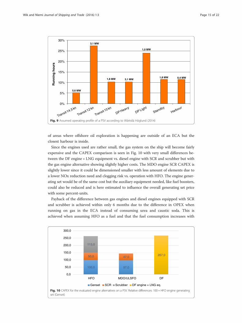
A small case analysis was performed for a 4 500 DWT PSV operating in an ECA and
thus needed to be IMO Tier 3 compliant. A total annual running hour of 8 760 is
assumed and the operating profile is seen in Fig. 9.
A total installed engine power of 6 660 kW is needed and the fuel alternatives HFO
or ULSFO together with an SCR and a scrubber or LNG usage on a DF engine in the
ECA evaluated.
Assuming that the harbour operation as well as transit at 10 kn and half of the transit
on 12 kn, i.e. 35 % of the time, is happening inside an ECA, the operating costs can be
estimated for the different alternatives. This assumption is made on the basis that a lot
Table 3 Fuel price sensitivity analysis
Change in payback time
Case HFO + SCR + scrubber LNG HFO + SCR + scrubber + 2-stage TC
All fuel prices -20 % 28 % 23 % 27 %
LNG 1.3*HFO 0 % 73 % 0 %
LNG 0,9*HFO 0 % −31 % 0 %
MGO 1.4*HFO 70 % 35 % 49 %
0%
5%
10%
15%
20%
25%
30%
Ru
nn
ing
ho
urs
5,6 MW
3,1 MW
1,8 MW 3,1 MW
1,0 MW
1,8 MW 0,4 MW
Fig. 9 Assumed operating profile of a PSV according to Wärtsilä Höglund (2014)
Wik and Niemi Journal of Shipping and Trade (2016) 1:3 Page 15 of 22
of areas where offshore oil exploration is happening are outside of an ECA but the
closest harbour is inside.
Since the engines used are rather small, the gas system on the ship will become fairly
expensive and the CAPEX comparison is seen in Fig. 10 with very small differences be-
tween the DF engine + LNG equipment vs. diesel engine with SCR and scrubber but with
the gas engine alternative showing slightly higher costs. The MDO engine SCR CAPEX is
slightly lower since it could be dimensioned smaller with less amount of elements due to
a lower NOx reduction need and clogging risk vs. operation with HFO. The engine gener-
ating set would be of the same cost but the auxiliary equipment needed, like fuel boosters,
could also be reduced and is here estimated to influence the overall generating set price
with some percent-units.
Payback of the difference between gas engines and diesel engines equipped with SCR
and scrubber is achieved within only 6 months due to the difference in OPEX when
running on gas in the ECA instead of consuming urea and caustic soda. This is
achieved when assuming HFO as a fuel and that the fuel consumption increases with
100,0 97,0
50,0 47,0
113,0
267,0
0,0
50,0
100,0
150,0
200,0
250,0
300,0
HFO MDO/ULSFO DF
Genset SCR Scrubber DF engine + LNG eq.
Fig. 10 CAPEX for the evaluated engine alternatives on a PSV. Relative differences: 100 = HFO engine generatingset (Genset)
Wik and Niemi Journal of Shipping and Trade (2016) 1:3 Page 16 of 22
0.5 % due to the higher back pressure with the SCR and scrubber in operation. Assum-
ing that low-sulphur MDO (ULSFO) is used instead, the payback would be about
3 years due to the avoidance of a scrubber investment for the diesel engine. Thus, the
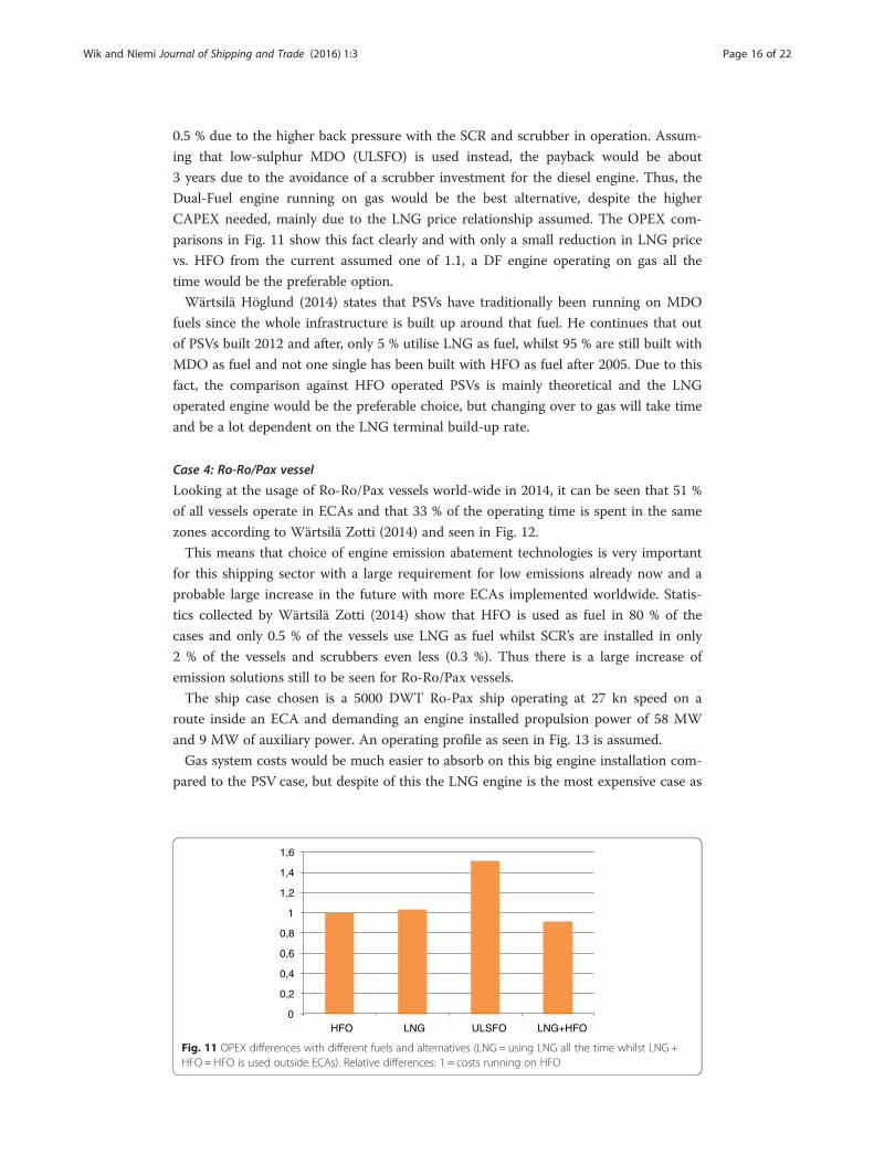
Dual-Fuel engine running on gas would be the best alternative, despite the higher
CAPEX needed, mainly due to the LNG price relationship assumed. The OPEX com-
parisons in Fig. 11 show this fact clearly and with only a small reduction in LNG price
vs. HFO from the current assumed one of 1.1, a DF engine operating on gas all the
time would be the preferable option.
Wärtsilä Höglund (2014) states that PSVs have traditionally been running on MDO
fuels since the whole infrastructure is built up around that fuel. He continues that out
of PSVs built 2012 and after, only 5 % utilise LNG as fuel, whilst 95 % are still built with
MDO as fuel and not one single has been built with HFO as fuel after 2005. Due to this
fact, the comparison against HFO operated PSVs is mainly theoretical and the LNG
operated engine would be the preferable choice, but changing over to gas will take time
and be a lot dependent on the LNG terminal build-up rate.
Case 4: Ro-Ro/Pax vessel
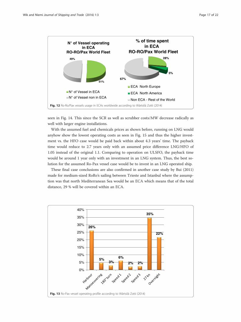
Looking at the usage of Ro-Ro/Pax vessels world-wide in 2014, it can be seen that 51 %
of all vessels operate in ECAs and that 33 % of the operating time is spent in the same
zones according to Wärtsilä Zotti (2014) and seen in Fig. 12.
This means that choice of engine emission abatement technologies is very important
for this shipping sector with a large requirement for low emissions already now and a
probable large increase in the future with more ECAs implemented worldwide. Statis-
tics collected by Wärtsilä Zotti (2014) show that HFO is used as fuel in 80 % of the
cases and only 0.5 % of the vessels use LNG as fuel whilst SCR’s are installed in only
2 % of the vessels and scrubbers even less (0.3 %). Thus there is a large increase of
emission solutions still to be seen for Ro-Ro/Pax vessels.
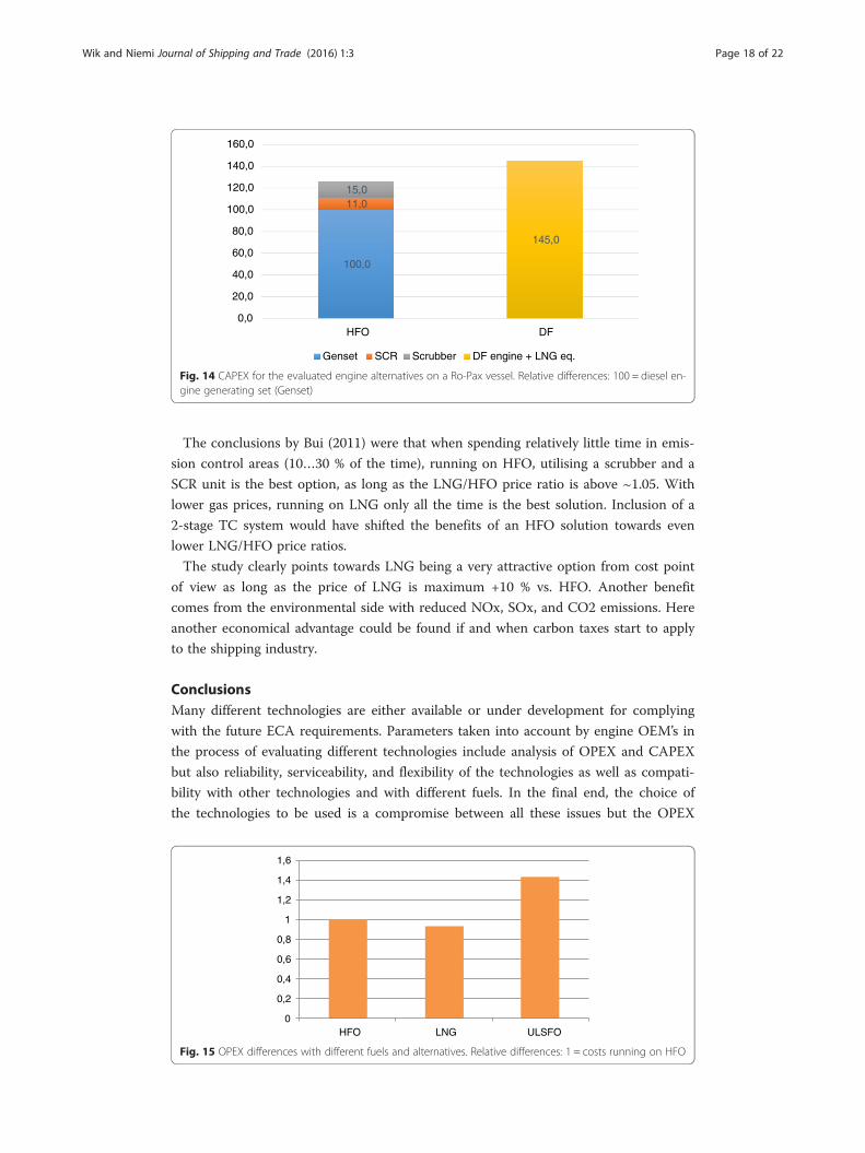
The ship case chosen is a 5000 DWT Ro-Pax ship operating at 27 kn speed on a
route inside an ECA and demanding an engine installed propulsion power of 58 MW
and 9 MW of auxiliary power. An operating profile as seen in Fig. 13 is assumed.
Gas system costs would be much easier to absorb on this big engine installation com-
pared to the PSV case, but despite of this the LNG engine is the most expensive case as
0
0,2
0,4
0,6
0,8
1
1,2
1,4
1,6
HFO LNG ULSFO LNG+HFO
Fig. 11 OPEX differences with different fuels and alternatives (LNG = using LNG all the time whilst LNG +HFO = HFO is used outside ECAs). Relative differences: 1 = costs running on HFO
28%
5%
67%
% of time spentin ECA
RO-RO/Pax World Fleet
ECA North America
Non ECA - Rest of the World
51%
49%
N° of Vessel operating in ECA
RO-RO/Pax World Fleet
N° of Vessel in ECA
N° of Vessel non in ECA
ECA North Europe
Fig. 12 Ro-Ro/Pax vessels usage in ECAs worldwide according to Wärtsilä Zotti (2014)
Wik and Niemi Journal of Shipping and Trade (2016) 1:3 Page 17 of 22
seen in Fig. 14. This since the SCR as well as scrubber costs/MW decrease radically as
well with larger engine installations.
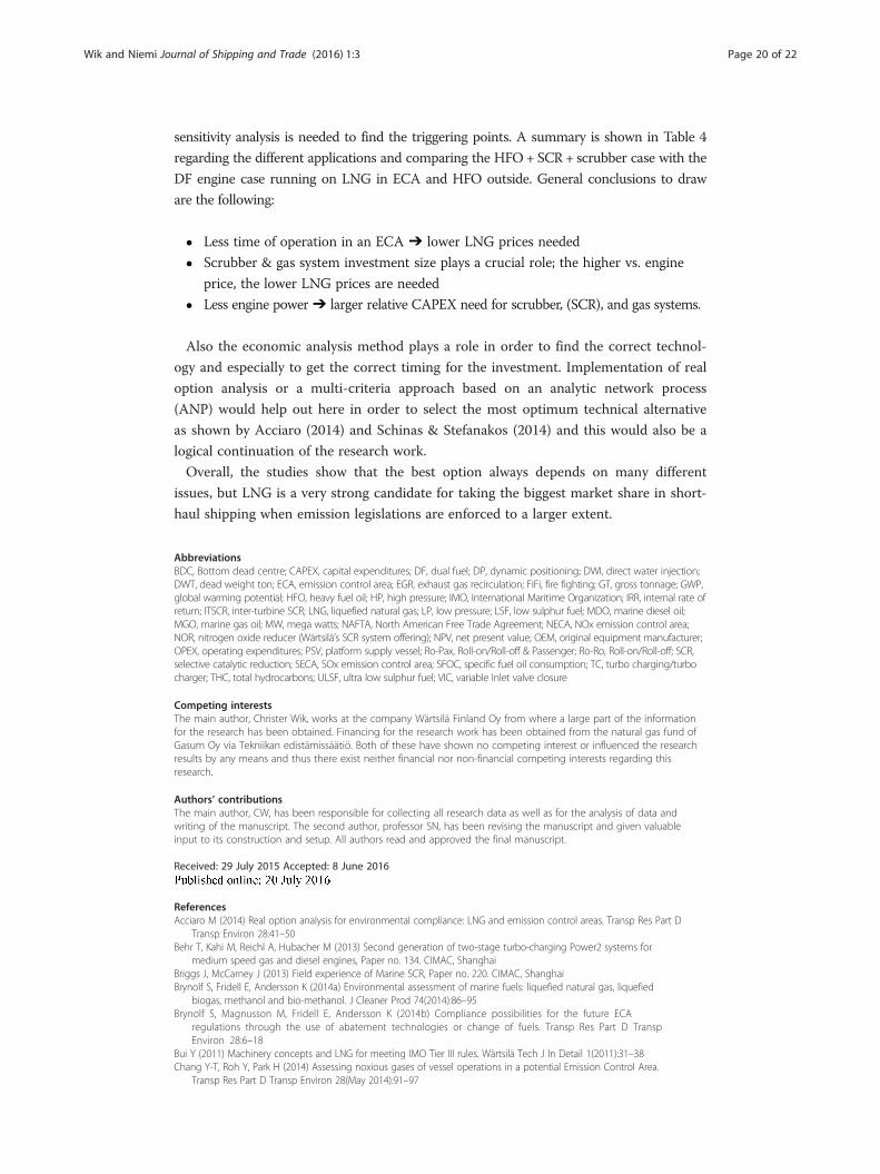
With the assumed fuel and chemicals prices as shown before, running on LNG would
anyhow show the lowest operating costs as seen in Fig. 15 and thus the higher invest-
ment vs. the HFO case would be paid back within about 4.3 years’ time. The payback
time would reduce to 2.7 years only with an assumed price difference LNG/HFO of
1.05 instead of the original 1.1. Comparing to operation on ULSFO, the payback time
would be around 1 year only with an investment in an LNG system. Thus, the best so-
lution for the assumed Ro-Pax vessel case would be to invest in an LNG operated ship.
These final case conclusions are also confirmed in another case study by Bui (2011)
made for medium-sized RoRo’s sailing between Trieste and Istanbul where the assump-
tion was that north Mediterranean Sea would be an ECA which means that of the total
distance, 29 % will be covered within an ECA.
26%
5%3%
6%
2% 2%
35%
22%
0%
5%
10%
15%
20%
25%
30%
35%
40%
Fig. 13 Ro-Pax vessel operating profile according to Wärtsilä Zotti (2014)
100,0
11,015,0
145,0
0,0
20,0
40,0
60,0
80,0
100,0
120,0
140,0
160,0
HFO DF
Genset SCR Scrubber DF engine + LNG eq.
Fig. 14 CAPEX for the evaluated engine alternatives on a Ro-Pax vessel. Relative differences: 100 = diesel en-gine generating set (Genset)
Wik and Niemi Journal of Shipping and Trade (2016) 1:3 Page 18 of 22
The conclusions by Bui (2011) were that when spending relatively little time in emis-
sion control areas (10…30 % of the time), running on HFO, utilising a scrubber and a
SCR unit is the best option, as long as the LNG/HFO price ratio is above ~1.05. With
lower gas prices, running on LNG only all the time is the best solution. Inclusion of a
2-stage TC system would have shifted the benefits of an HFO solution towards even
lower LNG/HFO price ratios.
The study clearly points towards LNG being a very attractive option from cost point
of view as long as the price of LNG is maximum +10 % vs. HFO. Another benefit
comes from the environmental side with reduced NOx, SOx, and CO2 emissions. Here
another economical advantage could be found if and when carbon taxes start to apply
to the shipping industry.
ConclusionsMany different technologies are either available or under development for complying
with the future ECA requirements. Parameters taken into account by engine OEM’s in
the process of evaluating different technologies include analysis of OPEX and CAPEX
but also reliability, serviceability, and flexibility of the technologies as well as compati-
bility with other technologies and with different fuels. In the final end, the choice of
the technologies to be used is a compromise between all these issues but the OPEX
0
0,2
0,4
0,6
0,8
1
1,2
1,4
1,6
HFO LNG ULSFO
Fig. 15 OPEX differences with different fuels and alternatives. Relative differences: 1 = costs running on HFO
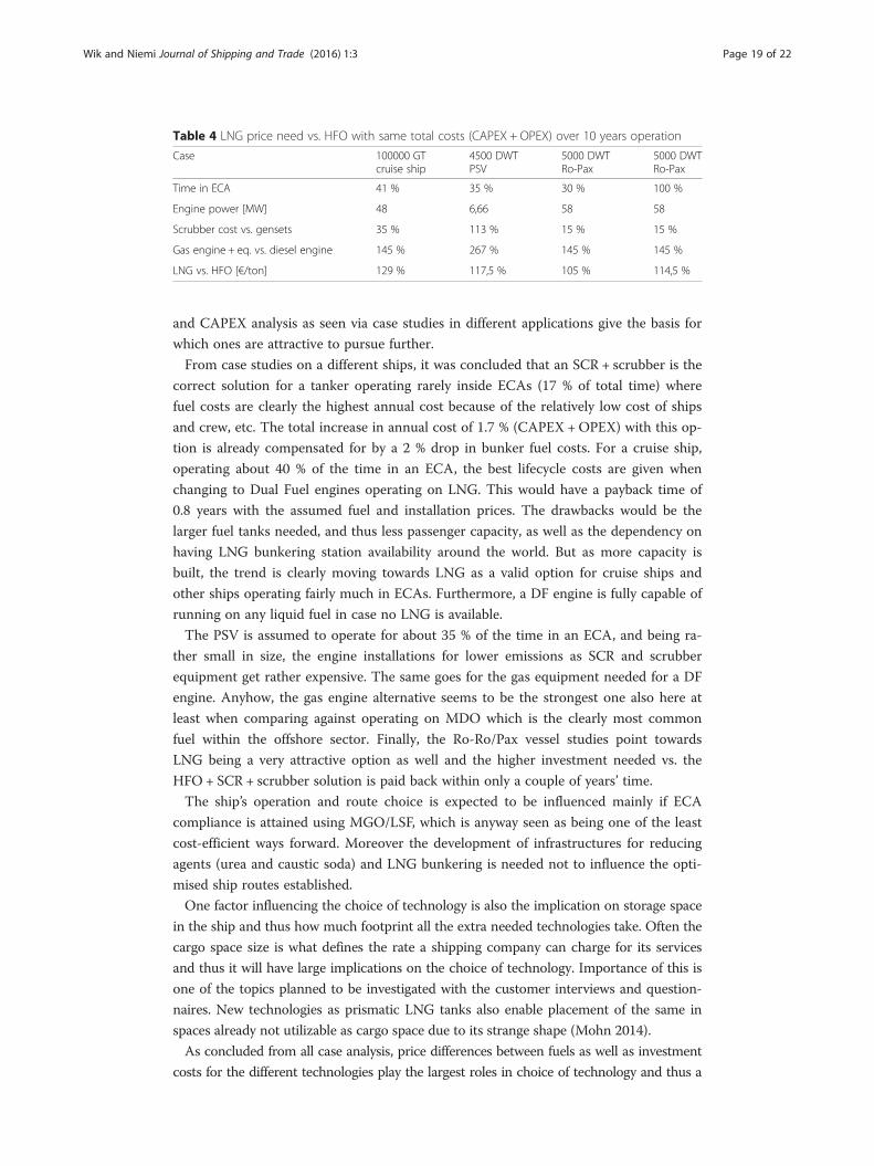
Table 4 LNG price need vs. HFO with same total costs (CAPEX + OPEX) over 10 years operation
Case 100000 GTcruise ship
4500 DWTPSV
5000 DWTRo-Pax
5000 DWTRo-Pax
Time in ECA 41 % 35 % 30 % 100 %
Engine power [MW] 48 6,66 58 58
Scrubber cost vs. gensets 35 % 113 % 15 % 15 %
Gas engine + eq. vs. diesel engine 145 % 267 % 145 % 145 %
LNG vs. HFO [€/ton] 129 % 117,5 % 105 % 114,5 %
Wik and Niemi Journal of Shipping and Trade (2016) 1:3 Page 19 of 22
and CAPEX analysis as seen via case studies in different applications give the basis for
which ones are attractive to pursue further.
From case studies on a different ships, it was concluded that an SCR + scrubber is the
correct solution for a tanker operating rarely inside ECAs (17 % of total time) where
fuel costs are clearly the highest annual cost because of the relatively low cost of ships
and crew, etc. The total increase in annual cost of 1.7 % (CAPEX +OPEX) with this op-
tion is already compensated for by a 2 % drop in bunker fuel costs. For a cruise ship,
operating about 40 % of the time in an ECA, the best lifecycle costs are given when
changing to Dual Fuel engines operating on LNG. This would have a payback time of
0.8 years with the assumed fuel and installation prices. The drawbacks would be the
larger fuel tanks needed, and thus less passenger capacity, as well as the dependency on
having LNG bunkering station availability around the world. But as more capacity is
built, the trend is clearly moving towards LNG as a valid option for cruise ships and
other ships operating fairly much in ECAs. Furthermore, a DF engine is fully capable of
running on any liquid fuel in case no LNG is available.
The PSV is assumed to operate for about 35 % of the time in an ECA, and being ra-
ther small in size, the engine installations for lower emissions as SCR and scrubber
equipment get rather expensive. The same goes for the gas equipment needed for a DF
engine. Anyhow, the gas engine alternative seems to be the strongest one also here at
least when comparing against operating on MDO which is the clearly most common
fuel within the offshore sector. Finally, the Ro-Ro/Pax vessel studies point towards
LNG being a very attractive option as well and the higher investment needed vs. the
HFO + SCR + scrubber solution is paid back within only a couple of years’ time.
The ship’s operation and route choice is expected to be influenced mainly if ECA
compliance is attained using MGO/LSF, which is anyway seen as being one of the least
cost-efficient ways forward. Moreover the development of infrastructures for reducing
agents (urea and caustic soda) and LNG bunkering is needed not to influence the opti-
mised ship routes established.
One factor influencing the choice of technology is also the implication on storage space
in the ship and thus how much footprint all the extra needed technologies take. Often the
cargo space size is what defines the rate a shipping company can charge for its services
and thus it will have large implications on the choice of technology. Importance of this is
one of the topics planned to be investigated with the customer interviews and question-
naires. New technologies as prismatic LNG tanks also enable placement of the same in
spaces already not utilizable as cargo space due to its strange shape (Mohn 2014).
As concluded from all case analysis, price differences between fuels as well as investment
costs for the different technologies play the largest roles in choice of technology and thus a
Wik and Niemi Journal of Shipping and Trade (2016) 1:3 Page 20 of 22
sensitivity analysis is needed to find the triggering points. A summary is shown in Table 4
regarding the different applications and comparing the HFO+ SCR + scrubber case with the
DF engine case running on LNG in ECA and HFO outside. General conclusions to draw
are the following:
� Less time of operation in an ECA ➔ lower LNG prices needed
� Scrubber & gas system investment size plays a crucial role; the higher vs. engine
price, the lower LNG prices are needed
� Less engine power➔ larger relative CAPEX need for scrubber, (SCR), and gas systems.
Also the economic analysis method plays a role in order to find the correct technol-
ogy and especially to get the correct timing for the investment. Implementation of real
option analysis or a multi-criteria approach based on an analytic network process
(ANP) would help out here in order to select the most optimum technical alternative
as shown by Acciaro (2014) and Schinas & Stefanakos (2014) and this would also be a
logical continuation of the research work.
Overall, the studies show that the best option always depends on many different
issues, but LNG is a very strong candidate for taking the biggest market share in short-
haul shipping when emission legislations are enforced to a larger extent.
AbbreviationsBDC, Bottom dead centre; CAPEX, capital expenditures; DF, dual fuel; DP, dynamic positioning; DWI, direct water injection;DWT, dead weight ton; ECA, emission control area; EGR, exhaust gas recirculation; FiFi, fire fighting; GT, gross tonnage; GWP,global warming potential; HFO, heavy fuel oil; HP, high pressure; IMO, International Maritime Organization; IRR, internal rate ofreturn; ITSCR, inter-turbine SCR; LNG, liquefied natural gas; LP, low pressure; LSF, low sulphur fuel; MDO, marine diesel oil;MGO, marine gas oil; MW, mega watts; NAFTA, North American Free Trade Agreement; NECA, NOx emission control area;NOR, nitrogen oxide reducer (Wärtsilä’s SCR system offering); NPV, net present value; OEM, original equipment manufacturer;OPEX, operating expenditures; PSV, platform supply vessel; Ro-Pax, Roll-on/Roll-off & Passenger; Ro-Ro, Roll-on/Roll-off; SCR,selective catalytic reduction; SECA, SOx emission control area; SFOC, specific fuel oil consumption; TC, turbo charging/turbocharger; THC, total hydrocarbons; ULSF, ultra low sulphur fuel; VIC, variable Inlet valve closure
Competing interestsThe main author, Christer Wik, works at the company Wärtsilä Finland Oy from where a large part of the informationfor the research has been obtained. Financing for the research work has been obtained from the natural gas fund ofGasum Oy via Tekniikan edistämissäätiö. Both of these have shown no competing interest or influenced the researchresults by any means and thus there exist neither financial nor non-financial competing interests regarding thisresearch.
Authors’ contributionsThe main author, CW, has been responsible for collecting all research data as well as for the analysis of data andwriting of the manuscript. The second author, professor SN, has been revising the manuscript and given valuableinput to its construction and setup. All authors read and approved the final manuscript.
Received: 29 July 2015 Accepted: 8 June 2016
References
Acciaro M (2014) Real option analysis for environmental compliance: LNG and emission control areas. Transp Res Part DTransp Environ 28:41–50Behr T, Kahi M, Reichl A, Hubacher M (2013) Second generation of two-stage turbo-charging Power2 systems for
medium speed gas and diesel engines, Paper no. 134. CIMAC, ShanghaiBriggs J, McCarney J (2013) Field experience of Marine SCR, Paper no. 220. CIMAC, ShanghaiBrynolf S, Fridell E, Andersson K (2014a) Environmental assessment of marine fuels: liquefied natural gas, liquefied
biogas, methanol and bio-methanol. J Cleaner Prod 74(2014):86–95Brynolf S, Magnusson M, Fridell E, Andersson K (2014b) Compliance possibilities for the future ECA
regulations through the use of abatement technologies or change of fuels. Transp Res Part D TranspEnviron 28:6–18
Bui Y (2011) Machinery concepts and LNG for meeting IMO Tier III rules. Wärtsilä Tech J In Detail 1(2011):31–38Chang Y-T, Roh Y, Park H (2014) Assessing noxious gases of vessel operations in a potential Emission Control Area.
Transp Res Part D Transp Environ 28(May 2014):91–97
Wik and Niemi Journal of Shipping and Trade (2016) 1:3 Page 21 of 22
Christen C, Brand D (2013) IMO tier 3: gas and dual fuel engines as a clean and efficient solution, Paper no. 187. CIMAC,Shanghai
Codan E et al (2010) Two-stage turbocharging – flexibility for engine optimization, Paper no.293. CIMAC, BergenCucchi C, Hublin M (1989) Evolution of emissions legislation in Europe and impact on technology, SAE paper no.
890487DNV GL (2014). ‘The Future of Shipping’, Høvik, 2014 http://futureshipping.dnvgl.com/#future-shipping)Donche-Gay P (2014) BV: LNG as fuel gaining momentum. speech at 2014 SMM Exhibition and Congress in Hamburg,
Germany (http://www.lngworldnews.com/bv-lng-as-fuel-gaining-momentum)EU (2015). EU Inland water vessels, https://www.dieselnet.com/standards/eu/nonroad.php #vesselEuropean Clean Marine Award (2004) Port of Stockholm, http://ec.europa.eu/environment/archives/clean_marine/pdf/
port_of_stockholm.pdfHanamoto K, Okauchi T, Sato K, Ogura S, Horikawa M, Asano J (2013) Development of new environmentally friendly
diesel engines 6DE-18 and 6DE-23, Paper no. 135. CIMAC, ShanghaiHigashida M, Nakamura T, Onishi I, Yoshizawa K, Takata H, Hosono T (2013) Newly developed combined EGR &
WEF system to comply with IMO NOx regulation tier 3 for two-stroke diesel engine, Paper no. 200. CIMAC,Shanghai
Hiraoka N, Imanaka K (2013) Exhaust emission control of Mitsubishi diesel engine, Paper no. 418. CIMAC, ShanghaiHoibye G (2011) Norwegian NOx Fund as an instrument to reduce emissions from ships. Brussels, June 1, 2011, http://
ec.europa.eu/transport/modes/maritime/events/doc/2011_06_01_stakeholder-event/item14_norway_business_sector_nox_fund.pdf)
Holmgren J, Nikopoulou Z, Ramstedt L, Woxenius J (2014) Modelling modal choice effects of regulation on low-sulphurmarine fuels in Northern Europe. Transp Res Part D Transp Environ 28:62–73
Izumi Y, Ohara H, Kamata H, Nakajima H, Yamada T, Irie M, Moriyama K, Goto K (2013) Urea-SCR system for pollutioncontrol in marine diesel engines, Paper no. 172. CIMAC, Shanghai
Juergens R (2013) First operational experiences with a combined dry desulphurization plant and SCR Unit downstreamof a HFO fuelled marine engine, Paper no. 5. CIMAC, Shanghai
Kalli J, Repka S, Karvonen T (2010) Baltic NECA – economic impacts, Study report by University of Turku, Centre forMaritime Studies, October 2010
Kurth D, Adorf S, Grabmaier A, Gruensteudel L, Kolb S, Offinger B (2013) MAN diesel & turbo product portfolio of dieselengines adapted to actual challenges, Paper no. 198. CIMAC, Shanghai
Laiminger S, Trapp C, Schaumberger H, Fouquet M (2011) Die nächste Generation von Jenbacher Gasmotoren von GE– die wegweisende Kombination von zweistufiger Aufladung und innovativen Brennverfahren. 7th Dessau GasEngine Conference, Dessau
Lindstad H, Eskeland GS, Psaraftis H, Sandaas I (2015) Maritime shipping and emissions: a three-layered, damage-basedapproach. Ocean Eng 110(2015):94–101
Lloyd’s Register (2014) Report indicates LNG bunkering is likely to develop fast as global ports get ready for shipping’sgas fuelled future. Lloyd’s Register, news 7 April 2014, http://www.lr.org/en/news/news/lng-bunker-report.aspx
MAN (2015) MAN diesel & turbo presents two staged gas engine range at power-gen Europe. MAN press release 29.4.2015, http://www.corporate.man.eu/en/press-and-media/presscenter/MAN-Diesel-and-Turbo-Presents-Two-Staged-Gas-Engine-Range-at-Power-Gen-Europe–203584.html
Millo F, Gianoglio M, Delneri D (2010) Combining dual stage turbocharging with extreme Miller timings to achieve NOxemissions reductions in marine diesel engines. 26th CIMAC Congress, Bergen
Mohn H (2014) The time to act is now. Baltic Transp J 6:26–27Monnet G, Hallbäck B, Isaksson S (2014) Two-stage turbo charging system application for medium-speed gas engines,
19th Supercharging Conference, p 35–48Motorship (2015) Brittany begins scrubber roll-out. Motorship March 2015, p 12Murayama Y, Tagai T, Mimura T, Goto S (2013) Demonstration of emission control technology for IMO NOx Tier III,
Paper no. 127. CIMAC, ShanghaiNotteboom T, Delhaye E, Vanherle K (2010) Analysis of the consequences of low sulphur fuel requirements’, report
commissioned by European Community Shipowners’ Associations (ECSA), 29.01.2010Nylund I (2004) Status and potentials of the gas engines, Paper no. 163. CIMAC, KyotoNylund I, Ott M (2013) Development of a Dual Fuel technology for slow-speed engines, Paper no. 284. CIMAC, ShanghaiPanagakos GP, Stamatopoulou EV, Psaraftis HN (2014) The possible designation of the Mediterranean Sea as a SECA: a
case study. Transp Res Part D Transp Environ 28:74–90Park H-K, Park J, Bae M, Ghal S-H, Choi K-H, Park H-C (2013) NOx reduction by combination of charge air moisturizer
and exhaust gas recirculation on medium speed diesel engines, Paper no. 133. CIMAC, ShanghaiPortin K (2010) Wärtsilä dual fuel (DF) engines for offshore applications and mechanical drive, Paper no. 112. CIMAC,
BergenPueschel M, Buchholz B, Fink C, Rickert C, Ruschmeyer K (2013) Combination of post-injection and cooled EGR at a
medium-speed diesel engine to comply with IMO Tier III emission limits, Paper no. 76. CIMAC, ShanghaiRaikio T, Hallbäck B, Hjort A (2010) Design and first application of a two-stage turbocharging system for a medium-
speed diesel engine, Paper no. 82. CIMAC, BergenRevised MARPOL Annex VI (2009) Regulations for the prevention of Air pollution from ships and NOX technical code
2008. International Maritime Organization, LondonRyser R, Weisser G, Wik C (2010) Application of 2-stage turbocharging to large diesel engines: Recent developments
and new perspectives, 15th Supercharging Conference, September 2010, p 27–43Scania (2015) Scania EGR, http://www.scania.com/products-services/trucks/main-components/engines/engine-
technology/egr/Schinas O, Stefanakos CN (2014) Selecting technologies towards compliance with MARPOL annex VI: the perspective of
operators. Transp Res Part D Transp Environ 28:28–40
Wik and Niemi Journal of Shipping and Trade (2016) 1:3 Page 22 of 22
Soikkeli N, Lehikoinen M, Ronnback K-O (2013) Design aspects of SCR systems for HFO fired marine diesel engines,Paper no. 179. CIMAC, Shanghai
Steffe P, Liepert K, Losher R, Bader I (2013) High performance solutions for IMO Tier III – system integration of engineand aftertreatment technologies as element of success, Paper no. 212. CIMAC, Shanghai
Terzic B (2012) Energy independence and security: a reality check, Deloitte University PressThomson H, Corbett JJ, Winebrake JJ (2015) Natural gas as a marine fuel. Energy Policy 87(2015):153–167Tinschmann G, Lang J, Thalhauser J, Klausner J, Amplatz E, Trapp C (2012) Gas engines with two stage turbocharging – field
experience, design opportunities for different applications, further development. Aufladetechnische Konferenz, Dresden, p 17GE Transportation (2014) GE Transportation delivers first EPA Tier 4 emissions-compliant marine diesel engines
featuring breakthrough technology. News release 04.12.2014, http://www.getransportation.com/news/ge-transportation-delivers-first-epa-tier-4-emissions-compliant-marine-diesel-engines-featuring
Trapp C, Birgel A, Spyra N, Kopecek H, Chvatal D (2013) GE’s all new J920 gas engine- a smart accretion of two-stageturbocharging, ultra lean combustion concept and intelligent controls, Paper no. 289. CIMAC, Shanghai
Troberg M, Delneri D (2010) Tier III emission roadmap for marine engine application, MTZ 06/2010, p 12–17Tzannatos E, Papadimitriou S, Koliousis SI (2014) A Techno-Economic Analysis of Oil vs Natural Gas Operation for Greek
Island Ferries. Int J Sustain Transport 9(5):272–281US EPA (2015) US EPA Diesel boats and ships, Regulations, http://www.epa.gov/otaq/marine.htmVan der Straaten Y (2000) Globalization of motor vehicle industry: history and trends from a market and technical
legislation point of view, SAE paper no. 2000-05-0005Vervaeke L, Berckmoes T, Verhelst S (2013) The CRISTAL engine: ABC’s new medium speed diesel engine, developed to
comply with IMO III, Paper no. 83. CIMAC, ShanghaiVolvo (2015) Volvo is ready for Euro 6. Here’s D13K460’, http://www.volvotrucks.com/trucks/global/en-gb/trucks/
environment/Pages/Euro6.aspxWärtsilä Höglund (2014) PSV 4-stroke value proposition. Wärtsilä internal presentation, Nico Höglund, 7.11.2014Wärtsilä Zotti (2014) Ro-Ro/Pax 4-stroke value proposition. Wärtsilä internal presentation, Andrea Zotti, 24.6.2014Wärtsilä2 (2015) Wärtsilä launches the new Wärtsilä 31 engine: a breakthrough in efficiency’ Wärtsilä Corporation Press
release 2.6.2015, http://www.wartsila.com/media/news/02-06-2015-wartsila-launches-the-new-wartsila-31-engine-a-breakthrough-in-efficiency
Weisser G, Wik C, Delneri D (2011) IMO tier III – challenging task for the developers of large diesel engines. 13. Tagung“DER ARBEITS-PROZESS DES VERBRENNUNGSMOTORS”, Graz
Wik C (2010) Reducing medium-speed engine emissions. J Marine Eng Technol, No A17, April 2010, p 37–44Wik C (2013) Tier III technology development and its influence on ship installation and operation, Paper no. 159.
CIMAC, ShanghaiWik C, Hallbäck B (2007) Utilisation of 2-stage turbo charging as an emission reduction means on a Wärtsilä 4-stroke
medium-speed diesel engine, paper no. 101. CIMAC, ViennaWik C, Salminen H, Hoyer K, Mathey C, Vögeli S, Kyrtatos P (2009) 2-stage turbo charging on medium speed engines –
future super-charging on the new LERF-test facility, 14th Supercharging Conference, p 29–42Wik C, Hoyer K, Matt T, Schuermann P, Kyrtatos P (2011) 2-stage turbo charging on medium speed engines – results
from the LERF-test facility, 16th Supercharging Conference, p 9–24Wik C, Lundin K, Ristimäki J (2012) EGR system for a 2-stage turbocharged medium-speed diesel engine and its
influence on engine performance, 17th Supercharging Conference, p 93–108Woodyard D (2009) Pounder’s marine diesel engines and Gas turbines, 9th edn. Elsevier Ltd., Great Britain. ISBN
978-0-7506-8984-7
Submit your manuscript to a journal and benefi t from:
7 Convenient online submission
7 Rigorous peer review
7 Immediate publication on acceptance
7 Open access: articles freely available online
7 High visibility within the fi eld
7 Retaining the copyright to your article
Submit your next manuscript at 7 springeropen.com
Related Documents