Model No: LCSF/3 Part Number: 60-MAN-01 Revision No: 3 LOW CLEARANCE SPLIT FRAME Model LCSF/3 (½" - 48" O.D.) Operating Instructions & Parts List 3nd Revision: April ‘03 Enter Your Machines Serial Number Here For Proper Record Keeping and Ordering Reference. TUBE & PIPE CUT-OFF MACHINES Mod. LCSF/3 Ser.No.

Welcome message from author
This document is posted to help you gain knowledge. Please leave a comment to let me know what you think about it! Share it to your friends and learn new things together.
Transcript

Model No: LCSF/3
Part Number: 60-MAN-01
Revision No: 3
LOW CLEARANCESPLIT FRAME
Model LCSF/3 (½" - 48" O.D.)
Operating Instructions& Parts List
3nd Revision:April ‘03
Enter Your Machines Serial Number Here ForProper Record Keeping and Ordering Reference.
TUBE & PIPECUT-OFF MACHINES
Mod. LCSF/3 Ser.No.

SF SERIES LOW CLEARANCE SPLIT FRAME
TABLE OF CONTENTS
SECTION I. STANDARD EQUIPMENT .........................................................................................1
SECTION II. SAFETY
Safety Instructions ........................................................................................ 2-5
SECTION III. EC DECLARATION OF CONFORMITY ..................................................................... 6
SECTION IV. MACHINE SPECIFICATIONS .................................................................................... 7
SECTION V. SET UP & OPERATING PROCEDURES............................................................8-14
A. Pre Set-Up inspection..................................................................................8
B. Split Frame Mounting & Setup Procedures................................................8-10
C. LCSF Installation on Open Ended Pipe/Tube............................................10-11
D. LCSF Centering.........................................................................................11
E. Tooling Adjustment Procedure................................................................11-13
F. Counterbore Setup & Operation...............................................................13-14
G. Machine Disassembly & Removal................................................................14
SECTION VI. MAINTENANCE.............................................................................................15-19
Extended Star Tool Slide Trip Assembly Configuration...........................................15
“V” Bearing Adjustment Procedure...................................................................16-17
LCSF Lubrication Information...............................................................................18
SECTION VII. OPERATIONAL CHARTS & GRAPHS.............................................................20-24
Radial & Axial Clearance Diagram & Chart............................................................21
SF/3 Clamp Pad Extension Chart....................................................................22-23
LCSF/3 Setup & Operating Quick Reference Guide................................................24
SECTION VIII. CONSUMABLE SELECTION CHARTS.............................................................25-26
SECTION IX. TROUBLE SHOOTING...................................................................................27-28
SECTION X. LCSF PARTS LISTS AND EXPLODED VIEWS................................................29-63
SECTION XI. ORDERING INFORMATION................................................................................64

SF SERIES LOW CLEARANCE SPLIT FRAME SECTION I STANDARD EQUIPMENT
LCSF Optional Equipment:
Single Point Bridge Slide
Low Clearance Tool Slides
Extended Tool Slides
"Swing away" Counterbore Bridge Slide
Pneumatic, Electric or Hydraulic Drive
Extension Legs
Tooling (standard and custom)
Rounding Shoes for thin wall applications
INTRODUCTION:The Wachs Low Clearance Cutting System offers unmatched versatility. It can cut, bevel, double bevel,or counterbore. It can be used for heavy wall or thin wall applications as well as socket weld removal.The Wachs LCSF machines do it all.
PACKAGING:The Split Frame machine is packaged ina high impact, heavy duty molded plasticstorage case. Inside the storage case isa molded foam insert that is custom cutto house the machine, accessories, tools,and tooling required for it’s operation.Split frame machines larger than 1420 arepackaged in a portable wooden containerwith molded foam insert, custom cut tohouse the machine, accessories, toolsand tooling required for operation.
B.
A.
C.D.
F.
Wachs LCSF Standard Equipment:
A. Split Frame Machine
B. Tool Slides
C. Clamp Pad Extensions
D. Trip Assembly
E. Air Motor
F. Tool Kit
E.
FEATURES:
Lightweight, rugged design makes the Low Clearance SplitFrame ideal for cutting and prepping in tight places.
Simple design boasts a significant 40% reduction in totalmoving parts while increasing part interchangeability.
Heavy duty applications are made easy with the low clearancesplit frame, capable of severing 4" diameter bar stock using thefour inch machine.
Flexibility and ease of use are important characteristics whereinthe ma-chines 3/4" stroke will bevel 3/4" wall without having toreset the tool.Fasteners are captivated and require only one wrench size foradjustments.
Preloaded adjustable bearings work in conjunction withhardened and ground bearing raceways to maximizedependability and performance.
The clamping system is engineered to simply andautomatically square to the pipe.
Tool slides are hardened and ground for strength, long lifeand maximum precision.
Precise counterbore capability is available with a unique newpivoting “cross frame” mounting bridge slide.
Available in hydraulic or pneumatic drive.
SF SERIES LOW CLEARANCE SPLIT FRAME
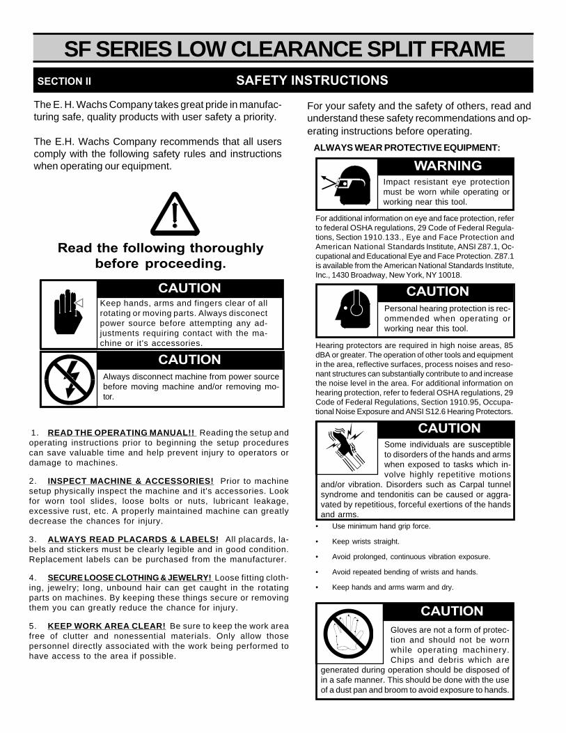
For your safety and the safety of others, read andunderstand these safety recommendations and op-erating instructions before operating.
SECTION II SAFETY INSTRUCTIONS
The E. H. Wachs Company takes great pride in manufac-turing safe, quality products with user safety a priority.
The E.H. Wachs Company recommends that all userscomply with the following safety rules and instructionswhen operating our equipment.
Read the following thoroughlybefore proceeding.
WARNINGImpact resistant eye protectionmust be worn while operating orworking near this tool.
For additional information on eye and face protection, referto federal OSHA regulations, 29 Code of Federal Regula-tions, Section 1910.133., Eye and Face Protection andAmerican National Standards Institute, ANSI Z87.1, Oc-cupational and Educational Eye and Face Protection. Z87.1is available from the American National Standards Institute,Inc., 1430 Broadway, New York, NY 10018.
Hearing protectors are required in high noise areas, 85dBA or greater. The operation of other tools and equipmentin the area, reflective surfaces, process noises and reso-nant structures can substantially contribute to and increasethe noise level in the area. For additional information onhearing protection, refer to federal OSHA regulations, 29Code of Federal Regulations, Section 1910.95, Occupa-tional Noise Exposure and ANSI S12.6 Hearing Protectors.
CAUTIONPersonal hearing protection is rec-ommended when operating orworking near this tool.
Some individuals are susceptibleto disorders of the hands and armswhen exposed to tasks which in-volve highly repetitive motions
and/or vibration. Disorders such as Carpal tunnelsyndrome and tendonitis can be caused or aggra-vated by repetitious, forceful exertions of the handsand arms.
CAUTION
Gloves are not a form of protec-tion and should not be wornwhile operating machinery.Chips and debris which are
generated during operation should be disposed ofin a safe manner. This should be done with the useof a dust pan and broom to avoid exposure to hands.
• Use minimum hand grip force.
• Keep wrists straight.
• Avoid prolonged, continuous vibration exposure.
• Avoid repeated bending of wrists and hands.
• Keep hands and arms warm and dry.
CAUTION
ALWAYS WEAR PROTECTIVE EQUIPMENT:
1. READ THE OPERATING MANUAL!! Reading the setup andoperating instructions prior to beginning the setup procedurescan save valuable time and help prevent injury to operators ordamage to machines.
2. INSPECT MACHINE & ACCESSORIES! Prior to machinesetup physically inspect the machine and it's accessories. Lookfor worn tool slides, loose bolts or nuts, lubricant leakage,excessive rust, etc. A properly maintained machine can greatlydecrease the chances for injury.
3. ALWAYS READ PLACARDS & LABELS! All placards, la-bels and stickers must be clearly legible and in good condition.Replacement labels can be purchased from the manufacturer.
4. SECURE LOOSE CLOTHING & JEWELRY! Loose fitting cloth-ing, jewelry; long, unbound hair can get caught in the rotatingparts on machines. By keeping these things secure or removingthem you can greatly reduce the chance for injury.
5. KEEP WORK AREA CLEAR! Be sure to keep the work areafree of clutter and nonessential materials. Only allow thosepersonnel directly associated with the work being performed tohave access to the area if possible.
Keep hands, arms and fingers clear of allrotating or moving parts. Always disconectpower source before attempting any ad-justments requiring contact with the ma-chine or it's accessories.
CAUTION
Always disconnect machine from power sourcebefore moving machine and/or removing mo-tor.
CAUTION
SF SERIES LOW CLEARANCE SPLIT FRAME
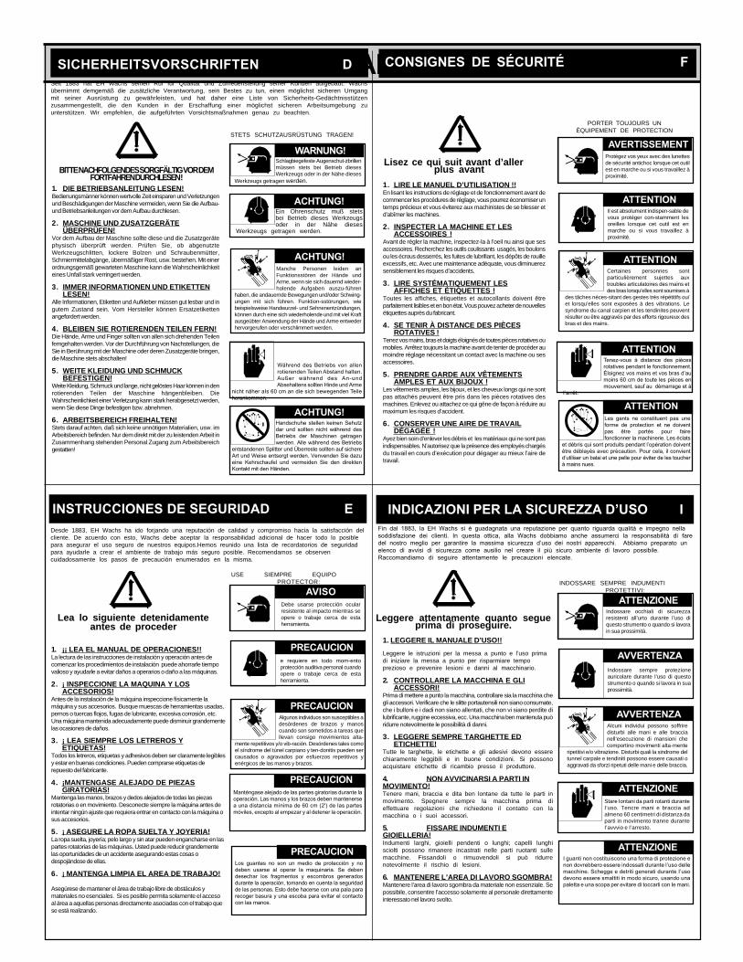
1. DIE BETRIEBSANLEITUNG LESEN!Bedienungsmänner können wertvolle Zeit einsparen und Verletzungenund Beschädigungen der Maschine vermeiden, wenn Sie die Aufbau-und Betriebsanleitungen vor dem Aufbau durchlesen.
2. MASCHINE UND ZUSATZGERÄTEÜBERPRÜFEN!
Vor dem Aufbau der Maschine sollte diese und die Zusatzgerätephysisch überprüft werden. Prüfen Sie, ob abgenutzteWerkzeugschlitten, lockere Bolzen und Schraubenmütter,Schmiermittelabgänge, übermäßiger Rost, usw. bestehen. Mit einerordnungsgemäß gewarteten Maschine kann die Wahrscheinlichkeiteines Unfall stark verringert werden.
3. IMMER INFORMATIONEN UND ETIKETTENLESEN!
Alle Informationen, Etiketten und Aufkleber müssen gut lesbar und ingutem Zustand sein. Vom Hersteller können Ersatzetikettenangefordert werden.
4. BLEIBEN SIE ROTIERENDEN TEILEN FERN!Die Hände, Arme und Finger sollten von allen sich drehenden Teilenferngehalten werden. Vor der Durchführung von Nachstellungen, dieSie in Berührung mit der Maschine oder deren Zusatzgeräte bringen,die Maschine stets abschalten!
5. WEITE KLEIDUNG UND SCHMUCKBEFESTIGEN!
Weite Kleidung, Schmuck und lange, nicht gelöstes Haar können in denrotierenden Teilen der Maschine hängenbleiben. DieWahrscheinlichkeit einer Verletzung kann stark herabgesetzt werden,wenn Sie diese Dinge befestigen bzw. abnehmen.
6. ARBEITSBEREICH FREIHALTEN!Stets darauf achten, daß sich keine unnötigen Materialien, usw. imArbeitsbereich befinden. Nur dem direkt mit der zu leistenden Arbeit inZusammenhang stehenden Personal Zugang zum Arbeitsbereichgestatten!
BITTE NACHFOLGENDES SORGFÄLTIG VOR DEMFORTFAHREN DURCHLESEN !
SICHERHEITSVORSCHRIFTEN D CONSIGNES DE SÉCURITÉ F
Lisez ce qui suit avant d’allerplus avant
1. ¡¡ LEA EL MANUAL DE OPERACIONES!!La lectura de las instrucciones de instalación y operación antes decomenzar los procedimientos de instalación puede ahorrarle tiempovalioso y ayudarle a evitar daños a operarios o daño a las máquinas.
2. ¡ INSPECCIONE LA MAQUINA Y LOSACCESORIOS!
Antes de la instalación de la máquina inspeccione físicamente lamáquina y sus accesorios. Busque muescas de herramientas usadas,pernos o tuercas flojos, fugas de lubricante, excesiva corrosión, etc.Una máquina mantenida adecuadamente puede disminuir grandementelas ocasiones de daños.
3. ¡ LEA SIEMPRE LOS LETREROS YETIQUETAS!
Todos los letreros, etiquetas y adhesivos deben ser claramente legiblesy estar en buenas condiciones. Pueden comprarse etiquetas derepuesto del fabricante.
4. ¡MANTENGASE ALEJADO DE PIEZASGIRATORIAS!
Mantenga las manos, brazos y dedos alejados de todas las piezasrotatorias o en movimiento. Desconecte siempre la máquina antes deintentar ningún ajuste que requiera entrar en contacto con la máquina osus accesorios.
5. ¡ ASEGURE LA ROPA SUELTA Y JOYERIA!La ropa suelta, joyería; pelo largo y sin atar pueden engancharse en laspartes rotatorias de las máquinas. Usted puede reducir grandementelas oportunidades de un accidente asegurando estas cosas odespojándose de ellas.
6. ¡ MANTENGA LIMPIA EL AREA DE TRABAJO!
Asegúrese de mantener el área de trabajo libre de obstáculos ymateriales no esenciales. Si es posible permita solamente el accesoal área a aquellas personas directamente asociadas con el trabajo quese está realizando.
USE SIEMPRE EQUIPOPROTECTOR:
1. LEGGERE IL MANUALE D’USO!!
Leggere le istruzioni per la messa a punto e l’uso primadi iniziare la messa a punto per risparmiare tempoprezioso e prevenire lesioni e danni al macchinario.
2. CONTROLLARE LA MACCHINA E GLIACCESSORI!
Prima di mettere a punto la macchina, controllare sia la macchina chegli accessori. Verificare che le slitte portautensili non siano consumate,che i bulloni e i dadi non siano allentati, che non vi siano perdite dilubrificante, ruggine eccessiva, ecc. Una macchina ben mantenuta puòridurre notevolmente le possibilità di danni.
3. LEGGERE SEMPRE TARGHETTE EDETICHETTE!
Tutte le targhette, le etichette e gli adesivi devono esserechiaramente leggibili e in buone condizioni. Si possonoacquistare etichette di ricambio presso il produttore.
4. NON AVVICINARSI A PARTI INMOVIMENTO!Tenere mani, braccia e dita ben lontane da tutte le parti inmovimento. Spegnere sempre la macchina prima dieffettuare regolazioni che richiedono il contatto con lamacchina o i suoi accessori.
5. FISSARE INDUMENTI EGIOIELLERIA!Indumenti larghi, gioielli pendenti o lunghi; capelli lunghisciolti possono rimanere incastrati nelle parti ruotanti sullemacchine. Fissandoli o rimuovendoli si può ridurrenotevolmente il rischio di lesioni.
6. MANTENERE L’AREA DI LAVORO SGOMBRA!Mantenere l’area di lavoro sgombra da materiale non essenziale. Sepossibile, consentire l’accesso solamente al personale direttamenteinteressato nel lavoro svolto.
Fin dal 1883, la EH Wachs si è guadagnata una reputazione per quanto riguarda qualità e impegno nellasoddisfazione dei clienti. In questa ottica, alla Wachs dobbiamo anche assumerci la responsabilità di faredel nostro meglio per garantire la massima sicurezza d’uso dei nostri apparecchi. Abbiamo preparato unelenco di avvisi di sicurezza come ausilio nel creare il più sicuro ambiente di lavoro possibile.Raccomandiamo di seguire attentamente le precauzioni elencate.
INDICAZIONI PER LA SICUREZZA D’USO I
Leggere attentamente quanto segueprima di proseguire.
1. LIRE LE MANUEL D’UTILISATION !!En lisant les instructions de réglage et de fonctionnement avant decommencer les procédures de réglage, vous pourrez économiser untemps précieux et vous éviterez aux machinistes de se blesser etd’abîmer les machines.
2. INSPECTER LA MACHINE ET LESACCESSOIRES !
Avant de régler la machine, inspectez-la à l’oeil nu ainsi que sesaccessoires. Recherchez les outils coulissants usagés, les boulonsou les écrous desserrés, les fuites de lubrifiant, les dépôts de rouilleexcessifs, etc. Avec une maintenance adéquate, vous diminuerezsensiblement les risques d’accidents.
3. LIRE SYSTÉMATIQUEMENT LESAFFICHES ET ÉTIQUETTES !
Toutes les affiches, étiquettes et autocollants doivent êtreparfaitement lisibles et en bon état. Vous pouvez acheter de nouvellesétiquettes auprès du fabricant.
4. SE TENIR À DISTANCE DES PIÈCESROTATIVES !
Tenez vos mains, bras et doigts éloignés de toutes pièces rotatives oumobiles. Arrêtez toujours la machine avant de tenter de procéder aumoindre réglage nécessitant un contact avec la machine ou sesaccessoires.
5. PRENDRE GARDE AUX VÊTEMENTSAMPLES ET AUX BIJOUX !
Les vêtements amples, les bijoux, et les cheveux longs qui ne sontpas attachés peuvent être pris dans les pièces rotatives desmachines. Enlevez ou attachez ce qui gêne de façon à réduire aumaximum les risques d’accident.
6. CONSERVER UNE AIRE DE TRAVAILDÉGAGÉE !
Ayez bien soin d’enlever les débris et les matériaux qui ne sont pasindispensables. N’autorisez que la présence des employés chargésdu travail en cours d’exécution pour dégager au mieux l’aire detravail.
STETS SCHUTZAUSRÜSTUNG TRAGEN!
PORTER TOUJOURS UNÉQUIPEMENT DE PROTECTION
INDOSSARE SEMPRE INDUMENTIPROTETTIVI:
Seit 1883 hat EH Wachs seinen Ruf für Qualität und Zufriedenstellung seiner Kunden aufgebaut. Wachsübernimmt demgemäß die zusätzliche Verantwortung, sein Bestes zu tun, einen möglichst sicheren Umgangmit seiner Ausrüstung zu gewährleisten, und hat daher eine Liste von Sicherheits-Gedächtnisstützenzusammengestellt, die den Kunden in der Erschaffung einer möglichst sicheren Arbeitsumgebung zuunterstützen. Wir empfehlen, die aufgeführten Vorsichtsmaßnahmen genau zu beachten.
Ein Ohrenschutz muß stetsbei Betrieb dieses Werkzeugsoder in der Nähe dieses
Werkzeugs getragen werden.
ACHTUNG!
INSTRUCCIONES DE SEGURIDAD EDesde 1883, EH Wachs ha ido forjando una reputación de calidad y compromiso hacia la satisfacción delcliente. De acuerdo con esto, Wachs debe aceptar la responsabilidad adicional de hacer todo lo posiblepara asegurar el uso seguro de nuestros equipos.Hemos reunido una lista de recordatorios de seguridadpara ayudarle a crear el ambiente de trabajo más seguro posible. Recomendamos se observencuidadosamente los pasos de precaución enumerados en la misma.
Lea lo siguiente detenidamenteantes de proceder
Manche Personen leiden anFunktionsstören der Hände undArme, wenn sie sich dauernd wieder-holende Aufgaben auszu-führen
haben, die andauernde Bewegungen und/oder Schwing-ungen mit sich führen. Funktion-sstörungen, wiebeispielsweise Handwurzel- und Sehnenentzündungen,können durch eine sich wiederholende und mit viel Kraftausgeübter Anwendung der Hände und Arme entwederhervorgerufen oder verschlimmert werden.
ACHTUNG!
ACHTUNG!
ACHTUNG!
Während des Betriebs von alIenrotierenden Teilen Abstand halten.Außer während des An-undAbsehaltens sollten Hinde und Arme
nicht näher aIs 60 cm an die sich bewegenden Teileherankommen.
Handschuhe stellen keinen Sehutzdar und sollten nicht während desBetriebs der Maschinen getragenwerden. Alle während des Betriebs
entstandenen Splitter und Überreste sollten auf sichereArt und Weise entsorgt werden. Venvenden Sie dazueine Kehrschaufel und vermeiden Sie den direktenKontakt mit den Händen.
Schlagbiegefeste Augenschut-zbrillenmüssen stets bei Betrieb diesesWerkzeugs oder in der Nähe dieses
Werkzeugs getragen werden.
WARNUNG!Protégez vos yeux avec des lunettesde sécurité antichoc lorsque cet outilest en marche ou si vous travaillez àproximité.
Il est absolument indispen-sable devous protéger con-stamment lesoreilles lorsque cet outil est enmarche ou si vous travaillez àproximité.
Certaines personnes sontparticulièrement sujettes auxtroubles articulatoires des mains etdes bras lorsqu’elles sont soumises à
des tâches néces-sitant des gestes très répétitifs ou/et lorsqu’elles sont exposées à des vibrations. Lesyndrome du canal carpien et les tendinites peuventrésulter ou être aggravés par des efforts rigoureux desbras et des mains.
Tenez-vous à distance des piècesrotatives pendant le fonctionnement.Èloignez vos mains et vos bras d’aumoins 60 cm de toute les pièces enmouvement, sauf au dèmarrage et à
I’arrêt.
Les gants ne constituent pas uneforme de protection et ne doiventpas être portés pour fairefonctionner la machinerie. Les éclats
et débris qui sont produits pendant l’opération doiventêtre déblayés avec précaution. Pour cela, il convientd’utiliser un balai et une pelle pour éviter de les toucherà mains nues.
AVERTISSEMENT
ATTENTION
ATTENTION
ATTENTION
ATTENTION
Indossare sempre protezioneauricolare durante l’uso di questostrumento o quando si lavora in suaprossimità.
Indossare occhiali di sicurezzaresistenti all’urto durante l’uso diquesto strumento o quando si lavorain sua prossimità.
Alcuni individui possono soffriredisturbi alle mani e alle braccianell’esecuzione di mansioni checomportino movimenti alta-mente
ripetitivi e/o vibrazione. Disturbi quali la sindrome deltunnel carpale e tendiniti possono essere causati oaggravati da sforzi ripetuti delle mani e delle braccia.
ATTENTION
ATTENZIONE
AVVERTENZA
AVVERTENZA
Stare Iontani da parti rotanti duranteI’uso. Tencre mani e braccia adalmeno 60 centimetri di distanza daparti in movimento tranne duranteI’avvvio e I’arresto.
ATTENZIONE
I guanti non costituiscono una forma di protezione enon dovrebbero essere indossati durante l’uso dellemacchine. Schegge e detriti generati durante I’usodevono essere smaltiti in modo sicuro, usando unapaletta e una scopa per evitare di toccarli con Ie mani.
ATTENZIONE
Debe usarse protección ocularresistente al impacto mientras seopere o trabaje cerca de estaherramienta.
e requiere en todo mom-entoprotección auditiva personal cuandoopere o trabaje cerca de estaherramienta.
Algunos individuos son susceptibles adesórdenes de brazos y manoscuando son sometidos a tareas quellevan consigo movimientos alta-
mente repetitivos y/o vib-ración. Desórdenes tales comoel síndrome del túnel carpiano y ten-donitis pueden sercausados o agravados por esfuerzos repetitivos yenérgicos de las manos y brazos.
ATTENTION
AVISO
PRECAUCION
PRECAUCION
PRECAUCION
PRECAUCION
Manténgase alejado de las partes giratorias durante laoperación. Las manos y los brazos deben mantenersea una distancia mínima de 60 cm (2') de las partesmóviles, excepto al empezar y al detener la operación.
Los guantes no son un medio de protección y nodeben usarse al operar la maquinaria. Se debendesechar los fragmentos y escombros generadosdurante la operación, tomando en cuenta la seguridadde las personas. Esto debe hacerse con una pala pararecoger basura y una escoba para evitar el contactocon las manos.
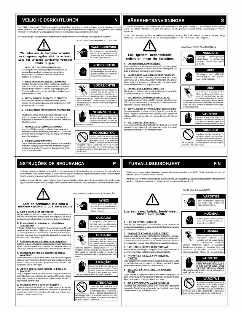
EH Wachs har sedan 1883 etablerat ett gott anseende när det gäller kvalitet och kundtillfredsställelse. Wachskänner sig därför förpliktigat att göra sitt yttersta för att garantera säkrast möjliga användning av Wachs-utrustning.
Vi har ställt samman en lista av säkerhetsanvisningar som ett led i vår strävan att skapa säkrast möjligaarbetsmiljö. Vi rekommenderar att de försiktighetsåtgärder som förtecknats följs noggrant.
VEILIGHEIDSRICHTLIJNEN N SÄKERHETSANVISNINGAR SSinds 1883 heeft de firma E.H.Wachs een reputatie opgebouwd voor kwaliteit en heeft zich geëngageerd om voldoening te schenkenaan de verbruiker. Dienovereenkomstig heeft E.H.Wachs de bijkomende verantwoordelijkheid op zich genomen het uiterste tebetrachten om het gebruik van onze apparatuur onder de meest veilige omstandigheden te verzekeren.
We hebben een lijst samengesteld van veiligheidsaanmaningen teneinde de meest veilige werkomgeving te scheppen.
DRAAG ALTIJD BESCHERMENDE UITRUSTING
1. LÄS IGENOM BRUKSANVISNINGEN!Genomläsning av anvisningarna för klargöring och drift innanklargöringen påbörjas kan medföra en värdefull tidsbesparing ochbidra till att person- och maskinskador undviks.
2. KONTROLLERA MASKINEN OCH DESS TILLBEHÖR!Kontrollera maskinen och besiktiga dess tillbehör. Se efter omverktygshållare är slitna, skruvar och muttrar lösa, smörjmedelläcker, kraftig rost förekommer o d. En korrekt underhållen maskinmedför kraftigt minskad risk för personskador.
3. LÄS ALLTID SKYLTAR OCH ETIKETTER!Alla skyltar och etiketter måste vara helt läsliga och i gott skick.Utbytesetiketter kan inköpas från tillverkaren.
4. HÅLL DIG BORTA FRÅN ROTERANDE DELAR!Håll händer, armar och fingrar borta från roterande eller rörliga delar.Slå alltid av maskinen innan justering som kräver kontakt medmaskinen eller dess tillbehör utförs.
5. STOPPA IN LÖST SITTANDE KLÄDER OCH SMYCKEN!Löst sittande kläder och smycken samt långt, hängande hår kanfastna i maskinens roterande delar. Genom att säkra dessa elleravlägsna kläder och smycken kan du minska risken för skadoravsevärt.
6. HÅLL ARBETSSTÄLLET RENT!Var noga med att hålla arbetsstället fritt från skräp och ej behövligtmaterial. Ge om möjligt tillgång till arbetsstället endast till personalsom är direkt inbegripen i det arbete som utförs.
ANVÄND ALLTID SKYDDSUTRUSTNING:
Läs igenom nedanståendeordentligt innan du fortsätter.
Stötsäkra skyddsglasögonmåste bäras vid användningav eller arbete nära dettaredskap.
Hörselskydd krävs alltid vidanvändning av eller arbetenära detta redskap.
INSTRUÇÕES DE SEGURANÇA P
1. Leia o Manual de Operações!A leitura das instruções de montagem e de funcionamento antes deiniciar os procedimentos de montagem poderá poupar um tempoprecioso e prevenir ferimentos no operador ou danos nas máquinas.
2. Inspeccione a máquina e respectivosacessórios!
Antes de efectuar a sua montagem, faça uma inspecção física damáquina e seus acessórios. Dirija a sua busca para peças deslizantesjá usadas, parafusos e porcas soltos, derrame de lubrificantes,ferrugem excessiva, etc. A manutenção adequada do maquinismodiminuirá os riscos de ferimentos.
3. Leia sempre os cartazes e as etiquetas!Todos os cartazes, etiquetas e autocolantes deverão ser claramentelegíveis e estar em perfeitas condições. Etiquetas acessórias desubstituição poderão ser encomendadas directamente do fabricante.
4. Mantenha-se fora do alcance de peçasrotatórias!
Mantenha as mãos, braços e dedos fora do alcance de todas as peçasrotatórias ou em movimento. Desligue, primeiro, a máquina sempreque tiver de proceder a ajustamentos que requeiram contacto com amáquina ou com as suas peças.
5. Aperte bem a roupa folgada e peças dejoalharia!
Roupas folgadas, joalharia e cabelo solto e comprido poderão serapanhados pelas peças rotatórias das máquinas. Manter estes artigosamarrados ou desfazer-se deles será a melhor maneira de reduzir apossibilidade de ferimentos.
6. Mantenha livre a área de trabalho !Procure manter a área de trabalho livre de ajuntamentos e de materiaisnão essenciais. O acesso a essa área só deverá ser permitido aopessoal directamente envolvido no trabalho que estiver a serexecutado, tanto quanto possível.
Já desde 1883 que a EH Wachs tem vindo a criar uma reputação de qualidade e um compromisso de satisfação dosconsumidores. Nesta linha de conduta, a Wachs tem que assumir a acrescida responsabilidade de fazer o seu melhor paragarantir a máxima segurança na utilização dos nossos equipamentos.
Acabámos de compilar uma lista de lembretes de segurança destinados a ajudar na criação de um ambiente de trabalho o maisseguro possível. Aconselhamos que sejam observadas com todo o cuidado as várias fases precaucionárias descritas a seguir.
Ante de continuar, leia com omáximo cuidado o que vai a seguir
USE SEMPRE EQUIPAMENTO DE PROTECÇÃO:
TURVALLISUUSOHJEET FIN
KÄYTÄ AINA SUOJAVÄLINEITÄ:
Käytä iskunkestäviä suojalaseja,kun käytät tätä työkalua taityöskentelet sen lähellä.
Kuulosuojainten käyttöä vaaditaanaina, kun käytät tätä työkalua taityöskentelet sen lähellä.
EH Wachs on tunnettu korkeasta laadusta ja tyytyväisistä asiakkaistaan jo vuodesta 1883. Wachs huolehtii myös siitä, ettälaitteiden käyttö on mahdollisimman turvallista.
Olemme koonneet tähän turvallisuutta koskevan muistilistan, jota noudattamalla työympäristöstä saadaan mahdollisimmanturvallinen. Kehotamme noudattamaan tässä esitettyjä varotoimenpiteitä huolellisesti.
Lue seuraavat kohdat huolellisesti,ennen kuin jatkat.
1. LUE KÄYTTÖOHJEKIRJA!Asennus- ja käyttöohjeisiin perehtyminen ennen asennuksenaloittamista säästää aikaa ja auttaa vähentämään tapaturmavaaraa jakoneiden vaurioitumisriskiä.
2. TARKASTA KONE JA LISÄLAITTEET!Ennen kuin aloitat asennuksen, tarkasta kone ja lisälaitteet. Varmista,että teräkelkat eivät ole kuluneet, pultteja ja muttereita ei ole löysällä,voiteluainetta ei vuoda, konessa ei ole liikaa ruostetta jne. Hyvässäkunnossa pidetty kone voi vähentää tapaturmavaaraa huomattavasti.
3. LUE KAIKKI KILVET JA MERKINNÄT!Kaikkien kilpien, merkintöjen ja tarrojen on oltava selkeästi luettavissaja hyvässä kunnossa. Vaihtotarroja voit ostaa valmistajalta.
4. PYSYTTELE ETÄÄLLÄ PYÖRIVISTÄOSISTA!
Pidä kädet, käsivarret ja sormet loitolla kaikista pyörivistä tai liikkuvistaosista. Kytke kone aina pois päältä ennen kuin suoritat säätöjä, joissajoudut koskemaan koneeseen tai sen lisälaitteisiin.
5. SIDO LÖYSÄT VAATTEET JA HIUKSETKIINNI!
Löysät vaatteet, korut ja pitkät hiukset voivat takertua koneen pyöriviinosiin. Vähennät tapaturmavaaraa huomattavasti, kun poistat tai sidotkiinni löysät vaatteet ja korut ja sidot hiukset kiinni.
6. PIDÄ TYÖSKENTELYALUE SIISTINÄ!Varmista, että työskentelyalueella ei ole roskia eikä tarpeetontamateriaalia. Päästä työskentelyalueelle vain käsillä olevaan työhönosallistuvia henkilöitä, mikäli mahdollista.
1. LEES HET BEDIENINGSHANDBOEK!Lees de opstel- en bedieningsrichtlijnen vooraleer met deopstelwerkzaamheden te beginnen om kostbare tijd tebesparen en om persoonlijke letsels en schade aan demachines te voorkomen.
2. INSPECTEER DE MACHINE EN TOEBEHORENVooraleer de machine op te stellen, inspecteer de machine enhaar toebehoren. Kijk uit voor versleten gereedschapssleden,losse bouten en moeren, olie lekken, overmatige roest, enz..Een goed onderhouden machine kan de kans voor kwetsurenaanzienlijk verminderen.
3. LEES ALTIJD DE PLAKKAATEN EN ETIKETTENAlle plakkaaten, etiketten en zelfklevers moeten duidelijkleesbaar zijn en in goede staat. Vervangingsetiketten kunnen bijde fabrikant gekocht worden.
4. HOUD AFSTAND VAN DRAAIENDE ONDERDELEN
Houd handen, armen en vingers weg van alle draaiende ofbewegende onderdelen. Schakel de machine uit vooraleerafregelingen te verrichten die contact vereisen met de machineof haar toebehoren.
5. VERMIJD LOSSE KLEDING EN SIERADENLos zittende kleding, sieraden, en lang los haar kunnen doordraaiende machineonderdelen gegrepen worden. Door ze vastte maken of ze te verwijderen kunt U de kans op verwondingenaanzienlijk verkleinen.
6. HOUD DE WERKRUIMTE VRIJZorg ervoor dat de werkruimte vrij is van rommel en onnodigematerialen. Toegang tot de werkruimte moet indien mogelijkenkel verleend worden aan personen die direkt betrokken zijnbij het uit te voeren werk.
We raden aan de hieronder vermeldevoorzorgsmaatregelen stipt na te leven.Lees het volgende aandachtig vooraleer
verder te gaan.
Vissa personer är känsliga för deeffekter som kan uppstå i händer ocharmar när de utför rörelser som är ihög grad repetitiva och/eller utsätts
för vibrationer. Tillstånd såsom karpal tunnel syndromoch seninflammation kan orsakas eller förvärras omhänder och armar används för att utföra repetitivt ochansträngande arbete
Pitkään jatkuva altistuminentoistuvalle liikkeelle ja/taitärinälle voi aiheuttaa käsienja käsivarsien sairauksia
joillekin henkilöille. Käsiin ja käsivarsiinkohdistuva toi-stuva ja voimakas liike voiaiheuttaa tai pahentaa sairauksia kutenrannekanavaoirey-htymä ja jännetulehdus.
Persoonlijke gehoorbescher-ming isaangeraden bij het bedienen van ditgereed-schap of bij het werken in debuurt van dit gereedschap.
Sommige personen zijn vatbaar voorhand-en arm-letsels wanneer zijbloot-gesteld zijn aan trillingen ofhandelingen die hoogst rep-etitieve
bewe-gingen ver-gen. Letsels zoals Carpal tunnel syn-droom en tendinitis kunnen veroor-zaakt worden ofverergeren door rep-etitieve krachtinspanningen vanhanden en armen.
Een veiligheidsbril moet gedra-genworden bij het bedienen van ditgereedschap of bij het werken in debuurt van dit gereedschap.
WAARSCHUWING
VOORZICHTIG
VOORZICHTIG
Blijf tijdens het bedrijf op veilige afstandvan draaiende onderdelen. Houd handenen armen minstens 5 cm weg vanbewegende onderdelen, behalve tijdens
het starten en stoppen.
VOORZICHTIG
VOORZICHTIGHandschoenen zijn geen vorm vanbescherming en mogen niet wordengedragen terwiji u de machinesbedient. Deeltjes en rommel die tijdens
het bedrijf ontstaan, moeten op een veilige manierworden opgeruimd. Dit dient te worden gedaan meteen bezem en blik om blootstelling van de handen tevoorkomen.
Sempre que trabalhar com estaferramenta ou perto dela deveráusar uma protecção para a vista, àprova de choque.
É obrigatório usar protecçãoindividual para os ouvidos durantetodo o tempo que trabalhar com estaferramenta ou perto dela.
Há pessoas que são propensas asofrer certos sintomas nas mãos ounos braços quando expostos atarefas que envol-vam movimentos
altamente repetitivos, acompanhados ou não devibrações. Sintomas como, por exemplo, o síndrome dotúnel cárpeo e a tendonite poderão ser causados ouagravados elo uso esforçado e repetitivo das mãos e dosbraços.
CUIDADO!
CUIDADO!
ATENÇÃO!
ATENÇÃO!
AVISO!
Mantenha distância das partesgiratórias durante a operação. Braçose mãos devem ser mantidos a nomínimo 2 pés (60cm) das partes
móveis, exceto durante a partida e parada.
Luvas não são uma forma deprotecção e não devem ser utilizadasdurante a operação do equipamento.Deve-se desfazer adequadamente
das lascas e aparas praduzidas durante a uso. Istodeve ser feito corn a usa de pá de lixo e vassoura paraevitar a cantata com as mãos.
Pysyttele loitolla pyörivistäosista käytön aikana. Kädetja käsivarret tulee pitäävähinään 60 cm:n päässä
liikkuvista osista paitsi käynnistyksen japysäytyksen aikana.
Käsineet eivät toimi suojavarusteina,eikä niita tule käyttää konettakäytettäessä. Käytön Aikanasyntyvät lastut ja jäte tulee hävittää
turvallisella tavalIa. Tämä tulee tehdä. Rikkalapiota jaharjaa käyttäen käsien altistumisen välttämiseksi.
HUOMAA
VAROITUS
HUOMAA
VAROITUS
VAROITUS
VARNING!
VARNING!Undvik roterande delar under drift.Händer och armar bör håIlas på minst0,6 m avstånd från rörliga delar utomnär maskinen startas eller slås från
Handskar skyddar inte och bör ejanvändas medan maskinen körs.Fusor och andra restprodukter somskapas under drift bör kasseras på
ett säkert satt. Använd kvast och sopskyffel för attundvika kontakt med händer.
VARNING!
OBS!
OBS!
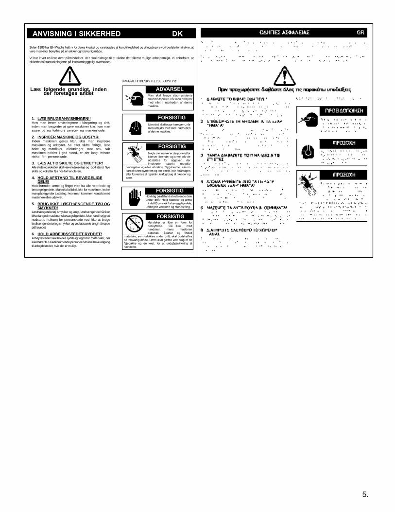
1. LÆS BRUGSANVISNINGEN!!Hvis man læser anvisningerne i klargøring og drift,inden man begynder at gøre maskinen klar, kan manspare tid og forhindre person- og maskinskade.
2. INSPICÉR MASKINE OG UDSTYR!Inden maskinen gøres klar, skal man inspiceremaskinen og udstyret. Se efter slidte fittings, løsebolte og møtrikker, olielækager, rust osv. Nårmaskinen holdes i god stand, er der langt mindrerisiko for personskade.
3. LÆS ALTID SKILTE OG ETIKETTER!Alle skilte og etiketter skal være letlæselige og i god stand. Nyeskilte og etiketter fås hos forhandleren.
4. HOLD AFSTAND TIL BEVÆGELIGEDELE!
Hold hænder, arme og fingre væk fra alle roterende ogbevægelige dele. Man skal altid slukke for maskinen, indenman påbegynder justering, hvor man kommer i kontakt medmaskinen eller udstyret.
5. BRUG IKKE LØSTHÆNGENDE TØJ OGSMYKKER!
Løsthængende tøj, smykker og langt, løsthængende hår kanblive fanget i maskinens bevægelige dele. Man kan i høj gradnedsætte risikoen for personskade ved ikke at brugeløsthængende tøj og smykker og ved at samle langt hår oppepå hovedet.
6. HOLD ARBEJDSSTEDET RYDDET!Arbejdsstedet skal holdes ryddeligt og fri for materialer, derikke hører til. Uvedkommende personer bør ikke have adgangtil arbejdsstedet, hvis det er muligt.
Læs følgende grundigt, indender foretages andet
BRUG ALTID BESKYTTELSESUDSTYR:
Man skal altid bruge høreværn, nårman arbejder med eller i nærhedenaf denne maskine.
Man skal bruge slag-resistentesikkerhedsbriller, når man arbejdermed eller i nærheden af dennemaskine.
Siden 1883 har EH Wachs haft ry for deres kvalitet og varetagelse af kundtilfredshed og vil også gøre vort bedste for at sikre, atvore maskiner benyttes på en sikker og forsvarlig måde.
Vi har lavet en liste over påmindelser, der skal bidrage til at skabe det sikrest mulige arbejdsmiljø. Vi anbefaler, atsikkerhedsforanstaltningerne på listen omhyggeligt overholdes.
ANVISNING I SIKKERHED DK
Nogle mennesker er dis-poneret forlidelser i hænder og arme, når deudsættes for opgaver, derinvolverer stærkt repetitiv
bevægelse og/eller vibration. Sygdomme, såsomkarpal-tunnelsyndrom og ten-dinitis, kan forårsageseller forværres af repetitiv, kraftig brug af hænder ogarme.
5.
Hold dig på afstand at roterende deleunder drift. Hold hænder og armemindst 60 cm væk fra bevægelige dele,undtagen ved start og stands fling.
FORSIGTIG
ADVARSEL
FORSIGTIG
FORSIGTIG
FORSIGTIGHandsker er ikke en form forbeskyttelse. Gå ikke medhandsker, mens maskinenbetjenes. Spåner og findelt
materiale, som udvikies under drift, skal bortskaffespå forsvarlig måde. Dette skal gæres ved brug at enfejebakke og en kost, for at undgåpåvirkning athænderne.

SF SERIES LOW CLEARANCE SPLIT FRAME
Portable machinery to cut and prep pipe andtubing.
EC Declaration of ConformityE.H. Wachs Company100 Shepard St.Wheeling, Il. 60090 USA
Low Clearance Split Frame Machine
LCSF/3 60-000-01 thru 60-000-36
SECTION III
Name and address of manufacturer (if different)
Distributed in the EC by:Business address:
Machine Title:
Model Number:
Machine Description:
Serial Number:
Harmonized Standards Used:
Other Safety Standards Used:
Name of person authorized to sign on behalfof the E.H. Wachs Companies:
Position:
Signature:
Date:
We declare that the machine described below conforms with the EHSR of the machinery directive89/392/EEC and amendments 91/368/EEC, 93/44/EEC and 93/68/EEC
Rodger P. Soeldner
Vice President/CFO
October 20, 1997
EN 292, EN 292-2, EN 294, EN 349
PR: EN 982, PR: EN 983: 10/95 PR: EN
792-1 PR: EN 1050
6.
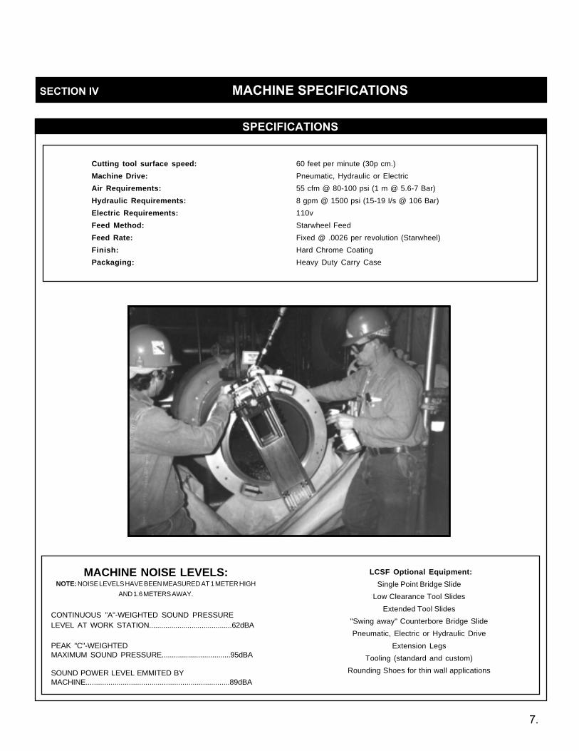
SECTION IV MACHINE SPECIFICATIONS
SPECIFICATIONS
Cutting tool surface speed: 60 feet per minute (30p cm.)
Machine Drive: Pneumatic, Hydraulic or Electric
Air Requirements: 55 cfm @ 80-100 psi (1 m @ 5.6-7 Bar)
Hydraulic Requirements: 8 gpm @ 1500 psi (15-19 I/s @ 106 Bar)
Electric Requirements: 110v
Feed Method: Starwheel Feed
Feed Rate: Fixed @ .0026 per revolution (Starwheel)
Finish: Hard Chrome Coating
Packaging: Heavy Duty Carry Case
MACHINE NOISE LEVELS:NOTE: NOISE LEVELS HAVE BEEN MEASURED AT 1 METER HIGH
AND 1.6 METERS AWAY.
CONTINUOUS "A"-WEIGHTED SOUND PRESSURELEVEL AT WORK STATION.........................................62dBA
PEAK "C"-WEIGHTEDMAXIMUM SOUND PRESSURE..................................95dBA
SOUND POWER LEVEL EMMITED BYMACHINE......................................................................89dBA
LCSF Optional Equipment:
Single Point Bridge Slide
Low Clearance Tool Slides
Extended Tool Slides
"Swing away" Counterbore Bridge Slide
Pneumatic, Electric or Hydraulic Drive
Extension Legs
Tooling (standard and custom)
Rounding Shoes for thin wall applications
7.

SF SERIES LOW CLEARANCE SPLIT FRAME
SET UP&
OPERATINGPROCEDURES
SECTION V

SF SERIES LOW CLEARANCE SPLIT FRAME
A. Pre-Setup Inspection:
Split Frame Machine:The LCSF ring consists of one rotating ring and onestationary ring. Each ring splits into two pieces. Whenassembeled the rotating ring and stationary rings areintegrated and split apart simultaneously for mounting on in-line piping applications. These rings are pre-assembled and adjusted prior to leaving the factory.
Tool Slides:Wachs manufactures three sizes of tool slides forthe LCSF; these are the Low Clearance, Extendedand Super Extended slides. The low clearanceslides are special order slides used when minimalradial clearance is required. Extended slides are commonly referred to as "standard" slides on split framesup to LCSF 1420. Super extended slides are used onLCSF a1824 through LCSF 3036. Check the packinglist to see which slides you should have recievedwith your Split Frame.
Clamp Pad Extensions:These are necessary for the LCSF to cover its entirerange of pipe diameters. Check Clamp Pad Chart onpage 22 and 23 for size required for pipe diameterbeing cut.
Trip Assembly:The trip assembly is comprised of a trip housing, atrip pin and two extension blocks. The trip can beengaged or disengaged depending upon feed require-ments, by lowering or raising the trip pin. Refer toTool Slide Mounting Location and Trip Assembly Configuration on page 15.
Air Motor:Wachs Low Clearance Split Frames have two air mo-tors available according to Split Frame size and ap-plication requirements.Generally, LCSF models 051through 1420 are equipped with a 1-1/2 hp motor whilemodels 1824 and above are equipped with a 2-1/2 hpmotor. Both motors are interchangeable by designand can be used on any size Split Frame as needed.
Tool Kit:Each LCSF is delivered from the factory with all handtools necessary for setup and operation.
Counterbore Slide (optional):This attachment is used for precision I.D. machining.Check the packing list to see if this attachment ispart of your Split Frame package.
B. Split Frame Mounting & Setup Procedures:
NOTE: Occasionally wewill reference the SplitFrame to the positions ona clock. The positins areoutlined in illustration A.
1. Remove the LCSF from the storage case. ( LCSF 051through 1420 are packaged in a plastic carrying case.1824 and above are housed in a custom wooden storagecontainer.)
2. Insert the frame locking detent pins (figure 1). Thesepins prevent the machine halves from separating whenthe machine is split for in-line pipe cutting applications.
3. Install the tool slides. For this procedure it will beassumed that the "standard" or extended slides are beingused.
NOTE: Low Clearance Tool Slides have only one mount-ing position, Super Extended have three.
4. On the back of each of the tool slides are two rows ofthree holes and two fast pins (see illustration B). The holesrepresent the three possible mounting positions; high,midand low range. Drop one mounting pin location for every2” drop in pipe size from Split Frame’s maximum size.
SECTION V SET-UP AND OPERATION
CAUTION: On LCSF machines 1824 and aboveit will be necessary to utilize additional person-nel and/or equipment such as adequate riggingmaterials to install machine and avoid injury topersonnel and damage to equipment.
ILLUSTRATION A
8.
SF SERIES LOW CLEARANCE SPLIT FRAME SECTION V SET-UP AND OPERATION (cont.)
9.
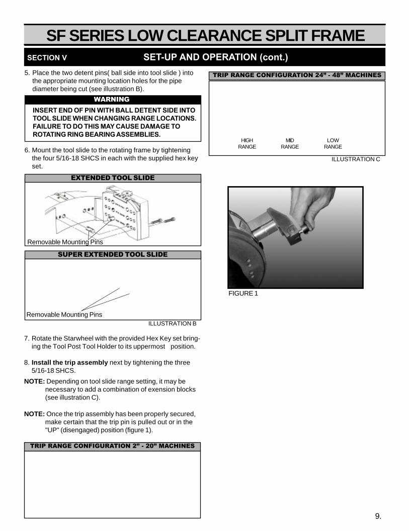
5. Place the two detent pins( ball side into tool slide ) intothe appropriate mounting location holes for the pipediameter being cut (see illustration B).
6. Mount the tool slide to the rotating frame by tighteningthe four 5/16-18 SHCS in each with the supplied hex keyset.
7. Rotate the Starwheel with the provided Hex Key set bring-ing the Tool Post Tool Holder to its uppermost position.
8. Install the trip assembly next by tightening the three5/16-18 SHCS.
NOTE: Depending on tool slide range setting, it may benecessary to add a combination of exension blocks(see illustration C).
ILLUSTRATION C
HIGHRANGE
MIDRANGE
LOWRANGE
TRIP RANGE CONFIGURATION 24” - 48” MACHINES
EXTENDED TOOL SLIDE
WARNINGINSERT END OF PIN WITH BALL DETENT SIDE INTOTOOL SLIDE WHEN CHANGING RANGE LOCATIONS.FAILURE TO DO THIS MAY CAUSE DAMAGE TOROTATING RING BEARING ASSEMBLIES.
NOTE: Once the trip assembly has been properly secured,make certain that the trip pin is pulled out or in the"UP" (disengaged) position (figure 1).
FIGURE 1
SUPER EXTENDED TOOL SLIDE
ILLUSTRATION BRemovable Mounting Pins
Removable Mounting Pins
TRIP RANGE CONFIGURATION 2” - 20” MACHINES
SF SERIES LOW CLEARANCE SPLIT FRAME
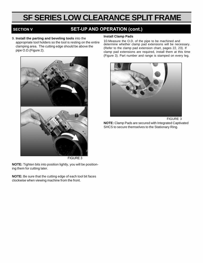
NOTE: Tighten bits into position lightly, you will be position-ing them for cutting later.
NOTE: Be sure that the cutting edge of each tool bit facesclockwise when viewing machine from the front.
9. Install the parting and beveling tools into theappropriate tool holders so the tool is resting on the entireclamping area. The cutting edge should be above thepipe O.D.(Figure 2).
FIGURE 3
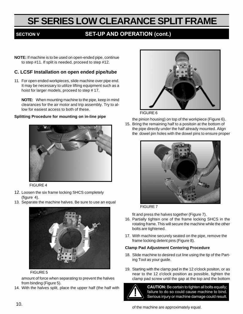
Install Clamp Pads10.Measure the O.D. of the pipe to be machined anddetermine whether clamp pad extensions will be necessary.(Refer to the clamp pad extension chart, pages 22, 23). Ifclamp pad extensions are required, install them at this time(Figure 3). Part number and range is stamped on every leg.
NOTE: Clamp Pads are secured with Integrated CaptivatedSHCS to secure themselves to the Stationary Ring.
FIGURE 3
SECTION V SET-UP AND OPERATION (cont.)
SF SERIES LOW CLEARANCE SPLIT FRAME SECTION V SET-UP AND OPERATION (cont.)
10.
NOTE: If machine is to be used on open-ended pipe, continueto step #11. If split is needed, proceed to step #12.
C. LCSF Installation on open ended pipe/tube
11. For open ended workpieces, slide machine over pipe end.It may be necessary to utilize lifting equipment such as ahoist for larger models, proceed to step # 17.
NOTE: When mounting machine to the pipe, keep in mindclearances for the air motor and trip assembly. Try to al-low for easiest access to both of these.
Splitting Procedure for mounting on in-line pipe
12. Loosen the six frame locking SHCS completely(figure 4).
13. Separate the machine halves. Be sure to use an equal
amount of force when separating to prevent the halvesfrom binding (Figure 5).
14. With the halves split, place the upper half (the half with
the pinion housing) on top of the workpiece (Figure 6).15. Bring the remaining half to a positoin at the bottom of
the pipe directly under the half already mounted. Alignthe dowel pin holes with the dowel pins to ensure proper
fit and press the halves together (Figure 7).16. Partially tighten one of the frame locking SHCS in the
rotating frame. This will secure the machine while the otherbolts are tightened.
17. With machine securely seated on the pipe, remove theframe locking detent pins (Figure 8).
Clamp Pad Adjustment Centering Procedure
18. Slide machine to desired cut line using the tip of the Part-ing Tool as your guide.
19. Starting with the clamp pad in the 12 o'clock positon, or asnear to the 12 o'clock position as possible, tighten theclamp pad screw until the gap at the top and the bottom
of the machine are approximately equal.
FIGURE 6
CAUTION: Be certain to tighten all bolts equally;failure to do so could cause machine to bind.Serious injury or machine damage could result.
FIGURE 7
FIGURE 4
FIGURE 5

SF SERIES LOW CLEARANCE SPLIT FRAME SECTION V SET-UP AND OPERATION (cont.)
11.
20. Snug the clamp pad at the 6 o’clock position.
21. Move to the 3 and 9 o'clock positions. At this point themachine should be fairly square.
22. Rough square the machine using the provided square.Check the LCSF's squareness to the pipe O.D.
NOTE: The machine should still be able to be shiftedslightly at this time. If necessary, SLIGHTLY loosen theclamp pads at the 3 and 9 o'clock positions and re adjustas needed.
23. Once the machine is square to the pipe, tighten the framelocking SHCS completely.
D. LCSF Centering
24. Manually rotate the parting tool to the 12 o'clockposition.
25. Lower the tool until it is roughly 1/8" above thepipe O.D.
26. Rotate the tool to the 6 o'clock position and addjust the clamp pad as necessary to center.
NOTE:If tool is closer to the pipe at the 6 o'clock position
than at the 12 o'clock position, loosen the clamp pad at12 o'clock SLIGHTLY and tighten the clamp pad at the 6o'clock position. This will effectively move the tool away at6 o'clock and closer at 12 o'clock further centering ma-chine.
E. Tooling Adjustment Procedure
27. At this time, adjust your tooling to ensure proper opera-tion and avoid damage to the machine.
a. the parting tool should extend beyond the bottom ofthe tool holder a distance equal to the wall thicknessof the workpiece plus 1/8".
b. The beveling tool should extend beyond the bottomof the tool holder a distance equal to the wall thick-ness of the workpiece plus 1/8".
28. Secure tools in place by installing the tool holder cover
plates. Tighten the four corner bolts on each tool holdercover (figure 9).
NOTE: In the case of the Parting Tool, be sure that thegap between the cover plate and the tool holder is equalon either side of the parting tool.
29. With the cover plates installed, snug the two remainingSHCS on each cover plate as well as the single SHCS onthe side of the beveling tool holder.
30. Time the starwheel feed system.
a. Always rotate the starwheel counter clockwise. Besure to remove all backlash from the feed screw andthe feed nut.
b. Align any point of the starwheel with the red line onthe top of the tool slide (see illustration D on followingpage).
FIGURE 8
FIGURE 9
CAUTION: Be sure that all frame locking SHCSare equally tightened before continuing withmounting procedure. Failure to do so may causedamage to drive gears.
SF SERIES LOW CLEARANCE SPLIT FRAME
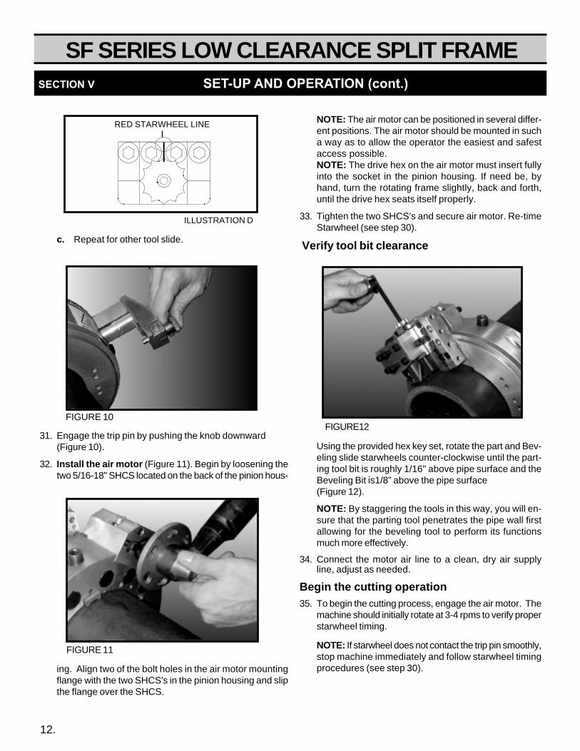
c. Repeat for other tool slide.
31. Engage the trip pin by pushing the knob downward(Figure 10).
32. Install the air motor (Figure 11). Begin by loosening thetwo 5/16-18" SHCS located on the back of the pinion hous-
ing. Align two of the bolt holes in the air motor mountingflange with the two SHCS's in the pinion housing and slipthe flange over the SHCS.
NOTE: The air motor can be positioned in several differ-ent positions. The air motor should be mounted in sucha way as to allow the operator the easiest and safestaccess possible.NOTE: The drive hex on the air motor must insert fullyinto the socket in the pinion housing. If need be, byhand, turn the rotating frame slightly, back and forth,until the drive hex seats itself properly.
33. Tighten the two SHCS's and secure air motor. Re-timeStarwheel (see step 30).
Verify tool bit clearance
Using the provided hex key set, rotate the part and Bev-eling slide starwheels counter-clockwise until the part-ing tool bit is roughly 1/16" above pipe surface and theBeveling Bit is1/8” above the pipe surface(Figure 12).
NOTE: By staggering the tools in this way, you will en-sure that the parting tool penetrates the pipe wall firstallowing for the beveling tool to perform its functionsmuch more effectively.
34. Connect the motor air line to a clean, dry air supplyline, adjust as needed.
Begin the cutting operation35. To begin the cutting process, engage the air motor. The
machine should initially rotate at 3-4 rpms to verify properstarwheel timing.
NOTE: If starwheel does not contact the trip pin smoothly,stop machine immediately and follow starwheel timingprocedures (see step 30).
SECTION V SET-UP AND OPERATION (cont.)
FIGURE 11
FIGURE12FIGURE 10
12.
RED STARWHEEL LINE
ILLUSTRATION D
SF SERIES LOW CLEARANCE SPLIT FRAME
36. Increase speed to roughly 10-12 rpm.
37. Once the tool bits begin to remove material from theworkpiece, be sure to apply liberal amounts of coolant forthe duration of the machining process.
NOTE: If counterboring will be performed, take care toleave an oversized land. This will allow for the opening ofthe pipe I.D.
38. If counterboring is to be performed, proceed to step num-ber 25. If no counterbore is to be performed, skip to “Ma-chine Disassembly and Removal” on the next page.
SECTION V SET-UP AND OPERATION (cont.)
F. Counterbore Set-up and Operation39. Return the parting and beveling tools to their uppermost
(12 and 6 o’clock) position by rotating starwheels clock-wise (Figure 13).
40. Remove the trip assembly.
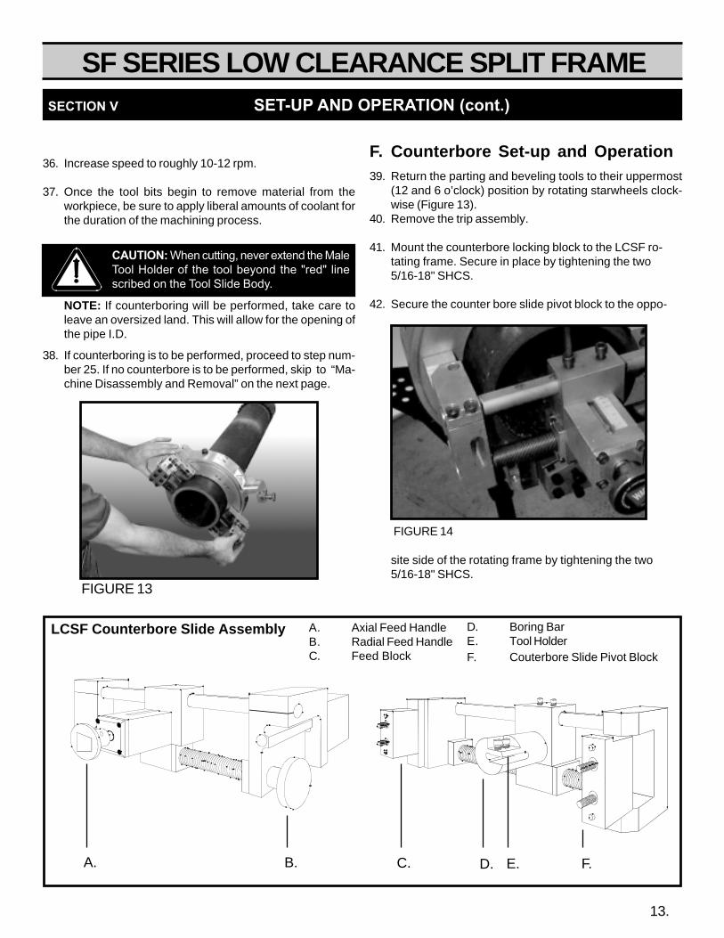
41. Mount the counterbore locking block to the LCSF ro-tating frame. Secure in place by tightening the two5/16-18" SHCS.
42. Secure the counter bore slide pivot block to the oppo-
site side of the rotating frame by tightening the two5/16-18" SHCS.
FIGURE 13
13.
CAUTION: When cutting, never extend the MaleTool Holder of the tool beyond the "red" linescribed on the Tool Slide Body.
A. Axial Feed HandleB. Radial Feed HandleC. Feed Block
LCSF Counterbore Slide Assembly D. Boring BarE. Tool HolderF. Couterbore Slide Pivot Block
C. D. E. F.A. B.
FIGURE 14
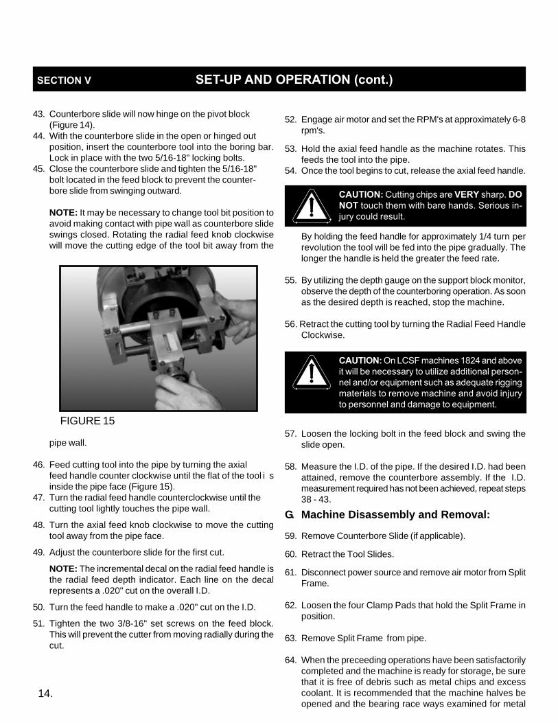
43. Counterbore slide will now hinge on the pivot block(Figure 14).
44. With the counterbore slide in the open or hinged outposition, insert the counterbore tool into the boring bar.Lock in place with the two 5/16-18" locking bolts.
45. Close the counterbore slide and tighten the 5/16-18"bolt located in the feed block to prevent the counter-bore slide from swinging outward.
NOTE: It may be necessary to change tool bit position toavoid making contact with pipe wall as counterbore slideswings closed. Rotating the radial feed knob clockwisewill move the cutting edge of the tool bit away from the
pipe wall.
46. Feed cutting tool into the pipe by turning the axialfeed handle counter clockwise until the flat of the tool i sinside the pipe face (Figure 15).
47. Turn the radial feed handle counterclockwise until thecutting tool lightly touches the pipe wall.
48. Turn the axial feed knob clockwise to move the cuttingtool away from the pipe face.
49. Adjust the counterbore slide for the first cut.
NOTE: The incremental decal on the radial feed handle isthe radial feed depth indicator. Each line on the decalrepresents a .020" cut on the overall I.D.
50. Turn the feed handle to make a .020" cut on the I.D.
51. Tighten the two 3/8-16" set screws on the feed block.This will prevent the cutter from moving radially during thecut.
SECTION V SET-UP AND OPERATION (cont.)
14.
FIGURE 15
52. Engage air motor and set the RPM's at approximately 6-8rpm's.
53. Hold the axial feed handle as the machine rotates. Thisfeeds the tool into the pipe.
54. Once the tool begins to cut, release the axial feed handle.
By holding the feed handle for approximately 1/4 turn perrevolution the tool will be fed into the pipe gradually. Thelonger the handle is held the greater the feed rate.
55. By utilizing the depth gauge on the support block monitor,observe the depth of the counterboring operation. As soonas the desired depth is reached, stop the machine.
56. Retract the cutting tool by turning the Radial Feed HandleClockwise.
57. Loosen the locking bolt in the feed block and swing theslide open.
58. Measure the I.D. of the pipe. If the desired I.D. had beenattained, remove the counterbore assembly. If the I.D.measurement required has not been achieved, repeat steps38 - 43.
G. Machine Disassembly and Removal:
59. Remove Counterbore Slide (if applicable).
60. Retract the Tool Slides.
61. Disconnect power source and remove air motor from SplitFrame.
62. Loosen the four Clamp Pads that hold the Split Frame inposition.
63. Remove Split Frame from pipe.
64. When the preceeding operations have been satisfactorilycompleted and the machine is ready for storage, be surethat it is free of debris such as metal chips and excesscoolant. It is recommended that the machine halves beopened and the bearing race ways examined for metal
CAUTION: On LCSF machines 1824 and aboveit will be necessary to utilize additional person-nel and/or equipment such as adequate riggingmaterials to remove machine and avoid injuryto personnel and damage to equipment.
CAUTION: Cutting chips are VERY sharp. DONOT touch them with bare hands. Serious in-jury could result.

SF SERIES LOW CLEARANCE SPLIT FRAME
MACHINE ADJUSMENTS&
MAINTENANCE
SECTION VI
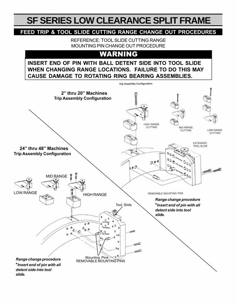
SF SERIES LOW CLEARANCE SPLIT FRAMEFEED TRIP & TOOL SLIDE CUTTING RANGE CHANGE OUT PROCEDURES
REFERENCE: TOOL SLIDE CUTTING RANGEMOUNTING PIN CHANGE OUT PROCEDURE
LOW RANGE
MID RANGE
HIGH RANGE
Tool Slide
Mounting Pins
2” thru 20” Machines
24” thru 48” Machines
WARNINGINSERT END OF PIN WITH BALL DETENT SIDE INTO TOOL SLIDEWHEN CHANGING RANGE LOCATIONS. FAILURE TO DO THIS MAYCAUSE DAMAGE TO ROTATING RING BEARING ASSEMBLIES.
Trip Assembly Configuration
Trip Assembly Configuration
Range change procedure*Insert end of pin with alldetent side into toolslide.
REMOVABLE MOUNTING PINS
Range change procedure*Insert end of pin with alldetent side into toolslide.

SF SERIES LOW CLEARANCE SPLIT FRAME
1. WITH ROTATING FRAME REMOVED, INSTALL ECCEN-TRIC SHAFT, WHEEL BEARING, AND SPACER ONTOSTATIONARY FRAME ASSEMBLY.
2. LIGHTLY FASTEN WITH 5/16 AN WASHER AND5/16-18 NYLOCK NUT.
3. TURN ALL ECCENTRIC SHAFTS TO THE “BOTTOM”POSITION (USING A 3/16" HEX KEY OR “T HANDLE),AS INDICATED BY THE LINE MACHINED INTO EACHBEARING. AT THIS POINT ALL LINES SHOULD POINTTOWARD THE MACHINE’S I.D.
4. SLIDE ROTATING FRAME INTO STATIONARY FRAME.SECURE ALL CAPTIVATED FRAME LOCKING SETSCREWS.
NOTE: PAY SPECIAL ATTENTION TO THE ROTATINGFRAME LOCKING SCREWS.
NOTE: PRIOR TO ATTEMPTING TO ADJUST “V” BEAR-INGS, BOTH TOOL SLIDES MUST BE REMOVED.
5. PLACE BEARING PRELOAD PLATES (#60-205-00) ATTHE #1 AND #2 POSITIONS (SEE CORRESPONDINGDIAGRAM)
6. PLACE 1 HEX DRIVE ADAPTER (1/4" TO 3/16") INEACH POSITION. THIS IS DONE BY INSERTING THEDRIVER INTO THE HOLE IN BEARING PRELOADPLATE.
7. ONCE DRIVE ADAPTER IS PROPERLY SEATED INTOTHE ECCENTRIC SHAFT, SECURE BEARING PRELOAD PLATE WITH TWO 5/16-18 x 5/8 SHCS.
8. STARTING AT THE #1 POSITION, TOUCH BEARINGOFF TO THE ROTATING FRAME “V’ GROOVE. SNUG5/16-18 NYLOCK NUT BUT DO NOT TIGHTEN COM-PLETELY.
9. PROCEED TO THE #2 POSITION AND REPEAT STEP#8. DO THE SAME FOR POSITIONS #3 AND #4.
10. RETURN TO POSITION #1 AND TORQUE BEARINGTO 7 INCH POUNDS MINIMUM USING APPROPRI-ATE TORQUE WRENCH.
11. MOVE TO POSITIONS 2,3, AND 4 AND REPEAT STEP#10.
12. WITH BEARINGS AT POSITIONS #1-4 SECURE, TWOCHECKS MUST BE CONDUCTED TO INSUREPROPER BEARING ALIGNMENT AND PRELOAD
1. CHECK MACHINE RINGS FOR SQUARENESSUSING PROVIDED SQUARE. I.D. OF BOTHRINGS SHOULD BE FLUSH WITH ONE ANOTHER.
2. CHECK PINION BACKLASH. TO DO THIS THEPINION HOUSING MUST BE MOUNTED TO THEMACHINE.
13. RETURN TO THE #1 POSITION. USING THE “INCHPOUND” TORQUE WRENCH THE 5/16-18 NYLOCK NUTEACH POSITION TO 150 INCH POUNDS.
14. CHECK FLUSHNESS AT EACH OF THE FOUR POSI-TIONS ADJUSTED ONCE AGAIN.
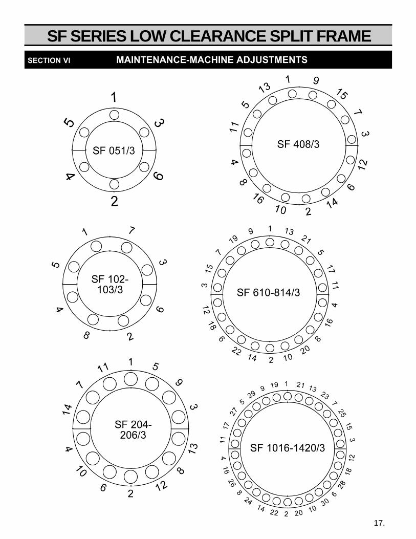
15. ONCE POSITIONS #144 HAVE BEEN PROPERLY ADJUSTED, FOLLOW THE NUMERIC SEQUENCE OF THECORRESPONDING DIAGRAM AND REPEAT THE SAMEPROCEEDURE FOR ALL REMAINING BEARINGS.
“V” BEARING ADJUSTMENT PROCEDURE
SECTION VI MAINTENANCE-MACHINE ADJUSTMENTS
16.
SF SERIES LOW CLEARANCE SPLIT FRAME SECTION VI MAINTENANCE-MACHINE ADJUSTMENTS
17.

SF SERIES LOW CLEARANCE SPLIT FRAME SECTION VI MAINTENANCE-LUBRICATION
LCSFLubrication Information:
Tool Slide # 60-416-00 / 60-415-00
Point of Application: All moving parts.Service Interval: Every 10 hrs. of operationType of Lubricant: Mobil-lith AW-2 or Equivalent
Pinion Gear Housing
Point of Application: Front needle bearing ( # 60-126-00 )Service Interval: Every 50 hrs. of operationType of Lubricant: Mobil-lith AW-2 or Equivalent
18.

SECTION VII
OPERATIONALCHARTS
&GRAPHS

SF SERIES LOW CLEARANCE SPLIT FRAME
RADIAL AND AXIAL CLEARANCEDIAGRAM AND CHART
SECTION VII MISCELLANEOUS CHARTS AND GRAPHS
60-402-01 (PARTING)60-403-01 (BEVEL)
60-402-04 (PARTING)60-403-04 (BEVEL)
STAR FEED
60-418-00 (PARTING)60-419-00 (BEVEL)
CAM FEED
60-415-00 (PARTING)60-416-00 (BEVEL)
STAR FEED
60-437-00 (PARTING)60-438-00 (BEVEL)
STAR FEED
A
B(MAX)
C
SLIDE#60-415-00 SHOWNON 4” MACHINE
21.
MODEL SF 204/3 SF 206/3 SF 408/3 SF 610/3 SF 612/3 SF 814/3 SF 1016/3 SF 1420/3 SF 1824 SF 2228 SF 2632 SF 3036 SF 3642 SF 4248
“A” Dim. (inches) 4.75 6.88 8.88 11.0 13.0 14.25 16.25 20.25 24.5 28.5 32.5 36.5 42.5” 48.5
“A’ Dim (millimeters) 121.60 176.12 227.32 279.40 330.20 361.95 412.75 514.35 622.30 723.90 825.50 927.10 1079.5 1219.2
LOW CLEARANCE TOOL SLIDE (TOOL STROKE: .50”) (12.7MM) USING SLIDE # 60-402-01/04
“B” DIM. (INCH) 4.50” 5.56” 6.56” 7.88” 8.88” 9.50” 10.75” 12.75” -- -- -- -- -- --
“B” DIM. (mm) 114.3 141.22 166.62 200.15 225.55 241.3 273.05` 323.85 -- -- -- -- -- --
“C” DIM. (INCH) 6.0” 6.0” 6.0” 6.0” 6.0” 6.0” 6.0” 6.0” -- -- -- -- -- --
“C” DIM. (mm) 152.40 152.40 152.40 152.40 152.40 152.40 152.40 152.40 -- -- -- -- -- --
EXTENDED TOOL SLIDE (TOOL STROKE: 1.50”) (50.8 mm) USING SLIDE #60-415-00
“B” DIM. (INCH) 6.45” 7.51” 8.51” 9.94” 10.94” 11.45” 12.70” 14.70” 16.63” 18.63” 20.63” 22.63” -- --
“B” DIM. (mm) 163.83 190.75 216.15 252.47 277.87 290.83 322.58 373.38 422.40 473.20 524.00 574.80 -- --
“C” DIM. (INCH) 6.0” 6.0” 6.0” 6.0” 6.0” 6.0” 6.0” 6.0” 7.0” 7.0” 7.0” 7.0” -- --
“C” DIM. (mm) 152.40 152.40 152.40 152.40 152.40 152.40 152.40 152.40 177.80 177.80 177.80 177.80 -- --
SUPER EXTENDED TOOL SLIDE (TOOL STROKE 2.00”) (50.8mm) USING SLIDE # 60-437-00
“B” DIM. (INCH) -- -- -- -- -- -- -- -- 19.0” 21.0” 23.0” 25.0” 28 31
“B” DIM. (mm) -- -- -- -- -- -- -- -- 482.60 533.40 584.20 635.00 711.2 787.4
“C” DIM. (INCH) -- -- -- -- -- -- -- -- 7.0” 7.0” 7.0” 7.0” 7” 7”
“C” DIM. (mm) -- -- -- -- -- -- -- -- 177.80 177.80 177.80 177.80 177.80 177.80
MACHINE CAPACITY:
INCHES: 1-4” 2-6” 4-8” 6-10” 6-12” 8-14” 10-16” 14-20” 18-24” 22-28” 26-32” 30-36”36-42 42-48MM: 51-152 102-204 152-254 152-254 152-305 203-356 254-406 356-508 457-610 559-711 660-812 812-914 914.4-1066.8 1066.8-1219.2
WEIGHT:
(LBS); 30 37 43 53 63 73 88 103 175 200 230 260 310 360(KGS): 13.6 16.78 19.5 24.04 28.57 33.11 39.91 46.72 79.38 90.72 104.32 117.93 140.6 163.29

SF SERIES LOW CLEARANCE SPLIT FRAME
WITH NO MAX. 8.63 219.20 10.75 273.05 12.75 323.85 14.00 355.00 16.00 406.40 EXTENSION MIN. 7.63 193.80 9.50 241.30 11.50 292.10 12.75 323.85 14.75 374.65
60-408-05 MAX 7.63 193.80 9.75 247.65 11.75 298.45 13.00 330.20 15.00 381.001/2” EXT. SET MIN. 6.63 168.40 8.50 215.90 10.50 266.70 11.75 298.45 13.75 349.25
60-408-07 MAX. 7.13 181.10 9.25 234.95 11.25 285.75 12.50 317.50 14.50 368.303/4" EXTSET MN. 6.13 155.70 8.00 203.20 10.00 254.00 11.25 285.75 13.25 336.55
60-408-10 MAX. 6.63 168.40 8.75 222.25 10.75 273.05 12.00 304.80 14.00 355.60 1” EXT SET MIN. 5.63 143.00 7.50 190.56 9.50 241.30 10.75 273.05 12.75 323.85
60-408-15 MAX. 5.63 143.00 7.75 196.85 9.75 247.65 11.00 279.40 13.00 304.801-1/2" EXT SET MIN. 4.63 117.60 6.50 165.10 8.50 215.90 9.75 247.65 11.75 298.45
60-408-20 MAX. 4.63 117.60 6.75 171.45 8.75 222.25 10.00 254.00 12.00 304.80 2" EXT SET MIN. 3.63 92.20 5.50 139.70 7.50 190.50 8.75 222.25 2.00 273.05
00-406-25 MAX. 7.75 196.85 9.00 228.60 11.00 279.402-1/2" EXTSET MN. 6.50 165.10 7.75 196.85 9.75 247.65
60-408-40 MAX. 6.75 171.45 3" EXT SET MIN. 5.50 139.70
60-408-31 MAX.3-1/8" EXT SET MIN.
WITH NO MAX. 1.32* 33.53 2.38 60.45 3.50 88.90 4.50 114.30 6.83 168.40 EXTENSION MIN. .57* 14.48* 1.63 41.40 2.75 69.85 3.50 88.90 5.63 143.00
60-408-05 MAX. 2.50 63.50 3.50 88.90 5.63 143.001/2" EXTSET MIN. 1.75 44.45 2.50 63.50 4.63 117.60
60-408-07 MAX. 2.00 50.80 3.00 76.20 5.13 130.303/4" EXTSET MN. 1.63 41.40 2.00 50.80 4.13 104.90
60-408-10 MAX. 2.50 63.50 4.63 117.60 1” EXT SET MIN. · 2.00 50.80 3.63 92.20
60-408-15 MAX. 3.63 92.201-1/2" EXT SET MIN. 2.63 66.80
60-408-20 MAX. 2.63 66.80 2" EXT SET MIN. 2.00 50.80
00-406-25 MAX.2-1/2" EXTSET MN.
60-408-40 MAX. 3" EXT SET MIN.
60-408-31 MAX.3-1/8" EXT SET MIN.
1234567890123456789012345678901212345678901234567890123456789012345678901234567890121234567890123456789012345678901234567890123456789012123456789012345678901234567890123456789012345678901212345678901234567890123456789012345678901234567890121234567890123456789012345678901234567890123456789012123456789012345678901234567890123456789012345678901212345678901234567890123456789012345678901234567890121234567890123456789012345678901234567890123456789012123456789012345678901234567890123456789012345678901212345678901234567890
12345678901234567890123456789012123456789012345678901234567890121234567890123456789012345678901212345123456789012345678901234567890121234567890123456789012345678901212345678901234567890123456789012123451234567890123456789012345678901212345678901234567890123456789012123456789012345678901234567890121234512345678901234567890123456789012123456789012345678901234567890121234567890123456789012345678901212345123456789012345678901234567890121234567890123456789012345678901212345678901234567890123456789012123451234567890123456789012345678901212345678901234567890123456789012123456789012345678901234567890121234512345678901234567890123456789012123456789012345678901234567890121234567890123456789012345678901212345123456789012345678901234567890121234567890123456789012345678901212345678901234567890123456789012123451234567890123456789012345678901212345678901234567890123456789012123456789012345678901234567890121234512345678901234567890123456789012123456789012345678901234567890121234567890123456789012345678901212345
1234567890123456789012345678901212345678901234567890123456789012123456789012123456789012345678901234567890121234567890123456789012345678901212345678901212345678901234567890123456789012123456789012345678901234567890121234567890121234567890123456789012345678901212345678901234567890123456789012123456789012123456789012345678901234567890121234567890123456789012345678901212345678901212345678901234567890123456789012123456789012345678901234567890121234567890121234567890123456789012345678901212345678901234567890123456789012123456789012123456789012345678901234567890121234567890123456789012345678901212345678901212345678901234567890123456789012123456789012345678901234567890121234567890121234567890123456789012345678901212345678901234567890123456789012123456789012
123456789012345678901234567890121234567890123456789123456789012345678901234567890121234567890123456789123456789012345678901234567890121234567890123456789123456789012345678901234567890121234567890123456789123456789012345678901234567890121234567890123456789123456789012345678901234567890121234567890123456789123456789012345678901234567890121234567890123456789123456789012345678901234567890121234567890123456789123456789012345678901234567890121234567890123456789123456789012345678901234567890121234567890123456789
123456789012345678901234567890121234567890123456789123456789012345678901234567890121234567890123456789123456789012345678901234567890121234567890123456789123456789012345678901234567890121234567890123456789123456789012345678901234567890121234567890123456789123456789012345678901234567890121234567890123456789123456789012345678901234567890121234567890123456789123456789012345678901234567890121234567890123456789123456789012345678901234567890121234567890123456789123456789012345678901234567890121234567890123456789
CLAMPING RANGE SF051 SF102 SF103 SF204 SF206
1234567890123456789012345678901212345678901234567890123456789012123456789012345678901234567890121234567890123456789012345678901123456789012345678901234567890121234567890123456789012345678901212345678901234567890123456789012123456789012345678901234567890112345678901234567890123456789012123456789012345678901234567890121234567890123456789012345678901212345678901234567890123456789011234567890123456789012345678901212345678901234567890123456789012123456789012345678901234567890121234567890123456789012345678901123456789012345678901234567890121234567890123456789012345678901212345678901234567890123456789012123456789012345678901234567890112345678901234567890123456789012123456789012345678901234567890121234567890123456789012345678901212345678901234567890123456789011234567890123456789012345678901212345678901234567890123456789012123456789012345678901234567890121234567890123456789012345678901123456789012345678901234567890121234567890123456789012345678901212345678901234567890123456789012123456789012345678901234567890112345678901234567890123456789012123456789012345678901234567890121234567890123456789012345678901212345678901234567890123456789011234567890123456789012345678901212345678901234567890123456789012123456789012345678901234567890121234567890123456789012345678901
123456789012345678901234567890121234567890123456789012345678901212345678901234567890123456789012123456789012345678901234567890123456789012345678901234567890121234567890123456789012345678901212345678901234567890123456789012123456789012345678901234567890123456789012345678901234567890121234567890123456789012345678901212345678901234567890123456789012123456789012345678901234567890123456789012345678901234567890121234567890123456789012345678901212345678901234567890123456789012123456789012345678901234567890123456789012345678901234567890121234567890123456789012345678901212345678901234567890123456789012123456789012345678901234567890123456789012345678901234567890121234567890123456789012345678901212345678901234567890123456789012123456789012345678901234567890123456789012345678901234567890121234567890123456789012345678901212345678901234567890123456789012123456789012345678901234567890123456789012345678901234567890121234567890123456789012345678901212345678901234567890123456789012123456789012345678901234567890123456789012345678901234567890121234567890123456789012345678901212345678901234567890123456789012123456789012345678901234567890123456789012345678901234567890121234567890123456789012345678901212345678901234567890123456789012123456789012345678901234567890
1234567890123456789012345678901212345678901234567890123456789012123456789012345678901234567890121234567890123456789012345678901123456789012345678901234567890121234567890123456789012345678901212345678901234567890123456789012123456789012345678901234567890112345678901234567890123456789012123456789012345678901234567890121234567890123456789012345678901212345678901234567890123456789011234567890123456789012345678901212345678901234567890123456789012123456789012345678901234567890121234567890123456789012345678901123456789012345678901234567890121234567890123456789012345678901212345678901234567890123456789012123456789012345678901234567890112345678901234567890123456789012123456789012345678901234567890121234567890123456789012345678901212345678901234567890123456789011234567890123456789012345678901212345678901234567890123456789012123456789012345678901234567890121234567890123456789012345678901123456789012345678901234567890121234567890123456789012345678901212345678901234567890123456789012123456789012345678901234567890112345678901234567890123456789012123456789012345678901234567890121234567890123456789012345678901212345678901234567890123456789011234567890123456789012345678901212345678901234567890123456789012123456789012345678901234567890121234567890123456789012345678901
12345678901234567890123456789012123456789012345678901234567890121234567890123456789012345678901212345123456789012345678901234567890121234567890123456789012345678901212345678901234567890123456789012123451234567890123456789012345678901212345678901234567890123456789012123456789012345678901234567890121234512345678901234567890123456789012123456789012345678901234567890121234567890123456789012345678901212345123456789012345678901234567890121234567890123456789012345678901212345678901234567890123456789012123451234567890123456789012345678901212345678901234567890123456789012123456789012345678901234567890121234512345678901234567890123456789012123456789012345678901234567890121234567890123456789012345678901212345123456789012345678901234567890121234567890123456789012345678901212345678901234567890123456789012123451234567890123456789012345678901212345678901234567890123456789012123456789012345678901234567890121234512345678901234567890123456789012123456789012345678901234567890121234567890123456789012345678901212345
SECTION VII MISCELLANEOUS CHARTS AND GRAPHS
SF/3 CLAMP PAD EXTENSION CHART
22.
INCHES MM INCHES MM INCHES MM INCHES MM INCHES MM
CLAMPING RANGE SF408 SF610 SF612 SF814 SF1016
1234567890123456789012345678901212345678901234567890123456789012123456789012345678901234567890121234567890123456789012345678901123456789012345678901234567890121234567890123456789012345678901212345678901234567890123456789012123456789012345678901234567890112345678901234567890123456789012123456789012345678901234567890121234567890123456789012345678901212345678901234567890123456789011234567890123456789012345678901212345678901234567890123456789012123456789012345678901234567890121234567890123456789012345678901123456789012345678901234567890121234567890123456789012345678901212345678901234567890123456789012123456789012345678901234567890112345678901234567890123456789012123456789012345678901234567890121234567890123456789012345678901212345678901234567890123456789011234567890123456789012345678901212345678901234567890123456789012123456789012345678901234567890121234567890123456789012345678901123456789012345678901234567890121234567890123456789012345678901212345678901234567890123456789012123456789012345678901234567890112345678901234567890123456789012123456789012345678901234567890121234567890123456789012345678901212345678901234567890123456789011234567890123456789012345678901212345678901234567890123456789012123456789012345678901234567890121234567890123456789012345678901
123456789012345678901234567890121234567890123456789123456789012345678901234567890121234567890123456789123456789012345678901234567890121234567890123456789123456789012345678901234567890121234567890123456789123456789012345678901234567890121234567890123456789123456789012345678901234567890121234567890123456789123456789012345678901234567890121234567890123456789123456789012345678901234567890121234567890123456789123456789012345678901234567890121234567890123456789123456789012345678901234567890121234567890123456789
123456789012345678901234567890121234567890123456789123456789012345678901234567890121234567890123456789123456789012345678901234567890121234567890123456789123456789012345678901234567890121234567890123456789123456789012345678901234567890121234567890123456789123456789012345678901234567890121234567890123456789123456789012345678901234567890121234567890123456789123456789012345678901234567890121234567890123456789123456789012345678901234567890121234567890123456789123456789012345678901234567890121234567890123456789
INCHES MM INCHES MM INCHES MM INCHES MM INCHES MM

SF SERIES LOW CLEARANCE SPLIT FRAME
WITH NO MAX. 20.00 508 24.00 610 28.00 711 42.00 1067 48.00 1219 EXTENSION MIN. 18.75 476 22.75 578 26.75 679 40.75 1035 46.75 1187
60-408-05 MAX 19.00 483 23.00 584 27.00 666 41.00 1041 47.00 11971/2” EXT. SET MIN. 17.75 451 21.75 552 25.75 654 39.75 1010 45.75 1162
60-408-07 MAX. 18.50 46990 22.50 572 26.50 673 40.50 1029 46.50 11813/4" EXTSET MN. 17.25 438 21.25 540 25.25 641 39.25 997 45.25 1149
60-408-10 MAX. 18.00 457 22.00 559 26.00 660 40.00 1016 46.00 1168 1” EXT SET MIN. 16.75 425 20.75 527 24.75 629 38.75 984 44.75 1137
60-408-15 MAX. 17.00 432 21.00 533 25.00 635 39.00 991 45.00 11431-1/2" EXT SET MIN. 15.75 400 19.75 502 23.75 603 37.75 959 43.75 1111
60-408-20 MAX. 16.00 406 20.00 508 24.00 610 38.00 965 44.00 1118 2" EXT SET MIN. 14.75 375 18.75 476 22.75 578 36.75 933 42.75 1086
00-408-25 MAX. 15.00 381 19.00 483 23.00 584 37.00 940 43.00 10922-1/2" EXTSET MN. 13.75 349 17.75 451 21.75 552 35.75 908 41.75 1060
60-408-30 MAX. 14.00 356 18.00 457 22.0 559 36.0 914 42.00 1067 3" EXT SET MIN. 12.75 324 16.75 425 20.75 527 34.75 883 40.75 1035
60-408-31 MAX.3-1/8" EXT SET MIN.
23.
CLAMPING RANGE SF1420 SF1824 SF2228 SF3642 SF4248
1234567890123456789012345678901212345678901234567890123456789012123456789012345678901234567890121234567890123456789012345678901123456789012345678901234567890121234567890123456789012345678901212345678901234567890123456789012123456789012345678901234567890112345678901234567890123456789012123456789012345678901234567890121234567890123456789012345678901212345678901234567890123456789011234567890123456789012345678901212345678901234567890123456789012123456789012345678901234567890121234567890123456789012345678901123456789012345678901234567890121234567890123456789012345678901212345678901234567890123456789012123456789012345678901234567890112345678901234567890123456789012123456789012345678901234567890121234567890123456789012345678901212345678901234567890123456789011234567890123456789012345678901212345678901234567890123456789012123456789012345678901234567890121234567890123456789012345678901123456789012345678901234567890121234567890123456789012345678901212345678901234567890123456789012123456789012345678901234567890112345678901234567890123456789012123456789012345678901234567890121234567890123456789012345678901212345678901234567890123456789011234567890123456789012345678901212345678901234567890123456789012123456789012345678901234567890121234567890123456789012345678901
INCHES MM INCHES MM INCHES MM INCHES MM INCHES MM
SECTION VII MISCELLANEOUS CHARTS AND GRAPHS
SF/3 CLAMP PAD EXTENSION CHART (cont.)
SF SERIES LOW CLEARANCE SPLIT FRAME
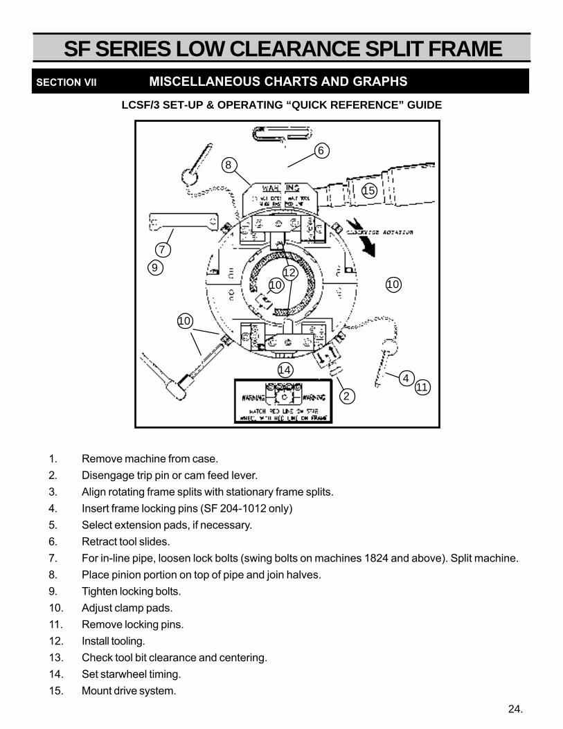
LCSF/3 SET-UP & OPERATING “QUICK REFERENCE” GUIDE
SECTION VII MISCELLANEOUS CHARTS AND GRAPHS
1. Remove machine from case.2. Disengage trip pin or cam feed lever.3. Align rotating frame splits with stationary frame splits.4. Insert frame locking pins (SF 204-1012 only)5. Select extension pads, if necessary.6. Retract tool slides.7. For in-line pipe, loosen lock bolts (swing bolts on machines 1824 and above). Split machine.8. Place pinion portion on top of pipe and join halves.9. Tighten locking bolts.10. Adjust clamp pads.11. Remove locking pins.12. Install tooling.13. Check tool bit clearance and centering.14. Set starwheel timing.15. Mount drive system.
10
7
9
86
15
10
411
2
14
1210
24.

SECTION VIII
CONSUMABLESELECTION CHART

Type
Insert Holder
Insert
HSS Severing*
Beveler
Beveler
Double Beveler
Beveler
Beveler
Double Beveler
Counterbore
Counterbore
TOOL BIT TOOLING DESCRIPTIONCOMPOSITION
TOOL BIT TOOLING DESCRIPTIONCOMPOSITION
Type
Insert Holder
Insert
HSS Severing*
Form Beveler
Form Beveler
Form Beveler
Form Beveler
Form Beveler
Form Beveler
Counterbore
Counterbore
PartNumber
T-15HSS
Coated
TOOLING CHART - LCSF STANDARD RANGE TOOLING
TOOLING CHART - LCSF EXTENDED RANGE TOOLING
Carbide
43-704-00
43-705-00
43-711-00
43-702-05
43-703-05
43-707-05
43-708-05
43-709-05
43-710-05
60-700-01
60-700-04
N/A**
‡‡
‡
‡
‡
‡
‡‡
‡
‡
**N/A = Not Applicable ‡ = Available
Self grip double sided insert holder
"Quick change" insert for servering
excellent for severing stainless steel
30° inside bevel
37.5° inside bevel
30° outside bevel
37.5° outside bevel
30° double bevel
37.5° double bevel
Recommended for LCSF 051-103
Recommended for LCSF 204-1016
**N/A = Not Applicable ‡ = Available
N/A**
‡‡
‡
‡
‡
‡
‡‡
‡
‡
PartNumber
T-15HSS
Coated Carbide
47-701-00
47-702-00
47-711-00
53-703-00
53-707-00
53-708-00
53-703-01
53-707-01
53-708-01
53-704-00
53-700-00
N/A**
‡‡
‡
‡
‡
‡
‡‡
‡‡
Self grip double sided insert holder
"Quick change" insert for servering
excellent for severing stainless steel
37.5° inside bevel
37.5° outside bevel
37.5° inside & outside bevel
30° inside bevel
30° outside bevel
37.5° inside & outside bevel
10° x 30° inside bevel
10° x 37.5° inside bevel
N/A**
‡‡
‡
‡
‡
‡
‡‡
‡‡
N/A**
‡
*T-15 HSS: A Tungsten-type High Speed Steel, very high hardness, recommended for difficult materials.
Coated: A layer of Titanium Nitride to increase cutting life and performance.
Carbide: Super-hard composite steel material offering maximum edge strength.
*T-15 HSS: A Tungsten-type High Speed Steel, very high hardness, recommended for difficult materials.
Coated: A layer of Titanium Nitride to increase cutting life and performance.
Carbide: Super-hard composite steel material offering maximum edge strength.
SECTION VIII CONSUMABLE SELECTION CHART
26

SF SERIES LOW CLEARANCE SPLIT FRAME
TROUBLE SHOOTING
SECTION IX
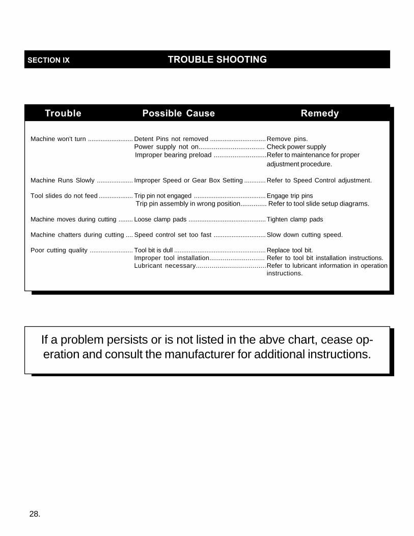
SECTION IX TROUBLE SHOOTING
Machine won't turn ......................... Detent Pins not removed ............................... Remove pins.Power supply not on................................... Check power supplyImproper bearing preload ............................Refer to maintenance for proper
adjustment procedure.
Machine Runs Slowly .................... Improper Speed or Gear Box Setting ............ Refer to Speed Control adjustment.
Tool slides do not feed ................... Trip pin not engaged ........................................ Engage trip pinsTrip pin assembly in wrong position.............. Refer to tool slide setup diagrams.
Machine moves during cutting ........ Loose clamp pads ........................................... Tighten clamp pads
Machine chatters during cutting .... Speed control set too fast ............................. Slow down cutting speed.
Poor cutting quality ........................ Tool bit is dull ................................................... Replace tool bit.Improper tool installation............................. Refer to tool bit installation instructions.Lubricant necessary....................................Refer to lubricant information in operation
instructions.
Trouble Possible Cause Remedy
If a problem persists or is not listed in the abve chart, cease op-eration and consult the manufacturer for additional instructions.
28.

SF SERIES LOW CLEARANCE SPLIT FRAME
PARTS LISTS&
EXPLODED VIEWDRAWINGS
SECTION IX

SF SERIES LOW CLEARANCE SPLIT FRAMEREF. NO. PART NO. QTY. DESCRIPTION
005 37-005-00 8 Bearing, guide wheel038 43-038-00 2 Liner100 60-100-01 1 Frame, Stationary101 60-101-01 1 Frame, Rotating102 60-102-00 1 Housing, Pinion-rear103 60-103-00 1 Gear, Drive Pinion104 60-104-01 1 Housing, Pinion105 60-105-00 8 Shaft, Eccentric107 60-107-00 1 Block, Mounting108 60-108-01 4 Pad, Clamp109 60-338-00 1 Pin, Trip122 60-122-00 6 Screw, Captive123 60-123-01 4 Screw, Clamp Pad124 60-124-00 1 Plunger, Ball125 60-125-00 1 Bearing, Pinion Rear126 60-126-00 1 Bearing, Pnion Front127 60-408-00 Extension Leg set to
cover entire clampingrange
128 60-128-00 8 spacer, Frame Bearing133 60-133-00 8 Nut, Push 5/16" set160 60-160-00 1 Ring, Retaining161 60-161-00 1 Ring, Retaining166 60-166-01 4 Guard, Chip179 60-179-00 4 Frame Plug
FASTENERS:1 90-065-53 8 5/16" an washer2 90-065-03 8 5/16-18 Nylok Washer3 90-060-08 4 5/16-18 x 7/8" shcs4 90-064-03 4 5/16-18 x 3/8" sss5 90-060-07 3 5/16-18 x 3/4" shcs6 90-050-03 3 1/4-20 x 3/8" Shcs7 90-042-03 4 10-24 x 3/8 bhcs8 90-056-03 6 1/4 x 1/2 dowel pin9 90-056-05 4 1/4 x 3/8 dowel pin10 90-026-55 1 1/8 x 1/2 roll pin11 90-060-20 2 5/16-18 x 2 shcs12 90-050-20 4 1/4-20 x 2 shcs13 90-076-07 2 3/8" x 3/4" dowel pin14 90-060-07 2 5/16-18 x 3/4" shcs15 90-055-04 1 1/4-20 jam nut16 90-900-63 1 Knob, Push17 90-060-05 8 5/16-18 x 1/2" shcs
Not Shown43-053-00 1 Storage case43-054-00 1 Insert, foam90-059-12 4 1/4-20 x 1/2" insert90-069-12 9 5/16-18 x 1/2" insert90-219-75 4 3/4-10 x 3/4 insert60-180-00 1 Decal, Slide Warning60-181-00 1 Decal, Gear Warning60-209-00 1 Seal, Pinion Housing59-117-00 1 Decal, Open Machine
REF. NO. PART NO. QTY. DESCRIPTION
005 37-005-00 6 Bearing, guide wheel038 43-038-00 2 Liner100 60-100-01 1 Frame, Stationary101 60-101-01 1 Frame, Rotating102 60-102-00 1 Housing, Pinion-rear103 60-103-00 1 Gear, Drive Pinion104 60-104-01 1 Housing, Pinion105 60-105-00 6 Shaft, Eccentric107 60-107-00 1 Block, Mounting108 60-108-01 3 Pad, Clamp109 60-338-00 1 Pin, Trip122 60-122-00 6 Screw, Captive123 60-123-01 3 Screw, Clamp Pad124 60-124-00 1 Plunger, Ball125 60-125-00 1 Bearing, Pinion Rear126 60-126-00 1 Bearing, Pnion Front127 60-408-00 Extension Leg set to
cover entire clampingrange
128 60-128-00 6 spacer, Frame Bearing133 60-133-00 6 Nut, Push 5/16" set160 60-160-00 1 Ring, Retaining161 60-161-00 3 Ring, Retaining166 60-166-01 3 Guard, Chip179 60-179-00 4 Frame Plug
FASTENERS:1 90-065-53 6 5/16" an washer2 90-065-03 6 5/16-18 Nylok Washer3 90-060-08 3 5/16-18 x 7/8" shcs4 90-064-03 3 5/16-18 x 3/8" sss5 90-060-07 3 5/16-18 x 3/4" shcs6 90-050-03 3 1/4-20 x 3/8" Shcs7 90-042-03 3 10-24 x 3/8 bhcs8 90-056-03 3 1/4 x 1/2 dowel pin9 90-056-05 6 1/4 x 3/8 dowel pin10 90-026-55 1 1/8 x 1/2 roll pin11 90-060-20 2 5/16-18 x 2 shcs12 90-050-20 4 1/4-20 x 2 shcs13 90-076-07 2 3/8" x 3/4" dowel pin14 90-060-07 2 5/16-18 x 3/4" shcs15 90-055-04 1 1/4-20 jam nut16 90-900-63 1 Knob, Push17 90-060-05 6 5/16-18 x 1/2" shcs
Not Shown43-053-00 1 Storage case43-054-00 1 Insert, foam90-059-12 4 1/4-20 x 1/2" insert90-069-12 9 5/16-18 x 1/2" insert90-219-75 3 3/4-10 x 3/4 insert60-180-00 1 Decal, Slide Warning60-181-00- 1 Decal, Gear Warning60-209-00 1 Seal, Pinion Housing59-117-00 1 Decal, Open Machine
60-000-01 LCSF 051/3 60-000-02 LCSF 102/3
30.
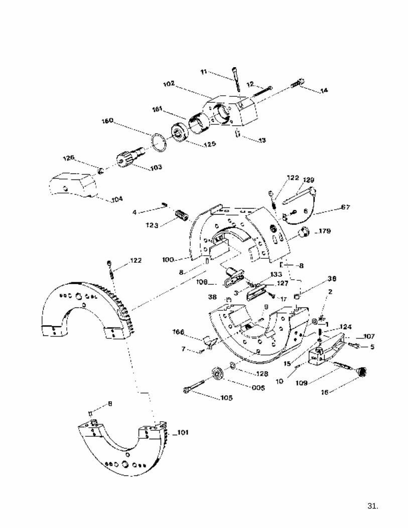
31.

SF SERIES LOW CLEARANCE SPLIT FRAME
REF. NO. PART NO. QTY. DESCRIPTION
005 37-005-00 14 Bearing, guide wheel038 43-038-00 2 Liner067 46-067-00 2 Pin Chain100 60-100-04 1 Frame, Stationary 4"101 60-101-04 1 Frame, Rotating 4"102 60-102-00 1 Housing, Pinion-rear103 60-103-00 1 Gear, Drive Pinion104 60-104-01 1 Housing, Pinion105 60-105-00 14 Shaft, Eccentric107 60-107-00 1 Block, Mounting108 60-108-04 4 Pad, Clamp109 60-338-00 1 Pin, Trip122 60-122-00 6 Screw, Captive123 60-123-04 4 Screw, Clamp Pad124 60-124-00 1 Plunger, Ball125 60-125-00 1 Bearing, Pinion Rear126 60-126-00 1 Bearing, Pnion Front127 60-408-00 Extension Leg set to
cover entire clampingrange
128 60-128-00 14 spacer, Frame Bearing129 60-129-00 2 Frame lock pin133 60-133-00 8 Nut, Push 5/16" set160 60-160-00 1 Ring, Retaining161 60-161-00 1 Ring, Retaining166 60-166-04 4 Guard, Chip179 60-179-00 4 Frame Plug
FASTENERS:1 90-065-53 14 5/16" an washer2 90-065-03 14 5/16-18 Nylok Washer3 90-060-08 4 5/16-18 x 7/8" shcs4 90-064-03 4 5/16-18 x 3/8" sss5 90-060-07 3 5/16-18 x 3/4" shcs6 90-050-03 2 1/4-20 x 3/8" Shcs7 90-042-03 4 10-24 x 3/8 bhcs8 90-056-03 6 1/4 x 1/2 dowel pin9 90-056-05 3 1/4 x 3/8 dowel pin10 90-026-55 1 1/8 x 1/2 roll pin11 90-060-20 2 5/16-18 x 2 shcs12 90-050-20 4 1/4-20 x 2 shcs13 90-076-07 2 3/8" x 3/4" dowel pin14 90-060-07 2 5/16-18 x 3/4" shcs15 90-055-04 1 1/4-20 jam nut16 90-900-63 1 Knob, Push17 90-060-05 8 5/16-18 x 1/2" shcs
Not Shown43-053-00 1 Storage case43-054-00 1 Insert, foam90-059-12 4 1/4-20 x 1/2" insert90-069-12 9 5/16-18 x 1/2" insert90-219-75 4 3/4-10 x 3/4 insert60-180-00 1 Decal, Slide Warning60-181-00- 1 Decal, Gear Warning60-209-00 1 Seal, Pinion Housing59-117-00 1 Decal, Open Machine
REF. NO. PART NO. QTY. DESCRIPTION
005 37-005-00 8 Bearing, guide wheel038 43-038-00 2 Liner067 46-067-00 2 Pin Chain100 60-100-03 1 Frame, Stationary 1"101 60-101-03 1 Frame, Rotating 1"102 60-102-00 1 Housing, Pinion-rear103 60-103-00 1 Gear, Drive Pinion104 60-104-01 1 Housing, Pinion105 60-105-00 8 Shaft, Eccentric107 60-107-00 1 Block, Mounting108 60-108-01 4 Pad, Clamp109 60-338-00 1 Pin, Trip122 60-122-00 6 Screw, Captive123 60-123-01 4 Screw, Clamp Pad124 60-124-00 1 Plunger, Ball125 60-125-00 1 Bearing, Pinion Rear126 60-126-00 1 Bearing, Pnion Front127 60-408-00 Extension Leg set to
cover entire clampingrange
128 60-128-00 8 spacer, Frame Bearing129 60-129-00 2 Frame lock pin133 60-133-00 6 Nut, Push 5/16" set160 60-160-00 1 Ring, Retaining161 60-161-00 3 Ring, Retaining166 60-166-01 3 Guard, Chip179 60-179-00 4 Frame Plug
FASTENERS:1 90-065-53 8 5/16" an washer2 90-065-03 8 5/16-18 Nylok Washer3 90-060-08 3 5/16-18 x 7/8" shcs4 90-064-03 4 5/16-18 x 3/8" sss5 90-060-07 4 5/16-18 x 3/4" shcs6 90-050-03 3 1/4-20 x 3/8" Shcs7 90-042-03 4 10-24 x 3/8 bhcs8 90-056-03 6 1/4 x 1/2 dowel pin9 90-056-05 4 1/4 x 3/8 dowel pin10 90-026-55 1 1/8 x 1/2 roll pin11 90-060-20 2 5/16-18 x 2 shcs12 90-050-20 4 1/4-20 x 2 shcs13 90-076-07 2 3/8" x 3/4" dowel pin14 90-060-07 2 5/16-18 x 3/4" shcs15 90-055-04 1 1/4-20 jam nut16 90-900-63 1 Knob, Push17 90-060-05 8 5/16-18 x 1/2" shcs
Not Shown43-053-00 1 Storage case43-054-00 1 Insert, foam90-059-12 4 1/4-20 x 1/2" insert90-069-12 9 5/16-18 x 1/2" insert90-219-75 3 3/4-10 x 3/4 insert60-180-00 1 Decal, Slide Warning60-181-00- 1 Decal, Gear Warning60-209-00 1 Seal, Pinion Housing59-117-00 1 Decal, Open Machine
60-000-03 LCSF 103/3 60-000-04 LCSF 204/3
32.
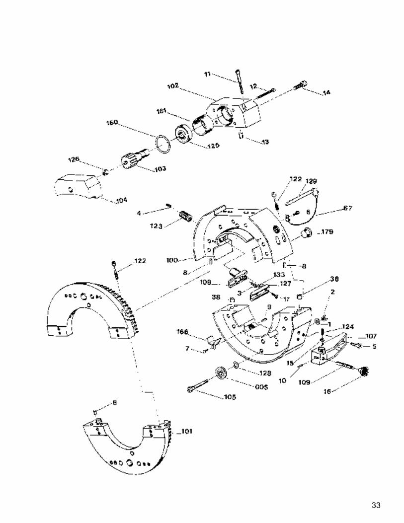
33

SF SERIES LOW CLEARANCE SPLIT FRAME
REF. NO. PART NO. QTY. DESCRIPTION005 37-005-00 16 Bearing, guide wheel038 43-038-00 2 Liner067 46-067-00 2 Pin Chain100 60-100-08 1 Frame, Stationary 8"101 60-101-08 1 Frame, Rotating 8"102 60-102-00 1 Housing, Pinion-rear103 60-103-00 1 Gear, Drive Pinion104 60-104-01 1 Housing, Pinion105 60-105-00 16 Shaft, Eccentric107 60-107-00 1 Block, Mounting108 60-108-04 4 Pad, Clamp109 60-338-00 1 Pin, Trip122 60-122-00 6 Screw, Captive123 60-123-04 4 Screw, Clamp Pad124 60-124-00 1 Plunger, Ball125 60-125-00 1 Bearing, Pinion Rear126 60-126-00 1 Bearing, Pnion Front127 60-408-54 Extension Leg set to
cover entire clampingrange
128 60-128-00 16 Spacer, Frame Bearing129 60-129-00 2 Pin, Frame Lock133 60-133-00 8 Nut, Push 5/16" set160 60-160-00 1 Ring, Retaining161 60-161-00 1 Ring, Retaining166 60-166-04 4 Guard, Chip179 60-179-00 4 Frame Plug
FASTENERS:1 90-065-53 16 5/16" an washer2 90-065-03 16 5/16-18 Nylok Washer3 90-060-08 4 5/16-18 x 7/8" shcs4 90-064-03 4 5/16-18 x 3/8" sss5 90-060-07 3 5/16-18 x 3/4" shcs6 90-050-03 2 1/4-20 x 3/8" Shcs7 90-042-03 4 10-24 x 3/8 bhcs8 90-056-03 6 1/4 x 1/2 dowel pin9 90-056-05 4 1/4 x 3/8 dowel pin10 90-026-55 1 1/8 x 1/2 roll pin11 90-060-20 2 5/16-18 x 2 shcs12 90-050-20 4 1/4-20 x 2 shcs13 90-076-07 2 3/8" x 3/4" dowel pin14 90-060-07 2 5/16-18 x 3/4" shcs15 90-055-04 1 1/4-20 jam nut16 90-900-63 1 Knob, Push17 90-060-05 8 5/16-18 x 1/2" shcs
Not Shown43-053-00 1 Storage case43-054-00 1 Insert, foam90-059-12 4 1/4-20 x 1/2" insert90-069-12 9 5/16-18 x 1/2" insert90-219-75 4 3/4-10 x 3/4 insert60-180-00 1 Decal, Slide Warning60-181-00- 1 Decal, Gear Warning60-209-00 1 Seal, Pinion Housing59-117-00 1 Decal, Open Machine
REF. NO. PART NO. QTY. DESCRIPTION005 37-005-00 14 Bearing, guide wheel038 43-038-00 2 Liner067 46-067-00 2 Pin Chain100 60-100-06 1 Frame, Stationary 6"101 60-101-06 1 Frame, Rotating 6"102 60-102-00 1 Housing, Pinion-rear103 60-103-00 1 Gear, Drive Pinion104 60-104-01 1 Housing, Pinion105 60-105-00 14 Shaft, Eccentric107 60-107-00 1 Block, Mounting108 60-108-01 4 Pad, Clamp109 60-338-00 1 Pin, Trip122 60-122-00 6 Screw, Captive123 60-123-04 4 Screw, Clamp Pad124 60-124-00 1 Plunger, Ball125 60-125-00 1 Bearing, Pinion Rear126 60-126-00 1 Bearing, Pnion Front127 60-408-50 Extension Leg set to
cover entire clampingrange
128 60-128-00 6 Spacer, Frame Bearing129 60-129-00 2 Pin, Frame Lock133 60-133-00 8 Nut, Push 5/16" set160 60-160-00 1 Ring, Retaining161 60-161-00 4 Ring, Retaining166 60-166-04 4 Guard, Chip179 60-179-00 4 Frame Plug
FASTENERS:1 90-065-53 14 5/16" an washer2 90-065-03 14 5/16-18 Nylok Washer3 90-060-08 4 5/16-18 x 7/8" shcs4 90-064-03 4 5/16-18 x 3/8" sss5 90-060-07 3 5/16-18 x 3/4" shcs6 90-050-03 2 1/4-20 x 3/8" Shcs7 90-042-03 4 10-24 x 3/8 bhcs8 90-056-03 6 1/4 x 1/2 dowel pin9 90-056-05 4 1/4 x 3/8 dowel pin10 90-026-55 1 1/8 x 1/2 roll pin11 90-060-20 2 5/16-18 x 2 shcs12 90-050-20 4 1/4-20 x 2 shcs13 90-076-07 2 3/8" x 3/4" dowel pin14 90-060-07 2 5/16-18 x 3/4" shcs15 90-055-04 1 1/4-20 jam nut16 90-900-63 1 Knob, Push17 90-060-05 8 5/16-18 x 1/2" shcs
Not Shown43-053-00 1 Storage case43-054-00 1 Insert, foam90-059-12 4 1/4-20 x 1/2" insert90-069-12 9 5/16-18 x 1/2" insert90-219-75 3 3/4-10 x 3/4 insert60-180-00 1 Decal, Slide Warning60-181-00- 1 Decal, Gear Warning60-209-00 1 Seal, Pinion Housing59-117-00 1 Decal, Open Machine
60-000-06 LCSF 206/3 60-000-08 LCSF 408/3
34
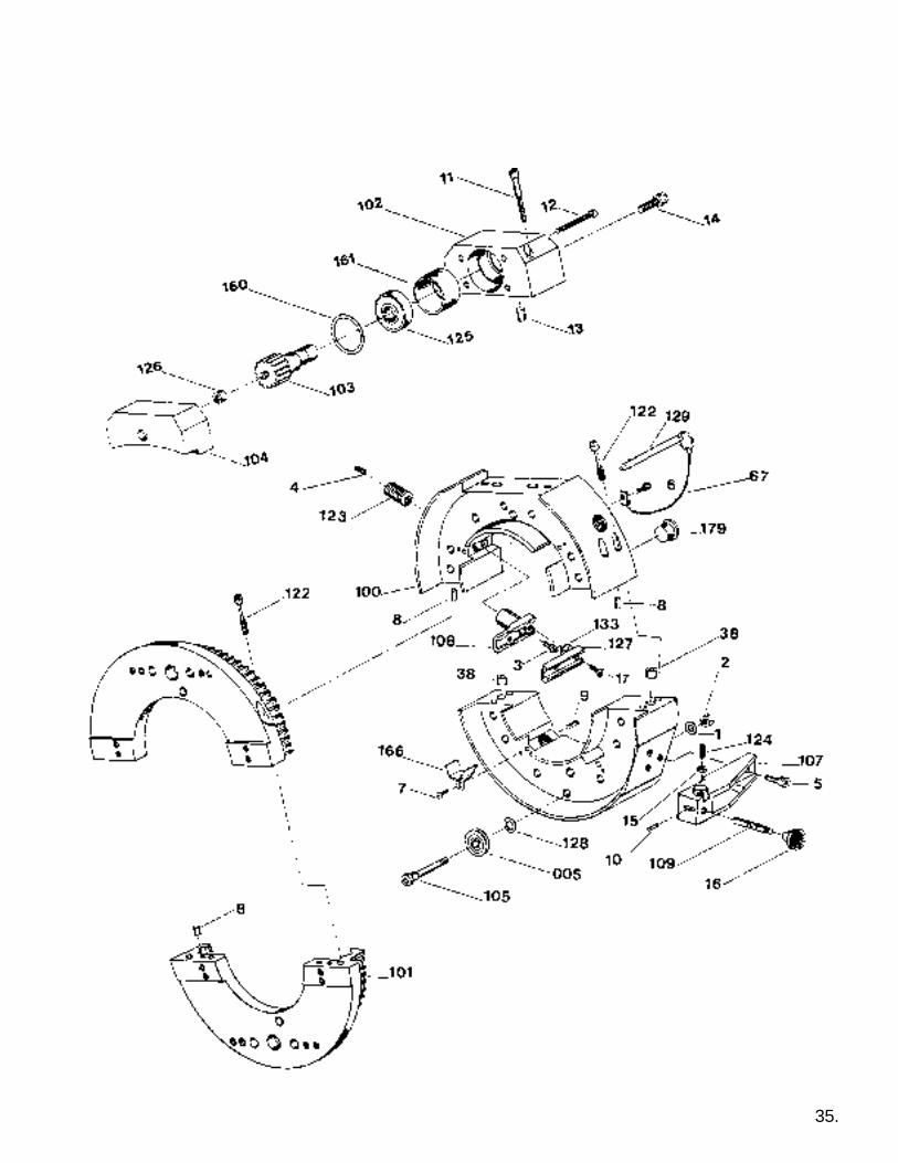
35.

SF SERIES LOW CLEARANCE SPLIT FRAME
REF. NO. PART NO. QTY. DESCRIPTION
005 37-005-00 22 Bearing, guide wheel038 43-038-00 2 Liner067 46-067-00 2 Pin Chain100 60-100-12 1 Frame, Stationary 12"101 60-101-12 1 Frame, Rotating 12"102 60-102-00 1 Housing, Pinion-rear103 60-103-00 1 Gear, Drive Pinion104 60-104-01 1 Housing, Pinion105 60-105-00 22 Shaft, Eccentric107 60-107-00 1 Block, Mounting108 60-108-04 4 Pad, Clamp109 60-338-00 1 Pin, Trip122 60-122-00 6 Screw, Captive123 60-123-10 4 Screw, Clamp Pad124 60-124-00 1 Plunger, Ball125 60-125-00 1 Bearing, Pinion Rear126 60-126-00 1 Bearing, Pnion Front127 60-408-51 Extension Leg set to
cover entire clampingrange
128 60-128-00 22 spacer, Frame Bearing129 60-129-00 2 Pin, Frame Lock133 60-133-00 8 Nut, Push 5/16" set160 60-160-00 1 Ring, Retaining161 60-161-00 1 Ring, Retaining166 60-166-04 4 Guard, Chip179 60-179-00 4 Frame Plug
FASTENERS:1 90-065-53 22 5/16" an washer2 90-065-03 22 5/16-18 Nylok Washer3 90-060-08 4 5/16-18 x 7/8" shcs4 90-064-03 4 5/16-18 x 3/8" sss5 90-060-07 3 5/16-18 x 3/4" shcs6 90-050-03 2 1/4-20 x 3/8" Shcs7 90-042-03 4 10-24 x 3/8 bhcs8 90-056-03 6 1/4 x 1/2 dowel pin9 90-056-05 4 1/4 x 3/8 dowel pin10 90-026-55 1 1/8 x 1/2 roll pin11 90-060-20 2 5/16-18 x 2 shcs12 90-050-20 4 1/4-20 x 2 shcs13 90-076-07 2 3/8" x 3/4" dowel pin14 90-060-07 2 5/16-18 x 3/4" shcs15 90-055-04 1 1/4-20 jam nut16 90-900-63 1 Knob, Push17 90-060-05 8 5/16-18 x 1/2" shcs
Not Shown43-053-00 1 Storage case43-054-00 1 Insert, foam90-059-12 4 1/4-20 x 1/2" insert90-069-12 9 5/16-18 x 1/2" insert90-219-75 4 3/4-10 x 3/4 insert60-180-00 1 Decal, Slide Warning60-181-00 1 Decal, Gear Warning60-209-00 1 Seal, Pinion Housing59-117-00 1 Decal, Open Machine
REF. NO. PART NO. QTY. DESCRIPTION
005 37-005-00 22 Bearing, guide wheel038 43-038-00 2 Liner067 46-067-00 2 Pin Chain100 60-100-10 1 Frame, Stationary 10"101 60-101-10 1 Frame, Rotating 10"102 60-102-00 1 Housing, Pinion-rear103 60-103-00 1 Gear, Drive Pinion104 60-104-01 1 Housing, Pinion105 60-105-00 22 Shaft, Eccentric107 60-107-00 1 Block, Mounting108 60-108-01 4 Pad, Clamp109 60-338-00 1 Pin, Trip122 60-122-00 6 Screw, Captive123 60-123-10 4 Screw, Clamp Pad124 60-124-00 1 Plunger, Ball125 60-125-00 1 Bearing, Pinion Rear126 60-126-00 1 Bearing, Pnion Front127 60-408-54 Extension Leg set to
cover entire clampingrange
128 60-128-00 22 spacer, Frame Bearing129 60-129-00 2 Pin, Frame Lock133 60-133-00 8 Nut, Push 5/16" set160 60-160-00 1 Ring, Retaining161 60-161-00 1 Ring, Retaining166 60-166-04 4 Guard, Chip179 60-179-00 4 Frame Plug
FASTENERS:1 90-065-53 22 5/16" an washer2 90-065-03 22 5/16-18 Nylok Washer3 90-060-08 4 5/16-18 x 7/8" shcs4 90-064-03 4 5/16-18 x 3/8" sss5 90-060-07 3 5/16-18 x 3/4" shcs6 90-050-03 2 1/4-20 x 3/8" Shcs7 90-042-03 4 10-24 x 3/8 bhcs8 90-056-03 6 1/4 x 1/2 dowel pin9 90-056-05 4 1/4 x 3/8 dowel pin10 90-026-55 1 1/8 x 1/2 roll pin11 90-060-20 2 5/16-18 x 2 shcs12 90-050-20 4 1/4-20 x 2 shcs13 90-076-07 2 3/8" x 3/4" dowel pin14 90-060-07 2 5/16-18 x 3/4" shcs15 90-055-04 1 1/4-20 jam nut16 90-900-63 1 Knob, Push17 90-060-05 8 5/16-18 x 1/2" shcs
Not Shown43-053-00 1 Storage case43-054-00 1 Insert, foam90-059-12 4 1/4-20 x 1/2" insert90-069-12 9 5/16-18 x 1/2" insert90-219-75 3 3/4-10 x 3/4 insert60-180-00 1 Decal, Slide Warning60-181-00 1 Decal, Gear Warning60-209-00 1 Seal, Pinion Housing59-117-00 1 Decal, Open Machine
60-000-10 LCSF 610/3 60-000-12 LCSF 612/3
36.
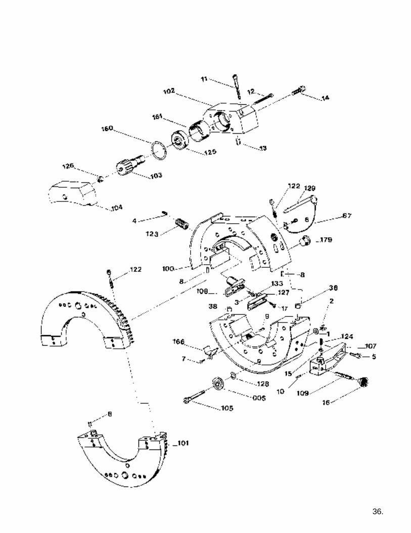
36.

SF SERIES LOW CLEARANCE SPLIT FRAMEREF. NO. PART NO. QTY. DESCRIPTION
005 37-005-00 30 Bearing, guide wheel038 60-208-00 2 Bushing, Jig067 46-067-00 2 Pin Chain100 60-100-16 1 Frame, Stationary 16"101 60-101-16 1 Frame, Rotating 16"102 60-102-00 1 Housing, Pinion-rear103 60-103-00 1 Gear, Drive Pinion104 60-104-01 1 Housing, Pinion105 60-105-00 30 Shaft, Eccentric107 60-107-00 1 Block, Mounting108 60-108-04 4 Pad, Clamp109 60-338-00 1 Pin, Trip122 60-122-00 6 Screw, Captive123 60-123-10 4 Screw, Clamp Pad124 60-124-00 1 Plunger, Ball125 60-125-00 1 Bearing, Pinion Rear126 60-126-00 1 Bearing, Pnion Front127 60-408-52 Extension Leg set to
cover entire clampingrange
128 60-128-00 30 spacer, Frame Bearing129 60-129-00 2 Pin, Frame Lock133 60-133-00 8 Nut, Push 5/16" set160 60-160-00 1 Ring, Retaining161 60-161-00 1 Ring, Retaining166 60-166-04 4 Guard, Chip179 60-179-00 4 Frame Plug
FASTENERS:1 90-065-53 30 5/16" an washer2 90-065-03 30 5/16-18 Nylok Washer3 90-060-08 4 5/16-18 x 7/8" shcs4 90-064-03 4 5/16-18 x 3/8" sss5 90-060-07 3 5/16-18 x 3/4" shcs6 90-050-03 2 1/4-20 x 3/8" Shcs7 90-042-03 4 10-24 x 3/8 bhcs8 90-056-03 6 1/4 x 1/2 dowel pin9 90-056-05 4 1/4 x 3/8 dowel pin10 90-026-55 1 1/8 x 1/2 roll pin11 90-060-20 2 5/16-18 x 2 shcs12 90-050-20 4 1/4-20 x 2 shcs13 90-076-07 2 3/8" x 3/4" dowel pin14 90-060-07 2 5/16-18 x 3/4" shcs15 90-055-04 1 1/4-20 jam nut16 90-900-63 1 Knob, Push17 90-060-05 8 5/16-18 x 1/2" shcs
Not Shown43-053-00 1 Storage case43-054-00 1 Insert, foam90-059-12 4 1/4-20 x 1/2" insert90-069-12 9 5/16-18 x 1/2" insert90-219-75 4 3/4-10 x 3/4 insert60-180-00 1 Decal, Slide Warning60-181-00- 1 Decal, Gear Warning59-117-00 1 Decal, Open Machine
REF. NO. PART NO. QTY. DESCRIPTION
005 37-005-00 22 Bearing, guide wheel038 43-038-00 2 Liner067 46-067-00 2 Pin Chain100 60-100-14 1 Frame, Stationary 14"101 60-101-14 1 Frame, Rotating 14"102 60-102-00 1 Housing, Pinion-rear103 60-103-00 1 Gear, Drive Pinion104 60-104-01 1 Housing, Pinion105 60-105-00 22 Shaft, Eccentric107 60-107-00 1 Block, Mounting108 60-108-10 4 Pad, Clamp109 60-338-00 1 Pin, Trip122 60-122-00 6 Screw, Captive123 60-123-10 4 Screw, Clamp Pad124 60-124-00 1 Plunger, Ball125 60-125-00 1 Bearing, Pinion Rear126 60-126-00 1 Bearing, Pnion Front127 60-408-53 Extension Leg set to
cover entire clampingrange
128 60-128-00 22 spacer, Frame Bearing129 60-129-00 2 Pin, Frame Lock133 60-133-00 8 Nut, Push 5/16" set160 60-160-00 1 Ring, Retaining161 60-161-00 1 Ring, Retaining166 60-166-04 4 Guard, Chip179 60-179-00 4 Frame Plug
FASTENERS:1 90-065-53 22 5/16" an washer2 90-065-03 22 5/16-18 Nylok Washer3 90-060-08 4 5/16-18 x 7/8" shcs4 90-064-03 4 5/16-18 x 3/8" sss5 90-060-07 3 5/16-18 x 3/4" shcs6 90-050-03 2 1/4-20 x 3/8" Shcs7 90-042-03 4 10-24 x 3/8 bhcs8 90-056-03 6 1/4 x 1/2 dowel pin9 90-056-05 4 1/4 x 3/8 dowel pin10 90-026-55 1 1/8 x 1/2 roll pin11 90-060-20 2 5/16-18 x 2 shcs12 90-050-20 4 1/4-20 x 2 shcs13 90-076-07 2 3/8" x 3/4" dowel pin14 90-060-07 2 5/16-18 x 3/4" shcs15 90-055-04 1 1/4-20 jam nut16 90-900-63 1 Knob, Push17 90-060-05 8 5/16-18 x 1/2" shcs
Not Shown43-053-00 1 Storage case43-054-00 1 Insert, foam90-059-12 4 1/4-20 x 1/2" insert90-069-12 9 5/16-18 x 1/2" insert90-219-75 3 3/4-10 x 3/4 insert60-180-00 1 Decal, Slide Warning60-181-00 1 Decal, Gear Warning59-117-00 1 Decal, Open Machine
60-000-14 LCSF 814/3 60-000-16 LCSF 1016/3
37.
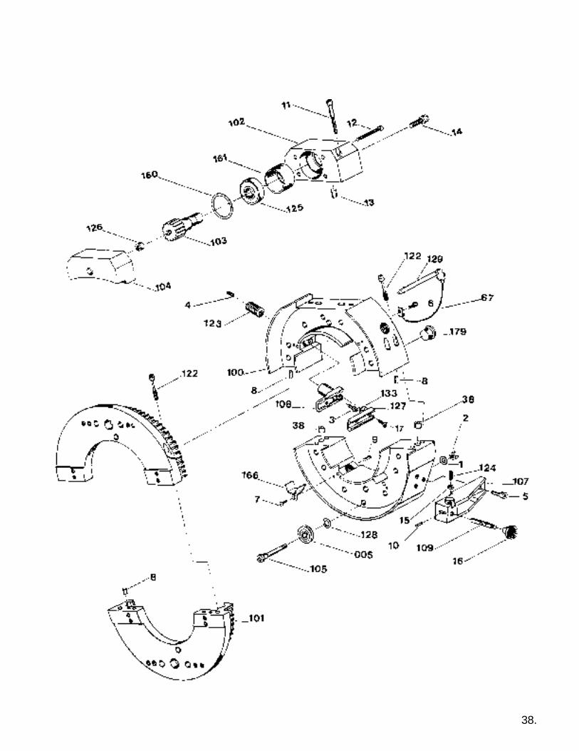
38.

SF SERIES LOW CLEARANCE SPLIT FRAME
REF. NO. PART NO. QTY. DESCRIPTION
005 37-005-00 30 Bearing, guide wheel038 43-038-00 2 Liner067 46-067-00 2 Pin Chain100 60-100-20 1 Frame, Stationary 20"101 60-101-20 1 Frame, Rotating 20"102 60-102-00 1 Housing, Pinion-rear103 60-103-00 1 Gear, Drive Pinion104 60-104-20 1 Housing, Pinion105 60-105-00 30 Shaft, Eccentric107 60-107-00 1 Block, Mounting108 60-108-01 4 Pad, Clamp109 60-338-00 1 Pin, Trip122 60-122-00 6 Screw, Captive123 60-123-10 4 Screw, Clamp Pad124 60-124-00 1 Plunger, Ball125 60-125-00 1 Bearing, Pinion Rear126 60-126-00 1 Bearing, Pnion Front127 60-408-51 Extension Leg set to
cover entire clampingrange
128 60-128-00 30 spacer, Frame Bearing129 60-129-00 2 Pin, Frame Lock133 60-133-00 8 Nut, Push 5/16" set160 60-160-00 1 Ring, Retaining161 60-161-00 1 Ring, Retaining166 60-166-04 4 Guard, Chip179 60-179-00 4 Frame Plug
FASTENERS:1 90-065-53 22 5/16" an washer2 90-065-03 22 5/16-18 Nylok Washer3 90-060-08 4 5/16-18 x 7/8" shcs4 90-064-03 4 5/16-18 x 3/8" sss5 90-060-07 3 5/16-18 x 3/4" shcs6 90-050-03 2 1/4-20 x 3/8" Shcs7 90-042-03 4 10-24 x 3/8 bhcs8 90-056-03 6 1/4 x 1/2 dowel pin9 90-056-05 4 1/4 x 3/8 dowel pin10 90-026-55 1 1/8 x 1/2 roll pin11 90-060-20 2 5/16-18 x 2 shcs12 90-050-20 4 1/4-20 x 2 shcs13 90-076-07 2 3/8" x 3/4" dowel pin14 90-060-07 2 5/16-18 x 3/4" shcs15 90-055-04 1 1/4-20 jam nut16 90-900-63 1 Knob, Push17 90-060-05 8 5/16-18 x 1/2" shcs
Not Shown43-053-00 1 Storage case43-054-00 1 Insert, foam90-059-12 4 1/4-20 x 1/2" insert90-069-12 9 5/16-18 x 1/2" insert90-219-75 3 3/4-10 x 3/4 insert60-180-00 1 Decal, Slide Warning60-181-00 1 Decal, Gear Warning60-209-00 1 Pinion seal59-117-00 1 Decal, Open Machine
60-000-20 LCSF 1420/3
39.

40.

SF SERIES LOW CLEARANCE SPLIT FRAME
REF. NO. PART NO. QTY. DESCRIPTION
249 60-249-24 1 Ring, Stationary352 60-352-24 1 Ring, Rotating254 60-254-00 2 Latch, Slotted255 60-255-00 2 Latch, Pivot256 60-256-00 32 Eccentric Shaft257 60-257-00 32 Spacer, Bearing258 60-258-00 8 Screw, Clamp pad259 60-259-00 2 Screw, Captivated260 60-260-00 32 Bearing, Guide Wheel262 60-262-00 2 Bushing drill263 60-263-00 2 Bolt, Swing264 60-264-00 4 Pin, Detent265 59-117-00 1 Label, Open Machine266 60-180-00 1 Decal, Slide Warning150 22-150-00 2 Nut, 1/2-13" flange108 60-108-10 8 Pad, Clamp207 60-207-00 2 Screw, Captivated102 60-102-00 1 Housing, Pinion Rear103 60-103-01 1 Gear, Pinion104 60-104-36 1 Housing, Pinion Front182 60-182-01 1 Pinion Drive125 60-125-00 1 Bearing, Pinion Rear126 60-126-00 1 Bearing, Pinion Front127 60-408-49 Extension Leg set to
cover entire clampingrange
133 60-133-00 16 Nut, Push 5/16160 60-160-00 1 Ring, Retaining161 60-161-00 1 Ring, Retaining209 60-209-00 1 Seal, Pinion
FASTENERS:2 90-060-08 8 SHCS, 5/16-18x7/86 90-060-02 2 5/16-18 x 2" shcs7 90-050-17 4 1/4-20 x 1-3/4" shcs9 90-056-06 8 1/4 x 5/8" Dowel Pin11 90-056-05 4 1/4 x 3/8 dowel pin12 90-075-05 2 Nylock nut13 90-050-20 4 1/4-20 x 2 shcs14 90-076-07 2 3/8" x 3/4" dowel pin15 90-097-65 2 5/16-18 x 3/4" shcs16 90-055-04 1 1/4-20 jam nut17 90-060-05 8 5/16-18 x 1/2" shcs18 90-060-07 2 5/16-18 x 3/4" shcs
Not Shown
59-117-00 1 Decal, Open Machine90-099-91 1 Eye Bolt 1/2-1360-324-00 1 Serial Tag
60-000-24 LCSF 1824/3 60-000-28 LCSF 2228/3
41.
REF. NO. PART NO. QTY. DESCRIPTION
249 60-249-28 1 Ring, Stationary352 60-352-24 1 Ring, Rotating254 60-254-00 2 Latch, Slotted255 60-255-00 2 Latch, Pivot256 60-256-00 32 Eccentric Shaft257 60-257-00 32 Spacer, Bearing258 60-258-00 8 Screw, Clamp pad259 60-259-00 2 Screw, Captivated260 60-260-00 32 Bearing, Guide Wheel262 60-262-00 2 Bushing drill263 60-263-00 2 Bolt, Swing264 60-264-00 4 Pin, Detent265 59-117-00 1 Label, Open Machine266 60-180-00 1 Decal, Slide Warning150 22-150-00 2 Nut, 1/2-13" flange108 60-108-10 8 Pad, Clamp207 60-207-00 2 Screw, Captivated102 60-102-00 1 Housing, Pinion Rear103 60-103-01 1 Gear, Pinion104 60-104-36 1 Housing, Pinion Front182 60-182-01 1 Pinion Drive125 60-125-00 1 Bearing, Pinion Rear126 60-126-00 1 Bearing, Pinion Front127 60-408-49 Extension Leg set to
cover entire clampingrange
133 60-133-00 16 Nut, Push 5/16160 60-160-00 1 Ring, Retaining161 60-161-00 1 Ring, Retaining209 60-209-00 1 Seal, Pinion
FASTENERS:2 90-060-08 8 SHCS, 5/16-18x7/86 90-060-02 2 5/16-18 x 2" shcs7 90-050-17 4 1/4-20 x 1-3/4" shcs9 90-056-06 8 1/4 x 5/8" Dowel Pin11 90-056-05 4 1/4 x 3/8 dowel pin12 90-075-05 2 Nylock nut13 90-050-20 4 1/4-20 x 2 shcs14 90-076-07 2 3/8" x 3/4" dowel pin15 90-097-65 2 5/16-18 x 3/4" shcs16 90-055-04 1 1/4-20 jam nut17 90-060-05 8 5/16-18 x 1/2" shcs18 90-060-07 2 5/16-18 x 3/4" shcs
Not Shown
59-117-00 1 Decal, Open Machine90-099-91 1 Eye Bolt 1/2-1360-324-00 1 Serial Tag
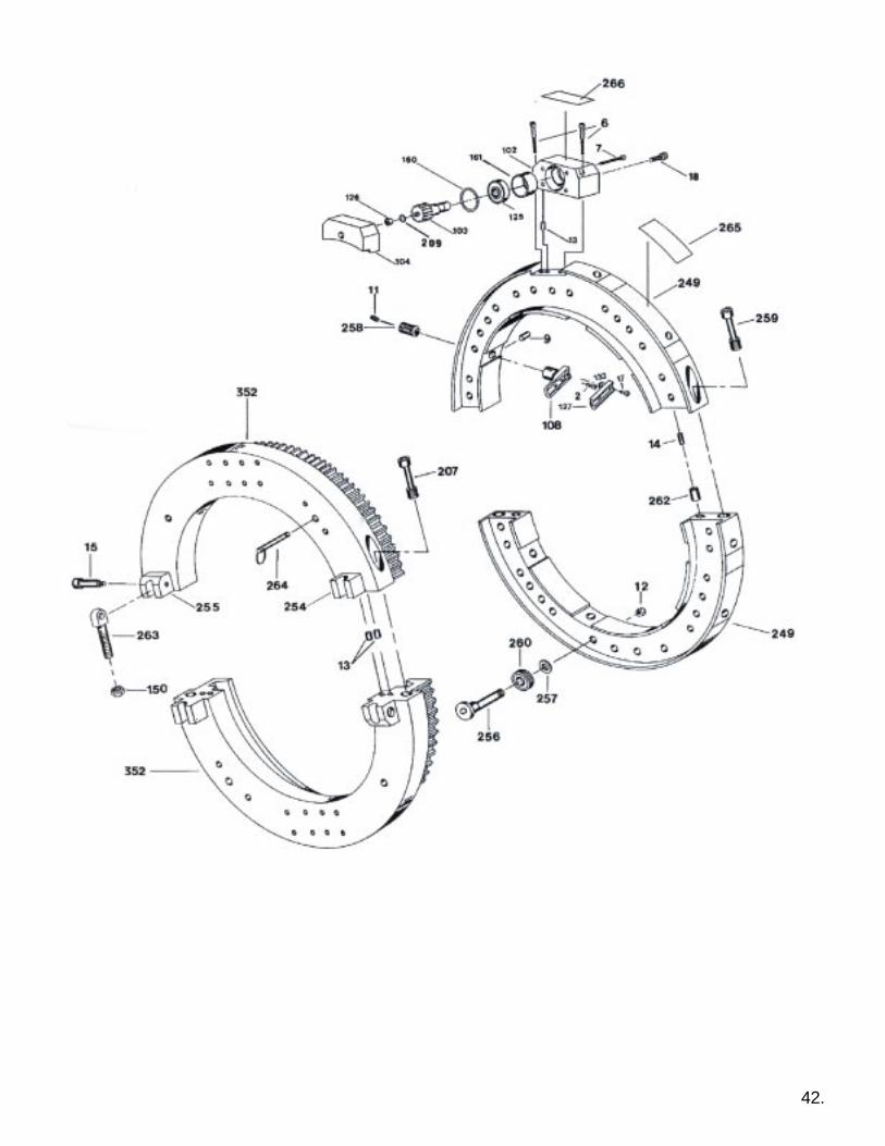
42.

SF SERIES LOW CLEARANCE SPLIT FRAME
60-000-32 LCSF 2632/3 60-000-36 LCSF 3036/3
43.
REF. NO. PART NO. QTY. DESCRIPTION
249 60-249-32 1 Ring, Stationary352 60-352-32 1 Ring, Rotating254 60-254-00 2 Latch, Slotted255 60-255-00 2 Latch, Pivot256 60-256-00 32 Eccentric Shaft257 60-257-00 32 Spacer, Bearing258 60-258-00 8 Screw, Clamp pad259 60-259-00 2 Screw, Captivated260 60-260-00 32 Bearing, Guide Wheel262 60-262-00 2 Bushing drill263 60-263-00 2 Bolt, Swing264 60-264-00 4 Pin, Detent265 59-117-00 1 Label, Open Machine266 60-180-00 1 Decal, Slide Warning150 22-150-00 2 Nut, 1/2-13" flange108 60-108-10 8 Pad, Clamp207 60-207-00 2 Screw, Captivated102 60-102-00 1 Housing, Pinion Rear103 60-103-01 1 Gear, Pinion104 60-104-36 1 Housing, Pinion Front182 60-182-01 1 Pinion Drive125 60-125-00 1 Bearing, Pinion Rear126 60-126-00 1 Bearing, Pinion Front127 60-408-49 Extension Leg set to
cover entire clampingrange
133 60-133-00 16 Nut, Push 5/16160 60-160-00 1 Ring, Retaining161 60-161-00 1 Ring, Retaining209 60-209-00 1 Seal, Pinion
FASTENERS:2 90-060-08 8 SHCS, 5/16-18x7/86 90-060-02 2 5/16-18 x 2" shcs7 90-050-17 4 1/4-20 x 1-3/4" shcs9 90-056-06 8 1/4 x 5/8" Dowel Pin11 90-056-05 4 1/4 x 3/8 dowel pin12 90-075-05 2 Nylock nut13 90-050-20 4 1/4-20 x 2 shcs14 90-076-07 2 3/8" x 3/4" dowel pin15 90-097-65 2 5/16-18 x 3/4" shcs16 90-055-04 1 1/4-20 jam nut17 90-060-05 8 5/16-18 x 1/2" shcs18 90-060-07 2 5/16-18 x 3/4" shcs
Not Shown
59-117-00 1 Decal, Open Machine90-099-91 1 Eye Bolt 1/2-1360-324-00 1 Serial Tag
REF. NO. PART NO. QTY. DESCRIPTION
249 60-249-36 1 Ring, Stationary352 60-352-36 1 Ring, Rotating254 60-254-00 2 Latch, Slotted255 60-255-00 2 Latch, Pivot256 60-256-00 32 Eccentric Shaft257 60-257-00 32 Spacer, Bearing258 60-258-00 8 Screw, Clamp pad259 60-259-00 2 Screw, Captivated260 60-260-00 32 Bearing, Guide Wheel262 60-262-00 2 Bushing drill263 60-263-00 2 Bolt, Swing264 60-264-00 4 Pin, Detent265 59-117-00 1 Label, Open Machine266 60-180-00 1 Decal, Slide Warning150 22-150-00 2 Nut, 1/2-13" flange108 60-108-10 8 Pad, Clamp207 60-207-00 2 Screw, Captivated102 60-102-00 1 Housing, Pinion Rear103 60-103-01 1 Gear, Pinion104 60-104-36 1 Housing, Pinion Front182 60-182-01 1 Pinion Drive125 60-125-00 1 Bearing, Pinion Rear126 60-126-00 1 Bearing, Pinion Front127 60-408-49 Extension Leg set to
cover entire clampingrange
133 60-133-00 16 Nut, Push 5/16160 60-160-00 1 Ring, Retaining161 60-161-00 1 Ring, Retaining209 60-209-00 1 Seal, Pinion
FASTENERS:2 90-060-08 8 SHCS, 5/16-18x7/86 90-060-02 2 5/16-18 x 2" shcs7 90-050-17 4 1/4-20 x 1-3/4" shcs9 90-056-06 8 1/4 x 5/8" Dowel Pin11 90-056-05 4 1/4 x 3/8 dowel pin12 90-075-05 2 Nylock nut13 90-050-20 4 1/4-20 x 2 shcs14 90-076-07 2 3/8" x 3/4" dowel pin15 90-097-65 2 5/16-18 x 3/4" shcs16 90-055-04 1 1/4-20 jam nut17 90-060-05 8 5/16-18 x 1/2" shcs18 90-060-07 2 5/16-18 x 3/4" shcs
Not Shown
59-117-00 1 Decal, Open Machine90-099-91 1 Eye Bolt 1/2-1360-324-00 1 Serial Tag
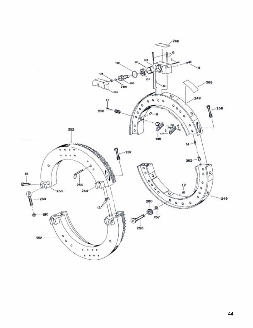
44.

SF SERIES LOW CLEARANCE SPLIT FRAME
60-000-42 LCSF 3642 60-000-48 LCSF 4248
45.
REF. NO. PART NO. QTY. DESCRIPTION
249 60-249-42 1 Ring, Stationary352 60-352-42 1 Ring, Rotating256 60-256-00 32 Eccentric Shaft257 60-257-00 32 Spacer, Bearing258 60-258-00 8 Screw, Clamp pad259 60-259-00 2 Screw, Captivated260 60-260-00 32 Bearing, Guide Wheel262 60-262-00 2 Bushing drill263 60-263-00 2 Bolt, Swing264 60-264-00 4 Pin, Detent265 59-117-00 1 Label, Open Machine266 60-180-00 1 Decal, Slide Warning150 22-150-00 2 Nut, 1/2-13" flange108 60-108-10 8 Pad, Clamp207 60-207-00 2 Screw, Captivated102 60-102-01 1 Housing, Pinion Rear103 60-103-01 1 Gear, Pinion104 60-104-36 1 Housing, Pinion Front125 60-125-00 1 Bearing, Pinion Rear126 60-126-00 1 Bearing, Pinion Front127 60-408-49 Extension Leg set to
cover entire clampingrange
133 60-133-00 16 Nut, Push 5/16160 60-160-00 1 Ring, Retaining161 60-161-00 1 Ring, Retaining209 60-209-00 1 Seal, Pinion
FASTENERS:
7 90-050-20 4 SHCS, 1/4-20 x 2”6 90-060-20 2 SHCS 5/16-18 x 2”13 90-076-07 6 Dowel 3/18” x 3/4”9 90-056-06 8 Dowel 1/4” x 5/8”12 90-075-05 32 Nut, Nylock 3/8-1614 90-096-10 2 Dowel, 1/2 x 115 90-097-65 2 1/2 x 1 1/2 Shoulder11 90-064-03 8 SSS, 5/16-18 x 3/82 90-060-08 8 SHCS 5/16-18 X 7/818 90-060-07 2 SHCS 5/16-18 X 3/43 90-075-54 32 Washer, 3/8 AN
Not Shown
90-099-91 1 Eye Bolt 1/2-1360-324-00 1 Serial Tag
REF. NO. PART NO. QTY. DESCRIPTION
249 60-249-48 1 Ring, Stationary352 60-352-48 1 Ring, Rotating256 60-256-00 32 Eccentric Shaft257 60-257-00 32 Spacer, Bearing258 60-258-00 8 Screw, Clamp pad259 60-259-00 2 Screw, Captivated260 60-260-00 32 Bearing, Guide Wheel262 60-262-00 2 Bushing drill263 60-263-00 2 Bolt, Swing264 60-264-00 4 Pin, Detent265 59-117-00 1 Label, Open Machine266 60-180-00 1 Decal, Slide Warning150 22-150-00 2 Nut, 1/2-13" flange108 60-108-10 8 Pad, Clamp207 60-207-00 2 Screw, Captivated102 60-102-00 1 Housing, Pinion Rear103 60-103-01 1 Gear, Pinion104 60-104-36 1 Housing, Pinion Front125 60-125-00 1 Bearing, Pinion Rear126 60-126-00 1 Bearing, Pinion Front127 60-408-49 Extension Leg set to
cover entire clampingrange
133 60-133-00 16 Nut, Push 5/16160 60-160-00 1 Ring, Retaining161 60-161-00 1 Ring, Retaining209 60-209-00 1 Seal, Pinion
FASTENERS:
7 90-050-20 4 SHCS, 1/4-20 x 2”6 90-060-20 2 SHCS 5/16-18 x 2”13 90-076-07 6 Dowel 3/18” x 3/4”9 90-056-06 8 Dowel 1/4” x 5/8”12 90-075-05 32 Nut, Nylock 3/8-1614 90-096-10 2 Dowel, 1/2 x 115 90-097-65 2 1/2 x 1 1/2 Shoulder11 90-064-03 8 SSS, 5/16-18 x 3/82 90-060-08 8 SHCS 5/16-18 X 7/818 90-060-07 2 SHCS 5/16-18 X 3/43 90-075-54 32 Washer, 3/8 AN
Not Shown
90-099-91 1 Eye Bolt 1/2-1360-324-00 1 Serial Tag
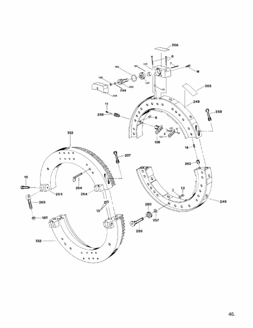
46.
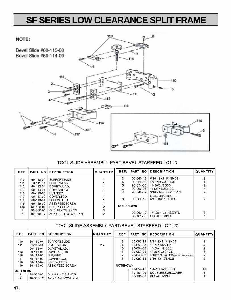
SF SERIES LOW CLEARANCE SPLIT FRAME
47.
REF. PART NO. DESCRIPTION QUANTITY
3 90-060-15 5’16-18X1-1/4 SHCS 34 90-050-08 1/4~20X7/8 SHCS 45 90-054-03 1I~20X1/2 SSS 26 90-060-05 11420X1/2 SHCS 47 90-046-02 3/16’X1/4~DOWEL PIN 2
(BEVEL SLIDE ONLY)8 90-060-15 5/1~1BX1/2" LHCS 2
NOT SHOWN
90-069-12 1/4-20 x 1/2 INSERTS 860-181-00 DECAL, TIMING 1
REF. PART NO. DESCRIPTION QUANTITY
110 60-110-01 SUPPORT,SUDE 1111 60-111-01 PLATE,WEAR 1112 60-112-01 DOVETAIL ADJ 1113 60-113-04 DOVETAILFIX 1116 60-116-00 NUT,FEED 1117 60-117-00 COVER,TOO 1118 60-118-04 SCREW,FEED 1119 60-119-00 ASSY,FEEDSCREW 1133 60-133-00 NUT, PUSH 5/16 2
1 90-060-00 5/16-18 x 7/8 SHCS 32 90-046-12 3/16 x 1-1/4 DOWEL PIN 2
TOOL SLIDE ASSEMBLY PART/BEVEL STARFEED LC 4-20
REF. PART NO. DESCRIPTION QUANTITY
3 90-060-15 5/1818X1-1/4SHCS 34 90-050-08 1/~20X7/8SHCS 45 90-064-00 1/~20x 1/2 SSS 26 90-050-05 1/~20X1/2 SHCS 67 90-046-02 3/16X1/4DWLPIN(BEVEL SLIDE ONLY) 28 90-060-15 5/1618x1/2’LHCS 2
NOTSHOWN90-059-12 1/4-20X1/2INSERT 1060-184-00 DOUBLEIBEVELCOVER 160-181-00 DECAL TIMING 1
REF. PART NO. DESCRIPTION QUANTITY
110 60-110-04 SUPPORT,SLIDE111 60-111-04 PLATE,WEAR 112
60-112-04 DOVETAIL ADJ.113 60-113-04 DOVETAIL, FIX116 60-118-00 NUT,FEED117 60-117-00 COVER,TOOL118 60-118-04 SCREW, FEED119 60-119-00 ASSY, FEED SCREW
FASTENERS1 90-060-00 5/16-18 x 7/8 SHCS2 90-056-12 1/4 x 1-1/4 DOWL PIN
TOOL SLIDE ASSEMBLY PART/BEVEL STARFEED LC1 -3
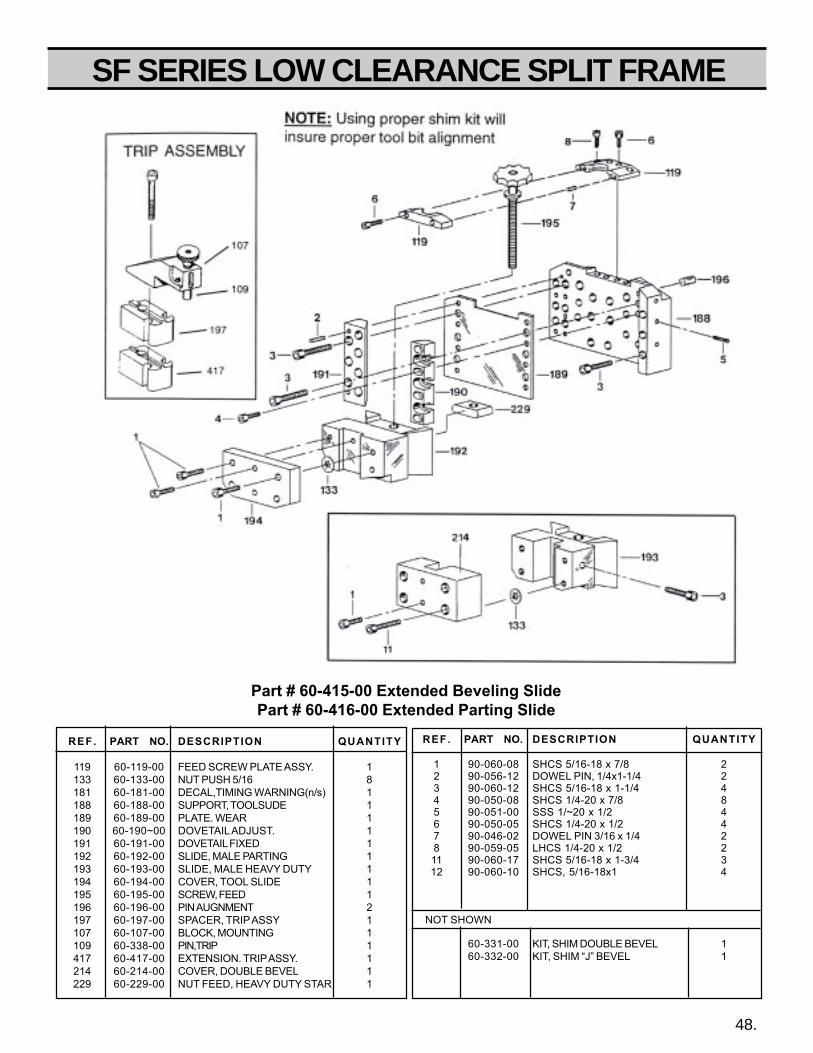
SF SERIES LOW CLEARANCE SPLIT FRAME
48.
REF. PART NO. DESCRIPTION QUANTITY
1 90-060-08 SHCS 5/16-18 x 7/8 22 90-056-12 DOWEL PIN, 1/4x1-1/4 23 90-060-12 SHCS 5/16-18 x 1-1/4 44 90-050-08 SHCS 1/4-20 x 7/8 85 90-051-00 SSS 1/~20 x 1/2 46 90-050-05 SHCS 1/4-20 x 1/2 47 90-046-02 DOWEL PIN 3/16 x 1/4 28 90-059-05 LHCS 1/4-20 x 1/2 211 90-060-17 SHCS 5/16-18 x 1-3/4 312 90-060-10 SHCS, 5/16-18x1 4
NOT SHOWN
60-331-00 KIT, SHIM DOUBLE BEVEL 160-332-00 KIT, SHIM “J” BEVEL 1
REF. PART NO. DESCRIPTION QUANTITY
119 60-119-00 FEED SCREW PLATE ASSY. 1133 60-133-00 NUT PUSH 5/16 8181 60-181-00 DECAL,TIMING WARNING(n/s) 1188 60-188-00 SUPPORT, TOOLSUDE 1189 60-189-00 PLATE. WEAR 1190 60-190~00 DOVETAIL ADJUST. 1191 60-191-00 DOVETAIL FIXED 1192 60-192-00 SLIDE, MALE PARTING 1193 60-193-00 SLIDE, MALE HEAVY DUTY 1194 60-194-00 COVER, TOOL SLIDE 1195 60-195-00 SCREW, FEED 1196 60-196-00 PIN AUGNMENT 2197 60-197-00 SPACER, TRIP ASSY 1107 60-107-00 BLOCK, MOUNTING 1109 60-338-00 PIN,TRIP 1417 60-417-00 EXTENSION. TRIP ASSY. 1214 60-214-00 COVER, DOUBLE BEVEL 1229 60-229-00 NUT FEED, HEAVY DUTY STAR 1
Part # 60-415-00 Extended Beveling SlidePart # 60-416-00 Extended Parting Slide

SF SERIES LOW CLEARANCE SPLIT FRAME
REF. NO. PART NO. QTY. DESCRIPTION
60-440-00 Extended Slide Group60-437-00 1 Slide Parting ( Ass'y )60-438-00 1 Slide Beveling ( Ass'y )660-439-00 2 Extended Trip Blocks
Slide Assembly314 60-314-00 1 Slide, Parting315 60-315-00 1 Slide, Beveling316 60-316-00 2 Dovetail318 60-318-00 1 Feed Screw Block319 60-319-00 1 Feed Screw320 60-320-00 1 Star Wheel321 60-321-00 2 Bushing322 60-322-00 14 Shim323 43-043-00 4 Thrust Washer324 43-064-00 2 Bearing192 60-192-00 1 Slide, Male Parting193 60-193-00 1 Slide, Male Beveling194 60-194-00 1 Cover, Tool196 60-196-00 2 Alignment Pin229 60-229-00 1 Nut, Feed133 60-133-00 4 Nut, Push
FASTENERS:01 90-065-05 1 5/16" Nut, Slotted02 90-019-43 1 Key, 3/32 x 3/8"03 90-016-55 1 3/32 x 1/2" Pin, Roll04 90-060-10 4 5/16-18 x 1" shcs05 90-060-08 6 5/16-18 x 7/8" shcs06 90-050-07 6 1/4-20 x 3/4" shcs07 90-060-12 1 5/16-18 x 1-1/4" shcs
Not Shown60-330-00 1 Shim Starwheel Nut60-331-00 1 Dbl. Bevel shim kit60-332-00 1 "J" Bevel shim kit
TRIP ASSEMBLY323 60-323-00 1 Block, Trip Extension269 60-269-00 1 Block, Extension046 43-046-00 4 Screw, Clamp266 60-266-00 1 Housing Trip067 43-067-00 2 Screw, Captive109 60-109-00 1 Pin, Trip
FASTENERS:08 90-026-55 1 1/8" x 1/2" Roll Pin09 90-059-08 1 Plunger, Spring10 90-900-52 1 1/4-20 Push Knob
Super Extended Starfeed Tool Slides
49.
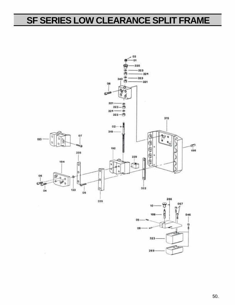
SF SERIES LOW CLEARANCE SPLIT FRAME
50.

SF SERIES LOW CLEARANCE SPLIT FRAME
REF. PART NO. DESCRIPTION QUANTITY
067 43-067-00 SCREW, CAPTIVATED 2071 60-230-00 SCREW, CAPTIVATED 4252 43-252-00 NUT, FEED 1137 53-137-00 BLOCK, TEMPLATE 2142 53-142-00 SLIDE, FEMALE 1143 53-143-00 GIB 1147 53-147-00 RAIL, SUPPORT 2152 53-152-00 SPRING 1153 53-153-00 ROLLER TRACK 2154 53-154-00 SHAFT 2155 53-155-00 PLATE, GIB 1215 53-215-00 SCREW, TOOL HOLDER ADJ. 1222 60-327-00 NUT FEED 1225 53-225-00 KNOB, ADJUST SCREW 1270 60-270-00 SCREW, FEED 1271 60-271-00 BLOCK, FEED 1272 60-272-20 BRIDGE 1273 60-273-01 SUPPORT, TOP 1274 60-274-00 SUPPORT, BOTTOM 1275 60-275-00 STARWHEEL 1276 60-276-00 GEAR, STARWHEEL 1277 60-277-00 GEAR, FEED SCREW 1278 60-278-00 MALE, SLIDE 1282 60-282-00 PLATE, SPRING 1283 60-283-00 PLATE, TOOL FEED 1284 60-284-00 SCREW, FEED 1285 60-285-00 BLOCK 1286 60-286-00 KNOB 1287 60-287-00 PLATE, COVER 1288 60-288-00 BEARING, SHOULDER 2289 60-289-00 BEARING, SHOULDER 2701 60-705-00 HOLDER, TOOL 1703 60-703-00 INSERT, BEVEL 1325 60-325-00 BUSHING 1326 60-326-00 BUSHING 1706 60-706-00 TOOL HOLDER, C’BORE 1
60-337-00 LABEL, SINGLE POINT (N/S) 1
FASTENERS
2 90-040-06 SHCS, 10-24x 5/8 23 90-040-07 SHCS, 10-24 X 3/4 54 90-045-07 NUT, 10-32 JAM 35 90-050-07 SHCS, 1/4-20 X 3/4 276 90-050-08 SHCS, 1/4-20 X 7/8 107 90-053-12 FHCS, 1/4-20 X 1-1/4 48 90-053-07 FHCS, 1/4-20 X 3/4 169 90-054-04 SSS, 1/4-20 X 3/8 7
10 90-036-57 Pin, Roll 5-32” x 3/4” 216 90-090-20 SHCS, 1/2-1 3x 3 418 90-095-10 Nut, Hex Slotted 1/2-20 220 90-040-57 SHCS, 10-32 x 3/4 221 90-026-58 PIN, ROLL 1/8 x 7/8 122 90-029-43 1/8 x 1/2 WOODRUFF 223 90-019-43 KEY, 3/32 x 5/8” 124 90-036-57 PIN ROLL, 5/32 x 3/4 226 90-054-10 SSS 1/4-20 x 1” 2
60-428-20 BRIDGE SLIDE (12”-20” RANGE) 60-428-28 BRIDGE SLIDE (22”-28” RANGE)
REF. PART NO. DESCRIPTION QUANTITY
067 43-067-00 SCREW, CAPTIVATED 2071 60-230-00 SCREW, CAPTIVATED 4252 43-252-00 NUT, FEED 1137 53-137-00 BLOCK, TEMPLATE 2142 53-142-00 SLIDE, FEMALE 1143 53-143-00 GIB 1147 53-147-00 RAIL, SUPPORT 2151 53-151-00 STUD 1152 53-152-00 SPRING 1153 53-153-00 ROLLER TRACK 2154 53-154-00 SHAFT 2155 53-155-00 PLATE, GIB 1215 53-215-00 SCREW, TOOL HOLDER ADJ. 1222 60-327-00 NUT FEED 1225 53-225-00 KNOB, ADJUST SCREW 1270 60-270-00 SCREW, FEED 1271 60-271-00 BLOCK, FEED 1272 60-272-28 BRIDGE 1273 60-273-00 SUPPORT, TOP 1274 60-274-00 SUPPORT, BOTTOM 1275 60-275-00 STARWHEEL 1276 60-276-00 GEAR, STARWHEEL 1277 60-277-00 GEAR, FEED SCREW 1278 60-278-00 MALE, SLIDE 1282 60-282-00 PLATE, SPRING 1283 60-283-00 PLATE, TOOL FEED 1284 60-284-00 SCREW, FEED 1285 60-285-00 BLOCK 1286 60-286-00 KNOB 1287 60-287-00 PLATE, COVER 1288 60-288-00 BEARING, SHOULDER 2289 60-289-00 BEARING, SHOULDER 2701 60-705-00 HOLDER, TOOL 1703 60-703-00 INSERT, BEVEL 1325 60-325-00 BUSHING 1326 60-326-00 BUSHING 1706 60-706-00 TOOL HOLDER, C’BORE 1
60-337-00 LABEL, SINGLE POINT (N/S) 1
FASTENERS
2 90-040-06 SHCS, 10-24 x 5/8 23 90-040-57 SHCS, 10-32 x 3/4 24 90-045-01 NUT, 10-32 JAM 25 90-050-07 SHCS, 1/4-20 X 3/4 206 90-050-08 SHCS, 1/4-20 X 7/8 107 90-050-12 SHCS, 1/4-20 X 1-1/4 48 90-053-07 FHCS, 1/4-20 X 3/4 209 90-054-04 SSS, 1/4-20 X 3/8 7
10 90-036-57 Pin, Roll 5-32” x 3/4” 212 90-070-04 SHCS, 3/8-16 x 1-1/2 416 90-090-20 SHCS, 1/2-13 x 2 417 90-095-09 NUT, JAM 1/2-13 218 90-075-07 NUT, SLOTTED 3/8 1
51.
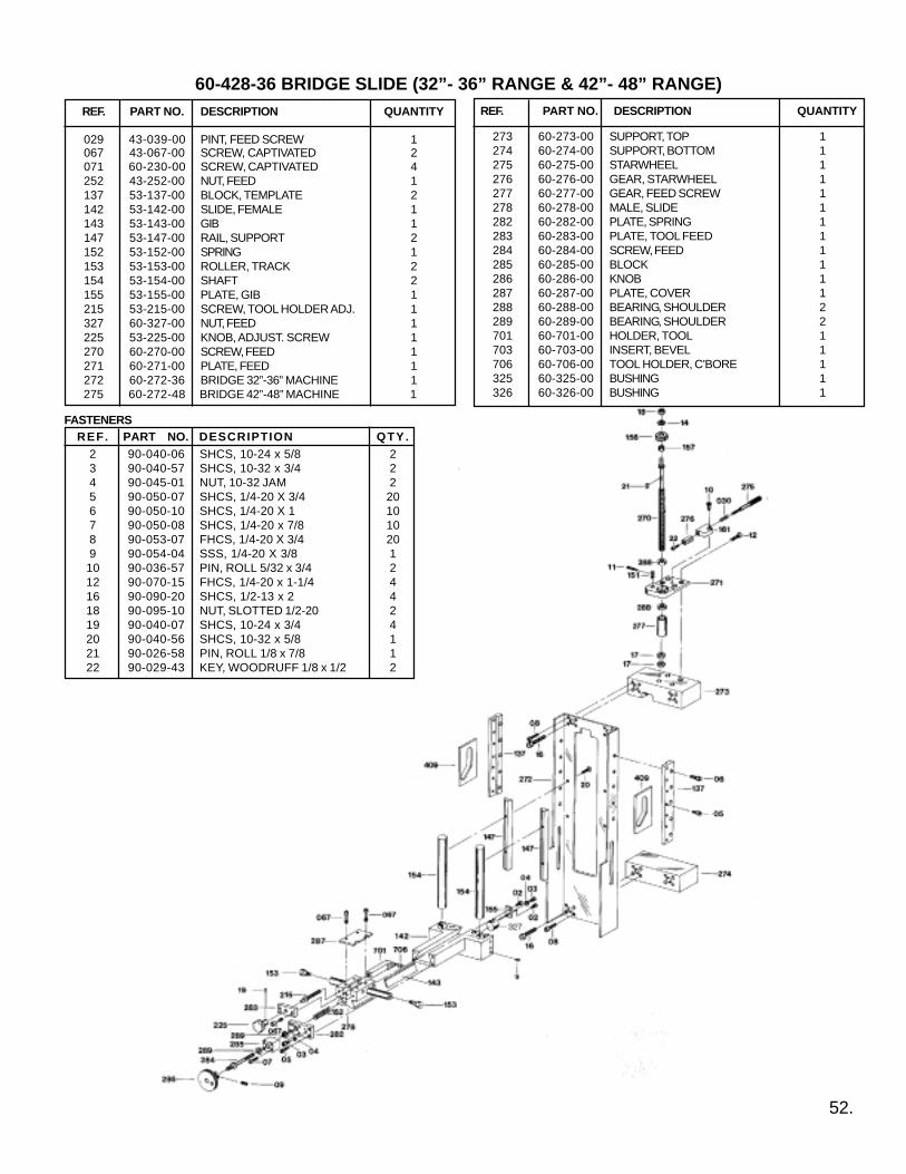
REF. PART NO. DESCRIPTION QUANTITY
029 43-039-00 PINT, FEED SCREW 1067 43-067-00 SCREW, CAPTIVATED 2071 60-230-00 SCREW, CAPTIVATED 4252 43-252-00 NUT, FEED 1137 53-137-00 BLOCK, TEMPLATE 2142 53-142-00 SLIDE, FEMALE 1143 53-143-00 GIB 1147 53-147-00 RAIL, SUPPORT 2152 53-152-00 SPRING 1153 53-153-00 ROLLER, TRACK 2154 53-154-00 SHAFT 2155 53-155-00 PLATE, GIB 1215 53-215-00 SCREW, TOOL HOLDER ADJ. 1327 60-327-00 NUT, FEED 1225 53-225-00 KNOB, ADJUST. SCREW 1270 60-270-00 SCREW, FEED 1271 60-271-00 PLATE, FEED 1272 60-272-36 BRIDGE 32”-36” MACHINE 1
60-428-36 BRIDGE SLIDE (32”- 36” RANGE & 42”- 48” RANGE)REF. PART NO. DESCRIPTION QUANTITY
REF. PART NO. DESCRIPTION QTY.2 90-040-06 SHCS, 10-24 x 5/8 23 90-040-57 SHCS, 10-32 x 3/4 24 90-045-01 NUT, 10-32 JAM 25 90-050-07 SHCS, 1/4-20 X 3/4 206 90-050-10 SHCS, 1/4-20 X 1 107 90-050-08 SHCS, 1/4-20 x 7/8 108 90-053-07 FHCS, 1/4-20 X 3/4 209 90-054-04 SSS, 1/4-20 X 3/8 110 90-036-57 PIN, ROLL 5/32 x 3/4 212 90-070-15 FHCS, 1/4-20 x 1-1/4 416 90-090-20 SHCS, 1/2-13 x 2 418 90-095-10 NUT, SLOTTED 1/2-20 219 90-040-07 SHCS, 10-24 x 3/4 420 90-040-56 SHCS, 10-32 x 5/8 121 90-026-58 PIN, ROLL 1/8 x 7/8 122 90-029-43 KEY, WOODRUFF 1/8 x 1/2 2
FASTENERS
273 60-273-00 SUPPORT, TOP 1274 60-274-00 SUPPORT, BOTTOM 1275 60-275-00 STARWHEEL 1276 60-276-00 GEAR, STARWHEEL 1277 60-277-00 GEAR, FEED SCREW 1278 60-278-00 MALE, SLIDE 1282 60-282-00 PLATE, SPRING 1283 60-283-00 PLATE, TOOL FEED 1284 60-284-00 SCREW, FEED 1285 60-285-00 BLOCK 1286 60-286-00 KNOB 1287 60-287-00 PLATE, COVER 1288 60-288-00 BEARING, SHOULDER 2289 60-289-00 BEARING, SHOULDER 2701 60-701-00 HOLDER, TOOL 1703 60-703-00 INSERT, BEVEL 1706 60-706-00 TOOL HOLDER, C’BORE 1325 60-325-00 BUSHING 1326 60-326-00 BUSHING 1
52.
275 60-272-48 BRIDGE 42”-48” MACHINE 1

SF SERIES LOW CLEARANCE SPLIT FRAME60-428-20 BRIDGE (01-103 RANGE) 60-405-UL COUNTERBORE SLIDE (204-1420 RANGE)
REF. PART NO. DESCRIPTION QUANTITY
038 43-038-00 LINER122 60-122-00 SCREW, CAPTIVE 6134 60-134-01 BAR, BORING 1135 60-135-00 INDICATOR 1136 60-136-01 BLOCK, PIVOT 1137 60-137-01 BLOCK, LOCKING 1138 60-136-01 PIVOT BLOCK 1139 60-139-01 BLOCK, SLIDE 1140 60-140-01 KEY 1141 60-141-01 BLOCK, FEED 1142 60-142-01 COVER, SCREW 1143 60-143-01 SCREW P05. LC 0-1 1143 60-143-02 SCREW P06. LC 1-2 1144 60-144-01 GUIDE ROD LC 0-1 1144 60-144-02 GUIDEROD L C1-2 1144 60-144-03 GUIDE ROD LC 2-3 1145 60-145-00 INSERT. SCREW 1146 60-146-00 DECAL, FEED 1147 60-147-00 SCREW, FEED 1148 60-148-00 BLOCK, SUPPORT 1149 60-149-00 PLATE. THRUST 1150 60-150-00 BUSHING 1151 60-151-00 SPRING, FEED 1152 60-152-00 HANDLE 1153 60-153-00 HANDLE 1154 60-154-00 BUSHING 1155 60-155-00 BUSHING 1156 60-156-01 BUSHING 1157 60-157-00 BUSHING 1177 60-177-01 DECAL, SCREW POS. 1700 60-700-01 C’BORE TOOL 1
fasteners1 90-050-30 1/4-20X3 SCHS 42 90-054-02 1/4-20 X 114 SSS 13 90-036-52 5/32X 1/4 ROLL PIN 24 90-056-05 1/4 X1/2 DOWEL PIN 65 90-040-55 10-32 X 1/2 SHCS 47 90-060-05 5/16-18 X 112 SHCS 38 90-001-03 6-32 X 3/8 SHCS 49 90-043-07 10-24X3/16 SSS 1
NOTSHOWN
43-053-00 STORAGE CASE 143-054-00 INSERT, FOAM 190-059-12 1/4-20 X 1/2 INSERT 490-069-12 5/16-18 X 1/2 INSERT 990-219-75 3/4-loX 3/4 INSERT 3
180 60-180-00 DECAL, SLIDE WARNING 1181 60-181-00 DECAL, GEAR WARNING 1
60-209-00 SEAL, PINION HOUSING 1
REF. PART NO. DESCRIPTION QUANTITY
038 43-038-00 LINER 2133 60-133-00 NUT, PUSH 5134 60-134-04 BAR, BORING 1135 60-135-00 INDICATOR 1136 80-136-04 BLOCK, PIVOT 1137 60-137-04 BLOCK, LOCKING 1138 60-138-04 PIVOT BLOCK 1139 60-139-04 BLOCK, SLIDE 1140 60-140-04 KEY 1141 60-141-04 BLOCK, FEED 1142 60-142-04 COVER, SCREW 1143 60-143-04 SCREW P05. LC 204 1143 60-143-06 SCREW P06 LC 206 1143 60-143-08 SCREW P05. LC 408 1143 60-143-10 SCREW P06. LC61O 1143 60-143-12 SCREW P08. LC 1420 1143 60-143-14 SCREW POS. LC 814 1143 60-143-16 SCREW P05. LC 1016 1144 60-144-08 GUIDE ROD LC 4-8 1144 60-144-10 GUIDE ROD LC 8-10 1144 60-144-12 GUIDE ROD LC 10-12 1144 60-144-14 GUIDE ROD LO 14-16 1145 60-145-00 INSERT, SCREW 1146 60-146-00 DECAL, FEED 1147 60-147-00 SCREW, FEED 1148 60-148-00 BLOCK, SUPPORT 1149 60-149-00 PLATE, THRUST 1150 60-150-00 BUSHING 1151 60-151-00 SPRING, FEED 1152 60-152-00 HANDLE 1154 60-154-00 BUSHING 1155 60-155-00 BUSHING 1156 60-156-01 BUSHING 1157 60-157-00 BUSHING 1158 60-158-00 COVER, SEAL 2159 60-159-00 SEAL, FELT 2177 60-177-04 DECAL, SCREW P05. 1700 60-700-04 C’BORE TOOL 1
fasteners1 90-050-30 1/4-20X3 SCHS 42 90-054-02 1/4-20X1/4 SSS 23 90-036-52 5/32 X 1/4 ROLL PIN 24 90-060-07 5/16-18 X 3/4 SHCS 25 90-040-03 10-24 X 318 SHCS 66 90040-05 10-24X 1/2 SHCS 37 90-074-05 3/8-16 X 1/2 SSS 28 90-060-05 5116-18 X 1/2 SHCS 29 90-060-15 5/16-18 X 1-1/2 SHCS 510 90-076-12 3/8 x 1-1/4 DOWEL 211 90-056-05 1/4 X 1/2 DOWEL 612 90-050-07 1/4-20 X 3/4 SHCS 4
NOTSHOWN
43-053-00 STORAGE CASE 143-054-00 INSERT, FOAM 190-059-12 1/4-20 X 1/2 INSERT 490-069-12 5/16-18 X 1/2 INSERT 990-219-75 3/4-loX 3/4 INSERT 3
180 60-180-00 DECAL, SLIDE WARNING 1181 60-181-00 DECAL, GEAR WARNING 1
60-209-00 SEAL, PINION HOUSING 1
53.
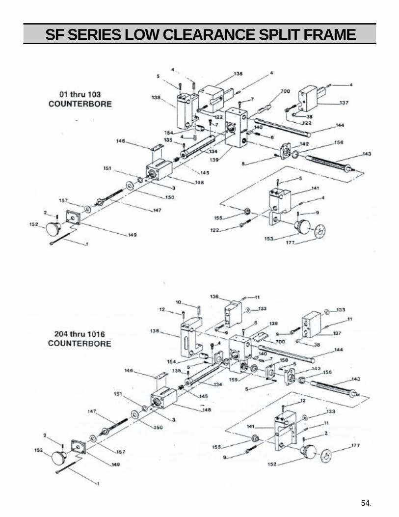
SF SERIES LOW CLEARANCE SPLIT FRAME
54.

SF SERIES LOW CLEARANCE SPLIT FRAME
REF PART # QTY DESCRIPTION REF PART # QTY. DESCRIPTION
27-188-00 1 Dial 27-192-00 1 sleeve27-189-00 1 Attachment, 27-197-00 1 Attachment,
indicator Universal27-190-00 1 Rod 60-187-00 1 Rod Indicator27-191-00 1 Sleeve 90-065-04 3 5/16-18 Jam Nut
60-414-00 DIAL INDICATOR SYSTEM
55.
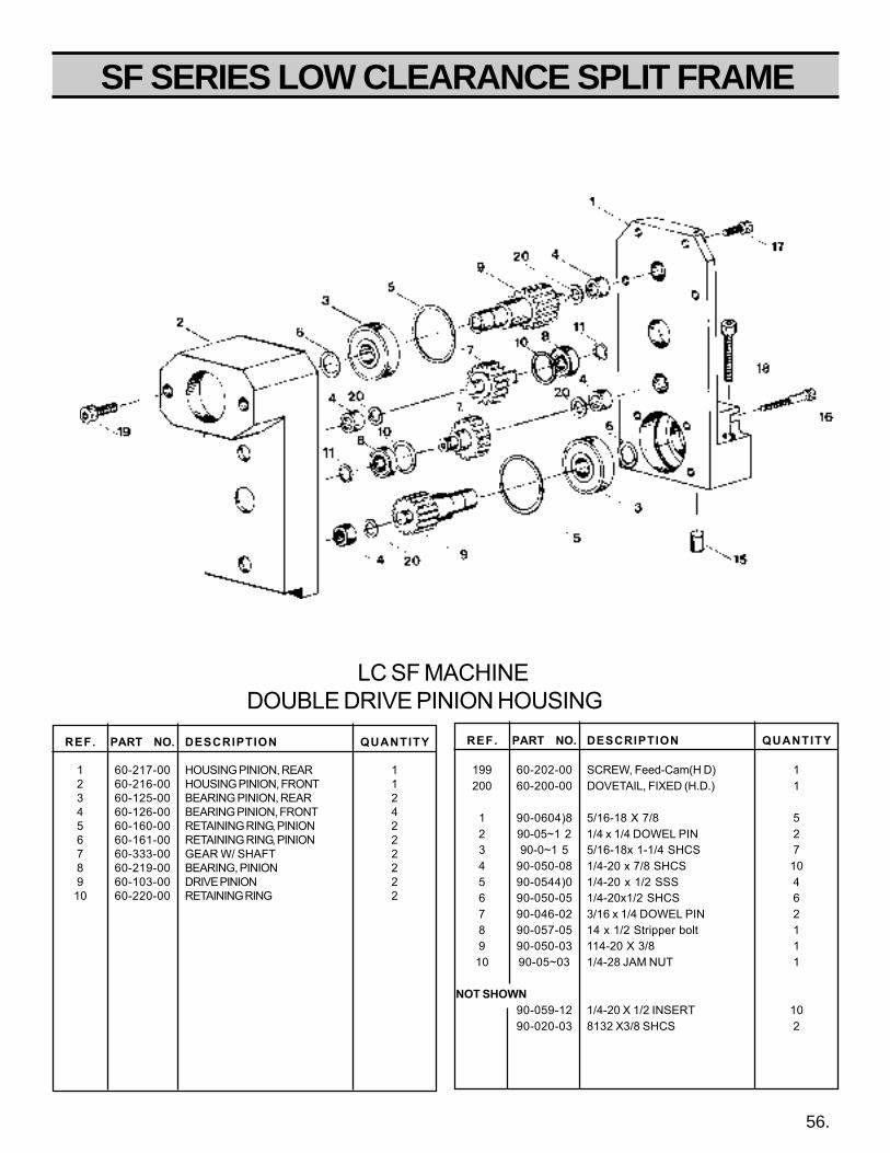
SF SERIES LOW CLEARANCE SPLIT FRAME
LC SF MACHINEDOUBLE DRIVE PINION HOUSING
REF. PART NO. DESCRIPTION QUANTITY
1 60-217-00 HOUSING PINION, REAR 12 60-216-00 HOUSING PINION, FRONT 13 60-125-00 BEARING PINION, REAR 24 60-126-00 BEARING PINION, FRONT 45 60-160-00 RETAINING RING, PINION 26 60-161-00 RETAINING RING, PINION 27 60-333-00 GEAR W/ SHAFT 28 60-219-00 BEARING, PINION 29 60-103-00 DRIVE PINION 210 60-220-00 RETAINING RING 2
REF. PART NO. DESCRIPTION QUANTITY
199 60-202-00 SCREW, Feed-Cam(H D) 1200 60-200-00 DOVETAIL, FIXED (H.D.) 1
1 90-0604)8 5/16-18 X 7/8 52 90-05~1 2 1/4 x 1/4 DOWEL PIN 23 90-0~1 5 5/16-18x 1-1/4 SHCS 74 90-050-08 1/4-20 x 7/8 SHCS 105 90-0544)0 1/4-20 x 1/2 SSS 46 90-050-05 1/4-20x1/2 SHCS 67 90-046-02 3/16 x 1/4 DOWEL PIN 28 90-057-05 14 x 1/2 Stripper bolt 19 90-050-03 114-20 X 3/8 110 90-05~03 1/4-28 JAM NUT 1
NOT SHOWN90-059-12 1/4-20 X 1/2 INSERT 1090-020-03 8132 X3/8 SHCS 2
56.
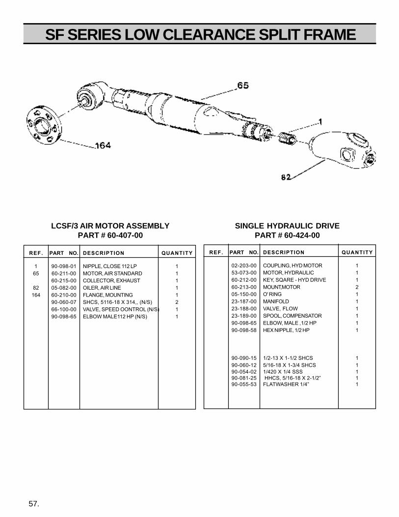
SF SERIES LOW CLEARANCE SPLIT FRAME
57.
REF. PART NO. DESCRIPTION QUANTITY
1 90-098-01 NIPPLE, CLOSE 112 LP 165 60-211-00 MOTOR, AIR STANDARD 1
60-215-00 COLLECTOR, EXHAUST 182 05-082-00 OILER, AIR LINE 1
164 60-210-00 FLANGE, MOUNTING 190-060-07 SHCS, 5116-18 X 314,, (N/S) 266-100-00 VALVE, SPEED OONTROL (N/S) 190-098-65 ELBOW MALE112 HP (N/S) 1
REF. PART NO. DESCRIPTION QUANTITY
02-203-00 COUPLING, HYD MOTOR 153-073-00 MOTOR, HYDRAULIC 160-212-00 KEY, SQARE - HYD DRIVE 160-213-00 MOUNT,MOTOR 205-150-00 O' RING 123-187-00 MANIFOLD 123-188-00 VALVE, FLOW 123-189-00 SPOOL, COMPENSATOR 190-098-65 ELBOW, MALE ,1/2 HP 190-098-58 HEX NIPPLE, 1/2 HP 1
90-090-15 1/2-13 X 1-1/2 SHCS 190-060-12 5/16-18 X 1-3/4 SHCS 190-054-02 1/420 X 1/4 SSS 190-081-25 HHCS, 5/16-18 X 2-1/2” 190-055-53 FLATWASHER 1/4” 1
LCSF/3 AIR MOTOR ASSEMBLYPART # 60-407-00
SINGLE HYDRAULIC DRIVEPART # 60-424-00

SF SERIES LOW CLEARANCE SPLIT FRAME
AIR MOTORSCHEMATICS

SF SERIES LOW CLEARANCE SPLIT FRAME
PART NO. DESCRIPTION QUANTITY
203101-1 CYLINDER (INCL. 863887-6) 1203102-9 ROTOR (NON REV.) 1869569 ROTOR BLADE 5
619377-5 FRONT ROTOR BEARING 1843444-1 REAR ROTOR BEARING 1863887-6 CYLINDER PIN 1865352-9 ROTOR LOCK NUT 1867528-2 MAKE UP RING 1867536-5 FRONT BEARING PLATE 1869572-8 REAR BEARING PLATE 1
MOTOR UNIT-STALL TYPE NON-REVERSIBLE
QUANTITYPART # NAME OF PART203062-5 2nd Red. Gear Bearing203105-2 2nd Red. Spider203107-8 2nd Red. Gear-15T (incl. 203062-5)832125-9 1st Red. Gear Pin844774-0 1st Red. Gear Bearing
2nd Red. Gear Bearing861485-1 1st Red. Spider-19T (incl. pin)864671-3 2nd Rod Gear Pin867526-6 1st Red. Gear-21T (incl. 844774-0)867544-9 Gear Case 50T
SPIDER
model part #
-3 861485-1
SPIDER
model part #
-3 861485-1
IDLER GEAR
model part #
-3 867526-6844774-0
832125-9
864671-3model part #
3 ,4,6 203062-5
IDLER GEAR
model part #
-3 203107-8
867544-9
MOTOR UNIT FOR NON-REVERSIBLE STALLTYPE TOOL WITH 7-TOOTH ROTOR
203101-1
203102-9
869569
619377-5
843444-1
863887-6
865352-9
867528-2
867536-5
869572-8
59.
6133
31331
Wachs 60-423-00 (55 Cleco NL 3T)
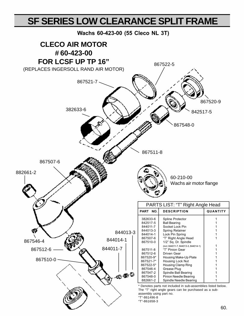
SF SERIES LOW CLEARANCE SPLIT FRAME
PART NO. DESCRIPTION QUANTITY
382633-6 Spline Protector 1842517-5 Ball Bearing 1844011-7 Socket Lock Pin 1844013-3 Spring Retainer 1844014-1 Lock Pin Spring 1867507-6 “T” Right Angle Head 1867510-0 1/2” Sq. Dr. Spindle
(incl. 844011-7, 844013-3, 844014-1) 1867511-8 “T” Pinion Gear 1867512-6 Driven Gear 1867520-9* Housing Make-Up Plate 1867521-7* Housing Lock Nut 1867522-5* Housing Clamp Ring 1867546-4 Grease Plug 1867547-2 Spindle Ball Bearing 1867548-0 Pinion Needle Bearing 1882661-2 Spindle Needle Bearing 1
PARTS LIST: “T” Right Angle Head
* Denotes parts not included in sub-assemblies listed below.The “T” right angle gears can be purchased as a sub-assembly using part no.“T”-861496-8“T”-861658-3
CLECO AIR MOTOR# 60-423-00
FOR LCSF UP TP 16”(REPLACES INGERSOLL RAND AIR MOTOR)
882661-2
867507-6
867522-5
867521-7
382633-6
867520-9
842517-5
867548-0
867511-8
844011-7
844014-1
844013-3
867510-0
867512-6
867546-4
60.
Wachs 60-423-00 (55 Cleco NL 3T)
60-210-00Wachs air motor flange
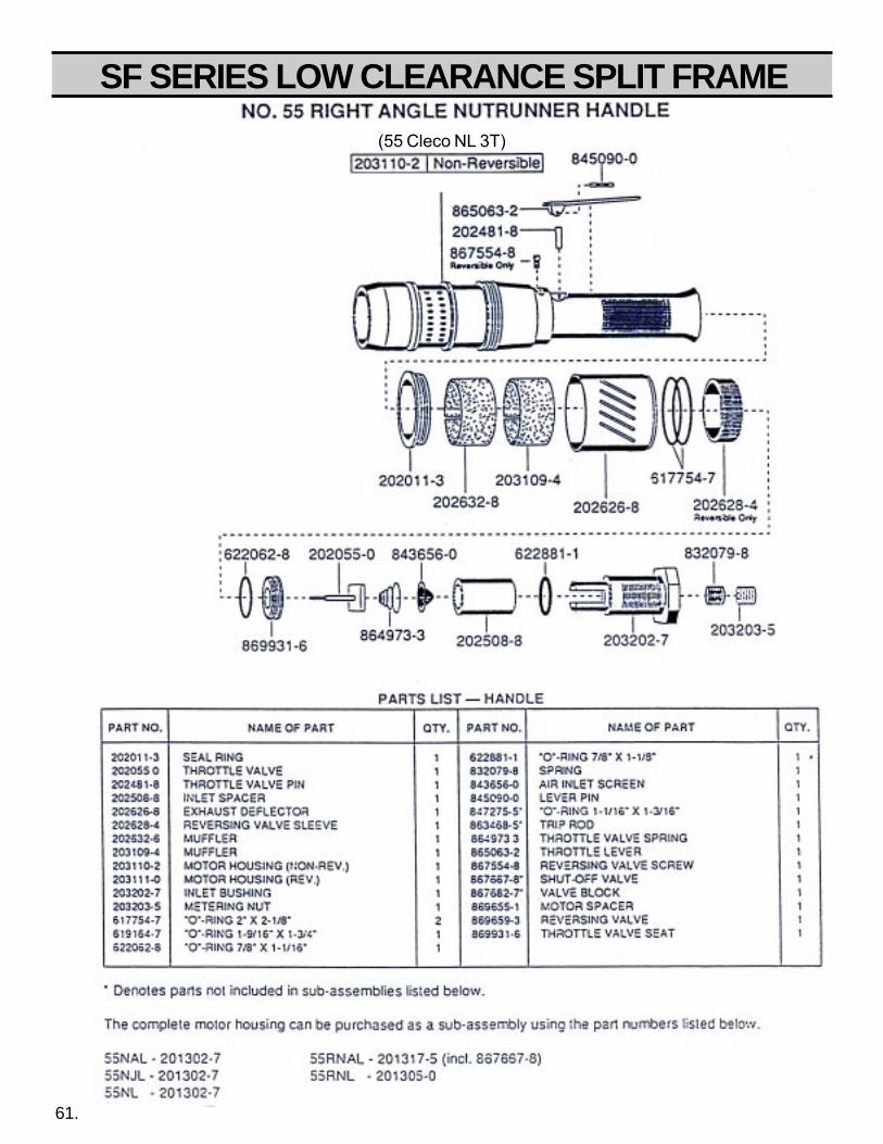
SF SERIES LOW CLEARANCE SPLIT FRAME
61.
(55 Cleco NL 3T)
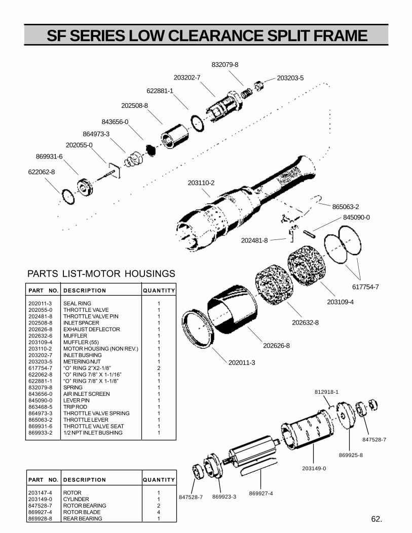
SF SERIES LOW CLEARANCE SPLIT FRAME
PART NO. DESCRIPTION QUANTITY
202011-3 SEAL RING 1202055-0 THROTTLE VALVE 1202481-8 THROTTLE VALVE PIN 1202508-8 INLET SPACER 1202626-8 EXHAUST DEFLECTOR 1202632-6 MUFFLER 1203109-4 MUFFLER (55) 1203110-2 MOTOR HOUSING (NON REV.) 1203202-7 INLET BUSHING 1203203-5 METERING NUT 1617754-7 “O” RING 2”X2-1/8” 2622062-8 “O” RING 7/8” X 1-1/16” 1622881-1 “O” RING 7/8” X 1-1/8” 1832079-8 SPRING 1843656-0 AIR INLET SCREEN 1845090-0 LEVER PIN 1863468-5 TRIP ROD 1864973-3 THROTTLE VALVE SPRING 1865063-2 THROTTLE LEVER 1869931-6 THROTTLE VALVE SEAT 1869933-2 1/2 NPT INLET BUSHING 1
203202-7
622881-1
202508-8
843656-0
864973-3
202055-0
869931-6
832079-8
203203-5
622062-8
203110-2
865063-2
617754-7
845090-0
202481-8
203109-4
202632-8
202626-8
202011-3
PARTS LIST-MOTOR HOUSINGS
62.
847528-7
847528-7
203149-0
869925-8
869927-4869923-3
812918-1
PART NO. DESCRIPTION QUANTITY
203147-4 ROTOR 1203149-0 CYLINDER 1847528-7 ROTOR BEARING 2869927-4 ROTOR BLADE 4869928-8 REAR BEARING 1
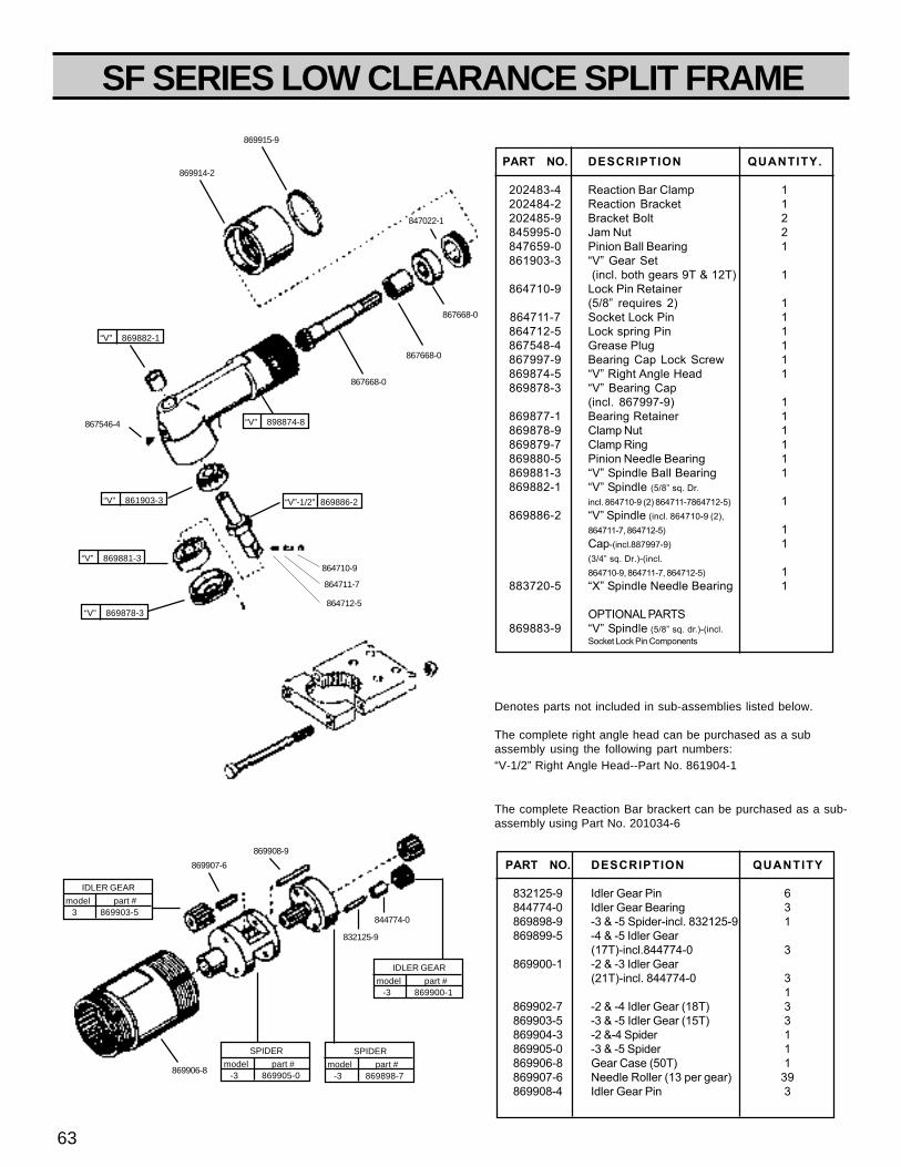
SF SERIES LOW CLEARANCE SPLIT FRAME
PART NO. DESCRIPTION QUANTITY
832125-9 Idler Gear Pin 6844774-0 Idler Gear Bearing 3869898-9 -3 & -5 Spider-incl. 832125-9 1869899-5 -4 & -5 Idler Gear
(17T)-incl.844774-0 3869900-1 -2 & -3 Idler Gear
(21T)-incl. 844774-0 31
869902-7 -2 & -4 Idler Gear (18T) 3869903-5 -3 & -5 Idler Gear (15T) 3869904-3 -2 &-4 Spider 1869905-0 -3 & -5 Spider 1869906-8 Gear Case (50T) 1869907-6 Needle Roller (13 per gear) 39869908-4 Idler Gear Pin 3
PART NO. DESCRIPTION QUANTITY.
202483-4 Reaction Bar Clamp 1202484-2 Reaction Bracket 1202485-9 Bracket Bolt 2845995-0 Jam Nut 2847659-0 Pinion Ball Bearing 1861903-3 “V” Gear Set
(incl. both gears 9T & 12T) 1864710-9 Lock Pin Retainer
(5/8” requires 2) 1864711-7 Socket Lock Pin 1864712-5 Lock spring Pin 1867548-4 Grease Plug 1867997-9 Bearing Cap Lock Screw 1869874-5 “V” Right Angle Head 1869878-3 “V” Bearing Cap
(incl. 867997-9) 1869877-1 Bearing Retainer 1869878-9 Clamp Nut 1869879-7 Clamp Ring 1869880-5 Pinion Needle Bearing 1869881-3 “V” Spindle Ball Bearing 1869882-1 “V” Spindle (5/8” sq. Dr.
incl. 864710-9 (2) 864711-7864712-5) 1869886-2 “V” Spindle (incl. 864710-9 (2),
864711-7, 864712-5) 1Cap-(incl.887997-9) 1(3/4” sq. Dr.)-(incl.864710-9, 864711-7, 864712-5) 1
883720-5 “X” Spindle Needle Bearing 1
OPTIONAL PARTS869883-9 “V” Spindle (5/8” sq. dr.)-(incl.
Socket Lock Pin Components
Denotes parts not included in sub-assemblies listed below.
The complete right angle head can be purchased as a subassembly using the following part numbers:“V-1/2” Right Angle Head--Part No. 861904-1
The complete Reaction Bar brackert can be purchased as a sub-assembly using Part No. 201034-6
864710-9
867546-4
869914-2
869915-9
847022-1
864711-7
864712-5
867668-0
867668-0
867668-0
“V” 898874-8
“V” 861903-3 “V”-1/2” 869886-2
“V” 869878-3
IDLER GEAR
model part # -3 869900-1
844774-0
832125-9
869908-9
869907-6
SPIDER
model part # -3 869905-0
869906-8
SPIDER
model part # -3 869898-7
63
“V” 869882-1
“V” 869881-3
IDLER GEAR
model part # 3 869903-5
SF SERIES LOW CLEARANCE SPLIT FRAME
To place an order or to get more detailed information on any E.H. Wachs products, call us at:1-800-323-8185.
ORDERING REPLACEMENT PARTS
Please use parts list provided in manual. Have part description and part number of required replacementpart or parts to help expedite order and insure proper parts are being ordered.
REPAIR INFORMATION
Please call E.H. Wachs Company prior to returning any equipment for repair. We will advise you of shippingand handling. Please enclose with equipment to be repaired your name, address, phone number and a briefdescription of problem or work to be done or estimated.
All repair work done at our plant will be estimated and the customer advised of cost and time required tocomplete repair.
WARRANTY INFORMATION
Enclosed with the manual is a warranty card. Please fill out the registration card and return to E.H. Wachs.Retain the owners registration record and warranty card for your information.
RETURN GOODS ADDRESS
E.H. Wachs Company100 Shepard Street
Wheeling, Illinois 60090
Call or Write:
E.H. Wachs Company100 Shepard Street
Wheeling, Illinois 60090
847-537-8800
FAX: 847-520-1147 • 847-520-1168
Toll-Free: 1-800-323-8185
64.
SECTION X LCSF ORDERING INFORMATION
Enter Your Machines Serial Number Here ForProper Record Keeping and Ordering Reference.
TUBE & PIPECUT-OFF MACHINES
Mod. LCSF/3 Ser.No.
Related Documents