IEEE TRANSACTIONS ON IMAGE PROCESSING, VOL. 14, NO. 2, FEBRUARY 2005 253 Lossless Generalized-LSB Data Embedding Mehmet Utku Celik, Student Member, IEEE, Gaurav Sharma, Senior Member, IEEE, Ahmet Murat Tekalp, Fellow, IEEE, and Eli Saber, Senior Member, IEEE Abstract—We present a novel lossless (reversible) data-embed- ding technique, which enables the exact recovery of the original host signal upon extraction of the embedded information. A gener- alization of the well-known least significant bit (LSB) modification is proposed as the data-embedding method, which introduces ad- ditional operating points on the capacity-distortion curve. Lossless recovery of the original is achieved by compressing portions of the signal that are susceptible to embedding distortion and transmit- ting these compressed descriptions as a part of the embedded pay- load. A prediction-based conditional entropy coder which utilizes unaltered portions of the host signal as side-information improves the compression efficiency and, thus, the lossless data-embedding capacity. Index Terms—Arithmetic coding, conditional entropy coding, context modeling, data embedding, data hiding, least significant bit (LSB) modification, watermark. I. INTRODUCTION M ULTIMEDIA data embedding, or digital watermarking, 1 refers to the process of inserting information bits into a host multimedia signal without introducing perceptible artifacts [1]–[3]. A variety of embedding techniques, ranging from high- capacity bit modification to transform-domain spread spectrum methods, are used in various applications such as authentication [4], [5], meta-data tagging, content-protection, and secret com- munications. Most multimedia data-embedding techniques modify and, hence, distort the host signal in order to insert the additional information (other techniques may encode this information into the “representation” of the signal, e.g., color space). The distor- tion induced on the host signal by the data-embedding technique is called the embedding distortion. Often, the embedding dis- tortion is small, yet irreversible, i.e., it cannot be removed to Manuscript received July 17, 2002; revised March 17, 2004. The associate editor coordinating the review of this manuscript and approving it for publica- tion was Dr. Gopal Pingali. M. U. Celik is with the Electrical and Computer Engineering Depart- ment, University of Rochester, Rochester, NY 14627-0126 USA (e-mail: [email protected]). G. Sharma is with the Electrical and Computer Engineering Depart- ment and the Department of Biostatistics and Computational Biology, University of Rochester, Rochester, NY 14627-0126 USA (e-mail: [email protected]). A. M. Tekalp is with College of Engineering, Koc University, Is- tanbul, Turkey, and also with the Department of Electrical and Computer Engineering, University of Rochester, NY 14627-0126 USA (e-mail: [email protected]). E. Saber is with Xerox Corporation, Webster, NY 14580 USA, and also with the Department of Electrical and Computer Engineering, University of Rochester, NY 14627-0126 USA (e-mail: [email protected]). Digital Object Identifier 10.1109/TIP.2004.840686 1 Throughout this paper, the terms data embedding, digital watermarking, and watermarking are used interchangeably and subtle nuances among the terms are ignored. Fig. 1. Lossless data embedding, extraction, and recovery. recover the original host signal. In many applications, the loss of host signal fidelity is not prohibitive as long as original and modified signals are perceptually equivalent. However, in a number of domains—such as military, legal and medical imaging—although some embedding distortion is admissible, permanent loss of signal fidelity is undesirable. This highlights the need for lossless data embedding 2 techniques. These tech- niques, like their lossy counterparts, insert information bits by modifying the host signal, thus inducing an embedding distortion. Nevertheless, they also enable the removal of such distortions and the exact—lossless—restoration of the original host signal after extraction of embedded information. Particular applications include embedding of DICOM header [6] informa- tion into medical images and providing fragile authentication watermarking for aerial/surveillance images [7]. A general block diagram representing lossless data-embed- ding schemes is seen in Fig. 1. The lossless embedding step takes the host signal and the message data and produces a water- marked signal in which the message data is embedded. The data extraction and recovery process uses the watermarked signal to extract the embedded data and to recover the original host signal exactly. Note that though the recovery process allows re- construction of the original host signal with no distortion, it is still desirable to keep the embedding distortion, i.e., the differ- ence between the host and watermarked signal, to a minimum so that applications that do not have access to the extraction and recovery process do not incur a heavy penalty in image quality. Lossless data-embedding techniques may be classified into one of the following two categories: Type-I algorithms [8], [9] employ additive spread spectrum techniques, where a spread spectrum signal corresponding to the information payload is superimposed on the host in the embedding phase. At the decoder, detection of the embedded information is followed by a restoration step where the watermark signal is removed, 2 In the literature, lossless data embedding is also referred as reversible, in- vertible, or distortion-free data embedding. 1057-7149/$20.00 © 2005 IEEE

Welcome message from author
This document is posted to help you gain knowledge. Please leave a comment to let me know what you think about it! Share it to your friends and learn new things together.
Transcript
IEEE TRANSACTIONS ON IMAGE PROCESSING, VOL. 14, NO. 2, FEBRUARY 2005 253
Lossless Generalized-LSB Data EmbeddingMehmet Utku Celik, Student Member, IEEE, Gaurav Sharma, Senior Member, IEEE,
Ahmet Murat Tekalp, Fellow, IEEE, and Eli Saber, Senior Member, IEEE
Abstract—We present a novel lossless (reversible) data-embed-ding technique, which enables the exact recovery of the originalhost signal upon extraction of the embedded information. A gener-alization of the well-known least significant bit (LSB) modificationis proposed as the data-embedding method, which introduces ad-ditional operating points on the capacity-distortion curve. Losslessrecovery of the original is achieved by compressing portions of thesignal that are susceptible to embedding distortion and transmit-ting these compressed descriptions as a part of the embedded pay-load. A prediction-based conditional entropy coder which utilizesunaltered portions of the host signal as side-information improvesthe compression efficiency and, thus, the lossless data-embeddingcapacity.
Index Terms—Arithmetic coding, conditional entropy coding,context modeling, data embedding, data hiding, least significantbit (LSB) modification, watermark.
I. INTRODUCTION
MULTIMEDIA data embedding, or digital watermarking,1
refers to the process of inserting information bits into ahost multimedia signal without introducing perceptible artifacts[1]–[3]. A variety of embedding techniques, ranging from high-capacity bit modification to transform-domain spread spectrummethods, are used in various applications such as authentication[4], [5], meta-data tagging, content-protection, and secret com-munications.
Most multimedia data-embedding techniques modify and,hence, distort the host signal in order to insert the additionalinformation (other techniques may encode this information intothe “representation” of the signal, e.g., color space). The distor-tion induced on the host signal by the data-embedding techniqueis called the embedding distortion. Often, the embedding dis-tortion is small, yet irreversible, i.e., it cannot be removed to
Manuscript received July 17, 2002; revised March 17, 2004. The associateeditor coordinating the review of this manuscript and approving it for publica-tion was Dr. Gopal Pingali.
M. U. Celik is with the Electrical and Computer Engineering Depart-ment, University of Rochester, Rochester, NY 14627-0126 USA (e-mail:[email protected]).
G. Sharma is with the Electrical and Computer Engineering Depart-ment and the Department of Biostatistics and Computational Biology,University of Rochester, Rochester, NY 14627-0126 USA (e-mail:[email protected]).
A. M. Tekalp is with College of Engineering, Koc University, Is-tanbul, Turkey, and also with the Department of Electrical and ComputerEngineering, University of Rochester, NY 14627-0126 USA (e-mail:[email protected]).
E. Saber is with Xerox Corporation, Webster, NY 14580 USA, and alsowith the Department of Electrical and Computer Engineering, University ofRochester, NY 14627-0126 USA (e-mail: [email protected]).
Digital Object Identifier 10.1109/TIP.2004.840686
1Throughout this paper, the terms data embedding, digital watermarking, andwatermarking are used interchangeably and subtle nuances among the terms areignored.
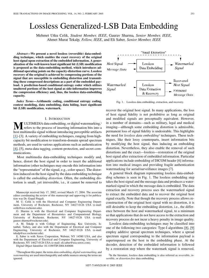
Fig. 1. Lossless data embedding, extraction, and recovery.
recover the original host signal. In many applications, the lossof host signal fidelity is not prohibitive as long as originaland modified signals are perceptually equivalent. However,in a number of domains—such as military, legal and medicalimaging—although some embedding distortion is admissible,permanent loss of signal fidelity is undesirable. This highlightsthe need for lossless data embedding2 techniques. These tech-niques, like their lossy counterparts, insert information bitsby modifying the host signal, thus inducing an embeddingdistortion. Nevertheless, they also enable the removal of suchdistortions and the exact—lossless—restoration of the originalhost signal after extraction of embedded information. Particularapplications include embedding of DICOM header [6] informa-tion into medical images and providing fragile authenticationwatermarking for aerial/surveillance images [7].
A general block diagram representing lossless data-embed-ding schemes is seen in Fig. 1. The lossless embedding steptakes the host signal and the message data and produces a water-marked signal in which the message data is embedded. The dataextraction and recovery process uses the watermarked signalto extract the embedded data and to recover the original hostsignal exactly. Note that though the recovery process allows re-construction of the original host signal with no distortion, it isstill desirable to keep the embedding distortion, i.e., the differ-ence between the host and watermarked signal, to a minimumso that applications that do not have access to the extraction andrecovery process do not incur a heavy penalty in image quality.
Lossless data-embedding techniques may be classified intoone of the following two categories: Type-I algorithms [8], [9]employ additive spread spectrum techniques, where a spreadspectrum signal corresponding to the information payload issuperimposed on the host in the embedding phase. At thedecoder, detection of the embedded information is followedby a restoration step where the watermark signal is removed,
2In the literature, lossless data embedding is also referred as reversible, in-vertible, or distortion-free data embedding.
1057-7149/$20.00 © 2005 IEEE
254 IEEE TRANSACTIONS ON IMAGE PROCESSING, VOL. 14, NO. 2, FEBRUARY 2005
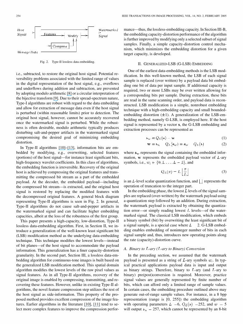
Fig. 2. Type-II lossless data embedding.
i.e., subtracted, to restore the original host signal. Potential re-versibility problems associated with the limited range of valuesin the digital representation of the host signal, e.g., overflowsand underflows during addition and subtraction, are preventedby adopting modulo arithmetic [8] or a circular interpretation ofthe bijective transform [9]. Due to their spread-spectrum nature,Type-I algorithms are robust with regard to the data embeddingand allow for extraction of message data even if the host signalis perturbed (within reasonable limits) prior to detection. Theoriginal host signal, however, cannot be accurately recoveredonce the watermarked signal is perturbed. While the robust-ness is often desirable, modulo arithmetic typically producesdisturbing salt-and-pepper artifacts in the watermarked signalcompromising the desired goal of minimizing embeddingdistortion.
In Type-II algorithms [10]–[13], information bits are em-bedded by modifying, e.g., overwriting, selected features(portions) of the host signal—for instance least significant bits,high-frequency wavelet coefficients. In this class of algorithms,the embedding function is irreversible. Recovery of the originalhost is achieved by compressing the original features and trans-mitting the compressed bit stream as a part of the embeddedpayload. At the decoder, the embedded payload—includingthe compressed bit stream—is extracted, and the original hostsignal is restored by replacing the modified features withthe decompressed original features. A general block diagramrepresenting Type-II algorithms is seen in Fig. 2. In general,Type-II algorithms do not cause salt-and-pepper artifacts inthe watermarked signal and can facilitate higher embeddingcapacities, albeit at the loss of the robustness of the first group.
This paper presents a high-capacity, low-distortion, Type-IIlossless data-embedding algorithm. First, in Section II, we in-troduce a generalization of the well-known least significant bit(LSB) modification method as the underlying data-embeddingtechnique. This technique modifies the lowest levels—insteadof bit planes—of the host signal to accommodate the payloadinformation. This generalization has a finer capacity-distortiongranularity. In the second part, Section III, a lossless data-em-bedding algorithm for continuous-tone images is built based onthe generalized LSB modification method. This spatial domainalgorithm modifies the lowest levels of the raw pixel values assignal features. As in all Type-II algorithms, recovery of theoriginal image is enabled by compressing, transmitting, and re-covering these features. However, unlike in existing Type-II al-gorithms, the novel feature compression step utilizes the rest ofthe host signal as side-information. This property of the pro-posed method provides excellent compression of the image fea-tures. Earlier algorithms in the literature [10], [11] tend to se-lect more complex features to improve the compression perfor-
mance—thus, the lossless-embedding capacity. In Section III-B,the embedding capacity-distortion performance of the algorithmis further improved by modifying only a selected subset of signalsamples. Finally, a simple capacity-distortion control mecha-nism, which minimizes the embedding distortion for a giventarget capacity, is developed.
II. GENERALIZED-LSB (G-LSB) EMBEDDING
One of the earliest data-embedding methods is the LSB mod-ification. In this well-known method, the LSB of each signalsample is replaced (over written) by a payload data bit embed-ding one bit of data per input sample. If additional capacity isrequired, two or more LSBs may be over written allowing fora corresponding bits per sample. During extraction, these bitsare read in the same scanning order, and payload data is recon-structed. LSB modification is a simple, nonrobust embeddingtechnique with a high-embedding capacity and small bounded-embedding distortion ( 1). A generalization of the LSB-em-bedding method, namely G-LSB, is employed here. If the hostsignal is represented by a vector , the G-LSB embedding andextraction processes can be represented as
(1)
(2)
where represents the signal containing the embedded infor-mation, represents the embedded payload vector of -arysymbols, i.e., , and
(3)
is an -level scalar quantization function, and represents theoperation of truncation to the integer part.
In the embedding phase, the lowest levels of the signal sam-ples are replaced (over-written) by the watermark payload usinga quantization step followed by an addition. During extraction,the watermark payload is extracted by obtaining the quantiza-tion error—or simply reading lowest levels—of the water-marked signal. The classical LSB modification, which embedsa binary symbol (bit) by overwriting the least significant bit ofa signal sample, is a special case where 2. G-LSB embed-ding enables embedding of noninteger number of bits in eachsignal sample and, thus, introduces new operating points alongthe rate (capacity)-distortion curve.
A. Binary to -ary ( -ary to Binary) Conversion
In the preceding section, we assumed that the watermarkpayload is presented as a string of -ary symbols . In typ-ical practical applications payload data is input and outputas binary strings. Therefore, binary to -ary (and -ary tobinary) pre(post)conversion is required. Moreover, practicesignal values are generally represented by finite number ofbits, which can afford only a limited range of sample values.In certain cases, the embedding procedure outlined above maygenerate out-of-range sample values. For instance, in a 8 bpprepresentation (range is [0, 255]) the embedding algorithmwith operating parameters 6, 252, and 5will output 257, which cannot be represented by an 8-bit
CELIK et al.: LOSSLESS GENERALIZED-LSB DATA EMBEDDING 255
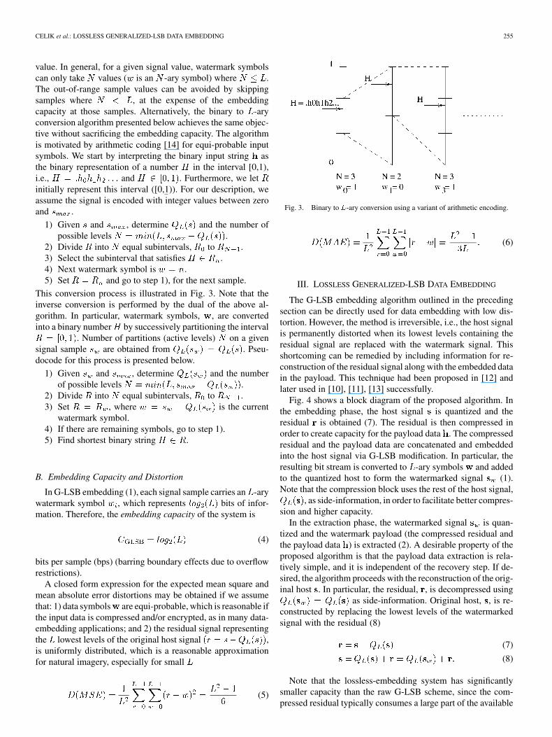
value. In general, for a given signal value, watermark symbolscan only take values ( is an -ary symbol) where .The out-of-range sample values can be avoided by skippingsamples where , at the expense of the embeddingcapacity at those samples. Alternatively, the binary to -aryconversion algorithm presented below achieves the same objec-tive without sacrificing the embedding capacity. The algorithmis motivated by arithmetic coding [14] for equi-probable inputsymbols. We start by interpreting the binary input string asthe binary representation of a number in the interval [0,1),i.e., and . Furthermore, we letinitially represent this interval ([0,1)). For our description, weassume the signal is encoded with integer values between zeroand .
1) Given and , determine and the number ofpossible levels .
2) Divide into equal subintervals, to .3) Select the subinterval that satisfies .4) Next watermark symbol is .5) Set and go to step 1), for the next sample.
This conversion process is illustrated in Fig. 3. Note that theinverse conversion is performed by the dual of the above al-gorithm. In particular, watermark symbols, , are convertedinto a binary number by successively partitioning the interval
. Number of partitions (active levels) on a givensignal sample are obtained from . Pseu-docode for this process is presented below.
1) Given and , determine and the numberof possible levels .
2) Divide into equal subintervals, to .3) Set , where is the current
watermark symbol.4) If there are remaining symbols, go to step 1).5) Find shortest binary string .
B. Embedding Capacity and Distortion
In G-LSB embedding (1), each signal sample carries an -arywatermark symbol , which represents bits of infor-mation. Therefore, the embedding capacity of the system is
(4)
bits per sample (bps) (barring boundary effects due to overflowrestrictions).
A closed form expression for the expected mean square andmean absolute error distortions may be obtained if we assumethat: 1) data symbols are equi-probable, which is reasonable ifthe input data is compressed and/or encrypted, as in many data-embedding applications; and 2) the residual signal representingthe lowest levels of the original host signal ,is uniformly distributed, which is a reasonable approximationfor natural imagery, especially for small
(5)
Fig. 3. Binary to L-ary conversion using a variant of arithmetic encoding.
(6)
III. LOSSLESS GENERALIZED-LSB DATA EMBEDDING
The G-LSB embedding algorithm outlined in the precedingsection can be directly used for data embedding with low dis-tortion. However, the method is irreversible, i.e., the host signalis permanently distorted when its lowest levels containing theresidual signal are replaced with the watermark signal. Thisshortcoming can be remedied by including information for re-construction of the residual signal along with the embedded datain the payload. This technique had been proposed in [12] andlater used in [10], [11], [13] successfully.
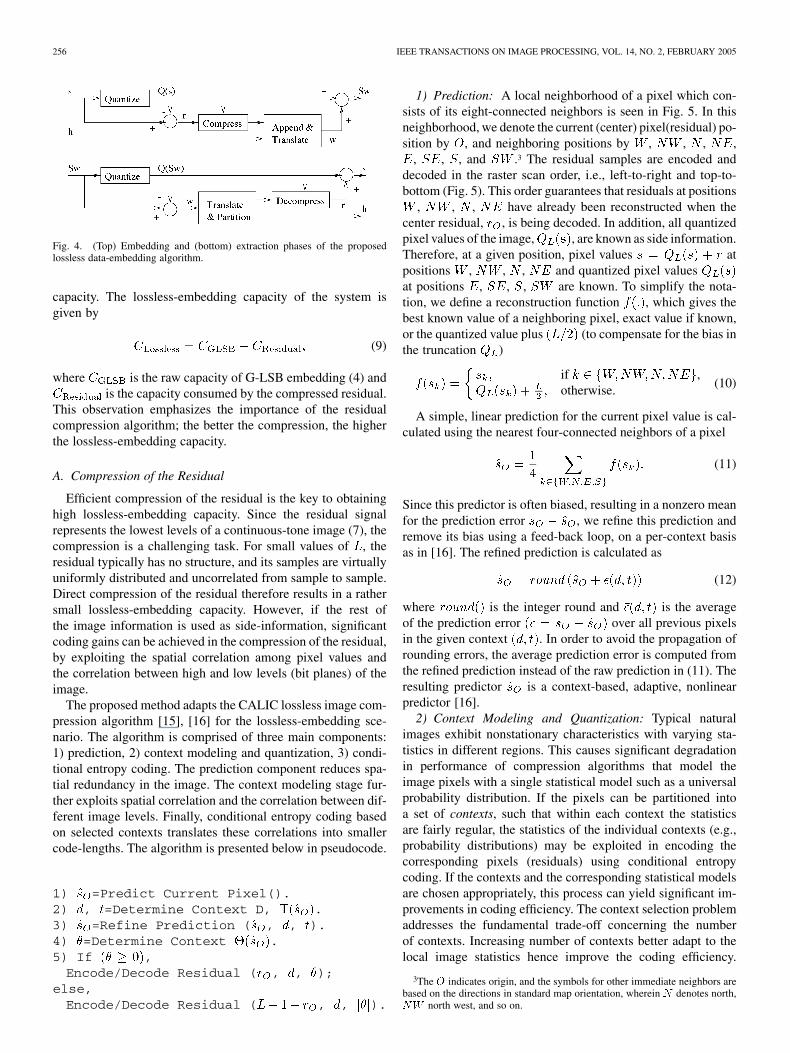
Fig. 4 shows a block diagram of the proposed algorithm. Inthe embedding phase, the host signal is quantized and theresidual is obtained (7). The residual is then compressed inorder to create capacity for the payload data . The compressedresidual and the payload data are concatenated and embeddedinto the host signal via G-LSB modification. In particular, theresulting bit stream is converted to -ary symbols and addedto the quantized host to form the watermarked signal (1).Note that the compression block uses the rest of the host signal,
, as side-information, in order to facilitate better compres-sion and higher capacity.
In the extraction phase, the watermarked signal is quan-tized and the watermark payload (the compressed residual andthe payload data ) is extracted (2). A desirable property of theproposed algorithm is that the payload data extraction is rela-tively simple, and it is independent of the recovery step. If de-sired, the algorithm proceeds with the reconstruction of the orig-inal host . In particular, the residual, , is decompressed using
as side-information. Original host, , is re-constructed by replacing the lowest levels of the watermarkedsignal with the residual (8)
(7)
(8)
Note that the lossless-embedding system has significantlysmaller capacity than the raw G-LSB scheme, since the com-pressed residual typically consumes a large part of the available
256 IEEE TRANSACTIONS ON IMAGE PROCESSING, VOL. 14, NO. 2, FEBRUARY 2005
Fig. 4. (Top) Embedding and (bottom) extraction phases of the proposedlossless data-embedding algorithm.
capacity. The lossless-embedding capacity of the system isgiven by
(9)
where is the raw capacity of G-LSB embedding (4) andis the capacity consumed by the compressed residual.
This observation emphasizes the importance of the residualcompression algorithm; the better the compression, the higherthe lossless-embedding capacity.
A. Compression of the Residual
Efficient compression of the residual is the key to obtaininghigh lossless-embedding capacity. Since the residual signalrepresents the lowest levels of a continuous-tone image (7), thecompression is a challenging task. For small values of , theresidual typically has no structure, and its samples are virtuallyuniformly distributed and uncorrelated from sample to sample.Direct compression of the residual therefore results in a rathersmall lossless-embedding capacity. However, if the rest ofthe image information is used as side-information, significantcoding gains can be achieved in the compression of the residual,by exploiting the spatial correlation among pixel values andthe correlation between high and low levels (bit planes) of theimage.
The proposed method adapts the CALIC lossless image com-pression algorithm [15], [16] for the lossless-embedding sce-nario. The algorithm is comprised of three main components:1) prediction, 2) context modeling and quantization, 3) condi-tional entropy coding. The prediction component reduces spa-tial redundancy in the image. The context modeling stage fur-ther exploits spatial correlation and the correlation between dif-ferent image levels. Finally, conditional entropy coding basedon selected contexts translates these correlations into smallercode-lengths. The algorithm is presented below in pseudocode.
1) =Predict Current Pixel().2) , =Determine Context D, .3) =Refine Prediction ( , , ).4) =Determine Context .5) If ,Encode/Decode Residual ( , , );
else,Encode/Decode Residual ( , , ).
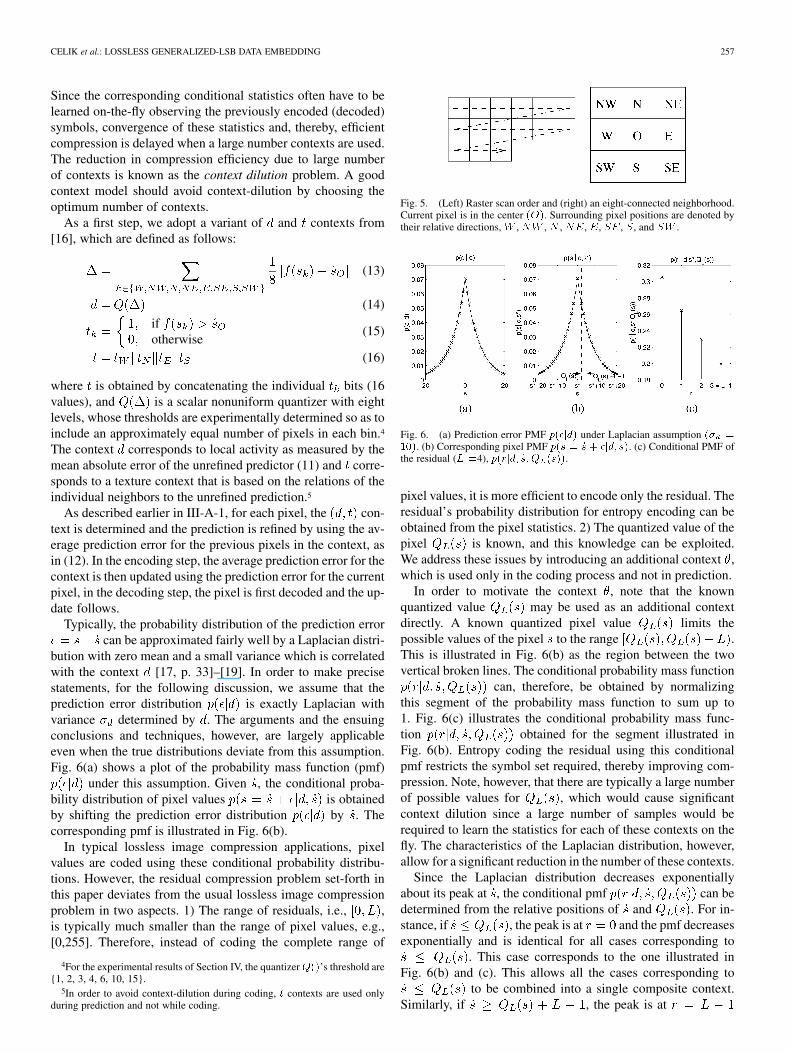
1) Prediction: A local neighborhood of a pixel which con-sists of its eight-connected neighbors is seen in Fig. 5. In thisneighborhood, we denote the current (center) pixel(residual) po-sition by , and neighboring positions by , , , ,
, , , and .3 The residual samples are encoded anddecoded in the raster scan order, i.e., left-to-right and top-to-bottom (Fig. 5). This order guarantees that residuals at positions
, , , have already been reconstructed when thecenter residual, , is being decoded. In addition, all quantizedpixel values of the image, , are known as side information.Therefore, at a given position, pixel values atpositions , , , and quantized pixel valuesat positions , , , are known. To simplify the nota-tion, we define a reconstruction function , which gives thebest known value of a neighboring pixel, exact value if known,or the quantized value plus (to compensate for the bias inthe truncation )
if ,otherwise. (10)
A simple, linear prediction for the current pixel value is cal-culated using the nearest four-connected neighbors of a pixel
(11)
Since this predictor is often biased, resulting in a nonzero meanfor the prediction error , we refine this prediction andremove its bias using a feed-back loop, on a per-context basisas in [16]. The refined prediction is calculated as
(12)
where is the integer round and is the averageof the prediction error over all previous pixelsin the given context . In order to avoid the propagation ofrounding errors, the average prediction error is computed fromthe refined prediction instead of the raw prediction in (11). Theresulting predictor is a context-based, adaptive, nonlinearpredictor [16].
2) Context Modeling and Quantization: Typical naturalimages exhibit nonstationary characteristics with varying sta-tistics in different regions. This causes significant degradationin performance of compression algorithms that model theimage pixels with a single statistical model such as a universalprobability distribution. If the pixels can be partitioned intoa set of contexts, such that within each context the statisticsare fairly regular, the statistics of the individual contexts (e.g.,probability distributions) may be exploited in encoding thecorresponding pixels (residuals) using conditional entropycoding. If the contexts and the corresponding statistical modelsare chosen appropriately, this process can yield significant im-provements in coding efficiency. The context selection problemaddresses the fundamental trade-off concerning the numberof contexts. Increasing number of contexts better adapt to thelocal image statistics hence improve the coding efficiency.
3The O indicates origin, and the symbols for other immediate neighbors arebased on the directions in standard map orientation, wherein N denotes north,NW north west, and so on.
CELIK et al.: LOSSLESS GENERALIZED-LSB DATA EMBEDDING 257
Since the corresponding conditional statistics often have to belearned on-the-fly observing the previously encoded (decoded)symbols, convergence of these statistics and, thereby, efficientcompression is delayed when a large number contexts are used.The reduction in compression efficiency due to large numberof contexts is known as the context dilution problem. A goodcontext model should avoid context-dilution by choosing theoptimum number of contexts.
As a first step, we adopt a variant of and contexts from[16], which are defined as follows:
(13)
(14)
ifotherwise
(15)
(16)
where is obtained by concatenating the individual bits (16values), and is a scalar nonuniform quantizer with eightlevels, whose thresholds are experimentally determined so as toinclude an approximately equal number of pixels in each bin.4
The context corresponds to local activity as measured by themean absolute error of the unrefined predictor (11) and corre-sponds to a texture context that is based on the relations of theindividual neighbors to the unrefined prediction.5
As described earlier in III-A-1, for each pixel, the con-text is determined and the prediction is refined by using the av-erage prediction error for the previous pixels in the context, asin (12). In the encoding step, the average prediction error for thecontext is then updated using the prediction error for the currentpixel, in the decoding step, the pixel is first decoded and the up-date follows.
Typically, the probability distribution of the prediction errorcan be approximated fairly well by a Laplacian distri-
bution with zero mean and a small variance which is correlatedwith the context [17, p. 33]–[19]. In order to make precisestatements, for the following discussion, we assume that theprediction error distribution is exactly Laplacian withvariance determined by . The arguments and the ensuingconclusions and techniques, however, are largely applicableeven when the true distributions deviate from this assumption.Fig. 6(a) shows a plot of the probability mass function (pmf)
under this assumption. Given , the conditional proba-bility distribution of pixel values is obtainedby shifting the prediction error distribution by . Thecorresponding pmf is illustrated in Fig. 6(b).
In typical lossless image compression applications, pixelvalues are coded using these conditional probability distribu-tions. However, the residual compression problem set-forth inthis paper deviates from the usual lossless image compressionproblem in two aspects. 1) The range of residuals, i.e., ,is typically much smaller than the range of pixel values, e.g.,[0,255]. Therefore, instead of coding the complete range of
4For the experimental results of Section IV, the quantizerQ()’s threshold are{1, 2, 3, 4, 6, 10, 15}.
5In order to avoid context-dilution during coding, t contexts are used onlyduring prediction and not while coding.
Fig. 5. (Left) Raster scan order and (right) an eight-connected neighborhood.Current pixel is in the center (O). Surrounding pixel positions are denoted bytheir relative directions, W , NW , N , NE, E, SE, S, and SW .
Fig. 6. (a) Prediction error PMF p(�jd) under Laplacian assumption (� =10). (b) Corresponding pixel PMF p(s = _s + �jd; _s). (c) Conditional PMF ofthe residual (L =4), p(rjd; _s;Q (s)).
pixel values, it is more efficient to encode only the residual. Theresidual’s probability distribution for entropy encoding can beobtained from the pixel statistics. 2) The quantized value of thepixel is known, and this knowledge can be exploited.We address these issues by introducing an additional context ,which is used only in the coding process and not in prediction.
In order to motivate the context , note that the knownquantized value may be used as an additional contextdirectly. A known quantized pixel value limits thepossible values of the pixel to the range .This is illustrated in Fig. 6(b) as the region between the twovertical broken lines. The conditional probability mass function
can, therefore, be obtained by normalizingthis segment of the probability mass function to sum up to1. Fig. 6(c) illustrates the conditional probability mass func-tion obtained for the segment illustrated inFig. 6(b). Entropy coding the residual using this conditionalpmf restricts the symbol set required, thereby improving com-pression. Note, however, that there are typically a large numberof possible values for , which would cause significantcontext dilution since a large number of samples would berequired to learn the statistics for each of these contexts on thefly. The characteristics of the Laplacian distribution, however,allow for a significant reduction in the number of these contexts.
Since the Laplacian distribution decreases exponentiallyabout its peak at , the conditional pmf can bedetermined from the relative positions of and . For in-stance, if , the peak is at and the pmf decreasesexponentially and is identical for all cases corresponding to
. This case corresponds to the one illustrated inFig. 6(b) and (c). This allows all the cases corresponding to
to be combined into a single composite context.Similarly, if , the peak is at
258 IEEE TRANSACTIONS ON IMAGE PROCESSING, VOL. 14, NO. 2, FEBRUARY 2005
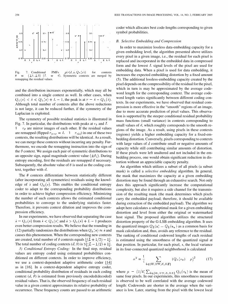
Fig. 7. Conditional PMFs p(rjd; _s; Q (s)) for contexts� = f�1;�2g (L = 4). Symmetric contexts are merged byremapping the residual values.
and the distribution increases exponentially, which may all becombined into a single context as well. In other cases, when
, the peak is at .Although total number of contexts after the above reductionsis not large, it can be reduced further, if the symmetry of theLaplacian is exploited.
The symmetry of possible residual statistics is illustrated inFig. 7. In particular, the distributions with peaks at and
are mirror images of each other. If the residual valuesare remapped (flipped ) in one of these twocontexts, the resulting distributions will be identical. As a result,we can merge these contexts without incurring any penalty. Fur-thermore, we encode the remapping instruction into the sign ofthe context. We assign each pair of symmetric distributions toan opposite sign, equal magnitude context value . Duringentropy encoding, first the residuals are remapped if necessary.Subsequently, the absolute value of is used as the coding con-text, together with .
The contexts differentiate between statistically different(after incorporating all symmetries) residuals using the knowl-edge of and . This enables the conditional entropycoder to adapt to the corresponding probability distributionsin order to achieve higher compression efficiency. Minimizingthe number of such contexts allows the estimated conditionalprobabilities to converge to the underlying statistics faster.Therefore, it prevents context dilution and improves the com-pression efficiency.
In our experiments, we have observed that separating the casefrom and produces
even better compression results. We believe that the rounding in(12) partially randomizes the distributions when andcauses this phenomenon. When the corresponding new contextsare created, total number of contexts equals .The total number of coding contexts ( , ) is .
3) Conditional Entropy Coding: In the final step, residualvalues are entropy coded using estimated probabilities con-ditioned on different contexts. In order to improve efficiency,we use a context-dependent adaptive arithmetic coder [14]as in [16]. In a context-dependent adaptive entropy coder,conditional probability distribution of residuals in each codingcontext ( , ) is estimated from previously encoded(decoded)residual values. That is, the observed frequency of each residualvalue in a given context approximates its relative probability ofoccurrence. These frequency counts are passed to an arithmetic
coder which allocates best code-lengths corresponding to givensymbol probabilities.
B. Selective Embedding and Compression
In order to maximize lossless data-embedding capacity for agiven embedding level, the algorithm presented above utilizesevery pixel in a given image, i.e., the residual for each pixel isreplaced and incorporated in the embedded data in compressedform and the lowest signal levels of the pixel are used forembedding data. When a pixel is used for data embedding, itincreases the expected embedding distortion by a fixed amount(5). The additional lossless-embedding capacity created by thepixel depends on the compressibility of the residual for the pixel,which in turn is may be approximated by the average code-word length for the corresponding context. The average code-word length varies significantly between different coding con-texts. In our experiments, we have observed that residual com-pression is more effective in the “smooth” regions of an image,due to more accurate prediction of pixel values. This observa-tion is supported by the steeper conditional residual probabilitymass functions (small variance) in contexts corresponding tosmall values of , which roughly corresponds to the smooth re-gions of the image. As a result, using pixels in these contexts(regions) yields a higher embedding capacity for a fixed-em-bedding distortion. Conversely, pixels corresponding to contextswith large values of contribute small or negative amounts ofcapacity while still contributing similar amounts of distortion.If these pixels were left unaltered and not included in the em-bedding process, one would obtain significant reduction in dis-tortion without an appreciable capacity penalty.
An algorithm which utilizes a subset of all pixels (a subsetmask) is called a selective embedding algorithm. In general,the mask that maximizes the capacity at a given embeddingdistortion may be found through an exhaustive search. Not onlydoes this approach significantly increase the computationalcomplexity, but also it requires a side channel for the transmis-sion of the resulting mask (the mask determines which pixelscarry the embedded payload; therefore, it should be availableduring extraction of the embedded payload). The algorithm weadopt here calculates a suboptimal mask for a given embeddingdistortion and level from either the original or watermarkedhost signal. The proposed algorithm utilizes the structureddistortion property of the G-LSB embedding algorithm. It usesthe quantized images as a common basis formask calculation and, thus, avoids any reference to the residual.The ranking of conditional codeword lengths of each residualis estimated using the smoothness of the quantized signal atthat position. In particular, for each pixel, , the local variancein its four-connected quantized neighborhood is calculated
(17)
where is the mean ofsame four pixels. In our experiments, this smoothness measureis observed to be well correlated with the average codewordlength: Codewords are shorter in the average when the vari-ance is low. Later, starting from the pixel with the lowest local
CELIK et al.: LOSSLESS GENERALIZED-LSB DATA EMBEDDING 259
variance, specified number of pixels are assigned to the mask.This assignment process can be simplified by collecting a his-togram of variance values and determining a threshold wheregiven number of pixels have a lower variance. Then, each pixelis assigned to the mask if its variance is less than the threshold.In practice, a discrete histogram of variance values is collected.Discrete valued histogram bins may lead to a threshold valuewhich assigns more pixels to the mask than the number speci-fied by the distortion. In this case, the assignment procedure iscarried out in two passes. In the first pass, all pixels below thethreshold except the ones which belong to the histogram bin im-mediately before the threshold are assigned to the mask. In thesecond pass, excluded pixels are traversed in a particular scanorder and assigned to the mask until total number of pixels inthe mask matches the specified number. Since this process usesthe quantized images which are not modified by the data em-bedding, i.e., , for a given embedding distor-tion, the results of the mask selection are identical for the em-bedding and extraction processes ensuring that synchronism ismaintained.
This extension improves the capacity-distortion performanceof the original algorithm, at the expense of increased computa-tional burden of calculating the mask.
C. Capacity Control
Thus far, we have concentrated on maximizing the lossless-embedding capacity given an embedding level and a target dis-tortion. In most practical applications, however, the complemen-tary problem is of interest, where the goal is to determine the em-bedding level and mask which result in the least possible distor-tion, while providing the given target capacity. As the capacityconsumed by the compressed residuals—thus, the lossless-em-bedding capacity—varies with the underlying image statistics,it is not possible to accurately estimate the embedding level anddistortion from the target capacity.
A more suitable approach that is utilized here, is to vary theembedding level and the target distortion in the method ofSection III-B so as to achieve the desired capacity. In order toallow extraction and recovery, the embedding level , and thefinal target distortion must be communicated to the receiver.This is achieved by modifying LSBs of a small number of pixelsat fixed positions, say first pixels, which are excluded duringthe lossless-embedding phase. In order to ensure recovery, theoriginal LSBs of these pixels are transmitted as a part of thepayload. In order to limit the required through-put from thisadditional channel, only a limited set of level-distortion pairsare used. After obtaining the level and distortion parametersthrough the additional fixed channel, the extraction algorithmcalculates the embedding mask which maximizes the embed-ding capacity as outlined in Section III-B. As a result, the ca-pacity-control problem, i.e., minimizing the distortion given atarget capacity at the embedding phase, is reduced to finding theembedding level-distortion pair (from a limited set of such pairs)which has the minimum distortion and satisfies the capacity re-quirement. The achievable capacity of a given level-distortionpair is obtained by compressing the residual and calculating theG-LSB embedding capacity with the given parameters. An it-erative algorithm, which searches through level-distortion pairs
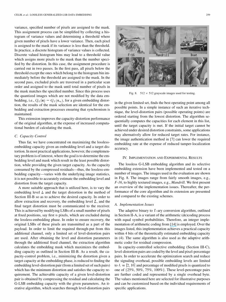
Fig. 8. 512 � 512 grayscale images used for testing.
in the given limited set, finds the best operating point among allpossible points. In a simple instance of such an iterative tech-nique, the level-distortion pairs (possible operating points) areordered starting from the lowest distortion. The algorithm se-quentially computes the capacities for each element in this list,until the target capacity is met. If the initial target cannot beachieved under desired distortion constraints, some applicationsmay alternatively allow for reduced target rates. For instance,the image authentication method in [7] can lower the requiredembedding rate at the expense of reduced tamper-localizationaccuracy.
IV. IMPLEMENTATION AND EXPERIMENTAL RESULTS
The lossless G-LSB embedding algorithm and its selectiveembedding extension have been implemented and tested on anumber of images. The images used in the evaluation are shownin Fig. 8. The images range from fairly smooth images, e.g.,F-16, to highly textured images, e.g., Mandrill. We first presentan overview of the implementation issues. Thereafter, the per-formance of the core algorithm and its extension are presentedand compared to the existing schemes.
A. Implementation Issues
The adaptive binary to -ary conversion algorithm, outlinedin Section II-A, is a variant of the arithmetic (de)coding processwith equal symbol probabilities. Therefore, an integer imple-mentation of arithmetic coding from [14] is employed. Over theimages listed, this implementation achieves a practical capacitywithin 4 bits of the theoretically estimated embedding capacityin (4). The same algorithm is also used as the adaptive arith-metic coder for residual compression.
In capacity-controlled selective embedding (Section III-C),level-distortion pairs are coded by the level and pixel-percentagepairs. In order to accelerate the optimization search and reducethe signaling overhead, possible embedding levels are limitedto and percentage of modified pixels is quantized toone of {25%, 50%, 75%, 100%}. These level-percentage pairsare further coded and represented by a single overhead byte.The values mentioned here are selected for illustrative purposesand can be customized based on the individual requirements ofspecific applications.
260 IEEE TRANSACTIONS ON IMAGE PROCESSING, VOL. 14, NO. 2, FEBRUARY 2005
In order to guarantee flawless operation, we define a simpleprotocol and an associated syntax for the embedded payload.First, the overhead byte representing the embedding parame-ters is embedded in the LSBs of first eight pixels of the rasterscan order. The original values of these pixel LSBs are bufferedand these positions are excluded in any subsequent embeddingmask. Payload to be embedded using the G-LSB algorithm con-sists of four parts: 1) length of message data in bytes, 2) mes-sage data, 3) buffered LSBs, and 4) compressed residual de-scription. The length of the message data is represented by twobytes allowing for a maximum length of 64 K bytes (a vari-able size length descriptor can be utilized if message data is ex-pected to be larger). The length of the compressed descriptionis not specified since the total number of coded symbols (resid-uals) is defined by the pixel-percentage parameter. The pay-load data constructed according to this syntax is embedded intothe image using G-LSB embedding algorithm. A total of threebytes, two-byte length, plus the overhead byte, is the overalloverhead. In applications where a fixed-length message is em-bedded, the overhead can be reduced accordingly.
B. Experimental Results
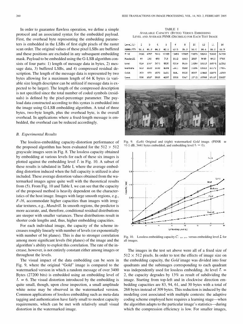
The lossless-embedding capacity-distortion performance ofthe proposed algorithm has been evaluated for the 512 512grayscale images seen in Fig. 8. The lossless capacity obtainedby embedding at various levels for each of these six images isplotted against the embedding level in Fig. 10. A subset ofthese results is tabulated in Table I, where the average embed-ding distortion induced when the full capacity is utilized is alsoincluded. These average distortion values obtained from the wa-termarked images agree quite well with the theoretical resultsfrom (5). From Fig. 10 and Table I, we can see that the capacityof the proposed method is heavily dependent on the character-istics of the host image. Images with large smooth regions, e.g.,F-16, accommodate higher capacities than images with irreg-ular textures, e.g., Mandrill. In smooth regions, the predictor ismore accurate, and, therefore, conditional residual distributionsare steeper with smaller variances. These distributions result inshorter code lengths and, thus, higher embedding capacities.
For each individual image, the capacity of the scheme in-creases roughly linearly with number of levels (or exponentiallywith number of bit planes). This is due to stronger correlationamong more significant levels (bit planes) of the image and thealgorithm’s ability to exploit this correlation. The rate of the in-crease, however, is not entirely constant either among images orthroughout the levels.
The visual impact of the data embedding can be seen inFig. 9, where the original “Gold” image is compared to thewatermarked version in which a random message of over 3400Bytes (27200 bits) is embedded using an embedding level of
6. The visual distortion introduced by the embedding isquite small, though, upon close inspection, a small amplitudewhite noise may be observed in the watermarked version.Common applications of lossless embedding such as meta-datatagging and authentication have fairly small to modest capacityrequirements, which can be met with relatively small visualdistortion in the watermarked image.
TABLE IAVAILABLE CAPACITY (BYTES) VERSUS EMBEDDING
LEVEL AND AVERAGE PSNR (DECIBELS) FOR EACH TEST IMAGE
Fig. 9. (Left) Original and (right) watermarked Gold image. (PSNR =
40:5 dB, 3441 bytes embedded, and embedding level L = 6).
Fig. 10. Lossless embedding capacity C versus embedding levelL forall images.
The images in the test set above were all of a fixed size of512 512 pixels. In order to test the effects of image size onthe embedding capacity, the Gold image was divided into fourquadrants and the subimages corresponding to each quadrantwas independently used for lossless embedding. At level2, the capacity degrades by 13% as result of subdividing theimage. Starting from top-left and in clockwise direction em-bedding capacities are 83, 94, 61, and 30 bytes with a total of268 bytes instead of 309 bytes. This reduction is induced by themodeling cost associated with multiple contexts: the adaptivecoding scheme employed here requires a learning stage—whenthe algorithm adapts to the particular image’s statistics—duringwhich the compression efficiency is low. For smaller images,
CELIK et al.: LOSSLESS GENERALIZED-LSB DATA EMBEDDING 261
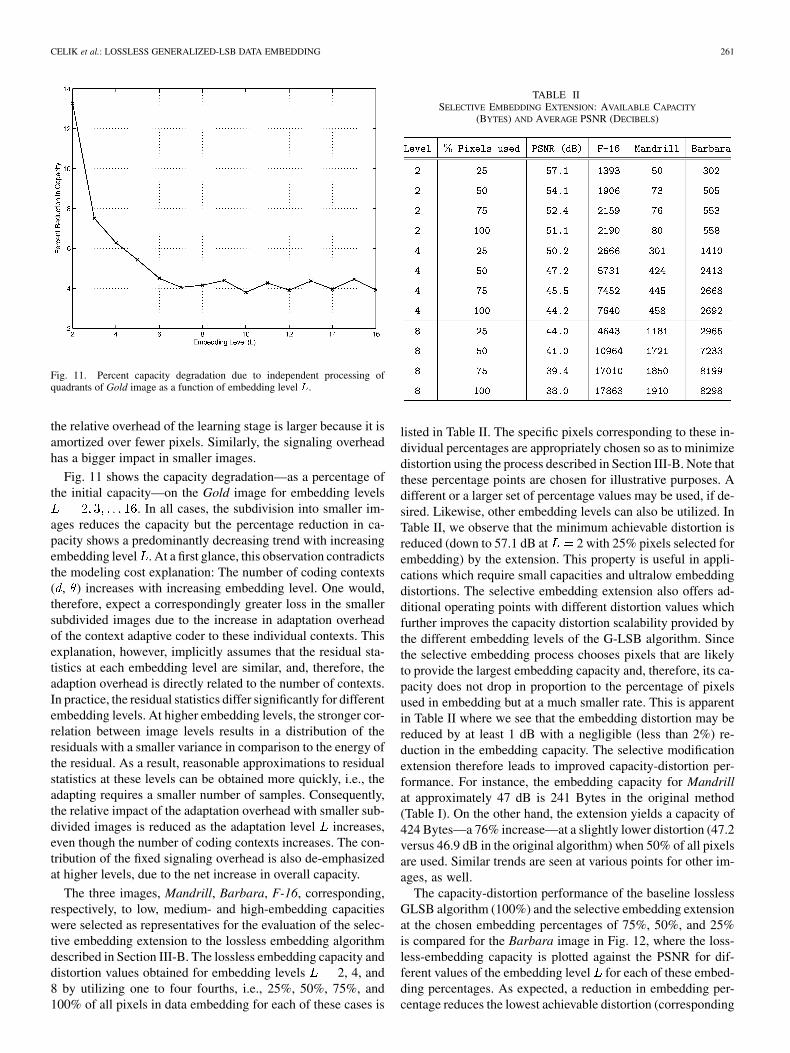
Fig. 11. Percent capacity degradation due to independent processing ofquadrants of Gold image as a function of embedding level L.
the relative overhead of the learning stage is larger because it isamortized over fewer pixels. Similarly, the signaling overheadhas a bigger impact in smaller images.
Fig. 11 shows the capacity degradation—as a percentage ofthe initial capacity—on the Gold image for embedding levels
. In all cases, the subdivision into smaller im-ages reduces the capacity but the percentage reduction in ca-pacity shows a predominantly decreasing trend with increasingembedding level . At a first glance, this observation contradictsthe modeling cost explanation: The number of coding contexts( , ) increases with increasing embedding level. One would,therefore, expect a correspondingly greater loss in the smallersubdivided images due to the increase in adaptation overheadof the context adaptive coder to these individual contexts. Thisexplanation, however, implicitly assumes that the residual sta-tistics at each embedding level are similar, and, therefore, theadaption overhead is directly related to the number of contexts.In practice, the residual statistics differ significantly for differentembedding levels. At higher embedding levels, the stronger cor-relation between image levels results in a distribution of theresiduals with a smaller variance in comparison to the energy ofthe residual. As a result, reasonable approximations to residualstatistics at these levels can be obtained more quickly, i.e., theadapting requires a smaller number of samples. Consequently,the relative impact of the adaptation overhead with smaller sub-divided images is reduced as the adaptation level increases,even though the number of coding contexts increases. The con-tribution of the fixed signaling overhead is also de-emphasizedat higher levels, due to the net increase in overall capacity.
The three images, Mandrill, Barbara, F-16, corresponding,respectively, to low, medium- and high-embedding capacitieswere selected as representatives for the evaluation of the selec-tive embedding extension to the lossless embedding algorithmdescribed in Section III-B. The lossless embedding capacity anddistortion values obtained for embedding levels 2, 4, and8 by utilizing one to four fourths, i.e., 25%, 50%, 75%, and100% of all pixels in data embedding for each of these cases is
TABLE IISELECTIVE EMBEDDING EXTENSION: AVAILABLE CAPACITY
(BYTES) AND AVERAGE PSNR (DECIBELS)
listed in Table II. The specific pixels corresponding to these in-dividual percentages are appropriately chosen so as to minimizedistortion using the process described in Section III-B. Note thatthese percentage points are chosen for illustrative purposes. Adifferent or a larger set of percentage values may be used, if de-sired. Likewise, other embedding levels can also be utilized. InTable II, we observe that the minimum achievable distortion isreduced (down to 57.1 dB at 2 with 25% pixels selected forembedding) by the extension. This property is useful in appli-cations which require small capacities and ultralow embeddingdistortions. The selective embedding extension also offers ad-ditional operating points with different distortion values whichfurther improves the capacity distortion scalability provided bythe different embedding levels of the G-LSB algorithm. Sincethe selective embedding process chooses pixels that are likelyto provide the largest embedding capacity and, therefore, its ca-pacity does not drop in proportion to the percentage of pixelsused in embedding but at a much smaller rate. This is apparentin Table II where we see that the embedding distortion may bereduced by at least 1 dB with a negligible (less than 2%) re-duction in the embedding capacity. The selective modificationextension therefore leads to improved capacity-distortion per-formance. For instance, the embedding capacity for Mandrillat approximately 47 dB is 241 Bytes in the original method(Table I). On the other hand, the extension yields a capacity of424 Bytes—a 76% increase—at a slightly lower distortion (47.2versus 46.9 dB in the original algorithm) when 50% of all pixelsare used. Similar trends are seen at various points for other im-ages, as well.
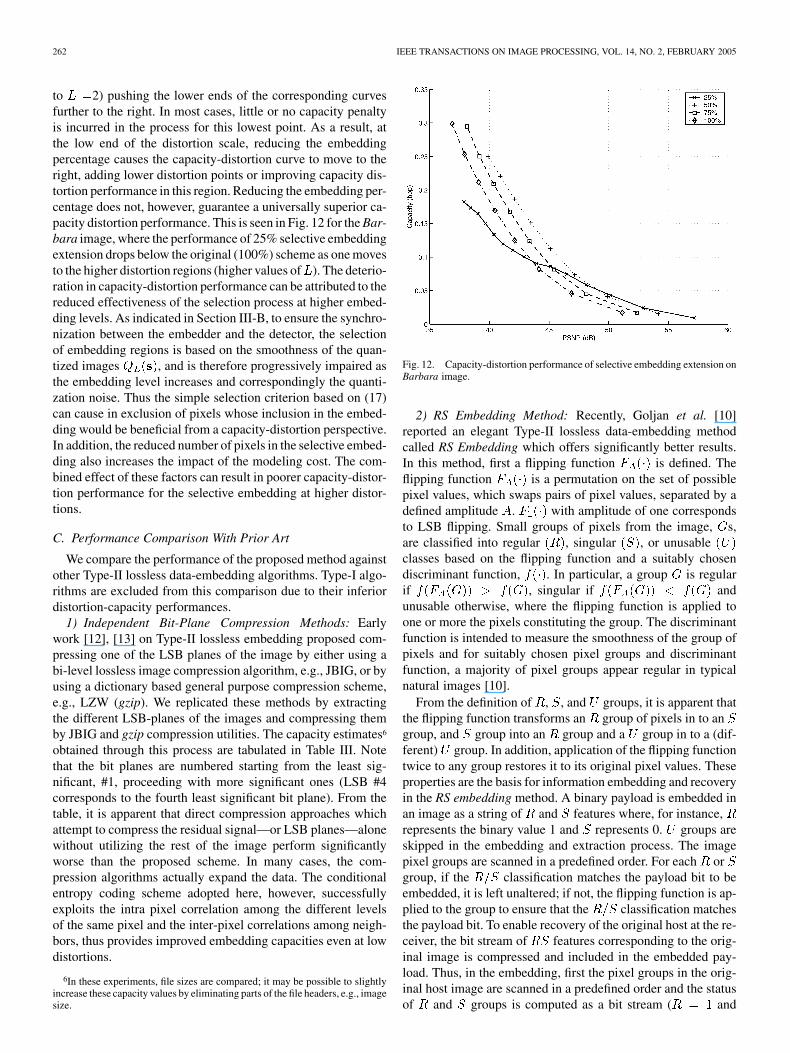
The capacity-distortion performance of the baseline losslessGLSB algorithm (100%) and the selective embedding extensionat the chosen embedding percentages of 75%, 50%, and 25%is compared for the Barbara image in Fig. 12, where the loss-less-embedding capacity is plotted against the PSNR for dif-ferent values of the embedding level for each of these embed-ding percentages. As expected, a reduction in embedding per-centage reduces the lowest achievable distortion (corresponding
262 IEEE TRANSACTIONS ON IMAGE PROCESSING, VOL. 14, NO. 2, FEBRUARY 2005
to 2) pushing the lower ends of the corresponding curvesfurther to the right. In most cases, little or no capacity penaltyis incurred in the process for this lowest point. As a result, atthe low end of the distortion scale, reducing the embeddingpercentage causes the capacity-distortion curve to move to theright, adding lower distortion points or improving capacity dis-tortion performance in this region. Reducing the embedding per-centage does not, however, guarantee a universally superior ca-pacity distortion performance. This is seen in Fig. 12 for the Bar-bara image, where the performance of 25% selective embeddingextension drops below the original (100%) scheme as one movesto the higher distortion regions (higher values of ). The deterio-ration in capacity-distortion performance can be attributed to thereduced effectiveness of the selection process at higher embed-ding levels. As indicated in Section III-B, to ensure the synchro-nization between the embedder and the detector, the selectionof embedding regions is based on the smoothness of the quan-tized images , and is therefore progressively impaired asthe embedding level increases and correspondingly the quanti-zation noise. Thus the simple selection criterion based on (17)can cause in exclusion of pixels whose inclusion in the embed-ding would be beneficial from a capacity-distortion perspective.In addition, the reduced number of pixels in the selective embed-ding also increases the impact of the modeling cost. The com-bined effect of these factors can result in poorer capacity-distor-tion performance for the selective embedding at higher distor-tions.
C. Performance Comparison With Prior Art
We compare the performance of the proposed method againstother Type-II lossless data-embedding algorithms. Type-I algo-rithms are excluded from this comparison due to their inferiordistortion-capacity performances.
1) Independent Bit-Plane Compression Methods: Earlywork [12], [13] on Type-II lossless embedding proposed com-pressing one of the LSB planes of the image by either using abi-level lossless image compression algorithm, e.g., JBIG, or byusing a dictionary based general purpose compression scheme,e.g., LZW (gzip). We replicated these methods by extractingthe different LSB-planes of the images and compressing themby JBIG and gzip compression utilities. The capacity estimates6
obtained through this process are tabulated in Table III. Notethat the bit planes are numbered starting from the least sig-nificant, #1, proceeding with more significant ones (LSB #4corresponds to the fourth least significant bit plane). From thetable, it is apparent that direct compression approaches whichattempt to compress the residual signal—or LSB planes—alonewithout utilizing the rest of the image perform significantlyworse than the proposed scheme. In many cases, the com-pression algorithms actually expand the data. The conditionalentropy coding scheme adopted here, however, successfullyexploits the intra pixel correlation among the different levelsof the same pixel and the inter-pixel correlations among neigh-bors, thus provides improved embedding capacities even at lowdistortions.
6In these experiments, file sizes are compared; it may be possible to slightlyincrease these capacity values by eliminating parts of the file headers, e.g., imagesize.
Fig. 12. Capacity-distortion performance of selective embedding extension onBarbara image.
2) RS Embedding Method: Recently, Goljan et al. [10]reported an elegant Type-II lossless data-embedding methodcalled RS Embedding which offers significantly better results.In this method, first a flipping function is defined. Theflipping function is a permutation on the set of possiblepixel values, which swaps pairs of pixel values, separated by adefined amplitude . with amplitude of one correspondsto LSB flipping. Small groups of pixels from the image, s,are classified into regular , singular , or unusableclasses based on the flipping function and a suitably chosendiscriminant function, . In particular, a group is regularif , singular if andunusable otherwise, where the flipping function is applied toone or more the pixels constituting the group. The discriminantfunction is intended to measure the smoothness of the group ofpixels and for suitably chosen pixel groups and discriminantfunction, a majority of pixel groups appear regular in typicalnatural images [10].
From the definition of , , and groups, it is apparent thatthe flipping function transforms an group of pixels in to angroup, and group into an group and a group in to a (dif-ferent) group. In addition, application of the flipping functiontwice to any group restores it to its original pixel values. Theseproperties are the basis for information embedding and recoveryin the RS embedding method. A binary payload is embedded inan image as a string of and features where, for instance,represents the binary value 1 and represents 0. groups areskipped in the embedding and extraction process. The imagepixel groups are scanned in a predefined order. For each orgroup, if the classification matches the payload bit to beembedded, it is left unaltered; if not, the flipping function is ap-plied to the group to ensure that the classification matchesthe payload bit. To enable recovery of the original host at the re-ceiver, the bit stream of features corresponding to the orig-inal image is compressed and included in the embedded pay-load. Thus, in the embedding, first the pixel groups in the orig-inal host image are scanned in a predefined order and the statusof and groups is computed as a bit stream ( and
CELIK et al.: LOSSLESS GENERALIZED-LSB DATA EMBEDDING 263
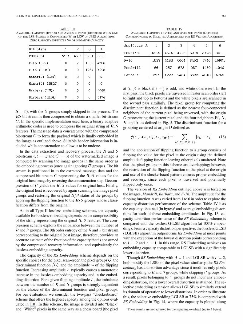
TABLE IIIAVAILABLE CAPACITY (BYTES) AND AVERAGE PSNR (DECIBELS) WHEN ONE
OF THE LSB-PLANES IS COMPRESSED WITH LZW OR JBIG ALGORITHMS.ZERO CAPACITY INDICATES NO OR NEGATIVE CAPACITY
), with the groups simply skipped in the process. Thebit stream is then compressed to obtain a smaller bit-stream
. In the specific implementation used here, a binary adaptivearithmetic coder is used to compress the original string of ,features. The message data is concatenated with the compressedbit-stream to form the payload which is finally embedded inthe image as outlined above. Suitable header information is in-cluded while concatenation to allow it to be undone.
In the data extraction and recovery process, the andbit-stream ( and ) of the watermarked image iscomputed by scanning the image groups in the same order asthe embedding process (once again ignoring groups). The bitstream is partitioned in to the extracted message data and thecompressed bit-stream representing the , values for theoriginal host image by reversing the concatenation step. Decom-pression of yields the , values for original host. Finally,the original host is recovered by again scanning the image pixelgroups and restoring the original status of the groups byapplying the flipping function to the groups whose classi-fication differs from the original.
As in all Type-II lossless-embedding schemes, the capacityavailable for lossless embedding depends on the compressibilityof the string representing the original , features. The com-pression scheme exploits the imbalance between the number of
and groups. The 0th order entropy of the and bit streamcorresponding to the original host image, therefore, provides anaccurate estimate of the fraction of the capacity that is consumedby the compressed recovery information, and equivalently thelossless-embedding capacity.
The capacity of the RS Embedding scheme depends on thespecific choices for the pixel scan-order, the pixel groups , thediscriminant function , and the amplitude of the flippingfunction. Increasing amplitude typically causes a monotonicincrease in the lossless-embedding capacity and in the embed-ding distortion. For a given flipping amplitude , the imbalancebetween the number of and groups is strongly dependenton the choice of the discriminant function and pixel groups.For our evaluation, we consider the two-pass “checkerboard”scheme that offers the highest capacity among the options eval-uated in [10]. In this scheme, the image is divided into “Black”and “White” pixels in the same way as a chess board [the pixel
TABLE IVAVAILABLE CAPACITY (BYTES) AND AVERAGE PSNR (DECIBELS)
CORRESPONDING TO SELECTED AMPLITUDES FOR RS VECTOR ALGORITHM
at ( , ) is black if is odd, and white otherwise]. In thefirst pass, the black pixels are traversed in raster scan order (leftto right and top to bottom) and the white pixels are scanned inthe second pass similarly. The pixel group for computing thediscriminant function is defined as the nearest four-connectedneighbors of the current pixel being traversed, with the origin
representing the current pixel and the four neighbors , ,, and , as defined in Fig. 5. The discriminant function for a
grouping centered at origin defined as
(18)
and the application of flipping function to a group consists offlipping the value for the pixel at the origin using the definedamplitude flipping function leaving other pixels unaltered. Notethat the pixel groups in this scheme are overlapping; however,the restriction of the flipping function to the pixel at the originand use of the checkerboard pattern ensures proper embeddingand recovery, since each pixel is traversed and potentiallyflipped only once.
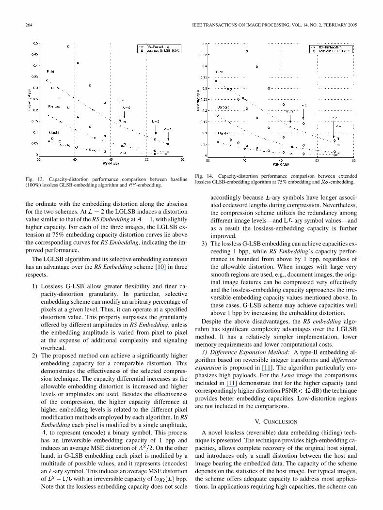
The version of RS Embedding outlined above was tested onthe images, Mandrill, Barbara, and F-16. The amplitude for theflipping function was varied from 1 to 6 in order to explore thecapacity-distortion performance of the scheme. Table IV liststhe capacity obtained (in bytes)7 and average embedding distor-tions for each of these embedding amplitudes. In Fig. 13, ca-pacity-distortion performance of the RS Embedding scheme iscompared with the lossless G-LSB algorithm (at 100% embed-ding). From a capacity distortion perspective, the lossless GLSB(LGLSB) algorithm outperforms RS Embedding at most pointswith the exception of the lowest distortion points correspondingto 2 and 1. In this range, RS Embedding achieves anembedding capacity comparable to LGLSB with a significantlylower distortion.
Though RS Embedding with 1 and LGLSB with 2,both modify the LSBs of the pixel values similarly, the RS Em-bedding has a distortion advantage since it modifies only pixelscorresponding to and groups, while skipping groups. Asa result, pixels belonging to groups do not incur any embed-ding distortion, and a lower overall distortion is attained. The se-lective embedding extension allows LGLSB to similarly extendits domain of operation to lower distortions. In order to illustratethis, the selective embedding LGLSB at 75% is compared withRS Embedding in Fig. 14, where the capacity is plotted along
7These results are not adjusted for the signaling overhead (up to 3 bytes).
264 IEEE TRANSACTIONS ON IMAGE PROCESSING, VOL. 14, NO. 2, FEBRUARY 2005
Fig. 13. Capacity-distortion performance comparison between baseline(100%) lossless GLSB-embedding algorithm and RS-embedding.
the ordinate with the embedding distortion along the abscissafor the two schemes. At 2 the LGLSB induces a distortionvalue similar to that of the RS Embedding at 1, with slightlyhigher capacity. For each of the three images, the LGLSB ex-tension at 75% embedding capacity distortion curves lie abovethe corresponding curves for RS Embedding, indicating the im-proved performance.
The LGLSB algorithm and its selective embedding extensionhas an advantage over the RS Embedding scheme [10] in threerespects.
1) Lossless G-LSB allow greater flexibility and finer ca-pacity-distortion granularity. In particular, selectiveembedding scheme can modify an arbitrary percentage ofpixels at a given level. Thus, it can operate at a specifieddistortion value. This property surpasses the granularityoffered by different amplitudes in RS Embedding, unlessthe embedding amplitude is varied from pixel to pixelat the expense of additional complexity and signalingoverhead.
2) The proposed method can achieve a significantly higherembedding capacity for a comparable distortion. Thisdemonstrates the effectiveness of the selected compres-sion technique. The capacity differential increases as theallowable embedding distortion is increased and higherlevels or amplitudes are used. Besides the effectivenessof the compression, the higher capacity difference athigher embedding levels is related to the different pixelmodification methods employed by each algorithm. In RSEmbedding each pixel is modified by a single amplitude,
, to represent (encode) a binary symbol. This processhas an irreversible embedding capacity of 1 bpp andinduces an average MSE distortion of . On the otherhand, in G-LSB embedding each pixel is modified by amultitude of possible values, and it represents (encodes)an -ary symbol. This induces an average MSE distortionof with an irreversible capacity of bpp.Note that the lossless embedding capacity does not scale
Fig. 14. Capacity-distortion performance comparison between extendedlossless GLSB-embedding algorithm at 75% embedding and RS-embedding.
accordingly because -ary symbols have longer associ-ated codeword lengths during compression. Nevertheless,the compression scheme utilizes the redundancy amongdifferent image levels—and L -ary symbol values—andas a result the lossless-embedding capacity is furtherimproved.
3) The lossless G-LSB embedding can achieve capacities ex-ceeding 1 bpp, while RS Embedding’s capacity perfor-mance is bounded from above by 1 bpp, regardless ofthe allowable distortion. When images with large verysmooth regions are used, e.g., document images, the orig-inal image features can be compressed very effectivelyand the lossless-embedding capacity approaches the irre-versible-embedding capacity values mentioned above. Inthese cases, G-LSB scheme may achieve capacities wellabove 1 bpp by increasing the embedding distortion.
Despite the above disadvantages, the RS embedding algo-rithm has significant complexity advantages over the LGLSBmethod. It has a relatively simpler implementation, lowermemory requirements and lower computational costs.
3) Difference Expansion Method: A type-II embedding al-gorithm based on reversible integer transforms and differenceexpansion is proposed in [11]. The algorithm particularly em-phasizes high payloads. For the Lena image the comparisonsincluded in [11] demonstrate that for the higher capacity (andcorrespondingly higher distortion PSNR dB) the techniqueprovides better embedding capacities. Low-distortion regionsare not included in the comparisons.
V. CONCLUSION
A novel lossless (reversible) data embedding (hiding) tech-nique is presented. The technique provides high-embedding ca-pacities, allows complete recovery of the original host signal,and introduces only a small distortion between the host andimage bearing the embedded data. The capacity of the schemedepends on the statistics of the host image. For typical images,the scheme offers adequate capacity to address most applica-tions. In applications requiring high capacities, the scheme can
CELIK et al.: LOSSLESS GENERALIZED-LSB DATA EMBEDDING 265
be modified to adjust the embedding parameters to meet the ca-pacity requirements, thus trading off intermediate distortion forincreased capacity. In such scenarios, the G-LSB embeddingproposed in the current paper is significantly advantaged overconventional LSB-embedding techniques because it offers finergrain scalability along the capacity distortion curve. The per-formance of the algorithm—and its extensions—is rigorouslytested with representative images and compared with the ear-lier methods. The proposed algorithm is shown to out-performbit-plane compression and RS embedding methods, especiallyat moderate- to high-distortion regions.
REFERENCES
[1] R. L. Lagendijk, G. C. Langelaar, and I. Setyawan, “Watermarking dig-ital image and video data,” IEEE Signal Process. Mag., vol. 17, no. 5,pp. 20–46, Sep. 2000.
[2] F. Hartung and M. Kutter, “Multimedia watermarking techniques,” Proc.IEEE, vol. 87, no. 7, pp. 1079–1107, Jul. 1999.
[3] M. D. Swanson, M. Kobayashi, and A. H. Tewfik, “Multimedia data-embedding and watermarking technologies,” Proc. IEEE, vol. 86, no. 6,pp. 1064–1087, Jun. 1998.
[4] M. U. Celik, G. Sharma, E. Saber, and A. M. Tekalp, “A hierarchicalimage authentication watermark with improved localization and secu-rity,” in Proc. IEEE ICIP, Thessaloniki, Greece, Oct. 2001, pp. 502–505.
[5] , “Hierarchical watermarking for secure image authentication withlocalization,” IEEE Trans. Image Process., vol. 11, no. 6, Jun. 2002.
[6] National Electrical Manufacturers Association (NEMA), DigitalImaging and Communications in Medicine (DICOM), 2003.
[7] M. U. Celik, G. Sharma, A. M. Tekalp, and E. Saber, “Localized losslessauthentication watermark (LAW),” Proc. SPIE, vol. 5020, no. 1, Jan.2003.
[8] C. W. Honsinger, P. W. Jones, M. Rabbani, and J. C. Stoffel, “Losslessrecovery of an original image containing embedded data,” U.S. Patent#6 278 791, Aug. 2001.
[9] C. De Vleeschouwer, J. F. Delaigle, and B. Macq, “Circular interpre-tation of bijective transformations in lossless watermarking for mediaasset management,” IEEE Trans. Multimedia, vol. 5, no. 1, pp. 97–105,Mar. 2003.
[10] J. Fridrich, M. Goljan, and R. Du, “Lossless data embedding—new par-adigm in digital watermarking,” EURASIP J. Appl. Sig. Process., vol.2002, no. 02, pp. 185–196, Feb. 2002.
[11] J. Tian, “Reversible data embedding using a difference expansion,” IEEETrans. Circuits Syst. Video Technol., vol. 13, no. 8, pp. 890–896, Aug.2003.
[12] J. Fridrich, M. Goljan, and R. Du, “Invertible authentication,” Proc.SPIE, no. 1, pp. 197–208, Jan. 2001.
[13] J. Dittmann, M. Steinebach, and L. C. Ferri, “Watermarking protocolsfor authentication and ownership protection based on timestamps andholograms,” Proc. SPIE, no. 1, pp. 240–251, Jan. 2002.
[14] I. H. Witten, M. Radford, and J. G. Cleary, “Arithmetic coding for datacompression,” Commun. ACM, vol. 30, no. 6, pp. 520–540, Jun. 1987.
[15] X. Wu and N. Memon, “Context-based, adaptive, lossless image codec,”IEEE Trans. Commun., vol. 45, no. 4, pp. 437–444, Apr. 1997.
[16] X. Wu, “Lossless compression of continuous-tone images via contextselection, quantization, and modeling,” IEEE Trans. Image Process., vol.6, no. 5, pp. 656–664, May 1997.
[17] N. S. Jayant and P. Noll, Digital Coding of Waveforms: Principles andApplications to Speech and Video. Englewood Cliffs, NJ: Prentice-Hall, 1984.
[18] J. B. O’Neal, “Predictive quantizing differential pulse code modulationfor the transmission of television signals,” Bell Syst. Tech. J., no. 5, pp.689–721, May 1966.
[19] J. B. Weinberger, J. B. Seroussi, and J. B. Sapiro, “The LOCO-I losslessimage compression algorithm: principles and standardization into JPEG-LS,” IEEE Trans. Image Process., vol. 9, no. 8, pp. 1309–1324, Aug.2000.
Mehmet Utku Celik (S’98) received the B.Sc.degree in electrical and electronic engineering fromBilkent University, Ankara, Turkey, in 1999 and theM.Sc. degree in electrical and computer engineeringfrom the University of Rochester, Rochester, NY,in 2001, where he is currently pursuing the Ph.D.degree.
Currently, he is a Research Assistant in theElectrical and Computer Engineering Department,University of Rochester. His research interestsinclude digital watermarking and data hiding—with
emphasis on multimedia authentication—image and video processing, andcryptography.
Mr. Celik is a member of the ACM.
Gaurav Sharma (SM’00) received the B.E. degreein electronics and communication engineering fromIndian Institute of Technology (formerly Universityof Roorkee), Roorkee, India in 1990, the M.E. degreein electrical communication engineering from theIndian Institute of Science, Bangalore, India, in1992, and the M.S. degree in applied mathematicsand the Ph.D. degree in electrical and computerengineering from North Carolina State University(NCSU), Raleigh, in 1995 and 1996, respectively.
From August 1992 through August 1996, he wasa Research Assistant at the Center for Advanced Computing and Communica-tions, Electrical and Computer Engineering Department, NCSU. From August1996 through August 2003, he was with Xerox Research and Technology, Web-ster, NY, initially as a member of research staff and subsequently at the positionof Principal Scientist. Since fall 2003, he has been an Associate Professor at theUniversity of Rochester, Rochester, NY. His research interests include multi-media security and watermarking, color science and imaging, signal restoration,and halftoning.
Dr. Sharma is a member of Sigma Xi, Phi Kappa Phi, Pi Mu Epsilon,and IS&T. He was the 2003 chair for the Rochester chapter of the IEEESignal Processing Society and currently serves as an Associate Editor forIEEE TRANSACTIONS ON IMAGE PROCESSING and the SPIE/IS&T Journal ofElectronic Imaging.
266 IEEE TRANSACTIONS ON IMAGE PROCESSING, VOL. 14, NO. 2, FEBRUARY 2005
Ahmet Murat Tekalp (S’80–M’84–SM’91–F’03)received the M.S. and Ph.D. degrees in electrical,computer, and systems engineering from RensselaerPolytechnic Institute (RPI), Troy, NY, in 1982 and1984, respectively.
From December 1984 to August 1987, he waswith Eastman Kodak Company, Rochester, NY. Hejoined the Electrical and Computer EngineeringDepartment, University of Rochester, Rochester,in September 1987, where he is currently a Dis-tinguished Professor. Since June 2001, he has also
been with Koc University, Istanbul, Turkey. He has served as an AssociateEditor for the Kluwer Journal Multidimensional Systems and Signal Processing(1994–2002). He was an area editor for the Academic Press Journal GraphicalModels and Image Processing (1995–1998). He was also on the editorial boardof the Academic Press Journal Visual Communication and Image Representa-tion (1995–2002). At present, he is the Editor-in-Chief of the EURASIP Journalon Image Communication published by Elsevier. He is the author of DigitalVideo Processing (Englewood Cliffs, NJ: Prentice Hall, 1995). He holds fiveU.S. patents and his group contributed technology to the ISO/IEC MPEG-4 andMPEG-7 standards. His research interests are in the area of digital-image andvideo processing, including video compression and streaming, video filteringfor high-resolution, video-segmentation, object-tracking, content-based videoanalysis and summarization, multicamera surveillance video processing, andthe protection of digital content.
Prof. Tekalp was named as Distinguished Lecturer by IEEE Signal Pro-cessing Society in 1998. He has chaired the IEEE Signal Processing SocietyTechnical Committee on Image and Multidimensional Signal Processing(January 1996 to December 1997). He has served as an Associate Editor forthe IEEE TRANSACTIONS ON SIGNAL PROCESSING (1990–1992) and the IEEETRANSACTIONS ON IMAGE PROCESSING (1994–1996). He was appointed as theTechnical Program Chair for the 1991 IEEE Signal Processing Society Work-shop on Image and Multidimensional Signal Processing, the Special SessionsChair for the 1995 IEEE International Conference on Image Processing, theTechnical Program Co-Chair for IEEE ICASSP 2000, Istanbul, Turkey, and theGeneral Chair of IEEE International Conference on Image Processing (ICIP),Rochester, in 2002. He is the Founder and first Chairman of the RochesterChapter of the IEEE Signal Processing Society. He was elected as the Chair ofthe Rochester Section of IEEE for 1994 to 1995.
Eli Saber (S’ 91-M’96-SM’00) received the B.S.degree in electrical and computer engineering fromthe University of Buffalo, Buffalo, NY, in 1988 andthe M.S. and Ph.D. degrees in electrical and com-puter engineering from the University of Rochester,Rochester, NY, in 1992 and 1996, respectively.
He joined Xerox Corporation, Webster, NY,in 1988 and is currently a Product DevelopmentScientist and Manager leading the Image Science,Analysis, and Evaluation Area in the Print EngineDevelopment Unit. He is an Adjunct Faculty Member
at the Electrical and Computer Engineering Departments of the University ofRochester and the Rochester Institute of Technology, where he is responsiblefor teaching graduate coursework in signal, image, and video processingand performing research in digital libraries and image understanding. He hasauthored a number of conference and journal publications in the fields of signal,image, and video processing. He is also an Associate Editor for the Journalof Electronic Imaging. His research interests include color-image processing,image/video segmentation and annotation, content-based image/video analysisand retrieval, computer vision, and watermarking.
Dr. Saber is a member of the Electrical Engineering Honor Society, Eta KappaNu, the Imaging Science and Technology Society. He is also an Associate Editorfor the IEEE TRANSACTIONS ON IMAGE PROCESSING and he was Guest Editor forthe special issue on color image processing for the IEEE SIGNAL PROCESSING
MAGAZINE. He was appointed the Finance Chair for the IEEE InternationalConference on Image Processing (ICIP) 2002, Rochester, NY. He was also theGeneral Chair for the Western New York Imaging Workshop in 1998. He wasthe recipient of the Gibran Khalil Gibran Scholarship and of several prizes andawards for outstanding academic achievements from 1984 to 1988, as well asthe Quality Recognition Award in 1990 from The Document Company, Xerox.He
Related Documents