Building Technologies & Solutions www.johnsoncontrols.com 2022-02-09 LonWorks Network Integration with Network Engines and LCS Technical Bulletin LIT-1201668 Release 11.0

Welcome message from author
This document is posted to help you gain knowledge. Please leave a comment to let me know what you think about it! Share it to your friends and learn new things together.
Transcript

Building Technologies & Solutions
www.johnsoncontrols.com
2022-02-09
LonWorks Network Integration withNetwork Engines and LCS TechnicalBulletin
LIT-1201668
Release 11.0

2 LonWorks Network Integration with Network Engines and LCS Technical Bulletin
ContentsContentsIntroduction...................................................................................................................................................... 7
Summary of changes............................................................................................................................ 7Related documentation................................................................................................................................... 7Key concepts..................................................................................................................................................... 8
Archive database................................................................................................................................... 8Network Engine database.................................................................................................................... 8Network Engine database generation................................................................................................ 9Network configuration and device limits............................................................................................9
NAE.................................................................................................................................................................9LCS..................................................................................................................................................................9SNE............................................................................................................................................................... 10SNC...............................................................................................................................................................10
LonWorks configuration tool..............................................................................................................11LNS device configuration plug-in............................................................................................................. 11
Integration overview........................................................................................................................... 11LonWorks network integration.......................................................................................................... 11
Integrated LonWorks objects................................................................................................................... 11Object hierarchy......................................................................................................................................... 11
LonWorks integration object..............................................................................................................12Views............................................................................................................................................................12Resource files..............................................................................................................................................14
Items in the Navigation Tree in the Metasys SMP UI......................................................................15LonWorks device object...................................................................................................................... 16Device naming conventions during Auto Discovery....................................................................... 16LonWorks Point Objects......................................................................................................................16Mapping of field values.......................................................................................................................16
LonWorks Field Point object support.......................................................................................................16Mapping internal points of LN Series controllers.................................................................................. 16LonWorks device extensions.................................................................................................................... 29
Detailed procedures.......................................................................................................................................33Adding a LonWorks integration object............................................................................................. 33Inserting resource files....................................................................................................................... 37Defining a network engine on the LonWorks trunk........................................................................40Using Auto Discovery.......................................................................................................................... 41Mapping LonWorks devices using Auto Discovery..........................................................................42Mapping Field Points in LonWorks devices using Auto Discovery................................................ 46Manually mapping a series of LonWorks enabled devices............................................................ 49Manually mapping Field Points in LonWorks enabled devices...................................................... 54Using relearn in the Engineering view..............................................................................................56Using the Engineering view to view device and point data............................................................57
LonWorks Network Integration with Network Engines and LCS Technical Bulletin 3
Using the Engineering view to command network variable inputs and edit NexSyspoint data...................................................................................................................................59
Viewing routers....................................................................................................................................60Viewing detailed router information.................................................................................................62Trending LonWorks device data........................................................................................................ 63
Troubleshooting............................................................................................................................................. 67Appendix: Using a Flat LonWorks System with LCS................................................................................... 69
Basic system overview........................................................................................................................ 69Physical components...........................................................................................................................69
TCP/IP network...........................................................................................................................................69LCS85 control server.................................................................................................................................. 70LNS computer............................................................................................................................................. 70LonWorks IP routers.................................................................................................................................. 70
Logical components............................................................................................................................ 70CEA-852 standard....................................................................................................................................... 70CEA-852 channels....................................................................................................................................... 70CEA-852 configuration server................................................................................................................... 71
Basic system setup.............................................................................................................................. 71Choose the 852 configuration server...................................................................................................... 72Configure the 852 configuration server.................................................................................................. 72Configure the LonWorks IP routers......................................................................................................... 72Configure LNS computer...........................................................................................................................72
Complex system setup........................................................................................................................73Network partitioning...........................................................................................................................74
Guidelines for network partitioning........................................................................................................ 75Basic partitioned system setup..........................................................................................................76
Choose the 852 configuration server...................................................................................................... 76Configure the 852 configuration servers................................................................................................ 76Configure the channels............................................................................................................................. 76Configure the LNS computer.................................................................................................................... 77
Complex partitioned system setup................................................................................................... 77Appendix: LCS85 Gesytec 852 Configuration Settings...............................................................................78
Introduction..........................................................................................................................................78Easylon IP interface configuration settings......................................................................................78Configuring the LCS85 for use with the Loytec configuration server........................................... 80Configuration Servers......................................................................................................................... 81
Configuring the Loytec configuration server..........................................................................................81Configuring the Echelon configuration server....................................................................................... 86Configuring the LCS85 for use with the Echelon configuration server............................................... 88
Configuring LonWorks interfaces......................................................................................................90Troubleshooting communication between the configuration server and devices..................... 93
Product warranty............................................................................................................................................93
LonWorks Network Integration with Network Engines and LCS Technical Bulletin4

Software terms............................................................................................................................................... 94Patents.............................................................................................................................................................94Single point of contact...................................................................................................................................94Contact information.......................................................................................................................................94
5LonWorks Network Integration with Network Engines and LCS Technical Bulletin

6 LonWorks Network Integration with Network Engines and LCS Technical Bulletin
IntroductionThis document describes how to perform the tasks required to configure the network engine as aLonWorks network integrator, including how to:
• add a LonWorks Integration object• insert resource files• define a network engine on the LonWorks trunk• map LonWorks enabled devices using Auto Discovery• map field points in LonWorks devices using Auto Discovery• map a series of LonWorks enabled devices manually• map field points in LonWorks enabled field devices manually• use the Engineering view to view device and point data• use the Engineering view to command Network Variable Input (NVIs) and NexSys® points• view detailed router information• trend LonWorks device data
The Network Automation Engine (NAE) models, SNE series network engines, SNC series networkcontrol engines, and LonWorks® Control Server (LCS) with a LonWorks network interface serve asLonWorks network integrators within the Metasys system.
Note: The LCS is a server; however, in this document, network engine refers to the NAE, SNE,SNC, and LCS unless otherwise noted.
As a LonWorks network integrator, the network engine monitors and supervises LonWorks enableddevices on multiple network segments (or trunks) and is configured as a device on the LonWorksnetwork. Data is presented on a web browser that is logged in to the web-enabled user interfaceof the engine, or to any other NAE, SNE, SNC, LCS, Application and Data Server (ADS), OpenApplication Server (OAS), or Open Data Server (ODS) requesting data over the IP network.
Note: The NCE25, NAE35, and NAE45, referred to as small-capacity engines, do not supportLonWorks integrations at Release 9.0.7. All small-capacity engines that feature the LonWorksintegration must remain at Release 9.0 or earlier.
Summary of changesThe following information is new or revised:
• Updated SNE and SNC with 11.0 model numbers and device limits.
Related documentationThe documents in Table 1 contain information related to the installation, operation, andtroubleshooting of the network engine in a Metasys system environment, and information on thesoftware tools used to configure and update the network engine and the Metasys system. Onceyou are connected to an ADS, Extended Application and Data Server (ADX), OAS, ODS, NAE, SNE,SNC, or LCS, you can access important user information in the Metasys Site Management Portal Help(LIT-1201793) and Metasys SCT Help (LIT-12011964).
7LonWorks Network Integration with Network Engines and LCS Technical Bulletin
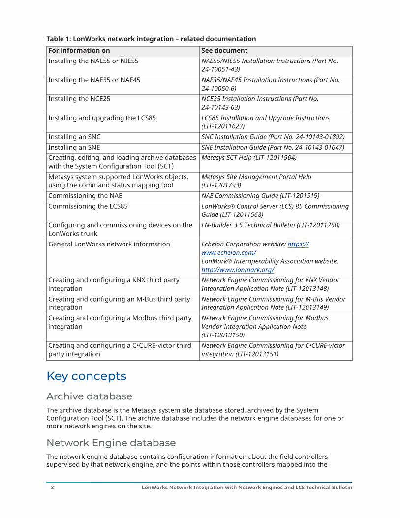
Table 1: LonWorks network integration – related documentationFor information on See documentInstalling the NAE55 or NIE55 NAE55/NIE55 Installation Instructions (Part No.
24-10051-43)Installing the NAE35 or NAE45 NAE35/NAE45 Installation Instructions (Part No.
24-10050-6)Installing the NCE25 NCE25 Installation Instructions (Part No.
24-10143-63)Installing and upgrading the LCS85 LCS85 Installation and Upgrade Instructions
(LIT-12011623)Installing an SNC SNC Installation Guide (Part No. 24-10143-01892)Installing an SNE SNE Installation Guide (Part No. 24-10143-01647)Creating, editing, and loading archive databaseswith the System Configuration Tool (SCT)
Metasys SCT Help (LIT-12011964)
Metasys system supported LonWorks objects,using the command status mapping tool
Metasys Site Management Portal Help(LIT-1201793)
Commissioning the NAE NAE Commissioning Guide (LIT-1201519)Commissioning the LCS85 LonWorks® Control Server (LCS) 85 Commissioning
Guide (LIT-12011568)Configuring and commissioning devices on theLonWorks trunk
LN-Builder 3.5 Technical Bulletin (LIT-12011250)
General LonWorks network information Echelon Corporation website: https://www.echelon.com/LonMark® Interoperability Association website:http://www.lonmark.org/
Creating and configuring a KNX third partyintegration
Network Engine Commissioning for KNX VendorIntegration Application Note (LIT-12013148)
Creating and configuring an M-Bus third partyintegration
Network Engine Commissioning for M-Bus VendorIntegration Application Note (LIT-12013149)
Creating and configuring a Modbus third partyintegration
Network Engine Commissioning for ModbusVendor Integration Application Note(LIT-12013150)
Creating and configuring a C•CURE-victor thirdparty integration
Network Engine Commissioning for C•CURE-victorintegration (LIT-12013151)
Key concepts
Archive databaseThe archive database is the Metasys system site database stored, archived by the SystemConfiguration Tool (SCT). The archive database includes the network engine databases for one ormore network engines on the site.
Network Engine databaseThe network engine database contains configuration information about the field controllerssupervised by that network engine, and the points within those controllers mapped into the
LonWorks Network Integration with Network Engines and LCS Technical Bulletin8
Metasys system. The network engine database resides in flash memory for the NAE and hard diskfor the LCS. Any online changes to the database are not automatically saved to the flash memoryor hard disk; you must perform an Archive command to save your changes. The SCT uploads andarchives the NAE or LCS database from the flash memory to hard disk or other long-term storagemedia. The uploaded database or a database created offline in the SCT can also be downloadedfrom the SCT.
Network Engine database generationTo generate a network engine database of LonWorks enabled field devices, you must first set upa site database, define the network engine, and then populate the network engine with LonWorksenabled field devices and point objects. You can do this online by accessing the network engine inthe Site Management Portal (SMP) UI from a separate computer or offline with the SCT; then thedatabase can be downloaded later to the network engine.
Note: We strongly advise that you do not browse to the SMP UI from a computer runninga server-class operating system (OS). By default, Windows® Internet Explorer® EnhancedSecurity Configuration is enabled on server-class operating systems, and may prevent the SMPUI from launching or loading properly. Access the SMP UI from a computer that is not runninga server-class OS.
In online generation mode, the network engine database can be created using the Auto Discoveryfeature for LonWorks enabled devices and points within a network that are already configured andin operation. For other options, see the LonWorks network integration section.
Network configuration and device limitsConfiguration and commissioning of the LonWorks trunk is performed using the LonWorks networkconfiguration tool LN Builder. You may also use a third-party LonWorks network configuration tool,such as the Echelon® LonMaker® tool to configure and commission the LonWorks trunk. See theLonWorks network integration section.
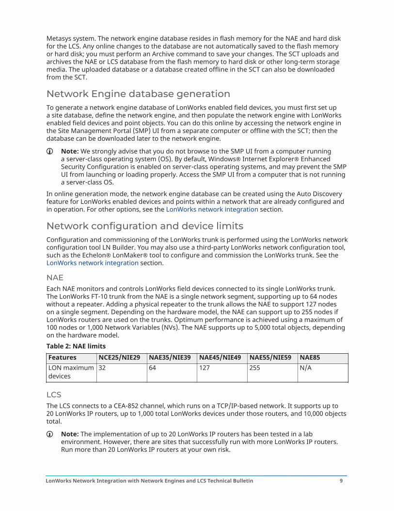
NAEEach NAE monitors and controls LonWorks field devices connected to its single LonWorks trunk.The LonWorks FT-10 trunk from the NAE is a single network segment, supporting up to 64 nodeswithout a repeater. Adding a physical repeater to the trunk allows the NAE to support 127 nodeson a single segment. Depending on the hardware model, the NAE can support up to 255 nodes ifLonWorks routers are used on the trunks. Optimum performance is achieved using a maximum of100 nodes or 1,000 Network Variables (NVs). The NAE supports up to 5,000 total objects, dependingon the hardware model.Table 2: NAE limitsFeatures NCE25/NIE29 NAE35/NIE39 NAE45/NIE49 NAE55/NIE59 NAE85LON maximumdevices
32 64 127 255 N/A
LCSThe LCS connects to a CEA-852 channel, which runs on a TCP/IP-based network. It supports up to20 LonWorks IP routers, up to 1,000 total LonWorks devices under those routers, and 10,000 objectstotal.
Note: The implementation of up to 20 LonWorks IP routers has been tested in a labenvironment. However, there are sites that successfully run with more LonWorks IP routers.Run more than 20 LonWorks IP routers at your own risk.
9LonWorks Network Integration with Network Engines and LCS Technical Bulletin
You can increase the number of objects supported to 25,000 with an LCS license upgrade; however,permanent status item limitations apply after this upgrade. See the LCS permanent status itemlimitation section. Refer to Software Manager Help (LIT-12012389) for information about how tolicense software.
LCS permanent status item limitationWhen you upgrade your LCS to 25,000 objects, Permanent Status Item support is limited to 11,000items. If you exceed the 11,000 Permanent Status Item limitation, point values for PermanentStatus Items no longer continuously update on each polling cycle. See Point object polling. In mostcases, increasing the number of continuously polled items (Permanent Status Items) degradesthe performance to an unacceptable level before reaching the 11,000 Permanent Status Item limit.For example, if your system has 10,000 Permanent Status Items with a 50 point-per-second scanrate, then the total scan time to complete one polling cycle is approximately 200 seconds, assumingoptimal field conditions and router performance.User interaction, such as displaying LonWorks point objects, does not exceed the limit. The majorityof Permanent Status Items stem from extensions and feature objects. For more information onPermanent Status Items, see the Permanent Status item count section.
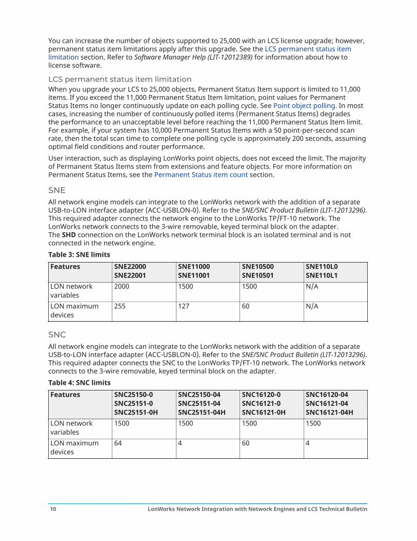
SNEAll network engine models can integrate to the LonWorks network with the addition of a separateUSB-to-LON interface adapter (ACC-USBLON-0). Refer to the SNE/SNC Product Bulletin (LIT-12013296).This required adapter connects the network engine to the LonWorks TP/FT-10 network. TheLonWorks network connects to the 3-wire removable, keyed terminal block on the adapter.The SHD connection on the LonWorks network terminal block is an isolated terminal and is notconnected in the network engine.Table 3: SNE limitsFeatures SNE22000
SNE22001SNE11000SNE11001
SNE10500SNE10501
SNE110L0SNE110L1
LON networkvariables
2000 1500 1500 N/A
LON maximumdevices
255 127 60 N/A
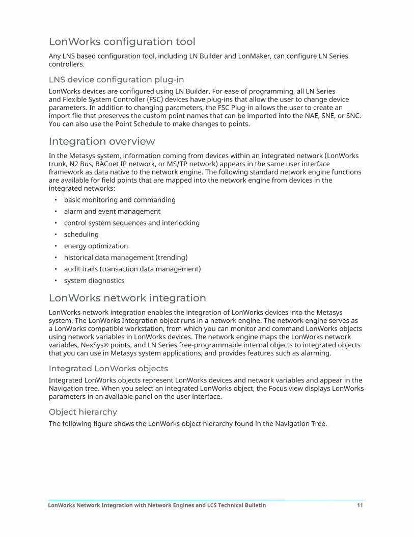
SNCAll network engine models can integrate to the LonWorks network with the addition of a separateUSB-to-LON interface adapter (ACC-USBLON-0). Refer to the SNE/SNC Product Bulletin (LIT-12013296).This required adapter connects the SNC to the LonWorks TP/FT-10 network. The LonWorks networkconnects to the 3-wire removable, keyed terminal block on the adapter.Table 4: SNC limitsFeatures SNC25150-0
SNC25151-0SNC25151-0H
SNC25150-04SNC25151-04SNC25151-04H
SNC16120-0SNC16121-0SNC16121-0H
SNC16120-04SNC16121-04SNC16121-04H
LON networkvariables
1500 1500 1500 1500
LON maximumdevices
64 4 60 4
LonWorks Network Integration with Network Engines and LCS Technical Bulletin10
LonWorks configuration toolAny LNS based configuration tool, including LN Builder and LonMaker, can configure LN Seriescontrollers.
LNS device configuration plug-inLonWorks devices are configured using LN Builder. For ease of programming, all LN Seriesand Flexible System Controller (FSC) devices have plug-ins that allow the user to change deviceparameters. In addition to changing parameters, the FSC Plug-in allows the user to create animport file that preserves the custom point names that can be imported into the NAE, SNE, or SNC.You can also use the Point Schedule to make changes to points.
Integration overviewIn the Metasys system, information coming from devices within an integrated network (LonWorkstrunk, N2 Bus, BACnet IP network, or MS/TP network) appears in the same user interfaceframework as data native to the network engine. The following standard network engine functionsare available for field points that are mapped into the network engine from devices in theintegrated networks:
• basic monitoring and commanding• alarm and event management• control system sequences and interlocking• scheduling• energy optimization• historical data management (trending)• audit trails (transaction data management)• system diagnostics
LonWorks network integrationLonWorks network integration enables the integration of LonWorks devices into the Metasyssystem. The LonWorks Integration object runs in a network engine. The network engine serves asa LonWorks compatible workstation, from which you can monitor and command LonWorks objectsusing network variables in LonWorks devices. The network engine maps the LonWorks networkvariables, NexSys® points, and LN Series free-programmable internal objects to integrated objectsthat you can use in Metasys system applications, and provides features such as alarming.
Integrated LonWorks objectsIntegrated LonWorks objects represent LonWorks devices and network variables and appear in theNavigation tree. When you select an integrated LonWorks object, the Focus view displays LonWorksparameters in an available panel on the user interface.
Object hierarchyThe following figure shows the LonWorks object hierarchy found in the Navigation Tree.
11LonWorks Network Integration with Network Engines and LCS Technical Bulletin
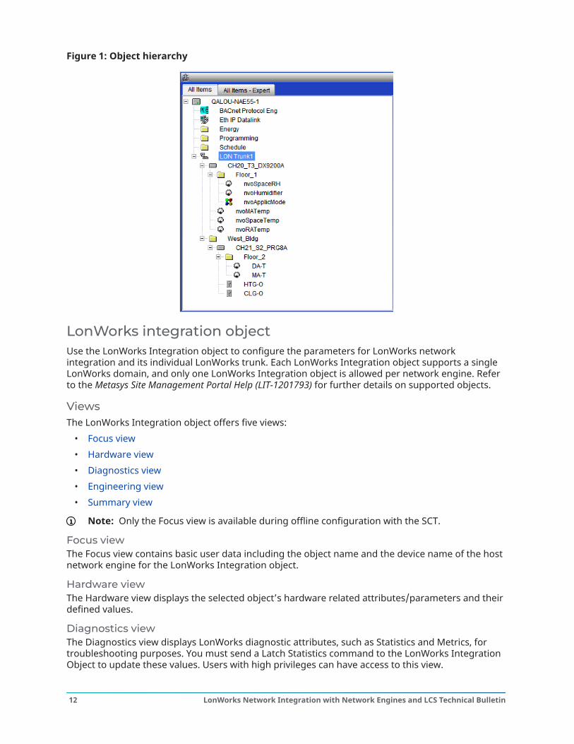
Figure 1: Object hierarchy
LonWorks integration objectUse the LonWorks Integration object to configure the parameters for LonWorks networkintegration and its individual LonWorks trunk. Each LonWorks Integration object supports a singleLonWorks domain, and only one LonWorks Integration object is allowed per network engine. Referto the Metasys Site Management Portal Help (LIT-1201793) for further details on supported objects.
ViewsThe LonWorks Integration object offers five views:
• Focus view• Hardware view• Diagnostics view• Engineering view• Summary view
Note: Only the Focus view is available during offline configuration with the SCT.
Focus viewThe Focus view contains basic user data including the object name and the device name of the hostnetwork engine for the LonWorks Integration object.
Hardware viewThe Hardware view displays the selected object’s hardware related attributes/parameters and theirdefined values.
Diagnostics viewThe Diagnostics view displays LonWorks diagnostic attributes, such as Statistics and Metrics, fortroubleshooting purposes. You must send a Latch Statistics command to the LonWorks IntegrationObject to update these values. Users with high privileges can have access to this view.
LonWorks Network Integration with Network Engines and LCS Technical Bulletin12
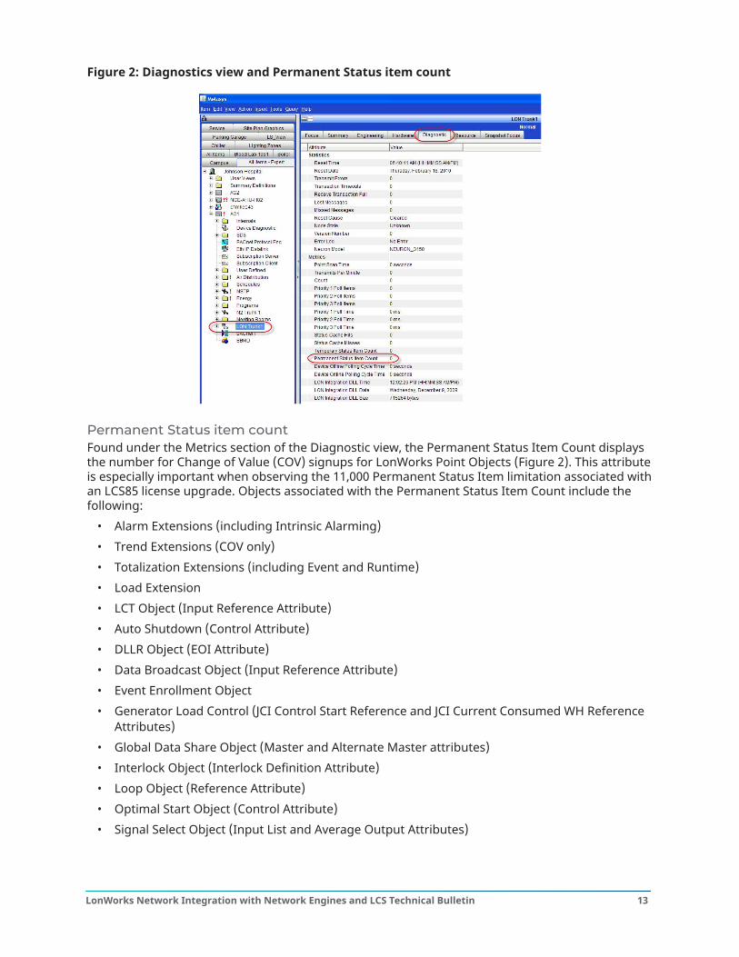
Figure 2: Diagnostics view and Permanent Status item count
Permanent Status item countFound under the Metrics section of the Diagnostic view, the Permanent Status Item Count displaysthe number for Change of Value (COV) signups for LonWorks Point Objects (Figure 2). This attributeis especially important when observing the 11,000 Permanent Status Item limitation associated withan LCS85 license upgrade. Objects associated with the Permanent Status Item Count include thefollowing:
• Alarm Extensions (including Intrinsic Alarming)• Trend Extensions (COV only)• Totalization Extensions (including Event and Runtime)• Load Extension• LCT Object (Input Reference Attribute)• Auto Shutdown (Control Attribute)• DLLR Object (EOI Attribute)• Data Broadcast Object (Input Reference Attribute)• Event Enrollment Object• Generator Load Control (JCI Control Start Reference and JCI Current Consumed WH Reference
Attributes)• Global Data Share Object (Master and Alternate Master attributes)• Interlock Object (Interlock Definition Attribute)• Loop Object (Reference Attribute)• Optimal Start Object (Control Attribute)• Signal Select Object (Input List and Average Output Attributes)
13LonWorks Network Integration with Network Engines and LCS Technical Bulletin

When active, the following panels place the objects in the Temporary Status Item list and then movethe objects immediately to the Permanent Status Item list until the panel is closed. Once you closethe panel, the object moves back to the Temporary Status Item list if the Temporary Status ItemExpiration Time has not expired. If the Temporary Status Item Expiration Time has expired, theobject is removed from the Permanent Status Item list.
• Graphic Object (each instance of a LonWorks Point Object when the graphic is active)• Global Search Query• Group Object (only when the Group Object is active)• Point Summary Display Panel• Device Point Summary Display Panel• User View
Engineering viewThe Engineering view allows you to view data in LonWorks devices that are connected to thenetwork engine or LCS LonWorks trunk. This view is typically used by advanced users with theappropriate access authority to directly view and change data in LonWorks devices. LN Series free-programmable internal points cannot be viewed or modified. The devices and network variablesmay or may not be integrated (mapped) to network engine objects in the Navigation Tree. Routersare shown in this view, but cannot be mapped as devices. Any devices or network variables that aremapped to network engine objects are displayed in a Mapped Devices folder.The Engineering view contains the Integration Tree and Integration view panels. The IntegrationTree panel contains a list of known LonWorks devices connected to the network engine along withtheir network variables. The Integration view panel displays the details about the LonWorks deviceor network variable selected in the Integration Tree.
Note: You must issue a device discovery command to view any routers in the Engineeringview.
After you create a LonWorks Integration object, the Integration Tree is empty until you addLonWorks enabled devices, either manually or by using Auto Discovery. See Detailed Procedures forinstructions on adding LonWorks devices.The Engineering view Integration Tree is the only place you can view routers, as they are not shownin the Navigation Tree. Detailed information about each router is available in the Summary view.
Mapped Devices folderA Mapped Devices folder is located under the LonWorks Integration object in the Engineeringview. This folder only contains mapped devices and does not show routers because they cannot bemapped.
Summary viewIn the Integration view section, you can use the Summary view to display a list of devices and thevalues of their network variables, or the Detail view to see the parameters of a selected item. Thecontent in the Summary view is dependent on the device selected in the Integration Tree.
Resource filesThe LonWorks network integration requires resource files to support integrating LonWorks enableddevices. Device resource files have file extensions of .XIF (External Interface File), .TYP (TypeFile), and .FPT (Functional Profile Template), and provide device type and configuration data.For example, an LN-VAVLF-1 controller has the following three device specific resource files: LN-VAVLF-1 110.XIF, LNVAVL1.TYP, and LNVAVL1.FTP.
Note: .TYP and .FPT resource files may not be provided. In this case, only the .XIF file isneeded.
LonWorks Network Integration with Network Engines and LCS Technical Bulletin14
Network EngineIn addition to the device specific resource files, the LonWorks Integration object requires theSTANDARD.TYP and STANDARD.FPT resource files, and a NVConfig.dat file. This NVConfig.datfile is created automatically, but you need to update it with the correct configuration data using anetwork configuration tool, such as LN Builder. See Defining a network engine on the LonWorkstrunk.
Note: Once you have created and updated the LonWorks Integration object, add all theresource files for the LonWorks enabled device types you intend to add to the LonWorks trunk.Adding, importing device data, or mapping a LonWorks enabled device before loading theresource files can produce undesired results that may require a reboot.
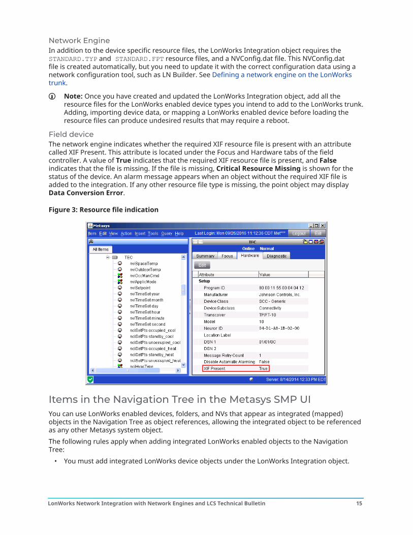
Field deviceThe network engine indicates whether the required XIF resource file is present with an attributecalled XIF Present. This attribute is located under the Focus and Hardware tabs of the fieldcontroller. A value of True indicates that the required XIF resource file is present, and Falseindicates that the file is missing. If the file is missing, Critical Resource Missing is shown for thestatus of the device. An alarm message appears when an object without the required XIF file isadded to the integration. If any other resource file type is missing, the point object may displayData Conversion Error.
Figure 3: Resource file indication
Items in the Navigation Tree in the Metasys SMP UIYou can use LonWorks enabled devices, folders, and NVs that appear as integrated (mapped)objects in the Navigation Tree as object references, allowing the integrated object to be referencedas any other Metasys system object.The following rules apply when adding integrated LonWorks enabled objects to the NavigationTree:
• You must add integrated LonWorks device objects under the LonWorks Integration object.
15LonWorks Network Integration with Network Engines and LCS Technical Bulletin
Note: You may add devices under a folder as long as the folder resides under theLonWorks Integration object.
• You must add LonWorks point objects under a LonWorks device object.• To group LonWorks point objects within a LonWorks device, add folder (container) objects
under the LonWorks device object and add the LonWorks point objects under a folder object.
Note: See the Object hierarchy section for an illustration of objects in the NavigationTree.
LonWorks device objectLonWorks Device Objects are a representation of a single LonWorks Field device. Each field device,identified through the DSN address, can be mapped only once.
Device naming conventions during Auto DiscoveryDevice names for auto-discovered devices consist of the device type (extracted from the device'sProgram ID) and its DNS address, providing a unique identifier for each device (for example, PlantController 42 0D 04). The DSN number is used as a unique identifier for each device. Since the DSNnumber is not a required part of the name, it can be removed if necessary.
LonWorks Point ObjectsLonWorks Point Objects represent point data from a particular LonWorks Device Object. The datais represented as an analog input (AI), analog output (AO), binary input (BI), binary output (BO),multiple input (MI), and multiple output (MO). Generic integration objects (GIOs) can be added viaimport file only.
Mapping of field valuesEach LonWorks Point Object can be mapped from an LN Series Internal, Network Variable, orNexSys Point object. In the case of Network Variable or NexSys Point, the mapping can be of thewhole or a portion of the entity.
LonWorks Field Point object supportThe Metasys system supports network variables of all LonMark SVNTs, all point types in NexSyscontrollers, and all LN Series Free Programmable Controller internal point types.
Mapping internal points of LN Series controllersYou can map the internal points of LN Series Free Programmable Controllers. Once you exposethese points, you can monitor and control them from the network engine. The points includeinternal variables, constants, inputs, outputs, controllers, timers, and optimal start objects. Keep inmind that each mapped object contributes to the maximum object count allowed for the networkengine. Table 5 shows a list of available mapping points.
Note: The target reference is the type and number of the mapped field point or networkvariable, which must correspond to the point or NV index in the host LonWorks enabled device.When defining the object, replace the x by the index of the object being referenced. For validnetwork engine object types, AI stands for analog input, AO stands for analog output, BIstands for binary input, BO stands for binary output, MI stands for multiple input, and MOstands for multiple output.
LonWorks Network Integration with Network Engines and LCS Technical Bulletin16
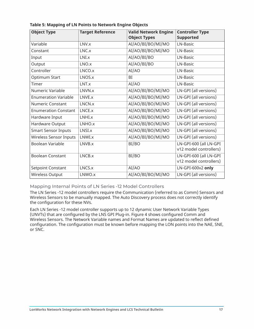
Table 5: Mapping of LN Points to Network Engine ObjectsObject Type Target Reference Valid Network Engine
Object TypesController TypeSupported
Variable LNV.x AI/AO/BI/BO/MI/MO LN-BasicConstant LNC.x AI/AO/BI/BO/MI/MO LN-BasicInput LNI.x AI/AO/BI/BO LN-BasicOutput LNO.x AI/AO/BI/BO LN-BasicController LNCO.x AI/AO LN-BasicOptimum Start LNOS.x BI LN-BasicTimer LNT.x AI/AO LN-BasicNumeric Variable LNVN.x AI/AO/BI/BO/MI/MO LN-GPI (all versions)Enumeration Variable LNVE.x AI/AO/BI/BO/MI/MO LN-GPI (all versions)Numeric Constant LNCN.x AI/AO/BI/BO/MI/MO LN-GPI (all versions)Enumeration Constant LNCE.x AI/AO/BI/BO/MI/MO LN-GPI (all versions)Hardware Input LNHI.x AI/AO/BI/BO/MI/MO LN-GPI (all versions)Hardware Output LNHO.x AI/AO/BI/BO/MI/MO LN-GPI (all versions)Smart Sensor Inputs LNSI.x AI/AO/BI/BO/MI/MO LN-GPI (all versions)Wireless Sensor Inputs LNWI.x AI/AO/BI/BO/MI/MO LN-GPI (all versions)Boolean Variable LNVB.x BI/BO LN-GPI-600 (all LN-GPI
v12 model controllers)Boolean Constant LNCB.x BI/BO LN-GPI-600 (all LN-GPI
v12 model controllers)Setpoint Constant LNCS.x AI/AO LN-GPI-600v2 onlyWireless Output LNWO.x AI/AO/BI/BO/MI/MO LN-GPI (all versions)
Mapping Internal Points of LN Series -12 Model ControllersThe LN Series -12 model controllers require the Communication (referred to as Comm) Sensors andWireless Sensors to be manually mapped. The Auto Discovery process does not correctly identifythe configuration for these NVs.Each LN Series -12 model controller supports up to 12 dynamic User Network Variable Types(UNVTs) that are configured by the LNS GPI Plug-in. Figure 4 shows configured Comm andWireless Sensors. The Network Variable names and Format Names are updated to reflect definedconfiguration. The configuration must be known before mapping the LON points into the NAE, SNE,or SNC.
17LonWorks Network Integration with Network Engines and LCS Technical Bulletin
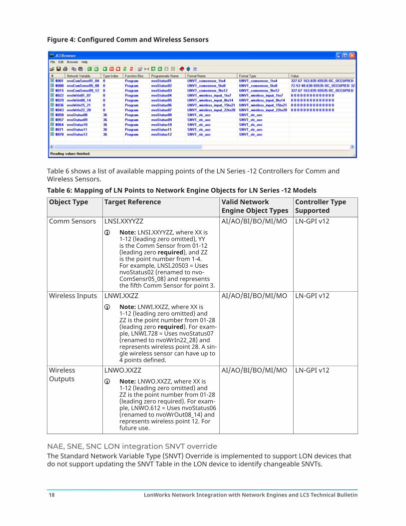
Figure 4: Configured Comm and Wireless Sensors
Table 6 shows a list of available mapping points of the LN Series -12 Controllers for Comm andWireless Sensors.Table 6: Mapping of LN Points to Network Engine Objects for LN Series -12 ModelsObject Type Target Reference Valid Network
Engine Object TypesController TypeSupported
Comm Sensors LNSI.XXYYZZNote: LNSI.XXYYZZ, where XX is1-12 (leading zero omitted), YYis the Comm Sensor from 01-12(leading zero required), and ZZis the point number from 1-4.For example, LNSI.20503 = UsesnvoStatus02 (renamed to nvo-ComSensr05_08) and representsthe fifth Comm Sensor for point 3.
AI/AO/BI/BO/MI/MO LN-GPI v12
Wireless Inputs LNWI.XXZZNote: LNWI.XXZZ, where XX is1-12 (leading zero omitted) andZZ is the point number from 01-28(leading zero required). For exam-ple, LNWI.728 = Uses nvoStatus07(renamed to nvoWrIn22_28) andrepresents wireless point 28. A sin-gle wireless sensor can have up to4 points defined.
AI/AO/BI/BO/MI/MO LN-GPI v12
WirelessOutputs
LNWO.XXZZNote: LNWO.XXZZ, where XX is1-12 (leading zero omitted) andZZ is the point number from 01-28(leading zero required). For exam-ple, LNWO.612 = Uses nvoStatus06(renamed to nvoWrOut08_14) andrepresents wireless point 12. Forfuture use.
AI/AO/BI/BO/MI/MO LN-GPI v12
NAE, SNE, SNC LON integration SNVT overrideThe Standard Network Variable Type (SNVT) Override is implemented to support LON devices thatdo not support updating the SNVT Table in the LON device to identify changeable SNVTs.
LonWorks Network Integration with Network Engines and LCS Technical Bulletin18
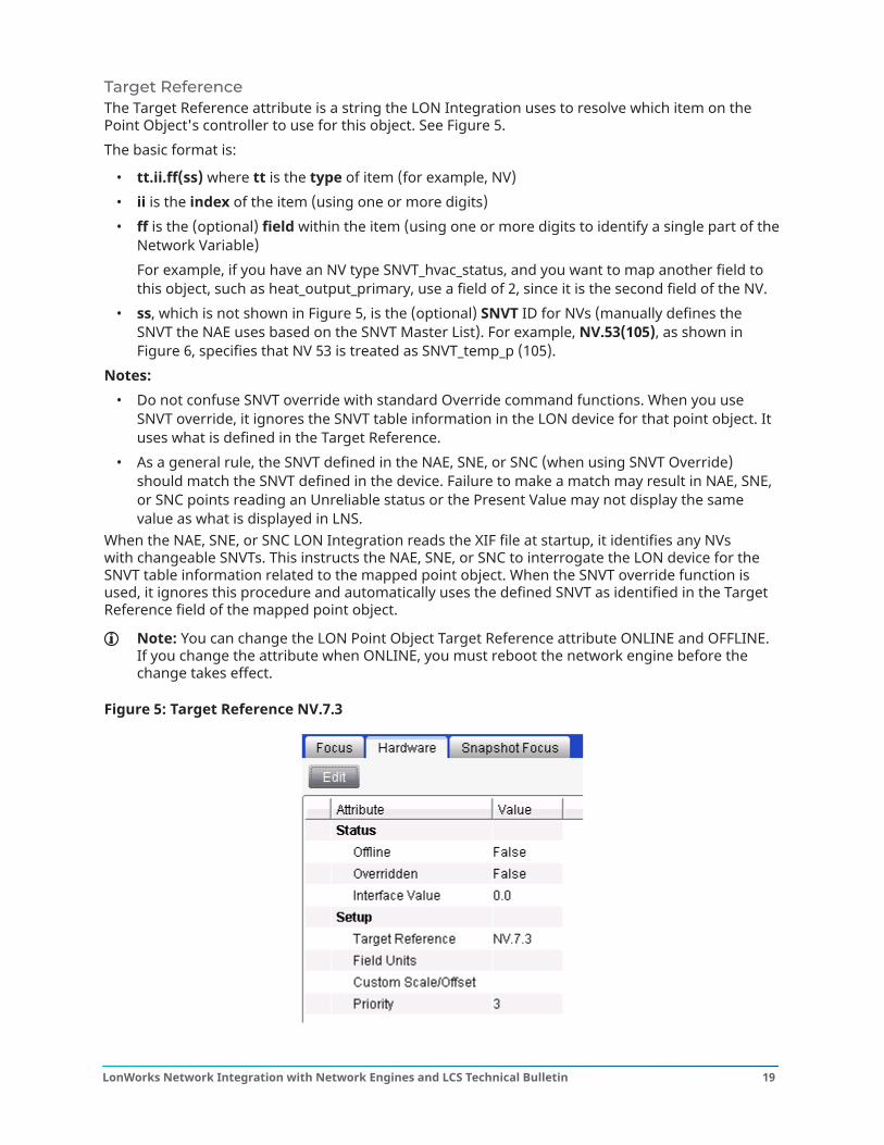
Target ReferenceThe Target Reference attribute is a string the LON Integration uses to resolve which item on thePoint Object's controller to use for this object. See Figure 5.The basic format is:
• tt.ii.ff(ss) where tt is the type of item (for example, NV)• ii is the index of the item (using one or more digits)• ff is the (optional) field within the item (using one or more digits to identify a single part of the
Network Variable)For example, if you have an NV type SNVT_hvac_status, and you want to map another field tothis object, such as heat_output_primary, use a field of 2, since it is the second field of the NV.
• ss, which is not shown in Figure 5, is the (optional) SNVT ID for NVs (manually defines theSNVT the NAE uses based on the SNVT Master List). For example, NV.53(105), as shown inFigure 6, specifies that NV 53 is treated as SNVT_temp_p (105).
Notes:• Do not confuse SNVT override with standard Override command functions. When you use
SNVT override, it ignores the SNVT table information in the LON device for that point object. Ituses what is defined in the Target Reference.
• As a general rule, the SNVT defined in the NAE, SNE, or SNC (when using SNVT Override)should match the SNVT defined in the device. Failure to make a match may result in NAE, SNE,or SNC points reading an Unreliable status or the Present Value may not display the samevalue as what is displayed in LNS.
When the NAE, SNE, or SNC LON Integration reads the XIF file at startup, it identifies any NVswith changeable SNVTs. This instructs the NAE, SNE, or SNC to interrogate the LON device for theSNVT table information related to the mapped point object. When the SNVT override function isused, it ignores this procedure and automatically uses the defined SNVT as identified in the TargetReference field of the mapped point object.
Note: You can change the LON Point Object Target Reference attribute ONLINE and OFFLINE.If you change the attribute when ONLINE, you must reboot the network engine before thechange takes effect.
Figure 5: Target Reference NV.7.3
19LonWorks Network Integration with Network Engines and LCS Technical Bulletin
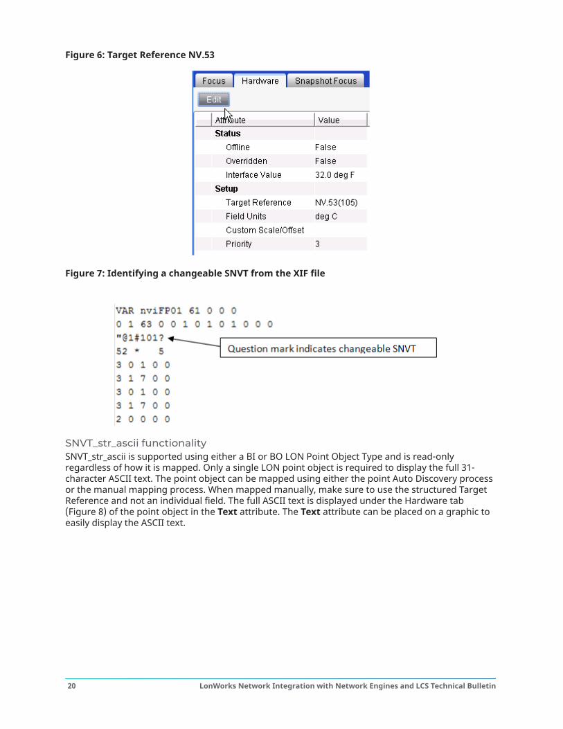
Figure 6: Target Reference NV.53
Figure 7: Identifying a changeable SNVT from the XIF file
SNVT_str_ascii functionalitySNVT_str_ascii is supported using either a BI or BO LON Point Object Type and is read-onlyregardless of how it is mapped. Only a single LON point object is required to display the full 31-character ASCII text. The point object can be mapped using either the point Auto Discovery processor the manual mapping process. When mapped manually, make sure to use the structured TargetReference and not an individual field. The full ASCII text is displayed under the Hardware tab(Figure 8) of the point object in the Text attribute. The Text attribute can be placed on a graphic toeasily display the ASCII text.
LonWorks Network Integration with Network Engines and LCS Technical Bulletin20
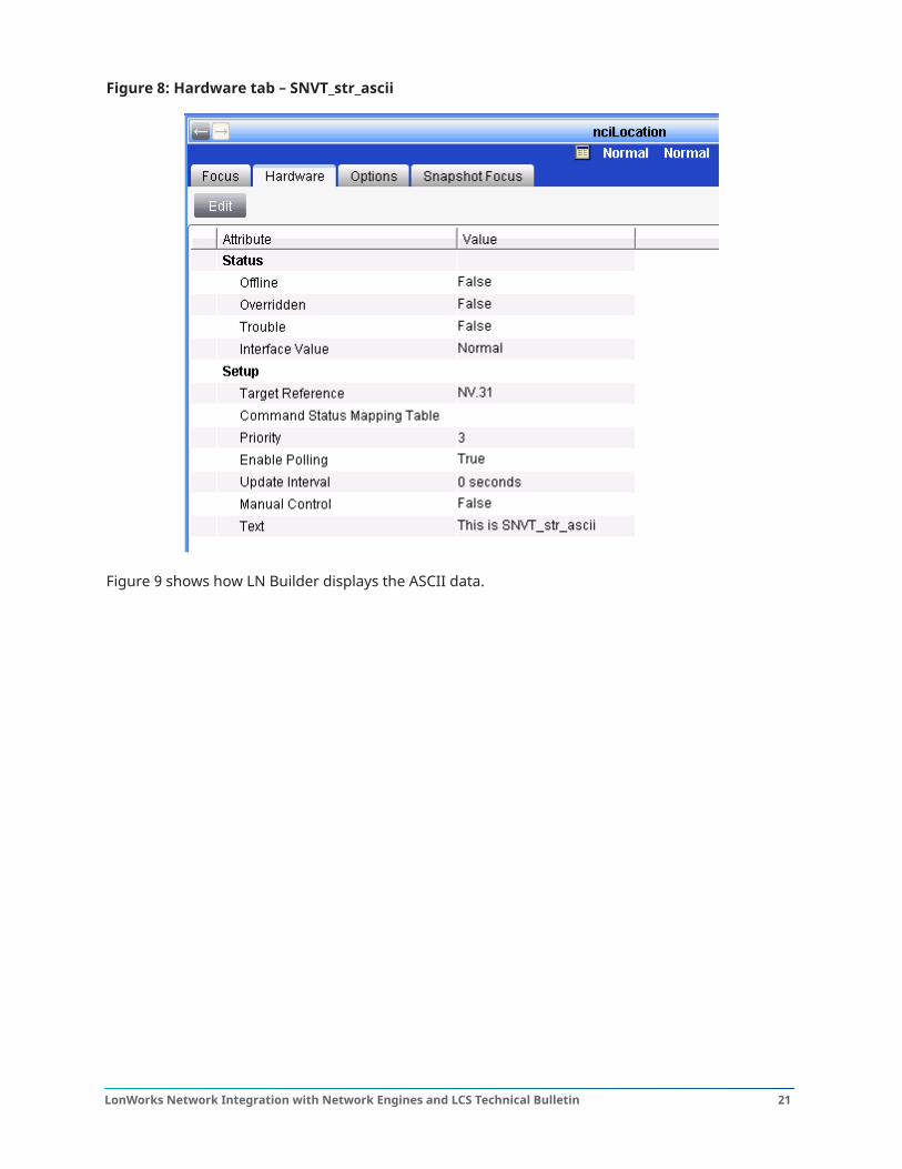
Figure 8: Hardware tab – SNVT_str_ascii
Figure 9 shows how LN Builder displays the ASCII data.
21LonWorks Network Integration with Network Engines and LCS Technical Bulletin
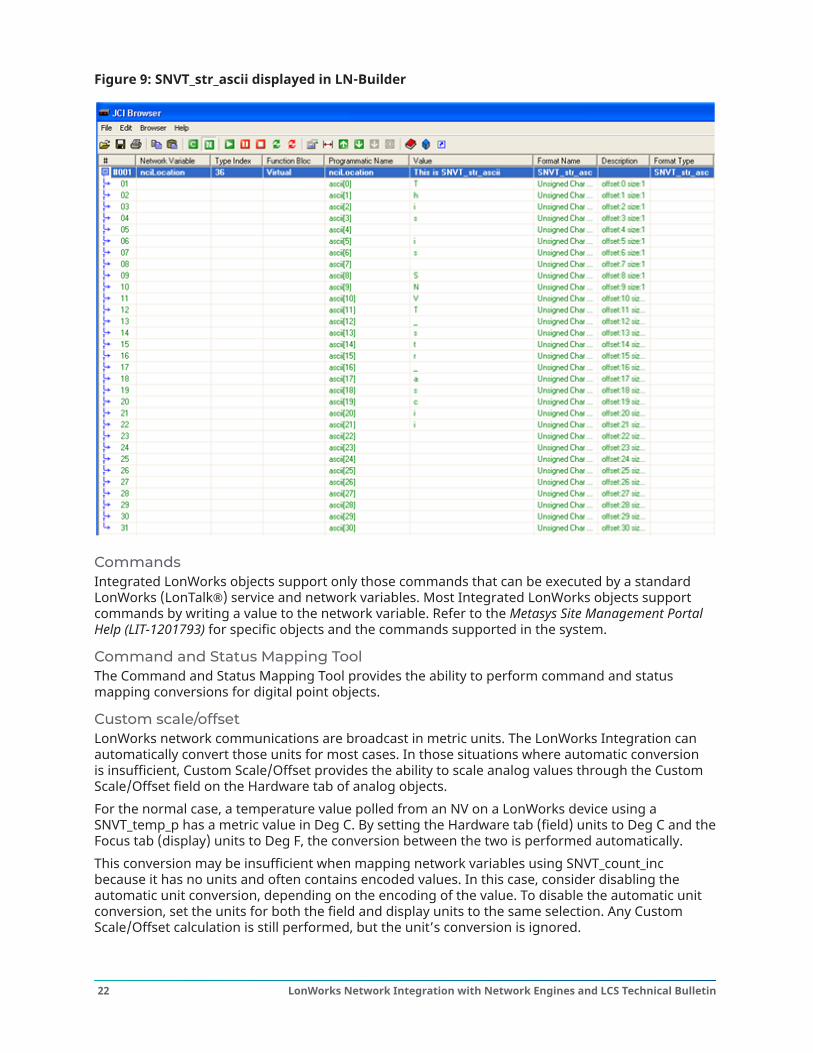
Figure 9: SNVT_str_ascii displayed in LN-Builder
CommandsIntegrated LonWorks objects support only those commands that can be executed by a standardLonWorks (LonTalk®) service and network variables. Most Integrated LonWorks objects supportcommands by writing a value to the network variable. Refer to the Metasys Site Management PortalHelp (LIT-1201793) for specific objects and the commands supported in the system.
Command and Status Mapping ToolThe Command and Status Mapping Tool provides the ability to perform command and statusmapping conversions for digital point objects.
Custom scale/offsetLonWorks network communications are broadcast in metric units. The LonWorks Integration canautomatically convert those units for most cases. In those situations where automatic conversionis insufficient, Custom Scale/Offset provides the ability to scale analog values through the CustomScale/Offset field on the Hardware tab of analog objects.For the normal case, a temperature value polled from an NV on a LonWorks device using aSNVT_temp_p has a metric value in Deg C. By setting the Hardware tab (field) units to Deg C and theFocus tab (display) units to Deg F, the conversion between the two is performed automatically.This conversion may be insufficient when mapping network variables using SNVT_count_incbecause it has no units and often contains encoded values. In this case, consider disabling theautomatic unit conversion, depending on the encoding of the value. To disable the automatic unitconversion, set the units for both the field and display units to the same selection. Any CustomScale/Offset calculation is still performed, but the unit’s conversion is ignored.
LonWorks Network Integration with Network Engines and LCS Technical Bulletin22
For example, to add a multiplier of 0.1 to a mapped network variable that normally shows 831 torepresent 83.1 Deg F, add a Custom Scale/Offset formula of x*0.1 and set both the Field Units andthe Units to Deg F.
Note: By default, the math performed by the Custom Scale/Offset is applied after the unitconversion. To apply the conversion first, place a B in the field before the formula.
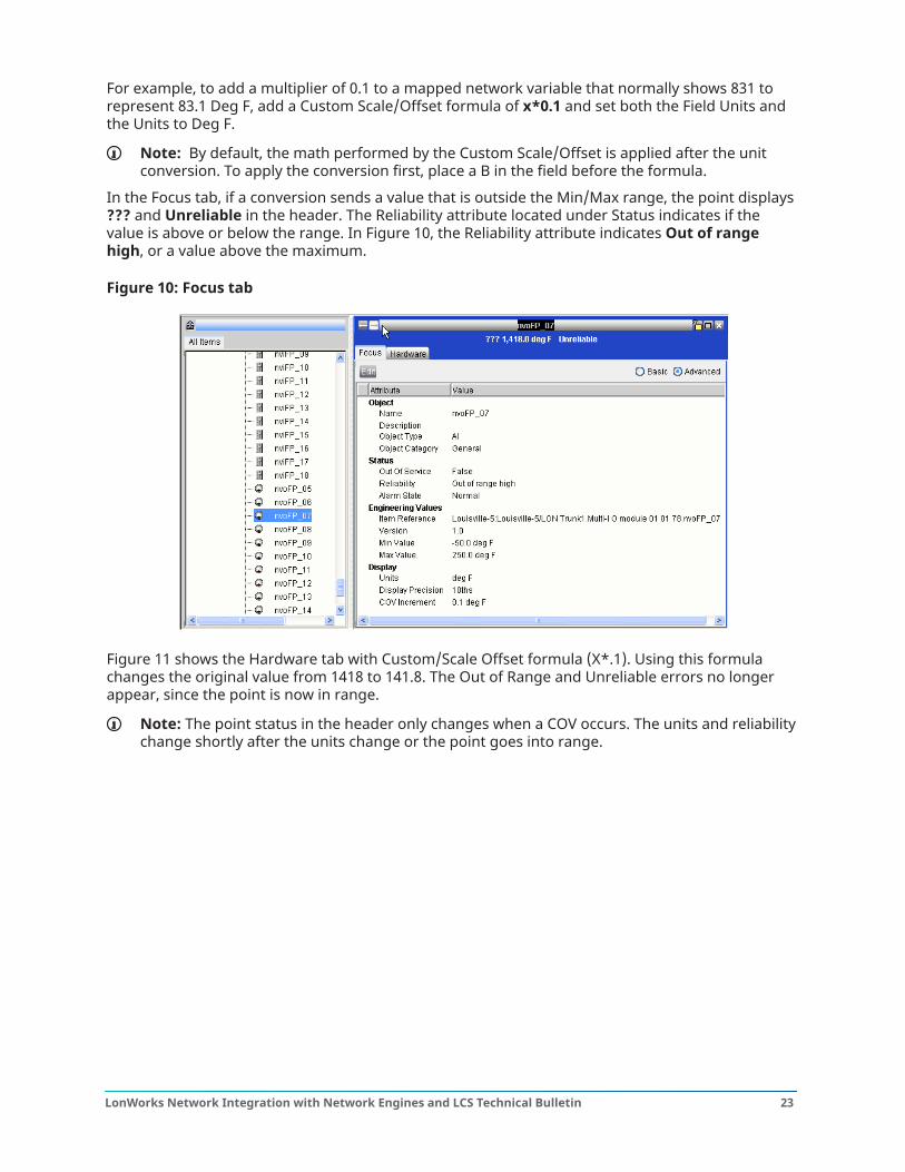
In the Focus tab, if a conversion sends a value that is outside the Min/Max range, the point displays??? and Unreliable in the header. The Reliability attribute located under Status indicates if thevalue is above or below the range. In Figure 10, the Reliability attribute indicates Out of rangehigh, or a value above the maximum.
Figure 10: Focus tab
Figure 11 shows the Hardware tab with Custom/Scale Offset formula (X*.1). Using this formulachanges the original value from 1418 to 141.8. The Out of Range and Unreliable errors no longerappear, since the point is now in range.
Note: The point status in the header only changes when a COV occurs. The units and reliabilitychange shortly after the units change or the point goes into range.
23LonWorks Network Integration with Network Engines and LCS Technical Bulletin
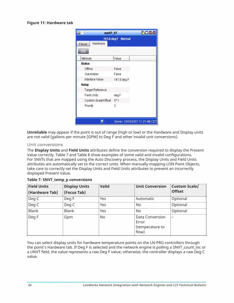
Figure 11: Hardware tab
Unreliable may appear if the point is out of range (high or low) or the Hardware and Display unitsare not valid (gallons per minute [GPM] to Deg F and other invalid unit conversions).
Unit conversionsThe Display Units and Field Units attributes define the conversion required to display the PresentValue correctly. Table 7 and Table 8 show examples of some valid and invalid configurations.For SNVTs that are mapped using the Auto Discovery process, the Display Units and Field Unitsattributes are automatically set to the correct units. When manually mapping LON Point Objects,take care to correctly set the Display Units and Field Units attributes to prevent an incorrectlydisplayed Present Value.Table 7: SNVT_temp_p conversionsField Units(Hardware Tab)
Display Units(Focus Tab)
Valid Unit Conversion Custom Scale/Offset
Deg C Deg F Yes Automatic OptionalDeg C Deg C Yes No OptionalBlank Blank Yes No OptionalDeg F Gpm No Data Conversion
Error(temperature toflow)
–
You can select display units for hardware temperature points on the LN-PRG controllers throughthe point’s Hardware tab. If Deg F is selected and the network engine is polling a SNVT_count_inc ora UNVT field, the value represents a raw Deg F value; otherwise, the controller displays a raw Deg Cvalue.
LonWorks Network Integration with Network Engines and LCS Technical Bulletin24
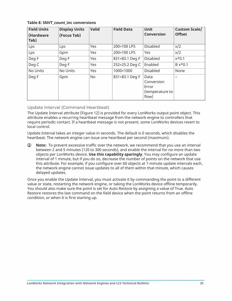
Table 8: SNVT_count_inc conversionsField Units(HardwareTab)
Display Units(Focus Tab)
Valid Field Data UnitConversion
Custom Scale/Offset
Lps Lps Yes 200=100 LPS Disabled x/2Lps Gpm Yes 200=100 LPS Yes x/2Deg F Deg F Yes 831=83.1 Deg F Disabled x*0.1Deg C Deg F Yes 252=25.2 Deg C Enabled B x*0.1No Units No Units Yes 1000=1000 Disabled NoneDeg F Gpm No 831=83.1 Deg F Data
ConversionError(temperature toflow)
–
Update Interval (Command Heartbeat)The Update Interval attribute (Figure 12) is provided for every LonWorks output point object. Thisattribute enables a recurring heartbeat message from the network engine to controllers thatrequire periodic contact. If a heartbeat message is not present, some LonWorks devices revert tolocal control.Update Interval takes an integer value in seconds. The default is 0 seconds, which disables theheartbeat. The network engine can issue one heartbeat per second (maximum).
Note: To prevent excessive traffic over the network, we recommend that you use an intervalbetween 2 and 5 minutes (120 to 300 seconds), and enable the interval for no more than twoobjects per LonWorks device. Use this capability sparingly. You may configure an updateinterval of 1 minute, but if you do so, decrease the number of points on the network that usethis attribute. For example, if you configure over 60 objects at 1-minute update intervals each,the network engine cannot issue updates to all of them within that minute, which causesdelayed updates.
Once you enable the Update Interval, you must activate it by commanding the point to a differentvalue or state, restarting the network engine, or taking the LonWorks device offline temporarily.You should also make sure the point is set for Auto Restore by assigning a value of True. AutoRestore restores the last command on the field device when the point returns from an offlinecondition, or when it is first starting up.
25LonWorks Network Integration with Network Engines and LCS Technical Bulletin
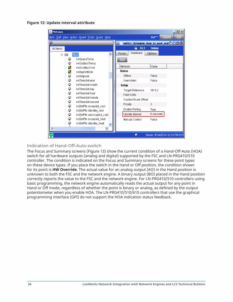
Figure 12: Update interval attribute
Indication of Hand-Off-Auto switchThe Focus and Summary screens (Figure 13) show the current condition of a Hand-Off-Auto (HOA)switch for all hardware outputs (analog and digital) supported by the FSC and LN-PRG410/510controller. The condition is indicated on the Focus and Summary screens for these point typeson these device types. If you place the switch in the Hand or Off position, the condition shownfor its point is HW Override. The actual value for an analog output (AO) in the Hand position isunknown to both the FSC and the network engine. A binary output (BO) placed in the Hand positioncorrectly reports the value to the FSC and the network engine. For LN-PRG410/510 controllers usingbasic programming, the network engine automatically reads the actual output for any point inHand or Off mode, regardless of whether the point is binary or analog, as defined by the outputpotentiometer when you enable HOA. The LN-PRG410/510/610 controllers that use the graphicalprogramming interface (GPI) do not support the HOA indication status feedback.
LonWorks Network Integration with Network Engines and LCS Technical Bulletin26
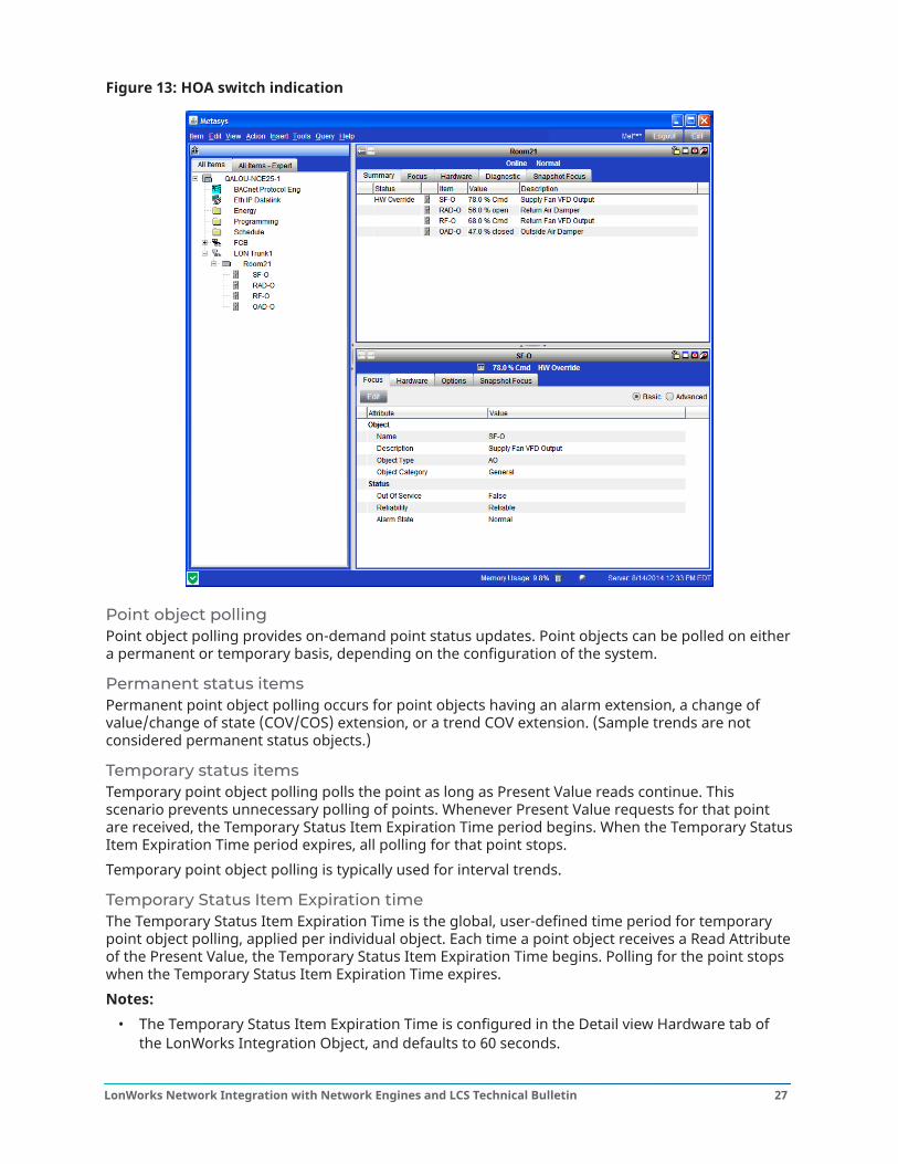
Figure 13: HOA switch indication
Point object pollingPoint object polling provides on-demand point status updates. Point objects can be polled on eithera permanent or temporary basis, depending on the configuration of the system.
Permanent status itemsPermanent point object polling occurs for point objects having an alarm extension, a change ofvalue/change of state (COV/COS) extension, or a trend COV extension. (Sample trends are notconsidered permanent status objects.)
Temporary status itemsTemporary point object polling polls the point as long as Present Value reads continue. Thisscenario prevents unnecessary polling of points. Whenever Present Value requests for that pointare received, the Temporary Status Item Expiration Time period begins. When the Temporary StatusItem Expiration Time period expires, all polling for that point stops.Temporary point object polling is typically used for interval trends.
Temporary Status Item Expiration timeThe Temporary Status Item Expiration Time is the global, user-defined time period for temporarypoint object polling, applied per individual object. Each time a point object receives a Read Attributeof the Present Value, the Temporary Status Item Expiration Time begins. Polling for the point stopswhen the Temporary Status Item Expiration Time expires.Notes:
• The Temporary Status Item Expiration Time is configured in the Detail view Hardware tab ofthe LonWorks Integration Object, and defaults to 60 seconds.
27LonWorks Network Integration with Network Engines and LCS Technical Bulletin
• Changing the Temporary Status Item Expiration Time to a value greater than the trend intervalresults in nonstop data trending.
Priority levelsAll point objects are assigned a priority level. Priorities are assigned on a point-by-point basis, usinga three-level priority scheme. The most critical points are assigned Priority 1, less critical points areassigned Priority 2, and non-critical points are assigned Priority 3. Priority 3 is the default value forall objects.
Note: The three-level priority scheme is not maintained if the number of point objectsassigned Priority 1 is greater than the number of point objects assigned Priority 2 or Priority 3.
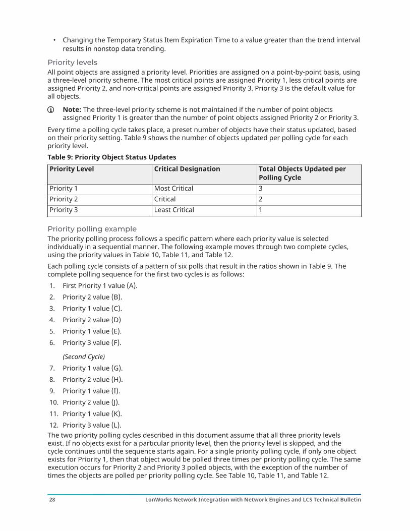
Every time a polling cycle takes place, a preset number of objects have their status updated, basedon their priority setting. Table 9 shows the number of objects updated per polling cycle for eachpriority level.Table 9: Priority Object Status UpdatesPriority Level Critical Designation Total Objects Updated per
Polling CyclePriority 1 Most Critical 3Priority 2 Critical 2Priority 3 Least Critical 1
Priority polling exampleThe priority polling process follows a specific pattern where each priority value is selectedindividually in a sequential manner. The following example moves through two complete cycles,using the priority values in Table 10, Table 11, and Table 12.Each polling cycle consists of a pattern of six polls that result in the ratios shown in Table 9. Thecomplete polling sequence for the first two cycles is as follows:1. First Priority 1 value (A).2. Priority 2 value (B).3. Priority 1 value (C).4. Priority 2 value (D)5. Priority 1 value (E).6. Priority 3 value (F).
(Second Cycle)7. Priority 1 value (G).8. Priority 2 value (H).9. Priority 1 value (I).10. Priority 2 value (J).11. Priority 1 value (K).12. Priority 3 value (L).
The two priority polling cycles described in this document assume that all three priority levelsexist. If no objects exist for a particular priority level, then the priority level is skipped, and thecycle continues until the sequence starts again. For a single priority polling cycle, if only one objectexists for Priority 1, then that object would be polled three times per priority polling cycle. The sameexecution occurs for Priority 2 and Priority 3 polled objects, with the exception of the number oftimes the objects are polled per priority polling cycle. See Table 10, Table 11, and Table 12.
LonWorks Network Integration with Network Engines and LCS Technical Bulletin28
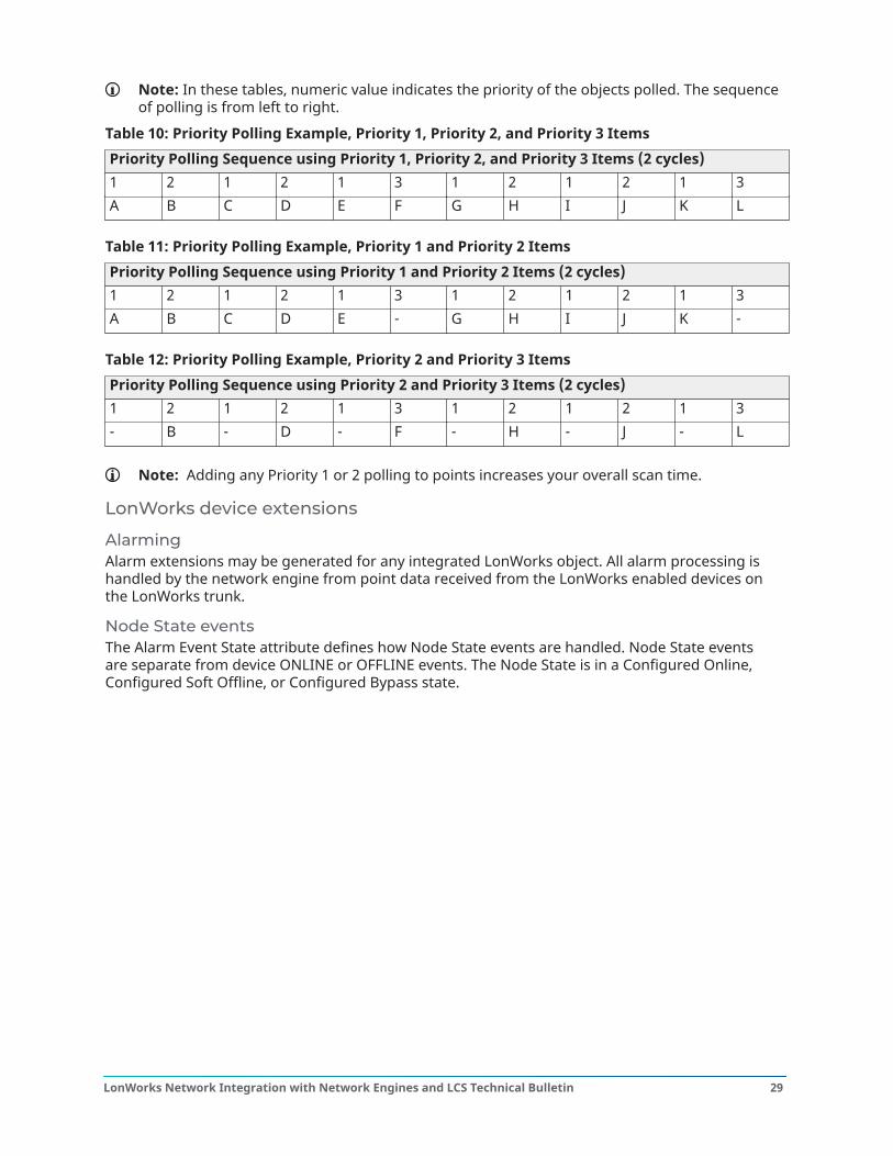
Note: In these tables, numeric value indicates the priority of the objects polled. The sequenceof polling is from left to right.
Table 10: Priority Polling Example, Priority 1, Priority 2, and Priority 3 ItemsPriority Polling Sequence using Priority 1, Priority 2, and Priority 3 Items (2 cycles)1 2 1 2 1 3 1 2 1 2 1 3A B C D E F G H I J K L
Table 11: Priority Polling Example, Priority 1 and Priority 2 ItemsPriority Polling Sequence using Priority 1 and Priority 2 Items (2 cycles)1 2 1 2 1 3 1 2 1 2 1 3A B C D E - G H I J K -
Table 12: Priority Polling Example, Priority 2 and Priority 3 ItemsPriority Polling Sequence using Priority 2 and Priority 3 Items (2 cycles)1 2 1 2 1 3 1 2 1 2 1 3- B - D - F - H - J - L
Note: Adding any Priority 1 or 2 polling to points increases your overall scan time.
LonWorks device extensions
AlarmingAlarm extensions may be generated for any integrated LonWorks object. All alarm processing ishandled by the network engine from point data received from the LonWorks enabled devices onthe LonWorks trunk.
Node State eventsThe Alarm Event State attribute defines how Node State events are handled. Node State eventsare separate from device ONLINE or OFFLINE events. The Node State is in a Configured Online,Configured Soft Offline, or Configured Bypass state.
29LonWorks Network Integration with Network Engines and LCS Technical Bulletin
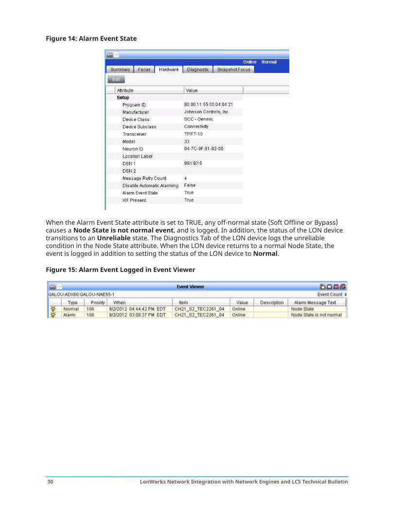
Figure 14: Alarm Event State
When the Alarm Event State attribute is set to TRUE, any off-normal state (Soft Offline or Bypass)causes a Node State is not normal event, and is logged. In addition, the status of the LON devicetransitions to an Unreliable state. The Diagnostics Tab of the LON device logs the unreliablecondition in the Node State attribute. When the LON device returns to a normal Node State, theevent is logged in addition to setting the status of the LON device to Normal.
Figure 15: Alarm Event Logged in Event Viewer
LonWorks Network Integration with Network Engines and LCS Technical Bulletin30
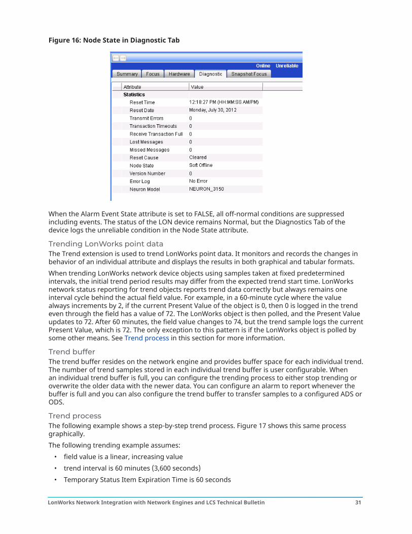
Figure 16: Node State in Diagnostic Tab
When the Alarm Event State attribute is set to FALSE, all off-normal conditions are suppressedincluding events. The status of the LON device remains Normal, but the Diagnostics Tab of thedevice logs the unreliable condition in the Node State attribute.
Trending LonWorks point dataThe Trend extension is used to trend LonWorks point data. It monitors and records the changes inbehavior of an individual attribute and displays the results in both graphical and tabular formats.When trending LonWorks network device objects using samples taken at fixed predeterminedintervals, the initial trend period results may differ from the expected trend start time. LonWorksnetwork status reporting for trend objects reports trend data correctly but always remains oneinterval cycle behind the actual field value. For example, in a 60-minute cycle where the valuealways increments by 2, if the current Present Value of the object is 0, then 0 is logged in the trendeven through the field has a value of 72. The LonWorks object is then polled, and the Present Valueupdates to 72. After 60 minutes, the field value changes to 74, but the trend sample logs the currentPresent Value, which is 72. The only exception to this pattern is if the LonWorks object is polled bysome other means. See Trend process in this section for more information.
Trend bufferThe trend buffer resides on the network engine and provides buffer space for each individual trend.The number of trend samples stored in each individual trend buffer is user configurable. Whenan individual trend buffer is full, you can configure the trending process to either stop trending oroverwrite the older data with the newer data. You can configure an alarm to report whenever thebuffer is full and you can also configure the trend buffer to transfer samples to a configured ADS orODS.
Trend processThe following example shows a step-by-step trend process. Figure 17 shows this same processgraphically.The following trending example assumes:
• field value is a linear, increasing value• trend interval is 60 minutes (3,600 seconds)• Temporary Status Item Expiration Time is 60 seconds
31LonWorks Network Integration with Network Engines and LCS Technical Bulletin

• initial field value is 71.8• Present Value is not updated by any other means
Trend process example:
1. Trending begins when the network engine receives a trend request for the trend point’s PointValue (PV). Trending reads the initial PV at 9:00 A.M., which is 0.
2. Polling begins and the Temporary Status Item Expiration Timer starts.3. Polling acquires the point’s current value and stores it as the update value of 71.8. At this
point, the trend has a value of 0 with a timestamp of 9:00 A.M., even though the actual fieldvalue is 71.8.
4. Sixty seconds later at 9:01 A.M., the Temporary Status Item Expiration Timer expires andpolling stops (PV is now 72.0).
5. Fifty-nine minutes later at 10:00 A.M., the hourly trend request restarts the trending processand reads the last stored PV (72.0).
6. Polling begins and the Temporary Expiration Timer starts.7. Polling acquires the point’s current value and stores it as the update value of 74.1. At this
point, the trend has a value of 72.0 with a timestamp of 10:00 A.M., even though the actualfield value is 74.1.
8. Sixty seconds later at 10:01 A.M., the Temporary Status Item Expiration Time expires andpolling stops (PV is now 74.3).
9. Fifty-nine minutes later at 11:00 A.M., the hourly trend request restarts the trending processand reads the last stored PV (74.3).
10. Polling begins and the Temporary Status Item Expiration Timer starts.11. Polling acquires the point’s current value and stores it as the update value of 76.5. At this
point, the trend has a value of 74.3 with a timestamp of 11:00 A.M., even though the actualfield value is 76.5.
12. Sixty seconds later at 11:01 A.M., the Temporary Status Item Expiration Timer expires andpolling stops (PV is now 76.7).
The process continues for the duration the trend settings dictate.
Trend process graphFigure 17 is a graphic representation of the trend process.
LonWorks Network Integration with Network Engines and LCS Technical Bulletin32
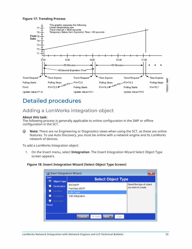
Figure 17: Trending Process
Detailed procedures
Adding a LonWorks integration objectAbout this task: The following process is generally applicable to online configuration in the SMP or offlineconfiguration in the SCT.
Note: There are no Engineering or Diagnostics views when using the SCT, as these are onlinefeatures. To use Auto Discovery, you must be online with a network engine and its LonWorksnetwork of devices.
To add a LonWorks Integration object:
1. On the Insert menu, select Integration. The Insert Integration Wizard Select Object Typescreen appears.
Figure 18: Insert Integration Wizard (Select Object Type Screen)
33LonWorks Network Integration with Network Engines and LCS Technical Bulletin
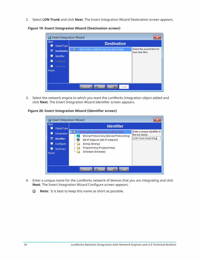
2. Select LON Trunk and click Next. The Insert Integration Wizard Destination screen appears.
Figure 19: Insert Integration Wizard (Destination screen)
3. Select the network engine to which you want the LonWorks Integration object added andclick Next. The Insert Integration Wizard Identifier screen appears.
Figure 20: Insert Integration Wizard (Identifier screen)
4. Enter a unique name for the LonWorks network of devices that you are integrating and clickNext. The Insert Integration Wizard Configure screen appears.
Note: It is best to keep this name as short as possible.
LonWorks Network Integration with Network Engines and LCS Technical Bulletin34
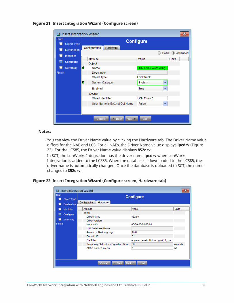
Figure 21: Insert Integration Wizard (Configure screen)
Notes:
- You can view the Driver Name value by clicking the Hardware tab. The Driver Name valuediffers for the NAE and LCS. For all NAEs, the Driver Name value displays lpcdrv (Figure22). For the LCS85, the Driver Name value displays 852drv.
- In SCT, the LonWorks Integration has the driver name lpcdrv when LonWorksIntegration is added to the LCS85. When the database is downloaded to the LCS85, thedriver name is automatically changed. Once the database is uploaded to SCT, the namechanges to 852drv.
Figure 22: Insert Integration Wizard (Configure screen, Hardware tab)
35LonWorks Network Integration with Network Engines and LCS Technical Bulletin
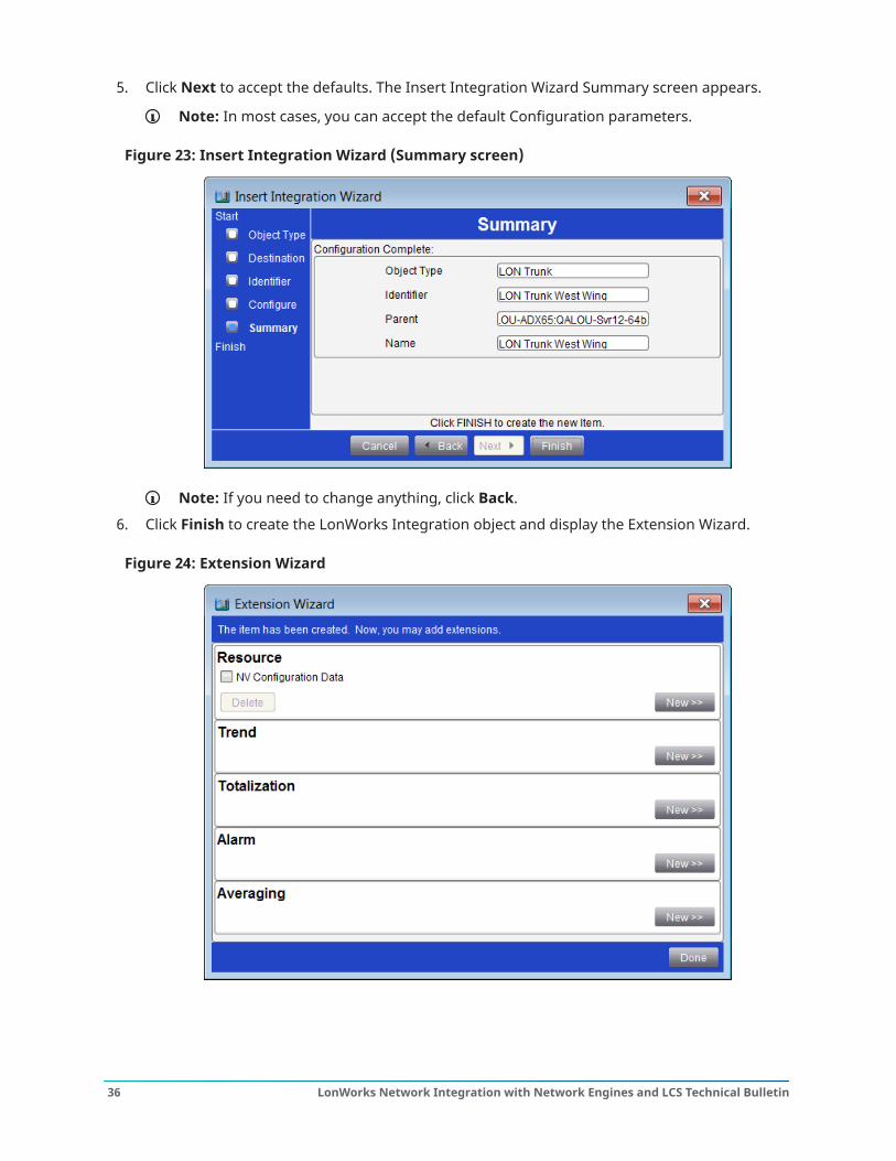
5. Click Next to accept the defaults. The Insert Integration Wizard Summary screen appears.
Note: In most cases, you can accept the default Configuration parameters.
Figure 23: Insert Integration Wizard (Summary screen)
Note: If you need to change anything, click Back.
6. Click Finish to create the LonWorks Integration object and display the Extension Wizard.
Figure 24: Extension Wizard
LonWorks Network Integration with Network Engines and LCS Technical Bulletin36
Notes:
- At this time, you can add resource files, trend, totalization, or alarm extensions to thenew LonWorks Integration object.
- The NV Configuration Data file shown in Figure 24 is created automatically, but you mustupdate it with the correct configuration data using a network configuration tool, such asLN Builder. See Defining a network engine on the LonWorks trunk.
7. Add all required resource files. See the Inserting resource files section for details.8. Add any desired alarm extensions and click Done when finished. The Insert Integration
Wizard closes.
Inserting resource filesAbout this task:
Note: If you insert a resource file under a device that has already been mapped, you mustreboot the network engine. A reboot is not required if the resource file is added before thedevice is mapped.
See Resource files for more information about resource files.
To insert resource files:
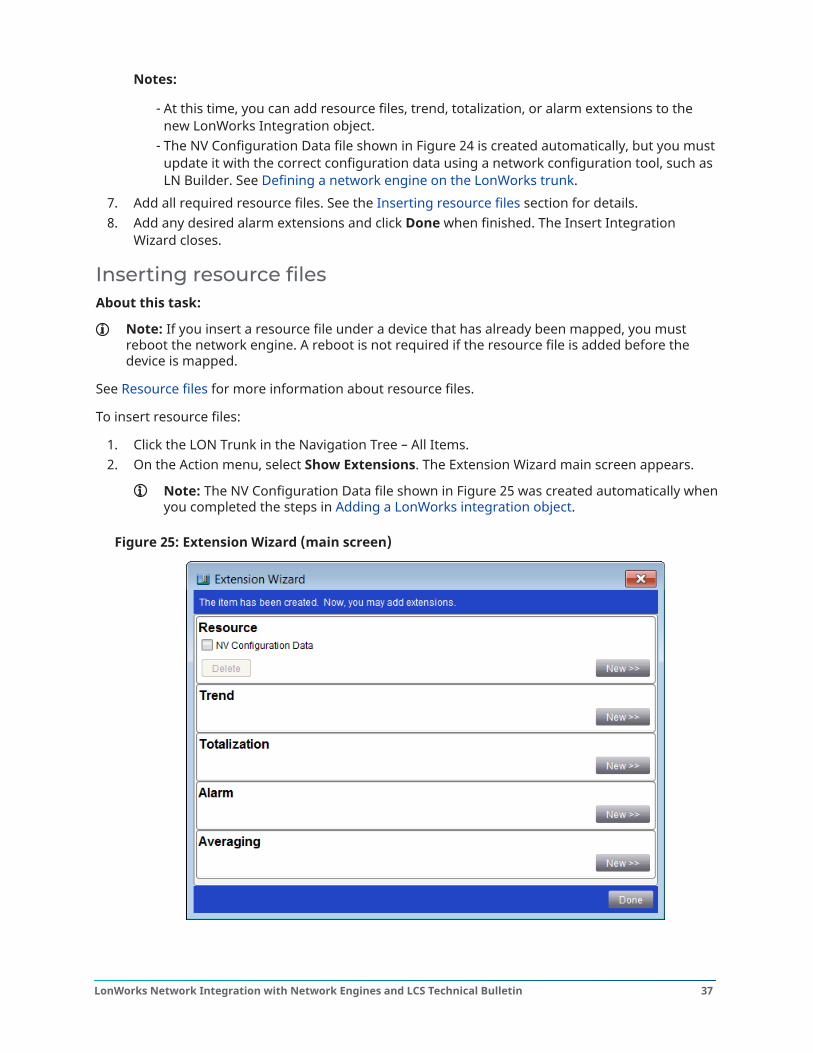
1. Click the LON Trunk in the Navigation Tree – All Items.2. On the Action menu, select Show Extensions. The Extension Wizard main screen appears.
Note: The NV Configuration Data file shown in Figure 25 was created automatically whenyou completed the steps in Adding a LonWorks integration object.
Figure 25: Extension Wizard (main screen)
37LonWorks Network Integration with Network Engines and LCS Technical Bulletin
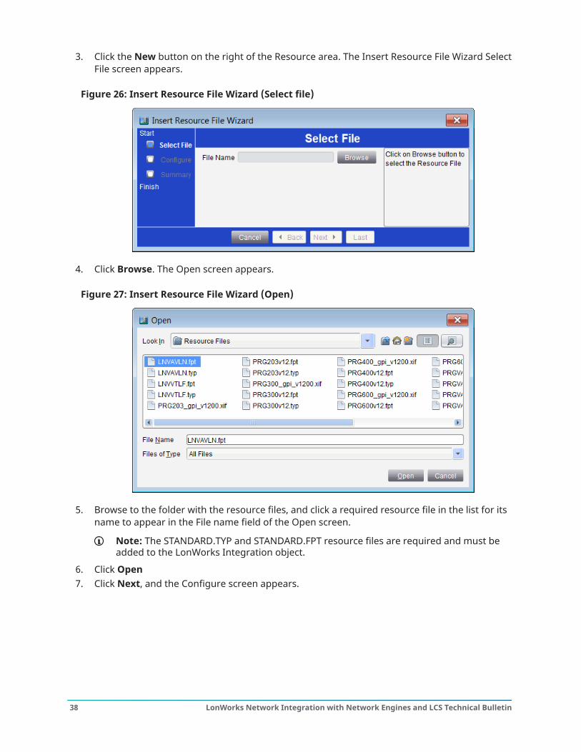
3. Click the New button on the right of the Resource area. The Insert Resource File Wizard SelectFile screen appears.
Figure 26: Insert Resource File Wizard (Select file)
4. Click Browse. The Open screen appears.
Figure 27: Insert Resource File Wizard (Open)
5. Browse to the folder with the resource files, and click a required resource file in the list for itsname to appear in the File name field of the Open screen.
Note: The STANDARD.TYP and STANDARD.FPT resource files are required and must beadded to the LonWorks Integration object.
6. Click Open7. Click Next, and the Configure screen appears.
LonWorks Network Integration with Network Engines and LCS Technical Bulletin38
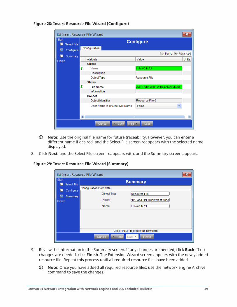
Figure 28: Insert Resource File Wizard (Configure)
Note: Use the original file name for future traceability. However, you can enter adifferent name if desired, and the Select File screen reappears with the selected namedisplayed.
8. Click Next, and the Select File screen reappears with, and the Summary screen appears.
Figure 29: Insert Resource File Wizard (Summary)
9. Review the information in the Summary screen. If any changes are needed, click Back. If nochanges are needed, click Finish. The Extension Wizard screen appears with the newly addedresource file. Repeat this process until all required resource files have been added.
Note: Once you have added all required resource files, use the network engine Archivecommand to save the changes.
39LonWorks Network Integration with Network Engines and LCS Technical Bulletin
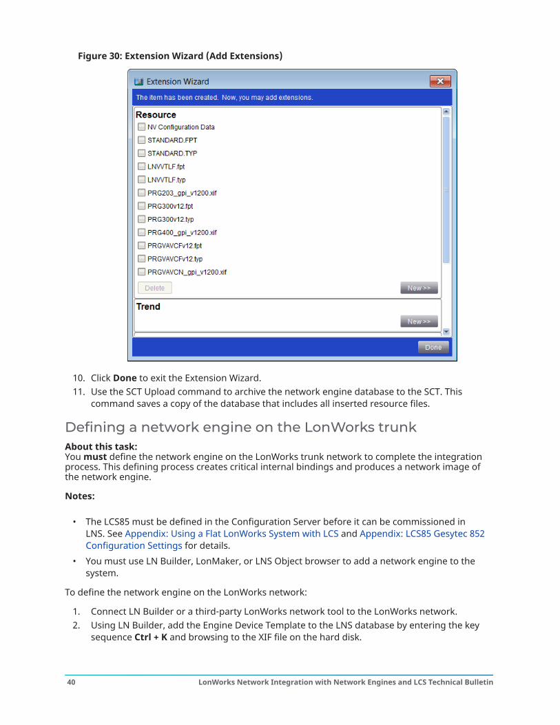
Figure 30: Extension Wizard (Add Extensions)
10. Click Done to exit the Extension Wizard.11. Use the SCT Upload command to archive the network engine database to the SCT. This
command saves a copy of the database that includes all inserted resource files.
Defining a network engine on the LonWorks trunkAbout this task: You must define the network engine on the LonWorks trunk network to complete the integrationprocess. This defining process creates critical internal bindings and produces a network image ofthe network engine.
Notes:
• The LCS85 must be defined in the Configuration Server before it can be commissioned inLNS. See Appendix: Using a Flat LonWorks System with LCS and Appendix: LCS85 Gesytec 852Configuration Settings for details.
• You must use LN Builder, LonMaker, or LNS Object browser to add a network engine to thesystem.
To define the network engine on the LonWorks network:
1. Connect LN Builder or a third-party LonWorks network tool to the LonWorks network.2. Using LN Builder, add the Engine Device Template to the LNS database by entering the key
sequence Ctrl + K and browsing to the XIF file on the hard disk.
LonWorks Network Integration with Network Engines and LCS Technical Bulletin40
3. Using LN Builder, add the network engine to either an existing Subsystem or create a newSubsystem for the network engine. The network engine can be commissioned during thisprocess provided the Neuron® ID is known and the network engine is online.
Note: The Neuron ID of the LCS can be found on the top label of the server. The NeuronID of the NAE can be found on the front label of the NAE. For SNC and SNE engines,use the Neuron ID that can be found on the back label of the connected USB-to-LONinterface adapter.
4. Continue advancing through each section making sure to select the correct Channel, thecorrect Device Template, and manually entering the correct Neuron ID.
5. Click Finish to complete the process.
Note: Refer to the third-party LonWorks network tool documentation for the equivalentcommands in Steps 2, 3, and 4.
6. Archive the changes in the SMP UI.7. Upload the network engine database to the SCT archive database.
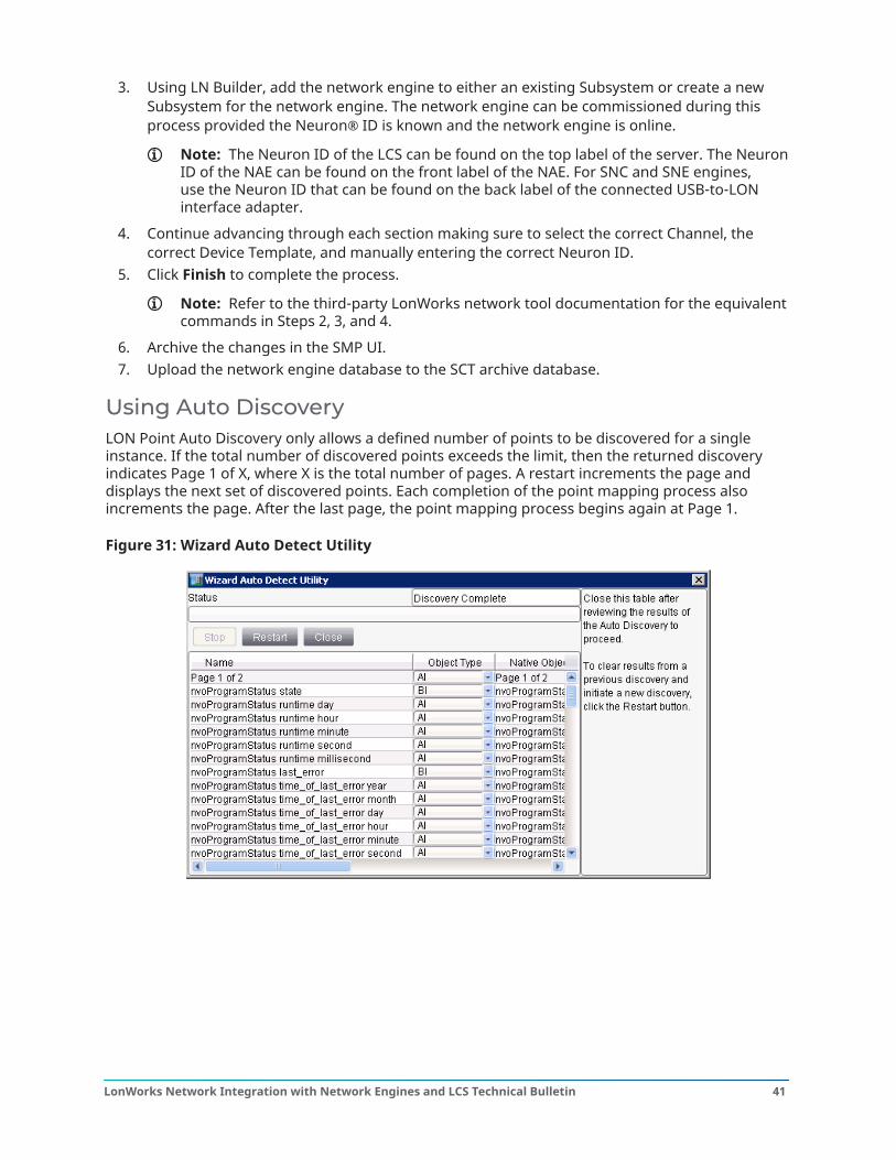
Using Auto DiscoveryLON Point Auto Discovery only allows a defined number of points to be discovered for a singleinstance. If the total number of discovered points exceeds the limit, then the returned discoveryindicates Page 1 of X, where X is the total number of pages. A restart increments the page anddisplays the next set of discovered points. Each completion of the point mapping process alsoincrements the page. After the last page, the point mapping process begins again at Page 1.
Figure 31: Wizard Auto Detect Utility
41LonWorks Network Integration with Network Engines and LCS Technical Bulletin
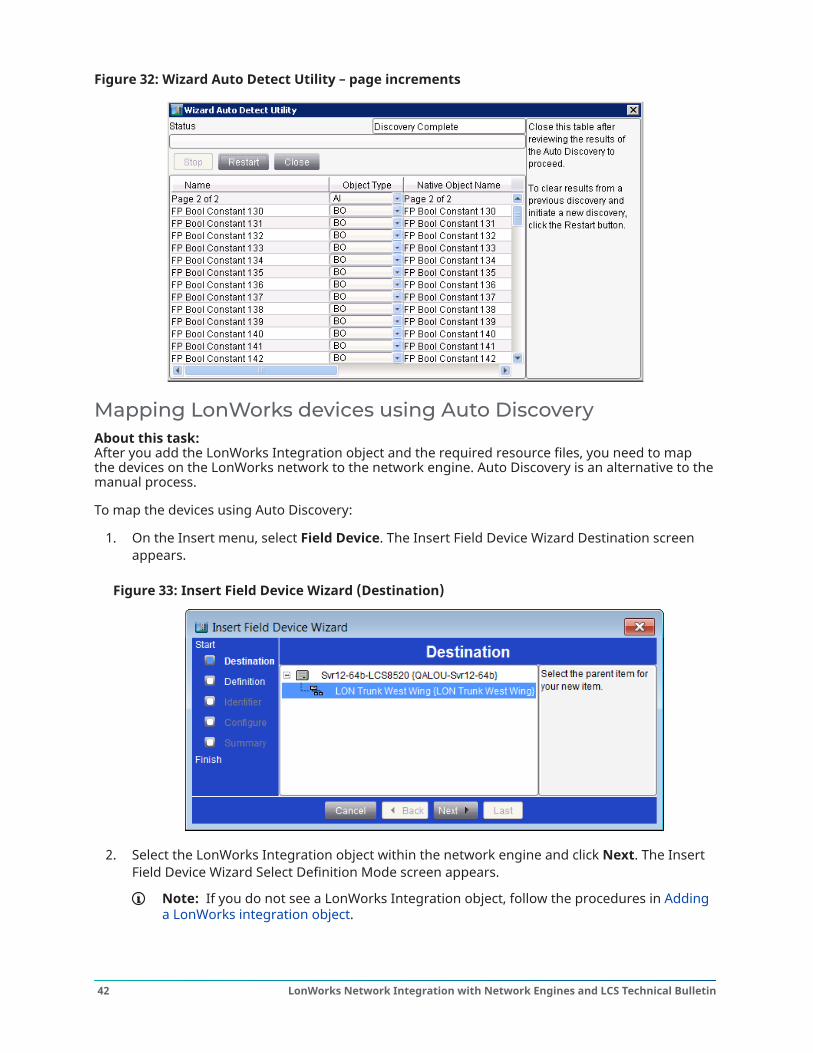
Figure 32: Wizard Auto Detect Utility – page increments
Mapping LonWorks devices using Auto DiscoveryAbout this task: After you add the LonWorks Integration object and the required resource files, you need to mapthe devices on the LonWorks network to the network engine. Auto Discovery is an alternative to themanual process.
To map the devices using Auto Discovery:
1. On the Insert menu, select Field Device. The Insert Field Device Wizard Destination screenappears.
Figure 33: Insert Field Device Wizard (Destination)
2. Select the LonWorks Integration object within the network engine and click Next. The InsertField Device Wizard Select Definition Mode screen appears.
Note: If you do not see a LonWorks Integration object, follow the procedures in Addinga LonWorks integration object.
LonWorks Network Integration with Network Engines and LCS Technical Bulletin42
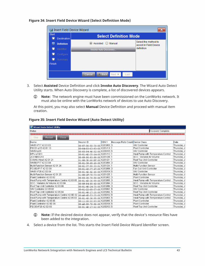
Figure 34: Insert Field Device Wizard (Select Definition Mode)
3. Select Assisted Device Definition and click Invoke Auto Discovery. The Wizard Auto DetectUtility starts. When Auto Discovery is complete, a list of discovered devices appears.
Note: The network engine must have been commissioned on the LonWorks network. Itmust also be online with the LonWorks network of devices to use Auto Discovery.
At this point, you may also select Manual Device Definition and proceed with manual itemcreation.
Figure 35: Insert Field Device Wizard (Auto Detect Utility)
Note: If the desired device does not appear, verify that the device's resource files havebeen added to the integration.
4. Select a device from the list. This starts the Insert Field Device Wizard Identifier screen.
43LonWorks Network Integration with Network Engines and LCS Technical Bulletin

Figure 36: Insert Field Device Wizard (Identifier)
5. Enter an identifier for the device that is unique on this LonWorks trunk.
Note:
Always replace the existing default identifier found in the identifier box because this isthe generic device-type name and may not be unique on the trunk. Identifier names arelimited to 32 characters.
The identifier you enter is displayed in the device’s Advanced Focus view under theEngineering Values - Item Reference listing.
The DSN number in the identifier is used to identify which subnet a device is on whenrouters are present. The DSN number is removable.
6. Click Next and the Insert Field Device Wizard Configure screen appears.
LonWorks Network Integration with Network Engines and LCS Technical Bulletin44
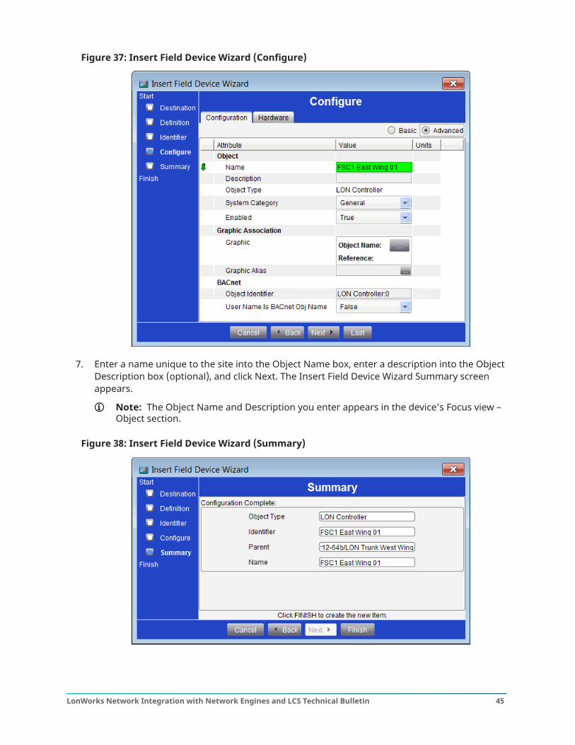
Figure 37: Insert Field Device Wizard (Configure)
7. Enter a name unique to the site into the Object Name box, enter a description into the ObjectDescription box (optional), and click Next. The Insert Field Device Wizard Summary screenappears.
Note: The Object Name and Description you enter appears in the device’s Focus view –Object section.
Figure 38: Insert Field Device Wizard (Summary)
45LonWorks Network Integration with Network Engines and LCS Technical Bulletin
8. Review the configuration information. Click Back to make any changes. Click Finish and theExtension Wizard appears.
9. Add any extensions and click Done. This saves the field device’s configuration, and the FieldDevice Extension - Field Points screen appears. See Mapping Field Points in LonWorks devicesusing Auto Discovery.
Mapping Field Points in LonWorks devices using AutoDiscoveryAbout this task: Once one or more integrated LonWorks device objects have been configured, you can addLonWorks Field Points, which map to network variables in the LonWorks device.
To map field points in LonWorks devices using Auto Discovery:
Note: The network engine must be online with the LonWorks network of devices in order touse Auto Discovery. If you are mapping points offline, see Manually mapping Field Points inLonWorks enabled devices.
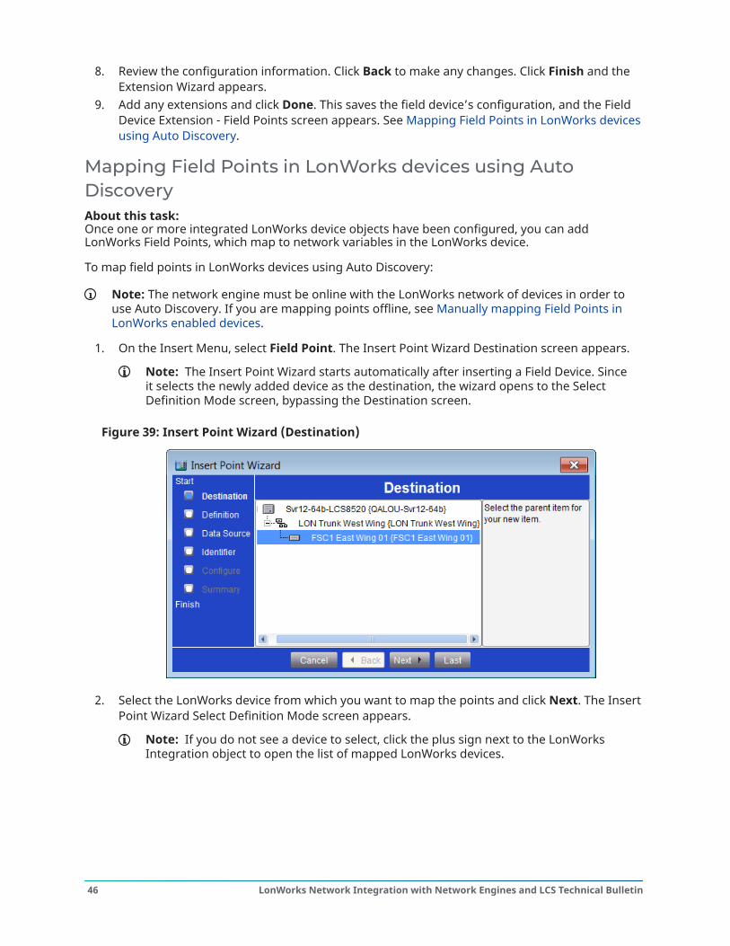
1. On the Insert Menu, select Field Point. The Insert Point Wizard Destination screen appears.
Note: The Insert Point Wizard starts automatically after inserting a Field Device. Sinceit selects the newly added device as the destination, the wizard opens to the SelectDefinition Mode screen, bypassing the Destination screen.
Figure 39: Insert Point Wizard (Destination)
2. Select the LonWorks device from which you want to map the points and click Next. The InsertPoint Wizard Select Definition Mode screen appears.
Note: If you do not see a device to select, click the plus sign next to the LonWorksIntegration object to open the list of mapped LonWorks devices.
LonWorks Network Integration with Network Engines and LCS Technical Bulletin46
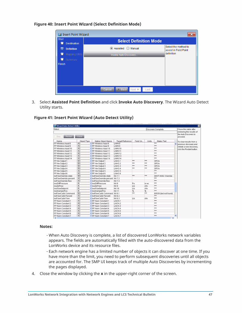
Figure 40: Insert Point Wizard (Select Definition Mode)
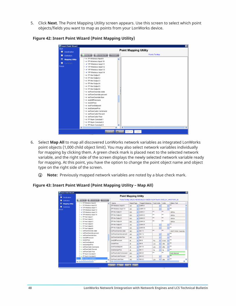
3. Select Assisted Point Definition and click Invoke Auto Discovery. The Wizard Auto DetectUtility starts.
Figure 41: Insert Point Wizard (Auto Detect Utility)
Notes:
- When Auto Discovery is complete, a list of discovered LonWorks network variablesappears. The fields are automatically filled with the auto-discovered data from theLonWorks device and its resource files.
- Each network engine has a limited number of objects it can discover at one time. If youhave more than the limit, you need to perform subsequent discoveries until all objectsare accounted for. The SMP UI keeps track of multiple Auto Discoveries by incrementingthe pages displayed.
4. Close the window by clicking the x in the upper-right corner of the screen.
47LonWorks Network Integration with Network Engines and LCS Technical Bulletin
5. Click Next. The Point Mapping Utility screen appears. Use this screen to select which pointobjects/fields you want to map as points from your LonWorks device.
Figure 42: Insert Point Wizard (Point Mapping Utility)
6. Select Map All to map all discovered LonWorks network variables as integrated LonWorkspoint objects (1,000 child object limit). You may also select network variables individuallyfor mapping by clicking them. A green check mark is placed next to the selected networkvariable, and the right side of the screen displays the newly selected network variable readyfor mapping. At this point, you have the option to change the point object name and objecttype on the right side of the screen.
Note: Previously mapped network variables are noted by a blue check mark.
Figure 43: Insert Point Wizard (Point Mapping Utility – Map All)
LonWorks Network Integration with Network Engines and LCS Technical Bulletin48
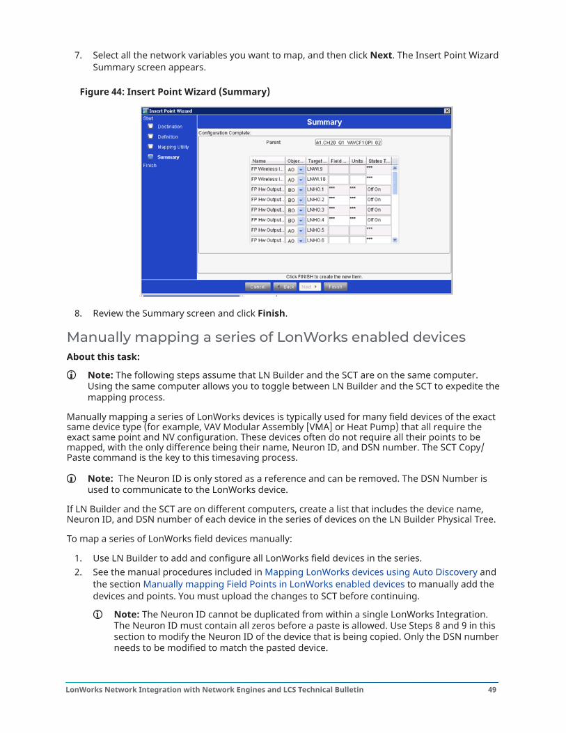
7. Select all the network variables you want to map, and then click Next. The Insert Point WizardSummary screen appears.
Figure 44: Insert Point Wizard (Summary)
8. Review the Summary screen and click Finish.
Manually mapping a series of LonWorks enabled devicesAbout this task:
Note: The following steps assume that LN Builder and the SCT are on the same computer.Using the same computer allows you to toggle between LN Builder and the SCT to expedite themapping process.
Manually mapping a series of LonWorks devices is typically used for many field devices of the exactsame device type (for example, VAV Modular Assembly [VMA] or Heat Pump) that all require theexact same point and NV configuration. These devices often do not require all their points to bemapped, with the only difference being their name, Neuron ID, and DSN number. The SCT Copy/Paste command is the key to this timesaving process.
Note: The Neuron ID is only stored as a reference and can be removed. The DSN Number isused to communicate to the LonWorks device.
If LN Builder and the SCT are on different computers, create a list that includes the device name,Neuron ID, and DSN number of each device in the series of devices on the LN Builder Physical Tree.
To map a series of LonWorks field devices manually:
1. Use LN Builder to add and configure all LonWorks field devices in the series.2. See the manual procedures included in Mapping LonWorks devices using Auto Discovery and
the section Manually mapping Field Points in LonWorks enabled devices to manually add thedevices and points. You must upload the changes to SCT before continuing.
Note: The Neuron ID cannot be duplicated from within a single LonWorks Integration.The Neuron ID must contain all zeros before a paste is allowed. Use Steps 8 and 9 in thissection to modify the Neuron ID of the device that is being copied. Only the DSN numberneeds to be modified to match the pasted device.
49LonWorks Network Integration with Network Engines and LCS Technical Bulletin
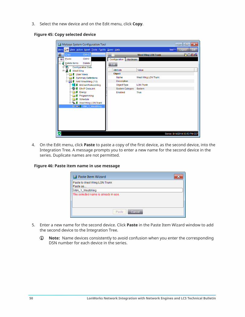
3. Select the new device and on the Edit menu, click Copy.
Figure 45: Copy selected device
4. On the Edit menu, click Paste to paste a copy of the first device, as the second device, into theIntegration Tree. A message prompts you to enter a new name for the second device in theseries. Duplicate names are not permitted.
Figure 46: Paste item name in use message
5. Enter a new name for the second device. Click Paste in the Paste Item Wizard window to addthe second device to the Integration Tree.
Note: Name devices consistently to avoid confusion when you enter the correspondingDSN number for each device in the series.
LonWorks Network Integration with Network Engines and LCS Technical Bulletin50
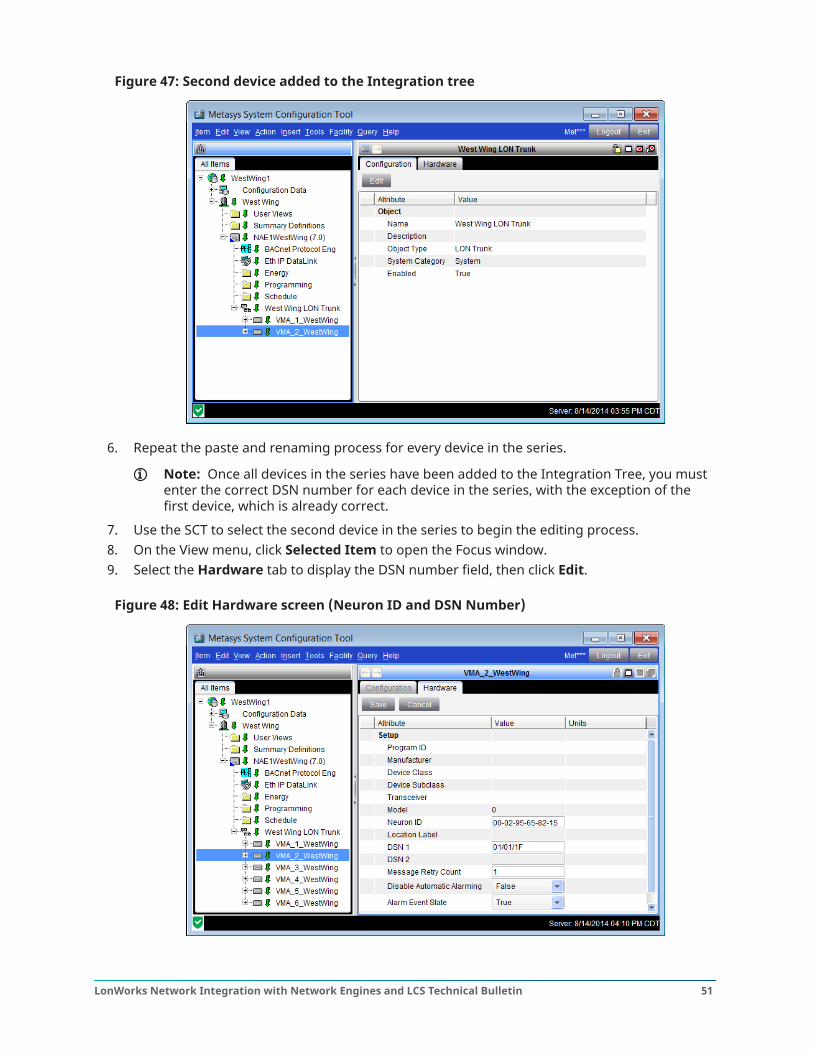
Figure 47: Second device added to the Integration tree
6. Repeat the paste and renaming process for every device in the series.
Note: Once all devices in the series have been added to the Integration Tree, you mustenter the correct DSN number for each device in the series, with the exception of thefirst device, which is already correct.
7. Use the SCT to select the second device in the series to begin the editing process.8. On the View menu, click Selected Item to open the Focus window.9. Select the Hardware tab to display the DSN number field, then click Edit.
Figure 48: Edit Hardware screen (Neuron ID and DSN Number)
51LonWorks Network Integration with Network Engines and LCS Technical Bulletin
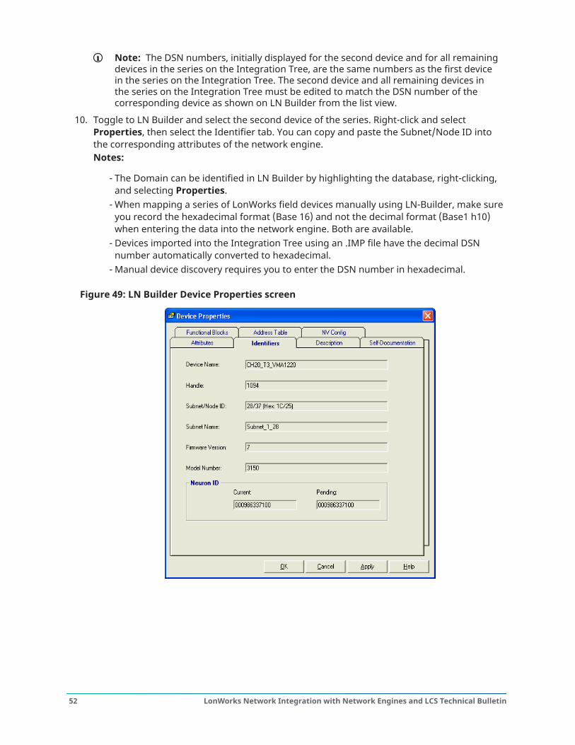
Note: The DSN numbers, initially displayed for the second device and for all remainingdevices in the series on the Integration Tree, are the same numbers as the first devicein the series on the Integration Tree. The second device and all remaining devices inthe series on the Integration Tree must be edited to match the DSN number of thecorresponding device as shown on LN Builder from the list view.
10. Toggle to LN Builder and select the second device of the series. Right-click and selectProperties, then select the Identifier tab. You can copy and paste the Subnet/Node ID intothe corresponding attributes of the network engine.Notes:
- The Domain can be identified in LN Builder by highlighting the database, right-clicking,and selecting Properties.
- When mapping a series of LonWorks field devices manually using LN-Builder, make sureyou record the hexadecimal format (Base 16) and not the decimal format (Base1 h10)when entering the data into the network engine. Both are available.
- Devices imported into the Integration Tree using an .IMP file have the decimal DSNnumber automatically converted to hexadecimal.
- Manual device discovery requires you to enter the DSN number in hexadecimal.
Figure 49: LN Builder Device Properties screen
LonWorks Network Integration with Network Engines and LCS Technical Bulletin52
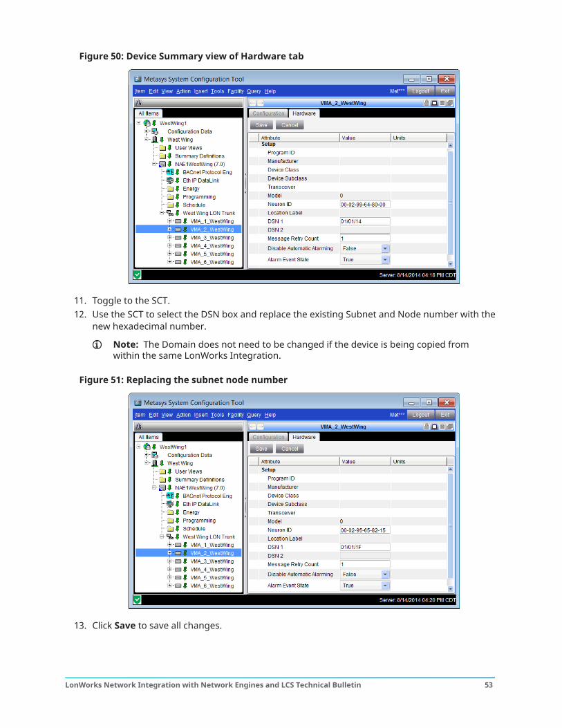
Figure 50: Device Summary view of Hardware tab
11. Toggle to the SCT.12. Use the SCT to select the DSN box and replace the existing Subnet and Node number with the
new hexadecimal number.
Note: The Domain does not need to be changed if the device is being copied fromwithin the same LonWorks Integration.
Figure 51: Replacing the subnet node number
13. Click Save to save all changes.
53LonWorks Network Integration with Network Engines and LCS Technical Bulletin
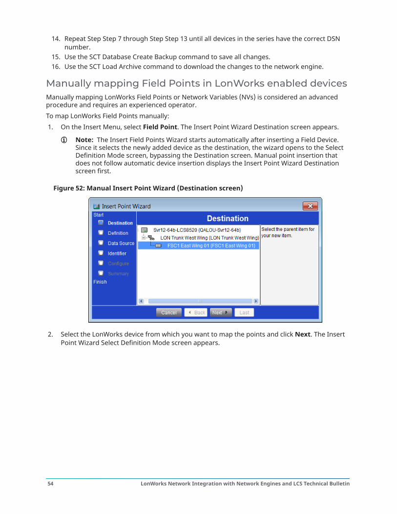
14. Repeat Step Step 7 through Step Step 13 until all devices in the series have the correct DSNnumber.
15. Use the SCT Database Create Backup command to save all changes.16. Use the SCT Load Archive command to download the changes to the network engine.
Manually mapping Field Points in LonWorks enabled devicesManually mapping LonWorks Field Points or Network Variables (NVs) is considered an advancedprocedure and requires an experienced operator.To map LonWorks Field Points manually:1. On the Insert Menu, select Field Point. The Insert Point Wizard Destination screen appears.
Note: The Insert Field Points Wizard starts automatically after inserting a Field Device.Since it selects the newly added device as the destination, the wizard opens to the SelectDefinition Mode screen, bypassing the Destination screen. Manual point insertion thatdoes not follow automatic device insertion displays the Insert Point Wizard Destinationscreen first.
Figure 52: Manual Insert Point Wizard (Destination screen)
2. Select the LonWorks device from which you want to map the points and click Next. The InsertPoint Wizard Select Definition Mode screen appears.
LonWorks Network Integration with Network Engines and LCS Technical Bulletin54
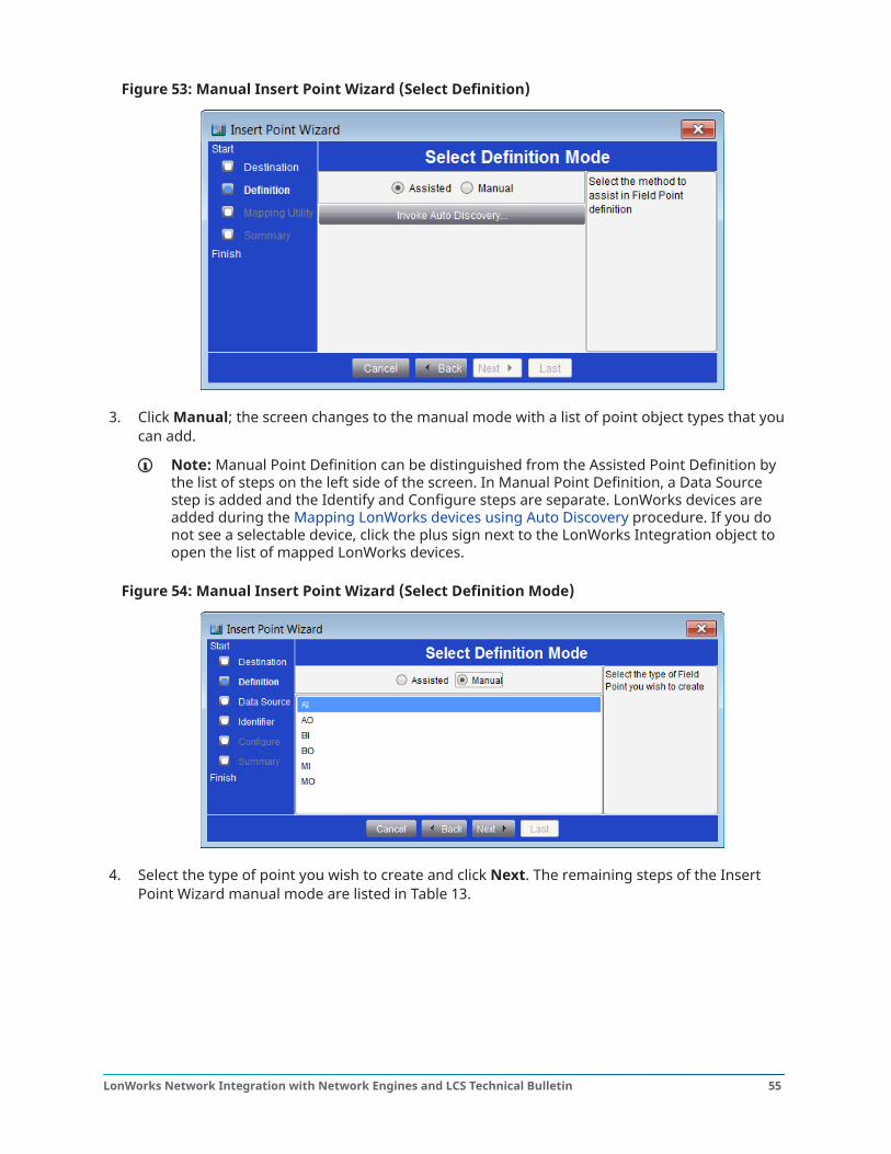
Figure 53: Manual Insert Point Wizard (Select Definition)
3. Click Manual; the screen changes to the manual mode with a list of point object types that youcan add.
Note: Manual Point Definition can be distinguished from the Assisted Point Definition bythe list of steps on the left side of the screen. In Manual Point Definition, a Data Sourcestep is added and the Identify and Configure steps are separate. LonWorks devices areadded during the Mapping LonWorks devices using Auto Discovery procedure. If you donot see a selectable device, click the plus sign next to the LonWorks Integration object toopen the list of mapped LonWorks devices.
Figure 54: Manual Insert Point Wizard (Select Definition Mode)
4. Select the type of point you wish to create and click Next. The remaining steps of the InsertPoint Wizard manual mode are listed in Table 13.
55LonWorks Network Integration with Network Engines and LCS Technical Bulletin
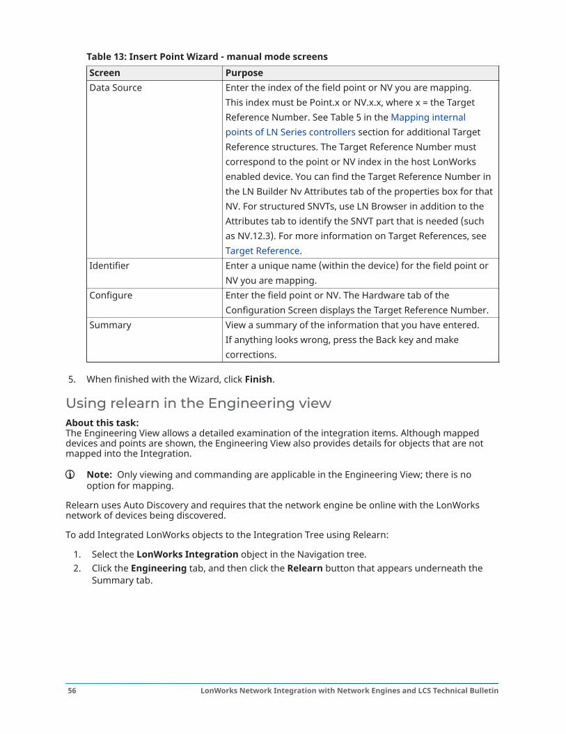
Table 13: Insert Point Wizard - manual mode screensScreen PurposeData Source Enter the index of the field point or NV you are mapping.
This index must be Point.x or NV.x.x, where x = the TargetReference Number. See Table 5 in the Mapping internalpoints of LN Series controllers section for additional TargetReference structures. The Target Reference Number mustcorrespond to the point or NV index in the host LonWorksenabled device. You can find the Target Reference Number inthe LN Builder Nv Attributes tab of the properties box for thatNV. For structured SNVTs, use LN Browser in addition to theAttributes tab to identify the SNVT part that is needed (suchas NV.12.3). For more information on Target References, seeTarget Reference.
Identifier Enter a unique name (within the device) for the field point orNV you are mapping.
Configure Enter the field point or NV. The Hardware tab of theConfiguration Screen displays the Target Reference Number.
Summary View a summary of the information that you have entered.If anything looks wrong, press the Back key and makecorrections.
5. When finished with the Wizard, click Finish.
Using relearn in the Engineering viewAbout this task: The Engineering View allows a detailed examination of the integration items. Although mappeddevices and points are shown, the Engineering View also provides details for objects that are notmapped into the Integration.
Note: Only viewing and commanding are applicable in the Engineering View; there is nooption for mapping.
Relearn uses Auto Discovery and requires that the network engine be online with the LonWorksnetwork of devices being discovered.
To add Integrated LonWorks objects to the Integration Tree using Relearn:
1. Select the LonWorks Integration object in the Navigation tree.2. Click the Engineering tab, and then click the Relearn button that appears underneath the
Summary tab.
LonWorks Network Integration with Network Engines and LCS Technical Bulletin56
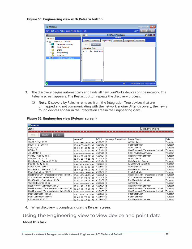
Figure 55: Engineering view with Relearn button
3. The discovery begins automatically and finds all new LonWorks devices on the network. TheRelearn screen appears. The Restart button repeats the discovery process.
Note: Discovery by Relearn removes from the Integration Tree devices that areunmapped and not communicating with the network engine. After discovery, the newlyfound devices appear in the Integration Tree in the Engineering view.
Figure 56: Engineering view (Relearn screen)
4. When discovery is complete, close the Relearn screen.
Using the Engineering view to view device and point dataAbout this task:
57LonWorks Network Integration with Network Engines and LCS Technical Bulletin
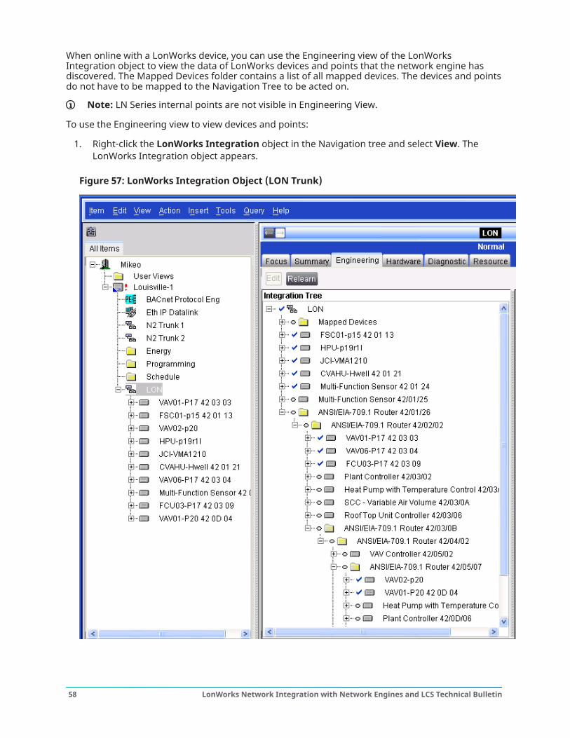
When online with a LonWorks device, you can use the Engineering view of the LonWorksIntegration object to view the data of LonWorks devices and points that the network engine hasdiscovered. The Mapped Devices folder contains a list of all mapped devices. The devices and pointsdo not have to be mapped to the Navigation Tree to be acted on.
Note: LN Series internal points are not visible in Engineering View.
To use the Engineering view to view devices and points:
1. Right-click the LonWorks Integration object in the Navigation tree and select View. TheLonWorks Integration object appears.
Figure 57: LonWorks Integration Object (LON Trunk)
LonWorks Network Integration with Network Engines and LCS Technical Bulletin58
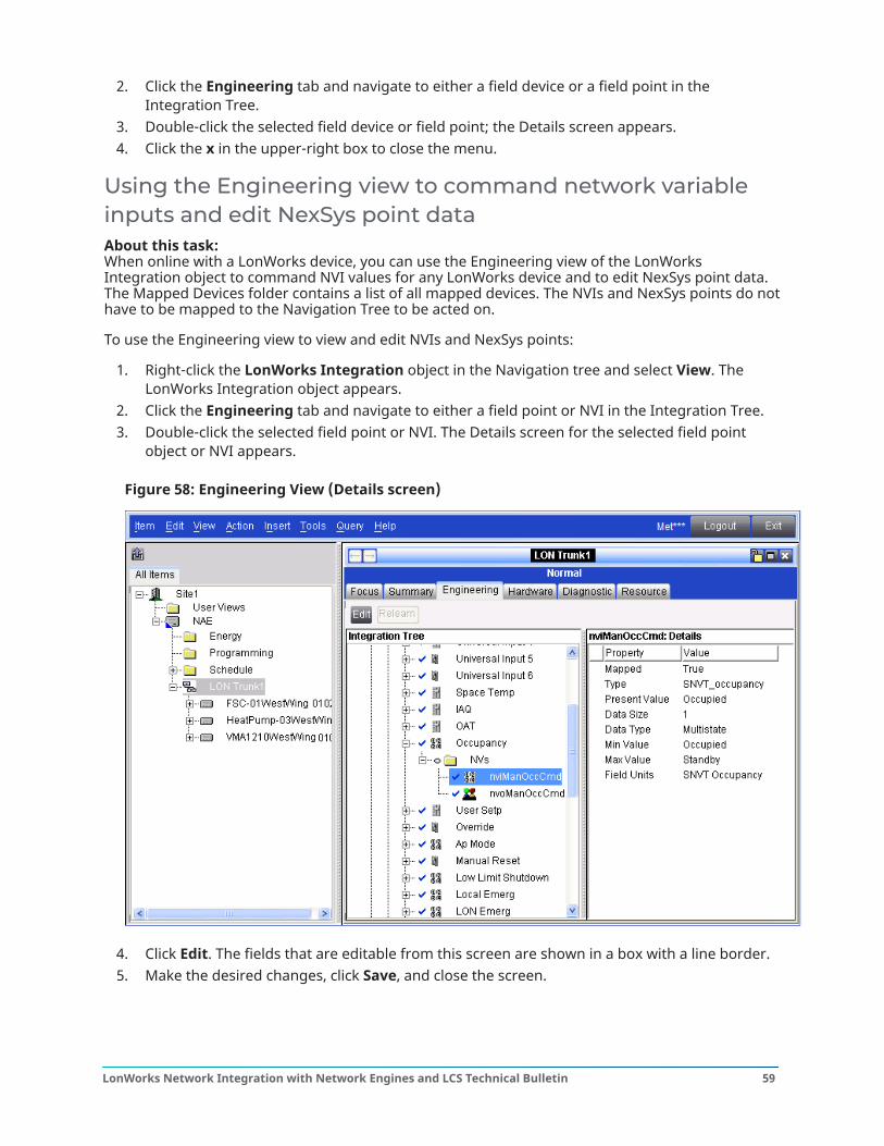
2. Click the Engineering tab and navigate to either a field device or a field point in theIntegration Tree.
3. Double-click the selected field device or field point; the Details screen appears.4. Click the x in the upper-right box to close the menu.
Using the Engineering view to command network variableinputs and edit NexSys point dataAbout this task: When online with a LonWorks device, you can use the Engineering view of the LonWorksIntegration object to command NVI values for any LonWorks device and to edit NexSys point data.The Mapped Devices folder contains a list of all mapped devices. The NVIs and NexSys points do nothave to be mapped to the Navigation Tree to be acted on.
To use the Engineering view to view and edit NVIs and NexSys points:
1. Right-click the LonWorks Integration object in the Navigation tree and select View. TheLonWorks Integration object appears.
2. Click the Engineering tab and navigate to either a field point or NVI in the Integration Tree.3. Double-click the selected field point or NVI. The Details screen for the selected field point
object or NVI appears.
Figure 58: Engineering View (Details screen)
4. Click Edit. The fields that are editable from this screen are shown in a box with a line border.5. Make the desired changes, click Save, and close the screen.
59LonWorks Network Integration with Network Engines and LCS Technical Bulletin
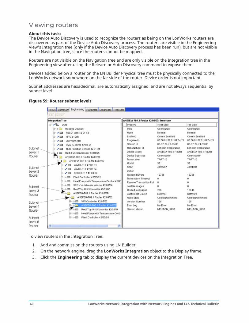
Viewing routersAbout this task: The Device Auto Discovery is used to recognize the routers as being on the LonWorks routers arediscovered as part of the Device Auto Discovery process. The routers are visible in the EngineeringView's Integration tree (only if the Device Auto Discovery process has been run), but are not visiblein the Navigation tree, since the routers cannot be mapped.
Routers are not visible on the Navigation tree and are only visible on the Integration tree in theEngineering view after using the Relearn or Auto Discovery command to expose them.
Devices added below a router on the LN Builder Physical tree must be physically connected to theLonWorks network somewhere on the far side of the router. Device order is not important.
Subnet addresses are hexadecimal, are automatically assigned, and are not always sequential bysubnet level.
Figure 59: Router subnet levels
To view routers in the Integration Tree:
1. Add and commission the routers using LN Builder.2. On the network engine, drag the LonWorks Integration object to the Display frame.3. Click the Engineering tab to display the current devices on the Integration Tree.
LonWorks Network Integration with Network Engines and LCS Technical Bulletin60
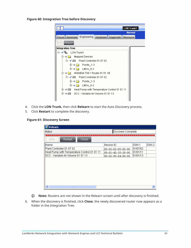
Figure 60: Integration Tree before Discovery
4. Click the LON Trunk, then click Relearn to start the Auto Discovery process.5. Click Restart to complete the discovery.
Figure 61: Discovery Screen
Note: Routers are not shown in the Relearn screen until after discovery is finished.
6. When the discovery is finished, click Close; the newly discovered router now appears as afolder in the Integration Tree.
61LonWorks Network Integration with Network Engines and LCS Technical Bulletin
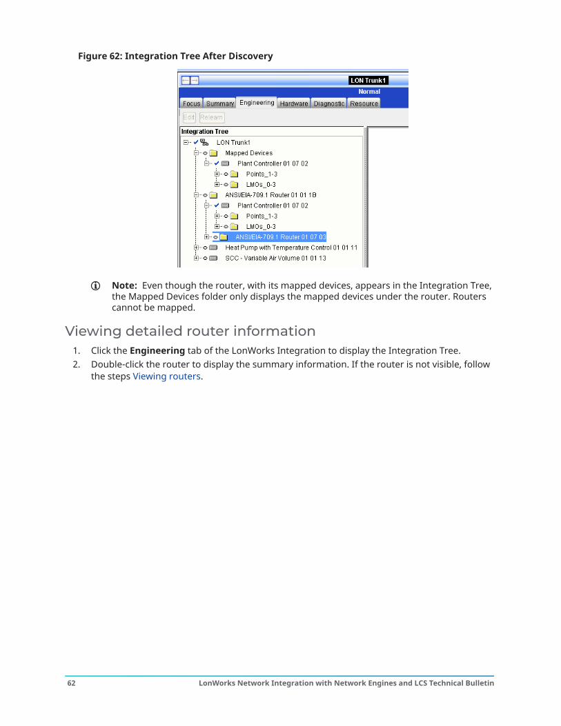
Figure 62: Integration Tree After Discovery
Note: Even though the router, with its mapped devices, appears in the Integration Tree,the Mapped Devices folder only displays the mapped devices under the router. Routerscannot be mapped.
Viewing detailed router information1. Click the Engineering tab of the LonWorks Integration to display the Integration Tree.2. Double-click the router to display the summary information. If the router is not visible, follow
the steps Viewing routers.
LonWorks Network Integration with Network Engines and LCS Technical Bulletin62
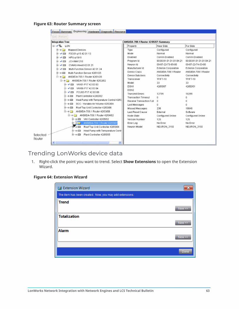
Figure 63: Router Summary screen
Trending LonWorks device data1. Right-click the point you want to trend. Select Show Extensions to open the Extension
Wizard.
Figure 64: Extension Wizard
63LonWorks Network Integration with Network Engines and LCS Technical Bulletin
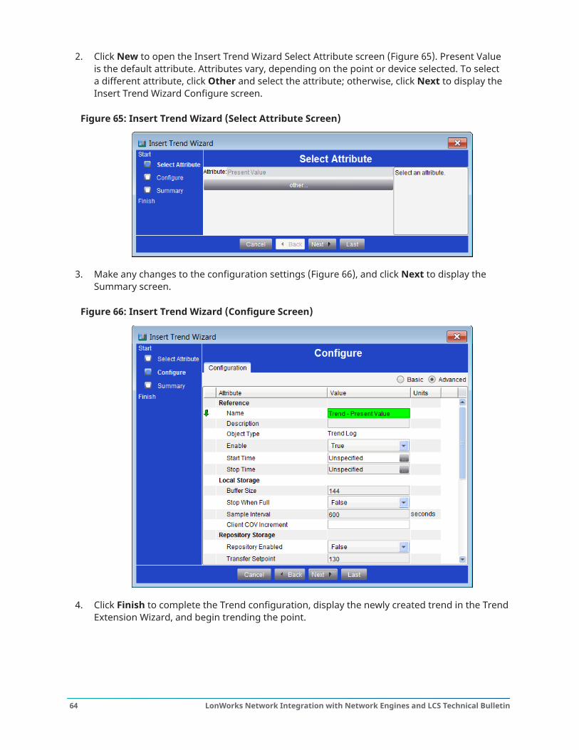
2. Click New to open the Insert Trend Wizard Select Attribute screen (Figure 65). Present Valueis the default attribute. Attributes vary, depending on the point or device selected. To selecta different attribute, click Other and select the attribute; otherwise, click Next to display theInsert Trend Wizard Configure screen.
Figure 65: Insert Trend Wizard (Select Attribute Screen)
3. Make any changes to the configuration settings (Figure 66), and click Next to display theSummary screen.
Figure 66: Insert Trend Wizard (Configure Screen)
4. Click Finish to complete the Trend configuration, display the newly created trend in the TrendExtension Wizard, and begin trending the point.
LonWorks Network Integration with Network Engines and LCS Technical Bulletin64
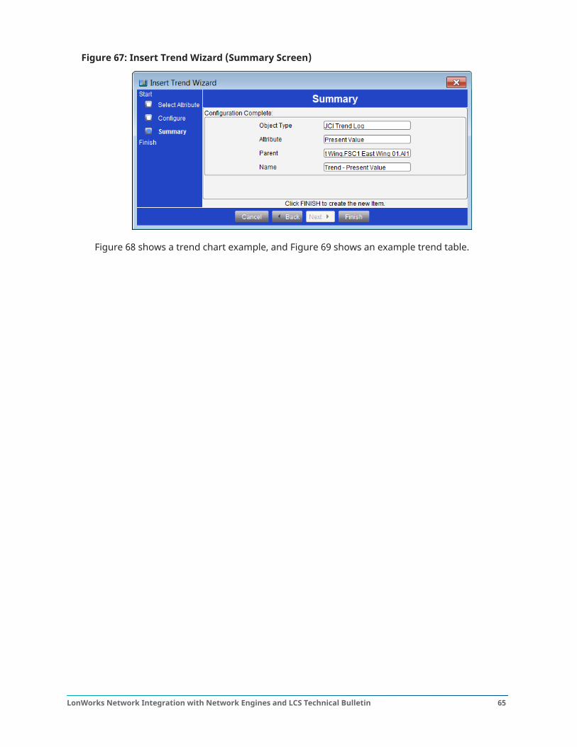
Figure 67: Insert Trend Wizard (Summary Screen)
Figure 68 shows a trend chart example, and Figure 69 shows an example trend table.
65LonWorks Network Integration with Network Engines and LCS Technical Bulletin
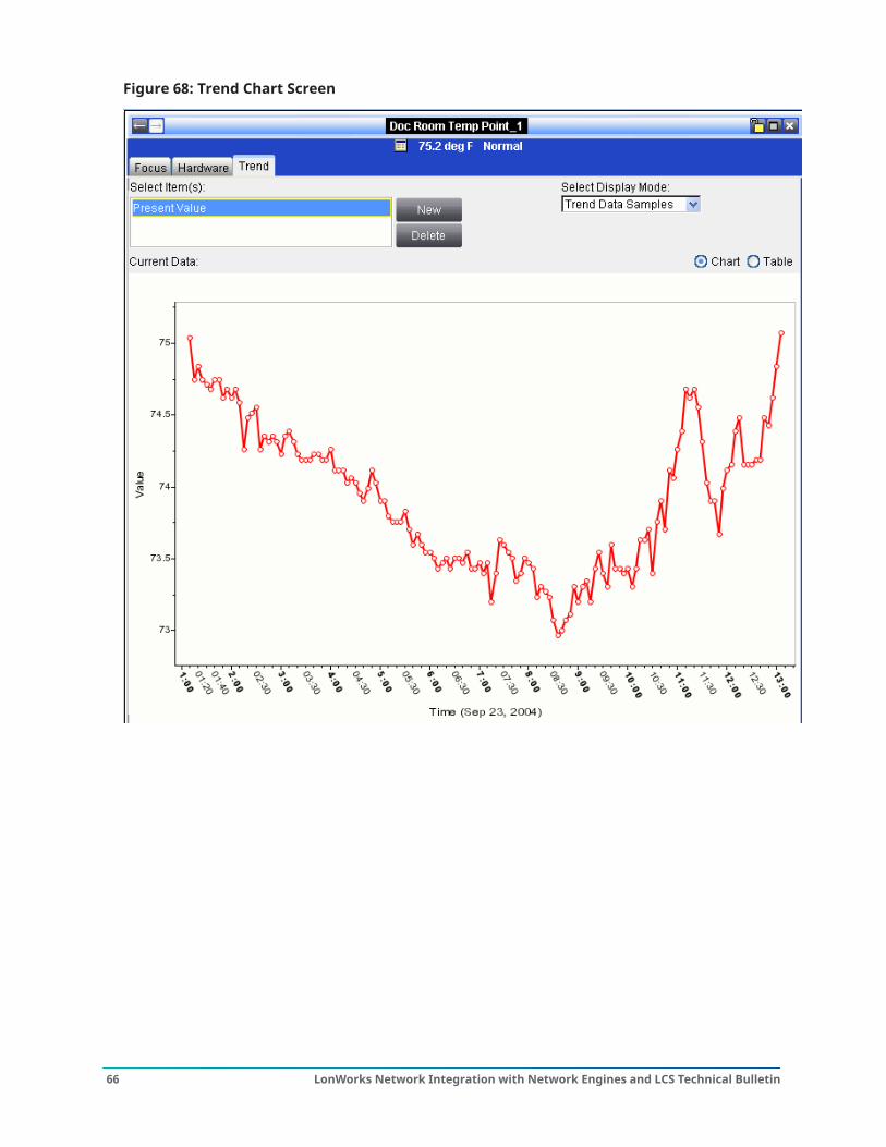
Figure 68: Trend Chart Screen
LonWorks Network Integration with Network Engines and LCS Technical Bulletin66
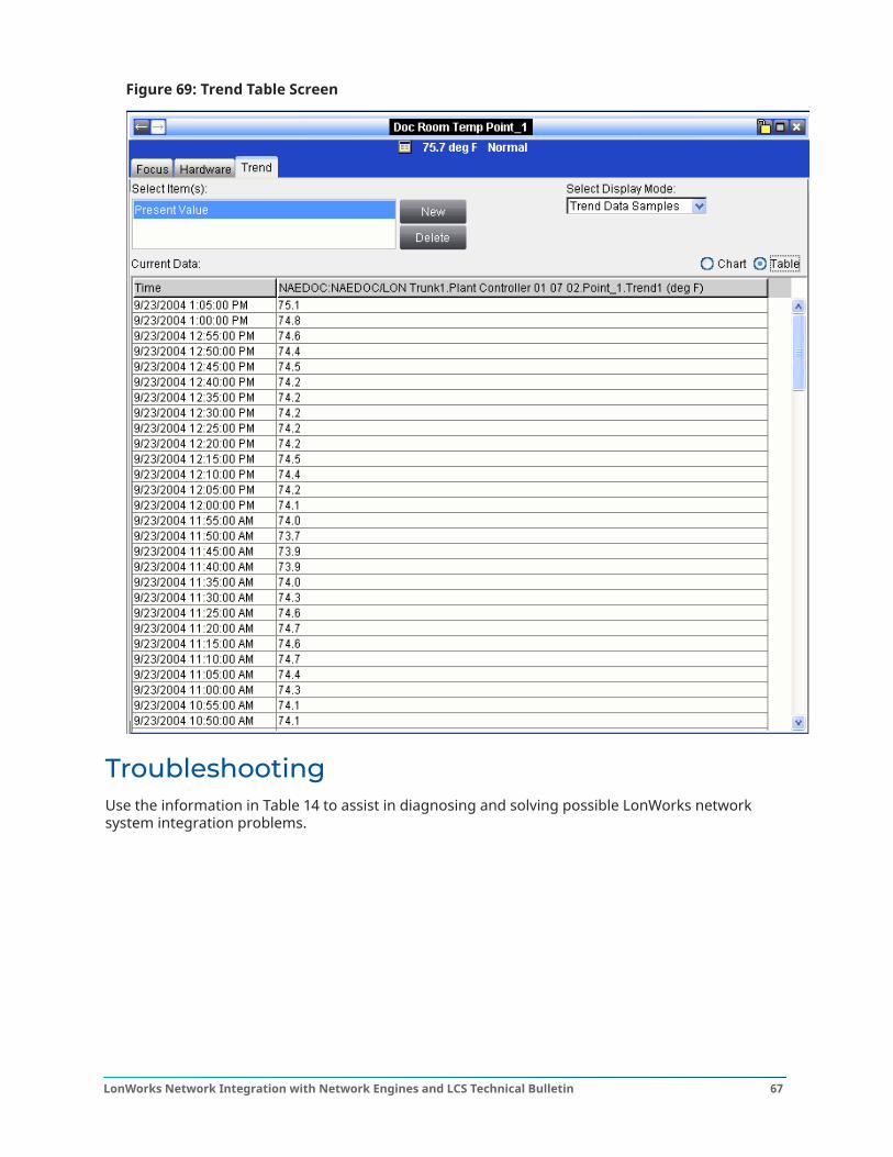
Figure 69: Trend Table Screen
TroubleshootingUse the information in Table 14 to assist in diagnosing and solving possible LonWorks networksystem integration problems.
67LonWorks Network Integration with Network Engines and LCS Technical Bulletin
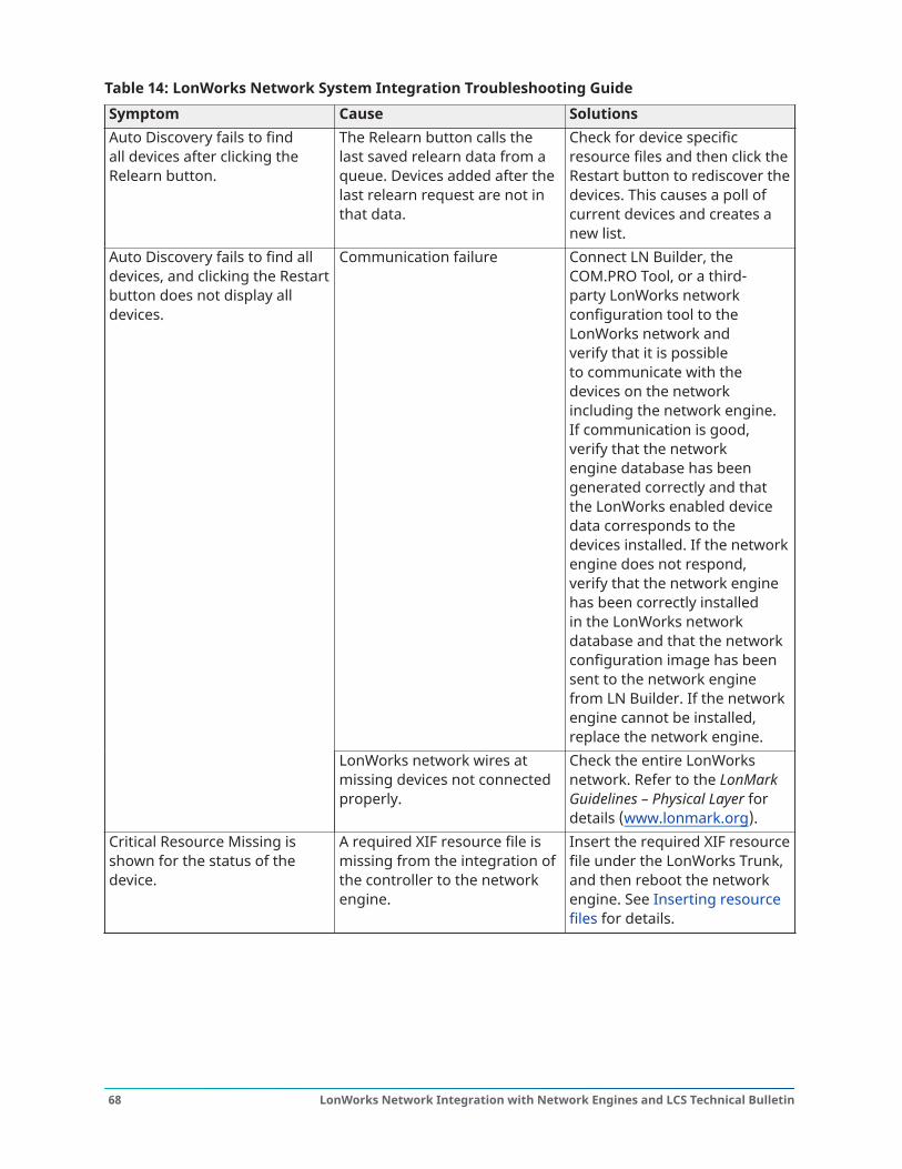
Table 14: LonWorks Network System Integration Troubleshooting GuideSymptom Cause SolutionsAuto Discovery fails to findall devices after clicking theRelearn button.
The Relearn button calls thelast saved relearn data from aqueue. Devices added after thelast relearn request are not inthat data.
Check for device specificresource files and then click theRestart button to rediscover thedevices. This causes a poll ofcurrent devices and creates anew list.
Communication failure Connect LN Builder, theCOM.PRO Tool, or a third-party LonWorks networkconfiguration tool to theLonWorks network andverify that it is possibleto communicate with thedevices on the networkincluding the network engine.If communication is good,verify that the networkengine database has beengenerated correctly and thatthe LonWorks enabled devicedata corresponds to thedevices installed. If the networkengine does not respond,verify that the network enginehas been correctly installedin the LonWorks networkdatabase and that the networkconfiguration image has beensent to the network enginefrom LN Builder. If the networkengine cannot be installed,replace the network engine.
Auto Discovery fails to find alldevices, and clicking the Restartbutton does not display alldevices.
LonWorks network wires atmissing devices not connectedproperly.
Check the entire LonWorksnetwork. Refer to the LonMarkGuidelines – Physical Layer fordetails (www.lonmark.org).
Critical Resource Missing isshown for the status of thedevice.
A required XIF resource file ismissing from the integration ofthe controller to the networkengine.
Insert the required XIF resourcefile under the LonWorks Trunk,and then reboot the networkengine. See Inserting resourcefiles for details.
LonWorks Network Integration with Network Engines and LCS Technical Bulletin68
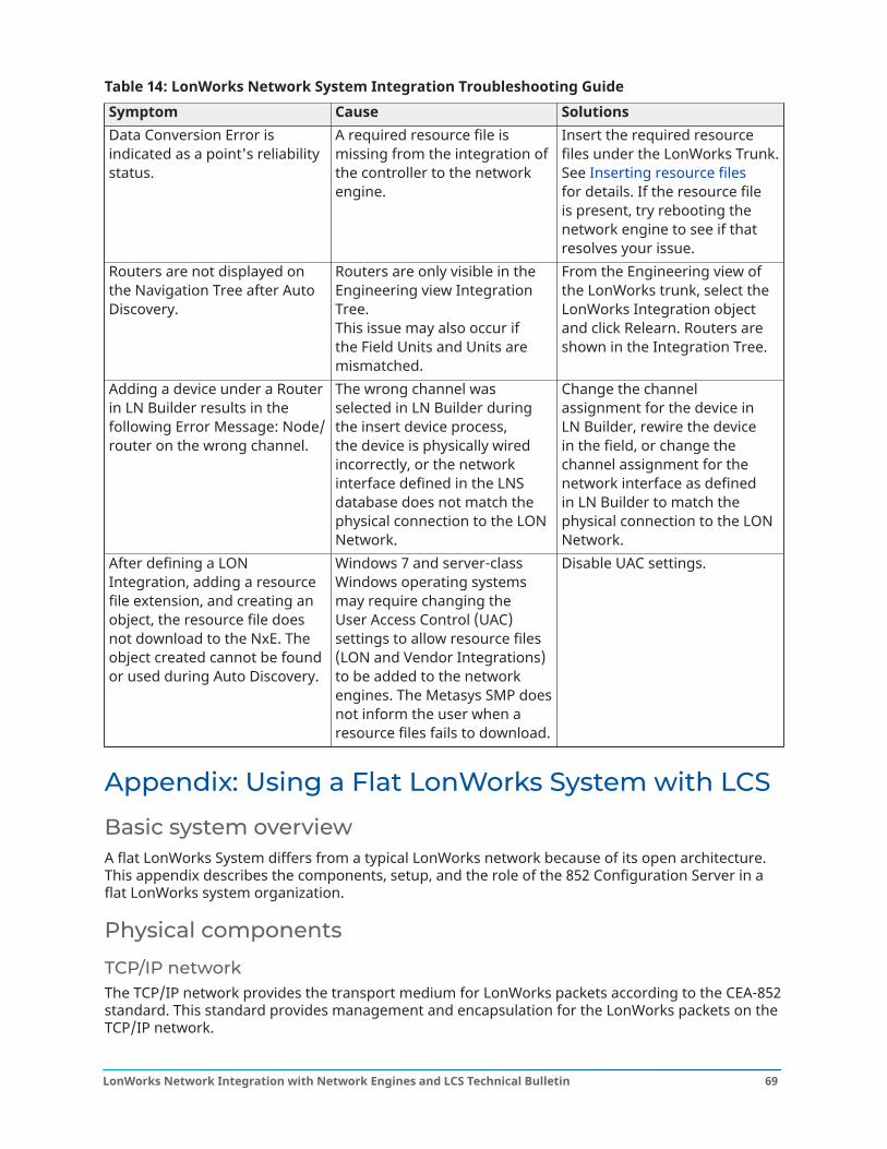
Table 14: LonWorks Network System Integration Troubleshooting GuideSymptom Cause SolutionsData Conversion Error isindicated as a point's reliabilitystatus.
A required resource file ismissing from the integration ofthe controller to the networkengine.
Insert the required resourcefiles under the LonWorks Trunk.See Inserting resource filesfor details. If the resource fileis present, try rebooting thenetwork engine to see if thatresolves your issue.
Routers are not displayed onthe Navigation Tree after AutoDiscovery.
Routers are only visible in theEngineering view IntegrationTree.This issue may also occur ifthe Field Units and Units aremismatched.
From the Engineering view ofthe LonWorks trunk, select theLonWorks Integration objectand click Relearn. Routers areshown in the Integration Tree.
Adding a device under a Routerin LN Builder results in thefollowing Error Message: Node/router on the wrong channel.
The wrong channel wasselected in LN Builder duringthe insert device process,the device is physically wiredincorrectly, or the networkinterface defined in the LNSdatabase does not match thephysical connection to the LONNetwork.
Change the channelassignment for the device inLN Builder, rewire the devicein the field, or change thechannel assignment for thenetwork interface as definedin LN Builder to match thephysical connection to the LONNetwork.
After defining a LONIntegration, adding a resourcefile extension, and creating anobject, the resource file doesnot download to the NxE. Theobject created cannot be foundor used during Auto Discovery.
Windows 7 and server-classWindows operating systemsmay require changing theUser Access Control (UAC)settings to allow resource files(LON and Vendor Integrations)to be added to the networkengines. The Metasys SMP doesnot inform the user when aresource files fails to download.
Disable UAC settings.
Appendix: Using a Flat LonWorks System with LCS
Basic system overviewA flat LonWorks System differs from a typical LonWorks network because of its open architecture.This appendix describes the components, setup, and the role of the 852 Configuration Server in aflat LonWorks system organization.
Physical components
TCP/IP networkThe TCP/IP network provides the transport medium for LonWorks packets according to the CEA-852standard. This standard provides management and encapsulation for the LonWorks packets on theTCP/IP network.
69LonWorks Network Integration with Network Engines and LCS Technical Bulletin
A site may have a single TCP/IP network, but multiple CEA-852 channels may be configured withinthat TCP/IP network.
LCS85 control serverThe LCS85 Control Server is a server-based machine that supervises many LonWorks fieldcontrollers through a CEA-852 Configuration Server.
LNS computerThe LNS computer runs a LonWorks network management tool such as LN Builder or LonMaker.LonWorks Network Services (LNS) is the underlying software that performs the actual LonWorksnetwork management tasks, such as assigning LonWorks addresses, binding, running data queries,and so on. These tools provide a user-friendly interface that directs commands down to the LNScomputer to perform actual network operations. The LNS computer can either be a laptop, which isonly connected to the network temporarily (when changes to the system are made), or it can be adedicated computer always attached to the network.
LonWorks IP routersLonWorks IP routers allow EIA-709 (LonWorks) packets to travel to and from the TCP/IP network.They are also true LonWorks routers because they must be configured by a LonWorks networkmanagement tool to function on the LonWorks network.
Note: If you use an IP852 router that is not manufactured by Echelon Corporation, Loytec, orAdept Systems, it might not be compatible with the LCS85. Refer to the LonWorks Control Server(LCS) 85 Product Bulletin (LIT-12011549) for a complete list of supported CEA-852 routers.
Loytec™ L-IP routerThe L-IP router is a combination device. It is a LonWorks IP router that can also serve as theCEA-852 Configuration Server.
Echelon® i.LON® 600 routerThe Echelon Ii.LON 600 is a LonWorks IP router for purposes of an LCS85-based system. Thepreviously released I.LON 1000 is a LonWorks IP router, but it uses an Echelon proprietary protocolthat is neither compatible with nor upgradeable to the CEA-852 standard.
Note: The Echelon i.LON 100e3 and i.LON SmartServer are fully compatible.
Logical components
CEA-852 standardThe CEA-852 standard specifies a method for transporting LonWorks (EIA-709) packets over a TCP/IP network and managing the devices that exchange LonWorks packets. The CEA-852 packets travelacross the network as User Datagram Protocol (UDP) or TCP packets using unicast or multicastaddressing.
Note: Not all devices support multicast addressing.
CEA-852 channelsCEA-852 channels form logical groups of nodes that interact on an IP network. The CEA-852channels are managed by a Configuration Server. Each LCS85 can only connect to a single CEA-852channel.
LonWorks Network Integration with Network Engines and LCS Technical Bulletin70
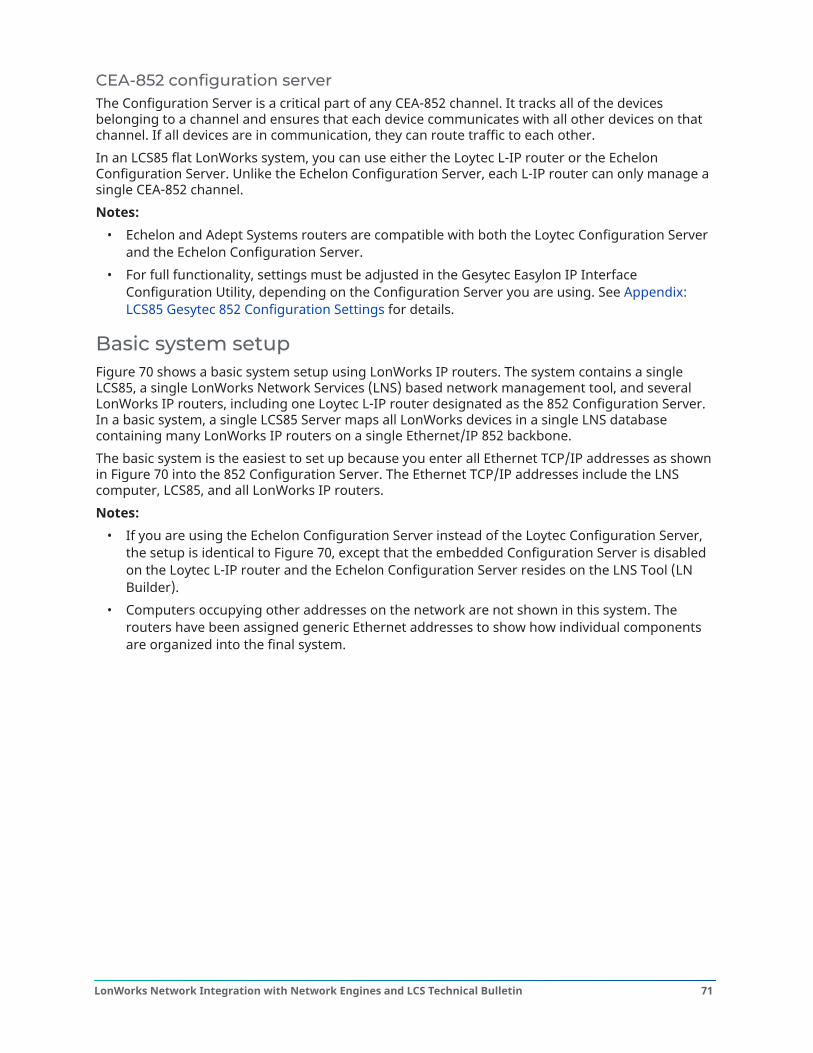
CEA-852 configuration serverThe Configuration Server is a critical part of any CEA-852 channel. It tracks all of the devicesbelonging to a channel and ensures that each device communicates with all other devices on thatchannel. If all devices are in communication, they can route traffic to each other.In an LCS85 flat LonWorks system, you can use either the Loytec L-IP router or the EchelonConfiguration Server. Unlike the Echelon Configuration Server, each L-IP router can only manage asingle CEA-852 channel.Notes:
• Echelon and Adept Systems routers are compatible with both the Loytec Configuration Serverand the Echelon Configuration Server.
• For full functionality, settings must be adjusted in the Gesytec Easylon IP InterfaceConfiguration Utility, depending on the Configuration Server you are using. See Appendix:LCS85 Gesytec 852 Configuration Settings for details.
Basic system setupFigure 70 shows a basic system setup using LonWorks IP routers. The system contains a singleLCS85, a single LonWorks Network Services (LNS) based network management tool, and severalLonWorks IP routers, including one Loytec L-IP router designated as the 852 Configuration Server.In a basic system, a single LCS85 Server maps all LonWorks devices in a single LNS databasecontaining many LonWorks IP routers on a single Ethernet/IP 852 backbone.The basic system is the easiest to set up because you enter all Ethernet TCP/IP addresses as shownin Figure 70 into the 852 Configuration Server. The Ethernet TCP/IP addresses include the LNScomputer, LCS85, and all LonWorks IP routers.Notes:
• If you are using the Echelon Configuration Server instead of the Loytec Configuration Server,the setup is identical to Figure 70, except that the embedded Configuration Server is disabledon the Loytec L-IP router and the Echelon Configuration Server resides on the LNS Tool (LNBuilder).
• Computers occupying other addresses on the network are not shown in this system. Therouters have been assigned generic Ethernet addresses to show how individual componentsare organized into the final system.
71LonWorks Network Integration with Network Engines and LCS Technical Bulletin
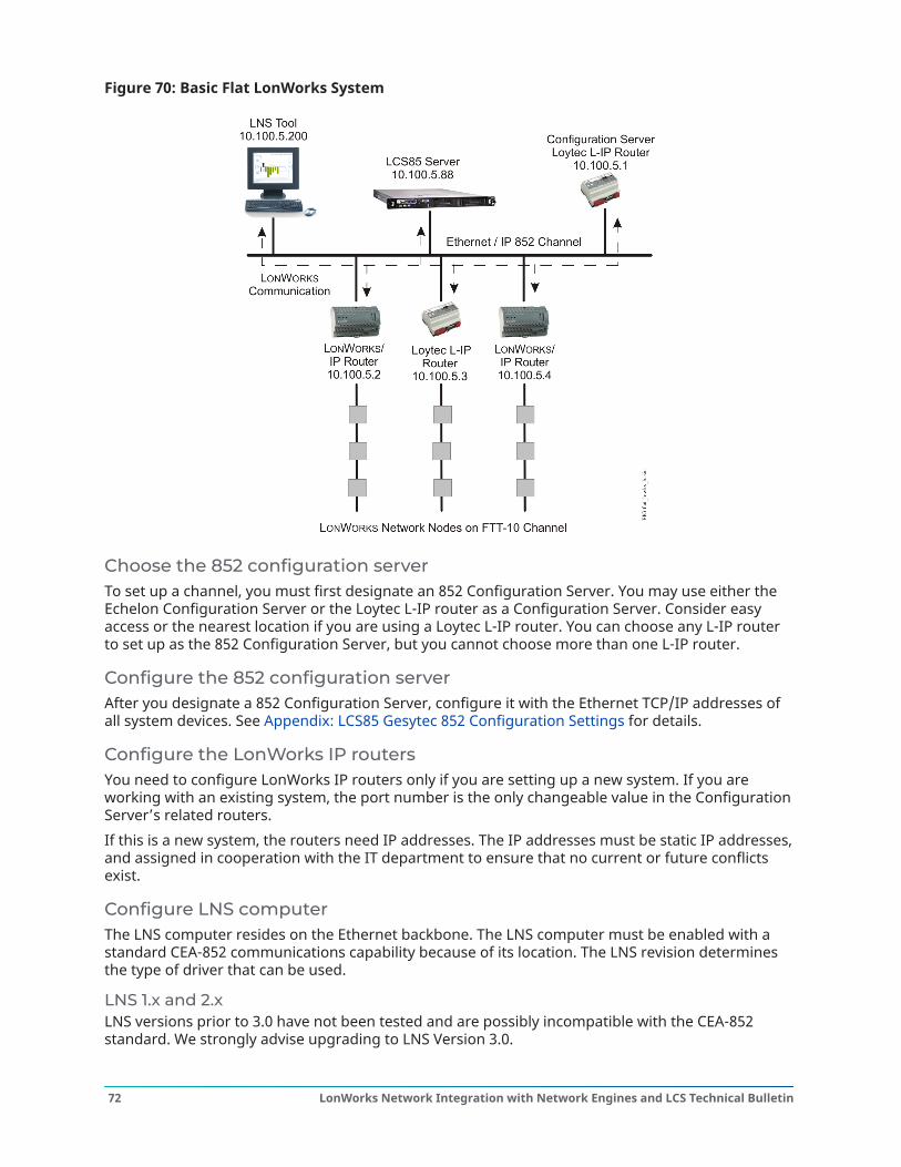
Figure 70: Basic Flat LonWorks System
Choose the 852 configuration serverTo set up a channel, you must first designate an 852 Configuration Server. You may use either theEchelon Configuration Server or the Loytec L-IP router as a Configuration Server. Consider easyaccess or the nearest location if you are using a Loytec L-IP router. You can choose any L-IP routerto set up as the 852 Configuration Server, but you cannot choose more than one L-IP router.
Configure the 852 configuration serverAfter you designate a 852 Configuration Server, configure it with the Ethernet TCP/IP addresses ofall system devices. See Appendix: LCS85 Gesytec 852 Configuration Settings for details.
Configure the LonWorks IP routersYou need to configure LonWorks IP routers only if you are setting up a new system. If you areworking with an existing system, the port number is the only changeable value in the ConfigurationServer’s related routers.If this is a new system, the routers need IP addresses. The IP addresses must be static IP addresses,and assigned in cooperation with the IT department to ensure that no current or future conflictsexist.
Configure LNS computerThe LNS computer resides on the Ethernet backbone. The LNS computer must be enabled with astandard CEA-852 communications capability because of its location. The LNS revision determinesthe type of driver that can be used.
LNS 1.x and 2.xLNS versions prior to 3.0 have not been tested and are possibly incompatible with the CEA-852standard. We strongly advise upgrading to LNS Version 3.0.
LonWorks Network Integration with Network Engines and LCS Technical Bulletin72
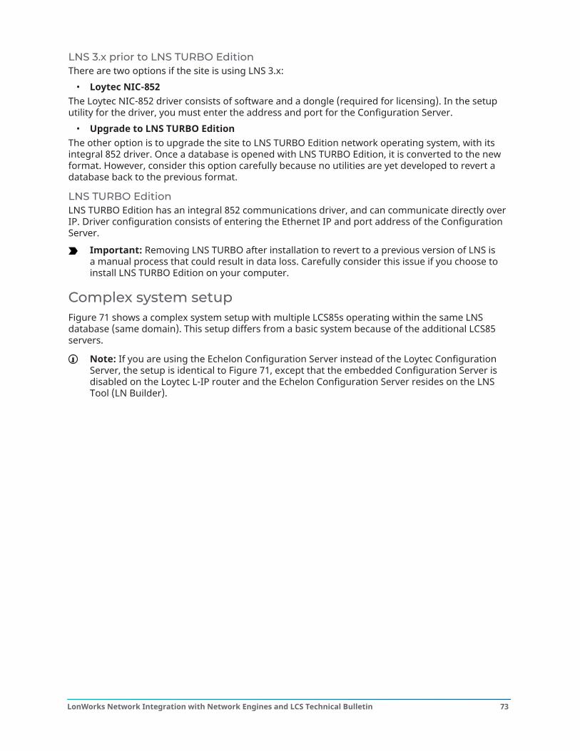
LNS 3.x prior to LNS TURBO EditionThere are two options if the site is using LNS 3.x:
• Loytec NIC-852The Loytec NIC-852 driver consists of software and a dongle (required for licensing). In the setuputility for the driver, you must enter the address and port for the Configuration Server.
• Upgrade to LNS TURBO EditionThe other option is to upgrade the site to LNS TURBO Edition network operating system, with itsintegral 852 driver. Once a database is opened with LNS TURBO Edition, it is converted to the newformat. However, consider this option carefully because no utilities are yet developed to revert adatabase back to the previous format.
LNS TURBO EditionLNS TURBO Edition has an integral 852 communications driver, and can communicate directly overIP. Driver configuration consists of entering the Ethernet IP and port address of the ConfigurationServer.
Important: Removing LNS TURBO after installation to revert to a previous version of LNS isa manual process that could result in data loss. Carefully consider this issue if you choose toinstall LNS TURBO Edition on your computer.
Complex system setupFigure 71 shows a complex system setup with multiple LCS85s operating within the same LNSdatabase (same domain). This setup differs from a basic system because of the additional LCS85servers.
Note: If you are using the Echelon Configuration Server instead of the Loytec ConfigurationServer, the setup is identical to Figure 71, except that the embedded Configuration Server isdisabled on the Loytec L-IP router and the Echelon Configuration Server resides on the LNSTool (LN Builder).
73LonWorks Network Integration with Network Engines and LCS Technical Bulletin
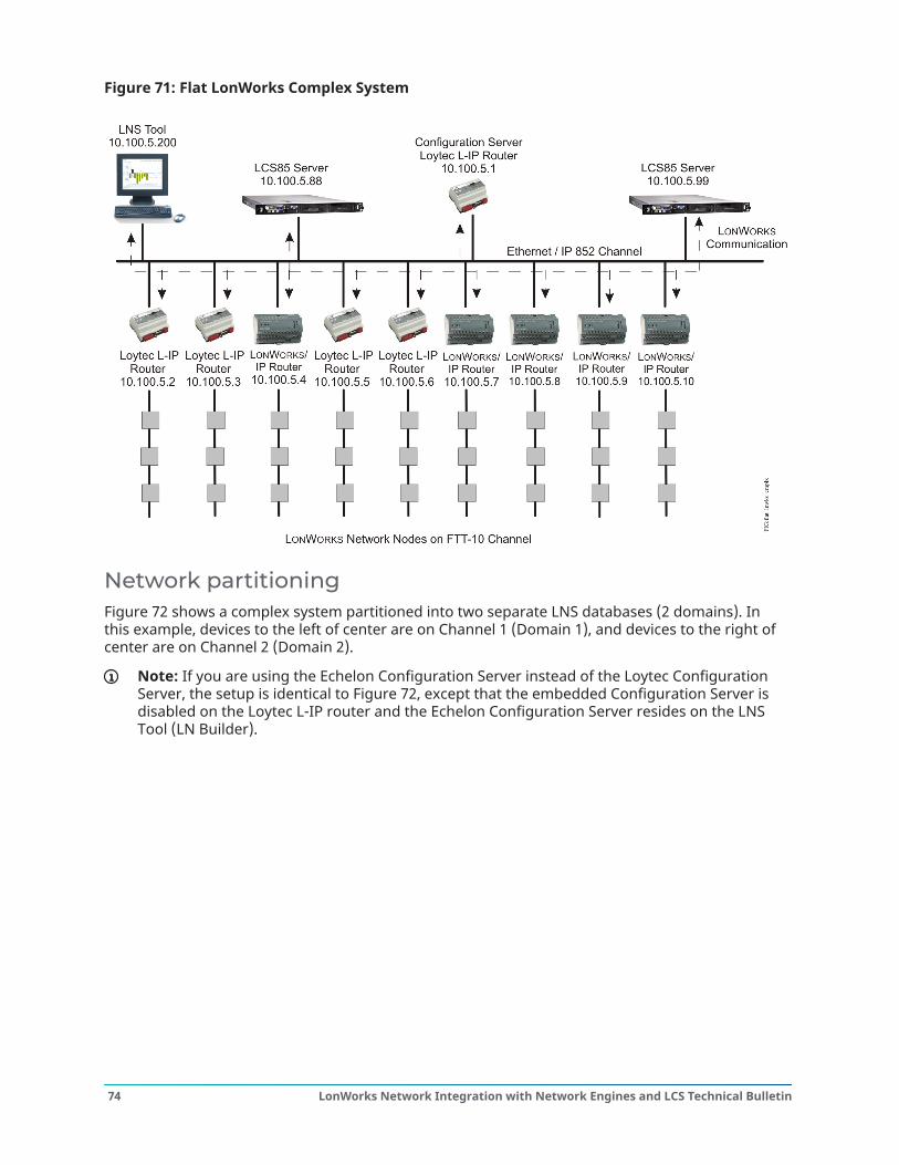
Figure 71: Flat LonWorks Complex System
Network partitioningFigure 72 shows a complex system partitioned into two separate LNS databases (2 domains). Inthis example, devices to the left of center are on Channel 1 (Domain 1), and devices to the right ofcenter are on Channel 2 (Domain 2).
Note: If you are using the Echelon Configuration Server instead of the Loytec ConfigurationServer, the setup is identical to Figure 72, except that the embedded Configuration Server isdisabled on the Loytec L-IP router and the Echelon Configuration Server resides on the LNSTool (LN Builder).
LonWorks Network Integration with Network Engines and LCS Technical Bulletin74
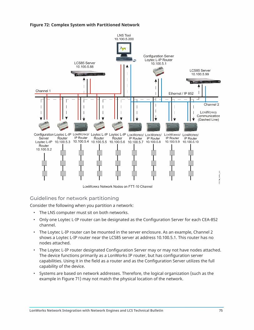
Figure 72: Complex System with Partitioned Network
Guidelines for network partitioningConsider the following when you partition a network:
• The LNS computer must sit on both networks.• Only one Loytec L-IP router can be designated as the Configuration Server for each CEA-852
channel.• The Loytec L-IP router can be mounted in the server enclosure. As an example, Channel 2
shows a Loytec L-IP router near the LCS85 server at address 10.100.5.1. This router has nonodes attached.
• The Loytec L-IP router designated Configuration Server may or may not have nodes attached.The device functions primarily as a LonWorks IP router, but has configuration servercapabilities. Using it in the field as a router and as the Configuration Server utilizes the fullcapability of the device.
• Systems are based on network addresses. Therefore, the logical organization (such as theexample in Figure 71) may not match the physical location of the network.
75LonWorks Network Integration with Network Engines and LCS Technical Bulletin
• The communication in a partitioned system is divided. In the Figure 71 example, the left LCS85(at address 10.100.5.88) communicates only with Ethernet routers 10.100.5.2, 10.100.5.3,10.100.5.4, 10.100.5.5, and 10.100.5.6. The right LCS85 communicates only with Ethernetrouters 10.100.5.1, 10.100.5.7, 10.100.5.8, 10.100.5.9, and 10.100.5.10. Binding and other datasharing cannot occur between these two systems. Any data sharing between the two groupscan only be done with the Metasys system through an Application and Data Server (ADS),Extended Application and Data Server (ADX), or Open Data Server (ODS).
Basic partitioned system setup
Choose the 852 configuration serverOn each system, you may use either the Echelon Configuration Server or designate one of theLoytec L-IP routers as the Configuration Server. For Channel 1, consider easy access or the nearestlocation if you are using a Loytec L-IP router.
Configure the 852 configuration serversAfter the Configuration Servers have been designated, each must be configured with the Ethernetaddresses of the devices belonging to its own 852 channel. See Appendix: LCS85 Gesytec 852Configuration Settings for details.
Configure the channelsThis partitioned system example includes two channels. Table 15 provides the IP addresses of alldevices on Optional: Channel 1. Table 16 provides the IP addresses of all devices on Channel 2.
Note: If you are using the Echelon Configuration Server instead of the Loytec ConfigurationServer, the channel configuration is identical to what is shown in Table 15 and Table 16, exceptthat the embedded Configuration Server is disabled on the Loytec L-IP router. Additionally, theEchelon Configuration Server resides on the LNS Tool (LN Builder) and is configured to handletwo separate LNS networks. The defined Configuration Server uses the same IP address with aunique port number in each instance to segregate the separate LNS networks.
Table 15: Channel 1 IP AddressesIP Address Device10.100.5.2 Loytec L-IP Router Configuration Server10.100.5.3 Loytec L-IP Router10.100.5.4 LonWorks Ethernet Router10.100.5.5 Loytec L-IP Router10.100.5.6 Loytec L-IP Router10.100.5.88 LCS85 Server10.100.5.200 LNS Computer
Table 16: Channel 2 IP AddressesIP Address Device10.100.5.1 Loytec L-IP Router Configuration Server10.100.5.7 LonWorks Ethernet Router10.100.5.8 LonWorks Ethernet Router10.100.5.9 LonWorks Ethernet Router10.100.5.10 LonWorks Ethernet Router
LonWorks Network Integration with Network Engines and LCS Technical Bulletin76
Table 16: Channel 2 IP AddressesIP Address Device10.100.5.99 LCS Server10.100.5.200 LNS Computer
Configure the LNS computerThe LNS computer has particular requirements for configuration during setup. Setup must becarefully considered, as each configuration option has its own effects on the system. See the Basicsystem overview section for information on CEA-852 driver issues.Setting up two LNS Computers is the equivalent to having two basic systems. Each LonWorkssystem is independent and set up separately. Both systems are simple, but the complete setuprequires more hardware and software.
Complex partitioned system setupAbout this task: This system comprises a single large LNS database containing all nodes in the system with multipleLCS85 servers. The LCS85 servers are segregated to communicate to different devices within thesame network. Segregation is based on designating complete FTT-10 channels to each LCS85. Youmanually partition the system ensuring only specific LonWorks IP routers (or specific nodes) aremapped to the LCS85. No device can be mapped to both systems.
This system closely meets flat LonWorks system specifications and is still considered flat becauseany node can be bound to any other node in the system. The purpose of LCS85 server segregationis to break up the network into manageable pieces for incorporation into a Metasys system.
Partitioning a network is a way to manage large systems, but does require some caution. Considerthe following issues when you partition a large system:
1. Partition the system carefully.Cleanly divide the system to provide easily understood system organization. Clustering alldevices under a single router is one method to clearly partition the system. Keeping each partof the system isolated prevents numerous smaller problems.
2. Consider command interference.Commands can interfere or clash with each other if two different LCS85 servers are com-manding the same point in the field or if the same point is mapped to multiple objects. Whencommands clash with one another, the device carries out the last issued command. Systemsthat have this problem behave erratically.
3. Isolate devices to one router and one server.When two LCS85 servers are communicating, each one checks message error rates (mes-sages unsuccessfully communicated). The error rate rapidly increases if multiple units startcommunicating down to a single router because the router can only handle a certain amountof traffic on the FTT-10 channel. As traffic increases, error rates increase and may overloadthe server. In response, all LCS85 servers reduce their communication rate to reduce theerror rates.In a situation where error rates are high, both LCS85 servers reduce their communication atthe same time and in the same manner because all machines use the same algorithm. Whenthe error rates decrease, they increase communication at the same time and same manner.If multiple units are competing for bandwidth on the same router, this rise and fall in trafficcontinues indefinitely. You can avoid this problem by keeping all devices under one routerisolated to one LCS85 server.
77LonWorks Network Integration with Network Engines and LCS Technical Bulletin
Appendix: LCS85 Gesytec 852 ConfigurationSettings
IntroductionThe LonWorks® Control Server (LCS) 85 is certified for use with either the Echelon® ConfigurationServer or the Loytec Configuration Server. The Gesytec Easylon IP Interface router resides on theLCS85 and requires different settings depending on which configuration server the LCS85 uses.Other configuration servers may work with the LCS85, but are not supported by Johnson Controls.Follow the instructions in this appendix to ensure successful operation of your LCS85. To reviewcomplete configuration procedures for each configuration server:
• Click Help > Contents in the Echelon LonWorks/IP Configuration Serverwindow.• Go to www.loytec.com and download the L-IP User Manual.
Easylon IP interface configuration settingsTable 17 defines the Easylon IP Interface Configuration window settings.Go to Configuring the LCS85 for use with the Loytec configuration server or Configuring the LCS85for use with the Echelon configuration server, depending on the configuration server you are using,and follow all directions in that section. See Table 17 as necessary as you configure the LCS85.Table 17: IP Interface Field DefinitionsOption DefinitionDevice Name User-defined name that identifies the device.
Note: The Loytec L-IP embedded configuration server updates themembers list using this name.
Config Server Address Address of the Configuration Server. Must be user configured.Config Server Port Port used by the Configuration Server. Must match what is defined in
the IP-852 Configuration Server. The default value is 1629 but may bechanged.
852 Interface Address IP Address of the LCS which must be selected from the pulldownmenu. The same address must be entered in the IP-852Configuration Server members list.
852 Interface Port Port used by the 852 Interface. Must match what is defined in theIP-852 Configuration Server members list. The default is 1628 butmay be changed.
RNI Interface Port Port used by the installed Remote Network Interface. The default is49852 and should not be changed.
Multicast Enables Multicast support to deliver one packet to a group of IPhosts. The default is unchecked.
Multicast Address If the Multicast option is selected, this IP address is used for themulticast group.
Multicast Port If the Multicast option is selected, this port is used for the multicastgroup.
Enable Soft License This option must be checked to use a software license.
LonWorks Network Integration with Network Engines and LCS Technical Bulletin78
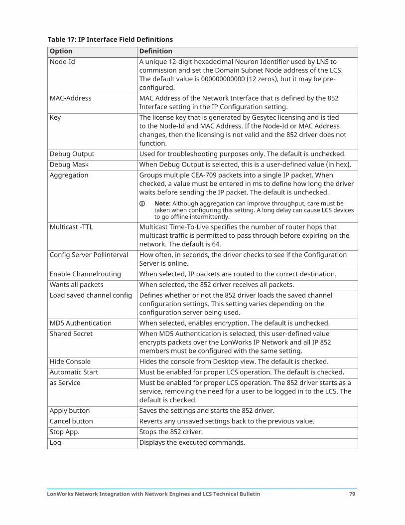
Table 17: IP Interface Field DefinitionsOption DefinitionNode-Id A unique 12-digit hexadecimal Neuron Identifier used by LNS to
commission and set the Domain Subnet Node address of the LCS.The default value is 000000000000 (12 zeros), but it may be pre-configured.
MAC-Address MAC Address of the Network Interface that is defined by the 852Interface setting in the IP Configuration setting.
Key The license key that is generated by Gesytec licensing and is tiedto the Node-Id and MAC Address. If the Node-Id or MAC Addresschanges, then the licensing is not valid and the 852 driver does notfunction.
Debug Output Used for troubleshooting purposes only. The default is unchecked.Debug Mask When Debug Output is selected, this is a user-defined value (in hex).Aggregation Groups multiple CEA-709 packets into a single IP packet. When
checked, a value must be entered in ms to define how long the driverwaits before sending the IP packet. The default is unchecked.
Note: Although aggregation can improve throughput, care must betaken when configuring this setting. A long delay can cause LCS devicesto go offline intermittently.
Multicast -TTL Multicast Time-To-Live specifies the number of router hops thatmulticast traffic is permitted to pass through before expiring on thenetwork. The default is 64.
Config Server Pollinterval How often, in seconds, the driver checks to see if the ConfigurationServer is online.
Enable Channelrouting When selected, IP packets are routed to the correct destination.Wants all packets When selected, the 852 driver receives all packets.Load saved channel config Defines whether or not the 852 driver loads the saved channel
configuration settings. This setting varies depending on theconfiguration server being used.
MD5 Authentication When selected, enables encryption. The default is unchecked.Shared Secret When MD5 Authentication is selected, this user-defined value
encrypts packets over the LonWorks IP Network and all IP 852members must be configured with the same setting.
Hide Console Hides the console from Desktop view. The default is checked.Automatic Start Must be enabled for proper LCS operation. The default is checked.as Service Must be enabled for proper LCS operation. The 852 driver starts as a
service, removing the need for a user to be logged in to the LCS. Thedefault is checked.
Apply button Saves the settings and starts the 852 driver.Cancel button Reverts any unsaved settings back to the previous value.Stop App. Stops the 852 driver.Log Displays the executed commands.
79LonWorks Network Integration with Network Engines and LCS Technical Bulletin
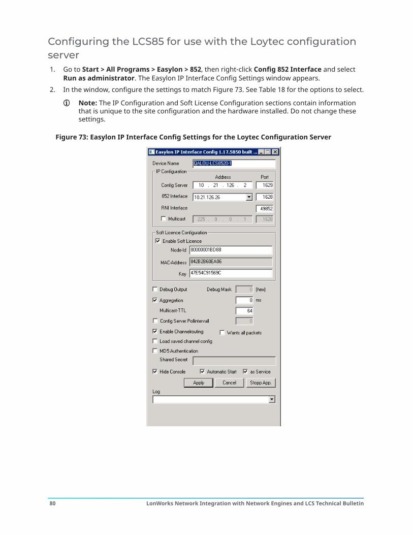
Configuring the LCS85 for use with the Loytec configurationserver1. Go to Start > All Programs > Easylon > 852, then right-click Config 852 Interface and select
Run as administrator. The Easylon IP Interface Config Settings window appears.2. In the window, configure the settings to match Figure 73. See Table 18 for the options to select.
Note: The IP Configuration and Soft License Configuration sections contain informationthat is unique to the site configuration and the hardware installed. Do not change thesesettings.
Figure 73: Easylon IP Interface Config Settings for the Loytec Configuration Server
LonWorks Network Integration with Network Engines and LCS Technical Bulletin80
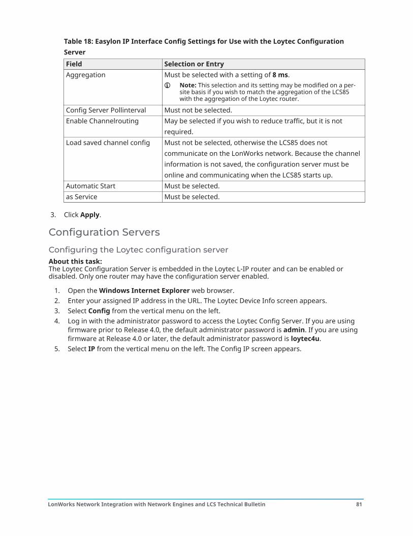
Table 18: Easylon IP Interface Config Settings for Use with the Loytec ConfigurationServerField Selection or EntryAggregation Must be selected with a setting of 8 ms.
Note: This selection and its setting may be modified on a per-site basis if you wish to match the aggregation of the LCS85with the aggregation of the Loytec router.
Config Server Pollinterval Must not be selected.Enable Channelrouting May be selected if you wish to reduce traffic, but it is not
required.Load saved channel config Must not be selected, otherwise the LCS85 does not
communicate on the LonWorks network. Because the channelinformation is not saved, the configuration server must beonline and communicating when the LCS85 starts up.
Automatic Start Must be selected.as Service Must be selected.
3. Click Apply.
Configuration Servers
Configuring the Loytec configuration serverAbout this task: The Loytec Configuration Server is embedded in the Loytec L-IP router and can be enabled ordisabled. Only one router may have the configuration server enabled.
1. Open the Windows Internet Explorer web browser.2. Enter your assigned IP address in the URL. The Loytec Device Info screen appears.3. Select Config from the vertical menu on the left.4. Log in with the administrator password to access the Loytec Config Server. If you are using
firmware prior to Release 4.0, the default administrator password is admin. If you are usingfirmware at Release 4.0 or later, the default administrator password is loytec4u.
5. Select IP from the vertical menu on the left. The Config IP screen appears.
81LonWorks Network Integration with Network Engines and LCS Technical Bulletin
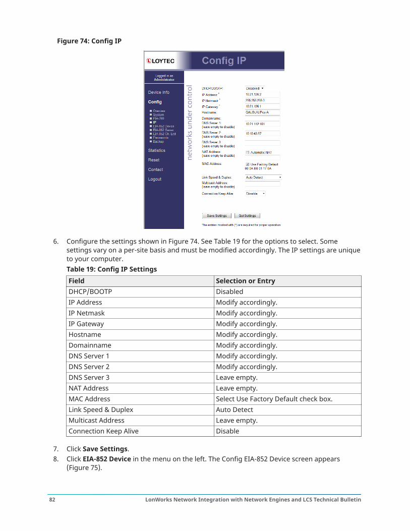
Figure 74: Config IP
6. Configure the settings shown in Figure 74. See Table 19 for the options to select. Somesettings vary on a per-site basis and must be modified accordingly. The IP settings are uniqueto your computer.Table 19: Config IP SettingsField Selection or EntryDHCP/BOOTP DisabledIP Address Modify accordingly.IP Netmask Modify accordingly.IP Gateway Modify accordingly.Hostname Modify accordingly.Domainname Modify accordingly.DNS Server 1 Modify accordingly.DNS Server 2 Modify accordingly.DNS Server 3 Leave empty.NAT Address Leave empty.MAC Address Select Use Factory Default check box.Link Speed & Duplex Auto DetectMulticast Address Leave empty.Connection Keep Alive Disable
7. Click Save Settings.8. Click EIA-852 Device in the menu on the left. The Config EIA-852 Device screen appears
(Figure 75).
LonWorks Network Integration with Network Engines and LCS Technical Bulletin82
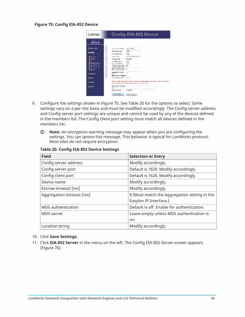
Figure 75: Config EIA-852 Device
9. Configure the settings shown in Figure 75. See Table 20 for the options to select. Somesettings vary on a per-site basis and must be modified accordingly. The Config server addressand Config server port settings are unique and cannot be used by any of the devices definedin the members list. The Config client port setting must match all devices defined in themembers list.
Note: An encryption warning message may appear when you are configuring thesettings. You can ignore this message. This behavior is typical for LonWorks protocol.Most sites do not require encryption.
Table 20: Config EIA-852 Device SettingsField Selection or EntryConfig server address Modify accordingly.Config server port Default is 1629. Modify accordingly.Config client port Default is 1628. Modify accordingly.Device name Modify accordingly.Escrow timeout [ms] Modify accordingly.Aggregation timeout [ms] 8 (Must match the Aggregation setting in the
Easylon IP Interface.)MD5 authentication Default is off. Enable for authentication.MD5 secret Leave empty unless MD5 authentication is
on.Location string Modify accordingly.
10. Click Save Settings.11. Click EIA-852 Server in the menu on the left. The Config EIA-852 Server screen appears
(Figure 76).
83LonWorks Network Integration with Network Engines and LCS Technical Bulletin
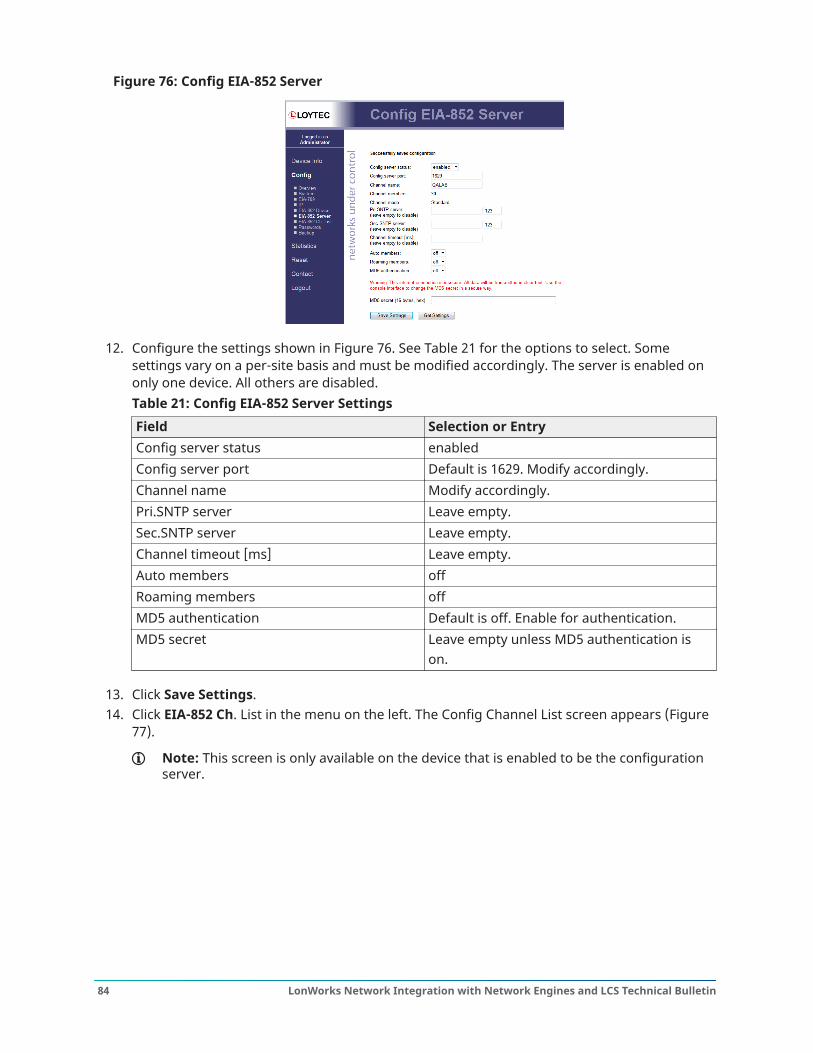
Figure 76: Config EIA-852 Server
12. Configure the settings shown in Figure 76. See Table 21 for the options to select. Somesettings vary on a per-site basis and must be modified accordingly. The server is enabled ononly one device. All others are disabled.Table 21: Config EIA-852 Server SettingsField Selection or EntryConfig server status enabledConfig server port Default is 1629. Modify accordingly.Channel name Modify accordingly.Pri.SNTP server Leave empty.Sec.SNTP server Leave empty.Channel timeout [ms] Leave empty.Auto members offRoaming members offMD5 authentication Default is off. Enable for authentication.MD5 secret Leave empty unless MD5 authentication is
on.
13. Click Save Settings.14. Click EIA-852 Ch. List in the menu on the left. The Config Channel List screen appears (Figure
77).
Note: This screen is only available on the device that is enabled to be the configurationserver.
LonWorks Network Integration with Network Engines and LCS Technical Bulletin84
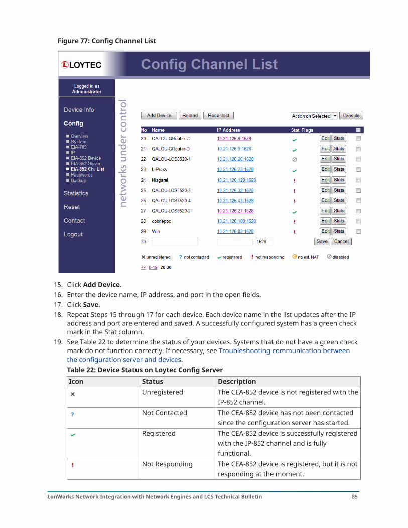
Figure 77: Config Channel List
15. Click Add Device.16. Enter the device name, IP address, and port in the open fields.17. Click Save.18. Repeat Steps 15 through 17 for each device. Each device name in the list updates after the IP
address and port are entered and saved. A successfully configured system has a green checkmark in the Stat column.
19. See Table 22 to determine the status of your devices. Systems that do not have a green checkmark do not function correctly. If necessary, see Troubleshooting communication betweenthe configuration server and devices.Table 22: Device Status on Loytec Config ServerIcon Status Description
Unregistered The CEA-852 device is not registered with theIP-852 channel.
Not Contacted The CEA-852 device has not been contactedsince the configuration server has started.
Registered The CEA-852 device is successfully registeredwith the IP-852 channel and is fullyfunctional.
Not Responding The CEA-852 device is registered, but it is notresponding at the moment.
85LonWorks Network Integration with Network Engines and LCS Technical Bulletin
Table 22: Device Status on Loytec Config ServerIcon Status Description
No Extended NAT The CEA-852 device does not support theextended NAT mode. This device is disabled.
Disabled The CEA-852 device is disabled, or rejected,on the channel.
20. When the configuration is complete, go to Configuring LonWorks interfaces and complete allsteps in that section.
Configuring the Echelon configuration serverAbout this task:
Note: Most installations that use the Echelon Config Server also use an LNS networkmanagement tool on the same computer.
1. Go to Start > All Programs > Echelon IP-852 Configuration Server > IP-852 ConfigurationServer. The Echelon LonWorks/IP Configuration Server window opens.
2. Select Channel > New Channel to create a new channel named Configuration Server.
Note: You can rename the channel by clicking the channel, then selecting Channel >Rename Channel in the menu.
3. Right-click Configuration Server and select Channel Properties. Ensure the channelproperties match those in Figure 81. The Configuration Server port is unique and is not usedby any of the devices in the list. The default port is 1629.
4. Select Channel > New Device.Notes:
- You can rename the device by clicking New Device, then selecting Device > RenameDevice in the menu. (All the devices in Figure 78 have been renamed.)
- If the config server resides on the same computer as the device, all device statusesupdate immediately. If the config server and the device reside on different computers,the status of the added device may not update until you select Update Members.
5. Right-click the new device and select Device Properties. Ensure the IP address is the sameand that the port is not the same as that in the Configuration Server. The default port is 1628for the device.
6. Repeat Steps 4 and 5 for each router that exists. The IP address and port must match what isdefined in the router.
7. Once all devices have been added, select Channel > Update Members. The configurationserver establishes communication with and updates the configuration of all the devices(Figure 78). If the update is successful, the device icon turns green, indicating normaloperation. Systems that are not green do not function correctly.
LonWorks Network Integration with Network Engines and LCS Technical Bulletin86
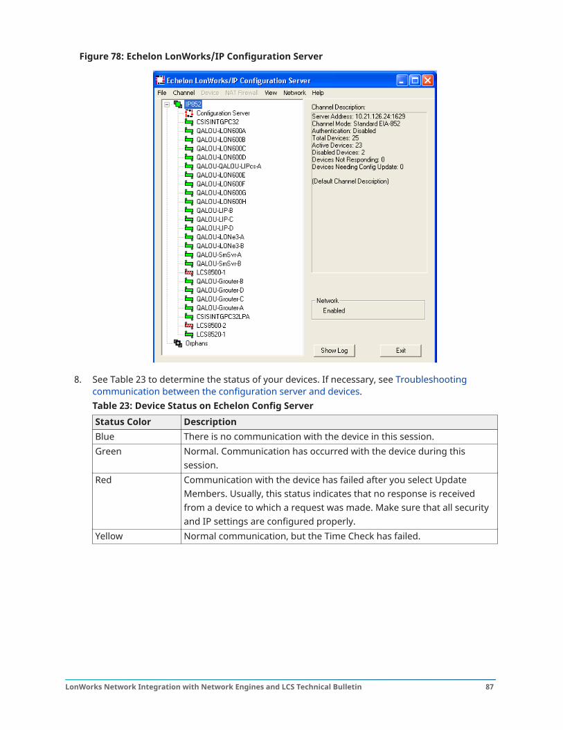
Figure 78: Echelon LonWorks/IP Configuration Server
8. See Table 23 to determine the status of your devices. If necessary, see Troubleshootingcommunication between the configuration server and devices.Table 23: Device Status on Echelon Config ServerStatus Color DescriptionBlue There is no communication with the device in this session.Green Normal. Communication has occurred with the device during this
session.Red Communication with the device has failed after you select Update
Members. Usually, this status indicates that no response is receivedfrom a device to which a request was made. Make sure that all securityand IP settings are configured properly.
Yellow Normal communication, but the Time Check has failed.
87LonWorks Network Integration with Network Engines and LCS Technical Bulletin
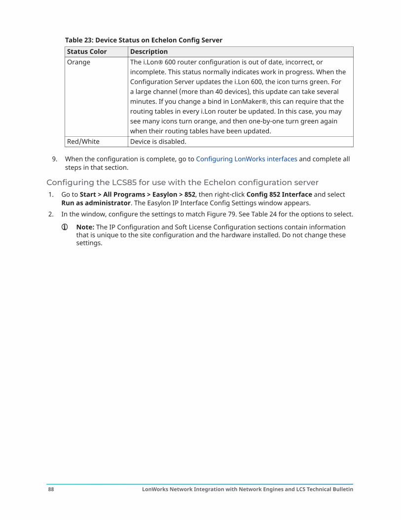
Table 23: Device Status on Echelon Config ServerStatus Color DescriptionOrange The i.Lon® 600 router configuration is out of date, incorrect, or
incomplete. This status normally indicates work in progress. When theConfiguration Server updates the i.Lon 600, the icon turns green. Fora large channel (more than 40 devices), this update can take severalminutes. If you change a bind in LonMaker®, this can require that therouting tables in every i.Lon router be updated. In this case, you maysee many icons turn orange, and then one-by-one turn green againwhen their routing tables have been updated.
Red/White Device is disabled.
9. When the configuration is complete, go to Configuring LonWorks interfaces and complete allsteps in that section.
Configuring the LCS85 for use with the Echelon configuration server1. Go to Start > All Programs > Easylon > 852, then right-click Config 852 Interface and select
Run as administrator. The Easylon IP Interface Config Settings window appears.2. In the window, configure the settings to match Figure 79. See Table 24 for the options to select.
Note: The IP Configuration and Soft License Configuration sections contain informationthat is unique to the site configuration and the hardware installed. Do not change thesesettings.
LonWorks Network Integration with Network Engines and LCS Technical Bulletin88
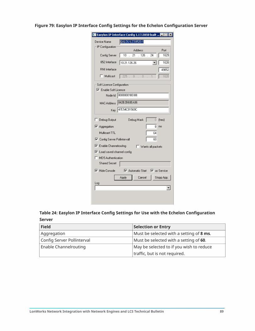
Figure 79: Easylon IP Interface Config Settings for the Echelon Configuration Server
Table 24: Easylon IP Interface Config Settings for Use with the Echelon ConfigurationServerField Selection or EntryAggregation Must be selected with a setting of 8 ms.Config Server Pollinterval Must be selected with a setting of 60.Enable Channelrouting May be selected to if you wish to reduce
traffic, but is not required.
89LonWorks Network Integration with Network Engines and LCS Technical Bulletin
Table 24: Easylon IP Interface Config Settings for Use with the Echelon ConfigurationServerField Selection or EntryLoad saved channel config Must be selected, otherwise the LCS85
does not communicate on the Lon networkat startup if the configuration server isnot running. The LCS85 must initiallycommunicate on the Lon network before thechannel configuration can be saved.
Automatic Start Must be selected.as Service Must be selected.
3. Click Apply.
Configuring LonWorks interfacesAbout this task: The LonWorks Interfaces (also referred to as the Open LDV Network Driver by Echelon) must beinstalled on a computer that is running LNBuilder using an IP-852 connection.
Important: Skip this section if LN Builder (or another LNS Network Management Tool) is notusing an IP-852 connection.
You must have a functioning configuration server set up before you configure LonWorks Interfaces.Follow all directions in Configuring the Loytec configuration server or Configuring the Echelonconfiguration server, depending on the configuration server you are using, before completing thesteps in this section.
1. Go to Control Panel > LonWorks Interfaces. The LonWorks Interfaces window opens.2. Select Interface > Add to see the interfaces you may add.
Note: Though not shown in Figure 80, the USB Interface automatically appears in the listwhen it is connected.
LonWorks Network Integration with Network Engines and LCS Technical Bulletin90
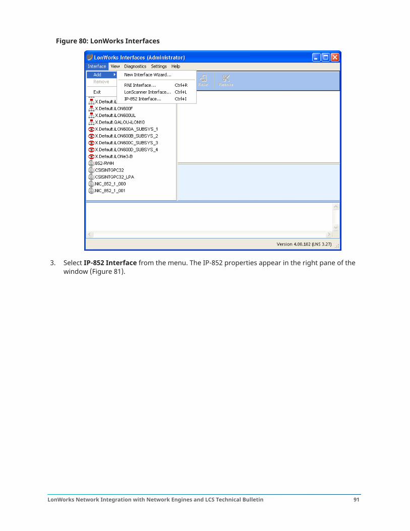
Figure 80: LonWorks Interfaces
3. Select IP-852 Interface from the menu. The IP-852 properties appear in the right pane of thewindow (Figure 81).
91LonWorks Network Integration with Network Engines and LCS Technical Bulletin
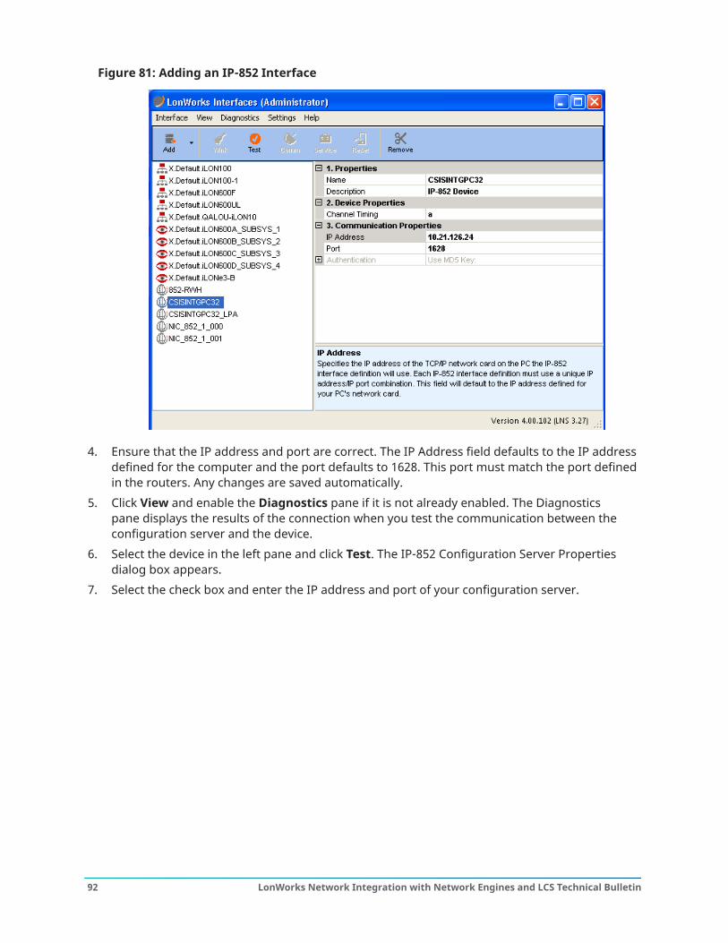
Figure 81: Adding an IP-852 Interface
4. Ensure that the IP address and port are correct. The IP Address field defaults to the IP addressdefined for the computer and the port defaults to 1628. This port must match the port definedin the routers. Any changes are saved automatically.
5. Click View and enable the Diagnostics pane if it is not already enabled. The Diagnosticspane displays the results of the connection when you test the communication between theconfiguration server and the device.
6. Select the device in the left pane and click Test. The IP-852 Configuration Server Propertiesdialog box appears.
7. Select the check box and enter the IP address and port of your configuration server.
LonWorks Network Integration with Network Engines and LCS Technical Bulletin92
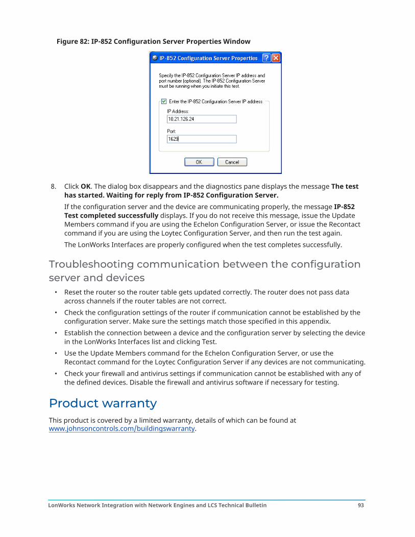
Figure 82: IP-852 Configuration Server Properties Window
8. Click OK. The dialog box disappears and the diagnostics pane displays the message The testhas started. Waiting for reply from IP-852 Configuration Server.If the configuration server and the device are communicating properly, the message IP-852Test completed successfully displays. If you do not receive this message, issue the UpdateMembers command if you are using the Echelon Configuration Server, or issue the Recontactcommand if you are using the Loytec Configuration Server, and then run the test again.The LonWorks Interfaces are properly configured when the test completes successfully.
Troubleshooting communication between the configurationserver and devices
• Reset the router so the router table gets updated correctly. The router does not pass dataacross channels if the router tables are not correct.
• Check the configuration settings of the router if communication cannot be established by theconfiguration server. Make sure the settings match those specified in this appendix.
• Establish the connection between a device and the configuration server by selecting the devicein the LonWorks Interfaces list and clicking Test.
• Use the Update Members command for the Echelon Configuration Server, or use theRecontact command for the Loytec Configuration Server if any devices are not communicating.
• Check your firewall and antivirus settings if communication cannot be established with any ofthe defined devices. Disable the firewall and antivirus software if necessary for testing.
Product warrantyThis product is covered by a limited warranty, details of which can be found atwww.johnsoncontrols.com/buildingswarranty.
93LonWorks Network Integration with Network Engines and LCS Technical Bulletin
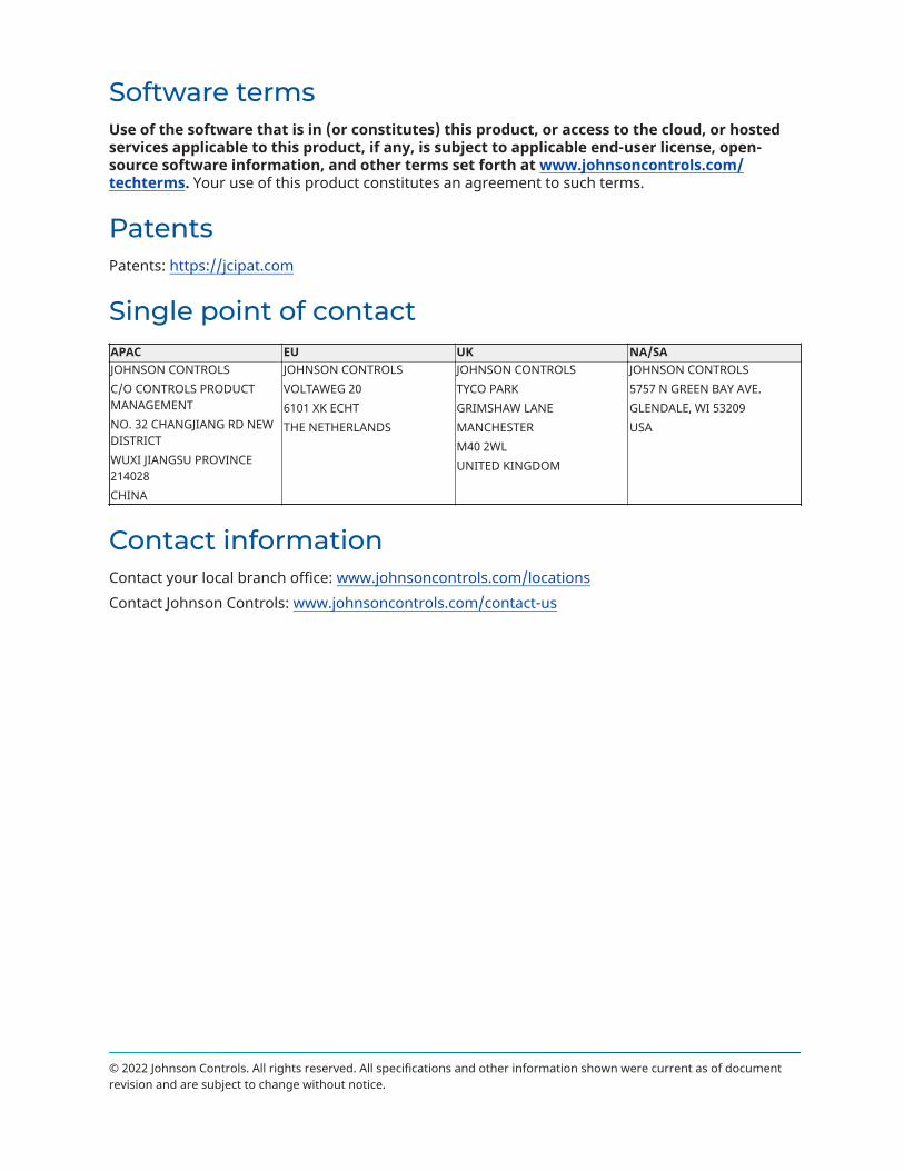
Software termsUse of the software that is in (or constitutes) this product, or access to the cloud, or hostedservices applicable to this product, if any, is subject to applicable end-user license, open-source software information, and other terms set forth at www.johnsoncontrols.com/techterms. Your use of this product constitutes an agreement to such terms.
PatentsPatents: https://jcipat.com
Single point of contactAPAC EU UK NA/SAJOHNSON CONTROLSC/O CONTROLS PRODUCTMANAGEMENTNO. 32 CHANGJIANG RD NEWDISTRICTWUXI JIANGSU PROVINCE214028CHINA
JOHNSON CONTROLSVOLTAWEG 206101 XK ECHTTHE NETHERLANDS
JOHNSON CONTROLSTYCO PARKGRIMSHAW LANEMANCHESTERM40 2WLUNITED KINGDOM
JOHNSON CONTROLS5757 N GREEN BAY AVE.GLENDALE, WI 53209USA
Contact informationContact your local branch office: www.johnsoncontrols.com/locationsContact Johnson Controls: www.johnsoncontrols.com/contact-us
© 2022 Johnson Controls. All rights reserved. All specifications and other information shown were current as of documentrevision and are subject to change without notice.
Related Documents