Lonsdale SkyGard Design Guide Introduction This Design Guide has been produced to assist specifiers and designers by illustrating typical installation details for sloped and vertical patent glazing. It is not exhaustive, but it does illustrate good practice for most applications and all details are in accordance with BS5516 for the design and installation of sloped and vertical patent glazing. Users of this guide must exercise all reasonable care to ensure that the details and products of Lonsdale Metal Company Limited are suitable for the intended purpose. If in doubt, ask us. Having decided to specify Lonsdale Patent Glazing, to save you valuable drafting time, CAD drawings of typical installation details are available on disk or from our website : www.roofglazing.co.uk If you require assistance please contact our Technical Department. Lonsdale Metal Company Limited, Millmead Industrial Centre, Mill Mead Road, London. N17 9QU Telephone : 020 8801 4221 Facsimile: 020 8801 1287 Contents Page Introduction 1 Guide to Selection of Glazing Bars 2 Cleaning and Maintenance 3 Recommended further reading 3 Maximum span between supports 4 Technical Summary 5 Typical Specification 6 Drawings & CAD Code Index 7 SkyGard CAD drawings 8 to 26 Research and Development 27 www.roofglazing.co.uk Page 1 PRINT OUT THIS DESIGN GUIDE FOR REFERENCE IF YOU WISH. CLICK THE Pages TAB TO SEE THUMBNAILS OF ALL THE PAGES IN THE PUBLICATION. TO PRINT OUT INDIVIDUAL PAGES, CLICK File, Print THEN CHECK Current page OR SELECT Pages RANGE AND CLICK OK. TO PRINT DRAWINGS TO THE SCALE INDICATED YOUR PRINT DRIVER MUST BE CAPABLE OF BEING SET AT 100%. LOOK IN YOUR PRINTER’S Properties FOR SETTINGS. CONTACT OUR TECHNICAL DEPARTMENT FOR FURTHER ADVICE.

Welcome message from author
This document is posted to help you gain knowledge. Please leave a comment to let me know what you think about it! Share it to your friends and learn new things together.
Transcript

Lonsdale SkyGard Design Guide
Introduction This Design Guide has been produced to assist specifiers and designers by illustrating typical installation details for sloped and vertical patent glazing. It is not exhaustive, but it does illustrate good practice for most applications and all details are in accordance with BS5516 for the design and installation of sloped and vertical patent glazing. Users of this guide must exercise all reasonable care to ensure that the details and products of Lonsdale Metal Company Limited are suitable for the intended purpose. If in doubt, ask us. Having decided to specify Lonsdale Patent Glazing, to save you valuable drafting time, CAD drawings of typical installation details are available on disk or from our website : www.roofglazing.co.uk If you require assistance please contact our Technical Department. Lonsdale Metal Company Limited, Millmead Industrial Centre, Mill Mead Road, London. N17 9QU Telephone : 020 8801 4221 Facsimile: 020 8801 1287 Contents
Page
Introduction
1
Guide to Selection of Glazing Bars
2
Cleaning and Maintenance
3
Recommended further reading
3
Maximum span between supports
4
Technical Summary
5
Typical Specification
6
Drawings & CAD Code Index
7
SkyGard CAD drawings
8 to 26
Research and Development
27
www.roofglazing.co.uk Page 1
PRINT OUT THIS DESIGN GUIDE FOR REFERENCE IF YOU WISH. CLICK THE Pages TAB TO SEE THUMBNAILS OF ALL THE PAGES IN THE PUBLICATION.
TO PRINT OUT INDIVIDUAL PAGES, CLICK File, Print THEN CHECK Current page OR SELECT Pages RANGE AND CLICK OK. TO PRINT DRAWINGS TO THE SCALE INDICATED YOUR PRINT DRIVER MUST BE CAPABLE OF BEING SET AT 100%. LOOK IN YOUR PRINTER’S
Properties FOR SETTINGS. CONTACT OUR TECHNICAL DEPARTMENT FOR FURTHER ADVICE.

Guide to the Selection of Glazing Bars Scope The data given indicates the maximum unsupported spans for the range of Lonsdale SkyGard Glazing Bars when subjected to the three combined loading conditions of 800, 1200 and 1800 N/ m². They are broadly defined in Table 1 alongside typical site locations for these loadings. Tables 2 and 3 respectively (page 4) give the spans for bars carrying single and double glazing; they cover different double pitch roof angles and vertical glazing. Standards The data has been calculated using the following Standards : BS6399:Part 3 British Standard loading for buildings Code of practice for imposed loads. BS5516:1991 Code of practice for the design and installation of patent glazing. BSCP3:Chapter V: Part 2:1972 Code of basic data for the design of buildings - wind loads. Loadings Combinations of wind and snow loadings, together with the self-weight of bars and glass, have been considered in determining the maximum bar spans. Surface and local wind pressure coefficients (the latter relating to the higher loaded areas on the roof edges and wall comers - see the shaded area of fig 1), are both taken into consideration. Likewise, the effects of uniform and asymmetric snow loading are also included. Fig1 Local high load areas (shaded) on the roof and wall glazing Location and Site Conditions Table 1
Maximum eaves height
Basic wind speed
Dynamic wind pressure
Basic snow loading
Combined wind & snow loading
Typical location
m m/s N/m² N/m² N/m² City centre
4.0 44 400 400 800
Outskirts of large city
5.0 46 650 550 1200
Open country
6.0 50 1250 550 1800
Page 2

Guide to the Selection of Glazing Bars - continued Limitations Tables 2 and 3 (page 4 are restricted to :
• Glazed walls and double pitched roofs of rectangular clad buildings of height / width ratios up to 6 : 1 and length / width ratios up to 4 :1.
• Two edge support of glass on bars spaced at 600mm. • Single glazing using 6mm polished or 7mm wired cast glass. • Hermetically sealed double glazed units, with 6mm thick float, toughened or
laminated glass in any combination. Failure Conditions The glazing bar spans given will not fail due to either excessive deflection or stressing of the components, in accordance with the above standards. Technical Support Care should be taken in applying the above data to different site locations, conditions, building size or roof types (including canopies ). In such instances, Lonsdale Metal Company will be pleased to give further advice, upon request. Cleaning and Maintenance Recommended procedures can be found on our website www.roofglazing.co.uk and in BS5516 - Code of practice for the design & installation of sloping and vertical patent glazing. In addition, if materials are coated with an architectural finish e.g. polyester powder paint, advice should be sought from the manufacturers / applicator of the process. Recommended further reading BS5516 - Code of practice for the design & installation of sloping and vertical patent glazing BS6399:Part 3 - Loading for buildings - Code of practice for imposed loads BS CP3 Chapter V Part 2 - Code of basic data for the design of buildings - Wind loads NBS Specification H10 Patent Glazing
Page 3

Guide to the Selection of Glazing Bars - continued Maximum span between supports (metres) NB: The overall bar length may exceed these values in order to provide an overhang at the eaves and/or ridge. Single Glazed Bars Table 2
Combined basic wind & snow loading
Angle of Glazing relevant to the horizontal
N/m²
Glazing Bar
15° 22.5° 30° 45° 60° Vertical SKY50 2.47 2.59 2.57 2.77 2.77 2.60 SKY65 3.19 3.08 3.05 3.36 3.45 3.35 SKY71 3.69 3.85 3.85 3.89 3.89 3.78
800
SKY76 4.09 4.24 4.23 4.30 4.30 4.18 SKY50 1.86 2.04 2.03 2.33 2.27 2.06 SKY65 2.45 2.68 2.67 2.89 2.92 2.71 SKY71 3.20 3.35 3.34 3.58 3.53 3.36
1200
SKY76 3.55 3.71 3.70 3.97 3.90 3.72 SKY50 1.28 1.39 1.39 1.59 1.57 1.47 SKY65 1.68 1.83 1.82 2.09 2.06 1.93
1800
SKY71 2.29 2.50 2.49 2.86 2.82 2.64
Double Glazed Bars Table 3
Combined basic wind & snow loading
Angle of Glazing relevant to the horizontal
N/m²
Glazing Bar
15° 22.5° 30° 45° 60° Vertical SKY50 - - - - - - SKY65 2.08 2.03 2.03 2.11 2.16 2.15 SKY71 2.64 2.58 2.58 2.69 2.75 2.75
800
SKY76 3.25 3.21 3.21 3.74 3.71 3.98 SKY50 - - - - - - SKY65 1.64 1.81 1.79 1.84 1.81 1.71 SKY71 2.09 2.31 2.29 2.34 2.30 2.18
1200
SKY76 2.90 3.05 3.04 3.27 3.18 2.96 SKY50 - - - - - - SKY65 1.08 1.19 1.18 1.36 1.33 1.21 SKY71 1.38 1.51 1.51 1.73 1.69 1.55
1800
SKY76 2.36 2.47 2.46 2.64 2.61 2.50
Page 4

Technical Summary Patent Glazing Bars Specification Glazing Bars, Cappings, Beads and Fittings are extruded aluminium alloy 6063-T6 to BS1474. Fasteners provided are either stainless steel to BS304515 Grade A2 or mild steel bright zinc plated. Gaskets are extruded Thermo Plastic Rubber quality 98625 to BS4255:Part1:1986 Grade C. Performance All systems are designed to conform with the requirements of BS5516 when installed within the manufacturers recommendations. A guide to maximum spans is given on page 4 of the Design Guide and should be referred to prior to planning an installation. Fixing Fixing to timber is directly through the channels at the top of the glazing bars with two No. 10 x 1.5 inch bright zinc plated wood screws and a sliding shoe with wood screws at the bottom end. Fixing to metal is with M8 Single Hole Fixing Shoes positively fixed at the top and sliding at the bottom end. Dissimilar metals should be isolated to avoid bi-metallic corrosion Appearance Materials are supplied Mill Finished as standard. A range of architectural finishes is available including polyester powder coating to BS6496 in standard RAL or BS colour ranges. Ventilation May be achieved either through GlazaTherm, our top hung roof ventilator, or by casement vents in vertical applications. Various factory fitted opening mechanisms are available including manual, pole or cord operated, electrical, thermostatic or smoke activated controls. Infill All popular specifications can be accommodated including 6 / 7mm Single Glazing, 24mm and 28mm Double Glazed Sealed Units or 10mm,16mm or 25mm Polycarbonate Sheeting. Other infills should be discussed with our technical department. Double Glazed combinations should feature a suitable "step" to the bottom edge to avoid thermal breaking. Building Regulations Please visit our website www.roofglazing.co.uk for guidance and compliance with the Regulations relating to fire, non-fragility, thermal and air-tightness performance.
Page 5

Typical Specification See www.roofglazing.co.uk for Quick Specifications which cover most popular typical applications or contact out Technical Support for advice. We recommend you consider the National Building Specification H10 Patent Glazing. If you do not have access to a copy they can be contacted at:- NBS Services, Mansion House Chambers, The Close, Tel : 0191 232 9594 Newcastle upon Tyne NE1 3RE Fax : 0191 232 5714 Typical Specification for Patent Glazing Bars NB: Italics show where you must insert the detail relevant to your project Patent Glazing:
To entrance canopy north elevation
Drawing Reference:
Drawing Numbers 123, 124, 125
Supporting Structure:
Timber at ridge, hip, intermediate and eves
Patent Glazing System:
To BS5516, and as specified in this section
Manufacture & Reference: Lonsdale Metal Company Limited, London N17 9QU Telephone: 020 8801 4221 Facsimile : 020 8801 1287 Reference SKYGARD SKY65
Type: Traditional “T” bar with continuous pressure beads and gaskets
Glazing Bar: Material Finish Colour Minimum film thickness Spacing: Slop: Bottom overhang lap:
Aluminium alloy 6063-T6 to BS1474 Polyester Powder Paint to BS6496 White M4A0001 40 microns Nominally 600mm glazing bar c/c 30 degrees 75mm
Pane/infilling material(s):
6.4mm clear laminate
Incorporated components:
None Please note : Whilst we are pleased to assist, the above example is given for guidance only. Responsibility remains with Specifiers to exercise all reasonable care ensuring our products are suitable for their requirements and correctly specified.
Page 6

Drawings and CAD Code Index SkyGard Drawing number CAD code
Description Page
SKY50Y SKY65Y SKY71Y SKY76Y EBARWING MFIXSHOE SKY11MY SKY11TY SKY12MY SKY12TY SKY13MY SKY13TY SKY14X 22Y SKY18MY SKY18TY SKY19MY SKY19TY SKY21Y SKY23MY SKY23TY SKY24MY SKY24TY SKY25MY SKY25TY SKY26X SKY27X SKY28X SKY29MY SKY31X SKY32MY SKY32TY
SKY50 profile SKY65 profile SKY71 profile SKY76 profile End bar wing Metal fixing shoe Top fixing to metal Top fixing to timber Eaves fixing to metal Eaves fixing to timber Valley gutter aluminium or steel Valley gutter detail lead lined to timber Parapet to brickwork Glass jointing Hip detail to metal Hip detail to timber Ridge detail to metal Ridge detail to timber Intermediate roof detail to timber/steel Tiered roof detail to metal Tiered roof detail to timber Vertical head fixing to steel Vertical head fixing to timber Vertical cill to metal Vertical cill to timber Vertical jamb to brickwork Internal corner to vertical External corner to vertical Vertical intermediate detail Verge Lead flashing to steel ridge / hip Lead flashing to timber ridge / hip
8 8 8 9 9 9 10 10 11 11 12 13 14 14 15 16 17 18 19 19 20 21 21 22 22 23 23 23 24 24 25 26
Page 7

SkyGard SkyGard is the latest development of the original Lonsdale glazing bars first introduced over fifty years ago. Maintaining all the benefits of traditional patent glazing. SkyGard utilises modem technology to beat all others in terms of weathering performance and value for money.
• Quick and easy to fit continuous pressure beads. • Traditional" T " bar appearance. • 6/7 mm single glazing or 24 mm double glazing – not thermally broken. • Economy without sacrifice to quality or performance. • No-nonsense easy to follow installation details.
SKY50 Profile CAD Code SKY50Y
SKY65 Profile CAD Code SKY65Y
Single Glazing only
Single Glazing Double Glazing
SKY71 Profile CAD Code SKY71Y
Single Glazing
Double Glazing
Scale of all profiles 1:1
Page 8

SkyGard SKY76 Profile CAD Code SKY76Y
Single Glazing
Double Glazing
Metal Fixing Shoe CAD Code MFIXSHOE
End Bar Wing CAD Code EBARWING
Fixing to metal supports is by single hole fixing shoe supplied with stainless steel M8 nut and bolt. Alternatively, fixing to RHS may be achieved by drilling and tapping into the metal supports using the fixing shoe and M6 machine set screws or suitable TEK screws.
End bar wing fits all sections and should be secured with No 8 self-tapping screws.
Scale of all profiles 1:1
Page 9

SkyGard Top fixing to metal CAD Code SKY11MY
Top fixing to timber CAD Code SKY11TY
Scale of views 1-2
Page 10
DIS-SIMILAR METALSDIS-SIMILAR METALS
BI-METALLIC CORROSION BETWEENBI-METALLIC CORROSION BETWEEN
SUITABLE ISOLATOR TO AVOIDSUITABLE ISOLATOR TO AVOID
SINGLE HOLE M8 x 25mm POSITIVESINGLE HOLE M8 x 25mm POSITIVE
TOP FIXING SHOE RIVETTED TO BARTOP FIXING SHOE RIVETTED TO BAR
LONSDALE SKYGARD SERIESLONSDALE SKYGARD SERIES
GLAZING BARGLAZING BAR
No.10 x 1 " GALVANIZEDNo.10 x 1 " GALVANIZED
TOP SUPPORTTOP SUPPORT
WOOD SCREW FIXINGWOOD SCREW FIXING
//11 22
BE NOTCHED OUT FOR LEAD FLASHINGBE NOTCHED OUT FOR LEAD FLASHING
IF REQUESTED, LONSDALE BARS MAY IF REQUESTED, LONSDALE BARS MAY
Application
Application

SkyGard Eaves fixing to metal CAD Code SKY12MY
Eaves fixing to timber CAD Code SKY12TY
Scale of views 1-2
Page 11
SLIDING BOTTOMSLIDING BOTTOM
SINGLE HOLE FIXING SHOESINGLE HOLE FIXING SHOE
LONSDALE SKYGARD SERIESLONSDALE SKYGARD SERIES
GLAZING BAR GLAZING BAR
AVOID BI-METALLIC CORROSIONAVOID BI-METALLIC CORROSION
SUITABLE ISOLATOR TOSUITABLE ISOLATOR TO
BETWEEN DIS-SIMILAR METALSBETWEEN DIS-SIMILAR METALS
BLACK PVC-U DRAUGHTBLACK PVC-U DRAUGHT
EXCLUDEREXCLUDER
LONSDALE SKYGARD SERIESLONSDALE SKYGARD SERIES
GLAZING BAR GLAZING BAR
LONSDALE END STOP LONSDALE END STOP
BOTTOM SUPPORTBOTTOM SUPPORT
GASKETGASKET
SLIDING FIXING SHOESLIDING FIXING SHOE
EXCLUDEREXCLUDERBLACK PVC-U DRAUGHT BLACK PVC-U DRAUGHT
Application
Application
SkyGard
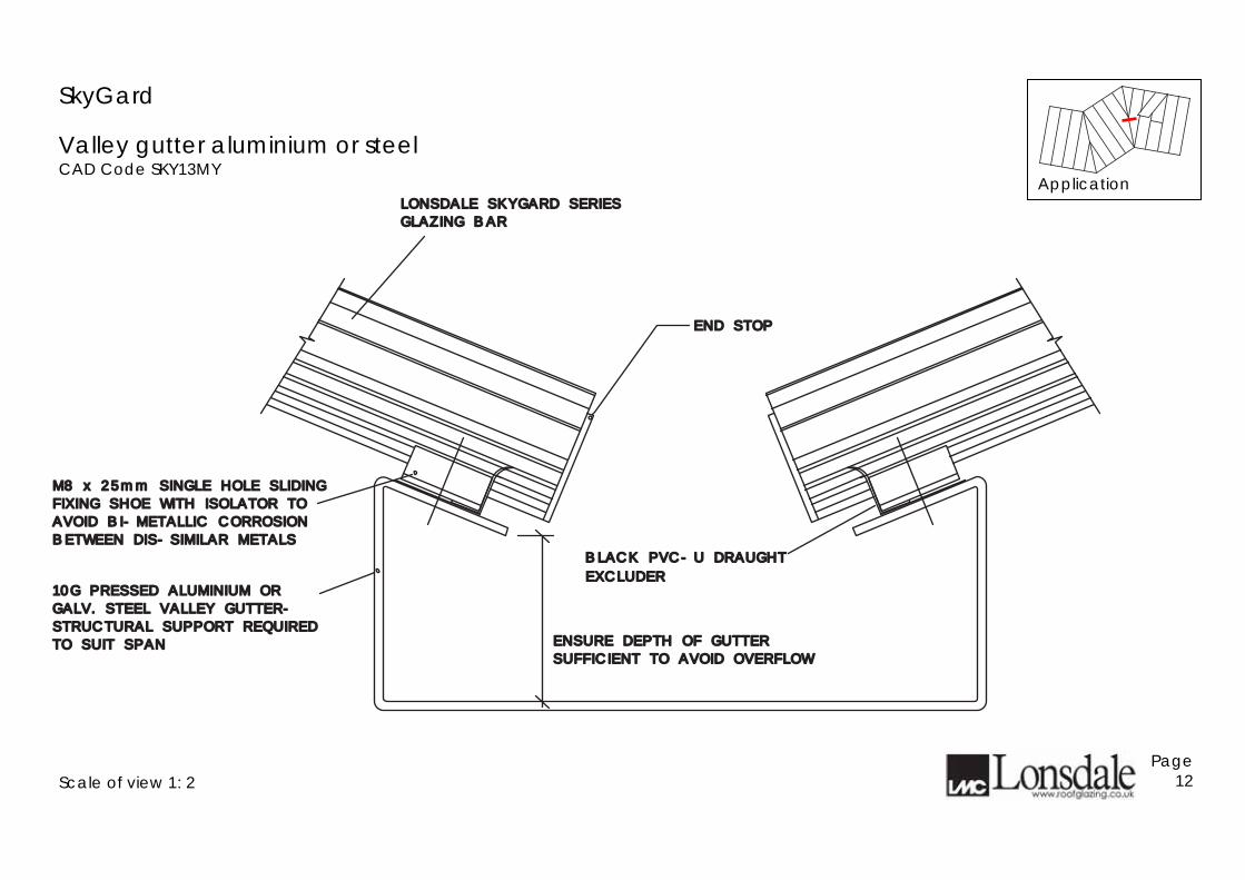
Valley gutter aluminium or steel CAD Code SKY13MY
Scale of view 1: 2
Page 12
END STOPEND STOP
LONSDALE SKYGARD SERIESLONSDALE SKYGARD SERIES
GLAZING BAR GLAZING BAR
M8 x 25mm SINGLE HOLE SLIDINGM8 x 25mm SINGLE HOLE SLIDING
FIXING SHOE WITH ISOLATOR TOFIXING SHOE WITH ISOLATOR TO
AVOID BI-METALLIC CORROSIONAVOID BI-METALLIC CORROSION
BETWEEN DIS-SIMILAR METALSBETWEEN DIS-SIMILAR METALS
ENSURE DEPTH OF GUTTERENSURE DEPTH OF GUTTER
SUFFICIENT TO AVOID OVERFLOWSUFFICIENT TO AVOID OVERFLOW
10G PRESSED ALUMINIUM OR10G PRESSED ALUMINIUM OR
GALV. STEEL VALLEY GUTTER-GALV. STEEL VALLEY GUTTER-
STRUCTURAL SUPPORT REQUIRED STRUCTURAL SUPPORT REQUIRED
TO SUIT SPANTO SUIT SPAN
EXCLUDEREXCLUDER
BLACK PVC-U DRAUGHT BLACK PVC-U DRAUGHT
Application

SkyGard
Valley gutter detail lead lined to timber CAD Code SKY13TY
Scale of view 1: 2
Page 13
END STOPEND STOP
LONSDALE SKYGARD SERIESLONSDALE SKYGARD SERIES
GLAZING BAR GLAZING BAR
GLAZING BAR FIXED TO TIMBERGLAZING BAR FIXED TO TIMBER
SLIDING FIXING SHOESLIDING FIXING SHOE
ENSURE DEPTH OF ENSURE DEPTH OF
GUTTER SUFFICIENT TO GUTTER SUFFICIENT TO TIMBER LEAD LINEDTIMBER LEAD LINED
VALLEY GUTTERVALLEY GUTTER PREVENT OVERFLOWPREVENT OVERFLOW
EXCLUDEREXCLUDER
BLACK PVC-U DRAUGHT BLACK PVC-U DRAUGHT
Application

SkyGard Parapet to brickwork CAD Code SKY14X
Glass jointing – Single glazing CAD Code 22Y
Scale of views 1-2
Page 14
LONSDALE SKYGARD SERIESLONSDALE SKYGARD SERIES
GLAZING BARGLAZING BAR
LEAD FLASHINGLEAD FLASHING
Application
Application SILICONE POINTINGSILICONE POINTING
AROUND GLASSAROUND GLASS
THERMALLY BROKEN H CAMETHERMALLY BROKEN H CAME SILICONE POINTINGSILICONE POINTING
AROUND GLASSAROUND GLASS

SkyGard
Hip detail to metal CAD Code SKY18MY – also see page 31 CAD Code SKY32MY
Scale of view 1: 2
Page 15
LONSDALE HIP CARRIER PACKEDLONSDALE HIP CARRIER PACKED
ACCORDINGLYACCORDINGLY
SUITABLE ISOLATOR TO AVOIDSUITABLE ISOLATOR TO AVOID
BI-METAL CORROSION BETWEENBI-METAL CORROSION BETWEEN
DIS-SIMILAR METALSDIS-SIMILAR METALS
NOTCHED FOR FLASHINGNOTCHED FOR FLASHING
GLAZING BAR STALK GLAZING BAR STALK
SCREW FIXED TO HIP CARRIERSCREW FIXED TO HIP CARRIER
16G ALUMINIUM HIP FLASHING16G ALUMINIUM HIP FLASHING
FIXING SCREWS SILICONE SEALEDFIXING SCREWS SILICONE SEALED
SINGLE HOLE M8 x 25mm POSITIVESINGLE HOLE M8 x 25mm POSITIVE
TOP FIXING SHOE RIVETTED TO BARTOP FIXING SHOE RIVETTED TO BAR
TO GLASS AT EDGES.TO GLASS AT EDGES.
FLASHING SILICONE SEALEDFLASHING SILICONE SEALED
Application

SkyGard
Hip detail to timber CAD Code SKY18TY – also see page 32 CAD Code SKY32TY
Scale of view 1: 2
Page 16
GASKETRYGASKETRY
LONSDALE GLAZING BAR SECUREDLONSDALE GLAZING BAR SECURED
AT TOP WITH No.10 x 1 " WOODAT TOP WITH No.10 x 1 " WOOD
SCREWS DIRECT TO TIMBER HIPSCREWS DIRECT TO TIMBER HIP
LONSDALE HIP CARRIER PACKEDLONSDALE HIP CARRIER PACKED
ACCORDINGLYACCORDINGLY
1/2
GLAZING BAR STALK GLAZING BAR STALK
NOTCHED FOR FLASHINGNOTCHED FOR FLASHING
SCREW FIXED TO HIP CARRIERSCREW FIXED TO HIP CARRIER
16G ALUMINIUM HIP FLASHING16G ALUMINIUM HIP FLASHING
FIXING SCREWS SILICONE SEALEDFIXING SCREWS SILICONE SEALED
TO GLASS AT EDGES.TO GLASS AT EDGES.
FLASHING SILICONE SEALEDFLASHING SILICONE SEALED
Application

SkyGard
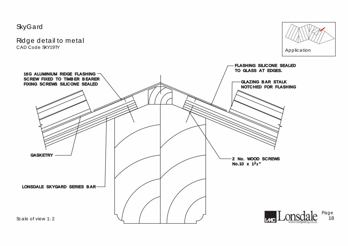
Ridge detail to metal CAD Code SKY19MY
Scale of view 1: 2
Page 17
EPDM GASKETSEPDM GASKETS
LONSDALE SKYGARD LONSDALE SKYGARD
TOP FIXING SHOE RIVETTED TO BARTOP FIXING SHOE RIVETTED TO BAR
SINGLE HOLE M8 x 25mm POSITIVESINGLE HOLE M8 x 25mm POSITIVE
BI-METALLIC CORROSION BETWEENBI-METALLIC CORROSION BETWEEN
SUITABLE ISOLATOR TO AVOIDSUITABLE ISOLATOR TO AVOID
DIS-SIMILAR METALSDIS-SIMILAR METALS
SERIES BARSERIES BAR
GLAZING BAR STALK GLAZING BAR STALK
NOTCHED FOR FLASHINGNOTCHED FOR FLASHING
FIXING SCREWS SILICONE SEALEDFIXING SCREWS SILICONE SEALED
16G ALUMINIUM RIDGE FLASHING16G ALUMINIUM RIDGE FLASHING
SCREW FIXED TO TIMBER BEARER SCREW FIXED TO TIMBER BEARER
SHAPED TIMBER BEARER SECURED TO SHAPED TIMBER BEARER SECURED TO
RIDGE STRUCTURERIDGE STRUCTURE
TO GLASS AT EDGES.TO GLASS AT EDGES.
FLASHING SILICONE SEALEDFLASHING SILICONE SEALED
Application
SkyGard
Ridge detail to metal CAD Code SKY19TY
Scale of view 1: 2
Page 18
2 No. WOOD SCREWS2 No. WOOD SCREWS
No.10 x 1 "No.10 x 1 "
GASKETRYGASKETRY
LONSDALE SKYGARD SERIES BARLONSDALE SKYGARD SERIES BAR
11//22
GLAZING BAR STALK GLAZING BAR STALK
NOTCHED FOR FLASHINGNOTCHED FOR FLASHING
SCREW FIXED TO TIMBER BEARER SCREW FIXED TO TIMBER BEARER
16G ALUMINIUM RIDGE FLASHING16G ALUMINIUM RIDGE FLASHING
FIXING SCREWS SILICONE SEALEDFIXING SCREWS SILICONE SEALED
TO GLASS AT EDGES.TO GLASS AT EDGES.
FLASHING SILICONE SEALEDFLASHING SILICONE SEALED
Application

SkyGard Intermediate roof detail to timber/steel CAD Code SKY21Y
Tiered roof detail to metal CAD Code SKY23MY
Scale of views 1-2
Page 19
GLAZING BAR RETAINED TOGLAZING BAR RETAINED TO
PURLIN WITH SLIDING PURLIN WITH SLIDING LONSDALE GLAZING BARLONSDALE GLAZING BAR
GASKETGASKET
FIXING SHOEFIXING SHOE
PURLINPURLIN
LINE OF INTERMEDIATELINE OF INTERMEDIATE
LONSDALE SKYGARD SERIESLONSDALE SKYGARD SERIES
GLAZING BAR GLAZING BAR
LONSDALE GLAZING BARS NOTCHEDLONSDALE GLAZING BARS NOTCHED
TO FACILITATE LEAD FLASHING TO FACILITATE LEAD FLASHING
END STOPEND STOPSLIDING M8 SINGLE HOLE FIXINGSLIDING M8 SINGLE HOLE FIXING
SHOE WITH ISOLATOR TO AVOIDSHOE WITH ISOLATOR TO AVOID
BI-METALLIC CORROSION BETWEENBI-METALLIC CORROSION BETWEEN
DIS-SIMILAR METALSDIS-SIMILAR METALS
MIN. 125mm
MIN. 125mm
SINGLE HOLE M8 x 25mm POSITIVESINGLE HOLE M8 x 25mm POSITIVE
TOP FIXING SHOE RIVETTED TO BARTOP FIXING SHOE RIVETTED TO BAR
EXCLUDEREXCLUDER
BLACK PVC-U DRAUGHT BLACK PVC-U DRAUGHT
Application
Application

SkyGard
Tiered roof detail to timber CAD Code SKY23TY
Scale of view 1: 2
Page 20
LEAD FLASHINGLEAD FLASHINGLONSDALE SKYGARD SERIESLONSDALE SKYGARD SERIES
GLAZING BAR GLAZING BAR
LONSDALE GLAZING BAR FIXEDLONSDALE GLAZING BAR FIXED
DIRECTLY TO PURLIN WITH 2 No.DIRECTLY TO PURLIN WITH 2 No.
No.10 x 1 " WOOD SCREWSNo.10 x 1 " WOOD SCREWS
LONSDALE GLAZING BARS NOTCHEDLONSDALE GLAZING BARS NOTCHED
OUT FOR LEAD FLASHING OUT FOR LEAD FLASHING
/1 2
MIN. 125mm
MIN. 125mm
SLIDING BOTTOMSLIDING BOTTOM
FIXING SHOEFIXING SHOE
EXCLUDEREXCLUDER
BLACK PVC-U DRAUGHT BLACK PVC-U DRAUGHT
Application

SkyGard Vertical head fixing to steel CAD Code SKY24MY
Vertical head fixing to timber CAD Code SKY24TY
Scale of views 1-2
Page 21
PRESSED ALUMINIUMPRESSED ALUMINIUM
HEAD FLASHINGHEAD FLASHING
LONSDALE SKYGARD SERIES LONSDALE SKYGARD SERIES
GLAZING BARGLAZING BAR
SUITABLE ISOLATOR TO AVOIDSUITABLE ISOLATOR TO AVOID
BI-METALLIC CORROSIONBI-METALLIC CORROSION
BETWEEN DIS-SIMILAR METALSBETWEEN DIS-SIMILAR METALS
SINGLE HOLE M8 x 25mm POSITIVESINGLE HOLE M8 x 25mm POSITIVE
TOP FIXING SHOE RIVETTED TO BARTOP FIXING SHOE RIVETTED TO BAR
EXCLUDEREXCLUDER
BLACK PVC-U DRAUGHT BLACK PVC-U DRAUGHT
16G PRESSED ALUMINIUM16G PRESSED ALUMINIUM
HEAD FLASHINGHEAD FLASHINGLONSDALE SKYGARD SERIESLONSDALE SKYGARD SERIES
GLAZING BAR FIXED DIRECTLY T0 GLAZING BAR FIXED DIRECTLY T0
TIMBER WITH 2 No. No.10 x 1 "TIMBER WITH 2 No. No.10 x 1 "
WOODSCREWSWOODSCREWS
1/2
EXCLUDEREXCLUDER
BLACK PVC-U DRAUGHT BLACK PVC-U DRAUGHT
Application
Application

SkyGard Vertical cill to metal CAD Code SKY25MY
Vertical cill to timber CAD Code SKY25TY
Scale of views 1-2
Page 22
PRESSED ALUMINIUMPRESSED ALUMINIUMCILL FLASHINGCILL FLASHING
LONSDALE SKYGARD SERIESLONSDALE SKYGARD SERIESGLAZING BARGLAZING BAR
SUITABLE ISOLATOR TOSUITABLE ISOLATOR TOAVOID BI-METALLICAVOID BI-METALLICCORROSION BETWEENCORROSION BETWEENDIS-SIMILAR METALSDIS-SIMILAR METALS
GASKETGASKET
FIXING SHOEFIXING SHOESLIDING BOTTOMSLIDING BOTTOM
FULL WIDTH FULL WIDTH GLASS SEATINGGLASS SEATING
EXCLUDEREXCLUDERBLACK PVC-U DRAUGHT BLACK PVC-U DRAUGHT
LONSDALE SKYGARD SERIESLONSDALE SKYGARD SERIES
PRESSED ALUMINIUMPRESSED ALUMINIUM
CILL FLASHINGCILL FLASHING
GLAZING BAR.GLAZING BAR.
FULL WIDTHFULL WIDTH
GLASS SEATINGGLASS SEATING
EXCLUDEREXCLUDER
BLACK PVC-U DRAUGHT BLACK PVC-U DRAUGHT
Application
Application
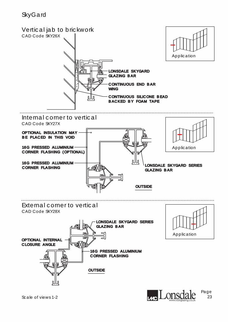
SkyGard Vertical jab to brickwork CAD Code SKY26X
Internal corner to vertical CAD Code SKY27X
External corner to vertical CAD Code SKY28X
Scale of views 1-2
Page 23
CONTINUOUS END BARCONTINUOUS END BAR
WINGWING
LONSDALE SKYGARDLONSDALE SKYGARD
GLAZING BARGLAZING BAR
CONTINUOUS SILICONE BEADCONTINUOUS SILICONE BEAD
BACKED BY FOAM TAPEBACKED BY FOAM TAPE
OPTIONAL INSULATION MAYOPTIONAL INSULATION MAY
BE PLACED IN THIS VOIDBE PLACED IN THIS VOID
16G PRESSED ALUMINIUM16G PRESSED ALUMINIUM
CORNER FLASHING (OPTIONAL)CORNER FLASHING (OPTIONAL)
CORNER FLASHINGCORNER FLASHING
16G PRESSED ALUMINIUM16G PRESSED ALUMINIUM
OUTSIDEOUTSIDE
LONSDALE SKYGARD SERIES LONSDALE SKYGARD SERIES
GLAZING BAR GLAZING BAR
LONSDALE SKYGARD SERIES LONSDALE SKYGARD SERIES
GLAZING BAR GLAZING BAR
CORNER FLASHINGCORNER FLASHING
16G PRESSED ALUMINIUM16G PRESSED ALUMINIUM
OUTSIDEOUTSIDE
OPTIONAL INTERNALOPTIONAL INTERNAL
CLOSURE ANGLECLOSURE ANGLE
Application
Application
Application

SkyGard Vertical intermediate detail CAD Code SKY29MY
Verge CAD Code SKY31X
Scale of views 1-2
Page 24
PRESSED ALUMINIUM PRESSED ALUMINIUM
LONSDALE SKYGARD SERIESLONSDALE SKYGARD SERIES
GLAZING BARGLAZING BARBOTTOM FIXING SHOE OR SECUREDBOTTOM FIXING SHOE OR SECUREDSLIDING SINGLE HOLE M8 x 25mmSLIDING SINGLE HOLE M8 x 25mm
FLASHINGFLASHINGSINGLE HOLE M8 x 25mm POSITIVESINGLE HOLE M8 x 25mm POSITIVE
TOP FIXING SHOE RIVETTED TO BARTOP FIXING SHOE RIVETTED TO BAR
WITH No.10x1WITH No.10x11122" WOODSCREWS IF" WOODSCREWS IF
FIXING TO TIMBER.FIXING TO TIMBER.
LINE OF INTERMEDIATE SUPPORT.LINE OF INTERMEDIATE SUPPORT.
FULL WIDTH GLASS SEATINGFULL WIDTH GLASS SEATING
(DELETE IF FIXING TO TIMBER)(DELETE IF FIXING TO TIMBER)
EXCLUDEREXCLUDER
BLACK PVC-U DRAUGHT BLACK PVC-U DRAUGHT
CONTINUOUS END BARCONTINUOUS END BAR
WINGWING
LONSDALE SKYGARD SERIESLONSDALE SKYGARD SERIES
GLAZING BARGLAZING BAR
SECURED WITH SELF-TAPPING SCREWSECURED WITH SELF-TAPPING SCREW
Application
Application

SkyGard
Lead flashing to steel ridge/hip CAD Code SKY32MY – see also page 21 CAD Code SKY18MY
Scale of view 1: 2
Page 25
LEAD FLASHING DRESSEDLEAD FLASHING DRESSED
SINGLE HOLE M8 x 25mmSINGLE HOLE M8 x 25mm
POSITIVE TOP FIXING SHOEPOSITIVE TOP FIXING SHOE
RIVETTED TO BARRIVETTED TO BAR
SUITABLE ISOLATOR TO AVOIDSUITABLE ISOLATOR TO AVOID
BI-METAL CORROSION BETWEENBI-METAL CORROSION BETWEEN
DIS-SIMILAR METALSDIS-SIMILAR METALS
GASKETRYGASKETRY
NOTCHED FOR FLASHINGNOTCHED FOR FLASHING
GLAZING BAR STALK GLAZING BAR STALK
OVER STEEL & ONTO GLASSOVER STEEL & ONTO GLASS
STEEL HIP/RIDGE PLATESTEEL HIP/RIDGE PLATE
Application
SkyGard
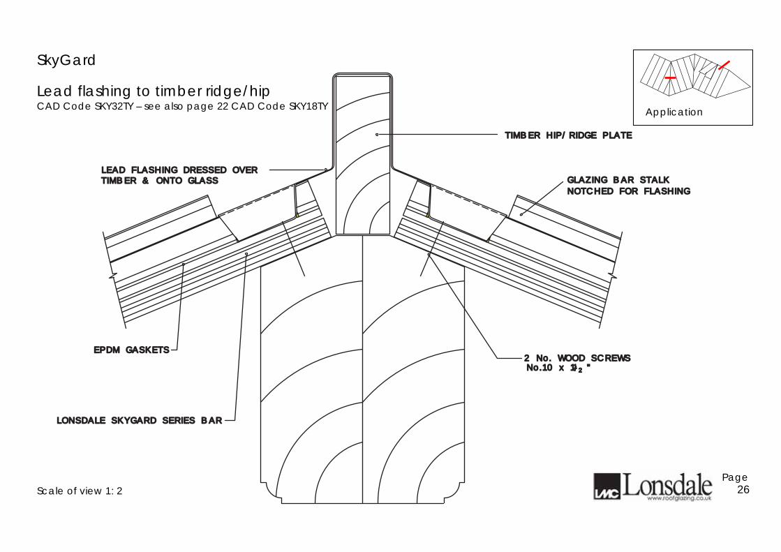
Lead flashing to timber ridge/hip CAD Code SKY32TY – see also page 22 CAD Code SKY18TY
Scale of view 1: 2
Page 26
2 No. WOOD SCREWS2 No. WOOD SCREWSNo.10 x 1 "No.10 x 1 "
EPDM GASKETSEPDM GASKETS
LONSDALE SKYGARD SERIES BARLONSDALE SKYGARD SERIES BAR
11//22
LEAD FLASHING DRESSED OVERLEAD FLASHING DRESSED OVERGLAZING BAR STALK GLAZING BAR STALK
NOTCHED FOR FLASHINGNOTCHED FOR FLASHINGTIMBER & ONTO GLASSTIMBER & ONTO GLASS
TIMBER HIP/RIDGE PLATETIMBER HIP/RIDGE PLATE
Application

Research & Development Lonsdale has made a very significant investment in research and development to bring you the products set out in this publication. Lonsdale's intention is to continue to invest to stay at the fore front of its Industry and bring its customers products with unrivalled technological advancements and standards. We reserve the right to make changes without prior notification to achieve these aims. Lonsdale will attack any Infringement of its copyright in order that both its customers and the Company may obtain the full benefits of its endeavours. Any unauthorised copying or reproduction of the plans and ideas whose copyright belongs to Lonsdale in this brochure will be met by legal action from the Company's solicitors Messrs. H. Montlake & Co. February 2009
www.roofglazing.co.uk Page 27
Related Documents


