Journal of Constructional Steel Research 64 (2008) 670–679 www.elsevier.com/locate/jcsr Longitudinal cracking of concrete slabs in composite beams with ribbed metal deck Ezzat H. Fahmy a,* , Talaat F. Abu-Amra b a Department of Construction Engineering, The American University in Cairo, Cairo, Egypt b Department of Civil and Environmental Engineering, University of Alabama at Birmingham, Birmingham, AL, USA Received 24 January 2007; accepted 8 December 2007 Abstract The results of three-dimensional finite element investigation to study the longitudinal cracking phenomena in the slab of composite steel–concrete beams with ribbed metal deck are presented. The effect of eight parameters on the development of longitudinal cracking is investigated. These parameters are: type of loading, compressive strength of the concrete slab, yield stress of the steel beam, beam span to slab width ratio, steel beam size, existence of the ribbed metal deck, height of the ribbed metal deck, and percentage of transverse reinforcement in the slab. Design curves correlating the moment at which the longitudinal cracking initiates to span to width ratio, percentage of transverse reinforcement, F y / f C , and degree of shear connection are also presented in this paper. c 2007 Elsevier Ltd. All rights reserved. Keywords: Composite beams; Longitudinal cracking; Longitudinal shear; Ultimate strength 1. Introduction Several investigators have studied the phenomenon of longitudinal cracking of the concrete slab in composite steel–concrete beams. Each of the previous investigations addressed experimentally and/or analytically the nature and origin of the longitudinal cracking in composite beams. It was concluded that longitudinal cracking could be initiated either at the bottom or at the top of the concrete slab. Davies [1] reported the results of experimental tests of composite beams with solid slab loaded with a single concentrated load at mid-span. He concluded that for this type of loading longitudinal cracking would most likely start at the bottom of the slab and then propagate to the upper surface. Azmi [2] studied experimentally the longitudinal cracking phenomenon in composite beams with ribbed concrete slab on 76 mm deep metal deck. He reported that the deck contributes with the transverse reinforcement of the slab in resisting the longitudinal cracking. El-Ghazzi et al. [3] presented a theoretical formula for determining the amount of transverse reinforcement * Corresponding author. Tel.: +20 27975813; fax: +20 2794 8861. E-mail address: [email protected] (E.H. Fahmy). required for achieving the occurrence of longitudinal cracking simultaneously with reaching the ultimate moment of the composite beam. They also reported that the compressive strength of the slab, the slab width, and the shear span were found to be important parameters when estimating the longitudinal shear capacity of the slab. The shear span in that paper was considered as the distance between the zero-moment and maximum moment sections in which the shear connecters are placed to achieve the moment capacity of the composite beam. Elkelish and Robinson [4] presented the results of an analytical investigation of the longitudinal cracking in composite beams with ribbed metal deck using the layered finite element technique. Complete interaction between the concrete slab and the steel beam was assumed in their analysis. They concluded that longitudinal cracking occurs first at the bottom of the slab when the beam was subjected to point loading applied over the steel beam while it starts at the top of the slab when the beam was subjected to a uniformly distributed load over the slab area. Study of some affecting parameters was presented in that paper. Thimmhardy et al. [5] performed experimental testing and numerical analysis on composite beams subjected to two point 0143-974X/$ - see front matter c 2007 Elsevier Ltd. All rights reserved. doi:10.1016/j.jcsr.2007.12.011

Welcome message from author
This document is posted to help you gain knowledge. Please leave a comment to let me know what you think about it! Share it to your friends and learn new things together.
Transcript
Journal of Constructional Steel Research 64 (2008) 670–679www.elsevier.com/locate/jcsr
Longitudinal cracking of concrete slabs in composite beams withribbed metal deck
Ezzat H. Fahmya,∗, Talaat F. Abu-Amrab
a Department of Construction Engineering, The American University in Cairo, Cairo, Egyptb Department of Civil and Environmental Engineering, University of Alabama at Birmingham, Birmingham, AL, USA
Received 24 January 2007; accepted 8 December 2007
Abstract
The results of three-dimensional finite element investigation to study the longitudinal cracking phenomena in the slab of compositesteel–concrete beams with ribbed metal deck are presented. The effect of eight parameters on the development of longitudinal cracking isinvestigated. These parameters are: type of loading, compressive strength of the concrete slab, yield stress of the steel beam, beam span toslab width ratio, steel beam size, existence of the ribbed metal deck, height of the ribbed metal deck, and percentage of transverse reinforcementin the slab. Design curves correlating the moment at which the longitudinal cracking initiates to span to width ratio, percentage of transversereinforcement, Fy/ f ′
C , and degree of shear connection are also presented in this paper.c© 2007 Elsevier Ltd. All rights reserved.
Keywords: Composite beams; Longitudinal cracking; Longitudinal shear; Ultimate strength
1. Introduction
Several investigators have studied the phenomenon oflongitudinal cracking of the concrete slab in compositesteel–concrete beams. Each of the previous investigationsaddressed experimentally and/or analytically the nature andorigin of the longitudinal cracking in composite beams. It wasconcluded that longitudinal cracking could be initiated either atthe bottom or at the top of the concrete slab.
Davies [1] reported the results of experimental testsof composite beams with solid slab loaded with a singleconcentrated load at mid-span. He concluded that for this typeof loading longitudinal cracking would most likely start at thebottom of the slab and then propagate to the upper surface.
Azmi [2] studied experimentally the longitudinal crackingphenomenon in composite beams with ribbed concrete slab on76 mm deep metal deck. He reported that the deck contributeswith the transverse reinforcement of the slab in resisting thelongitudinal cracking.
El-Ghazzi et al. [3] presented a theoretical formulafor determining the amount of transverse reinforcement
∗ Corresponding author. Tel.: +20 27975813; fax: +20 2794 8861.E-mail address: [email protected] (E.H. Fahmy).
0143-974X/$ - see front matter c© 2007 Elsevier Ltd. All rights reserved.doi:10.1016/j.jcsr.2007.12.011
required for achieving the occurrence of longitudinal crackingsimultaneously with reaching the ultimate moment of thecomposite beam. They also reported that the compressivestrength of the slab, the slab width, and the shear spanwere found to be important parameters when estimating thelongitudinal shear capacity of the slab. The shear span in thatpaper was considered as the distance between the zero-momentand maximum moment sections in which the shear connectersare placed to achieve the moment capacity of the compositebeam.
Elkelish and Robinson [4] presented the results ofan analytical investigation of the longitudinal cracking incomposite beams with ribbed metal deck using the layeredfinite element technique. Complete interaction between theconcrete slab and the steel beam was assumed in their analysis.They concluded that longitudinal cracking occurs first at thebottom of the slab when the beam was subjected to pointloading applied over the steel beam while it starts at the top ofthe slab when the beam was subjected to a uniformly distributedload over the slab area. Study of some affecting parameters waspresented in that paper.
Thimmhardy et al. [5] performed experimental testing andnumerical analysis on composite beams subjected to two point
E.H. Fahmy, T.F. Abu-Amra / Journal of Constructional Steel Research 64 (2008) 670–679 671
Notation
b Slab widthf ′c Compressive strength of concrete slab
Fy Yield stress of the steel beamL Span of the composite beamMy Moment at the onset of yielding of the steel
section of the composite beamMLC Moment at the onset of longitudinal cracking of
the slab of the composite beamMu Computed ultimate moment of the composite
beam from the finite element analysisM ′
u Computed ultimate moment by the stress blockmethod
loads. They concluded that longitudinal cracks start at thebottom of the slab under the load and propagate upwards.
Piotter [6] presented the results of four tests on two typesof floor systems that had two exterior girders in the form ofjoist girders or hot-rolled shapes and one interior joist girder.The three girders were joined together at the third pointsby steel joists. The systems were covered with a 125 mmconcrete slab incorporating 50 mm high ribbed metal deck. Theexperimental results showed that some degree of longitudinalsplitting occurred in the slab over all the steel members in sometests while it appeared over some of the steel members in therest of the tests, which indicates that insufficient reinforcementwas available to prevent that type of cracking. He also presenteda theoretical method to determine the required amount oftransverse reinforcement in the slab.
This paper presents the results of an analytical investigationof the longitudinal cracking phenomenon in composite beamsincorporating ribbed metal deck with incomplete interaction. Athree-dimensional finite element model using ABAQUS [7] isused in the present analysis.
Eight parameters are identified as having effects on thelongitudinal cracking of the slab, namely, type of loading (asingle point load, two point loads applied at a third point of thespan, and uniformly distributed load over the entire slab area),compressive strength of the concrete slab ( f ′
C ), yield stress ofthe steel beam (Fy), beam span to slab width ratio (L/b), sizeof the steel beam, existence of the metal deck, height of themetal deck, and percentage of transverse reinforcement in theslab.
The results presented answer the question of where thelongitudinal crack starts and how the parameters identifiedaffect the occurrence of the longitudinal cracks.
2. Summary of the analytical model
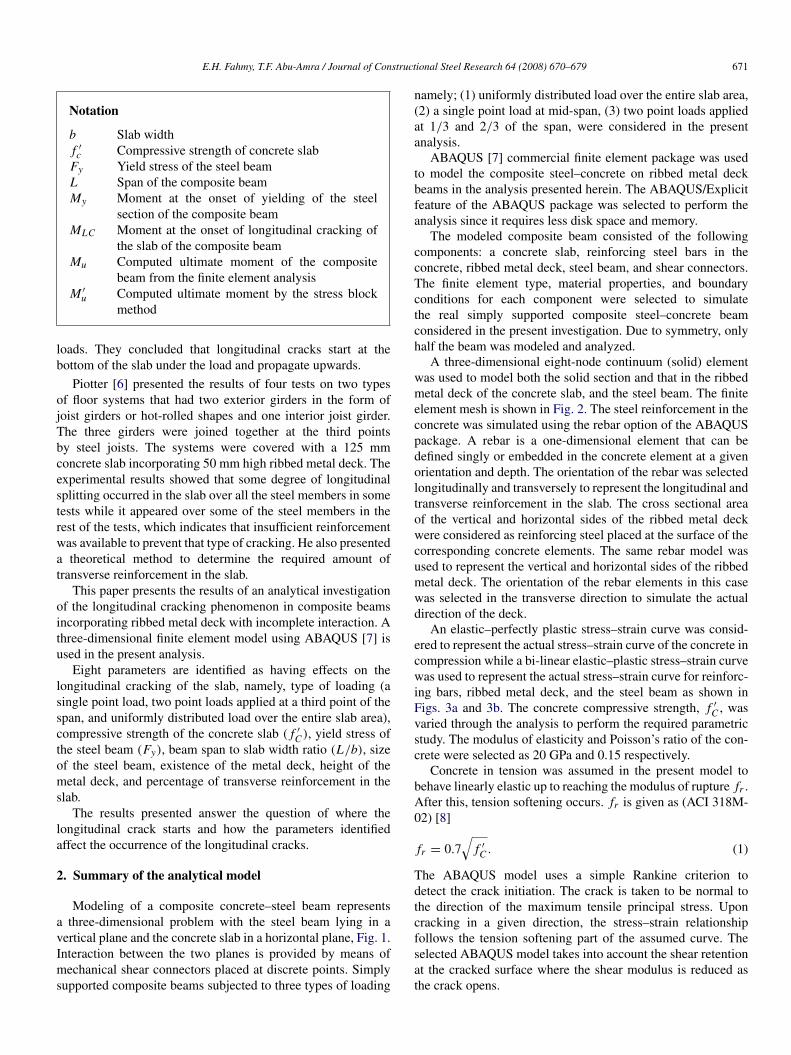
Modeling of a composite concrete–steel beam representsa three-dimensional problem with the steel beam lying in avertical plane and the concrete slab in a horizontal plane, Fig. 1.Interaction between the two planes is provided by means ofmechanical shear connectors placed at discrete points. Simplysupported composite beams subjected to three types of loading
namely; (1) uniformly distributed load over the entire slab area,(2) a single point load at mid-span, (3) two point loads appliedat 1/3 and 2/3 of the span, were considered in the presentanalysis.
ABAQUS [7] commercial finite element package was usedto model the composite steel–concrete on ribbed metal deckbeams in the analysis presented herein. The ABAQUS/Explicitfeature of the ABAQUS package was selected to perform theanalysis since it requires less disk space and memory.
The modeled composite beam consisted of the followingcomponents: a concrete slab, reinforcing steel bars in theconcrete, ribbed metal deck, steel beam, and shear connectors.The finite element type, material properties, and boundaryconditions for each component were selected to simulatethe real simply supported composite steel–concrete beamconsidered in the present investigation. Due to symmetry, onlyhalf the beam was modeled and analyzed.
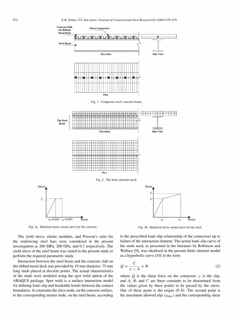
A three-dimensional eight-node continuum (solid) elementwas used to model both the solid section and that in the ribbedmetal deck of the concrete slab, and the steel beam. The finiteelement mesh is shown in Fig. 2. The steel reinforcement in theconcrete was simulated using the rebar option of the ABAQUSpackage. A rebar is a one-dimensional element that can bedefined singly or embedded in the concrete element at a givenorientation and depth. The orientation of the rebar was selectedlongitudinally and transversely to represent the longitudinal andtransverse reinforcement in the slab. The cross sectional areaof the vertical and horizontal sides of the ribbed metal deckwere considered as reinforcing steel placed at the surface of thecorresponding concrete elements. The same rebar model wasused to represent the vertical and horizontal sides of the ribbedmetal deck. The orientation of the rebar elements in this casewas selected in the transverse direction to simulate the actualdirection of the deck.
An elastic–perfectly plastic stress–strain curve was consid-ered to represent the actual stress–strain curve of the concrete incompression while a bi-linear elastic–plastic stress–strain curvewas used to represent the actual stress–strain curve for reinforc-ing bars, ribbed metal deck, and the steel beam as shown inFigs. 3a and 3b. The concrete compressive strength, f ′
C , wasvaried through the analysis to perform the required parametricstudy. The modulus of elasticity and Poisson’s ratio of the con-crete were selected as 20 GPa and 0.15 respectively.
Concrete in tension was assumed in the present model tobehave linearly elastic up to reaching the modulus of rupture fr .After this, tension softening occurs. fr is given as (ACI 318M-02) [8]
fr = 0.7√
f ′
C . (1)
The ABAQUS model uses a simple Rankine criterion todetect the crack initiation. The crack is taken to be normal tothe direction of the maximum tensile principal stress. Uponcracking in a given direction, the stress–strain relationshipfollows the tension softening part of the assumed curve. Theselected ABAQUS model takes into account the shear retentionat the cracked surface where the shear modulus is reduced asthe crack opens.
672 E.H. Fahmy, T.F. Abu-Amra / Journal of Constructional Steel Research 64 (2008) 670–679
Fig. 1. Composite steel–concrete beam.
Fig. 2. The finite element mesh.
Fig. 3a. Idealized stress–strain curve for the concrete.
The yield stress, elastic modulus, and Poisson’s ratio forthe reinforcing steel bars were considered in the presentinvestigation as 260 MPa, 200 GPa, and 0.3 respectively. Theyield stress of the steel beam was varied in the present study toperform the required parametric study.
Interaction between the steel beam and the concrete slab onthe ribbed metal deck was provided by 19 mm diameter, 75 mmlong studs placed at discrete points. The actual characteristicsof the studs were modeled using the spot weld option of theABAQUS package. Spot weld is a surface interaction modelfor defining load–slip and breakable bonds between the contactboundaries. It constrains the slave node, on the concrete surface,to the corresponding master node, on the steel beam, according
Fig. 3b. Idealized stress–strain curve for the steel.
to the prescribed load–slip relationship of the connectors up tofailure of the interaction element. The actual load–slip curve ofthe studs used, as presented in the literature by Robinson andWallace [9], was idealized in the present finite element modelas a hyperbolic curve [10] in the form
Q =C
γ − A+ B (2)
where Q is the shear force on the connector, γ is the slip,and A, B, and C are three constants to be determined fromthe values given by three points to be passed by the curve.One of these point is the origin (0, 0). The second point isthe maximum allowed slip (γmax) and the corresponding shear
E.H. Fahmy, T.F. Abu-Amra / Journal of Constructional Steel Research 64 (2008) 670–679 673
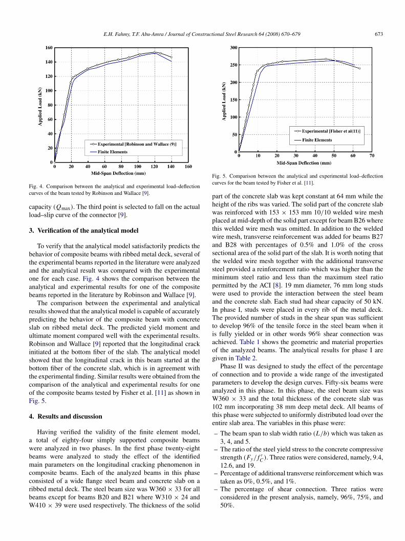
Fig. 4. Comparison between the analytical and experimental load–deflectioncurves of the beam tested by Robinson and Wallace [9].
capacity (Qmax). The third point is selected to fall on the actualload–slip curve of the connector [9].
3. Verification of the analytical model
To verify that the analytical model satisfactorily predicts thebehavior of composite beams with ribbed metal deck, several ofthe experimental beams reported in the literature were analyzedand the analytical result was compared with the experimentalone for each case. Fig. 4 shows the comparison between theanalytical and experimental results for one of the compositebeams reported in the literature by Robinson and Wallace [9].
The comparison between the experimental and analyticalresults showed that the analytical model is capable of accuratelypredicting the behavior of the composite beam with concreteslab on ribbed metal deck. The predicted yield moment andultimate moment compared well with the experimental results.Robinson and Wallace [9] reported that the longitudinal crackinitiated at the bottom fiber of the slab. The analytical modelshowed that the longitudinal crack in this beam started at thebottom fiber of the concrete slab, which is in agreement withthe experimental finding. Similar results were obtained from thecomparison of the analytical and experimental results for oneof the composite beams tested by Fisher et al. [11] as shown inFig. 5.
4. Results and discussion
Having verified the validity of the finite element model,a total of eighty-four simply supported composite beamswere analyzed in two phases. In the first phase twenty-eightbeams were analyzed to study the effect of the identifiedmain parameters on the longitudinal cracking phenomenon incomposite beams. Each of the analyzed beams in this phaseconsisted of a wide flange steel beam and concrete slab on aribbed metal deck. The steel beam size was W360 × 33 for allbeams except for beams B20 and B21 where W310 × 24 andW410 × 39 were used respectively. The thickness of the solid
Fig. 5. Comparison between the analytical and experimental load–deflectioncurves for the beam tested by Fisher et al. [11].
part of the concrete slab was kept constant at 64 mm while theheight of the ribs was varied. The solid part of the concrete slabwas reinforced with 153 × 153 mm 10/10 welded wire meshplaced at mid-depth of the solid part except for beam B26 wherethis welded wire mesh was omitted. In addition to the weldedwire mesh, transverse reinforcement was added for beams B27and B28 with percentages of 0.5% and 1.0% of the crosssectional area of the solid part of the slab. It is worth noting thatthe welded wire mesh together with the additional transversesteel provided a reinforcement ratio which was higher than theminimum steel ratio and less than the maximum steel ratiopermitted by the ACI [8]. 19 mm diameter, 76 mm long studswere used to provide the interaction between the steel beamand the concrete slab. Each stud had shear capacity of 50 kN.In phase I, studs were placed in every rib of the metal deck.The provided number of studs in the shear span was sufficientto develop 96% of the tensile force in the steel beam when itis fully yielded or in other words 96% shear connection wasachieved. Table 1 shows the geometric and material propertiesof the analyzed beams. The analytical results for phase I aregiven in Table 2.
Phase II was designed to study the effect of the percentageof connection and to provide a wide range of the investigatedparameters to develop the design curves. Fifty-six beams wereanalyzed in this phase. In this phase, the steel beam size wasW360 × 33 and the total thickness of the concrete slab was102 mm incorporating 38 mm deep metal deck. All beams ofthis phase were subjected to uniformly distributed load over theentire slab area. The variables in this phase were:
– The beam span to slab width ratio (L/b) which was taken as3, 4, and 5.
– The ratio of the steel yield stress to the concrete compressivestrength (Fy/ f ′
C ). Three ratios were considered, namely, 9.4,12.6, and 19.
– Percentage of additional transverse reinforcement which wastaken as 0%, 0.5%, and 1%.
– The percentage of shear connection. Three ratios wereconsidered in the present analysis, namely, 96%, 75%, and50%.
674 E.H. Fahmy, T.F. Abu-Amra / Journal of Constructional Steel Research 64 (2008) 670–679
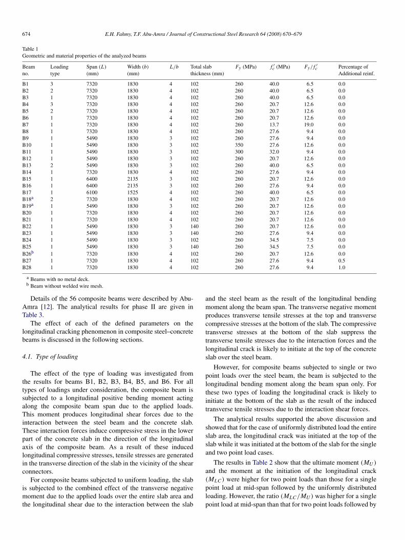
Table 1Geometric and material properties of the analyzed beams
Beamno.
Loadingtype
Span (L)
(mm)Width (b)
(mm)L/b Total slab
thickness (mm)Fy (MPa) f ′
c (MPa) Fy/ f ′c Percentage of
Additional reinf.
B1 3 7320 1830 4 102 260 40.0 6.5 0.0B2 2 7320 1830 4 102 260 40.0 6.5 0.0B3 1 7320 1830 4 102 260 40.0 6.5 0.0B4 3 7320 1830 4 102 260 20.7 12.6 0.0B5 2 7320 1830 4 102 260 20.7 12.6 0.0B6 1 7320 1830 4 102 260 20.7 12.6 0.0B7 1 7320 1830 4 102 260 13.7 19.0 0.0B8 1 7320 1830 4 102 260 27.6 9.4 0.0B9 1 5490 1830 3 102 260 27.6 9.4 0.0B10 1 5490 1830 3 102 350 27.6 12.6 0.0B11 1 5490 1830 3 102 300 32.0 9.4 0.0B12 1 5490 1830 3 102 260 20.7 12.6 0.0B13 2 5490 1830 3 102 260 40.0 6.5 0.0B14 1 7320 1830 4 102 260 27.6 9.4 0.0B15 1 6400 2135 3 102 260 20.7 12.6 0.0B16 1 6400 2135 3 102 260 27.6 9.4 0.0B17 1 6100 1525 4 102 260 40.0 6.5 0.0B18a 2 7320 1830 4 102 260 20.7 12.6 0.0B19a 1 5490 1830 3 102 260 20.7 12.6 0.0B20 1 7320 1830 4 102 260 20.7 12.6 0.0B21 1 7320 1830 4 102 260 20.7 12.6 0.0B22 1 5490 1830 3 140 260 20.7 12.6 0.0B23 1 5490 1830 3 140 260 27.6 9.4 0.0B24 1 5490 1830 3 102 260 34.5 7.5 0.0B25 1 5490 1830 3 140 260 34.5 7.5 0.0B26b 1 7320 1830 4 102 260 20.7 12.6 0.0B27 1 7320 1830 4 102 260 27.6 9.4 0.5B28 1 7320 1830 4 102 260 27.6 9.4 1.0
a Beams with no metal deck.b Beam without welded wire mesh.
Details of the 56 composite beams were described by Abu-Amra [12]. The analytical results for phase II are given inTable 3.
The effect of each of the defined parameters on thelongitudinal cracking phenomenon in composite steel–concretebeams is discussed in the following sections.
4.1. Type of loading
The effect of the type of loading was investigated fromthe results for beams B1, B2, B3, B4, B5, and B6. For alltypes of loadings under consideration, the composite beam issubjected to a longitudinal positive bending moment actingalong the composite beam span due to the applied loads.This moment produces longitudinal shear forces due to theinteraction between the steel beam and the concrete slab.These interaction forces induce compressive stress in the lowerpart of the concrete slab in the direction of the longitudinalaxis of the composite beam. As a result of these inducedlongitudinal compressive stresses, tensile stresses are generatedin the transverse direction of the slab in the vicinity of the shearconnectors.
For composite beams subjected to uniform loading, the slabis subjected to the combined effect of the transverse negativemoment due to the applied loads over the entire slab area andthe longitudinal shear due to the interaction between the slab
and the steel beam as the result of the longitudinal bendingmoment along the beam span. The transverse negative momentproduces transverse tensile stresses at the top and transversecompressive stresses at the bottom of the slab. The compressivetransverse stresses at the bottom of the slab suppress thetransverse tensile stresses due to the interaction forces and thelongitudinal crack is likely to initiate at the top of the concreteslab over the steel beam.
However, for composite beams subjected to single or twopoint loads over the steel beam, the beam is subjected to thelongitudinal bending moment along the beam span only. Forthese two types of loading the longitudinal crack is likely toinitiate at the bottom of the slab as the result of the inducedtransverse tensile stresses due to the interaction shear forces.
The analytical results supported the above discussion andshowed that for the case of uniformly distributed load the entireslab area, the longitudinal crack was initiated at the top of theslab while it was initiated at the bottom of the slab for the singleand two point load cases.
The results in Table 2 show that the ultimate moment (MU )
and the moment at the initiation of the longitudinal crack(MLC ) were higher for two point loads than those for a singlepoint load at mid-span followed by the uniformly distributedloading. However, the ratio (MLC/MU ) was higher for a singlepoint load at mid-span than that for two point loads followed by
E.H. Fahmy, T.F. Abu-Amra / Journal of Constructional Steel Research 64 (2008) 670–679 675
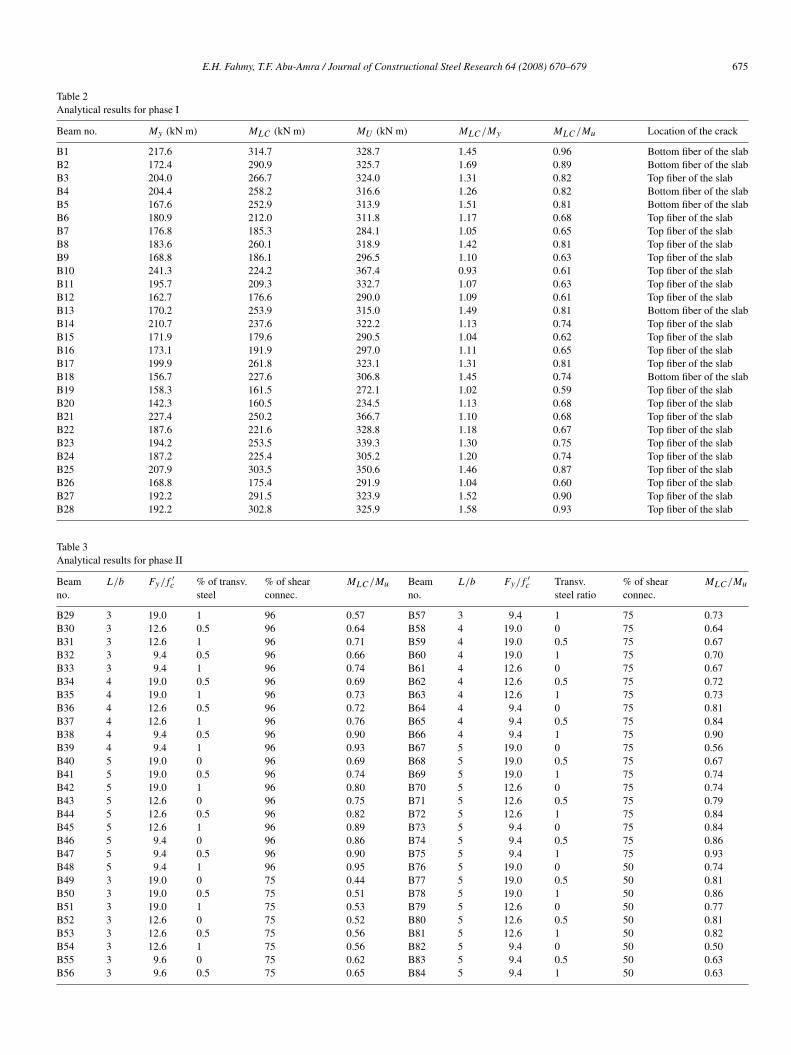
Table 2Analytical results for phase I
Beam no. My (kN m) MLC (kN m) MU (kN m) MLC /My MLC /Mu Location of the crack
B1 217.6 314.7 328.7 1.45 0.96 Bottom fiber of the slabB2 172.4 290.9 325.7 1.69 0.89 Bottom fiber of the slabB3 204.0 266.7 324.0 1.31 0.82 Top fiber of the slabB4 204.4 258.2 316.6 1.26 0.82 Bottom fiber of the slabB5 167.6 252.9 313.9 1.51 0.81 Bottom fiber of the slabB6 180.9 212.0 311.8 1.17 0.68 Top fiber of the slabB7 176.8 185.3 284.1 1.05 0.65 Top fiber of the slabB8 183.6 260.1 318.9 1.42 0.81 Top fiber of the slabB9 168.8 186.1 296.5 1.10 0.63 Top fiber of the slabB10 241.3 224.2 367.4 0.93 0.61 Top fiber of the slabB11 195.7 209.3 332.7 1.07 0.63 Top fiber of the slabB12 162.7 176.6 290.0 1.09 0.61 Top fiber of the slabB13 170.2 253.9 315.0 1.49 0.81 Bottom fiber of the slabB14 210.7 237.6 322.2 1.13 0.74 Top fiber of the slabB15 171.9 179.6 290.5 1.04 0.62 Top fiber of the slabB16 173.1 191.9 297.0 1.11 0.65 Top fiber of the slabB17 199.9 261.8 323.1 1.31 0.81 Top fiber of the slabB18 156.7 227.6 306.8 1.45 0.74 Bottom fiber of the slabB19 158.3 161.5 272.1 1.02 0.59 Top fiber of the slabB20 142.3 160.5 234.5 1.13 0.68 Top fiber of the slabB21 227.4 250.2 366.7 1.10 0.68 Top fiber of the slabB22 187.6 221.6 328.8 1.18 0.67 Top fiber of the slabB23 194.2 253.5 339.3 1.30 0.75 Top fiber of the slabB24 187.2 225.4 305.2 1.20 0.74 Top fiber of the slabB25 207.9 303.5 350.6 1.46 0.87 Top fiber of the slabB26 168.8 175.4 291.9 1.04 0.60 Top fiber of the slabB27 192.2 291.5 323.9 1.52 0.90 Top fiber of the slabB28 192.2 302.8 325.9 1.58 0.93 Top fiber of the slab
Table 3Analytical results for phase II
Beamno.
L/b Fy/ f ′c % of transv.
steel% of shearconnec.
MLC /Mu Beamno.
L/b Fy/ f ′c Transv.
steel ratio% of shearconnec.
MLC /Mu
B29 3 19.0 1 96 0.57 B57 3 9.4 1 75 0.73B30 3 12.6 0.5 96 0.64 B58 4 19.0 0 75 0.64B31 3 12.6 1 96 0.71 B59 4 19.0 0.5 75 0.67B32 3 9.4 0.5 96 0.66 B60 4 19.0 1 75 0.70B33 3 9.4 1 96 0.74 B61 4 12.6 0 75 0.67B34 4 19.0 0.5 96 0.69 B62 4 12.6 0.5 75 0.72B35 4 19.0 1 96 0.73 B63 4 12.6 1 75 0.73B36 4 12.6 0.5 96 0.72 B64 4 9.4 0 75 0.81B37 4 12.6 1 96 0.76 B65 4 9.4 0.5 75 0.84B38 4 9.4 0.5 96 0.90 B66 4 9.4 1 75 0.90B39 4 9.4 1 96 0.93 B67 5 19.0 0 75 0.56B40 5 19.0 0 96 0.69 B68 5 19.0 0.5 75 0.67B41 5 19.0 0.5 96 0.74 B69 5 19.0 1 75 0.74B42 5 19.0 1 96 0.80 B70 5 12.6 0 75 0.74B43 5 12.6 0 96 0.75 B71 5 12.6 0.5 75 0.79B44 5 12.6 0.5 96 0.82 B72 5 12.6 1 75 0.84B45 5 12.6 1 96 0.89 B73 5 9.4 0 75 0.84B46 5 9.4 0 96 0.86 B74 5 9.4 0.5 75 0.86B47 5 9.4 0.5 96 0.90 B75 5 9.4 1 75 0.93B48 5 9.4 1 96 0.95 B76 5 19.0 0 50 0.74B49 3 19.0 0 75 0.44 B77 5 19.0 0.5 50 0.81B50 3 19.0 0.5 75 0.51 B78 5 19.0 1 50 0.86B51 3 19.0 1 75 0.53 B79 5 12.6 0 50 0.77B52 3 12.6 0 75 0.52 B80 5 12.6 0.5 50 0.81B53 3 12.6 0.5 75 0.56 B81 5 12.6 1 50 0.82B54 3 12.6 1 75 0.56 B82 5 9.4 0 50 0.50B55 3 9.6 0 75 0.62 B83 5 9.4 0.5 50 0.63B56 3 9.6 0.5 75 0.65 B84 5 9.4 1 50 0.63
676 E.H. Fahmy, T.F. Abu-Amra / Journal of Constructional Steel Research 64 (2008) 670–679
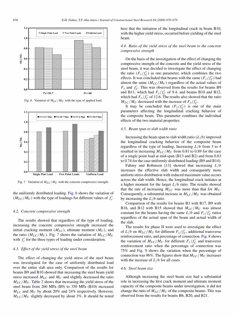
Fig. 6. Variation of MLC /MU with the type of applied load.
Fig. 7. Variation of MLC /MU with the concrete compressive strength.
the uniformly distributed loading. Fig. 6 shows the variation of(MLC/MU ) with the type of loadings for different values of f ′
c .
4.2. Concrete compressive strength
The results showed that regardless of the type of loading,increasing the concrete compressive strength increased theinitial cracking moment (MLC ), ultimate moment (MU ), andthe ratio (MLC/MU ). Fig. 7 shows the variation of MLC/MUwith f ′
c for the three types of loading under consideration.
4.3. Effect of the yield stress of the steel beam
The effect of changing the yield stress of the steel beamwas investigated for the case of uniformly distributed loadover the entire slab area only. Comparison of the results forbeams B9 and B10 showed that increasing the steel beam yieldstress increased MLC and MU and slightly decreased the ratioMLC/MU . Table 2 shows that increasing the yield stress of thesteel beam from 260 MPa (B9) to 350 MPa (B10) increasedMLC and MU by about 20% and 24% respectively. However,MLC/MU slightly decreased by about 3%. It should be noted
here that the initiation of the longitudinal crack in beam B10,with the higher yield stress, occurred before yielding of the steelbeam.
4.4. Ratio of the yield stress of the steel beam to the concretecompressive strength
On the basis of the investigation of the effect of changing thecompressive strength of the concrete and the yield stress of thesteel beam, it was decided to investigate the effect of changingthe ratio (Fy/ f ′
C ) as one parameter, which combines the twoeffects. It was concluded that beams with the same (Fy/ f ′
C ) hadalmost the same (MLC/MU ) regardless of the actual values ofFy and f ′
C . This was observed from the results for beams B9and B11, which had Fy/ f ′
C of 9.4, and beams B10 and B12,which had Fy/ f ′
C of 12.6. The results also showed that the ratioMLC/MU decreased with the increase of Fy/ f ′
C .It may be concluded that (Fy/ f ′
C ) is one of the mainparameters affecting the longitudinal cracking behavior ofthe composite beam. This parameter combines the individualeffects of the two material properties.
4.5. Beam span to slab width ratio
Increasing the beam span to slab width ratio (L/b) improvedthe longitudinal cracking behavior of the composite beamregardless of the type of loading. Increasing L/b from 3 to 4resulted in increasing MLC/MU from 0.81 to 0.89 for the caseof a single point load at mid-span (B13 and B2) and from 0.63to 0.74 for the case uniformly distributed loading (B9 and B14).
Fahmy and Robinson [13] showed that increasing L/bincreases the effective slab width and consequently moreuniform stress distribution with reduced maximum value occursacross the slab width. Hence, the longitudinal crack initiates ata higher moment for the larger L/b ratio. The results showedthat the rate of increasing MLC was more than that for MU .Consequently, a substantial increase in MLC/MU was obtainedby increasing the L/b ratio.
Comparison of the results for beams B3 with B17, B9 withB16, and B12 with B15 showed that MLC/MU was almostconstant for the beams having the same L/b and Fy/ f ′
C ratiosregardless of the actual span of the beam and actual width ofthe slab.
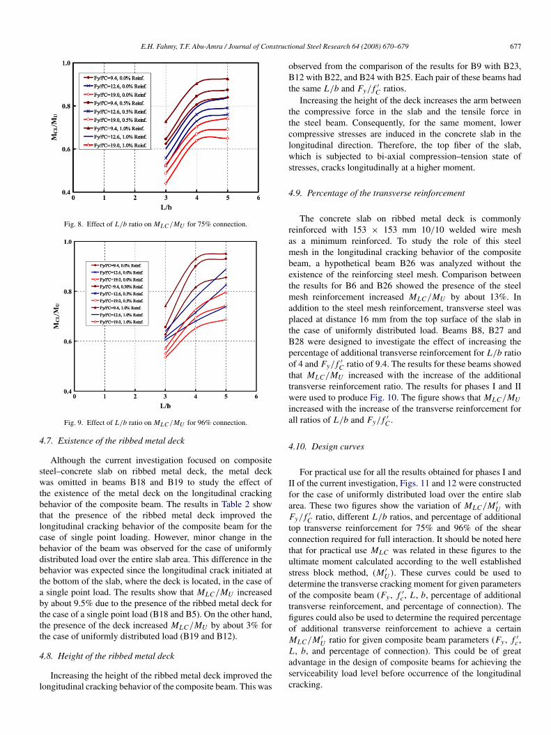
The results for phase II were used to investigate the effectof L/b on MLC/MU for different Fy/ f ′
C , additional transversereinforcement ratio, and percentage of connection. Fig. 8 showsthe variation of MLC/MU for different Fy/ f ′
C and transversereinforcement ratio when the percentage of connection was75% and Fig. 9 shows the variation when the percentage ofconnection was 96%. The figures show that MLC/MU increaseswith the increase of L/b for all cases.
4.6. Steel beam size
Although increasing the steel beam size had a substantialrole in increasing the first crack moment and ultimate momentcapacity of the composite beams under investigation, it did notchange the ratio of MLC/MU of the composite beams. This wasobserved from the results for beams B6, B20, and B21.
E.H. Fahmy, T.F. Abu-Amra / Journal of Constructional Steel Research 64 (2008) 670–679 677
Fig. 8. Effect of L/b ratio on MLC /MU for 75% connection.
Fig. 9. Effect of L/b ratio on MLC /MU for 96% connection.
4.7. Existence of the ribbed metal deck
Although the current investigation focused on compositesteel–concrete slab on ribbed metal deck, the metal deckwas omitted in beams B18 and B19 to study the effect ofthe existence of the metal deck on the longitudinal crackingbehavior of the composite beam. The results in Table 2 showthat the presence of the ribbed metal deck improved thelongitudinal cracking behavior of the composite beam for thecase of single point loading. However, minor change in thebehavior of the beam was observed for the case of uniformlydistributed load over the entire slab area. This difference in thebehavior was expected since the longitudinal crack initiated atthe bottom of the slab, where the deck is located, in the case ofa single point load. The results show that MLC/MU increasedby about 9.5% due to the presence of the ribbed metal deck forthe case of a single point load (B18 and B5). On the other hand,the presence of the deck increased MLC/MU by about 3% forthe case of uniformly distributed load (B19 and B12).
4.8. Height of the ribbed metal deck
Increasing the height of the ribbed metal deck improved thelongitudinal cracking behavior of the composite beam. This was
observed from the comparison of the results for B9 with B23,B12 with B22, and B24 with B25. Each pair of these beams hadthe same L/b and Fy/ f ′
C ratios.Increasing the height of the deck increases the arm between
the compressive force in the slab and the tensile force inthe steel beam. Consequently, for the same moment, lowercompressive stresses are induced in the concrete slab in thelongitudinal direction. Therefore, the top fiber of the slab,which is subjected to bi-axial compression–tension state ofstresses, cracks longitudinally at a higher moment.
4.9. Percentage of the transverse reinforcement
The concrete slab on ribbed metal deck is commonlyreinforced with 153 × 153 mm 10/10 welded wire meshas a minimum reinforced. To study the role of this steelmesh in the longitudinal cracking behavior of the compositebeam, a hypothetical beam B26 was analyzed without theexistence of the reinforcing steel mesh. Comparison betweenthe results for B6 and B26 showed the presence of the steelmesh reinforcement increased MLC/MU by about 13%. Inaddition to the steel mesh reinforcement, transverse steel wasplaced at distance 16 mm from the top surface of the slab inthe case of uniformly distributed load. Beams B8, B27 andB28 were designed to investigate the effect of increasing thepercentage of additional transverse reinforcement for L/b ratioof 4 and Fy/ f ′
C ratio of 9.4. The results for these beams showedthat MLC/MU increased with the increase of the additionaltransverse reinforcement ratio. The results for phases I and IIwere used to produce Fig. 10. The figure shows that MLC/MUincreased with the increase of the transverse reinforcement forall ratios of L/b and Fy/ f ′
C .
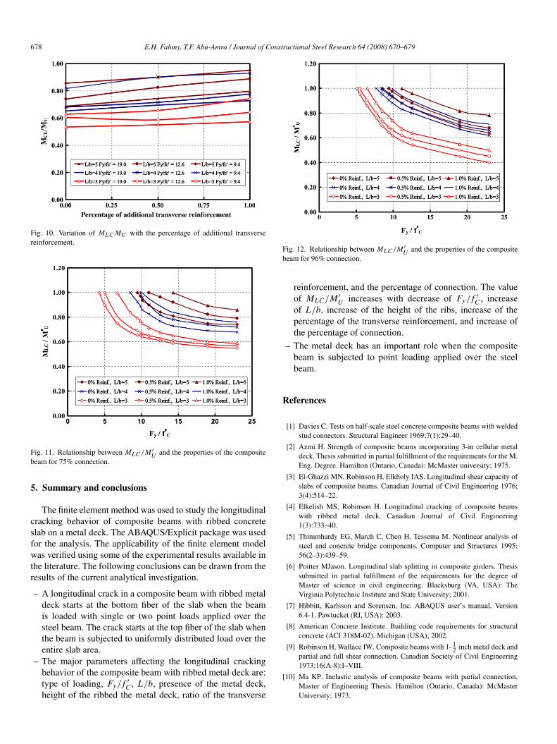
4.10. Design curves
For practical use for all the results obtained for phases I andII of the current investigation, Figs. 11 and 12 were constructedfor the case of uniformly distributed load over the entire slabarea. These two figures show the variation of MLC/M ′
U withFy/ f ′
C ratio, different L/b ratios, and percentage of additionaltop transverse reinforcement for 75% and 96% of the shearconnection required for full interaction. It should be noted herethat for practical use MLC was related in these figures to theultimate moment calculated according to the well establishedstress block method, (M ′
U ). These curves could be used todetermine the transverse cracking moment for given parametersof the composite beam (Fy , f ′
c , L , b, percentage of additionaltransverse reinforcement, and percentage of connection). Thefigures could also be used to determine the required percentageof additional transverse reinforcement to achieve a certainMLC/M ′
U ratio for given composite beam parameters (Fy , f ′c ,
L , b, and percentage of connection). This could be of greatadvantage in the design of composite beams for achieving theserviceability load level before occurrence of the longitudinalcracking.
678 E.H. Fahmy, T.F. Abu-Amra / Journal of Constructional Steel Research 64 (2008) 670–679
Fig. 10. Variation of MLC MU with the percentage of additional transversereinforcement.
Fig. 11. Relationship between MLC /M ′U and the properties of the composite
beam for 75% connection.
5. Summary and conclusions
The finite element method was used to study the longitudinalcracking behavior of composite beams with ribbed concreteslab on a metal deck. The ABAQUS/Explicit package was usedfor the analysis. The applicability of the finite element modelwas verified using some of the experimental results available inthe literature. The following conclusions can be drawn from theresults of the current analytical investigation.
– A longitudinal crack in a composite beam with ribbed metaldeck starts at the bottom fiber of the slab when the beamis loaded with single or two point loads applied over thesteel beam. The crack starts at the top fiber of the slab whenthe beam is subjected to uniformly distributed load over theentire slab area.
– The major parameters affecting the longitudinal crackingbehavior of the composite beam with ribbed metal deck are:type of loading, Fy/ f ′
C , L/b, presence of the metal deck,height of the ribbed the metal deck, ratio of the transverse
Fig. 12. Relationship between MLC /M ′U and the properties of the composite
beam for 96% connection.
reinforcement, and the percentage of connection. The valueof MLC/M ′
U increases with decrease of Fy/ f ′
C , increaseof L/b, increase of the height of the ribs, increase of thepercentage of the transverse reinforcement, and increase ofthe percentage of connection.
– The metal deck has an important role when the compositebeam is subjected to point loading applied over the steelbeam.
References
[1] Davies C. Tests on half-scale steel concrete composite beams with weldedstud connectors. Structural Engineer 1969;7(1):29–40.
[2] Azmi H. Strength of composite beams incorporating 3-in cellular metaldeck. Thesis submitted in partial fulfillment of the requirements for the M.Eng. Degree. Hamilton (Ontario, Canada): McMaster university; 1975.
[3] El-Ghazzi MN, Robinson H, Elkholy IAS. Longitudinal shear capacity ofslabs of composite beams. Canadian Journal of Civil Engineering 1976;3(4):514–22.
[4] Elkelish MS, Robinson H. Longitudinal cracking of composite beamswith ribbed metal deck. Canadian Journal of Civil Engineering1(3):733–40.
[5] Thimmhardy EG, March C, Chen H, Tessema M. Nonlinear analysis ofsteel and concrete bridge components. Computer and Structures 1995;56(2–3):439–59.
[6] Poitter MJason. Longitudinal slab splitting in composite girders. Thesissubmitted in partial fulfillment of the requirements for the degree ofMaster of science in civil engineering. Blacksburg (VA, USA): TheVirginia Polytechnic Institute and State University; 2001.
[7] Hibbitt, Karlsson and Sorensen, Inc. ABAQUS user’s manual, Version6.4-1. Pawtucket (RI, USA): 2003.
[8] American Concrete Institute. Building code requirements for structuralconcrete (ACI 318M-02). Michigan (USA); 2002.
[9] Robinson H, Wallace IW. Composite beams with 1- 12 inch metal deck and
partial and full shear connection. Canadian Society of Civil Engineering1973;16(A-8):I–VIII.
[10] Ma KP. Inelastic analysis of composite beams with partial connection,Master of Engineering Thesis. Hamilton (Ontario, Canada): McMasterUniversity; 1973.

E.H. Fahmy, T.F. Abu-Amra / Journal of Constructional Steel Research 64 (2008) 670–679 679
[11] Fisher JW, Kim SW, Slutter RG. Tests of lightweight concrete compositebridges at ultimate load. Civil engineering report no 54. USA: Universityof Maryland; 1974.
[12] Abu-Amra TalaatFawzi. Longitudinal cracking of concrete slab incomposite beams. Thesis submitted in partial fulfillment of the
requirements for the degree of Master of Science in Engineering. Cairo(Egypt): The American University in Cairo; 2000.
[13] Fahmy EH, Robinson H. Analysis and tests to determine the effectivewidths of composite beams in unbraced multi-story frames. CanadianJournal of Civil Engineering 1986;13(1):66–75.
Related Documents