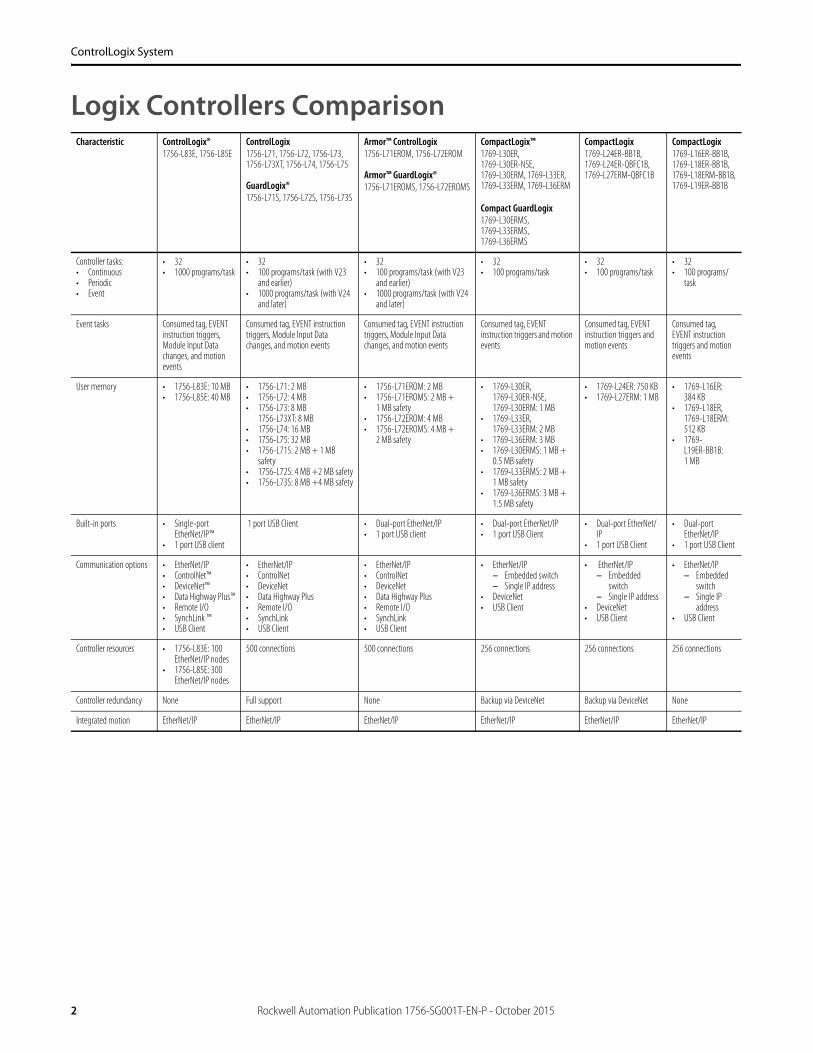
2 Rockwell Automation Publication 1756-SG001T-EN-P - October 2015 ControlLogix System Logix Controllers Comparison Characteristic ControlLogix® 1756-L83E, 1756-L85E ControlLogix 1756-L71, 1756-L72, 1756-L73, 1756-L73XT, 1756-L74, 1756-L75 GuardLogix® 1756-L71S, 1756-L72S, 1756-L73S Armor™ ControlLogix 1756-L71EROM, 1756-L72EROM Armor™ GuardLogix® 1756-L71EROMS, 1756-L72EROMS CompactLogix™ 1769-L30ER, 1769-L30ER-NSE, 1769-L30ERM, 1769-L33ER, 1769-L33ERM, 1769-L36ERM Compact GuardLogix 1769-L30ERMS, 1769-L33ERMS, 1769-L36ERMS CompactLogix 1769-L24ER-BB1B, 1769-L24ER-QBFC1B, 1769-L27ERM-QBFC1B CompactLogix 1769-L16ER-BB1B, 1769-L18ER-BB1B, 1769-L18ERM-BB1B, 1769-L19ER-BB1B Controller tasks: • Continuous • Periodic • Event • 32 • 1000 programs/task • 32 • 100 programs/task (with V23 and earlier) • 1000 programs/task (with V24 and later) • 32 • 100 programs/task (with V23 and earlier) • 1000 programs/task (with V24 and later) • 32 • 100 programs/task • 32 • 100 programs/task • 32 • 100 programs/ task Event tasks Consumed tag, EVENT instruction triggers, Module Input Data changes, and motion events Consumed tag, EVENT instruction triggers, Module Input Data changes, and motion events Consumed tag, EVENT instruction triggers, Module Input Data changes, and motion events Consumed tag, EVENT instruction triggers and motion events Consumed tag, EVENT instruction triggers and motion events Consumed tag, EVENT instruction triggers and motion events User memory • 1756-L83E: 10 MB • 1756-L85E: 40 MB • 1756-L71: 2 MB • 1756-L72: 4 MB • 1756-L73: 8 MB 1756-L73XT: 8 MB • 1756-L74: 16 MB • 1756-L75: 32 MB • 1756-L71S: 2 MB + 1 MB safety • 1756-L72S: 4 MB +2 MB safety • 1756-L73S: 8 MB +4 MB safety • 1756-L71EROM: 2 MB • 1756-L71EROMS: 2 MB + 1 MB safety • 1756-L72EROM: 4 MB • 1756-L72EROMS: 4 MB + 2 MB safety • 1769-L30ER, 1769-L30ER-NSE, 1769-L30ERM: 1 MB • 1769-L33ER, 1769-L33ERM: 2 MB • 1769-L36ERM: 3 MB • 1769-L30ERMS: 1 MB + 0.5 MB safety • 1769-L33ERMS: 2 MB + 1 MB safety • 1769-L36ERMS: 3 MB + 1.5 MB safety • 1769-L24ER: 750 KB • 1769-L27ERM: 1 MB • 1769-L16ER: 384 KB • 1769-L18ER, 1769-L18ERM: 512 KB • 1769- L19ER-BB1B: 1 MB Built-in ports • Single-port EtherNet/IP™ • 1 port USB client 1 port USB Client • Dual-port EtherNet/IP • 1 port USB client • Dual-port EtherNet/IP • 1 port USB Client • Dual-port EtherNet/ IP • 1 port USB Client • Dual-port EtherNet/IP • 1 port USB Client Communication options • EtherNet/IP • ControlNet™ • DeviceNet™ • Data Highway Plus™ • Remote I/O • SynchLink ™ • USB Client • EtherNet/IP • ControlNet • DeviceNet • Data Highway Plus • Remote I/O • SynchLink • USB Client • EtherNet/IP • ControlNet • DeviceNet • Data Highway Plus • Remote I/O • SynchLink • USB Client • EtherNet/IP – Embedded switch – Single IP address • DeviceNet • USB Client • EtherNet/IP – Embedded switch – Single IP address • DeviceNet • USB Client • EtherNet/IP – Embedded switch – Single IP address • USB Client Controller resources • 1756-L83E: 100 EtherNet/IP nodes • 1756-L85E: 300 EtherNet/IP nodes 500 connections 500 connections 256 connections 256 connections 256 connections Controller redundancy None Full support None Backup via DeviceNet Backup via DeviceNet None Integrated motion EtherNet/IP EtherNet/IP EtherNet/IP EtherNet/IP EtherNet/IP EtherNet/IP

Welcome message from author
This document is posted to help you gain knowledge. Please leave a comment to let me know what you think about it! Share it to your friends and learn new things together.
Transcript
2 Rockwell Automation Publication 1756-SG001T-EN-P - October 2015
ControlLogix System
Logix Controllers ComparisonCharacteristic ControlLogix®
1756-L83E, 1756-L85EControlLogix1756-L71, 1756-L72, 1756-L73, 1756-L73XT, 1756-L74, 1756-L75
GuardLogix®1756-L71S, 1756-L72S, 1756-L73S
Armor™ ControlLogix1756-L71EROM, 1756-L72EROM
Armor™ GuardLogix®1756-L71EROMS, 1756-L72EROMS
CompactLogix™1769-L30ER, 1769-L30ER-NSE, 1769-L30ERM, 1769-L33ER, 1769-L33ERM, 1769-L36ERM
Compact GuardLogix1769-L30ERMS, 1769-L33ERMS, 1769-L36ERMS
CompactLogix1769-L24ER-BB1B, 1769-L24ER-QBFC1B, 1769-L27ERM-QBFC1B
CompactLogix1769-L16ER-BB1B, 1769-L18ER-BB1B, 1769-L18ERM-BB1B, 1769-L19ER-BB1B
Controller tasks:• Continuous• Periodic• Event
• 32• 1000 programs/task
• 32• 100 programs/task (with V23
and earlier)• 1000 programs/task (with V24
and later)
• 32• 100 programs/task (with V23
and earlier)• 1000 programs/task (with V24
and later)
• 32• 100 programs/task
• 32• 100 programs/task
• 32• 100 programs/
task
Event tasks Consumed tag, EVENT instruction triggers, Module Input Data changes, and motion events
Consumed tag, EVENT instruction triggers, Module Input Data changes, and motion events
Consumed tag, EVENT instruction triggers, Module Input Data changes, and motion events
Consumed tag, EVENT instruction triggers and motion events
Consumed tag, EVENT instruction triggers and motion events
Consumed tag, EVENT instruction triggers and motion events
User memory • 1756-L83E: 10 MB• 1756-L85E: 40 MB
• 1756-L71: 2 MB • 1756-L72: 4 MB• 1756-L73: 8 MB
1756-L73XT: 8 MB• 1756-L74: 16 MB• 1756-L75: 32 MB• 1756-L71S: 2 MB + 1 MB
safety• 1756-L72S: 4 MB +2 MB safety• 1756-L73S: 8 MB +4 MB safety
• 1756-L71EROM: 2 MB• 1756-L71EROMS: 2 MB +
1 MB safety• 1756-L72EROM: 4 MB• 1756-L72EROMS: 4 MB +
2 MB safety
• 1769-L30ER, 1769-L30ER-NSE, 1769-L30ERM: 1 MB
• 1769-L33ER, 1769-L33ERM: 2 MB
• 1769-L36ERM: 3 MB• 1769-L30ERMS: 1 MB +
0.5 MB safety• 1769-L33ERMS: 2 MB +
1 MB safety• 1769-L36ERMS: 3 MB +
1.5 MB safety
• 1769-L24ER: 750 KB• 1769-L27ERM: 1 MB
• 1769-L16ER: 384 KB
• 1769-L18ER, 1769-L18ERM: 512 KB
• 1769-L19ER-BB1B: 1 MB
Built-in ports • Single-port EtherNet/IP™
• 1 port USB client
1 port USB Client • Dual-port EtherNet/IP• 1 port USB client
• Dual-port EtherNet/IP• 1 port USB Client
• Dual-port EtherNet/IP
• 1 port USB Client
• Dual-port EtherNet/IP
• 1 port USB Client
Communication options • EtherNet/IP• ControlNet™• DeviceNet™• Data Highway Plus™• Remote I/O• SynchLink ™• USB Client
• EtherNet/IP• ControlNet• DeviceNet• Data Highway Plus• Remote I/O• SynchLink• USB Client
• EtherNet/IP• ControlNet• DeviceNet• Data Highway Plus• Remote I/O• SynchLink• USB Client
• EtherNet/IP– Embedded switch– Single IP address
• DeviceNet• USB Client
• EtherNet/IP– Embedded
switch– Single IP address
• DeviceNet• USB Client
• EtherNet/IP– Embedded
switch– Single IP
address• USB Client
Controller resources • 1756-L83E: 100 EtherNet/IP nodes
• 1756-L85E: 300 EtherNet/IP nodes
500 connections 500 connections 256 connections 256 connections 256 connections
Controller redundancy None Full support None Backup via DeviceNet Backup via DeviceNet None
Integrated motion EtherNet/IP EtherNet/IP EtherNet/IP EtherNet/IP EtherNet/IP EtherNet/IP
Rockwell Automation Publication 1756-SG001T-EN-P - October 2015 3
Select a ControlLogix System
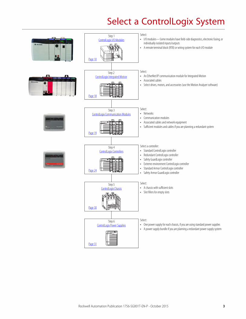
Step 1ControlLogix I/O Modules
Step 2ControlLogix Integrated Motion
Step 3ControlLogix Communication Modules
Step 4ControlLogix Controllers
Step 5ControlLogix Chassis
Step 6ControlLogix Power Supplies
Select:• I/O modules—Some modules have field-side diagnostics, electronic fusing, or
individually isolated inputs/outputs• A remote terminal block (RTB) or wiring system for each I/O module
Select:• An EtherNet/IP communication module for Integrated Motion• Associated cables• Select drives, motors, and accessories (use the Motion Analyzer software)
Select:• Networks• Communication modules• Associated cables and network equipment• Sufficient modules and cables if you are planning a redundant system
Select a controller:• Standard ControlLogix controller• Redundant ControlLogix controller• Safety GuardLogix controller• Extreme environment ControlLogix controller• Standard Armor ControlLogix controller• Safety Armor GuardLogix controller
Select:• A chassis with sufficient slots• Slot fillers for empty slots
Select:• One power supply for each chassis, if you are using standard power supplies• A power supply bundle if you are planning a redundant power supply system
Page 10
Page 18
Page 19
Page 24
Page 30
Page 31

4 Rockwell Automation Publication 1756-SG001T-EN-P - October 2015
Select a ControlLogix System
ControlLogix System OverviewThe ControlLogix system provides discrete, drives, motion, process, and safety control together with communication and state-of-the-art I/O in a small, cost-competitive package. The system is modular, so you can design, build, and modify it efficiently with significant savings in training and engineering.
Example Configuration—ControlLogix System
A simple ControlLogix system consists of a standalone controller and I/O modules in one chassis. For a more comprehensive system, use the following:
• Multiple controllers in one chassis• Multiple controllers joined across networks• I/O in multiple platforms that are distributed in many locations and connected over multiple I/O links
PowerMonitor™ 5000 Stratix 5700™PanelView™ Plus 7
PowerFlex® 755
1794 FLEX™ I/O
ControlLogix
Stratix 5700
ControlLogix
Dynamix™ 1444
1715 I/O
Rockwell Automation Publication 1756-SG001T-EN-P - October 2015 5
Select a ControlLogix System
Conformal Coating
A conformal coating solution is offered on select ControlLogix products. Conformal coating helps protect the assembly by providing a layer of protection against contaminants and humidity to extend product life in harsh, corrosive environments. Conformally coated products have a ‘K’ suffix at the end of the catalog number, such as 1756-A4K. Conformally coated, Allen-Bradley® products meet or exceed these requirements:
• ANSI/ISA 71.04.2013 G3 Environment (10-year exposure)• IEC 61086-3-1 Class 2• IPC-CC-830• MIL-I-46058C• EN600068-2-52 salt mist test, severity level 3
The most current list of conformally coated products can be found by contacting your local Rockwell Automation distributor, sales office, or at the following location:
http://www.ab.com/en/epub/catalogs/12762/2181376/2416247/360807/ControlLogix-System.html
ControlLogix-XT System
ControlLogix-XT™ (Extended Temperature) controllers function the same way as traditional ControlLogix controllers with an extended temperature range. The ControlLogix-XT products include control and communication system components that are conformally coated to extend product life in harsh, corrosive environments:
• The standard ControlLogix system can withstand temperature ranges from 0…60 °C (33…140 °F).
• When used independently, the ControlLogix-XT system can withstand temperature ranges from -25…70 C (-13…158 F).
8 Rockwell Automation Publication 1756-SG001T-EN-P - October 2015
Select a ControlLogix System
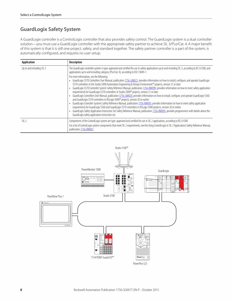
GuardLogix Safety System
A GuardLogix controller is a ControlLogix controller that also provides safety control. The GuardLogix system is a dual controller solution—you must use a GuardLogix controller with the appropriate safety partner to achieve SIL 3/PLe/Cat. 4. A major benefit of this system is that it is still one project, safety, and standard together. The safety partner controller is a part of the system, is automatically configured, and requires no user setup.
Application Description
Up to and including SIL 3 The GuardLogix controller system is type-approved and certified for use in safety applications up to and including SIL 3, according to IEC 61508, and applications up to and including category (PLe/Cat. 4), according to ISO 13849-1. For more information, see the following:• GuardLogix 5570 Controllers User Manual, publication 1756-UM022, provides information on how to install, configure, and operate GuardLogix
5570 controllers in the Studio 5000 Automation Engineering & Design Environment™ projects, version 21 or later.• GuardLogix 5570 Controller System Safety Reference Manual, publication 1756-RM099, provides information on how to meet safety application
requirements for GuardLogix 5570 controllers in Studio 5000® projects, version 21 or later.• GuardLogix Controllers User Manual, publication 1756-UM020, provides information on how to install, configure, and operate GuardLogix 5560
and GuardLogix 5570 controllers in RSLogix 5000® projects, version 20 or earlier.• GuardLogix Controller Systems Safety Reference Manual, publication 1756-RM093, provides information on how to meet safety application
requirements for GuardLogix 5560 and GuardLogix 5570 controllers in RSLogix 5000 projects, version 20 or earlier.• GuardLogix Safety Application Instruction Set Safety Reference Manual, publication 1756-RM095, provides programmers with details about the
GuardLogix safety application instruction set.
SIL 2 Components of the ControlLogix system are type-approved and certified for use in SIL 2 applications, according to IEC 61508. For a list of ControlLogix system components that meet SIL 2 requirements, see the Using ControlLogix in SIL 2 Applications Safety Reference Manual, publication 1756-RM001.
RS-485 STATUSRS-485
RX
SHLDLNK ACT
TX Mod Net
+ -
Powermonitor 1000conformance testedTM
PanelView Plus 7
PowerMonitor 1000
Stratix 5700
PowerFlex 525
1734 POINT Guard I/O™
Stratix 5100™
GuardLogix

24 Rockwell Automation Publication 1756-SG001T-EN-P - October 2015
Select a ControlLogix System
ControlLogix ControllersThe ControlLogix controller provides a scalable controller solution capable of addressing many I/O points.
The controller can be placed into any slot of a ControlLogix chassis and multiple controllers can be installed in the same chassis. Multiple controllers in the same chassis communicate with each other over the backplane (just as controllers can communicate over networks) but operate independently.
ControlLogix controllers can monitor and control I/O across the ControlLogix backplane, and over I/O links. ControlLogix controllers can communicate over EtherNet/IP, ControlNet, DeviceNet, DH+, Remote I/O, and RS-232-C (DF1/DH-485 protocol) networks and many third-party process and device networks. To provide communication for a ControlLogix controller, install the appropriate communication interface module into the chassis.
For detailed specifications, see the 1756 ControlLogix Controllers Technical Data, publication 1756-TD001.
Cat. No. Description User Memory
1756-L83E ControlLogix controller, 1 built-in USB port(1), single port EtherNet/IP 10 MB
1756-L85E 40 MB
1756-L71 ControlLogix controller, 1 built-in USB port(1)
(1) The USB port is intended only for temporary local programming purposes and not intended for permanent connection. Do not use the USB port in hazardous locations.
2 MB
1756-L72 4 MB
1756-L73 8 MB
1756-L74 16 MB
1756-L75 32 MB
1756-L73XT ControlLogix-XT controller, extreme environment 8 MB
1756-L71S GuardLogix safety controllers 2 MB standard1 MB safety
1756-L72S 4 MB standard2 MB safety
1756-L73S 8 MB standard4 MB safety
1756-L7SP GuardLogix safety partner (one is required for each GuardLogix L7 controller) —
1756-L71EROM Armor ControlLogix controllers, EtherNet/IP dual port 2 MB
1756-L72EROM 4 MB
1756-L71EROMS Armor GuardLogix controllers, EtherNet/IP dual port 2 MB standard1 MB safety
1756-L72ERMOS 4 MB standard2 MB safety
Rockwell Automation Publication 1756-SG001T-EN-P - October 2015 27
Select a ControlLogix System
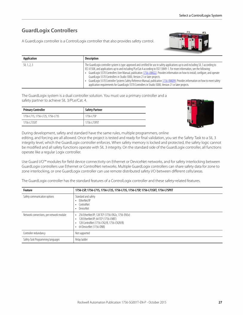
GuardLogix Controllers
A GuardLogix controller is a ControlLogix controller that also provides safety control.
The GuardLogix system is a dual controller solution. You must use a primary controller and a safety partner to achieve SIL 3/PLe/Cat. 4.
During development, safety and standard have the same rules, multiple programmers, online editing, and forcing are all allowed. Once the project is tested and ready for final validation, you set the Safety Task to a SIL 3 integrity level, which the GuardLogix controller enforces. When safety memory is locked and protected, the safety logic cannot be modified and all safety functions operate with SIL 3 integrity. On the standard side of the GuardLogix controller, all functions operate like a regular Logix controller.
Use Guard I/O™ modules for field device connectivity on Ethernet or DeviceNet networks, and for safety interlocking between GuardLogix controllers use Ethernet or ControlNet networks. Multiple GuardLogix controllers can share safety data for zone to zone interlocking, or one GuardLogix controller can use remote distributed safety I/O between different cells/areas.
The GuardLogix controller has the standard features of a ControlLogix controller and these safety-related features.
Application Description
SIL 1, 2, 3 The GuardLogix controller system is type-approved and certified for use in safety applications up to and including SIL 3 according to IEC 61508, and applications up to and including PLe/Cat.4 according to ISO 13849-1. For more information, see the following:• GuardLogix 5570 Controllers User Manual, publication 1756-UM022. Provides information on how to install, configure, and operate
GuardLogix 5570 Controllers in Studio 5000, Version 21 or later projects.• GuardLogix 5570 Controller Systems Safety Reference Manual, publication 1756-RM099. Provides information on how to meet safety
application requirements for GuardLogix 5570 Controllers in Studio 5000, Version 21 or later projects.
Primary Controller Safety Partner
1756-L71S, 1756-L72S, 1756-L73S 1756-L7SP
1756-L73SXT 1756-L7SPXT
Feature 1756-LSP, 1756-L71S, 1756-L72S, 1756-L73S, 1756-L7SP, 1756-L73SXT, 1756-L7SPXT
Safety communication options Standard and safety• EtherNet/IP• ControlNet• DeviceNet
Network connections, per network module • 256 EtherNet/IP; 128 TCP (1756-EN2x, 1756-EN3x)• 128 EtherNet/IP; 64 TCP (1756-ENBT)• 128 ControlNet (1756-CN2/B, 1756-CN2R/B)• 64 DeviceNet (1756-DNB)
Controller redundancy Not supported
Safety Task Programming languages Relay ladder
Related Documents