GE Healthcare LOGIQ e/LOGIQ e Vet/LOGIQ i/ Vivid e Basic Service Manual Part Number: 5370626-100 Revision: 7

Welcome message from author
This document is posted to help you gain knowledge. Please leave a comment to let me know what you think about it! Share it to your friends and learn new things together.
Transcript
GE Healthcare
LOGIQ e/LOGIQ e Vet/LOGIQ i/Vivid e
Basic Service Manual
Part Number: 5370626-100Revision: 7

GE HEALTHCAREDIRECTION 5370626-100, REVISION 7 LOGIQ E/LOGIQ E VET/LOGIQ I/VIVID E BASIC SERVICE MANUAL
- i
Important Precautions
THIS SERVICE MANUAL IS AVAILABLE IN ENGLISH ONLY.• IF A CUSTOMER’S SERVICE PROVIDER REQUIRES A LANGUAGE OTHER
THAN ENGLISH, IT IS THE CUSTOMER’S RESPONSIBILITY TO PROVIDE TRANSLATION SERVICES.
• DO NOT ATTEMPT TO SERVICE THE EQUIPMENT UNLESS THIS SERVICE MANUAL HAS BEEN CONSULTED AND IS UNDERSTOOD.
• FAILURE TO HEED THIS WARNING MAY RESULT IN INJURY TO THE SERVICE PROVIDER, OPERATOR OR PATIENT FROM ELECTRIC SHOCK, MECHANICAL OR OTHER HAZARDS.
CE MANUEL DE MAINTENANCE N’EST DISPONIBLE QU’EN ANGLAIS.• SI LE TECHNICIEN DU CLIENT A BESOIN DE CE MANUEL DANS UNE AUTRE
LANGUE QUE L’ANGLAIS, C’EST AU CLIENT QU’IL INCOMBE DE LE FAIRE TRADUIRE.
• NE PAS TENTER D’INTERVENTION SUR LES éQUIPEMENTS TANT QUE LE MANUEL SERVICE N’A PAS éTé CONSULTé ET COMPRIS.
• LE NON-RESPECT DE CET AVERTISSEMENT PEUT ENTRAîNER CHEZ LE TECHNICIEN, L’OPéRATEUR OU LE PATIENT DES BLESSURES DUES à DES DANGERS éLECTRIQUES, MéCANIQUES OU AUTRES.
DIESES KUNDENDIENST-HANDBUCH EXISTIERT NUR IN ENGLISCHER SPRACHE.• FALLS EIN FREMDER KUNDENDIENST EINE ANDERE SPRACHE BENö TIGT,
IST ES AUFGABE DES KUNDEN FüR EINE ENTSPRECHENDE ÜBERSETZUNG ZU SORGEN.
• VERSUCHEN SIE NICHT, DAS GERä T ZU REPARIEREN, BEVOR DIESES KUNDENDIENST-HANDBUCH NICHT ZU RATE GEZOGEN UND VERSTANDEN WURDE.
• WIRD DIESE WARNUNG NICHT BEACHTET, SO KANN ES ZU VERLETZUNGEN DES KUNDENDIENSTTECHNIKERS, DES BEDIENERS ODER DES PATIENTEN DURCH ELEKTRISCHE SCHLä GE, MECHANISCHE ODER SONSTIGE GEFAHREN KOMMEN.
WARNING(EN)
AVERTISSEMENT(FR)
WARNUNG(DE)
GE HEALTHCAREDIRECTION 5370626-100, REVISION 7 LOGIQ E/LOGIQ E VET/LOGIQ I/VIVID E BASIC SERVICE MANUAL
ii -
ESTE MANUAL DE SERVICIO Só LO EXISTE EN INGLéS.• SI ALGúN PROVEEDOR DE SERVICIOS AJENO A GEHC SOLICITA UN IDIOMA
QUE NO SEA EL INGLéS, ES RESPONSABILIDAD DEL CLIENTE OFRECER UN SERVICIO DE TRADUCCIó N.
• NO SE DEBERá DAR SERVICIO TéCNICO AL EQUIPO, SIN HABER CONSULTADO Y COMPRENDIDO ESTE MANUAL DE SERVICIO.
• LA NO OBSERVANCIA DEL PRESENTE AVISO PUEDE DAR LUGAR A QUE EL PROVEEDOR DE SERVICIOS, EL OPERADOR O EL PACIENTE SUFRAN LESIONES PROVOCADAS POR CAUSAS ELéCTRICAS, MECá NICAS O DE OTRA NATURALEZA.
ESTE MANUAL DE ASSISTêNCIA TéCNICA Só SE ENCONTRA DISPONíVEL EM INGLêS.• SE QUALQUER OUTRO SERVIç O DE ASSISTêNCIA TéCNICA, QUE Nã O A
GEHC, SOLICITAR ESTES MANUAIS NOUTRO IDIOMA, é DA RESPONSABILIDADE DO CLIENTE FORNECER OS SERVIç OS DE TRADUç ã O.
• Nã O TENTE REPARAR O EQUIPAMENTO SEM TER CONSULTADO E COMPREENDIDO ESTE MANUAL DE ASSISTêNCIA TéCNICA.
• O Nã O CUMPRIMENTO DESTE AVISO PODE POR EM PERIGO A SEGURANç A DO TéCNICO, OPERADOR OU PACIENTE DEVIDO A‘ CHOQUES ELéTRICOS, MECâ NICOS OU OUTROS.
ESTE MANUAL DE ASSISTÊNCIA ESTÁ DISPONÍVEL APENAS EM INGLÊS.• SE QUALQUER OUTRO SERVIÇO DE ASSISTÊNCIA TÉCNICA, QUE NÃO A
GEHC, SOLICITAR ESTES MANUAIS NOUTRO IDIOMA, É DA RESPONSABILIDADE DO CLIENTE FORNECER OS SERVIÇOS DE TRADUÇÃO.
• NÃO TENTE EFECTUAR REPARAÇÕES NO EQUIPAMENTO SEM TER CONSULTADO E COMPREENDIDO PREVIAMENTE ESTE MANUAL.
• A INOBSERVÂNCIA DESTE AVISO PODE RESULTAR EM FERIMENTOS NO TÉCNICO DE ASSISTÊNCIA, OPERADOR OU PACIENTE EM CONSEQUÊNCIA DE CHOQUE ELÉCTRICO, PERIGOS DE ORIGEM MECÂNICA, BEM COMO DE OUTROS TIPOS.
IL PRESENTE MANUALE DI MANUTENZIONE è DISPONIBILE SOLTANTO IN INGLESE.• SE UN ADDETTO ALLA MANUTENZIONE ESTERNO ALLA GEHC RICHIEDE IL
MANUALE IN UNA LINGUA DIVERSA, IL CLIENTE è TENUTO A PROVVEDERE DIRETTAMENTE ALLA TRADUZIONE.
• SI PROCEDA ALLA MANUTENZIONE DELL’APPARECCHIATURA SOLO DOPO AVER CONSULTATO IL PRESENTE MANUALE ED AVERNE COMPRESO IL CONTENUTO.
• NON TENERE CONTO DELLA PRESENTE AVVERTENZA POTREBBE FAR COMPIERE OPERAZIONI DA CUI DERIVINO LESIONI ALL’ADDETTO ALLA MANUTENZIONE, ALL’UTILIZZATORE ED AL PAZIENTE PER FOLGORAZIONE ELETTRICA, PER URTI MECCANICI OD ALTRI RISCHI.
AVISO(ES)
ATENÇÃO(PT-Br)
(PT-pt)AVISO
AVVERTENZA(IT)

GE HEALTHCAREDIRECTION 5370626-100, REVISION 7 LOGIQ E/LOGIQ E VET/LOGIQ I/VIVID E BASIC SERVICE MANUAL
- iii
KÄESOLEV TEENINDUSJUHEND ON SAADAVAL AINULT INGLISE KEELES.• KUI KLIENDITEENINDUSE OSUTAJA Nõ UAB JUHENDIT INGLISE KEELEST
ERINEVAS KEELES, VASTUTAB KLIENT Tõ LKETEENUSE OSUTAMISE EEST. • ä RGE üRITAGE SEADMEID TEENINDADA ENNE EELNEVALT Kä ESOLEVA
TEENINDUSJUHENDIGA TUTVUMIST JA SELLEST ARU SAAMIST.• Kä ESOLEVA HOIATUSE EIRAMINE Võ IB Põ HJUSTADA TEENUSEOSUTAJA,
OPERAATORI Võ I PATSIENDI VIGASTAMIST ELEKTRILö ö GI, MEHAANILISE Võ I MUU OHU TAGAJä RJEL.
TÄMÄ HUOLTO-OHJE ON SAATAVILLA VAIN ENGLANNIKSI.• JOS ASIAKKAAN PALVELUNTARJOAJA VAATII MUUTA KUIN
ENGLANNINKIELISTä MATERIAALIA, TARVITTAVAN Kä ä NNö KSEN HANKKIMINEN ON ASIAKKAAN VASTUULLA.
• ä Lä YRITä KORJATA LAITTEISTOA ENNEN KUIN OLET VARMASTI LUKENUT JA YMMä RTä NYT Tä Mä N HUOLTO-OHJEEN.
• MIKä LI Tä Tä VAROITUSTA EI NOUDATETA, SEURAUKSENA VOI OLLA PALVELUNTARJOAJAN, LAITTEISTON Kä YTTä Jä N TAI POTILAAN VAHINGOITTUMINEN Sä HKö ISKUN, MEKAANISEN VIAN TAI MUUN VAARATILANTEEN VUOKSI.
ΤΟ ΠΑΡΟΝ ΕΓΧΕΙΡΙΔΙΟ ΣΕΡΒΙΣ ΔΙΑΤΙΘΕΤΑΙ ΣΤΑ ΑΓΓΛΙΚΑ ΜΟΝΟ.• ΕΑΝ ΤΟ ΑΤΟΜΟ ΠΑΡΟΧΗΣ ΣΕΡΒΙΣ ΕΝΟΣ ΠΕΛΑΤΗ ΑΠΑΙΤΕΙ ΤΟ ΠΑΡΟΝ ΕΓΧΕΙΡΙΔΙΟ ΣΕ ΓΛΩΣΣΑ ΕΚΤΟΣ ΤΩΝ ΑΓΓΛΙΚΩΝ, ΑΠΟΤΕΛΕΙ ΕΥΘΥΝΗ ΤΟΥ ΠΕΛΑΤΗ ΝΑ ΠΑΡΕΧΕΙ ΥΠΗΡΕΣΙΕΣ ΜΕΤΑΦΡΑΣΗΣ.
• ΜΗΝ ΕΠΙΧΕΙΡΗΣΕΤΕ ΤΗΝ ΕΚΤΕΛΕΣΗ ΕΡΓΑΣΙΩΝ ΣΕΡΒΙΣ ΣΤΟΝ ΕΞΟΠΛΙΣΜΟ ΕΚΤΟΣ ΕΑΝ ΕΧΕΤΕ ΣΥΜΒΟΥΛΕΥΤΕΙ ΚΑΙ ΕΧΕΤΕ ΚΑΤΑΝΟΗΣΕΙ ΤΟ ΠΑΡΟΝ ΕΓΧΕΙΡΙΔΙΟ ΣΕΡΒΙΣ.
• ΕΑΝ ΔΕ ΛΑΒΕΤΕ ΥΠΟΨΗ ΤΗΝ ΠΡΟΕΙΔΟΠΟΙΗΣΗ ΑΥΤΗ, ΕΝΔΕΧΕΤΑΙ ΝΑ ΠΡΟΚΛΗΘΕΙ ΤΡΑΥΜΑΤΙΣΜΟΣ ΣΤΟ ΑΤΟΜΟ ΠΑΡΟΧΗΣ ΣΕΡΒΙΣ, ΣΤΟ ΧΕΙΡΙΣΤΗ Ή ΣΤΟΝ ΑΣΘΕΝΗ ΑΠΟ ΗΛΕΚΤΡΟΠΛΗΞΙΑ, ΜΗΧΑΝΙΚΟΥΣ Ή ΑΛΛΟΥΣ ΚΙΝΔΥΝΟΥΣ.
EZEN KARBANTARTÁSI KÉZIKÖNYV KIZÁRÓLAG ANGOL NYELVEN ÉRHETŐ EL.• HA A VEVŐ SZOLGÁLTATÓJA ANGOLTÓL ELTÉRŐ NYELVRE TART IGÉNYT,
AKKOR A VEVŐ FELELŐSSÉGE A FORDÍTÁS ELKÉSZÍTTETÉSE.• NE PRÓBÁLJA ELKEZDENI HASZNÁLNI A BERENDEZÉST, AMÍG A
KARBANTARTÁSI KÉZIKÖNYVBEN LEÍRTAKAT NEM ÉRTELMEZTÉK.• EZEN FIGYELMEZTETÉS FIGYELMEN KÍVÜL HAGYÁSA A SZOLGÁLTATÓ,
MŰKÖDTETŐ VAGY A BETEG ÁRAMÜTÉS, MECHANIKAI VAGY EGYÉB VESZÉLYHELYZET MIATTI SÉRÜLÉSÉT EREDMÉNYEZHETI.
HOIATUS (ET)
VAROITUS (FI)
ΠΡΟΕΙΔΟΠΟΙΗΣΗ (EL)
FIGYELMEZTETÉS (HU)
GE HEALTHCAREDIRECTION 5370626-100, REVISION 7 LOGIQ E/LOGIQ E VET/LOGIQ I/VIVID E BASIC SERVICE MANUAL
iv -
ÞESSI ÞJÓNUSTUHANDBÓK ER EINGÖNGU FÁANLEG Á ENSKU.• EF ÞJÓNUSTUAÐILI VIÐSKIPTAMANNS ÞARFNAST ANNARS TUNGUMÁLS EN
ENSKU, ER ÞAÐ Á ÁBYRGÐ VIÐSKIPTAMANNS AÐ ÚTVEGA ÞÝÐINGU.• REYNIÐ EKKI AÐ ÞJÓNUSTA TÆKIÐ NEMA EFTIR AÐ HAFA SKOÐAÐ OG
SKILIÐ ÞESSA ÞJÓNUSTUHANDBÓK.• EF EKKI ER FARIÐ AÐ ÞESSARI VIÐVÖRUN GETUR ÞAÐ VALDIÐ MEIÐSLUM
ÞJÓNUSTUVEITANDA, STJÓRNANDA EÐA SJÚKLINGS VEGNA RAFLOSTS, VÉLRÆNNAR EÐA ANNARRAR HÆTTU.
TENTO SERVISNÍ NÁVOD EXISTUJE POUZE V ANGLICKéM JAZYCE.• V Př íPADě , ŽE POSKYTOVATEL SLUŽEB ZÁKAZNÍKŮM POTř EBUJE Ná VOD
V JINéM JAZYCE, JE ZAJIšTěNí Př EKLADU DO ODPOVíDAJíCíHO JAZYKA úKOLEM Zá KAZNíKA.
• NEPROVÁDĚJTE úDRŽBU TOHOTO ZAř íZENí, ANIŽ BYSTE SI Př EčETLI TENTO SERVISNÍ NÁVOD A POCHOPILI JEHO OBSAH.
• V Př íPADě NEDODRŽOVá Ní TéTO VýSTRAHY MůŽE DOJíT ÚRAZU ELEKTRICKÁM PROUDEM PRACOVNíKA POSKYTOVATELE SLUŽEB, OBSLUŽNéHO PERSONá LU NEBO PACIENTů VLIVEM ELEKTRICKéHOP PROUDU, RESPEKTIVE VLIVEM K RIZIKU MECHANICKÉHO POŠKOZENÍ NEBO JINÉMU RIZIKU.
DENNE SERVICEMANUAL FINDES KUN PÅ ENGELSK.• HVIS EN KUNDES TEKNIKER HAR BRUG FOR ET ANDET SPROG END
ENGELSK, ER DET KUNDENS ANSVAR AT SØRGE FOR OVERSÆTTELSE.• FORSØG IKKE AT SERVICERE UDSTYRET MEDMINDRE
DENNE SERVICEMANUAL ER BLEVET LÆST OG FORSTÅET.• MANGLENDE OVERHOLDELSE AF DENNE ADVARSEL KAN MEDFŘRE SKADE
PĹ GRUND AF ELEKTRISK, MEKANISK ELLER ANDEN FARE FOR TEKNIKEREN, OPERATŘREN ELLER PATIENTEN.
DEZE ONDERHOUDSHANDLEIDING IS ENKEL IN HET ENGELS VERKRIJGBAAR.• ALS HET ONDERHOUDSPERSONEEL EEN ANDERE TAAL VEREIST, DAN IS DE
KLANT VERANTWOORDELIJK VOOR DE VERTALING ERVAN.• PROBEER DE APPARATUUR NIET TE ONDERHOUDEN VOORDAT DEZE
ONDERHOUDSHANDLEIDING WERD GERAADPLEEGD EN BEGREPEN IS.• INDIEN DEZE WAARSCHUWING NIET WORDT OPGEVOLGD, ZOU HET
ONDERHOUDSPERSONEEL, DE OPERATOR OF EEN PATIËNT GEWOND KUNNEN RAKEN ALS GEVOLG VAN EEN ELEKTRISCHE SCHOK, MECHANISCHE OF ANDERE GEVAREN.
VIÐVÖRUN(IS)
VÝSTRAHA(CS)
ADVARSEL(DA)
WAARSCHUWING(NL)
GE HEALTHCAREDIRECTION 5370626-100, REVISION 7 LOGIQ E/LOGIQ E VET/LOGIQ I/VIVID E BASIC SERVICE MANUAL
- v
šĪ APKALPES ROKASGRĀMATA IR PIEEJAMA TIKAI ANGĻU VALODĀ.• JA KLIENTA APKALPES SNIEDZĒJAM NEPIECIEŠAMA INFORMĀCIJA CITĀ
VALODĀ, NEVIS ANGĻU, KLIENTA PIENĀKUMS IR NODROŠINĀT TULKOŠANU.• NEVEICIET APRĪKOJUMA APKALPI BEZ APKALPES ROKASGRĀMATAS
IZLASĪŠANAS UN SAPRAŠANAS.• ŠĪ BRĪDINĀJUMA NEIEVĒROŠANA VAR RADĪT ELEKTRISKĀS STRĀVAS
TRIECIENA, MEHĀNISKU VAI CITU RISKU IZRAISĪTU TRAUMU APKALPES SNIEDZĒJAM, OPERATORAM VAI PACIENTAM.
ŠIS EKSPLOATAVIMO VADOVAS YRA IŠLEISTAS TIK ANGLŲ KALBA.• JEI KLIENTO PASLAUGŲ TEIKĖJUI REIKIA VADOVO KITA KALBA – NE ANGLŲ,
VERTIMU PASIRŪPINTI TURI KLIENTAS.• NEMĖGINKITE ATLIKTI ĮRANGOS TECHNINĖS PRIEŽIŪROS DARBŲ, NEBENT
VADOVAUTUMĖTĖS ŠIUO EKSPLOATAVIMO VADOVU IR JĮ SUPRASTUMĖTE• NEPAISANT ŠIO PERSPĖJIMO, PASLAUGŲ TEIKĖJAS, OPERATORIUS AR
PACIENTAS GALI BŪTI SUŽEISTAS DĖL ELEKTROS SMŪGIO, MECHANINIŲ AR KITŲ PAVOJŲ.
DENNE SERVICEHÅNDBOKEN FINNES BARE PÅ ENGELSK.• HVIS KUNDENS SERVICELEVERANDØR TRENGER ET ANNET SPRÅK, ER DET
KUNDENS ANSVAR Å SØRGE FOR OVERSETTELSE.• IKKE FORSØK Å REPARERE UTSTYRET UTEN AT DENNE
SERVICEHÅNDBOKEN ER LEST OG FORSTÅTT.• MANGLENDE HENSYN TIL DENNE ADVARSELEN KAN FØRE TIL AT
SERVICELEVERANDØREN, OPERATØREN ELLER PASIENTEN SKADES PÅ GRUNN AV ELEKTRISK STØT, MEKANISKE ELLER ANDRE FARER.
NINIEJSZY PODRĘCZNIK SERWISOWY DOSTĘPNY JEST JEDYNIE W JĘZYKU ANGIELSKIM.• JEśLI FIRMA śWIADCZĄCA KLIENTOWI USłUGI SERWISOWE WYMAGA
UDOSTęPNIENIA PODRęCZNIKA W JęZYKU INNYM NIŻ ANGIELSKI, OBOWIĄZEK ZAPEWNIENIA STOSOWNEGO TłUMACZENIA SPOCZYWA NA KLIENCIE.
• NIE PRó BOWAć SERWISOWAć NINIEJSZEGO SPRZęTU BEZ UPRZEDNIEGO ZAPOZNANIA SIę Z PODRęCZNIKIEM SERWISOWYM.
• NIEZASTOSOWANIE SIę DO TEGO OSTRZEŻENIA MOżE GROZIć OBRAŻENIAMI CIAłA SERWISANTA, OPERATORA LUB PACJENTA W WYNIKU PORAŻENIA PRĄDEM, URAZU MECHANICZNEGO LUB INNEGO RODZAJU ZAGROŻEń .
BRĪDINĀJUMS(LV)
ĮSPĖJIMAS(LT)
ADVARSEL(NO)
OSTRZEŻENIE(PL)
GE HEALTHCAREDIRECTION 5370626-100, REVISION 7 LOGIQ E/LOGIQ E VET/LOGIQ I/VIVID E BASIC SERVICE MANUAL
vi -
ACEST MANUAL DE SERVICE ESTE DISPONIBIL NUMAI ÎN LIMBA ENGLEZĂ.• DACĂ UN FURNIZOR DE SERVICII PENTRU CLIENŢI NECESITĂ O ALTĂ LIMBĂ
DECÂT CEA ENGLEZĂ, ESTE DE DATORIA CLIENTULUI SĂ FURNIZEZE O TRADUCERE.
• NU ÎNCERCAŢI SĂ REPARAŢI ECHIPAMENTUL DECÂT ULTERIOR CONSULTĂRII ŞI ÎNŢELEGERII ACESTUI MANUAL DE SERVICE.
• IGNORAREA ACESTUI AVERTISMENT AR PUTEA DUCE LA RĂNIREA DEPANATORULUI, OPERATORULUI SAU PACIENTULUI ÎN URMA PERICOLELOR DE ELECTROCUTARE, MECANICE SAU DE ALTĂ NATURĂ.
Данное руководс тво по обслуж иванию ПРЕДОСТАВЛЯЕТСЯ только на английс ком Языке .• Если сервисноМУ ПЕРСОНАЛУ клиента необходимо руководс тво не на английс ком ЯЗЫКЕ, клиенту следует самос тоЯтельно ОБЕСПЕЧИТЬ перевод.
• ПЕРЕД ОБСЛУЖИВАНИЕМ ОБОРУДОВАНИЯ ОБЯЗАТЕЛЬНО ОБРАТИТЕСЬ К ДАННОМУ РУКОВОДСТВУ И ПОЙМИТЕ ИЗЛОЖЕННЫЕ В НЕМ СВЕДЕНИЯ.
• НЕСОБЛЮДЕНИЕ УКАЗАННЫХ ТРЕБОВАНИЙ МОЖЕТ ПРИВЕСТИ К ТОМУ, ЧТО СПЕЦИАЛИСТ ПО ТЕХОБСЛУЖИВАНИЮ, ОПЕРАТОР ИЛИ ПАЦИЕНТ ПОЛУЧАТ УДАР ЗЛЕКТРИЧЕСКИМ ТОКОМ, МЕХАНИЧЕСКУЮ ТРАВМУ ИЛИ ДРУГОЕ ПОВРЕЖДЕНИЕ.
ТОВА СЕРВИЗНО РЪКОВОДСТВО Е НАЛИЧНО САМО НА АНГЛИЙСКИ ЕЗИК.• АКО ДОСТАВЧИКЪТ НА СЕРВИЗНИ УСЛУГИ НА КЛИЕНТ СЕ НУЖДАЕ ОТ ЕЗИК, РАЗЛИЧЕН ОТ АНГЛИЙСКИ, ЗАДЪЛЖЕНИЕ НА КЛИЕНТА Е ДА ПРЕДОСТАВИ ПРЕВОДАЧЕСКА УСЛУГА.
• НЕ СЕ ОПИТВАЙТЕ ДА ИЗВЪРШВАТЕ СЕРВИЗНО ОБСЛУЖВАНЕ НА ТОВА ОБОРУДВАНЕ, ОСВЕН ВСЛУЧАЙ, ЧЕ СЕРВИЗНОТО РЪКОВОДСТВО Е ПРОЧЕТЕНО И СЕ РАЗБИРА.
• НЕСПАЗВАНЕТО НА ТОВА ПРЕДУПРЕЖДЕНИЕ МОЖЕ ДА ДОВЕДЕ ДО НАРАНЯВАНЕ НА ДОСТАВЧИКА НА СЕРВИЗНИ УСЛУГИ, НА ОПЕРАТОРА ИЛИ ПАЦИЕНТА ВСЛЕДСТВИЕНА ТОКОВ УДАР, МЕХАНИЧНИ ИЛИ ДРУГИ РИСКОВЕ.
OVAJ PRIRUČNIK ZA SERVISIRANJE DOSTUPAN JE SAMO NA ENGLESKOM JEZIKU.• AKO KLIJENTOV SERVISER ZAHTEVA JEZIK KOJI NIJE ENGLESKI,
ODGOVORNOST JE NA KLIJENTU DA PRUŽI USLUGE PREVOĐENJA.• NEMOJTE POKUŠAVATI DA SERVISIRATE OPREMU AKO NISTE PROČITALI I
RAZUMELI PRIRUČNIK ZA SERVISIRANJE.• AKO NE POŠTUJETE OVO UPOZORENJE, MOŽE DOĆI DO POVREĐIVANJA
SERVISERA, OPERATERA ILI PACIJENTA UZROKOVANOG ELEKTRIČNIM UDAROM, MEHANIČKIM I DRUGIM OPASNOSTIMA.
ATENŢIE(RO)
ОСТОРОЖНО!(RU)
(BG)ПРЕДУПРЕЖДЕНИЕ
UPOZORENJE(SR)
GE HEALTHCAREDIRECTION 5370626-100, REVISION 7 LOGIQ E/LOGIQ E VET/LOGIQ I/VIVID E BASIC SERVICE MANUAL
- vii
TA SERVISNI PRIROČNIK JE NA VOLJO SAMO V ANGLEŠČINI.• ČE PONUDNIK SERVISNIH STORITEV ZA STRANKO POTREBUJE NAVODILA V
DRUGEM JEZIKU, JE ZA PREVOD ODGOVORNA STRANKA SAMA.• NE POSKUŠAJTE SERVISIRATI OPREME, NE DA BI PREJ PREBRALI IN
RAZUMELI SERVISNI PRIROČNIK.• ČE TEGA OPOZORILA NE UPOŠTEVATE, OBSTAJA NEVARNOST
ELEKTRIČNEGA UDARA, MEHANSKIH ALI DRUGIH NEVARNOSTI IN POSLEDIČNIH POŠKODB PONUDNIKA SERVISNIH STORITEV, UPORABNIKA OPREME ALI PACIENTA.
OVAJ SERVISNI PRIRUČNIK DOSTUPAN JE SAMO NA ENGLESKOM JEZIKU.• AKO KLIJENTOV SERVISER ZAHTIJEVA JEZIK KOJI NIJE ENGLESKI,
ODGOVORNOST KLIJENTA JE PRUŽITI USLUGE PREVOĐENJA.• NEMOJTE POKUŠAVATI SERVISIRATI OPREMU AKO NISTE PROČITALI I
RAZUMJELI SERVISNI PRIRUČNIK.• AKO NE POŠTUJETE OVO UPOZORENJE, MOŽE DOĆI DO OZLJEDE
SERVISERA, OPERATERA ILI PACIJENTA PROUZROČENE STRUJNIM UDAROM, MEHANIČKIM I DRUGIM OPASNOSTIMA.
TÁTO SERVISNÁ PRÍRUČKA JE K DISPOZíCII LEN V ANGLIČTINE.• AK ZÁKAZNÍKOV POSKYTOVATEĽ SLUŽIEB VYŽADUJE INÝ JAZYK AKO
ANGLIČTINU, POSKYTNUTIE PREKLADATEĽSKÝCH SLUŽIEB JE ZODPOVEDNOSŤOU ZÁKAZNÍKA.
• NEPOKÚŠAJTE SA VYKONÁVAŤ SERVIS ZARIADENIA SKÔR, AKO SI NEPREČÍTATE SERVISNÚ PRÍRUČKU A NEPOROZUMIETE JEJ.
• ZANEDBANIE TOHTO UPOZORNENIA Mô ŽE VYÚSTIŤ DO ZRANENIA POSKYTOVATEĽA SLUŽIEB, OBSLUHUJúCEJ OSOBY ALEBO PACIENTA ELEKTRICKýM PRúDOM, PRÍPADNE DO MECHANICKéHO ALEBO INéHO NEBEZPEčENSTVA.
DEN HÄR SERVICEHANDBOKEN FINNS BARA TILLGÄNGLIG PÅ ENGELSKA.• OM EN KUNDS SERVICETEKNIKER HAR BEHOV AV ETT ANNAT SPRÅK ÄN
ENGELSKA ANSVARAR KUNDEN FÖR ATT TILLHANDAHÅLLA ÖVERSÄTTNINGSTJÄNSTER.
• FÖRSÖK INTE UTFÖRA SERVICE PÅ UTRUSTNINGEN OM DU INTE HAR LÄST OCH FÖRSTÅR DEN HÄR SERVICEHANDBOKEN.
• OM DU INTE TAR HÄNSYN TILL DEN HÄR VARNINGEN KAN DET RESULTERA I SKADOR PÅ SERVICETEKNIKERN, OPERATÖREN ELLER PATIENTEN TILL FÖLJD AV ELEKTRISKA STÖTAR, MEKANISKA FAROR ELLER ANDRA FAROR.
OPOZORILO(SL)
UPOZORENJE(HR)
UPOZORNENIE(SK)
VARNING(SV)
GE HEALTHCAREDIRECTION 5370626-100, REVISION 7 LOGIQ E/LOGIQ E VET/LOGIQ I/VIVID E BASIC SERVICE MANUAL
viii -
BU SERVİS KILAVUZU YALNIZCA İNGİLİZCE OLARAK SAĞLANMIŞTIR.• EĞER MÜŞTERİ TEKNİSYENİ KILAVUZUN İNGİLİZCE DIŞINDAKİ BİR DİLDE
OLMASINI İSTERSE, KILAVUZU TERCÜME ETTİRMEK MÜŞTERİNİN SORUMLULUĞUNDADIR.
• SERVİS KILAVUZUNU OKUYUP ANLAMADAN EKİPMANLARA MÜDAHALE ETMEYİNİZ.
• BU UYARININ GÖZ ARDI EDİLMESİ, ELEKTRİK ÇARPMASI YA DA MEKANİK VEYA DİĞER TÜRDEN KAZALAR SONUCUNDA TEKNİSYENİN, OPERATÖRÜN YA DA HASTANIN YARALANMASINA YOL AÇABİLİR.
DİKKAT(TR)
(JA)
TraditionalChinese

GE HEALTHCAREDIRECTION 5370626-100, REVISION 7 LOGIQ E/LOGIQ E VET/LOGIQ I/VIVID E BASIC SERVICE MANUAL
- ix
(ZH-CN)
(KO)
GE HEALTHCAREDIRECTION 5370626-100, REVISION 7 LOGIQ E/LOGIQ E VET/LOGIQ I/VIVID E BASIC SERVICE MANUAL
x -
DAMAGE IN TRANSPORTATIONAll packages should be closely examined at time of delivery. If damage is apparent write “Damage In Shipment” on ALL copies of the freight or express bill BEFORE delivery is accepted or “signed for” by a GE representative or hospital receiving agent. Whether noted or concealed, damage MUST be reported to the carrier immediately upon discovery, or in any event, within 14 days after receipt, and the contents and containers held for inspection by the carrier. A transportation company will not pay a claim for damage if an inspection is not requested within this 14 day period.
CERTIFIED ELECTRICAL CONTRACTOR STATEMENT - FOR USA ONLYAll electrical Installations that are preliminary to positioning of the equipment at the site prepared for the equipment shall be performed by licensed electrical contractors. Other connections between pieces of electrical equipment, calibrations and testing shall be performed by qualified GE Healthcare personnel. In performing all electrical work on these products, GE will use its own specially trained field engineers. All of GE’s electrical work on these products will comply with the requirements of the applicable electrical codes.
The purchaser of GE equipment shall only utilize qualified personnel (i.e., GE’s field engineers, personnel of third-party service companies with equivalent training, or licensed electricians) to perform electrical servicing on the equipment.
OMISSIONS & ERRORSIf there are any omissions, errors or suggestions for improving this documentation, please contact the GE Healthcare Global Documentation Group with specific information listing the system type, manual title, part number, revision number, page number and suggestion details.
Mail the information to:
Service Documentation, GE Medical Systems (China) Co., Ltd. No.19 Changjiang RoadWuXi National Hi-Tech Development ZoneJiangsu, P.R China 214028TEL: +86 510 85225888; FAX: +86 510 85226688
GE Healthcare employees should contact the product's Lead Service Integrator (LSI) to report service documentation issues. DO NOT use TrackWise for this purpose. The LSI will then use the internal problem reporting tool to communicate these issues to the writer.
SERVICE SAFETY CONSIDERATIONS
For a complete review of all safety requirements, see the Chapter 1, Safety Considerations section in the Service Manual.
DANGER DANGEROUS VOLTAGES, CAPABLE OF CAUSING DEATH, ARE PRESENT IN THIS EQUIPMENT. USE EXTREME CAUTION WHEN HANDLING, TESTING AND ADJUSTING.
WARNINGWARNING Use all Personal Protection Equipment (PPE) such as gloves, safety shoes, safety glasses, and kneeling pad, to reduce the risk of injury.

GE HEALTHCAREDIRECTION 5370626-100, REVISION 7 LOGIQ E/LOGIQ E VET/LOGIQ I/VIVID E BASIC SERVICE MANUAL
- xi
LEGAL NOTES
The contents of this publication may not be copied or duplicated in any form, in whole or in part, without prior written permission of GE Healthcare.
GE Healthcare may revise this publication from time to time without written notice.
TRADEMARKSAll products and their name brands are trademarks of their respective holders.
COPYRIGHTSAll Material Copyright© 2004 to 2011 by General Electric Company Inc. All Rights Reserved.
GE HEALTHCAREDIRECTION 5370626-100, REVISION 7 LOGIQ E/LOGIQ E VET/LOGIQ I/VIVID E BASIC SERVICE MANUAL
xii -
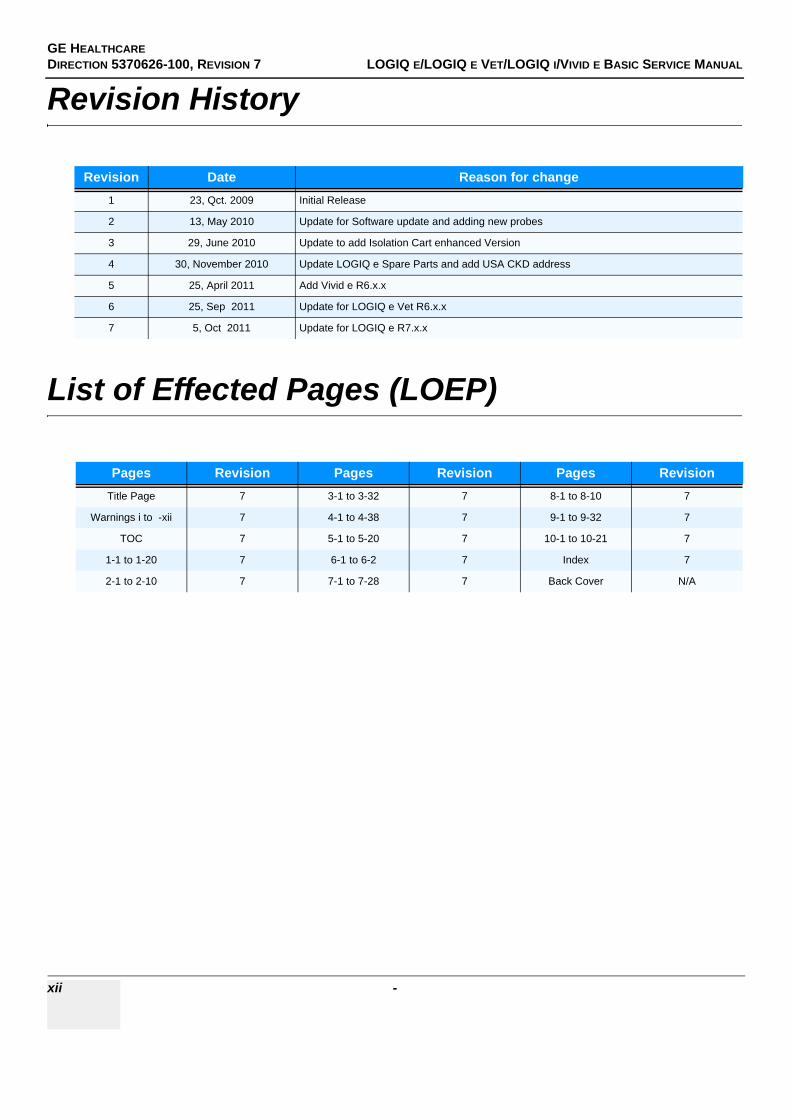
Revision History
List of Effected Pages (LOEP)
Revision Date Reason for change1 23, Qct. 2009 Initial Release
2 13, May 2010 Update for Software update and adding new probes
3 29, June 2010 Update to add Isolation Cart enhanced Version
4 30, November 2010 Update LOGIQ e Spare Parts and add USA CKD address
5 25, April 2011 Add Vivid e R6.x.x
6 25, Sep 2011 Update for LOGIQ e Vet R6.x.x
7 5, Oct 2011 Update for LOGIQ e R7.x.x
Pages Revision Pages Revision Pages RevisionTitle Page 7 3-1 to 3-32 7 8-1 to 8-10 7
Warnings i to -xii 7 4-1 to 4-38 7 9-1 to 9-32 7
TOC 7 5-1 to 5-20 7 10-1 to 10-21 7
1-1 to 1-20 7 6-1 to 6-2 7 Index 7
2-1 to 2-10 7 7-1 to 7-28 7 Back Cover N/A
GE HEALTHCARE
DIRECTION 5370626-100, REVISION 7 LOGIQ E/LOGIQ E VET/LOGIQ I/VIVID E BASIC SERVICE MANUAL
1 Table of Contents
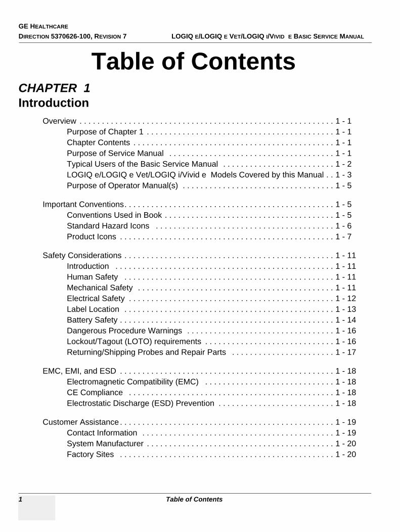
Table of ContentsCHAPTER 1Introduction
Overview . . . . . . . . . . . . . . . . . . . . . . . . . . . . . . . . . . . . . . . . . . . . . . . . . . . . . . . . . 1 - 1Purpose of Chapter 1 . . . . . . . . . . . . . . . . . . . . . . . . . . . . . . . . . . . . . . . . . . 1 - 1Chapter Contents . . . . . . . . . . . . . . . . . . . . . . . . . . . . . . . . . . . . . . . . . . . . . 1 - 1Purpose of Service Manual . . . . . . . . . . . . . . . . . . . . . . . . . . . . . . . . . . . . . 1 - 1Typical Users of the Basic Service Manual . . . . . . . . . . . . . . . . . . . . . . . . . 1 - 2LOGIQ e/LOGIQ e Vet/LOGIQ i/Vivid e Models Covered by this Manual . . 1 - 3Purpose of Operator Manual(s) . . . . . . . . . . . . . . . . . . . . . . . . . . . . . . . . . . 1 - 5
Important Conventions. . . . . . . . . . . . . . . . . . . . . . . . . . . . . . . . . . . . . . . . . . . . . . . 1 - 5Conventions Used in Book . . . . . . . . . . . . . . . . . . . . . . . . . . . . . . . . . . . . . . 1 - 5Standard Hazard Icons . . . . . . . . . . . . . . . . . . . . . . . . . . . . . . . . . . . . . . . . 1 - 6Product Icons . . . . . . . . . . . . . . . . . . . . . . . . . . . . . . . . . . . . . . . . . . . . . . . . 1 - 7
Safety Considerations . . . . . . . . . . . . . . . . . . . . . . . . . . . . . . . . . . . . . . . . . . . . . . . 1 - 11Introduction . . . . . . . . . . . . . . . . . . . . . . . . . . . . . . . . . . . . . . . . . . . . . . . . . 1 - 11Human Safety . . . . . . . . . . . . . . . . . . . . . . . . . . . . . . . . . . . . . . . . . . . . . . . 1 - 11Mechanical Safety . . . . . . . . . . . . . . . . . . . . . . . . . . . . . . . . . . . . . . . . . . . . 1 - 11Electrical Safety . . . . . . . . . . . . . . . . . . . . . . . . . . . . . . . . . . . . . . . . . . . . . . 1 - 12Label Location . . . . . . . . . . . . . . . . . . . . . . . . . . . . . . . . . . . . . . . . . . . . . . . 1 - 13Battery Safety . . . . . . . . . . . . . . . . . . . . . . . . . . . . . . . . . . . . . . . . . . . . . . . . 1 - 14Dangerous Procedure Warnings . . . . . . . . . . . . . . . . . . . . . . . . . . . . . . . . . 1 - 16Lockout/Tagout (LOTO) requirements . . . . . . . . . . . . . . . . . . . . . . . . . . . . . 1 - 16Returning/Shipping Probes and Repair Parts . . . . . . . . . . . . . . . . . . . . . . . 1 - 17
EMC, EMI, and ESD . . . . . . . . . . . . . . . . . . . . . . . . . . . . . . . . . . . . . . . . . . . . . . . . 1 - 18Electromagnetic Compatibility (EMC) . . . . . . . . . . . . . . . . . . . . . . . . . . . . . 1 - 18CE Compliance . . . . . . . . . . . . . . . . . . . . . . . . . . . . . . . . . . . . . . . . . . . . . . 1 - 18Electrostatic Discharge (ESD) Prevention . . . . . . . . . . . . . . . . . . . . . . . . . . 1 - 18
Customer Assistance . . . . . . . . . . . . . . . . . . . . . . . . . . . . . . . . . . . . . . . . . . . . . . . . 1 - 19Contact Information . . . . . . . . . . . . . . . . . . . . . . . . . . . . . . . . . . . . . . . . . . . 1 - 19System Manufacturer . . . . . . . . . . . . . . . . . . . . . . . . . . . . . . . . . . . . . . . . . . 1 - 20Factory Sites . . . . . . . . . . . . . . . . . . . . . . . . . . . . . . . . . . . . . . . . . . . . . . . . 1 - 20
GE HEALTHCAREDIRECTION 5370626-100, REVISION 7 LOGIQ E/LOGIQ E VET/LOGIQ I/VIVID E BASIC SERVICE MANUAL
Table of Contents 2
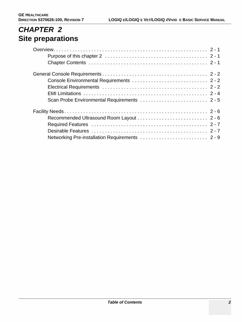
CHAPTER 2Site preparations
Overview. . . . . . . . . . . . . . . . . . . . . . . . . . . . . . . . . . . . . . . . . . . . . . . . . . . . . . . . . 2 - 1Purpose of this chapter 2 . . . . . . . . . . . . . . . . . . . . . . . . . . . . . . . . . . . . . . 2 - 1Chapter Contents . . . . . . . . . . . . . . . . . . . . . . . . . . . . . . . . . . . . . . . . . . . . 2 - 1
General Console Requirements . . . . . . . . . . . . . . . . . . . . . . . . . . . . . . . . . . . . . . . 2 - 2Console Environmental Requirements . . . . . . . . . . . . . . . . . . . . . . . . . . . . 2 - 2Electrical Requirements . . . . . . . . . . . . . . . . . . . . . . . . . . . . . . . . . . . . . . . 2 - 2EMI Limitations . . . . . . . . . . . . . . . . . . . . . . . . . . . . . . . . . . . . . . . . . . . . . . 2 - 4Scan Probe Environmental Requirements . . . . . . . . . . . . . . . . . . . . . . . . . 2 - 5
Facility Needs . . . . . . . . . . . . . . . . . . . . . . . . . . . . . . . . . . . . . . . . . . . . . . . . . . . . . 2 - 6Recommended Ultrasound Room Layout . . . . . . . . . . . . . . . . . . . . . . . . . . 2 - 6Required Features . . . . . . . . . . . . . . . . . . . . . . . . . . . . . . . . . . . . . . . . . . . 2 - 7Desirable Features . . . . . . . . . . . . . . . . . . . . . . . . . . . . . . . . . . . . . . . . . . . 2 - 7Networking Pre-installation Requirements . . . . . . . . . . . . . . . . . . . . . . . . . 2 - 9
GE HEALTHCAREDIRECTION 5370626-100, REVISION 7 LOGIQ E/LOGIQ E VET/LOGIQ I/VIVID E BASIC SERVICE MANUAL
Table of Contents 3
CHAPTER 3System Setup
Overview. . . . . . . . . . . . . . . . . . . . . . . . . . . . . . . . . . . . . . . . . . . . . . . . . . . . . . . . . 3 - 1Purpose of Chapter 3 . . . . . . . . . . . . . . . . . . . . . . . . . . . . . . . . . . . . . . . . . 3 - 1Average Installation Time . . . . . . . . . . . . . . . . . . . . . . . . . . . . . . . . . . . . . . 3 - 2Installation Warnings . . . . . . . . . . . . . . . . . . . . . . . . . . . . . . . . . . . . . . . . . 3 - 3Safety Reminders . . . . . . . . . . . . . . . . . . . . . . . . . . . . . . . . . . . . . . . . . . . . 3 - 3
Receiving and Unpacking the Equipment. . . . . . . . . . . . . . . . . . . . . . . . . . . . . . . . 3 - 4Moving into Position . . . . . . . . . . . . . . . . . . . . . . . . . . . . . . . . . . . . . . . . . . 3 - 7
Packing the Equipment. . . . . . . . . . . . . . . . . . . . . . . . . . . . . . . . . . . . . . . . . . . . . . 3 - 7
Preparing for Installation. . . . . . . . . . . . . . . . . . . . . . . . . . . . . . . . . . . . . . . . . . . . . 3 - 8Verify Customer Order . . . . . . . . . . . . . . . . . . . . . . . . . . . . . . . . . . . . . . . . 3 - 8Physical Inspection . . . . . . . . . . . . . . . . . . . . . . . . . . . . . . . . . . . . . . . . . . . 3 - 8EMI Protection . . . . . . . . . . . . . . . . . . . . . . . . . . . . . . . . . . . . . . . . . . . . . . 3 - 8
Completing the Installation . . . . . . . . . . . . . . . . . . . . . . . . . . . . . . . . . . . . . . . . . . . 3 - 9Power On / Boot Up . . . . . . . . . . . . . . . . . . . . . . . . . . . . . . . . . . . . . . . . . . 3 - 9Power Off/ Shutdown . . . . . . . . . . . . . . . . . . . . . . . . . . . . . . . . . . . . . . . . . 3 - 10Transducer Connection . . . . . . . . . . . . . . . . . . . . . . . . . . . . . . . . . . . . . . . 3 - 11
System Configuration . . . . . . . . . . . . . . . . . . . . . . . . . . . . . . . . . . . . . . . . . . . . . . . 3 - 12System Specifications . . . . . . . . . . . . . . . . . . . . . . . . . . . . . . . . . . . . . . . . . 3 - 12Electrical Specifications . . . . . . . . . . . . . . . . . . . . . . . . . . . . . . . . . . . . . . . 3 - 12Approved peripherals . . . . . . . . . . . . . . . . . . . . . . . . . . . . . . . . . . . . . . . . . 3 - 13Connecting Cables . . . . . . . . . . . . . . . . . . . . . . . . . . . . . . . . . . . . . . . . . . . 3 - 14Peripherals/Accessories Connector Panel . . . . . . . . . . . . . . . . . . . . . . . . . 3 - 14Available Probes . . . . . . . . . . . . . . . . . . . . . . . . . . . . . . . . . . . . . . . . . . . . . 3 - 25
Software/Option Configuration . . . . . . . . . . . . . . . . . . . . . . . . . . . . . . . . . . . . . . . . 3 - 27
Connectivity Installation Worksheet . . . . . . . . . . . . . . . . . . . . . . . . . . . . . . . . . . . . 3 - 28
Loading Base Image Software . . . . . . . . . . . . . . . . . . . . . . . . . . . . . . . . . . . . . . . . 3 - 29Software Version check out . . . . . . . . . . . . . . . . . . . . . . . . . . . . . . . . . . . . . . . . . . 3 - 30
Functional Check-out . . . . . . . . . . . . . . . . . . . . . . . . . . . . . . . . . . . . . . . . . 3 - 30
Paperwork . . . . . . . . . . . . . . . . . . . . . . . . . . . . . . . . . . . . . . . . . . . . . . . . . . . . . . . 3 - 31Product Locator Installation . . . . . . . . . . . . . . . . . . . . . . . . . . . . . . . . . . . . 3 - 31User Manual(s) . . . . . . . . . . . . . . . . . . . . . . . . . . . . . . . . . . . . . . . . . . . . . . 3 - 31
GE HEALTHCAREDIRECTION 5370626-100, REVISION 7 LOGIQ E/LOGIQ E VET/LOGIQ I/VIVID E BASIC SERVICE MANUAL
Table of Contents 4
CHAPTER 4Functional Checks
Overview. . . . . . . . . . . . . . . . . . . . . . . . . . . . . . . . . . . . . . . . . . . . . . . . . . . . . . . . . 4 - 1Purpose for Chapter 4 . . . . . . . . . . . . . . . . . . . . . . . . . . . . . . . . . . . . . . . . 4 - 1
Required Equipment. . . . . . . . . . . . . . . . . . . . . . . . . . . . . . . . . . . . . . . . . . . . . . . . 4 - 1
General Procedure . . . . . . . . . . . . . . . . . . . . . . . . . . . . . . . . . . . . . . . . . . . . . . . . . 4 - 2Power On/Boot Up . . . . . . . . . . . . . . . . . . . . . . . . . . . . . . . . . . . . . . . . . . . 4 - 2Power Off/ Shutdown . . . . . . . . . . . . . . . . . . . . . . . . . . . . . . . . . . . . . . . . . 4 - 3Archiving and Loading Presets . . . . . . . . . . . . . . . . . . . . . . . . . . . . . . . . . . 4 - 5Adjusting the Display Monitor . . . . . . . . . . . . . . . . . . . . . . . . . . . . . . . . . . . 4 - 6Lockout/Tagout (LOTO) requirements . . . . . . . . . . . . . . . . . . . . . . . . . . . . 4 - 6System Features . . . . . . . . . . . . . . . . . . . . . . . . . . . . . . . . . . . . . . . . . . . . . 4 - 7B Mode Checks . . . . . . . . . . . . . . . . . . . . . . . . . . . . . . . . . . . . . . . . . . . . . 4 - 10M Mode Controls . . . . . . . . . . . . . . . . . . . . . . . . . . . . . . . . . . . . . . . . . . . . 4 - 13Color Flow Mode Checks . . . . . . . . . . . . . . . . . . . . . . . . . . . . . . . . . . . . . . 4 - 16Doppler Mode Checks . . . . . . . . . . . . . . . . . . . . . . . . . . . . . . . . . . . . . . . . 4 - 20CWD Functional Check . . . . . . . . . . . . . . . . . . . . . . . . . . . . . . . . . . . . . . . 4 - 24Basic Measurements . . . . . . . . . . . . . . . . . . . . . . . . . . . . . . . . . . . . . . . . . 4 - 25Probe/Connectors Usage . . . . . . . . . . . . . . . . . . . . . . . . . . . . . . . . . . . . . . 4 - 25Using Cine . . . . . . . . . . . . . . . . . . . . . . . . . . . . . . . . . . . . . . . . . . . . . . . . . 4 - 26Image Management (QG) . . . . . . . . . . . . . . . . . . . . . . . . . . . . . . . . . . . . . . 4 - 27Backup and Restore Database, Preset Configurations and Images . . . . . 4 - 28
Software Configuration Checks . . . . . . . . . . . . . . . . . . . . . . . . . . . . . . . . . . . . . . . 4 - 37
Peripheral Checks . . . . . . . . . . . . . . . . . . . . . . . . . . . . . . . . . . . . . . . . . . . . . . . . . 4 - 37
GE HEALTHCAREDIRECTION 5370626-100, REVISION 7 LOGIQ E/LOGIQ E VET/LOGIQ I/VIVID E BASIC SERVICE MANUAL
Table of Contents 5
CHAPTER 5Components and Functions (Theory)
Overview. . . . . . . . . . . . . . . . . . . . . . . . . . . . . . . . . . . . . . . . . . . . . . . . . . . . . . . . . 5 - 1
Block Diagrams and Theory . . . . . . . . . . . . . . . . . . . . . . . . . . . . . . . . . . . . . . . . . . 5 - 2Block Diagram . . . . . . . . . . . . . . . . . . . . . . . . . . . . . . . . . . . . . . . . . . . . . . 5 - 2General Information . . . . . . . . . . . . . . . . . . . . . . . . . . . . . . . . . . . . . . . . . . 5 - 3External I/O . . . . . . . . . . . . . . . . . . . . . . . . . . . . . . . . . . . . . . . . . . . . . . . . . 5 - 4Peripherals . . . . . . . . . . . . . . . . . . . . . . . . . . . . . . . . . . . . . . . . . . . . . . . . . 5 - 4Wiring . . . . . . . . . . . . . . . . . . . . . . . . . . . . . . . . . . . . . . . . . . . . . . . . . . . . . 5 - 5
Power Diagrams . . . . . . . . . . . . . . . . . . . . . . . . . . . . . . . . . . . . . . . . . . . . . . . . . . . 5 - 6Overview . . . . . . . . . . . . . . . . . . . . . . . . . . . . . . . . . . . . . . . . . . . . . . . . . . . 5 - 6AC Power . . . . . . . . . . . . . . . . . . . . . . . . . . . . . . . . . . . . . . . . . . . . . . . . . . 5 - 6Battery charging . . . . . . . . . . . . . . . . . . . . . . . . . . . . . . . . . . . . . . . . . . . . . 5 - 7Air Flow Distribution . . . . . . . . . . . . . . . . . . . . . . . . . . . . . . . . . . . . . . . . . . 5 - 8Fans . . . . . . . . . . . . . . . . . . . . . . . . . . . . . . . . . . . . . . . . . . . . . . . . . . . . . . 5 - 9
Common Service Platform . . . . . . . . . . . . . . . . . . . . . . . . . . . . . . . . . . . . . . . . . . . 5 - 10Introduction . . . . . . . . . . . . . . . . . . . . . . . . . . . . . . . . . . . . . . . . . . . . . . . . . 5 - 10Global Service User Interface (GSUI) . . . . . . . . . . . . . . . . . . . . . . . . . . . . . 5 - 10Service Home Page . . . . . . . . . . . . . . . . . . . . . . . . . . . . . . . . . . . . . . . . . . 5 - 12Error Logs Tab . . . . . . . . . . . . . . . . . . . . . . . . . . . . . . . . . . . . . . . . . . . . . . 5 - 13Diagnostics . . . . . . . . . . . . . . . . . . . . . . . . . . . . . . . . . . . . . . . . . . . . . . . . . 5 - 17Image Quality . . . . . . . . . . . . . . . . . . . . . . . . . . . . . . . . . . . . . . . . . . . . . . . 5 - 18Calibration . . . . . . . . . . . . . . . . . . . . . . . . . . . . . . . . . . . . . . . . . . . . . . . . . . 5 - 18Configuration . . . . . . . . . . . . . . . . . . . . . . . . . . . . . . . . . . . . . . . . . . . . . . . 5 - 19Utilities . . . . . . . . . . . . . . . . . . . . . . . . . . . . . . . . . . . . . . . . . . . . . . . . . . . . 5 - 19Replacement . . . . . . . . . . . . . . . . . . . . . . . . . . . . . . . . . . . . . . . . . . . . . . . . 5 - 20PM . . . . . . . . . . . . . . . . . . . . . . . . . . . . . . . . . . . . . . . . . . . . . . . . . . . . . . . 5 - 20
GE HEALTHCAREDIRECTION 5370626-100, REVISION 7 LOGIQ E/LOGIQ E VET/LOGIQ I/VIVID E BASIC SERVICE MANUAL
Table of Contents 6
CHAPTER 6Service Adjustments
Overview. . . . . . . . . . . . . . . . . . . . . . . . . . . . . . . . . . . . . . . . . . . . . . . . . . . . . . . . . 6 - 1Purpose of this chapter 6 . . . . . . . . . . . . . . . . . . . . . . . . . . . . . . . . . . . . . . 6 - 1
Monitor Adjustments. . . . . . . . . . . . . . . . . . . . . . . . . . . . . . . . . . . . . . . . . . . . . . . . 6 - 2Adjustments Procedures . . . . . . . . . . . . . . . . . . . . . . . . . . . . . . . . . . . . . . . 6 - 2
GE HEALTHCAREDIRECTION 5370626-100, REVISION 7 LOGIQ E/LOGIQ E VET/LOGIQ I/VIVID E BASIC SERVICE MANUAL
Table of Contents 7
CHAPTER 7Diagnostics/Troubleshooting
Overview. . . . . . . . . . . . . . . . . . . . . . . . . . . . . . . . . . . . . . . . . . . . . . . . . . . . . . . . . 7 - 1Purpose of Chapter 7 . . . . . . . . . . . . . . . . . . . . . . . . . . . . . . . . . . . . . . . . . 7 - 1
Gathering Trouble Data . . . . . . . . . . . . . . . . . . . . . . . . . . . . . . . . . . . . . . . . . . . . . 7 - 2Overview . . . . . . . . . . . . . . . . . . . . . . . . . . . . . . . . . . . . . . . . . . . . . . . . . . . 7 - 2Collect Vital System Information . . . . . . . . . . . . . . . . . . . . . . . . . . . . . . . . . 7 - 2Collect a Trouble Image with Logs . . . . . . . . . . . . . . . . . . . . . . . . . . . . . . . 7 - 3
USB Quick Save. . . . . . . . . . . . . . . . . . . . . . . . . . . . . . . . . . . . . . . . . . . . . . . . . . . 7 - 4Overview . . . . . . . . . . . . . . . . . . . . . . . . . . . . . . . . . . . . . . . . . . . . . . . . . . . 7 - 4Check and Record the P3 Key Function . . . . . . . . . . . . . . . . . . . . . . . . . . . 7 - 4Setting the P3 Key to USB Quick Save . . . . . . . . . . . . . . . . . . . . . . . . . . . 7 - 5
Screen Captures. . . . . . . . . . . . . . . . . . . . . . . . . . . . . . . . . . . . . . . . . . . . . . . . . . . 7 - 6Check and Record the P1 Key Function . . . . . . . . . . . . . . . . . . . . . . . . . . . 7 - 6Setting the P1 Key to Screen Capture . . . . . . . . . . . . . . . . . . . . . . . . . . . . 7 - 6Capturing a Screen . . . . . . . . . . . . . . . . . . . . . . . . . . . . . . . . . . . . . . . . . . . 7 - 6Reset the P1 Key to Customer’s Functionality . . . . . . . . . . . . . . . . . . . . . . 7 - 8
Global Service User Interface (GSUI) . . . . . . . . . . . . . . . . . . . . . . . . . . . . . . . . . . 7 - 9Enter global service user interface . . . . . . . . . . . . . . . . . . . . . . . . . . . . . . . 7 - 9Active Diagnostic Function . . . . . . . . . . . . . . . . . . . . . . . . . . . . . . . . . . . . . 7 - 10Control Frame . . . . . . . . . . . . . . . . . . . . . . . . . . . . . . . . . . . . . . . . . . . . . . . 7 - 10
Common Diagnostics . . . . . . . . . . . . . . . . . . . . . . . . . . . . . . . . . . . . . . . . . . . . . . . 7 - 12Utilities . . . . . . . . . . . . . . . . . . . . . . . . . . . . . . . . . . . . . . . . . . . . . . . . . . . . 7 - 12PC Diagnostics (Non-Interactive Tests) . . . . . . . . . . . . . . . . . . . . . . . . . . . 7 - 13PC Diagnostics (Interactive Tests) . . . . . . . . . . . . . . . . . . . . . . . . . . . . . . . 7 - 14Restart the system after diagnostics . . . . . . . . . . . . . . . . . . . . . . . . . . . . . . 7 - 14
Network and Insite II Configuration . . . . . . . . . . . . . . . . . . . . . . . . . . . . . . . . . . . . 7 - 15Network Configuration . . . . . . . . . . . . . . . . . . . . . . . . . . . . . . . . . . . . . . . . 7 - 15Insite II Configuration . . . . . . . . . . . . . . . . . . . . . . . . . . . . . . . . . . . . . . . . . 7 - 19Insite II Configuration (For LOGIQ e R6.x.x) . . . . . . . . . . . . . . . . . . . . . . . 7 - 24
GE HEALTHCAREDIRECTION 5370626-100, REVISION 7 LOGIQ E/LOGIQ E VET/LOGIQ I/VIVID E BASIC SERVICE MANUAL
8 Table of Contents
CHAPTER 8Replacement Procedures
Overview . . . . . . . . . . . . . . . . . . . . . . . . . . . . . . . . . . . . . . . . . . . . . . . . . . . . . . . . . 8 - 1Purpose of Chapter 8 . . . . . . . . . . . . . . . . . . . . . . . . . . . . . . . . . . . . . . . . . . 8 - 1
Disassembly/Re-assembly of LOGIQ e/LOGIQ e Vet/LOGIQ i/Vivid e . . . . . . . . . 8 - 1Warning and Caution . . . . . . . . . . . . . . . . . . . . . . . . . . . . . . . . . . . . . . . . . . 8 - 1Handle Assy (FRU No. 313) . . . . . . . . . . . . . . . . . . . . . . . . . . . . . . . . . . . . . 8 - 2
Loading Base Image Software. . . . . . . . . . . . . . . . . . . . . . . . . . . . . . . . . . . . . . . . . 8 - 4Checks after FRU replacement (Debrief Guidelines). . . . . . . . . . . . . . . . . . . . . . . . 8 - 9
GE HEALTHCAREDIRECTION 5370626-100, REVISION 7 LOGIQ E/LOGIQ E VET/LOGIQ I/VIVID E BASIC SERVICE MANUAL
Table of Contents 9
CHAPTER 9Renewal Parts
Overview. . . . . . . . . . . . . . . . . . . . . . . . . . . . . . . . . . . . . . . . . . . . . . . . . . . . . . . . . 9 - 1Purpose of Chapter 9 . . . . . . . . . . . . . . . . . . . . . . . . . . . . . . . . . . . . . . . . . 9 - 1
List of Abbreviations . . . . . . . . . . . . . . . . . . . . . . . . . . . . . . . . . . . . . . . . . . . . . . . . 9 - 1Renewal Parts Lists . . . . . . . . . . . . . . . . . . . . . . . . . . . . . . . . . . . . . . . . . . . . . . . . 9 - 2
Equipment Models Covered in this Chapter . . . . . . . . . . . . . . . . . . . . . . . . 9 - 2Operator Console Assy . . . . . . . . . . . . . . . . . . . . . . . . . . . . . . . . . . . . . . . . . . . . . 9 - 3 LCD Assy . . . . . . . . . . . . . . . . . . . . . . . . . . . . . . . . . . . . . . . . . . . . . . . . . . . . . . . . 9 - 4Keyboard Assy . . . . . . . . . . . . . . . . . . . . . . . . . . . . . . . . . . . . . . . . . . . . . . . . . . . . 9 - 6Bottom Assy . . . . . . . . . . . . . . . . . . . . . . . . . . . . . . . . . . . . . . . . . . . . . . . . . . . . . . 9 - 9
Cables . . . . . . . . . . . . . . . . . . . . . . . . . . . . . . . . . . . . . . . . . . . . . . . . . . . . . . . . . . 9 - 14Isolation Cart Components . . . . . . . . . . . . . . . . . . . . . . . . . . . . . . . . . . . . . . . . . . . 9 - 15
Isolation Cart Enhanced Version Components. . . . . . . . . . . . . . . . . . . . . . . . . . . . 9 - 17
Accessories and Kits . . . . . . . . . . . . . . . . . . . . . . . . . . . . . . . . . . . . . . . . . . . . . . . 9 - 19Manuals . . . . . . . . . . . . . . . . . . . . . . . . . . . . . . . . . . . . . . . . . . . . . . . . . . . . . . . . . 9 - 24Probe . . . . . . . . . . . . . . . . . . . . . . . . . . . . . . . . . . . . . . . . . . . . . . . . . . . . . . . . . . . 9 - 29
GE HEALTHCAREDIRECTION 5370626-100, REVISION 7 LOGIQ E/LOGIQ E VET/LOGIQ I/VIVID E BASIC SERVICE MANUAL
10 Table of Contents
CHAPTER 10Care & Maintenance
Overview . . . . . . . . . . . . . . . . . . . . . . . . . . . . . . . . . . . . . . . . . . . . . . . . . . . . . . . . . 10 - 1
Periodic Maintenance Inspections . . . . . . . . . . . . . . . . . . . . . . . . . . . . . . . . 10 - 1Purpose of Chapter 10 . . . . . . . . . . . . . . . . . . . . . . . . . . . . . . . . . . . . . . . . . 10 - 1
Why do Maintenance . . . . . . . . . . . . . . . . . . . . . . . . . . . . . . . . . . . . . . . . . . . . . . . . 10 - 2Keeping Records . . . . . . . . . . . . . . . . . . . . . . . . . . . . . . . . . . . . . . . . . . . . . 10 - 2Quality Assurance . . . . . . . . . . . . . . . . . . . . . . . . . . . . . . . . . . . . . . . . . . . . 10 - 2
Maintenance Task Schedule . . . . . . . . . . . . . . . . . . . . . . . . . . . . . . . . . . . . . . . . . . 10 - 2How often should care & maintenance tasks be performed? . . . . . . . . . . . . 10 - 2
Tools Required. . . . . . . . . . . . . . . . . . . . . . . . . . . . . . . . . . . . . . . . . . . . . . . . . . . . . 10 - 4Special Tools, Supplies and Equipment . . . . . . . . . . . . . . . . . . . . . . . . . . . . 10 - 4
System Maintenance . . . . . . . . . . . . . . . . . . . . . . . . . . . . . . . . . . . . . . . . . . . . . . . . 10 - 5Preliminary Checks . . . . . . . . . . . . . . . . . . . . . . . . . . . . . . . . . . . . . . . . . . . 10 - 5Functional Checks (See Also Chapter 4) . . . . . . . . . . . . . . . . . . . . . . . . . . . 10 - 6Input Power . . . . . . . . . . . . . . . . . . . . . . . . . . . . . . . . . . . . . . . . . . . . . . . . . 10 - 7Cleaning . . . . . . . . . . . . . . . . . . . . . . . . . . . . . . . . . . . . . . . . . . . . . . . . . . . . 10 - 7Physical Inspection . . . . . . . . . . . . . . . . . . . . . . . . . . . . . . . . . . . . . . . . . . . 10 - 8Optional Diagnostic Checks . . . . . . . . . . . . . . . . . . . . . . . . . . . . . . . . . . . . . 10 - 9Probe Maintenance . . . . . . . . . . . . . . . . . . . . . . . . . . . . . . . . . . . . . . . . . . . 10 - 9Battery Performance Maintenance . . . . . . . . . . . . . . . . . . . . . . . . . . . . . . . . 10 - 10
Electrical Safety Tests . . . . . . . . . . . . . . . . . . . . . . . . . . . . . . . . . . . . . . . . . . . . . . . 10 - 11Safety Test Overview . . . . . . . . . . . . . . . . . . . . . . . . . . . . . . . . . . . . . . . . . . 10 - 11GEMS Leakage Current Limits . . . . . . . . . . . . . . . . . . . . . . . . . . . . . . . . . . 10 - 12Outlet Test - Wiring Arrangement . . . . . . . . . . . . . . . . . . . . . . . . . . . . . . . . 10 - 13Chassis Leakage Current Test . . . . . . . . . . . . . . . . . . . . . . . . . . . . . . . . . . . 10 - 14Probe Leakage Current Test . . . . . . . . . . . . . . . . . . . . . . . . . . . . . . . . . . . . 10 - 16
When There's Too Much Leakage Current... . . . . . . . . . . . . . . . . . . . . . . . . . . . . . . 10 - 19
GE HEALTHCARE DIRECTION 5370626-100, REVISION 7 LOGIQ E/LOGIQ E VET/LOGIQ I/VIVID E BASIC SERVICE MANUAL
Chapter 1 Introduction 1-1
Chapter 1Introduction
Section 1-1Overview
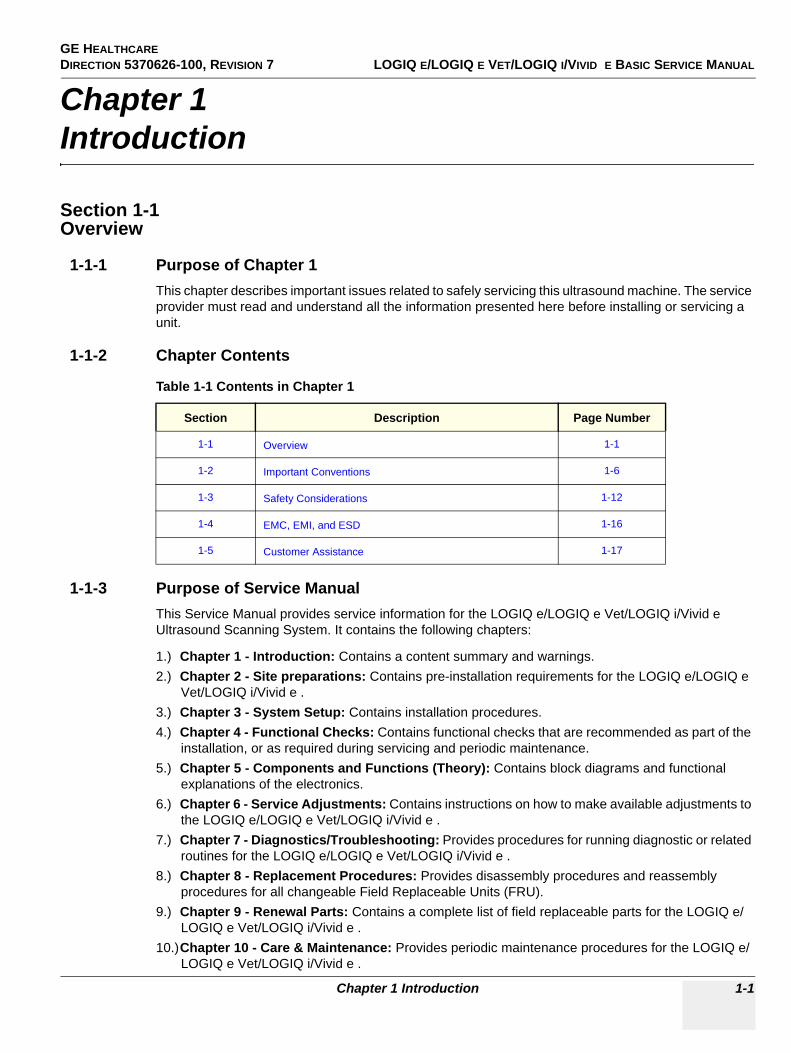
1-1-1 Purpose of Chapter 1This chapter describes important issues related to safely servicing this ultrasound machine. The service provider must read and understand all the information presented here before installing or servicing a unit.
1-1-2 Chapter Contents
1-1-3 Purpose of Service ManualThis Service Manual provides service information for the LOGIQ e/LOGIQ e Vet/LOGIQ i/Vivid e Ultrasound Scanning System. It contains the following chapters:
1.) Chapter 1 - Introduction: Contains a content summary and warnings.2.) Chapter 2 - Site preparations: Contains pre-installation requirements for the LOGIQ e/LOGIQ e
Vet/LOGIQ i/Vivid e .3.) Chapter 3 - System Setup: Contains installation procedures.4.) Chapter 4 - Functional Checks: Contains functional checks that are recommended as part of the
installation, or as required during servicing and periodic maintenance.5.) Chapter 5 - Components and Functions (Theory): Contains block diagrams and functional
explanations of the electronics.6.) Chapter 6 - Service Adjustments: Contains instructions on how to make available adjustments to
the LOGIQ e/LOGIQ e Vet/LOGIQ i/Vivid e .7.) Chapter 7 - Diagnostics/Troubleshooting: Provides procedures for running diagnostic or related
routines for the LOGIQ e/LOGIQ e Vet/LOGIQ i/Vivid e .8.) Chapter 8 - Replacement Procedures: Provides disassembly procedures and reassembly
procedures for all changeable Field Replaceable Units (FRU).9.) Chapter 9 - Renewal Parts: Contains a complete list of field replaceable parts for the LOGIQ e/
LOGIQ e Vet/LOGIQ i/Vivid e .10.)Chapter 10 - Care & Maintenance: Provides periodic maintenance procedures for the LOGIQ e/
LOGIQ e Vet/LOGIQ i/Vivid e .
Table 1-1 Contents in Chapter 1
Section Description Page Number
1-1 Overview 1-1
1-2 Important Conventions 1-6
1-3 Safety Considerations 1-12
1-4 EMC, EMI, and ESD 1-16
1-5 Customer Assistance 1-17
GE HEALTHCAREDIRECTION 5370626-100, REVISION 7 LOGIQ E/LOGIQ E VET/LOGIQ I/VIVID E BASIC SERVICE MANUAL
1-2 Section 1-1 - Overview
1-1-4 Typical Users of the Basic Service Manual• Service Personnel (installation, maintenance, etc.).• Hospital’s Service Personnel• Contractors (Some parts of Chapter 2 - Site Preparations)
GE HEALTHCARE DIRECTION 5370626-100, REVISION 7 LOGIQ E/LOGIQ E VET/LOGIQ I/VIVID E BASIC SERVICE MANUAL
Chapter 1 Introduction 1-3
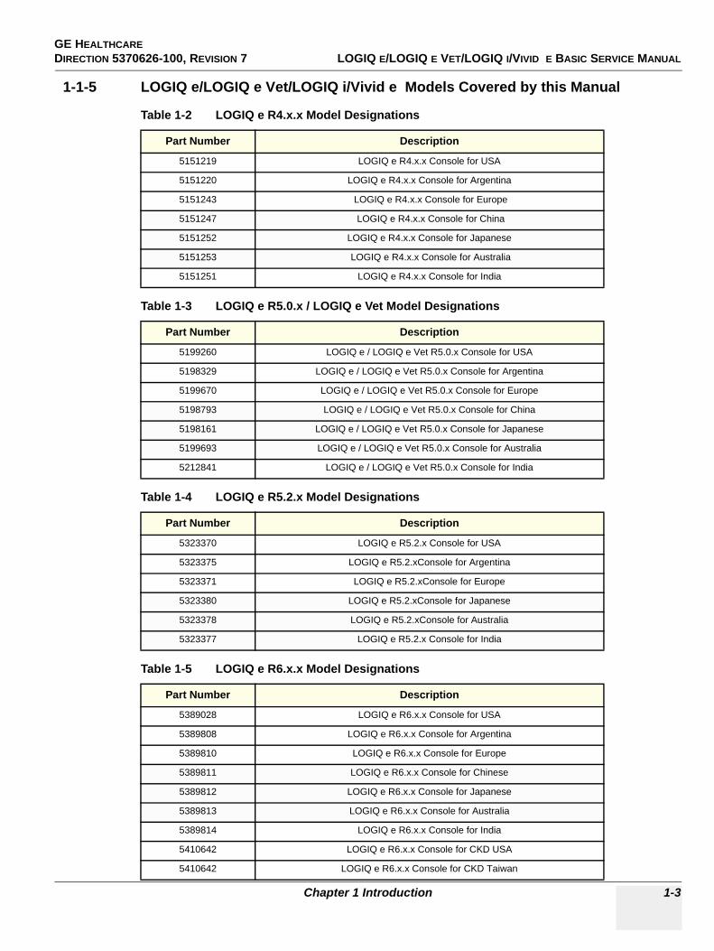
1-1-5 LOGIQ e/LOGIQ e Vet/LOGIQ i/Vivid e Models Covered by this Manual
Table 1-2 LOGIQ e R4.x.x Model Designations
Part Number Description
5151219 LOGIQ e R4.x.x Console for USA
5151220 LOGIQ e R4.x.x Console for Argentina
5151243 LOGIQ e R4.x.x Console for Europe
5151247 LOGIQ e R4.x.x Console for China
5151252 LOGIQ e R4.x.x Console for Japanese
5151253 LOGIQ e R4.x.x Console for Australia
5151251 LOGIQ e R4.x.x Console for India
Table 1-3 LOGIQ e R5.0.x / LOGIQ e Vet Model Designations
Part Number Description
5199260 LOGIQ e / LOGIQ e Vet R5.0.x Console for USA
5198329 LOGIQ e / LOGIQ e Vet R5.0.x Console for Argentina
5199670 LOGIQ e / LOGIQ e Vet R5.0.x Console for Europe
5198793 LOGIQ e / LOGIQ e Vet R5.0.x Console for China
5198161 LOGIQ e / LOGIQ e Vet R5.0.x Console for Japanese
5199693 LOGIQ e / LOGIQ e Vet R5.0.x Console for Australia
5212841 LOGIQ e / LOGIQ e Vet R5.0.x Console for India
Table 1-4 LOGIQ e R5.2.x Model Designations
Part Number Description
5323370 LOGIQ e R5.2.x Console for USA
5323375 LOGIQ e R5.2.xConsole for Argentina
5323371 LOGIQ e R5.2.xConsole for Europe
5323380 LOGIQ e R5.2.xConsole for Japanese
5323378 LOGIQ e R5.2.xConsole for Australia
5323377 LOGIQ e R5.2.x Console for India
Table 1-5 LOGIQ e R6.x.x Model Designations
Part Number Description
5389028 LOGIQ e R6.x.x Console for USA
5389808 LOGIQ e R6.x.x Console for Argentina
5389810 LOGIQ e R6.x.x Console for Europe
5389811 LOGIQ e R6.x.x Console for Chinese
5389812 LOGIQ e R6.x.x Console for Japanese
5389813 LOGIQ e R6.x.x Console for Australia
5389814 LOGIQ e R6.x.x Console for India
5410642 LOGIQ e R6.x.x Console for CKD USA
5410642 LOGIQ e R6.x.x Console for CKD Taiwan
GE HEALTHCAREDIRECTION 5370626-100, REVISION 7 LOGIQ E/LOGIQ E VET/LOGIQ I/VIVID E BASIC SERVICE MANUAL
1-4 Section 1-1 - Overview
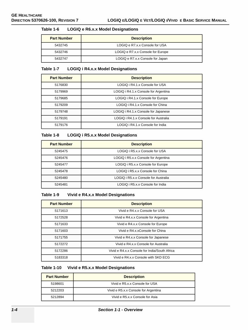
Table 1-6 LOGIQ e R6.x.x Model Designations
Part Number Description
5432745 LOGIQ e R7.x.x Console for USA
5432746 LOGIQ e R7.x.x Console for Europe
5432747 LOGIQ e R7.x.x Console for Japan
Table 1-7 LOGIQ i R4.x.x Model Designations
Part Number Description
5176830 LOGIQ i R4.1.x Console for USA
5179969 LOGIQ i R4.1.x Console for Argentina
5179685 LOGIQ i R4.1.x Console for Europe
5179209 LOGIQ i R4.1.x Console for China
5179748 LOGIQ i R4.1.x Console for Japanese
5179191 LOGIQ i R4.1.x Console for Australia
5179176 LOGIQ i R4.1.x Console for India
Table 1-8 LOGIQ i R5.x.x Model Designations
Part Number Description
5245475 LOGIQ i R5.x.x Console for USA
5245476 LOGIQ i R5.x.x Console for Argentina
5245477 LOGIQ i R5.x.x Console for Europe
5245478 LOGIQ i R5.x.x Console for China
5245480 LOGIQ i R5.x.x Console for Australia
5245481 LOGIQ i R5.x.x Console for India
Table 1-9 Vivid e R4.x.x Model Designations
Part Number Description
5171613 Vivid e R4.x.x Console for USA
5172528 Vivid e R4.x.x Console for Argentina
5171633 Vivid e R4.x.x Console for Europe
5171603 Vivid e R4.x.xConsole for China
5171755 Vivid e R4.x.x Console for Japanese
5172272 Vivid e R4.x.x Console for Australia
5172286 Vivid e R4.x.x Console for India/South Africa
5183318 Vivid e R4.x.x Console with SKD ECG
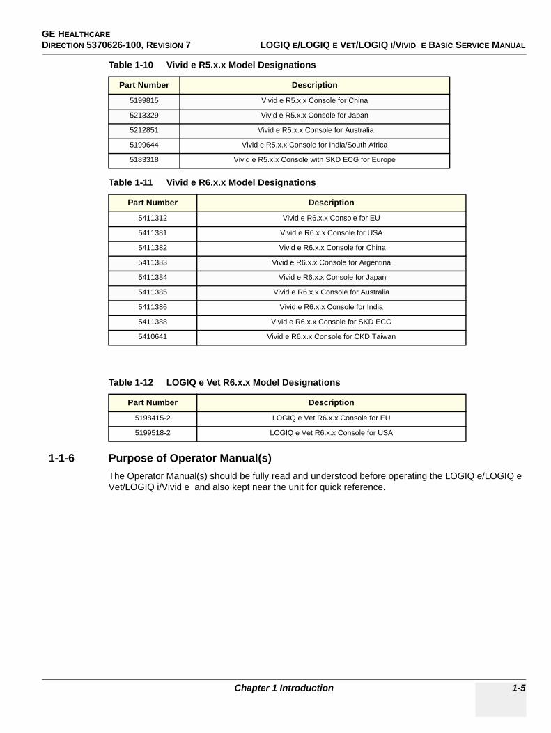
Table 1-10 Vivid e R5.x.x Model Designations
Part Number Description
5198601 Vivid e R5.x.x Console for USA
5212203 Vivid e R5.x.x Console for Argentina
5212894 Vivid e R5.x.x Console for Asia
GE HEALTHCARE DIRECTION 5370626-100, REVISION 7 LOGIQ E/LOGIQ E VET/LOGIQ I/VIVID E BASIC SERVICE MANUAL
Chapter 1 Introduction 1-5
1-1-6 Purpose of Operator Manual(s)The Operator Manual(s) should be fully read and understood before operating the LOGIQ e/LOGIQ e Vet/LOGIQ i/Vivid e and also kept near the unit for quick reference.
5199815 Vivid e R5.x.x Console for China
5213329 Vivid e R5.x.x Console for Japan
5212851 Vivid e R5.x.x Console for Australia
5199644 Vivid e R5.x.x Console for India/South Africa
5183318 Vivid e R5.x.x Console with SKD ECG for Europe
Table 1-11 Vivid e R6.x.x Model Designations
Part Number Description
5411312 Vivid e R6.x.x Console for EU
5411381 Vivid e R6.x.x Console for USA
5411382 Vivid e R6.x.x Console for China
5411383 Vivid e R6.x.x Console for Argentina
5411384 Vivid e R6.x.x Console for Japan
5411385 Vivid e R6.x.x Console for Australia
5411386 Vivid e R6.x.x Console for India
5411388 Vivid e R6.x.x Console for SKD ECG
5410641 Vivid e R6.x.x Console for CKD Taiwan
Table 1-12 LOGIQ e Vet R6.x.x Model Designations
Part Number Description
5198415-2 LOGIQ e Vet R6.x.x Console for EU
5199518-2 LOGIQ e Vet R6.x.x Console for USA
Table 1-10 Vivid e R5.x.x Model Designations
Part Number Description
GE HEALTHCAREDIRECTION 5370626-100, REVISION 7 LOGIQ E/LOGIQ E VET/LOGIQ I/VIVID E BASIC SERVICE MANUAL
1-6 Section 1-2 - Important Conventions
Section 1-2Important Conventions
1-2-1 Conventions Used in BookIcons
Pictures, or icons, are used wherever they reinforce the printed message. The icons, labels and conventions used on the product and in the service information are described in this chapter.
Safety Precaution Messages
Various levels of safety precaution messages may be found on the equipment and in the service information. The different levels of concern are identified by a flag word that precedes the precautionary message. Known or potential hazards are labeled in one of following ways:
NOTE: Notes provide important information about an item or a procedure. Information contained in a NOTE can often save you time or effort.
DANGER DANGER IS USED TO INDICATE THE PRESENCE OF A HAZARD THAT WILL CAUSE SEVERE PERSONAL INJURY OR DEATH IF THE INSTRUCTIONS ARE IGNORED.
WARNINGWARNING WARNING IS USED TO INDICATE THE PRESENCE OF A HAZARD THAT CAN CAUSE SEVERE PERSONAL INJURY AND PROPERTY DAMAGE IF INSTRUCTIONS ARE IGNORED.
CAUTION Caution is used to indicate the presence of a hazard that will or can cause minor personal injury and property damage if instructions are ignored.
NOTICE Equipment Damage PossibleNotice is used when a hazard is present that can cause property damage but has absolutely no personal injury risk. Example: Disk drive will crash.
GE HEALTHCARE DIRECTION 5370626-100, REVISION 7 LOGIQ E/LOGIQ E VET/LOGIQ I/VIVID E BASIC SERVICE MANUAL
Chapter 1 Introduction 1-7
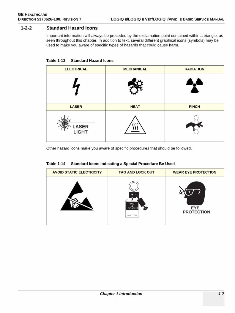
1-2-2 Standard Hazard IconsImportant information will always be preceded by the exclamation point contained within a triangle, as seen throughout this chapter. In addition to text, several different graphical icons (symbols) may be used to make you aware of specific types of hazards that could cause harm.
Other hazard icons make you aware of specific procedures that should be followed.
Table 1-13 Standard Hazard Icons
ELECTRICAL MECHANICAL RADIATION
LASER HEAT PINCH
Table 1-14 Standard Icons Indicating a Special Procedure Be Used
AVOID STATIC ELECTRICITY TAG AND LOCK OUT WEAR EYE PROTECTION
LASERLIGHT
Signed Date
TAG &
LOCKOUT EYEPROTECTION
GE HEALTHCAREDIRECTION 5370626-100, REVISION 7 LOGIQ E/LOGIQ E VET/LOGIQ I/VIVID E BASIC SERVICE MANUAL
1-8 Section 1-2 - Important Conventions
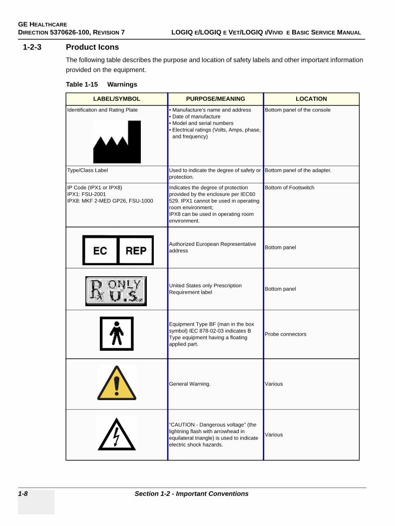
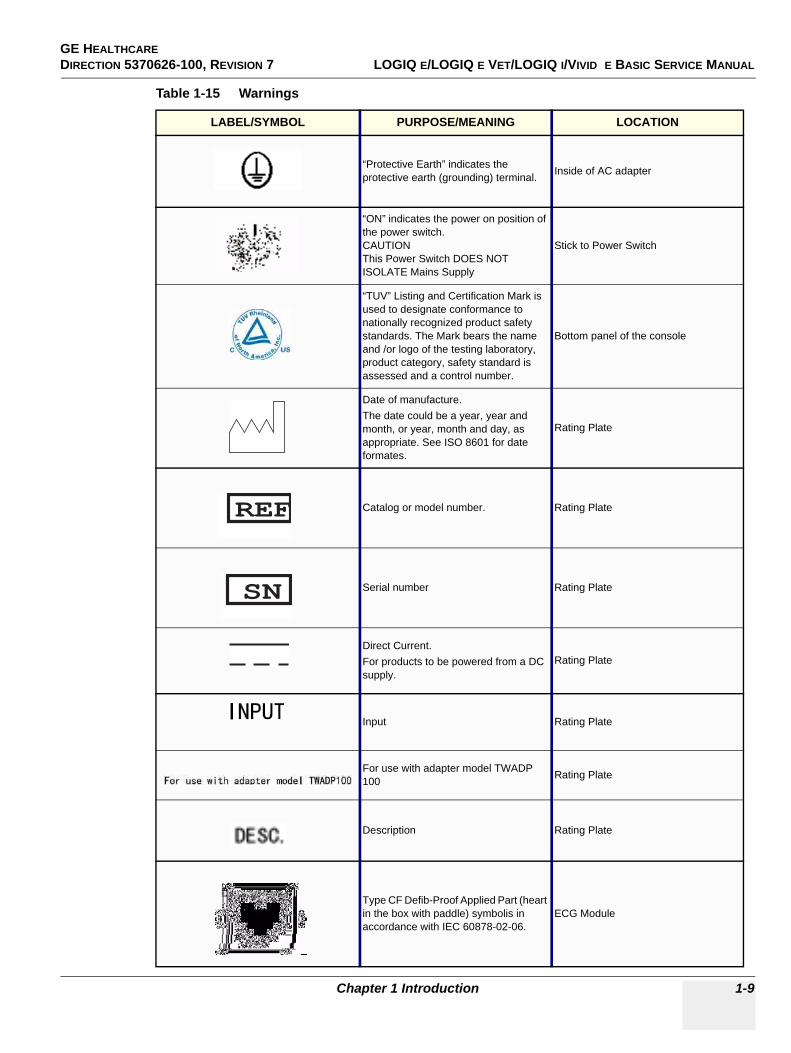
1-2-3 Product IconsThe following table describes the purpose and location of safety labels and other important information provided on the equipment.
Table 1-15 Warnings
LABEL/SYMBOL PURPOSE/MEANING LOCATION
Identification and Rating Plate • Manufacture’s name and address• Date of manufacture• Model and serial numbers• Electrical ratings (Volts, Amps, phase,
and frequency)
Bottom panel of the console
Type/Class Label Used to indicate the degree of safety or protection.
Bottom panel of the adapter.
IP Code (IPX1 or IPX8)IPX1: FSU-2001IPX8: MKF 2-MED GP26, FSU-1000
Indicates the degree of protection provided by the enclosure per IEC60 529. IPX1 cannot be used in operating room environment; IPX8 can be used in operating room environment.
Bottom of Footswitch
Authorized European Representative address Bottom panel
United States only Prescription Requirement label Bottom panel
Equipment Type BF (man in the box symbol) IEC 878-02-03 indicates B Type equipment having a floating applied part.
Probe connectors
General Warning. Various
“CAUTION - Dangerous voltage” (the lightning flash with arrowhead in equilateral triangle) is used to indicate electric shock hazards.
Various
GE HEALTHCARE DIRECTION 5370626-100, REVISION 7 LOGIQ E/LOGIQ E VET/LOGIQ I/VIVID E BASIC SERVICE MANUAL
Chapter 1 Introduction 1-9
“Protective Earth” indicates the protective earth (grounding) terminal. Inside of AC adapter
“ON” indicates the power on position of the power switch.CAUTIONThis Power Switch DOES NOT ISOLATE Mains Supply
Stick to Power Switch
“TUV” Listing and Certification Mark is used to designate conformance to nationally recognized product safety standards. The Mark bears the name and /or logo of the testing laboratory, product category, safety standard is assessed and a control number.
Bottom panel of the console
Date of manufacture.The date could be a year, year and month, or year, month and day, as appropriate. See ISO 8601 for date formates.
Rating Plate
Catalog or model number. Rating Plate
Serial number Rating Plate
Direct Current.For products to be powered from a DC supply.
Rating Plate
Input Rating Plate
For use with adapter model TWADP 100 Rating Plate
Description Rating Plate
Type CF Defib-Proof Applied Part (heart in the box with paddle) symbolis in accordance with IEC 60878-02-06.
ECG Module
Table 1-15 Warnings
LABEL/SYMBOL PURPOSE/MEANING LOCATION
REFREF
SNSN

GE HEALTHCAREDIRECTION 5370626-100, REVISION 7 LOGIQ E/LOGIQ E VET/LOGIQ I/VIVID E BASIC SERVICE MANUAL
1-10 Section 1-2 - Important Conventions
“Consult accompanying documents” is intended to alert the user to refer to the operator manual or other instructions when complete information cannot be provided on the label.
Various
Do not push the system. Rear of Docking Cart and rear of Isolation Cart.
This symbol indicates that the waste of electrical and electronic equipment must not be disposed as unsorted municipal waste and must be collected separately. Please contact an authorized representative of the manufacturer for information concerning the decommissioning of your equipment.
Rating Plate
When closing the LCD cover, use caution to avoid injuring hands or fingers as there is a closing mechanism which allows the LCD cover to automatically close.
Rating Plate
Indicates the product contains hazardous materials in excess of the limits established by Chinese standard SJ/T11363-2006 Requirements for Concentration Limits for Certain Hazardous Substances in Electronic Information Products. The number in the symbol is the Environment-friendly Use Period (EFUP), which indicates the period during which the toxic or hazardous substances or elements contained in electronic information products will not leak or mutate under normal operating conditions so that the use of such electronic information products will not result in any severe environmental pollution, any bodily injury or damage to any assets.
Rear panel, rating plate
This product consists of devices that may contain mercury, which must be recycled or disposed of in accordance with local, state, or country laws. (Within this system, the backlight lamps in the monitor display contain mercury.)
Bottom panel of the console
Table 1-15 Warnings
LABEL/SYMBOL PURPOSE/MEANING LOCATION
GE HEALTHCARE DIRECTION 5370626-100, REVISION 7 LOGIQ E/LOGIQ E VET/LOGIQ I/VIVID E BASIC SERVICE MANUAL
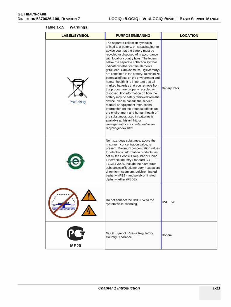
Chapter 1 Introduction 1-11
The separate collection symbol is affixed to a battery, or its packaging, to advise you that the battery must be recycled or disposed of in accordance with local or country laws. The letters below the separate collection symbol indicate whether certain elements (Pb=Lead, Cd=Cadmium, Hg=Mercury) are contained in the battery. To minimize potential effects on the environment and human health, it is important that all marked batteries that you remove from the product are properly recycled or disposed. For information on how the battery may be safely removed from the device, please consult the service manual or equipment instructions. Information on the potential effects on the environment and human health of the substances used in batteries is available at this url: http://www.gehealthcare.com/euen/weee-recycling/index.html
Battery Pack
No hazardous substance, above the maximum concentration value, is present. Maximum concentration values for electronic information products, as set by the People’s Republic of China Electronic Industry Standard SJ/T11364-2006, include the hazardous substances of lead, mercury, hexavalent chromium, cadmium, polybrominated biphenyl (PBB), and polybrominated diphenyl ether (PBDE).
Do not connect the DVD-RW to the system while scanning. DVD-RW
GOST Symbol. Russia Regulatory Country Clearance. Bottom
Table 1-15 Warnings
LABEL/SYMBOL PURPOSE/MEANING LOCATION
GE HEALTHCAREDIRECTION 5370626-100, REVISION 7 LOGIQ E/LOGIQ E VET/LOGIQ I/VIVID E BASIC SERVICE MANUAL
1-12 Section 1-3 - Safety Considerations
Section 1-3Safety Considerations
1-3-1 IntroductionThe following safety precautions must be observed during all phases of operation, service and repair of this equipment. Failure to comply with these precautions or with specific warnings elsewhere in this manual, violates safety standards of design, manufacture and intended use of the equipment.
1-3-2 Human SafetyOperating personnel must not remove the system covers. Servicing should be performed by authorized personnel only. Only personnel who have participated in a LOGIQ e/LOGIQ e Vet/LOGIQ i/Vivid e Training are authorized to service the equipment.
1-3-3 Mechanical Safety
NOTE: Special care should be taken when transporting the unit in a vehicle:
• Before transporting, place the system in its special storage case.• Ensure that the system is firmly secured while inside the vehicle.• Secure system with straps or as directed otherwise to prevent motion during transport.• Prevent vibration damage by driving cautiously. Avoid unpaved roads, excessive speeds, and
erratic stops or starts.
1-3-4 Electrical SafetyTo minimize shock hazard, the equipment chassis must be connected to an electrical ground. The system is equipped with a three-conductor AC power cable. This must be plugged into an approved electrical outlet with protective ground.
The power outlet used for this equipment should not be shared with other types of equipment.
Both the system power cable and the power connector meet international electrical standards.
1-3-5 Label LocationPlease refer to Basic User Manual for label location information.
WARNINGWARNING Ultrasound probes are highly sensitive medical instruments that can easily be damaged by improper handling. Use care when handling and protect from damage when not in use. Do not use a damaged or defective probe. Failure to follow these precautions can result in serious injury and equipment damage.
WARNINGWARNING Never use a probe that has fallen to the floor. Even if it looks ok, it may be damaged.
CAUTION The LOGIQ e/LOGIQ e Vet/LOGIQ i/Vivid e weights 4.6kg or more, depending on installed peripherals, when ready for use. To avoid possible injury and equipment damage:ALWAYS:• Use the handle to move the system.• Do not let the system strike walls or door frame.• Limit movement to a slow careful walk.

GE HEALTHCARE DIRECTION 5370626-100, REVISION 7 LOGIQ E/LOGIQ E VET/LOGIQ I/VIVID E BASIC SERVICE MANUAL
Chapter 1 Introduction 1-13
1-3-6 Battery SafetyTo avoid the risk of injury, follow the warning and cautions to make sure that the battery does not burst, ignite, or generate heat of fumes.
WARNINGWARNING • The battery has a safety device. Do not disassemble or alter the battery.• Charge and discharge the batteries only when the ambient temperature is between 10 and
40 C (50 F and 122 F).• Do not short-circuit the battery by directly connecting the negative terminals with metal
objects.• Do not heat the battery or discard it in a fire.• Do not expose the battery to temperature over 50° C (122° F). Keep it away from fire and other
heat sources.• Do not charge the battery near a heat source, such as a fire or heater.• Do not leave the battery in direct sunlight.• Do not drop packs from height to prevent them from possible malfunction damage.• Do not pierce the battery with a sharp object, hit it, or step on it.• Do not use a damaged battery.• Do not solder a battery.• Do not connect the battery to an electrical power outlet.• Do not contact PCM ( Power Control and Monitor, it’s a small board in the battery) directly
to prevent packs from ESD damage.• In case of longer non-use of the LOGIQ e/LOGIQ e Vet/LOGIQ i/Vivid e , please make sure the
battery is removed.
CAUTION To avoid the battery bursting, igniting, or fumes from the battery causing equipment damage, observe the following precautions:• Do not immerse the battery in water or allow it to get wet.• Do not put the battery into a microwave oven or pressurized container.• If the battery leaks or emits an odor, remove it from all possible flammable sources.• If the battery emits an odor or heat, is deformed or discolored, or in a way appears abnormal
during use, recharging or storage, immediately remove it and stop using it. If you have any questions about the battery, consult GE or your local representative.
• Short term (less than one month) storage of battery pack:• Store the battery in a temperature range between 0° C (32° F) and 50° C (122°F).
• Use only GE recognized batteries.• In case of the long term (3 months or more) storage:
• Store the battery in a temperature range of -20° C (-4° F) and 45° C (113°F).• When charging for the first time after long-term storage. Recover such packs to
original performance through repeating several cycles of full charging and discharging.
• When store packs for more than 6 months, charge at lease once charging require per 6 months to prevent leakage and deterioration in performance due to self-discharging.
• When the system isn't powered on continuously more than 6 months, in order to prevent leakage and deterioration in performance of CMOS battery, power on the system at least once per 6 months for more than 10 hours to have CMOS battery fully charged. Time and date need to be re-setup.
NOTICE The battery shall be shipped in about 30% charged state. Those packs have to be fully charged and discharged up to 3 times to utilize Li-lon smart packs before use.
GE HEALTHCAREDIRECTION 5370626-100, REVISION 7 LOGIQ E/LOGIQ E VET/LOGIQ I/VIVID E BASIC SERVICE MANUAL
1-14 Section 1-3 - Safety Considerations
1-3-7 Dangerous Procedure WarningsWarnings, such as the examples below, precede potentially dangerous procedures throughout this manual. Instructions contained in the warnings must be followed.
1-3-8 Lockout/Tagout (LOTO) requirementsFollow OSHA Lockout/Tagout requirements (USA) or local Lockout/Tagout requirements by ensuring you are in total control of the AC power plug at all times during the service process.
To apply Lockout/Tagout:
1.) Plan and prepare for shutdown.2.) Shutdown the equipment.3.) Isolate the equipment.4.) Apply Lockout/Tagout Devices.5.) Remove battery.6.) Control all stored and residual energy.7.) Verify isolation.
All potentially hazardous stored or residual energy is relieved.
DANGER DANGEROUS VOLTAGES, CAPABLE OF CAUSING DEATH, ARE PRESENT IN THIS EQUIPMENT. USE EXTREME CAUTION WHEN HANDLING, TESTING AND ADJUSTING.
WARNINGWARNING EXPLOSION WARNINGDO NOT OPERATE THE EQUIPMENT IN AN EXPLOSIVE ATMOSPHERE. OPERATION OF ANY ELECTRICAL EQUIPMENT IN SUCH AN ENVIRONMENT CONSTITUTES A DEFINITE SAFETY HAZARD.
WARNINGWARNING DO NOT SUBSTITUTE PARTS OR MODIFY EQUIPMENTBECAUSE OF THE DANGER OF INTRODUCING ADDITIONAL HAZARDS, DO NOT INSTALL SUBSTITUTE PARTS OR PERFORM ANY UNAUTHORIZED MODIFICATION OF THE EQUIPMENT.
WARNINGWARNING SHUT DOWN FORCEDLY OR PLUG IN/OUT ACDC INVALID MAY CAUSE THE DAMAGE OF SYSTEM FILES.
NOTICE Energy Control and Power Lockout for LOGIQ e/LOGIQ e Vet/LOGIQ i/Vivid e WHEN SERVICING PARTS OF THE SYSTEM WHERE THERE IS EXPOSURE TO VOLTAGE GREATER THAN 30 VOLTS:1. TURN OFF THE SCANNER.2. UNPLUG THE SYSTEM.3. MAINTAIN CONTROL OF THE SYSTEM POWER PLUG.4. WAIT FOR AT LEAST 20 SECONDS FOR CAPACITORS TO DISCHARGE AS THERE ARE NO TEST POINTS TO VERIFY ISOLATION. THE AMBER LIGHT ON THE OP PANEL ON/OFF BUTTON WILL TURN OFF.5. REMOVE THE SYSTEM BATTERY.Signed Date
TAG &
LOCKOUT
GE HEALTHCARE DIRECTION 5370626-100, REVISION 7 LOGIQ E/LOGIQ E VET/LOGIQ I/VIVID E BASIC SERVICE MANUAL
Chapter 1 Introduction 1-15
1-3-9 Returning/Shipping Probes and Repair PartsEquipment being returned must be clean and free of blood and other infectious substances.
GEMS policy states that body fluids must be properly removed from any part or equipment prior to shipment. GEMS employees, as well as customers, are responsible for ensuring that parts/equipment have been properly decontaminated prior to shipment. Under no circumstance should a part or equipment with visible body fluids be taken or shipped from a clinic or site (for example, body coils or an ultrasound probe).
The purpose of the regulation is to protect employees in the transportation industry, as well as the people who will receive or open this package.
NOTE: The US Department of Transportation (DOT) has ruled that “items that were saturated and/or dripping with human blood that are now caked with dried blood; or which were used or intended for use in patient care” are “regulated medical waste” for transportation purposes and must be transported as a hazardous material.
NOTE: The USER/SERVICE staff should dispose all the waste properly as per federal, state, and local waste disposal regulation.
The ultrasound system is not meant to be long term storage of patient data or images. The user us responsible for the date on the system and a regular backup is highly recommended.
If the system is sent for repair, please ensure that any patient information is backup and erased from the system before shipping. It is always possible during system failure and repair to lose patient data. GE is not responsible for the loss of this data.
If PHI (Patient Healthcare Information) data needs to be sent to GE employees for service purposes, GE will ascertain agreement from the customer. The patient information shall only be transferred by approved service processes, tools and devices restricting access, protecting or encrypting data where required, and providing traceability in the form of paper or electronic documents at each stage of the procedure while maintaining compliance with cross-border restrictions of patient information transfers.
GE HEALTHCAREDIRECTION 5370626-100, REVISION 7 LOGIQ E/LOGIQ E VET/LOGIQ I/VIVID E BASIC SERVICE MANUAL
1-16 Section 1-4 - EMC, EMI, and ESD
Section 1-4EMC, EMI, and ESD
1-4-1 Electromagnetic Compatibility (EMC)Electromagnetic compatibility describes a level of performance of a device within its electromagnetic environment. This environment consists of the device itself and its surroundings including other equipment, power sources and persons with which the device must interface. Inadequate compatibility results when a susceptible device fails to perform as intended due interference from its environment or when the device produces unacceptable levels of emission to its environment. This interference is often referred to as radio–frequency or electromagnetic interference (RFI/EMI) and can be radiated through space or conducted over interconnecting power of signal cables. In addition to electromagnetic energy, EMC also includes possible effects from electrical fields, magnetic fields, electrostatic discharge and disturbances in the electrical power supply.
1-4-2 CE ComplianceThe LOGIQ e/LOGIQ e Vet/LOGIQ i/Vivid e unit conforms to all applicable conducted and radiated emission limits and to immunity from electrostatic discharge, radiated and conducted RF fields, magnetic fields and power line transient requirements.
For applicable standards refer to the Safety Chapter in the Basic User Manual.
NOTE: For CE Compliance, it is critical that all covers, screws, shielding, gaskets, mesh, clamps, are in good condition, installed tightly without skew or stress. Proper installation following all comments noted in this service manual is required in order to achieve full EMC performance.
1-4-3 Electrostatic Discharge (ESD) Prevention
WARNINGWARNING DO NOT TOUCH ANY BOARDS WITH INTEGRATED CIRCUITS PRIOR TO TAKING THE NECESSARY ESD PRECAUTIONS: 1.FOLLOW GENERAL GUIDELINES FOR HANDLING OF ELECTROSTATIC
SENSITIVE EQUIPMENT.
GE HEALTHCARE DIRECTION 5370626-100, REVISION 7 LOGIQ E/LOGIQ E VET/LOGIQ I/VIVID E BASIC SERVICE MANUAL
Chapter 1 Introduction 1-17
Section 1-5Customer Assistance
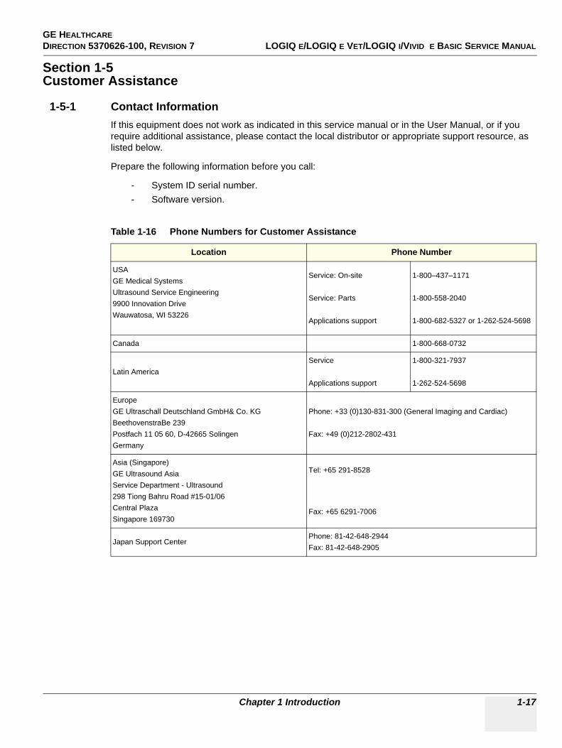
1-5-1 Contact InformationIf this equipment does not work as indicated in this service manual or in the User Manual, or if you require additional assistance, please contact the local distributor or appropriate support resource, as listed below.
Prepare the following information before you call:
- System ID serial number.- Software version.
Table 1-16 Phone Numbers for Customer Assistance
Location Phone Number
USAGE Medical SystemsUltrasound Service Engineering9900 Innovation DriveWauwatosa, WI 53226
Service: On-site
Service: Parts
Applications support
1-800–437–1171
1-800-558-2040
1-800-682-5327 or 1-262-524-5698
Canada 1-800-668-0732
Latin AmericaService
Applications support
1-800-321-7937
1-262-524-5698
EuropeGE Ultraschall Deutschland GmbH& Co. KGBeethovenstraBe 239Postfach 11 05 60, D-42665 SolingenGermany
Phone: +33 (0)130-831-300 (General Imaging and Cardiac)
Fax: +49 (0)212-2802-431
Asia (Singapore)GE Ultrasound AsiaService Department - Ultrasound298 Tiong Bahru Road #15-01/06Central PlazaSingapore 169730
Tel: +65 291-8528
Fax: +65 6291-7006
Japan Support CenterPhone: 81-42-648-2944Fax: 81-42-648-2905
GE HEALTHCAREDIRECTION 5370626-100, REVISION 7 LOGIQ E/LOGIQ E VET/LOGIQ I/VIVID E BASIC SERVICE MANUAL
1-18 Section 1-5 - Customer Assistance
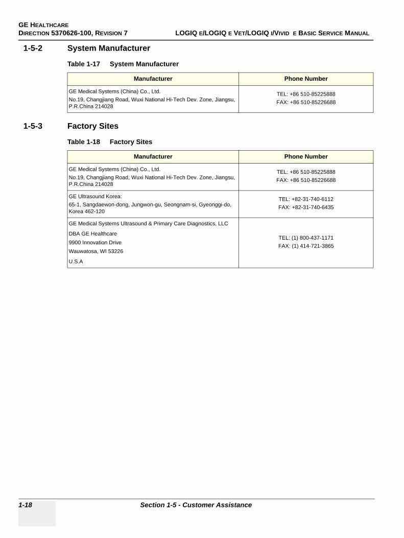
1-5-2 System Manufacturer
1-5-3 Factory Sites
Table 1-17 System Manufacturer
Manufacturer Phone Number
GE Medical Systems (China) Co., Ltd.No.19, Changjiang Road, Wuxi National Hi-Tech Dev. Zone, Jiangsu, P.R.China 214028
TEL: +86 510-85225888FAX: +86 510-85226688
Table 1-18 Factory Sites
Manufacturer Phone Number
GE Medical Systems (China) Co., Ltd.No.19, Changjiang Road, Wuxi National Hi-Tech Dev. Zone, Jiangsu, P.R.China 214028
TEL: +86 510-85225888FAX: +86 510-85226688
GE Ultrasound Korea:65-1, Sangdaewon-dong, Jungwon-gu, Seongnam-si, Gyeonggi-do, Korea 462-120
TEL: +82-31-740-6112FAX: +82-31-740-6435
GE Medical Systems Ultrasound & Primary Care Diagnostics, LLC
DBA GE Healthcare9900 Innovation DriveWauwatosa, WI 53226
U.S.A
TEL: (1) 800-437-1171FAX: (1) 414-721-3865
GE HEALTHCAREDIRECTION 5370626-100, REVISION 7 LOGIQ E/LOGIQ E VET/LOGIQ I/VIVID E BASIC SERVICE MANUAL
Chapter 2 Site preparations 2-1
Chapter 2Site preparations
Section 2-1Overview
2-1-1 Purpose of this chapter 2This chapter provides the information required to plan and prepare for the installation of a LOGIQ e/LOGIQ e Vet/LOGIQ i/Vivid e . Included are descriptions of the facility and electrical needs to be met by the purchaser of the unit.
2-1-2 Chapter Contents
Table 2-1 Contents in Chapter 2
Section Description Page Number
2-1 Overview 2-1
2-2 General Console Requirements 2-2
2-3 Facility Needs 2-6
GE HEALTHCAREDIRECTION 5370626-100, REVISION 7 LOGIQ E/LOGIQ E VET/LOGIQ I/VIVID E BASIC SERVICE MANUAL
2-2 Section 2-2 - General Console Requirements
Section 2-2General Console Requirements
2-2-1 Console Environmental Requirements
2-2-1-1 LightingBright light is needed for system installation, updates and repairs. However, operator and patient comfort may be optimized if the room light is subdued and indirect. Therefore a combination lighting system (dim/bright) is recommended. Keep in mind that lighting controls and diameters can be a source of EMI which could degrade image quality. These controls should be selected to minimize possible interface.
2-2-2 Electrical Requirements
NOTE: GE Medical Systems requires a dedicated power and ground for the proper operation of its Ultrasound equipment. This dedicated power shall originate at the last distribution panel before the system.
Sites with a mains power system with defined Neutral and Live:
The dedicated line shall consist of one phase, a neutral (not shared with any other circuit), and a full size ground wire from the distribution panel to the Ultrasound outlet.
Sites with a mains power system without a defined Neutral:
The dedicated line shall consist of one phase (two lines), not shared with any other circuit, and a full size ground wire from the distribution panel to the Ultrasound outlet.
Please note that image artifacts can occur, if at any time within the facility, the ground from the main facility's incoming power source to the Ultrasound unit is only a conduit.
2-2-2-1 LOGIQ e/LOGIQ e Vet/LOGIQ i/Vivid e Power Requirements
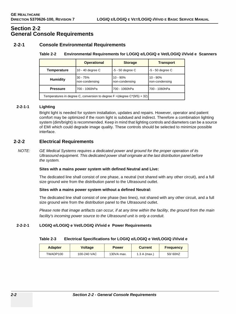
Table 2-2 Environmental Requirements for LOGIQ e/LOGIQ e Vet/LOGIQ i/Vivid e Scanners
Operational Storage Transport
Temperature 10 - 40 degree C -5 - 50 degree C -5 - 50 degree C
Humidity 30 - 75%non-condensing
10 - 90%non-condensing
10 - 90%non-condensing
Pressure 700 - 1060hPa 700 - 1060hPa 700 - 1060hPa
Temperatures in degree C, conversion to degree F =(degree C*(9/5) + 32)
Table 2-3 Electrical Specifications for LOGIQ e/LOGIQ e Vet/LOGIQ i/Vivid e
Adapter Voltage Power Current Frequency
TWADP100 100-240 VAC 130VA max. 1.3 A (max.) 50/ 60HZ
GE HEALTHCAREDIRECTION 5370626-100, REVISION 7 LOGIQ E/LOGIQ E VET/LOGIQ I/VIVID E BASIC SERVICE MANUAL
Chapter 2 Site preparations 2-3
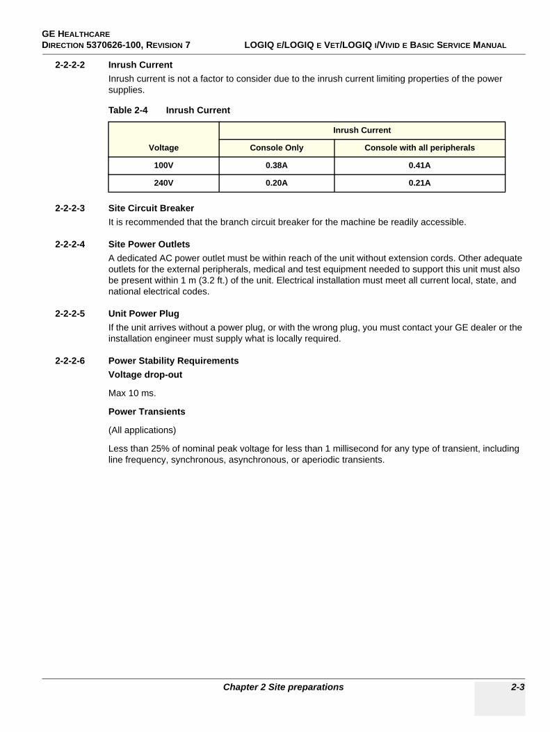
2-2-2-2 Inrush CurrentInrush current is not a factor to consider due to the inrush current limiting properties of the power supplies.
2-2-2-3 Site Circuit BreakerIt is recommended that the branch circuit breaker for the machine be readily accessible.
2-2-2-4 Site Power OutletsA dedicated AC power outlet must be within reach of the unit without extension cords. Other adequate outlets for the external peripherals, medical and test equipment needed to support this unit must also be present within 1 m (3.2 ft.) of the unit. Electrical installation must meet all current local, state, and national electrical codes.
2-2-2-5 Unit Power PlugIf the unit arrives without a power plug, or with the wrong plug, you must contact your GE dealer or the installation engineer must supply what is locally required.
2-2-2-6 Power Stability RequirementsVoltage drop-out
Max 10 ms.
Power Transients
(All applications)
Less than 25% of nominal peak voltage for less than 1 millisecond for any type of transient, including line frequency, synchronous, asynchronous, or aperiodic transients.
Table 2-4 Inrush Current
Voltage
Inrush Current
Console Only Console with all peripherals
100V 0.38A 0.41A
240V 0.20A 0.21A
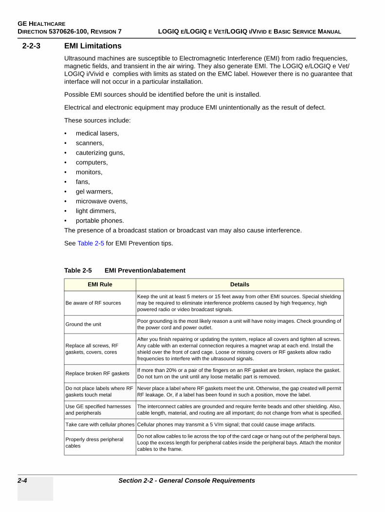
GE HEALTHCAREDIRECTION 5370626-100, REVISION 7 LOGIQ E/LOGIQ E VET/LOGIQ I/VIVID E BASIC SERVICE MANUAL
2-4 Section 2-2 - General Console Requirements
2-2-3 EMI LimitationsUltrasound machines are susceptible to Electromagnetic Interference (EMI) from radio frequencies, magnetic fields, and transient in the air wiring. They also generate EMI. The LOGIQ e/LOGIQ e Vet/LOGIQ i/Vivid e complies with limits as stated on the EMC label. However there is no guarantee that interface will not occur in a particular installation.
Possible EMI sources should be identified before the unit is installed.
Electrical and electronic equipment may produce EMI unintentionally as the result of defect.
These sources include:
• medical lasers,• scanners,• cauterizing guns,• computers,• monitors,• fans,• gel warmers,• microwave ovens,• light dimmers,• portable phones.The presence of a broadcast station or broadcast van may also cause interference.
See Table 2-5 for EMI Prevention tips.
Table 2-5 EMI Prevention/abatement
EMI Rule Details
Be aware of RF sourcesKeep the unit at least 5 meters or 15 feet away from other EMI sources. Special shielding may be required to eliminate interference problems caused by high frequency, high powered radio or video broadcast signals.
Ground the unit Poor grounding is the most likely reason a unit will have noisy images. Check grounding of the power cord and power outlet.
Replace all screws, RF gaskets, covers, cores
After you finish repairing or updating the system, replace all covers and tighten all screws. Any cable with an external connection requires a magnet wrap at each end. Install the shield over the front of card cage. Loose or missing covers or RF gaskets allow radio frequencies to interfere with the ultrasound signals.
Replace broken RF gaskets If more than 20% or a pair of the fingers on an RF gasket are broken, replace the gasket. Do not turn on the unit until any loose metallic part is removed.
Do not place labels where RF gaskets touch metal
Never place a label where RF gaskets meet the unit. Otherwise, the gap created will permit RF leakage. Or, if a label has been found in such a position, move the label.
Use GE specified harnesses and peripherals
The interconnect cables are grounded and require ferrite beads and other shielding. Also, cable length, material, and routing are all important; do not change from what is specified.
Take care with cellular phones Cellular phones may transmit a 5 V/m signal; that could cause image artifacts.
Properly dress peripheral cables
Do not allow cables to lie across the top of the card cage or hang out of the peripheral bays. Loop the excess length for peripheral cables inside the peripheral bays. Attach the monitor cables to the frame.

GE HEALTHCAREDIRECTION 5370626-100, REVISION 7 LOGIQ E/LOGIQ E VET/LOGIQ I/VIVID E BASIC SERVICE MANUAL
Chapter 2 Site preparations 2-5
2-2-4 Scan Probe Environmental RequirementsOperation:10° to 40° C
Storage:-10° to 50° C
NOTE: The recommended storage temperature range of 6Tc-RS is between 0°C and 45°C.
NOTE: Temperature in degrees C. Conversion to Degrees F = (Degrees C * (9/5) + 32).
NOTICE SYSTEMS AND ELECTRONIC PROBES ARE DESIGNED FOR STORAGE TEMPERATURES OF -10 TO + 60 degrees C. WHEN EXPOSED TO LARGE TEMPERATURE VARIATIONS, THE PRODUCT SHOULD BE KEPT IN ROOM TEMPERATURE FOR 10 HOURS BEFORE USE.
GE HEALTHCAREDIRECTION 5370626-100, REVISION 7 LOGIQ E/LOGIQ E VET/LOGIQ I/VIVID E BASIC SERVICE MANUAL
2-6 Section 2-3 - Facility Needs
Section 2-3Facility Needs
2-3-1 Recommended Ultrasound Room Layout
2-3-1-1 Purchaser ResponsibilitiesThe work and materials needed to prepare the site is the responsibility of the purchaser. Delay, confusion, and waste of manpower can be avoided by completing pre installation work before delivery. User the Pre Installation checklist to verify that all needed steps have been taken,Purchaser reasonability includes:
• Procuring the materials required.• Completing the preparations before delivery of the ultrasound system.• Paying the costs for any alternations and modifications not specifically provided in the sales
contract.
NOTE: All electrical installation that are preliminary to the positioning of the equipment at the site prepared for the equipment must be performed by licensed electrical contractors. Other connections between pieces of electrical equipment, products involved (and the accompanying electrical installations) are highly sophisticated and special engineering competence is required. All electrical work on these product must comply with the requirements of applicable electrical codes. The purchaser of GE equipment must only utilize qualified personnel to perform electrical servicing on the equipment.
The desire to use a non-listed or customer provided product or to place an approved product further from the system than the interface kit allows presents challenges to the installation team. To avoid delays during installation, such variances should be made known to the individuals or group performing the installation at the earliest possible date (preferable prior to purchase).The ultrasound suite must be clean prior to delivery of the machine. Carpet is not recommended because it collects dust and creates static. Potential sources of EMI (electromagnetic interference) should also be investigated before delivery. Dirt, static, and EMI can negatively impact system.

GE HEALTHCAREDIRECTION 5370626-100, REVISION 7 LOGIQ E/LOGIQ E VET/LOGIQ I/VIVID E BASIC SERVICE MANUAL
Chapter 2 Site preparations 2-7
2-3-2 Required Features
NOTE: GE Medical Systems requires a dedicated power and ground for the proper operation of its Ultrasound equipment. This dedicated power shall originate at the last distribution panel before the system.
Sites with a mains power system with defined Neutral and Live:
The dedicated line shall consist of one phase, a neutral (not shared with any other circuit), and a full size ground wire from the distribution panel to the Ultrasound outlet.
Sites with a mains power system without a defined Neutral:
The dedicated line shall consist of one phase (two lines), not shared with any other circuit, and a full size ground wire from the distribution panel to the Ultrasound outlet.
Please note that image artifacts can occur, if at any time within the facility, the ground from the main facility's incoming power source to the Ultrasound unit is only a conduit.
• Dedicated single branch power outlet of adequate amperage meeting all local and national codes which is located less than 2.5 m (8 ft.) from the unit’s proposed location
• Door opening is at least 76 cm (30 in) wide• Proposed location for unit is at least 0.2m (0.67 ft.) from the wall for cooling• Power outlet and place for any external peripheral are within 2 m (6.5 ft.) of each other with
peripheral within 1 m of the unit to connect cables.• Power outlets for other medical equipment and gel warmer• Power outlets for test equipment and modem within 1 m (3.2 ft.) of unit• Clean and protected space to store transducers (in their cases or on a rack)• Material to safely clean probes (done with a plastic container, never metal)
2-3-3 Desirable Features• Door is at least 92 cm (3 ft.) wide• Circuit breaker for dedicated power outlet is easily accessible• Sink with hot and cold water• Receptacle for bio–hazardous waste, like used probe sheaths• Emergency oxygen supply• Storage for linens and equipment• Nearby waiting room, lavatory, and dressing room• Dual level lighting (bright and dim)• Lockable cabinet ordered by GE for its software and proprietary manuals.
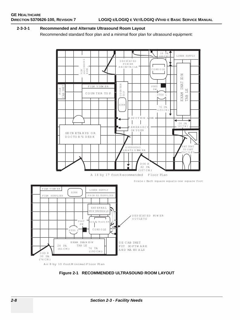
GE HEALTHCAREDIRECTION 5370626-100, REVISION 7 LOGIQ E/LOGIQ E VET/LOGIQ I/VIVID E BASIC SERVICE MANUAL
2-8 Section 2-3 - Facility Needs
2-3-3-1 Recommended and Alternate Ultrasound Room LayoutRecommended standard floor plan and a minimal floor plan for ultrasound equipment:
Figure 2-1 RECOMMENDED ULTRASOUND ROOM LAYOUT
LINEN SUPPLY
EXAM
INATIO
NTABLE
FILM VIEW ER
C O UN TER TO P
FILE
CABINET
SE CR ETA R YS O RD O C TO R ’S D ES K
FILM
PROCESSING
ROOM
,
O VER H EA DLIG H TS D IMM ER
D ED IC AT EDPO W ER
R EC EP TA C LE
EXT ER N A LPE R IPH ER A LS
SINK
COUNTER
TOP
FILM VIEW ER
FILM SUPPLIES
SINKLINEN SUPPLY
PR OB ES /SUPPLIES
24 IN.(61 C M )
EXAM INA R IO NTAB LE
76 IN.(193 C M )
D OO R30 IN.(76 C M )
A n 8 by 10 foot M inimal Floor Plan
D ED IC AT ED PO W ERO U TLETS
A 14 by 17 foot R ecommended Floor Plan
G E C AB INETFOT SO FTW A R EA N D MA NU A LS
Scale : Each square equals one square foot
D OO R42 IN.
(107 C M )
SU C TIO N LINE
EM ER G EC YOX YG EN
24 IN.(61 C M )
76 IN.(193 C M )
PAT IENTTO ILETFA C ILITY
FOOTSW
FOOTSW
LO G IQ B ook XP
C O NS O LE
C O NS O LE
18 IN.(46 C M )
STOO L
STOO L
GE HEALTHCAREDIRECTION 5370626-100, REVISION 7 LOGIQ E/LOGIQ E VET/LOGIQ I/VIVID E BASIC SERVICE MANUAL
Chapter 2 Site preparations 2-9
2-3-4 Networking Pre-installation Requirements
2-3-4-1 Stand Alone Scanner (without Network Connection)None.
2-3-4-2 Scanner Connected to Hospital’s NetworkSupported networks:
Wireless LAN
2-3-4-3 Purpose of DICOM Network FunctionDICOM services provide the operator with clinically useful features for moving images and patient information over a hospital network. Examples of DICOM services include the transfer of images to workstations for viewing or transferring images to remote printers. As an added benefit, transferring images in this manner frees up the on-board monitor and peripherals, enabling viewing to be done while scanning continues. With DICOM, images can be archived, stored, and retrieved faster, easier, and at a lower cost.
2-3-4-4 DICOM Option Pre-installation RequirementsTo configure the LOGIQ e/LOGIQ e Vet/LOGIQ i/Vivid e to work with other network connections, the site’s network administrator must provide some necessary information.
Information must include:
• A host name, local port number, AE Title, IP address and Net Mask for the LOGIQ e/LOGIQ e Vet/LOGIQ i/Vivid e .
• The IP addresses for the default gateway and other routers at the site for ROUTING INFORMATION.
• The host name, IP address, port and AE Title for each device the site wants connected to the LOGIQ e/LOGIQ e Vet/LOGIQ i/Vivid e for DICOM APPLICATION INFORMATION. A field for the make (manufacturer) and the revision of the device, is also included. This information may be useful for solving errors.
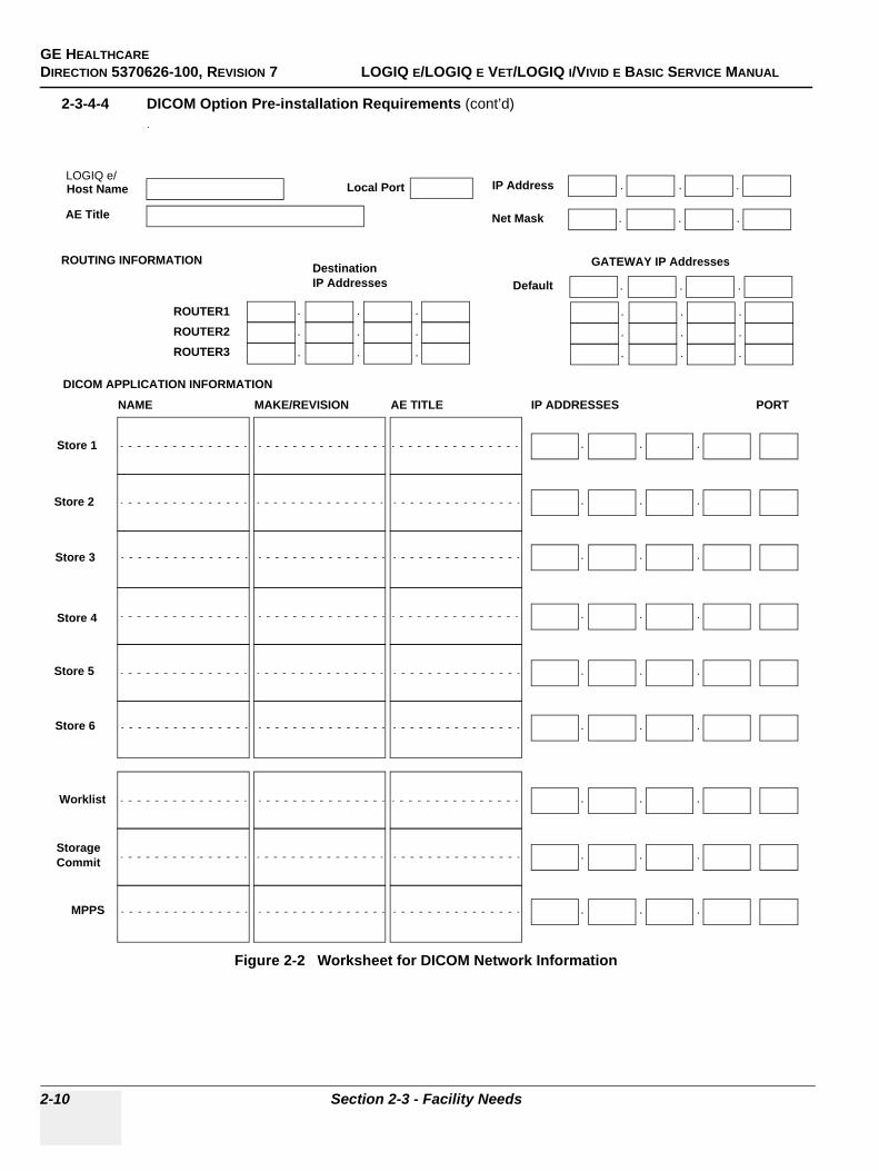
GE HEALTHCAREDIRECTION 5370626-100, REVISION 7 LOGIQ E/LOGIQ E VET/LOGIQ I/VIVID E BASIC SERVICE MANUAL
2-10 Section 2-3 - Facility Needs
2-3-4-4 DICOM Option Pre-installation Requirements (cont’d).
Figure 2-2 Worksheet for DICOM Network Information
LOGIQ e/Host Name
AE Title
Local Port IP Address
Net Mask
.. .
.. .
ROUTING INFORMATION
ROUTER2ROUTER3
ROUTER1
.. .
.. .
.. .
.. .
.. .
.. .
.. .
Destination IP Addresses
GATEWAY IP Addresses
Default
DICOM APPLICATION INFORMATION
NAME
Store 2
Store 3
Store 1
MAKE/REVISION IP ADDRESSES PORTAE TITLE
Store 5
Store 6
Store 4
Storage Commit
MPPS
Worklist .. .
.. .
.. .
.. .
.. .
.. .
.. .
.. .
.. .
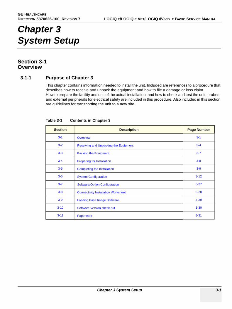
GE HEALTHCAREDIRECTION 5370626-100, REVISION 7 LOGIQ E/LOGIQ E VET/LOGIQ I/VIVID E BASIC SERVICE MANUAL
Chapter 3 System Setup 3-1
Chapter 3System Setup
Section 3-1Overview
3-1-1 Purpose of Chapter 3This chapter contains information needed to install the unit. Included are references to a procedure that describes how to receive and unpack the equipment and how to file a damage or loss claim.How to prepare the facility and unit of the actual installation, and how to check and test the unit, probes, and external peripherals for electrical safety are included in this procedure. Also included in this section are guidelines for transporting the unit to a new site.
Table 3-1 Contents in Chapter 3
Section Description Page Number
3-1 Overview 3-1
3-2 Receiving and Unpacking the Equipment 3-4
3-3 Packing the Equipment 3-7
3-4 Preparing for Installation 3-8
3-5 Completing the Installation 3-9
3-6 System Configuration 3-12
3-7 Software/Option Configuration 3-27
3-8 Connectivity Installation Worksheet 3-28
3-9 Loading Base Image Software 3-29
3-10 Software Version check out 3-30
3-11 Paperwork 3-31

GE HEALTHCAREDIRECTION 5370626-100, REVISION 7 LOGIQ E/LOGIQ E VET/LOGIQ I/VIVID E BASIC SERVICE MANUAL
3-2 Section 3-1 - Overview
3-1-2 Average Installation Time
The LOGIQ e/LOGIQ e Vet/LOGIQ i/Vivid e installation and functional checkout will take approximately one hour. LOGIQ e/LOGIQ e Vet/LOGIQ i/Vivid e consoles with optional equipment may take slightly longer.
Table 3-2 Average Installation Time
Description Average Installation Time Comments
Unpacking the scanner 20 minutes
Scanner wo/options 30 minutes Dependent on the configuration that is required
DICOM Option 30 minutes Dependent on the amount of configuration
GE HEALTHCAREDIRECTION 5370626-100, REVISION 7 LOGIQ E/LOGIQ E VET/LOGIQ I/VIVID E BASIC SERVICE MANUAL
Chapter 3 System Setup 3-3
3-1-3 Installation Warnings8.) There are no operator serviceable components. To prevent shock, do not remove any covers or
panels. Should problems or malfunctions occur, unplug the power cord. Only qualified service personnel should carry out servicing.
NOTE: For information regarding packing labels, refer to LABELS ON PACKAGE.
9.) After being transported, the unit may be very cold or hot. If this is the case, allow the unit to acclimate before you turn it on. It requires one hour for each 2.5×C increment it's temperature is below 10×C or above 40×C.
3-1-4 Safety Reminders
DANGER Equipment damage possibility. Turning the system on without acclimation after arriving at site may cause the system to be damaged.
Table 3-3 Time for Settlement
°C 60 55 50 45 40 35 30 25 20 15 10 5 0 -5 -10 -15 -20 -25 -30 -35 -40
°F 140 131 122 113 104 95 86 77 68 59 50 41 32 23 14 5 -4 -13 -22 -31 -40
hrs 8 6 4 2 0 0 0 0 0 0 0 2 4 6 8 10 12 14 16 18 20
DANGER WHEN USING ANY TEST INSTRUMENT THAT IS CAPABLE OF OPENING THE AC GROUND LINE (I.E., METER’S GROUND SWITCH IS OPEN), DON’T TOUCH THE UNIT!
CAUTION If the unit is very cold or hot, do not turn on its power until it has had a chance to acclimate to its operating environment.
DANGER To prevent electrical shock, connect the unit to a properly grounded power outlet. Do not use a three to two prong adapter. This defeats safety grounding.
DANGER Do not operate this unit unless all board covers are securely in place.
DANGER OPERATOR MANUAL(S) The User Manual(s) should be fully read and understood before operating the LOGIQ e/LOGIQ e Vet/LOGIQ i/Vivid e and kept near the unit for quick reference.
DANGER ACOUSTIC OUTPUT HAZARDAlthough the ultrasound energy transmitted from the LOGIQ e/LOGIQ e Vet/LOGIQ i/Vivid e probe is within FDA limits, avoid unnecessary exposure. Ultrasound energy can produce heat and mechanical damage
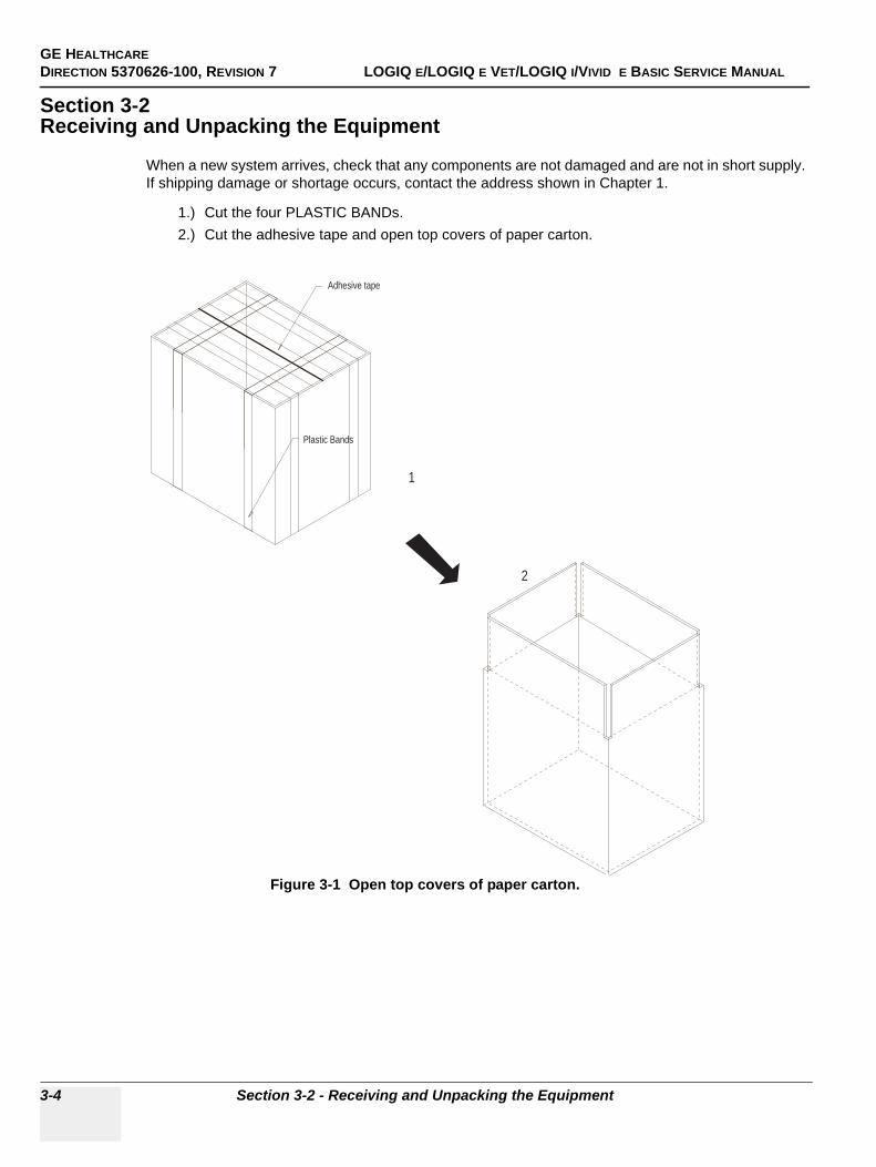
GE HEALTHCAREDIRECTION 5370626-100, REVISION 7 LOGIQ E/LOGIQ E VET/LOGIQ I/VIVID E BASIC SERVICE MANUAL
3-4 Section 3-2 - Receiving and Unpacking the Equipment
Section 3-2Receiving and Unpacking the Equipment
When a new system arrives, check that any components are not damaged and are not in short supply. If shipping damage or shortage occurs, contact the address shown in Chapter 1.
1.) Cut the four PLASTIC BANDs.2.) Cut the adhesive tape and open top covers of paper carton.
Figure 3-1 Open top covers of paper carton.
Adhesive tape
Plastic Bands
1
2
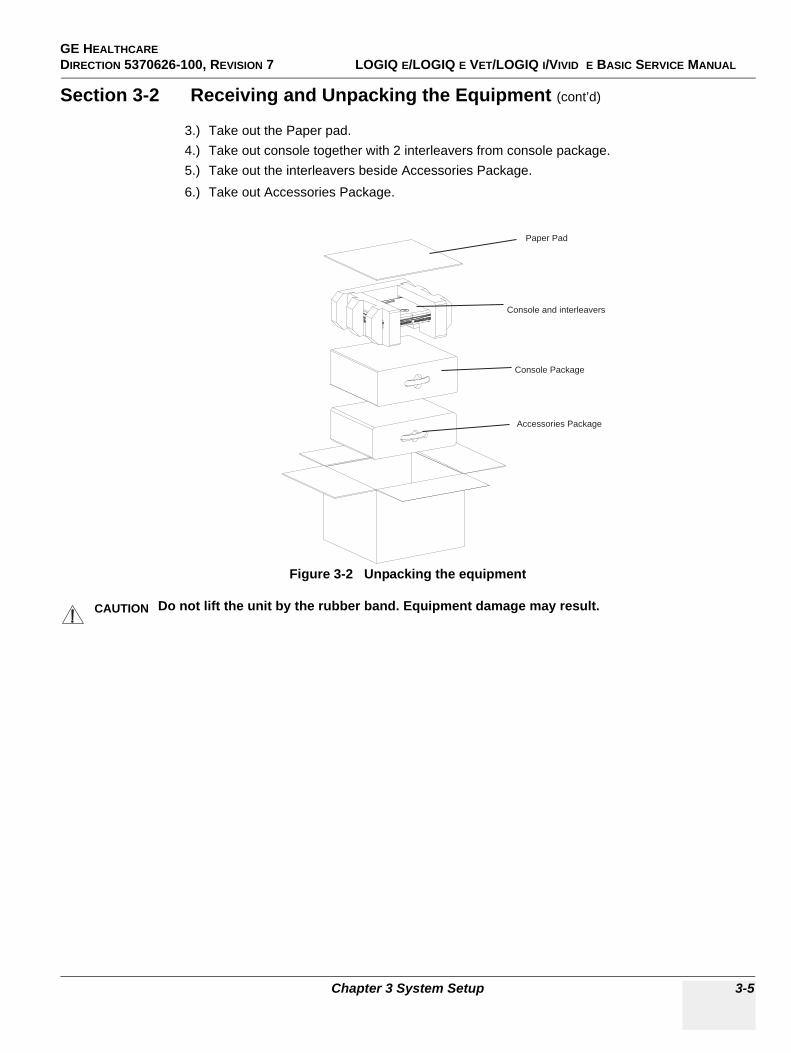
GE HEALTHCAREDIRECTION 5370626-100, REVISION 7 LOGIQ E/LOGIQ E VET/LOGIQ I/VIVID E BASIC SERVICE MANUAL
Chapter 3 System Setup 3-5
Section 3-2 Receiving and Unpacking the Equipment (cont’d)
3.) Take out the Paper pad.4.) Take out console together with 2 interleavers from console package.5.) Take out the interleavers beside Accessories Package.6.) Take out Accessories Package.
Figure 3-2 Unpacking the equipment
CAUTION Do not lift the unit by the rubber band. Equipment damage may result.
Paper Pad
Console and interleavers
Console Package
Accessories Package
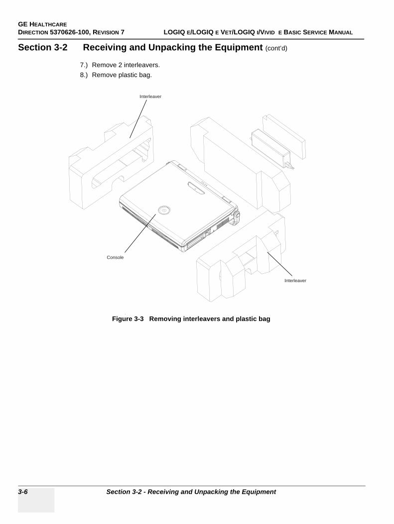
GE HEALTHCAREDIRECTION 5370626-100, REVISION 7 LOGIQ E/LOGIQ E VET/LOGIQ I/VIVID E BASIC SERVICE MANUAL
3-6 Section 3-2 - Receiving and Unpacking the Equipment
Section 3-2 Receiving and Unpacking the Equipment (cont’d)
7.) Remove 2 interleavers.8.) Remove plastic bag.
Figure 3-3 Removing interleavers and plastic bag
Console
Interleaver
Interleaver
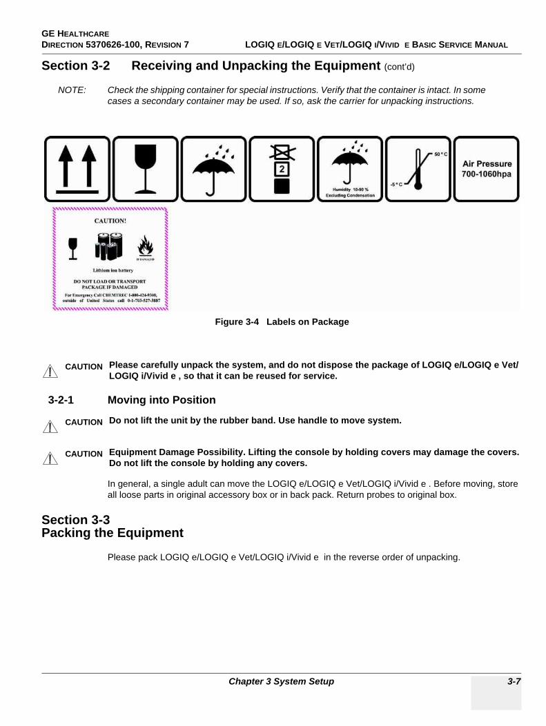
GE HEALTHCAREDIRECTION 5370626-100, REVISION 7 LOGIQ E/LOGIQ E VET/LOGIQ I/VIVID E BASIC SERVICE MANUAL
Chapter 3 System Setup 3-7
Section 3-2 Receiving and Unpacking the Equipment (cont’d)
NOTE: Check the shipping container for special instructions. Verify that the container is intact. In some cases a secondary container may be used. If so, ask the carrier for unpacking instructions.
3-2-1 Moving into Position
In general, a single adult can move the LOGIQ e/LOGIQ e Vet/LOGIQ i/Vivid e . Before moving, store all loose parts in original accessory box or in back pack. Return probes to original box.
Section 3-3Packing the Equipment
Please pack LOGIQ e/LOGIQ e Vet/LOGIQ i/Vivid e in the reverse order of unpacking.
Figure 3-4 Labels on Package
CAUTION Please carefully unpack the system, and do not dispose the package of LOGIQ e/LOGIQ e Vet/LOGIQ i/Vivid e , so that it can be reused for service.
CAUTION Do not lift the unit by the rubber band. Use handle to move system.
CAUTION Equipment Damage Possibility. Lifting the console by holding covers may damage the covers. Do not lift the console by holding any covers.

GE HEALTHCAREDIRECTION 5370626-100, REVISION 7 LOGIQ E/LOGIQ E VET/LOGIQ I/VIVID E BASIC SERVICE MANUAL
3-8 Section 3-4 - Preparing for Installation
Section 3-4Preparing for Installation
3-4-1 Verify Customer OrderCompare items received by the customer to that which is listed on the delivery order. Report any items that are missing, back ordered or damaged.
3-4-2 Physical Inspection
3-4-2-1 System Voltage Settings• Verify that the scanner is set to the correct voltage. The Voltage settings for the LOGIQ e/LOGIQ e
Vet/LOGIQ i/Vivid e Scanner is found on a label located on the AC adapter.• 220-240VAC(China); 100-120VAC(USA/Japan); 220-240VAC(Europe, Latin America).
3-4-3 EMI ProtectionThis Unit has been designed to minimize the effects of Electro Magnetic Interference (EMI). Many of the covers, shields, and screws are provided primarily to protect the system from image artifacts caused by this interference. For this reason, it is imperative that all covers and hardware are installed and secured before the unit is put into operation.
WARNINGWARNING Connecting a LOGIQ e/LOGIQ e Vet/LOGIQ i/Vivid e scanner to the wrong voltage level will most likely destroy the scanner.
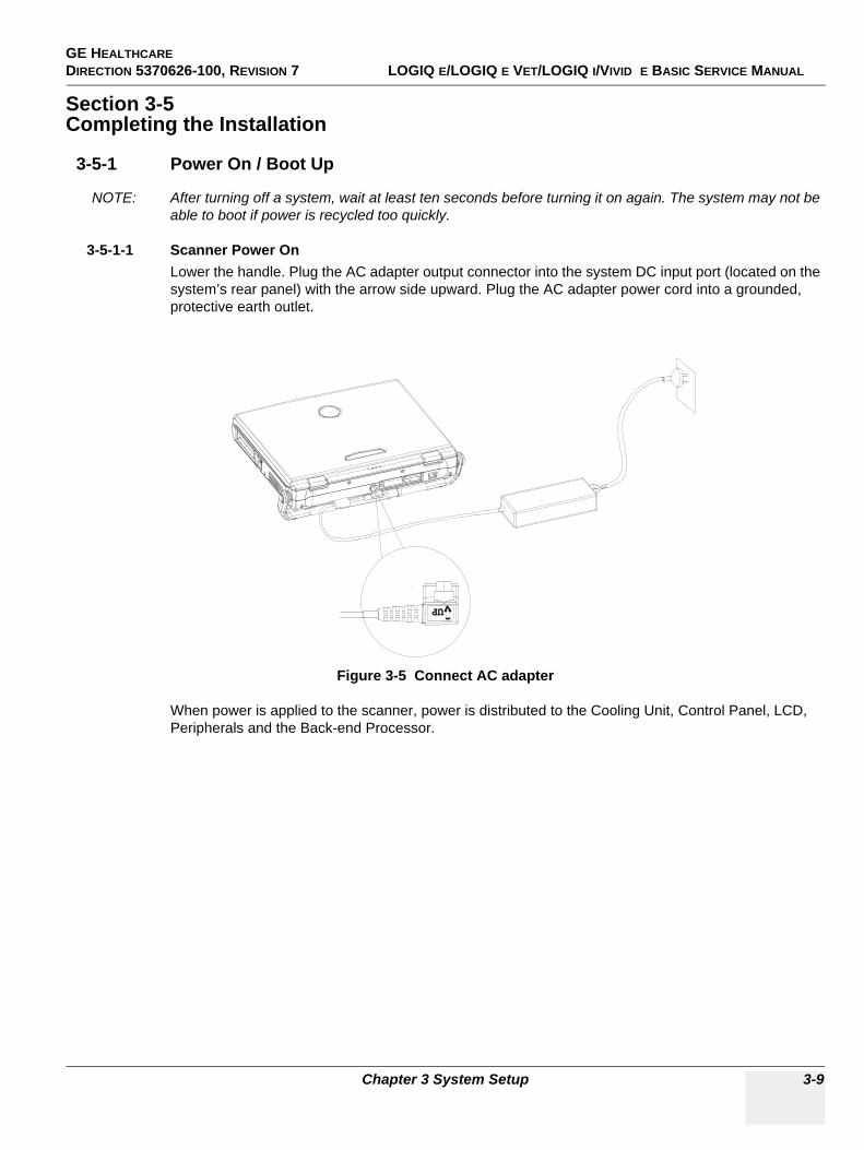
GE HEALTHCAREDIRECTION 5370626-100, REVISION 7 LOGIQ E/LOGIQ E VET/LOGIQ I/VIVID E BASIC SERVICE MANUAL
Chapter 3 System Setup 3-9
Section 3-5Completing the Installation
3-5-1 Power On / Boot Up
NOTE: After turning off a system, wait at least ten seconds before turning it on again. The system may not be able to boot if power is recycled too quickly.
3-5-1-1 Scanner Power OnLower the handle. Plug the AC adapter output connector into the system DC input port (located on the system’s rear panel) with the arrow side upward. Plug the AC adapter power cord into a grounded, protective earth outlet.
When power is applied to the scanner, power is distributed to the Cooling Unit, Control Panel, LCD, Peripherals and the Back-end Processor.
Figure 3-5 Connect AC adapter
UPUP

GE HEALTHCAREDIRECTION 5370626-100, REVISION 7 LOGIQ E/LOGIQ E VET/LOGIQ I/VIVID E BASIC SERVICE MANUAL
3-10 Section 3-5 - Completing the Installation
3-5-1-2 Turn on the systemPress the Power On/Off switch at the front of the system once.
When the Power On/Off switch on the Control Panel is pressed once, the Back-end Processor starts and the software code is distributed to initiate the scanner.
No status messages are displayed during this process.
3-5-2 Power Off/ Shutdown
NOTE: After turning off a system, wait at least ten seconds before turning it on again. The system may not be able to boot if power is recycled too quickly.
3-5-2-1 Back-end Processor Power DownTo power down the system:
1.) Press the Power On/Off switch at the front of the system once.2.) The System-Exit window is displayed.
3.) Using the Trackball or Select key, select Shutdown.4.) The shutdown process takes a few seconds and is complete when the power status LED is turned
off.5.) Disconnect the probes.Clean or disinfect all probes as necessary. Store them in their shipping
cases to avoid damage.6.) Close LCD cover.
Figure 3-6 Power On/Off Switch
Figure 3-7 System Exit Window
Power On/Off switch
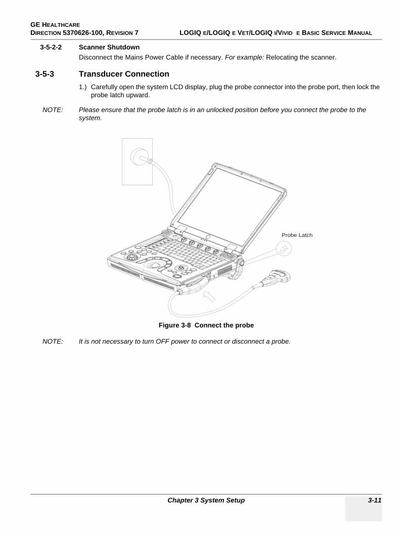
GE HEALTHCAREDIRECTION 5370626-100, REVISION 7 LOGIQ E/LOGIQ E VET/LOGIQ I/VIVID E BASIC SERVICE MANUAL
Chapter 3 System Setup 3-11
3-5-2-2 Scanner ShutdownDisconnect the Mains Power Cable if necessary. For example: Relocating the scanner.
3-5-3 Transducer Connection1.) Carefully open the system LCD display, plug the probe connector into the probe port, then lock the
probe latch upward.
NOTE: Please ensure that the probe latch is in an unlocked position before you connect the probe to the system.
NOTE: It is not necessary to turn OFF power to connect or disconnect a probe.
Figure 3-8 Connect the probe
Probe Latch
GE HEALTHCAREDIRECTION 5370626-100, REVISION 7 LOGIQ E/LOGIQ E VET/LOGIQ I/VIVID E BASIC SERVICE MANUAL
3-12 Section 3-6 - System Configuration
Section 3-6System Configuration
3-6-1 System Specifications
3-6-1-1 Physical DimensionsThe physical dimensions of the LOGIQ e/LOGIQ e Vet/LOGIQ i/Vivid e console are summarized in Figure 3-9 on page 3-12 .
3-6-2 Electrical Specifications
Table 3-4 Physical Dimensions of LOGIQ e/LOGIQ e Vet/LOGIQ i/Vivid e
Height Width Depth Unit
Console Only
Console with handle
Console Only
Console with handle Console Only
Console with handle Unit
61 100 340 375 287 337 mm
2.4 3.9 13.4 14.8 11.3 13.3 inches
Figure 3-9 Overall Dimensions
Table 3-5 Electrical Specifications for LOGIQ e/LOGIQ e Vet/LOGIQ i/Vivid e
Adapter Voltage Tolerances Current Frequency
TWADP100 100-240 VAC +/-10% 1.3A (max) 50/60Hz
WEIGHT: 4.6KG NOTE: Length is in mm
GE HEALTHCAREDIRECTION 5370626-100, REVISION 7 LOGIQ E/LOGIQ E VET/LOGIQ I/VIVID E BASIC SERVICE MANUAL
Chapter 3 System Setup 3-13
3-6-3 Approved peripherals
NOTE: For detailed installation information and connection procedures, please refer to Peripheral Installation manual.
NOTE: BarCode Reader* is supported by LOGIQ e Software version R5.2.x, R6.x.x only.
Table 3-6 Approved on-board peripherals
Device Manufacturer Model Interface Remark
B/W Printer SONY UP-D897 USB
Digital Color PrinterSONY UP-D23MD USB
SONY UP-D25MD USB
HP Color Printer
HP HP Officejet Pro K5400 USB
HP HP Officejet Pro K8600 USB
HP HP Deskjet 470 USB
DVD-RW
LITEON LITEON DX-20A4P USB
LITEON LITEON Model eHAU 120 USB
LITEON LITEON Model eHAU 324 USB
Wireless Lan Adapter
NetGear WN111V2 USB
NetGear WG111V3 USB
Linksys Linksys WUSB54G USB
3-pedal footswitch Steute MKF 2-MED GP26 USB
1-pedal footswitch Whanam FSU2001 USB
1-pedal footswitch Whanam FSU-1000 USB
USB Memory
SanDisk CRUZER 2G USB
SanDisk CRUZER 4G USB
SanDisk CRUZER 4G with U3 Application USB Only supported by LOGIQ e R6.x.x
and LOGIQ e R7.x.x.
USB HUBShenzhen Gaojian HE 702A USB
Shenzhen Gaojian HE420GE USB
ECG NORAV ECG-USB1 USB
USB HDD
Seagate USB HDD 80G USB
Seagate USB HDD 250G USB
Seagate USB HDD 500G USB
DVD-Recorder PanasonicMD-800EMD-800U USB
Not supported by LOGIQ e R4.x.x, LOGIQ e R6.x.x, Vivid e R4.x.x,
LOGIQ i R4.x.x
Video Transfer PinnaclePinnacle Video Transfer -
8230-10022-11 USBNot supported by LOGIQ e R5.0.x,
LOGIQ e Vet R5.0.x, Vivid e R5.0.x, LOGIQ i R5.0.x
BarCode Reader*Handheld Handheld 3800G USB Only supported by LOGIQ e R5.2.x,
R6.x.x, R7.x.x, LOGIQ e Vet 6.x.xHandheld Handheld 4600G USB
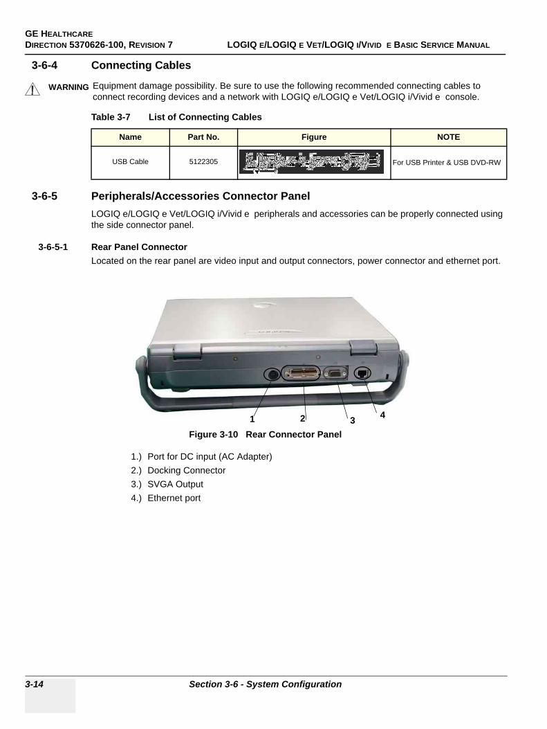
GE HEALTHCAREDIRECTION 5370626-100, REVISION 7 LOGIQ E/LOGIQ E VET/LOGIQ I/VIVID E BASIC SERVICE MANUAL
3-14 Section 3-6 - System Configuration
3-6-4 Connecting Cables
3-6-5 Peripherals/Accessories Connector PanelLOGIQ e/LOGIQ e Vet/LOGIQ i/Vivid e peripherals and accessories can be properly connected using the side connector panel.
3-6-5-1 Rear Panel ConnectorLocated on the rear panel are video input and output connectors, power connector and ethernet port.
1.) Port for DC input (AC Adapter)2.) Docking Connector3.) SVGA Output4.) Ethernet port
WARNINGWARNING Equipment damage possibility. Be sure to use the following recommended connecting cables to connect recording devices and a network with LOGIQ e/LOGIQ e Vet/LOGIQ i/Vivid e console.
Table 3-7 List of Connecting Cables
Name Part No. Figure NOTE
USB Cable 5122305 For USB Printer & USB DVD-RW
Figure 3-10 Rear Connector Panel
43
21
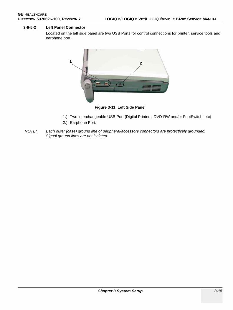
GE HEALTHCAREDIRECTION 5370626-100, REVISION 7 LOGIQ E/LOGIQ E VET/LOGIQ I/VIVID E BASIC SERVICE MANUAL
Chapter 3 System Setup 3-15
3-6-5-2 Left Panel ConnectorLocated on the left side panel are two USB Ports for control connections for printer, service tools and earphone port.
1.) Two interchangeable USB Port (Digital Printers, DVD-RW and/or FootSwitch, etc)2.) Earphone Port.
NOTE: Each outer (case) ground line of peripheral/accessory connectors are protectively grounded. Signal ground lines are not isolated.
Figure 3-11 Left Side Panel
21
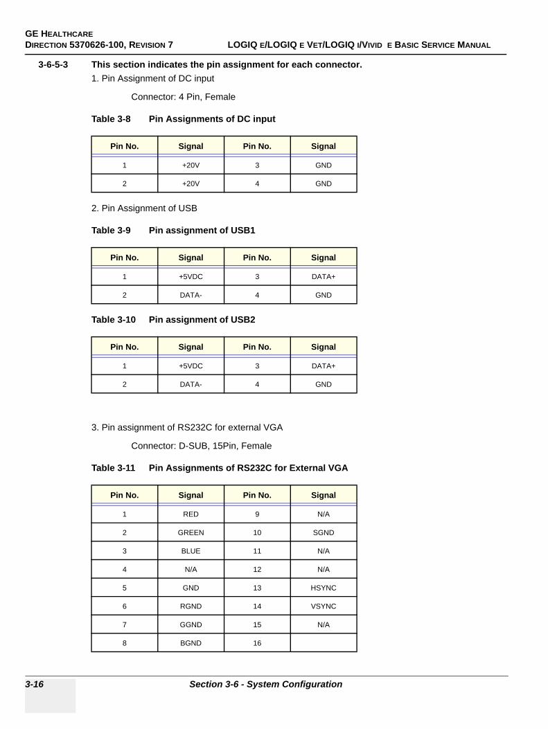
GE HEALTHCAREDIRECTION 5370626-100, REVISION 7 LOGIQ E/LOGIQ E VET/LOGIQ I/VIVID E BASIC SERVICE MANUAL
3-16 Section 3-6 - System Configuration
3-6-5-3 This section indicates the pin assignment for each connector.1. Pin Assignment of DC input
Connector: 4 Pin, Female
Table 3-8 Pin Assignments of DC input
2. Pin Assignment of USB
Table 3-9 Pin assignment of USB1
Table 3-10 Pin assignment of USB2
3. Pin assignment of RS232C for external VGA
Connector: D-SUB, 15Pin, Female
Table 3-11 Pin Assignments of RS232C for External VGA
Pin No. Signal Pin No. Signal
1 +20V 3 GND
2 +20V 4 GND
Pin No. Signal Pin No. Signal
1 +5VDC 3 DATA+
2 DATA- 4 GND
Pin No. Signal Pin No. Signal
1 +5VDC 3 DATA+
2 DATA- 4 GND
Pin No. Signal Pin No. Signal
1 RED 9 N/A
2 GREEN 10 SGND
3 BLUE 11 N/A
4 N/A 12 N/A
5 GND 13 HSYNC
6 RGND 14 VSYNC
7 GGND 15 N/A
8 BGND 16
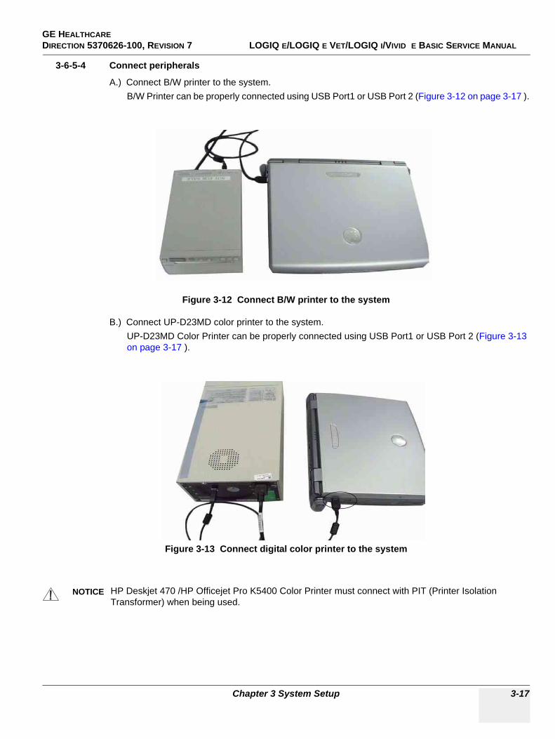
GE HEALTHCAREDIRECTION 5370626-100, REVISION 7 LOGIQ E/LOGIQ E VET/LOGIQ I/VIVID E BASIC SERVICE MANUAL
Chapter 3 System Setup 3-17
3-6-5-4 Connect peripherals
A.) Connect B/W printer to the system.B/W Printer can be properly connected using USB Port1 or USB Port 2 (Figure 3-12 on page 3-17 ).
B.) Connect UP-D23MD color printer to the system.UP-D23MD Color Printer can be properly connected using USB Port1 or USB Port 2 (Figure 3-13 on page 3-17 ).
Figure 3-12 Connect B/W printer to the system
Figure 3-13 Connect digital color printer to the system
NOTICE HP Deskjet 470 /HP Officejet Pro K5400 Color Printer must connect with PIT (Printer Isolation Transformer) when being used.
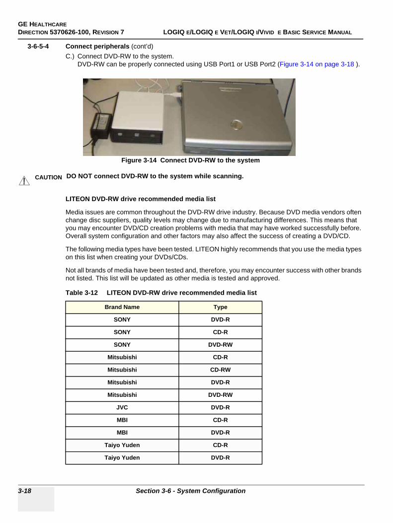
GE HEALTHCAREDIRECTION 5370626-100, REVISION 7 LOGIQ E/LOGIQ E VET/LOGIQ I/VIVID E BASIC SERVICE MANUAL
3-18 Section 3-6 - System Configuration
3-6-5-4 Connect peripherals (cont’d)C.) Connect DVD-RW to the system.
DVD-RW can be properly connected using USB Port1 or USB Port2 (Figure 3-14 on page 3-18 ).
LITEON DVD-RW drive recommended media list
Media issues are common throughout the DVD-RW drive industry. Because DVD media vendors often change disc suppliers, quality levels may change due to manufacturing differences. This means that you may encounter DVD/CD creation problems with media that may have worked successfully before. Overall system configuration and other factors may also affect the success of creating a DVD/CD.
The following media types have been tested. LITEON highly recommends that you use the media types on this list when creating your DVDs/CDs.
Not all brands of media have been tested and, therefore, you may encounter success with other brands not listed. This list will be updated as other media is tested and approved.
Figure 3-14 Connect DVD-RW to the system
CAUTION DO NOT connect DVD-RW to the system while scanning.
Table 3-12 LITEON DVD-RW drive recommended media list
Brand Name Type
SONY DVD-R
SONY CD-R
SONY DVD-RW
Mitsubishi CD-R
Mitsubishi CD-RW
Mitsubishi DVD-R
Mitsubishi DVD-RW
JVC DVD-R
MBI CD-R
MBI DVD-R
Taiyo Yuden CD-R
Taiyo Yuden DVD-R
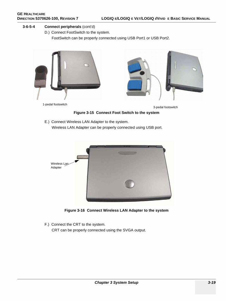
GE HEALTHCAREDIRECTION 5370626-100, REVISION 7 LOGIQ E/LOGIQ E VET/LOGIQ I/VIVID E BASIC SERVICE MANUAL
Chapter 3 System Setup 3-19
3-6-5-4 Connect peripherals (cont’d)D.) Connect FootSwitch to the system.
FootSwitch can be properly connected using USB Port1 or USB Port2.
E.) Connect Wireless LAN Adapter to the system.Wireless LAN Adapter can be properly connected using USB port.
F.) Connect the CRT to the system.CRT can be properly connected using the SVGA output.
Figure 3-15 Connect Foot Switch to the system
Figure 3-16 Connect Wireless LAN Adapter to the system
3-pedal footswitch1-pedal footswitch
Wireless Lan Adapter
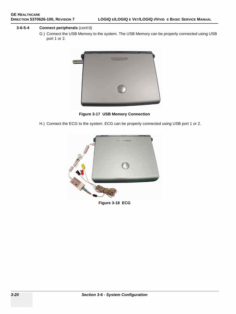
GE HEALTHCAREDIRECTION 5370626-100, REVISION 7 LOGIQ E/LOGIQ E VET/LOGIQ I/VIVID E BASIC SERVICE MANUAL
3-20 Section 3-6 - System Configuration
3-6-5-4 Connect peripherals (cont’d)G.) Connect the USB Memory to the system. The USB Memory can be properly connected using USB
port 1 or 2.
H.) Connect the ECG to the system. ECG can be properly connected using USB port 1 or 2.
Figure 3-17 USB Memory Connection
Figure 3-18 ECG
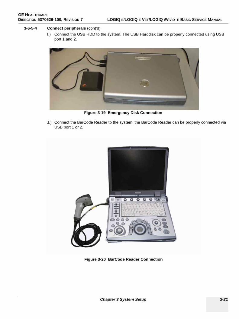
GE HEALTHCAREDIRECTION 5370626-100, REVISION 7 LOGIQ E/LOGIQ E VET/LOGIQ I/VIVID E BASIC SERVICE MANUAL
Chapter 3 System Setup 3-21
3-6-5-4 Connect peripherals (cont’d)I.) Connect the USB HDD to the system. The USB Harddisk can be properly connected using USB
port 1 and 2.
J.) Connect the BarCode Reader to the system, the BarCode Reader can be properly connected via USB port 1 or 2.
Figure 3-19 Emergency Disk Connection
Figure 3-20 BarCode Reader Connection
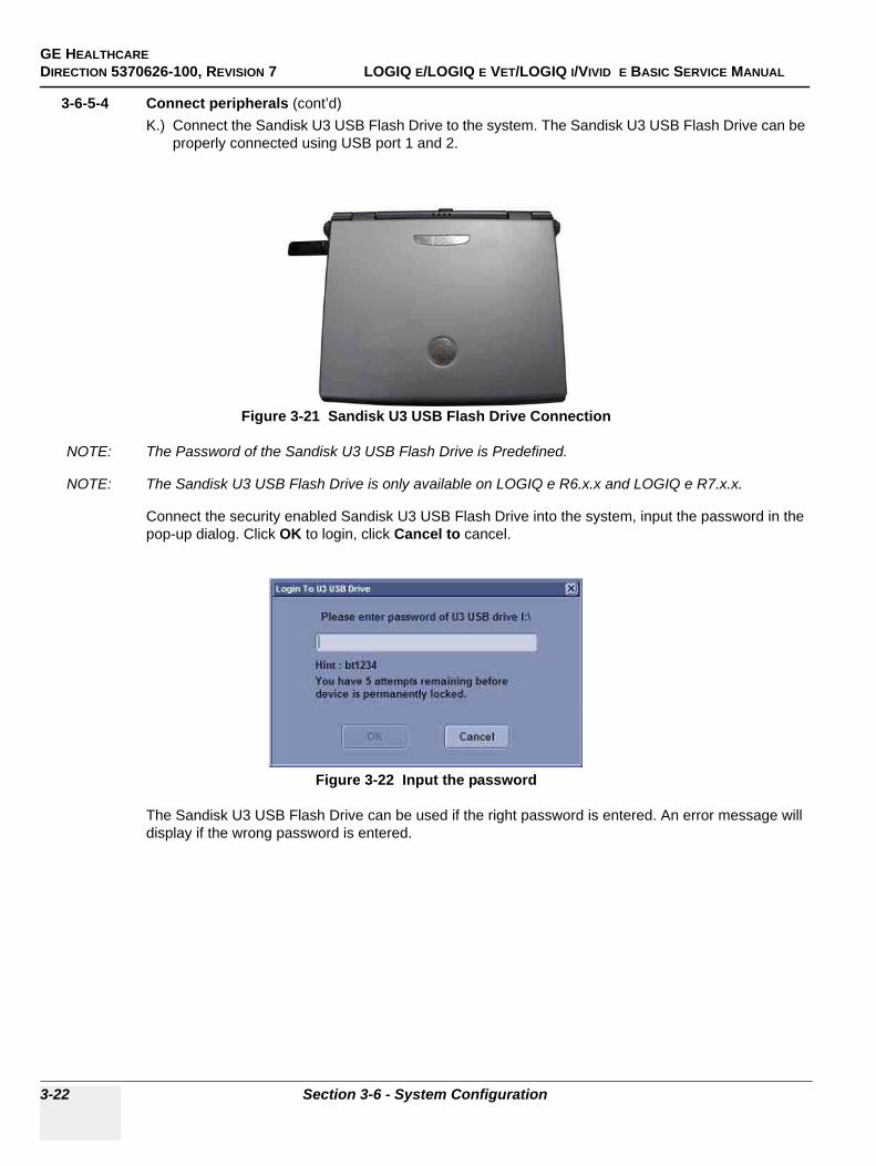
GE HEALTHCAREDIRECTION 5370626-100, REVISION 7 LOGIQ E/LOGIQ E VET/LOGIQ I/VIVID E BASIC SERVICE MANUAL
3-22 Section 3-6 - System Configuration
3-6-5-4 Connect peripherals (cont’d)K.) Connect the Sandisk U3 USB Flash Drive to the system. The Sandisk U3 USB Flash Drive can be
properly connected using USB port 1 and 2.
NOTE: The Password of the Sandisk U3 USB Flash Drive is Predefined.
NOTE: The Sandisk U3 USB Flash Drive is only available on LOGIQ e R6.x.x and LOGIQ e R7.x.x.
Connect the security enabled Sandisk U3 USB Flash Drive into the system, input the password in the pop-up dialog. Click OK to login, click Cancel to cancel.
The Sandisk U3 USB Flash Drive can be used if the right password is entered. An error message will display if the wrong password is entered.
Figure 3-21 Sandisk U3 USB Flash Drive Connection
Figure 3-22 Input the password
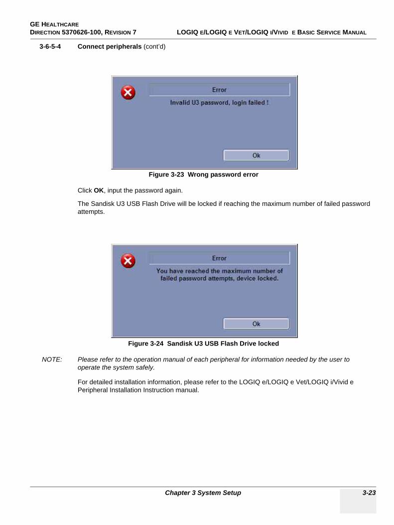
GE HEALTHCAREDIRECTION 5370626-100, REVISION 7 LOGIQ E/LOGIQ E VET/LOGIQ I/VIVID E BASIC SERVICE MANUAL
Chapter 3 System Setup 3-23
3-6-5-4 Connect peripherals (cont’d)
Click OK, input the password again.
The Sandisk U3 USB Flash Drive will be locked if reaching the maximum number of failed password attempts.
NOTE: Please refer to the operation manual of each peripheral for information needed by the user to operate the system safely.
For detailed installation information, please refer to the LOGIQ e/LOGIQ e Vet/LOGIQ i/Vivid e Peripheral Installation Instruction manual.
Figure 3-23 Wrong password error
Figure 3-24 Sandisk U3 USB Flash Drive locked
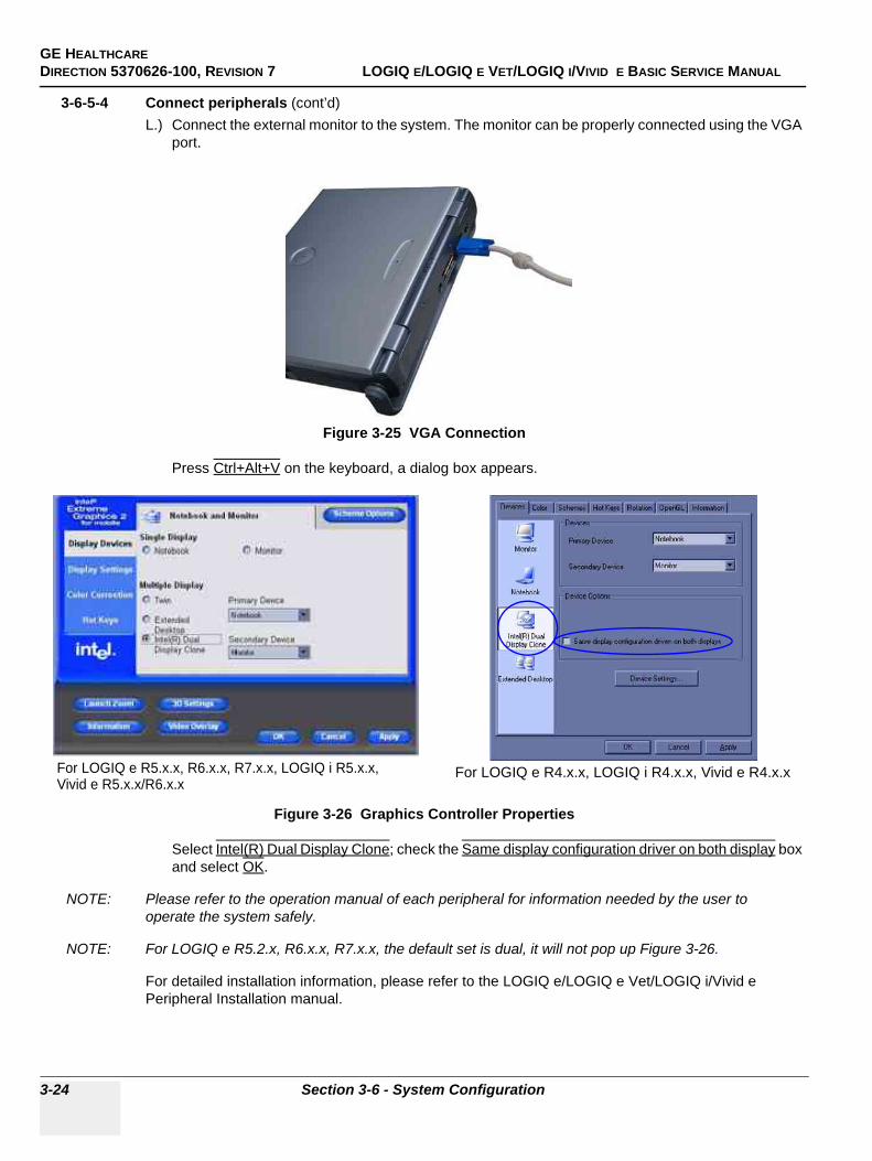
GE HEALTHCAREDIRECTION 5370626-100, REVISION 7 LOGIQ E/LOGIQ E VET/LOGIQ I/VIVID E BASIC SERVICE MANUAL
3-24 Section 3-6 - System Configuration
3-6-5-4 Connect peripherals (cont’d)L.) Connect the external monitor to the system. The monitor can be properly connected using the VGA
port.
Press Ctrl+Alt+V on the keyboard, a dialog box appears.
Select Intel(R) Dual Display Clone; check the Same display configuration driver on both display box and select OK.
NOTE: Please refer to the operation manual of each peripheral for information needed by the user to operate the system safely.
NOTE: For LOGIQ e R5.2.x, R6.x.x, R7.x.x, the default set is dual, it will not pop up Figure 3-26.
For detailed installation information, please refer to the LOGIQ e/LOGIQ e Vet/LOGIQ i/Vivid e Peripheral Installation manual.
Figure 3-25 VGA Connection
Figure 3-26 Graphics Controller Properties
For LOGIQ e R5.x.x, R6.x.x, R7.x.x, LOGIQ i R5.x.x, For LOGIQ e R4.x.x, LOGIQ i R4.x.x, Vivid e R4.x.xVivid e R5.x.x/R6.x.x

GE HEALTHCAREDIRECTION 5370626-100, REVISION 7 LOGIQ E/LOGIQ E VET/LOGIQ I/VIVID E BASIC SERVICE MANUAL
Chapter 3 System Setup 3-25
3-6-6 Available ProbesSee in specification in the LOGIQ e/LOGIQ e Vet/LOGIQ i/Vivid e User Reference Manual for Probes and intended use.
For LOGIQ e R4.0.x, the system supports 4C-RS, E8C-RS, 8C-RS, i12L-RS, 8L-RS, 3S-RS, 12L-RS Probes.
For LOGIQ e R5.0.x, the system supports 4C-RS, E8C-RS, 8C-RS, i12L-RS, 8L-RS, 3S-RS, 12L-RS, i/t739-RS, 9L-RS Probes.
For LOGIQ e R5.2.x, the system supports 4C-RS, E8C-RS, 8C-RS, i12L-RS, 8L-RS, 3S-RS, 12L-RS, i/t739-RS, 9L-RS, 16L-RS Probes.
For LOGIQ e R6.x.x, the system supports 4C-RS, E8C-RS, 8C-RS, i12L-RS, 8L-RS, 3S-RS, 12L-RS, i/t739-RS, 9L-RS, 16L-RS, 6Tc-RS, 6S-RS Probes.
For LOGIQ e R7.x.x, the system supports 4C-RS, E8C-RS, 8C-RS, i12L-RS, 8L-RS, 3S-RS, 12L-RS, i/t739-RS, 9L-RS, 16L-RS, 6Tc-RS, 6S-RS, L8-18i-RS,P2D Probes.
For LOGIQ i R4.x.x, the system supports 4C-RS, E8C-RS, 8C-RS, i12L-RS, 8L-RS, 3S-RS, 12L-RS Probes.
For LOGIQ i R5.x.x, the system supports 4C-RS, E8C-RS, 8C-RS, i12L-RS, 8L-RS, 3S-RS, 6S-RS, 12L-RS, i/t739-RS, P2D, 9L-RS Probes.
For Vivid e R4.x.x, the system supports 4C-RS, i12L-RS, 8L-RS, 3S-RS Probes.
For Vivid e R5.0.x, the system supports 4C-RS, i12L-RS, 8L-RS, 3S-RS, 8C-RS, 9L-RS, P2D Probes.
For Vivid e R5.2.x, the system supports 4C-RS, 8C-RS, E8C-RS, 8L-RS, 9L-RS, 12L-RS, i12L-RS, 3S-RS, 6S-RS, P2D Probes.
For Vivid e R6.x.x, the system supports 4C-RS, 8C-RS, E8C-RS, 8L-RS, 9L-RS, 12L-RS, i12L-RS, 3S-RS, 6S-RS, P2D, 6Tc-RS Probes.
For LOGIQ e Vet R5.0.x, the system supports 4C-RS Vet, E8C-RS Vet, 8C-RS Vet, i12L-RS Vet, 8L-RS Vet, 3S-RS Vet, 12L-RS Vet, 9L-RS Vet, i739-RS LC, 6S Vet-RS
For LOGIQ e Vet R5.2.x, the system supports 4C-RS Vet, E8C-RS Vet, 8C-RS Vet, i12L-RS Vet, 8L-RS Vet, 3S-RS Vet, 12L-RS Vet, 9L-RS Vet
For LOGIQ e Vet R6.x.x, the system supports 4C-RS Vet, E8C-RS Vet, 8C-RS Vet, i12L-RS Vet, 8L-RS Vet, 3S-RS Vet, 12L-RS Vet, 9L-RS Vet, 6S Vet-RS, i739-RS-LC, 6Tc-RS Vet
NOTE: 16L-RS is not available in China.
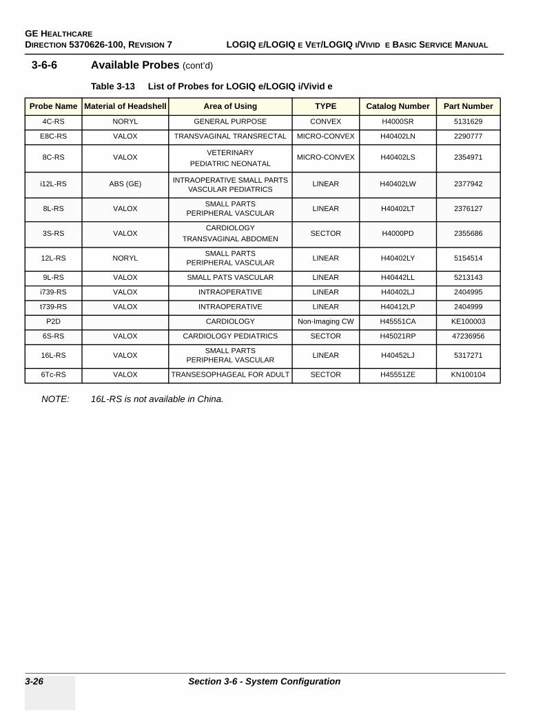
GE HEALTHCAREDIRECTION 5370626-100, REVISION 7 LOGIQ E/LOGIQ E VET/LOGIQ I/VIVID E BASIC SERVICE MANUAL
3-26 Section 3-6 - System Configuration
3-6-6 Available Probes (cont’d)
NOTE: 16L-RS is not available in China.
Table 3-13 List of Probes for LOGIQ e/LOGIQ i/Vivid e
Probe Name Material of Headshell Area of Using TYPE Catalog Number Part Number
4C-RS NORYL GENERAL PURPOSE CONVEX H4000SR 5131629
E8C-RS VALOX TRANSVAGINAL TRANSRECTAL MICRO-CONVEX H40402LN 2290777
8C-RS VALOX VETERINARYPEDIATRIC NEONATAL
MICRO-CONVEX H40402LS 2354971
i12L-RS ABS (GE) INTRAOPERATIVE SMALL PARTS VASCULAR PEDIATRICS
LINEAR H40402LW 2377942
8L-RS VALOX SMALL PARTSPERIPHERAL VASCULAR LINEAR H40402LT 2376127
3S-RS VALOXCARDIOLOGY
TRANSVAGINAL ABDOMENSECTOR H4000PD 2355686
12L-RS NORYL SMALL PARTSPERIPHERAL VASCULAR LINEAR H40402LY 5154514
9L-RS VALOX SMALL PATS VASCULAR LINEAR H40442LL 5213143
i739-RS VALOX INTRAOPERATIVE LINEAR H40402LJ 2404995
t739-RS VALOX INTRAOPERATIVE LINEAR H40412LP 2404999
P2D CARDIOLOGY Non-Imaging CW H45551CA KE100003
6S-RS VALOX CARDIOLOGY PEDIATRICS SECTOR H45021RP 47236956
16L-RS VALOX SMALL PARTS PERIPHERAL VASCULAR LINEAR H40452LJ 5317271
6Tc-RS VALOX TRANSESOPHAGEAL FOR ADULT SECTOR H45551ZE KN100104
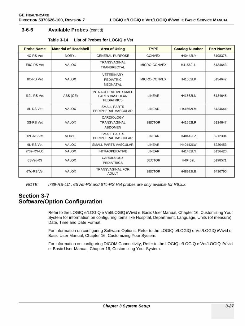
GE HEALTHCAREDIRECTION 5370626-100, REVISION 7 LOGIQ E/LOGIQ E VET/LOGIQ I/VIVID E BASIC SERVICE MANUAL
Chapter 3 System Setup 3-27
3-6-6 Available Probes (cont’d)
NOTE: i739-RS-LC , 6SVet-RS and 6Tc-RS Vet probes are only availble for R6.x.x.
Section 3-7Software/Option Configuration
Refer to the LOGIQ e/LOGIQ e Vet/LOGIQ i/Vivid e Basic User Manual, Chapter 16, Customizing Your System for information on configuring items like Hospital, Department, Language, Units (of measure), Date, Time and Date Format.
For information on configuring Software Options, Refer to the LOGIQ e/LOGIQ e Vet/LOGIQ i/Vivid e Basic User Manual, Chapter 16, Customizing Your System.
For information on configuring DICOM Connectivity, Refer to the LOGIQ e/LOGIQ e Vet/LOGIQ i/Vivid e Basic User Manual, Chapter 16, Customizing Your System.
Table 3-14 List of Probes for LOGIQ e Vet
Probe Name Material of Headshell Area of Using TYPE Catalog Number Part Number
4C-RS Vet NORYL GENERAL PURPOSE CONVEX H40442LY 5198378
E8C-RS Vet VALOXTRANSVAGINALTRANSRECTAL
MICRO-CONVEX H41562LL 5134643
8C-RS Vet VALOXVETERINARYPEDIATRICNEONATAL
MICRO-CONVEX H41562LK 5134642
i12L-RS Vet ABS (GE)INTRAOPERATIVE SMALL
PARTS VASCULAR PEDIATRICS
LINEAR H41562LN 5134645
8L-RS Vet VALOX SMALL PARTSPERIPHERAL VASCULAR LINEAR H41562LM 5134644
3S-RS Vet VALOXCARDIOLOGY
TRANSVAGINALABDOMEN
SECTOR H41562LR 5134647
12L-RS Vet NORYL SMALL PARTSPERIPHERAL VASCULAR LINEAR H40442LZ 5212304
9L-RS Vet VALOX SMALL PARTS VASCULAR LINEAR H40442LW 5220453
i739-RS-LC VALOX INTRAOPERATIVE LINEAR H41482LS 5136420
6SVet-RS VALOXCARDIOLOGYPEDIATRICS
SECTOR H40452L 5198571
6Tc-RS Vet VALOX TRANSVAGINAL FOR ADULT SECTOR H48922LB 5430790
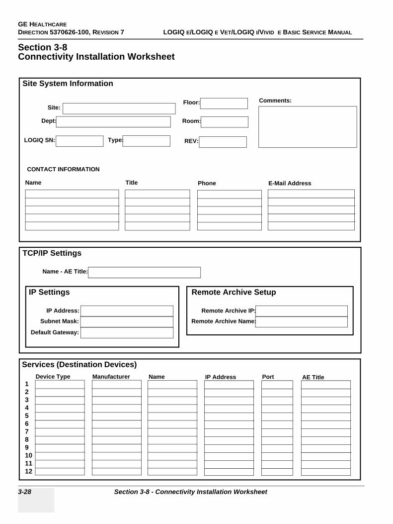
GE HEALTHCAREDIRECTION 5370626-100, REVISION 7 LOGIQ E/LOGIQ E VET/LOGIQ I/VIVID E BASIC SERVICE MANUAL
3-28 Section 3-8 - Connectivity Installation Worksheet
Section 3-8Connectivity Installation Worksheet
Site System Information
Services (Destination Devices)
TCP/IP Settings
Device Type Manufacturer Name IP Address Port AE Title123456789101112
Name - AE Title:
Dept:
LOGIQ SN: Type:
Floor:
Room:
REV:
Comments:
CONTACT INFORMATION
Name Title Phone E-Mail Address
Site:
IP Settings
IP Address:
Subnet Mask:
Default Gateway:
Remote Archive Setup
Remote Archive IP:
Remote Archive Name:
GE HEALTHCAREDIRECTION 5370626-100, REVISION 7 LOGIQ E/LOGIQ E VET/LOGIQ I/VIVID E BASIC SERVICE MANUAL
Chapter 3 System Setup 3-29
Section 3-9Loading Base Image Software
This information has been moved, please refer to:
Section 8-3 "Loading Base Image Software" on page 8-4
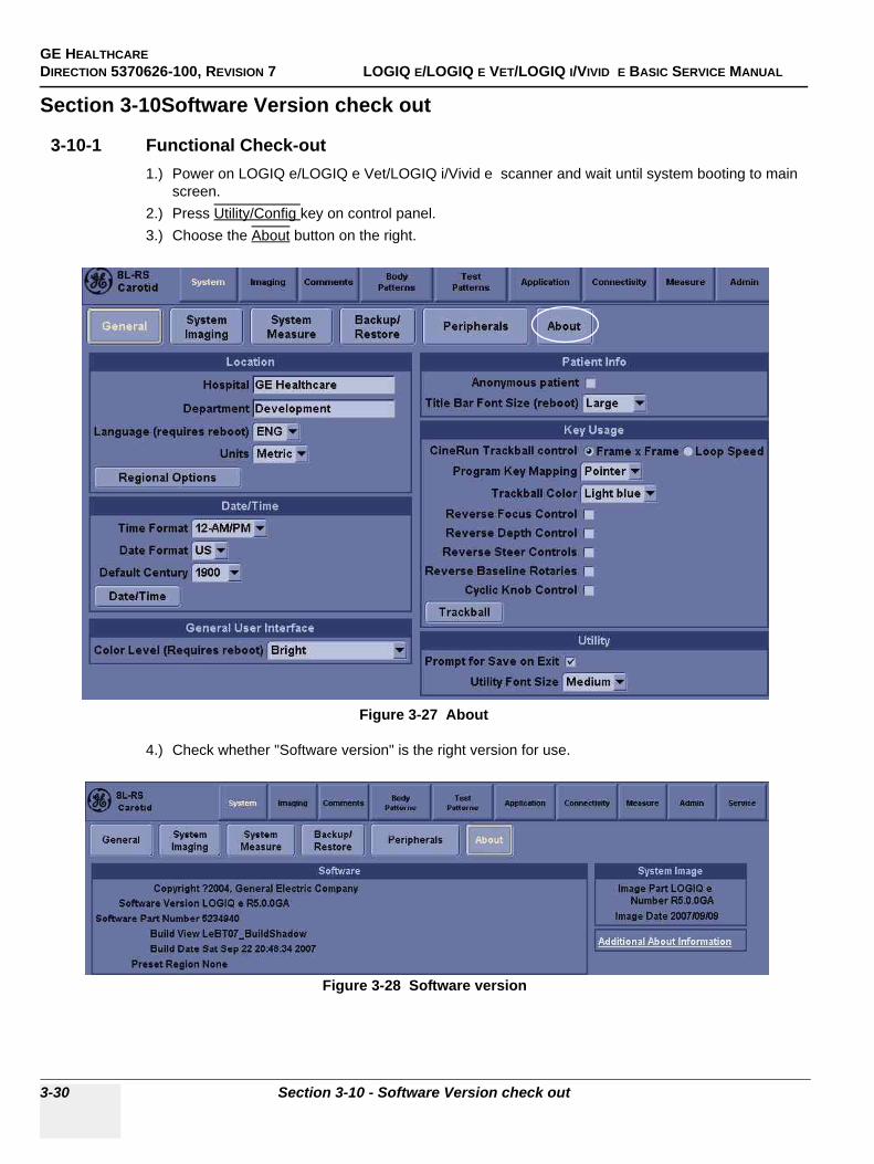
GE HEALTHCAREDIRECTION 5370626-100, REVISION 7 LOGIQ E/LOGIQ E VET/LOGIQ I/VIVID E BASIC SERVICE MANUAL
3-30 Section 3-10 - Software Version check out
Section 3-10Software Version check out
3-10-1 Functional Check-out1.) Power on LOGIQ e/LOGIQ e Vet/LOGIQ i/Vivid e scanner and wait until system booting to main
screen.2.) Press Utility/Config key on control panel.3.) Choose the About button on the right.
4.) Check whether "Software version" is the right version for use.
Figure 3-27 About
Figure 3-28 Software version
GE HEALTHCAREDIRECTION 5370626-100, REVISION 7 LOGIQ E/LOGIQ E VET/LOGIQ I/VIVID E BASIC SERVICE MANUAL
Chapter 3 System Setup 3-31
Section 3-11Paperwork
NOTE: During and after installation, the documentation (i.e. User Manuals, Installation Manuals...) for the peripheral units must be kept as part of the original system documentation. This will ensure that all relevant safety and user information is available during the operation and service of the complete system.
3-11-1 Product Locator Installation
NOTE: The Product Locator Installation Card shown may not be same as the provided Product Locator card.
3-11-2 User Manual(s)User Check that the correct User Manual(s) for the system and software revision, is included with the installation. Specific language versions of the User Manual may also be available. Check with your GE Sales Representative for availability.
Figure 3-29 Product Locator Installation Card

GE HEALTHCAREDIRECTION 5370626-100, REVISION 7 LOGIQ E/LOGIQ E VET/LOGIQ I/VIVID E BASIC SERVICE MANUAL
3-32 Section 3-11 - Paperwork
This page was intentionally left blank.
GE HEALTHCARE DIRECTION 5370626-100, REVISION 7 LOGIQ E/LOGIQ E VET/LOGIQ I/VIVID E BASIC SERVICE MANUAL
Chapter 4 Functional Checks 4-1
Chapter 4Functional Checks
Section 4-1Overview
4-1-1 Purpose for Chapter 4This chapter provides procedures for quickly checking major functions of the LOGIQ e/LOGIQ e Vet/LOGIQ i/Vivid e console, diagnostics by using the built-in service software, and power supply adjustments.
Section 4-2Required Equipment
To perform these tests, you'll need any of the sector, linear, or convex transducers.
(normally you should check all the transducers used on the system)
Table 4-1 Contents in chapter 4
Section Description Page Number
4-1 Overview 4-1
4-2 Required Equipment 4-1
4-3 General Procedure 4-2
4-4 Software Configuration Checks 4-37
4-5 Peripheral Checks 4-37
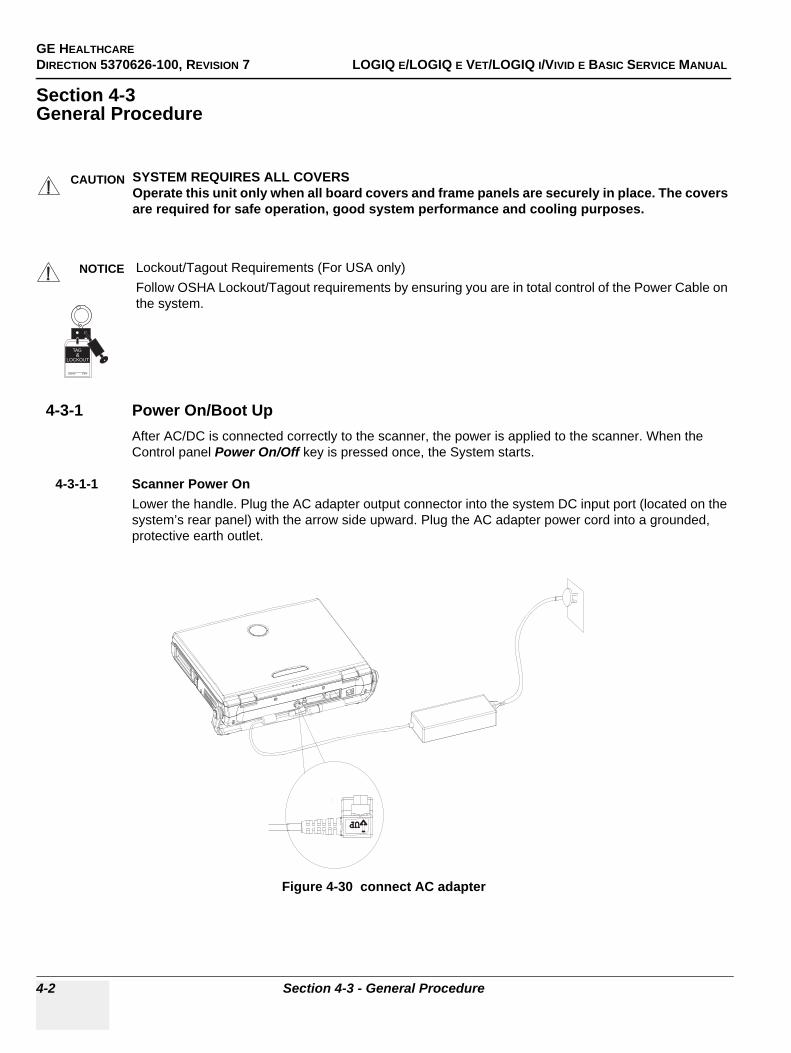
GE HEALTHCAREDIRECTION 5370626-100, REVISION 7 LOGIQ E/LOGIQ E VET/LOGIQ I/VIVID E BASIC SERVICE MANUAL
4-2 Section 4-3 - General Procedure
Section 4-3General Procedure
4-3-1 Power On/Boot UpAfter AC/DC is connected correctly to the scanner, the power is applied to the scanner. When the Control panel Power On/Off key is pressed once, the System starts.
4-3-1-1 Scanner Power OnLower the handle. Plug the AC adapter output connector into the system DC input port (located on the system’s rear panel) with the arrow side upward. Plug the AC adapter power cord into a grounded, protective earth outlet.
CAUTION SYSTEM REQUIRES ALL COVERSOperate this unit only when all board covers and frame panels are securely in place. The covers are required for safe operation, good system performance and cooling purposes.
NOTICE Lockout/Tagout Requirements (For USA only)Follow OSHA Lockout/Tagout requirements by ensuring you are in total control of the Power Cable on the system.
Figure 4-30 connect AC adapter
Signed Date
TAG &
LOCKOUT
UPUP
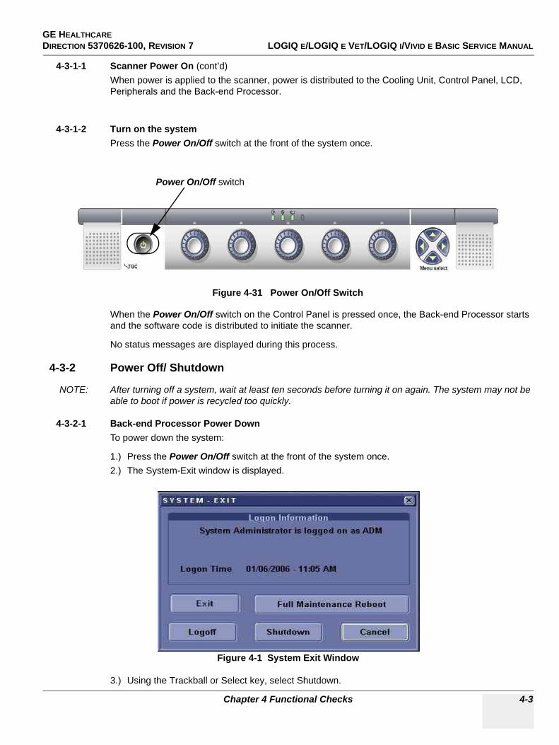
GE HEALTHCARE DIRECTION 5370626-100, REVISION 7 LOGIQ E/LOGIQ E VET/LOGIQ I/VIVID E BASIC SERVICE MANUAL
Chapter 4 Functional Checks 4-3
4-3-1-1 Scanner Power On (cont’d)When power is applied to the scanner, power is distributed to the Cooling Unit, Control Panel, LCD, Peripherals and the Back-end Processor.
4-3-1-2 Turn on the systemPress the Power On/Off switch at the front of the system once.
When the Power On/Off switch on the Control Panel is pressed once, the Back-end Processor starts and the software code is distributed to initiate the scanner.
No status messages are displayed during this process.
4-3-2 Power Off/ Shutdown
NOTE: After turning off a system, wait at least ten seconds before turning it on again. The system may not be able to boot if power is recycled too quickly.
4-3-2-1 Back-end Processor Power DownTo power down the system:
1.) Press the Power On/Off switch at the front of the system once.2.) The System-Exit window is displayed.
3.) Using the Trackball or Select key, select Shutdown.
Figure 4-31 Power On/Off Switch
Figure 4-1 System Exit Window
Power On/Off switch
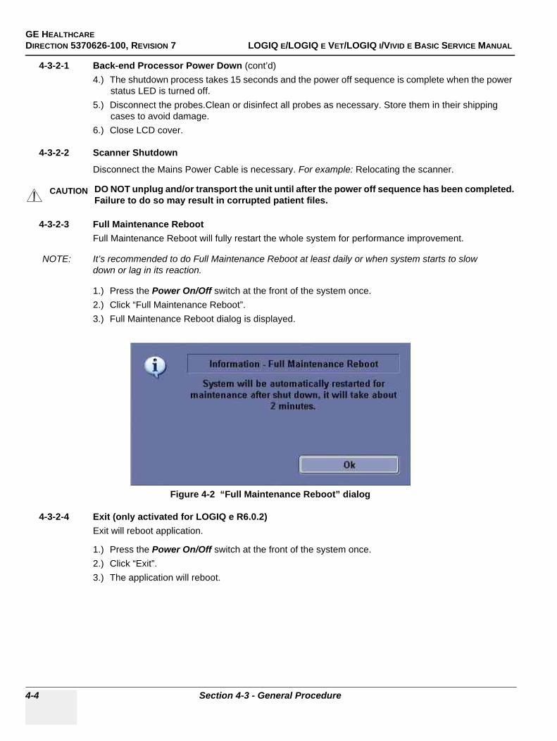
GE HEALTHCAREDIRECTION 5370626-100, REVISION 7 LOGIQ E/LOGIQ E VET/LOGIQ I/VIVID E BASIC SERVICE MANUAL
4-4 Section 4-3 - General Procedure
4-3-2-1 Back-end Processor Power Down (cont’d)4.) The shutdown process takes 15 seconds and the power off sequence is complete when the power
status LED is turned off.5.) Disconnect the probes.Clean or disinfect all probes as necessary. Store them in their shipping
cases to avoid damage.6.) Close LCD cover.
4-3-2-2 Scanner Shutdown
Disconnect the Mains Power Cable is necessary. For example: Relocating the scanner.
4-3-2-3 Full Maintenance RebootFull Maintenance Reboot will fully restart the whole system for performance improvement.
NOTE: It’s recommended to do Full Maintenance Reboot at least daily or when system starts to slow down or lag in its reaction.
1.) Press the Power On/Off switch at the front of the system once.2.) Click “Full Maintenance Reboot”.3.) Full Maintenance Reboot dialog is displayed.
4-3-2-4 Exit (only activated for LOGIQ e R6.0.2)Exit will reboot application.
1.) Press the Power On/Off switch at the front of the system once.2.) Click “Exit”.3.) The application will reboot.
CAUTION DO NOT unplug and/or transport the unit until after the power off sequence has been completed. Failure to do so may result in corrupted patient files.
Figure 4-2 “Full Maintenance Reboot” dialog
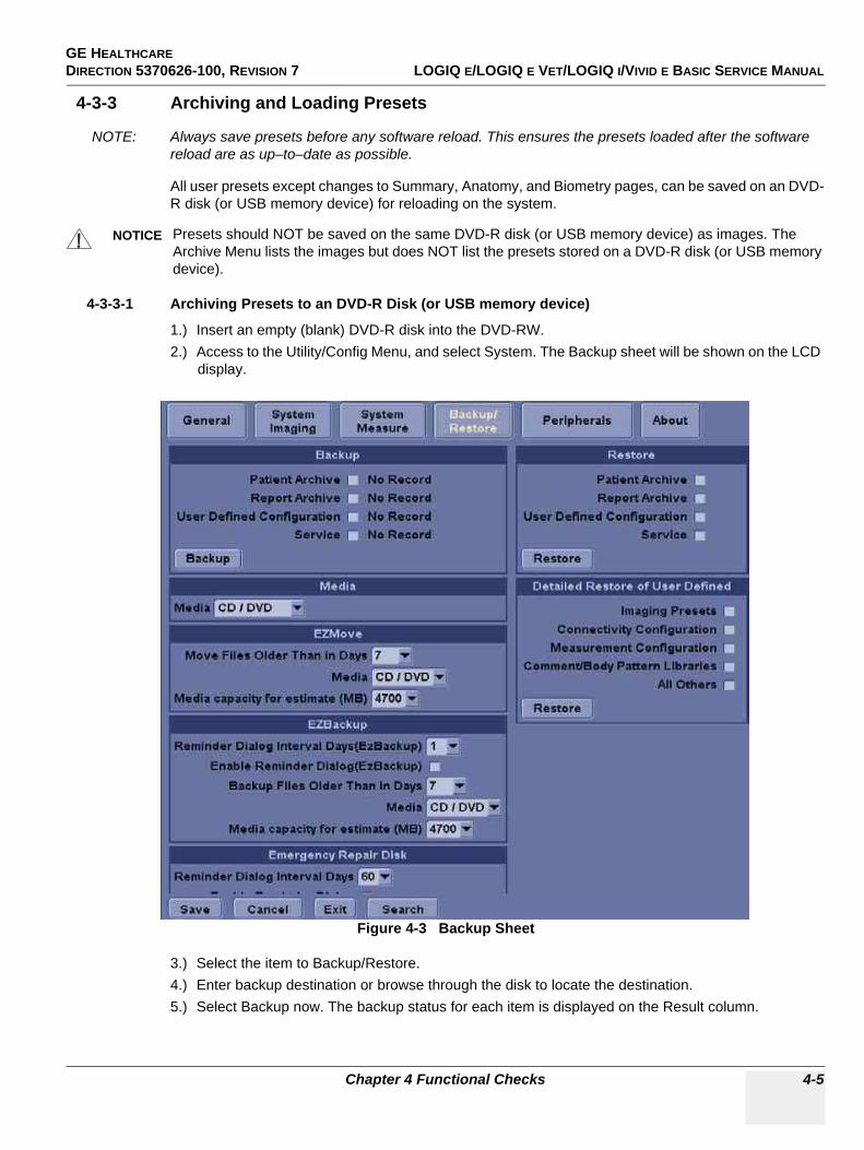
GE HEALTHCARE DIRECTION 5370626-100, REVISION 7 LOGIQ E/LOGIQ E VET/LOGIQ I/VIVID E BASIC SERVICE MANUAL
Chapter 4 Functional Checks 4-5
4-3-3 Archiving and Loading Presets
NOTE: Always save presets before any software reload. This ensures the presets loaded after the software reload are as up–to–date as possible.
All user presets except changes to Summary, Anatomy, and Biometry pages, can be saved on an DVD-R disk (or USB memory device) for reloading on the system.
4-3-3-1 Archiving Presets to an DVD-R Disk (or USB memory device)
1.) Insert an empty (blank) DVD-R disk into the DVD-RW.2.) Access to the Utility/Config Menu, and select System. The Backup sheet will be shown on the LCD
display.
3.) Select the item to Backup/Restore.4.) Enter backup destination or browse through the disk to locate the destination.5.) Select Backup now. The backup status for each item is displayed on the Result column.
NOTICE Presets should NOT be saved on the same DVD-R disk (or USB memory device) as images. The Archive Menu lists the images but does NOT list the presets stored on a DVD-R disk (or USB memory device).
Figure 4-3 Backup Sheet
GE HEALTHCAREDIRECTION 5370626-100, REVISION 7 LOGIQ E/LOGIQ E VET/LOGIQ I/VIVID E BASIC SERVICE MANUAL
4-6 Section 4-3 - General Procedure
4-3-3-2 Loading Presets from an DVD-R disk (or USB memory device)
1.) Insert the DVD-R disk with the archived Presets into the DVD-RW.2.) Access to the Utility/Config Menu, and select System. The Restore sheet will be shown on the LCD
display. (see Figure 4-3 on page 4-5 )3.) Select the item to restore either from Resource Files.4.) Enter restore destination or browse through the disk to locate the destination.5.) Select Restore. The restore status for each item is displayed on the Result column.
4-3-4 Adjusting the Display MonitorPlease refer to Section 6-2 "Monitor Adjustments" on page 6-2.
4-3-5 Lockout/Tagout (LOTO) requirementsFollow OSHA Lockout/Tagout requirements (USA) or local Lockout/Tagout requirements by ensuring you are in total control of the AC power plug at all times during the service process.
To apply Lockout/Tagout:
1.) Plan and prepare for shutdown.2.) Shutdown the equipment.3.) Isolate the equipment.4.) Apply Lockout/Tagout Devices.5.) Remove battery.6.) Control all stored and residual energy.7.) Verify isolation.
All potentially hazardous stored or residual energy is relieved.
NOTICE Energy Control and Power Lockout for LOGIQ e/LOGIQ e Vet/LOGIQ i/Vivid e WHEN SERVICING PARTS OF THE SYSTEM WHERE THERE IS EXPOSURE TO VOLTAGE GREATER THAN 30 VOLTS:1. TURN OFF THE SCANNER.2. UNPLUG THE SYSTEM.3. MAINTAIN CONTROL OF THE SYSTEM POWER PLUG.4. WAIT FOR AT LEAST 20 SECONDS FOR CAPACITORS TO DISCHARGE AS THERE ARE NO TEST POINTS TO VERIFY ISOLATION. THE AMBER LIGHT ON THE OP PANEL ON/OFF BUTTON WILL TURN OFF.5. REMOVE THE SYSTEM BATTERY.Signed Date
TAG &
LOCKOUT
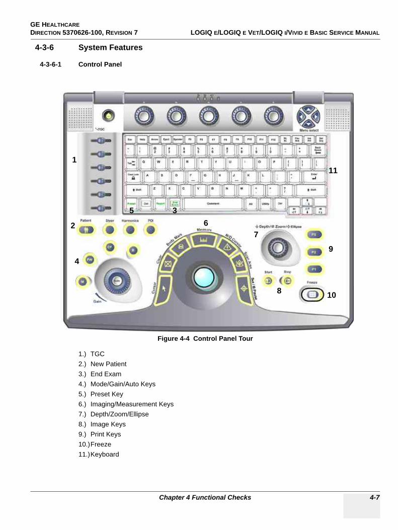
GE HEALTHCARE DIRECTION 5370626-100, REVISION 7 LOGIQ E/LOGIQ E VET/LOGIQ I/VIVID E BASIC SERVICE MANUAL
Chapter 4 Functional Checks 4-7
4-3-6 System Features
4-3-6-1 Control Panel
1.) TGC2.) New Patient3.) End Exam4.) Mode/Gain/Auto Keys5.) Preset Key6.) Imaging/Measurement Keys7.) Depth/Zoom/Ellipse8.) Image Keys9.) Print Keys10.)Freeze11.)Keyboard
Figure 4-4 Control Panel Tour
1
2
3
4
56
7
8
9
10
11
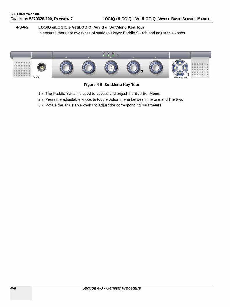
GE HEALTHCAREDIRECTION 5370626-100, REVISION 7 LOGIQ E/LOGIQ E VET/LOGIQ I/VIVID E BASIC SERVICE MANUAL
4-8 Section 4-3 - General Procedure
4-3-6-2 LOGIQ e/LOGIQ e Vet/LOGIQ i/Vivid e SoftMenu Key TourIn general, there are two types of softMenu keys: Paddle Switch and adjustable knobs.
1.) The Paddle Switch is used to access and adjust the Sub SoftMenu.2.) Press the adjustable knobs to toggle option menu between line one and line two.3.) Rotate the adjustable knobs to adjust the corresponding parameters.
Figure 4-5 SoftMenu Key Tour
21
3
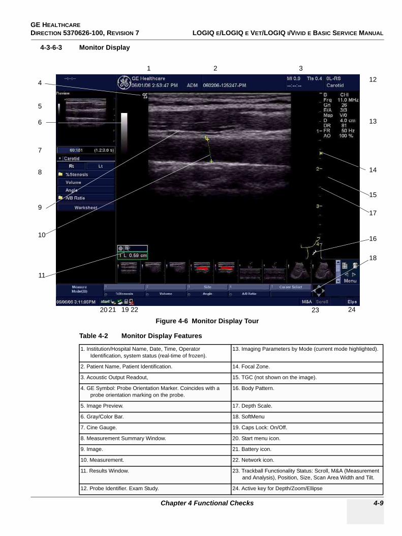
GE HEALTHCARE DIRECTION 5370626-100, REVISION 7 LOGIQ E/LOGIQ E VET/LOGIQ I/VIVID E BASIC SERVICE MANUAL
Chapter 4 Functional Checks 4-9
4-3-6-3 Monitor Display
Figure 4-6 Monitor Display Tour
Table 4-2 Monitor Display Features
1. Institution/Hospital Name, Date, Time, Operator Identification, system status (real-time of frozen).
13. Imaging Parameters by Mode (current mode highlighted).
2. Patient Name, Patient Identification. 14. Focal Zone.
3. Acoustic Output Readout, 15. TGC (not shown on the image).
4. GE Symbol: Probe Orientation Marker. Coincides with a probe orientation marking on the probe.
16. Body Pattern.
5. Image Preview. 17. Depth Scale.
6. Gray/Color Bar. 18. SoftMenu
7. Cine Gauge. 19. Caps Lock: On/Off.
8. Measurement Summary Window. 20. Start menu icon.
9. Image. 21. Battery icon.
10. Measurement. 22. Network icon.
11. Results Window. 23. Trackball Functionality Status: Scroll, M&A (Measurement and Analysis), Position, Size, Scan Area Width and Tilt.
12. Probe Identifier. Exam Study. 24. Active key for Depth/Zoom/Ellipse
4
5
6
7
8
9
10
11
1920 21 22
18
12
16
17
15
14
13
23
1 2 3
24
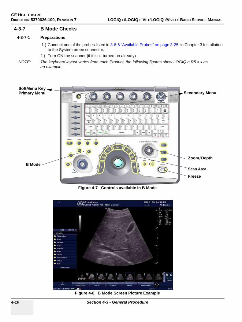
GE HEALTHCAREDIRECTION 5370626-100, REVISION 7 LOGIQ E/LOGIQ E VET/LOGIQ I/VIVID E BASIC SERVICE MANUAL
4-10 Section 4-3 - General Procedure
4-3-7 B Mode Checks4-3-7-1 Preparations
1.) Connect one of the probes listed in 3-6-6 "Available Probes" on page 3-25, in Chapter 3 Installation to the System probe connector.
2.) Turn ON the scanner (if it isn’t turned on already)NOTE: The keyboard layout varies from each Product, the following figures show LOGIQ e R5.x.x as
an example.
Figure 4-7 Controls available in B Mode
Figure 4-8 B Mode Screen Picture Example
SoftMenu KeyPrimary Menu
Scan AreaB Mode
Zoom/Depth
Freeze
Secondary Menu
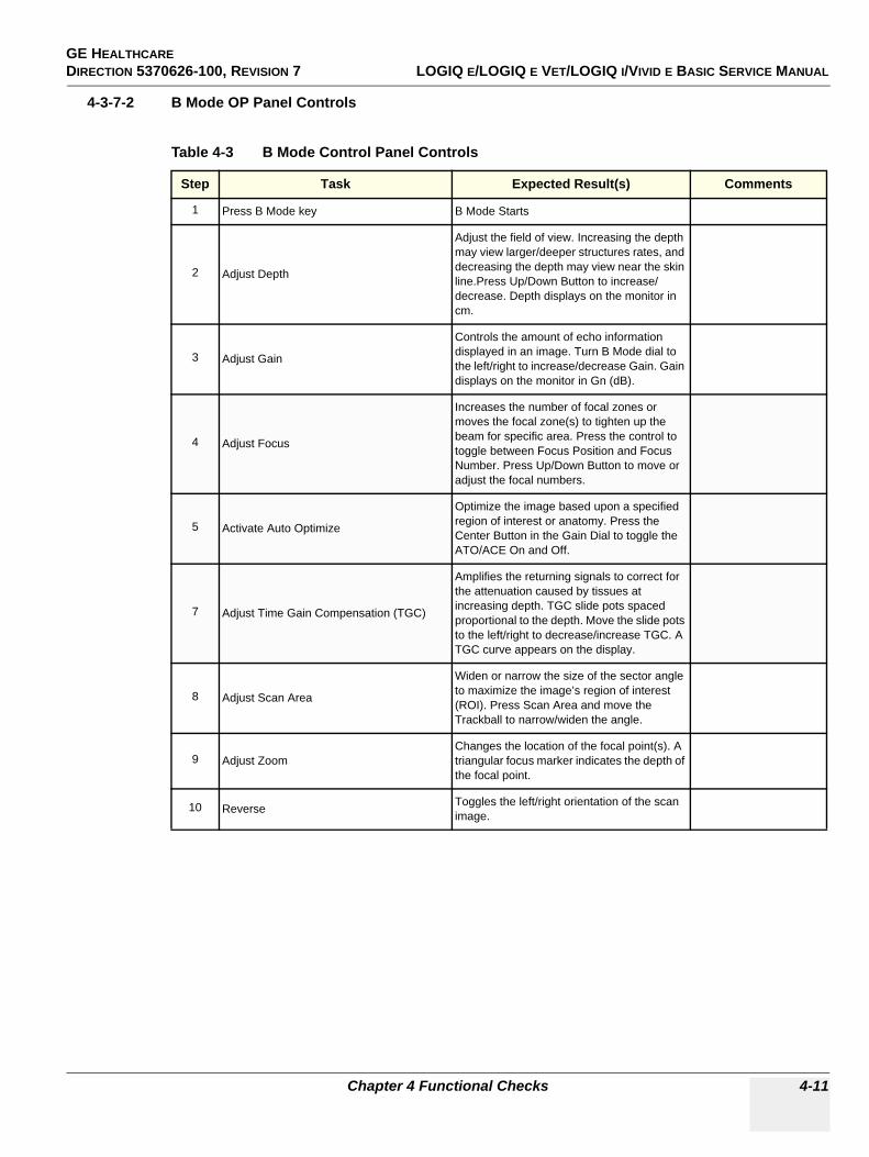
GE HEALTHCARE DIRECTION 5370626-100, REVISION 7 LOGIQ E/LOGIQ E VET/LOGIQ I/VIVID E BASIC SERVICE MANUAL
Chapter 4 Functional Checks 4-11
4-3-7-2 B Mode OP Panel Controls
Table 4-3 B Mode Control Panel Controls
Step Task Expected Result(s) Comments
1 Press B Mode key B Mode Starts
2 Adjust Depth
Adjust the field of view. Increasing the depth may view larger/deeper structures rates, and decreasing the depth may view near the skin line.Press Up/Down Button to increase/decrease. Depth displays on the monitor in cm.
3 Adjust Gain
Controls the amount of echo information displayed in an image. Turn B Mode dial to the left/right to increase/decrease Gain. Gain displays on the monitor in Gn (dB).
4 Adjust Focus
Increases the number of focal zones or moves the focal zone(s) to tighten up the beam for specific area. Press the control to toggle between Focus Position and Focus Number. Press Up/Down Button to move or adjust the focal numbers.
5 Activate Auto Optimize
Optimize the image based upon a specified region of interest or anatomy. Press the Center Button in the Gain Dial to toggle the ATO/ACE On and Off.
7 Adjust Time Gain Compensation (TGC)
Amplifies the returning signals to correct for the attenuation caused by tissues at increasing depth. TGC slide pots spaced proportional to the depth. Move the slide pots to the left/right to decrease/increase TGC. A TGC curve appears on the display.
8 Adjust Scan Area
Widen or narrow the size of the sector angle to maximize the image’s region of interest (ROI). Press Scan Area and move the Trackball to narrow/widen the angle.
9 Adjust ZoomChanges the location of the focal point(s). A triangular focus marker indicates the depth of the focal point.
10 Reverse Toggles the left/right orientation of the scan image.
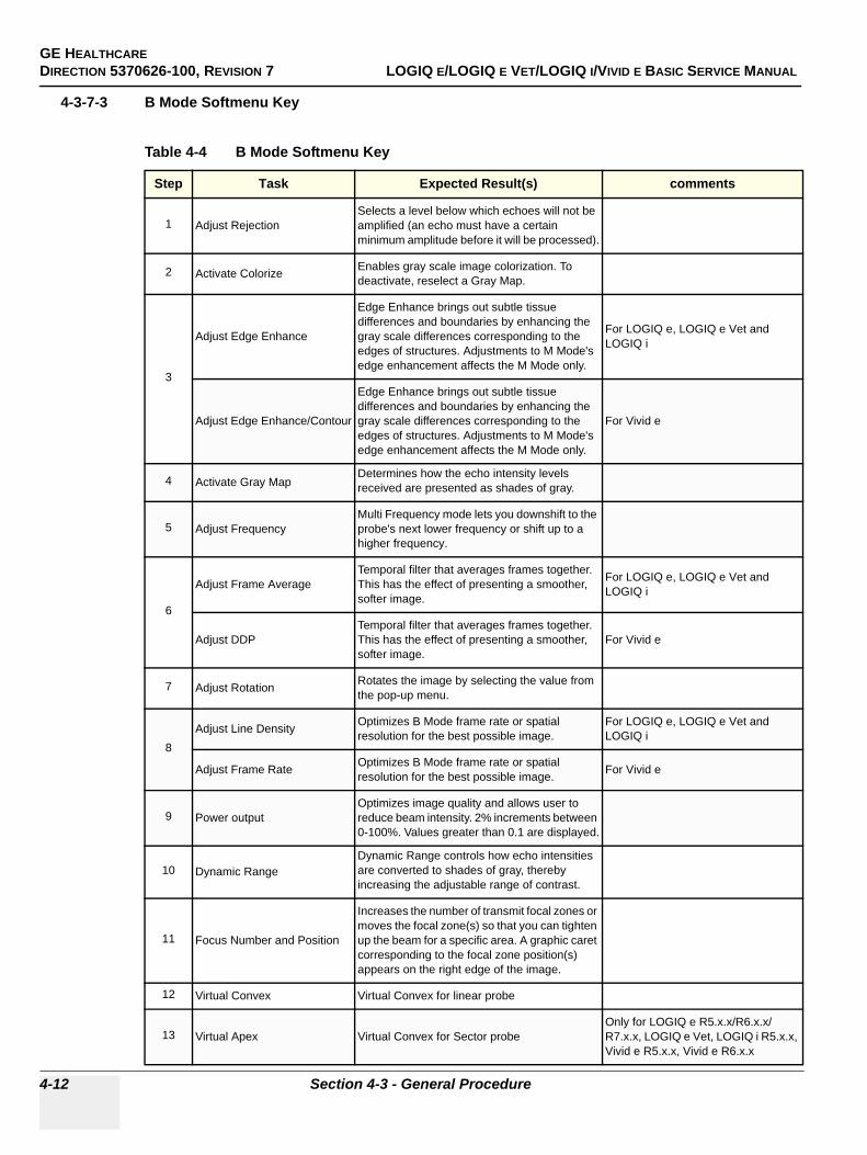
GE HEALTHCAREDIRECTION 5370626-100, REVISION 7 LOGIQ E/LOGIQ E VET/LOGIQ I/VIVID E BASIC SERVICE MANUAL
4-12 Section 4-3 - General Procedure
4-3-7-3 B Mode Softmenu Key
Table 4-4 B Mode Softmenu Key
Step Task Expected Result(s) comments
1 Adjust RejectionSelects a level below which echoes will not be amplified (an echo must have a certain minimum amplitude before it will be processed).
2 Activate Colorize Enables gray scale image colorization. To deactivate, reselect a Gray Map.
3
Adjust Edge Enhance
Edge Enhance brings out subtle tissue differences and boundaries by enhancing the gray scale differences corresponding to the edges of structures. Adjustments to M Mode's edge enhancement affects the M Mode only.
For LOGIQ e, LOGIQ e Vet and LOGIQ i
Adjust Edge Enhance/Contour
Edge Enhance brings out subtle tissue differences and boundaries by enhancing the gray scale differences corresponding to the edges of structures. Adjustments to M Mode's edge enhancement affects the M Mode only.
For Vivid e
4 Activate Gray MapDetermines how the echo intensity levels received are presented as shades of gray.
5 Adjust FrequencyMulti Frequency mode lets you downshift to the probe's next lower frequency or shift up to a higher frequency.
6
Adjust Frame AverageTemporal filter that averages frames together. This has the effect of presenting a smoother, softer image.
For LOGIQ e, LOGIQ e Vet and LOGIQ i
Adjust DDPTemporal filter that averages frames together. This has the effect of presenting a smoother, softer image.
For Vivid e
7 Adjust Rotation Rotates the image by selecting the value from the pop-up menu.
8Adjust Line Density Optimizes B Mode frame rate or spatial
resolution for the best possible image.For LOGIQ e, LOGIQ e Vet and LOGIQ i
Adjust Frame Rate Optimizes B Mode frame rate or spatial resolution for the best possible image. For Vivid e
9 Power outputOptimizes image quality and allows user to reduce beam intensity. 2% increments between 0-100%. Values greater than 0.1 are displayed.
10 Dynamic RangeDynamic Range controls how echo intensities are converted to shades of gray, thereby increasing the adjustable range of contrast.
11 Focus Number and Position
Increases the number of transmit focal zones or moves the focal zone(s) so that you can tighten up the beam for a specific area. A graphic caret corresponding to the focal zone position(s) appears on the right edge of the image.
12 Virtual Convex Virtual Convex for linear probe
13 Virtual Apex Virtual Convex for Sector probeOnly for LOGIQ e R5.x.x/R6.x.x/R7.x.x, LOGIQ e Vet, LOGIQ i R5.x.x, Vivid e R5.x.x, Vivid e R6.x.x
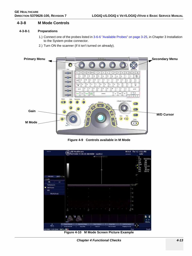
GE HEALTHCARE DIRECTION 5370626-100, REVISION 7 LOGIQ E/LOGIQ E VET/LOGIQ I/VIVID E BASIC SERVICE MANUAL
Chapter 4 Functional Checks 4-13
4-3-8 M Mode Controls
4-3-8-1 Preparations
1.) Connect one of the probes listed in 3-6-6 "Available Probes" on page 3-25, in Chapter 3 Installation to the System probe connector.
2.) Turn ON the scanner (if it isn’t turned on already).
Figure 4-9 Controls available in M Mode
Figure 4-10 M Mode Screen Picture Example
Primary Menu Secondary Menu
M Mode
GainM/D Cursor
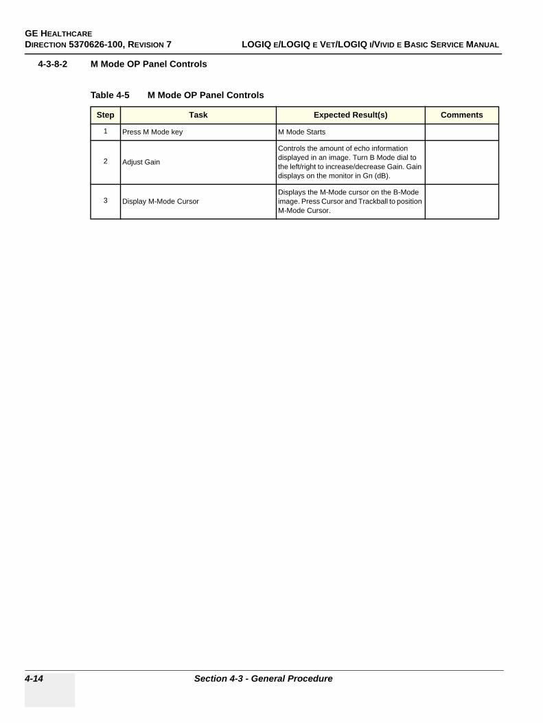
GE HEALTHCAREDIRECTION 5370626-100, REVISION 7 LOGIQ E/LOGIQ E VET/LOGIQ I/VIVID E BASIC SERVICE MANUAL
4-14 Section 4-3 - General Procedure
4-3-8-2 M Mode OP Panel Controls
Table 4-5 M Mode OP Panel Controls
Step Task Expected Result(s) Comments
1 Press M Mode key M Mode Starts
2 Adjust Gain
Controls the amount of echo information displayed in an image. Turn B Mode dial to the left/right to increase/decrease Gain. Gain displays on the monitor in Gn (dB).
3 Display M-Mode CursorDisplays the M-Mode cursor on the B-Mode image. Press Cursor and Trackball to position M-Mode Cursor.
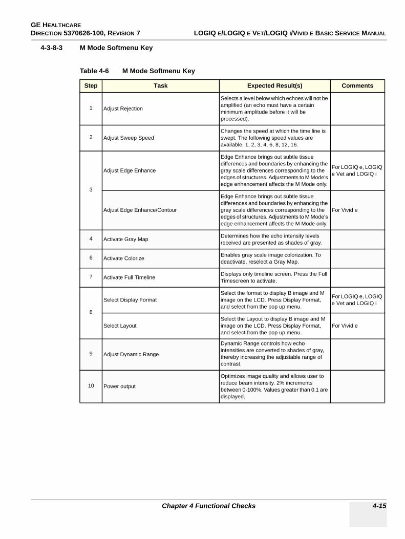
GE HEALTHCARE DIRECTION 5370626-100, REVISION 7 LOGIQ E/LOGIQ E VET/LOGIQ I/VIVID E BASIC SERVICE MANUAL
Chapter 4 Functional Checks 4-15
4-3-8-3 M Mode Softmenu Key
Table 4-6 M Mode Softmenu Key
Step Task Expected Result(s) Comments
1 Adjust Rejection
Selects a level below which echoes will not be amplified (an echo must have a certain minimum amplitude before it will be processed).
2 Adjust Sweep SpeedChanges the speed at which the time line is swept. The following speed values are available, 1, 2, 3, 4, 6, 8, 12, 16.
3
Adjust Edge Enhance
Edge Enhance brings out subtle tissue differences and boundaries by enhancing the gray scale differences corresponding to the edges of structures. Adjustments to M Mode's edge enhancement affects the M Mode only.
For LOGIQ e, LOGIQ e Vet and LOGIQ i
Adjust Edge Enhance/Contour
Edge Enhance brings out subtle tissue differences and boundaries by enhancing the gray scale differences corresponding to the edges of structures. Adjustments to M Mode's edge enhancement affects the M Mode only.
For Vivid e
4 Activate Gray Map Determines how the echo intensity levels received are presented as shades of gray.
6 Activate Colorize Enables gray scale image colorization. To deactivate, reselect a Gray Map.
7 Activate Full Timeline Displays only timeline screen. Press the Full Timescreen to activate.
8
Select Display FormatSelect the format to display B image and M image on the LCD. Press Display Format, and select from the pop up menu.
For LOGIQ e, LOGIQ e Vet and LOGIQ i
Select LayoutSelect the Layout to display B image and M image on the LCD. Press Display Format, and select from the pop up menu.
For Vivid e
9 Adjust Dynamic Range
Dynamic Range controls how echo intensities are converted to shades of gray, thereby increasing the adjustable range of contrast.
10 Power output
Optimizes image quality and allows user to reduce beam intensity. 2% increments between 0-100%. Values greater than 0.1 are displayed.

GE HEALTHCAREDIRECTION 5370626-100, REVISION 7 LOGIQ E/LOGIQ E VET/LOGIQ I/VIVID E BASIC SERVICE MANUAL
4-16 Section 4-3 - General Procedure
4-3-9 Color Flow Mode Checks
4-3-9-1 Preparations
1.) Connect one of the probes listed in 3-6-6 "Available Probes" on page 3-25, in Chapter 3 Installation to the System probe connector.
2.) Turn ON the scanner (if it isn’t turned on already).
Figure 4-11 Controls available in Color Flow Mode
Figure 4-12 CFM Mode Screen Picture Example
Primary Menu
CF Mode
Gain
Secondary Menu
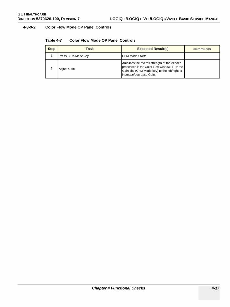
GE HEALTHCARE DIRECTION 5370626-100, REVISION 7 LOGIQ E/LOGIQ E VET/LOGIQ I/VIVID E BASIC SERVICE MANUAL
Chapter 4 Functional Checks 4-17
4-3-9-2 Color Flow Mode OP Panel Controls
Table 4-7 Color Flow Mode OP Panel Controls
Step Task Expected Result(s) comments
1 Press CFM-Mode key CFM Mode Starts
2 Adjust Gain
Amplifies the overall strength of the echoes processed in the Color Flow window. Turn the Gain dial (CFM Mode key) to the left/right to increase/decrease Gain.
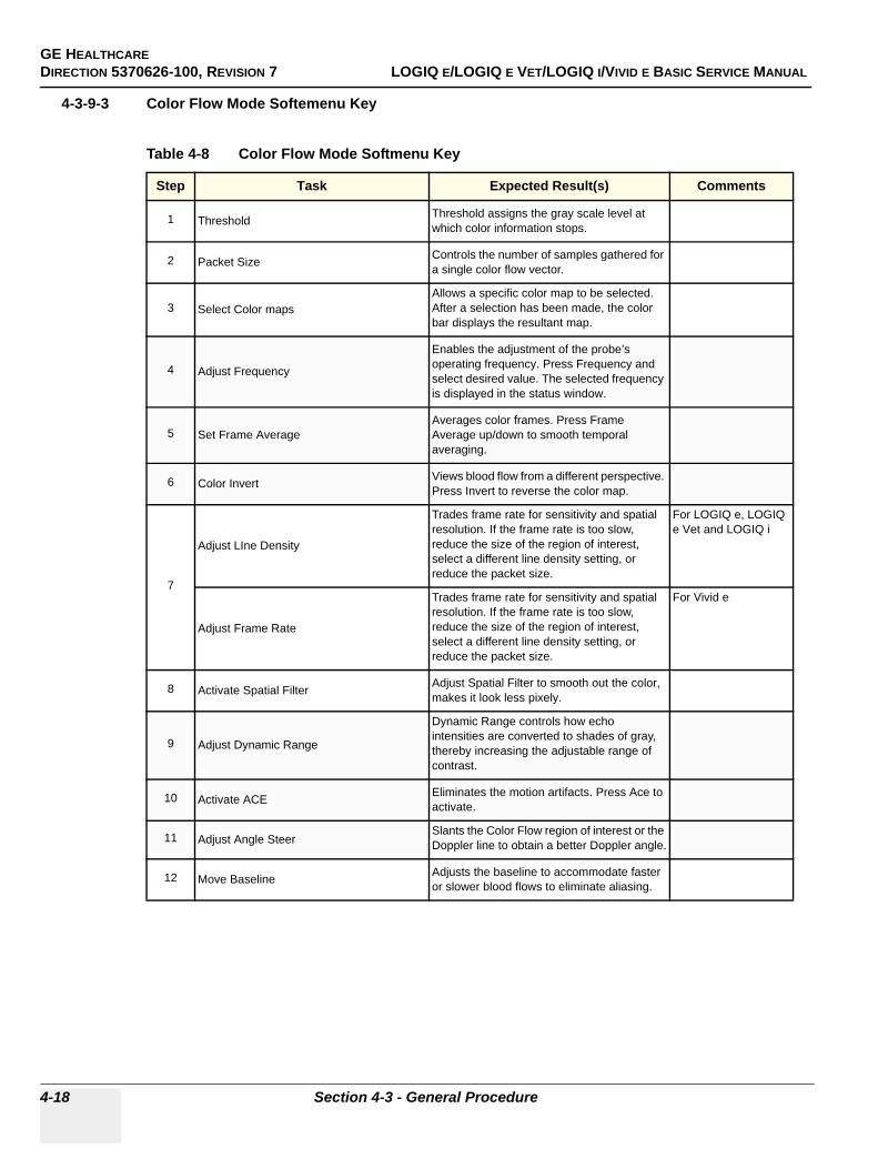
GE HEALTHCAREDIRECTION 5370626-100, REVISION 7 LOGIQ E/LOGIQ E VET/LOGIQ I/VIVID E BASIC SERVICE MANUAL
4-18 Section 4-3 - General Procedure
4-3-9-3 Color Flow Mode Softemenu Key
Table 4-8 Color Flow Mode Softmenu Key
Step Task Expected Result(s) Comments
1 Threshold Threshold assigns the gray scale level at which color information stops.
2 Packet Size Controls the number of samples gathered for a single color flow vector.
3 Select Color mapsAllows a specific color map to be selected. After a selection has been made, the color bar displays the resultant map.
4 Adjust Frequency
Enables the adjustment of the probe’s operating frequency. Press Frequency and select desired value. The selected frequency is displayed in the status window.
5 Set Frame AverageAverages color frames. Press Frame Average up/down to smooth temporal averaging.
6 Color Invert Views blood flow from a different perspective. Press Invert to reverse the color map.
7
Adjust LIne Density
Trades frame rate for sensitivity and spatial resolution. If the frame rate is too slow, reduce the size of the region of interest, select a different line density setting, or reduce the packet size.
For LOGIQ e, LOGIQ e Vet and LOGIQ i
Adjust Frame Rate
Trades frame rate for sensitivity and spatial resolution. If the frame rate is too slow, reduce the size of the region of interest, select a different line density setting, or reduce the packet size.
For Vivid e
8 Activate Spatial Filter Adjust Spatial Filter to smooth out the color, makes it look less pixely.
9 Adjust Dynamic Range
Dynamic Range controls how echo intensities are converted to shades of gray, thereby increasing the adjustable range of contrast.
10 Activate ACE Eliminates the motion artifacts. Press Ace to activate.
11 Adjust Angle SteerSlants the Color Flow region of interest or the Doppler line to obtain a better Doppler angle.
12 Move Baseline Adjusts the baseline to accommodate faster or slower blood flows to eliminate aliasing.
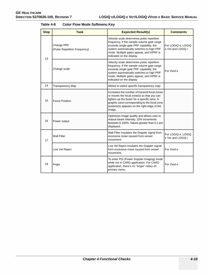
GE HEALTHCARE DIRECTION 5370626-100, REVISION 7 LOGIQ E/LOGIQ E VET/LOGIQ I/VIVID E BASIC SERVICE MANUAL
Chapter 4 Functional Checks 4-19
13
Change PRF (Pulse Repetition Frequency)
Velocity scale determines pulse repetition frequency. If the sample volume gate range exceeds single gate PRF capability, the system automatically switches to high PRF mode. Multiple gates appear, and HPRF is indicated on the display.
For LOGIQ e, LOGIQ e Vet and LOGIQ i
Change scale
Velocity scale determines pulse repetition frequency. If the sample volume gate range exceeds single gate PRF capability, the system automatically switches to high PRF mode. Multiple gates appear, and HPRF is indicated on the display.
For Vivid e
14 Transparency Map Allows to select specific transparency map
15 Focus Position
Increases the number of transmit focal zones or moves the focal zone(s) so that you can tighten up the beam for a specific area. A graphic caret corresponding to the focal zone position(s) appears on the right edge of the image.
16 Power output
Optimizes image quality and allows user to reduce beam intensity. 10% increments between 0-100%. Values greater than 0.1 are displayed.
17Wall Filter
Wall Filter insulates the Doppler signal from excessive noise caused from vessel movement.
For LOGIQ e, LOGIQ e Vet and LOGIQ i
Low Vel RejectLow Vel Reject insulates the Doppler signal from excessive noise caused from vessel movement.
For Vivid e
18 Angio
To enter PDI (Power Doppler Imaging) mode while not in CARD application. For CARD application, there’s no “Angio“ rotary on primary menu.
For Vivid e
Table 4-8 Color Flow Mode Softmenu Key
Step Task Expected Result(s) Comments
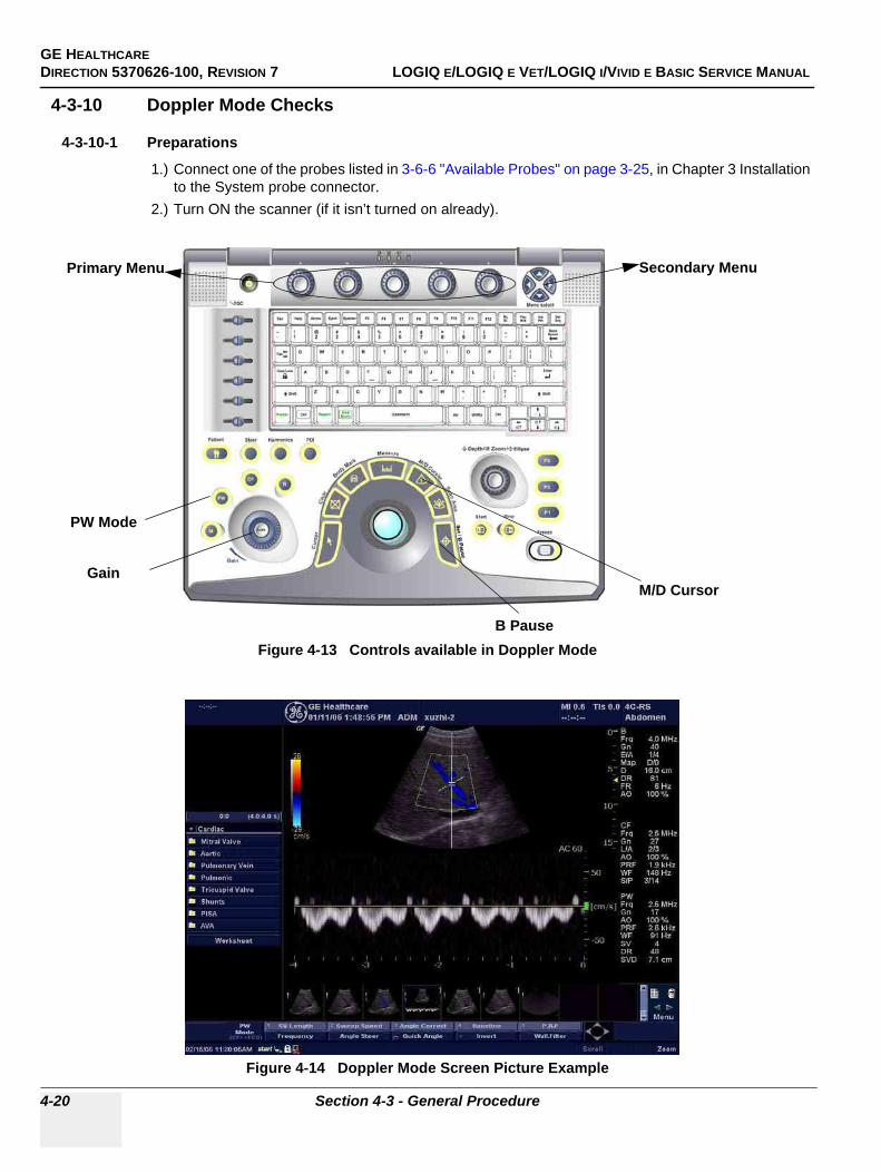
GE HEALTHCAREDIRECTION 5370626-100, REVISION 7 LOGIQ E/LOGIQ E VET/LOGIQ I/VIVID E BASIC SERVICE MANUAL
4-20 Section 4-3 - General Procedure
4-3-10 Doppler Mode Checks
4-3-10-1 Preparations
1.) Connect one of the probes listed in 3-6-6 "Available Probes" on page 3-25, in Chapter 3 Installation to the System probe connector.
2.) Turn ON the scanner (if it isn’t turned on already).
Figure 4-13 Controls available in Doppler Mode
Figure 4-14 Doppler Mode Screen Picture Example
Primary Menu Secondary Menu
M/D Cursor
PW Mode
Gain
B Pause
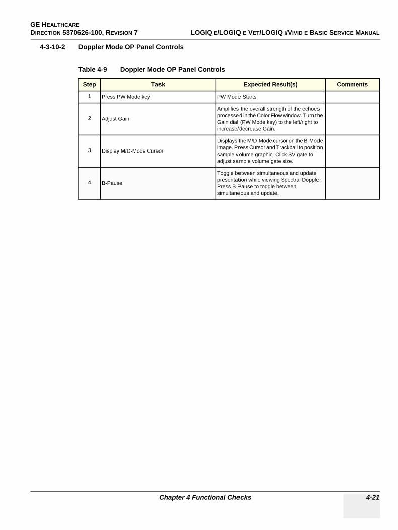
GE HEALTHCARE DIRECTION 5370626-100, REVISION 7 LOGIQ E/LOGIQ E VET/LOGIQ I/VIVID E BASIC SERVICE MANUAL
Chapter 4 Functional Checks 4-21
4-3-10-2 Doppler Mode OP Panel Controls
Table 4-9 Doppler Mode OP Panel Controls
Step Task Expected Result(s) Comments
1 Press PW Mode key PW Mode Starts
2 Adjust Gain
Amplifies the overall strength of the echoes processed in the Color Flow window. Turn the Gain dial (PW Mode key) to the left/right to increase/decrease Gain.
3 Display M/D-Mode Cursor
Displays the M/D-Mode cursor on the B-Mode image. Press Cursor and Trackball to position sample volume graphic. Click SV gate to adjust sample volume gate size.
4 B-Pause
Toggle between simultaneous and update presentation while viewing Spectral Doppler. Press B Pause to toggle between simultaneous and update.
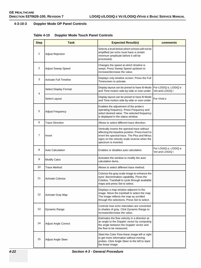
GE HEALTHCAREDIRECTION 5370626-100, REVISION 7 LOGIQ E/LOGIQ E VET/LOGIQ I/VIVID E BASIC SERVICE MANUAL
4-22 Section 4-3 - General Procedure
4-3-10-3 Doppler Mode OP Panel Controls
Table 4-10 Doppler Mode Touch Panel Controls
Step Task Expected Result(s) comments
1 Adjust Rejection
Selects a level below which echoes will not be amplified (an echo must have a certain minimum amplitude before it will be processed).
2 Adjust Sweep SpeedChanges the speed at which timeline is swept. Press Sweep Speed up/down to increase/decrease the value.
3 Activate Full Timeline Displays only timeline screen. Press the Full Timescreen to activate.
4Select Display Format Display layout can be preset to have B-Mode
and Time-motion side-by-side or over-under.For LOGIQ e, LOGIQ e Vet and LOGIQ i
Select Layout Display layout can be preset to have B-Mode and Time-motion side-by-side or over-under. For Vivid e
5 Adjust Frequency
Enables the adjustment of the probe’s operating frequency. Press Frequency and select desired value. The selected frequency is displayed in the status window.
6 Trace Direction Allows to select different trace direction.
7 Invert
Vertically inverts the spectral trace without affecting the baseline position. Press invert to invert the spectral trace. The Plus and Minus signs on the velocity scale reverse when the spectrum is inverted.
8 Auto Calculation Enables or disables auto calculation. For LOGIQ e, LOGIQ e Vet and LOGIQ i
9 Modify Calcs Activates the window to modify the auto calculation items.
10 Trace Method Allows to select different trace method.
11 Activate Colorize
Colorize the gray scale image to enhance the eyes’ discrimination capability. Press the Cololize, Trackball to cycle through available maps and press Set to select.
12 Activate Gray Map
Displays a map window adjacent to the image. Move the trackball to select the map. The image reflects the map as scrolled through the selections. Press Set to select.
13 Dynamic RangeControls how echo intensities are converted to shades of gray. Click Dynamic Range to increase/decrease the value.
14 Adjust Angle Correct
Estimates the flow velocity in a direction at an angle to the Doppler vector by computing the angle between the Doppler vector and the flow to be measured.
15 Adjust Angle Steer
Slant the Color Flow linear image left or right to get more information without moving probes. Click Angle Steer to the left to slant the linear image.
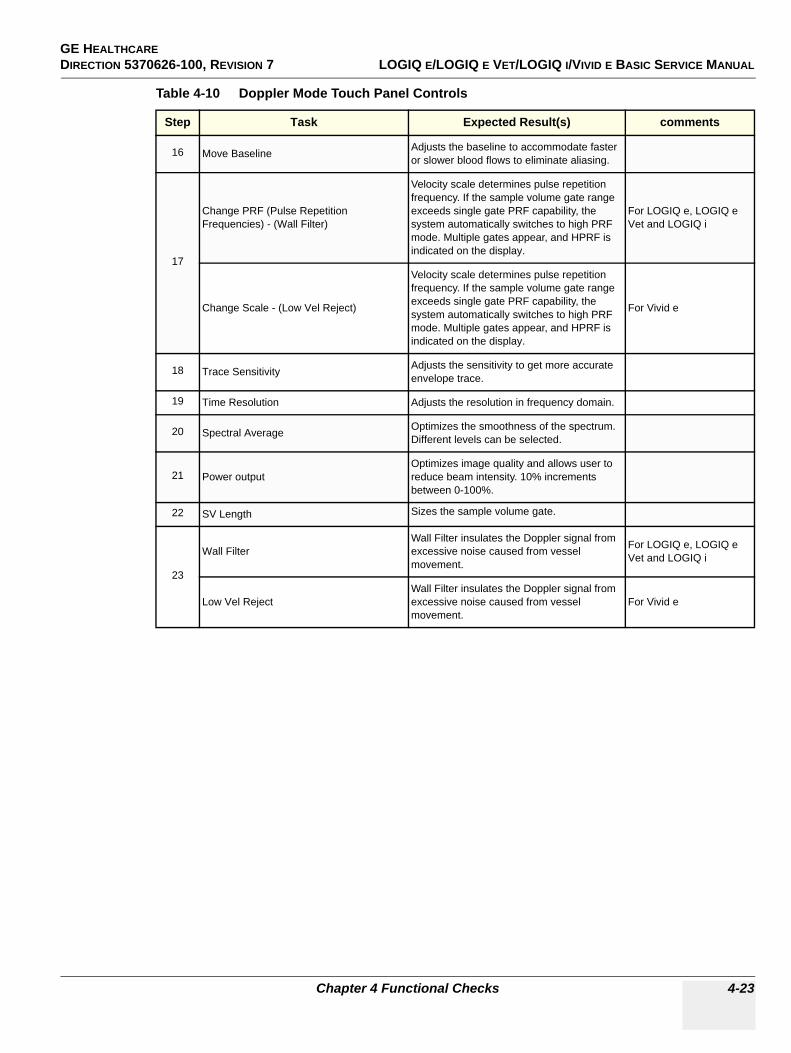
GE HEALTHCARE DIRECTION 5370626-100, REVISION 7 LOGIQ E/LOGIQ E VET/LOGIQ I/VIVID E BASIC SERVICE MANUAL
Chapter 4 Functional Checks 4-23
16 Move Baseline Adjusts the baseline to accommodate faster or slower blood flows to eliminate aliasing.
17
Change PRF (Pulse Repetition Frequencies) - (Wall Filter)
Velocity scale determines pulse repetition frequency. If the sample volume gate range exceeds single gate PRF capability, the system automatically switches to high PRF mode. Multiple gates appear, and HPRF is indicated on the display.
For LOGIQ e, LOGIQ e Vet and LOGIQ i
Change Scale - (Low Vel Reject)
Velocity scale determines pulse repetition frequency. If the sample volume gate range exceeds single gate PRF capability, the system automatically switches to high PRF mode. Multiple gates appear, and HPRF is indicated on the display.
For Vivid e
18 Trace Sensitivity Adjusts the sensitivity to get more accurate envelope trace.
19 Time Resolution Adjusts the resolution in frequency domain.
20 Spectral Average Optimizes the smoothness of the spectrum. Different levels can be selected.
21 Power outputOptimizes image quality and allows user to reduce beam intensity. 10% increments between 0-100%.
22 SV Length Sizes the sample volume gate.
23
Wall FilterWall Filter insulates the Doppler signal from excessive noise caused from vessel movement.
For LOGIQ e, LOGIQ e Vet and LOGIQ i
Low Vel RejectWall Filter insulates the Doppler signal from excessive noise caused from vessel movement.
For Vivid e
Table 4-10 Doppler Mode Touch Panel Controls
Step Task Expected Result(s) comments
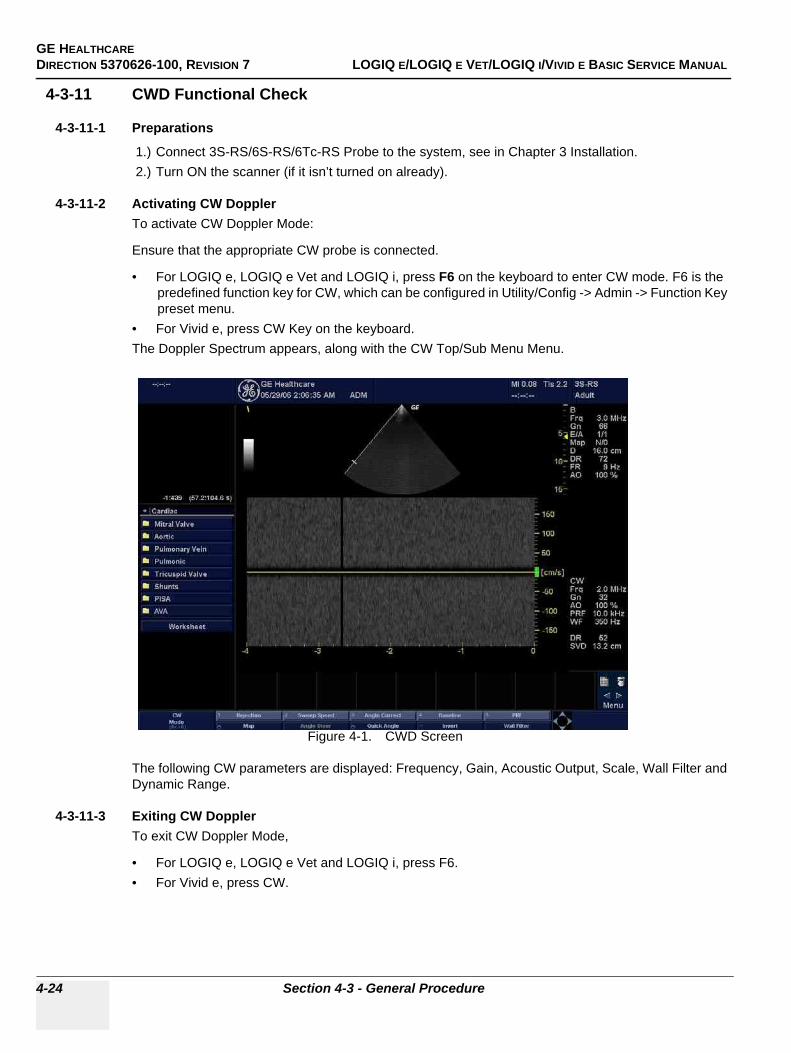
GE HEALTHCAREDIRECTION 5370626-100, REVISION 7 LOGIQ E/LOGIQ E VET/LOGIQ I/VIVID E BASIC SERVICE MANUAL
4-24 Section 4-3 - General Procedure
4-3-11 CWD Functional Check
4-3-11-1 Preparations
1.) Connect 3S-RS/6S-RS/6Tc-RS Probe to the system, see in Chapter 3 Installation.2.) Turn ON the scanner (if it isn’t turned on already).
4-3-11-2 Activating CW DopplerTo activate CW Doppler Mode:
Ensure that the appropriate CW probe is connected.
• For LOGIQ e, LOGIQ e Vet and LOGIQ i, press F6 on the keyboard to enter CW mode. F6 is the predefined function key for CW, which can be configured in Utility/Config -> Admin -> Function Key preset menu.
• For Vivid e, press CW Key on the keyboard.The Doppler Spectrum appears, along with the CW Top/Sub Menu Menu.
Figure 4-1. CWD Screen
The following CW parameters are displayed: Frequency, Gain, Acoustic Output, Scale, Wall Filter and Dynamic Range.
4-3-11-3 Exiting CW DopplerTo exit CW Doppler Mode,
• For LOGIQ e, LOGIQ e Vet and LOGIQ i, press F6. • For Vivid e, press CW.
GE HEALTHCARE DIRECTION 5370626-100, REVISION 7 LOGIQ E/LOGIQ E VET/LOGIQ I/VIVID E BASIC SERVICE MANUAL
Chapter 4 Functional Checks 4-25
4-3-12 Basic Measurements
NOTE: The following instructions assume that you first scan the patient and then press Freeze.
4-3-12-1 Distance and Tissue Depth Measurements
1.) Press MEASURE once; an active caliper displays.2.) To position the active caliper at the start point (distance) or the most anterior point (tissue
depth), move the TRACKBALL.3.) To fix the start point, press Set. The system fixes the first caliper and displays a second active
caliper.4.) To position the second active caliper at the end point (distance) or the most posterior point
(tissue depth), move the TRACKBALL.5.) To complete the measurement, press SET. The system displays the distance or tissue depth
value in the measurement results window.
4-3-12-2 Circumference/Area (Ellipse) Measurement
1.) Press MEASURE once; an active caliper displays.2.) To position the active caliper, move the TRACKBALL.3.) To fix the start point, press SET. The system fixes the first caliper and displays a second active
caliper.4.) To position the second caliper, move the TRACKBALL.5.) Adjust the ELLIPSE; an ellipse with an initial circle shape appears.6.) To position the ellipse and to size the measured axes (move the calipers), move the
TRACKBALL.7.) To increase the size, rotate the ELLIPSE button clockwise. To decrease the size, contrarotate
the ELLIPSE button.8.) To complete the measurement, press SET. The system displays the circumference and area
in the measurement results window.
4-3-12-3 WorksheetsMeasurement/Calculation worksheets are available to display and edit measurements and calculations. There are generic worksheets as well as Application specific worksheets. The worksheets are selected from the Measurement Touch Panel.
4-3-13 Probe/Connectors Usage
4-3-13-1 Connecting a probe
1.) Place the probe's carrying case on a stable surface and open the case.2.) Carefully remove the probe and unwrap the probe cable.3.) DO NOT allow the probe head to hang free. Impact to the probe head could result in irreparable
damage.4.) Align the connector with the probe port and carefully push into place.5.) Lock the probe latch upward.6.) Carefully position the probe cord so it is free to move and is not resting on the floor.
4-3-13-2 Activating the probeThe probe activates in the currently-selected operating mode. The probe's default settings for the mode and selected exam are used automatically.
GE HEALTHCAREDIRECTION 5370626-100, REVISION 7 LOGIQ E/LOGIQ E VET/LOGIQ I/VIVID E BASIC SERVICE MANUAL
4-26 Section 4-3 - General Procedure
4-3-13-3 Deactivating the probe
1.) Press the Freeze key.2.) Gently wipe the excess gel from the face of the probe. (Refer to the Basic User Manual for
complete probe cleaning instructions.)3.) Carefully slide the probe around the right side of the keyboard, toward the probe holder.
Ensure that the probe is placed gently in the probe holder.
4-3-13-4 Disconnecting the probeProbes can be disconnected at any time. However, the probe should not be selected as the active probe.
1.) Unlock the probe latch downward.2.) Pull the probe and connector straight out of the probe port.3.) Carefully slide the probe and connector away from the probe port and around the right side of the
keyboard.4.) Ensure the cable is free.
5.) Be sure that the probe head is clean before placing the probe in its storage box.
4-3-14 Using Cine
4-3-14-1 Activating CINEPress Freeze, then roll the Trackball to activate CINE. To start CINE Loop playback, press Run/Stop. To stop CINE Loop playback. press Run/Stop.
4-3-14-2 Quickly Move to Start/End FramePress First to move to the first CINE frame; press Last to move to the last CINE frame.
4-3-14-3 Start Frame/End FramePress the Start Frame Two-Button Softkey to move to the beginning of the CINE Loop. Adjust the Start Frame up/down Two-Button Softkey upward to move forward through the CINE Loop. Adjust the Softkey downward to move backward through the CINE Loop.
Press the End Frame Two-Button Softkey to move to the end of the CINE Loop. Adjust the End Frame up/down Two-Button Softkey upward to move forward through the CINE Loop. Adjust the Softkey downward to move backward through the CINE Loop.
4-3-14-4 Adjusting the CINE Loop Playback SpeedAdjust the Loop Speed up/down Two-Button Softkey to increase/decrease the CINE Loop playback speed.
4-3-14-5 Moving through a CINE Loop Frame By FrameAdjust the Frame by Frame up/down Two-Button Softkey to move through CINE memory one frame at a time.
WARNINGWARNING Take the following precautions with the probe cables: Do not bend. If you have purchased the cart option, be sure to keep probe cables free from the wheels.
WARNINGWARNING Be careful not to trip on the probe cables if using the device without the optional cart.
GE HEALTHCARE DIRECTION 5370626-100, REVISION 7 LOGIQ E/LOGIQ E VET/LOGIQ I/VIVID E BASIC SERVICE MANUAL
Chapter 4 Functional Checks 4-27
4-3-15 Image Management (QG)For Image Management functionality refer to the LOGIQ e/LOGIQ e Vet/LOGIQ i/Vivid e Quick Guide. It talks about several topics:
• Clipboard• Printing Images• Browsing and Managing an Exam’s Stored Image• Connectivity, and Dataflow Concept and Creation• Starting an Exam• Configuring Connectivity• TCP/IP• Services (Destinations)• Buttons• Views• Verifying and Pinging a Device
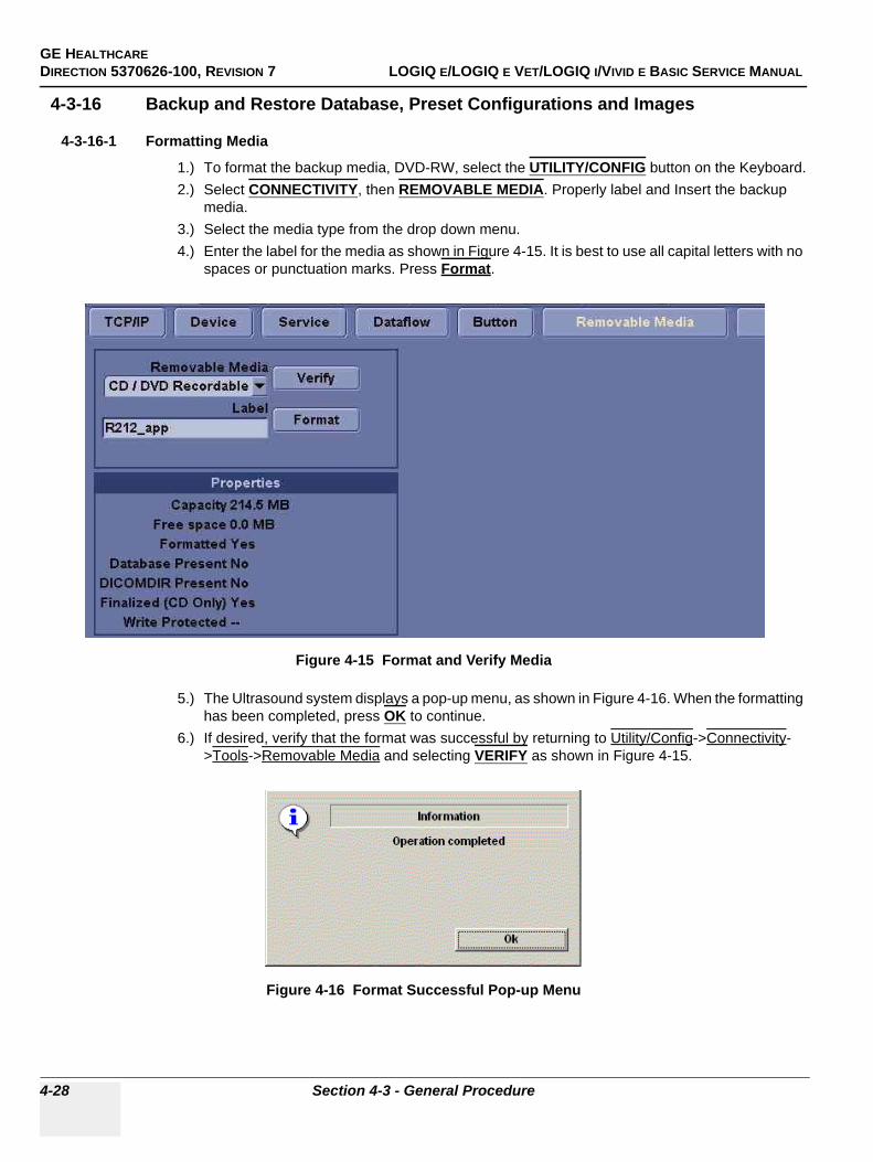
GE HEALTHCAREDIRECTION 5370626-100, REVISION 7 LOGIQ E/LOGIQ E VET/LOGIQ I/VIVID E BASIC SERVICE MANUAL
4-28 Section 4-3 - General Procedure
4-3-16 Backup and Restore Database, Preset Configurations and Images
4-3-16-1 Formatting Media
1.) To format the backup media, DVD-RW, select the UTILITY/CONFIG button on the Keyboard.2.) Select CONNECTIVITY, then REMOVABLE MEDIA. Properly label and Insert the backup
media. 3.) Select the media type from the drop down menu.4.) Enter the label for the media as shown in Figure 4-15. It is best to use all capital letters with no
spaces or punctuation marks. Press Format.
5.) The Ultrasound system displays a pop-up menu, as shown in Figure 4-16. When the formatting has been completed, press OK to continue.
6.) If desired, verify that the format was successful by returning to Utility/Config->Connectivity->Tools->Removable Media and selecting VERIFY as shown in Figure 4-15.
Figure 4-15 Format and Verify Media
Figure 4-16 Format Successful Pop-up Menu
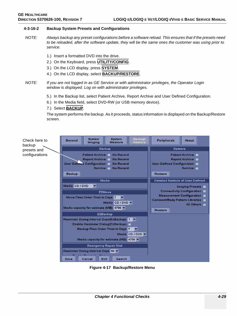
GE HEALTHCARE DIRECTION 5370626-100, REVISION 7 LOGIQ E/LOGIQ E VET/LOGIQ I/VIVID E BASIC SERVICE MANUAL
Chapter 4 Functional Checks 4-29
4-3-16-2 Backup System Presets and Configurations
NOTE: Always backup any preset configurations before a software reload. This ensures that if the presets need to be reloaded, after the software update, they will be the same ones the customer was using prior to service.
1.) Insert a formatted DVD into the drive.2.) On the Keyboard, press UTILITY/CONFIG.3.) On the LCD display, press SYSTEM.4.) On the LCD display, select BACKUP/RESTORE.
NOTE: If you are not logged in as GE Service or with administrator privileges, the Operator Login window is displayed. Log on with administrator privileges.
5.) In the Backup list, select Patient Archive, Report Archive and User Defined Configuration.6.) In the Media field, select DVD-RW (or USB memory device).7.) Select BACKUP.The system performs the backup. As it proceeds, status information is displayed on the Backup/Restore screen.
Figure 4-17 Backup/Restore Menu
Check here to backup presets and configurations
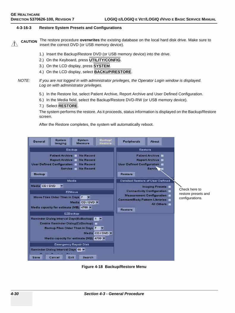
GE HEALTHCAREDIRECTION 5370626-100, REVISION 7 LOGIQ E/LOGIQ E VET/LOGIQ I/VIVID E BASIC SERVICE MANUAL
4-30 Section 4-3 - General Procedure
4-3-16-3 Restore System Presets and Configurations
1.) Insert the Backup/Restore DVD (or USB memory device) into the drive. 2.) On the Keyboard, press UTILITY/CONFIG.3.) On the LCD display, press SYSTEM.4.) On the LCD display, select BACKUP/RESTORE.
NOTE: If you are not logged in with administrator privileges, the Operator Login window is displayed. Log on with administrator privileges.
5.) In the Restore list, select Patient Archive, Report Archive and User Defined Configuration.6.) In the Media field, select the Backup/Restore DVD-RW (or USB memory device).7.) Select RESTORE.The system performs the restore. As it proceeds, status information is displayed on the Backup/Restore screen.
After the Restore completes, the system will automatically reboot.
CAUTION The restore procedure overwrites the existing database on the local hard disk drive. Make sure to insert the correct DVD (or USB memory device).
Figure 4-18 Backup/Restore Menu
Check here to restore presets and configurations.
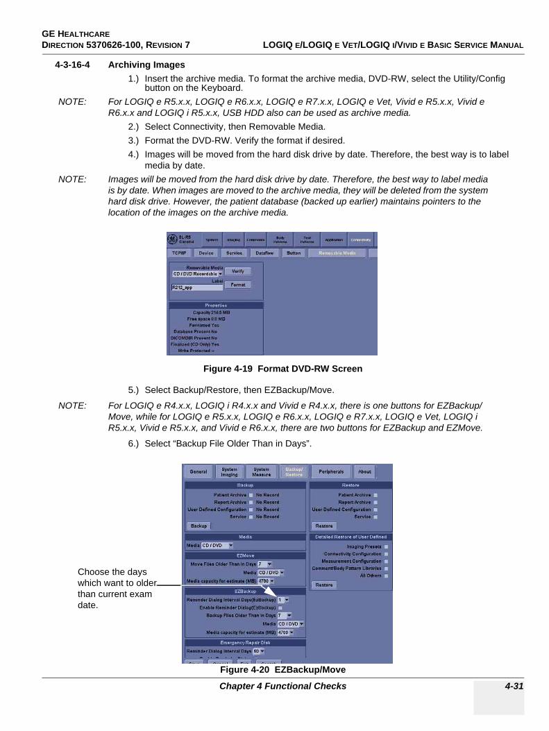
GE HEALTHCARE DIRECTION 5370626-100, REVISION 7 LOGIQ E/LOGIQ E VET/LOGIQ I/VIVID E BASIC SERVICE MANUAL
Chapter 4 Functional Checks 4-31
4-3-16-4 Archiving Images1.) Insert the archive media. To format the archive media, DVD-RW, select the Utility/Config
button on the Keyboard. NOTE: For LOGIQ e R5.x.x, LOGIQ e R6.x.x, LOGIQ e R7.x.x, LOGIQ e Vet, Vivid e R5.x.x, Vivid e
R6.x.x and LOGIQ i R5.x.x, USB HDD also can be used as archive media.2.) Select Connectivity, then Removable Media. 3.) Format the DVD-RW. Verify the format if desired.4.) Images will be moved from the hard disk drive by date. Therefore, the best way is to label
media by date. NOTE: Images will be moved from the hard disk drive by date. Therefore, the best way to label media
is by date. When images are moved to the archive media, they will be deleted from the system hard disk drive. However, the patient database (backed up earlier) maintains pointers to the location of the images on the archive media.
5.) Select Backup/Restore, then EZBackup/Move.
NOTE: For LOGIQ e R4.x.x, LOGIQ i R4.x.x and Vivid e R4.x.x, there is one buttons for EZBackup/Move, while for LOGIQ e R5.x.x, LOGIQ e R6.x.x, LOGIQ e R7.x.x, LOGIQ e Vet, LOGIQ i R5.x.x, Vivid e R5.x.x, and Vivid e R6.x.x, there are two buttons for EZBackup and EZMove.
6.) Select “Backup File Older Than in Days”.
Figure 4-19 Format DVD-RW Screen
Figure 4-20 EZBackup/Move
Choose the days which want to older than current exam date.
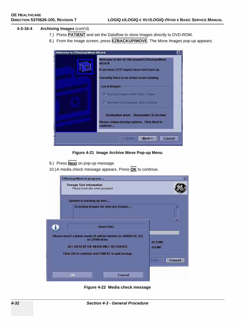
GE HEALTHCAREDIRECTION 5370626-100, REVISION 7 LOGIQ E/LOGIQ E VET/LOGIQ I/VIVID E BASIC SERVICE MANUAL
4-32 Section 4-3 - General Procedure
4-3-16-4 Archiving Images (cont’d)7.) Press PATIENT and set the Dataflow to store images directly to DVD-ROM.8.) From the image screen, press EZBACKUP/MOVE. The Move Images pop-up appears.
9.) Press Next on pop-up message.10.)A media check message appears. Press OK to continue.
Figure 4-21 Image Archive Move Pop-up Menu
Figure 4-22 Media check message
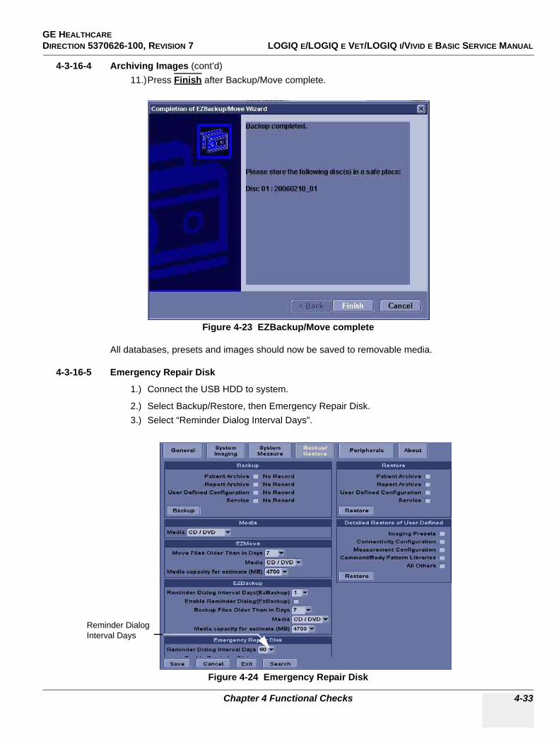
GE HEALTHCARE DIRECTION 5370626-100, REVISION 7 LOGIQ E/LOGIQ E VET/LOGIQ I/VIVID E BASIC SERVICE MANUAL
Chapter 4 Functional Checks 4-33
4-3-16-4 Archiving Images (cont’d)11.)Press Finish after Backup/Move complete.
All databases, presets and images should now be saved to removable media.
4-3-16-5 Emergency Repair Disk
1.) Connect the USB HDD to system.
2.) Select Backup/Restore, then Emergency Repair Disk.3.) Select “Reminder Dialog Interval Days”.
Figure 4-23 EZBackup/Move complete
Figure 4-24 Emergency Repair Disk
Reminder Dialog Interval Days

GE HEALTHCAREDIRECTION 5370626-100, REVISION 7 LOGIQ E/LOGIQ E VET/LOGIQ I/VIVID E BASIC SERVICE MANUAL
4-34 Section 4-3 - General Procedure
4-3-16-5 Emergency Repair Disk (cont’d)4.) Return to scan mode. Press Ctrl + B, the Emergency Disk Making window pop-up appears.
5.) Press Next on pop-up message.6.) A storage information message appears. Press Next to continue.
Figure 4-25 Emergency Disk Making Pop-up Menu
Figure 4-26 Storage Information message
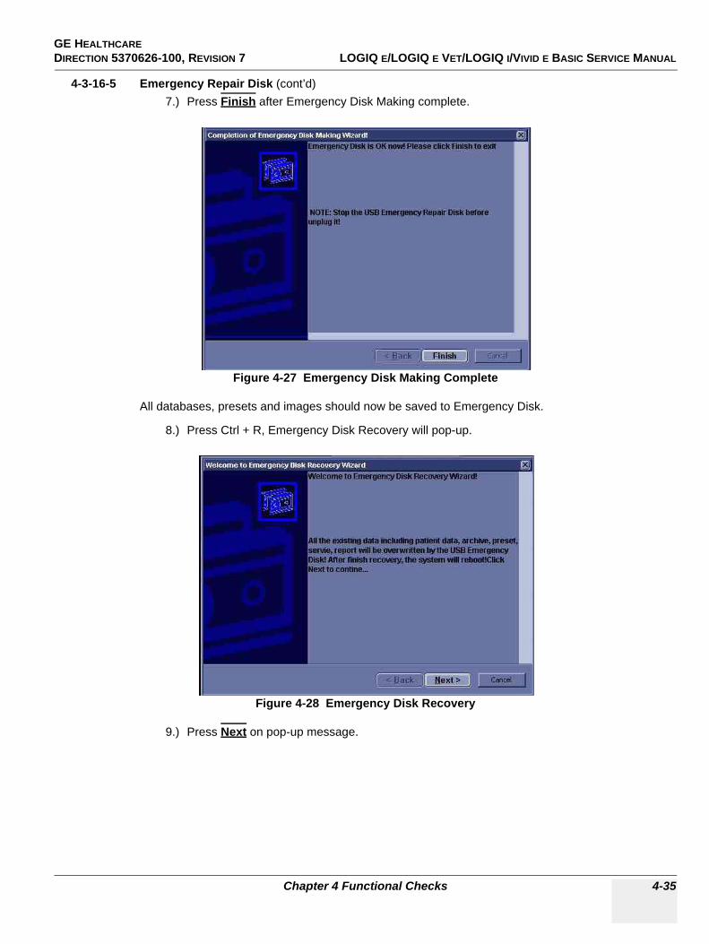
GE HEALTHCARE DIRECTION 5370626-100, REVISION 7 LOGIQ E/LOGIQ E VET/LOGIQ I/VIVID E BASIC SERVICE MANUAL
Chapter 4 Functional Checks 4-35
4-3-16-5 Emergency Repair Disk (cont’d)7.) Press Finish after Emergency Disk Making complete.
All databases, presets and images should now be saved to Emergency Disk.
8.) Press Ctrl + R, Emergency Disk Recovery will pop-up.
9.) Press Next on pop-up message.
Figure 4-27 Emergency Disk Making Complete
Figure 4-28 Emergency Disk Recovery
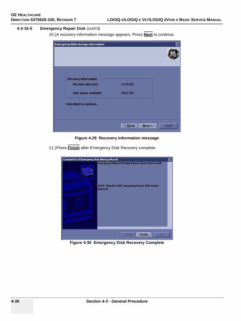
GE HEALTHCAREDIRECTION 5370626-100, REVISION 7 LOGIQ E/LOGIQ E VET/LOGIQ I/VIVID E BASIC SERVICE MANUAL
4-36 Section 4-3 - General Procedure
4-3-16-5 Emergency Repair Disk (cont’d)10.)A recovery information message appears. Press Next to continue.
11.)Press Finish after Emergency Disk Recovery complete.
Figure 4-29 Recovery Information message
Figure 4-30 Emergency Disk Recovery Complete
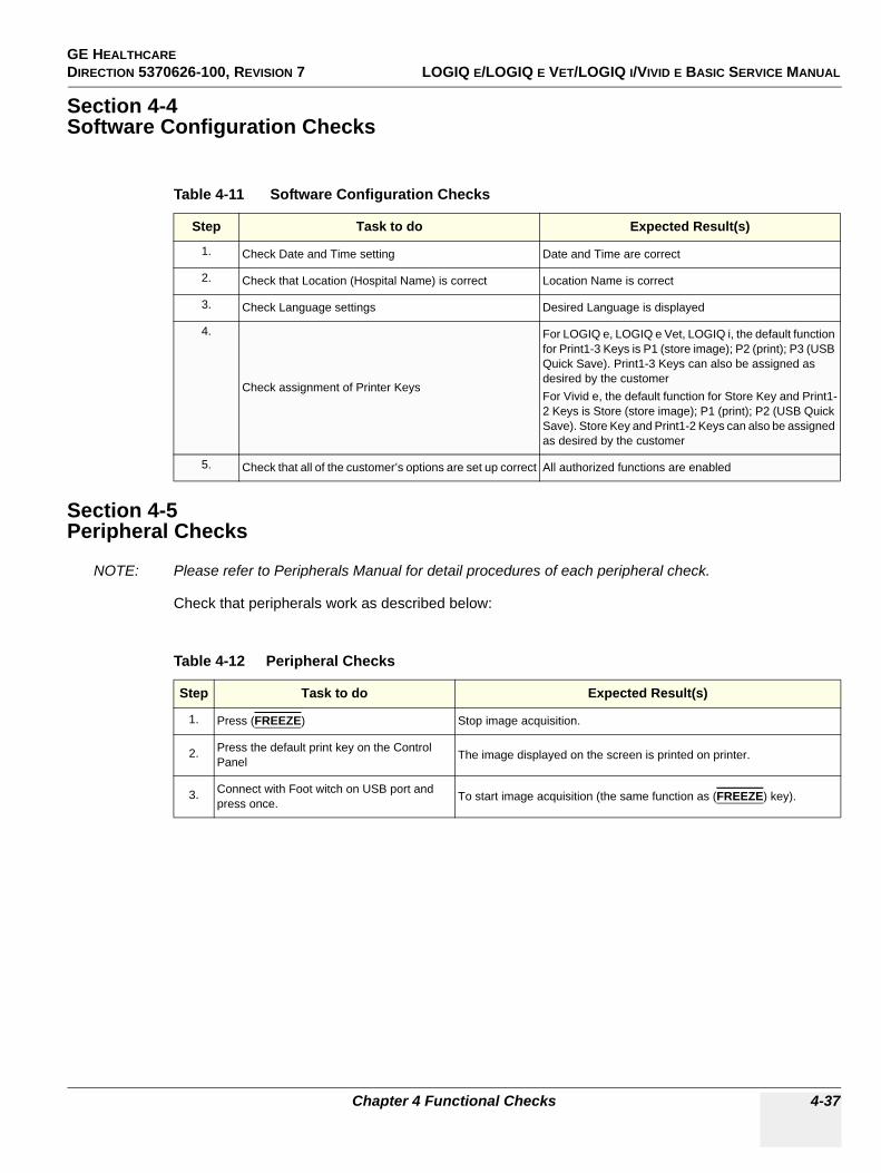
GE HEALTHCARE DIRECTION 5370626-100, REVISION 7 LOGIQ E/LOGIQ E VET/LOGIQ I/VIVID E BASIC SERVICE MANUAL
Chapter 4 Functional Checks 4-37
Section 4-4Software Configuration Checks
Section 4-5Peripheral Checks
NOTE: Please refer to Peripherals Manual for detail procedures of each peripheral check.
Check that peripherals work as described below:
Table 4-11 Software Configuration Checks
Step Task to do Expected Result(s)
1. Check Date and Time setting Date and Time are correct
2. Check that Location (Hospital Name) is correct Location Name is correct
3. Check Language settings Desired Language is displayed
4.
Check assignment of Printer Keys
For LOGIQ e, LOGIQ e Vet, LOGIQ i, the default function for Print1-3 Keys is P1 (store image); P2 (print); P3 (USB Quick Save). Print1-3 Keys can also be assigned as desired by the customerFor Vivid e, the default function for Store Key and Print1-2 Keys is Store (store image); P1 (print); P2 (USB Quick Save). Store Key and Print1-2 Keys can also be assigned as desired by the customer
5. Check that all of the customer’s options are set up correct All authorized functions are enabled
Table 4-12 Peripheral Checks
Step Task to do Expected Result(s)
1. Press (FREEZE) Stop image acquisition.
2. Press the default print key on the Control Panel The image displayed on the screen is printed on printer.
3. Connect with Foot witch on USB port and press once. To start image acquisition (the same function as (FREEZE) key).

GE HEALTHCAREDIRECTION 5370626-100, REVISION 7 LOGIQ E/LOGIQ E VET/LOGIQ I/VIVID E BASIC SERVICE MANUAL
4-38 Section 4-5 - Peripheral Checks
This page was intentionally left blank.
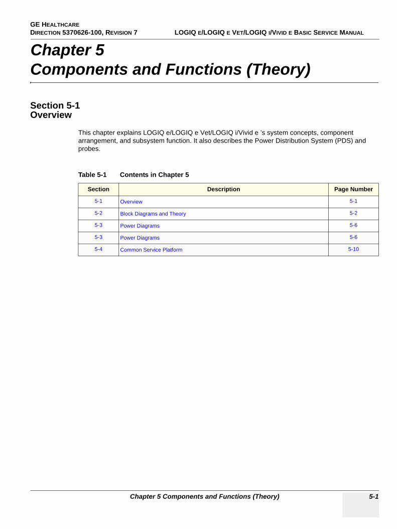
GE HEALTHCAREDIRECTION 5370626-100, REVISION 7 LOGIQ E/LOGIQ E VET/LOGIQ I/VIVID E BASIC SERVICE MANUAL
Chapter 5 Components and Functions (Theory) 5-1
Chapter 5Components and Functions (Theory)
Section 5-1Overview
This chapter explains LOGIQ e/LOGIQ e Vet/LOGIQ i/Vivid e ’s system concepts, component arrangement, and subsystem function. It also describes the Power Distribution System (PDS) and probes.
Table 5-1 Contents in Chapter 5
Section Description Page Number
5-1 Overview 5-1
5-2 Block Diagrams and Theory 5-2
5-3 Power Diagrams 5-6
5-3 Power Diagrams 5-6
5-4 Common Service Platform 5-10
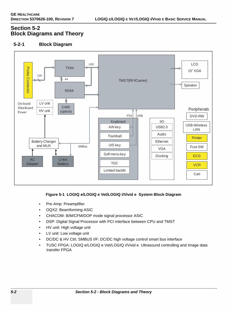
GE HEALTHCAREDIRECTION 5370626-100, REVISION 7 LOGIQ E/LOGIQ E VET/LOGIQ I/VIVID E BASIC SERVICE MANUAL
5-2 Section 5-2 - Block Diagrams and Theory
Section 5-2Block Diagrams and Theory
5-2-1 Block Diagram
• Pre Amp: Preamplifier• OQX2: Beamforming ASIC• CHACOM: B/M/CFM/DOP mode signal processor ASIC• DSP: Digital Signal Processor with PCI interface between CPU and TMST• HV unit: High voltage unit• LV unit: Low voltage unit• DC/DC & HV Ctrl, SMBUS I/F: DC/DC high voltage control smart bus interface• TUSC FPGA: LOGIQ e/LOGIQ e Vet/LOGIQ i/Vivid e Ultrasound controlling and Image data
transfer FPGA
Figure 5-1 LOGIQ e/LOGIQ e Vet/LOGIQ i/Vivid e System Block Diagram
Probe
Connector
TX64
RX64
TMST(RFI/Carrier)
HV unit
Battery Chargerand MUX
ACAdapter
Li-IonBattery
KeyboardA/N key
Trackball
U/S key
TGC
Soft menu key
LCD
15” XGA
I/O
Peripherals
USB2.0
Ethernet
VGA
Docking
Audio
Speaker
DVD-RW
USB-WirelessLAN
Printer
Limited backlit
ECG
Foot SW
VCR
Cart
SMBus
PS2 USB
64128
CWD(option)
USC
LV unitOn boardDistributedPower
GE HEALTHCAREDIRECTION 5370626-100, REVISION 7 LOGIQ E/LOGIQ E VET/LOGIQ I/VIVID E BASIC SERVICE MANUAL
Chapter 5 Components and Functions (Theory) 5-3
5-2-2 General Information• LOGIQ e/LOGIQ e Vet/LOGIQ i/Vivid e is an ultrasound imaging scanner.• The system can be used for:
- 2D Black and White imaging - 2D Color Flow - M-Mode Black and White imaging - Doppler- A number of combinations of the above
• LOGIQ e/LOGIQ e Vet/LOGIQ i/Vivid e is a digital beam forming system that can handle up to 128 elements linear probes.
• Signal flow from the Probe Connector Panel to the Front End, to the Mid Processors and Back End Processor and finally to the LCD and peripherals.
• System configuration is stored on a hard disk drive and all necessary software is loaded from the hard disk drive on power up.
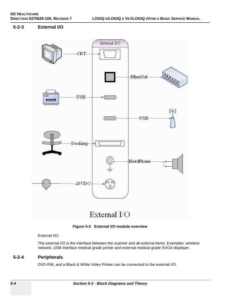
GE HEALTHCAREDIRECTION 5370626-100, REVISION 7 LOGIQ E/LOGIQ E VET/LOGIQ I/VIVID E BASIC SERVICE MANUAL
5-4 Section 5-2 - Block Diagrams and Theory
5-2-3 External I/O
External I/O:
The external I/O is the interface between the scanner and all external items. Examples: wireless network, USB interface medical grade printer and external medical grade SVGA displayer.
5-2-4 PeripheralsDVD-RW, and a Black & White Video Printer can be connected to the external I/O.
Figure 5-2 External I/O module overview
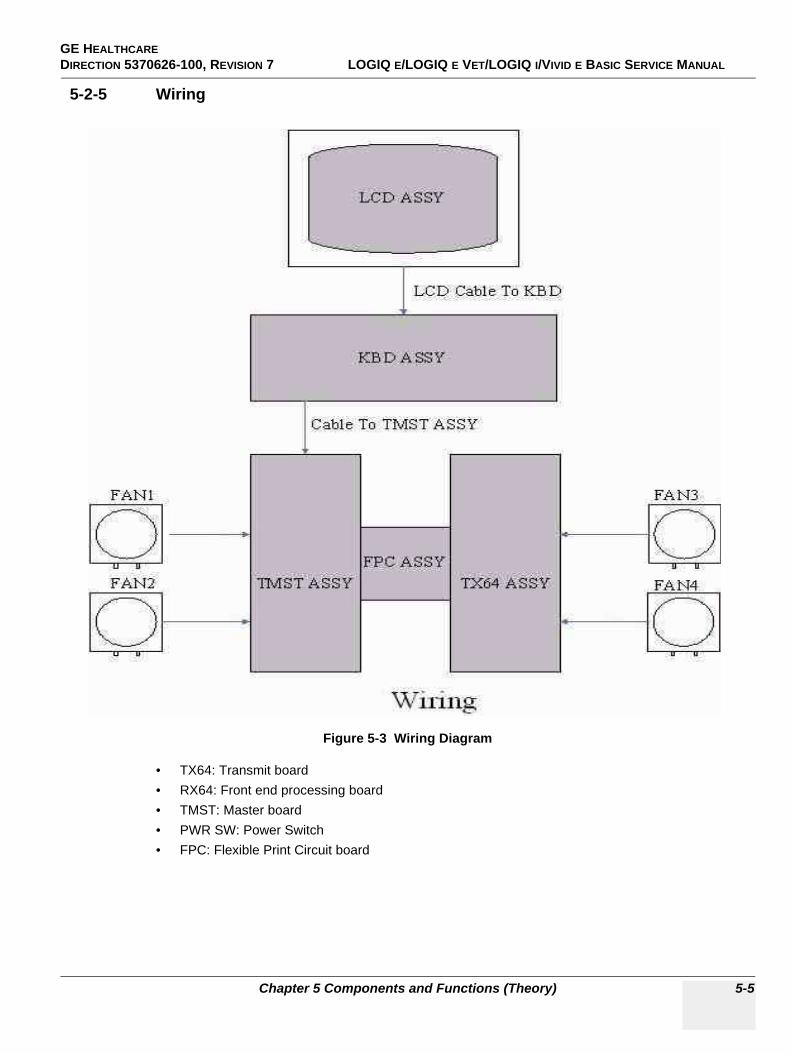
GE HEALTHCAREDIRECTION 5370626-100, REVISION 7 LOGIQ E/LOGIQ E VET/LOGIQ I/VIVID E BASIC SERVICE MANUAL
Chapter 5 Components and Functions (Theory) 5-5
5-2-5 Wiring
• TX64: Transmit board• RX64: Front end processing board• TMST: Master board• PWR SW: Power Switch• FPC: Flexible Print Circuit board
Figure 5-3 Wiring Diagram
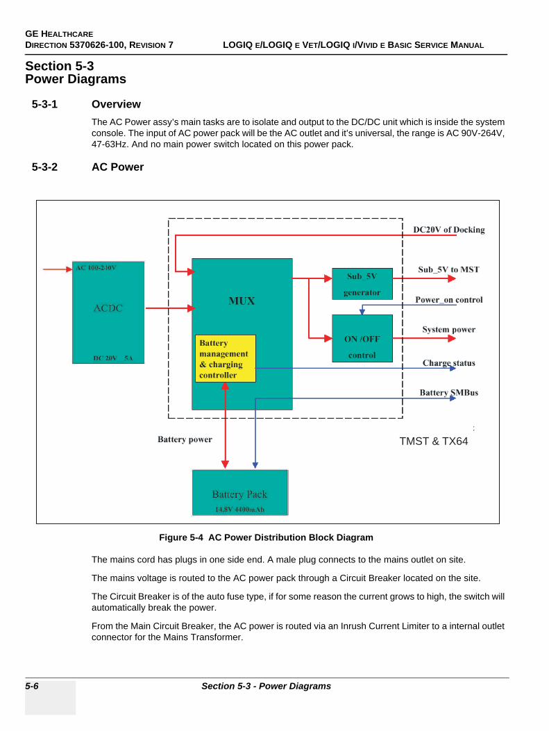
GE HEALTHCAREDIRECTION 5370626-100, REVISION 7 LOGIQ E/LOGIQ E VET/LOGIQ I/VIVID E BASIC SERVICE MANUAL
5-6 Section 5-3 - Power Diagrams
Section 5-3Power Diagrams
5-3-1 OverviewThe AC Power assy’s main tasks are to isolate and output to the DC/DC unit which is inside the system console. The input of AC power pack will be the AC outlet and it’s universal, the range is AC 90V-264V, 47-63Hz. And no main power switch located on this power pack.
5-3-2 AC Power
The mains cord has plugs in one side end. A male plug connects to the mains outlet on site.
The mains voltage is routed to the AC power pack through a Circuit Breaker located on the site.
The Circuit Breaker is of the auto fuse type, if for some reason the current grows to high, the switch will automatically break the power.
From the Main Circuit Breaker, the AC power is routed via an Inrush Current Limiter to a internal outlet connector for the Mains Transformer.
Figure 5-4 AC Power Distribution Block Diagram
TMST & TX64
GE HEALTHCAREDIRECTION 5370626-100, REVISION 7 LOGIQ E/LOGIQ E VET/LOGIQ I/VIVID E BASIC SERVICE MANUAL
Chapter 5 Components and Functions (Theory) 5-7
5-3-3 Battery chargingThe charging circuit is lithium-Ion battery charge and discharge controller. This block can switch the power between the battery and the output of AC Pack. If the output of AC Pack is available, the power input of Charge Board Unit should be from the AC Pack and the battery will be charged if it’s not full. This block will be also in charge of the battery charging monitor to avoid the battery over heat and over charging, charging will be shut off automatically if battery is charged fully. The battery will discharge to provide the power to the system when out of AC power pack output or AC line.
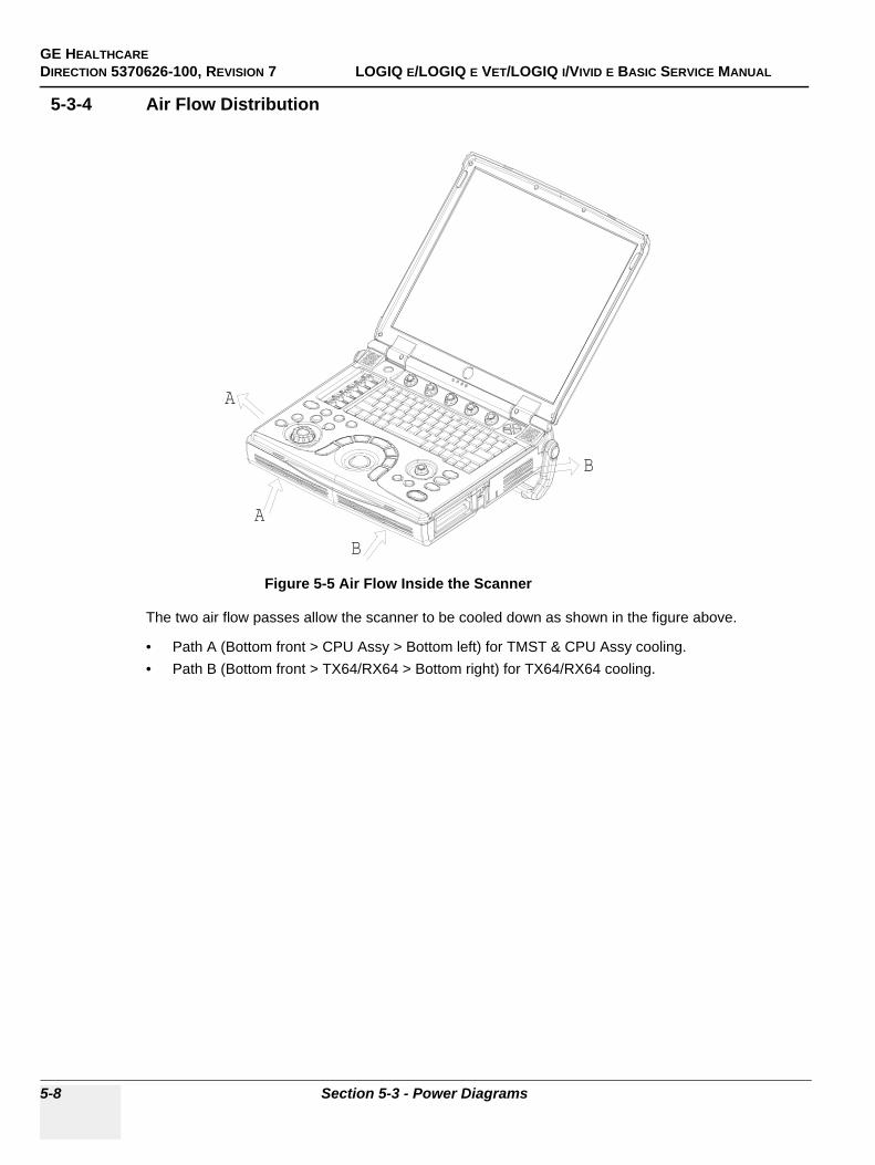
GE HEALTHCAREDIRECTION 5370626-100, REVISION 7 LOGIQ E/LOGIQ E VET/LOGIQ I/VIVID E BASIC SERVICE MANUAL
5-8 Section 5-3 - Power Diagrams
5-3-4 Air Flow Distribution
The two air flow passes allow the scanner to be cooled down as shown in the figure above.
• Path A (Bottom front > CPU Assy > Bottom left) for TMST & CPU Assy cooling.• Path B (Bottom front > TX64/RX64 > Bottom right) for TX64/RX64 cooling.
Figure 5-5 Air Flow Inside the Scanner
A
A
B
B
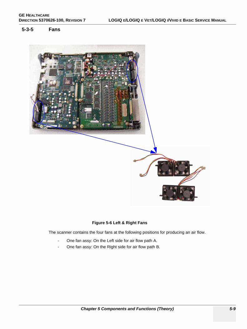
GE HEALTHCAREDIRECTION 5370626-100, REVISION 7 LOGIQ E/LOGIQ E VET/LOGIQ I/VIVID E BASIC SERVICE MANUAL
Chapter 5 Components and Functions (Theory) 5-9
5-3-5 Fans
The scanner contains the four fans at the following positions for producing an air flow.
- One fan assy: On the Left side for air flow path A.- One fan assy: On the Right side for air flow path B.
Figure 5-6 Left & Right Fans
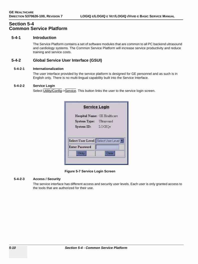
GE HEALTHCAREDIRECTION 5370626-100, REVISION 7 LOGIQ E/LOGIQ E VET/LOGIQ I/VIVID E BASIC SERVICE MANUAL
5-10 Section 5-4 - Common Service Platform
Section 5-4Common Service Platform
5-4-1 IntroductionThe Service Platform contains a set of software modules that are common to all PC backend ultrasound and cardiology systems. The Common Service Platform will increase service productivity and reduce training and service costs.
5-4-2 Global Service User Interface (GSUI)
5-4-2-1 InternationalizationThe user interface provided by the service platform is designed for GE personnel and as such is in English only. There is no multi-lingual capability built into the Service Interface.
5-4-2-2 Service LoginSelect Utility/Config->Service. This button links the user to the service login screen.
5-4-2-3 Access / SecurityThe service interface has different access and security user levels. Each user is only granted access to the tools that are authorized for their use.
Figure 5-7 Service Login Screen
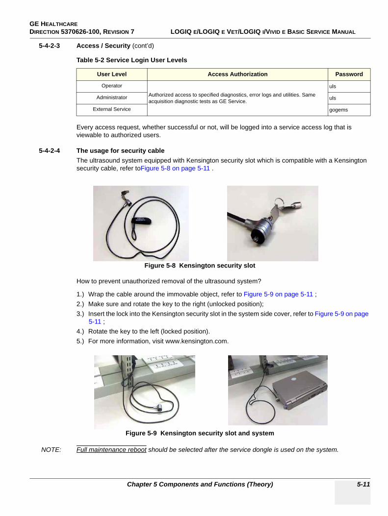
GE HEALTHCAREDIRECTION 5370626-100, REVISION 7 LOGIQ E/LOGIQ E VET/LOGIQ I/VIVID E BASIC SERVICE MANUAL
Chapter 5 Components and Functions (Theory) 5-11
5-4-2-3 Access / Security (cont’d)
Every access request, whether successful or not, will be logged into a service access log that is viewable to authorized users.
5-4-2-4 The usage for security cableThe ultrasound system equipped with Kensington security slot which is compatible with a Kensington security cable, refer toFigure 5-8 on page 5-11 .
How to prevent unauthorized removal of the ultrasound system?
1.) Wrap the cable around the immovable object, refer to Figure 5-9 on page 5-11 ;2.) Make sure and rotate the key to the right (unlocked position);3.) Insert the lock into the Kensington security slot in the system side cover, refer to Figure 5-9 on page
5-11 ;4.) Rotate the key to the left (locked position).5.) For more information, visit www.kensington.com.
NOTE: Full maintenance reboot should be selected after the service dongle is used on the system.
Table 5-2 Service Login User Levels
User Level Access Authorization Password
Operator
Authorized access to specified diagnostics, error logs and utilities. Same acquisition diagnostic tests as GE Service.
uls
Administrator uls
External Service gogems
Figure 5-8 Kensington security slot
Figure 5-9 Kensington security slot and system
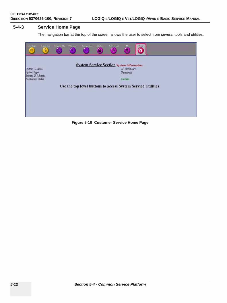
GE HEALTHCAREDIRECTION 5370626-100, REVISION 7 LOGIQ E/LOGIQ E VET/LOGIQ I/VIVID E BASIC SERVICE MANUAL
5-12 Section 5-4 - Common Service Platform
5-4-3 Service Home PageThe navigation bar at the top of the screen allows the user to select from several tools and utilities.
Figure 5-10 Customer Service Home Page
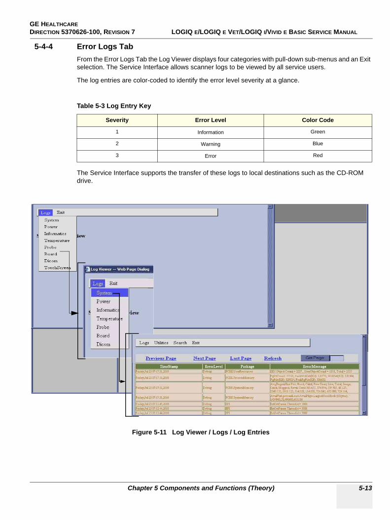
GE HEALTHCAREDIRECTION 5370626-100, REVISION 7 LOGIQ E/LOGIQ E VET/LOGIQ I/VIVID E BASIC SERVICE MANUAL
Chapter 5 Components and Functions (Theory) 5-13
5-4-4 Error Logs TabFrom the Error Logs Tab the Log Viewer displays four categories with pull-down sub-menus and an Exit selection. The Service Interface allows scanner logs to be viewed by all service users.
The log entries are color-coded to identify the error level severity at a glance.
The Service Interface supports the transfer of these logs to local destinations such as the CD-ROM drive.
Table 5-3 Log Entry Key
Severity Error Level Color Code
1 Information Green
2 Warning Blue
3 Error Red
Figure 5-11 Log Viewer / Logs / Log Entries
GE HEALTHCAREDIRECTION 5370626-100, REVISION 7 LOGIQ E/LOGIQ E VET/LOGIQ I/VIVID E BASIC SERVICE MANUAL
5-14 Section 5-4 - Common Service Platform
5-4-4-1 LogsThe seven sub-menus of the Logs category are System, Power, Infomatics, Temperature, Probe, Board, and DICOM.
NOTE: Figure 5-11 provides a graphical example of the log entries for the System Logs.
Log table headings for the different logs are as follows:
• SystemLog entry headings include Time Stamp; Error Level; Package; and Error Message.
• PowerLog entry headings include Time Stamp; Error Level; Package; and Error Message.
• InfomaticsLog entry headings include TimeStamp, Revision, PtID, PtDOB, PtSex, PtWeight, PtHeight, ExamID, Exam Category, ExamCurDate, ExamStartTime, ExamEndTime, FreezeTime, TimeOfImageArchived, AccessionNumber, RefPhyName, ReadingPhyName, Operator, RoomNo, BodyPatternSelected, InstitutionName, ActiveModeTime, CalculationMade, CalculationTime, HelpUsage, ProductName, SystemSWRev, NoOfSWModules, SystemPowerOnTime, SystemIdleTime, NoOfBoards, ProbeChangedDate, ProbeChangedTime, ProbeChangedStatus, NoOfProbeSlots, NoOfProbes, ProbeID, ProbeSerialNumber, and ActiveExamProbes.
• TemperatureLog entry headings include Time Stamp; Error Level; Package; CPU Internal Temp, TMST Process Temp, TMST Internal Temp, TMST Remote Temp, TX64 Process Temp, TX64 Internal Temp, TX64 Remote Temp, TMST 3.3V, TMST 5V, TMST 12V, TMST 1.2V, TMST 1.5V, TMST 1.8V, TX64 1.5V, TX64 1.8V, TX64 3.3V, TX 64 5V, TX649V, TX64 12V, TX 64 +THV, TX64-THV, TX64+SHV, and TX64-SHV.
• ProbeLog entry headings include Time Stamp; Error Level; Package; Error Message; Severity; Revision; and three new labels that have not yet been named.
• BoardLog entry headings include Time Stamp; Error Level; Package; Board; Severity; Revision and two new labels that have yet been named.
• DICOMLog entry headings include Time Stamp; Error Level; Package; and Error Message.
• Touch Screen (only for LOGIQ e R5.2.x)Log entry headings include Touch Screen operation events.
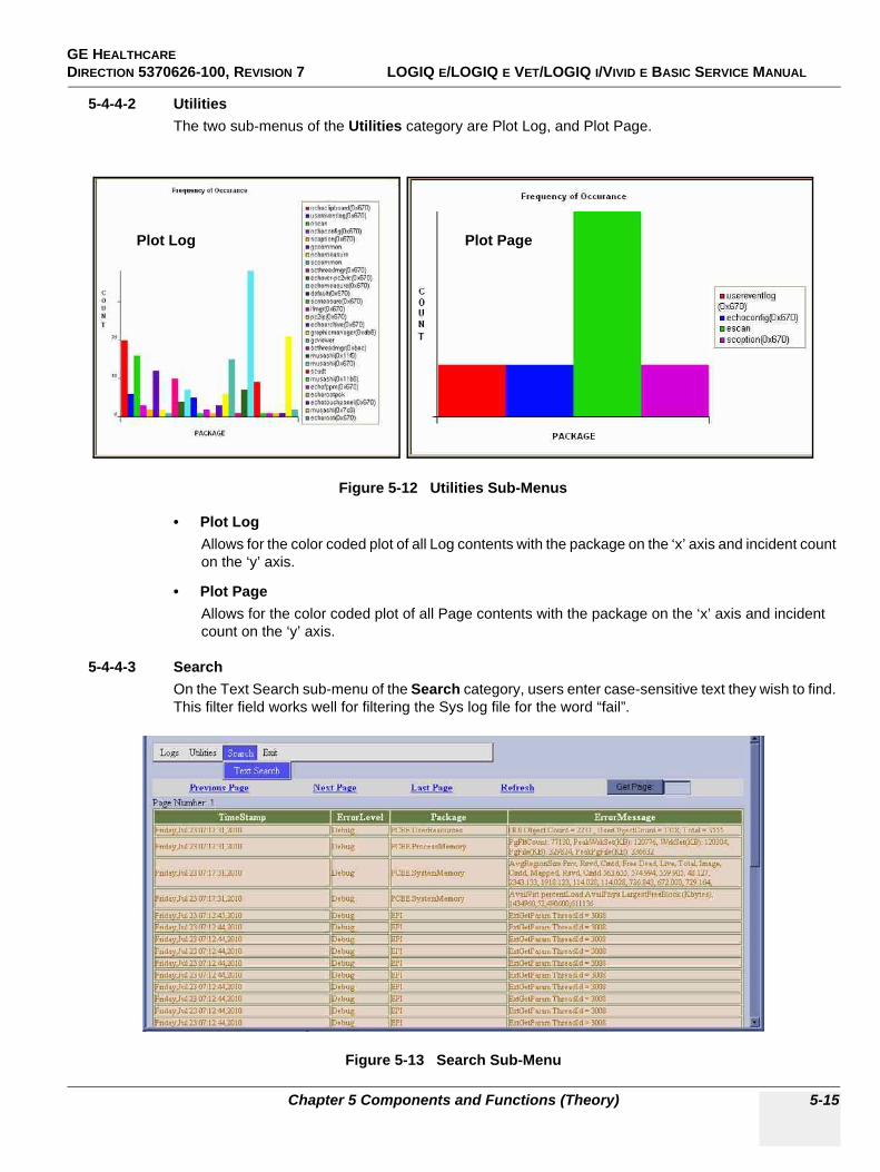
GE HEALTHCAREDIRECTION 5370626-100, REVISION 7 LOGIQ E/LOGIQ E VET/LOGIQ I/VIVID E BASIC SERVICE MANUAL
Chapter 5 Components and Functions (Theory) 5-15
5-4-4-2 UtilitiesThe two sub-menus of the Utilities category are Plot Log, and Plot Page.
• Plot LogAllows for the color coded plot of all Log contents with the package on the ‘x’ axis and incident count on the ‘y’ axis.
• Plot PageAllows for the color coded plot of all Page contents with the package on the ‘x’ axis and incident count on the ‘y’ axis.
5-4-4-3 SearchOn the Text Search sub-menu of the Search category, users enter case-sensitive text they wish to find. This filter field works well for filtering the Sys log file for the word “fail”.
Figure 5-12 Utilities Sub-Menus
Figure 5-13 Search Sub-Menu
Plot Log Plot Page
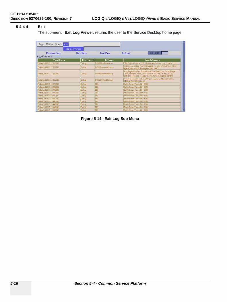
GE HEALTHCAREDIRECTION 5370626-100, REVISION 7 LOGIQ E/LOGIQ E VET/LOGIQ I/VIVID E BASIC SERVICE MANUAL
5-16 Section 5-4 - Common Service Platform
5-4-4-4 ExitThe sub-menu, Exit Log Viewer, returns the user to the Service Desktop home page.
Figure 5-14 Exit Log Sub-Menu
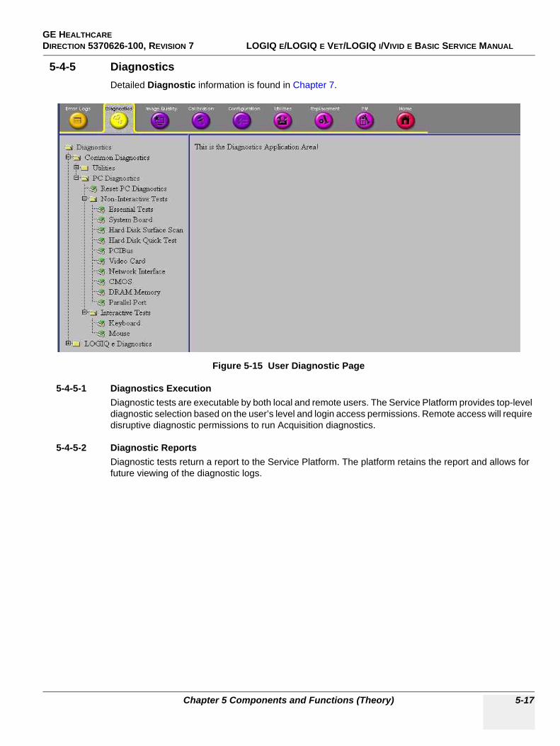
GE HEALTHCAREDIRECTION 5370626-100, REVISION 7 LOGIQ E/LOGIQ E VET/LOGIQ I/VIVID E BASIC SERVICE MANUAL
Chapter 5 Components and Functions (Theory) 5-17
5-4-5 DiagnosticsDetailed Diagnostic information is found in Chapter 7.
5-4-5-1 Diagnostics ExecutionDiagnostic tests are executable by both local and remote users. The Service Platform provides top-level diagnostic selection based on the user’s level and login access permissions. Remote access will require disruptive diagnostic permissions to run Acquisition diagnostics.
5-4-5-2 Diagnostic ReportsDiagnostic tests return a report to the Service Platform. The platform retains the report and allows for future viewing of the diagnostic logs.
Figure 5-15 User Diagnostic Page
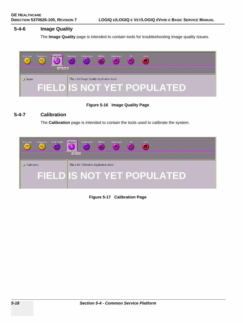
GE HEALTHCAREDIRECTION 5370626-100, REVISION 7 LOGIQ E/LOGIQ E VET/LOGIQ I/VIVID E BASIC SERVICE MANUAL
5-18 Section 5-4 - Common Service Platform
5-4-6 Image QualityThe Image Quality page is intended to contain tools for troubleshooting image quality issues.
5-4-7 CalibrationThe Calibration page is intended to contain the tools used to calibrate the system.
Figure 5-16 Image Quality Page
Figure 5-17 Calibration Page
FIELD IS NOT YET POPULATED
FIELD IS NOT YET POPULATED
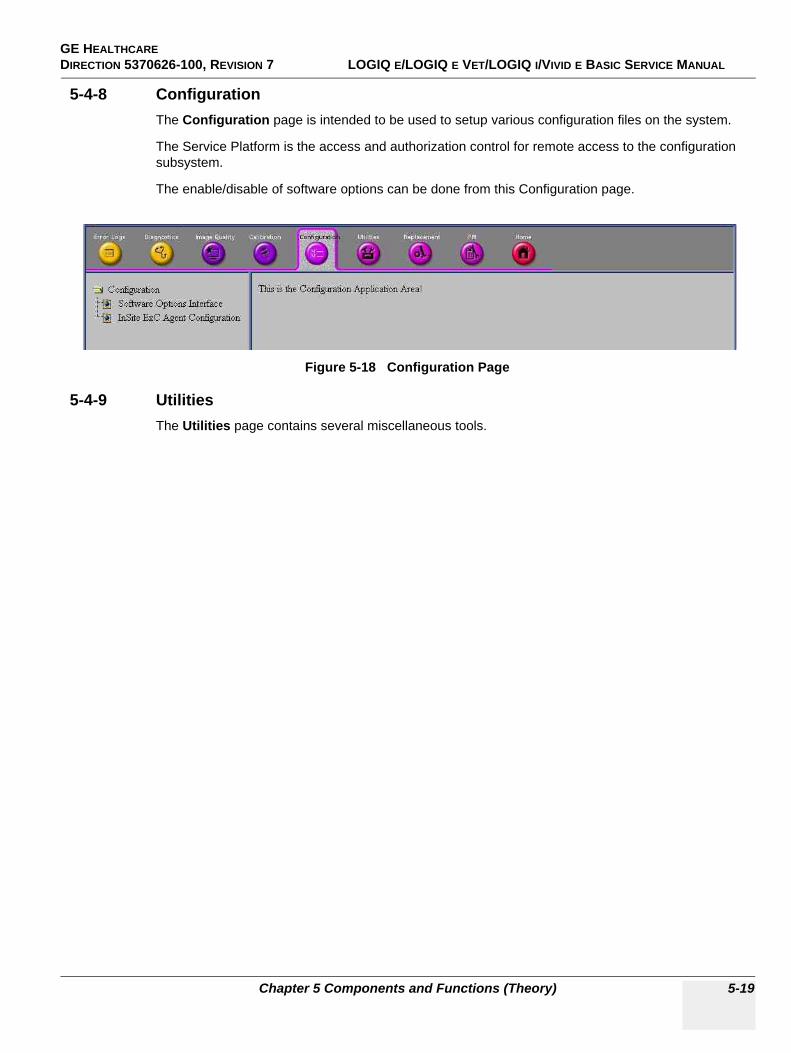
GE HEALTHCAREDIRECTION 5370626-100, REVISION 7 LOGIQ E/LOGIQ E VET/LOGIQ I/VIVID E BASIC SERVICE MANUAL
Chapter 5 Components and Functions (Theory) 5-19
5-4-8 ConfigurationThe Configuration page is intended to be used to setup various configuration files on the system.
The Service Platform is the access and authorization control for remote access to the configuration subsystem.
The enable/disable of software options can be done from this Configuration page.
5-4-9 UtilitiesThe Utilities page contains several miscellaneous tools.
Figure 5-18 Configuration Page
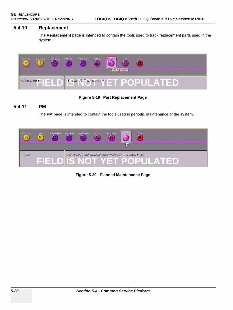
GE HEALTHCAREDIRECTION 5370626-100, REVISION 7 LOGIQ E/LOGIQ E VET/LOGIQ I/VIVID E BASIC SERVICE MANUAL
5-20 Section 5-4 - Common Service Platform
5-4-10 ReplacementThe Replacement page is intended to contain the tools used to track replacement parts used in the system.
5-4-11 PMThe PM page is intended to contain the tools used in periodic maintenance of the system.
Figure 5-19 Part Replacement Page
Figure 5-20 Planned Maintenance Page
FIELD IS NOT YET POPULATED
FIELD IS NOT YET POPULATED
GE HEALTHCARE DIRECTION 5370626-100, REVISION 7 LOGIQ E/LOGIQ E VET/LOGIQ I/VIVID E BASIC SERVICE MANUAL
Chapter 6 Service Adjustments 6-1
Chapter 6Service Adjustments
Section 6-1Overview
6-1-1 Purpose of this chapter 6This section describes how to test and adjust the scanner. These tests are optional. You may use them to check the system for errors.
Table 6-1 Contents in chapter
Section Description Page Number
6-1 Overview 6-1
6-2 Monitor Adjustments 6-2
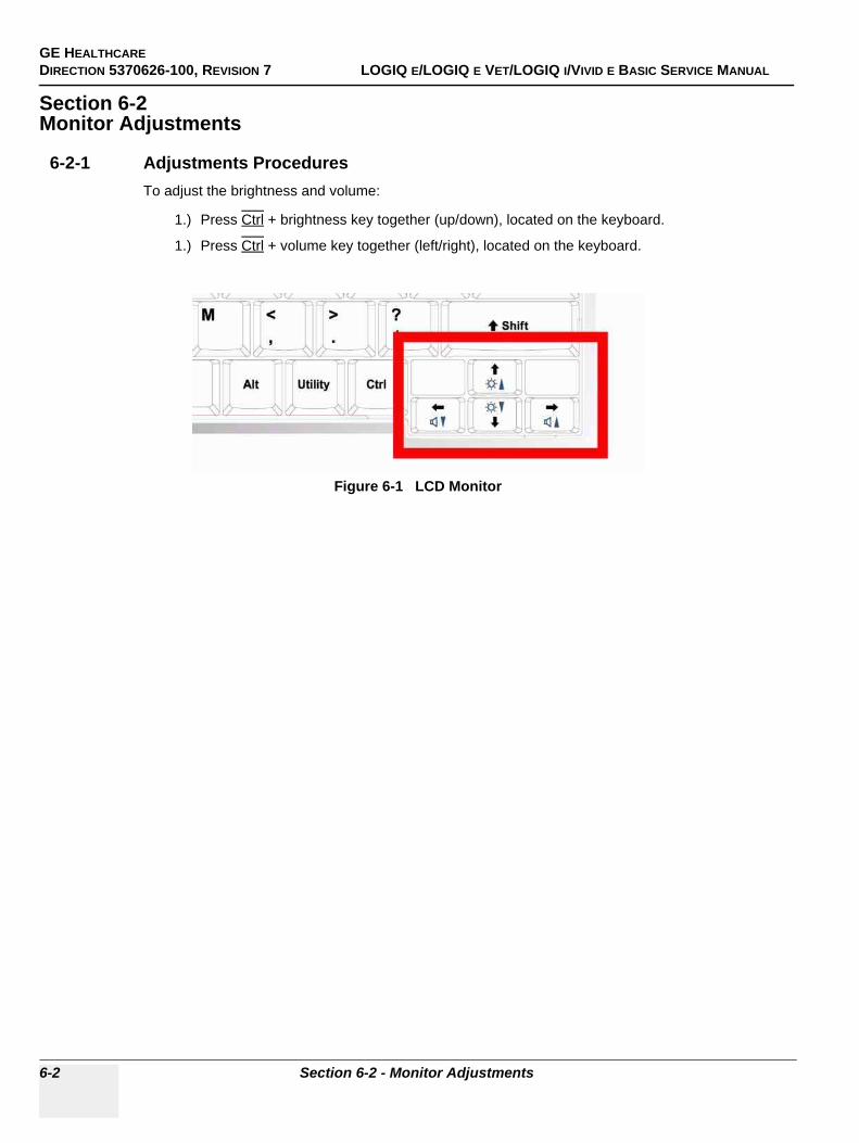
GE HEALTHCAREDIRECTION 5370626-100, REVISION 7 LOGIQ E/LOGIQ E VET/LOGIQ I/VIVID E BASIC SERVICE MANUAL
6-2 Section 6-2 - Monitor Adjustments
Section 6-2Monitor Adjustments
6-2-1 Adjustments ProceduresTo adjust the brightness and volume:
1.) Press Ctrl + brightness key together (up/down), located on the keyboard.
1.) Press Ctrl + volume key together (left/right), located on the keyboard.
Figure 6-1 LCD Monitor
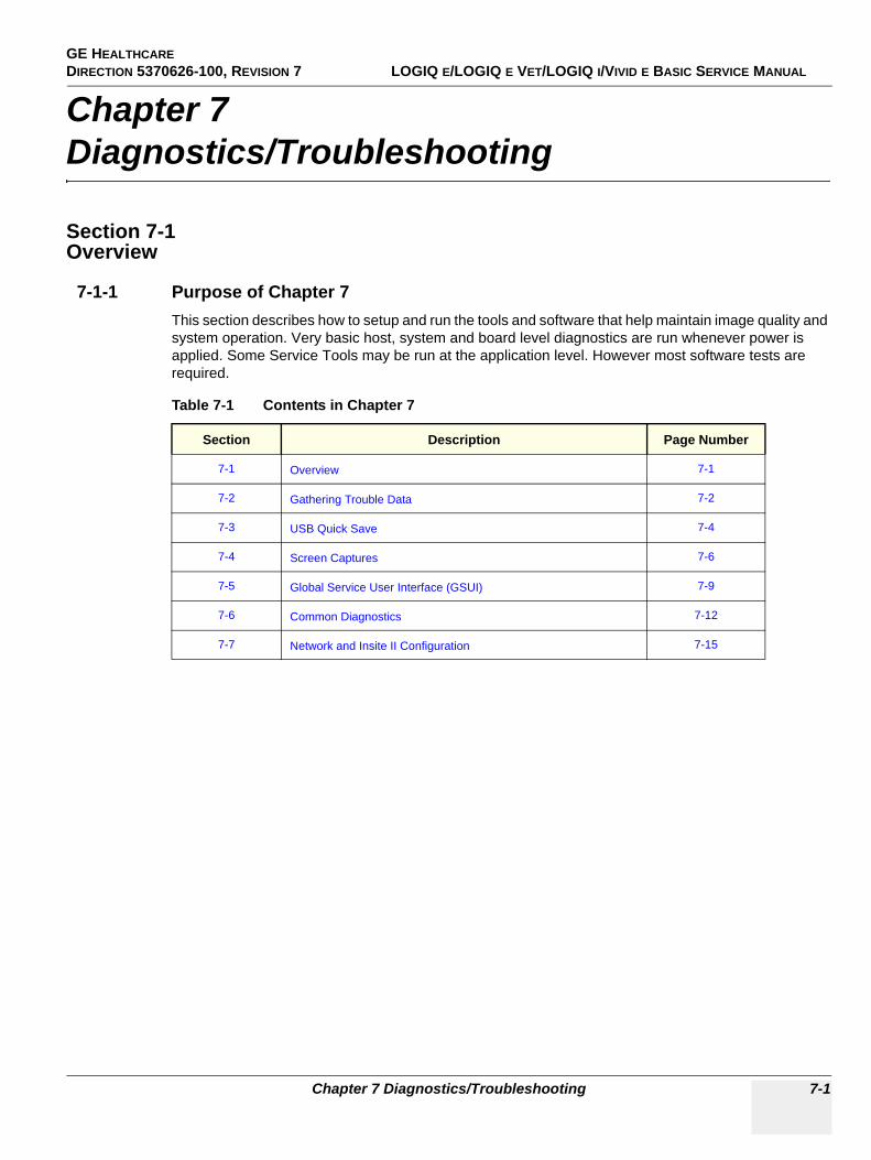
GE HEALTHCARE DIRECTION 5370626-100, REVISION 7 LOGIQ E/LOGIQ E VET/LOGIQ I/VIVID E BASIC SERVICE MANUAL
Chapter 7 Diagnostics/Troubleshooting 7-1
Chapter 7Diagnostics/Troubleshooting
Section 7-1Overview
7-1-1 Purpose of Chapter 7This section describes how to setup and run the tools and software that help maintain image quality and system operation. Very basic host, system and board level diagnostics are run whenever power is applied. Some Service Tools may be run at the application level. However most software tests are required.
Table 7-1 Contents in Chapter 7
Section Description Page Number
7-1 Overview 7-1
7-2 Gathering Trouble Data 7-2
7-3 USB Quick Save 7-4
7-4 Screen Captures 7-6
7-5 Global Service User Interface (GSUI) 7-9
7-6 Common Diagnostics 7-12
7-7 Network and Insite II Configuration 7-15
GE HEALTHCAREDIRECTION 5370626-100, REVISION 7 LOGIQ E/LOGIQ E VET/LOGIQ I/VIVID E BASIC SERVICE MANUAL
7-2 Section 7-2 - Gathering Trouble Data
Section 7-2Gathering Trouble Data
7-2-1 OverviewThere may be a time when it would be advantageous to capture trouble images and system data (logs) for acquisition to be sent back to the manufacturer for analysis. There are different options to acquire this data that would give different results.
7-2-2 Collect Vital System InformationThe following information is necessary in order to properly analyze data or images being reported as a malfunction or being returned to the manufacturer:
- Product Name = LOGIQ e/LOGIQ e Vet/LOGIQ i/Vivid e From the Utility>System>About screen:
Applications Software
- Software Version- Software Part Number
System Image Software
- Image Revision- Image Part Number
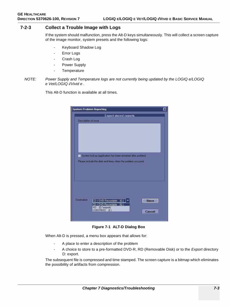
GE HEALTHCARE DIRECTION 5370626-100, REVISION 7 LOGIQ E/LOGIQ E VET/LOGIQ I/VIVID E BASIC SERVICE MANUAL
Chapter 7 Diagnostics/Troubleshooting 7-3
7-2-3 Collect a Trouble Image with LogsIf the system should malfunction, press the Alt-D keys simultaneously. This will collect a screen capture of the image monitor, system presets and the following logs:
- Keyboard Shadow Log- Error Logs- Crash Log- Power Supply- Temperature
NOTE: Power Supply and Temperature logs are not currently being updated by the LOGIQ e/LOGIQ e Vet/LOGIQ i/Vivid e .
This Alt-D function is available at all times.
When Alt-D is pressed, a menu box appears that allows for:
- A place to enter a description of the problem- A choice to store to a pre-formatted DVD-R, RD (Removable Disk) or to the Export directory
D: export.The subsequent file is compressed and time stamped. The screen capture is a bitmap which eliminates the possibility of artifacts from compression.
Figure 7-1 ALT-D Dialog Box
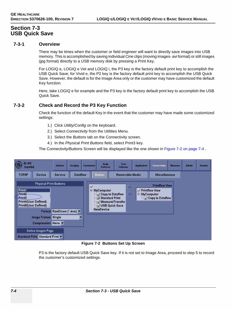
GE HEALTHCAREDIRECTION 5370626-100, REVISION 7 LOGIQ E/LOGIQ E VET/LOGIQ I/VIVID E BASIC SERVICE MANUAL
7-4 Section 7-3 - USB Quick Save
Section 7-3USB Quick Save
7-3-1 OverviewThere may be times when the customer or field engineer will want to directly save images into USB memory. This is accomplished by saving individual Cine clips (moving images- avi format) or still images (jpg format) directly to a USB memory disk by pressing a Print Key.
For LOGIQ e, LOGIQ e Vet and LOGIQ i, the P3 key is the factory default print key to accomplish the USB Quick Save; for Vivid e, the P2 key is the factory default print key to accomplish the USB Quick Save. However, the default is for the Image Area only or the customer may have customized the default Key function.
Here, take LOGIQ e for example and the P3 key is the factory default print key to accomplish the USB Quick Save.
7-3-2 Check and Record the P3 Key FunctionCheck the function of the default Key in the event that the customer may have made some customized settings.
1.) Click Utility/Config on the keyboard.2.) Select Connectivity from the Utilities Menu.3.) Select the Buttons tab on the Connectivity screen.4.) In the Physical Print Buttons field, select Print3 key.
The Connectivity/Buttons Screen will be displayed like the one shown in Figure 7-2 on page 7-4 .
P3 is the factory default USB Quick Save key. If it is not set to Image Area, proceed to step 5 to record the customer’s customized settings.
Figure 7-2 Buttons Set Up Screen
GE HEALTHCARE DIRECTION 5370626-100, REVISION 7 LOGIQ E/LOGIQ E VET/LOGIQ I/VIVID E BASIC SERVICE MANUAL
Chapter 7 Diagnostics/Troubleshooting 7-5
7-3-2 Check and Record the P3 Key Function (cont’d)
5.) In the Destinations section, record the service that is displayed. 6.) In the Physical Print Buttons section, record the parameters related to the service.
7-3-3 Setting the P3 Key to USB Quick SaveIf the P3 Key is not set to USB Quick Save:
1.) While on the Connectivity screen, with the Buttons tab displayed, go to the Destinations list.2.) From the list select USB Quick Save. Press [>>] to add the selection to the Printflow View
section.3.) Ensure that the Physical Print Buttons section for capture Area is set to Image Area and No
Image Compression.4.) The P3 Key should now be set up for USB Quick Save, sending the images directly to the USB
memory.
GE HEALTHCAREDIRECTION 5370626-100, REVISION 7 LOGIQ E/LOGIQ E VET/LOGIQ I/VIVID E BASIC SERVICE MANUAL
7-6 Section 7-4 - Screen Captures
Section 7-4Screen Captures
There may be times when the customer or field engineer will want to capture a presentation on the screen. This is accomplished by first saving the image(s) to the clipboard using a Print Key.
There’s no factory default print key to accomplish a secondary screen capture. However, customer may have customize any of Print Key function. Here, take Print1 button for example, for LOGIQ e, LOGIQ e Vet, LOGIQ i, Print1, Print 2 and Print3 are the same, for Vivid e, Store, Print1 and Print2 are the same. Therefore, screen capture should involve the following steps:
1.) Check and record any custom settings for the Print1 button.2.) Set the Print1 button to Whole Screen, Secondary Capture.3.) Capture the required screens to the Hard Disk Drive or DVD-R.4.) Restore the Print1 button to it’s original settings.
7-4-1 Check and Record the P1 Key FunctionCheck the function of the Print1 Key in the event that the customer may have made some custom settings.
1.) Click Utility/Config on the keyboard.2.) Select Connectivity from the Utilities Menu.3.) Select the Buttons tab on the Connectivity screen.4.) In the Physical Print Buttons field, select Print1.
The Connectivity/Buttons Screen will be displayed like the one shown in Figure 7-2 on page 7-4 .
If P1 is not set to Whole Screen, as shown in Figure 7-2, proceed to step 5 to record the customer’s customized settings.
5.) In the Destinations section, record the service that is displayed. 6.) In the Physical Print Buttons section, record the parameters related to the service.
7-4-2 Setting the P1 Key to Screen CaptureIf the P1 Key is not set to screen capture:
1.) While on the Connectivity screen, with the Buttons tab displayed, go to the Destinations list.2.) From the list select Copy To Dataflow. Press [>>] to add the selection to the Printflow View
section.3.) Ensure that the Physical Print Buttons section for capture Area is set to Whole Screen,
secondary Capture and No Image Compression.4.) The P1 Key should now be set up for whole screen capture, sending the screens to the image
buffer (clipboard).
7-4-3 Capturing a ScreenThe following is a generic process to capture any screen from the scanner:
1.) Navigate to and display the image/screen to be captured.2.) Press P1. This will place a snapshot of the screen on the “clipboard” displayed at the bottom
of the scan image display.
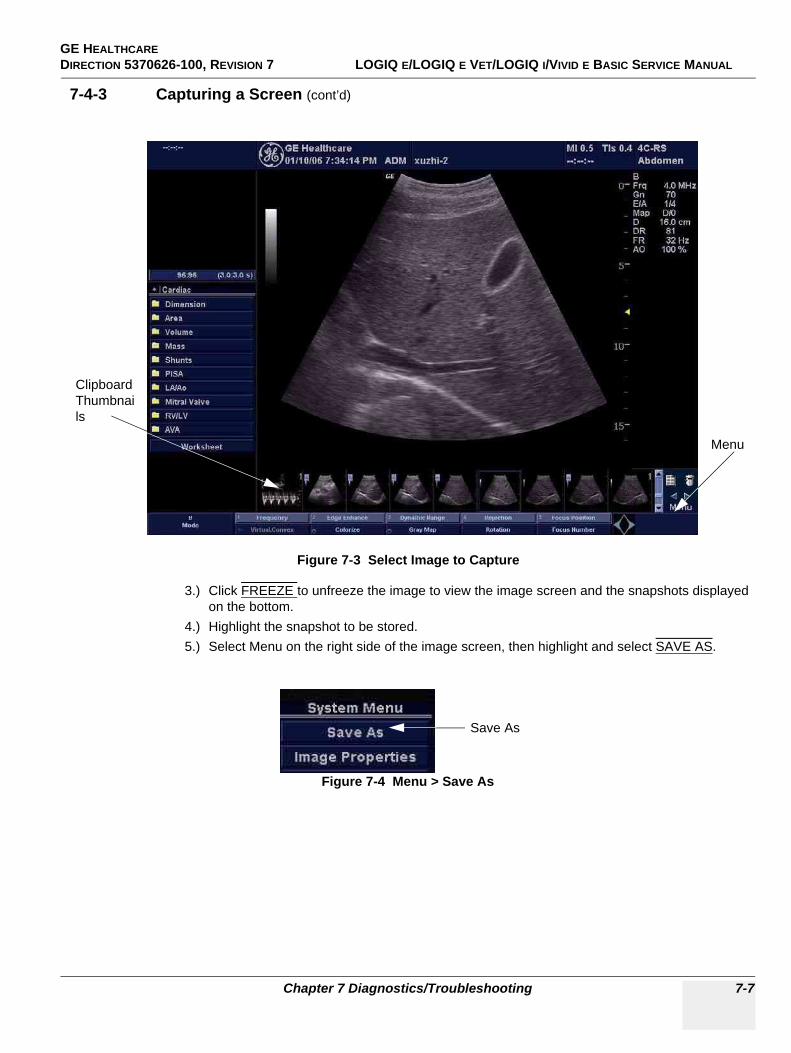
GE HEALTHCARE DIRECTION 5370626-100, REVISION 7 LOGIQ E/LOGIQ E VET/LOGIQ I/VIVID E BASIC SERVICE MANUAL
Chapter 7 Diagnostics/Troubleshooting 7-7
7-4-3 Capturing a Screen (cont’d)
3.) Click FREEZE to unfreeze the image to view the image screen and the snapshots displayed on the bottom.
4.) Highlight the snapshot to be stored.5.) Select Menu on the right side of the image screen, then highlight and select SAVE AS.
Figure 7-3 Select Image to Capture
Figure 7-4 Menu > Save As
Clipboard Thumbnails
Menu
Save As
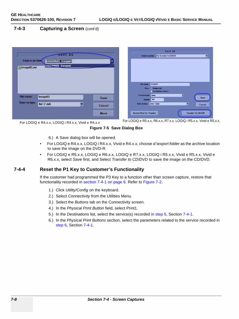
GE HEALTHCAREDIRECTION 5370626-100, REVISION 7 LOGIQ E/LOGIQ E VET/LOGIQ I/VIVID E BASIC SERVICE MANUAL
7-8 Section 7-4 - Screen Captures
7-4-3 Capturing a Screen (cont’d)
6.) A Save dialog box will be opened.• For LOGIQ e R4.x.x, LOGIQ i R4.x.x, Vivid e R4.x.x, choose d:\export folder as the archive location
to save the image on the DVD-R.• For LOGIQ e R5.x.x, LOGIQ e R6.x.x, LOGIQ e R7.x.x, LOGIQ i R5.x.x, Vivid e R5.x.x, Vivid e
R6.x.x, select Save first, and Select Transfer to CD/DVD to save the image on the CD/DVD.
7-4-4 Reset the P1 Key to Customer’s FunctionalityIf the customer had programmed the P3 Key to a function other than screen capture, restore that functionality recorded in section 7-4-1 on page 6. Refer to Figure 7-2.
1.) Click Utility/Config on the keyboard.2.) Select Connectivity from the Utilities Menu.3.) Select the Buttons tab on the Connectivity screen.4.) In the Physical Print Button field, select Print1.5.) In the Destinations list, select the service(s) recorded in step 5, Section 7-4-1. 6.) In the Physical Print Buttons section, select the parameters related to the service recorded in
step 6, Section 7-4-1.
Figure 7-5 Save Dialog BoxFor LOGIQ e R4.x.x, LOGIQ i R4.x.x, Vivid e R4.x.x For LOGIQ e R5.x.x, R6.x.x, R7.x.x, LOGIQ i R5.x.x, Vivid e R5.x.x,
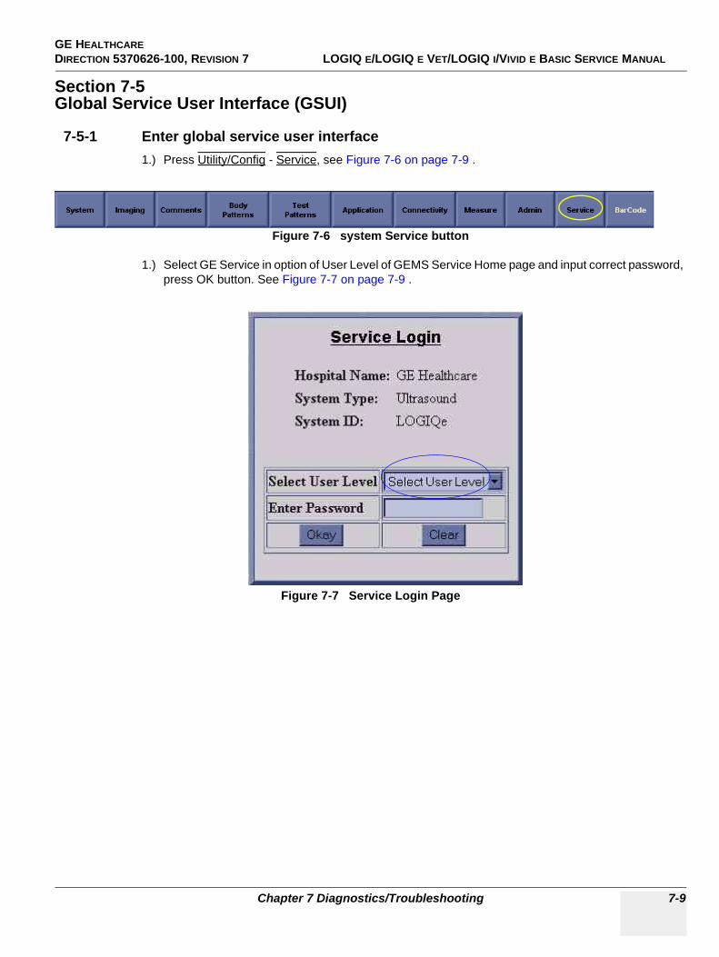
GE HEALTHCARE DIRECTION 5370626-100, REVISION 7 LOGIQ E/LOGIQ E VET/LOGIQ I/VIVID E BASIC SERVICE MANUAL
Chapter 7 Diagnostics/Troubleshooting 7-9
Section 7-5Global Service User Interface (GSUI)
7-5-1 Enter global service user interface1.) Press Utility/Config - Service, see Figure 7-6 on page 7-9 .
1.) Select GE Service in option of User Level of GEMS Service Home page and input correct password, press OK button. See Figure 7-7 on page 7-9 .
Figure 7-6 system Service button
Figure 7-7 Service Login Page
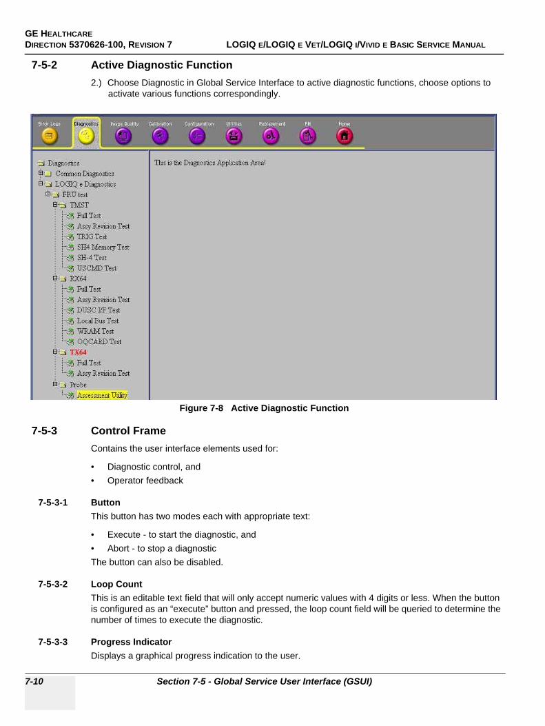
GE HEALTHCAREDIRECTION 5370626-100, REVISION 7 LOGIQ E/LOGIQ E VET/LOGIQ I/VIVID E BASIC SERVICE MANUAL
7-10 Section 7-5 - Global Service User Interface (GSUI)
7-5-2 Active Diagnostic Function2.) Choose Diagnostic in Global Service Interface to active diagnostic functions, choose options to
activate various functions correspondingly.
7-5-3 Control FrameContains the user interface elements used for:
• Diagnostic control, and• Operator feedback
7-5-3-1 ButtonThis button has two modes each with appropriate text:
• Execute - to start the diagnostic, and• Abort - to stop a diagnosticThe button can also be disabled.
7-5-3-2 Loop CountThis is an editable text field that will only accept numeric values with 4 digits or less. When the button is configured as an “execute” button and pressed, the loop count field will be queried to determine the number of times to execute the diagnostic.
7-5-3-3 Progress IndicatorDisplays a graphical progress indication to the user.
Figure 7-8 Active Diagnostic Function

GE HEALTHCARE DIRECTION 5370626-100, REVISION 7 LOGIQ E/LOGIQ E VET/LOGIQ I/VIVID E BASIC SERVICE MANUAL
Chapter 7 Diagnostics/Troubleshooting 7-11
7-5-3-4 Short Text MessageDisplays either a starting message or aborting message, as well as the diagnostic completion status.
7-5-3-5 Background ColorInitially gray, the Control Frame background color changes upon completion of a diagnostic to indicate completion status.
• Fail = Red• Pass = Green• Neither pass nor fail = Set back to Gray (for example, final code status is Aborted).
GE HEALTHCAREDIRECTION 5370626-100, REVISION 7 LOGIQ E/LOGIQ E VET/LOGIQ I/VIVID E BASIC SERVICE MANUAL
7-12 Section 7-6 - Common Diagnostics
Section 7-6Common Diagnostics
7-6-1 UtilitiesProvides two selections:
7-6-1-1 Disruptive ModeAllows you to enable or disable disruptive mode troubleshooting.
7-6-1-2 System ShutdownAllows for system shutdown from the diagnostic menu. Select to Restart System or Shutdown System. Also, select to retain Disruptive Mode or Not.
After submitting to restart or shutdown a confirmation screen gives one last chance to confirm or cancel the request.
GE HEALTHCARE DIRECTION 5370626-100, REVISION 7 LOGIQ E/LOGIQ E VET/LOGIQ I/VIVID E BASIC SERVICE MANUAL
Chapter 7 Diagnostics/Troubleshooting 7-13
7-6-2 PC Diagnostics (Non-Interactive Tests)
7-6-2-1 Essential Tests
7-6-2-2 System Board
7-6-2-3 Hard Disk Drive Surface Scan
7-6-2-4 Hard Disk Drive Quick Test
7-6-2-5 PCIBus
7-6-2-6 Video Card
7-6-2-7 Network Interface
7-6-2-8 CMOS
7-6-2-9 DRAM Memory
7-6-2-10 Parallel Port
GE HEALTHCAREDIRECTION 5370626-100, REVISION 7 LOGIQ E/LOGIQ E VET/LOGIQ I/VIVID E BASIC SERVICE MANUAL
7-14 Section 7-6 - Common Diagnostics
7-6-3 PC Diagnostics (Interactive Tests)
7-6-3-1 Keyboard Test
7-6-3-2 Mouse Test
7-6-3-3 Audio Card Test (only for LOGIQ e R5.2.x and R6.x.x)
7-6-4 Restart the system after diagnosticsAlways shutdown the system and reboot after a diagnostics session.
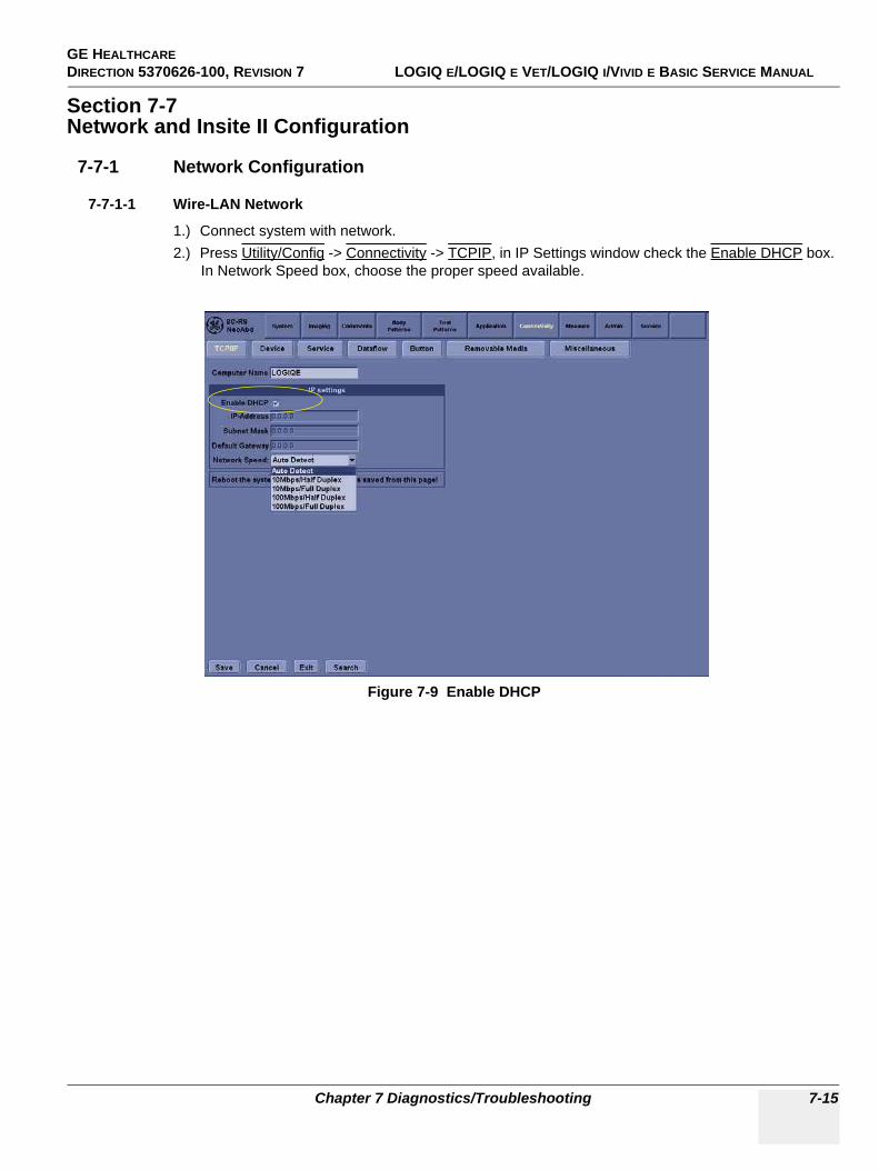
GE HEALTHCARE DIRECTION 5370626-100, REVISION 7 LOGIQ E/LOGIQ E VET/LOGIQ I/VIVID E BASIC SERVICE MANUAL
Chapter 7 Diagnostics/Troubleshooting 7-15
Section 7-7Network and Insite II Configuration
7-7-1 Network Configuration
7-7-1-1 Wire-LAN Network
1.) Connect system with network.2.) Press Utility/Config -> Connectivity -> TCPIP, in IP Settings window check the Enable DHCP box.
In Network Speed box, choose the proper speed available.
Figure 7-9 Enable DHCP
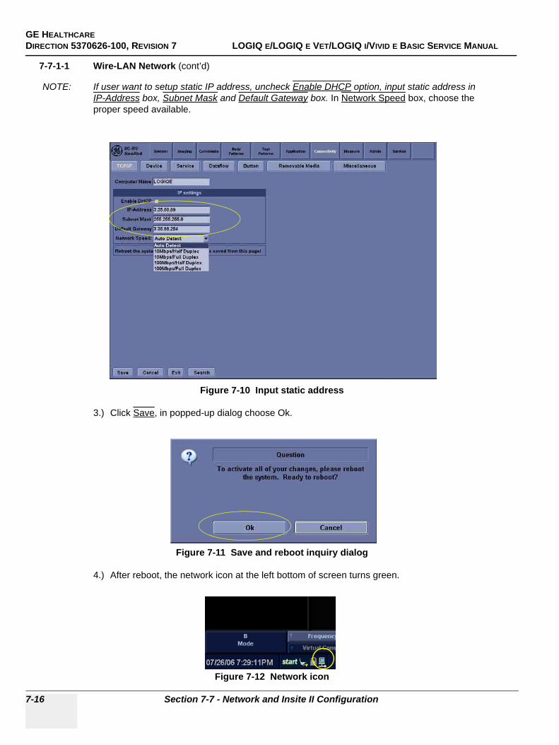
GE HEALTHCAREDIRECTION 5370626-100, REVISION 7 LOGIQ E/LOGIQ E VET/LOGIQ I/VIVID E BASIC SERVICE MANUAL
7-16 Section 7-7 - Network and Insite II Configuration
7-7-1-1 Wire-LAN Network (cont’d)
NOTE: If user want to setup static IP address, uncheck Enable DHCP option, input static address in IP-Address box, Subnet Mask and Default Gateway box. In Network Speed box, choose the proper speed available.
3.) Click Save, in popped-up dialog choose Ok.
4.) After reboot, the network icon at the left bottom of screen turns green.
Figure 7-10 Input static address
Figure 7-11 Save and reboot inquiry dialog
Figure 7-12 Network icon
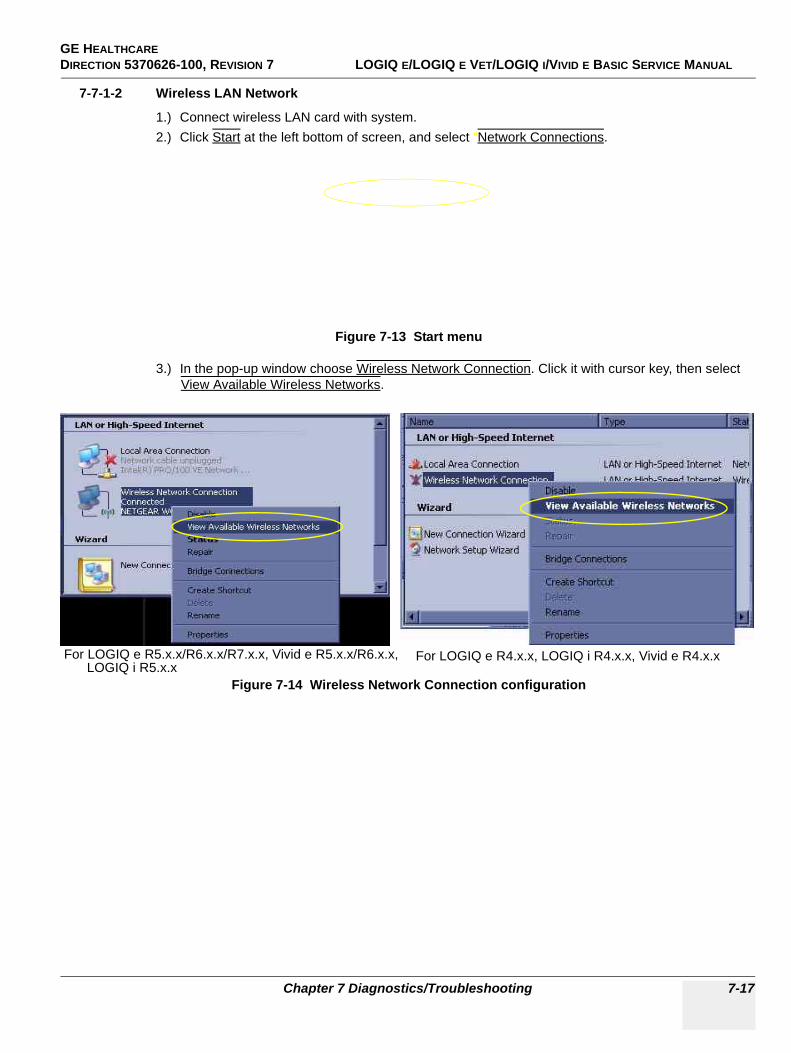
GE HEALTHCARE DIRECTION 5370626-100, REVISION 7 LOGIQ E/LOGIQ E VET/LOGIQ I/VIVID E BASIC SERVICE MANUAL
Chapter 7 Diagnostics/Troubleshooting 7-17
7-7-1-2 Wireless LAN Network
1.) Connect wireless LAN card with system.2.) Click Start at the left bottom of screen, and select “Network Connections.
3.) In the pop-up window choose Wireless Network Connection. Click it with cursor key, then select View Available Wireless Networks.
Figure 7-13 Start menu
Figure 7-14 Wireless Network Connection configuration
For LOGIQ e R5.x.x/R6.x.x/R7.x.x, Vivid e R5.x.x/R6.x.x, LOGIQ i R5.x.x
For LOGIQ e R4.x.x, LOGIQ i R4.x.x, Vivid e R4.x.x
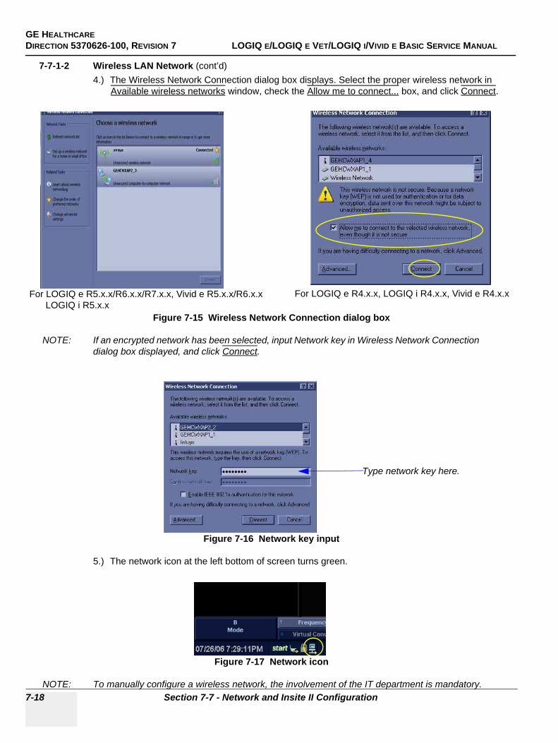
GE HEALTHCAREDIRECTION 5370626-100, REVISION 7 LOGIQ E/LOGIQ E VET/LOGIQ I/VIVID E BASIC SERVICE MANUAL
7-18 Section 7-7 - Network and Insite II Configuration
7-7-1-2 Wireless LAN Network (cont’d)4.) The Wireless Network Connection dialog box displays. Select the proper wireless network in
Available wireless networks window, check the Allow me to connect... box, and click Connect.
NOTE: If an encrypted network has been selected, input Network key in Wireless Network Connection dialog box displayed, and click Connect.
5.) The network icon at the left bottom of screen turns green.
Figure 7-15 Wireless Network Connection dialog box
Figure 7-16 Network key input
Figure 7-17 Network icon
NOTE: To manually configure a wireless network, the involvement of the IT department is mandatory.
For LOGIQ e R5.x.x/R6.x.x/R7.x.x, Vivid e R5.x.x/R6.x.x For LOGIQ e R4.x.x, LOGIQ i R4.x.x, Vivid e R4.x.x LOGIQ i R5.x.x
Type network key here.

GE HEALTHCARE DIRECTION 5370626-100, REVISION 7 LOGIQ E/LOGIQ E VET/LOGIQ I/VIVID E BASIC SERVICE MANUAL
Chapter 7 Diagnostics/Troubleshooting 7-19
7-7-2 Insite II Configuration6.) Enter global service user interface, and log in as GE Service. See section 7-5-1 on page 9.7.) To use Pilot Server, on Configuration page, choose Questra Agent Configuration in left column.
Select Advanced Configuration, then choose “Others” as server type, and manually input pilot address, and click SAVE.
NOTE: If system is within GE network, choose Development as server type, and do not need step 9.) enter Proxy Server address.
Figure 7-18 Advanced_Configuration page (out of GE network)
Figure 7-19 Advanced_Configuration page (within GE network)
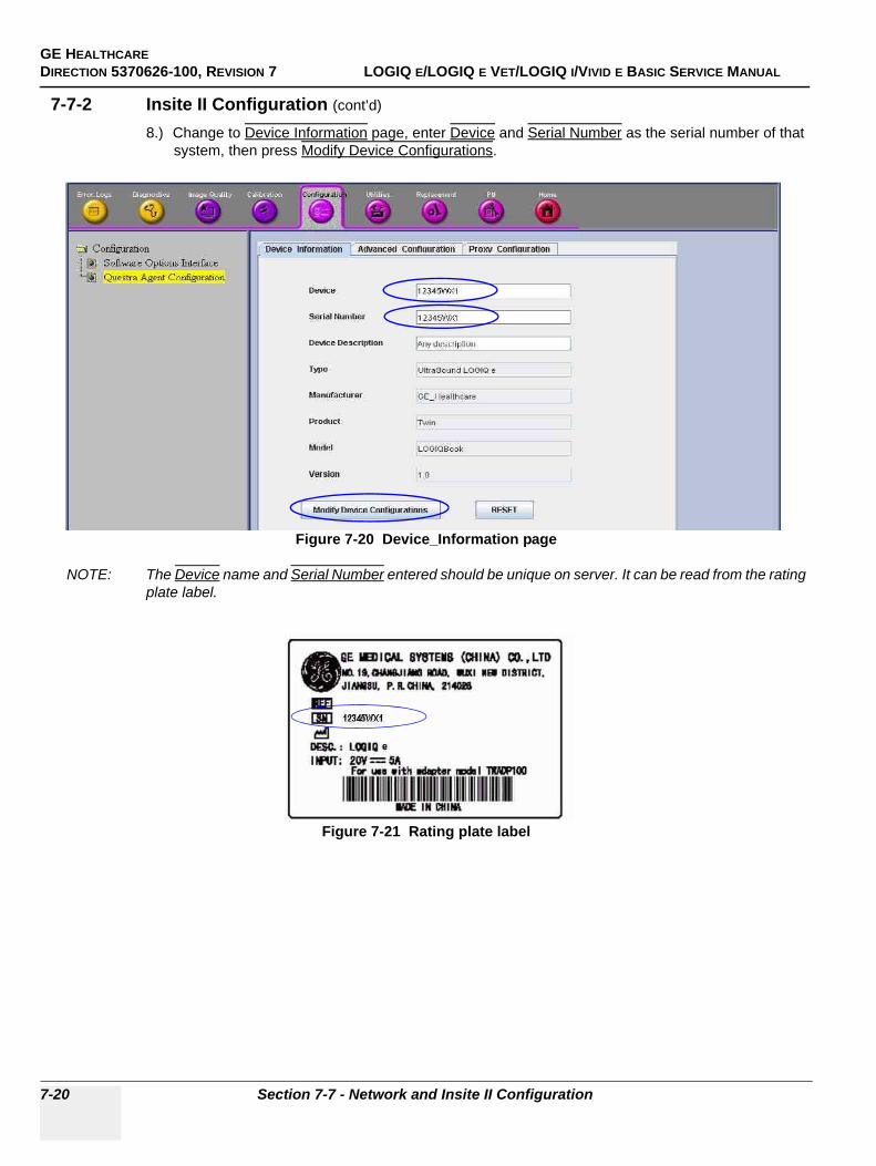
GE HEALTHCAREDIRECTION 5370626-100, REVISION 7 LOGIQ E/LOGIQ E VET/LOGIQ I/VIVID E BASIC SERVICE MANUAL
7-20 Section 7-7 - Network and Insite II Configuration
7-7-2 Insite II Configuration (cont’d)
8.) Change to Device Information page, enter Device and Serial Number as the serial number of that system, then press Modify Device Configurations.
NOTE: The Device name and Serial Number entered should be unique on server. It can be read from the rating plate label.
Figure 7-20 Device_Information page
Figure 7-21 Rating plate label
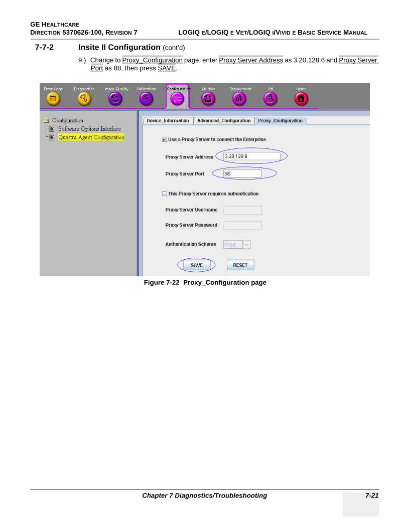
GE HEALTHCARE DIRECTION 5370626-100, REVISION 7 LOGIQ E/LOGIQ E VET/LOGIQ I/VIVID E BASIC SERVICE MANUAL
Chapter 7 Diagnostics/Troubleshooting 7-21
7-7-2 Insite II Configuration (cont’d)
9.) Change to Proxy_Configuration page, enter Proxy Server Address as 3.20.128.6 and Proxy Server Port as 88, then press SAVE.
Figure 7-22 Proxy_Configuration page
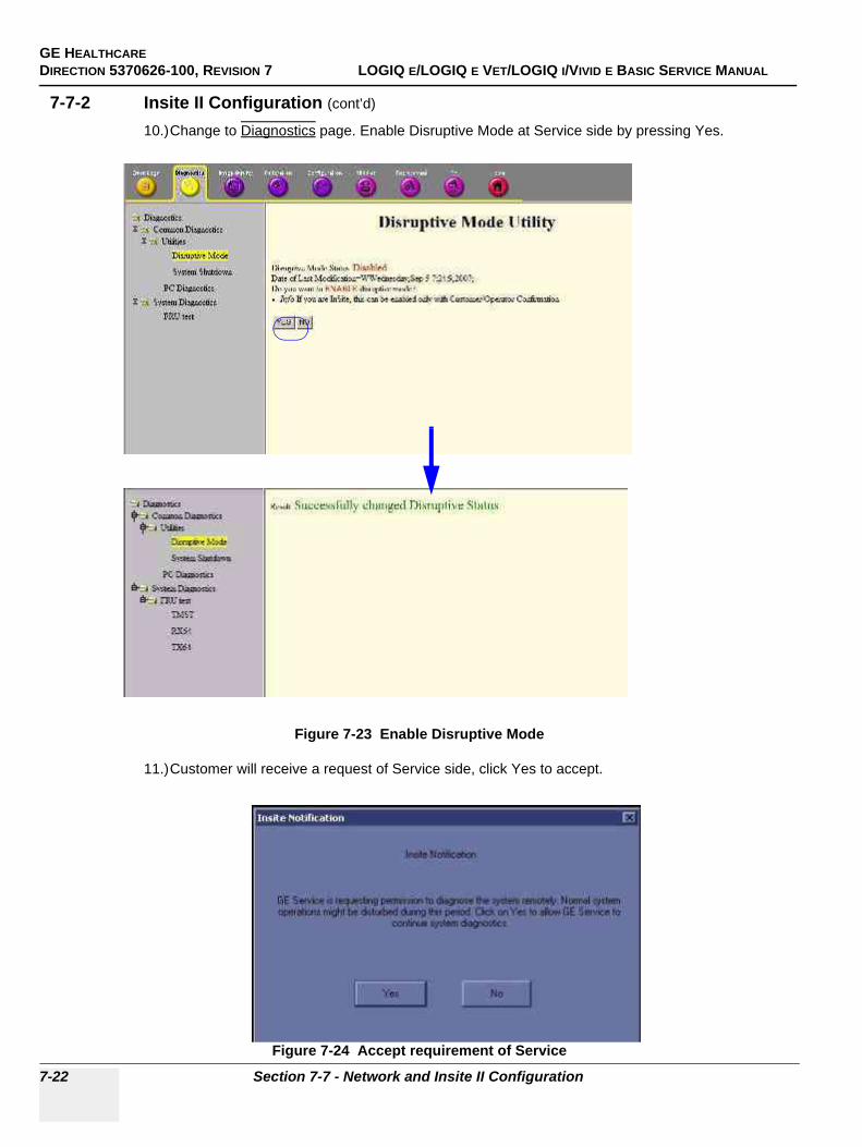
GE HEALTHCAREDIRECTION 5370626-100, REVISION 7 LOGIQ E/LOGIQ E VET/LOGIQ I/VIVID E BASIC SERVICE MANUAL
7-22 Section 7-7 - Network and Insite II Configuration
7-7-2 Insite II Configuration (cont’d)
10.)Change to Diagnostics page. Enable Disruptive Mode at Service side by pressing Yes.
11.)Customer will receive a request of Service side, click Yes to accept.
Figure 7-23 Enable Disruptive Mode
Figure 7-24 Accept requirement of Service
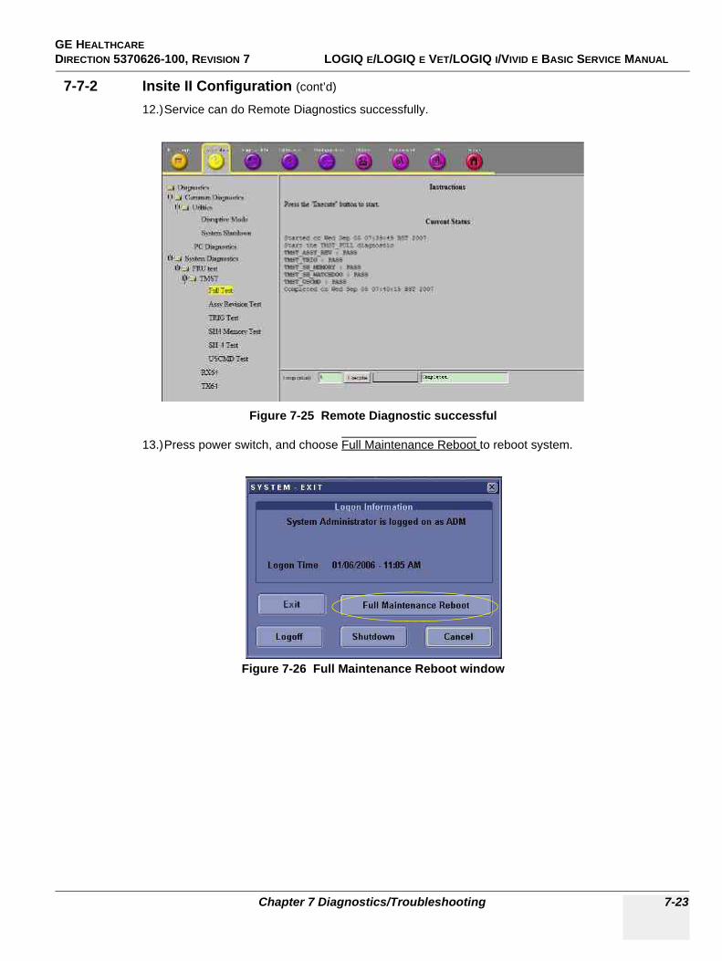
GE HEALTHCARE DIRECTION 5370626-100, REVISION 7 LOGIQ E/LOGIQ E VET/LOGIQ I/VIVID E BASIC SERVICE MANUAL
Chapter 7 Diagnostics/Troubleshooting 7-23
7-7-2 Insite II Configuration (cont’d)
12.)Service can do Remote Diagnostics successfully.
13.)Press power switch, and choose Full Maintenance Reboot to reboot system.
Figure 7-25 Remote Diagnostic successful
Figure 7-26 Full Maintenance Reboot window
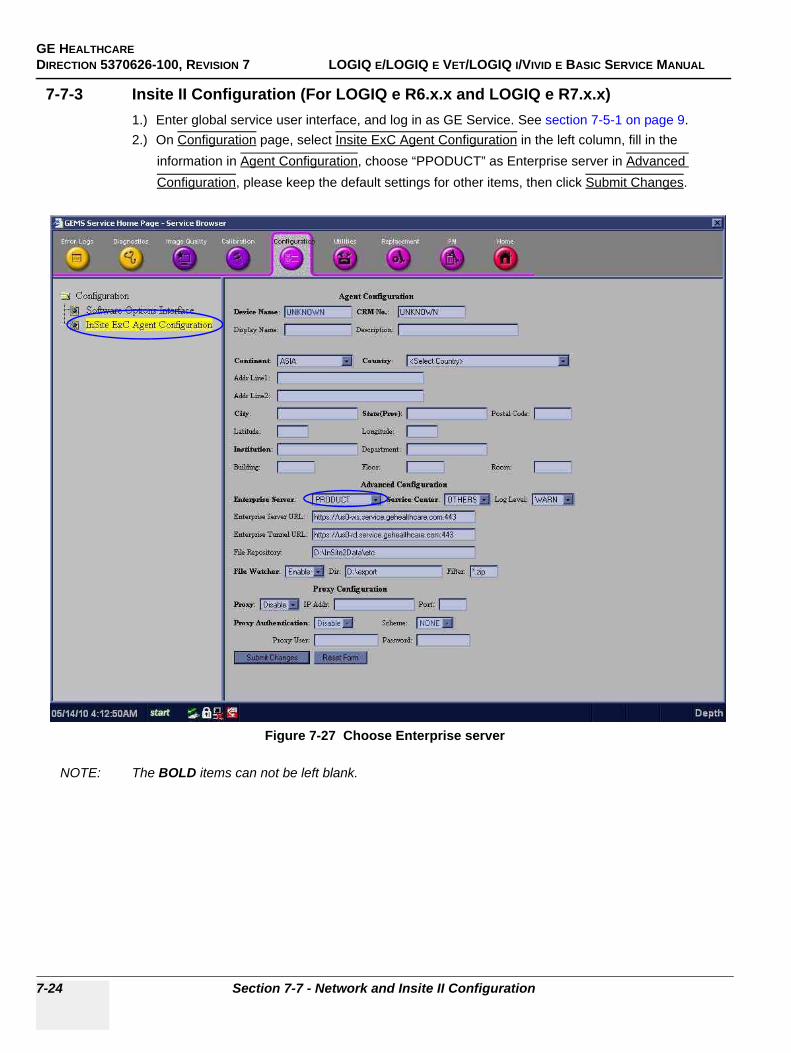
GE HEALTHCAREDIRECTION 5370626-100, REVISION 7 LOGIQ E/LOGIQ E VET/LOGIQ I/VIVID E BASIC SERVICE MANUAL
7-24 Section 7-7 - Network and Insite II Configuration
7-7-3 Insite II Configuration (For LOGIQ e R6.x.x and LOGIQ e R7.x.x)1.) Enter global service user interface, and log in as GE Service. See section 7-5-1 on page 9.2.) On Configuration page, select Insite ExC Agent Configuration in the left column, fill in the
information in Agent Configuration, choose “PPODUCT” as Enterprise server in Advanced Configuration, please keep the default settings for other items, then click Submit Changes.
NOTE: The BOLD items can not be left blank.
Figure 7-27 Choose Enterprise server

GE HEALTHCARE DIRECTION 5370626-100, REVISION 7 LOGIQ E/LOGIQ E VET/LOGIQ I/VIVID E BASIC SERVICE MANUAL
Chapter 7 Diagnostics/Troubleshooting 7-25
7-7-3 Insite II Configuration (For LOGIQ e R6.x.x and LOGIQ e R7.x.x) (cont’d)
3.) Set Disruptive Mode Status as Enabled. Change to Utilities page. select Disruptive Mode in the left column, Check whether the Disruptive Mode Status is Enabled, if not, click Yes to change the Disruptive Mode Status as Enabled. See Figure 7-28 on page 7-25 .
There is another way to Set Disruptive Mode Status as Enabled. Click Insite Icon in system status bar, choose Connect clinical Lifeline, the Insite Icon will change to RED, do not need to change if the insite icon is already RED. See Figure 7-29 on page 7-25 .
Figure 7-28 Device_Information page
Figure 7-29 Set Disruptive Mode Status
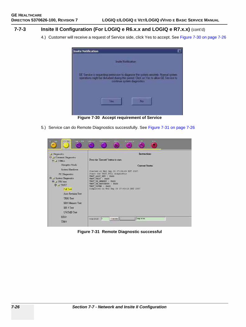
GE HEALTHCAREDIRECTION 5370626-100, REVISION 7 LOGIQ E/LOGIQ E VET/LOGIQ I/VIVID E BASIC SERVICE MANUAL
7-26 Section 7-7 - Network and Insite II Configuration
7-7-3 Insite II Configuration (For LOGIQ e R6.x.x and LOGIQ e R7.x.x) (cont’d)
4.) Customer will receive a request of Service side, click Yes to accept. See Figure 7-30 on page 7-26
5.) Service can do Remote Diagnostics successfully. See Figure 7-31 on page 7-26
Figure 7-30 Accept requirement of Service
Figure 7-31 Remote Diagnostic successful
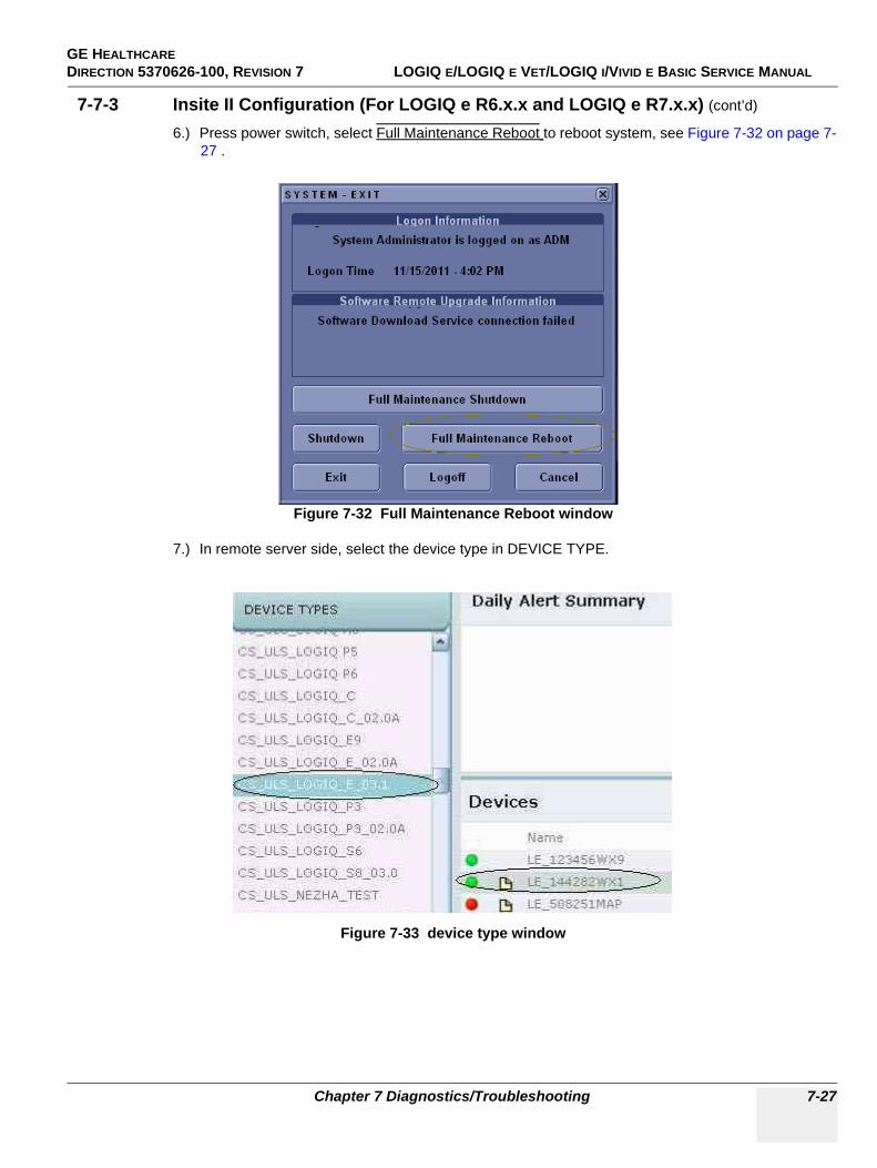
GE HEALTHCARE DIRECTION 5370626-100, REVISION 7 LOGIQ E/LOGIQ E VET/LOGIQ I/VIVID E BASIC SERVICE MANUAL
Chapter 7 Diagnostics/Troubleshooting 7-27
7-7-3 Insite II Configuration (For LOGIQ e R6.x.x and LOGIQ e R7.x.x) (cont’d)
6.) Press power switch, select Full Maintenance Reboot to reboot system, see Figure 7-32 on page 7-27 .
7.) In remote server side, select the device type in DEVICE TYPE.
Figure 7-32 Full Maintenance Reboot window
Figure 7-33 device type window
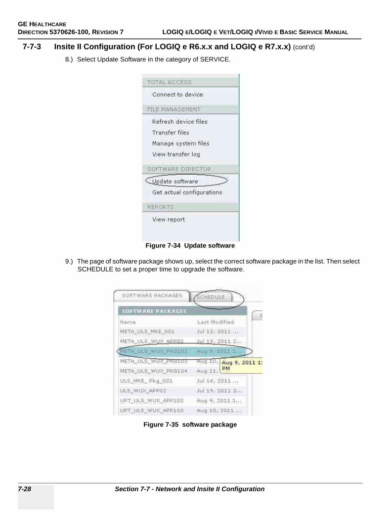
GE HEALTHCAREDIRECTION 5370626-100, REVISION 7 LOGIQ E/LOGIQ E VET/LOGIQ I/VIVID E BASIC SERVICE MANUAL
7-28 Section 7-7 - Network and Insite II Configuration
7-7-3 Insite II Configuration (For LOGIQ e R6.x.x and LOGIQ e R7.x.x) (cont’d)
8.) Select Update Software in the category of SERVICE.
9.) The page of software package shows up, select the correct software package in the list. Then select SCHEDULE to set a proper time to upgrade the software.
Figure 7-34 Update software
Figure 7-35 software package
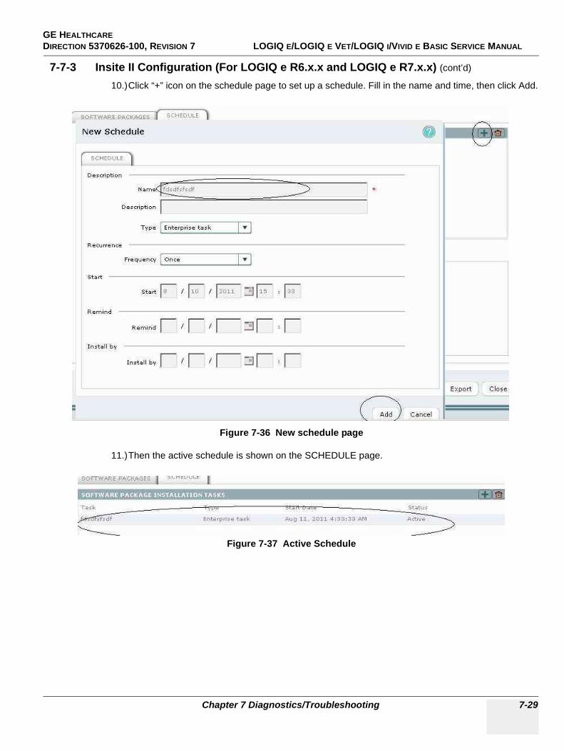
GE HEALTHCARE DIRECTION 5370626-100, REVISION 7 LOGIQ E/LOGIQ E VET/LOGIQ I/VIVID E BASIC SERVICE MANUAL
Chapter 7 Diagnostics/Troubleshooting 7-29
7-7-3 Insite II Configuration (For LOGIQ e R6.x.x and LOGIQ e R7.x.x) (cont’d)
10.)Click “+” icon on the schedule page to set up a schedule. Fill in the name and time, then click Add.
11.)Then the active schedule is shown on the SCHEDULE page.
Figure 7-36 New schedule page
Figure 7-37 Active Schedule
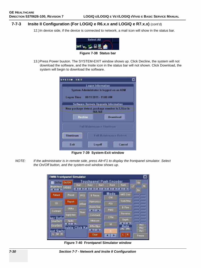
GE HEALTHCAREDIRECTION 5370626-100, REVISION 7 LOGIQ E/LOGIQ E VET/LOGIQ I/VIVID E BASIC SERVICE MANUAL
7-30 Section 7-7 - Network and Insite II Configuration
7-7-3 Insite II Configuration (For LOGIQ e R6.x.x and LOGIQ e R7.x.x) (cont’d)
12.)In device side, if the device is connected to network, a mail icon will show in the status bar.
13.)Press Power buuton. The SYSTEM-EXIT window shows up. Click Decline, the system will not download the software, and the Insite icon in the status bar will not shown. Click Download, the system will begin to download the software.
NOTE: If the administrator is in remote side, press Alt+F1 to display the frontpanel simulator. Select the On/Off button, and the system-exit window shows up.
Figure 7-38 Status bar
Figure 7-39 System-Exit window
Figure 7-40 Frontpanel Simulator window
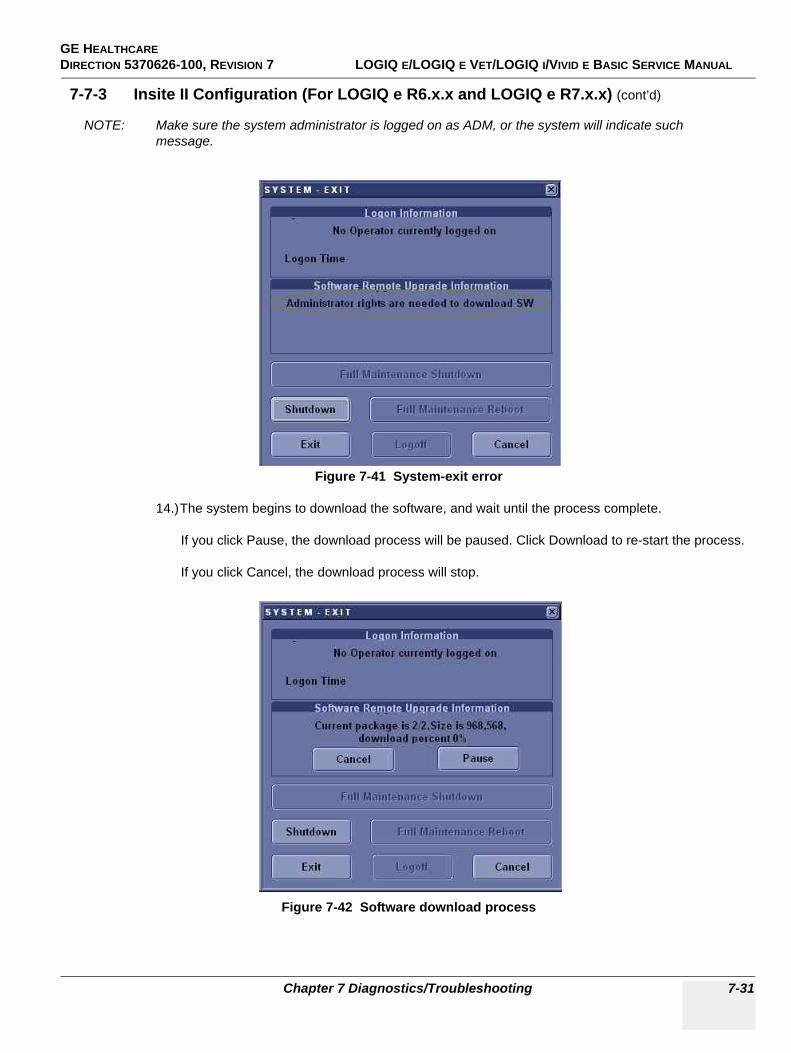
GE HEALTHCARE DIRECTION 5370626-100, REVISION 7 LOGIQ E/LOGIQ E VET/LOGIQ I/VIVID E BASIC SERVICE MANUAL
Chapter 7 Diagnostics/Troubleshooting 7-31
7-7-3 Insite II Configuration (For LOGIQ e R6.x.x and LOGIQ e R7.x.x) (cont’d)
NOTE: Make sure the system administrator is logged on as ADM, or the system will indicate such message.
14.)The system begins to download the software, and wait until the process complete.
If you click Pause, the download process will be paused. Click Download to re-start the process.
If you click Cancel, the download process will stop.
Figure 7-41 System-exit error
Figure 7-42 Software download process
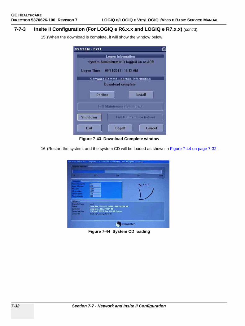
GE HEALTHCAREDIRECTION 5370626-100, REVISION 7 LOGIQ E/LOGIQ E VET/LOGIQ I/VIVID E BASIC SERVICE MANUAL
7-32 Section 7-7 - Network and Insite II Configuration
7-7-3 Insite II Configuration (For LOGIQ e R6.x.x and LOGIQ e R7.x.x) (cont’d)
15.)When the download is complete, it will show the window below.
16.)Restart the system, and the system CD will be loaded as shown in Figure 7-44 on page 7-32 .
Figure 7-43 Download Complete window
Figure 7-44 System CD loading
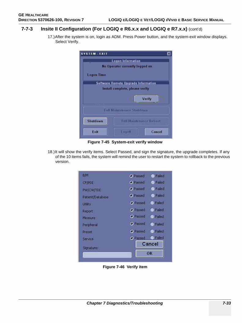
GE HEALTHCARE DIRECTION 5370626-100, REVISION 7 LOGIQ E/LOGIQ E VET/LOGIQ I/VIVID E BASIC SERVICE MANUAL
Chapter 7 Diagnostics/Troubleshooting 7-33
7-7-3 Insite II Configuration (For LOGIQ e R6.x.x and LOGIQ e R7.x.x) (cont’d)
17.)After the system is on, login as ADM. Press Power button, and the system-exit window displays. Select Verify.
18.)It will show the verify items. Select Passed, and sign the signature, the upgrade completes. If any of the 10 items fails, the system will remind the user to restart the system to rollback to the previous version.
Figure 7-45 System-exit verify window
Figure 7-46 Verify item
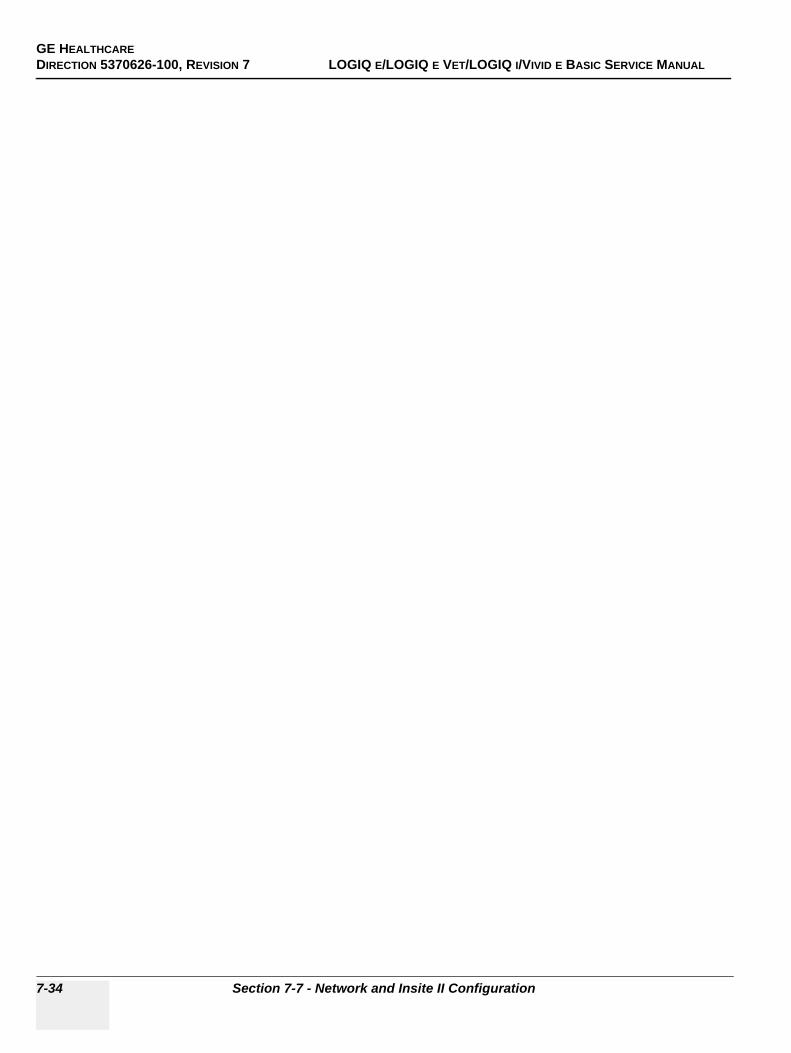
GE HEALTHCAREDIRECTION 5370626-100, REVISION 7 LOGIQ E/LOGIQ E VET/LOGIQ I/VIVID E BASIC SERVICE MANUAL
7-34 Section 7-7 - Network and Insite II Configuration
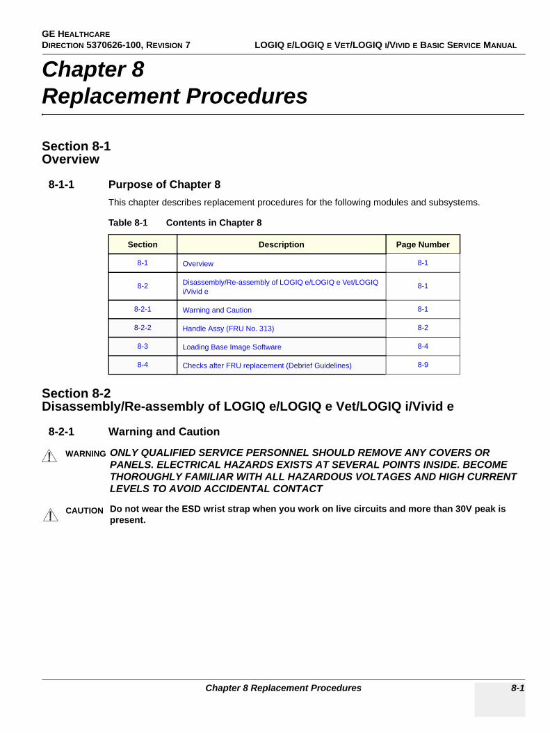
GE HEALTHCARE DIRECTION 5370626-100, REVISION 7 LOGIQ E/LOGIQ E VET/LOGIQ I/VIVID E BASIC SERVICE MANUAL
Chapter 8 Replacement Procedures 8-1
Chapter 8Replacement Procedures
Section 8-1Overview
8-1-1 Purpose of Chapter 8This chapter describes replacement procedures for the following modules and subsystems.
Section 8-2Disassembly/Re-assembly of LOGIQ e/LOGIQ e Vet/LOGIQ i/Vivid e
8-2-1 Warning and Caution
Table 8-1 Contents in Chapter 8
Section Description Page Number
8-1 Overview 8-1
8-2 Disassembly/Re-assembly of LOGIQ e/LOGIQ e Vet/LOGIQ i/Vivid e
8-1
8-2-1 Warning and Caution 8-1
8-2-2 Handle Assy (FRU No. 313) 8-2
8-3 Loading Base Image Software 8-4
8-4 Checks after FRU replacement (Debrief Guidelines) 8-9
WARNINGWARNING ONLY QUALIFIED SERVICE PERSONNEL SHOULD REMOVE ANY COVERS OR PANELS. ELECTRICAL HAZARDS EXISTS AT SEVERAL POINTS INSIDE. BECOME THOROUGHLY FAMILIAR WITH ALL HAZARDOUS VOLTAGES AND HIGH CURRENT LEVELS TO AVOID ACCIDENTAL CONTACT
CAUTION Do not wear the ESD wrist strap when you work on live circuits and more than 30V peak is present.
GE HEALTHCAREDIRECTION 5370626-100, REVISION 7 LOGIQ E/LOGIQ E VET/LOGIQ I/VIVID E BASIC SERVICE MANUAL
8-2 Section 8-2 - Disassembly/Re-assembly of LOGIQ e/LOGIQ e Vet/LOGIQ i/Vivid e
8-2-2 Handle Assy (FRU No. 313)Purpose: This is a description on how to remove and replace the Handle Assy (FRU No.313).
8-2-2-1 Tools• Plier
8-2-2-2 Needed Manpower• 1 person, 2 minutes + travel
8-2-2-3 Preparations• Shut Down the System.
8-2-2-4 Removal ProcedureRefer to Figure 8-1 on page 8-3 .
1.) Unscrew the two handle caps on both sides of the system, the rotation direction is counterclockwise.
2.) Pull out the Handle.
8-2-2-5 Mounting procedure
1.) Install the new parts in the reverse order of removal.
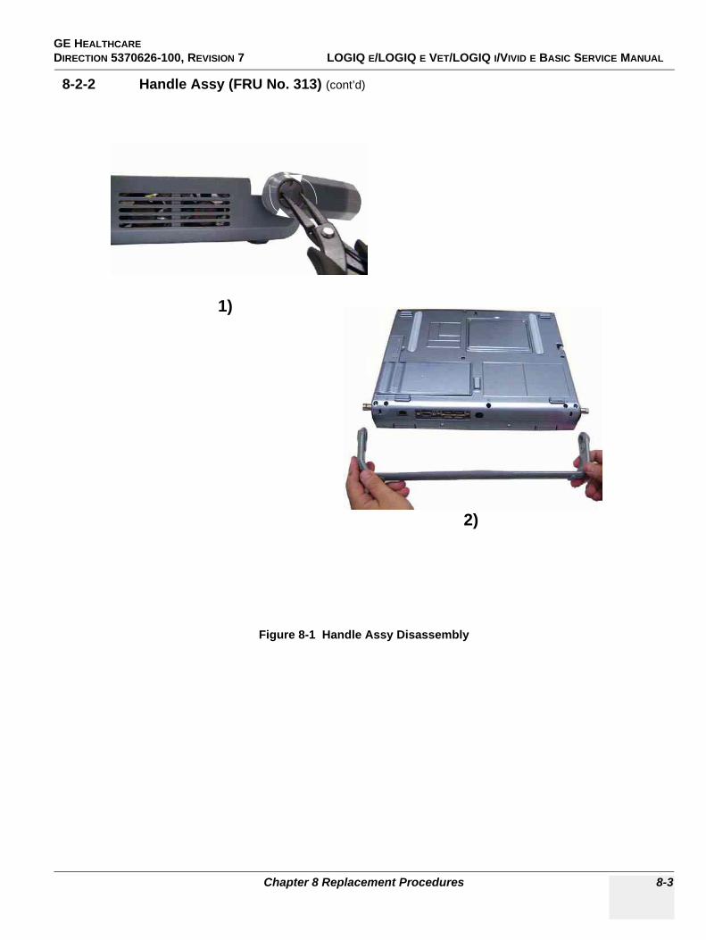
GE HEALTHCARE DIRECTION 5370626-100, REVISION 7 LOGIQ E/LOGIQ E VET/LOGIQ I/VIVID E BASIC SERVICE MANUAL
Chapter 8 Replacement Procedures 8-3
8-2-2 Handle Assy (FRU No. 313) (cont’d)
Figure 8-1 Handle Assy Disassembly
1)
2)
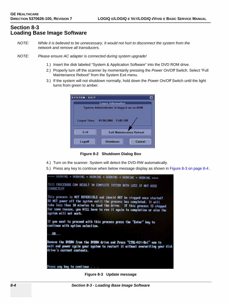
GE HEALTHCAREDIRECTION 5370626-100, REVISION 7 LOGIQ E/LOGIQ E VET/LOGIQ I/VIVID E BASIC SERVICE MANUAL
8-4 Section 8-3 - Loading Base Image Software
Section 8-3Loading Base Image Software
NOTE: While it is believed to be unnecessary, It would not hurt to disconnect the system from the network and remove all transducers.
NOTE: Please ensure AC adapter is connected during system upgrade!
1.) Insert the disk labeled “System & Application Software” into the DVD ROM drive.2.) Properly turn off the scanner by momentarily pressing the Power On/Off Switch. Select “Full
Maintenance Reboot” from the System Exit menu. 3.) If the system will not shutdown normally, hold down the Power On/Off Switch until the light
turns from green to amber.
4.) Turn on the scanner. System will detect the DVD-RW automatically.5.) Press any key to continue when below message display as shown in Figure 8-3 on page 8-4 .
Figure 8-2 Shutdown Dialog Box
Figure 8-3 Update message
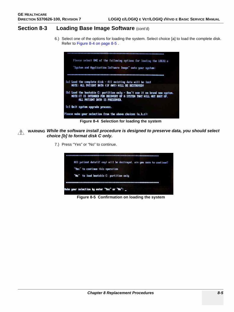
GE HEALTHCARE DIRECTION 5370626-100, REVISION 7 LOGIQ E/LOGIQ E VET/LOGIQ I/VIVID E BASIC SERVICE MANUAL
Chapter 8 Replacement Procedures 8-5
Section 8-3 Loading Base Image Software (cont’d)
6.) Select one of the options for loading the system. Select choice [a] to load the complete disk. Refer to Figure 8-4 on page 8-5 .
7.) Press “Yes” or “No” to continue.
Figure 8-4 Selection for loading the system
WARNINGWARNING While the software install procedure is designed to preserve data, you should select choice [b] to format disk C only.
Figure 8-5 Confirmation on loading the system
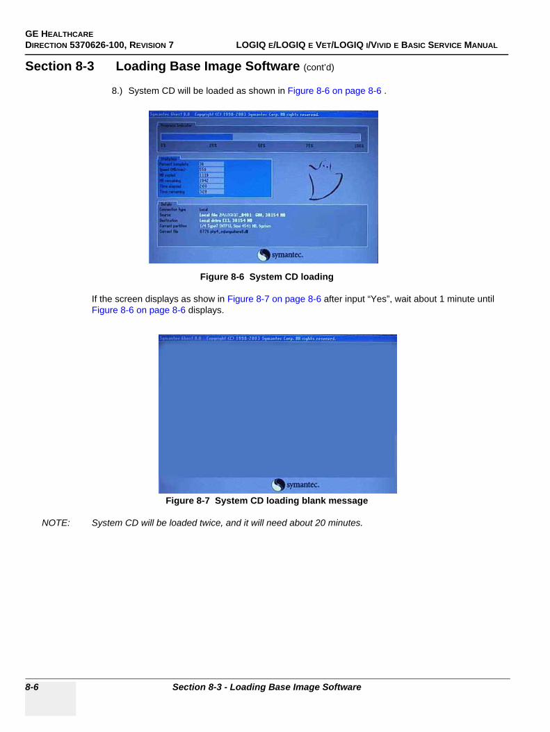
GE HEALTHCAREDIRECTION 5370626-100, REVISION 7 LOGIQ E/LOGIQ E VET/LOGIQ I/VIVID E BASIC SERVICE MANUAL
8-6 Section 8-3 - Loading Base Image Software
Section 8-3 Loading Base Image Software (cont’d)
8.) System CD will be loaded as shown in Figure 8-6 on page 8-6 .
If the screen displays as show in Figure 8-7 on page 8-6 after input “Yes”, wait about 1 minute until Figure 8-6 on page 8-6 displays.
NOTE: System CD will be loaded twice, and it will need about 20 minutes.
Figure 8-6 System CD loading
Figure 8-7 System CD loading blank message
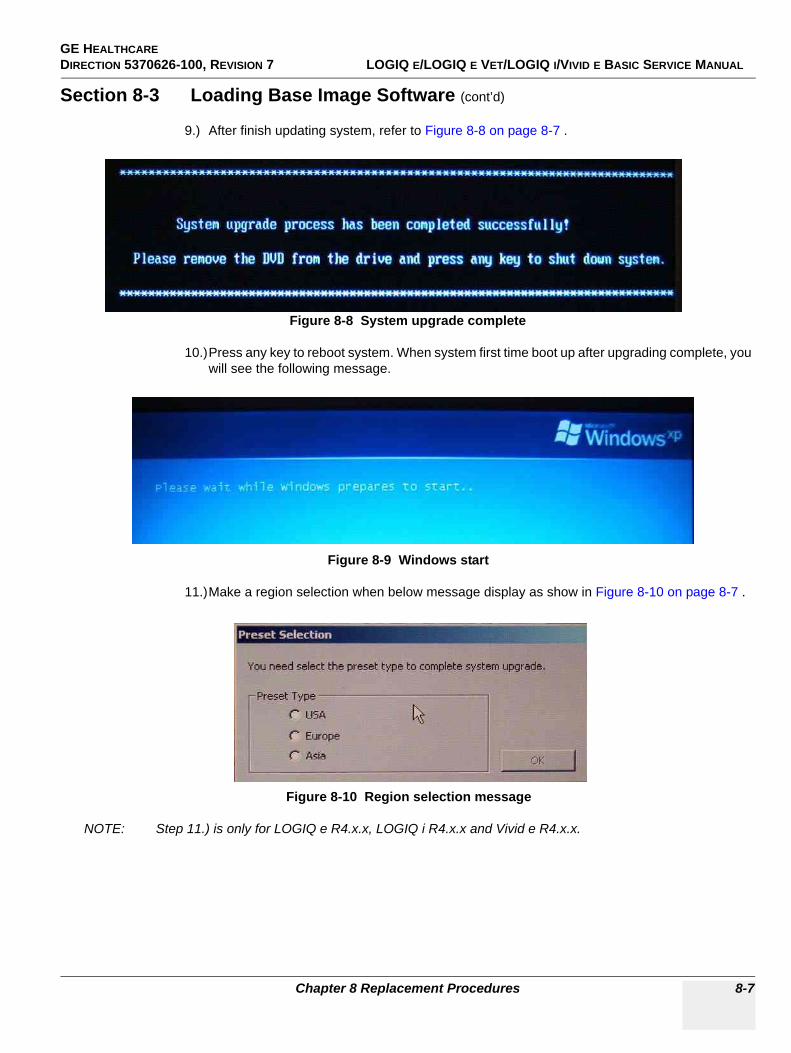
GE HEALTHCARE DIRECTION 5370626-100, REVISION 7 LOGIQ E/LOGIQ E VET/LOGIQ I/VIVID E BASIC SERVICE MANUAL
Chapter 8 Replacement Procedures 8-7
Section 8-3 Loading Base Image Software (cont’d)
9.) After finish updating system, refer to Figure 8-8 on page 8-7 .
10.)Press any key to reboot system. When system first time boot up after upgrading complete, you will see the following message.
11.)Make a region selection when below message display as show in Figure 8-10 on page 8-7 .
NOTE: Step 11.) is only for LOGIQ e R4.x.x, LOGIQ i R4.x.x and Vivid e R4.x.x.
Figure 8-8 System upgrade complete
Figure 8-9 Windows start
Figure 8-10 Region selection message
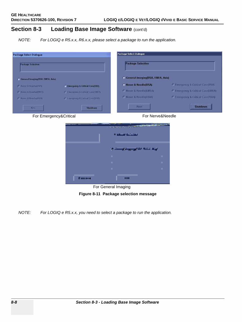
GE HEALTHCAREDIRECTION 5370626-100, REVISION 7 LOGIQ E/LOGIQ E VET/LOGIQ I/VIVID E BASIC SERVICE MANUAL
8-8 Section 8-3 - Loading Base Image Software
Section 8-3 Loading Base Image Software (cont’d)
NOTE: For LOGIQ e R5.x.x, R6.x.x, please select a package to run the application.
NOTE: For LOGIQ e R5.x.x, you need to select a package to run the application.
Figure 8-11 Package selection message
For Emergency&Critical For Nerve&Needle
For General Imaging
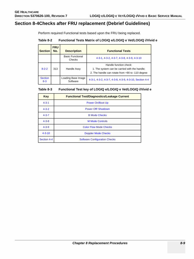
GE HEALTHCARE DIRECTION 5370626-100, REVISION 7 LOGIQ E/LOGIQ E VET/LOGIQ I/VIVID E BASIC SERVICE MANUAL
Chapter 8 Replacement Procedures 8-9
Section 8-4Checks after FRU replacement (Debrief Guidelines)
Perform required Functional tests based upon the FRU being replaced.
Table 8-2 Functional Tests Matrix of LOGIQ e/LOGIQ e Vet/LOGIQ i/Vivid e
SectionFRU No. Description Functional Tests
Basic Functional Checks 4-3-1, 4-3-2, 4-3-7, 4-3-8, 4-3-9, 4-3-10
8-2-2 313 Handle AssyHandle function check:
1. The system can be carried with the handle;2. The handle can rotate from +90 to -110 degree
Section 8-3
Loading Base Image Software 4-3-1, 4-3-2, 4-3-7, 4-3-8, 4-3-9, 4-3-10, Section 4-4
Table 8-3 Functional Test key of LOGIQ e/LOGIQ e Vet/LOGIQ i/Vivid e
Key Functional Test/Diagnostics/Leakage Current
4-3-1 Power On/Boot Up
4-3-2 Power Off/ Shutdown
4-3-7 B Mode Checks
4-3-8 M Mode Controls
4-3-9 Color Flow Mode Checks
4-3-10 Doppler Mode Checks
Section 4-4 Software Configuration Checks
GE HEALTHCAREDIRECTION 5370626-100, REVISION 7 LOGIQ E/LOGIQ E VET/LOGIQ I/VIVID E BASIC SERVICE MANUAL
8-10 Section 8-4 - Checks after FRU replacement (Debrief Guidelines)
This page was intentionally left blank.
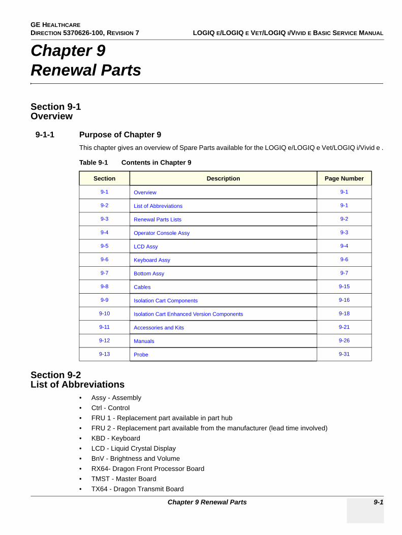
GE HEALTHCARE DIRECTION 5370626-100, REVISION 7 LOGIQ E/LOGIQ E VET/LOGIQ I/VIVID E BASIC SERVICE MANUAL
Chapter 9 Renewal Parts 9-1
Chapter 9Renewal Parts
Section 9-1Overview
9-1-1 Purpose of Chapter 9This chapter gives an overview of Spare Parts available for the LOGIQ e/LOGIQ e Vet/LOGIQ i/Vivid e .
Section 9-2List of Abbreviations
• Assy - Assembly• Ctrl - Control• FRU 1 - Replacement part available in part hub• FRU 2 - Replacement part available from the manufacturer (lead time involved)• KBD - Keyboard• LCD - Liquid Crystal Display• BnV - Brightness and Volume• RX64- Dragon Front Processor Board• TMST - Master Board• TX64 - Dragon Transmit Board
Table 9-1 Contents in Chapter 9
Section Description Page Number
9-1 Overview 9-1
9-2 List of Abbreviations 9-1
9-3 Renewal Parts Lists 9-2
9-4 Operator Console Assy 9-3
9-5 LCD Assy 9-4
9-6 Keyboard Assy 9-6
9-7 Bottom Assy 9-7
9-8 Cables 9-15
9-9 Isolation Cart Components 9-16
9-10 Isolation Cart Enhanced Version Components 9-18
9-11 Accessories and Kits 9-21
9-12 Manuals 9-26
9-13 Probe 9-31
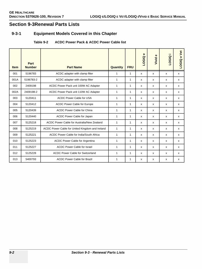
GE HEALTHCAREDIRECTION 5370626-100, REVISION 7 LOGIQ E/LOGIQ E VET/LOGIQ I/VIVID E BASIC SERVICE MANUAL
9-2 Section 9-3 - Renewal Parts Lists
Section 9-3Renewal Parts Lists
9-3-1 Equipment Models Covered in this Chapter
Table 9-2 ACDC Power Pack & ACDC Power Cable list
ItemPart
Number Part Name Quantity FRU
LOG
IQ e
Vivi
d e
LOG
IQ i
LOG
IQ e
Vet
001 5196783 ACDC adapter with clamp filter 1 1 x x x x
001A 5196783-2 ACDC adapter with clamp filter 1 1 x x x x
002 2409198 ACDC Power Pack unit 100W AC Adapter 1 1 x x x x
002A 2409198-2 ACDC Power Pack unit 110W AC Adapter 1 1 x x x x
003 5120411 ACDC Power Cable for USA 1 1 x x x x
004 5120412 ACDC Power Cable for Europe 1 1 x x x x
005 5120439 ACDC Power Cable for China 1 1 x x x x
006 5120440 ACDC Power Cable for Japan 1 1 x x x x
007 5125218 ACDC Power Cable for Australia/New Zealand 1 1 x x x x
008 5125219 ACDC Power Cable for United Kingdom and Ireland 1 1 x x x x
009 5125221 ACDC Power Cable for India/South Africa 1 1 x x x x
010 5125223 ACDC Power Cable for Argentina 1 1 x x x x
011 5125227 ACDC Power Cable for Israel 1 1 x x x x
012 5125228 ACDC Power Cable for Switzerland 1 1 x x x x
013 5400793 ACDC Power Cable for Brazil 1 1 x x x x
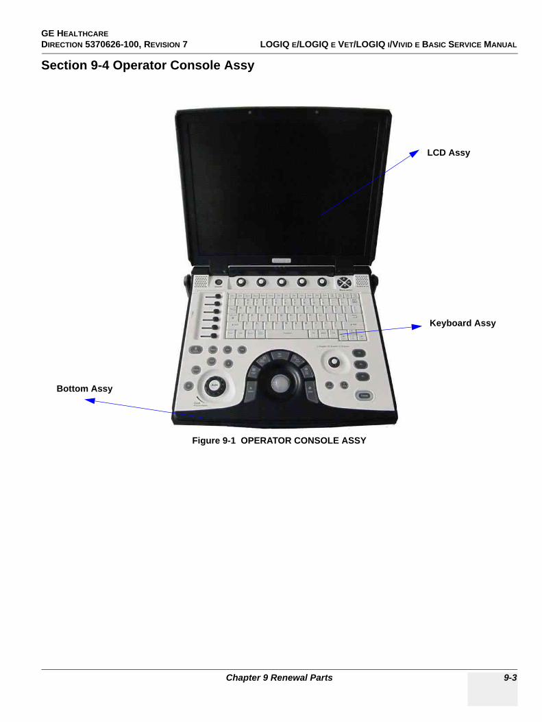
GE HEALTHCARE DIRECTION 5370626-100, REVISION 7 LOGIQ E/LOGIQ E VET/LOGIQ I/VIVID E BASIC SERVICE MANUAL
Chapter 9 Renewal Parts 9-3
Section 9-4 Operator Console Assy
Figure 9-1 OPERATOR CONSOLE ASSY
LCD Assy
Keyboard Assy
Bottom Assy
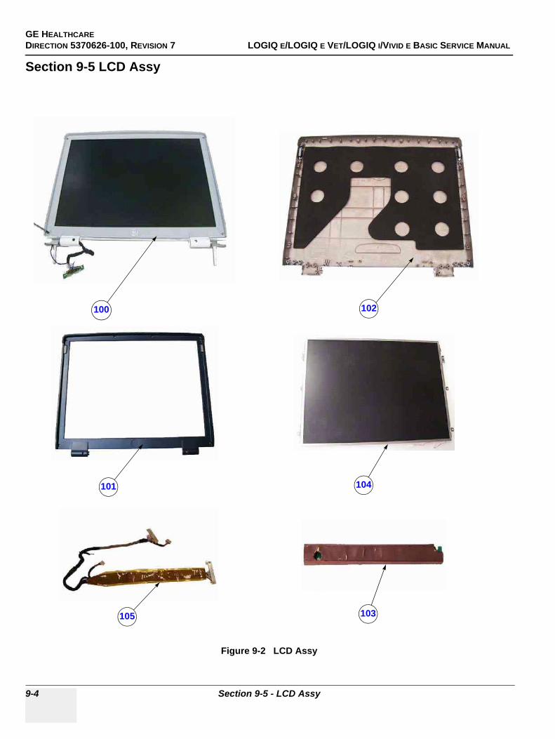
GE HEALTHCAREDIRECTION 5370626-100, REVISION 7 LOGIQ E/LOGIQ E VET/LOGIQ I/VIVID E BASIC SERVICE MANUAL
9-4 Section 9-5 - LCD Assy
Section 9-5 LCD Assy
Figure 9-2 LCD Assy
100
101
102
103
104
105
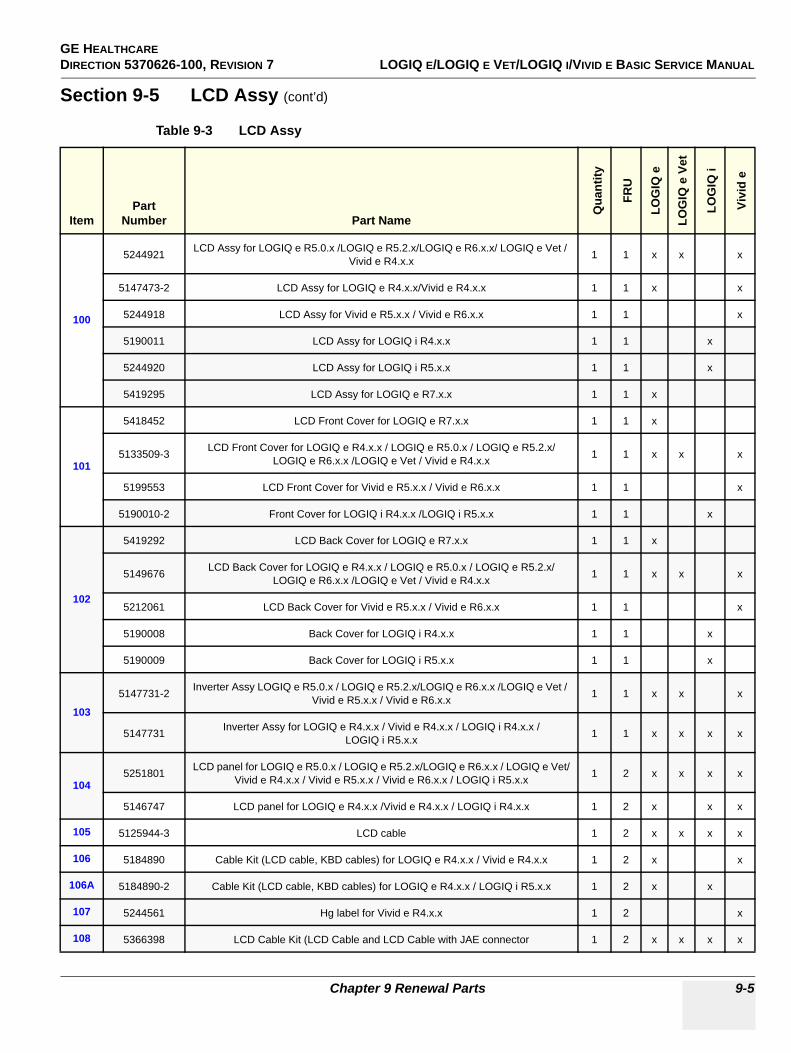
GE HEALTHCARE DIRECTION 5370626-100, REVISION 7 LOGIQ E/LOGIQ E VET/LOGIQ I/VIVID E BASIC SERVICE MANUAL
Chapter 9 Renewal Parts 9-5
Section 9-5 LCD Assy (cont’d)
Table 9-3 LCD Assy
ItemPart
Number Part Name
Qua
ntity
FRU
LOG
IQ e
LOG
IQ e
Vet
LOG
IQ i
Vivi
d e
100
5244921 LCD Assy for LOGIQ e R5.0.x /LOGIQ e R5.2.x/LOGIQ e R6.x.x/ LOGIQ e Vet / Vivid e R4.x.x 1 1 x x x
5147473-2 LCD Assy for LOGIQ e R4.x.x/Vivid e R4.x.x 1 1 x x
5244918 LCD Assy for Vivid e R5.x.x / Vivid e R6.x.x 1 1 x
5190011 LCD Assy for LOGIQ i R4.x.x 1 1 x
5244920 LCD Assy for LOGIQ i R5.x.x 1 1 x
5419295 LCD Assy for LOGIQ e R7.x.x 1 1 x
101
5418452 LCD Front Cover for LOGIQ e R7.x.x 1 1 x
5133509-3 LCD Front Cover for LOGIQ e R4.x.x / LOGIQ e R5.0.x / LOGIQ e R5.2.x/LOGIQ e R6.x.x /LOGIQ e Vet / Vivid e R4.x.x 1 1 x x x
5199553 LCD Front Cover for Vivid e R5.x.x / Vivid e R6.x.x 1 1 x
5190010-2 Front Cover for LOGIQ i R4.x.x /LOGIQ i R5.x.x 1 1 x
102
5419292 LCD Back Cover for LOGIQ e R7.x.x 1 1 x
5149676 LCD Back Cover for LOGIQ e R4.x.x / LOGIQ e R5.0.x / LOGIQ e R5.2.x/LOGIQ e R6.x.x /LOGIQ e Vet / Vivid e R4.x.x 1 1 x x x
5212061 LCD Back Cover for Vivid e R5.x.x / Vivid e R6.x.x 1 1 x
5190008 Back Cover for LOGIQ i R4.x.x 1 1 x
5190009 Back Cover for LOGIQ i R5.x.x 1 1 x
103
5147731-2 Inverter Assy LOGIQ e R5.0.x / LOGIQ e R5.2.x/LOGIQ e R6.x.x /LOGIQ e Vet / Vivid e R5.x.x / Vivid e R6.x.x 1 1 x x x
5147731 Inverter Assy for LOGIQ e R4.x.x / Vivid e R4.x.x / LOGIQ i R4.x.x / LOGIQ i R5.x.x 1 1 x x x x
1045251801 LCD panel for LOGIQ e R5.0.x / LOGIQ e R5.2.x/LOGIQ e R6.x.x / LOGIQ e Vet/
Vivid e R4.x.x / Vivid e R5.x.x / Vivid e R6.x.x / LOGIQ i R5.x.x 1 2 x x x x
5146747 LCD panel for LOGIQ e R4.x.x /Vivid e R4.x.x / LOGIQ i R4.x.x 1 2 x x x
105 5125944-3 LCD cable 1 2 x x x x
106 5184890 Cable Kit (LCD cable, KBD cables) for LOGIQ e R4.x.x / Vivid e R4.x.x 1 2 x x
106A 5184890-2 Cable Kit (LCD cable, KBD cables) for LOGIQ e R4.x.x / LOGIQ i R5.x.x 1 2 x x
107 5244561 Hg label for Vivid e R4.x.x 1 2 x
108 5366398 LCD Cable Kit (LCD Cable and LCD Cable with JAE connector 1 2 x x x x
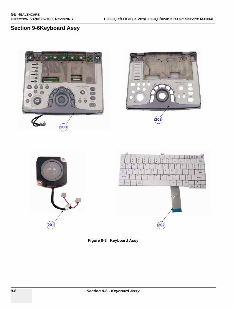
GE HEALTHCAREDIRECTION 5370626-100, REVISION 7 LOGIQ E/LOGIQ E VET/LOGIQ I/VIVID E BASIC SERVICE MANUAL
9-6 Section 9-6 - Keyboard Assy
Section 9-6Keyboard Assy
Figure 9-3 Keyboard Assy
200
201 202
203
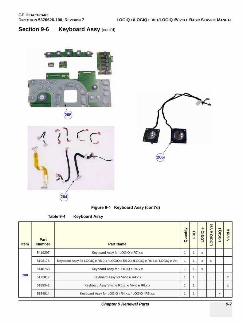
GE HEALTHCARE DIRECTION 5370626-100, REVISION 7 LOGIQ E/LOGIQ E VET/LOGIQ I/VIVID E BASIC SERVICE MANUAL
Chapter 9 Renewal Parts 9-7
Section 9-6 Keyboard Assy (cont’d)
Figure 9-4 Keyboard Assy (cont’d)
Table 9-4 Keyboard Assy
ItemPart
Number Part Name
Qua
ntity
FRU
LOG
IQ e
LOG
IQ e
Vet
LOG
IQ i
Vivi
d e
200
5419297 Keyboard Assy for LOGIQ e R7.x.x 1 1 x
5198176 Keyboard Assy for LOGIQ e R5.0.x / LOGIQ e R5.2.x /LOGIQ e R6.x.x / LOGIQ e Vet 1 1 x x
5148753 Keyboard Assy for LOGIQ e R4.x.x 1 1 x
5172817 Keyboard Assy for Vivid e R4.x.x 1 1 x
5199342 Keyboard Assy Vivid e R5.x. x/ Vivid e R6.x.x 1 1 x
5184814 Keyboard Assy for LOGIQ i R4.x.x / LOGIQ i R5.x.x 1 1 x
205
204
206
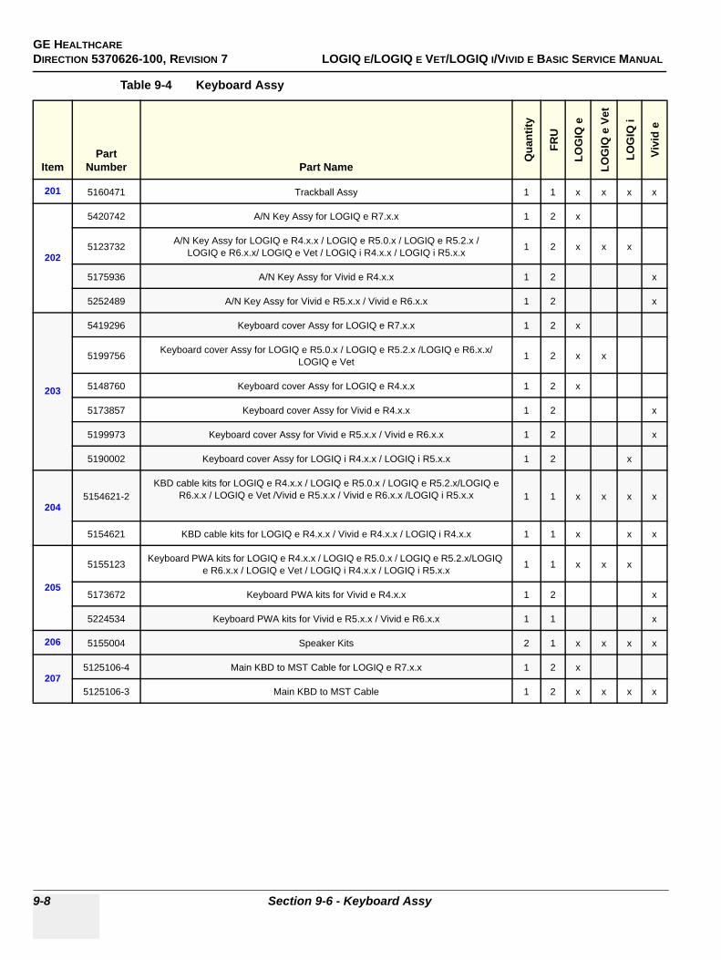
GE HEALTHCAREDIRECTION 5370626-100, REVISION 7 LOGIQ E/LOGIQ E VET/LOGIQ I/VIVID E BASIC SERVICE MANUAL
9-8 Section 9-6 - Keyboard Assy
201 5160471 Trackball Assy 1 1 x x x x
202
5420742 A/N Key Assy for LOGIQ e R7.x.x 1 2 x
5123732 A/N Key Assy for LOGIQ e R4.x.x / LOGIQ e R5.0.x / LOGIQ e R5.2.x /LOGIQ e R6.x.x/ LOGIQ e Vet / LOGIQ i R4.x.x / LOGIQ i R5.x.x 1 2 x x x
5175936 A/N Key Assy for Vivid e R4.x.x 1 2 x
5252489 A/N Key Assy for Vivid e R5.x.x / Vivid e R6.x.x 1 2 x
203
5419296 Keyboard cover Assy for LOGIQ e R7.x.x 1 2 x
5199756 Keyboard cover Assy for LOGIQ e R5.0.x / LOGIQ e R5.2.x /LOGIQ e R6.x.x/ LOGIQ e Vet 1 2 x x
5148760 Keyboard cover Assy for LOGIQ e R4.x.x 1 2 x
5173857 Keyboard cover Assy for Vivid e R4.x.x 1 2 x
5199973 Keyboard cover Assy for Vivid e R5.x.x / Vivid e R6.x.x 1 2 x
5190002 Keyboard cover Assy for LOGIQ i R4.x.x / LOGIQ i R5.x.x 1 2 x
2045154621-2
KBD cable kits for LOGIQ e R4.x.x / LOGIQ e R5.0.x / LOGIQ e R5.2.x/LOGIQ e R6.x.x / LOGIQ e Vet /Vivid e R5.x.x / Vivid e R6.x.x /LOGIQ i R5.x.x 1 1 x x x x
5154621 KBD cable kits for LOGIQ e R4.x.x / Vivid e R4.x.x / LOGIQ i R4.x.x 1 1 x x x
205
5155123 Keyboard PWA kits for LOGIQ e R4.x.x / LOGIQ e R5.0.x / LOGIQ e R5.2.x/LOGIQ e R6.x.x / LOGIQ e Vet / LOGIQ i R4.x.x / LOGIQ i R5.x.x 1 1 x x x
5173672 Keyboard PWA kits for Vivid e R4.x.x 1 2 x
5224534 Keyboard PWA kits for Vivid e R5.x.x / Vivid e R6.x.x 1 1 x
206 5155004 Speaker Kits 2 1 x x x x
2075125106-4 Main KBD to MST Cable for LOGIQ e R7.x.x 1 2 x
5125106-3 Main KBD to MST Cable 1 2 x x x x
Table 9-4 Keyboard Assy
ItemPart
Number Part Name
Qua
ntity
FRU
LOG
IQ e
LOG
IQ e
Vet
LOG
IQ i
Vivi
d e
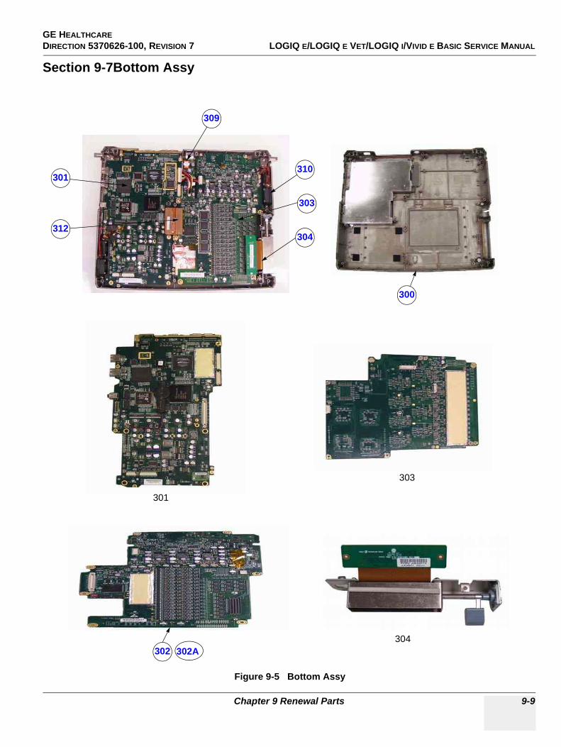
GE HEALTHCARE DIRECTION 5370626-100, REVISION 7 LOGIQ E/LOGIQ E VET/LOGIQ I/VIVID E BASIC SERVICE MANUAL
Chapter 9 Renewal Parts 9-9
Section 9-7Bottom Assy
Figure 9-5 Bottom Assy
300
301
302
303
304
310
312
301
303
309
304302A
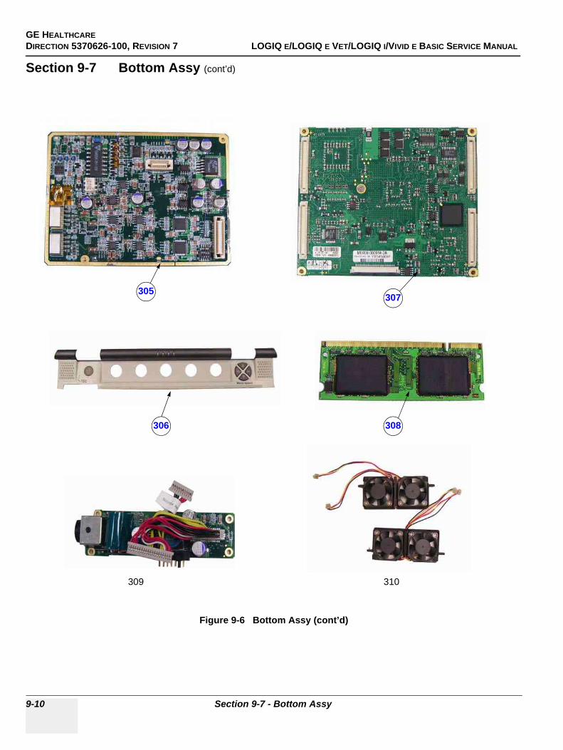
GE HEALTHCAREDIRECTION 5370626-100, REVISION 7 LOGIQ E/LOGIQ E VET/LOGIQ I/VIVID E BASIC SERVICE MANUAL
9-10 Section 9-7 - Bottom Assy
Section 9-7 Bottom Assy (cont’d)
Figure 9-6 Bottom Assy (cont’d)
307
308
310309
306
305
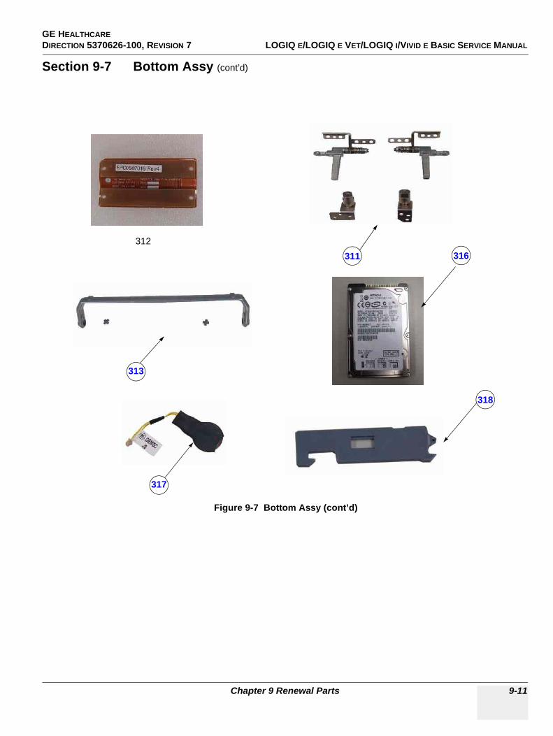
GE HEALTHCARE DIRECTION 5370626-100, REVISION 7 LOGIQ E/LOGIQ E VET/LOGIQ I/VIVID E BASIC SERVICE MANUAL
Chapter 9 Renewal Parts 9-11
Section 9-7 Bottom Assy (cont’d)
Figure 9-7 Bottom Assy (cont’d)
313
317
316311312
318
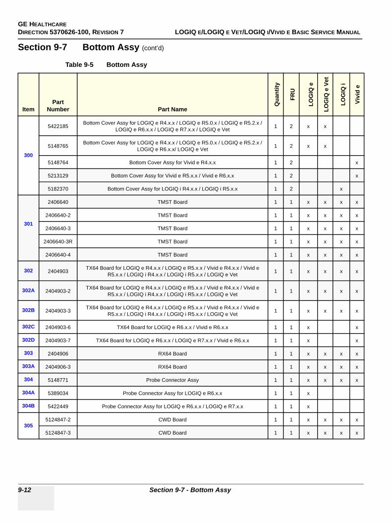
GE HEALTHCAREDIRECTION 5370626-100, REVISION 7 LOGIQ E/LOGIQ E VET/LOGIQ I/VIVID E BASIC SERVICE MANUAL
9-12 Section 9-7 - Bottom Assy
Section 9-7 Bottom Assy (cont’d)
Table 9-5 Bottom Assy
ItemPart
Number Part Name
Qua
ntity
FRU
LOG
IQ e
LOG
IQ e
Vet
LOG
IQ i
Vivi
d e
300
5422185 Bottom Cover Assy for LOGIQ e R4.x.x / LOGIQ e R5.0.x / LOGIQ e R5.2.x /LOGIQ e R6.x.x / LOGIQ e R7.x.x / LOGIQ e Vet 1 2 x x
5148765 Bottom Cover Assy for LOGIQ e R4.x.x / LOGIQ e R5.0.x / LOGIQ e R5.2.x /LOGIQ e R6.x.x/ LOGIQ e Vet 1 2 x x
5148764 Bottom Cover Assy for Vivid e R4.x.x 1 2 x
5213129 Bottom Cover Assy for Vivid e R5.x.x / Vivid e R6.x.x 1 2 x
5182370 Bottom Cover Assy for LOGIQ i R4.x.x / LOGIQ i R5.x.x 1 2 x
301
2406640 TMST Board 1 1 x x x x
2406640-2 TMST Board 1 1 x x x x
2406640-3 TMST Board 1 1 x x x x
2406640-3R TMST Board 1 1 x x x x
2406640-4 TMST Board 1 1 x x x x
302 2404903 TX64 Board for LOGIQ e R4.x.x / LOGIQ e R5.x.x / Vivid e R4.x.x / Vivid e R5.x.x / LOGIQ i R4.x.x / LOGIQ i R5.x.x / LOGIQ e Vet 1 1 x x x x
302A 2404903-2 TX64 Board for LOGIQ e R4.x.x / LOGIQ e R5.x.x / Vivid e R4.x.x / Vivid e R5.x.x / LOGIQ i R4.x.x / LOGIQ i R5.x.x / LOGIQ e Vet 1 1 x x x x
302B 2404903-3 TX64 Board for LOGIQ e R4.x.x / LOGIQ e R5.x.x / Vivid e R4.x.x / Vivid e R5.x.x / LOGIQ i R4.x.x / LOGIQ i R5.x.x / LOGIQ e Vet 1 1 x x x x
302C 2404903-6 TX64 Board for LOGIQ e R6.x.x / Vivid e R6.x.x 1 1 x x
302D 2404903-7 TX64 Board for LOGIQ e R6.x.x / LOGIQ e R7.x.x / Vivid e R6.x.x 1 1 x x
303 2404906 RX64 Board 1 1 x x x x
303A 2404906-3 RX64 Board 1 1 x x x x
304 5148771 Probe Connector Assy 1 1 x x x x
304A 5389034 Probe Connector Assy for LOGIQ e R6.x.x 1 1 x
304B 5422449 Probe Connector Assy for LOGIQ e R6.x.x / LOGIQ e R7.x.x 1 1 x
3055124847-2 CWD Board 1 1 x x x x
5124847-3 CWD Board 1 1 x x x x
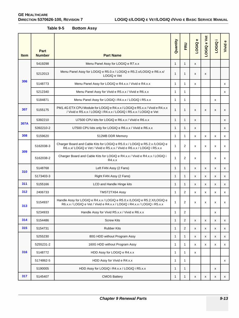
GE HEALTHCARE DIRECTION 5370626-100, REVISION 7 LOGIQ E/LOGIQ E VET/LOGIQ I/VIVID E BASIC SERVICE MANUAL
Chapter 9 Renewal Parts 9-13
306
5419298 Menu Panel Assy for LOGIQ e R7.x.x 1 1 x
5212013 Menu Panel Assy for LOGIQ e R5.0.x / LOGIQ e R5.2.x/LOGIQ e R6.x.x/ LOGIQ e Vet 1 1 x x
5148773 Menu Panel Assy for LOGIQ e R4.x.x / Vivid e R4.x.x 1 1 x x
5212340 Menu Panel Assy for Vivid e R5.x.x / Vivid e R6.x.x 1 1 x
5184871 Menu Panel Assy for LOGIQ i R4.x.x / LOGIQ i R5.x.x 1 1 x
307 5155175 PM1.4G ETX CPU Module for LOGIQ e R4.x.x / LOGIQ e R5.x.x / Vivid e R4.x.x / Vivid e R5.x.x / LOGIQ i R4.x.x / LOGIQ i R5.x.x / LOGIQ e Vet 1 1 x x x x
307A5392210 U7500 CPU kits for LOGIQ e R6.x.x / Vivid e R6.x.x 1 1 x x
5392210-2 U7500 CPU kits only for LOGIQ e R6.x.x / Vivid e R6.x.x 1 1 x x
308 5159620 512MB DDR Memory 1 1 x x x x
309
5162038-3 Charger Board and Cable Kits for LOGIQ e R5.0.x / LOGIQ e R5.2.x /LOGIQ e R6.x.x/ LOGIQ e Vet / Vivid e R5.x.x / Vivid e R6.x.x / LOGIQ i R5.x.x 1 2 x x x x
5162038-2 Charger Board and Cable Kits for LOGIQ e R4.x.x / Vivid e R4.x.x / LOGIQ i R4.x.x 1 2 x x x
3105148768 Left FAN Assy (2 Fans) 1 1 x x x x
5173403-3 Right FAN Assy (2 Fans) 1 1 x x x x
311 5155166 LCD and Handle Hinge kits 1 1 x x x x
312 2406733 TMST2TX64 Assy 1 2 x x x x
3135154937 Handle Assy for LOGIQ e R4.x.x / LOGIQ e R5.0.x /LOGIQ e R5.2.X/LOGIQ e
R6.x.x / LOGIQ e Vet / Vivid e R4.x.x / LOGIQ i R4.x.x / LOGIQ i R5.x.x 1 2 x x x x
5234933 Handle Assy for Vivid R5.x.x / Vivid e R6.x.x 1 2 x
314 5154486 Screw Kits 1 2 x x x x
315 5154731 Rubber Kits 1 2 x x x x
316
5255230 80G HDD without Program Assy 1 1 x x x x
5255231-2 160G HDD without Program Assy 1 1 x x x x
5148772 HDD Assy for LOGIQ e R4.x.x 1 1 x
5174862-5 HDD Assy for Vivid e R4.x.x 1 1 x
5190005 HDD Assy for LOGIQ i R4.x.x / LOGIQ i R5.x.x 1 1 x
317 5145407 CMOS Battery 1 1 x x x x
Table 9-5 Bottom Assy
ItemPart
Number Part Name
Qua
ntity
FRU
LOG
IQ e
LOG
IQ e
Vet
LOG
IQ i
Vivi
d e
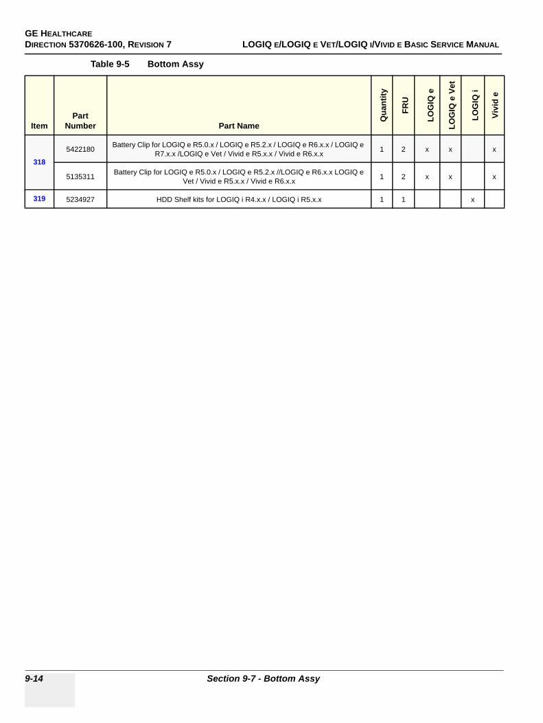
GE HEALTHCAREDIRECTION 5370626-100, REVISION 7 LOGIQ E/LOGIQ E VET/LOGIQ I/VIVID E BASIC SERVICE MANUAL
9-14 Section 9-7 - Bottom Assy
318
5422180 Battery Clip for LOGIQ e R5.0.x / LOGIQ e R5.2.x / LOGIQ e R6.x.x / LOGIQ e R7.x.x /LOGIQ e Vet / Vivid e R5.x.x / Vivid e R6.x.x 1 2 x x x
5135311 Battery Clip for LOGIQ e R5.0.x / LOGIQ e R5.2.x //LOGIQ e R6.x.x LOGIQ e Vet / Vivid e R5.x.x / Vivid e R6.x.x 1 2 x x x
319 5234927 HDD Shelf kits for LOGIQ i R4.x.x / LOGIQ i R5.x.x 1 1 x
Table 9-5 Bottom Assy
ItemPart
Number Part Name
Qua
ntity
FRU
LOG
IQ e
LOG
IQ e
Vet
LOG
IQ i
Vivi
d e
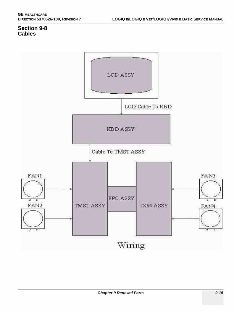
GE HEALTHCARE DIRECTION 5370626-100, REVISION 7 LOGIQ E/LOGIQ E VET/LOGIQ I/VIVID E BASIC SERVICE MANUAL
Chapter 9 Renewal Parts 9-15
Section 9-8Cables
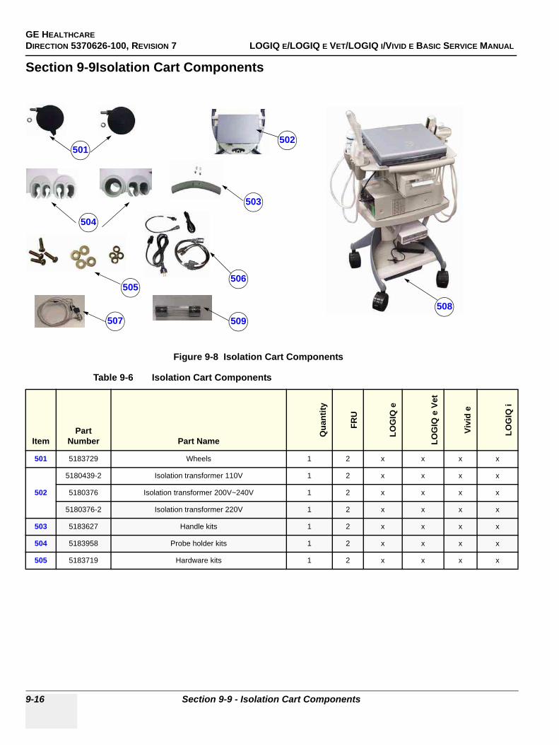
GE HEALTHCAREDIRECTION 5370626-100, REVISION 7 LOGIQ E/LOGIQ E VET/LOGIQ I/VIVID E BASIC SERVICE MANUAL
9-16 Section 9-9 - Isolation Cart Components
Section 9-9Isolation Cart Components
Figure 9-8 Isolation Cart Components
Table 9-6 Isolation Cart Components
ItemPart
Number Part Name
Qua
ntity
FRU
LOG
IQ e
LOG
IQ e
Vet
Vivi
d e
LOG
IQ i
501 5183729 Wheels 1 2 x x x x
502
5180439-2 Isolation transformer 110V 1 2 x x x x
5180376 Isolation transformer 200V~240V 1 2 x x x x
5180376-2 Isolation transformer 220V 1 2 x x x x
503 5183627 Handle kits 1 2 x x x x
504 5183958 Probe holder kits 1 2 x x x x
505 5183719 Hardware kits 1 2 x x x x
501
503
504
505506
507508
502
509
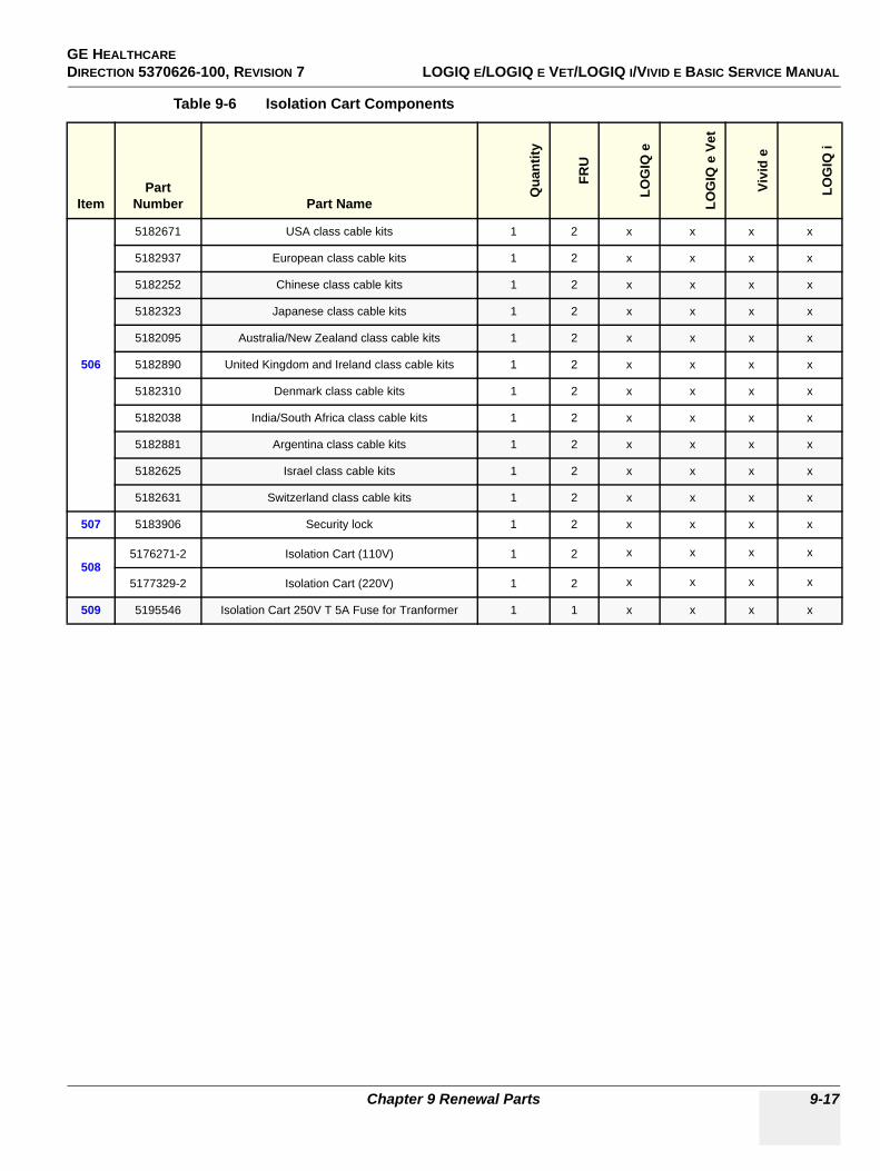
GE HEALTHCARE DIRECTION 5370626-100, REVISION 7 LOGIQ E/LOGIQ E VET/LOGIQ I/VIVID E BASIC SERVICE MANUAL
Chapter 9 Renewal Parts 9-17
506
5182671 USA class cable kits 1 2 x x x x
5182937 European class cable kits 1 2 x x x x
5182252 Chinese class cable kits 1 2 x x x x
5182323 Japanese class cable kits 1 2 x x x x
5182095 Australia/New Zealand class cable kits 1 2 x x x x
5182890 United Kingdom and Ireland class cable kits 1 2 x x x x
5182310 Denmark class cable kits 1 2 x x x x
5182038 India/South Africa class cable kits 1 2 x x x x
5182881 Argentina class cable kits 1 2 x x x x
5182625 Israel class cable kits 1 2 x x x x
5182631 Switzerland class cable kits 1 2 x x x x
507 5183906 Security lock 1 2 x x x x
5085176271-2 Isolation Cart (110V) 1 2 x x x x
5177329-2 Isolation Cart (220V) 1 2 x x x x
509 5195546 Isolation Cart 250V T 5A Fuse for Tranformer 1 1 x x x x
Table 9-6 Isolation Cart Components
ItemPart
Number Part Name
Qua
ntity
FRU
LOG
IQ e
LOG
IQ e
Vet
Vivi
d e
LOG
IQ i

GE HEALTHCAREDIRECTION 5370626-100, REVISION 7 LOGIQ E/LOGIQ E VET/LOGIQ I/VIVID E BASIC SERVICE MANUAL
9-18 Section 9-10 - Isolation Cart Enhanced Version Components
Section 9-10Isolation Cart Enhanced Version Components
Figure 9-9 Isolation Cart Components
515
511
513
514
516 517
518
512
519521
522
523
524
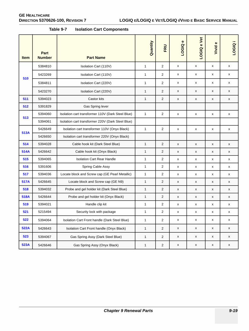
GE HEALTHCARE DIRECTION 5370626-100, REVISION 7 LOGIQ E/LOGIQ E VET/LOGIQ I/VIVID E BASIC SERVICE MANUAL
Chapter 9 Renewal Parts 9-19
Table 9-7 Isolation Cart Components
ItemPart
Number Part Name
Qua
ntity
FRU
LOG
IQ e
LOG
IQ e
Vet
Vivi
d e
LOG
IQ i
510
5384810 Isolation Cart (110V) 1 2 x x x x
5423269 Isolation Cart (110V) 1 2 x x x x
5384811 Isolation Cart (220V) 1 2 x x x x
5423270 Isolation Cart (220V) 1 2 x x x x
511 5394023 Castor kits 1 2 x x x x
512 5391829 Gas Spring lever
5135394060 Isolation cart transformer 110V (Dark Steel Blue) 1 2 x x x x
5394061 Isolation cart transformer 220V (Dark Steel Blue)
513A5426649 Isolation cart transformer 110V (Onyx Black) 1 2 x x x x
5426650 Isolation cart transformer 220V (Onyx Black)
514 5394028 Cable hook kit (Dark Steel Blue) 1 2 x x x x
514A 5426642 Cable hook kit (Onyx Black) 1 2 x x x x
515 5394065 Isolation Cart Rear Handle 1 2 x x x x
516 5391606 Spring Cable Assy 1 2 x x x x
517 5394036 Locate block and Screw cap (GE Pearl Metallic) 1 2 x x x x
517A 5426645 Locate block and Screw cap (GE N9) 1 2 x x x x
518 5394032 Probe and gel holder kit (Dark Steel Blue) 1 2 x x x x
518A 5426644 Probe and gel holder kit (Onyx Black) 1 2 x x x x
519 5394021 Handle clip kit 1 2 x x x x
521 5215494 Security lock with package 1 2 x x x x
522 5394064 Isolation Cart Front handle (Dark Steel Blue) 1 2 x x x x
522A 5426643 Isolation Cart Front handle (Onyx Black) 1 2 x x x x
523 5394067 Gas Spring Assy (Dark Steel Blue) 1 2 x x x x
523A 5426646 Gas Spring Assy (Onyx Black) 1 2 x x x x
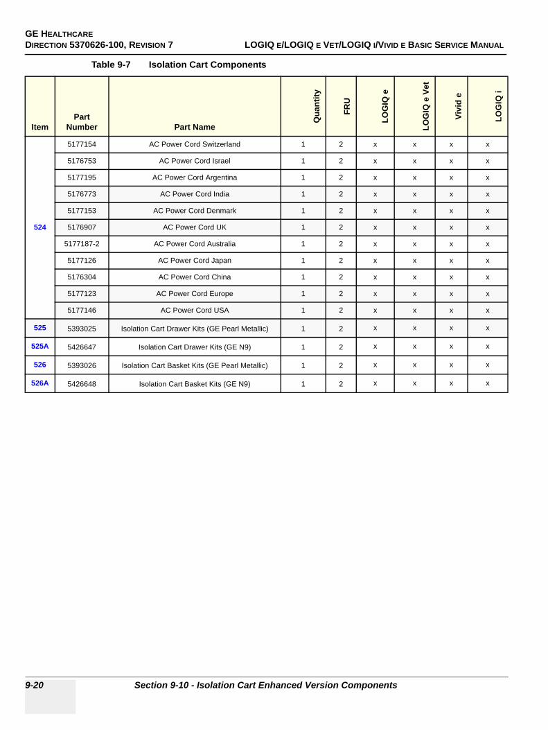
GE HEALTHCAREDIRECTION 5370626-100, REVISION 7 LOGIQ E/LOGIQ E VET/LOGIQ I/VIVID E BASIC SERVICE MANUAL
9-20 Section 9-10 - Isolation Cart Enhanced Version Components
524
5177154 AC Power Cord Switzerland 1 2 x x x x
5176753 AC Power Cord Israel 1 2 x x x x
5177195 AC Power Cord Argentina 1 2 x x x x
5176773 AC Power Cord India 1 2 x x x x
5177153 AC Power Cord Denmark 1 2 x x x x
5176907 AC Power Cord UK 1 2 x x x x
5177187-2 AC Power Cord Australia 1 2 x x x x
5177126 AC Power Cord Japan 1 2 x x x x
5176304 AC Power Cord China 1 2 x x x x
5177123 AC Power Cord Europe 1 2 x x x x
5177146 AC Power Cord USA 1 2 x x x x
525 5393025 Isolation Cart Drawer Kits (GE Pearl Metallic) 1 2 x x x x
525A 5426647 Isolation Cart Drawer Kits (GE N9) 1 2 x x x x
526 5393026 Isolation Cart Basket Kits (GE Pearl Metallic) 1 2 x x x x
526A 5426648 Isolation Cart Basket Kits (GE N9) 1 2 x x x x
Table 9-7 Isolation Cart Components
ItemPart
Number Part Name
Qua
ntity
FRU
LOG
IQ e
LOG
IQ e
Vet
Vivi
d e
LOG
IQ i
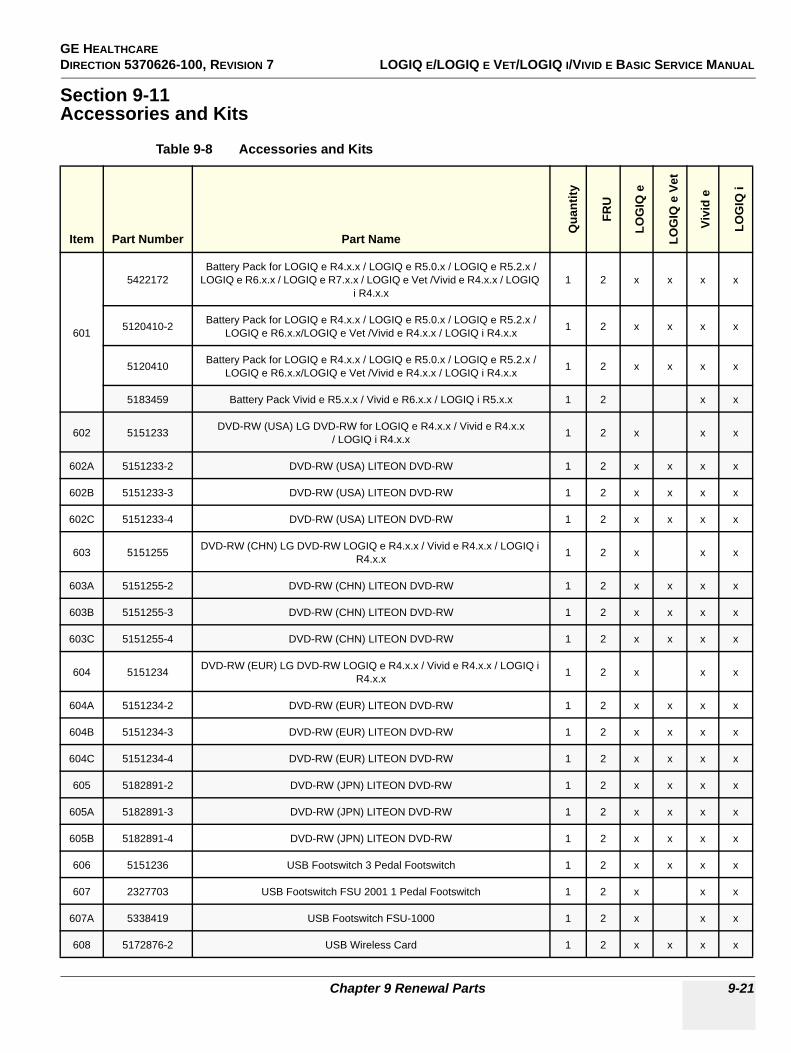
GE HEALTHCARE DIRECTION 5370626-100, REVISION 7 LOGIQ E/LOGIQ E VET/LOGIQ I/VIVID E BASIC SERVICE MANUAL
Chapter 9 Renewal Parts 9-21
Section 9-11Accessories and Kits
Table 9-8 Accessories and Kits
Item Part Number Part Name
Qua
ntity
FRU
LOG
IQ e
LOG
IQ e
Vet
Vivi
d e
LOG
IQ i
601
5422172Battery Pack for LOGIQ e R4.x.x / LOGIQ e R5.0.x / LOGIQ e R5.2.x /
LOGIQ e R6.x.x / LOGIQ e R7.x.x / LOGIQ e Vet /Vivid e R4.x.x / LOGIQ i R4.x.x
1 2 x x x x
5120410-2 Battery Pack for LOGIQ e R4.x.x / LOGIQ e R5.0.x / LOGIQ e R5.2.x /LOGIQ e R6.x.x/LOGIQ e Vet /Vivid e R4.x.x / LOGIQ i R4.x.x 1 2 x x x x
5120410 Battery Pack for LOGIQ e R4.x.x / LOGIQ e R5.0.x / LOGIQ e R5.2.x /LOGIQ e R6.x.x/LOGIQ e Vet /Vivid e R4.x.x / LOGIQ i R4.x.x 1 2 x x x x
5183459 Battery Pack Vivid e R5.x.x / Vivid e R6.x.x / LOGIQ i R5.x.x 1 2 x x
602 5151233 DVD-RW (USA) LG DVD-RW for LOGIQ e R4.x.x / Vivid e R4.x.x/ LOGIQ i R4.x.x 1 2 x x x
602A 5151233-2 DVD-RW (USA) LITEON DVD-RW 1 2 x x x x
602B 5151233-3 DVD-RW (USA) LITEON DVD-RW 1 2 x x x x
602C 5151233-4 DVD-RW (USA) LITEON DVD-RW 1 2 x x x x
603 5151255 DVD-RW (CHN) LG DVD-RW LOGIQ e R4.x.x / Vivid e R4.x.x / LOGIQ i R4.x.x 1 2 x x x
603A 5151255-2 DVD-RW (CHN) LITEON DVD-RW 1 2 x x x x
603B 5151255-3 DVD-RW (CHN) LITEON DVD-RW 1 2 x x x x
603C 5151255-4 DVD-RW (CHN) LITEON DVD-RW 1 2 x x x x
604 5151234 DVD-RW (EUR) LG DVD-RW LOGIQ e R4.x.x / Vivid e R4.x.x / LOGIQ i R4.x.x 1 2 x x x
604A 5151234-2 DVD-RW (EUR) LITEON DVD-RW 1 2 x x x x
604B 5151234-3 DVD-RW (EUR) LITEON DVD-RW 1 2 x x x x
604C 5151234-4 DVD-RW (EUR) LITEON DVD-RW 1 2 x x x x
605 5182891-2 DVD-RW (JPN) LITEON DVD-RW 1 2 x x x x
605A 5182891-3 DVD-RW (JPN) LITEON DVD-RW 1 2 x x x x
605B 5182891-4 DVD-RW (JPN) LITEON DVD-RW 1 2 x x x x
606 5151236 USB Footswitch 3 Pedal Footswitch 1 2 x x x x
607 2327703 USB Footswitch FSU 2001 1 Pedal Footswitch 1 2 x x x
607A 5338419 USB Footswitch FSU-1000 1 2 x x x
608 5172876-2 USB Wireless Card 1 2 x x x x
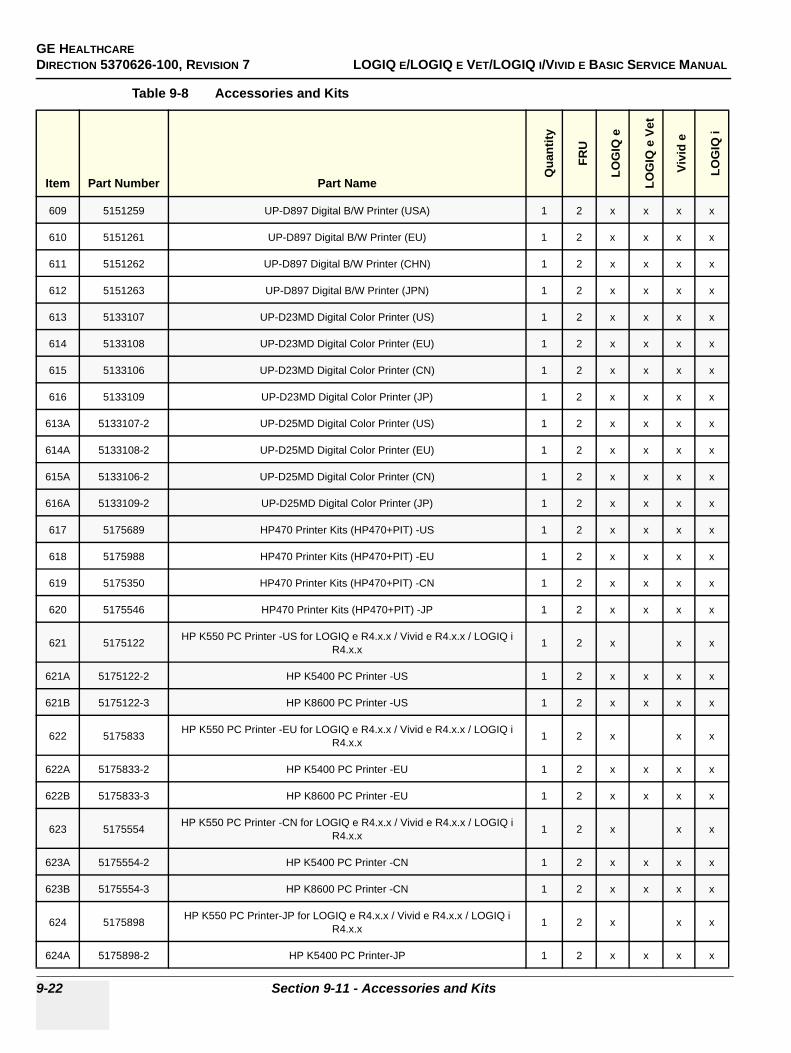
GE HEALTHCAREDIRECTION 5370626-100, REVISION 7 LOGIQ E/LOGIQ E VET/LOGIQ I/VIVID E BASIC SERVICE MANUAL
9-22 Section 9-11 - Accessories and Kits
609 5151259 UP-D897 Digital B/W Printer (USA) 1 2 x x x x
610 5151261 UP-D897 Digital B/W Printer (EU) 1 2 x x x x
611 5151262 UP-D897 Digital B/W Printer (CHN) 1 2 x x x x
612 5151263 UP-D897 Digital B/W Printer (JPN) 1 2 x x x x
613 5133107 UP-D23MD Digital Color Printer (US) 1 2 x x x x
614 5133108 UP-D23MD Digital Color Printer (EU) 1 2 x x x x
615 5133106 UP-D23MD Digital Color Printer (CN) 1 2 x x x x
616 5133109 UP-D23MD Digital Color Printer (JP) 1 2 x x x x
613A 5133107-2 UP-D25MD Digital Color Printer (US) 1 2 x x x x
614A 5133108-2 UP-D25MD Digital Color Printer (EU) 1 2 x x x x
615A 5133106-2 UP-D25MD Digital Color Printer (CN) 1 2 x x x x
616A 5133109-2 UP-D25MD Digital Color Printer (JP) 1 2 x x x x
617 5175689 HP470 Printer Kits (HP470+PIT) -US 1 2 x x x x
618 5175988 HP470 Printer Kits (HP470+PIT) -EU 1 2 x x x x
619 5175350 HP470 Printer Kits (HP470+PIT) -CN 1 2 x x x x
620 5175546 HP470 Printer Kits (HP470+PIT) -JP 1 2 x x x x
621 5175122 HP K550 PC Printer -US for LOGIQ e R4.x.x / Vivid e R4.x.x / LOGIQ i R4.x.x 1 2 x x x
621A 5175122-2 HP K5400 PC Printer -US 1 2 x x x x
621B 5175122-3 HP K8600 PC Printer -US 1 2 x x x x
622 5175833 HP K550 PC Printer -EU for LOGIQ e R4.x.x / Vivid e R4.x.x / LOGIQ i R4.x.x 1 2 x x x
622A 5175833-2 HP K5400 PC Printer -EU 1 2 x x x x
622B 5175833-3 HP K8600 PC Printer -EU 1 2 x x x x
623 5175554 HP K550 PC Printer -CN for LOGIQ e R4.x.x / Vivid e R4.x.x / LOGIQ i R4.x.x 1 2 x x x
623A 5175554-2 HP K5400 PC Printer -CN 1 2 x x x x
623B 5175554-3 HP K8600 PC Printer -CN 1 2 x x x x
624 5175898 HP K550 PC Printer-JP for LOGIQ e R4.x.x / Vivid e R4.x.x / LOGIQ i R4.x.x 1 2 x x x
624A 5175898-2 HP K5400 PC Printer-JP 1 2 x x x x
Table 9-8 Accessories and Kits
Item Part Number Part Name
Qua
ntity
FRU
LOG
IQ e
LOG
IQ e
Vet
Vivi
d e
LOG
IQ i
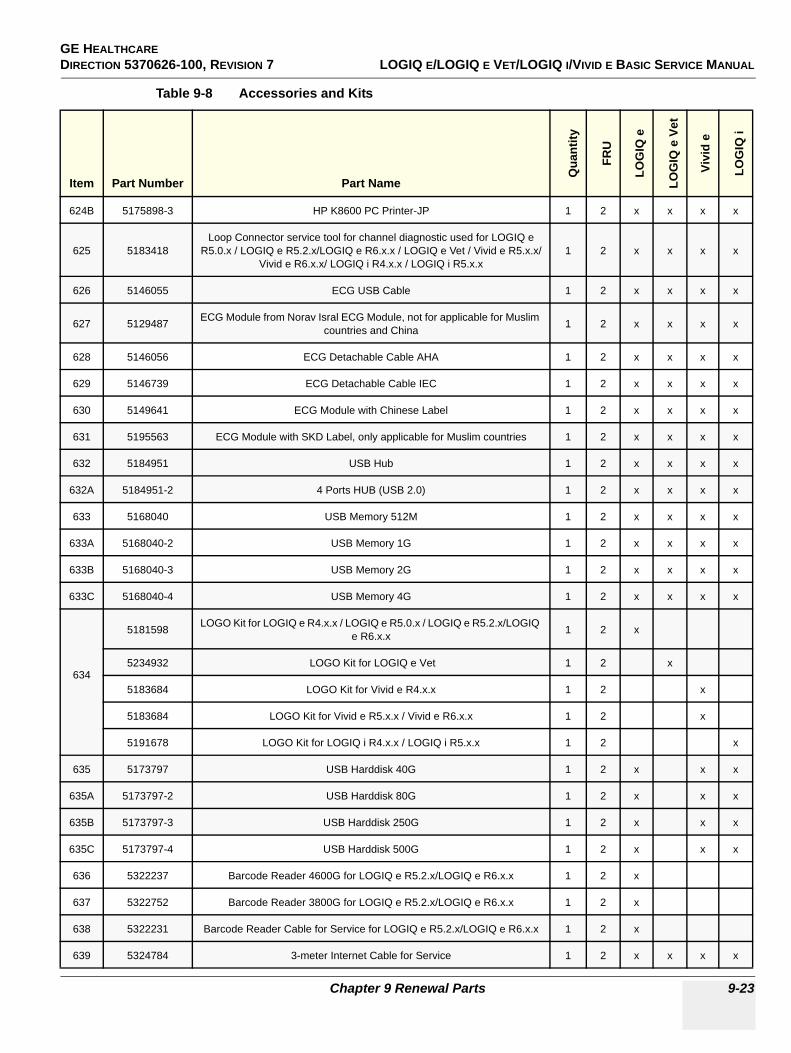
GE HEALTHCARE DIRECTION 5370626-100, REVISION 7 LOGIQ E/LOGIQ E VET/LOGIQ I/VIVID E BASIC SERVICE MANUAL
Chapter 9 Renewal Parts 9-23
624B 5175898-3 HP K8600 PC Printer-JP 1 2 x x x x
625 5183418Loop Connector service tool for channel diagnostic used for LOGIQ e
R5.0.x / LOGIQ e R5.2.x/LOGIQ e R6.x.x / LOGIQ e Vet / Vivid e R5.x.x/Vivid e R6.x.x/ LOGIQ i R4.x.x / LOGIQ i R5.x.x
1 2 x x x x
626 5146055 ECG USB Cable 1 2 x x x x
627 5129487 ECG Module from Norav Isral ECG Module, not for applicable for Muslim countries and China 1 2 x x x x
628 5146056 ECG Detachable Cable AHA 1 2 x x x x
629 5146739 ECG Detachable Cable IEC 1 2 x x x x
630 5149641 ECG Module with Chinese Label 1 2 x x x x
631 5195563 ECG Module with SKD Label, only applicable for Muslim countries 1 2 x x x x
632 5184951 USB Hub 1 2 x x x x
632A 5184951-2 4 Ports HUB (USB 2.0) 1 2 x x x x
633 5168040 USB Memory 512M 1 2 x x x x
633A 5168040-2 USB Memory 1G 1 2 x x x x
633B 5168040-3 USB Memory 2G 1 2 x x x x
633C 5168040-4 USB Memory 4G 1 2 x x x x
634
5181598 LOGO Kit for LOGIQ e R4.x.x / LOGIQ e R5.0.x / LOGIQ e R5.2.x/LOGIQ e R6.x.x 1 2 x
5234932 LOGO Kit for LOGIQ e Vet 1 2 x
5183684 LOGO Kit for Vivid e R4.x.x 1 2 x
5183684 LOGO Kit for Vivid e R5.x.x / Vivid e R6.x.x 1 2 x
5191678 LOGO Kit for LOGIQ i R4.x.x / LOGIQ i R5.x.x 1 2 x
635 5173797 USB Harddisk 40G 1 2 x x x
635A 5173797-2 USB Harddisk 80G 1 2 x x x
635B 5173797-3 USB Harddisk 250G 1 2 x x x
635C 5173797-4 USB Harddisk 500G 1 2 x x x
636 5322237 Barcode Reader 4600G for LOGIQ e R5.2.x/LOGIQ e R6.x.x 1 2 x
637 5322752 Barcode Reader 3800G for LOGIQ e R5.2.x/LOGIQ e R6.x.x 1 2 x
638 5322231 Barcode Reader Cable for Service for LOGIQ e R5.2.x/LOGIQ e R6.x.x 1 2 x
639 5324784 3-meter Internet Cable for Service 1 2 x x x x
Table 9-8 Accessories and Kits
Item Part Number Part Name
Qua
ntity
FRU
LOG
IQ e
LOG
IQ e
Vet
Vivi
d e
LOG
IQ i
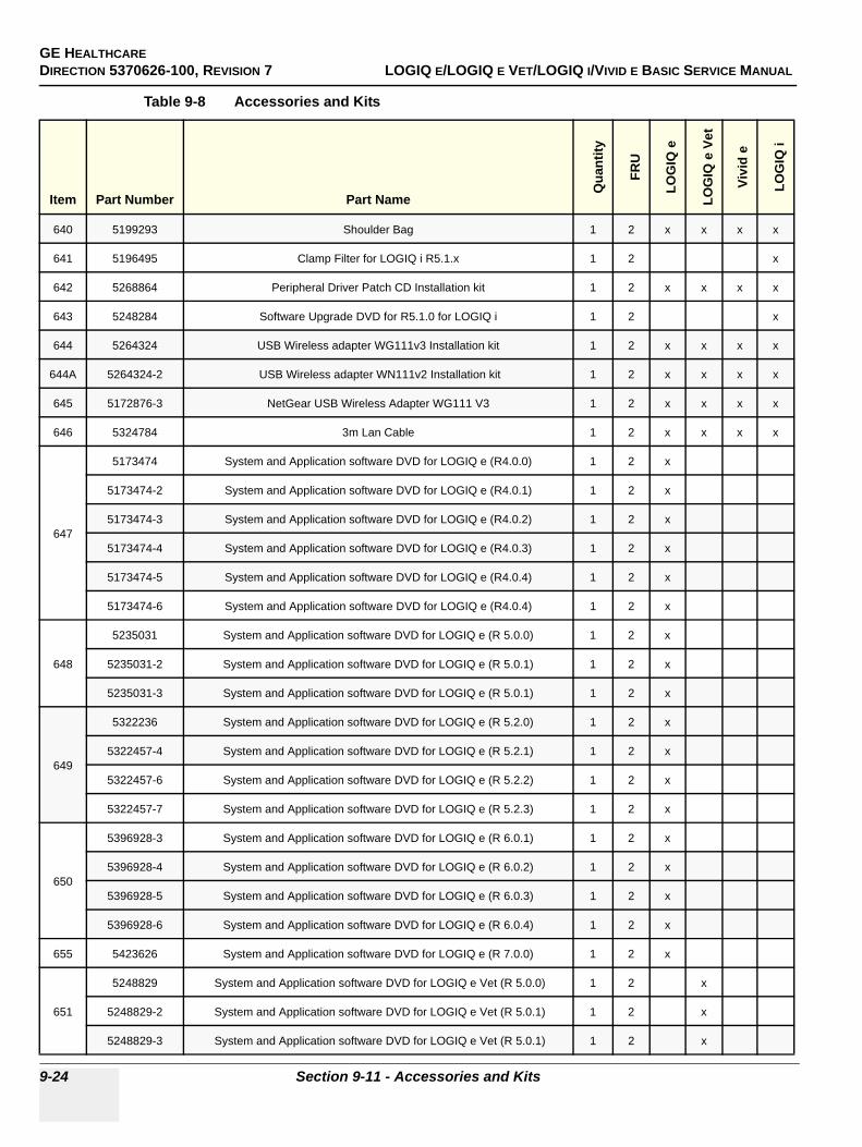
GE HEALTHCAREDIRECTION 5370626-100, REVISION 7 LOGIQ E/LOGIQ E VET/LOGIQ I/VIVID E BASIC SERVICE MANUAL
9-24 Section 9-11 - Accessories and Kits
640 5199293 Shoulder Bag 1 2 x x x x
641 5196495 Clamp Filter for LOGIQ i R5.1.x 1 2 x
642 5268864 Peripheral Driver Patch CD Installation kit 1 2 x x x x
643 5248284 Software Upgrade DVD for R5.1.0 for LOGIQ i 1 2 x
644 5264324 USB Wireless adapter WG111v3 Installation kit 1 2 x x x x
644A 5264324-2 USB Wireless adapter WN111v2 Installation kit 1 2 x x x x
645 5172876-3 NetGear USB Wireless Adapter WG111 V3 1 2 x x x x
646 5324784 3m Lan Cable 1 2 x x x x
647
5173474 System and Application software DVD for LOGIQ e (R4.0.0) 1 2 x
5173474-2 System and Application software DVD for LOGIQ e (R4.0.1) 1 2 x
5173474-3 System and Application software DVD for LOGIQ e (R4.0.2) 1 2 x
5173474-4 System and Application software DVD for LOGIQ e (R4.0.3) 1 2 x
5173474-5 System and Application software DVD for LOGIQ e (R4.0.4) 1 2 x
5173474-6 System and Application software DVD for LOGIQ e (R4.0.4) 1 2 x
648
5235031 System and Application software DVD for LOGIQ e (R 5.0.0) 1 2 x
5235031-2 System and Application software DVD for LOGIQ e (R 5.0.1) 1 2 x
5235031-3 System and Application software DVD for LOGIQ e (R 5.0.1) 1 2 x
649
5322236 System and Application software DVD for LOGIQ e (R 5.2.0) 1 2 x
5322457-4 System and Application software DVD for LOGIQ e (R 5.2.1) 1 2 x
5322457-6 System and Application software DVD for LOGIQ e (R 5.2.2) 1 2 x
5322457-7 System and Application software DVD for LOGIQ e (R 5.2.3) 1 2 x
650
5396928-3 System and Application software DVD for LOGIQ e (R 6.0.1) 1 2 x
5396928-4 System and Application software DVD for LOGIQ e (R 6.0.2) 1 2 x
5396928-5 System and Application software DVD for LOGIQ e (R 6.0.3) 1 2 x
5396928-6 System and Application software DVD for LOGIQ e (R 6.0.4) 1 2 x
655 5423626 System and Application software DVD for LOGIQ e (R 7.0.0) 1 2 x
651
5248829 System and Application software DVD for LOGIQ e Vet (R 5.0.0) 1 2 x
5248829-2 System and Application software DVD for LOGIQ e Vet (R 5.0.1) 1 2 x
5248829-3 System and Application software DVD for LOGIQ e Vet (R 5.0.1) 1 2 x
Table 9-8 Accessories and Kits
Item Part Number Part Name
Qua
ntity
FRU
LOG
IQ e
LOG
IQ e
Vet
Vivi
d e
LOG
IQ i
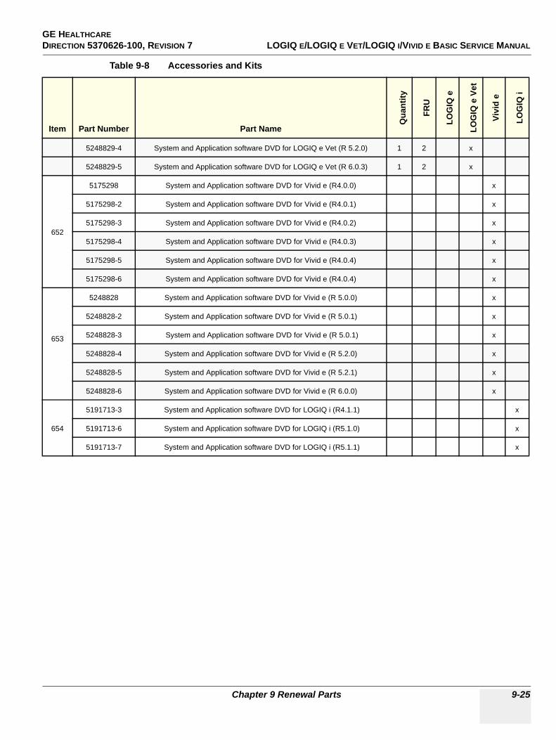
GE HEALTHCARE DIRECTION 5370626-100, REVISION 7 LOGIQ E/LOGIQ E VET/LOGIQ I/VIVID E BASIC SERVICE MANUAL
Chapter 9 Renewal Parts 9-25
5248829-4 System and Application software DVD for LOGIQ e Vet (R 5.2.0) 1 2 x
5248829-5 System and Application software DVD for LOGIQ e Vet (R 6.0.3) 1 2 x
652
5175298 System and Application software DVD for Vivid e (R4.0.0) x
5175298-2 System and Application software DVD for Vivid e (R4.0.1) x
5175298-3 System and Application software DVD for Vivid e (R4.0.2) x
5175298-4 System and Application software DVD for Vivid e (R4.0.3) x
5175298-5 System and Application software DVD for Vivid e (R4.0.4) x
5175298-6 System and Application software DVD for Vivid e (R4.0.4) x
653
5248828 System and Application software DVD for Vivid e (R 5.0.0) x
5248828-2 System and Application software DVD for Vivid e (R 5.0.1) x
5248828-3 System and Application software DVD for Vivid e (R 5.0.1) x
5248828-4 System and Application software DVD for Vivid e (R 5.2.0) x
5248828-5 System and Application software DVD for Vivid e (R 5.2.1) x
5248828-6 System and Application software DVD for Vivid e (R 6.0.0) x
654
5191713-3 System and Application software DVD for LOGIQ i (R4.1.1) x
5191713-6 System and Application software DVD for LOGIQ i (R5.1.0) x
5191713-7 System and Application software DVD for LOGIQ i (R5.1.1) x
Table 9-8 Accessories and Kits
Item Part Number Part Name
Qua
ntity
FRU
LOG
IQ e
LOG
IQ e
Vet
Vivi
d e
LOG
IQ i
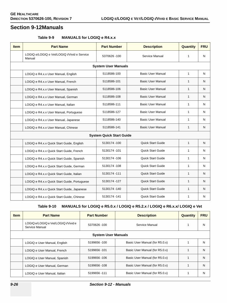
GE HEALTHCAREDIRECTION 5370626-100, REVISION 7 LOGIQ E/LOGIQ E VET/LOGIQ I/VIVID E BASIC SERVICE MANUAL
9-26 Section 9-12 - Manuals
Section 9-12Manuals
Table 9-9 MANUALS for LOGIQ e R4.x.x
Item Part Name Part Number Description Quantity FRU
LOGIQ e/LOGIQ e Vet/LOGIQ i/Vivid e Service Manual
5370626 -100 Service Manual 1 N
System User Manuals
LOGIQ e R4.x.x User Manual, English 5118586-100 Basic User Manual 1 N
LOGIQ e R4.x.x User Manual, French 5118586-101 Basic User Manual 1 N
LOGIQ e R4.x.x User Manual, Spanish 5118586-106 Basic User Manual 1 N
LOGIQ e R4.x.x User Manual, German 5118586-108 Basic User Manual 1 N
LOGIQ e R4.x.x User Manual, Italian 5118586-111 Basic User Manual 1 N
LOGIQ e R4.x.x User Manual, Portuguese 5118586-127 Basic User Manual 1 N
LOGIQ e R4.x.x User Manual, Japanese 5118586-140 Basic User Manual 1 N
LOGIQ e R4.x.x User Manual, Chinese 5118586-141 Basic User Manual 1 N
System Quick Start Guide
LOGIQ e R4.x.x Quick Start Guide, English 5130174 -100 Quick Start Guide 1 N
LOGIQ e R4.x.x Quick Start Guide, French 5130174 -101 Quick Start Guide 1 N
LOGIQ e R4.x.x Quick Start Guide, Spanish 5130174 -106 Quick Start Guide 1 N
LOGIQ e R4.x.x Quick Start Guide, German 5130174 -108 Quick Start Guide 1 N
LOGIQ e R4.x.x Quick Start Guide, Italian 5130174 -111 Quick Start Guide 1 N
LOGIQ e R4.x.x Quick Start Guide, Portuguese 5130174 -127 Quick Start Guide 1 N
LOGIQ e R4.x.x Quick Start Guide, Japanese 5130174 -140 Quick Start Guide 1 N
LOGIQ e R4.x.x Quick Start Guide, Chinese 5130174 -141 Quick Start Guide 1 N
Table 9-10 MANUALS for LOGIQ e R5.0.x / LOGIQ e R5.2.x / LOGIQ e R6.x.x/ LOGIQ e Vet
Item Part Name Part Number Description Quantity FRU
LOGIQ e/LOGIQ e Vet/LOGIQ i/Vivid e Service Manual
5370626 -100 Service Manual 1 N
System User Manuals
LOGIQ e User Manual, English 5199656 -100 Basic User Manual (for R5.0.x) 1 N
LOGIQ e User Manual, French 5199656 -101 Basic User Manual (for R5.0.x) 1 N
LOGIQ e User Manual, Spanish 5199656 -106 Basic User Manual (for R5.0.x) 1 N
LOGIQ e User Manual, German 5199656 -108 Basic User Manual (for R5.0.x) 1 N
LOGIQ e User Manual, Italian 5199656 -111 Basic User Manual (for R5.0.x) 1 N
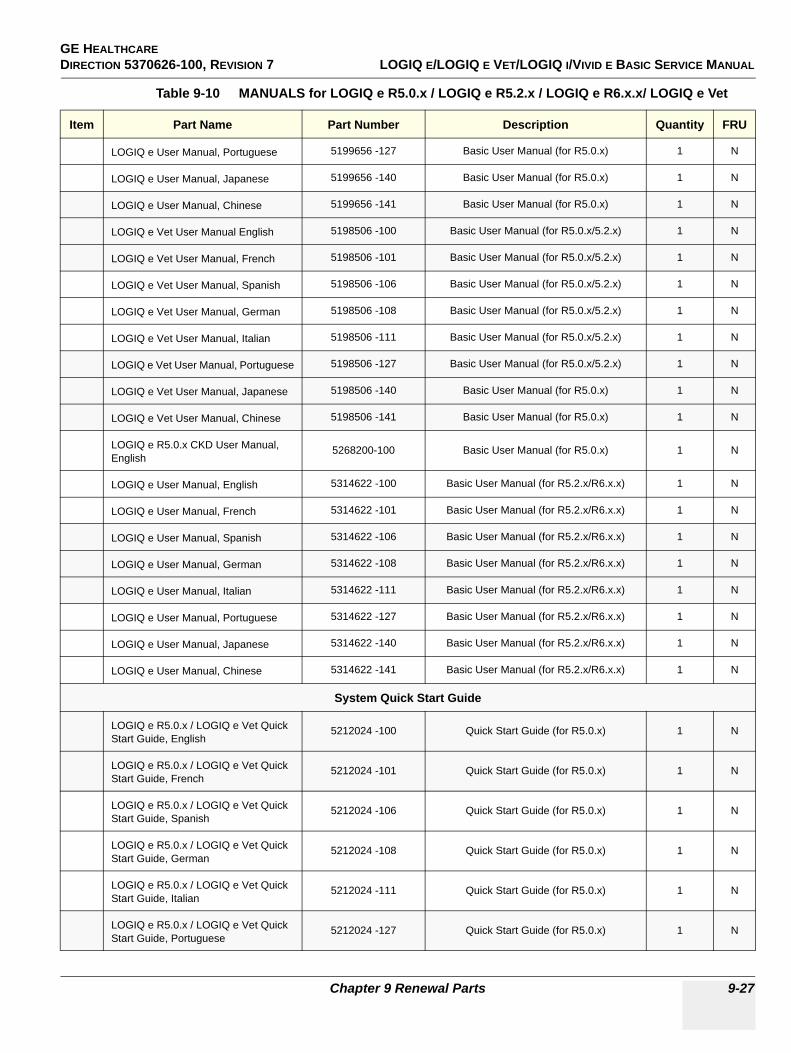
GE HEALTHCARE DIRECTION 5370626-100, REVISION 7 LOGIQ E/LOGIQ E VET/LOGIQ I/VIVID E BASIC SERVICE MANUAL
Chapter 9 Renewal Parts 9-27
LOGIQ e User Manual, Portuguese 5199656 -127 Basic User Manual (for R5.0.x) 1 N
LOGIQ e User Manual, Japanese 5199656 -140 Basic User Manual (for R5.0.x) 1 N
LOGIQ e User Manual, Chinese 5199656 -141 Basic User Manual (for R5.0.x) 1 N
LOGIQ e Vet User Manual English 5198506 -100 Basic User Manual (for R5.0.x/5.2.x) 1 N
LOGIQ e Vet User Manual, French 5198506 -101 Basic User Manual (for R5.0.x/5.2.x) 1 N
LOGIQ e Vet User Manual, Spanish 5198506 -106 Basic User Manual (for R5.0.x/5.2.x) 1 N
LOGIQ e Vet User Manual, German 5198506 -108 Basic User Manual (for R5.0.x/5.2.x) 1 N
LOGIQ e Vet User Manual, Italian 5198506 -111 Basic User Manual (for R5.0.x/5.2.x) 1 N
LOGIQ e Vet User Manual, Portuguese 5198506 -127 Basic User Manual (for R5.0.x/5.2.x) 1 N
LOGIQ e Vet User Manual, Japanese 5198506 -140 Basic User Manual (for R5.0.x) 1 N
LOGIQ e Vet User Manual, Chinese 5198506 -141 Basic User Manual (for R5.0.x) 1 N
LOGIQ e R5.0.x CKD User Manual, English
5268200-100 Basic User Manual (for R5.0.x) 1 N
LOGIQ e User Manual, English 5314622 -100 Basic User Manual (for R5.2.x/R6.x.x) 1 N
LOGIQ e User Manual, French 5314622 -101 Basic User Manual (for R5.2.x/R6.x.x) 1 N
LOGIQ e User Manual, Spanish 5314622 -106 Basic User Manual (for R5.2.x/R6.x.x) 1 N
LOGIQ e User Manual, German 5314622 -108 Basic User Manual (for R5.2.x/R6.x.x) 1 N
LOGIQ e User Manual, Italian 5314622 -111 Basic User Manual (for R5.2.x/R6.x.x) 1 N
LOGIQ e User Manual, Portuguese 5314622 -127 Basic User Manual (for R5.2.x/R6.x.x) 1 N
LOGIQ e User Manual, Japanese 5314622 -140 Basic User Manual (for R5.2.x/R6.x.x) 1 N
LOGIQ e User Manual, Chinese 5314622 -141 Basic User Manual (for R5.2.x/R6.x.x) 1 N
System Quick Start Guide
LOGIQ e R5.0.x / LOGIQ e Vet Quick Start Guide, English
5212024 -100 Quick Start Guide (for R5.0.x) 1 N
LOGIQ e R5.0.x / LOGIQ e Vet Quick Start Guide, French
5212024 -101 Quick Start Guide (for R5.0.x) 1 N
LOGIQ e R5.0.x / LOGIQ e Vet Quick Start Guide, Spanish
5212024 -106 Quick Start Guide (for R5.0.x) 1 N
LOGIQ e R5.0.x / LOGIQ e Vet Quick Start Guide, German
5212024 -108 Quick Start Guide (for R5.0.x) 1 N
LOGIQ e R5.0.x / LOGIQ e Vet Quick Start Guide, Italian
5212024 -111 Quick Start Guide (for R5.0.x) 1 N
LOGIQ e R5.0.x / LOGIQ e Vet Quick Start Guide, Portuguese
5212024 -127 Quick Start Guide (for R5.0.x) 1 N
Table 9-10 MANUALS for LOGIQ e R5.0.x / LOGIQ e R5.2.x / LOGIQ e R6.x.x/ LOGIQ e Vet
Item Part Name Part Number Description Quantity FRU
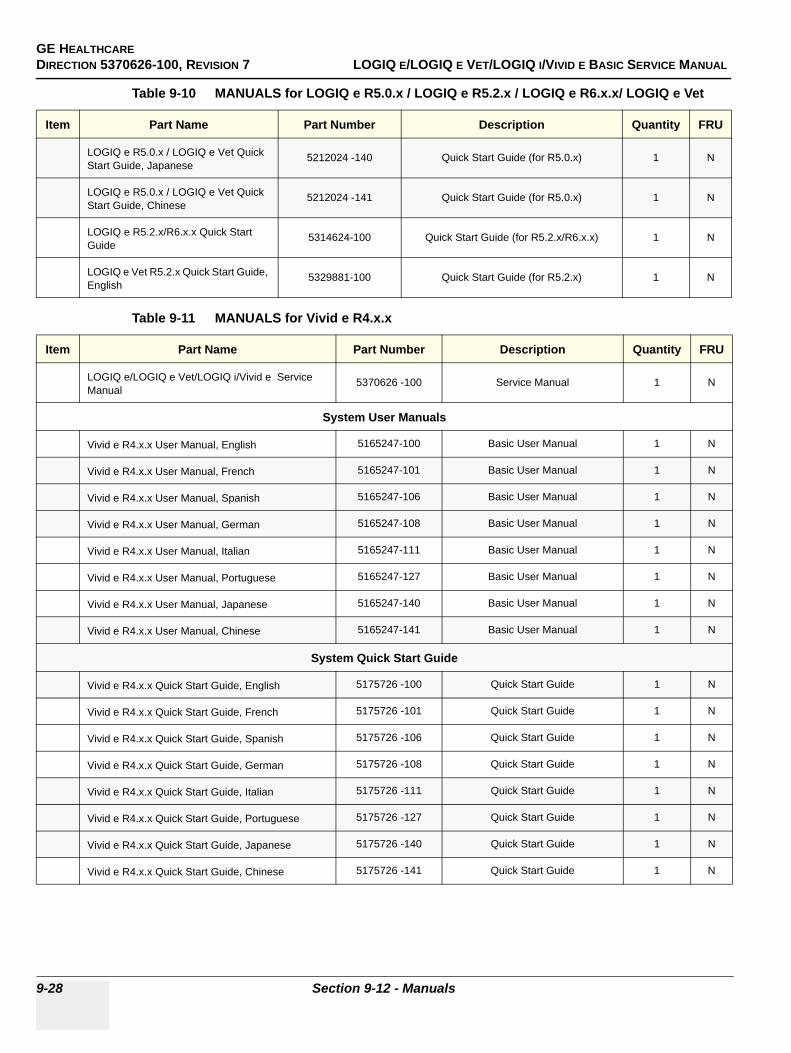
GE HEALTHCAREDIRECTION 5370626-100, REVISION 7 LOGIQ E/LOGIQ E VET/LOGIQ I/VIVID E BASIC SERVICE MANUAL
9-28 Section 9-12 - Manuals
LOGIQ e R5.0.x / LOGIQ e Vet Quick Start Guide, Japanese
5212024 -140 Quick Start Guide (for R5.0.x) 1 N
LOGIQ e R5.0.x / LOGIQ e Vet Quick Start Guide, Chinese
5212024 -141 Quick Start Guide (for R5.0.x) 1 N
LOGIQ e R5.2.x/R6.x.x Quick Start Guide
5314624-100 Quick Start Guide (for R5.2.x/R6.x.x) 1 N
LOGIQ e Vet R5.2.x Quick Start Guide, English
5329881-100 Quick Start Guide (for R5.2.x) 1 N
Table 9-11 MANUALS for Vivid e R4.x.x
Item Part Name Part Number Description Quantity FRU
LOGIQ e/LOGIQ e Vet/LOGIQ i/Vivid e Service Manual
5370626 -100 Service Manual 1 N
System User Manuals
Vivid e R4.x.x User Manual, English 5165247-100 Basic User Manual 1 N
Vivid e R4.x.x User Manual, French 5165247-101 Basic User Manual 1 N
Vivid e R4.x.x User Manual, Spanish 5165247-106 Basic User Manual 1 N
Vivid e R4.x.x User Manual, German 5165247-108 Basic User Manual 1 N
Vivid e R4.x.x User Manual, Italian 5165247-111 Basic User Manual 1 N
Vivid e R4.x.x User Manual, Portuguese 5165247-127 Basic User Manual 1 N
Vivid e R4.x.x User Manual, Japanese 5165247-140 Basic User Manual 1 N
Vivid e R4.x.x User Manual, Chinese 5165247-141 Basic User Manual 1 N
System Quick Start Guide
Vivid e R4.x.x Quick Start Guide, English 5175726 -100 Quick Start Guide 1 N
Vivid e R4.x.x Quick Start Guide, French 5175726 -101 Quick Start Guide 1 N
Vivid e R4.x.x Quick Start Guide, Spanish 5175726 -106 Quick Start Guide 1 N
Vivid e R4.x.x Quick Start Guide, German 5175726 -108 Quick Start Guide 1 N
Vivid e R4.x.x Quick Start Guide, Italian 5175726 -111 Quick Start Guide 1 N
Vivid e R4.x.x Quick Start Guide, Portuguese 5175726 -127 Quick Start Guide 1 N
Vivid e R4.x.x Quick Start Guide, Japanese 5175726 -140 Quick Start Guide 1 N
Vivid e R4.x.x Quick Start Guide, Chinese 5175726 -141 Quick Start Guide 1 N
Table 9-10 MANUALS for LOGIQ e R5.0.x / LOGIQ e R5.2.x / LOGIQ e R6.x.x/ LOGIQ e Vet
Item Part Name Part Number Description Quantity FRU
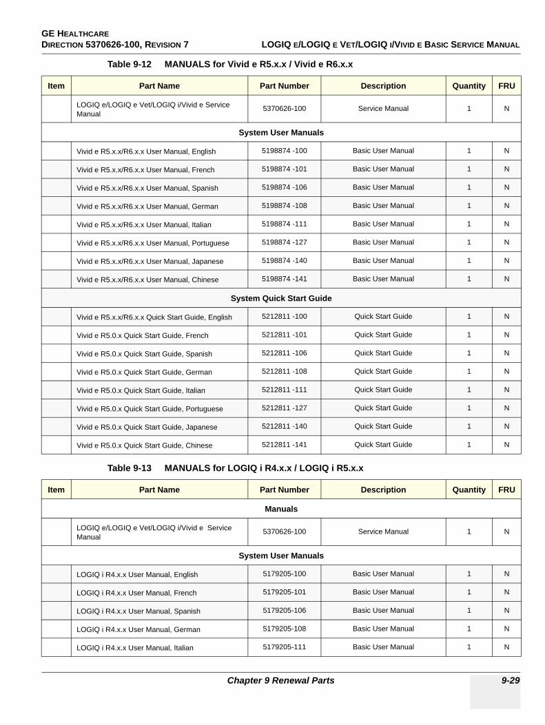
GE HEALTHCARE DIRECTION 5370626-100, REVISION 7 LOGIQ E/LOGIQ E VET/LOGIQ I/VIVID E BASIC SERVICE MANUAL
Chapter 9 Renewal Parts 9-29
Table 9-12 MANUALS for Vivid e R5.x.x / Vivid e R6.x.x
Item Part Name Part Number Description Quantity FRU
LOGIQ e/LOGIQ e Vet/LOGIQ i/Vivid e Service Manual
5370626-100 Service Manual 1 N
System User Manuals
Vivid e R5.x.x/R6.x.x User Manual, English 5198874 -100 Basic User Manual 1 N
Vivid e R5.x.x/R6.x.x User Manual, French 5198874 -101 Basic User Manual 1 N
Vivid e R5.x.x/R6.x.x User Manual, Spanish 5198874 -106 Basic User Manual 1 N
Vivid e R5.x.x/R6.x.x User Manual, German 5198874 -108 Basic User Manual 1 N
Vivid e R5.x.x/R6.x.x User Manual, Italian 5198874 -111 Basic User Manual 1 N
Vivid e R5.x.x/R6.x.x User Manual, Portuguese 5198874 -127 Basic User Manual 1 N
Vivid e R5.x.x/R6.x.x User Manual, Japanese 5198874 -140 Basic User Manual 1 N
Vivid e R5.x.x/R6.x.x User Manual, Chinese 5198874 -141 Basic User Manual 1 N
System Quick Start Guide
Vivid e R5.x.x/R6.x.x Quick Start Guide, English 5212811 -100 Quick Start Guide 1 N
Vivid e R5.0.x Quick Start Guide, French 5212811 -101 Quick Start Guide 1 N
Vivid e R5.0.x Quick Start Guide, Spanish 5212811 -106 Quick Start Guide 1 N
Vivid e R5.0.x Quick Start Guide, German 5212811 -108 Quick Start Guide 1 N
Vivid e R5.0.x Quick Start Guide, Italian 5212811 -111 Quick Start Guide 1 N
Vivid e R5.0.x Quick Start Guide, Portuguese 5212811 -127 Quick Start Guide 1 N
Vivid e R5.0.x Quick Start Guide, Japanese 5212811 -140 Quick Start Guide 1 N
Vivid e R5.0.x Quick Start Guide, Chinese 5212811 -141 Quick Start Guide 1 N
Table 9-13 MANUALS for LOGIQ i R4.x.x / LOGIQ i R5.x.x
Item Part Name Part Number Description Quantity FRU
Manuals
LOGIQ e/LOGIQ e Vet/LOGIQ i/Vivid e Service Manual
5370626-100 Service Manual 1 N
System User Manuals
LOGIQ i R4.x.x User Manual, English 5179205-100 Basic User Manual 1 N
LOGIQ i R4.x.x User Manual, French 5179205-101 Basic User Manual 1 N
LOGIQ i R4.x.x User Manual, Spanish 5179205-106 Basic User Manual 1 N
LOGIQ i R4.x.x User Manual, German 5179205-108 Basic User Manual 1 N
LOGIQ i R4.x.x User Manual, Italian 5179205-111 Basic User Manual 1 N
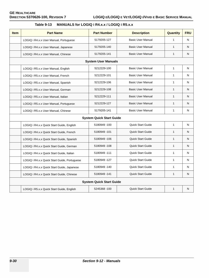
GE HEALTHCAREDIRECTION 5370626-100, REVISION 7 LOGIQ E/LOGIQ E VET/LOGIQ I/VIVID E BASIC SERVICE MANUAL
9-30 Section 9-12 - Manuals
LOGIQ i R4.x.x User Manual, Portuguese 5179205-127 Basic User Manual 1 N
LOGIQ i R4.x.x User Manual, Japanese 5179205-140 Basic User Manual 1 N
LOGIQ i R4.x.x User Manual, Chinese 5179205-141 Basic User Manual 1 N
System User Manuals
LOGIQ i R5.x.x User Manual, English 5212229-100 Basic User Manual 1 N
LOGIQ i R5.x.x User Manual, French 5212229-101 Basic User Manual 1 N
LOGIQ i R5.x.x User Manual, Spanish 5212229-106 Basic User Manual 1 N
LOGIQ i R5.x.x User Manual, German 5212229-108 Basic User Manual 1 N
LOGIQ i R5.x.x User Manual, Italian 5212229-111 Basic User Manual 1 N
LOGIQ i R5.x.x User Manual, Portuguese 5212229-127 Basic User Manual 1 N
LOGIQ i R5.x.x User Manual, Chinese 5179205-141 Basic User Manual 1 N
System Quick Start Guide
LOGIQ i R4.x.x Quick Start Guide, English 5180949 -100 Quick Start Guide 1 N
LOGIQ i R4.x.x Quick Start Guide, French 5180949 -101 Quick Start Guide 1 N
LOGIQ i R4.x.x Quick Start Guide, Spanish 5180949 -106 Quick Start Guide 1 N
LOGIQ i R4.x.x Quick Start Guide, German 5180949 -108 Quick Start Guide 1 N
LOGIQ i R4.x.x Quick Start Guide, Italian 5180949 -111 Quick Start Guide 1 N
LOGIQ i R4.x.x Quick Start Guide, Portuguese 5180949 -127 Quick Start Guide 1 N
LOGIQ i R4.x.x Quick Start Guide, Japanese 5180949 -140 Quick Start Guide 1 N
LOGIQ i R4.x.x Quick Start Guide, Chinese 5180949 -141 Quick Start Guide 1 N
System Quick Start Guide
LOGIQ i R5.x.x Quick Start Guide, English 5245368 -100 Quick Start Guide 1 N
Table 9-13 MANUALS for LOGIQ i R4.x.x / LOGIQ i R5.x.x
Item Part Name Part Number Description Quantity FRU
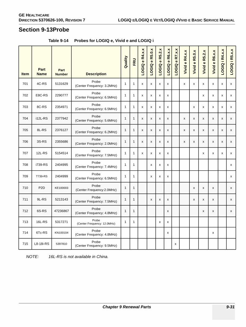
GE HEALTHCARE DIRECTION 5370626-100, REVISION 7 LOGIQ E/LOGIQ E VET/LOGIQ I/VIVID E BASIC SERVICE MANUAL
Chapter 9 Renewal Parts 9-31
Section 9-13Probe
NOTE: 16L-RS is not available in China.
Table 9-14 Probes for LOGIQ e, Vivid e and LOGIQ i
ItemPart
NamePart
Number Description
Qua
lity
FRU
LOG
IQ e
R4.
x.x
LOG
IQ e
R5.
0.x
LOG
IQ e
R5.
2.x
LOG
IQ e
R6.
x.x
LOG
IQ e
R7.
x.x
Vivi
d e
R4.
x.x
Vivi
d e
R5.
0.x
Vivi
d e
R5.
2.x
Vivi
d e
R6.
x.x
LOG
IQ i
R4.
x.x
LOG
IQ i
R5.
x.x
701 4C-RS 5131629 Probe (Center Frequency: 3.2MHz) 1 1 x x x x x x x x x x
702 E8C-RS 2290777 Probe (Center Frequency: 6.5MHz) 1 1 x x x x x x x x
703 8C-RS 2354971 Probe (Center Frequency: 6.5MHz) 1 1 x x x x x x x x x
704 i12L-RS 2377942 Probe (Center Frequency: 5.6MHz) 1 1 x x x x x x x x x x
705 8L-RS 2376127 Probe(Center Frequency: 6.2MHz) 1 1 x x x x x x x x x x
706 3S-RS 2355686 Probe (Center Frequency: 2.0MHz) 1 1 x x x x x x x x x x
707 12L-RS 5154514 Probe (Center Frequency: 7.5MHz) 1 1 x x x x x x x x
708 i739-RS 2404995 Probe (Center Frequency: 7.4MHz) 1 1 x x x x
709 T739-RS 2404999 Probe(Center Frequency: 6.5MHz) 1 1 x x x x
710 P2D KE100003Probe
(Center Frequency:2.0MHz) 1 1 x x x x
711 9L-RS 5213143 Probe(Center Frequency: 7.5MHz) 1 1 x x x x x x x
712 6S-RS 47236867 Probe(Center Frequency: 4.8MHz) 1 1 x x x x
713 16L-RS 5317271 Probe(Center Frequency: 12.0MHz) 1 1 x x
714 6Tc-RS KN100104 Probe(Center Frequency: 4.8MHz) x x
715 L8-18i-RS 5397810 Probe(Center Frequency: 9.5MHz) x
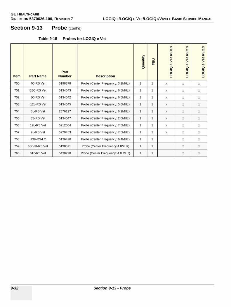
GE HEALTHCAREDIRECTION 5370626-100, REVISION 7 LOGIQ E/LOGIQ E VET/LOGIQ I/VIVID E BASIC SERVICE MANUAL
9-32 Section 9-13 - Probe
Section 9-13 Probe (cont’d)
Table 9-15 Probes for LOGIQ e Vet
Item Part NamePart
Number Description
Qua
ntity
FRU
LOG
IQ e
Vet
R5.
0.x
LOG
IQ e
Vet
R5.
2.x
LOG
IQ e
Vet
R5.
2.x
750 4C-RS Vet 5198378 Probe (Center Frequency: 3.2MHz) 1 1 x x x
751 E8C-RS Vet 5134643 Probe (Center Frequency: 6.5MHz) 1 1 x x x
752 8C-RS Vet 5134642 Probe (Center Frequency: 6.5MHz) 1 1 x x x
753 i12L-RS Vet 5134645 Probe (Center Frequency: 5.6MHz) 1 1 x x x
754 8L-RS Vet 2376127 Probe (Center Frequency: 6.2MHz) 1 1 x x x
755 3S-RS Vet 5134647 Probe (Center Frequency: 2.0MHz) 1 1 x x x
756 12L-RS Vet 5212304 Probe (Center Frequency: 7.5MHz) 1 1 x x x
757 9L-RS Vet 5220453 Probe (Center Frequency: 7.5MHz) 1 1 x x x
758 i739-RS-LC 5136420 Probe (Center Frequency: 6.4MHz) 1 1 x x
759 6S Vet-RS Vet 5198571 Probe (Center Frequency:4.8MHz) 1 1 x x
760 6Tc-RS Vet 5430790 Probe (Center Frequency: 4.8 MHz) 1 1 x x
GE HEALTHCAREDIRECTION 5370626-100, REVISION 7 LOGIQ E/LOGIQ E VET/LOGIQ I/VIVID E BASIC SERVICE MANUAL
Chapter 10 Care & Maintenance 10-1
Chapter 10Care & Maintenance
Section 10-1 Overview
10-1-1 Periodic Maintenance Inspections It has been determined by engineering that your LOGIQ e/LOGIQ e Vet/LOGIQ i/Vivid e system does not have any high wear components that fail with use, therefore no Periodic Maintenance Inspections are mandatory. Some Customers Quality Assurance Programs may require additional tasks and or inspections at a different frequency than listed in this manual.
10-1-2 Purpose of Chapter 10This chapter describes Care & Maintenance on the scanner and peripherals. These procedures are intended to maintain the quality of the ultrasound systems performance. Read this chapter completely and familiarize yourself with the procedures before performing a task.
Table 10-1 Contents in Chapter 10
Section Description Page Number
10-1 Overview 10-1
10-2 Why do Maintenance 10-2
10-3 Maintenance Task Schedule 10-2
10-4 Tools Required 10-4
10-5 System Maintenance 10-5
10-6 Electrical Safety Tests 10-11
10-7 When There's Too Much Leakage Current... 10-18
CAUTION Practice good ESD prevention. Wear an anti–static strap when handling electronic parts and even when disconnecting/connecting cables.
DANGER BE SURE TO DISCONNECT THE SYSTEM POWER PLUG BEFORE YOU REMOVE ANY PARTS. BE CAUTIOUS WHENEVER POWER IS STILL ON AND COVERS ARE REMOVED.
CAUTION Do not pull out or insert circuit boards while power is ON.
CAUTION Do not operate this unit unless all board covers and frame panels are securely in place. System performance and cooling require this.
GE HEALTHCAREDIRECTION 5370626-100, REVISION 7 LOGIQ E/LOGIQ E VET/LOGIQ I/VIVID E BASIC SERVICE MANUAL
10-2 Section 10-2 - Why do Maintenance
Section 10-2Why do Maintenance
10-2-1 Keeping RecordsIt is good business practice that ultrasound facilities maintain records of periodic and corrective maintenance. The Ultrasound Periodic Maintenance Inspection Certificate provides the customer with documentation that the ultrasound scanner is maintained on a periodic basis.
A copy of the Ultrasound Periodic Maintenance Inspection Certificate should be kept in the same room or near the scanner.
10-2-2 Quality AssuranceIn order to gain accreditation from organizations such as the American College of Radiology (USA), it is the customer’s responsibility to have a quality assurance program in place for each scanner. The program must be directed by a medical physicists, the supervising radiologist/physician or appropriate designee.
Routine quality control testing must occur regularly. The same tests are performed during each period so that changes can be monitored over time and effective corrective action can be taken.
Testing results, corrective action and the effects of corrective action must be documented and maintained on the site.
Your GE service representative can help you with establishing, performing and maintaining records for a quality assurance program. Please contact us for coverage information and/or price for service.
Section 10-3Maintenance Task Schedule
10-3-1 How often should care & maintenance tasks be performed?The Care & Maintenance Task Schedule (provided on page 10-3) specifies how often your LOGIQ e/LOGIQ e Vet/LOGIQ i/Vivid e should be serviced and outlines items requiring special attention.
NOTE: It is the customer’s responsibility to ensure the LOGIQ e/LOGIQ e Vet/LOGIQ i/Vivid e care & maintenance is performed as scheduled in order to retain its high level of safety, dependability and performance.
Your GE Service Representative has an in-depth knowlegde of your LOGIQ e/LOGIQ e Vet/LOGIQ i/Vivid e ultrasound scanning system and can best provide competent, efficient service. Please contact us for coverage information and/or price for service.
The service procedures and recommended intervals shown in the Care & Maintenance Task Schedule assumes that you use your LOGIQ e/LOGIQ e Vet/LOGIQ i/Vivid e for an average patient load (10-12 per day) and use it as a primary mobile unit which is transported between diagnostic facilities.
NOTE: If conditions exist which exceed typical usage and patient load, then it is recommended to increase the maintenance frequencies.
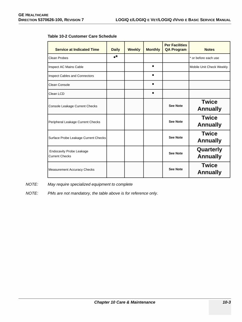
GE HEALTHCAREDIRECTION 5370626-100, REVISION 7 LOGIQ E/LOGIQ E VET/LOGIQ I/VIVID E BASIC SERVICE MANUAL
Chapter 10 Care & Maintenance 10-3
NOTE: May require specialized equipment to complete
NOTE: PMs are not mandatory, the table above is for reference only.
Table 10-2 Customer Care Schedule
Service at Indicated Time Daily Weekly MonthlyPer Facilities QA Program Notes
Clean Probes •* * or before each use
Inspect AC Mains Cable • Mobile Unit Check Weekly
Inspect Cables and Connectors •Clean Console •Clean LCD •
Console Leakage Current Checks See NoteTwice
Annually
Peripheral Leakage Current Checks See NoteTwice
Annually
Surface Probe Leakage Current Checks See NoteTwice
Annually
Endocavity Probe Leakage Current Checks
See NoteQuarterly Annually
Measurement Accuracy Checks See NoteTwice
Annually
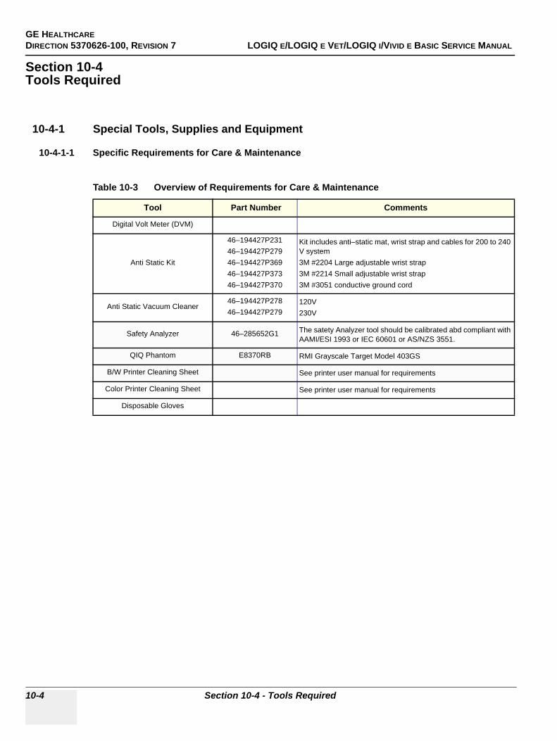
GE HEALTHCAREDIRECTION 5370626-100, REVISION 7 LOGIQ E/LOGIQ E VET/LOGIQ I/VIVID E BASIC SERVICE MANUAL
10-4 Section 10-4 - Tools Required
Section 10-4Tools Required
10-4-1 Special Tools, Supplies and Equipment
10-4-1-1 Specific Requirements for Care & Maintenance
Table 10-3 Overview of Requirements for Care & Maintenance
Tool Part Number Comments
Digital Volt Meter (DVM)
Anti Static Kit
46–194427P23146–194427P27946–194427P36946–194427P37346–194427P370
Kit includes anti–static mat, wrist strap and cables for 200 to 240 V system3M #2204 Large adjustable wrist strap3M #2214 Small adjustable wrist strap3M #3051 conductive ground cord
Anti Static Vacuum Cleaner46–194427P27846–194427P279
120V230V
Safety Analyzer 46–285652G1 The satety Analyzer tool should be calibrated abd compliant with AAMI/ESI 1993 or IEC 60601 or AS/NZS 3551.
QIQ Phantom E8370RB RMI Grayscale Target Model 403GS
B/W Printer Cleaning Sheet See printer user manual for requirements
Color Printer Cleaning Sheet See printer user manual for requirements
Disposable Gloves
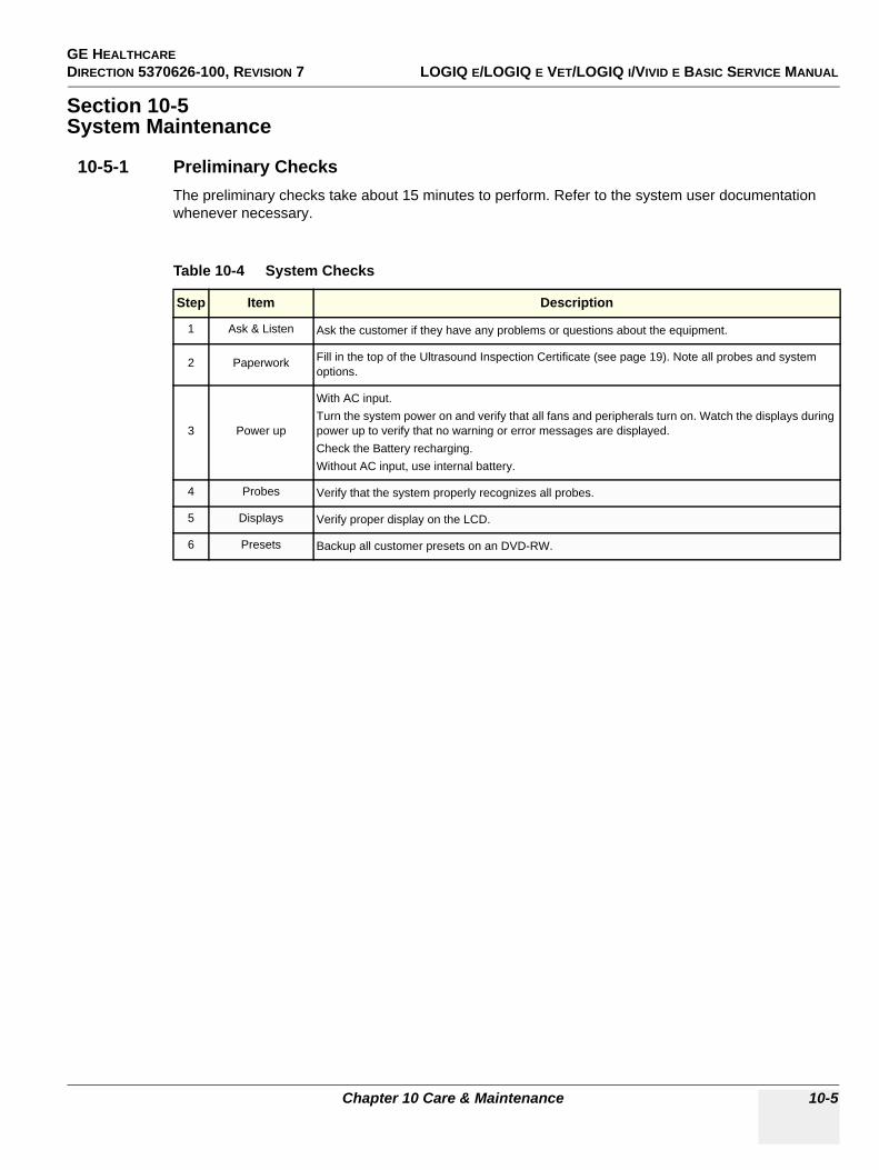
GE HEALTHCAREDIRECTION 5370626-100, REVISION 7 LOGIQ E/LOGIQ E VET/LOGIQ I/VIVID E BASIC SERVICE MANUAL
Chapter 10 Care & Maintenance 10-5
Section 10-5System Maintenance
10-5-1 Preliminary ChecksThe preliminary checks take about 15 minutes to perform. Refer to the system user documentation whenever necessary.
Table 10-4 System Checks
Step Item Description
1 Ask & Listen Ask the customer if they have any problems or questions about the equipment.
2 Paperwork Fill in the top of the Ultrasound Inspection Certificate (see page 19). Note all probes and system options.
3 Power up
With AC input.Turn the system power on and verify that all fans and peripherals turn on. Watch the displays during power up to verify that no warning or error messages are displayed.Check the Battery recharging.Without AC input, use internal battery.
4 Probes Verify that the system properly recognizes all probes.
5 Displays Verify proper display on the LCD.
6 Presets Backup all customer presets on an DVD-RW.
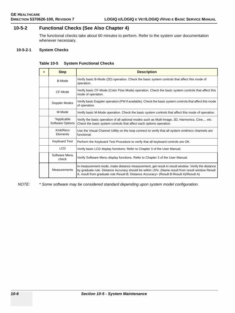
GE HEALTHCAREDIRECTION 5370626-100, REVISION 7 LOGIQ E/LOGIQ E VET/LOGIQ I/VIVID E BASIC SERVICE MANUAL
10-6 Section 10-5 - System Maintenance
10-5-2 Functional Checks (See Also Chapter 4)The functional checks take about 60 minutes to perform. Refer to the system user documentation whenever necessary.
10-5-2-1 System Checks
NOTE: * Some software may be considered standard depending upon system model configuration.
Table 10-5 System Functional Checks
÷ Step Description
B-Mode Verify basic B-Mode (2D) operation. Check the basic system controls that affect this mode of operation.
CF-Mode Verify basic CF-Mode (Color Flow Mode) operation. Check the basic system controls that affect this mode of operation.
Doppler Modes Verify basic Doppler operation (PW if available). Check the basic system controls that affect this mode of operation.
M-Mode Verify basic M-Mode operation. Check the basic system controls that affect this mode of operation.
*Applicable Software Options
Verify the basic operation of all optional modes such as Multi-Image, 3D, Harmonics, Cine,... etc. Check the basic system controls that affect each options operation.
Xmit/Recv Elements
Use the Visual Channel Utility on the loop connect to verify that all system xmit/recv channels are functional.
Keyboard Test Perform the Keyboard Test Procedure to verify that all keyboard controls are OK.
LCD Verify basic LCD display functions. Refer to Chapter 3 of the User Manual.
Software Menu check Verify Software Menu display functions. Refer to Chapter 3 of the User Manual.
MeasurementsIn measurement mode, make distance measurement, get result in result window. Verify the distance by graduate rule. Distance Accuracy should be within ±5%. (Name result from result window Result A, result from graduate rule Result B; Distance Accuracy= (Result B-Result A)/Result A)
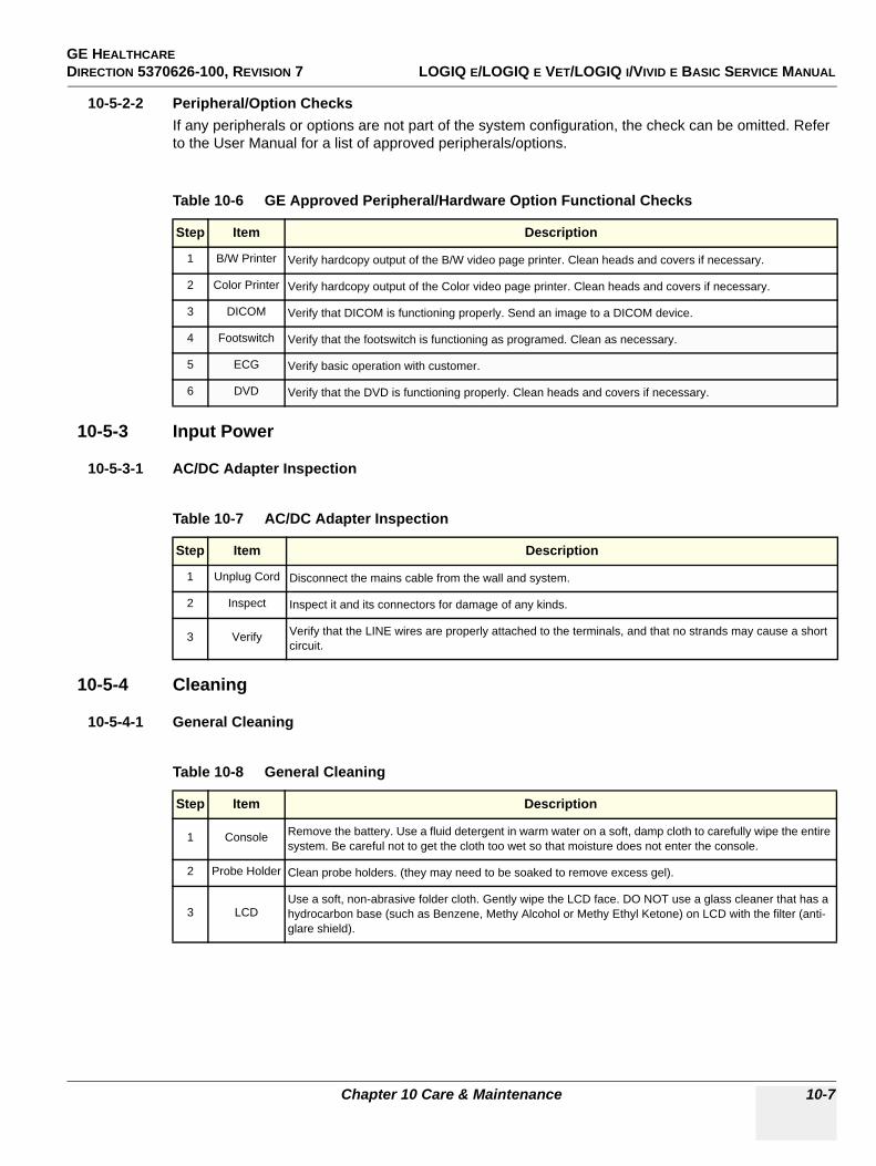
GE HEALTHCAREDIRECTION 5370626-100, REVISION 7 LOGIQ E/LOGIQ E VET/LOGIQ I/VIVID E BASIC SERVICE MANUAL
Chapter 10 Care & Maintenance 10-7
10-5-2-2 Peripheral/Option ChecksIf any peripherals or options are not part of the system configuration, the check can be omitted. Refer to the User Manual for a list of approved peripherals/options.
10-5-3 Input Power
10-5-3-1 AC/DC Adapter Inspection
10-5-4 Cleaning
10-5-4-1 General Cleaning
Table 10-6 GE Approved Peripheral/Hardware Option Functional Checks
Step Item Description
1 B/W Printer Verify hardcopy output of the B/W video page printer. Clean heads and covers if necessary.
2 Color Printer Verify hardcopy output of the Color video page printer. Clean heads and covers if necessary.
3 DICOM Verify that DICOM is functioning properly. Send an image to a DICOM device.
4 Footswitch Verify that the footswitch is functioning as programed. Clean as necessary.
5 ECG Verify basic operation with customer.
6 DVD Verify that the DVD is functioning properly. Clean heads and covers if necessary.
Table 10-7 AC/DC Adapter Inspection
Step Item Description
1 Unplug Cord Disconnect the mains cable from the wall and system.
2 Inspect Inspect it and its connectors for damage of any kinds.
3 Verify Verify that the LINE wires are properly attached to the terminals, and that no strands may cause a short circuit.
Table 10-8 General Cleaning
Step Item Description
1 Console Remove the battery. Use a fluid detergent in warm water on a soft, damp cloth to carefully wipe the entire system. Be careful not to get the cloth too wet so that moisture does not enter the console.
2 Probe Holder Clean probe holders. (they may need to be soaked to remove excess gel).
3 LCDUse a soft, non-abrasive folder cloth. Gently wipe the LCD face. DO NOT use a glass cleaner that has a hydrocarbon base (such as Benzene, Methy Alcohol or Methy Ethyl Ketone) on LCD with the filter (anti-glare shield).
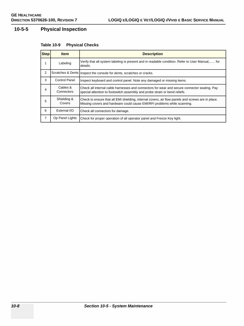
GE HEALTHCAREDIRECTION 5370626-100, REVISION 7 LOGIQ E/LOGIQ E VET/LOGIQ I/VIVID E BASIC SERVICE MANUAL
10-8 Section 10-5 - System Maintenance
10-5-5 Physical Inspection
Table 10-9 Physical Checks
Step Item Description
1 Labeling Verify that all system labeling is present and in readable condition. Refer to User Manual,...... for details.
2 Scratches & Dents Inspect the console for dents, scratches or cracks.
3 Control Panel Inspect keyboard and control panel. Note any damaged or missing items.
4 Cables & Connectors
Check all internal cable harnesses and connectors for wear and secure connector seating. Pay special attention to footswitch assembly and probe strain or bend reliefs.
5 Shielding & Covers
Check to ensure that all EMI shielding, internal covers, air flow panels and screws are in place. Missing covers and hardware could cause EMI/RFI problems while scanning.
6 External I/O Check all connectors for damage.
7 Op Panel Lights Check for proper operation of all operator panel and Freeze Key light.
GE HEALTHCAREDIRECTION 5370626-100, REVISION 7 LOGIQ E/LOGIQ E VET/LOGIQ I/VIVID E BASIC SERVICE MANUAL
Chapter 10 Care & Maintenance 10-9
10-5-6 Optional Diagnostic ChecksOptionally you can access the diagnostic software as described in Chapter 5 or 7. View the error logs and run desired diagnostics.
10-5-6-1 View the Logs
1.) Review the system error log for any problems.2.) Check the temperature log to see if there are any trends that could cause problems in the future.3.) Check the Configuration Log; update if needed.
10-5-7 Probe Maintenance
10-5-7-1 Probe Related Checks
10-5-7-2 Basic Probe CareThe system user manuals and various probe handling cards provide a complete description of probe care, maintenance, cleaning and disinfection. Ensure that you are completely familiar with the proper care of GE probes.
Ultrasound probes can be easily damaged by improper handling. See the User Manual and probe care cards for more details. Failure to follow these precautions can result in serious injury and equipment damage. Failure to properly handle or maintain a probe may also void its warranty.
Any evidence of wear indicates the probe cannot be used.
Do a visual check of the probe pins and system sockets before plugging in a probe.
10-5-7-3 Basic Probe CleaningRefer to the User’s Manual for details on probe cleaning.
NOTE: To help protect yourself from blood borne diseases, wear approved disposable gloves. These are made of nitrile derived from vegetable starch to prevent allergic latex reactions.
NOTE: Failure to follow the prescribed cleaning or disinfection procedures will void the probe’s warranty. DO NOT soak or wipe the lens with any product not listed in the User Manual. Doing so could result in irreparable damage to the probe. Follow care instructions that came with the probe.
NOTE: Disinfect a defective probe before you return it. Be sure to tag the probe as being disinfected.
Table 10-10 Probe Related Checks
Step Item Description
1 Probe Holder Clean probe holders (they may need to be soaked to remove excess gel).
2 Probes Thoroughly check the system probe connectors and remove dust from inside the connector sockets if necessary. Visually check for bent, damaged or missing pins
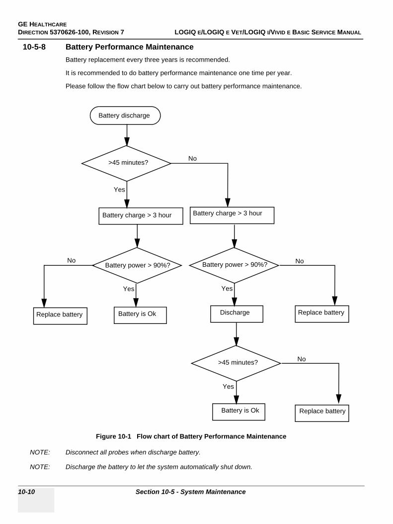
GE HEALTHCAREDIRECTION 5370626-100, REVISION 7 LOGIQ E/LOGIQ E VET/LOGIQ I/VIVID E BASIC SERVICE MANUAL
10-10 Section 10-5 - System Maintenance
10-5-8 Battery Performance MaintenanceBattery replacement every three years is recommended.
It is recommended to do battery performance maintenance one time per year.
Please follow the flow chart below to carry out battery performance maintenance.
NOTE: Disconnect all probes when discharge battery.
NOTE: Discharge the battery to let the system automatically shut down.
Figure 10-1 Flow chart of Battery Performance Maintenance
Battery discharge
Battery charge > 3 hour
Yes
No
Battery power > 90%?
Battery charge > 3 hour
Battery power > 90%? No
Battery is Ok
YesYes
Discharge Replace battery
No
Yes
Battery is Ok Replace battery
>45 minutes?
Replace battery
>45 minutes?
No
GE HEALTHCAREDIRECTION 5370626-100, REVISION 7 LOGIQ E/LOGIQ E VET/LOGIQ I/VIVID E BASIC SERVICE MANUAL
Chapter 10 Care & Maintenance 10-11
Section 10-6Electrical Safety Tests
10-6-1 Safety Test OverviewThe electrical safety tests in this section are based on and conform to IEC 60601-1 Medical Equipment Safety Standards. They are intended for the electrical safety evaluation of cord-connected, electrically operated, patient care equipment. If additional information is needed, refer to the IEC 60601-1 documents.
Test the system, peripherals and probes for leakage current. Excessive leakage current can cause injury or death in sensitive patients. High leakage current can also indicate degradation of insulation and a potential for electrical failure. Do not use probes or equipment having excessive leakage current.
To minimize the risk that a probe may shock someone the customer should:
• Not use a probe that is cracked or damaged in any way• Check probe leakage current:
* Based on your facilities QA program for surface probes* Based on your facilities QA program for endocavitary probes* whenever probe damage is suspected
WARNINGWARNING THE USER MUST ENSURE THAT THE SAFETY INSPECTIONS ARE PERFORMED AT LEAST EVERY 6 MONTHS ACCORDING TO THE REQUIREMENTS OF THE PATIENT SAFETY STANDARD IEC-EN 60601-1. ONLY TRAINED PERSONS ARE ALLOWED TO PERFORM THE SAFETY INSPECTIONS MENTIONED ABOVE.
CAUTION To avoid electrical shock, the unit under test must not be connected to other electrical equipment. The unit under test must not be contacted by users or patients while performing these tests.
CAUTION Possible risk of infection. Do not handle soiled or contaminated probes and other components that have been in patient contact. Follow appropriate cleaning and disinfecting procedures before handling the equipment.

GE HEALTHCAREDIRECTION 5370626-100, REVISION 7 LOGIQ E/LOGIQ E VET/LOGIQ I/VIVID E BASIC SERVICE MANUAL
10-12 Section 10-6 - Electrical Safety Tests
10-6-2 GEMS Leakage Current LimitsThe following limits are summarized for IEC 60601-1 Medical Equipment Safety Standards. These limits are GEMS standards and in some cases are lower than the above standards listed.
NOTE: *Mains Applied refers to the sink leakage test where mains (supply) voltage is applied to the part to determine the amount of current that will pass (or sink) to ground if a patient contacted mains voltage.
The following tests are performed at the factory and should be performed at the site. These tests are: chassis leakage current, and probe leakage current. All measurements are made with an electrical safety analyzer which should be calibrated and compliant with AAMI/ESI 1993 or IEC 60601 or AS/NZS 3551.
Table 10-11 Chassis Leakage Current Limits—Accessible Metal Surfaces
Country Normal Condition Open Ground Reverse Polarity Open Neutral
All (Except USA & Canada)
0.1 mA 0.5 mA 0.5 mA 0.5 mA
USA & Canada 0.1 mA 0.3 mA 0.3 mA 0.3 mA
Table 10-12 Type BF Applied Part Leakage Current Limits - Probes surface
CountryNormal
Condition Open Ground Reverse Polarity Open Neutral *Mains Applied
All 0.1 mA 0.5 mA 0.5 mA 0.5 mA 5.0 mA
Table 10-13 Type CF Applied Part Leakage Current Limits - ECG Connections
Country Normal Condition Open Ground Reverse Polarity Open Neutral *Mains Applied
All 0.01 mA 0.05 mA 0.05 mA 0.05 mA 0.05 mA
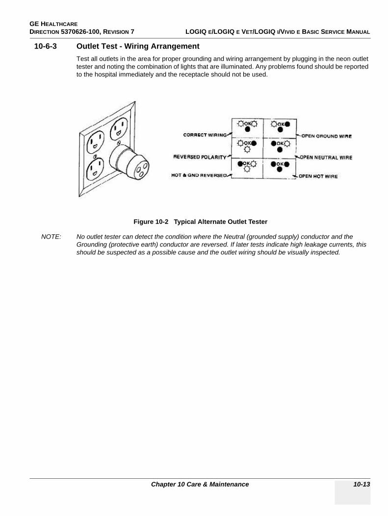
GE HEALTHCAREDIRECTION 5370626-100, REVISION 7 LOGIQ E/LOGIQ E VET/LOGIQ I/VIVID E BASIC SERVICE MANUAL
Chapter 10 Care & Maintenance 10-13
10-6-3 Outlet Test - Wiring Arrangement Test all outlets in the area for proper grounding and wiring arrangement by plugging in the neon outlet tester and noting the combination of lights that are illuminated. Any problems found should be reported to the hospital immediately and the receptacle should not be used.
NOTE: No outlet tester can detect the condition where the Neutral (grounded supply) conductor and the Grounding (protective earth) conductor are reversed. If later tests indicate high leakage currents, this should be suspected as a possible cause and the outlet wiring should be visually inspected.
Figure 10-2 Typical Alternate Outlet Tester
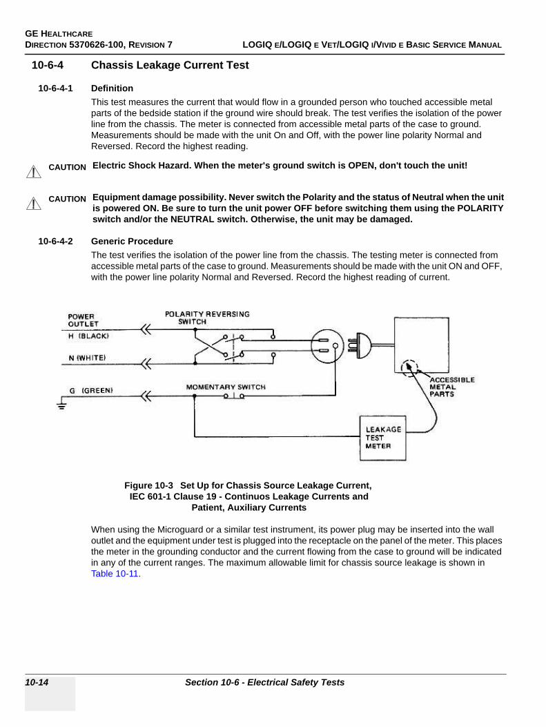
GE HEALTHCAREDIRECTION 5370626-100, REVISION 7 LOGIQ E/LOGIQ E VET/LOGIQ I/VIVID E BASIC SERVICE MANUAL
10-14 Section 10-6 - Electrical Safety Tests
10-6-4 Chassis Leakage Current Test
10-6-4-1 DefinitionThis test measures the current that would flow in a grounded person who touched accessible metal parts of the bedside station if the ground wire should break. The test verifies the isolation of the power line from the chassis. The meter is connected from accessible metal parts of the case to ground. Measurements should be made with the unit On and Off, with the power line polarity Normal and Reversed. Record the highest reading.
10-6-4-2 Generic ProcedureThe test verifies the isolation of the power line from the chassis. The testing meter is connected from accessible metal parts of the case to ground. Measurements should be made with the unit ON and OFF, with the power line polarity Normal and Reversed. Record the highest reading of current.
When using the Microguard or a similar test instrument, its power plug may be inserted into the wall outlet and the equipment under test is plugged into the receptacle on the panel of the meter. This places the meter in the grounding conductor and the current flowing from the case to ground will be indicated in any of the current ranges. The maximum allowable limit for chassis source leakage is shown in Table 10-11.
CAUTION Electric Shock Hazard. When the meter's ground switch is OPEN, don't touch the unit!
CAUTION Equipment damage possibility. Never switch the Polarity and the status of Neutral when the unit is powered ON. Be sure to turn the unit power OFF before switching them using the POLARITY switch and/or the NEUTRAL switch. Otherwise, the unit may be damaged.
Figure 10-3 Set Up for Chassis Source Leakage Current, IEC 601-1 Clause 19 - Continuos Leakage Currents and
Patient, Auxiliary Currents
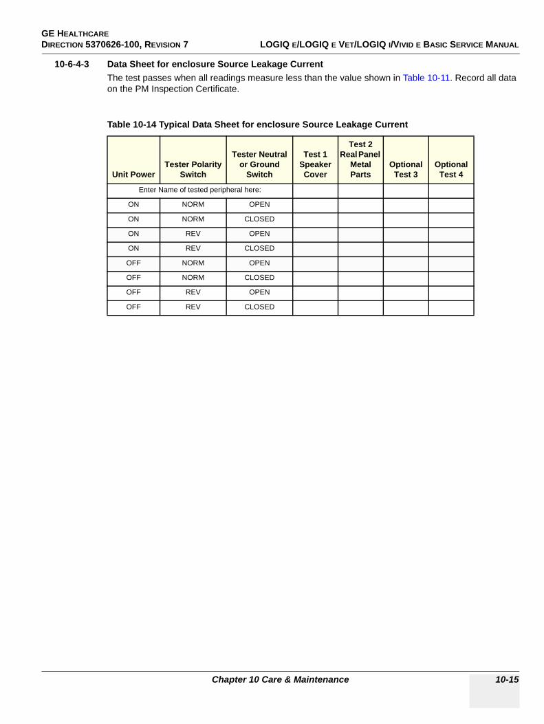
GE HEALTHCAREDIRECTION 5370626-100, REVISION 7 LOGIQ E/LOGIQ E VET/LOGIQ I/VIVID E BASIC SERVICE MANUAL
Chapter 10 Care & Maintenance 10-15
10-6-4-3 Data Sheet for enclosure Source Leakage CurrentThe test passes when all readings measure less than the value shown in Table 10-11. Record all data on the PM Inspection Certificate.
Table 10-14 Typical Data Sheet for enclosure Source Leakage Current
Unit PowerTester Polarity
Switch
Tester Neutral or Ground
Switch
Test 1 Speaker Cover
Test 2 Real Panel
Metal Parts
Optional Test 3
Optional Test 4
Enter Name of tested peripheral here:
ON NORM OPEN
ON NORM CLOSED
ON REV OPEN
ON REV CLOSED
OFF NORM OPEN
OFF NORM CLOSED
OFF REV OPEN
OFF REV CLOSED
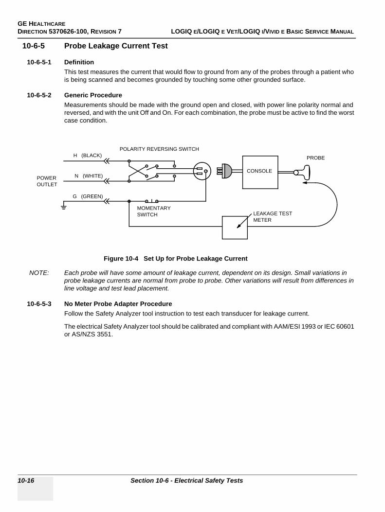
GE HEALTHCAREDIRECTION 5370626-100, REVISION 7 LOGIQ E/LOGIQ E VET/LOGIQ I/VIVID E BASIC SERVICE MANUAL
10-16 Section 10-6 - Electrical Safety Tests
10-6-5 Probe Leakage Current Test
10-6-5-1 DefinitionThis test measures the current that would flow to ground from any of the probes through a patient who is being scanned and becomes grounded by touching some other grounded surface.
10-6-5-2 Generic ProcedureMeasurements should be made with the ground open and closed, with power line polarity normal and reversed, and with the unit Off and On. For each combination, the probe must be active to find the worst case condition.
NOTE: Each probe will have some amount of leakage current, dependent on its design. Small variations in probe leakage currents are normal from probe to probe. Other variations will result from differences in line voltage and test lead placement.
10-6-5-3 No Meter Probe Adapter ProcedureFollow the Safety Analyzer tool instruction to test each transducer for leakage current.
The electrical Safety Analyzer tool should be calibrated and compliant with AAM/ESI 1993 or IEC 60601 or AS/NZS 3551.
Figure 10-4 Set Up for Probe Leakage Current
POWEROUTLET
H (BLACK)POLARITY REVERSING SWITCH
MOMENTARYSWITCH
N (WHITE)
G (GREEN)
LEAKAGE TESTMETER
CONSOLE
PROBE
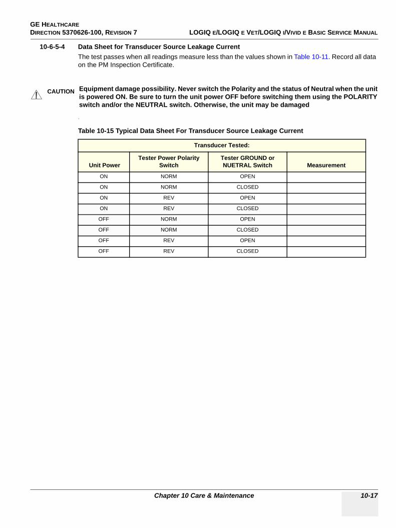
GE HEALTHCAREDIRECTION 5370626-100, REVISION 7 LOGIQ E/LOGIQ E VET/LOGIQ I/VIVID E BASIC SERVICE MANUAL
Chapter 10 Care & Maintenance 10-17
10-6-5-4 Data Sheet for Transducer Source Leakage CurrentThe test passes when all readings measure less than the values shown in Table 10-11. Record all data on the PM Inspection Certificate.
.
CAUTION Equipment damage possibility. Never switch the Polarity and the status of Neutral when the unit is powered ON. Be sure to turn the unit power OFF before switching them using the POLARITY switch and/or the NEUTRAL switch. Otherwise, the unit may be damaged
Table 10-15 Typical Data Sheet For Transducer Source Leakage Current
Transducer Tested:
Unit PowerTester Power Polarity
SwitchTester GROUND or NUETRAL Switch Measurement
ON NORM OPEN
ON NORM CLOSED
ON REV OPEN
ON REV CLOSED
OFF NORM OPEN
OFF NORM CLOSED
OFF REV OPEN
OFF REV CLOSED
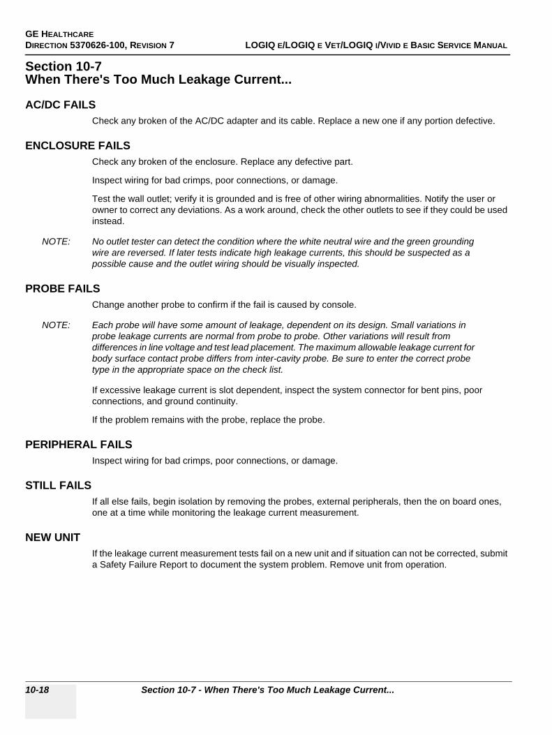
GE HEALTHCAREDIRECTION 5370626-100, REVISION 7 LOGIQ E/LOGIQ E VET/LOGIQ I/VIVID E BASIC SERVICE MANUAL
10-18 Section 10-7 - When There's Too Much Leakage Current...
Section 10-7When There's Too Much Leakage Current...
AC/DC FAILSCheck any broken of the AC/DC adapter and its cable. Replace a new one if any portion defective.
ENCLOSURE FAILSCheck any broken of the enclosure. Replace any defective part.
Inspect wiring for bad crimps, poor connections, or damage.
Test the wall outlet; verify it is grounded and is free of other wiring abnormalities. Notify the user or owner to correct any deviations. As a work around, check the other outlets to see if they could be used instead.
NOTE: No outlet tester can detect the condition where the white neutral wire and the green grounding wire are reversed. If later tests indicate high leakage currents, this should be suspected as a possible cause and the outlet wiring should be visually inspected.
PROBE FAILSChange another probe to confirm if the fail is caused by console.
NOTE: Each probe will have some amount of leakage, dependent on its design. Small variations in probe leakage currents are normal from probe to probe. Other variations will result from differences in line voltage and test lead placement. The maximum allowable leakage current for body surface contact probe differs from inter-cavity probe. Be sure to enter the correct probe type in the appropriate space on the check list.
If excessive leakage current is slot dependent, inspect the system connector for bent pins, poor connections, and ground continuity.
If the problem remains with the probe, replace the probe.
PERIPHERAL FAILSInspect wiring for bad crimps, poor connections, or damage.
STILL FAILSIf all else fails, begin isolation by removing the probes, external peripherals, then the on board ones, one at a time while monitoring the leakage current measurement.
NEW UNITIf the leakage current measurement tests fail on a new unit and if situation can not be corrected, submit a Safety Failure Report to document the system problem. Remove unit from operation.
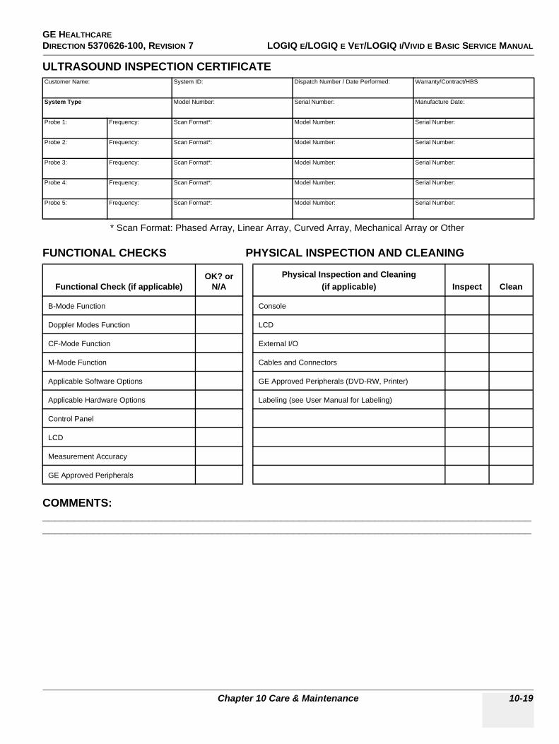
GE HEALTHCAREDIRECTION 5370626-100, REVISION 7 LOGIQ E/LOGIQ E VET/LOGIQ I/VIVID E BASIC SERVICE MANUAL
Chapter 10 Care & Maintenance 10-19
ULTRASOUND INSPECTION CERTIFICATE
* Scan Format: Phased Array, Linear Array, Curved Array, Mechanical Array or Other
FUNCTIONAL CHECKS PHYSICAL INSPECTION AND CLEANING
COMMENTS: ____________________________________________________________________________________________________________________________________________________________
Customer Name: System ID: Dispatch Number / Date Performed: Warranty/Contract/HBS
System Type Model Number: Serial Number: Manufacture Date:
Probe 1: Frequency: Scan Format*: Model Number: Serial Number:
Probe 2: Frequency: Scan Format*: Model Number: Serial Number:
Probe 3: Frequency: Scan Format*: Model Number: Serial Number:
Probe 4: Frequency: Scan Format*: Model Number: Serial Number:
Probe 5: Frequency: Scan Format*: Model Number: Serial Number:
Functional Check (if applicable)OK? or
N/APhysical Inspection and Cleaning
(if applicable) Inspect Clean
B-Mode Function Console
Doppler Modes Function LCD
CF-Mode Function External I/O
M-Mode Function Cables and Connectors
Applicable Software Options GE Approved Peripherals (DVD-RW, Printer)
Applicable Hardware Options Labeling (see User Manual for Labeling)
Control Panel
LCD
Measurement Accuracy
GE Approved Peripherals
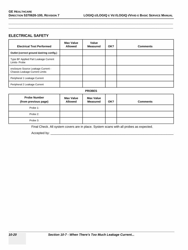
GE HEALTHCAREDIRECTION 5370626-100, REVISION 7 LOGIQ E/LOGIQ E VET/LOGIQ I/VIVID E BASIC SERVICE MANUAL
10-20 Section 10-7 - When There's Too Much Leakage Current...
____________________________________________________________________________________________________________________________________________________________
ELECTRICAL SAFETY
Final Check. All system covers are in place. System scans with all probes as expected.
Accepted by: ______________________________________________________________________
Electrical Test PerformedMax Value Allowed
Value Measured OK? Comments
Outlet (correct ground &wiring config.)
Type BF Applied Part Leakage Current Limits- Probe
enclosure Source Leakage Current - Chassis Leakage Current Limits
Peripheral 1 Leakage Current
Peripheral 2 Leakage Current
PROBES
Probe Number (from previous page)
Max Value Allowed
Max Value Measured OK? Comments
Probe 1:
Probe 2:
Probe 3:

GE HEALTHCAREDIRECTION 5370626-100, REVISION 7 LOGIQ E/LOGIQ E VET/LOGIQ I/VIVID E BASIC SERVICE MANUAL
Chapter 10 Care & Maintenance 10-21
This page was intentionally left blank.
GE HEALTHCAREDIRECTION 5370626-100, REVISION 7 LOGIQ E/LOGIQ E VET/LOGIQ I/VIVID E BASIC SERVICE MANUAL
10-22 Section 10-7 - When There's Too Much Leakage Current...
GE HEALTHCARE DIRECTION 5370626-100, REVISION 7 LOGIQ E/LOGIQ E VET/LOGIQ I/VIVID E BASIC SERVICE MANUAL
Index 1
INDEXA,BAbbreviations, 9-1Archiving Images
Move, 4-31Backup
Patient Database, 4-28Preset Configurations, 4-28
Basic MeasurementsFunctional Checks, 4-25
Body patterndisplay location, 4-9
Boot Up, 3-9
CCaps lock
display location, 4-9CE Compliance, 1-18Cine gauge
display location, 4-9Color Mode
Overview, 4-20Configuration, 5-19Connectivity
Worksheet, 3-28Contact Information, 1-19Control Panel, 4-7Conventions
Conventions Used in Book, 1-5Customer Assistance, 1-19CW Doppler
activating, 4-24exiting, 4-24
DDangerous Procedure Warnings, 1-16Date/Time
display location, 4-9Depth scale
display location, 4-9Diagnostics, 5-17DICOM Network Function, 2-9
EElectrical
requirements, 2-2Electrical Safety, 1-12Electrostatic Discharge Warning, 1-18
EMI, 1-18ESD, 1-18Exam study
display location, 4-9
FFocal zone
display location, 4-9Functional Checks
Basic Measurements, 4-25Control Panel, 4-7Image Management, 4-27Monitor Display, 4-9Peripherals, 4-37Probes/Connector Usage, 4-25
GGathering Trouble Data, 7-2General Cleaning, 10-7Gray/color bar
display location, 4-9
HHazard Icons, 1-6Hospital name
display location, 4-9Human Safety, 1-11
IImage Management
Functional Checks, 4-27Image preview
display location, 4-9Imaging parameters
display location, 4-9Inrush Current, 2-2, , 2-3Institution name
display location, 4-9
LLogs, 5-14LOTO, 1-16, , 4-6
GE HEALTHCAREDIRECTION 5370626-100, REVISION 7 LOGIQ E/LOGIQ E VET/LOGIQ I/VIVID E BASIC SERVICE MANUAL
Index 2
MMeasurement summary window
display location, 4-9Mechanical Safety, 1-11Media
Formatting, 4-28Models Covered, 1-3Monitor Display
Functioanl Checks, 4-9Monitor display
location, 4-9Move
Archiving Images, 4-31
OOperator identification
display location, 4-9
PP4 Key Function, 7-4, , 7-6Patient identification
display location, 4-9Patient name
display location, 4-9PC Diagnostics, 7-13
Hard Drive Tests, 7-13Keyboard Test, 7-14Memory Tests, 7-13
PC Diagnostics (Interactive Tests), 7-14Peripherals
Functional Checks, 4-37Power On, 3-9Power Requirements, 2-2
electrical, 2-2stability, 2-3
Power Stability Requirements, 2-3Probe Connector Cleaning, 10-9Probe identifier
display location, 4-9Probe orientation marker
display location, 4-9Probes/Connector Usage
Functional Checks, 4-25
RRequired Features, 2-7Restore
Patient Database, 4-30Preset Configurations, 4-30
SSafety Considerations, 1-11Screen Captures, 7-6System Maintenance, 10-5System Manufacturer, 1-20System messages
display location, 4-9
TTGC
display location, 4-9Touch Panel
Functional Checks, 4-7Trouble Image with Logs, 7-3Troubleshooting
Gathering Trouble Data, 7-2Screen Captures, 7-6Trouble Image with Logs, 7-3Vital System Information, 7-2
UUtilities, 5-19
WWarnings and Cautions, 1-11


© 2004 to 2011, General Electric Company.GE Medical Systems, a General Electric Company, going to market as GE Healthcare.3200 N. Grandview BoulevardWaukesha, Wisconsin 53149USA
www.gehealthcare.com
Related Documents