DS858 October 19, 2011 www.xilinx.com 1 Product Specification © Copyright 2011 Xilinx, Inc. Xilinx, the Xilinx logo, Artix, ISE, Kintex, Spartan, Virtex, Zynq, and other designated brands included herein are trademarks of Xilinx in the United States and other countries. MATLAB is a registered trademark of The MathWorks, Inc. ARM is a registered trademark of ARM in the EU and other countries. The AMBA trademark is a registered trademark of ARM Limited. All other trademarks are the property of their respective owners. Introduction The Xilinx LogiCORE™ IP v5.0 core implements a generalized coordinate rotational digital computer (CORDIC) algorithm. Features • AXI4-Stream-compliant Interfaces • Functional configurations • Vector rotation (polar to rectangular) • Vector translation (rectangular to polar) • Sin and Cos • Sinh and Cosh • Atan and Atanh • Square root • Optional coarse rotation module to extend the range of CORDIC from the first quadrant (+Pi/4 to - Pi/4 Radians) to the full circle • Optional amplitude compensation scaling module to compensate for the output amplitude scale factor of the CORDIC algorithm • Output rounding modes: Truncation, Round to Pos Infinity, Round to Pos/Neg Infinity, and Round to Nearest Even • Word serial architectural configuration for small area • Parallel architectural configuration for high throughput • Control of the internal add-sub precision • Control of the number of add-sub iterations • X and Y data formats: Signed Fraction, Unsigned Fraction, and Unsigned Integer • Phase data formats: Radian, Pi Radian • Fully synchronous design using a single clock • For use with Xilinx CORE Generator™ and Xilinx System Generator for DSP, v13.3. LogiCORE IP CORDIC v5.0 DS858 October 19, 2011 Product Specification LogiCORE IP Facts Table Core Specifics Supported Device Family (1) Virtex-7 and Kintex-7, Artix™-7, Zynq™-7000, Virtex-6, Spartan-6 Supported User Interfaces AXI4-Stream Provided with Core Documentation Product Specification Design Files Netlist Example Design Not Provided Test Bench VHDL Constraints File N/A Simulation Model Verilog and VHDL Tested Design Tools Design Entry Tools CORE Generator tool 13.3 System Generator for DSP 13.3 Simulation (2) Mentor Graphics ModelSim Cadence Incisive Enterprise Simulator (IES) Synopsys VCS and VCS MX ISim Synthesis Tools N/A Support Provided by Xilinx, Inc. 1. For a complete listing of supported devices, see the release notes for this core. 2. For the supported version of the tools, see the ISE Design Suite 13: Release Notes Guide

Welcome message from author
This document is posted to help you gain knowledge. Please leave a comment to let me know what you think about it! Share it to your friends and learn new things together.
Transcript
DS858 October 19, 2011 www.xilinx.com 1Product Specification
© Copyright 2011 Xilinx, Inc. Xilinx, the Xilinx logo, Artix, ISE, Kintex, Spartan, Virtex, Zynq, and other designated brands included herein are trademarks of Xilinx in the United States and other countries. MATLAB is a registered trademark of The MathWorks, Inc. ARM is a registered trademark of ARM in the EU and other countries. The AMBA trademark is a registered trademark of ARM Limited. All other trademarks are the property of their respective owners.
IntroductionThe Xilinx LogiCORE™ IP v5.0 core implements ageneralized coordinate rotational digital computer(CORDIC) algorithm.
Features• AXI4-Stream-compliant Interfaces
• Functional configurations
• Vector rotation (polar to rectangular)• Vector translation (rectangular to polar)• Sin and Cos• Sinh and Cosh• Atan and Atanh• Square root
• Optional coarse rotation module to extend the range of CORDIC from the first quadrant (+Pi/4 to - Pi/4 Radians) to the full circle
• Optional amplitude compensation scaling module to compensate for the output amplitude scale factor of the CORDIC algorithm
• Output rounding modes: Truncation, Round to Pos Infinity, Round to Pos/Neg Infinity, and Round to Nearest Even
• Word serial architectural configuration for small area
• Parallel architectural configuration for high throughput
• Control of the internal add-sub precision
• Control of the number of add-sub iterations
• X and Y data formats: Signed Fraction, Unsigned Fraction, and Unsigned Integer
• Phase data formats: Radian, Pi Radian
• Fully synchronous design using a single clock
• For use with Xilinx CORE Generator™ and Xilinx System Generator for DSP, v13.3.
LogiCORE IP CORDIC v5.0
DS858 October 19, 2011 Product Specification
LogiCORE IP Facts Table
Core Specifics
Supported Device Family(1)
Virtex-7 and Kintex-7, Artix™-7, Zynq™-7000,Virtex-6, Spartan-6
Supported User Interfaces AXI4-Stream
Provided with Core
Documentation Product Specification
Design Files Netlist
Example Design Not Provided
Test Bench VHDL
Constraints File N/A
Simulation Model Verilog and VHDL
Tested Design Tools
Design Entry Tools
CORE Generator tool 13.3System Generator for DSP 13.3
Simulation(2)
Mentor Graphics ModelSimCadence Incisive Enterprise Simulator (IES)
Synopsys VCS and VCS MXISim
Synthesis Tools N/A
Support
Provided by Xilinx, Inc.
1. For a complete listing of supported devices, see the release notes for this core.
2. For the supported version of the tools, see the ISE Design Suite 13: Release Notes Guide

DS858 October 19, 2011 www.xilinx.com 2Product Specification
LogiCORE IP CORDIC v5.0
General DescriptionThe CORDIC core implements a generalized coordinate rotational digital computer (CORDIC) algorithm, initiallydeveloped by Volder[1] to iteratively solve trigonometric equations, and later generalized by Walther[2] to solve abroader range of equations, including the hyperbolic and square root equations. The CORDIC core implements thefollowing equation types:
• Rectangular <-> Polar Conversion
• Trigonometric
• Hyperbolic
• Square Root
Two architectural configurations are available for the CORDIC core:
• A fully parallel configuration with single-cycle data throughput at the expense of silicon area
• A word serial implementation with multiple-cycle throughput but occupying a small silicon area
A coarse rotation is performed to rotate the input sample from the full circle into the first quadrant. (The coarserotation stage is required as the CORDIC algorithm is only valid over the first quadrant). An inverse coarse rotationstage rotates the output sample into the correct quadrant.
The CORDIC algorithm introduces a scale factor to the amplitude of the result, and the CORDIC core provides theoption of automatically compensating for the CORDIC scale factor.
The CORDIC algorithm can be used to solve several functions as described above. These functions take differentcombinations of cartesian and polar operands. The operands X_IN and Y_IN are input using theS_AXIS_CARTESIAN channel and the PHASE_IN operand is input using the S_AXIS_PHASE input.
A block diagram of the CORDIC core is presented in Figure 1.
X-Ref Target - Figure 1
Figure 1: CORDIC Symbol and Pinout

DS858 October 19, 2011 www.xilinx.com 3Product Specification
LogiCORE IP CORDIC v5.0
Interface Pins
Note: All AXI4-Stream port names are lower case; however, for readability, upper case is used in this document when referring to port name suffixes, such as TDATA or TLAST.
Width constants A thru F are arbitrary values, determined by GUI or XCO parameters. Many pins are optional.Input channels are absent if the function selected does not require the operands carried by the channel in question.For example, the Square Root function does not require PHASE_IN, so S_AXIS_PHASE is not present for thisfunction.
Table 1: Core Pinout
Port Name Direction Description
aclk IN Clock.Active rising edge.
aclken IN Clock Enable. Active high
aresetn IN Synchronous Reset. Active low. aresetn must be active for at least 2 clock cycles when asserted.
s_axis_cartesian_tvalid IN Handshake signal for channel S_AXIS_CARTESIAN. See AXI4-Stream Considerations.
s_axis_cartesian_tready OUT Handshake signal for channel S_AXIS_CARTESIAN. See AXI4-Stream Considerations.
s_axis_cartesian_tdata[A-1:0] IN Depending on Functional Configuration, this port will have one or two subfields; X_IN and Y_IN. These are the cartesian operands. Each subfield is Input_Width bits wide, padded to the next byte width before being concatenated. See TDATA Packing.
s_axis_cartesian_tuser[B-1:0] IN Data on this port will be delayed with the same latency as TDATA and appear on m_axis_dout_tuser. See AXI4-Stream Considerations.
s_axis_cartesian_tlast IN TLAST is not used by the core, but will be combined with s_axis_phasr_tlast, or passed untouched to m_axis_dout_tlast according to TLAST_Behavior &&& Check GUI field name.
s_axis_phase_tvalid IN Handshake signal for channel S_AXIS_PHASE. See AXI4-Stream Considerations.
s_axis_phase_tready OUT Handshake signal for channel S_AXIS_PHASE. See AXI4-Stream Considerations.
s_axis_phase_tdata[C-1:0] IN This port has one subfield, PHASE_IN. It is the polar operand. The subfield is Input_Width bits wide, padded to the next byte width.
s_axis_phase_tuser[D-1:0] IN Data on this port will be delayed with the same latency as TDATA and appear on m_axis_dout_tuser. See AXI4-Stream Considerations.
s_axis_phase_tlast IN TLAST is not used by the core, but will be combined with s_axis_cartesian_tlast, or passed untouched to m_axis_dout_tlast according to TLAST_Behavior &&& Check GUI field name.
m_axis_dout_tvalid OUT Handshake signal for channel M_AXIS_DOUT. See AXI4-Stream Considerations.
m_axis_dout_tready IN Handshake signal for channel M_AXIS_DOUT. See AXI4-Stream Considerations.
m_axis_dout_tdata[E-1:0] OUT Depending on Functional Configuration this port will contain the following subfields; X_OUT, Y_OUT, PHASE_OUT. Each subfield will be Output_Width bits wide, padded to the next byte width before concatenation.
m_axis_dout_tuser[F-1:0] OUT This port will contain the values input to s_axis_cartesian_tuser and/or s_axis_phase_tuser delayed by the same latency as for TDATA.
m_axis_dout_tlast OUT This port will output s_axis_cartesian_tlast, s_axis_phase_tlast or some combination of the two delayed by the same latency as for TDATA.

DS858 October 19, 2011 www.xilinx.com 4Product Specification
LogiCORE IP CORDIC v5.0
Data Inputs and Outputs
The set of data input ports and output TDATA subfields for a particular Functional Configuration are automaticallydetermined by the GUI, shown in Table 2.
CORE Generator GUI and ParametersThe CORDIC Graphical User Interface (GUI) contains three pages for configuring the core and two informationtabs.
Tab 1 & 2: IP Symbol and Implementation Details
The IP Symbol tab illustrates the core pinout.
The Implementation Details tab displays the core latency and resource usage. The block RAM andMultiplier/XtremeDSP Slice resources are only utilized when Compensation Scaling is selected.
Page 1
Used to configure the functional selection and architecture of the CORDIC core.
• Component Name: Used as the base name of the output files generated for the core. Names must begin with a letter and be composed from the following characters: a to z, 0 to 9, and “_.”
• Functional Selection: The functional selections available are Rotate, Sin and Cos, ArcTan, Square Root, Translate, Sinh and Cosh and ArcTanh. See the Functional Description section for more information on each of the supported functions. In general, X_IN, Y_IN, X_OUT and Y_OUT express signed binary numbers of 1QN format and PHASE_IN and PHASE_OUT express signed binary numbers of 2QN format. When Square Root is selected, two new data formats are available: Unsigned Integer and Unsigned Fraction. For details about CORDIC binary data formats, see Input/Output Data Representation.
• Architectural Configuration: Two architectural configurations are available for the CORDIC core, Parallel and Word Serial. See Architectural Configuration for more details.
• Pipelining Mode: The CORDIC core provides three pipelining modes: None, Optimal, and Maximum. The choice of pipelining mode is based on the selection of Functional Configuration and Architectural Configuration. Unavailable pipelining modes are greyed out in the GUI.
Table 2: Input/Output Subfields vs. Functional Configuration
S_AXIS_CARTESIAN S_AXIS_PHASE M_AXIS_DOUT
Function XIN YIN PHASE_IN XOUT YOUT PHASE_OUT
Rotate 1 1 1 1 1 0
Translate 1 1 0 1 0 1
Sin and Cos 0 0 1 1 1 0
ArcTan 1 1 0 0 0 1
Sinh and Cosh 0 0 1 1 1 0
ArcTanh 1 1 0 0 0 1
Square Root 1 0 0 1 0 0
Notes: 1. A ‘1’ indicates that the subfield (and parent channel) are present. A ‘0’ indicates that the subfield is absent. If all subfields of a
channel are absent, the channel is also absent. The X_IN operand, if present, is in the least significant bit positions of S_AXIS_CARTESIAN. SImilarly, X_OUT is in the least significant position of M_AXIS_DOUT, with Y_OUT in the next significant position and PHASE_OUT in the most significant position. Where one or more is missing, the remaining operands shift down in bit position. For example, for Translate with output_width of 8, XOUT is [7:0] and PHASE_OUT is [15:8] of M_AXIS_DOUT_TDATA.

DS858 October 19, 2011 www.xilinx.com 5Product Specification
LogiCORE IP CORDIC v5.0
• None: the CORDIC core is implemented without pipelining.
• Optimal: the CORDIC core is implemented with as many stages of pipelining as possible without using any additional LUTs.
• Maximum: the CORDIC core is implemented with a pipeline after every shift-add sub stage.
• Data Format: The CORDIC core provides three formats for expressing the X and Y components of data samples:
• Signed Fraction: Default setting. The X and Y inputs and outputs are expressed as fixed-point 2’s complement numbers with an integer width of 2 bits. Example: "11100000” represents the value -0.5.
• Unsigned Fraction: The X and Y inputs and outputs are expressed as unsigned fixed-point number with an integer with of 1 bit.Available only for Square Root functional configuration. Example: “11100000” represents the value +1.75.
• Unsigned Integer: The X and Y inputs and outputs express unsigned integers.Available only for Square Root functional configuration. Example: “11100000” represents the value +224.
• Phase Format: The CORDIC core provides two Phase Format options:
• Radians: The phase is expressed as a fixed-point 2’s complement numbers with an integer width of 3 bits, in radian units.Example: “01100000” represents the value 3.0 radians.
• Scaled Radians: The phase is expressed as fixed-point 2’s complement numbers with an integer width of 3 bits, with Pi-radian units. One scaled-radian equals Pi * 1 radians.Example: “11110000” represents the value -0.5 * Pi radians.
See Input/Output Data Representation for more information about CORDIC binary data formats.
• Input / Output Options: The CORDIC core provides four input / output common configuration options.
• Input Width: Input Width controls the widths of the input ports, X_IN, Y_IN and PHASE_IN. The Input Width can be configured in the range 8 to 48 bits.
• Register Inputs: Selects if the input signals X_IN, Y_IN, PHASE_IN are registered.
• Output Width: Output Width controls the widths of the output ports, X_OUT, Y_OUT, PHASE_OUT. The Output Width can be configured in the range 8 to 48 bits.
• Register Outputs: Selects if the output signals, X_OUT, Y_OUT, PHASE_OUT are registered.
• Round Mode: The CORDIC core provides four rounding modes. Table 3 illustrates the behavior of the different Rounding modes.
• Truncate: The X_OUT, Y_OUT, and PHASE_OUT outputs are truncated.
• Positive Infinity: The X_OUT, Y_OUT, and PHASE_OUT outputs are rounded such that 1/2 is rounded up (towards positive infinity). It is equivalent to the MATLAB function floor(x+0.5).
• Pos Neg Infinity: The outputs X_OUT, Y_OUT, and PHASE_OUT are rounded such that 1/2 is rounded up (towards positive infinity) and -1/2 is rounded down (towards negative infinity). It is equivalent to the MATLAB function round(x).
• Nearest Even: The X_OUT, Y_OUT, and PHASE_OUT outputs are rounded toward the nearest even number such that a 1/2 is rounded down and 3/2 is rounded up.
Table 3: Rounding Modes
Truncate Pos Neg Infinity Positive Infinity Nearest Even
1.50 1 2 2 2
1.00 1 1 1 1
0.50 0 1 1 0

DS858 October 19, 2011 www.xilinx.com 6Product Specification
LogiCORE IP CORDIC v5.0
• Advanced Configuration Parameters
• Iterations: Controls the number of internal add-sub iterations to perform.When Iterations is set to zero, the number of iterations performed is determined by the required accuracy of the output. By default, Iterations is set to zero, thus the number of iterations is automatically determined.
• Precision: Configures the internal precision of the add-sub iterations. When Precision is set to zero, internal precision is determined automatically based on the required accuracy of the output and the number of internal iterations. By default, Precision is set to zero, thus the internal precision is automatically determined. When Precision is set to (input width + output width + log2(output_width)) the output phase is precise to the full output width regardless of input magnitude. However, the output phase accuracy is still limited by the OQEIQ component of Output Quantization Error and by the number of Iterations of the CORDIC Micro-Rotation block.
• Coarse Rotation: Controls the instantiation of the coarse rotation module. Instantiation of the coarse rotation module is the default for the functional configurations: Vector rotation, Vector translation, Sin and Cos, and ArcTan. If Coarse Rotation is turned off for these functions, the input/output range is limited to the first quadrant (-Pi/4 to + Pi/4). Coarse rotation is not required for the Sinh and Cosh, ArcTanh, and Square Root configurations. The standard CORDIC algorithm operates over the first quadrant. Coarse Rotation extends the CORDIC operational range to the full circle by rotating the input sample into the first quadrant and inverse rotating the output sample back into the appropriate quadrant.
• Compensation Scaling: Controls the compensation scaling module used to compensate for CORDIC magnitude scaling. CORDIC magnitude scaling affects the Vector Rotation and Vector Translation functional configurations. It does not affect the Sin, Cos, Sinh, Cosh, ArcTan, ArcTanh and Square Root functional configurations. For the latter configurations, compensation scaling is set to No Scale Compensation. CORDIC magnitude scaling is a side effect of the CORDIC algorithm. The magnitude outputs, X and Y, are generated scaled by the CORDIC scale factor, Zn. The compensation scaling module compensates for the effect of CORDIC magnitude scaling by scaling the outputs, X and Y, by 1/Zn.
- No Scale Compensation: The outputs X and Y are not compensated and are generated, scaled by the ratio Zn.
- LUT Based: The outputs X and Y are compensated using a LUT-based Constant Coefficient Multiplier.
- BRAM: The outputs X and Y are compensated using a block RAM-based Constant Coefficient Multiplier.
- Embedded Multiplier: The outputs X and Y are compensated using the XtremeDSP™ Slice or embedded multiplier depending on the family of part chosen in the CORE Generator project options.
0.25 0 0 0 0
0.00 0 0 0 0
- 0.25 -1 0 0 0
- 0.50 -1 -1 0 -1
- 0.75 -1 -1 -1 -1
Table 3: Rounding Modes (Cont’d)
Truncate Pos Neg Infinity Positive Infinity Nearest Even
DS858 October 19, 2011 www.xilinx.com 7Product Specification
LogiCORE IP CORDIC v5.0
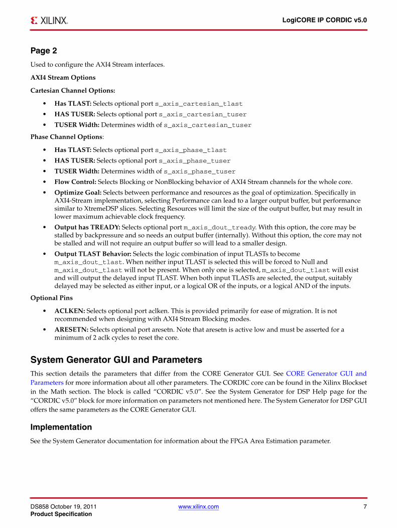
Page 2
Used to configure the AXI4 Stream interfaces.
AXI4 Stream Options
Cartesian Channel Options:
• Has TLAST: Selects optional port s_axis_cartesian_tlast
• HAS TUSER: Selects optional port s_axis_cartesian_tuser
• TUSER Width: Determines width of s_axis_cartesian_tuser
Phase Channel Options:
• Has TLAST: Selects optional port s_axis_phase_tlast
• HAS TUSER: Selects optional port s_axis_phase_tuser
• TUSER Width: Determines width of s_axis_phase_tuser
• Flow Control: Selects Blocking or NonBlocking behavior of AXI4 Stream channels for the whole core.
• Optimize Goal: Selects between performance and resources as the goal of optimization. Specifically in AXI4-Stream implementation, selecting Performance can lead to a larger output buffer, but performance similar to XtremeDSP slices. Selecting Resources will limit the size of the output buffer, but may result in lower maximum achievable clock frequency.
• Output has TREADY: Selects optional port m_axis_dout_tready. With this option, the core may be stalled by backpressure and so needs an output buffer (internally). Without this option, the core may not be stalled and will not require an output buffer so will lead to a smaller design.
• Output TLAST Behavior: Selects the logic combination of input TLASTs to become m_axis_dout_tlast. When neither input TLAST is selected this will be forced to Null and m_axis_dout_tlast will not be present. When only one is selected, m_axis_dout_tlast will exist and will output the delayed input TLAST. When both input TLASTs are selected, the output, suitably delayed may be selected as either input, or a logical OR of the inputs, or a logical AND of the inputs.
Optional Pins
• ACLKEN: Selects optional port aclken. This is provided primarily for ease of migration. It is not recommended when designing with AXI4 Stream Blocking modes.
• ARESETN: Selects optional port aresetn. Note that aresetn is active low and must be asserted for a minimum of 2 aclk cycles to reset the core.
System Generator GUI and ParametersThis section details the parameters that differ from the CORE Generator GUI. See CORE Generator GUI andParameters for more information about all other parameters. The CORDIC core can be found in the Xilinx Blocksetin the Math section. The block is called “CORDIC v5.0”. See the System Generator for DSP Help page for the“CORDIC v5.0” block for more information on parameters not mentioned here. The System Generator for DSP GUIoffers the same parameters as the CORE Generator GUI.
Implementation
See the System Generator documentation for information about the FPGA Area Estimation parameter.

DS858 October 19, 2011 www.xilinx.com 8Product Specification
LogiCORE IP CORDIC v5.0
XCO Parameters
Table 4 defines the mapping between GUI parameters and XCO parameters.
Demonstration Test Bench
When the core is generated using the Xilinx CORE Generator tool, a demonstration test bench is created. This is asimple VHDL test bench that exercise the core.
The demonstration test bench source code is one VHDL file: demo_tb/tb_<component_name>.vhd in theCORE Generator output directory. The source code is comprehensively commented.
Table 4: XCO Parameters
GUI Parameter Default Value XCO Values XCO Parameter
Component Name cordic_v5_0 Component_Name
Functional Selection Rotate Rotate, Translate, Sin_and_Cos, Sinh_and_Cosh, Arc_Tan, Arc_Tanh, Square_Root
Functional_Selection
Architectural Configuration Parallel Word_Serial, Parallel Architectural_Configuration
Pipelining Mode Maximum No_Pipelining, Optimal, Maximum Pipelining_Mode
Data Format SignedFraction SignedFraction, UnsignedFraction, UnsignedInteger
Data_Format
Phase Format Radians Radians, Scaled_Radians Phase_Format
Input Width 16 8 to 48 Input_Format
Output Width 16 8 to 48 Output_Format
Round Mode Truncate Truncate, Round_Pos_Inf, Round_Pos_Neg_Inf, Nearest_Even
Round_Mode
Iterations 0 0 to 48 Iterations
Precision 0 0 to 48 Precision
Coarse Rotation false false, true Coarse_Rotation
Compensation Scaling No_Scale_Compensation No_Scale_Compensation, LUT_based, BRAM, Embedded_Multiplier
Compensation_Scaling
Cartesian Has TLAST false false, true cartesian_has_tlast
Cartesian Has TUSER false false, true cartesian_has_tuser
Cartesian TUSER Width 1 1 to 64 cartesian_tuser_width
Phase Has TLAST false false, true phase_has_tlast
Phase Has TUSER false false, true phase_has_tuser
Phase TUSER Width 1 1 to 64 phase_tuser_width
Flow Control NonBlocking NonBlocking, Blocking flow_control
Optimize Goal Resources Resources, Performance optimize_goal
Output has TREADY false false, true out_tready
OutputTLAST Behavior Null Null, Pass_Cartesian_TLAST, Pass_Phase_TLAST, OR_all_TLASTs, AND_all_TLASTs
out_tlast_behv
ACLKEN false false, true ACLKEN
ARESETN false false, true ARESETN

DS858 October 19, 2011 www.xilinx.com 9Product Specification
LogiCORE IP CORDIC v5.0
Using the Demonstration Test Bench
The demonstration test bench instantiates the generated CORDIC core. Either the behavioral model or the netlistcan be simulated within the demonstration test bench.
• Behavioral model: Ensure that the CORE Generator project options are set to generate a behavioral model.
After generation, this creates a behavioral model wrapper named <component_name>.vhd. Compile this file intothe work library (see your simulator documentation for information on how to do this).
• Netlist: If the CORE Generator project options were set to generate a structural model, a VHDL or Verilog netlist named <component_name>.vhd or <component_name>.v was generated. If this option was not set, generate a netlist using the netgen program, for example:
netgen -sim -ofmt vhdl <component_name>.ngc <component_name>_netlist.vhd
Compile the netlist into the work library (see your simulator documentation for more information).
Compile the demonstration test bench into the work library. Then simulate the demonstration test bench. View thetest bench signals in the simulator waveform viewer to see the operations of the test bench.
Demonstration Test Bench in Detail
The demonstration test bench performs the following tasks:
• Instantiates the core
• Generates stimulus data sets for each input channel. Both sets are rotating phasors
• Generates a clock signal
• Drives the clock enable and reset input signals of the core (if present)
• Drives the input signals of the core to demonstrate core features
• Checks that the core output signals obey AXI protocol rules (data values are not checked in order to keep the test bench simple)
• Provides signals showing the separate fields of AXI TDATA and TUSER signals
The demonstration test bench drives the input signals of the core to demonstrate the features and modes ofoperation of the core. The CORDIC core is driven with two simple data sets (phasors of different periods) tostimulate the core with a wide range of positive and negative values, including zero. The input data ispre-generated and stored in data tables, and the test bench drives the core data inputs with the ramp datathroughout the operation of the test bench.
The demonstration test bench drives the AXI handshaking signals in different ways, split into three phases. Theoperations depend on whether Blocking Mode or NonBlocking Mode is selected:
• Blocking Mode:
• Phase 1: full throughput, all TVALID and TREADY signals are tied high
• Phase 2: apply increasing amounts of back pressure by de-asserting the master channel's TREADY signal
• Phase 3: deprive slave dividend channel of valid transactions at an increasing rate by de-asserting its TVALID signal
• NonBlocking Mode:
• Phase 1: full throughput, all TVALID and TREADY signals are tied high
• Phase 2: deprive slave dividend channel of valid transactions at an increasing rate by de-asserting its TVALID signal
• Phase 3: deprive all slave channels of valid transactions at different rates by de-asserting each of their TVALID signals

DS858 October 19, 2011 www.xilinx.com 10Product Specification
LogiCORE IP CORDIC v5.0
Customizing the Demonstration Test Bench
It is possible to modify the demonstration test bench to drive the inputs of the core with different data or to performdifferent operations. Input data is pre-generated in the create_ip_cartesian_table andcreate_ip_phase_table functions and stored in the IP_cartesian_DATA and IP_phase_DATA constants. Newinput data frames can be added by defining new functions and constants. Make sure that each input data frame isof an appropriate type, similar to the T_IP_cartesian_TABLE and T_IP_phase_TABLE array types.
All operations performed by the demonstration test bench to drive the inputs of the core are done in the stimuliprocess. This process is comprehensively commented, to explain clearly what is being done. New input data ordifferent ways of driving AXI handshaking signals can be added by modifying sections of this process. The total runtime of the test can be modified by changing the TEST_CYCLES constant: this controls the number of clock cyclesbefore the simulation is stopped. The clock frequency of the core can be modified by changing the CLOCK_PERIODconstant.
AXI4-Stream ConsiderationsThe conversion to AXI4-Stream interfaces brings standardization and enhances interoperability of Xilinx IPLogiCORE solutions. Other than general control signals such as aclk, aclken and aresetn, all inputs andoutputs to the CORDIC core are conveyed using AXI4-Stream channels. A channel consists of TVALID and TDATAalways, plus several optional ports and fields. In the CORDIC core, the optional ports supported are TREADY,TLAST and TUSER. Together, TVALID and TREADY perform a handshake to transfer a message, where thepayload is TDATA, TUSER and TLAST. The CORDIC core operates on the operands contained in the TDATA fieldsand outputs the result in the TDATA field of the output channel. The CORDIC core does not use inputs, TUSER andTLAST as such, but the core provides the facility to convey these fields with the same latency as for TDATA. Thisfacility of passing TLAST and TUSER from input to output is intended to ease use of the CORDIC core in a system.For example, the CORDIC core might operate on streaming packetized data. In this example, the core could beconfigured to pass the TLAST of the packetized data channel, thus saving the system designer the effort ofconstructing a bypass path for this information. For more information about AXI4-Stream Interfaces see [Ref 3] and[Ref 4].
Basic Handshake
Figure 2 shows the transfer of data in an AXI4-Stream channel. TVALID is driven by the source (master) side of thechannel and TREADY is driven by the receiver (slave). TVALID indicates that the value in the payload fields(TDATA, TUSER and TLAST) is valid. TREADY indicates that the slave is ready to receive data. When both TVALIDand TREADY are true in a cycle, a transfer occurs. The master and slave set TVALID and TREADY respectively forthe next transfer appropriately.

DS858 October 19, 2011 www.xilinx.com 11Product Specification
LogiCORE IP CORDIC v5.0
Non Blocking Mode
The CORDIC core provides a mode intended to ease the migration from previous, non-AXI versions of this core.The term ’NonBlocking’ is used to indicate that lack of data on one input channel does not cause incoming data onthe other channel to be buffered. Also, back pressure from the output is not possible because in NonBlocking modethe output channel does not have a TREADY signal. The full flow control of AXI4-Stream is not always required.Blocking or NonBlocking behavior is selected using the flow_control XCO parameter or GUI field. The choice ofBlocking or NonBlocking applies to the whole core, not each channel individually. Channels still have thenon-optional TVALID signal, which is analogous to the New Data (ND) signal on many cores prior to the adoptionof AXI4-Stream. Without the facility to block dataflow, the internal implementation is much simplified, so fewerresources are required for this mode. This mode is recommended for users migrating their design to this versionfrom a pre-AXI version with minimal change.
When all of the present input channels receive an active TVALID (and TREADY, if present, is asserted), an operationis validated and the output TVALID (suitably delayed by the latency of the core) is asserted to qualify the result.This is to allow a minimal migration from previous versions. In the event that one channel receives TVALID and theother does not, an operation does not occur, even if TREADY is present and asserted. Unlike Blocking mode (whichis fully AXI4-Stream compliant) valid transactions on an individual channel can be ignored in NonBlocking mode.For performance, aresetn is registered internally, which delays its action by one clock cycle. The effect is that thecore is still reset and does not accept input in the cycle following the de-assertion of ARESETN. TVALID is alsoinactive on the output channel for this cycle.
Figure 3 shows the NonBlocking mode in operation. For simplicity of illustration, the latency of the core is zero. Asindicated by s_axis_cartesian_tready and s_axis_phase_tready (which are ultimately the same signal),the core can accept data on every third cycle. Data A1 in the cartesian channel is ignored becauses_axis_phase_tvalid is de-asserted. Data inputs A2 and B1 are accepted because both TVALIDs and TREADYare asserted.
X-Ref Target - Figure 2
Figure 2: Data Transfer in an AXI-Stream Channel
ACLK
TVALID
TREADY
TDATA
TLAST
TUSER
D1 D2 D3 D4
L1 L2 L3 L4
U1 U2 U3 U4

DS858 October 19, 2011 www.xilinx.com 12Product Specification
LogiCORE IP CORDIC v5.0
Blocking Mode
The term ‘Blocking’ means that each channel with TREADY buffers data for use. The full flow control ofAXI4-Stream aids system design because the flow of data is self-regulating. Blocking or NonBlocking behavior isselected using the flow_control XCO parameter or GUI field. Data loss is prevented by the presence of backpressure (TREADY), so that data is only propagated when the downstream datapath is ready to process the data.The CORDIC core has one or two input channels and one output channel. When all input channels have validateddata available, an operation occurs and the result becomes available on the output. If the output is prevented fromoff-loading data because m_axis_dout_tready is low, data accumulates in the output buffer internal to the core.When this output buffer is nearly full the core stops further operations. This prevents the input buffers fromoff-loading data for new operations so the input buffers fill as new data is input. When the input buffers fill, theirrespective TREADYs (s_axis_cartesian_tready and s_axis_phase_tready) are de-asserted to preventfurther input. This is the normal action of back pressure. The two input channels are tied, as each must receivevalidated data before an operation can proceed. As an additional blocking mechanism, one input channel does notreceive validated data while the other does. In this case, the validated data is stored in the input buffer of thechannel. After a few cycles of this scenario, the buffer of the channel receiving data fills and TREADY for thatchannel is de-asserted until the empty channel receives some data.
Figure 4 shows both blocking behavior and back pressure. The first data on channel S_AXIS_CARTESIAN is pairedwith the first data on channel S_AXIS_PHASE, the second with the second, and so on. This demonstrates the‘blocking’ concept. The channel names S_AXIS_CARTESIAN and S_AXIS_PHASE are used conceptually. Eithercan be taken to mean the cartesian or phase channel. Figure 4 further shows how data output is delayed not only bylatency, but also by the handshake signal m_axis_dout_tready. This is ‘back pressure’. Sustained back pressureon the output along with data availability on the inputs eventually leads to a saturation of the core buffers, causingthe core to signal that it can no longer accept further input by de-asserting the input channel TREADY signals. Theminimum latency in this example is two cycles, but it should be noted that in Blocking operation latency is not auseful concept. Instead, as Figure 4 shows, each channel acts as a queue, ensuring that the first, second, third datasamples on each channel are paired with the corresponding samples on the other channels for each operation.
X-Ref Target - Figure 3
Figure 3: NonBlocking mode
aclk
s_axis_cartesian_tvalid
s_axis_cartesian_tready
s_axis_cartesian_tdata
s_axis_phase_tvalid
s_axis_phase_tready
s_axis_phase_tdata
m_axis_dout_tvalid
m_axis_dout_tdata
A1 A2 A3 A4 A5
B1 B2 B3
A2;B1 A4;B3

DS858 October 19, 2011 www.xilinx.com 13Product Specification
LogiCORE IP CORDIC v5.0
TDATA Packing
Fields within an AXI4-Stream interface follow a specific nomenclature. In this core the operands are both passed toor from the core over the TDATA port of the channel. To ease interoperability with byte-oriented protocols, eachsubfield within TDATA that could be used independently is first extended, if necessary, to fit a bit field which is amultiple of 8 bits. For the output DOUT channel, result fields are sign-extended to the byte boundary. The bitsadded by byte orientation are ignored by the core and do not use additional resources.
TDATA Structure for Cartesian Channel
Input channels Dividend and Divisor carry their operands only in their TDATA field. For each, the operandoccupies the least significant bits. The TDATA port width itself is the minimum multiple of bytes wide required tocontain the operand (Figure 5).
TDATA Structure for Phase Channel
Input channels Dividend and Divisor carry their operands only in their TDATA field. For each, the operandoccupies the least significant bits. The TDATA port width itself is the minimum multiple of bytes wide required tocontain the operand. See Figure 6.
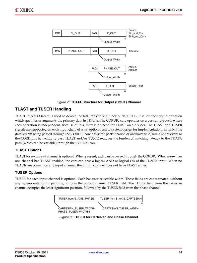
TDATA Structure for Output (DOUT) Channel
The structure of m_axis_dout_tdata is more complex. This port may contain several combinations of outputsubfields X_OUT, Y_OUT and PHASE_OUT, depending on the Functional Selection parameter. The possibleformats are shown with the corresponding functional selections in Figure 7.
X-Ref Target - Figure 4
Figure 4: Blocking Mode
X-Ref Target - Figure 5
Figure 5: TDATA Structure for Cartesian Channel
X-Ref Target - Figure 6
Figure 6: TDATA Structure for Phase Channel
aclk
s_axis_cartesian_tvalid
s_axis_cartesian_tready
s_axis_cartesian_tdata
s_axis_phase_tvalid
s_axis_phase_tready
s_axis_phase_tdata
m_axis_dout_tvalid
m_axis_dout_tready
m_axis_dout_tdata
A1 A2 A3 A4 A5 A6
B1 B2 B3
A1;B1 A2;B2 A3;B3
DS858 October 19, 2011 www.xilinx.com 14Product Specification
LogiCORE IP CORDIC v5.0
TLAST and TUSER Handling
TLAST in AXI4-Stream is used to denote the last transfer of a block of data. TUSER is for ancillary informationwhich qualifies or augments the primary data in TDATA. The CORDIC core operates on a per-sample basis whereeach operation is independent. Because of this, there is no need for TLAST on a divider. The TLAST and TUSERsignals are supported on each input channel as an optional aid to system design for implementations in which thedata stream being passed through the CORDIC core has some packetization or ancillary field, but is not relevant tothe CORDIC. The facility to pass TLAST and/or TUSER removes the burden of matching latency to the TDATApath (which can be variable) through the CORDIC core.
TLAST Options
TLAST for each input channel is optional. When present, each can be passed through the CORDIC. When more thanone channel has TLAST enabled, the core can pass a logical AND or logical OR of the TLASTs input. When noTLASTs are present on any input channel, the output channel does not have TLAST either.
TUSER Options
TUSER for each input channel is optional. Each has user-selectable width. These fields are concatenated, withoutany byte-orientation or padding, to form the output channel TUSER field. The TUSER field from the cartesianchannel occupies the least significant position, followed by the TUSER field from the phase channel.
X-Ref Target - Figure 7
Figure 7: TDATA Structure for Output (DOUT) Channel
X-Ref Target - Figure 8
Figure 8: TUSER for Cartesian and Phase Channel

DS858 October 19, 2011 www.xilinx.com 15Product Specification
LogiCORE IP CORDIC v5.0
Migrating to CORDIC v5.0 from CORDIC v4.0The CORE Generator core update functionality can be used to update an existing XCO file from v4.0 to CORDICv5.0, but the update mechanism alone does not create a core compatible with v4.0. See Instructions for MinimumChange Migration (v4.0 to v5.0).
Table 5 shows the changes to XCO parameters from version 4.0 to version 5.0.
Table 5: XCO Parameter Changes from v4.0 to v5.0
Version 4.0 Version 5.0 Notes
Component_Name Component_Name Unchanged
Functional_Selection Functional_Selection Unchanged
Architectural_Configuration Architectural_Configuration Unchanged
Pipelining_Mode Pipelining_Mode Unchanged
Data_Format Data_Format Unchanged
Phase_Format Phase_Format Unchanged
Input_Width Input_Width Unchanged
Register_Inputs Register_Inputs Unchanged
Output_Width Output_Width Unchanged
Register_Inputs Register_Inputs Unchanged
Round_Mode Round_Mode Unchanged
Iterations Iterations Unchanged
Precision Precision Unchanged
Coarse_Rotation Coarse_Rotation Unchanged
Compensation_Scaling Compensation_Scaling Unchanged
CE ACLKEN Renamed only.
SCLR ARESETN Renamed. Note that the XCO parameter has not changed,but the signal in question is now active low.
ND Deprecated.
RDY Deprecated.
X_OUT Deprecated. If X_OUT is not connected, unused logic isremoved automatically.
Y_OUT Deprecated. If Y_OUT is not connected, unused logic isremoved automatically.
Phase_Output Deprecated. If PHASE_OUT is not connected, unused logicis removed automatically.
cartesian_has_tuser New addition in v5.0
cartesian_tuser_width New addition in v5.0
cartesian_has_tlast New addition in v5.0
phase_has_tuser New addition in v5.0
phase_tuser_width New addition in v5.0
phase_has_tlast New addition in v5.0
flow_control New addition in v5.0
optimize_goal New addition in v5.0
out_tready New addition in v5.0
out_tlast_behv New addition in v5.0

DS858 October 19, 2011 www.xilinx.com 16Product Specification
LogiCORE IP CORDIC v5.0
Latency Changes
With the addition of AXI4-Stream interfaces, the latency of the CORDIC core v5.0 is different compared to v4.0 forAXI Blocking mode. Latency is the same as v4.0 in v5.0 for AXI NonBlocking mode. Importantly, when in BlockingMode, the latency of the core is variable due to the FIFO nature of the AXI4-Stream protocol, so only the minimumpossible latency can be determined. Relative to v4.0, with Blocking and Output TREADY present, minimum latencyis 3 cycles greater. With no output TREADY, minimum latency is increased by one cycle only.
Instructions for Minimum Change Migration (v4.0 to v5.0)
Use the following information to configure the CORDIC core v5.0 to most closely mimic the behavior of v4.0.
Parameters
• Set FlowControl to NonBlocking.
All other new parameters default to false and can be ignored.
Ports
• Rename and map signals as detailed in Port Changes.
• Map ND to both s_axis_cartesian_tvalid and s_axis_phase_tvalid, if present for the function in question.
• Map RFD to s_axis_cartesian_tready or s_axis_phase_tready.
• Map RDY to m_axis_dout_tvalid.
Performance and resource use is mostly unchanged compared with CORDIC v4.0 other than small changes due tothe use of a different version of ISE tools.
Table 6: Port Changes from Version v4.0 to v5.0
Version 4.0 Version 5.0 Notes
CLK aclk Rename only
CE aclken Rename only
SCLR aresetn Rename and change of sense (now active low). Note that aresetn should be asserted for a minimum of 2 cycles.
ND Deprecated. However, this is analogous to the TVALID signals. SeeInstructions for Minimum Change Migration (v4.0 to v5.0).
RFD Deprecated. However, this is analogous to the TREADY signals. SeeInstructions for Minimum Change Migration (v4.0 to v5.0).
RDY Deprecated. However, this is analogous to the m_axis_dout_tvalid. SeeInstructions for Minimum Change Migration (v4.0 to v5.0).
X_IN s_axis_cartesian_tdata subfield subfield of s_axis_cartesian_tdata See TDATA Packing.
Y_IN s_axis_cartesian_tdata subfield subfield of s_axis_cartesian_tdata. See TDATA Packing.
PHASE_IN s_axis_phase_tdata subfield s_axis_phase_tdata(N-1:0)
X_OUT m_axis_dout_tdata subfield Subfield of m_axis_dout_tdata. See TDATA Packing.
Y_OUT m_axis_dout_tdata subfield Subfield of m_axis_dout_tdata. See TDATA Packing.
PHASE_OUT m_axis_dout_tdata subfield Subfield of m_axis_dout_tdata. See TDATA Packing.

DS858 October 19, 2011 www.xilinx.com 17Product Specification
LogiCORE IP CORDIC v5.0
The CORDIC AlgorithmThe CORDIC algorithm was initially designed to perform a vector rotation, where the vector (X,Y) is rotatedthrough the angle yielding a new vector (X’,Y’).
Vector Rotation Equation
1a) Equation 1
1b)
1c)
The CORDIC algorithm performs a vector rotation as a sequence of successively smaller rotations, each of angleatan(2-i), known as micro-rotations. Equation 2 shows the expression for the ith iteration where i is the iteration indexfrom 0 to n.
Expression for the ith microrotation
2a) Equation 2
2b)
2c)
= (+ or -) 1, where is the direction of rotation.
See Vector Rotation or Vector Translation for details on selecting . Each micro-rotation stage can be expressed asa simple shift and add/subtract operation. Equation 3 shows the Vector rotation expression for the nth iteration.Vector rotation expressed as a series of ‘n’ micro-rotations
3a) Equation 3
3b)
3c)
= (+ or -) 1.
The CORDIC algorithm can be used to generate either a vector rotation or a vector translation.
Vector Rotation
Vector rotation rotates the vector (X, Y) through the angle to yield a new vector (X’,Y’), as illustrated in Figure 9.
Vector rotation is performed by selecting , such that converges towards zero; that is, when >= 0, is setto -1 and when < 0, is set +1.
Vector Rotation Equations
4a) Equation 4
4b)
4c)
θ
X' = θ( )cos X× θ( ) Y×sin–( )
Y' = θ( )cos Y× θ( )sin X×+( )
θ' 0=
xi 1+ = xi αi yi 2 i–⋅ ⋅–
yi 1+ = yi αi xi 2 i–⋅ ⋅+
θi 1+ = θi αi 2 i– )( )atan⋅+
αi αi
αi
X' = 2 i–( )atan( ) Xi αiYi2i–
–( )cos
i 1=
n
∏
Y' = 2 i–( )atan( )cos Yi αiXi2i–
+( )i 1=
n
∏
θ' θ αi 2i–( )atan⋅( )–
i 1=
n
=
αi
θ
αi θ' θi 1– αiθi 1– αi
X′ Zn θ( )cos X× θ( )sin Y×–( )×=
Y′ Zn θ( )cos Y× θ( )sin X×+( )×=
θ' = 0

DS858 October 19, 2011 www.xilinx.com 18Product Specification
LogiCORE IP CORDIC v5.0
Vector Translation
Vector translation rotates the vector (X_IN,Y_IN) around the circle until the Y component equals zero as illustratedin Figure 10. The outputs from vector translation are the magnitude, X’, and phase, , of the input vector (X,Y).
Vector translation is performed by selecting such that Y’ converges towards zero; that is, when Yi-1 >= 0, is setto -1 and when Yi-1 < 0, is set +1.
Vector Translation Equations
5a) Equation 5
5b)
5c)
The CORDIC Scale Factor
The outputs of the CORDIC algorithm, equations 4 and 5, are equivalent to a vector rotation or vector translationscaled by a constant Zn. The constant Zn is known as the CORDIC scale factor.
The CORDIC Scale Factor
6a) Equation 6
The Taylor series expansion of acos (atan (2-i)) is (1 + 2-2i)-1/2. Hence, the constant Zn can be expressed as
6b)
The CORDIC scale factor, Zn, is only dependent on the number of iterations, n. Only functional configurationsRotate, Translate, Rectangular to Polar, and Polar to Rectangular are affected by the CORDIC scale factor. Whenthese functional configurations are selected, the CORDIC core provides the option of multiplying by 1 / Zn tocancel out the scaling factor. See Advanced Configuration Parameters for more information.
Zn =
1
2 i–( )atan( )acosi 1=
n
∏-----------------------------------------------------
θ'
αi αiαi
X′ Zn X2
Y2
+( )×=
Y' = 0
θ' = XY---- atan
Zn =
1
2 i–( )atan( )acosi 1=
n
∏-----------------------------------------------------
Zn =
1
2 i–( )atan( )acos
i 1
n
∏-----------------------------------------------------
Zn = 1 2 2 i–+( )1 2/
i 1=
n
∏

DS858 October 19, 2011 www.xilinx.com 19Product Specification
LogiCORE IP CORDIC v5.0
Output Quantization Error
The Output Quantization Error can be split into two components; the Output Quantization Error due to the InputQuantization (OQEIQ), and the Output Quantization Error due to Internal Precision (OQEIP).
OQEIQ is due to the 1/2 lsb of quantization noise on the X_IN,Y_IN and PHASE_IN inputs. In a vector rotation thisinput quantization noise results in OQEIQ of 1/2 an lsb on both the X_OUT and Y_OUT outputs. In a vectortranslation this input quantization noise results in OQEIQ of 1/2 an lsb on the X_OUT output; however, OQEIQ onthe phase output is dependent on the ratio (Y_IN/ X_IN). Thus for small X_IN inputs the effect of inputquantization noise on OQEIQ is greatly magnified.
OQEIP is due to the limited precision of internal calculations. In the CORDIC core the default internal precision isset such that the accumulated OQEIP is less than 1/2 the OQEIQ. The internal precision can be manually set to(input width + output width + log2(output_width)). This reduces OQEIP to 1/2 an lsb (the phase is calculated to fullprecision regardless of the magnitude input vector).
The Output Quantization Error, for a CORDIC core with default internal precision, is dominated by OQEIQ.OQEIQ can only be reduced by increasing the number of significant magnitude bits in the input vector(X_IN,Y_IN). Increasing the internal precision or zero padding X_IN and Y_IN inputs only affects OQEIP and hasminimal effect on the total output quantization error.
The effect of input quantization and internal quantization on the CORDIC phase output quantization error isillustrated in the following examples:
Example 1a: The quantization error in phase output for a small input vector, (Xin_small, Yin_small).
Xin_small : “0000000001” => 1/256.
Yin_small : “0000000001” => 1/256.
Vector translation with no input quantization:
Xin_ideal : “0000000001” => 1/256.
Yin_ideal : “0000000001” => 1/256.
Pout_ideal : “0001100100” => 0.79.
Output quantization error due to the input quantization:
Xin_Quant = Xin_small - 1/2 lsb and Yin_Quant = Yin_small + 1/2 lsb.
Xin_Quant : “00000000001” => 1/512.
Yin_Quant : “00000000011” => 3/512.
Pout_Quant : “0010100000” =>1.25.
OQEIQ = abs( abs(Pout_Quant) - abs(Pout_Ideal) ).
OQEIQ = "0000111100" => 0.47.
Output quantization error due to the internal precision:
Xin_cordic : “0000000001” => 1/256.
Yin_cordic : “0000000001” => 1/256.
Pout_cordic : “0001111010” => 0.95.
OQEIP = abs( abs(Pout_cordic) - abs(Pout_Ideal) ).
OQEIP = "0000010110" => 0.17.

DS858 October 19, 2011 www.xilinx.com 20Product Specification
LogiCORE IP CORDIC v5.0
Example 1b: Quantization error in phase output for a large input vector, (Xin_large, Yin_large).
Xin_large : “0100000000” => 256/256.
Yin_large : “0100000000” => 256/256.
Vector translation with no input quantization:
Xin_ideal : “0100000000” => 256/256.
Yin_ideal : “0100000000” => 256/256.
Pout_ideal : “0001100100” => 0.79.
Output quantization error due to the input quantization:
Xin_Quant = Xin_large - 1/2 lsb and Yin_Quant = Yin_small + 1/2 lsb.
Xin_Quant : “00111111111” => 511/512.
Yin_Quant : “01000000001” => 513/512.
Pout_Quant : “0001100101” =>0.79.
OQEIQ = abs( abs(Pout_Quant) - abs(Pout_Ideal)).
OQEIQ = "0000000001" => 0.00.
Output quantization error due to the internal precision:
Xin_cordic : “0100000000” => 256/256.
Yin_cordic : “0100000000” => 256/256.
Pout_cordic : “0001100100” => 0.79.
OQEIP = abs( abs(Pout_cordic) - abs(Pout_Ideal)).
OQEIP = "0000000000" => 0.00
Functional Description
Vector Rotation
Polar to Rectangular Translation
When the vector rotation functional configuration is selected, the input vector (X_IN, Y_IN) is rotated by the inputangle, , using the CORDIC algorithm. This generates the scaled output vector, Zi * (X’, Y’), shown in Figure 9.
The input subfields, X_IN, Y_IN and PHASE_IN, are limited to the ranges given in Table 7 when coarse rotation isset. Inputs outside these ranges produce unpredictable results. See Input/Output Data Representation for moreinformation about the CORDIC binary data formats.
An optional coarse rotation module is provided to extend the range of the input subfields, X_IN, Y_IN andPHASE_IN, to the full circle. For this functional configuration, the coarse rotation module is selected by default, butcan be manually deselected. See Advanced Configuration Parameters for more information. When this option is notset, inputs must be constrained to lie in the first quadrant, -Pi/4 to + Pi/4.
An optional compensation scaling module is provided to compensate for the CORDIC scale factor Zi. For thisfunctional configuration, the compensation scaling module is selected by default, but can be manually deselected.See Advanced Configuration Parameters for more information.
A Polar to Rectangular Translation can be implemented by setting the functional configuration to vector rotation,the input vector to (Mag, 0), and the rotation angle to , shown in Figure 10.
θ
θ

DS858 October 19, 2011 www.xilinx.com 21Product Specification
LogiCORE IP CORDIC v5.0
Vector rotation is linear with respect to magnitude; thus the user can scale the input/output range; that is:
if (X, Y) rotated by angle = (X’, Y’) thenK*(X, Y) rotated by angle = K*(X’, Y’).
Example 1: Vector Rotation
The input vector, (Xin, Yin), and the output vector, (Xout, Yout) are expressed as a pair of fixed-point 2’scomplement numbers with an integer width of 2 bits (1QN format). The input rotation angle, Pin radians, is alsoexpressed as a fixed-point 2’s complement number but with an integer width of 3 bits (2QN format). See theInput/Output Data Representation section for further information on the CORDIC binary data formats.
In this example, the input/output width is set to 10 bits and the output vector (Xout, Yout) is scaled to compensatefor the CORDIC scale factor.
Xin : “0010110101” => 00.10110101 => 0.707
Yin : “0001000000” => 00.01000000 => 0.25
Pin : “1100110111” => 110.0110111 => -Pi/2
Xout : “0001000001” => 00.01000001 => 0.25
Yout : “1101001011” => 11.01001011 => -0.707
Vector Translation
Rectangular to Polar Translation
When the vector translational functional configuration is selected, the input vector (X_IN,Y_IN) is rotated using theCORDIC algorithm until the Y component is zero. This generates the scaled output magnitude, Zi *Mag(X_IN,Y_IN), and the output phase, Atan(Y_IN/X_IN), shown in Figure 10.
The inputs, X_IN and Y_IN, are limited to the ranges given in Table 8 when coarse rotation is set. Inputs outsidethese ranges produce unpredictable results. See Input/Output Data Representation for more information aboutCORDIC binary data formats.
X-Ref Target - Figure 9
Figure 9: Vector Rotation
Table 7: Vector Rotation I/O
Signal Range Description
X_IN -1 <= X_IN<=1 Input X Coordinate
Y_IN -1 <= Y_IN<=1 Input Y Coordinate
PHASE_IN -Pi <= PHASE_IN <= Pi Input Rotation Angle
X_OUT -Sqrt(2) <= X_OUT<= Sqrt(2) Output X Coordinate * Z
Y_OUT -Sqrt(2) <= Y_OUT<= Sqrt(2) Output Y Coordinate * Z
θθ
�

DS858 October 19, 2011 www.xilinx.com 22Product Specification
LogiCORE IP CORDIC v5.0
An optional coarse rotation module is provided to extend the range of inputs, X_IN and Y_IN, to the full circle. Forthis functional configuration, the coarse rotation module is selected by default, but can be manually deselected. SeeAdvanced Configuration Parameters for more information. When this option is not set, inputs must be constrainedto lie in the first quadrant, -Pi/4 to + Pi/4.
An optional compensation scaling module is provided to compensate for the CORDIC scale factor Zi. For thisfunctional configuration, the compensation scaling module is selected by default, but can be manually deselected.See Advanced Configuration Parameters for more information.
A rectangular to polar translation can be implemented by setting functional configuration to vector translation, andthe input vector to (X,Y), shown in Figure 10.
Vector translation is linear with respect to magnitude, making the input/output range scalable:
if vector (X_IN, Y_IN) is translated to (X’, ’), thenvector K*(X_IN, Y_IN) is translated to K*(X’, ’).
The phase angle of a zero length vector, (0,0), is indeterminate and the output phase angle generated by the core isunpredictable.
The accuracy of the phase output from the CORDIC vector translation algorithm is limited by the number ofsignificant magnitude bits of the input vector (X_IN, Y_IN). See CORE Generator GUI and Parameters for moreinformation.
Example 2: Vector Translation
The individual input vector elements, (X_IN, Y_IN), and the output magnitude, X_OUT, are expressed asfixed-point 2’s complement numbers with an integer width of 2 bits (1QN format). The output phase angle,PHASE_OUT radians, is expressed as a fixed-point 2’s complement number with an integer width of 3 bits (2QNformat).
In this example the input/output width is set to 10 bits and the output X_OUT is scaled to compensate for theCORDIC scale factor.
X_IN : “0010110101” => 00.10110101 => 0.707
X-Ref Target - Figure 10
Figure 10: Vector Translation (Polar to Rectangular)
Table 8: Vector Translation I/O
Signal Range Description
X_IN -1 <= X_IN <= 1 Input X Coordinate
Y_IN -1 <= Y_IN <= 1 Input Y Coordinate
X_OUT 0 <= X_OUT <= Sqrt(2) Output Magnitude * Z
PHASE_OUT -Pi <= Phase Out <= Pi Output Phase
θθ
�

DS858 October 19, 2011 www.xilinx.com 23Product Specification
LogiCORE IP CORDIC v5.0
Y_IN : “0001000000” => 00.01000000 => 0.25
X_OUT : “0011000000” => 00.11000000 => 0.75
PHASE_OUT : “0000101011” => 000.0101011 => 0.336
Sin and Cos
When the Sin and Cos functional configuration is selected, the unit vector is rotated by input angle, , using theCORDIC algorithm. This generates the output vector (Cos( ), Sin( )).
The input PHASE_IN is limited to the range given in Table 9 when coarse rotation is set. Inputs outside this rangeproduce unpredictable results. See Input/Output Data Representation for more information about CORDIC binarydata formats.
An optional coarse rotation module is provided to extend the range of input angle, , to the full circle. For thisfunctional configuration, the coarse rotation module is selected by default, but can be manually deselected. SeeAdvanced Configuration Parameters for more information. When this option is not set, inputs must be constrainedto lie in the first quadrant, -Pi/4 to + Pi/4.
The compensation scaling module is disabled for the Sin and Cos functional configuration as it is internallypre-scaled to compensate for the CORDIC scale factor.
Example 3: Sin and Cos
The input angle, PHASE_IN, is expressed as a fixed-point 2’s complement number with an integer width of 3 bits(2QN format). The output vector, (X_OUT, Y_OUT), is expressed as a pair of fixed-point 2’s complement numberswith an integer width of 2 bits (1QN format).
In this example the input/output width is set to 10 bits.
PHASE_IN : “0001100100” => 000.1100100 => 0.781
X_OUT : “0010110110” => 00.10110110 => 0.711
Y_OUT : “0010110100” => 00.10110100 => 0.703
Table 9: Sin and Cos
Signal Range Description
PHASE_IN -Pi <= PHASE_IN <= Pi Input Angle
X_OUT -1 <= X_OUT <= 1 Output Cos( )
Y_OUT -1 <= Y_OUT <= 1 Output Sin( )
θθ θ
θ
θ
θ
θ
DS858 October 19, 2011 www.xilinx.com 24Product Specification
LogiCORE IP CORDIC v5.0
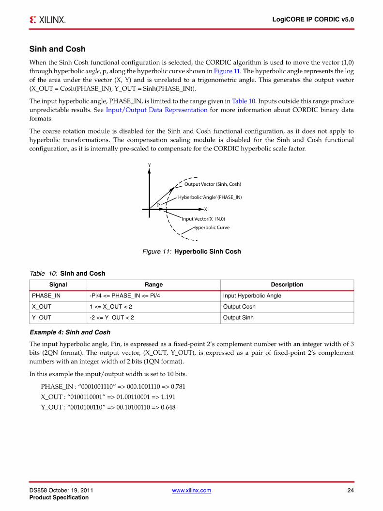
Sinh and Cosh
When the Sinh Cosh functional configuration is selected, the CORDIC algorithm is used to move the vector (1,0)through hyperbolic angle, p, along the hyperbolic curve shown in Figure 11. The hyperbolic angle represents the logof the area under the vector (X, Y) and is unrelated to a trigonometric angle. This generates the output vector(X_OUT = Cosh(PHASE_IN), Y_OUT = Sinh(PHASE_IN)).
The input hyperbolic angle, PHASE_IN, is limited to the range given in Table 10. Inputs outside this range produceunpredictable results. See Input/Output Data Representation for more information about CORDIC binary dataformats.
The coarse rotation module is disabled for the Sinh and Cosh functional configuration, as it does not apply tohyperbolic transformations. The compensation scaling module is disabled for the Sinh and Cosh functionalconfiguration, as it is internally pre-scaled to compensate for the CORDIC hyperbolic scale factor.
Example 4: Sinh and Cosh
The input hyperbolic angle, Pin, is expressed as a fixed-point 2’s complement number with an integer width of 3bits (2QN format). The output vector, (X_OUT, Y_OUT), is expressed as a pair of fixed-point 2’s complementnumbers with an integer width of 2 bits (1QN format).
In this example the input/output width is set to 10 bits.
PHASE_IN : “0001001110” => 000.1001110 => 0.781
X_OUT : “0100110001” => 01.00110001 => 1.191
Y_OUT : “0010100110” => 00.10100110 => 0.648
X-Ref Target - Figure 11
Figure 11: Hyperbolic Sinh Cosh
Table 10: Sinh and Cosh
Signal Range Description
PHASE_IN -Pi/4 <= PHASE_IN <= Pi/4 Input Hyperbolic Angle
X_OUT 1 <= X_OUT < 2 Output Cosh
Y_OUT -2 <= Y_OUT < 2 Output Sinh
�

DS858 October 19, 2011 www.xilinx.com 25Product Specification
LogiCORE IP CORDIC v5.0
ArcTan
When the ArcTan functional configuration is selected, the input vector (X_IN,Y_IN) is rotated (using the CORDICalgorithm) until the Y component is zero. This generates the output angle, Atan(Y_IN/X_IN).
The inputs, X_IN and Y_IN, are limited to the ranges given in Table 11 when coarse rotation is set. Inputs outsidethese ranges produce unpredictable outputs. See Input/Output Data Representation for more information aboutCORDIC binary data formats.
An optional coarse rotation module is provided to extend the range of inputs X_IN and Y_IN to the full circle. Forthis functional configuration, the coarse rotation module is selected by default, but can be manually deselected. SeeAdvanced Configuration Parameters for more information. When this option is not set, inputs must be constrainedto lie in the first quadrant, -Pi/4 to + Pi/4.
The compensation scaling module is disabled for the ArcTan functional configuration as no magnitude data isoutput. The ArcTan of a zero length vector, (0,0), is indeterminate and the output angle generated by the core isundefined.
The accuracy of the output angle from the CORDIC vector translation algorithm is limited by the number ofsignificant magnitude bits of the input vector (X_IN, Y_IN). See Output Quantization Error for more information.
Example 5: ArcTan
The input vector (X_IN, Y_IN) is expressed as a pair of fixed-point 2’s complement numbers with an integer widthof 2 bits (1QN format). The output angle, Pout radians, is expressed as a fixed-point 2’s complement number withan integer width of 3 bits (2QN format).
In this example, the input/output width is set to 10 bits.
X_IN : “0010100000” => 00.10100000 => 0.625
Y_IN : “0010000000” => 00.10000000 => 0.500
PHASE_OUT : “0001010110” => 000.1010110=> 0.672
Table 11: ArcTan
Signal Range Description
X_IN -1 <= X_IN <=1 Input X Coordinate
Y_IN -1 <= Y_IN <=1 Input Y Coordinate
PHASE_OUT -Pi <= PHASE_OUT <= Pi Output Angle

DS858 October 19, 2011 www.xilinx.com 26Product Specification
LogiCORE IP CORDIC v5.0
ArcTanh
When the ArcTanh functional configuration is selected, the CORDIC algorithm is used to move the input vector(X_IN,Y+IN) along the hyperbolic curve (Figure 12) until the Y component reaches zero. This generates thehyperbolic “angle,” Atanh(Y_IN/X_IN). The hyperbolic angle represents the log of the area under the vector(X_IN,Y_IN) and is unrelated to a trigonometric angle.
The inputs, X_IN and Y_IN, are limited to the ranges given in Table 12. Inputs outside these ranges produceunpredictable outputs. Additionally, Y_IN must be less than or equal to (4/5 * X_IN) or the CORDIC algorithm doesnot converge. See Input/Output Data Representation for more information about CORDIC binary data formats.
The coarse rotation module is disabled for the ArcTanh functional configuration, as it does not apply to hyperbolictransformations.
The compensation scaling module is disabled for the ArcTanh functional configuration as no output magnitudedata is output.
Example 6: ArcTanh
The input vector, (X_IN, Y_IN), is expressed as a pair of fixed-point 2’s complement numbers with an integer widthof 2 bits (1QN format). The output, Pout, is expressed as a fixed-point 2’s complement number with an integerwidth of 3 bits (2QN format).
In this example, the input/output width is set to 10 bits.
X_IN : “0001100101” => 00.01100101 => 0.395
Y_IN : “0001100101” => 00.01100101 => 0.395
PHASE_OUT : “0001110001” => 000.1110001=> 0.883
X-Ref Target - Figure 12
Figure 12: Hyperbolic ArcTan
Table 12: ArcTanh
Signal Range Description
X_IN 0 < X_IN <2 Input X Coordinate
Y_IN -2 <= Y_IN < 2-X_IN * 4/5 <= Y_IN <= X_IN * 4/5
Input Y Coordinate
PHASE_OUT -Pi/2 <= PHASE_OUT<= Pi/2 Output Hyperbolic Angle
�

DS858 October 19, 2011 www.xilinx.com 27Product Specification
LogiCORE IP CORDIC v5.0
Square Root
When the square root functional configuration is selected, a simplified CORDIC algorithm is used to calculate thepositive square root of the input. The input, X_IN, and the output, X_OUT, are always positive and are bothexpressed as either unsigned fractions or unsigned integers. When the data format is set to Unsigned Fraction, X_INis limited to the range: 0 <= X_IN < +2. When data format is set to Unsigned Integer, X_IN is limited to the range: 0<= X_IN < 2**Input Width, and the output width is determined automatically based on the input width. SeeInput/Output Data Representation for more information about CORDIC binary data formats.
The coarse rotation module is disabled because coarse rotation is not required for the Square Root functionalconfiguration. The compensation scaling module is disabled because no output compensation is required for theSquare Root functional configuration.
Example 7a: Square Root - Unsigned Fraction
The input, X_IN, and output, X_OUT, are expressed as an unsigned fixed-point number with an integer width of 1bit.
In this example the input/output width is set to 10 bits.
X_IN : “0000100000” => 0.000100000 => 1/16
X_OUT : “0010000000” => 0.010000000 => 1/4
Example 7b: Square Root - Unsigned Integer
The input, X_IN, is expressed as an unsigned integer. The output, X_OUT, is expressed as an unsigned integer. Inthis example the input width is set to 10 bits so the output width is automatically set to 6 bits.
X_IN : “0000100000” => 32
X_OUT : “000110” => 6
Table 13: Square Root
Signal Range Description
X_IN Unsigned Fraction: 0 <= X_IN < +2Unsigned Integer: 0 <= X_IN < 2**Input Width
Input X Value
X_OUT Unsigned Fraction: 0 <= X_OUT < +2Unsigned Integer: 0 <= X_OUT < 2**[int(Input Width/2)+1]
Output Square Root

DS858 October 19, 2011 www.xilinx.com 28Product Specification
LogiCORE IP CORDIC v5.0
Architectural ConfigurationTwo architectural configurations are available for the CORDIC core:
• Parallel, with single-cycle data throughput and large silicon area
• Word Serial, with multiple-cycle throughput and a smaller silicon area.
This choice is independent of choices relating to AXI4-Stream behavior.
Parallel Architectural Configuration
The CORDIC algorithm requires approximately one shift-addsub operation for each bit of accuracy. A CORDICcore with a parallel architectural configuration implements these shift-addsub operations in parallel using an arrayof shift-addsub stages.
A parallel CORDIC core with N bit output width has a latency of N cycles and produces a new output every cycle.The implementation size of this parallel circuit is directly proportional to the internal precision times the number ofiterations.
Word Serial Architectural Configuration
The CORDIC algorithm requires approximately one shift-addsub operation for each bit of accuracy. A CORDICcore implemented with the word serial architectural configuration, implements these shift-addsub operationsserially, using a single shift-addsub stage and feeding back the output.
A word serial CORDIC core with N bit output width has a latency of N cycles and produces a new output every Ncycles. The implementation size this iterative circuit is directly proportional to the internal precision.
Input/Output Data Representation
Cartesian Operands and Results
The S_AXIS_CARTESIAN_TDATA subfields are: X_IN, Y_IN. The M_AXIS_DOUT_TDATA subfields are X_OUTand Y_OUT.
For Functional Configurations, Rotate, Translate, Sin, Cos and Atan, the cartesian operands and results arerepresented using fixed-point 2’s complement numbers with an integer width of 2 bits. The integer width is fixedregardless of the word width; the remainder of the bits are used for the fractional portion of the number. Using theQ Numbers Format this representation is described as 1QN where N = word width - 2. It can also be described asFix(N+2)_N using the System Generator Fix format.
Input operands, X_IN and Y_IN, must be in the range: -1 <= input data signal <= 1. Input data outside this rangeproduces undefined results.
Using a 10-bit word width, +1 and -1 are represented as:
"0100000000" => 01.00000000 => +1.0
"1100000000" => 11.00000000 => - 1.0
For the Square Root Functional Configuration, the Data Signals, X_IN and X_OUT, are both represented in eitherUnsigned Fractional or Unsigned Integer data format.
The input operand, X_IN, must be in the range: 0 <= X_IN < +2 when data format is set to Unsigned Fraction or inthe range 0 <= X_IN < 2**Input Width when data format is set to Unsigned Integer.

DS858 October 19, 2011 www.xilinx.com 29Product Specification
LogiCORE IP CORDIC v5.0
When Unsigned Fractional data format has been selected the Data Signals are represented using a unsignedfixed-point number with an integer with of 1 bit. The integer width is fixed and the remainder of the word is usedto represent the fractional portion of the number. Using the System Generator Fix format this representation isdescribed as UFix(N+1)_N, where is the number of fractional bits being used and is defined as N = word width -1.The Q Number format is used to represent signed 2’s complement numbers and is therefore not suitable to describethe representation format used by the square root function.
Phase Signals
The S_AXIS_PHASE_TDATA Phase operand is PHASE_IN. The M_AXIS_DOUT_TDATA phase output is calledPHASE_OUT. The phase signals are always represented using a fixed-point 2’s complement number with aninteger width of 3 bits. As with the data signals the integer width is fixed and any remaining bits are used for thefractional portion of the number. The Phase Signals require an increased integer width to accommodate theincreased range of values they must represent when the Phase Format is set to Radians.
When Phase Format is set to Radians, PHASE_IN must be in the range: -Pi <= (PHASE_IN) <= Pi. PHASE_INoutside this range produce undefined results.
In 2Q7, or Fix10_7, format values, +Pi and -Pi are:
"01100100100" => 011.00100100 => +3.14
"10011011100" => 100.11011100 => - 3.14
When Phase Format is set to Scaled Radians PHASE_IN must be in the range: -1 <= (PHASE_IN) <= +1. PHASE_INoutside this range produce undefined results.
In 2Q7, or Fix10_7 format values, +1 and -1 are represented as:
"0010000000" => 001.0000000 => +1.0
"1110000000" => 111.0000000 => - 1.0
Q Numbers Format
An XQN format number is an 1+X+N bit 2’s complement binary number; a sign bit followed by X integer bitsfollowed by an N bit mantissa (fraction). XQN format can be used to express numbers in the range ( -2X ) to ( 2X - 2(-N) ). An equivalent notation using the System Generator Fix format, defined asFixword_length_fractional_length, would be Fix(1+X+N)_N.
A number using Q15 format is equivalent to a number using Fix16_15 representation, and a number in 1Q15 formatis equivalent to a number using Fix17_15 representation.
Table 14 and Table 15 contain examples of XQN Format Numbers.
Table 14: 1QN Format Data: Example of a 1Q7 (or Fix9_7) Format Number
(Sign)Bit 8 Bit 7 Bit 6 Bit 5 Bit 4 Bit 3 Bit 2 Bit 1 Bit 0
+1 0 1 0 0 0 0 0 0 0
-1 1 1 0 0 0 0 0 0 0
+Pi/4 0 0 1 1 0 0 1 0 0
-Pi/4 1 1 0 0 1 1 0 1 1
Fractional Bits

DS858 October 19, 2011 www.xilinx.com 30Product Specification
LogiCORE IP CORDIC v5.0
Mapping Different Data Formats
Rotate, Translate, Sin, Cos and Atan Functional Configurations
For Functional Configurations Rotate, Translate, Sin, Cos and Atan it is possible to map alternative Data Signalformats to the fixed integer width fractional number used by the CORDIC core.
When the input and output width differ, care must be taken to re-interpret the CORDIC output.
Example 8a develops Example 2: Vector Translation to demonstrate a possible remapping.
Example 8a
The Vector Translation function determines the magnitude and phase angle of a given input vector (X_IN, Y_IN).The input and output width is set to 10 bits. The standard CORDIC data representation is Fix10_8, the alternativeformat being mapped onto the input of the CORDIC is Fix10_1.
X_IN value: "0010110101"
Y_IN value: "0001000000"
Table 15: 2QN Format Phase: Example of a 2Q6 (or Fix9_6) Format Number
(Sign)Bit 8 Bit 7 Bit 6 Bit 5 Bit 4 Bit 3 Bit 2 Bit 1 BIt 0
+1 0 0 1 0 0 0 0 0 0
-1 1 1 1 0 0 0 0 0 0
+Pi 0 1 1 0 0 1 0 0 1
-Pi 1 0 0 1 1 0 1 1 1
Fractional Bits
Table 16: Example 8: Mapping an Alternative Data Format onto the X_IN input
SignBit 9 Bit 8 Bit 7 Bit 6 Bit 5 Bit 4 Bit 3 Bit 2 Bit 1 Bit 0 Decimal
Value
Binary Value 0 0 1 0 1 1 0 1 0 1
Fix10_8 weighting -21 20 2-1 2-2 2-3 2-4 2-5 2-6 2-7 2-8 0.707
Fix10_1 weighting -28 27 26 25 24 23 22 21 20 2-1 90.5
Table 17: Example 8: Mapping an Alternative Data Format onto the Y_IN input
SignBit 9 Bit 8 Bit 7 Bit 6 Bit 5 Bit 4 Bit 3 Bit 2 Bit 1 Bit 0 Decimal
Value
Binary Value 0 0 1 0 0 0 0 0 0 0
Fix10_8 weighting -21 20 2-1 2-2 2-3 2-4 2-5 2-6 2-7 2-8 0.25
Fix10_1 weighting -28 27 26 25 24 23 22 21 20 2-1 32

DS858 October 19, 2011 www.xilinx.com 31Product Specification
LogiCORE IP CORDIC v5.0
MATLAB® software is used to generate the expected results. Firstly the magnitude and phase angle for thestandard CORDIC input format 1Q8, or Fix10_8 is generated:
>> a=0.707+0.25j
>> magnitude = abs(a)
magnitude = 0.7499
>> phase_angle = angle(a)
phase_angle = 0.3399
Secondly using the mapped input format, 9Q1 or Fix10_1:
>> b=90.5+32j
>> magnitude = abs(b)
magnitude = 95.9909
>> phase_angle = angle(b)
phase_angle = 0.3399
The CORDIC output is:
X_OUT value: "0011000000"
PHASE_OUT value: "0000101011"
Table 18 and Table 19 demonstrate the output value of the CORDIC being interpreted using the two datarepresentation formats.
Table 18: Example 8: X_OUT Interpretation
SignBit 9 Bit 8 Bit 7 Bit 6 Bit 5 Bit 4 Bit 3 Bit 2 Bit 1 Bit 0 Decimal
Value
Binary Value 0 0 1 1 0 0 0 0 0 0
Fix10_8 weighting -21 20 2-1 2-2 2-3 2-4 2-5 2-6 2-7 2-8 0.75
Fix10_1 weighting -28 27 26 25 24 23 22 21 20 2-1 96
Table 19: Example 8: PHASE_OUT Interpretation
SignBit 9 Bit 8 Bit 7 Bit 6 Bit 5 Bit 4 Bit 3 Bit 2 Bit 1 Bit 0 Decimal
Value
Binary Value 0 0 0 0 1 0 1 0 1 1
Fix10_7 weighting -22 21 20 2-1 2-2 2-3 2-4 2-5 2-6 2-7 0.336

DS858 October 19, 2011 www.xilinx.com 32Product Specification
LogiCORE IP CORDIC v5.0
Example 8b
If the output width is less than the input width, the CORDIC reduces the fractional width of the result. When thedata output, X_OUT, is being re-interpreted to an alternative data format, the value must be scaled appropriately.
Table 20 demonstrates how the resulting decimal value might change when the output width is reduced to 8 bits.
A similar situation arises when the output width is greater than the input width. In this case, the CORDIC increasesthe fractional width of the result. When the data output is being re-interpreted to a data format with no fractionalbits, this results in an increased magnitude. This output then needs to be scaled appropriately.
Square Root Functional Configuration
For the Square Root Functional Configuration it is also possible to map other data formats onto the data format ofthe CORDIC but it might be necessary to re-interpret and scale the output.
Example 9 modifies Example 7a: Square Root - Unsigned Fraction.
Example 9
X_IN value: "00001000"
The expected output values for each input format are as follows:
UFix8_7 format: sqrt(0.0625) = 0.25
UFix8_1 format: sqrt(4) = 2
UFix8_0 format: sqrt(8) = 2.8284
The CORDIC output is:
X_OUT value: "00100000"
Table 20: Example 8b: X_OUT Interpretation with Reduced Output Width
SignBit 7 Bit 6 Bit 5 Bit 4 Bit 3 Bit 2 Bit 1 Bit 0 Decimal
Value
Binary Value 0 0 1 1 0 0 0 0
Fix8_6 weighting -21 20 2-1 2-2 2-3 2-4 2-5 2-6 0.75
Fix8_0 weighting -27 26 25 24 23 22 21 20 48
Table 21: Example 9: Mapping an Alternative Data Format onto the X_IN input
Bit 7 Bit 6 Bit 5 Bit 4 Bit 3 Bit 2 Bit 1 Bit 0 DecimalValue
Binary Value 0 0 0 0 1 0 0 0
UFix8_7 weighting 20 2-1 2-2 2-3 2-4 2-5 2-6 2-7 0.0625
UFix8_1 weighting 26 25 24 23 22 21 20 2-1 4
UFix8_0 weighting 27 26 25 24 23 22 21 20 8

DS858 October 19, 2011 www.xilinx.com 33Product Specification
LogiCORE IP CORDIC v5.0
Table 22 demonstrates the output value directly interpreted in each of the input formats.
Table 22 shows that if the output value is directly interpreted in the alternative data format the wrong decimal valueis determined. The output value must be scaled correctly.
The output scaling is determined as follows.
The CORDIC core calculates the square root of input values in the range 0 <= X_IN < 2.
Equation 7
The alternative data format represents values in the range 0<= X_IN < 2N+1 and we wish to calculate:
Equation 8
Interpreting Xalt using the standard CORDIC data format scales the input by 2-N, shown in Table 21.
Equation 9
As Table 22 shows, directly re-interpreting the CORDIC output in the alternative data formats results in an incorrectdecimal value. This is due to the scale factor introduced by the remapping of the input and the square root function.This scaling factor introduced is shown in Equation 9, 2-N/2.
The corrected results are shown:
UFix8_1 weighting: 16/2(6/2) = 2
UFix8_0 weighting: 32/2(7/2) = 2.8284
When N is even the scaling factor is an integer power of two. This can be applied by right shifting the CORDICoutput, X_OUT, by N/2. The example using the UFix8_1 format demonstrates this with a scaling factor of 2-3 = 1/8.
When N is odd the scaling factor is not an integer power of two. This introduces an additional output scaling factorof . The example using UFix8_0 demonstrates this with a scaling factor of 2-7/2 = 2-3.5.
This could be implemented by first scaling the output by a right shift of 4 and then multiplying by . A moreefficient way would be to translate the scaling to the input of the square root function.
Table 22: X_OUT Direct Interpretation
Bit 7 Bit 6 Bit 5 Bit 4 Bit 3 Bit 2 Bit 1 Bit 0 DecimalValue
Binary Value
0 0 1 0 0 0 0 0
UFix8_7 weighting
20 2-1 2-2 2-3 2-4 2-5 2-6 2-7 0.25
UFix8_1 weighting
26 25 24 23 22 21 20 2-1 16
UFix8_0 weighting
27 26 25 24 23 22 21 20 32
Y X=
Yalt Xalt=
Y 2N–
Xalt⋅=
Y 2N–( ) 2⁄
Xalt⋅=
2
22

DS858 October 19, 2011 www.xilinx.com 34Product Specification
LogiCORE IP CORDIC v5.0
This is demonstrated in Equation 10 where 2-N/2=2-M-(1/2).
Equation 10
The scaling becomes a simple divide by 2, or right shift, of the input, X_IN, before applying it to the square rootfunction. Followed by scaling the output, X_OUT, by 2-M.
An input value of 8 is used for the UFix8_0 formatting example. Divided by 2 this gives 4. Table 21 shows that 4maps to 1/32 in the CORDIC input range.
Table 22 shows that the CORDIC output value, 0.0010110, maps to a decimal value of 22 in UFix8_0 formatting.Applying the output scaling of 2-3, or 1/8, gives 2.75. The loss in accuracy is due to representing using only8 bits. If the full accuracy result is used and then re-interpreted to the alternative data format (Fix8_0) and thenscaled, the correct result is obtained; for example:
Performance and Resource UtilizationTables 24 to 35 show performance and resource usage information for a number of different core configurations.The maximum clock frequency results were obtained by double-registering input and output ports to reducedependence on I/O placement. The inner level of registers used a separate clock signal to measure the path from theinput registers to the first output register through the core.
The resource usage results do not include the "characterization" registers above and represent the true logic used bythe core. LUT counts include SRL16s or SRL32s (according to device family).
The map and par options used were:
• map -ol high
• par -ol high
Table 23 shows the parts and speedfiles that were used to generate the results in Tables 24 to 35.
Table 23: Characterization Data Parameters
Family Device Speedfile
Spartan-6 XC6SLX75T-4FGG676 PRODUCTION 1.19 2011-08-01
Virtex-6 XC6VCX75T-1FF784 PRODUCTION 1.10 2011-08-01
Virtex-7 XC7VX330T-1FFG1157 ADVANCED 1.01a 2011-08-01
Kintex-7 XC7K325T-1FBG900 ADVANCED 1.01 2011-08-01
Y 2M–
21–
Xalt⋅⋅=
Y 2M– 1 2⁄–( )
Xalt⋅=
1 32⁄ 0.17678 0.0010110= =
1 32⁄
1 32⁄ 27× 2
3–× 2.8284=

DS858 October 19, 2011 www.xilinx.com 35Product Specification
LogiCORE IP CORDIC v5.0
Tables 24 to 26 contains characterization data for Spartan-6. The results have been generated with automaticallydetermined Iterations and Precision, Coarse Rotation, no Compensation Scaling and Maximum Pipelining.
Table 24: Performance characteristics on Spartan-6 (Case 1 to 11)
Parameter/Result Case 1 Case 2 Case 3 Case 4 Case 5 Case 6 Case 7 Case 8 Case 9 Case
10Case
11
Function Rotate Trans SinCos Atanh Square Root Rotate Trans SinCos Atanh Rotate Trans
Architecture Word Serial
Word Serial
Word Serial
Word Serial
Word Serial Parallel Parallel Parallel Parallel Word
SerialWord Serial
Input/Output Width 16 16 16 16 16 16 16 16 16 32 32
Round Mode Trunc Trunc Trunc Trunc Trunc Trans Trans Trans Trans Nearest Even
Nearest Even
LUT6-FF pairs 586 503 18 342 415 1196 1059 1050 1166 1245 928
LUTs 511 463 17 300 389 1116 986 1010 1128 1079 803
FFs 427 335 17 234 318 1104 992 976 1083 851 631
Block Rams 0 0 0 0 0 0 0 0 0 0 0
XtremeDSP slices 0 0 0 0 0 0 0 0 0 0 0
Max Clock Frequency 205 195 225 169 334 334 298 334 298 164 164
Table 25: Performance characteristics on Spartan-6 (Case 12 to 22)
Parameter/Result
Case 12
Case 13
Case 14
Case 15
Case 16
Case 17
Case 18
Case 19
Case 20
Case 21
Case 22
Function SinCos Atanh Square Root Rotate Trans SinCos Atahn Rotate Trans SinCos Atanh
Architecture Word Serial
Word Serial
Word Serial Parallel Parallel Parallel Parallel Word
SerialWord Serial
Word Serial
Word Serial
Input/Output Width 32 32 32 32 32 32 32 48 48 48 48
Round Mode Nearest Even
Nearest Even
Nearest Even
Nearest Even
Nearest Even
Nearest Even
Nearest Even Trunc Trunc Trunc Trunc
LUT6-FF pairs 928 685 1597 4050 3821 3706 3946 1825 1352 1412 1015
LUTs 856 605 1547 3893 3646 3664 3882 1596 1154 1296 892
FFs 597 419 1293 3869 3672 3588 3786 1210 861 857 616
Block Rams 0 0 0 0 0 0 0 0 0 0 0
XtremeDSP slices 0 0 0 0 0 0 0 0 0 0 0
Max Clock Frequency 175 148 267 257 210 251 246 143 133 133 127
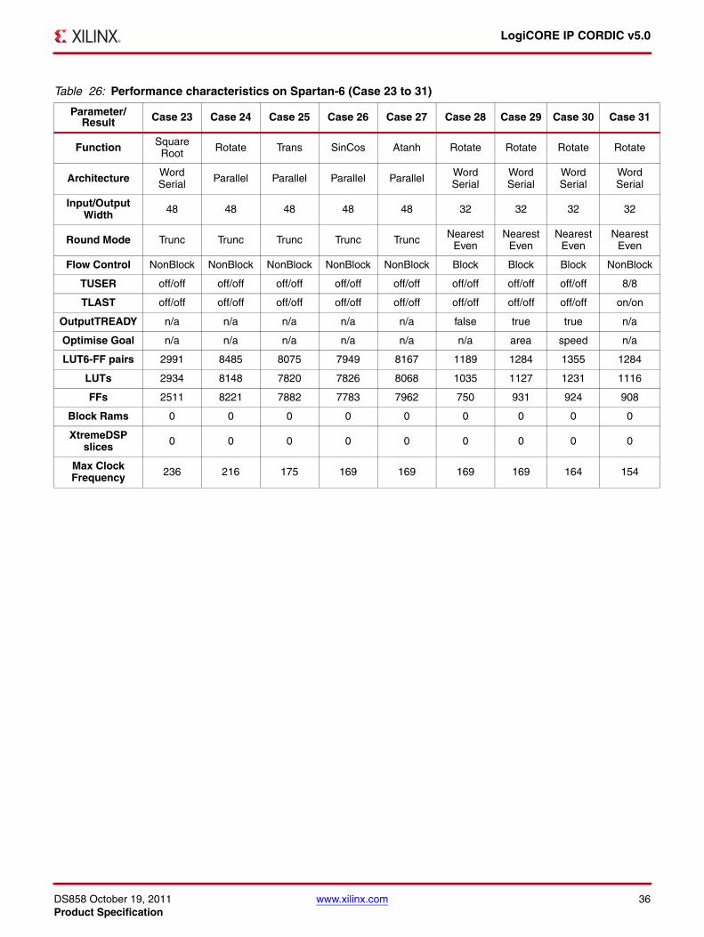
DS858 October 19, 2011 www.xilinx.com 36Product Specification
LogiCORE IP CORDIC v5.0
Table 26: Performance characteristics on Spartan-6 (Case 23 to 31)
Parameter/Result Case 23 Case 24 Case 25 Case 26 Case 27 Case 28 Case 29 Case 30 Case 31
Function Square Root Rotate Trans SinCos Atanh Rotate Rotate Rotate Rotate
Architecture Word Serial Parallel Parallel Parallel Parallel Word
SerialWord Serial
Word Serial
Word Serial
Input/Output Width 48 48 48 48 48 32 32 32 32
Round Mode Trunc Trunc Trunc Trunc Trunc Nearest Even
Nearest Even
Nearest Even
Nearest Even
Flow Control NonBlock NonBlock NonBlock NonBlock NonBlock Block Block Block NonBlock
TUSER off/off off/off off/off off/off off/off off/off off/off off/off 8/8
TLAST off/off off/off off/off off/off off/off off/off off/off off/off on/on
OutputTREADY n/a n/a n/a n/a n/a false true true n/a
Optimise Goal n/a n/a n/a n/a n/a n/a area speed n/a
LUT6-FF pairs 2991 8485 8075 7949 8167 1189 1284 1355 1284
LUTs 2934 8148 7820 7826 8068 1035 1127 1231 1116
FFs 2511 8221 7882 7783 7962 750 931 924 908
Block Rams 0 0 0 0 0 0 0 0 0
XtremeDSP slices 0 0 0 0 0 0 0 0 0
Max Clock Frequency 236 216 175 169 169 169 169 164 154

DS858 October 19, 2011 www.xilinx.com 37Product Specification
LogiCORE IP CORDIC v5.0
Tables 27 to 29 contain characterization data for Virtex®-6. The results have been generated using the same defaultparameters as for Spartan-6.
Table 27: Performance characteristics on Virtex-6 (Case 1 to 11)
Parameter/Result Case 1 Case 2 Case 3 Case 4 Case 5 Case 6 Case 7 Case 8 Case 9 Case
10Case
11
Function Rotate Trans SinCos Atanh Square Root Rotate Trans SinCos Atanh Rotate Trans
Architecture Word Serial
Word Serial
Word Serial
Word Serial
Word Serial Parallel Parallel Parallel Parallel Word
SerialWord Serial
Input/Output Width 16 16 16 16 16 16 16 16 16 32 32
Round Mode Trunc Trunc Trunc Trunc Trunc Trans Trans Trans Trans Nearest Even
Nearest Even
LUT6-FF pairs 564 412 434 350 379 1175 1041 1063 1175 1173 914
LUTs 500 374 388 307 334 1104 988 1002 1121 1068 791
FFs 420 304 287 224 318 1119 996 992 1089 840 612
Block Rams 0 0 0 0 0 0 0 0 0 0 0
XtremeDSP slices 0 0 0 0 0 0 0 0 0 0 0
Max Clock Frequency 239 239 246 216 377 346 315 307 277 184 193
Table 28: Performance characteristics on Virtex-6 (Case 12 to 22)
Parameter/Result
Case 12
Case 13
Case 14
Case 15
Case 16
Case 17
Case 18
Case 19
Case 20
Case 21
Case 22
Function SinCos Atanh Square Root Rotate Trans SinCos Atahn Rotate Trans SinCos Atanh
Architecture Word Serial
Word Serial
Word Serial Parallel Parallel Parallel Parallel Word
SerialWord Serial
Word Serial
Word Serial
Input/Output Width 32 32 32 32 32 32 32 48 48 48 48
Round Mode Nearest Even
Nearest Even
Nearest Even
Nearest Even
Nearest Even
Nearest Even
Nearest Even Trunc Trunc Trunc Trunc
LUT6-FF pairs 888 690 1437 3982 3746 3750 3946 1797 1316 1377 1011
LUTs 846 629 1304 3890 3674 3658 3894 1630 1139 1246 923
FFs 575 410 1293 3900 3690 3619 3810 1207 834 820 586
Block Rams 0 0 0 0 0 0 0 0 0 0 0
XtremeDSP slices 0 0 0 0 0 0 0 0 0 0 0
Max Clock Frequency 193 184 300 224 255 246 239 162 154 162 162

DS858 October 19, 2011 www.xilinx.com 38Product Specification
LogiCORE IP CORDIC v5.0
Table 29: Performance characteristics on Virtex-6 (Case 23 to 31)
Parameter/Result Case 23 Case 24 Case 25 Case 26 Case 27 Case 28 Case 29 Case 30 Case 31
Function Square Root Rotate Trans SinCos Atanh Rotate Rotate Rotate Rotate
Architecture Word Serial Parallel Parallel Parallel Parallel Word
SerialWord Serial
Word Serial
Word Serial
Input/Output Width 48 48 48 48 48 32 32 32 32
Round Mode Trunc Trunc Trunc Trunc Trunc Nearest Even
Nearest Even
Nearest Even
Nearest Even
Flow Control NonBlock NonBlock NonBlock NonBlock NonBlock Block Block Block NonBlock
TUSER off/off off/off off/off off/off off/off off/off off/off off/off 8/8
TLAST off/off off/off off/off off/off off/off off/off off/off off/off on/on
OutputTREADY n/a n/a n/a n/a n/a false true true n/a
Optimise Goal n/a n/a n/a n/a n/a n/a area speed n/a
LUT6-FF pairs 2549 8411 8020 7967 8241 1120 1282 1313 1278
LUTs 2448 8189 7884 7810 8065 1032 1159 1212 1117
FFs 2511 8271 7915 7830 8008 739 920 913 910
Block Rams 0 0 0 0 0 0 0 0 0
XtremeDSP slices 0 0 0 0 0 0 0 0 0
Max Clock Frequency 277 200 154 208 169 193 184 184 193

DS858 October 19, 2011 www.xilinx.com 39Product Specification
LogiCORE IP CORDIC v5.0
Tables 30 to 32 contain characterization data for Virtex-7. The results have been generated using the same defaultparameters as for Spartan-6.
Table 30: Performance characteristics on Virtex-7 (Case 1 to 11)
Parameter/Result Case 1 Case 2 Case 3 Case 4 Case 5 Case 6 Case 7 Case 8 Case 9 Case
10Case
11
Function Rotate Trans SinCos Atanh Square Root Rotate Trans SinCos Atanh Rotate Trans
Architecture Word Serial
Word Serial
Word Serial
Word Serial
Word Serial Parallel Parallel Parallel Parallel Word
SerialWord Serial
Input/Output Width 16 16 16 16 16 16 16 16 16 32 32
Round Mode Trunc Trunc Trunc Trunc Trunc Trans Trans Trans Trans Nearest Even
Nearest Even
LUT6-FF pairs 590 438 452 349 399 1215 1069 1056 1162 1209 933
LUTs 506 361 395 305 330 1101 989 1002 1122 1104 784
FFs 422 304 287 223 318 1101 971 974 1056 837 611
Block Rams 0 0 0 0 0 0 0 0 0 0 0
XtremeDSP slices 0 0 0 0 0 0 0 0 0 0 0
Max Clock Frequency 263 253 283 232 405 416 425 365 395 232 232
Table 31: Performance characteristics on Virtex-7 (Case 12 to 22)
Parameter/Result
Case 12
Case 13
Case 14
Case 15
Case 16
Case 17
Case 18
Case 19
Case 20
Case 21
Case 22
Function SinCos Atanh Square Root Rotate Trans SinCos Atahn Rotate Trans SinCos Atanh
Architecture Word Serial
Word Serial
Word Serial Parallel Parallel Parallel Parallel Word
SerialWord Serial
Word Serial
Word Serial
Input/Output Width 32 32 32 32 32 32 32 48 48 48 48
Round Mode Nearest Even
Nearest Even
Nearest Even
Nearest Even
Nearest Even
Nearest Even
Nearest Even Trunc Trunc Trunc Trunc
LUT6-FF pairs 907 710 1525 4028 3808 3721 3956 1850 1358 1345 1034
LUTs 844 635 1324 3880 3664 3656 3877 1614 1155 1250 916
FFs 575 409 1293 3866 3633 3586 3745 1207 832 817 584
Block Rams 0 0 0 0 0 0 0 0 0 0 0
XtremeDSP slices 0 0 0 0 0 0 0 0 0 0 0
Max Clock Frequency 222 202 355 345 323 345 323 192 202 192 192

DS858 October 19, 2011 www.xilinx.com 40Product Specification
LogiCORE IP CORDIC v5.0
Table 32: Performance characteristics on Virtex-7 (Case 23 to 31)
Parameter/Result Case 23 Case 24 Case 25 Case 26 Case 27 Case 28 Case 29 Case 30 Case 31
Function Square Root Rotate Trans SinCos Atanh Rotate Rotate Rotate Rotate
Architecture Word Serial Parallel Parallel Parallel Parallel Word
SerialWord Serial
Word Serial
Word Serial
Input/Output Width 48 48 48 48 48 32 32 32 32
Round Mode Trunc Trunc Trunc Trunc Trunc Nearest Even
Nearest Even
Nearest Even
Nearest Even
Flow Control NonBlock NonBlock NonBlock NonBlock NonBlock Block Block Block NonBlock
TUSER off/off off/off off/off off/off off/off off/off off/off off/off 8/8
TLAST off/off off/off off/off off/off off/off off/off off/off off/off on/on
OutputTREADY n/a n/a n/a n/a n/a false true true n/a
Optimise Goal n/a n/a n/a n/a n/a n/a area speed n/a
LUT6-FF pairs 2714 8421 8152 7947 8261 1160 1298 1341 1290
LUTs 2500 8171 7811 7794 8063 1024 1143 1225 1145
FFs 2511 8218 7862 7782 7957 736 917 910 907
Block Rams 0 0 0 0 0 0 0 0 0
XtremeDSP slices 0 0 0 0 0 0 0 0 0
Max Clock Frequency 283 303 247 303 263 222 222 222 222

DS858 October 19, 2011 www.xilinx.com 41Product Specification
LogiCORE IP CORDIC v5.0
Tables 33 to 35 contain characterization data for Kintex™-7. The results have been generated using the same defaultparameters as for Spartan-6.
Table 33: Performance characteristics on Kintex-7 (Case 1 to 11)
Parameter/Result Case 1 Case 2 Case 3 Case 4 Case 5 Case 6 Case 7 Case 8 Case 9 Case
10Case
11
Function Rotate Trans SinCos Atanh Square Root Rotate Trans SinCos Atanh Rotate Trans
Architecture Word Serial
Word Serial
Word Serial
Word Serial
Word Serial Parallel Parallel Parallel Parallel Word
SerialWord Serial
Input/Output Width 16 16 16 16 16 16 16 16 16 32 32
Round Mode Trunc Trunc Trunc Trunc Trunc Trans Trans Trans Trans Nearest Even
Nearest Even
LUT6-FF pairs 580 430 451 346 372 1198 1073 1061 1171 1206 896
LUTs 517 369 396 308 333 1116 986 1004 1114 1100 823
FFs 422 304 287 223 318 1101 971 974 1056 837 611
Block Rams 0 0 0 0 0 0 0 0 0 0 0
XtremeDSP slices 0 0 0 0 0 0 0 0 0 0 0
Max Clock Frequency 272 272 288 246 427 394 419 403 403 230 239
Table 34: Performance characteristics on Kintex-7 (Case 12 to 22)
Parameter/Result
Case 12
Case 13
Case 14
Case 15
Case 16
Case 17
Case 18
Case 19
Case 20
Case 21
Case 22
Function SinCos Atanh Square Root Rotate Trans SinCos Atahn Rotate Trans SinCos Atanh
Architecture Word Serial
Word Serial
Word Serial Parallel Parallel Parallel Parallel Word
SerialWord Serial
Word Serial
Word Serial
Input/Output Width 32 32 32 32 32 32 32 48 48 48 48
Round Mode Nearest Even
Nearest Even
Nearest Even
Nearest Even
Nearest Even
Nearest Even
Nearest Even Trunc Trunc Trunc Trunc
LUT6-FF pairs 908 710 1516 4024 3839 3735 3962 1864 1359 1393 1029
LUTs 852 635 1328 3896 3667 3653 3876 1650 1170 1240 921
FFs 575 409 1293 3866 3633 3586 3745 1207 832 817 584
Block Rams 0 0 0 0 0 0 0 0 0 0 0
XtremeDSP slices 0 0 0 0 0 0 0 0 0 0 0
Max Clock Frequency 230 214 370 353 345 337 328 197 180 197 206

DS858 October 19, 2011 www.xilinx.com 42Product Specification
LogiCORE IP CORDIC v5.0
References1. Volder, J., “The CORDIC Trigonometric Computing Technique” IRE Trans. Electronic Computing, Vol. EC-8, Sept.
1959, pp330-334.
2. Walther, J.S., “A Unified Algorithm for Elementary Functions,” Spring Joint computer conf., 1971, proc., pp379-385.
3. Xilinx AXI Design Reference Guide (UG761)
4. AMBA 4 AXI4-Stream Protocol Version: 1.0 Specification
Support Xilinx provides technical support for this LogiCORE IP product when used as described in the productdocumentation. Xilinx cannot guarantee timing, functionality, or support of product if implemented in devices thatare not defined in the documentation, if customized beyond that allowed in the product documentation, or ifchanges are made to any section of the design labeled DO NOT MODIFY.
See the IP Release Notes Guide (XTP025) for further information on this core. There is a link to all the DSP IP andthen to each core. For each core, there is a master Answer Record that contains the Release Notes and Known Issueslist for each core. The following information is listed for each version of the core:
• New Features
• Bug Fixes
• Known Issues
Table 35: Performance characteristics on Kintex-7 (Case 23 to 31)
Parameter/Result Case 23 Case 24 Case 25 Case 26 Case 27 Case 28 Case 29 Case 30 Case 31
Function Square Root Rotate Trans SinCos Atanh Rotate Rotate Rotate Rotate
Architecture Word Serial Parallel Parallel Parallel Parallel Word
SerialWord Serial
Word Serial
Word Serial
Input/Output Width 48 48 48 48 48 32 32 32 32
Round Mode Trunc Trunc Trunc Trunc Trunc Nearest Even
Nearest Even
Nearest Even
Nearest Even
Flow Control NonBlock NonBlock NonBlock NonBlock NonBlock Block Block Block NonBlock
TUSER off/off off/off off/off off/off off/off off/off off/off off/off 8/8
TLAST off/off off/off off/off off/off off/off off/off off/off off/off on/on
OutputTREADY n/a n/a n/a n/a n/a false true true n/a
Optimise Goal n/a n/a n/a n/a n/a n/a area speed n/a
LUT6-FF pairs 2645 8366 8098 7959 8237 1144 1289 1361 1297
LUTs 2513 8239 7866 7801 8068 1048 1159 1220 1129
FFs 2511 8218 7862 7782 7957 736 917 910 907
Block Rams 0 0 0 0 0 0 0 0 0
XtremeDSP slices 0 0 0 0 0 0 0 0 0
Max Clock Frequency 304 320 280 295 288 230 230 230 230

DS858 October 19, 2011 www.xilinx.com 43Product Specification
LogiCORE IP CORDIC v5.0
Ordering InformationThis LogiCORE IP module is included at no additional cost with the Xilinx ISE Design Suite software and isprovided under the terms of the Xilinx End User License Agreement. Use the CORE Generator software includedwith the ISE Design Suite to generate the core. For more information, see the core page.
Contact your local Xilinx sales representative for pricing and availability of additional Xilinx LogiCORE modulesand software. Information about additional Xilinx LogiCORE modules is available on the Xilinx IP Center.
Revision History
Notice of DisclaimerThe information disclosed to you hereunder (the “Materials”) is provided solely for the selection and use of Xilinx products. Tothe maximum extent permitted by applicable law: (1) Materials are made available “AS IS” and with all faults, Xilinx herebyDISCLAIMS ALL WARRANTIES AND CONDITIONS, EXPRESS, IMPLIED, OR STATUTORY, INCLUDING BUT NOTLIMITED TO WARRANTIES OF MERCHANTABILITY, NON-INFRINGEMENT, OR FITNESS FOR ANY PARTICULARPURPOSE; and (2) Xilinx shall not be liable (whether in contract or tort, including negligence, or under any other theory ofliability) for any loss or damage of any kind or nature related to, arising under, or in connection with, the Materials (includingyour use of the Materials), including for any direct, indirect, special, incidental, or consequential loss or damage (including lossof data, profits, goodwill, or any type of loss or damage suffered as a result of any action brought by a third party) even if suchdamage or loss was reasonably foreseeable or Xilinx had been advised of the possibility of the same. Xilinx assumes noobligation to correct any errors contained in the Materials or to notify you of updates to the Materials or to productspecifications. You may not reproduce, modify, distribute, or publicly display the Materials without prior written consent.Certain products are subject to the terms and conditions of the Limited Warranties which can be viewed athttp://www.xilinx.com/warranty.htm; IP cores may be subject to warranty and support terms contained in a license issued toyou by Xilinx. Xilinx products are not designed or intended to be fail-safe or for use in any application requiring fail-safeperformance; you assume sole risk and liability for use of Xilinx products in Critical Applications:http://www.xilinx.com/warranty.htm#critapps.
Date Version Revision
10/19/11 1.0 Initial Xilinx release for AXI version of core. Previous version of this data sheet is DS249.
Related Documents