Lecture 5: Logical Database Design and the Relational Model ISOM3260, Spring 2014

Logical database design and the relational model(database)
Jan 28, 2015
Welcome message from author
This document is posted to help you gain knowledge. Please leave a comment to let me know what you think about it! Share it to your friends and learn new things together.
Transcript

Lecture 5: Logical Database Design and
the Relational Model
ISOM3260, Spring 2014

2
Where we are now• Database environment
– Introduction to database• Database development process
– steps to develop a database• Conceptual data modeling
– entity-relationship (ER) diagram; enhanced ER• Logical database design
– transforming ER diagram into relations; normalization• Physical database design
– technical specifications of the database• Database implementation
– Structured Query Language (SQL), Advanced SQL• Advanced topics
– data and database administration

3
Logical Database Design and the Relational Model
• Relational Data Model• Transforming E-R Diagrams into Relations• Normalization

4
Relation
• A relation is a named, two-dimensional table of data– table is made up of rows (records), and columns (attribute or field)
• but not all tables qualify as relations
• Requirements:– every relation has a unique name
– every attribute value is atomic (not multi-valued, not composite)
– every row is unique (can’t have two rows with exactly the same values
for all their fields)
– attributes (columns) in tables have unique names
– the order of the columns is irrelevant
– the order of the rows is irrelevant
5
Key Fields
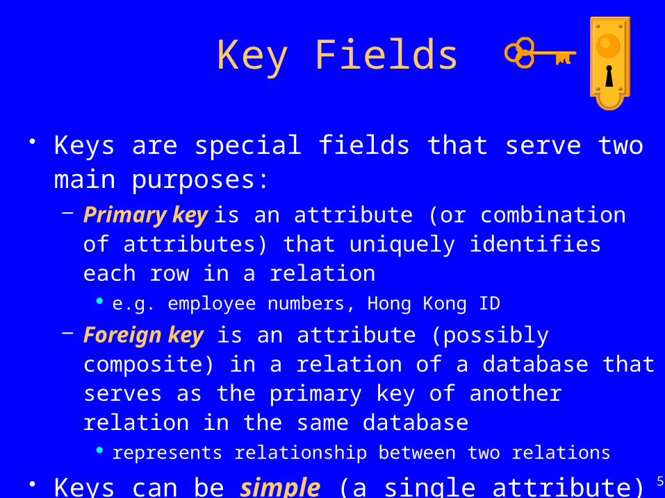
• Keys are special fields that serve two main purposes:– Primary key is an attribute (or combination of attributes) that
uniquely identifies each row in a relation e.g. employee numbers, Hong Kong ID
– Foreign key is an attribute (possibly composite) in a relation of a database that serves as the primary key of another relation in the same database
represents relationship between two relations
• Keys can be simple (a single attribute) or composite (more than one attribute)

6
Fig 4-3: Schema for four relations (Pine Valley Furniture)
Primary Key
Foreign Key
Combined, these are a composite primary key … individually they are foreign keys

7
Integrity Constraints• Included in relational data model to facilitate
maintaining the accuracy and integrity of data
• Domain Constraints– allowable values for an attribute– e.g. data type and size
• Entity Integrity– no primary key attribute may be null– all primary key fields must have data
• Referential Integrity– rule that states that either each foreign key value must match a
primary key value in another relation or the foreign key value must be null

8
Fig 4-5: Referential integrity constraints (Pine Valley Furniture)
Referential integrity constraints are
drawn via arrows from dependent to
parent table
Foreign key
9
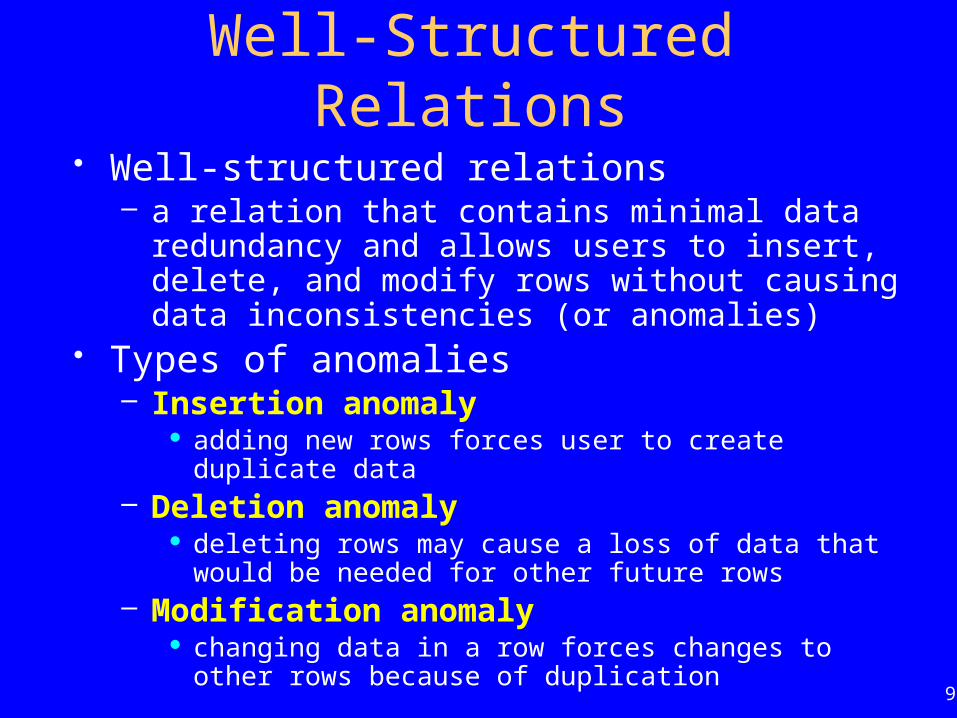
Well-Structured Relations
• Well-structured relations– a relation that contains minimal data redundancy and allows
users to insert, delete, and modify rows without causing data inconsistencies (or anomalies)
• Types of anomalies– Insertion anomaly
adding new rows forces user to create duplicate data– Deletion anomaly
deleting rows may cause a loss of data that would be needed for other future rows
– Modification anomaly changing data in a row forces changes to other rows because of
duplication

10
Example – Figure 4-2b
• Insertion – can’t enter a new employee without having the employee take a class.• Deletion – if we delete employee 140, we lose information about the existence of
a Tax Acc class.• Modification – giving a salary increase to employee 100 forces us to update
multiple records.

11
Example – Well-Structured RelationsEMPLOYEE1
EMP_COURSE

12
Transforming E-R Diagrams into Relations
1. Mapping Regular Entities to Relations – Simple attributes
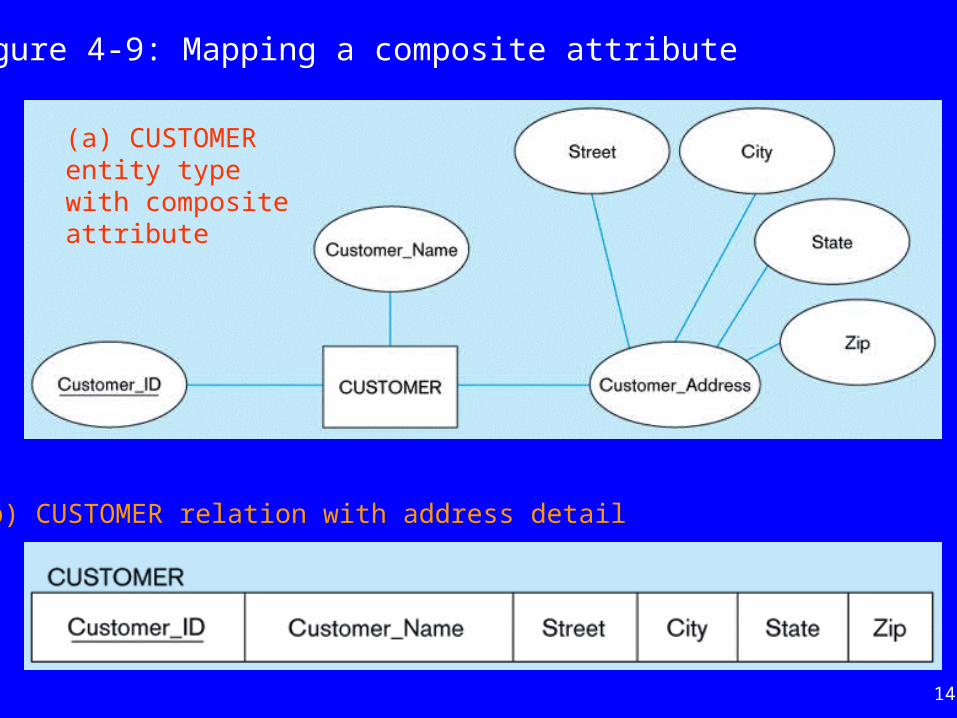
E-R attributes map directly onto the relation– Composite attributes
use only their simple, component attributes – Multi-valued attribute
becomes a separate relation with a foreign key taken from the original entity

13
(a) CUSTOMER entity type with simple attributes
Figure 4-8: Mapping a regular entity
(b) CUSTOMER relation
14
(a) CUSTOMER entity type with composite attribute
Figure 4-9: Mapping a composite attribute
(b) CUSTOMER relation with address detail

15
Figure 4-10: Mapping an entity with multi-valued attribute
Multi-valued attribute becomes a separate relation with foreign key

16
Transforming E-R Diagrams Into Relations
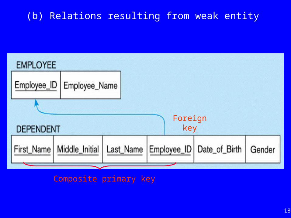
2. Mapping Weak Entities– becomes a separate relation with a foreign key
taken from the identifying entity– primary key composed of
partial identifier of weak entity primary key of identifying relation (strong entity)

17
Figure 4-11: Example of mapping a weak entity
(a) Weak entity DEPENDENT
18
(b) Relations resulting from weak entity
Foreign key
Composite primary key

19
Transforming E-R Diagrams Into Relations
3. Mapping Binary Relationships– One-to-Many
primary key on the one side becomes a foreign key on the many side
– Many-to-Many create a new relation with the primary keys of the two entities as
its primary key– One-to-One
primary key on the mandatory side becomes a foreign key on the optional side
avoids the need to store null values in the foreign key any attributes associated with the relationship are also included in
the same relation as the foreign key

20
Figure 4-12: Example of mapping a 1:M relationship
(a) Relationship between customers and orders
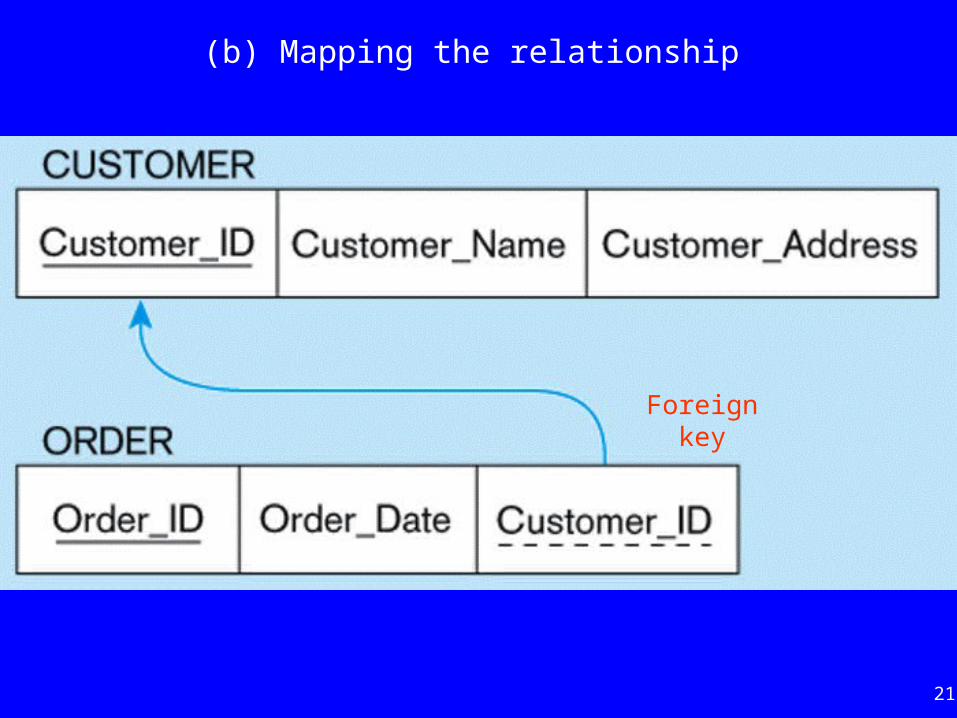
21
(b) Mapping the relationship
Foreign key

22
Figure 4-13: Example of mapping an M:N relationship
(a) Supplies relationship (M:N)
Note: The Supplies relationship will become a separate relation

23
(b) Three resulting relations
Create new relationForeign key
Foreign key
Composite primary key

24
Figure 4-14a: Mapping a binary 1:1 relationship
(a) Binary 1:1 relationship

25
(b) Resulting relations
Note: Nurse_in_Charge is another name for Nurse_ID. Attribute attached to relationship is stored with foreign key.

26
Transforming E-R Diagrams Into Relations
4. Mapping Associative Entities– Identifier not assigned
default primary key for the associative relation is the primary keys of the two entities
– Identifier assigned when it is natural and familiar to end-users default identifier may not uniquely identify
instances of the associative entity

27
Figure 4-15a: Mapping an associative entity with no assigned identifier

28
(b) Three resulting relations
Note: Default primary key for the associative relation is the primary keys of the two entities.

29
Figure 4-16: Mapping an associative entity with an identifier
(a) Associative entity (SHIPMENT)

30
(b) Three relations
Note: Customer_ID and Vendor_ID together do not uniquely identify the SHIPMENT relation.

31
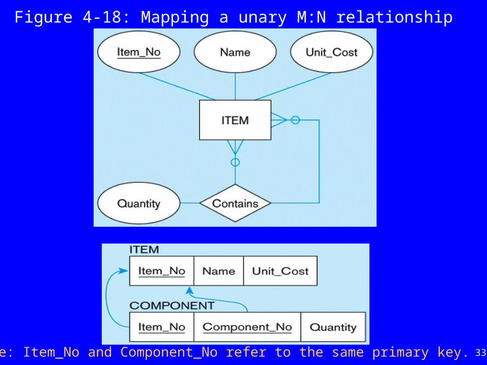
Transforming E-R Diagrams Into Relations
5. Mapping Unary Relationships– One-to-Many
recursive foreign key in the same relation a foreign key in a relation that references the primary key
values of that same relation
– Many-to-Many create two relations
– one for the entity type– one for an associative relation in which the primary key
has two attributes, both taken from the primary key of the entity

32
Figure 4-17: Mapping a unary 1:N relationship
Note: Manager_ID and Employee_ID refer to the same primary key of the relation. Manager_ID is a foreign key that references itself.
33
Figure 4-18: Mapping a unary M:N relationship
Note: Item_No and Component_No refer to the same primary key.

34
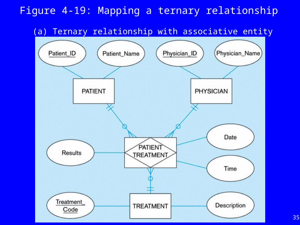
Transforming E-R Diagrams Into Relations
6. Mapping Ternary (and n-ary) relationships– one relation for each entity and one for the
associative entity– associative entity has foreign keys to each entity
in the relationship
35
Figure 4-19: Mapping a ternary relationship
(a) Ternary relationship with associative entity

36
(b) Mapping the ternary relationship
Is Patient_ID, Physician_ID, and Treatment_Code as composite key enough?

37
Transforming E-R Diagrams Into Relations
7. Mapping Supertype/Subtype relationships– a separate relation for supertype and each
subtype– supertype attributes (including identifier and
subtype discriminator) go into supertype relation– unique subtype attributes go into each subtype
relation; primary key of supertype relation also becomes primary key of subtype relation

38
Figure 4-20: Supertype/subtype relationships

39
Fig 4-21: Mapping supertype/subtype relationships to relations

40
Normalization
• primarily a tool to validate and improve a logical design so that it satisfies certain constraints that avoid unnecessary duplication of data
• process of decomposing relations with anomalies to produce smaller, well-structured relations
• based on analysis of functional dependencies

41
Functional Dependencies and Keys
• Functional Dependency– the value of one attribute (the determinant) determines
the value of another attribute e.g. In EMPLOYEE1 (Emp_ID, Name, Dept_Name, Salary);
Emp_ID -> Name, Dept_Name, Salary
• Candidate Key– a unique identifier– one of the candidate keys will become the primary key
e.g. there are both credit card number and HKID in a table; in this case both are candidate keys
– each non-key field is functionally dependent on every candidate key

42
Fig 4-22: Steps in normalization

43
First Normal Form
• No multi-valued attributes• Every attribute value is atomic• Fig. 4-2b is in 1st Normal form
– EMPLOYEE2 (Emp_ID, Name, Dept_Name, Salary, Course_Title, Date_Completed)
• All relations are in 1st Normal Form

44
Second Normal Form• 1NF plus every non-key attribute is fully
functionally dependent on the ENTIRE primary key– every non-key attribute must be defined by the
entire key, not by only part of the key– no partial functional dependencies
• Fig. 4-2b is NOT in 2nd Normal Form (see Fig. 4-23b)

45
Fig 4-23b: Functional Dependencies
Emp_ID Course_Title Date_CompletedSalaryDept_NameName
Dependency on entire primary key
Dependency on only part of the key
Emp_ID, Course_Title Date_Completed
Emp_ID Name, Dept_Name, Salary
Therefore, NOT in 2nd Normal Form!!
EMPLOYEE2

46
Getting it into 2nd Normal Form
Note: Decompose into two separate relations.
Emp_ID SalaryDept_NameName
Course_Title Date_CompletedEmp_ID
Both are full functional
dependenciesEMPLOYEE1
EMP_COURSE
47
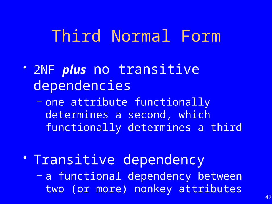
Third Normal Form
• 2NF plus no transitive dependencies– one attribute functionally determines a second,
which functionally determines a third
• Transitive dependency– a functional dependency between two (or more)
nonkey attributes

48
Figure: Relation with transitive dependency
(a) SALES relation with sample data
49
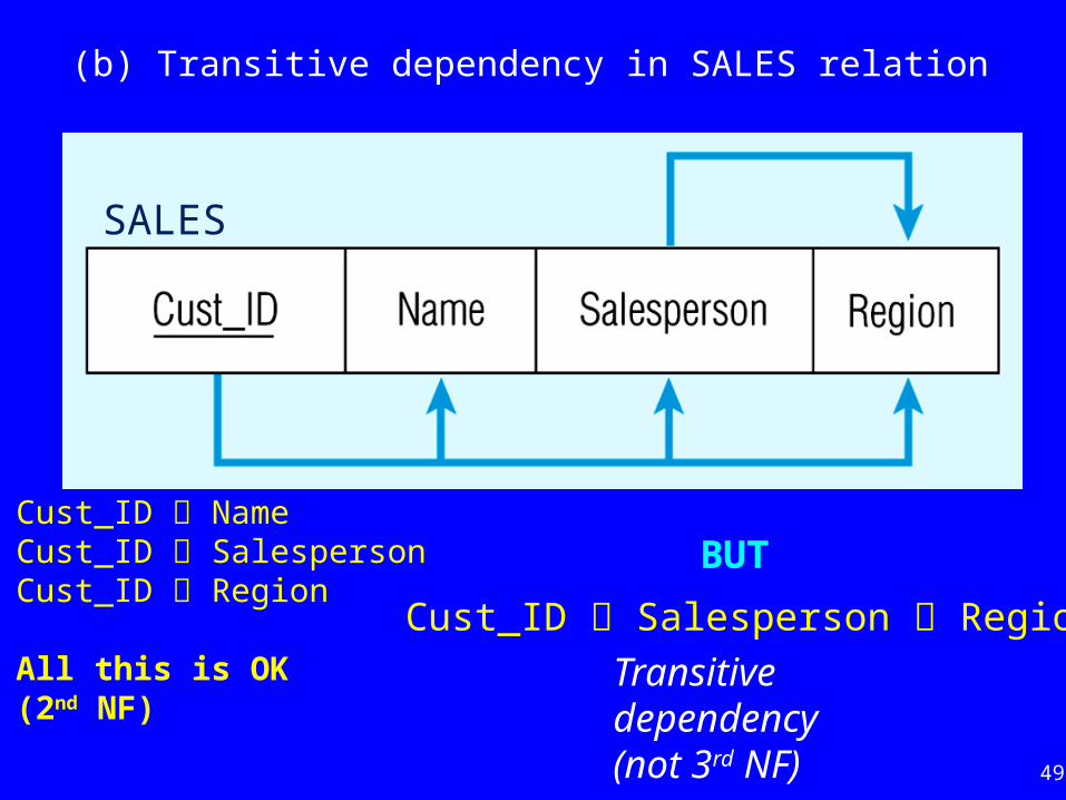
(b) Transitive dependency in SALES relation
Cust_ID NameCust_ID SalespersonCust_ID Region
All this is OK(2nd NF)
BUT
Cust_ID Salesperson Region
Transitive dependency(not 3rd NF)
SALES

50
Figure: Removing a transitive dependency
(a) Decomposing the SALES relation

51
(b) Relations in 3NF
Note: No transitive dependencies…both relations are in 3rd NF.
Cust_ID Name
Cust_ID Salesperson
Salesperson Region

52
Review Questions
• What is the relational data model?• What are key fields?• What are integrity constraints?• What are well-structured relations?• How to transform ER diagrams into relations?• What is normalization?• What are the 3 Normal Forms?
Related Documents


