Logic Families Digital Electronics Sandeep Kumar Singh BCA II nd Semester

Welcome message from author
This document is posted to help you gain knowledge. Please leave a comment to let me know what you think about it! Share it to your friends and learn new things together.
Transcript

Logic Families
Digital Electronics
Sandeep Kumar SinghBCA IInd Semester
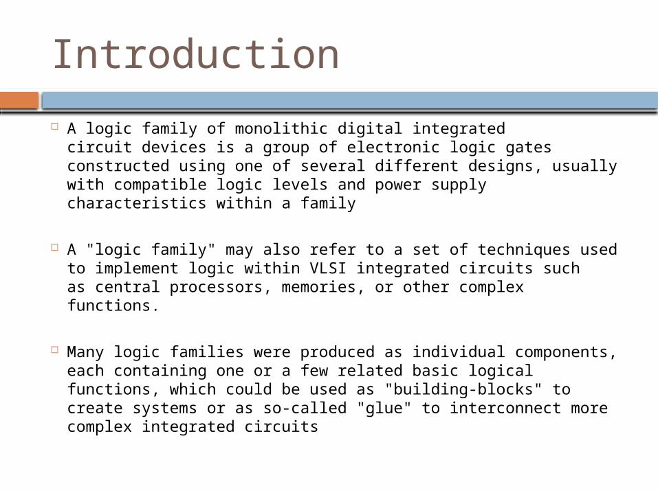
Introduction A logic family of monolithic digital integrated circuit devices is
a group of electronic logic gates constructed using one of several different designs, usually with compatible logic levels and power supply characteristics within a family
A "logic family" may also refer to a set of techniques used to implement logic within VLSI integrated circuits such as central processors, memories, or other complex functions.
Many logic families were produced as individual components, each containing one or a few related basic logical functions, which could be used as "building-blocks" to create systems or as so-called "glue" to interconnect more complex integrated circuits

Various Technologies Resistor–transistor logic (RTL)
Direct-coupled transistor logic (DCTL) Resistor–capacitor–transistor logic (RCTL)
Diode–transistor logic (DTL) Complemented transistor diode logic (CTDL) High-threshold logic (HTL)
Transistor–transistor logic (TTL) Emitter-coupled logic (ECL)
Positive emitter-coupled logic (PECL) Low-voltage positive emitter-coupled logic (LVPECL)
P-type metal–oxide–semiconductor logic (PMOS) N-type metal–oxide–semiconductor logic (NMOS) Complementary metal–oxide–semiconductor logic (CMOS) Integrated injection logic (I2L) Gunning Transceiver Logic (GTL)

RTL (Resistor-Transistor Logic) Developed at Fairchild Semiconductor for the Apollo Guidance
Computer in 1962
Built using resistors as the input network and bipolar junction transistors (BJTs) as switching devices
A variant with integrated capacitors, RCTL, had increased speed, but lower immunity to noise than RTL. This was made by Texas Instruments as their "51XX" series.
Special type of RTL gate known as the direct-coupled transistor logic (DCTL) gate is one wherein the bases of the transistors are connected directly to inputs without any base resistors.
RTL

Schematic of a one-transistor RTL NOR gate
RTL

RTL
Advantages• Involved a minimum number of transistors (which was an
important consideration before integrated circuit technology as transistors were the most expensive component to produce.)
• DCTL gates are more economical and simpler to fabricate onto integrated circuits than RTL

RTL
Limitations• The obvious disadvantage of RTL is its high power dissipation
when the transistor is switched on
• Bulkiness
• Low speed
• Limited fan-out
• Poor noise margin
• DCTL gates suffer from a phenomenon known as current hogging.

DTL
DTL (Diode-Transistor Logic)•DTL was made by Fairchild and Westinghouse
•Technology for designing and fabricating digital circuits wherein logic gates employ both diodes and transistors
•Diode logic goes back as far as ENIAC and was used in many early vacuum tube computers
•Logic gating function (e.g., AND) is performed by a diode network and the amplifying function is performed by a transistor (contrast this with RTL and TTL)
•The DTL propagation delay is relatively large
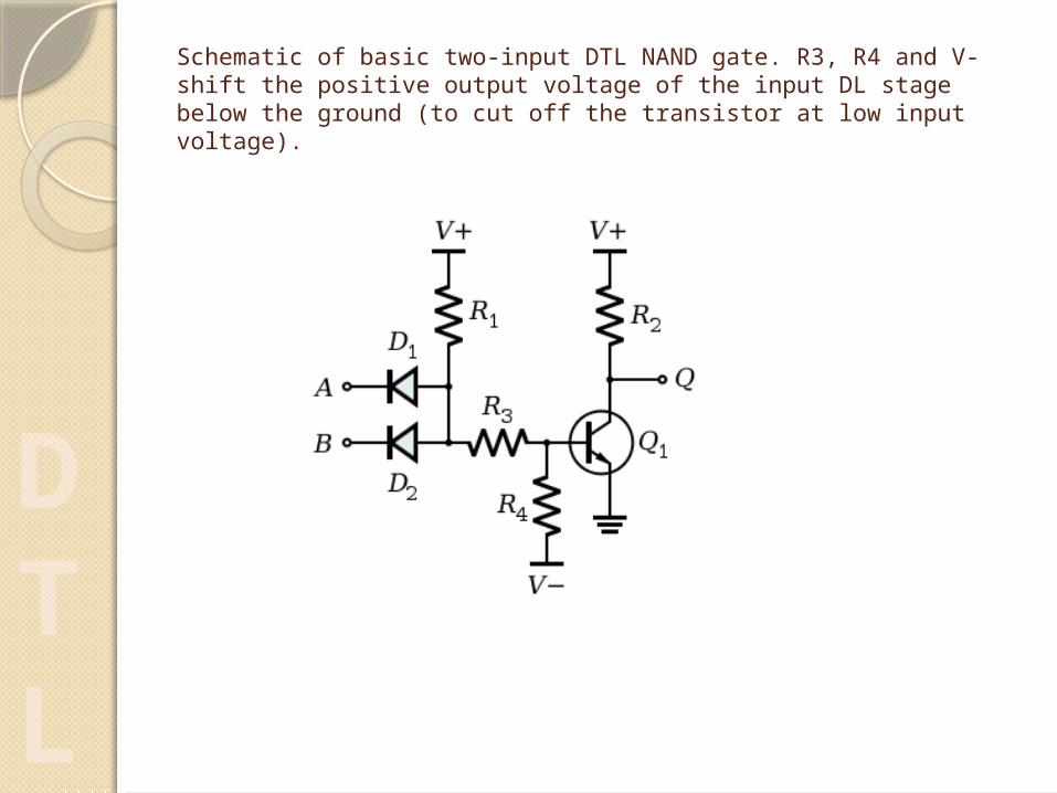
Schematic of basic two-input DTL NAND gate. R3, R4 and V- shift the positive output voltage of the input DL stage below the ground (to cut off the transistor at low input voltage).
DTL
AdvantagesOffers better noise margins than
RTL Greater fan-outs than RTL
DTL
LimitationsThe obvious disadvantage of RTL
is its high power dissipation when the transistor is switched on
low speed,specially in comparison to TTLD
TL

TTL (Transistor Transistor Logic) Built from bipolar junction transistors (BJT)
and resistors.
It is called transistor–transistor logic because both the logic gating function (e.g., AND) and the amplifying function are performed by transistors
TTL is notable for being a widespread integrated circuit (IC) family used in many applications such as computers, industrial controls, test equipment and instrumentation, consumer electronics, synthesizers).
TTL
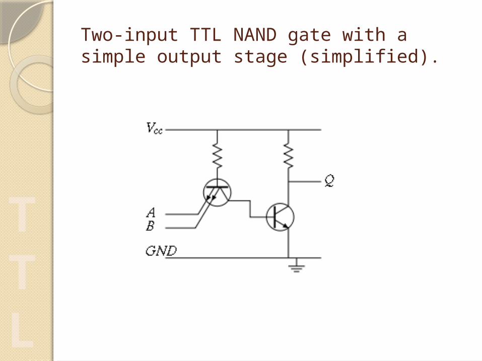
Two-input TTL NAND gate with a simple output stage (simplified).
TTL

Advantages TTL is less sensitive to damage
from electrostatic discharge than early CMOS devices
Compared to Contemporary ECL circuits, TTL uses less power and has easier design rules.
TTL is particularly well suited to bipolar integrated circuits because additional inputs to a gate merely required additional emitters on a shared base region of the input transistor
TTL
Limitations TTL devices consume substantially more
power than equivalent CMOS devices at rest, but power consumption does not increase with clock speed as rapidly as for CMOS devices
Substantially slower than ECL
Due to the output structure of TTL devices, the output impedance is asymmetrical between the high and low state, making them unsuitable for driving transmission lines
TTL
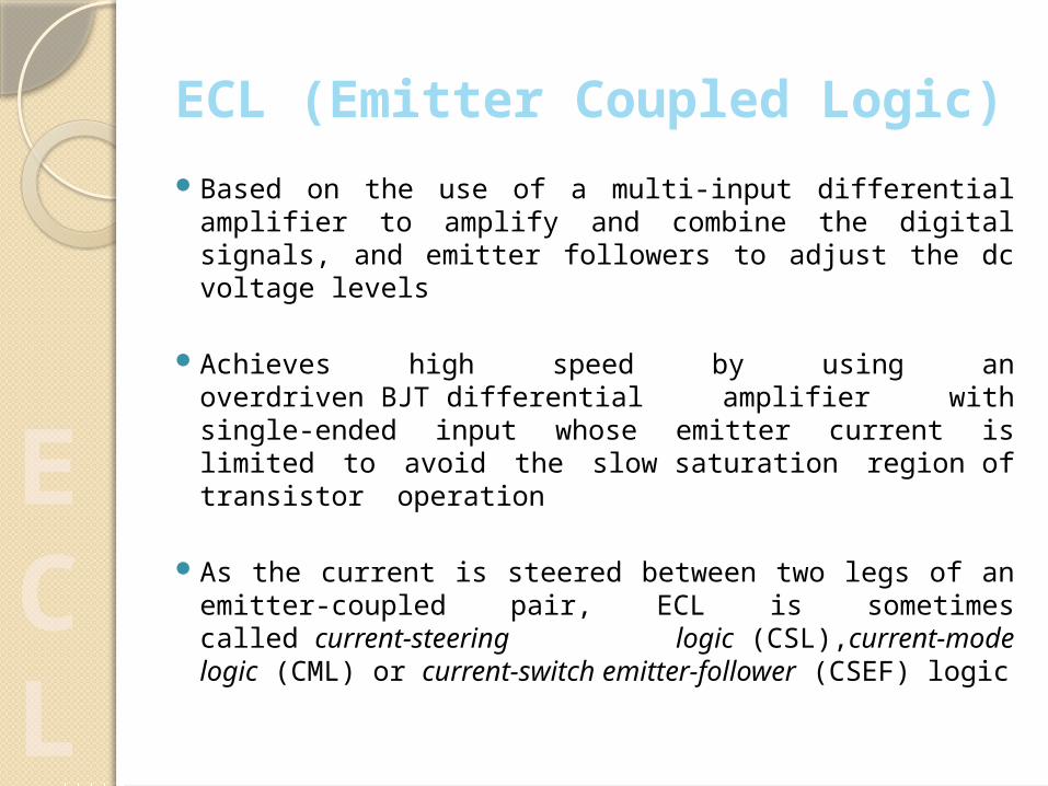
ECL (Emitter Coupled Logic) Based on the use of a multi-input differential
amplifier to amplify and combine the digital signals, and emitter followers to adjust the dc voltage levels
Achieves high speed by using an overdriven BJT differential amplifier with single-ended input whose emitter current is limited to avoid the slow saturation region of transistor operation
As the current is steered between two legs of an emitter-coupled pair, ECL is sometimes called current-steering logic (CSL),current-mode logic (CML) or current-switch emitter-follower (CSEF) logic
ECL

Motorola ECL 10,000 basic gate circuit diagram
ECL
AdvantagesChanges state quickly
Low gate delay
High Fan out
Constant current draw of the differential amplifiers minimizes delays and glitches due to supply-line inductance and capacitance
ECL
LimitationsEach gate continuously draws
current, which means it requires (and dissipates) significantly more power than those of other logic families, especially when quiescent.
ECL suffers from small noise margins, which can be troublesome
ECL

NMOS Uses n-type metal-oxide-semiconductor field
effect transistors (MOSFETs) to implement logic gates and other digital circuits
NMOS transistors have four modes of operation: cut-off (or sub-threshold), triode, saturation (sometimes called active), and velocity saturation
Better (and the most common) way to make the gates faster is to use depletion-mode transistors instead of enhancement-mode transistors as loads. This is called depletion-load NMOS logic
NMOS
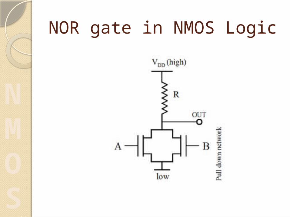
NOR gate in NMOS Logic
NMOS

AdvantagesMuch faster than comparable
PMOS and CMOS circuits
Easier to manufacture NMOS than CMOS
NMOS

LimitationsThe major problem with NMOS (and most
other logic families) is that a DC current must flow through a logic gate even when the output is in a steady state (low in the case of NMOS)
Slow to transition from low to high
The asymmetric input logic levels make NMOS circuits somewhat susceptible to noise
NMOS
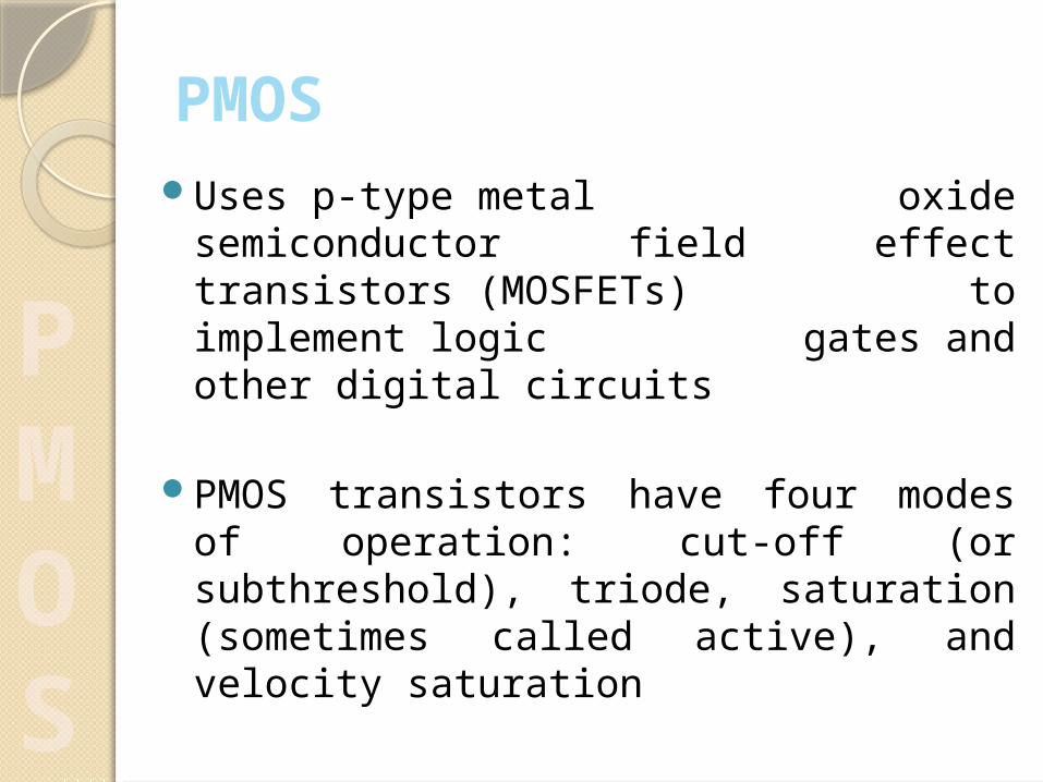
PMOSUses p-type metal oxide
semiconductor field effect transistors (MOSFETs) to implement logic gates and other digital circuits
PMOS transistors have four modes of operation: cut-off (or subthreshold), triode, saturation (sometimes called active), and velocity saturation
PMOS
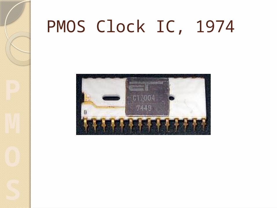
PMOS Clock IC, 1974
PMOS

AdvantagesPMOS logic is easy to design and
manufacture
PMOS

Limitations DC current flows through a PMOS logic gate when the
PUN(pull up network) is active, that is whenever the output is high. This leads to static power dissipation even when the circuit sits idle
PMOS circuits are slow to transition from high to low
Using a resistor of lower value will speed up the process but also increases static power dissipation
The asymmetric input logic levels make PMOS circuits susceptible to noise
PMOS

CMOS CMOS circuits were invented by Frank Wanlass of Fairchild
Semiconductor in 1963, although the first CMOS I.C.'s were not produced until 1968, this time at RCA
Technology for designing and fabricating integrated circuits that employ logic using both n- and p-channel MOSFET's
CMOS is the other major technology utilized in manufacturing digital IC's aside from TTL
CMOS technology is also used for several analog circuits such as image sensors(CMOS sensor), data converters, and highly integrated transceivers for many types of communication
CMOS

CMOS Invertor (NOT Logic Gate)
CMOS
Advantages High noise immunity
Low static power consumption
Do not produce as much waste heat as other forms of logic
Allows a high density of logic functions on a chip. It was primarily for this reason that CMOS became the most used technology to be implemented in VLSI chips
CMOS

LimitationsCMOS circuits are quite
vulnerable to ESD damage. Because of this issue, modern CMOS IC's are now equipped with on-chip ESD protection circuits, which reduce (but not totally eliminate) risks of ESD damage
CMOS

IIL (Integrated Injection Logic) Class of digital circuits built with multiple collector
bipolar junction transistors
When introduced it had speed comparable to TTL yet was almost as low power as CMOS, making it ideal for use in VLSI (and larger) integrated circuits
IIL is relatively simple to construct on an integrated circuit
Logic voltage levels are very close (High: 0.7V, Low: 0.2V), I2L has high noise immunity because it operates by current instead of voltage. Sometimes also known as Merged Transistor Logic
IIL

Integrated Injection Logic Circuit
IIL

GTL (Gunning transceiver Logic)
Invented by William Gunning while working for Xerox at the Palo Alto Research Center
GTL is a type of logic signaling used to drive electronic backplane buses
It has a voltage swing between 0.4 volts and 1.2 volts—much lower than that used in TTL and CMOS logic—and symmetrical parallel resistive termination
All Intel front-side buses use GTL.
GTL

Monolithic integrated circuit logic families table
FamilyDescriptio
nPropagation delay (ns)
Toggle speed (MHz)
Power per gate
@1 MHz (mW)
Typical supply
voltage V (range)
Introduction year Remarks
TTL F 3.5 100 5.4 5 (4.75-5.25)
1979 Fast
TTL AS 2 105 8 5 (4.5-5.5) 1980 Advanced Schottky
TTL S 3 110 19 5 (4.75-5.25)
1969 Schottky high speed
TTL G 1.5 1125 (1.125 GHz)
1.65 - 3.6 2004 First GHz 7400 series
logicTTL Original
series10 25 10 5 (4.75-
5.25)1964 Several
manufacturers
TTL LS 10 33 2 5 (4.75-5.25)
1976 Low power Schottky
high speedTTL H 6 43 22 5 (4.75-
5.25)1964 High speed
TTL ALS 4 34 1.3 5 (4.5-5.5) 1976 Advanced Low power Schottky
TTL L 33 3 1 5 (4.75-5.25)
1964 Low power…continued to next Slide
COMPARITIVE
CHART

Family Description
Propagation delay
(ns)
Toggle speed (MHz)
Power per gate
@1 MHz (mW)
Typical supply
voltage V (range)
Introduction year Remarks
RTL Resistor–transistor logic
4 10 3.3 1963 the first CPU built
from integrated
circuits (the Apollo Guidance
Computer) used RTL.
ECL MECL I 8 31 -5.2 1962 first integrated
logic circuit
commercially
producedECL ECL 100K 0.75 350 40 -4.5(-4.2 - -
5.2)1981
ECL ECL 100KH 1 250 25 -5.2(-4.9 - -5.5)
1981
ECL ECL III 1 500 60 -5.2(-5.19 - -5.21)
1968 Improved ECL
Monolithic integrated circuit logic families table (..continued)
…continued to next Slide
COMPARITIVE
CHART

FamilyDescriptio
n
Propagation delay
(ns)
Toggle speed (MHz)
Power per gate
@1 MHz (mW)
Typical supply
voltage V (range)
Introduction year Remarks
ECL ECL 10K 2 125 25 -5.2(-5.19 - -5.21)
1971 Motorola
DTL Diode–transistor
logic
10 5 1962 Introduced by
Signetics, Fairchild 930 line became industry
standard in 1964
CMOS HC/HCT 9 30 0.5 5 (2-6 or 4.5-5.5)
1982 HCT has TTL
compatible levels
CMOS AC/ACT 3 125 0.5 3.3 or 5 (2-6 or 4.5-
5.5)
1985 ACT has TTL
Compatible levels
CMOS 4000B/74C 30 5 1.2 10V (3-18) 1970 Approximately half
speed and power at 5
volts
Monolithic integrated circuit logic families table (..continued)
COMPARITIVE
CHART

NEW
WORDS
Fan out - fan-out of a gate is the ability of its output to drive several other gates. The more gates it can drive, the higher is its fan-out
Gate Delay - Gate delay is the delay offered by a gate for the signal appearing at its input, before it reaches the gate output
Noise Margin - Undesirable voltage variations that are superimposed on normal operating voltage levels are called noise. All gates are designed to tolerate a certain amount of noise on their input and output ports. The maximum noise voltage level that is tolerated by a gate is called noise margin
Propagation Delay - The time between the logic transition on an input and the corresponding logic transition on the output of the logic gate
Basic Concepts

Sources of Information
Wikipedia, the free encyclopedia
www.play-hookey.com/digital/electronics
http://www.asic-world.com/digital/seq.html
www.siliconfareast.com

Thank You
Related Documents