Log Periodic FM Broadcast Antenna Model 6025 Single-Boom Instruction Manual Installation, Operation, & Maintenance

Welcome message from author
This document is posted to help you gain knowledge. Please leave a comment to let me know what you think about it! Share it to your friends and learn new things together.
Transcript

Log PeriodicFM Broadcast Antenna
Model 6025 Single-Boom
Instruction Manual
Installation, Operation, & Maintenance

Congratulations! Thank you for purchasing one of the finest FM broadcast antennas on the market today. The Shively Labs Model 6025 is the top-of-the-line in its class for its simplicity, superior performance and durability.
Your purchase is backed by the best technical support in the industry. Shively is a leading manufacturer in the broadcast industry, providing an extensive range of antennas, transmission line and components. Our technical staff has a wealth of experience in the broadcast industry and is standing by to serve you in any way.
This manual is intended to give you a good basic understanding of your antenna: its proper and safe installation, startup, and operation, and trouble-shooting and maintenance information to keep it working satisfactorily for years to come. Please have everyone involved with the antenna read this manual carefully, and keep it handy for future reference.
Meanwhile, please feel free to contact your sales representative at Shively Labs at any time if you need information or help. Call or write:
Publication No. im-6025_single (140108)

IMPORTANT
Please read this manual in its entirety before beginning installation of your antenna!
Failure to follow the installation and operation instructions in this manual could lead to failure of your
equipment and might even void your warranty!


Table of Contents
Chapter 1 Preparation........................................................................1Check the shipment............................................................................... 1Check the parts..................................................................................... 1Prepare the mounting location. .............................................................. 1
Figure 1 Tower layout, single-boom antenna .................................... 2Torque specifications............................................................................. 3
Table 1 Torque specifications .......................................................... 3Chapter 2 Assembly & Installation.....................................................5
Assemble the antenna bay..................................................................... 5Figure 2 Arms attached to booms .................................................... 5Figure 3 Mounting plates attached to booms .................................... 6Figure 4 Cable clamp clip & cable clamp, installed............................. 6Figure 5 Vertical mounting position.................................................. 7Figure 6 Horizontal mounting position.............................................. 8Figure 7 Angled mounting position................................................... 8Figure 8 Clamp halves, installed (tower leg or mounting pole
up to 3-1/2" diameter) ...................................................... 9Figure 9 Clamp halves, installed (tower leg or mounting pole
3-1/2" to 5-1/4" diameter) ................................................. 9Attach the boom supports.................................................................... 10
Figure 10 Fiberglass angle installation............................................ 10Figure 11 Vertical boom support installation ................................... 11Figure 12 Horizontal boom support, installed .................................. 12Figure 13 Vertical boom support channel installation (tower leg
or mounting pole up to 3-1/2" diameter) .......................... 13Figure 14 Vertical boom support channel installation (tower leg
or mounting pole 3-1/2" to 5-1/4" diameter) ..................... 13Mount the antenna bay on the pole or tower......................................... 14
Figure 15 Bay and vertical support, installed................................... 14Figure 16 Horizontal support channel, installed............................... 15Figure 17 Cut and attach the horizontal support. ............................ 16
Repeat for additional bays. .................................................................. 16Connect the antenna to the transmitter. ............................................... 17
Figure 18 Remove the flange cover................................................ 17Figure 19 Connect the coax to the flange. ...................................... 18
Chapter 3 Assembly & Installation (with radomes).........................19Assemble the antenna bay................................................................... 19
Figure 20 Arms attached to booms ................................................ 19Figure 21 Mounting plates attached to booms ................................ 20Figure 22 Square plug installation.................................................. 20Figure 23 Cable clamp clip & cable clamp, installed......................... 21Figure 24 Vertical mounting position .............................................. 22Figure 25 Horizontal mounting position .......................................... 22Figure 26 Angled mounting position............................................... 23
i

Table of Contents
(continued)
Figure 27 Clamp halves, installed (tower leg or mounting pole up to 3-1/2" diameter) ............................................. 24Figure 28 Clamp halves, installed (Tower leg or mounting pole 3-1/2" to 5-1/4" diameter)........................................ 24
Install the radomes. ............................................................................ 25Figure 29 Radome installation ....................................................... 26Figure 30 Sealing summary ........................................................... 27
Attach the boom supports.................................................................... 27Figure 31 Fiberglass angle installation............................................ 28Figure 32 Vertical boom support installation ................................... 29Figure 33 Horizontal boom support, installed .................................. 30Figure 34 Vertical boom support channel installation (tower leg or
mounting pole up to 3-1/2" diameter) .............................. 31Figure 35 Vertical boom support channel installation (tower leg or
mounting pole 3-1/2" to 5-1/4" diameter) ......................... 31Mount the antenna bay on the pole or tower......................................... 32
Figure 36 Bay and vertical support, installed................................... 32Figure 37 Horizontal support channel, installed............................... 33Figure 38 Cut and attach the horizontal support. ............................ 33
Drill drain holes in radome ................................................................... 34Figure 39 Drain hole locations ....................................................... 34
Repeat for additional bays. .................................................................. 34Connect the antenna to the transmitter. ............................................... 35
Figure 40 Remove the flange cover................................................ 35Figure 41 Connect the coax to the flange. ...................................... 36
Chapter 4 Power Divider Installation...............................................37Mount the power divider...................................................................... 37
Figure 42 Power divider installed and connected............................. 37Connect the feedline cables. ................................................................ 38
Figure 43 Remove the flange cover on each antenna bay. ............... 38Figure 44 Connect the coax to the flange. ...................................... 39
Connect the transmission line to the power divider. ............................... 39Chapter 5 Startup.............................................................................41
Optimize VSWR................................................................................... 41Figure 45 Power up your antenna.................................................. 41
Operate.............................................................................................. 41Chapter 6 Troubleshooting...............................................................43
Broad spectrum RF noise ..................................................................... 43High VSWR ........................................................................................ 43Change in coverage ............................................................................ 43
Chapter 7 Maintenance ....................................................................45Log ................................................................................................... 45Inspection ......................................................................................... 45Paint ................................................................................................. 45
ii
Table of Contents
(continued)
Return Policy ..................................................................................... 45Chapter 8 Parts ................................................................................47Parts list ............................................................................................. 47Table 2 Parts list ......................................................................... 47
iii

Preparation
1 Preparation
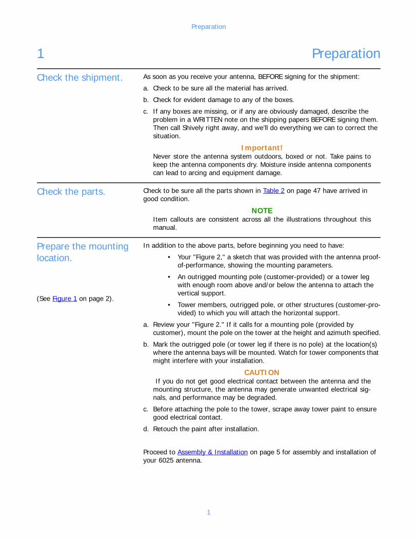
Check the shipment. As soon as you receive your antenna, BEFORE signing for the shipment:
a. Check to be sure all the material has arrived.
b. Check for evident damage to any of the boxes.
c. If any boxes are missing, or if any are obviously damaged, describe the problem in a WRITTEN note on the shipping papers BEFORE signing them. Then call Shively right away, and we’ll do everything we can to correct the situation.
Important!Never store the antenna system outdoors, boxed or not. Take pains to keep the antenna components dry. Moisture inside antenna components can lead to arcing and equipment damage.
Check the parts. Check to be sure all the parts shown in Table 2 on page 47 have arrived in good condition.
NOTEItem callouts are consistent across all the illustrations throughout this manual.
Prepare the mounting location.
In addition to the above parts, before beginning you need to have:
• Your "Figure 2," a sketch that was provided with the antenna proof-of-performance, showing the mounting parameters.
• An outrigged mounting pole (customer-provided) or a tower leg with enough room above and/or below the antenna to attach the vertical support.
• Tower members, outrigged pole, or other structures (customer-pro-vided) to which you will attach the horizontal support.
a. Review your "Figure 2." If it calls for a mounting pole (provided by customer), mount the pole on the tower at the height and azimuth specified.
b. Mark the outrigged pole (or tower leg if there is no pole) at the location(s) where the antenna bays will be mounted. Watch for tower components that might interfere with your installation.
CAUTION If you do not get good electrical contact between the antenna and the mounting structure, the antenna may generate unwanted electrical sig-nals, and performance may be degraded.
c. Before attaching the pole to the tower, scrape away tower paint to ensure good electrical contact.
d. Retouch the paint after installation.
Proceed to Assembly & Installation on page 5 for assembly and installation of your 6025 antenna.
(See Figure 1 on page 2).
1

Preparation
Figure 1. Tower layout, single-boom antenna
2
Preparation
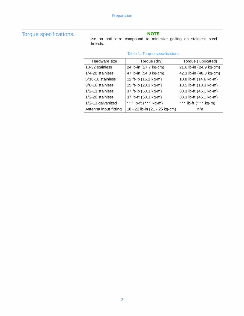
Torque specifications. NOTEUse an anti-seize compound to minimize galling on stainless steel threads.
Table 1. Torque specifications
Hardware size Torque (dry) Torque (lubricated)10-32 stainless 24 lb-in (27.7 kg-cm) 21.6 lb-in (24.9 kg-cm)1/4-20 stainless 47 lb-in (54.3 kg-cm) 42.3 lb-in (48.8 kg-cm)5/16-18 stainless 12 ft-lb (16.2 kg-m) 10.8 lb-ft (14.6 kg-m)3/8-16 stainless 15 ft-lb (20.3 kg-m) 13.5 lb-ft (18.3 kg-m)1/2-13 stainless 37 ft-lb (50.1 kg-m) 33.3 lb-ft (45.1 kg-m)1/2-20 stainless 37 lb-ft (50.1 kg-m) 33.3 lb-ft (45.1 kg-m)1/2-13 galvanized *** lb-ft (*** kg-m) *** lb-ft (*** kg-m)Antenna input fitting 18 - 22 lb-in (21 - 25 kg-cm) n/a
3


Assembly & Installation
2 Assembly & Installation
Assemble the antenna bay.
NOTEThe arms are different lengths - be sure to locate them with the longest nearest the base of the boom assembly as shown.
a. Attach arms (Figure 2, 1) to the boom assembly (2) using hardware (3, 4, 5).
NOTEIf necessary, use a small Phillips screwdriver to push the coax inside the boom out of the way when inserting the arms.
Figure 2. Arms attached to booms
5

Assembly & Installation
b. Attach mounting plate halves (Figure 3, 6 & 7) to booms using hardware (8, 9, 10, 11).
Figure 3. Mounting plates attached to booms
c. Attach the cable clamp (Figure 4, 12) to the cable clamp clip (13), using hardware (14, 15, 16, 17).
d. Attach the cable clamp clip to the top mount plate half (6) using hardware (18, 15, 16, 17).
e. Secure the cable section extending from the boom, using the cable clamp.
Figure 4. Cable clamp clip & cable clamp, installed
6

Assembly & Installation
NOTEOrient the antenna arms in either the vertical (Figure 5), horizontal (Fig-ure 6), or an angled (Figure 7) mounting position, as specified in your "Figure 2."
f. (Tower leg or mounting pole up to 3-1/2" diameter only) Using four threaded rods (19), attach two mount channels (20) to the mount plates as shown, with hardware (21, 22, 23).
g. (Tower leg or mounting pole 3-1/2" to 5-1/4" diameter only) Using four 1/2-13 x 1-1/2" bolts (24), attach two mount channels (20) to the mount plates as shown, with hardware (21, 22, 23).
Figure 5. Vertical mounting position
NOTEStandard mount plates include bolt holes for vertical, horizontal, and 45° angled mounting. For angles other than 45° (see Figure 7), only the required bolt holes will be present.
7

Assembly & Installation
Figure 6. Horizontal mounting position
Figure 7. Angled mounting position
8
Assembly & Installation
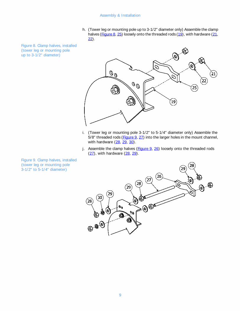
h. (Tower leg or mounting pole up to 3-1/2" diameter only) Assemble the clamp halves (Figure 8, 25) loosely onto the threaded rods (19), with hardware (21, 22).
Figure 8. Clamp halves, installed (tower leg or mounting pole up to 3-1/2" diameter)
i. (Tower leg or mounting pole 3-1/2" to 5-1/4" diameter only) Assemble the 5/8" threaded rods (Figure 9, 27) into the larger holes in the mount channel, with hardware (28, 29, 30).
j. Assemble the clamp halves (Figure 9, 26) loosely onto the threaded rods (27), with hardware (28, 29).
Figure 9. Clamp halves, installed (tower leg or mounting pole 3-1/2" to 5-1/4" diameter)
9

Assembly & Installation
Attach the boom supports.
NOTEFiberglass angles may be located on the opposite side of the boom from that shown – or on the bottom – as dictated by best fit to the tower.
a. Attach the two fiberglass angles (Figure 10, 31) to the booms using hardware (32, 33, 4, 5).
Figure 10. Fiberglass angle installation
10
Assembly & Installation
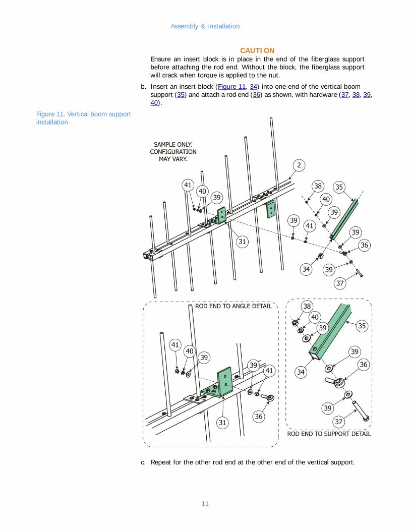
CAUTIONEnsure an insert block is in place in the end of the fiberglass support before attaching the rod end. Without the block, the fiberglass support will crack when torque is applied to the nut.
b. Insert an insert block (Figure 11, 34) into one end of the vertical boom support (35) and attach a rod end (36) as shown, with hardware (37, 38, 39, 40).
Figure 11. Vertical boom support installation
c. Repeat for the other rod end at the other end of the vertical support.
11
Assembly & Installation
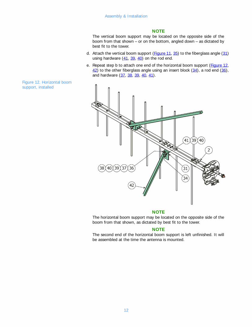
NOTEThe vertical boom support may be located on the opposite side of the boom from that shown – or on the bottom, angled down – as dictated by best fit to the tower.
d. Attach the vertical boom support (Figure 11, 35) to the fiberglass angle (31) using hardware (41, 39, 40) on the rod end.
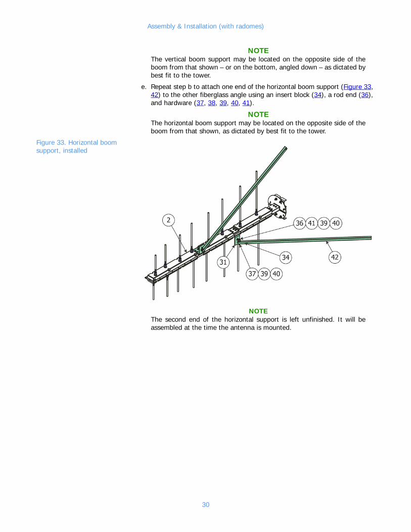
e. Repeat step b to attach one end of the horizontal boom support (Figure 12, 42) to the other fiberglass angle using an insert block (34), a rod end (36), and hardware (37, 38, 39, 40, 41).
Figure 12. Horizontal boom support, installed
NOTEThe horizontal boom support may be located on the opposite side of the boom from that shown, as dictated by best fit to the tower.
NOTEThe second end of the horizontal boom support is left unfinished. It will be assembled at the time the antenna is mounted.
12
Assembly & Installation
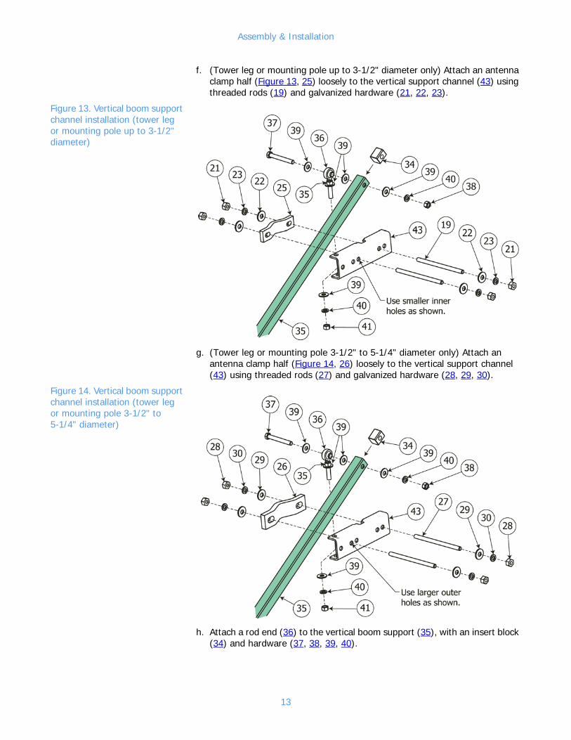
f. (Tower leg or mounting pole up to 3-1/2" diameter only) Attach an antenna clamp half (Figure 13, 25) loosely to the vertical support channel (43) using threaded rods (19) and galvanized hardware (21, 22, 23).
Figure 13. Vertical boom support channel installation (tower leg or mounting pole up to 3-1/2" diameter)
g. (Tower leg or mounting pole 3-1/2" to 5-1/4" diameter only) Attach an antenna clamp half (Figure 14, 26) loosely to the vertical support channel (43) using threaded rods (27) and galvanized hardware (28, 29, 30).
Figure 14. Vertical boom support channel installation (tower leg or mounting pole 3-1/2" to 5-1/4" diameter)
h. Attach a rod end (36) to the vertical boom support (35), with an insert block (34) and hardware (37, 38, 39, 40).
13

Assembly & Installation
i. Attach the rod end to the vertical support channel at the outer end of the vertical boom support using hardware (41, 39, 40).
NOTEDo not attach the support channel to the horizontal boom support (42) at this time.
Mount the antenna bay on the pole or tower.
CAUTION If you don’t get good electrical contact between the antenna and the mounting structure, the antenna may generate unwanted electrical sig-nals, and performance may be degraded.
a. Before mounting the antenna, scrape away any paint on the tower legs or mounting pole to ensure good electrical contact.
b. Mount the bay on the tower leg or outrigged pole at the location you marked, attaching the mount channels (Figure 15, 20) and the vertical support channel (43) to the mounting pole above the antenna bay.
c. Adjust the vertical boom support (35) on the tower leg or pole to level the bay.
d. (Tower leg or mounting pole up to 3-1/2" diameter only) Tighten the galvanized hardware (21, 22, 23) on the mount channel clamp halves (25) and the vertical support channel clamp half, tightly enough to support the antenna bay but loosely enough to allow azimuth adjustment.
Figure 15. Bay and vertical support, installed
14
Assembly & Installation
e. (Tower leg or mounting pole 3-1/2" to 5-1/4" diameter only) Tighten the galvanized hardware (28, 29, 30) on the mount channel clamp halves (26) and the vertical support channel clamp half, tightly enough to support the antenna bay but loosely enough to allow azimuth adjustment.
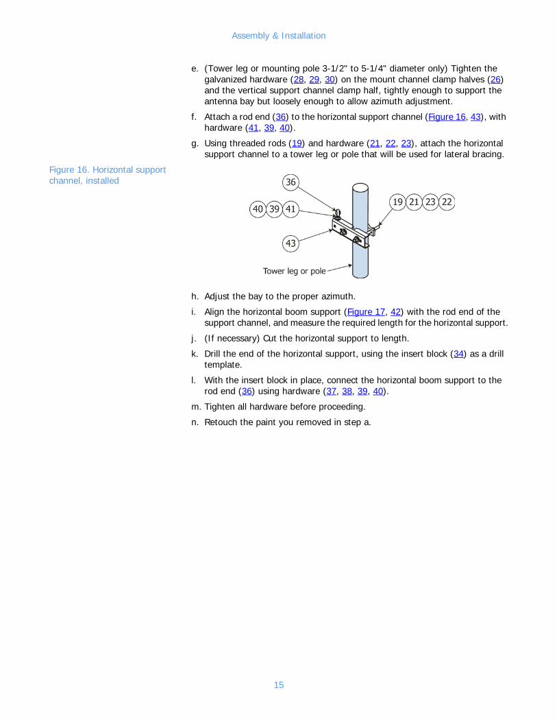
f. Attach a rod end (36) to the horizontal support channel (Figure 16, 43), with hardware (41, 39, 40).
g. Using threaded rods (19) and hardware (21, 22, 23), attach the horizontal support channel to a tower leg or pole that will be used for lateral bracing.
Figure 16. Horizontal support channel, installed
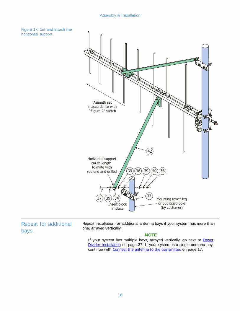
h. Adjust the bay to the proper azimuth.
i. Align the horizontal boom support (Figure 17, 42) with the rod end of the support channel, and measure the required length for the horizontal support.
j. (If necessary) Cut the horizontal support to length.
k. Drill the end of the horizontal support, using the insert block (34) as a drill template.
l. With the insert block in place, connect the horizontal boom support to the rod end (36) using hardware (37, 38, 39, 40).
m. Tighten all hardware before proceeding.
n. Retouch the paint you removed in step a.
15
Assembly & Installation
Figure 17. Cut and attach the horizontal support.
Repeat for additional bays.
Repeat installation for additional antenna bays if your system has more than one, arrayed vertically.
NOTEIf your system has multiple bays, arrayed vertically, go next to Power Divider Installation on page 37. If your system is a single antenna bay, continue with Connect the antenna to the transmitter. on page 17.
16
Assembly & Installation
Connect the antenna to the transmitter.
CAUTIONThe antenna is non-pressurized. If you are using pressurized cable, you must install a gas stop at the antenna input flange.
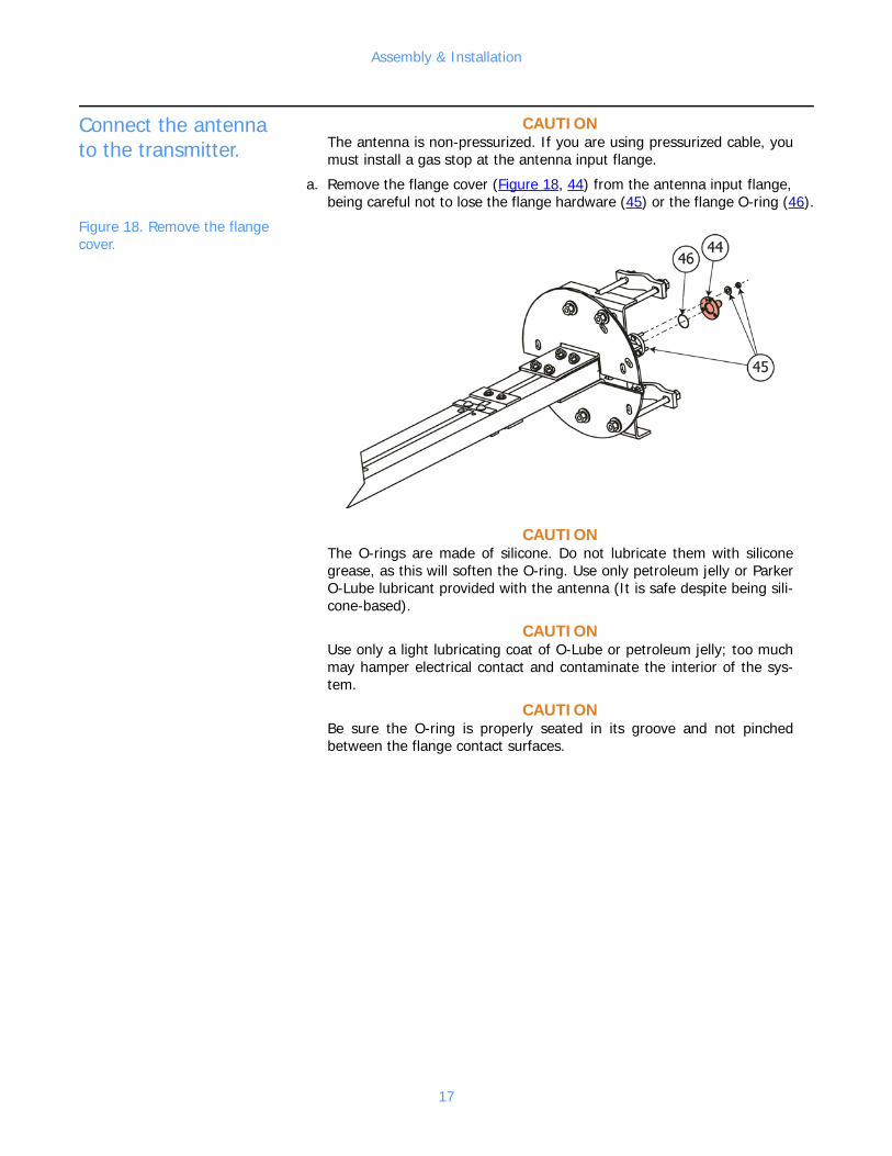
a. Remove the flange cover (Figure 18, 44) from the antenna input flange, being careful not to lose the flange hardware (45) or the flange O-ring (46).
Figure 18. Remove the flange cover.
CAUTIONThe O-rings are made of silicone. Do not lubricate them with silicone grease, as this will soften the O-ring. Use only petroleum jelly or Parker O-Lube lubricant provided with the antenna (It is safe despite being sili-cone-based).
CAUTIONUse only a light lubricating coat of O-Lube or petroleum jelly; too much may hamper electrical contact and contaminate the interior of the sys-tem.
CAUTIONBe sure the O-ring is properly seated in its groove and not pinched between the flange contact surfaces.
17
Assembly & Installation
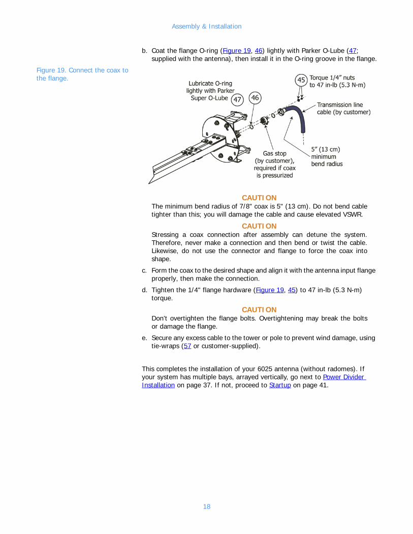
b. Coat the flange O-ring (Figure 19, 46) lightly with Parker O-Lube (47; supplied with the antenna), then install it in the O-ring groove in the flange.
Figure 19. Connect the coax to the flange.
CAUTIONThe minimum bend radius of 7/8" coax is 5" (13 cm). Do not bend cable tighter than this; you will damage the cable and cause elevated VSWR.
CAUTIONStressing a coax connection after assembly can detune the system. Therefore, never make a connection and then bend or twist the cable. Likewise, do not use the connector and flange to force the coax into shape.
c. Form the coax to the desired shape and align it with the antenna input flange properly, then make the connection.
d. Tighten the 1/4" flange hardware (Figure 19, 45) to 47 in-lb (5.3 N-m) torque.
CAUTIONDon't overtighten the flange bolts. Overtightening may break the bolts or damage the flange.
e. Secure any excess cable to the tower or pole to prevent wind damage, using tie-wraps (57 or customer-supplied).
This completes the installation of your 6025 antenna (without radomes). If your system has multiple bays, arrayed vertically, go next to Power Divider Installation on page 37. If not, proceed to Startup on page 41.
18

Assembly & Installation (with radomes)
3 Assembly & Installation (with radomes)
Assemble the antenna bay.
NOTEThe arms are different lengths - be sure to locate them with the longest nearest the base of the boom assembly as shown.
a. Attach arms (Figure 20, 1) to the boom assembly (2) using hardware (3, 4, 5).
NOTEIf necessary, use a small Phillips screwdriver to push the coax inside the boom out of the way when inserting the arms.
Figure 20. Arms attached to booms
19
Assembly & Installation (with radomes)
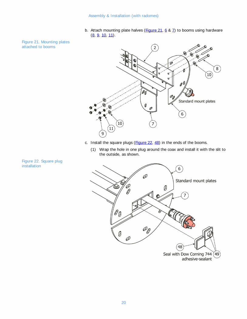
b. Attach mounting plate halves (Figure 21, 6 & 7) to booms using hardware (8, 9, 10, 11).
Figure 21. Mounting plates attached to booms
c. Install the square plugs (Figure 22, 48) in the ends of the booms.
(1) Wrap the hole in one plug around the coax and install it with the slit to the outside, as shown.
Figure 22. Square plug installation
20
Assembly & Installation (with radomes)
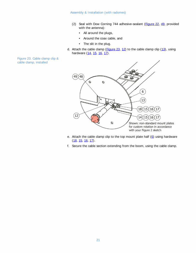
(2) Seal with Dow Corning 744 adhesive-sealant (Figure 22, 49, provided with the antenna):
• All around the plugs,
• Around the coax cable, and
• The slit in the plug.
d. Attach the cable clamp (Figure 23, 12) to the cable clamp clip (13), using hardware (14, 15, 16, 17).
Figure 23. Cable clamp clip & cable clamp, installed
e. Attach the cable clamp clip to the top mount plate half (6) using hardware (18, 15, 16, 17).
f. Secure the cable section extending from the boom, using the cable clamp.
21
Assembly & Installation (with radomes)
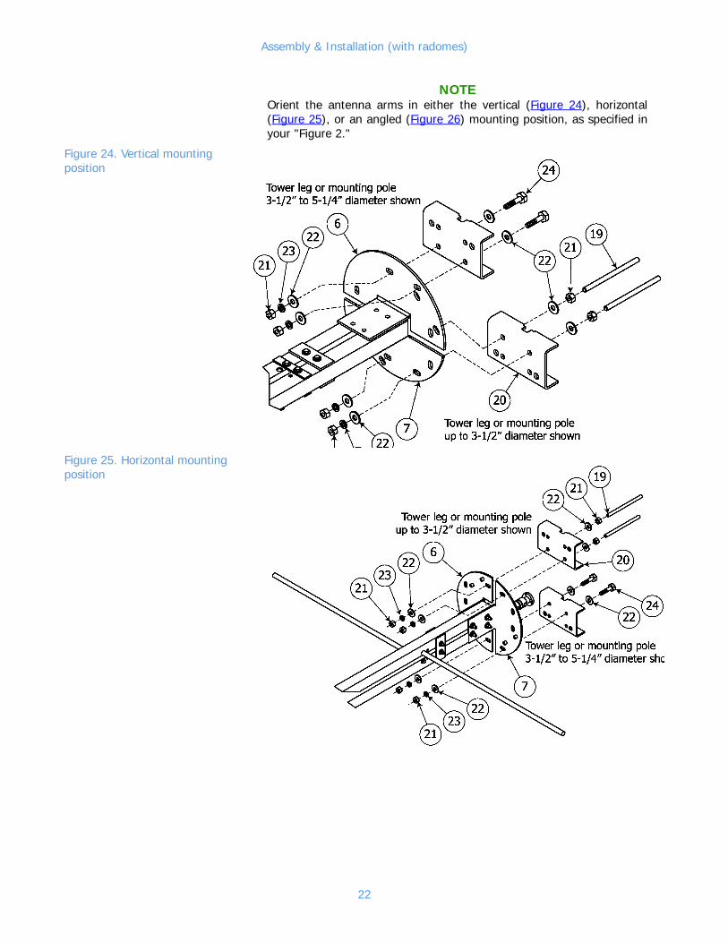
NOTEOrient the antenna arms in either the vertical (Figure 24), horizontal (Figure 25), or an angled (Figure 26) mounting position, as specified in your "Figure 2."
Figure 24. Vertical mounting position
Figure 25. Horizontal mounting position
22
Assembly & Installation (with radomes)
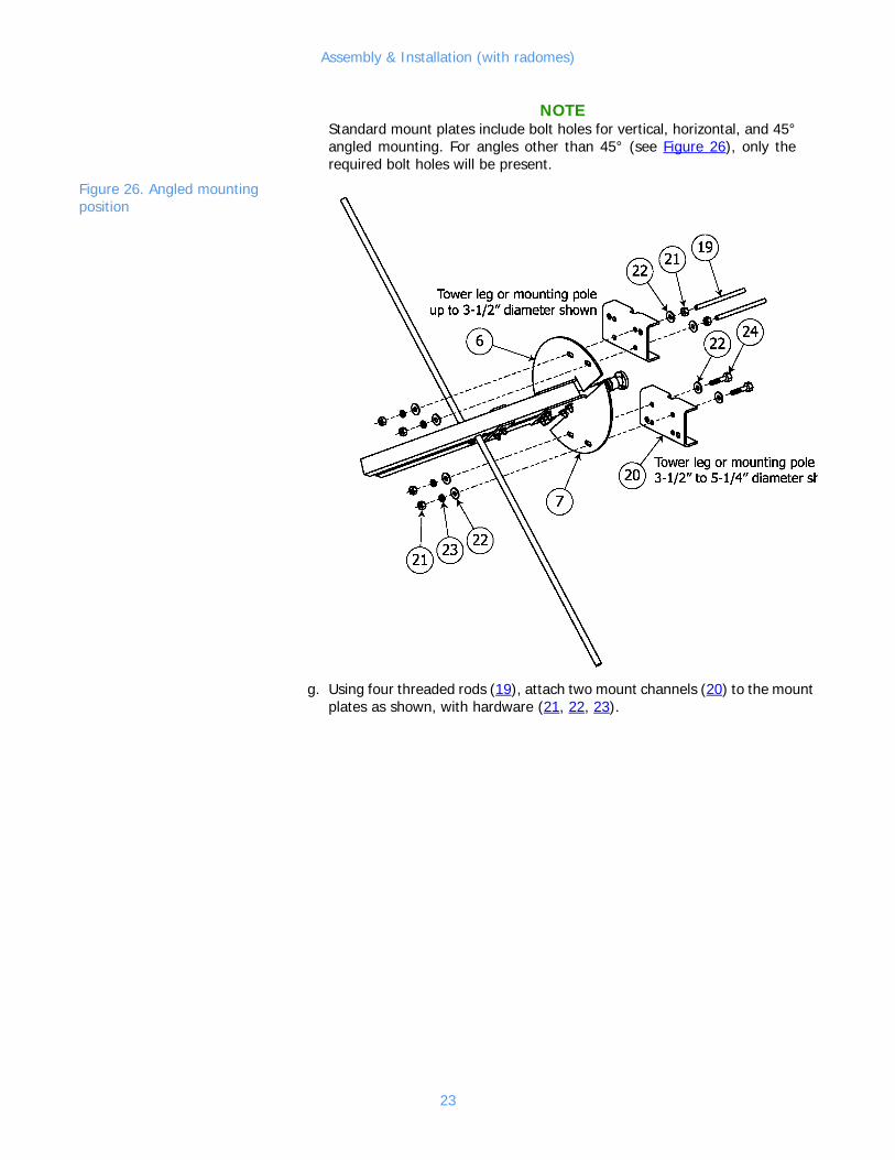
NOTEStandard mount plates include bolt holes for vertical, horizontal, and 45° angled mounting. For angles other than 45° (see Figure 26), only the required bolt holes will be present.
Figure 26. Angled mounting position
g. Using four threaded rods (19), attach two mount channels (20) to the mount plates as shown, with hardware (21, 22, 23).
23
Assembly & Installation (with radomes)
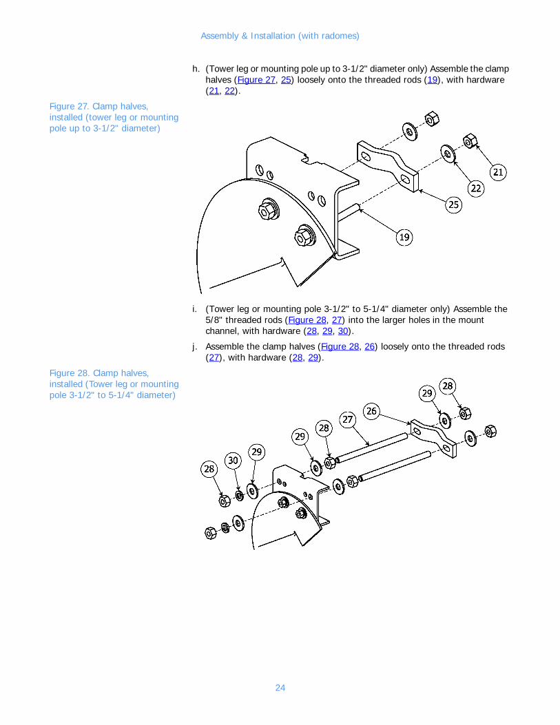
h. (Tower leg or mounting pole up to 3-1/2" diameter only) Assemble the clamp halves (Figure 27, 25) loosely onto the threaded rods (19), with hardware (21, 22).
Figure 27. Clamp halves, installed (tower leg or mounting pole up to 3-1/2" diameter)
i. (Tower leg or mounting pole 3-1/2" to 5-1/4" diameter only) Assemble the 5/8" threaded rods (Figure 28, 27) into the larger holes in the mount channel, with hardware (28, 29, 30).
j. Assemble the clamp halves (Figure 28, 26) loosely onto the threaded rods (27), with hardware (28, 29).
Figure 28. Clamp halves, installed (Tower leg or mounting pole 3-1/2" to 5-1/4" diameter)
24

Assembly & Installation (with radomes)
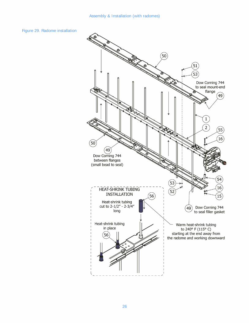
Install the radomes. a. Slip the radome halves (Figure 29, 50) over the antenna arms (1) onto the boom assembly (2).
b. Apply a line of Dow Corning 744 adhesive-sealant (49) between the flanges of the radome halves.
c. Using hardware (51, 52, 53), and starting at the center and working toward the ends, attach the radome flanges.
NOTEThe intent of the filler gasket is to prevent water getting into the antenna by entering between the booms. Install and seal accordingly.
d. Insert the silicone sponge filler gasket (54) between the antenna booms.
e. Insert the bolt (55) with washer (16) through the holes in the mount-end radome flanges and through the filler gasket, as shown. Secure the filler gasket with a second washer and nut (15).
f. Seal with adhesive-sealant:
• The mount-end radome flange, and
• Around the filler gasket.
CAUTIONTo ensure the heat-shrink tubing grips the radome boss, start warming the tubing at the base. When the base shrinks and grips the radome boss, move up away from the radome to the far end of the tubing.
g. Cut the heat-shrink tubing (56) into sections, each 2-1/2 to 2-3/4 inches (6.35 - 7 cm) long. Slip the heat-shrink tubing sections over the antenna arms and over the bosses on the radome. Using a heat gun, warm the heat-shrink tubing to seal the antenna arm ports in the radome.
h. Double-check to ensure all potential leak points are sealed with Dow Corning 744 adhesive-sealant (see Figure 30).
25
Assembly & Installation (with radomes)
Figure 29. Radome installation
26
Assembly & Installation (with radomes)
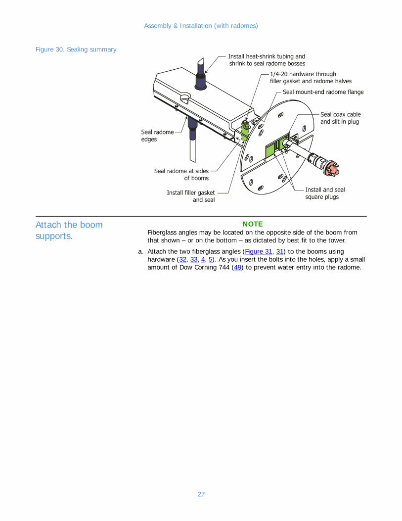
Figure 30. Sealing summary
Attach the boom supports.
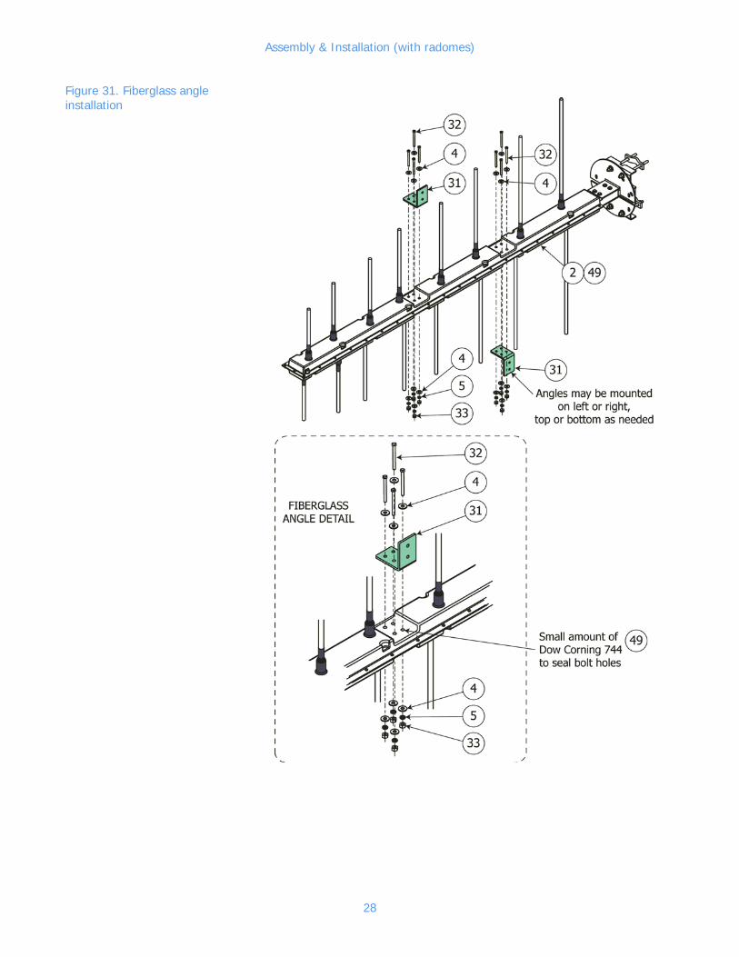
NOTEFiberglass angles may be located on the opposite side of the boom from that shown – or on the bottom – as dictated by best fit to the tower.
a. Attach the two fiberglass angles (Figure 31, 31) to the booms using hardware (32, 33, 4, 5). As you insert the bolts into the holes, apply a small amount of Dow Corning 744 (49) to prevent water entry into the radome.
27
Assembly & Installation (with radomes)
Figure 31. Fiberglass angle installation
28
Assembly & Installation (with radomes)
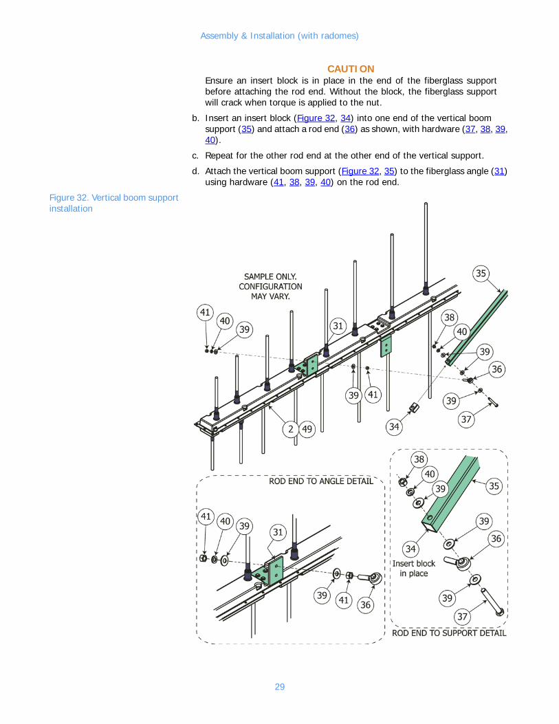
CAUTIONEnsure an insert block is in place in the end of the fiberglass support before attaching the rod end. Without the block, the fiberglass support will crack when torque is applied to the nut.
b. Insert an insert block (Figure 32, 34) into one end of the vertical boom support (35) and attach a rod end (36) as shown, with hardware (37, 38, 39, 40).
c. Repeat for the other rod end at the other end of the vertical support.
d. Attach the vertical boom support (Figure 32, 35) to the fiberglass angle (31) using hardware (41, 38, 39, 40) on the rod end.
Figure 32. Vertical boom support installation
29
Assembly & Installation (with radomes)
NOTEThe vertical boom support may be located on the opposite side of the boom from that shown – or on the bottom, angled down – as dictated by best fit to the tower.
e. Repeat step b to attach one end of the horizontal boom support (Figure 33, 42) to the other fiberglass angle using an insert block (34), a rod end (36), and hardware (37, 38, 39, 40, 41).
NOTEThe horizontal boom support may be located on the opposite side of the boom from that shown, as dictated by best fit to the tower.
Figure 33. Horizontal boom support, installed
NOTEThe second end of the horizontal support is left unfinished. It will be assembled at the time the antenna is mounted.
30
Assembly & Installation (with radomes)
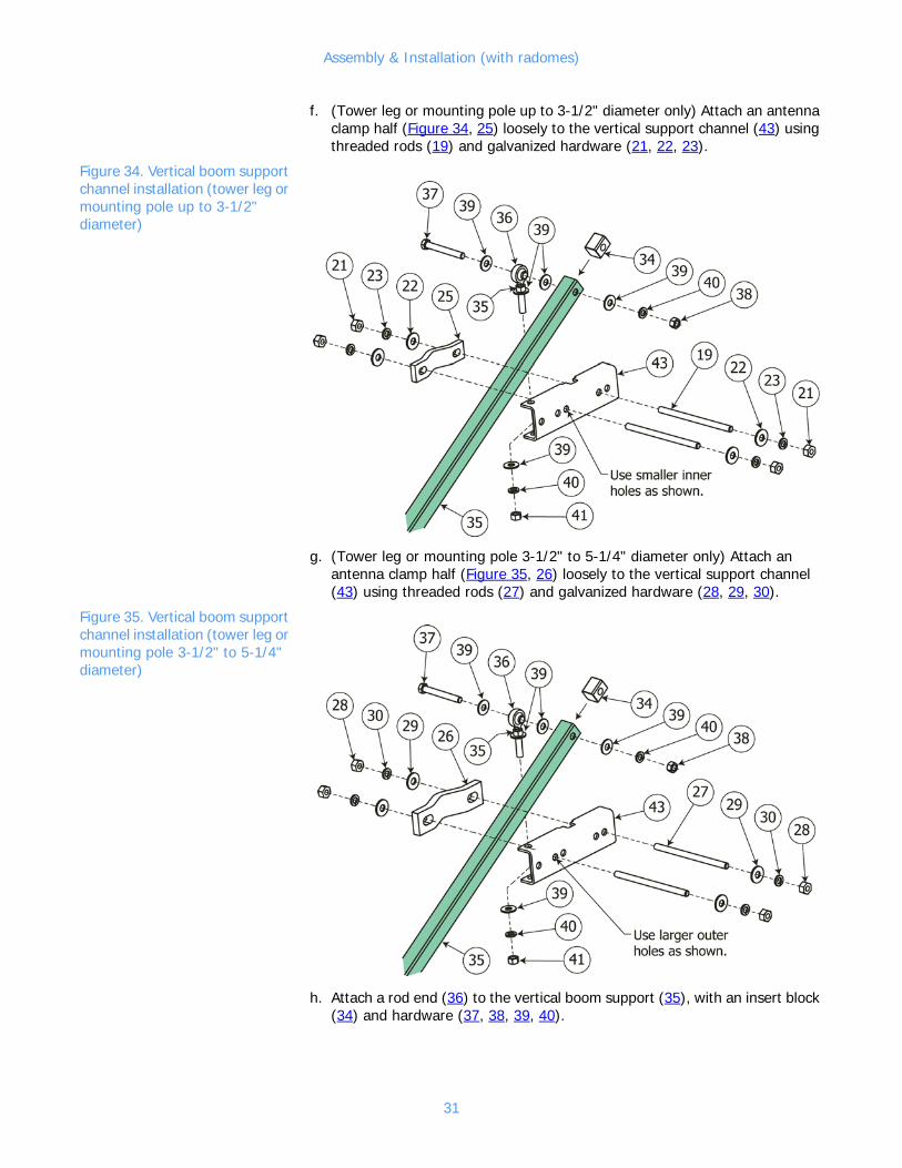
f. (Tower leg or mounting pole up to 3-1/2" diameter only) Attach an antenna clamp half (Figure 34, 25) loosely to the vertical support channel (43) using threaded rods (19) and galvanized hardware (21, 22, 23).
Figure 34. Vertical boom support channel installation (tower leg or mounting pole up to 3-1/2" diameter)
g. (Tower leg or mounting pole 3-1/2" to 5-1/4" diameter only) Attach an antenna clamp half (Figure 35, 26) loosely to the vertical support channel (43) using threaded rods (27) and galvanized hardware (28, 29, 30).
Figure 35. Vertical boom support channel installation (tower leg or mounting pole 3-1/2" to 5-1/4" diameter)
h. Attach a rod end (36) to the vertical boom support (35), with an insert block (34) and hardware (37, 38, 39, 40).
31
Assembly & Installation (with radomes)
i. Attach the rod end to the vertical support channel at the outer end of the vertical boom support using hardware (41, 39, 40).
NOTEDo not attach the support channel to the horizontal boom support (42) at this time.
Mount the antenna bay on the pole or tower.
CAUTION If you don’t get good electrical contact between the antenna and the mounting structure, the antenna may generate unwanted electrical sig-nals, and performance may be degraded.
a. Before mounting the antenna, scrape away any paint on the tower legs or mounting pole to ensure good electrical contact.
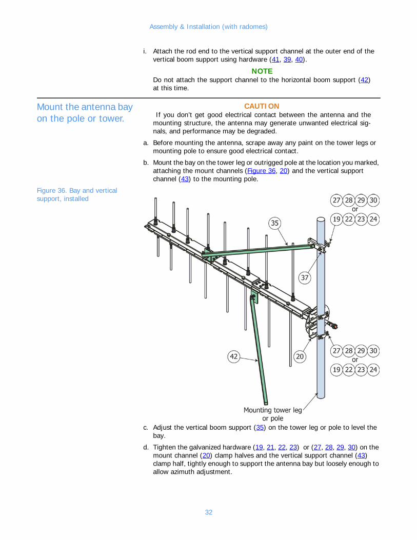
b. Mount the bay on the tower leg or outrigged pole at the location you marked, attaching the mount channels (Figure 36, 20) and the vertical support channel (43) to the mounting pole.
Figure 36. Bay and vertical support, installed
c. Adjust the vertical boom support (35) on the tower leg or pole to level the bay.
d. Tighten the galvanized hardware (19, 21, 22, 23) or (27, 28, 29, 30) on the mount channel (20) clamp halves and the vertical support channel (43) clamp half, tightly enough to support the antenna bay but loosely enough to allow azimuth adjustment.
32

Assembly & Installation (with radomes)
e. Attach a rod end (36) to the horizontal support channel (Figure 37, 43), with hardware (39, 40, 41).
f. Attach the horizontal support channel to a tower leg or pole that will be used for lateral bracing.
Figure 37. Horizontal support channel, installed
g. Adjust the bay to the proper azimuth.
h. Align the horizontal boom support (Figure 38, 42) with the rod end of the support channel, and measure the required length for the horizontal support.
Figure 38. Cut and attach the horizontal support.
33

Assembly & Installation (with radomes)
i. (If necessary) Cut the horizontal support to length.
j. Drill the end of the horizontal support, using the insert block (34) as a drill template.
k. With the insert block in place, connect the horizontal support to the rod end (36) using hardware (37, 38, 39, 40).
l. Tighten all hardware before proceeding.
m. Retouch the paint you removed in step a.
Drill drain holes in radome
a. Drill three drain holes in the radome. Drill at the lowest points of the radome as shown in Figure 39.
Figure 39. Drain hole locations
• “A” if vertical-mounted (see Figure 24), angled slightly upward
• “B” if vertical-mounted, angled exactly level or slightly downward
• “C” if horizontal-mounted (see Figure 25), angled slightly upward
• “D” if horizontal-mounted, angled exactly level or slightly downward
• “E” if angled-mounted (see Figure 26), angled slightly upward
• “F” if angled-mounted, angled exactly level or slightly downward
Repeat for additional bays.
Repeat installation for additional antenna bays if your system has more than one, arrayed vertically.
NOTEIf your system has multiple bays, arrayed vertically, go next to Power Divider Installation on page 37. If your system is a single antenna bay, continue with Connect the antenna to the transmitter. on page 35.
34
Assembly & Installation (with radomes)
Connect the antenna to the transmitter.
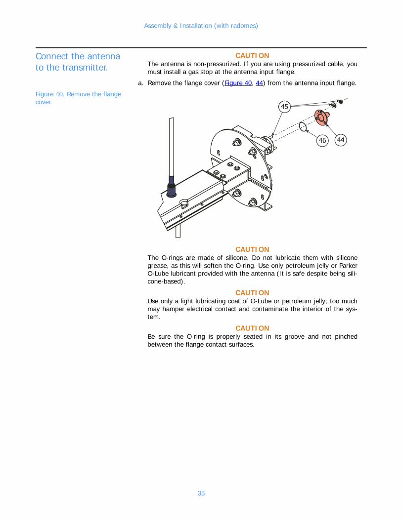
CAUTIONThe antenna is non-pressurized. If you are using pressurized cable, you must install a gas stop at the antenna input flange.
a. Remove the flange cover (Figure 40, 44) from the antenna input flange.
Figure 40. Remove the flange cover.
CAUTIONThe O-rings are made of silicone. Do not lubricate them with silicone grease, as this will soften the O-ring. Use only petroleum jelly or Parker O-Lube lubricant provided with the antenna (It is safe despite being sili-cone-based).
CAUTIONUse only a light lubricating coat of O-Lube or petroleum jelly; too much may hamper electrical contact and contaminate the interior of the sys-tem.
CAUTIONBe sure the O-ring is properly seated in its groove and not pinched between the flange contact surfaces.
35
Assembly & Installation (with radomes)
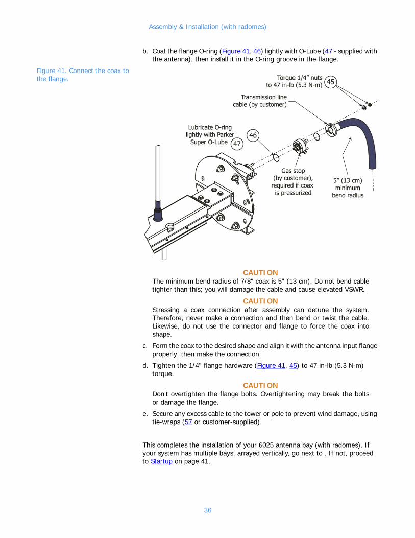
b. Coat the flange O-ring (Figure 41, 46) lightly with O-Lube (47 - supplied with the antenna), then install it in the O-ring groove in the flange.
Figure 41. Connect the coax to the flange.
CAUTIONThe minimum bend radius of 7/8" coax is 5" (13 cm). Do not bend cable tighter than this; you will damage the cable and cause elevated VSWR.
CAUTIONStressing a coax connection after assembly can detune the system. Therefore, never make a connection and then bend or twist the cable. Likewise, do not use the connector and flange to force the coax into shape.
c. Form the coax to the desired shape and align it with the antenna input flange properly, then make the connection.
d. Tighten the 1/4" flange hardware (Figure 41, 45) to 47 in-lb (5.3 N-m) torque.
CAUTIONDon't overtighten the flange bolts. Overtightening may break the bolts or damage the flange.
e. Secure any excess cable to the tower or pole to prevent wind damage, using tie-wraps (57 or customer-supplied).
This completes the installation of your 6025 antenna bay (with radomes). If your system has multiple bays, arrayed vertically, go next to . If not, proceed to Startup on page 41.
36

Power Divider Installation
4 Power Divider Installation
Mount the power divider.
CAUTIONThe antenna is non-pressurized. If you are using pressurized transmis-sion line cable, you must install a gas stop at the power divider input.
a. Before mounting the power divider, scrape away paint on the tower leg or mounting pole to ensure good electrical contact.
b. Mount the power divider (Figure 42, 58) to the mounting structure with its outlet ports roughly halfway between the top and botttom antenna bays.
Figure 42. Power divider installed and connected
37

Power Divider Installation
c. Retouch the paint removed in step a.
Connect the feedline cables.
a. Remove the flange covers (Figure 43, 44) from the antenna bay input flanges.
Figure 43. Remove the flange cover on each antenna bay.
CAUTIONThe O-rings are made of silicone. Do not lubricate them with silicone grease, as this will soften the O-ring. Use only petroleum jelly or Parker O-Lube lubricant provided with the antenna (It is safe despite being sili-cone-based).
CAUTIONUse only a light lubricating coat of O-Lube or petroleum jelly; too much may hamper electrical contact and contaminate the interior of the sys-tem.
CAUTIONBe sure the O-rings are properly seated in their grooves and not pinched between the flange contact surfaces.
b. Coat the flange O-rings (Figure 44, 46) lightly with petroleum jelly or O-Lube (supplied with the antenna), then install them in the O-ring grooves in the antenna input flanges.
CAUTIONThe minimum bend radius of 7/8" coax is 5" (13 cm). Do not bend cable tighter than this; you will damage the cable and cause elevated VSWR.
CAUTIONStressing a coax connection after assembly can detune the system. Therefore, never make a connection and then bend or twist the cable. Likewise, do not use the connector and flange to force the coax into shape.
c. Form the coax feedline sections (59) to the desired shape and align them with the antenna input flanges properly, then make the connections.
NOTEAntenna with radome shown. Without radome is similar..
38

Power Divider Installation
Figure 44. Connect the coax to the flange.
CAUTIONDon't overtighten the flange bolts. Overtightening may break the bolts or damage the flange.
d. Tighten the 1/4" flange hardware (45) to 47 lb-in (5.3 N-m) torque.
e. Connect the other end of the feedline cable to one of the power divider outputs. Torque to 20 lb-in (2.25 cm-kg).
f. Secure any excess cable to the tower or pole to prevent wind damage, using the tie-wraps (57) or customer-supplied cable clamps.
g. Repeat for the other bay(s).
Connect the transmission line to the power divider.
CAUTIONThe minimum bending radius for 1-5/8" coax is 10" (26 cm). Do not bend it too tightly; you may damage it.
a. Connect the transmission line cable from the transmitter to the power divider input, using a 1-5/8" flange hardware kit (Figure 42, 60), with a lightly lubricated O-ring (61).
b. Secure the transmission line cable to the mounting pole or tower leg, using customer-supplied cable clamps.
This completes the installation of your multi-bay 6025 antenna. Please pro-ceed to Startup on page 41.
NOTEAntenna with radome shown. Without radome is similar.
39

Startup
5 StartupWARNING
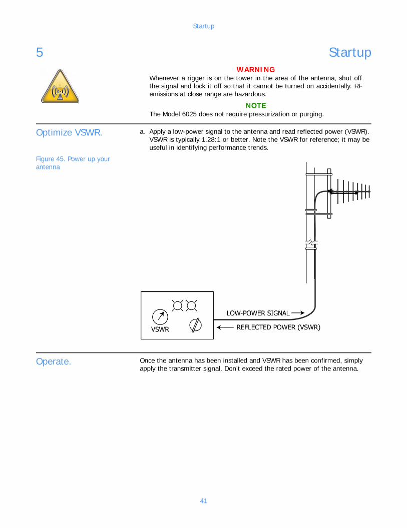
Whenever a rigger is on the tower in the area of the antenna, shut off the signal and lock it off so that it cannot be turned on accidentally. RF emissions at close range are hazardous.
NOTEThe Model 6025 does not require pressurization or purging.
Optimize VSWR. a. Apply a low-power signal to the antenna and read reflected power (VSWR). VSWR is typically 1.28:1 or better. Note the VSWR for reference; it may be useful in identifying performance trends.
Figure 45. Power up your antenna
Operate. Once the antenna has been installed and VSWR has been confirmed, simply apply the transmitter signal. Don’t exceed the rated power of the antenna.
41

Troubleshooting
6 Troubleshooting
Broad spectrum RF noise
This indicates that some component is not in good electrical contact with the tower. Make sure mounts are tight, that tower paint has been removed from under the mounts, and that components of other systems are likewise in good contact with the tower.
High VSWR This is caused by any factor that changes the impedance match between the antenna and the transmitter. Look for:
• Defective RF connector. Make sure connectors are in good shape, and that center pins are not bent over.
• Damage to any antenna components.
• Paint on radiators.
• Ice buildup on radiators.
• Interference from other tower components, especially components broken by wind or ice.
Change in coverage This may be caused by the same factors that can cause high VSWR. Look for VSWR changes as well.
Do recognize, however, that apparent changes in coverage may be due to sub-jective factors or faults of the receiving equipment. Before doing more than checking the VSWR, be sure that an actual coverage change has occurred.
43

Maintenance
7 MaintenanceWARNING
Whenever a rigger is on the tower in the area of the antenna, shut off the signal and lock it off so that it cannot be turned on accidentally. RF emissions at close range are hazardous.
Log We recommend that you keep a log of VSWR readings and any other perfor-mance notes and maintenance history for your antenna. Such a record can be invaluable for troubleshooting.
Inspection Whenever a rigger is on the tower for any reason, it is a good idea to have him check your antenna for general condition, looseness of connectors and mounts, and electrical damage.
Paint The radiator should never be painted; this will affect the VSWR.
Return Policy When returning any material to the factory, be sure to call your salesperson and obtain an returned materials authorization (RMA) number first. Material may be refused and sent back to you at your expense if you don’t do this.
45


Parts
8 Parts
Parts list NOTEItem callouts are consistent across all the illustrations throughout this manual.
Table 2. Parts list
Item & DescriptionQty w/o radomes, to 3-1/2" mount-ing pole
Qty withradomes, to 3-1/2" mount-ing pole
Qty w/o radomes, 3-1/2" - 5-1/4" mount pole
Qty withradomes, 3-1/2" - 5-1/4" mount pole
Appearance (not to scale)
1. Antenna arms, approxi-mately 34.7", 32.3", 28.7", 26.2", 23.9", 21.9", 19.3", and 17.4" longP/N 99186-various
2 each size
2 each size
2 each size
2 each size
2. Boom assemblyP/N 99181-G502
1 1 1 1
3. 5/16-18 x 3/4" hex head bolt, stainless steel
16 16 16 16
4. 5/16" flat washer, stainless steel
32 32 32 32
5. 5/16" lock washer, stainless steel
24 24 24 24
6. Top formed mounting plateP/N 99195-01 or equivalent
1 1 1 1
7. Bottom formed mounting plateP/N 99195-02 or equivalent
1 1 1 1
8. 3/8-16 x 3-1/4" hex head bolt, stainless steel
4 4 4 4
9. 3/8" hex nut, stainless steel 4 4 4 4
47
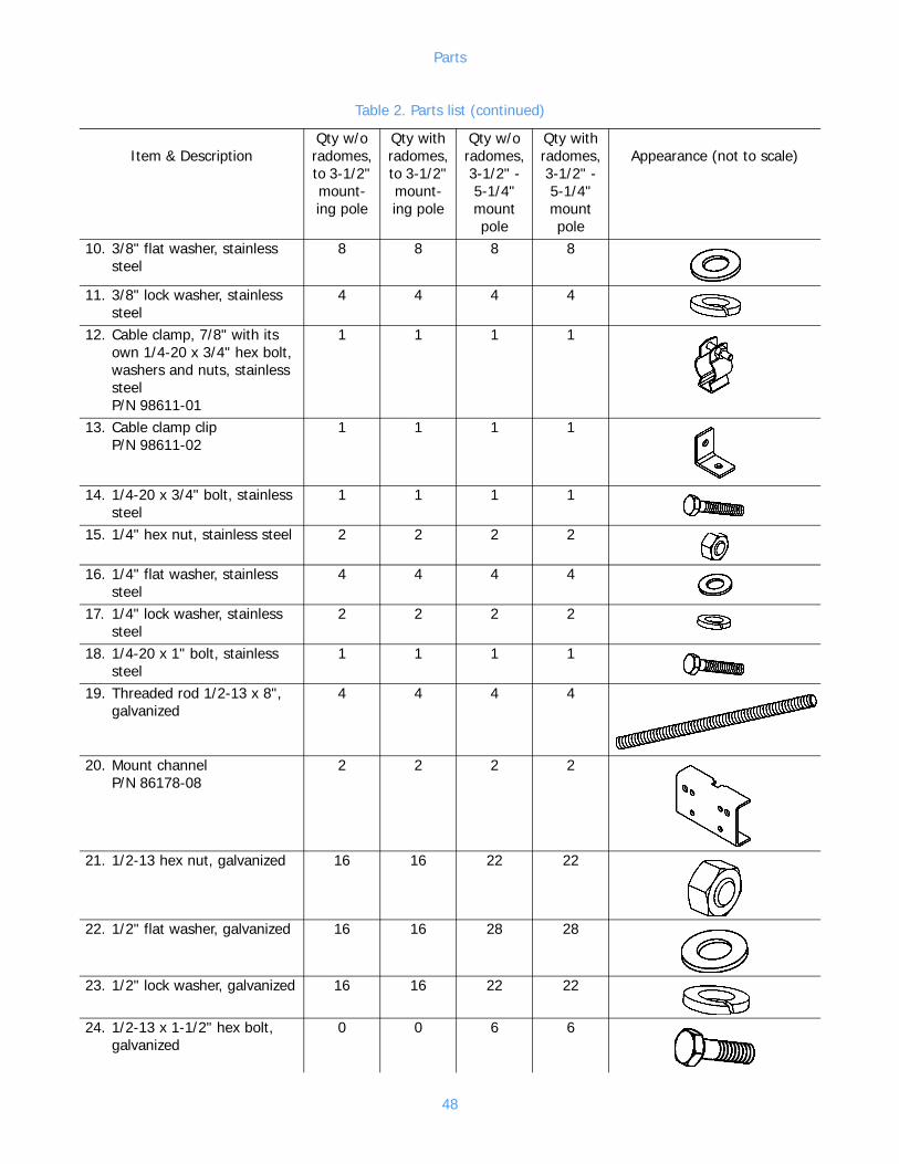
Parts
10. 3/8" flat washer, stainless steel
8 8 8 8
11. 3/8" lock washer, stainless steel
4 4 4 4
12. Cable clamp, 7/8" with its own 1/4-20 x 3/4" hex bolt, washers and nuts, stainless steelP/N 98611-01
1 1 1 1
13. Cable clamp clipP/N 98611-02
1 1 1 1
14. 1/4-20 x 3/4" bolt, stainless steel
1 1 1 1
15. 1/4" hex nut, stainless steel 2 2 2 2
16. 1/4" flat washer, stainless steel
4 4 4 4
17. 1/4" lock washer, stainless steel
2 2 2 2
18. 1/4-20 x 1" bolt, stainless steel
1 1 1 1
19. Threaded rod 1/2-13 x 8", galvanized
4 4 4 4
20. Mount channelP/N 86178-08
2 2 2 2
21. 1/2-13 hex nut, galvanized 16 16 22 22
22. 1/2" flat washer, galvanized 16 16 28 28
23. 1/2" lock washer, galvanized 16 16 22 22
24. 1/2-13 x 1-1/2" hex bolt, galvanized
0 0 6 6
Table 2. Parts list (continued)
Item & DescriptionQty w/o radomes, to 3-1/2" mount-ing pole
Qty withradomes, to 3-1/2" mount-ing pole
Qty w/o radomes, 3-1/2" - 5-1/4" mount pole
Qty withradomes, 3-1/2" - 5-1/4" mount pole
Appearance (not to scale)
48
Parts
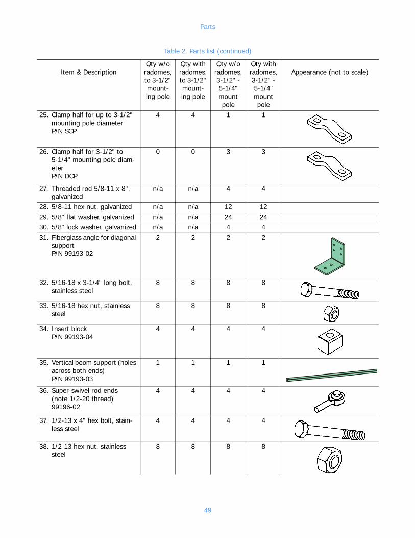
25. Clamp half for up to 3-1/2" mounting pole diameterP/N SCP
4 4 1 1
26. Clamp half for 3-1/2" to 5-1/4" mounting pole diam-eterP/N DCP
0 0 3 3
27. Threaded rod 5/8-11 x 8", galvanized
n/a n/a 4 4
28. 5/8-11 hex nut, galvanized n/a n/a 12 1229. 5/8" flat washer, galvanized n/a n/a 24 2430. 5/8" lock washer, galvanized n/a n/a 4 431. Fiberglass angle for diagonal
supportP/N 99193-02
2 2 2 2
32. 5/16-18 x 3-1/4" long bolt, stainless steel
8 8 8 8
33. 5/16-18 hex nut, stainless steel
8 8 8 8
34. Insert blockP/N 99193-04
4 4 4 4
35. Vertical boom support (holes across both ends)P/N 99193-03
1 1 1 1
36. Super-swivel rod ends(note 1/2-20 thread)99196-02
4 4 4 4
37. 1/2-13 x 4" hex bolt, stain-less steel
4 4 4 4
38. 1/2-13 hex nut, stainless steel
8 8 8 8
Table 2. Parts list (continued)
Item & DescriptionQty w/o radomes, to 3-1/2" mount-ing pole
Qty withradomes, to 3-1/2" mount-ing pole
Qty w/o radomes, 3-1/2" - 5-1/4" mount pole
Qty withradomes, 3-1/2" - 5-1/4" mount pole
Appearance (not to scale)
49
Parts
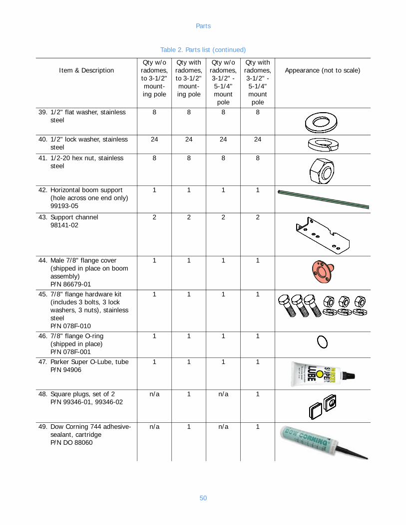
39. 1/2" flat washer, stainless steel
8 8 8 8
40. 1/2" lock washer, stainless steel
24 24 24 24
41. 1/2-20 hex nut, stainless steel
8 8 8 8
42. Horizontal boom support (hole across one end only)99193-05
1 1 1 1
43. Support channel98141-02
2 2 2 2
44. Male 7/8" flange cover(shipped in place on boom assembly)P/N 86679-01
1 1 1 1
45. 7/8" flange hardware kit (includes 3 bolts, 3 lock washers, 3 nuts), stainless steelP/N 078F-010
1 1 1 1
46. 7/8" flange O-ring (shipped in place)P/N 078F-001
1 1 1 1
47. Parker Super O-Lube, tubeP/N 94906
1 1 1 1
48. Square plugs, set of 2P/N 99346-01, 99346-02
n/a 1 n/a 1
49. Dow Corning 744 adhesive-sealant, cartridgeP/N DO 88060
n/a 1 n/a 1
Table 2. Parts list (continued)
Item & DescriptionQty w/o radomes, to 3-1/2" mount-ing pole
Qty withradomes, to 3-1/2" mount-ing pole
Qty w/o radomes, 3-1/2" - 5-1/4" mount pole
Qty withradomes, 3-1/2" - 5-1/4" mount pole
Appearance (not to scale)
50

Parts
50. Radome halfP/N 99475-01
n/a 2 n/a 2
51. 10-32 hex washer head screw, stainless steel
n/a 35 n/a 35
52. 10-32 Nylok hex nut, stain-less steel
n/a 41 n/a 41
53. #10 flat washer, stainless steel
n/a 49 n/a 49
54. Silicone sponge filler gasketP/N 99348-03
n/a 1 n/a 1
55. 1/4-20 x 2-3/4" hex bolt n/a 1 n/a 1
56. Heat-shrink tubing, 1" IDP/N 57941-01
n/a 48 in n/a 48 in
57. Tie-wrapP/N TY529MX
10 10 10 10
58. Power divider assembly (includes mounts and hard-ware)P/N: Various
1 if multiple bays;0 if single-bay
59. Coax feedline sectionP/N: Various
1 per antenna bay, if multiple bays;0 if single bay
Table 2. Parts list (continued)
Item & DescriptionQty w/o radomes, to 3-1/2" mount-ing pole
Qty withradomes, to 3-1/2" mount-ing pole
Qty w/o radomes, 3-1/2" - 5-1/4" mount pole
Qty withradomes, 3-1/2" - 5-1/4" mount pole
Appearance (not to scale)
51

60. 1-5/8" flange hardware kit (includes 4 bolts, 4 lock washers, 4 nuts), stainless steelP/N 158F-010
1 if multiple bays;0 if single-bay
(shipped in place on power divider input)
61. 1-5/8" flange O-ringP/N 158F-001
1 if multiple bays;0 if single-bay
(shipped in place on power divider input)
Table 2. Parts list (continued)
Item & DescriptionQty w/o radomes, to 3-1/2" mount-ing pole
Qty withradomes, to 3-1/2" mount-ing pole
Qty w/o radomes, 3-1/2" - 5-1/4" mount pole
Qty withradomes, 3-1/2" - 5-1/4" mount pole
Appearance (not to scale)
Related Documents