LOG-IDEAH: ASP for Architectonic Asset Preservation Viviana Novelli 1 , Marina De Vos 2 , Julian Padget 2 , and Dina D’Ayala 1 1 Department of Architecture and Civil Engineering University of Bath, BA2 7AY Bath, UK E-mail: {v.i.novelli,d.f.d’ayala}@bath.ac.uk 2 Department of Computer Science University of Bath, BA2 7AY Bath, UK E-mail: {mdv,jap}@cs.bath.ac.uk Abstract To preserve our cultural heritage, it is important to preserve our architectonic assets, comprising buildings, their decorations and the spaces they encompass. In some geographical areas, occa- sional natural disasters, specifically earthquakes, damage these cultural assets. Perpetuate is a European Union funded project aimed at establishing a methodology for the classification of the damage to these buildings, expressed as “collapse mechanisms”. Structural engineering research has identified 17 different collapse mechanisms for masonry buildings damaged by earthquakes. Following established structural engineering practice, paper-based decisions trees have been spe- cified to encode the recognition process for each of the various collapse mechanisms. In this paper, we report on how answer set programming has been applied to the construction of a machine- processable representation of these collapse mechanisms as an alternative for these decision-trees and their subsequent verification and application to building records from L’Aquila, Algiers and Rhodes. As a result, we advocate that structural engineers do not require the time-consuming and error-prone method of decisions trees, but can instead specify the properties of collapse mechanisms directly as an answer set program. 1998 ACM Subject Classification D.1.6 Logic Programming Keywords and phrases Answer set programming, structural engineering, knowledge representa- tion Digital Object Identifier 10.4230/LIPIcs.ICLP.2012.393 1 Introduction It is useful to be able to make a rapid and reliable assessment of the vulnerability of a building after a seismic shock, to determine (i) the stability of the building and hence the acceptable proximity of public access (ii) what immediate preservation actions are appropriate, and (iii) potential risks from subsequent seismic activity. The Perpetuate project aims to combine two approaches in order to deliver assessments with a higher degree of confidence. The one on which we report here takes the form of an expert survey, based on an approach called LOG-IDEAH (LOGic trees for the Identifica- tion of Damage due to Earthquakes for Architectural Heritage) [10]. The complementary mechanical model-based approach is called FaMIVE (Failure Mechanism Identification and Vulnerability Evaluation) [2, 3, 4]. Both procedures are aimed at identifying the seismic © Viviana Novelli, Marina De Vos, Julian Padget, and Dina D’Ayala; licensed under Creative Commons License ND Technical Communications of the 28th International Conference on Logic Programming (ICLP’12). Editors: A. Dovier and V. Santos Costa; pp. 393–403 Leibniz International Proceedings in Informatics Schloss Dagstuhl – Leibniz-Zentrum für Informatik, Dagstuhl Publishing, Germany

Welcome message from author
This document is posted to help you gain knowledge. Please leave a comment to let me know what you think about it! Share it to your friends and learn new things together.
Transcript

LOG-IDEAH: ASP for Architectonic AssetPreservationViviana Novelli1, Marina De Vos2, Julian Padget2, andDina D’Ayala1
1 Department of Architecture and Civil EngineeringUniversity of Bath, BA2 7AYBath, UKE-mail: {v.i.novelli,d.f.d’ayala}@bath.ac.uk
2 Department of Computer ScienceUniversity of Bath, BA2 7AYBath, UKE-mail: {mdv,jap}@cs.bath.ac.uk
AbstractTo preserve our cultural heritage, it is important to preserve our architectonic assets, comprisingbuildings, their decorations and the spaces they encompass. In some geographical areas, occa-sional natural disasters, specifically earthquakes, damage these cultural assets. Perpetuate is aEuropean Union funded project aimed at establishing a methodology for the classification of thedamage to these buildings, expressed as “collapse mechanisms”. Structural engineering researchhas identified 17 different collapse mechanisms for masonry buildings damaged by earthquakes.Following established structural engineering practice, paper-based decisions trees have been spe-cified to encode the recognition process for each of the various collapse mechanisms. In this paper,we report on how answer set programming has been applied to the construction of a machine-processable representation of these collapse mechanisms as an alternative for these decision-treesand their subsequent verification and application to building records from L’Aquila, Algiers andRhodes. As a result, we advocate that structural engineers do not require the time-consumingand error-prone method of decisions trees, but can instead specify the properties of collapsemechanisms directly as an answer set program.
1998 ACM Subject Classification D.1.6 Logic Programming
Keywords and phrases Answer set programming, structural engineering, knowledge representa-tion
Digital Object Identifier 10.4230/LIPIcs.ICLP.2012.393
1 Introduction
It is useful to be able to make a rapid and reliable assessment of the vulnerability of a buildingafter a seismic shock, to determine (i) the stability of the building and hence the acceptableproximity of public access (ii) what immediate preservation actions are appropriate, and(iii) potential risks from subsequent seismic activity.
The Perpetuate project aims to combine two approaches in order to deliver assessmentswith a higher degree of confidence. The one on which we report here takes the form of anexpert survey, based on an approach called LOG-IDEAH (LOGic trees for the Identifica-tion of Damage due to Earthquakes for Architectural Heritage) [10]. The complementarymechanical model-based approach is called FaMIVE (Failure Mechanism Identification andVulnerability Evaluation) [2, 3, 4]. Both procedures are aimed at identifying the seismic
© Viviana Novelli, Marina De Vos, Julian Padget, and Dina D’Ayala;licensed under Creative Commons License ND
Technical Communications of the 28th International Conference on Logic Programming (ICLP’12).Editors: A. Dovier and V. Santos Costa; pp. 393–403
Leibniz International Proceedings in InformaticsSchloss Dagstuhl – Leibniz-Zentrum für Informatik, Dagstuhl Publishing, Germany

394 LOG-IDEAH: ASP for Architectonic Asset Preservation
behaviour of an architectonic asset on the basis of data collected by rapid survey or by pho-tographic observation. The difference between the two methodologies is that LOG-IDEAHis an intuitive (human) logic procedure that relies on seismic damage collection for theidentification of the failure modes of the architectonic assets, while FaMIVE is a numericalapproach which uses geometric and mechanical (based on the properties of the buildingmaterials involved) data for the calculation of the performance of historical buildings.
The remainder of the paper is structured as follows: (i) we next (section 2) providethe context for the application, introduce the necessary domain terminology used in therest of the paper and explain the hierarchical approach to the identification of individualbuilding elements that forms the basis for the constructive procedure for the recognitionof collapse mechanisms (ii) we then set out (section 3) how this damage and asset data isused to determine the possible collapse mechanisms; we start from the traditional structuralengineering method of decision trees; this is followed by a much easier, declarative and com-putational approach of representing the building data and requirements for the individualcollapse mechanisms as an answer set program (iii) in section 4 we briefly describe the datacapture mechanism used to acquire the data to be used by the analysis, and (iv) in section 5review the process and outline plans for future development.
2 Architectonic Asset Analysis
LOG-IDEAH depends upon an hierarchical approach, in which the architectonic asset isdeconstructed into façades, the façades into structural elements and the structural elementsinto artistic assets. On the basis of this hierarchical approach, a logical methodology for theacquisition of the data has been developed in order to collect seismic damage data on siteor by photographic observation.
Data collection for LOG-IDEAH entails the recording of information related to the dam-age position, damage type and damage level, that are observed at the level of the structuralelements and artistic assets of the architectonic asset under inspection.
The collected data is then interpreted by means of logic trees that represent the know-ledge and expertise of structural engineers, as they would use it for the identification ofthe global behaviour of an architectonic asset, and to recognise the failure modes of thearchitectonic asset in question.
2.1 Ontology
As with all disciplines, a comprehensive ontology1 has been developed to capture and pre-cisely define domain concepts and their relationships. Because the description of the analysisprocess is necessarily expressed in terms of this ontology, we give a brief overview of theelements required for reading the remainder of this paper. A formal representation in OWLhas been developed, but that is not the subject of this paper and is not used directly inwhat follows. There are four top-level concept classes:Architectonic asset (AA): This covers seven classes of buildings (A, ..., G) from man-
sions, through mosques, aqueducts, city walls and obelisks to historical centres (suchas L’Aquila, in which the case-study building treated here is located).
1 While using the word ontology we are not referring to semantic annotation in terms of an XMLdescription, but an establied set of related concepts in the field of structural engineering

V.I. Novelli, M. De Vos, J.A. Padget, and D. D’Ayala 395
Macro-element (ME): This is a set of abstract concepts, used to group structural elements,comprising four classes: vertical, horizontal, vaulted and staircases.
Structural element (SE): This comprises four groups, corresponding to the MEs above, ofconcrete classes such as piers and spandrels (vertical), rafters and tie-beams (horizontal),buttresses and bosses (vaulted) and cantilever and steps (staircases).
Artistic asset (AA): This is a set of three groups of three abstract classes, used to categorizethe various forms of decoration that may be attached to a structural element. Fresco’s,friezes are just two examples of artistic assests.
2.2 Localisation and Identification of DamageThe essence of the the survey approach is to construct a rectilinear map of each façade,based on the structural elements (SE) of which it is composed, label each SE by type (pier,pillar, spandrel, arch) and associate with it the kind of damage (vertical crack, horizontalcrack, diagonal crack) and the degree of damage (light, severe, near collapse, collapsed).This data then forms the input to the encoding of the structural engineer’s decision treethat identifies the collapse mechanism.
The zone under consideration (and the buildings within it) may be thought of as a n-arytree, rooted at the zone identifier, with whichever district the building is located, whoseleaves are, in the extreme, the artistic assets, such as a carving or a balcony, that decoratethe building and the interior nodes are everything in between.
The ultimate objective, from an engineering perspective, is to establish a relationshipbetween each artistic asset and the façade to which it is attached, since this is how it maybe damaged if the façade is subject to a collapse mechanism. This is achieved by defininga hierarchical naming scheme. The method starts by dividing the urban map into blocksand enumerating the blocks and the buildings located therein. Thus, the name associatedwith a particular asset is given by (block number + building number), followed by thefaçade orientation. The final suffix is the number of the region (in a rectilinear map) of thefaçade plus a letter that refers to the type of topological relationship between the asset andthe façade. For example (see Figure 1), in the map of the historical centre of L’Aquila –damaged by an earthquake in 2009 – the building highlighted in red is named 10.4, since thisbuilding is the fourth building of the block number 10. Furthermore, a sequence of façadesis associated with this building, describing those which have been inspected, namely 10.4swand 10.4nw, while those on the remaining sides are still to be inspected.
The relationship between façades and the structural elements is established after identi-fying vertical (piers/pillars/columns) and horizontal (spandrels/arches) structural elementsof the façade, as shown in Figure 1. Each structural element is labelled by a pair of pos-itive integers, where the first is the number of the floor, encoding the horizontal alignmentof the elements and the second is the position of the element, encoding the vertical align-ment. Thus, looking at Building 10.4 (Figure 1d) and façade 10.4sw, the identification ofits structural elements is clear.
Once these relationships have been established, seismic damage information at the levelof SEs is collected, then interpreted, first at the level of MEs (for example, façade) and thenat the level of AA (building).
The damage type classification is given by: (i) H, denoting a horizontal crack (ii) V, avertical crack (iii) D1, a diagonal crack from upper right to bottom left (iv) D2, a diagonalcrack from upper left to bottom right (v) X, being the occurrence of D1 and D2 in the samestructural element (vi) Sp, denoting spalling, which indicates surface fragmentation of the(building) material, and (vii) Cr, denoting crushing, which indicates interior fragmentation.
ICLP’12

396 LOG-IDEAH: ASP for Architectonic Asset Preservation
10
2244
7
9
5
22
13
14
1517
18
1929
10
2244
7
9
5
22
13
14
1517
18
1929
(a) The division of L’Aquila into districts
(b) Identification of the façades onindividual buildigs in district 10
Horizontal Elements
Vertical Elements
Horizontal Elements
Vertical Elements
(c) The structural enumeration convention
10.4sw10.4sw
(d) Facade sw of building 10.4 isbroken into structural elements to en-able reference to pier 2 on floor 1
Figure 1 The division of L’Aquila into districts, façade identification on individual buildings indistrict 10, the structural enumeration convention and the referencing of pier 2 on floor 1.
The damage level severity classification is given by: (i) LD: light damage (ii) SD: severedamage (iii) NC: near collapse, and (iv) C: collapsed.
All of the above is carried over directly into the ASP encoding (see Figure 4).
3 Representation and Reasoning
3.1 Decision Trees
One of the primary deliverables of the Perpetuate project is a process for determining thevarious collapse mechanisms for earthquake-damaged masonry buildings, by examining thedamage to the structural elements and the artistic assets of the building. So far, the archi-tects have identified 19 distinct such mechanisms, each of which is depicted in Figure 2.
The original (manual) method developed for identifying the collapse mechanism uses thetraditional structural engineering approach of decision trees. Figure 3 shows the decisiontree for collapse mechanism A. This mechanism occurs when there are vertical cracks oneither side of a façade starting from the top floor. The graphics on the right highlight onwhich floor the decision tree is operating at a given time.
Such a manual approach, which also requires specialized knowledge on the part of theobserver, is not very efficient at scale for dealing with an earthquake zone where severalhundreds of buildings are damaged, like for example the sites involved in the PerpetuateProject: L’Aquila and the Casbah of Algiers. This led to the requirement for a compu-tational mechanism to support the survey process by non-experts. Given the intrinsicallyprocedural nature of decision trees, a procedural programming approach could have beenchosen. However, given the declarative description of the collapse mechanisms (e.g. vertical

V.I. Novelli, M. De Vos, J.A. Padget, and D. D’Ayala 397
A A2 (vertical Cracks) B2 (diagonal cracks)
B1-Left B1-Right
C-Left C-Right (left or right corner of the facade)
D-Left or D-Right (left or right corner of the facade)
E1 (piers-pillars) E2 (spandrels-arches)
F
G H1 (piers-pillars) H2
(spandrels-arches) M1 M2
Figure 2 Illustration of the variety of collapse mechanisms.
cracks on either side of a façade) provided by the architects on the project, we believedthe declarative paradigm would be more suitable. In addition to providing a computa-tional model, it also allowed us to verify and validate the decision trees provided by thearhcitects. We have chosen to implement the collapse mechanism inference procedure andthe description of the buildings using answer set programming[8, 9] with AnsProlog as theimplementation language[1].
3.2 Answer Set ProgrammingAnswer-set programming (ASP) [8] is a declarative programming paradigm in which a logicprogram is used to describe the requirements that must be fulfilled by the solutions of acertain problem. The solutions of the problem can be obtained through the interpretationof the answer sets of the program, usually defined through a variant or extension of thestable-model semantics [8].
In this paper we use AnsProlog as our implementation language. Its basis componentare atoms, elements that can be either true or false. An atom a can be negated usingnegation as failure. A literal is an atom a or a negated atom not a. We say that not a is trueif we cannot find evidence supporting the truth of a. Using atoms and literals as buildingblocks we can create rules. In their general form they are represented as:
a : −b1, . . . , bm, not c1, . . . , not cn.
where a, bi, and cj are atoms. Intuitively, this can be read as: if all atoms bi are known/trueand no atom ci is known/true, then a must be known/true.
ICLP’12

398 LOG-IDEAH: ASP for Architectonic Asset Preservation
nf=nfloor
(nf.1) e PierCrackLocation(k)
and
(nf.a(nf)) e PierCrackLocation(k)
Yes
PierCrackLocation(k)(Index1).crack
is V
Yes
nf=nf-1
nf=0
Mechanism A of VeME(K)from nfloor to nf
Yes
No
nf=nf+1
Ago to A-r
Logic tree: A
Index1=Index of (nf.1) in PierCrackLocation(k)
Index2=Index of (nf.a(nf)) in PierCrackLocatio(k)
PierCrackLocation(k)(Index1).crack=
PierCrackLocation((k)(Index2).crackNo
No
(nf.1) e PierCrackLocation(k)
and
(nf.a(nf)) e PierCrackLocation(k)
Yes
PierCrackLocation(k)(Index1).crack
is V
Index1=Index of (nf.1) in PierCrackLocation(k)
Index2=Index of (nf.a(nf)) in PierCrackLocation(k)
PierCrackLocation(k)(Index1).crack=
PierCrackLocation((k)(Index2).crack
go to F
Yes
No
Yes
No
No
No
Yes
go to A-r
go to A-r
Figure 3 The logic tree for mechanism A (left) and sketches (right).
We refer to a as the head and b1, . . . , bm, not c1, . . . , not cn as the body of the rule. Ruleswith empty bodies are called facts. Rules with empty heads are referred to as constraints,indicating that no solution should be able to satisfy the body. A program is a set of rules.The semantics is defined in terms of answer sets, i.e. assignments of true and false to allatoms in the program that satisfy the rules in a minimal and consistent fashion, taking intoaccount that the truth of an atom cannot be based on the absence of proof (i.e. the truthof an atom cannot indirectly be inferred by its own negation). A program has zero or moreanswer sets, each corresponding to a solution.
Algorithms and implementations for obtaining answer sets of logic programs are referredto as answer-set solvers. The most popular and widely used solvers are DLV [6], providingsolver capabilities for disjunctive programs, and the SAT inspired clasp [7].

V.I. Novelli, M. De Vos, J.A. Padget, and D. D’Ayala 399
% @block buildingconstants {% provides the constants used in damage description of buildings% @atom damageType(T)% type of damage from vertical;horizontal;diagonal crack / ;% diagonal crack \ ;% x shape;spalling;crushing% @atom damageLevel(L)% severity of damage from damage limitation;significant damage;% near collapse;collapse
damageType(v;h;d1;d2;x;s;cr).damageLevel(ld;sd;nc;c).
Figure 4 The facts describing the damage types and levels of buildings.
3.3 AnsProlog for Collapse Mechanisms
Instead of using the procedural decision-trees as our starting point, we used the sketches ofthe collapse mechanisms together with a discussion with a domain expert as our startingpoint. Since the answer set program will be integrated with web-interface (see next section)that collects data for each building individually, our answer set program only needs toconsider the representation of a single building at any given time.
To start the modelling process, it was necessary to decide upon the representation ofthe various structural elements of the building. With the objective of making the logicaccessible to the architects, we annotated all our program fragments with a description ofthe atoms used. To do so, we used a subset of the annotation language lana[5]. Thislanguage uses program comments plus semantic tags in the style of Javadoc t o describe thevarious components of the program. We only used the @block tag, indicating a collectionof rules, and the @atom tag to describe individual atoms and their terms.
We first defined facts to denote the various damage types and damage levels. Theencoding is shown in Figure 4.
This was followed with facts for the description of the structural elements themselves.The ultimate goal is that this information is automatically generated on the basis of in-formation gathered by non-expert surveyors on site (see next section for more informationon the data collection). For some of the collapse mechanisms, numerical information is re-quired, such as the number of piers with a vertical crack or the percentage of piers that aredamaged. Since this data can be generated during the data collection process, we choose toincorporate it as facts rather than compute it in the answer set program.
Figure 5 contains the description of a synthetic building with one visible façade whichexhibits an out-of-plane collapse mechanism of type A.
Having the description of the building, the different collapse mechanisms can be encoded.Rather than using the rather procedural decision trees as a starting point, the encoding isderived solely from the schematic pictures (see right-hand side of Figure 5 for an example).Each collapse mechanism is encoded in a separate file and LANA block for ease of testing,flexibility and readability.
In this paper we illustrate this process with the intra-façade collapse mechanism A.To demonstrate the ease of use of the ASP-encoding, we subsequently extend this to theinter-façade mechanism A2.
Figure 6 shows the block of AnsProlog code that allows us to detect collapse mechanismA. Most encodings of collapse mechanisms, and mechanism A is not an exception, start fromthe top floor of a façade and try to identify a certain crack pattern. If found, lower floorsare tested until a floor is found which does not have this desired pattern. The system willthen return the specific pattern with the range of floors involved in the pattern. For the
ICLP’12

400 LOG-IDEAH: ASP for Architectonic Asset Preservation
%This code is automatically generated from the% xml data gathered through the web-site%facade(1..1).
A simple building with just one facadeand three floors
floorNumber(1,1..3).
pierCrack(1,3,1,v,sd).
Crack data for floor level 3: verticalcracks in the first and last piers, withsevere damage
pierCrack(1,3,4,v,sd).piersFloorNumber(1,3,1..4).spandrelFloorNumber(1,3,1..3).
pierCrack(1,2,1,v,sd).
Crack data for floor level 2: verticalcracks in the first and last piers, withsevere damage
pierCrack(1,2,4,v,sd).piersFloorNumber(1,2,1..4).spandrelFloorNumber(1,2,1..3).
pierCrack(1,1,1,v,sd).
Crack data for floor level 1: verticalcracks in the first and last piers, withsevere damage
pierCrack(1,1,4,v,sd).piersFloorNumber(1,1,1..4).spandrelFloorNumber(1,1,1..3).
numberOfPiers(1,12).
This block computes the number of ele-ments that constitute 75% of each kind.This data is used to identify collapsemechanisms H1 and H2
percent75Piers(1,9).numberOfSpandrels(1,9).percent75Spandrels(1,7).
pierVCracks(1,6).
This block summarizes pier crack datafor facade 1: in this case there are 6vertical cracks
pierHCracks(1,0).pierD1Cracks(1,0).pierD2Cracks(1,0).pierXCracks(1,0).
spandrelVCracks(1,0).
This block summarizes spandrel crackdata for facade 1: in this case there areno cracks
spandrelHCracks(1,0).spandrelD1Cracks(1,0).spandrelD2Cracks(1,0).spandrelXCracks(1,0).
Figure 5 The encoding of a single façade exhibiting collapse mechanism A (out of plane).
% LANA comments omitted for spacial reasons
patternAl(Fa,Fl) :-
This rule determines whether the top leftmost pier/top rightmost has a vertical crack. Partial crack pat-terns to stimulate reuse
pierCrack(Fa,Fl,1,v,L1),topFloor(Fa,Fl),floorNumber(Fa,Fl), facade(Fa),damageLevel(L1).
patternAr(Fa,Fl) :- rightPierFloor(Fa,Fl,R),pierCrack(Fa,Fl,R,v,L2),topFloor(Fa,Fl),facade(Fa), floorNumber(Fa,Fl), damageLevel(L2).
patternAl(Fa,Fl) :-
For a given floor, if a leftmost/rightmost verticalcrack pattern was determined on the floor above,check if this also so for the current floor
pierCrack(Fa,Fl,1,v,L1), floorNumber(Fa,FlH),floorNumber(Fa,Fl),patternAl(Fa,FlH), Fl = FlH - 1, facade(Fa),damageLevel(L1).
patternAr(Fa,lL) :-pierCrack(Fa,Fl,R,v,L2), rightPierFloor(Fa,Fl,R),floorNumber(Fa,FlH),floorNumber(Fa,Fl), ,damageLevel(L2)patternAr(Fa,FlH), Fl = FlH - 1, facade(Fa).
lowpatternAl(Fa,Fl) :-
This rule determines the lowest floor on which a left-/right vertical crack was determined
patternAl(Fa,Fl), not patternAl(Fa,Fll), Fl = Fll + 1,floorNumber(Fa,Fl),floorNumber(Fa,Fll), facade(Fa).
lowpatternAr(Fa,Fl) :-patternAr(Fa,Fl), not patternAr(Fa,Fll), Fl = Fll + 1,floorNumber(Fa,Fl),floorNumber(Fa,Fll), facade(Fa).
lowpatternAl(Fa,1) :- patternAl(Fa,1).
Starting position to check for finding the lowest floorwith continuous vertical cracks on the left/right
lowpatternAr(Fa,1) :- patternAr(Fa,1).
lowpatternA(Fa) :-
This rule establishes that both left and right side havea vertical cracks. Is used the exclude other collapsemechanisms
lowpatternAl(Fa,Fl), lowpatternAr(Fa,Fll), facade(Fa),floorNumber(Fa,Fl), floorNumber(Fa,Fll).
collapseMechanism(outOfPlaneAt(Fa,FlT,Fr),patternA) :-
Indicates when a collapse mechanism of PatternAoccurs from the top of the facade to the floor wherethere is vertical crack on both sides
lowpatternAl(Fa,Fl), lowpatternAr(Fa,Fr), Fl < Fr, topFloor(Fa,FlT),floorNumber(Fa,Fl), floorNumber(Fa,Flt), facade(Fa).
collapseMechanism(outOfPlaneAt(Fa,FlT,Fl),patternA) :-lowpatternAl(Fa,Fl), lowpatternAr(Fa,Fr), Fl >= Fr, topFloor(Fa,FlT),floorNumber(Fa,Fl), floorNumber(Fa,Flt), facade(Fa).
Figure 6 The rules used to recognise collapse mechanism A.
encoding, distinct parts of a sought crack pattern are tested separately (e.g. patternArand patternAl) to support reuse for other mechanism using the same partial patterns. Foreach partial pattern, the lowest floor (e.g. lowpatternAl(Fa, Fl) and lowpatternAr(Fa, Fl))where the partial patterns occurs, is determined to be combined to form the collapse mech-anism (e.g. collapseMechanism(outOfPlaneAt(Fa, FlT, Fr), patternAa)).
The scenario described here in detail is one relatively simple type of collapse mechanismwhere, there are vertical cracks down both sides within a façade, leading to the collapseof the entire front of the building. Most collapse mechanisms are intra-façade, but there
V.I. Novelli, M. De Vos, J.A. Padget, and D. D’Ayala 401
% LANA comments omitted for spacial reasons.
lowpatternAa(Fa) :-lowpatternAl(FaR,Fl), lowpatternAr(FaL,Fll), Uses atoms derived in scenarioA
floorNumber(FaR,Fl),floorNumber(FaL,Fll),rightFacade(Fa,FaR),leftFacade(Fa,FaL),facade(Fa;FaR;FaL).
collapseMechanism(outOfPlanePortion(Fa,FlT,Fll),patternAb) :- Uses atoms derived in scenarioA
lowpatternAl(FaR,Fl), lowpatternAr(FaL,Fll),Fl<Fll,floorNumber(FaR,Fl),floorNumber(FaL,Fll),floorNumber(FaL,FlT),rightFacade(Fa,FaR),leftFacade(Fa,FaL),facade(Fa;FaR;FaL).
collapseMechanism(outOfPlanePortion(Fa,FlT,Fl),patternA2) :-
lowpatternAl(FaR,Fl), lowpatternAr(FaL,Fll),Fll<=Fl,floorNumber(FaR,Fl),floorNumber(FaL,Fll),floorNumber(FaL,FlT),rightFacade(Fa,FaR),leftFacade(Fa,FaL),facade(Fa;FaR;FaL).
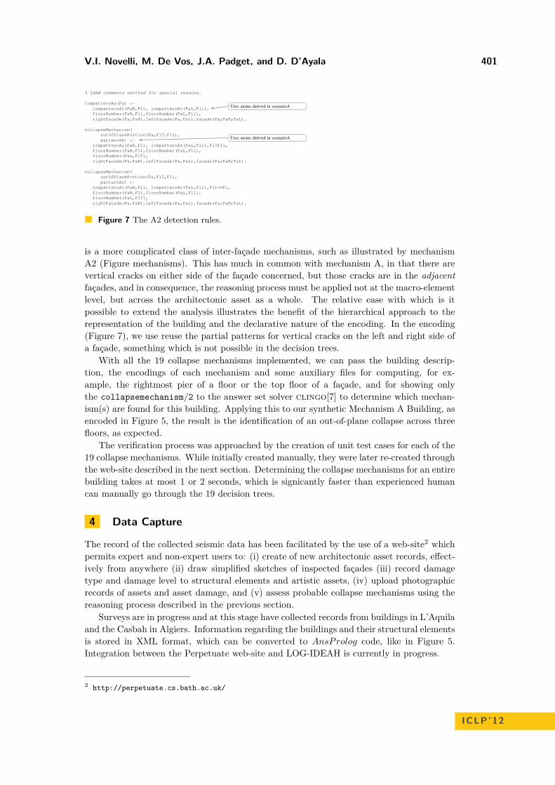
Figure 7 The A2 detection rules.
is a more complicated class of inter-façade mechanisms, such as illustrated by mechanismA2 (Figure mechanisms). This has much in common with mechanism A, in that there arevertical cracks on either side of the façade concerned, but those cracks are in the adjacentfaçades, and in consequence, the reasoning process must be applied not at the macro-elementlevel, but across the architectonic asset as a whole. The relative ease with which is itpossible to extend the analysis illustrates the benefit of the hierarchical approach to therepresentation of the building and the declarative nature of the encoding. In the encoding(Figure 7), we use reuse the partial patterns for vertical cracks on the left and right side ofa façade, something which is not possible in the decision trees.
With all the 19 collapse mechanisms implemented, we can pass the building descrip-tion, the encodings of each mechanism and some auxiliary files for computing, for ex-ample, the rightmost pier of a floor or the top floor of a façade, and for showing onlythe collapsemechanism/2 to the answer set solver clingo[7] to determine which mechan-ism(s) are found for this building. Applying this to our synthetic Mechanism A Building, asencoded in Figure 5, the result is the identification of an out-of-plane collapse across threefloors, as expected.
The verification process was approached by the creation of unit test cases for each of the19 collapse mechanisms. While initially created manually, they were later re-created throughthe web-site described in the next section. Determining the collapse mechanisms for an entirebuilding takes at most 1 or 2 seconds, which is signicantly faster than experienced humancan manually go through the 19 decision trees.
4 Data Capture
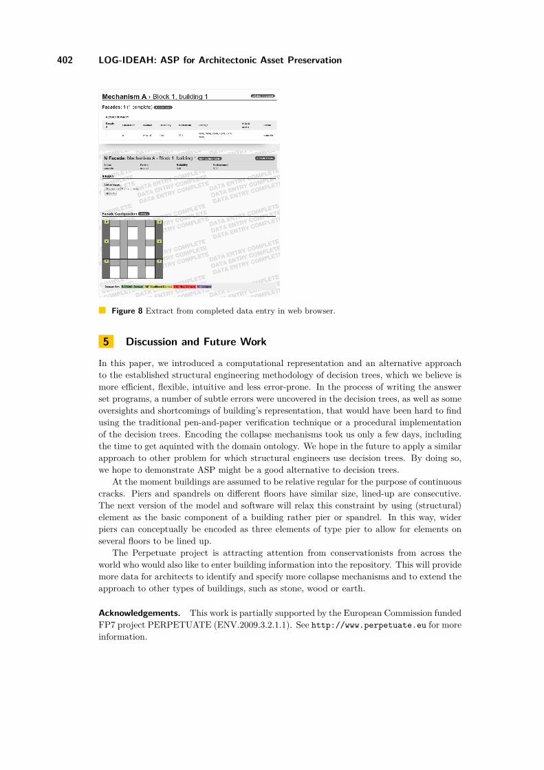
The record of the collected seismic data has been facilitated by the use of a web-site2 whichpermits expert and non-expert users to: (i) create of new architectonic asset records, effect-ively from anywhere (ii) draw simplified sketches of inspected façades (iii) record damagetype and damage level to structural elements and artistic assets, (iv) upload photographicrecords of assets and asset damage, and (v) assess probable collapse mechanisms using thereasoning process described in the previous section.
Surveys are in progress and at this stage have collected records from buildings in L’Aquilaand the Casbah in Algiers. Information regarding the buildings and their structural elementsis stored in XML format, which can be converted to AnsProlog code, like in Figure 5.Integration between the Perpetuate web-site and LOG-IDEAH is currently in progress.
2 http://perpetuate.cs.bath.ac.uk/
ICLP’12
402 LOG-IDEAH: ASP for Architectonic Asset Preservation
Figure 8 Extract from completed data entry in web browser.
5 Discussion and Future Work
In this paper, we introduced a computational representation and an alternative approachto the established structural engineering methodology of decision trees, which we believe ismore efficient, flexible, intuitive and less error-prone. In the process of writing the answerset programs, a number of subtle errors were uncovered in the decision trees, as well as someoversights and shortcomings of building’s representation, that would have been hard to findusing the traditional pen-and-paper verification technique or a procedural implementationof the decision trees. Encoding the collapse mechanisms took us only a few days, includingthe time to get aquinted with the domain ontology. We hope in the future to apply a similarapproach to other problem for which structural engineers use decision trees. By doing so,we hope to demonstrate ASP might be a good alternative to decision trees.
At the moment buildings are assumed to be relative regular for the purpose of continuouscracks. Piers and spandrels on different floors have similar size, lined-up are consecutive.The next version of the model and software will relax this constraint by using (structural)element as the basic component of a building rather pier or spandrel. In this way, widerpiers can conceptually be encoded as three elements of type pier to allow for elements onseveral floors to be lined up.
The Perpetuate project is attracting attention from conservationists from across theworld who would also like to enter building information into the repository. This will providemore data for architects to identify and specify more collapse mechanisms and to extend theapproach to other types of buildings, such as stone, wood or earth.
Acknowledgements. This work is partially supported by the European Commission fundedFP7 project PERPETUATE (ENV.2009.3.2.1.1). See http://www.perpetuate.eu for moreinformation.

V.I. Novelli, M. De Vos, J.A. Padget, and D. D’Ayala 403
References1 Chitta Baral. Knowledge Representation, Reasoning, and Declarative Problem Solving.
Cambridge University Press, Cambridge, England, 2003.2 D D’Ayala and E Speranza. Definition of collapse mechanisms and seismic vulnerability of
historic masonry buildings. Earthquake Spectra, 19:479—509, August 2003.3 D. F. D’Ayala. Force and displacement based vulnerability assessment for traditional build-
ings. Bulletin Of Earthquake Engineering, 3:235—265, December 2005.4 Dina D’Ayala and Sara Paganoni. Assessment and analysis of damage in l’aquila his-
toric city centre after 6th april 2009. Bulletin of Earthquake Engineering, 9:81–104, 2011.10.1007/s10518-010-9224-4.
5 Marina De Vos, Doga Kiza, Johannes Oetsch, Jörg Pührer, and Hans Tompits. Annotatinganswer-set programs in lana. Theory and Practice of Logic Programming, 2012.
6 Thomas Eiter, Nicola Leone, Cristinel Mateis, Gerald Pfeifer, and Francesco Scarcello. TheKR system dlv: Progress report, comparisons and benchmarks. In Proceedings of the 6thInternational Conference on Principles of Knowledge Representation and Reasoning (KR1998), pages 406–417. Morgan Kaufmann, 1998.
7 M. Gebser, B. Kaufmann, A. Neumann, and T. Schaub. Conflict-driven answer set solving.In Proceedings of the 20th International Joint Conference on Artificial Intelligence (IJCAI2007), pages 386–392. AAAI Press/The MIT Press, 2007.
8 Michael Gelfond and Vladimir Lifschitz. The stable model semantics for logic programming.In Proceedings of the 5th International Conference and Symposium on Logic Programming,pages 1070–1080. MIT Press, 1988.
9 Michael Gelfond and Vladimir Lifschitz. Classical negation in logic programs and disjunct-ive databases. New Generation Computing, 9(3-4):365–386, 1991.
10 Viviana Novelli and Dina D’Ayala. Seismic damage identification of cultural heritage assets.In Seismic Protection of Curtural Heritage, page 13, Antalya, Turkey, 2011.
ICLP’12
Related Documents