Localized Hybridization Circuits Harish Chandran 1 , Nikhil Gopalkrishnan 1 , Andrew Phillips 2 , and John Reif 1 1 Department of Computer Science, Duke University {harish,nikhil,reif}@cs.duke.edu 2 Microsoft Research [email protected] Abstract. Molecular computing executed via local interactions of spa- tially contiguous sets of molecules has potential advantages of (i) speed due to increased local concentration of reacting species, (ii) generally sharper switching behavior and higher precision due to single molecule interactions, (iii) parallelism since each circuit operates independently of the others and (iv) modularity and scalability due to the ability to reuse DNA sequences in spatially separated regions. We propose detailed designs for local molecular computations that involve spatially contigu- ous molecules arranged on addressable substrates. The circuits act via enzyme-free DNA hybridization reaction cascades. Our designs include composable OR, AND and propagation Boolean gates, and techniques to achieve higher degree fan-in and fan-out. A biophysical model of lo- calized hybridization reactions is used to estimate the effect of locality on reaction rates. We also use the Visual DSD simulation software in conjunction with localized reaction rates to simulate a localized circuit for computing the square root of a four bit number. 1 Introduction Molecular computation (MC) is computation executed at the molecular scale. Since the seminal work of Adleman[1], many DNA based computation schemes have been proposed. We will be discussing MCs that use strands of DNA to store state and execute various reactions that involve DNA hybridization and DNA strand displacement processes. DNA hybridization is the non-covalent binding of two complementary DNA sequences to form a single duplex structure. DNA strand displacement is the displacement of a single strand of DNA from a double helix by an incoming strand with a longer complementary region to the template strand. The incom- ing strand has a toehold, an empty single stranded region on the template strand complementary to a subsequence of the incoming strand, to which it binds ini- tially. It eventually displaces the outgoing strand via a kinetic process modeled as a one-dimensional random walk. Strand displacement is a key process in DNA nanoscience and many DNA nanosystems relying on DNA strand displacement have been demonstrated, ranging from DNA walkers[2] to catalytic circuits[3][4] to molecular detectors[5]. L. Cardelli and W. Shih (Eds.): DNA 17, LNCS 6937, pp. 64–83, 2011. c Springer-Verlag Berlin Heidelberg 2011

Welcome message from author
This document is posted to help you gain knowledge. Please leave a comment to let me know what you think about it! Share it to your friends and learn new things together.
Transcript
Localized Hybridization Circuits
Harish Chandran1, Nikhil Gopalkrishnan1, Andrew Phillips2, and John Reif1
1 Department of Computer Science, Duke University{harish,nikhil,reif}@cs.duke.edu
2 Microsoft [email protected]
Abstract. Molecular computing executed via local interactions of spa-tially contiguous sets of molecules has potential advantages of (i) speeddue to increased local concentration of reacting species, (ii) generallysharper switching behavior and higher precision due to single moleculeinteractions, (iii) parallelism since each circuit operates independentlyof the others and (iv) modularity and scalability due to the ability toreuse DNA sequences in spatially separated regions. We propose detaileddesigns for local molecular computations that involve spatially contigu-ous molecules arranged on addressable substrates. The circuits act viaenzyme-free DNA hybridization reaction cascades. Our designs includecomposable OR, AND and propagation Boolean gates, and techniquesto achieve higher degree fan-in and fan-out. A biophysical model of lo-calized hybridization reactions is used to estimate the effect of localityon reaction rates. We also use the Visual DSD simulation software inconjunction with localized reaction rates to simulate a localized circuitfor computing the square root of a four bit number.
1 Introduction
Molecular computation (MC) is computation executed at the molecular scale.Since the seminal work of Adleman[1], many DNA based computation schemeshave been proposed.
We will be discussing MCs that use strands of DNA to store state and executevarious reactions that involve DNA hybridization and DNA strand displacementprocesses. DNA hybridization is the non-covalent binding of two complementaryDNA sequences to form a single duplex structure. DNA strand displacement isthe displacement of a single strand of DNA from a double helix by an incomingstrand with a longer complementary region to the template strand. The incom-ing strand has a toehold, an empty single stranded region on the template strandcomplementary to a subsequence of the incoming strand, to which it binds ini-tially. It eventually displaces the outgoing strand via a kinetic process modeledas a one-dimensional random walk. Strand displacement is a key process in DNAnanoscience and many DNA nanosystems relying on DNA strand displacementhave been demonstrated, ranging from DNA walkers[2] to catalytic circuits[3][4]to molecular detectors[5].
L. Cardelli and W. Shih (Eds.): DNA 17, LNCS 6937, pp. 64–83, 2011.c© Springer-Verlag Berlin Heidelberg 2011
Localized Hybridization Circuits 65
1.1 Local versus Global MC
We distinguish two types of MC:
• A MC is local if its state is encoded by a spatially contiguous set of moleculesi.e., the state of each computing element is explicitly determined by the config-uration of these molecules, and transitions of state are executed via interactionsbetween local computing elements. An example of a purely local MC is whiplashPCR of Sakamoto et al.[6] in which the computation state is present within asingle molecule, and state transitions are executed via polymerization reactionson that molecule. This paper gives a detailed description of a novel local MCusing only DNA hybridization and no enzymatic reactions.
• In contrast, a MC is global if the state of the device is spatially distributedi.e., the state is determined by averaging the concentration and configurationof spatially distributed molecules that define state, and transitions of state areexecuted via multiple distributed interactions. An example of global MC is DNAreaction networks such as seesaw gates of Qian and Winfree[7] where all elemen-tary logical operations (e.g., logical AND and OR) are performed via a host ofdiffusion based strand displacement interactions.
Note that other MC may combine local and global; for example the tile assemblyof Rothemund and Winfree[8] performs computation by incorporating moleculesinto a growing assembly.
1.2 Motivation for Local MC
We discuss some potential advantages of local MC over global MC by also con-sidering conventional computing devices. Decades of ingenious improvements(e,g., digital behavior, locality of memory, and local parallelism) to the designof conventional computing devices have allowed their performance to be vastlyimproved, providing optimizations beyond the improvements due purely to fab-rication technology. We aim in this paper to exploit key aspects of these designsin our designs of local MCs.
Execution Speedup via Locality of Memory: In conventional computingdevices such as digital processors data is stored locally wherever possible andonly when the local memory limitations are exhausted is memory repositionedin more distributed locations. Hence conventional computing devices exploit lo-cality as a critical method to improve execution time for both memory accessand processing. It is reasonable that locality also be critical to the design of MCdevices.
In local MC, because the dominant interactions of a molecule involve a fixedset of neighbors, we can preferentially speed up designed interactions over spuri-ous ones. In contrast, in a global MC, such as a DNA hybridization circuit, thespeed of execution is severely limited by diffusion processes, which are stochas-tic processes whose rates are governed by the mobility and concentration of themolecules. In particular, the rate of hybridization of two complementary freelyfloating DNA strands (of moderate length) in a dilute buffer solution is limited
66 H. Chandran et al.
by the frequency of collisions between these DNA strands, since these moleculesmust first find each other by the much slower diffusion reaction prior to the sub-sequent hybridization reaction that occurs after they contact each other[9], [10].The rate of diffusion can be adjusted, but is ultimately limited by pragmatic con-siderations. Note that in a global MC, such as a DNA hybridization circuit, themobility of molecules can be increased by increasing the temperature, but this islimited to be at most the melting temperature of the hybridization. Alternately,one can attempt in a global MC to increase the rate of collisions by increasingthe concentration of the molecules, but this also increases the rate of spuriousreactions (e.g., unintended hybridization and/or dehybridizations, etc), by thesame factor. Hence, ultimately the computation rate of such global MCs is lim-ited by diffusion rates, not the local reaction rates. This implies that global MCs,such as DNA hybridization networks which rely on diffusion at each step, may beinherently slower than local MCs where the local concentration of the reactingspecies results in collision rates that are several orders of magnitude larger.
Digital Behavior in Conventional Computing Devices: In conventionaldigital computing machines the digital behavior of switches is a fundamentalbuilding block and it is reasonable that they would also be critical to the designof MC devices. Bi-stable devices that are used to simulate switches exhibit analogbehavior as they execute switching transitions. A sharper transition leads tofaster switching times. Greater activation energies for the switching transitionlead to increased robustness of the device. These two factors together decidethe digital behavior of the device. This sharp digital behavior seems likely to beuseful in incorporating variants of techniques (such as fault tolerance) perfectedfor standard silicon based digital devices into the design of MC devices. Thereare considerable differences in the digital behavior of local and global MC:
• Circuits implemented by local MC using spatially contiguous molecules ex-hibit sharp switching behavior within the computing unit. In particular, thestate of each computing element is explicitly determined by the configuration ofthese molecules, so is unambiguous and digital in nature.
• In contrast, circuits implemented by global MC such as DNA hybridizationreaction networks exhibit analog behavior that can be translated into digitalbehavior only by applying thresholds. In particular, the state of a global MCis determined by averaging the concentration and configuration of spatially dis-tributed molecules that define state, and so is an analog value.
Local Parallelism in Conventional Computing Devices: Modern-day con-ventional computing devices exploit parallel processing at many levels, both at thelocal processor chip as well as in multi-core architectures, to allow computationsto progress along different computational paths in parallel. MC can exploit localparallelism to allow multiple distinct local MCs to progress along different compu-tational paths in parallel. For example, a plethora of programmable nanomanufac-turing systems have been demonstrated[11][12]. These nanomanufacturingsystems require the state information to be stored locally so that different prod-ucts can be assembled in parallel in different molecules. Even if only a single
Localized Hybridization Circuits 67
product is targeted, different instances of the same product might be at differentstages of manufacture at any given time. This requires the state information tobe stored locally and is ideally suited for local molecular computing. In contrast,it is not evident how to implement this local control in a global MC.
Modularity: In conventional computing, devices generally contain multipleidentically designed computational units that act as modules in the overall archi-tecture and considerably simplify the overall design. In MC, we can expect thatmodularity will also be a critical aspect of the design and in large part relatesto DNA sequence reusability:
• Local MC involves interactions only with a fixed set of neighbors of eachmolecule and this enables distinct namespaces across molecules and opens uppossibilities of sequence reuse in the system. In particular, since our local DNAhybridization circuits are spatially separated and cannot directly interact, wecan reuse the same DNA sequences to build the same functionality (e.g., DNAhybridization circuit for a given logical operation) on a different part of thesystem using very few distinct DNA sequences in the overall design.
• Global MC on the other hand involves interactions among DNA strandsthat can be present anywhere in the reacting vessel, which implies a singleglobal namespace for the sequences, and hence considerably limits DNA sequencereusability.
1.3 Our Contribution and Paper Organization
We develop detailed designs to implement DNA circuits on fully addressableDNA nanostructures such as a fully addressable lattice developed by Yan etal.[13] or DNA origami developed by Rothemund[14]. In doing so we develop alocal molecular computing methodology to compute arbitrary Boolean functions.Our circuits are designed carefully to place downstream gates close enough toupstream gates to implement rapid signal transduction but far enough to mini-mize leaks. We argue that our circuits will: (i) be faster than chemical reactionnetworks due to increased local concentration of reacting species, (ii) exhibitgenerally sharper switching behavior and higher precision due to single moleculeinteractions, (iii) be highly parallel since each circuit operates independently ofthe others which finds use in nanomanufacture (iv) be modular and scalabledue to the ability to reuse DNA sequences in spatially separated regions. Weestimate the effect of locality on reaction rates via a biophysical model of local-ized hybridization reactions. We then use the Visual DSD simulation softwarein conjunction with these localized reaction rates to simulate a localized circuitfor computing the square root of a four bit number.
1.4 Prior Work
In theory it is possible to perform arbitrary computations using DNA strands,ignoring issues of errors, scale and time. Current experimental demonstrationsare far from this ideal. Synthetically designed DNA nanosystems currently can-not be leveraged to perform computationally complex biochemical tasks. The
68 H. Chandran et al.
need is for DNA circuits that are autonomous, error-resilient, scalable, fast andenergy efficient. We review progress toward this goal over the past decade.
Catalytic DNA Circuits: Zhang et al.[3] argued that autonomous, scalablecircuits require signal amplification and proposed catalysis as a means of achiev-ing amplification. Their entropy-driven catalytic gate achieved an auto-catalyticexponential amplification of a DNA signal, as opposed to linear amplification[5].The free energy for this reaction is a result of entropic gain due to dissociation ofweakly-bound DNA strands. At the same time, Yin et al.[4] also illustrated thepower of catalysis by demonstrating catalyzed formation of branched structures,auto-catalytic exponential amplifiers, dendritic growth and bipedal walkers. Allthese reactions were executed using an elementary hairpin motif with distinctfunctional sequence domains, allowing the reaction network to be abstracted bya simple visual symbolic language. These papers establish catalysis as a robustparadigm for constructing amplifying DNA gates.
Composable DNA Gates: The next challenge is to integrate catalytic DNAgates into large circuits. Qian and Winfree[15] proposed the simple and elegantseesaw gate, a modification of the catalytic gate of Zhang et al.[3] to makeit composable. All toehold domains in the seesaw gate are identical, allowingfor modular design of the circuit and parallel synthesis of many gates. Usingthe seesaw gates, Qian and Winfree[7] were able to demonstrate a non-trivialcomputation using hundreds of gates. The key obstacle toward further scalingup their circuit is the speed of operation. Since the seesaw gates are freely floatingin solution, the reaction rates are primarily limited by the time it takes for DNAstrands to encounter each other via diffusion. The authors take note of this issueand suggest moving their circuits to origami to speed-up hybridization kinetics,avoid cross talk and re-use sequences in spatially separate locations. This workexpands upon those ideas.
Two Domain Fork and Join Gates: Cardelli[16] developed designs for trans-duction, fork and join gates using DNA strands limited to two domains. He an-alyzed the power of systems composed of these 3 basic gates, proved that theyare equivalent to Petri nets and simulated various systems specified in this twodomain language. Our independently derived designs for AND, OR and PROP-AGATION gates are similar to the fork and join gates described in this work.
Addressable DNA Substrates: We develop designs that implement DNA hy-bridization circuits on fully addressable substrates. Much experimental progresshas been achieved in the area of addressable DNA substrates. Park et al.[17]demonstrated a fully addressable lattice built out of the cross tile developedby Yan et al.[13]. This was later extended to an 8 × 8 fully addressable latticeby Pistol and Dwyer[18] using hierarchical assembly techniques. Rothemund[14]developed the technique of DNA origami in which a long scaffold DNA strandobtained from a viral genome is folded into the desired shape by the use of hun-dreds of short synthetic DNA strands called staples. Each staple strand bindsto the scaffold strand at precisely two locations thereby localizing two distinctpoints on the scaffold strand. Hundred such stapling events fold the scaffold
Localized Hybridization Circuits 69
into the desired shape. Origami has been widely used as a substrate to ar-range various molecules[12][19] and has been extended to form three dimensionalshapes[20][21].
2 Design of DNA Hybridization Circuits on AddressableDNA Substrates
We begin by designing two composable DNA hybridization driven gates thatperform AND and OR Boolean logic. An additional propagation gate serves asa wire and propagates signal. The gates are implemented as a cascade of toeholdmediated strand displacement reactions. Each of these reactions is initiated viaa universal toehold binding domain (labeled ˜T ) whose sequence is the samethroughout the circuit. The specificity of strand displacement is conferred bya set of specificity domains (labeled ˜Si) that are unique to each gate. We assumethat there exists an irreversible downstream drain (not shown in the figures) foreach gate.
The gates can be precisely positioned on the fully addressable DNA substrateby designing them as extensions of conventional substrate strands. The actualpositioning of the gates depends on the digital circuit being implemented. Inparticular, gates that are connected to each other are placed close to each other.In this sense, the localized DNA circuit mimics the topology of the actual dig-ital circuit diagram. Each localized circuit structure contains one copy of eachgate in the circuit and operates by signaling across gates via single molecules,eliminating the need for signal restoration.
Any boolean function can be implemented using purely AND and OR gatesby the use of dual rail logic, which uses two bits each to encode 0 and 1. Thepropagation gate is used to control the relative positions of the AND and ORgates on the substrate so that the circuit elements can function correctly withoutsteric interference.
2.1 Design of Logical Gates
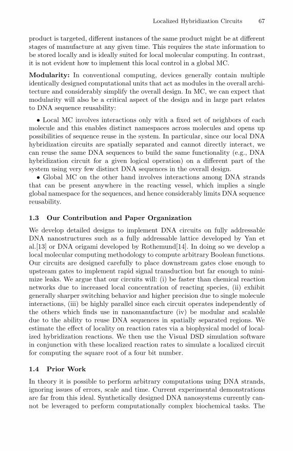
Figure 1 illustrates how two hairpin motifs are used to achieve OR logic. Forinput domains Si1 and Si2 we design motifs with the sequences Si1TSo
˜T ˜Si1˜T and
Si2TSo˜T ˜Si2
˜T respectively where ˜Si1 and ˜Si2 are the input recognition domainsand So is the output domain. In the presence of either the sequence TSi1 or TSi2 ,one of the hairpins opens up to reveal the output So as illustrated in Figure 1.Note that the reaction that opens the hairpin is irreversible in the presence of adownstream gate that consumes So.
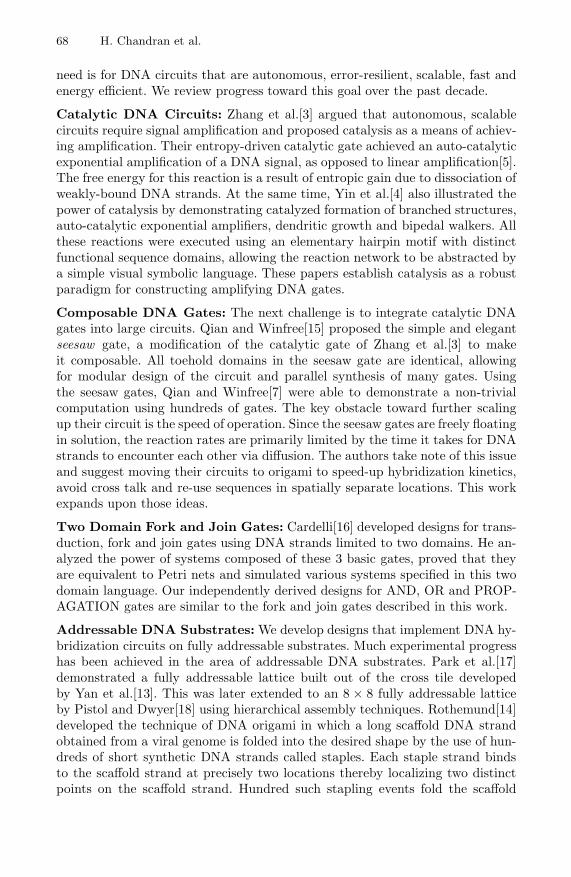
Figure 2 illustrates a two input AND gate complex consisting of a hairpinmotif and a protector strand. For input domains Si1 and Si2 , the hairpin mo-tif has sequence Si2TSo
˜T ˜Si2˜T ˜Si1
˜T and is hybridized to the protector that hassequence Si1T . The sequences ˜Si1 and ˜Si2 are the input recognition domainsand So is the output domain. In the presence of the sequence TSi1 the protec-tor is displaced out of the complex exposing a universal toehold domain ˜T . If the
70 H. Chandran et al.
Fig. 1. The OR gate computing the Boolean function Si1 + Si2 . It is implemented bytwo green strands Si1TSo
˜T ˜Si1˜T and Si2TSo
˜T ˜Si2˜T . The inputs are TSi1 and TSi2 .
The presence of either of these input strands triggers the exposure of the output TSo
which is initially sequestered in a hairpin.
Fig. 2. The AND gate computing the Boolean function Si1 · Si2 . It is implemented bya complex consisting of the green strand Si2TSo
˜T ˜Si2˜T hybridized to the light green
strand Si1T . The inputs are TSi1 and TSi2 . The presence of both of these input strandstriggers the exposure of the output TSo which is initially sequestered in a hairpin.
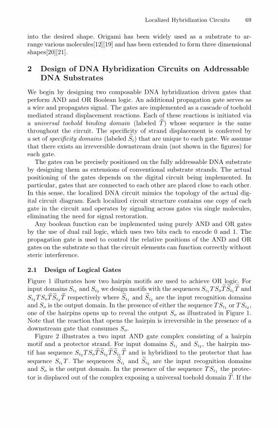
Fig. 3. The Propagation gate enables the signal transduction Si → So. It is imple-mented by a green strand SiTSo
˜T ˜Si˜T The input TSi triggers the exposure of the
output TSo which is initially sequestered in a hairpin.
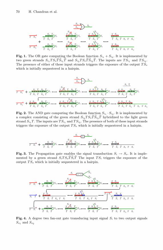
Fig. 4. A degree two fan-out gate transducing input signal Si to two output signalsSo1 and So2
Localized Hybridization Circuits 71
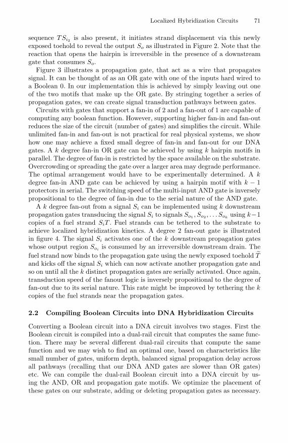
sequence TSi2 is also present, it initiates strand displacement via this newlyexposed toehold to reveal the output So as illustrated in Figure 2. Note that thereaction that opens the hairpin is irreversible in the presence of a downstreamgate that consumes So.
Figure 3 illustrates a propagation gate, that act as a wire that propagatessignal. It can be thought of as an OR gate with one of the inputs hard wired toa Boolean 0. In our implementation this is achieved by simply leaving out oneof the two motifs that make up the OR gate. By stringing together a series ofpropagation gates, we can create signal transduction pathways between gates.
Circuits with gates that support a fan-in of 2 and a fan-out of 1 are capable ofcomputing any boolean function. However, supporting higher fan-in and fan-outreduces the size of the circuit (number of gates) and simplifies the circuit. Whileunlimited fan-in and fan-out is not practical for real physical systems, we showhow one may achieve a fixed small degree of fan-in and fan-out for our DNAgates. A k degree fan-in OR gate can be achieved by using k hairpin motifs inparallel. The degree of fan-in is restricted by the space available on the substrate.Overcrowding or spreading the gate over a larger area may degrade performance.The optimal arrangement would have to be experimentally determined. A kdegree fan-in AND gate can be achieved by using a hairpin motif with k − 1protectors in serial. The switching speed of the multi-input AND gate is inverselypropositional to the degree of fan-in due to the serial nature of the AND gate.
A k degree fan-out from a signal Si can be implemented using k downstreampropagation gates transducing the signal Si to signals So1 , So2 , . . . Sok
using k−1copies of a fuel strand SiT . Fuel strands can be tethered to the substrate toachieve localized hybridization kinetics. A degree 2 fan-out gate is illustratedin figure 4. The signal Si activates one of the k downstream propagation gateswhose output region Soi is consumed by an irreversible downstream drain. Thefuel strand now binds to the propagation gate using the newly exposed toehold ˜Tand kicks off the signal Si which can now activate another propagation gate andso on until all the k distinct propagation gates are serially activated. Once again,transduction speed of the fanout logic is inversely propositional to the degree offan-out due to its serial nature. This rate might be improved by tethering the kcopies of the fuel strands near the propagation gates.
2.2 Compiling Boolean Circuits into DNA Hybridization Circuits
Converting a Boolean circuit into a DNA circuit involves two stages. First theBoolean circuit is compiled into a dual-rail circuit that computes the same func-tion. There may be several different dual-rail circuits that compute the samefunction and we may wish to find an optimal one, based on characteristics likesmall number of gates, uniform depth, balanced signal propagation delay acrossall pathways (recalling that our DNA AND gates are slower than OR gates)etc. We can compile the dual-rail Boolean circuit into a DNA circuit by us-ing the AND, OR and propagation gate motifs. We optimize the placement ofthese gates on our substrate, adding or deleting propagation gates as necessary.
72 H. Chandran et al.
The sequence design for the gate motifs is modular and we simply design allbinding domains so as to minimize spurious interactions. Techniques for domainlevel sequence design have been discussed by Zhang[22].
In practice, we may incorporate further optimizations in designing our DNAcircuits rather than compiling them directly. For instance, we may wish to targetcertain leaky portions of the circuit and make them more fault tolerant by, forinstance, replicating the circuit module and taking the majority. Such techniquesto increase robustness of circuits are well studied in the VLSI community andit is likely that the algorithmic solutions found there may be translated simplyinto DNA circuits because of the digital gate level abstraction that we provide.
2.3 Assembly of DNA Hybridization Circuits on Addressable DNANanostructures
In this section we illustrate two methods to organize DNA circuits on addressableDNA substrates by highly parallel synthesis that is experimentally feasible andscales to large number of gates.
Pistol and Dwyer[18] have demonstrated the assembly of fully addressableDNA lattices of size up to 8 × 8 using hierarchical assembly techniques. Thehierarchical assembly can be parallelized and has the potential to be scaledbeyond 8 × 8 lattices. We use this approach to organize our circuits on DNAlattices. Each DNA gate motif is designed as an extension of one of the strandsthat is part of the tile that assembles into a lattice. Since each tile in the finallyformed lattice is uniquely addressable, the motifs can be precisely and specificallypositioned on the lattice according to the circuit being implemented.
Rothemund[14] demonstrated the breakthrough DNA origami technique formanufacturing large, fully addressable DNA nanostructures with high yield in asingle pot reaction. Each designed hybridization interaction in a DNA origamistructure is between a staple and a region of the scaffold. No staple-staple orscaffold-scaffold interactions are designed. Thus, even if the relative concentra-tions of the staples are imprecise, the final yield of the origami structure remainshigh as long as an excess (about 10×) of staple strands is used. We use the sameapproach to organize our circuits on DNA origami. Each DNA gate motif is anextension of a staple strand. Since the surface of the origami is uniquely ad-dressable, the motifs can be precisely and specifically positioned on the origamiaccording to the circuit being simulated.
The key cause for concern is that when annealed, the hairpin strands willinteract with each other rather than folding up into the required hairpin motif.However, there is evidence that when annealed, dilute (≈ nM concentrations)interacting strands undergo uni-molecular reactions and fold up into hairpin mo-tifs rather than hybridizing with each other via bi-molecular reactions[23]. Thisis explained by noting that the hairpin structure is stable at a higher temper-ature than the intermolecular complex and as the system is cooled, the motifsform hairpins first getting kinetically trapped in the non-optimal thermodynamicstate. It is unclear if this assumption holds when the strands are locally concen-trated, for instance, by tethering them close to each other. To avoid this problem,
Localized Hybridization Circuits 73
we design our motifs such that their hairpin structure is stable at higher tem-peratures than both the temperature at which they are stably incorporated intothe substrate and the temperature at which the bimolecular complex is stable.When annealed, we expect the hairpin motif to form while the strands are diluteand not yet tethered to the substrate, and then the motifs are incorporated intothe substrate.
Since the OR motifs are simply single stranded hairpins, this is easily achievedby making the length of the specificity domain moderately longer than the lengthby which the motif is tethered to the origami. In practice, the tether length couldbe 16 bases while the length of the specificity domain could be 20 and the toeholddomain could be 5 bases, making the stem of the OR hairpin motif 25 bases long.The AND motif is slightly more problematic since it is a two strand complex - aprotector strand hybridized to a hairpin motif. By choosing lengths of 20 and 5bases for the specificity and toehold domains we can ensure that the protector-hairpin complex is stable at a higher temperature than the temperature at whichthe origami tether is stable. However, an upstream input to the AND motif wouldhave similar stability with the AND hairpin as the protector-hairpin complex asboth are bimolecular reactions. This difficulty can be overcome in one of two ways.We can anneal the protector-hairpin complex separately, purify it and then addit to the origami mix. While annealing the origami mix we take care to not heatthe sample above the melting temperature of the protector-hairpin complex. Al-ternately, we design the AND motif as a single hairpin motif and cleave the motifat the appropriate site after annealing by using a nicking enzyme. For this pur-pose we can design the toehold sequence as the recognition domain of a nickingenzyme which cleaves one of the strands of a double helix upstream of its recog-nition site. Note that a single nicking enzyme would be sufficient to prepare allprotector-hairpin complexes and this process could be implemented in parallel.Also, the restriction enzyme won’t nick the OR hairpin motifs as the correspond-ing position in these structures is single stranded.
2.4 Reusing Sequences in Spatially Separated Circuits
In the circuits we have discussed thus far, each distinct circuit element (wiresand gates) is implemented by a distinct DNA sequence that is never reused. Thisimmediately places an upper bound on the complexity of the circuits since lengthof DNA sequences constituting each type of circuit element is fixed. Moreover,assigning distinct sequences to different copies of the same circuit element mightresult in variance in their operational characteristics.
If the gates in a circuit are spatially separated into clusters such gates caninteract directly only with other members of the cluster they belong to, thensequences can be reused across different clusters. Information is exchanged be-tween clusters via signal transduction pathways. In the extreme case, one canimagine a cluster to be a single gate and that each such gate is connected toother gates via long signal transduction pathways. These pathways composed ofmultiple propagation gates can also benefit from domain reuse. For example thek long pathway W1 → W2 → W2 → . . . Wk can be replaced by an equivalent k
74 H. Chandran et al.
long pathway Wa → Wb → Wa → . . .Wb. Care should be taken when sequencesare reused in signal transduction pathways running close to each other or cross-ing over one another. In such cases, signal flow across one pathway might initiatea spurious signal flow across the other if pathways share same sequences. Suchproblematic areas in the circuit can use unique sequences to minimize crosstalk.
Reusing DNA sequences to build the same functionality on a different partof the DNA hybridization circuit allows us to build complex circuits with veryfew distinct DNA sequences. Here we use the key property that our local DNAhybridization circuits (for example a DNA hybridization circuit for a given logicaloperation) are spatially separated and so cannot directly interact. While thesequence domains that take part in circuit interactions are reused, the tethersequences that position the elements on an addressable substrate can be distinct(eg. in DNA origami) or can be reused (eg. in hierarchical assembly).
2.5 Functional Units and Architectures
We have discussed how to build digital circuits using DNA sequences on an ad-dressable substrate. We can build complex circuits via a hierarchical method.Small substrates can implement functional units that can be connected in a pre-cise manner to synthesize computing architectures. The hierarchical assemblyprocess developed by Park et al.[24] can be directly applied to build such cir-cuits using tile based assemblies. If origami is used as a substrate, then differentorigami can be connected to each other via sticky ends to form larger assemblies.One could also think of using a secondary scaffold to organize different origamiin a precise manner to enable information flow between them. One simple layoutfor such architecture would be to have the computing elements in the middle ofthe origami and connect them up to neighboring origami via long signal trans-duction pathways that terminate at the edge of the origami. An advantage ofusing such architectures is the ability to ”plug and play” various functional units.For example, if we have designed and experimentally tested a set of functionalunits, say an adder, subtracter and square rooter, then we can build circuits thatare composed of these functions by plugging these units into precise positions onthe assembly. These functional units could be designed to ensure that they cancommunicate via the same signal transduction pathways for each input/outputbit so that they can be composed seamlessly.
3 Modeling and Simulations of Tethered Systems
In this section we investigate the speedups obtained in localized hybridizationcircuits as follows: (i) We develop a simple biophysical model of tethered hy-bridization and estimate values for a toehold binding speedup factor λ whichdepends on parameters of the design of the tethers. Our biophysical model oftethered hybridization closely follows the work of Genot et al.[25] and we usedata reported by Qian and Winfree[7] as a starting point for computing reac-tion rates. (ii) Then we use the Visual DSD system[26] to model and simulatea four bit square root circuit for various values of λ. We discuss some of theshortcomings of this simple model in section 4.1.
Localized Hybridization Circuits 75
3.1 A Biophysical Model of Tethered Hybridization
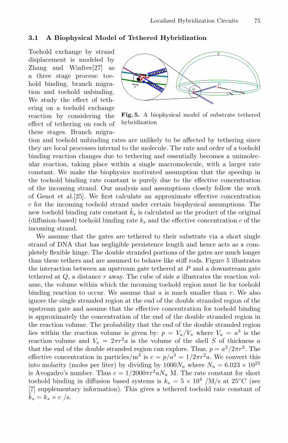
Fig. 5. A biophysical model of substrate tetheredhybridization
Toehold exchange by stranddisplacement is modeled byZhang and Winfree[27] asa three stage process: toe-hold binding, branch migra-tion and toehold unbinding.We study the effect of teth-ering on a toehold exchangereaction by considering theeffect of tethering on each ofthese stages. Branch migra-tion and toehold unbinding rates are unlikely to be affected by tethering sincethey are local processes internal to the molecule. The rate and order of a toeholdbinding reaction changes due to tethering and essentially becomes a unimolec-ular reaction, taking place within a single macromolecule, with a larger rateconstant. We make the biophysics motivated assumption that the speedup inthe toehold binding rate constant is purely due to the effective concentrationof the incoming strand. Our analysis and assumptions closely follow the workof Genot et al.[25]. We first calculate an approximate effective concentrationc for the incoming toehold strand under certain biophysical assumptions. Thenew toehold binding rate constant k̃s is calculated as the product of the original(diffusion-based) toehold binding rate ks and the effective concentration c of theincoming strand.
We assume that the gates are tethered to their substrate via a short singlestrand of DNA that has negligible persistence length and hence acts as a com-pletely flexible hinge. The double stranded portions of the gates are much longerthan these tethers and are assumed to behave like stiff rods. Figure 5 illustratesthe interaction between an upstream gate tethered at P and a downstream gatetethered at Q, a distance r away. The cube of side a illustrates the reaction vol-ume, the volume within which the incoming toehold region must lie for toeholdbinding reaction to occur. We assume that a is much smaller than r. We alsoignore the single stranded region at the end of the double stranded region of theupstream gate and assume that the effective concentration for toehold bindingis approximately the concentration of the end of the double stranded region inthe reaction volume. The probability that the end of the double stranded regionlies within the reaction volume is given by: p = Va/Vs where Va = a3 is thereaction volume and Vs = 2πr2a is the volume of the shell S of thickness athat the end of the double stranded region can explore. Thus, p = a2/2πr2. Theeffective concentration in particles/m3 is c = p/a3 = 1/2πr2a. We convert thisinto molarity (moles per liter) by dividing by 1000Na where Na = 6.023 × 10²³
is Avogadro’s number. Thus c = 1/2000πr2aNa M. The rate constant for shorttoehold binding in diffusion based systems is ks = 5 × 10⁴ /M/s at 25◦C (see[7] supplementary information). This gives a tethered toehold rate constant ofk̃s = ks × c /s.
76 H. Chandran et al.
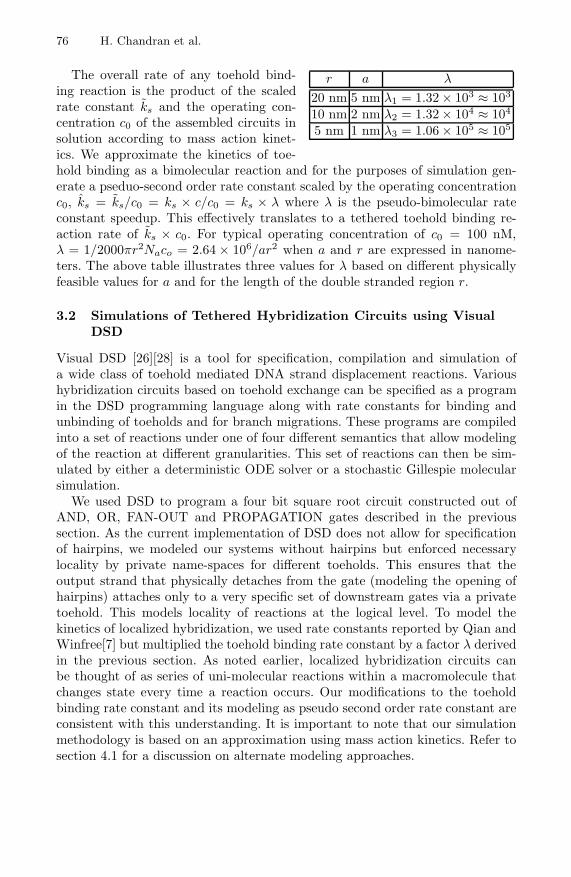
r a λ
20 nm 5 nm λ1 = 1.32 × 10³ ≈ 103
10 nm 2 nm λ2 = 1.32 × 10⁴ ≈ 104
5 nm 1 nm λ3 = 1.06 × 10⁵ ≈ 105
The overall rate of any toehold bind-ing reaction is the product of the scaledrate constant k̃s and the operating con-centration c0 of the assembled circuits insolution according to mass action kinet-ics. We approximate the kinetics of toe-hold binding as a bimolecular reaction and for the purposes of simulation gen-erate a pseduo-second order rate constant scaled by the operating concentrationc0, k̂s = k̃s/c0 = ks × c/c0 = ks × λ where λ is the pseudo-bimolecular rateconstant speedup. This effectively translates to a tethered toehold binding re-action rate of k̃s × c0. For typical operating concentration of c0 = 100 nM,λ = 1/2000πr2Naco = 2.64 × 10⁶/ar2 when a and r are expressed in nanome-ters. The above table illustrates three values for λ based on different physicallyfeasible values for a and for the length of the double stranded region r.
3.2 Simulations of Tethered Hybridization Circuits using VisualDSD
Visual DSD [26][28] is a tool for specification, compilation and simulation ofa wide class of toehold mediated DNA strand displacement reactions. Varioushybridization circuits based on toehold exchange can be specified as a programin the DSD programming language along with rate constants for binding andunbinding of toeholds and for branch migrations. These programs are compiledinto a set of reactions under one of four different semantics that allow modelingof the reaction at different granularities. This set of reactions can then be sim-ulated by either a deterministic ODE solver or a stochastic Gillespie molecularsimulation.
We used DSD to program a four bit square root circuit constructed out ofAND, OR, FAN-OUT and PROPAGATION gates described in the previoussection. As the current implementation of DSD does not allow for specificationof hairpins, we modeled our systems without hairpins but enforced necessarylocality by private name-spaces for different toeholds. This ensures that theoutput strand that physically detaches from the gate (modeling the opening ofhairpins) attaches only to a very specific set of downstream gates via a privatetoehold. This models locality of reactions at the logical level. To model thekinetics of localized hybridization, we used rate constants reported by Qian andWinfree[7] but multiplied the toehold binding rate constant by a factor λ derivedin the previous section. As noted earlier, localized hybridization circuits canbe thought of as series of uni-molecular reactions within a macromolecule thatchanges state every time a reaction occurs. Our modifications to the toeholdbinding rate constant and its modeling as pseudo second order rate constant areconsistent with this understanding. It is important to note that our simulationmethodology is based on an approximation using mass action kinetics. Refer tosection 4.1 for a discussion on alternate modeling approaches.
Localized Hybridization Circuits 77
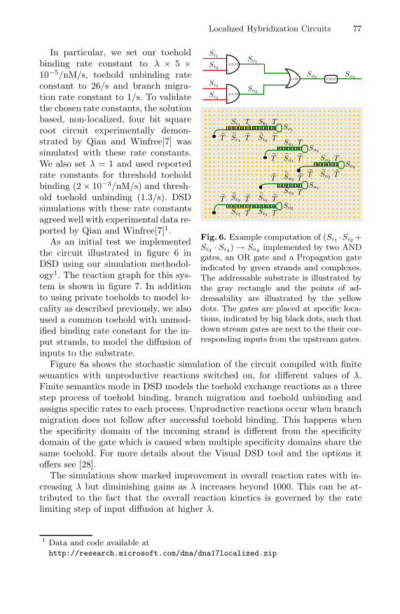
Fig. 6. Example computation of (Si1 ·Si2 +Si3 · Si4) → So4 implemented by two ANDgates, an OR gate and a Propagation gateindicated by green strands and complexes.The addressable substrate is illustrated bythe gray rectangle and the points of ad-dressability are illustrated by the yellowdots. The gates are placed at specific loca-tions, indicated by big black dots, such thatdown stream gates are next to the their cor-responding inputs from the upstream gates.
In particular, we set our toeholdbinding rate constant to λ × 5 ×10⁻⁵/nM/s, toehold unbinding rateconstant to 26/s and branch migra-tion rate constant to 1/s. To validatethe chosen rate constants, the solutionbased, non-localized, four bit squareroot circuit experimentally demon-strated by Qian and Winfree[7] wassimulated with these rate constants.We also set λ = 1 and used reportedrate constants for threshold toeholdbinding (2 × 10⁻³/nM/s) and thresh-old toehold unbinding (1.3/s). DSDsimulations with these rate constantsagreed well with experimental data re-ported by Qian and Winfree[7]1.
As an initial test we implementedthe circuit illustrated in figure 6 inDSD using our simulation methodol-ogy1. The reaction graph for this sys-tem is shown in figure 7. In additionto using private toeholds to model lo-cality as described previously, we alsoused a common toehold with unmod-ified binding rate constant for the in-put strands, to model the diffusion ofinputs to the substrate.
Figure 8a shows the stochastic simulation of the circuit compiled with finitesemantics with unproductive reactions switched on, for different values of λ.Finite semantics mode in DSD models the toehold exchange reactions as a threestep process of toehold binding, branch migration and toehold unbinding andassigns specific rates to each process. Unproductive reactions occur when branchmigration does not follow after successful toehold binding. This happens whenthe specificity domain of the incoming strand is different from the specificitydomain of the gate which is caused when multiple specificity domains share thesame toehold. For more details about the Visual DSD tool and the options itoffers see [28].
The simulations show marked improvement in overall reaction rates with in-creasing λ but diminishing gains as λ increases beyond 1000. This can be at-tributed to the fact that the overall reaction kinetics is governed by the ratelimiting step of input diffusion at higher λ.
1 Data and code available athttp://research.microsoft.com/dna/dna17localized.zip

78 H. Chandran et al.
Fig. 7. Reaction graph for the example circuit illustrated in figure 6 implementing theBoolean function x1 · x2 + x3 · x4. Initial species are highlighted with darker borders.Note that the input strands Tx1, Tx2, Tx3, Tx4 have a common universal toehold Twhose binding rate constant is set to 5×10⁻⁵/nM/s while the other toeholds are private(for example Ta2 is private to domain a2) and their binding rate constants are set toλ × 5 × 10⁻⁵/nM/s.
(a) Simulation data for circuit imple-menting x1 ·x2 +x3 ·x4 with inputs set tox1 = 1, x2 = 1, x3 = 0, x4 = 0 for differentλ. Simulation time: 300 seconds. Simula-tion carried out in finite mode with un-productive options on. Inset shows longerrun of system for λ = 1.
(b) Simulation data for output LSB fromthe square root circuit with input 1100 fordifferent λ. Simulation time: 600 seconds.Simulation carried out in finite modewith unproductive options on. Inset showslonger run of system for λ = 1, 10.
Fig. 8. Simulation data
Encouraged by these results we programmed a four bit square root circuit us-ing AND, OR and FAN-OUT gates described earlier. As before, we used privatetoeholds with modified binding rate constants to model locality and used a uni-versal toehold with standard rate constants to model diffusion of inputs. Figure8b shows data from simulations using DSD in finite mode with unproductivereactions switched on. We first simulated the four bit square root circuit for all
Localized Hybridization Circuits 79
input values with λ = 1 and found that the computation of the output LSBfor input 1100 was the slowest to 95% completion. Due to space considerationand in the spirit of worst case analysis, we show the behavior of this signal atdifferent values of λ. More data from our simulations is available at this URL1.As before, completion rates show dramatic improvements with increasing λ andthe overall kinetics is rate limited at higher λ by input diffusion (which roughlytakes 150 seconds at 100 nM).
4 Discussion
4.1 Refined Modeling and Simulations of Tethered Systems
All localized toehold binding interactions are assigned the same rate constantin our simulations. However, there are two types of localized toehold binding,one between regions on the same strand (resulting in hairpin formation) andanother between distinct strands. Our biophysical model only applies to thelatter case. A more careful analysis would include different binding rates in bothcases. The challenge of modeling and simulation of tethered systems is to modeluni-molecular reactions rather than the bimolecular reactions found in mostother conventional hybridizations reaction systems. Our biophysical model ispreliminary and ignores the worm-like chain behavior of single strands of DNA.A more detailed model may give a better estimation of local concentrations.
Molecular circuits tend to leak: downstream hybridization cascades are some-times set off by thermal noise even in the absence of upstream signals. Spurioushybridization interactions, either due to unintended sequence complementarityor unproductive interactions between complementary domains (e.g. universaltoehold binding), is another common problem. Sequence reuse can mitigate unin-tended sequence complementarity while careful positioning of interfering strandson the substrate can inhibit unproductive reactions. Nevertheless we expect leaksand unproductive reactions to exist, and hence the need for a model of leak re-actions in localized circuits. A fruitful approach may be to model the time tofailure of each gate as a random variable and use this to estimate the overallleak rate. We discuss some error-tolerance mechanisms in section 4.4.
We simulate tethered systems using mass action kinetics. An alternate ap-proach would be to model the entire network as a continuous time Markov chainand estimate (or simulate) its expected time to completion where the times tocompletion of toehold binding, branch migration and toehold unbinding couldbe estimated via DNA molecular dynamics. Our preliminary simulations (datanot shown) under this regime indicates higher speedups in tethered systems.Addressing these issues is beyond the scope of this paper and will be a part offuture work in tethered hybridization systems.
4.2 Optimizations
The circuits discussed thus far have only utilized one side of the addressablesurface. Suppose the substrate is addressable on both sides and the substrate is
80 H. Chandran et al.
stiff and dense enough to ensure that strands on one side cannot interact withthe strands on the other (note that these assumptions are true for certain DNAorigami). Then it is possible to use both sides of the substrate for implementingdifferent circuits. These circuits can still interact at the edges of the substratefor signal transduction.
The output of simple circuits could be a Boolean value requiring just onebit. The output of such computation can be detected via standard flurophore/quencher protocols. But complex circuits might output multiple bits or com-pute an integer requiring the detection of multiple bits. Though one can usemultiple flurophore/quencher pairs operating at various frequencies, it is quiteclear that this solution does not scale. One possible way to overcome this issueis to implement the circuit for each bit of the output in different test tubes.Once again, we can exploit the spatial separation of circuits to reuse the sameflurophore/quencher pair for every output bit.
To assemble large circuits on origami requires longer scaffolds. Naturally oc-curring long scaffolds might be problematic since they might exhibit strong sec-ondary structure or might interfere with the DNA sequences used for variousgates. If we use spatial separation to restrict ourselves to a small set of DNAsequences, we might mitigate the latter problem. The former problem might besolved by careful design of a synthetic scaffold.
4.3 Synchronous Computation and Nanomanufacture
The circuits described in this paper were asynchronous and used dual rail logic.It is possible to achieve synchronous lock-step computation using AND gates.For example, if we want one part of a circuit (say part B) to be activated onlyafter another part of the circuit (say part A) has finished its computation, theneach signal transduction pathway entering into B can be changed into the outputof the AND of that original pathway and a specific completion signal from partA. Thus part B is locked unless part A is complete. Alternating this strategyacross two circuits allows them to proceed in a lock-step fashion.
This technique can be extended to nanomanufacture applications. We canthink of the entire process having two components, a fabricating nanomachinelike a DNA walker and a computing logic that governs the action of the fabricat-ing device. The fabricating device and the computing logic can be operated inthe lock step fashion described earlier. The computation leading to this productformation can be governed by the actual inputs to the circuit.
4.4 Possible Errors and Techniques to Mitigate Them
Errors with localized DNA circuits can broadly be classified into two types:errors in organizing the gate motifs on the substrate and errors in operation. Thechief possible errors in organizing the motifs on the substrate are: (i) missingmotifs and (ii) damaged motifs due to incorrect folding, sequence truncationor formation of spurious bimolecular complexes. Techniques to deal with thesekinds of errors are discussed in section 2.3.
Localized Hybridization Circuits 81
Errors in operation are chiefly due to: (i) leaks via spontaneous opening ofthe hairpin motifs (ii) leaks via stacking induced strand displacement and (iii)spurious toehold binding. Spontaneous opening of the hairpin motifs are likely tobe rare at our operation conditions, since the stem of the hairpin is 25 bases. Werefer to the end of the stem at the loop region as the head of the motif and theother end as its tail. Stacking induced strand displacement is likely to occur viahead to tail stacking of motifs. The loop region is likely to sterically hinder suchstacking, destabilizing it. We will also experiment with carefully orienting themotifs on the origami surface such that these stackings strain the motif tetherregion and are hence sterically hindered. For instance the motifs likely to undergostacking could be oriented alongside each other. Since each motif has the sametoehold binding region, the output of one motif may bind to the toehold regionof a neighboring motif even if they are not designed to interact. This spuriousinteraction is prevented from setting off downstream reactions by the mismatchin the specificity domains. However, such reactions may block the toehold regionand slow down the operation of the circuit. This problem is present even withthe seesaw circuit of Qian and Winfree[7] but does not seem to significantlyaffect their correct operation for moderate circuit sizes. The spurious toeholdinteractions in our designs are restricted to the diameter of motifs reachable bythe tethered motif, in contrast to the seesaw circuits where it is a global problem.
In spite of these techniques, a certain level of leaks is unavoidable. If weassume that every copy of the circuit on origami has a fixed independent failureprobability of ε, then we expect that out of N targeted copies of the circuit,N(1 − ε) of them will function correctly. The final output of the circuit is theconsensus of the outputs across all copies of the circuit, with appropriately setthresholds based on the failure rate. Alternately, we can implement standardtechniques in fault tolerance into our circuits. This correction of errors at thelogical level has been used with great success in building of semiconductor basedcircuits and this provides inspiration in dealing with errors due to leaks.
5 Conclusions
Local bimolecular reactions have multiple advantages over global molecular com-putation. In this paper we have developed detailed designs to implement DNAcircuits on fully addressable DNA nanostructures such as a fully addressable lat-tice developed by Yan et al.[13] or DNA origami developed by Rothemund[14].In doing so we developed a local molecular computing methodology to com-pute arbitrary Boolean functions. Our circuits are designed carefully to placedownstream gates close enough to upstream gates to implement rapid signaltransduction but far enough to minimize leaks. We argued that our circuits will:(i) be faster than chemical reaction networks due to increased local concentrationof reacting species, (ii) exhibit generally sharper switching behavior and higherprecision due to single molecule interactions, (iii) be highly parallel since eachcircuit operates independently of the others which finds use in nanomanufacture
82 H. Chandran et al.
(iv) be modular and scalable due to ability to reuse DNA sequences in spatiallyseparated regions. A biophysical model of localized hybridization reactions wasused to estimate the effect of locality on reaction rates. We used the Visual DSDsimulation software in conjunction with these localized reaction rates to simulatea localized circuit for computing the square root of a four bit number.
This effort is a first attempt at realizing enzyme-free localized hybridizationcircuits. In light of the rapid growth of DNA nanotechnology, it is our hopethat the principles expounded in this paper will serve as a starting point for theeventual realization of localized hybridization circuits in the laboratory.
Acknowledgments. We wish thank to Erik Winfree, David Zhang and BernardYurke for useful discussions on the localized strand displacement process. Wethank anonymous referees for pointing out relevant prior work and critical sug-gestions on modeling of tethered systems. We would also like to thank SudhanshuGarg for assisting in creating figures for a preliminary draft and Archana Ra-mamoorthy for proof-reading. This work was supported by NSF EMT GrantsCCF-0829797 and CCF-0829798.
References
1. Adleman, L.: Molecular Computation of Solutions to Combinatorial Problems.Science 266(5178), 1021–1024 (1994)
2. Sherman, W., Seeman, N.: A Precisely Controlled DNA Biped Walking Device.Nano Letters 4, 1203–1207 (2004)
3. Zhang, D., Turberfield, A., Yurke, B., Winfree, E.: Engineering Entropy-DrivenReactions and Networks Catalyzed by DNA. Science 318, 1121–1125 (2007)
4. Yin, P., Choi, H., Calvert, C., Pierce, N.: Programming Biomolecular Self-assemblyPathways. Nature 451(7176), 318–322 (2008)
5. Dirks, R., Pierce, N.: Triggered Amplification by Hybridization Chain Reaction.Proceedings of the National Academy of Sciences of the United States of Amer-ica 101(43), 15275–15278 (2004)
6. Sakamoto, K., Kiga, D., Momiya, K., Gouzu, H., Yokoyama, S., Ikeda, S.,Sugiyama, H., Hagiya, M.: State Transitions by Molecules. Biosystems, 81–91(1999)
7. Qian, L., Winfree, E.: Scaling up Digital Circuit Computation with DNA StrandDisplacement Cascades. Science 332(6034), 1196–1201 (2011)
8. Rothemund, P., Winfree, E.: The Program-Size Complexity of Self-AssembledSquares. In: Symposium on Theory of Computing, pp. 459–468 (2000)
9. Turberfield, A., Mitchell, J., Yurke, B., Mills, A., Blakey, M., Simmel, F.: DNAFuel for Free-Running Nanomachines. Physical Review Letters 90(11) (2003)
10. Seelig, G., Yurke, B., Winfree, E.: Catalyzed Relaxation of a Metastable DNA Fuel.Journal of the American Chemical Society 128(37), 12211–12220 (2006)
11. He, Y., Liu, D.: Autonomous Multistep Organic Synthesis in a Single Isother-mal Solution Mediated by a DNA Walker. Nature Nanotechnology 5(11), 778–782(2010)
12. Gu, H., Chao, J., Xiao, S.-J., Seeman, N.: A Proximity-based Programmable DNANanoscale Assembly Line. Nature 465(7295), 202–205 (2010)

Localized Hybridization Circuits 83
13. Yan, H., Park, S.H., Finkelstein, G., Reif, J., LaBean, T.: DNA-Templated Self-Assembly of Protein Arrays and Highly Conductive Nanowires. Science 301(5641),1882–1884 (2003)
14. Rothemund, P.: Folding DNA to Create Nanoscale Shapes and Patterns. Na-ture 440, 297–302 (2006)
15. Qian, L., Winfree, E.: A Simple DNA Gate Motif for Synthesizing Large-scaleCircuits. DNA Computing, 70–89 (2009)
16. Cardelli, L.: Two-Domain DNA Strand Displacement. DCM, 47–61 (2010)17. Park, S.-H., Yin, P., Liu, Y., Reif, J., LaBean, T., Yan, H.: Programmable DNA
Self-assemblies for Nanoscale Organization of Ligands and Proteins. Nano Let-ters 5, 729–733 (2005)
18. Pistol, C., Dwyer, C.: Scalable, Low-cost, Hierarchical Assembly of ProgrammableDNA Nanostructures. Nanotechnology 18, 125305–125309 (2007)
19. Lin, C., Liu, Y., Yan, H.: Self-Assembled Combinatorial Encoding Nanoarrays forMultiplexed Biosensing. Nano Letters 7(2), 507–512 (2007)
20. Douglas, S., Dietz, H., Liedl, T., Hogberg, B., Graf, F., Shih, W.: Self-assembly ofDNA into Nanoscale Three-dimensional Shapes. Nature 459(7245), 414–418 (2009)
21. Dietz, H., Douglas, S., Shih, W.: Folding DNA into Twisted and Curved NanoscaleShapes. Science 325(5941), 725–730 (2009)
22. Zhang, D.: Towards Domain-Based Sequence Design for DNA Strand DisplacementReactions. DNA 16, 162–175 (2010)
23. Dirks, R., Bois, J., Schaeffer, J., Winfree, E., Pierce, N.: Thermodynamic Analysisof Interacting Nucleic Acid Strands. SIAM Review 49, 65–88 (2007)
24. Park, S.H., Pistol, C., Ahn, S.J., Reif, J., Lebeck, A., LaBean, C.D.T.: Finite-Size,Fully Addressable DNA Tile Lattices Formed by Hierarchical Assembly Proce-dures. Angewandte Chemie International Edition 45(5), 735–739 (2006)
25. Genot, A., Zhang, D., Bath, J., Turberfield, A.: Remote Toehold: A Mechanism forFlexible Control of DNA Hybridization Kinetics. Journal of American ChemicalSociety 133(7), 2177–2182 (2011)
26. Phillips, A., Cardelli, L.: A Programming Language for Composable DNA Circuits.Journal of The Royal Society Interface 6(11), 419–436 (2009)
27. Zhang, D.Y., Winfree, E.: Control of DNA Strand Displacement Kinetics UsingToehold Exchange. Journal of the American Chemical Society 131(48), 17303–17314 (2009)
28. Lakin, M., Youssef, S., Cardelli, L., Phillips, A.: Abstractions for DNA CircuitDesign. Journal of The Royal Society Interface (in press, 2011)
Related Documents