THE INTERNATIONAL JOURNAL OF ROBOTICS RESEARCH, VOL. , NO. , 1 Local model of interaction for haptic manipulation of rigid virtual worlds Daniela Constantinescu, Septimiu E. Salcudean, Elizabeth A. Croft Abstract— This paper proposes a local model of rigid body interaction that provides users with convincing kinesthetic feed- back while they manipulate a virtual tool within a rigid multibody virtual world. The virtual tool can be a rigid object or a linkage. The local model can interface a haptic device to any virtual environment simulation that provides the contact position, the contact normal direction, and the penetration depth of the virtual tool into the virtual world at the virtual tool contacts. The local model includes a proxy of the virtual tool that embeds an approximation of its geometry and of its dynamics, and that eliminates force discontinuities at model updates via proxy deformation. In addition, the model includes active and predicted virtual tool contacts. Predicted contacts are used to maintain force continuity and to better constrain users to tight virtual spaces. Experiments performed within a planar virtual world demonstrate that, compared to prior local models of rigid body interaction, the proposed model enables users to feel stiffer contacts and improves users’ perception of free space in locally cluttered virtual environments. Index Terms— haptic feedback, local model of rigid body interaction, dynamic proxy, rigid multibody virtual environment. I. I NTRODUCTION For more than a decade, virtual reality applications have in- terested various prospective users, from engineers who would feel forces acting on virtual prototypes to doctors who would learn brain surgery on computer models rather than on animal or human patients. Due to the wealth of potential advantages of virtual force interactions, much research has focused on the development of control [1], [2], and simulation [3], [4], [5], [6], [7], [8], [9] algorithms for haptic manipulation of rigid virtual worlds. However, few applications are presently in use [6], [8] and consumer grade haptics still elude us. A prerequisite for the more common use of haptics is a method that allows the coupling of a haptic device to an arbitrary virtual environment and provides stable and realistic forces to users. Such a method is challenging to develop Manuscript received September 16, 2004; revised April. Regular paper Corresponding author: D. Constantinescu is with the Department of Mechanical Engineering, University of Victoria, Canada. Mailing address: University of Victoria, Department of Mechanical Engineering, Engineering Office Wing, Room 548, 3800 Finnerty Road, Victoria, B.C., Canada V8W 2Y2. Fax: (250)721-6051. Email: [email protected]. S. E. Salcudean is with the Robotics and Control Laboratory, University of British Columbia, Canada. Mailing address: Department of Electrical and Computer Engineering, 2356 Main Mall, UBC, Vancouver, B.C., Canada V6T 1Z4. Fax: (604) 822-5949. Email: [email protected]. E. A. Croft is with the Industrial Automation Laboratory, University of British Columbia, Canada. Mailing address: Department of Mechanical Engineering, 2054-2324 Main Mall, UBC, Vancouver, B.C., Canada V6T 1Z4. Fax: (604) 822-2403. Email: [email protected]. because it must reconcile conflicting requirements from our sense of touch, the device controller, and the simulation. To perceive virtual objects as realistic representations of real objects, our sense of touch requires forces that suitably approx- imate physical phenomena and are provided at frequencies of the order of hundreds of Hz. To create an adequate perception of rigidity and to maintain the stability of the interaction, the device controller requires setpoints for the force control loop at fixed frequencies of the same order of magnitude. However, typical interactive, physically based, rigid multibody simulations provide forces at variable rates of the order of tens of Hz [10]. To address the need for physically motivated forces at fixed high frequencies, two approaches have been pursued. In a first approach, researchers have improved the real time performance of the virtual environment via new collision detection algorithms [7], [8], [9]. Those algorithms alleviate the collision detection bottleneck characteristic of simulations of complex virtual worlds. Simulations that employ such algorithms achieve haptic performance for complex contact geometries, but the stability of the interaction is not guaran- teed [7]. Furthermore, force feedback within such fast virtual worlds is still not possible if the haptics server differs from the virtual environment simulation server. This could occur, for example, when the haptic device is connected to the simulation engine through the internet. In another approach, researchers have decoupled the force control loop from the virtual environment simulation. The decoupling relieves the haptic rate demand on the simulation, thus enabling users to manipulate virtual worlds of increased complexity. In addition, the haptics and the simulation engines may be different. However, users perceive realistic interactions only if the forces provided to the control loop during one simulation step suitably approximate the forces acting on the virtual object that they manipulate in the virtual environment (hereafter called the virtual tool). Therefore, the decoupling of the force control loop from the simulation requires a local model of the interaction. This local model must run at the fixed haptic rate and must include virtual world features that are salient to the interaction over one simulation step. The earliest local model has been proposed for point interac- tion within virtual environments [11]. That model comprises the position and the outward normal of the active contact. Hence, it is a geometric local model of the virtual world that shifts the computational delay of the simulation from delay in updating forces to delay in updating the local geometry. As a result of faster force computations, users feel stiffer contacts. However, force discontinuities arise at model updates due to geometry discontinuities, such as large changes in the contact

Welcome message from author
This document is posted to help you gain knowledge. Please leave a comment to let me know what you think about it! Share it to your friends and learn new things together.
Transcript

THE INTERNATIONAL JOURNAL OF ROBOTICS RESEARCH, VOL. , NO. , 1
Local model of interaction for haptic manipulationof rigid virtual worlds
Daniela Constantinescu, Septimiu E. Salcudean, ElizabethA. Croft
Abstract— This paper proposes a local model of rigid bodyinteraction that provides users with convincing kinesthetic feed-back while they manipulate a virtual tool within a rigid mult ibodyvirtual world. The virtual tool can be a rigid object or a link age.The local model can interface a haptic device to any virtualenvironment simulation that provides the contact position, thecontact normal direction, and the penetration depth of the virtualtool into the virtual world at the virtual tool contacts. Thelocal model includes a proxy of the virtual tool that embedsan approximation of its geometry and of its dynamics, andthat eliminates force discontinuities at model updates viaproxydeformation. In addition, the model includes active and predictedvirtual tool contacts. Predicted contacts are used to maintainforce continuity and to better constrain users to tight virtualspaces. Experiments performed within a planar virtual worlddemonstrate that, compared to prior local models of rigid bodyinteraction, the proposed model enables users to feel stiffercontacts and improves users’ perception of free space in locallycluttered virtual environments.
Index Terms— haptic feedback, local model of rigid bodyinteraction, dynamic proxy, rigid multibody virtual envir onment.
I. I NTRODUCTION
For more than a decade, virtual reality applications have in-terested various prospective users, from engineers who wouldfeel forces acting on virtual prototypes to doctors who wouldlearn brain surgery on computer models rather than on animalor human patients. Due to the wealth of potential advantagesof virtual force interactions, much research has focused onthe development of control [1], [2], and simulation [3], [4],[5], [6], [7], [8], [9] algorithms for haptic manipulation ofrigid virtual worlds. However, few applications are presentlyin use [6], [8] and consumer grade haptics still elude us.
A prerequisite for the more common use of haptics is amethod that allows the coupling of a haptic device to anarbitrary virtual environment and provides stable and realisticforces to users. Such a method is challenging to develop
Manuscript received September 16, 2004; revised April.Regular paperCorresponding author: D. Constantinescu is with the Department of
Mechanical Engineering, University of Victoria, Canada. Mailing address:University of Victoria, Department of Mechanical Engineering, EngineeringOffice Wing, Room 548, 3800 Finnerty Road, Victoria, B.C., Canada V8W2Y2. Fax: (250)721-6051. Email: [email protected].
S. E. Salcudean is with the Robotics and Control Laboratory,Universityof British Columbia, Canada. Mailing address: Department of Electrical andComputer Engineering, 2356 Main Mall, UBC, Vancouver, B.C., Canada V6T1Z4. Fax: (604) 822-5949. Email: [email protected].
E. A. Croft is with the Industrial Automation Laboratory, Universityof British Columbia, Canada. Mailing address: Department of MechanicalEngineering, 2054-2324 Main Mall, UBC, Vancouver, B.C., Canada V6T 1Z4.Fax: (604) 822-2403. Email: [email protected].
because it must reconcile conflicting requirements from oursense of touch, the device controller, and the simulation. Toperceive virtual objects as realistic representations of realobjects, our sense of touch requires forces that suitably approx-imate physical phenomena and are provided at frequencies ofthe order of hundreds of Hz. To create an adequate perceptionof rigidity and to maintain the stability of the interaction,the device controller requires setpoints for the force controlloop at fixed frequencies of the same order of magnitude.However, typical interactive, physically based, rigid multibodysimulations provide forces at variable rates of the order oftensof Hz [10]. To address the need for physically motivated forcesat fixed high frequencies, two approaches have been pursued.
In a first approach, researchers have improved the realtime performance of the virtual environment via new collisiondetection algorithms [7], [8], [9]. Those algorithms alleviatethe collision detection bottleneck characteristic of simulationsof complex virtual worlds. Simulations that employ suchalgorithms achieve haptic performance for complex contactgeometries, but the stability of the interaction is not guaran-teed [7]. Furthermore, force feedback within such fast virtualworlds is still not possible if the haptics server differs fromthe virtual environment simulation server. This could occur, forexample, when the haptic device is connected to the simulationengine through the internet.
In another approach, researchers have decoupled the forcecontrol loop from the virtual environment simulation. Thedecoupling relieves the haptic rate demand on the simulation,thus enabling users to manipulate virtual worlds of increasedcomplexity. In addition, the haptics and the simulation enginesmay be different. However, users perceive realistic interactionsonly if the forces provided to the control loop during onesimulation step suitably approximate the forces acting on thevirtual object that they manipulate in the virtual environment(hereafter called the virtual tool). Therefore, the decouplingof the force control loop from the simulation requires a localmodel of the interaction. This local model must run at thefixed haptic rate and must include virtual world features thatare salient to the interaction over one simulation step.
The earliest local model has been proposed for point interac-tion within virtual environments [11]. That model comprisesthe position and the outward normal of the active contact.Hence, it is a geometric local model of the virtual world thatshifts the computational delay of the simulation from delayinupdating forces to delay in updating the local geometry. As aresult of faster force computations, users feel stiffer contacts.However, force discontinuities arise at model updates due togeometry discontinuities, such as large changes in the contact

THE INTERNATIONAL JOURNAL OF ROBOTICS RESEARCH, VOL. , NO. , 2
position or the contact normal. Force discontinuities introduceperceptual artifacts and may destabilize the interaction.Inprior research, force discontinuities at model updates havebeen diminished: (i) by allowing the active contact to movein the local model with velocity equal to its velocity in thevirtual environment at the moment of the update [10]; (ii) byupdating the local contact position progressively, throughlinear interpolation between the old and the new positionsreported by the simulation [12]; and (iii) by alleviating ge-ometry discontinuities via local models that comprise bothactive and predicted geometry [13], [14]. Existing local modelswith predicted geometry consider only point interaction withthe virtual environment. Furthermore, they compute expectedcontacts with the virtual object touched by the user based oninformation about the connectivity of the geometric features(i.e., faces, edges, and vertices) of this object. Thus, themodel in [13] comprises all object faces neighboring the activecontact, while the model in [14] includes all object faceswithin the user’s reach over the next simulation step (selectedusing the user’s hand velocity in addition to connectivityinformation). However, existing simulations embed informa-tion about the connectivity of the geometric features of thevirtual objects in various data structures. Local models usingprediction algorithms that require such information imposerestrictions on the virtual environments that they can interfaceto the haptic device.
A local model of rigid body interaction (called intermediaterepresentation) has been proposed in [15]. It includes allactive contacts of the virtual tool. Because instability ariseswhen the virtual tool is tightly constrained by the virtualenvironment (for example, during peg-in-hole manipulations),the intermediate representation has been used to restrict onlythe translation of the haptic device. Device rotation has beenconstrained to the virtual tool rotation through a virtual cou-pler [1], [2] (i.e., a proportional derivative - PD - controllerthat acts like a rotational spring-damper between them).
To meet the need of haptic devices for physically motivatedforces provided at high fixed frequencies, this work proposesto decouple the force control loop from the simulation. Asdemonstrated via experiments in Section V, it develops thefirst reported local model of rigid body interaction that canbeused to constrain both the translation and the rotation of thehaptic device during user manipulations of rigid virtual toolswithin multibody virtual worlds. Four features distinguish theproposed model from existing models:� The model selects local geometry without requiring infor-
mation about the connectivity of the geometric featuresof the virtual objects to be available in the virtual en-vironment. Therefore, it can interface a haptic device toan interactive simulation regardless of the algorithms andthe data structures employed to generate the virtual world.This is shown in Section V via interfacing a haptic deviceto a multibody simulation generated using a commercialphysics engine through the proposed model.� The model includes a dynamic representation of the vir-tual tool (hereafter called dynamic proxy). The dynamicproxy allows physically-motivated virtual tool interac-tions to be computed locally regardless of whether users
manipulate rigid objects or linkages. Moreover, it enablesthe haptic controller to transmit wrenches (i.e., forces andtorques) between the device and the dynamic proxy and tocoordinate body positions (i.e., position and orientation)between them. The experiments in Section V-C show that,compared to directly coupling an impedance device to anadmittance simulation [15], this controller renders stiffercontacts to users.� The model maintains force continuity at model updatesvia local proxy deformation. Proxy deformation convertslocal geometry discontinuities caused by the virtual envi-ronment delay into discontinuities in proxy geometry. Atthe same time, it maintains the continuity of the proxymotion and of the penetration of the local contacts. Asillustrated via simulations in Sections III-B and III-Cand via experiment in Section V-A, proxy deformationeliminates force spikes at model updates and, thus, en-ables stable haptic interaction within virtual environmentswith interactive performance (environments with averagefrequencies of50Hz are considered in this work).� The model incorporates expected contacts between thevirtual tool and objects not adjacent to it. Expectedcontacts are included in the local model via virtual envi-ronment geometry within� distance from the virtual tool(hereafter called�-active geometry). As the simulationin Section III-C and the experiments in Section V-Bshow, �-active geometry improves users’ perception oftight virtual spaces when users operate the virtual toolthrough small clearances.
The proposed local model is presented in the followingsections, starting with a synopsis of haptic interaction withinrigid virtual worlds using this model in Section II. The localgeometry is presented in Section III. The local dynamics,including the local contact model that they are based on, areoverviewed in Section IV. Experimental results obtained byinterfacing a planar haptic device to a virtual environmentthrough the proposed local model of interaction are discussedin Section V. A discussion of the advantages and limitationsof the proposed local model and of directions for future workconcludes the paper in Section VI.
II. SYNOPSIS OF HAPTIC MANIPULATION OF RIGID
VIRTUAL TOOLS USING THE LOCAL MODEL OF
INTERACTION
Haptic manipulation of rigid virtual tools through the localmodel of interaction proposed in this paper is schematicallydepicted in Figure 1. As shown in this figure, the interactionbetween the virtual tool and the virtual world is approximatedin the local model through the interaction between the vir-tual tool and neighboring virtual objects. The quality of theapproximation is maintained by updating the local model ateach step of the simulation. The virtual interactions are appliedto users through a controller that coordinates both wrenchesand body positions between the haptic device and the localmodel of interaction.
Figure 1 shows that the present local model comprisesactive and �-active constraints imposed on the motion of

THE INTERNATIONAL JOURNAL OF ROBOTICS RESEARCH, VOL. , NO. , 3
Hapticdevice
HostVE
MicrocontrollerLocal model
wrenchesmotions
@hundreds of Hz
proxy state@
tens of Hz
local geometry update
Virtualtool
Dynamicproxy
Activegeometry
e-activegeometry
User’shand
Simulatedhand
Fig. 1. Communication between the virtual environment (VE), the local modelof interaction, and the haptic device.
the virtual tool by the virtual environment, as well as adynamic proxy of the virtual tool. The�-active constraintsrepresent virtual environment geometry within� distance fromthe virtual tool. They add contact prediction capabilitiestothe local model without requiring the virtual environment toimplement particular data structures (like kinetic data struc-tures [16], [17], [18] or velocity-aligned discrete orientedpolytopes [19]) and algorithms (like those proposed in [20],[21], [22], [23], [24]). By taking advantage of motion coher-ence and of geometric locality, such dynamic collision detec-tion data structures and algorithms significantly improve thesimulation performance while guaranteeing that no collisionsare missed. Therefore, many simulation packages implementsome dynamic collision detection. However, the present localmodel aims to interface a haptic device to any commerciallyavaialable simulation engine. Therefore, it predicts virtual toolcontacts using�-active geometry. As described in Section III-C, �-active geometry imposes no restrictions on the simulation.
The dynamic proxy differs from proxies used in priorhaptics research [3], [25] in two ways: (i) it provides a repre-sentation of the virtual tool rather than of the haptic device;and (ii) it approximates the geometry and the dynamics of thevirtual tool rather than only the position of its centre of mass(COM). These differences arise from the dissimilar purposesserved by earlier proxies (in the haptic simulation) and bythe dynamic proxy (in the present local model of interaction).Earlier proxies encode the position of the user in the simulationthat is closest to the haptic device and is compatible with thegeometry of the rigid virtual objects. Those proxies accomplishtwo goals: (i) they prevent users from tunneling through thinvirtual walls when the haptic device moves past such wallsin a single simulation step; and (ii) they identify a uniquepenetration distance and a unique direction of user penetrationinto the virtual environment regardless of the contact geometry,thus enabling users to perceive constant environment stiffness.During rigid body interaction within rigid multibody virtualworlds, the geometry of the contact configuration and themass distribution of the virtual tool influence the realism ofthe wrenches applied to users. Therefore, the dynamic proxyis designed to provide suitable approximations both of thegeometry of the virtual tool contacts (described in SectionIII-B) and of the virtual tool dynamics (described in Section IV),
and, thus, to enable the proposed local model to computeconvincing virtual interactions.
A further benefit of the dynamic proxy is that it allows thefour channel teleoperation controller developed in [26] tobeused for coordinating both wrenches and body positions be-tween the local model of interaction and the haptic device. Thiscontroller feeds the user-applied wrench through to the proxyand the proxy interactions back to the user’s hand via its twoforce coordination channels. Its position coordination channelsact as one translational and one rotational spring-damper pairsbetween the proxy and the device. Compared to the virtualcoupler [27], [2] (which coordinates only positions betweenthe haptic device and the virtual environment), the four channelcontroller applies to users wrenches representing collisionsand dry friction and, thus, increases the realism of the virtualinteraction. Compared to the direct coupling of the hapticdevice to the virtual environment [15] (which only appliesthe hand wrenches to the proxy and the virtual interactionsto the user’s hand), the teleoperation controller adds dampingthrough its position coordination channels. The experimentsin Section V demonstrate that this additional damping allowsstiffer contacts to be rendered to users. Hence, the dynamicproxy facilitates the use of a haptic controller that improvesthe compromise between transparency and stability during usermanipulations of rigid virtual tools within multibody virtualworlds.
III. L OCAL GEOMETRY
The physically-motivated forces required for a convincinghaptic experience arise at the contacts between the virtualtooland other virtual objects, collectively referred to as the virtualenvironment. Hence, the representation of contact and thegeometry of the virtual world are important for realistic forcefeedback. Complete geometry is desirable for accurate compu-tation of interactions, since it allows all contact transitions ofthe virtual tool to be resolved locally. Nevertheless, completegeometry cannot be used in the local model due to thecomplexity and the variability across simulation packagesofboth the data structures and the collision detection algorithmsassociated with the complete geometry.
Partial virtual environment geometry may result in per-ceptual artifacts or unstable interaction due to undesirableforce discontinuities at model updates. The selection of salientgeometry to be used in the local model, and the choiceof a method for transitioning between the old and the newlocal models, are critical for a stable and convincing virtualkinesthetic experience. The techniques employed for select-ing appropriate local geometry and for transitioning betweensuccessive local models are presented in the following section.
A. Active geometry
Virtual environment geometry in direct contact with thevirtual tool at simulation updates, called active geometry,is of primary importance for realistic user manipulations ofmultibody virtual worlds. Therefore, the active geometry isinitially chosen to approximate the virtual environment intheproposed local model of interaction.

THE INTERNATIONAL JOURNAL OF ROBOTICS RESEARCH, VOL. , NO. , 4
To enable the coupling of a haptic device to an arbitraryvirtual world, the active geometry is restricted to informationgenerally available in physically-based virtual environments.Typical simulation packages represent rigid bodies as collec-tions of convex polyhedra [8] and compute basic (vertex-faceand edge-edge) contacts [28] between pairs of these polyhedra.Furthermore, to solve the forward dynamics of the virtualworld, they approximate rigid body contact via a finite numberof basic contacts1 [29], [30]. For each basic contact, theyprovide a contact pointc�p;V E , a contact normal directionn,
and a penetration depth. The penetration depth is equal andopposite to the separation distances between the polyhedrafeatures involved in the basic contact; i.e., it is positivewhenthe virtual tool and the virtual environment overlap. Theactivegeometry consists of all basic contacts of the virtual tool withthe virtual environment.
Note that the active geometry provides a discrete approx-imation of the contact geometry of the virtual tool. This ap-proximation suitably embeds the motion constraints imposedon the virtual tool by the virtual environment at all but thecontacts with indeterminate contact normals, for example atvertex-edge contacts. At such contacts, the contact normalreported by the simulation may change frequently and abruptlydue to the finite precision of the computations and the lack ofmemory of existing collision detection algorithms for multi-body environments. For example, vertex-edge contacts may bereported as vertex-face contacts with either face neighboringthe edge. To alleviate the perceptual artifacts due to contactswith indeterminate normals, the local model of interactionusesthe �-active geometry, as described in Section III-C.
In the local model of interaction, the active geometryis encapsulated in the local proxy contacts. Alocal proxycontact is defined through the identifiers of the two contactingobjects and its geometric, kinematic, and dynamic properties.Typically, the identifiers of the contacting objects are theaddresses of their data structures in the simulation. The geo-metric properties of a local proxy contact embed the geometricinformation provided by typical simulation packages for eachbasic contact of the virtual tool (see Figure 2). These propertiesconsist of: the position of the local constraintc�p, the normal
direction of the local constraintn, and the local contact pointp� (see Figure 2(d)). The position of the local constraintc�p is the position of the face point closest to the vertex
when the virtual tool is in vertex-face contact with the virtualenvironment (Figure 2(a)); it is the position of the vertexwhen the virtual tool is in face-vertex contact with the virtualenvironment (Figure 2(b)); and, it is the position of the pointon the environment edge that is closest to the virtual tool edgewhen the virtual tool is in edge-edge contact with the virtualenvironment (Figure 2(c)). The normal direction of the localconstraintn is the contact normal direction supplied by thesimulation. Furthermore, the local contact pointp� is the vertexitself when the virtual tool is in vertex-face contact with the
1For example, typical simulation packages represent a face-face contact viaseveral vertex-face contacts, an edge-face contact via twovertex-face contacts,and a vertex-edge contact via two vertex-face contacts [29].
nc cp p,VE=
sp
cCOM~
~
~
Virtual environment
Virtual tool
~
(a) Virtual tool in vertex-facecontact with the virtual environ-ment.
nVirtual tool
Virtual environment
s
p c= p,VE
cCOM~
cp
~ ~
~
(b) Virtual tool in face-vertexcontact with the virtual environ-ment.
n
ps
Virtual environment
Virtual tool
cp
cCOM~
~
~
(c) Virtual tool in edge-edgecontact with the virtual environ-ment.
n
p s
Proxy
Local constraint
cCOM
cp
~
~
~
(d) Local contact.
Fig. 2. Geometric information provided by typical simulation packages foreach basic contact of the virtual tool (Figures 2(a), 2(b), and 2(c)) and itsrepresentation in the local model of interaction (Figure 2(d)).
virtual environment (Figure 2(a)); it is the face point closestto the vertex when the virtual tool is in face-vertex contactwith the virtual environment (Figure 2(b)); and, it is the pointon the virtual tool edge closest to the environment edge whenthe virtual tool is in edge-edge contact with the virtual envi-ronment (Figure 2(c)). Note that, constraints are considered toextend infinitely in the local model. Moreover, a proxy-centricview is adopted in describing the active geometry: constraintnormals are directed from the virtual environment to the virtualtool and the contact point is taken on the proxy.
Both the position of the local constraintc�p and its normal
directionn are provided in world coordinates by the virtualenvironment simulation. This is similar to the intermediaterepresentation of virtual environment geometry used in [15]and is a direct extension to rigid body interaction of theintermediate representation in [11]. The local contact pointp� is computed in proxy coordinates by the local model ofinteraction: p� = R�c�p + sn� c�COM� . (1)

THE INTERNATIONAL JOURNAL OF ROBOTICS RESEARCH, VOL. , NO. , 5
In Equation (1),R is the rotation from the world to the proxycoordinates andc�COM is the position of the centre of mass
(COM) of the proxy.The kinematic properties of a local proxy contact are
provided by the local constraint velocityvconstr, which is theprojection along the constraint normaln of the velocity of thevirtual environment point in contact with the virtual toolvc�p :vconstr = nTvc�p . (2)
The local constraint velocity is used to predict the constraintposition at the next simulation update, thus diminishing localgeometry discontinuities at model updates. The dynamic prop-erties of a local proxy contact consist of the contact stiffnessklc, the contact dampingblc, the coefficient of restitutione,and the coefficients of static and kinetic friction,�s and�k,respectively. In the proposed local model of interaction, alllocal contacts represent contacts between rigid bodies andhavethe same stiffness and damping. Furthermore, nonincreasingkinetic energy of the proxy during collisions is ensured byassuming that all local contacts have the same coefficient ofrestitution (as explained in Section IV).
The local proxy contacts are the only geometry that the localmodel is aware of. Hence, only partial virtual environmentgeometry is available locally. This is illustrated in Figure 3,where the local representation of an example virtual worldgeometry is depicted. Partial geometry makes the proposedapproach compatible with simulation packages regardless ofthe data structures that they use for representing the virtualobjects. Moreover, it simplifies local collision detection, whichbecomes an iteration through all local contacts in order tocompute separation distances according to:s = nT �c�COM +R�1p� � c�p� . (3)
In Equation (3),s is the separation between the proxy andthe local constraint at the contact of interest andR�1 is therotation from proxy to world coordinates. In other words, localcollision detection only checks whether a contact reportedbythe virtual environment is made or broken between updates.Transitions of the proxy to contact states involving otherfeatures of the virtual tool and the virtual environment thanthose reported by the simulation are not possible betweenupdates. This is a direct consequence of the fact that nogeometric connectivity information is used in the local model.
The active geometry shifts the computational delay of thesimulation from delay in computing interaction forces to delayin updating the local geometry. As a result of faster forcecomputations, the users’ haptic experience is improved in twoways: (i) they can manipulate much stiffer objects, due tothe high control rate that can be achieved; and (ii), they canfeel physical phenomena that rely on fast force transitions,such as collisions and stick-slip friction. However, at modelupdates, undesirable discontinuities may arise in the locallycomputed forces that may destabilize the interaction. Twotechniques are proposed to avoid such discontinuities: local
Virtual tool Virtualenvironment
(a) Example contact geometry inthe virtual environment simula-tion.
Local constraints
n1
cp1~
cp2~
n2
(b) Local representation of thevirtual environment geometryshown in Figure 3(a).
Fig. 3. Partial virtual environment geometry available in the proposed localmodel of interaction.
proxy deformation and prediction of the local constraints.As described in the following Sections III-B and III-C, localproxy deformation smoothes interaction forces at simulationupdates via maintaining the penetration of the local contactscontinuous, while constraint prediction alleviates the effect ofthe computational delay of the virtual environment simulationvia sending constraints to the local model before they becomeactive.
B. Local proxy deformation
An update of the local model may result in: (i) new localcontacts with significant penetration (this may happen whenthe user quickly moves the virtual tool into a constraint); and(ii) existing local contacts with significant discontinuities inthe penetration (this may happen when the virtual environ-ment is generated using a penalty-based simulation, becausethe proxy interactions are approximations of the virtual toolinteractions and the proxy penetration into the local constraintsmay differ from the virtual tool penetration into the virtualenvironment). Discontinuities in the local contact penetrationlead to discontinuities in the setpoint of the force controlloop and may produce unacceptable force spikes or maydestabilize the interaction. In the present local model, thisdifficulty is addressed by maintaining the penetration of thelocal contacts continuous through proxy deformation. Whenthe virtual environment sends a new contact to the local model,the proxy is deformed such that it only touches the newconstraint, i.e., the new local contact point is computed by(see Figure 4): p� = R�c�p � c�COM� . (4)
When the virtual environment sends an existing contact to thelocal model, the local contact point is re-computed by:p� = R�c�p + sn� c�COM� . (5)
The proxy is expanded back towards the actual geometry ofthe virtual tool whenever a local contact is lost.
To maintain continuous penetration of the local contacts,proxy deformation introduces suitable adjustments in proxy

THE INTERNATIONAL JOURNAL OF ROBOTICS RESEARCH, VOL. , NO. , 6
Deformedproxy
Actualproxy
cCOM
cp,1~
p2~
cp,2~
p1~
~
Fig. 4. Local deformation of the proxy due to violation of newconstraints.
fh
xy
(a) Virtual task.
1/ms2
Local model
Virtual environment
e-Ts
fh fenv
-+
(b) Dynamic model of the task.
Fig. 5. One dimensional peg-in-hole task used to illustratethe influence oflocal proxy deformation on the stability of the interactionin Figure 6, and usedto illustrate the influence of local geometry on user’s perception of locallycluttered virtual environments in Figure 9.
geometry (see Figure 4). Adjusted (deformed) proxy geometryeliminates force discontinuities at model updates and main-tains continuity of proxy motion. Hence, it alleviates the desta-bilizing effect of the virtual environment delay. This advantageof the proxy deformation technique is illustrated through asimulated one degree of freedom peg-in-hole manipulation.Inthe simulation, the user shakes a1kg peg against the exactlyfitting hole walls by applying a forcefh = 5sin �2�10 �N (seeFigure 5(a)). The simulation delay is20ms and the stiffnessand damping of the local contacts areKcontact = 10000N/mand Bcontact = 15N/(m/s), respectively. For simplicity, thelocal model is directly coupled to the haptic device (i.e., theenvironment forces are directly applied to the user’s hand),as depicted in Figure 5(b). Moreover, the origin of thex-axiscorresponds to the middle of the virtual hole. The trajectoryof the user’s hand is plotted in Figure 6(a) for the case whencontact penetration may be discontinuous at model updates,and in Figure 6(b) for the case when contact penetrationcontinuity is maintained via proxy deformation. Note that localpenetration discontinuities destabilize the example interaction,while proxy deformation maintains the interaction stable.
Proxy deformation allows the user to drift relative to the vir-tual environment. This drift is noticeable during fast motions inlocally cluttered virtual environments, when significant proxydeformation may occur in order to maintain the continuityof the penetration of the local contacts (see the simulationexample in Section III-C). Therefore, the haptically perceivedfree space may be much larger than the free space perceivedvisually. To alleviate this problem,�-active geometry is usedin the local model of interaction.
0 0.5 1
−5
0
5
t [s]
x [m
]
Hand position
(a) Local model with active ge-ometry (no proxy deformation).
0 0.5 1
−5
0
5
t [s]
x [m
m]
Hand position
(b) Local model with active ge-ometry and proxy deformation.
Fig. 6. Position of the user’s hand during the simulated one dimensional peg-in-hole task depicted in Figure 5 for haptic interaction viaa local model withpenetration discontinuities at model updates (Figure 6(a)) and via a localmodel with proxy defromation (Figure 6(b)).
C. �-active geometry
To diminish drift and allow realistic haptic rendering ofsmall clearances (in virtual environments where rigid con-straints are enforced exactly) and of tight constraints (inpenalty-based virtual worlds), the local model is augmentedby including constraints within� distance from the virtualtool. These constraints are computed in the virtual environmentsimulation via performing collision detection between thevirtual environment and an�-active virtual tool. If the virtualtool is convex, the�-active virtual tool is obtained by sweepinga sphere of radius� over the volume of the virtual tool, asdescribed in [31] and depicted in Figure 7(a). If the virtualtool has concave surfaces, then typical simulation packagesrepresent it as a collection of convex polyhedra [7], [8] andthe�-active virtual tool is obtained by sweeping a sphere of radius� over the volume of each component polyhedron, as illustratedin Figure 7(b). Furthermore, the contacts computed by the sim-ulation are clustered as proposed in [8] before sending themto the local model of interaction. Contact clustering maintainsthe stability of the haptic interaction in concave configurations,where the simulation may compute a large number of contactswhose combined stiffness may exceed the stiffness that thehaptic device can stably render to users [32]. An examplecontact configuration involving a concave�-active virtual tooland the corresponding contacts computed by the simulationare depicted in Figures 7(b) and 7(c), respectively (for clarity,only the contact normals are shown in Figure 7(c)). Its localmodel representation is shown in Figure 7(d).�-active geometry reduces drift by adding prediction capa-bilities to the proposed model: constraints are sent to the localmodel before they become active. Moreover, the approach issimple to implement and general enough to be applicableto any virtual environment. In addition to diminishing drift,the �-active virtual tool selects a unique constraint normal atdegenerate contacts, as illustrated in Figure 8 for a vertex-vertex contact of the virtual tool with the virtual environment.Effectively, the �-active virtual tool provides a method forinterpolating the constraint normal at degenerate constactsand, thus, alleviates the singularity in the constraint normal

THE INTERNATIONAL JOURNAL OF ROBOTICS RESEARCH, VOL. , NO. , 7
Virtualtool
e
e-active constraint
e-activevirtual tool
(a) Fat convex virtual tool in thesimulation.
e-activevirtual tool
e-active constrainte
Virtualtool
(b) Fat concave virtual tool inthe simulation.
e-activevirtual tool
e
Virtualtool
n1
n2 n3
n4
(c) Unclustered contacts in thesimulation representing the con-tact geometry in Figure 7(b).
cp1~
cp2~e-active local constraint
cp3~
(d) �-active local constraintsrepresenting the contactgeometry in Figure 7(b).
Fig. 7. �-active constraints included in the local model through theuse ofan �-active virtual tool, obtained by sweeping a sphere of radius � over thevolume of each convex polyhedron composing the virtual tool.
Fatvirtual tool
Virtual tool
Virtualenvironment
Constraintnormal direction
Fig. 8. The�-active virtual tool eliminates the singularity in the constraintnormal computation at a vertex-vertex contact between the virtual tool andthe virtual environment by selecting a unique constraint normal direction.
computation at degenerate contacts.At simulation updates,�-active geometry is included in the
local model by computing the local contact position accordingto: p� = R�c�p + (s� �)n� c�COM� , (6)
for new local contacts and existing local contacts with sepa-ration sp obeyingsp < s � � < 0 or 0 < s � �, accordingto Equation (5) for existing local contacts with separationspobeyings � � < sp < 0, and according to Equation (4) forexisting local contacts with separationsp obeying s � � <0 < sp. In Equation (6),s is the separation between the�-active virtual tool and the virtual environment as reportedby the simulation.
The ability of the �-active geometry to improve user’sperception of a tightly constrained virtual tool generatedusinga penalty-based simulation is illustrated through the simulated
one degree of freedom peg-in-hole manipulation depicted inFigure 5(a). The local constraints, the trajectory of the user’shand, and the environment forces acting on the virtual pegare plotted in Figures 9(a), 9(c), and 9(e), respectively, forthe case when active geometry is included in the local model.They are plotted in Figures 9(b), 9(d), and 9(f), respectively,for the case when�-active geometry within5mm of the virtualtool is sent to the local model.
0
1 Left constraint
0 1 2 30
1 Right constraint
t [s]
(a) Local constraints in the localmodel with active geometry.
0
1 Left constraint
0 1 2 30
1 Right constraint
t [s]
(b) Local constraints in the localmodel with �-active geometry.
0 1 2 3
−5
0
5
t [s]
x [m
m]
Hand position
(c) Position of the user’s handin the local model with activegeometry.
0 1 2 3
−5
0
5
t [s]
x [m
m]
Hand position
(d) Position of the user’shand in the local model with�-active geometry.
0 1 2 3
−20
−10
0
10
20
t [s]
f env [N
]
Environment force
(e) Environment force in the lo-cal model with active geometry.
0 1 2 3
−20
−10
0
10
20
t [s]
f env [N
]
Environment force
(f) Environment forcein the local model with�-active geometry.
Fig. 9. Simulation results for the one dimensional peg-in-hole task depictedin Figure 5 for a local model with active geometry (Figures 9(a), 9(c), and9(e)), and for a local model with�-active geometry within5mm of the virtualtool (Figures 9(b), 9(d), and 9(f)).
Note that the virtual peg exactly fits the virtual hole.Therefore, in the virtual environment, the peg is in contactwithboth hole walls when its centre of mass is at the origin. Thepeg penetrates the right virtual wall when the coordinate ofits

THE INTERNATIONAL JOURNAL OF ROBOTICS RESEARCH, VOL. , NO. , 8
centre of mass is positive, and it penetrates the left wall whenthe coordinate of its centre of mass is negative. Figures 9(a)and 9(c) show that, due to virtual environment delay, the activeconstraints arrive late to the local model, when the penetra-tion between the virtual tool and the virtual environment issignificant (several mm in this example). Figure 9(e) showsthat local proxy deformation ensures force continuity at modelupdates and, thus, the stability of the interaction. However,user’s perception of the virtual hole is inadequate. Note inFigure 9(e) that environment forces act on the virtual pegintermittently. In other words, the user feels the virtual holeonly occasionally despite the fact that the hole exactly fitsthepeg. Hence, active geometry is not sufficient for realistic hapticrendering of tight constraints in penalty-based simulations.
Figures 9(b), 9(d), and 9(f) demonstrate that�-active geometry within5mm of the virtual tool enablesusers to realistically perceive the virtual hole. Figure 9(b)shows that constraints representing both virtual walls aresentto the local model throughout the interaction. This is becauseboth constraints are always withing a5mm neighborhoodof the virtual peg. Therefore, environment forces act on thevirtual peg continuously and the user feels that the peg isconstrained by a tight hole. Note that user’s deviation fromthe nominal position in Figure 9(d) is due only to the limitedstiffness of the virtual walls. Hence,�-active geometry within5mm of the virtual tool eliminates the effect of the virtualenvironment delay on the user’s perception of the virtualinteraction.
IV. L OCAL DYNAMICS
The realism of the kinesthetic feedback applied to usersthrough the present local model of interaction depends on thelocal proxy dynamics in addition to the local geometry. Thelocal proxy dynamics are designed to achieve two objectives:(i) to improve the perceived rigidity of the virtual contacts; and(ii) to allow users to operate both virtual objects and virtuallinkages. The perceived rigidity of the virtual environmentis enhanced by incorporating the impulse-augmented penaltysimulation approach proposed in [33] in the local model ofinteraction. In this approach, contacts are perfectly rigid whenthey arise and have limited stiffness afterwards [33]. Therefore,users perceive large, impulsive forces upon contact and penaltyand friction forces during contact. The impulsive forces im-prove the perceived rigidity [34], [35] and the stability [33]of the virtual contacts. In the local model of interaction,the impulse-augmented penalty approach is incorporated viathe model of proxy contact described in Section IV-A andthe impulsive and penalty interaction forces are computed asdetailed in Section IV-B. Haptic manipulation of linkages isenabled by defining the virtual tool to be the entire articulatedstructure when the user holds one of its links (see Figure 1),as described in Section IV-B.
A. The proxy contact model
The proxy contact model is defined based on the contactmodel of one local contact. In turn, this model incorporatespredicted geometry in the impulse-augmented penalty model
Separating contact<0 & >0s vt n,t
Impending contact>0st
Penetrating contact<0 & <0
& <0
s v
st n
t-1
Colliding contact<0 & <0
& >0
s v
st n,t
t-1
Fig. 10. The states of one local contact.t denotes the time step.
of contact [33]. In particular, the local contact model has fourstates (see Figure 10): impending contact, colliding contact,penetrating contact, and separating contact. At thet-th timestep of the local model, a local contact is said to be animpending contact if it has positive separation distancest > 0.A local contact is said to be acolliding contact if it hasnonpositive separation distancest � 0, nonpositive normalcontact velocityvn;t � 0 (i.e., nonpositive relative velocityof the proxy with respect to the constraint along the localconstraint normal), and was an impending contact at theprevious time stepst�1 > 0. A local contact is said to bea penetrating contact if it has nonpositive separation distancest � 0, nonpositive normal contact velocityvn;t � 0, and wasnot an impending contact at the previous time stepst�1 � 0.Lastly, a local contact is said to be aseparating contact if ithas nonpositive separation distancest � 0 and positive normalcontact velocityvn;t > 0. Note that the impending contactstate accounts for predicted geometry.
The proxy contact model has three states: free motion,colliding contact, and resting contact. The proxy is said tobe in free motion if all local contacts are impending contacts.The proxy is said to be incolliding contact if at least onelocal contact is a colliding contact. Finally, the proxy is saidto be in resting contact if it is neither in free motion nor incolliding contact. This proxy contact model is employed toimpose local geometry on the dynamic proxy according to theapproach in [33]. The following section briefly overviews theproxy dynamics, with emphasis on the additional assumptionsintroduced in the local model of interaction.
B. The proxy dynamics
Linkage manipulation is allowed by defining the virtual toolto be the entire linkage when the user holds one of its links, asillustrated in Figure 1. By this definition, motion constraintsimposed on users by the linkage topology are encapsulatedin the local proxy dynamics and nearby contacts of all linksmust be sent to the local model. Bilateral constraints areautomatically satisfied by computing the proxy dynamics inconfiguration space; i.e., the bilateral constraints are embeddedin the coordinate representation. If the virtual tool is a rigidobject, then its Cartesian space dynamics are its configurationspace dynamics.
In this approach, only contact and user applied wrenchesneed to be included in the local proxy dynamics. Therefore,if a virtual tool with d degrees of freedom andc contacts isconsidered, the proxy dynamics during free motion and resting

THE INTERNATIONAL JOURNAL OF ROBOTICS RESEARCH, VOL. , NO. , 9
f1
f2
Fig. 11. One self-contact of the virtual tool is representedas two contacts inthe local proxy dynamics, i.e., one contact on each contacting link.
contact are computed by:D (q) �q+G (q) = cXi=1 JTi (q) fi + JTh (q)Fh, (7)
with c = 0 during free motion. In Equation (7),D (q)d�dis the proxy’s configuration-space inertia matrix,G (q)d�1are the gravitational terms,Ji (q)d�3 is the proxy’s Jacobiancomputed at thei-th contact,fi3�1 is the contact force at thei-th contact,Jhd�6 (q) is the proxy’s Jacobian computed atthe user’s hand (the hand Jacobian),Fh6�1 is the user-appliedwrench, andqd�1, _qd�1, and�qd�1 are the configuration spaceposition, velocity, and acceleration of the proxy, respectively.Furthermore, a contact between two links of the virtual tool,called a self-contact, is represented once on each link involvedin the contact (see Figure 11). Note that, similar to workin [36], [37], Coriolis and centripetal effects are neglected2. Insubsequent derivations, the dependence on the instantaneousproxy state of all terms is implied.
During resting contact, the proxy contact model describedin Section IV-A enforces rigid constraints only approximately,through penalizing constraint violation. Therefore, the contactforcesfi have a component along the local constraint normal,that models the limited rigidity of the local contact, and acomponent orthogonal to the local constraint normal, thatmodels dry friction3. Hence, Equation (7) is solved for proxyacceleration and the proxy state is advanced using a fixedstep integrator compatible with the requirements of the hapticcontrol loop. Furthermore, the constraints imposed on theproxy by the local geometry are represented to the user throughthe dynamically consistent inverse of the proxy Jacobiancomputed at the user’s hand [40],Jyh:Fenv = Jyh cXi=1 JTi f i. (8)
When new proxy contacts arise, i.e., at least one localcontact is a colliding contact, the proxy is in colliding con-tact. Then, constraints are exactly enforced through impulsesapplied at all colliding and penetrating local contacts. Notethat impulses must be applied at colliding and penetratinglocal contacts in order to enforce the rigidity of all proxycontacts during a proxy collision. In the present local modelof interaction, these impulses are computed by applying themultiple collision resolution algorithm proposed in [33] to a
2Typically, users do not manipulate virtual linkages using high speeds.Therefore, neglecting the Coriolis and centripetal effects is likely to notintroduce large errors.
3Dry friction can be implemented using any friction model that employsonly local contact information, such as the models proposedin [38] or [39].
single proxy. The algorithm in [33] uses three assumptions toensure nonincreasing kinetic energy of the virtual environmentduring collisions: (i) that collisions are frictionless; (ii) thatall local contacts have the same coefficient of restitutione1 =: : : = ec = e; and (iii) that Newton’s restitution hypothesisapplies at all colliding and penetrating local contacts:vn1 = �evn0 . (9)
In Equation (9), the indices0 and1 are used for pre-collisionand post-collision quantities, respectively, ande 2 [0; 1] isthe coefficient of restitution.e = 1 corresponds to perfectlyelastic collisions, during which the proxy loses no energy.e = 0 corresponds to perfectly plastic collisions, whereby theproxy does not separate from the constraints at the end of thecollision state.
To ensure non-increasing kinetic energy of the proxy duringcollisions, one additional assumption is used in the proposedlocal model of interaction: that the proxy collides with staticlocal constraints. Although this assumption precludes thetransfer of energy from the virtual environment to the userupon contact, it permits the virtual world to transfer energy tothe user during contact. Hence, it allows contact interactionbetween the proxy and moving virtual environments whileensuring that local collision resolution does not affect thecoupled stabilty of the haptic interaction [41]. This assumptionis enforced by taking the local constraint velocity to bemomentarily zero during proxy collisions, i.e.,vn = nTJ _q,where J is the proxy Jacobian at the point wherevn iscomputed.
Using the four assumptions together with the first orderproxy dynamics, obtained through time integration of Equa-tion (7):D _q = D _q0 + mXi=1 JTi Z tt0 fidt = D _q0 + J Tc p, (10)
the configuration-space impulse is computed by [33]:p = � (1 + e) �JcD�1J Tc �y Jc _q0. (11)
In Equation (10),m is the number of colliding and pen-etrating local contacts (out of thec colliding, penetrat-ing, and non-penetrating local contacts). In Equation (11),Jc = �JT1 n1 : : :JTi ni : : :JTmnm�T , the y sign denotes matrix
pseudo-inversion, andp = �R tt0 f1dt � � � R tt0 fmdt�T is thevector of frictionless collision impulses. Note that collisionsare modeled as instantaneous events (i.e.,t! t0). As a result,the hand and gravitational forces contribute no impulses tothefirst order dynamics of the system.
The frictionless collision impulses are rendered to users asan impulsive wrench that, over one haptic step�t, changes themomentum of the proxy by the same amount as the collisionimpulses: Fenv = J Tc p�t . (12)
The impulsive wrench enhances the perceived rigidity of thevirtual contacts [34], [35]. In essence, it generates largehandaccelerations without requiring increased contact stiffness and

THE INTERNATIONAL JOURNAL OF ROBOTICS RESEARCH, VOL. , NO. , 10
yx
Virtual tool
Rigid enclosure
Fig. 12. The testbed virtual world used for the experimentalvalidation of thelocal model of interaction (coordinates shown are the worldcoordinates).
damping. Depending on the coefficient of restitution, the im-pulsive wrench may also eliminate the bouncing upon contact,as demonstrated in Section V.
V. EXPERIMENTS
In this section, the performance of the proposed localmodel of interaction is compared to the performance ofthe intermediate representation proposed in [15] through ex-periments performed by coupling a planar haptic device toa testbed virtual environment simulated using VortexTM ,a physics engine developed by CMLabs Simulations Inc.(www.criticalmasslabs.com). In the implementation, the localmodel and the device control run at 512Hz on the hapticsserver, a 700MHz Pentium III personal computer runningVxWorksTM . A 2.4GHz Pentium IV personal computer run-ning Windows2000 displays the virtual environment at ratesranging from 30Hz to 60Hz. The two computers communicatevia a UDP socket, with the local model acting as the serverand the virtual environment being the client. The local modelpolls the socket for new data at the beginning of each controlstep. When new data is available, the local model updates itsstate and acknowledges the receipt of the packet by sendingback the proxy state. The virtual environment sends packetsasynchronously, each time it has completed a simulation step.The initial configuration of the testbed virtual environment isshown in Figure 12.
Three experiments are performed. The first two experimentsinvestigate the realism of haptic rendering of static contactand the user’s perception of tight virtual spaces, respectively.The third experiment demonstrates that much larger contactstiffness can be rendered to users via the local model than viathe intermediate representation. In all experiments, the virtualtool is initially at rest. Since users are not able to apply theexact same wrenches during successive trials, the performanceof the proposed local model of interaction cannot be comparedto the performance of the intermediate representation throughexperiments involving manipulations performed by humans.To enable such comparison, the experiments use controlleduser-applied wrenches. The same initial conditions and thesame “user” are ensured during one experiment through re-placing the user’s hand by controlled wrenches. Since thehaptic device is an impedance-type interface, eliminationof
the adaptive damping associated with the user manipulationofthe device represents a worst-case scenario for stability [42]. Inthe experiments, the stiffness and damping of the local contactsareklc = 4000N/m andblc = 30N=(m/s), respectively. Thesevalues represent the maximum contact impedance for whichthe interaction is stable in the intermediate representation (i.e.,the virtual tool can be inserted in the tight-fitting hole at thebottom of the virtual world and remains stable upon being leftthere). Furthermore, collisions are considered perfectlyplastic,i.e., e = 0. Interaction with virtual environments with othercoefficients of restitution can be implemented via a differente value and was demonstrated elsewhere [43].
A. Haptic rendering of static contact
The first experiment investigates the haptic rendering ofstatic contact via the proposed local model of interaction.Inthe experiemnt, the user’s hand is represented by a wrenchF = (0N 0:5N 0Nm)T that pushes the virtual tool in Fig-ure 12 towards the bottom-most horizontal wall of the rigidenclosure (located atyCOM = 124mm), as schematicallydepicted in Figure 13. The applied wrench is limited by thevirtual environment performance (i.e., the virtual tool popsthrough the wall for larger hand forces). The experimentaldevice trajectories are plotted in Figure 14. They are obtainedby interfacing the haptic device to the virtual world through:(i) the intermediate representation (“IR”); (ii) the proposedlocal model including active geometry (“LM0”); and (iii) theproposed local model including predicted geometry within5mm from the virtual tool (“LM5”).
fh
Virtual tool
Fig. 13. Schematic of the experiment investigating the haptic rendering ofstatic contact. Initial virtual tool position is shown in black. Later positions areshown in shades of grey (the lightest shade indicates the latest configuration).
The trajectories in Figure 14(a) show the users’ motiontoward the virtual wall and the users’ bounce once theyhit the wall. Note that users perceive the virtual wall atvarious locations when the intermediate representation, thelocal model with active geometry, and the local model with�-active geometry within5mm of the virtual tool interfacethe device to the virtual world. In particular, users feel thevirtual wall at yCOM = 118mm in the local model with�-active geometry, atyCOM = 78mm in the local modelwith active geometry, and atyCOM = 84mm in the in-

THE INTERNATIONAL JOURNAL OF ROBOTICS RESEARCH, VOL. , NO. , 11
0 1 2 3
80
100
120
140
t [s]
y CO
M [m
m]
Device position
LM 5
LM 0
IR
wall in the simulation
wall in LM
wall in IR
0
wall in LM5
(a) Due to�-active geometry, users perceive the virtual wall much closerto its position in the virtual environment (yCOM = 124mm). Theyperceive the wall atyCOM = 118mm in the LM5, atyCOM = 78mmin the LM0, and atyCOM = 84mm in the IR.
0 1 2 3−94
−92
−90
−88
−86
−84
t [s]
θ [o ]
Device rotation
LM
LM
IR
5
0
(b) Proxy deformation allows the device to settle upon the wall in theLM5 and LM0. Penetration discontinuities cause a limit cycle in theIR.
Fig. 14. Experimental device trajectories obtained when the virtual tool ispushed with a constant force towards the bottom-most horizontal wall. Theintermediate representation (IR), the local model with active geometry (LM0),and the local model with�-active geometry within5mm from the virtualtool (LM5) interface the device to the simulation. The contact stiffness isklc = 4000N/m, which is the maximum value for stable interaction in theIR, LM0, and LM5.
termediate representation4. Hence, users perceive the virtualwall closest to its position in the virtual environment when�-active geometry is included in the local model of interaction.The experiment demonstrates that�-active geometry dimin-ishes the difference between the position of the constraintinthe virtual environment and its position as perceived by users.While such difference depends on the user-applied forces andon the virtual world configuration, the experiment illustratesthat �-active geometry within a relatively small neighborhoodof the virtual tool (5mm in this experiment) can significantlyreduce it (by approximately3:5cm in this case).
4Note that users perceive the wall at different locations in the intermediaterepresentation and in the local model with active geometry because thedissimilar controllers apply different forces on their hand. Before hittingthe wall, users move freely in the intermediate representation, and they areposition coordinated with the proxy in the local model.
The experiment also illustrates the role of proxy deforma-tion in alleviating perceptual artifacts caused by discontinuitiesat simulation updates. Note in Figure 14(b) that the devicesettles upon the wall in the local model with active and�-active geometry, and enters a limit cycle in the intermediaterepresentation. The limit cycle is due to penetration discon-tinuities at updates. In the experiment, these discontinuitiesare too small to destabilize the interaction. However, theyaresufficiently large to cause the device to rotate and loose onecontact with the wall. As a result, one constraint arrives late tothe intermediate representation. Its discontinuous penetrationproduces opposite device rotation and a new loss of contact,and, thus, perpetuates the rotational bouncing of the device. Inthe local model, proxy deformation maintains the penetrationof the local contacts continuous, thereby allowing the walldamping to quickly bring the device to rest.
B. Haptic rendering of tight virtual spaces
The second experiment demonstrates the role of�-active geometry in improving users’ perception of tightvirtual spaces. In this experiment, the controlled interactionrepresents a peg-in-hole manipulation. The user rotates therectangular virtual tool shown in Figure 12 by90o and insertsit into the hole at the bottom of the rigid enclosure that exactlyfits the peg. The user then releases the peg and their hand isreplaced by the wrenchFh = (1sin(5�)N 0N 0N/m)T , i.e.,the peg is shaken horizontally by a sinusoidally varying force,as schematically represented in Figure 15. The experimentaldevice trajectories are shown in Figure 16. They are obtainedby interfacing the haptic device to the virtual environmentthrough: (i) the intermediate representation (“IR”); (ii)thelocal model with active geometry (“LM0”); and (iii) the localmodel with �-active geometry within5mm of the virtual tool(“LM 5”). These trajectories illustrate that, depending on thetechnique employed to haptically render the virtual hole, thedevice travels different distances along thex direction atdifferent locations along they direction in the virtual world.
Virtual tool
fh
Fig. 15. Schematic of the experiment investigating the haptic rendering of tightvirtual spaces. Initial virtual tool position is shown in black. Later positions areshown in shades of grey (the lightest shade indicates the latest configuration).
Local geometry and local proxy deformation explain thedifferences in the three trajectories. Thus, the constraints(representing both the lateral and the bottom walls of thevirtual hole) arrive late in the intermediate representationand in the local model with active geometry. The sameconstraints arrive before becoming active in the local modelwith �-active geometry. Therefore, the intermediate represen-tation and the local model with active constraints render onlyapproximations of the hole geometry, while the local modelwith �-active constraints renders the exact hole geometry
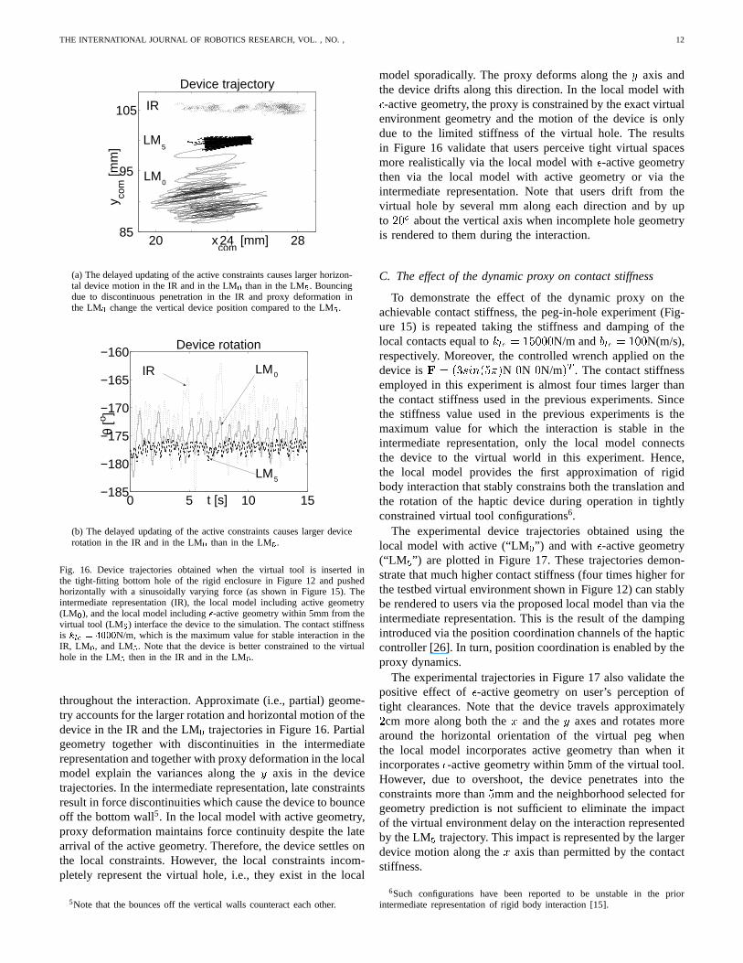
THE INTERNATIONAL JOURNAL OF ROBOTICS RESEARCH, VOL. , NO. , 12
20 24 2885
95
105
xcom
[mm]
y com
[mm
]
Device trajectory
IR
LM
LM
5
0
(a) The delayed updating of the active constraints causes larger horizon-tal device motion in the IR and in the LM0 than in the LM5. Bouncingdue to discontinuous penetration in the IR and proxy deformation inthe LM0 change the vertical device position compared to the LM5.
0 5 10 15−185
−180
−175
−170
−165
−160
t [s]
θ [o ]
Device rotation
IR LM
LM
0
5
(b) The delayed updating of the active constraints causes larger devicerotation in the IR and in the LM0 than in the LM5.
Fig. 16. Device trajectories obtained when the virtual toolis inserted inthe tight-fitting bottom hole of the rigid enclosure in Figure 12 and pushedhorizontally with a sinusoidally varying force (as shown inFigure 15). Theintermediate representation (IR), the local model including active geometry(LM0), and the local model including�-active geometry within 5mm from thevirtual tool (LM5) interface the device to the simulation. The contact stiffnessis klc = 4000N/m, which is the maximum value for stable interaction in theIR, LM0, and LM5. Note that the device is better constrained to the virtualhole in the LM5 then in the IR and in the LM0.
throughout the interaction. Approximate (i.e., partial) geome-try accounts for the larger rotation and horizontal motion of thedevice in the IR and the LM0 trajectories in Figure 16. Partialgeometry together with discontinuities in the intermediaterepresentation and together with proxy deformation in the localmodel explain the variances along they axis in the devicetrajectories. In the intermediate representation, late constraintsresult in force discontinuities which cause the device to bounceoff the bottom wall5. In the local model with active geometry,proxy deformation maintains force continuity despite the latearrival of the active geometry. Therefore, the device settles onthe local constraints. However, the local constraints incom-pletely represent the virtual hole, i.e., they exist in the local
5Note that the bounces off the vertical walls counteract eachother.
model sporadically. The proxy deforms along they axis andthe device drifts along this direction. In the local model with�-active geometry, the proxy is constrained by the exact virtualenvironment geometry and the motion of the device is onlydue to the limited stiffness of the virtual hole. The resultsin Figure 16 validate that users perceive tight virtual spacesmore realistically via the local model with�-active geometrythen via the local model with active geometry or via theintermediate representation. Note that users drift from thevirtual hole by several mm along each direction and by upto 20o about the vertical axis when incomplete hole geometryis rendered to them during the interaction.
C. The effect of the dynamic proxy on contact stiffness
To demonstrate the effect of the dynamic proxy on theachievable contact stiffness, the peg-in-hole experiment(Fig-ure 15) is repeated taking the stiffness and damping of thelocal contacts equal toklc = 15000N/m andblc = 100N(m/s),respectively. Moreover, the controlled wrench applied on thedevice isF = (3sin(5�)N 0N 0N/m)T . The contact stiffnessemployed in this experiment is almost four times larger thanthe contact stiffness used in the previous experiments. Sincethe stiffness value used in the previous experiments is themaximum value for which the interaction is stable in theintermediate representation, only the local model connectsthe device to the virtual world in this experiment. Hence,the local model provides the first approximation of rigidbody interaction that stably constrains both the translation andthe rotation of the haptic device during operation in tightlyconstrained virtual tool configurations6.
The experimental device trajectories obtained using thelocal model with active (“LM0”) and with �-active geometry(“LM 5”) are plotted in Figure 17. These trajectories demon-strate that much higher contact stiffness (four times higher forthe testbed virtual environment shown in Figure 12) can stablybe rendered to users via the proposed local model than via theintermediate representation. This is the result of the dampingintroduced via the position coordination channels of the hapticcontroller [26]. In turn, position coordination is enabledby theproxy dynamics.
The experimental trajectories in Figure 17 also validate thepositive effect of�-active geometry on user’s perception oftight clearances. Note that the device travels approximately2cm more along both thex and they axes and rotates morearound the horizontal orientation of the virtual peg whenthe local model incorporates active geometry than when itincorporates�-active geometry within5mm of the virtual tool.However, due to overshoot, the device penetrates into theconstraints more than5mm and the neighborhood selected forgeometry prediction is not sufficient to eliminate the impactof the virtual environment delay on the interaction representedby the LM5 trajectory. This impact is represented by the largerdevice motion along thex axis than permitted by the contactstiffness.
6Such configurations have been reported to be unstable in the priorintermediate representation of rigid body interaction [15].

THE INTERNATIONAL JOURNAL OF ROBOTICS RESEARCH, VOL. , NO. , 13
15 25 3580
85
90
95
100
xcom
[mm]
y com
[mm
]
Device trajectory
LM
LM
5
0
(a) Despite the large contact stiffness, the translation ofthe device isstable regardless of whether active or�-active geometry is used in thelocal model. Moreover,�-active geometry tighter constrains the positionof the device to the position of the virtual tool.
0 5 10 15−190
−180
−170
−160
−150
t [s]
θ [o ]
Device rotation
LM
LM
0
5
(b) Despite the large contact stiffness, the rotation of thedevice is stableregardless of whether active or�-active geometry is used in the localmodel. Moreover,�-active geometry tighter constrains the rotation ofthe device to the rotation of the virtual tool.
Fig. 17. Device trajectories obtained when the virtual toolis inserted in thetight-fitting bottom hole of the rigid enclosure in Figure 12and pushedhorizontally with a sinusoidally varying force (as depicted in Figure 15).The contact siffnessklc = 15000N/m is four times larger then in previousexperiments and the interaction is unstable in the intermediate representation.Only the local model with active geometry (LM0) and with�-active geometrywithin 5mm from the virtual tool (LM5) interface the device to the simulation.
VI. CONCLUSIONS
The local model of rigid body interaction proposed in thiswork comprises partial virtual environment geometry and anapproximate representation of the virtual tool dynamics calledthe dynamic proxy. The model selects the local geometryin a topology-independent manner. Therefore, it allows ahaptic device to be coupled to any simulation with interactiveperformance, regardless of the algorithms and of the datastructures used to generate the virtual world. At simulationupdates, the local model alleviates perceptual artifacts andavoids instability due to model discontinuities via proxy de-formation and via�-active geometry (i.e., virtual environmentgeometry within� distance from the virtual tool). Betweensimulation updates, the dynamic proxy allows physically-based virtual tool interactions to be computed locally regard-
less of whether users manipulate a virtual object or a virtuallinkage. A second advantage of the dynamic proxy is thatit enables the haptic controller to coordinate both wrenchesand body positions between the haptic device and the proxy.Hence, it facilitates the use of a controller that enhancesthe realism of the interaction compared both to the virtualcoupler [1], [2] and to the direct coupling approach [15].Compared to the virtual coupler, this controller enables usersto feel physical phenomena represented through fast forcetransitions, such as collisions and friction. Compared to directcoupling, the controller introduces additional damping viathe position coordination channels and, thus, allows stiffercontacts to be rendered to users. Experiments performed usinga planar virtual world interfaced to the haptic device throughthe proposed local model of interaction illustrate that usersmore realistically perceive tight virtual spaces and that theycan manipulate stiffer objects. These experiments also showthat, unlike the intermediate representation [15], the localmodel stably constrains both the translation and the rotation ofthe device. They report the first local approximation of rigidbody interaction that can fully interface a haptic device toamultibody simulation with interactive performance.
The proposed local model does not guarantee the stability ofthe interactions for arbitrary virtual environment geometries.Moreover, its performance degrades during fast user motions.Future work will focus on computing physically-motivatedforces that represent guaranteed limited stiffness and on en-hancing the local geometry based on predicting user motion.
REFERENCES
[1] J. Colgate, M. Stanley, and J. Brown, “Issues in the Haptic Display ofTool Use,” in Proc. IEEE/RSJ International Conference on IntelligentRobots and Systems, Pittsburgh, PA, 1995, pp. 140–145.
[2] R. Adams and B. Hannaford, “Stable Haptic Interaction with VirtualEnvironments,”IEEE Transactions on Robotics and Automation, vol. 15,no. 3, pp. 465–474, June 1999.
[3] C. Zilles and J. Salisbury, “A Constraint-based God Object Method forHaptic Display,” inProc. IEEE/RSJ International Conference on Intel-ligent Robots and Systems, Human Robot Interaction, and CooperativeRobots, Chicago, IL, 1995, pp. 146–151.
[4] J. Brown and J. Colgate, “Passive Implementation of Multibody Sim-ulations for Haptic Display,” inProc. ASME International MechanicalEngineering Congress and Exhibition, Dallas, TX, 1997, pp. 85–92.
[5] B. Chang and J. Colgate, “Real-Time Impulse-Based Simulation ofRigid Body Systems for Haptic Display,” inProc. ASME InternationalMechanical Engineering Congress and Exhibition, Dallas, Texas, 1997,pp. 1–8.
[6] D. Ruspini, K. Koralov, and O. Khatib, “The Haptic Display of ComplexGraphical Environments,” inProc. SIGGRAPH, Los Angeles, CA, 1997,pp. 345–352.
[7] A. Gregory, A. Mascarenhas, S. Ehmann, M. Lin, and D. Manocha, “SixDegree-of-Freedom Haptic Display of Polygonal Models,” inProc. IEEEVisualization, 2000, pp. 139–146.
[8] Y. Kim, M. Otaduy, M. Lin, and D. Manocha, “Six-Degree-ofFreedomHaptic Display Using Incremental and Localized Contact Computa-tions,” Presence: Teleoperators and Virtual Environments, vol. 12, no. 3,pp. 277–295, June 2003.
[9] D. Johnson and P. Willemsen, “Six Degree-of-Freedom Haptic Render-ing of Complex Polygonal Models,” inProc. 11th International Sym-posium on Haptic Interfaces for Virtual Environment and TeleoperatorSystems, Los Angeles, Ca, 2003, pp. 229–235.
[10] S. Vedula and D. Baraff, “Force feedback in interactivedynamicsimulation,” in Proc. First PHANTOM Users Group Workshop, 1996,pp. 54–57.
[11] Y. Adachi, T. Kumano, and K. Ogino, “Intermediate Representation forStiff Virtual Objects,” inProc. IEEE Virtual Reality Annual InternationalSymposium, Research Triangle Park, NC, 1995, pp. 203–210.

THE INTERNATIONAL JOURNAL OF ROBOTICS RESEARCH, VOL. , NO. , 14
[12] W. Mark, S. Randolph, M. Finch, J. Van Verth, and R. Taylor II, “AddingForce Feedback to Graphics Systems: Issues and Solutions,”in HapticVirtual Reality for Blind Computer Users, Assistive Technologies, 1998,pp. 92–99.
[13] C. Mendoza and C. Laugier, “Realistic Haptic Renderingfor HighlyDeformable Virtual Objects,” inProc IEEE Virtual Reality, 2001, pp.264–270.
[14] J. Park and G. Niemeyer, “Haptic Rendering with Predictive Repre-sentation of Local Geometry,” inProc. 12th Interantional Symposiumon Haptic Interfaces for Virtual Environment and Teleoperator Systems,Chicago, IL, 2004, pp. 331–338.
[15] P. Berkelman, R. Hollis, and D. Baraff, “Interaction with a RealtimeDynamic Environment Simulation using a Magnetic Levitation HapticInterface Device,” inProc. International Conference on Robotics andAutomation, Detroit, Michigan, 1999, pp. 3261–3266.
[16] J. Basch, J. Erickson, L. Guibas, J. Herschberger, and L. Zhang, “KineticCollision Detection between Two Simple Polygons,” inProc. 10th ACM-SIAM Symposium on Discrete Algorithms, 1999, pp. 102–111.
[17] J. Erickson, L. Guibas, J. Stolfi, and L. Zhang, “Separation SensitiveCollision Detection for Convex Objects,” inProc. 10th ACM-SIAMSymposium on Discrete Algorithms, 1999, pp. 327–336.
[18] D. Kirkpatrick, J. Snoeyink, and B. Speckman, “KineticCollisionDetection Simple Polygons,”International Journal of ComputationalGeometry and Applications, vol. 12, pp. 3–27, 2002.
[19] D. Corming and O. Staadt, “Velocity-Aligned Discrete Oriented Poly-topes for Dynamic Collision Detection,” University of California, Davis,CA, Tech. Rep. TCSE-2005-25, September 2004.
[20] J. Canny, “Collision Detection for Moving Polyhedra,”IEEE Transac-tions on Patern Analysis and Machine Intelligence, vol. 8, pp. 200–209,1986.
[21] S. Cameron, “Collision Detection by Four-DimensionalIntersectionTesting,” in Proc. IEEE International Conference on Robotics andAutomation, 1990, pp. 291–302.
[22] B. Herzen, A. Barr, and H. Zatz, “Geometric Collisions for TimeDependent Parametric Surfaces,”Computer Graphics, vol. 24, pp. 39–48, 1990.
[23] P. Hubbard, “Collision Detection for Interactive Graphics Applications,”IEEE Transactions on Visualization and Computer Graphics, vol. 1,no. 3, pp. 218–230, September 1995.
[24] D. Redon, A. Kheddar, and S. Coquillart, “An Algebraic Solution tothe Problem of Collision Detection for Rigid Polyhedral Objects,” inProc. IEEE International Conference on Robotics and Automation, SanFrancisco, CA, 2000.
[25] D. Ruspini, K. Koralov, and O. Khatib, “Haptic Interaction in VirtualEnvironments,” inProc. IEEE/RSJ International Conference on Intelli-gent Robots and Systems: IROS’97, Genoble, France, 1997.
[26] M. Sirouspour, S. DiMaio, S. Salcudean, P. Abolmaesumi, and C. Jones,“Haptic Interface Control – Design Issues and Experiments with aPlanar Device,” inProc. IEEE International Conference on Roboticsand Automation, San Francisco, Ca, 2000, pp. 789–794.
[27] J. Brown and J. Colgate, “Physics-based Approach to Haptic Display,”in Proc. Topical Workshop on Virtual Reality, International Symposiumon Measurement and Control in Robotics, vol. 1, Houston, TX, 1994,pp. 101–106.
[28] J. Canny,The Complexity of Robot Motion Planning. MIT Press,Cambridge, MA, 1987.
[29] D. Baraff, “Curved Surfaces and Coherence for Non-Penetrating RigidBody Simulation,”ACM Computer Graphics, vol. 24, no. 4, pp. 19–28,1990.
[30] ——, “Rigid body simulation,” inAn Introduction to Physically BasedModelling, Course Notes. ACM SIGGRAPH, 1995, pp. 1–68.
[31] E. Larsen, S. Gottschalk, M. Lin, and D. Manocha, “Fast ProximityQueries with Swept Sphere Volumes,” University of North Carolina,Chapel Hill, NC, Tech. Rep. TR99-018, 1999.
[32] J. Brown, “A Theoretical and Experimental Investigation into the FactorsAffecting the Z-width of a Haptic Display,” Master’s thesis, NothwesternUniversity, 1998.
[33] D. Constantinescu, S. Salcudean, and E. Croft, “HapticRendering ofRigid Contacts using Impulsive and Penalty Forces,”IEEE Transactionson Robotics, vol. 21, no. 3, pp. 309–323, June 2005.
[34] L. Rosenberg and B. Adelstein, “Perceptual Decomposition of VirtualHaptic Surfaces,” inProc. IEEE Symposium on Research Frontiers inVirtual Reality, San Jose, CA, 1993, pp. 46–53.
[35] D. Lawrence, L. Pao, A. Dougherty, M. Salada, and Y. Pavlou, “Rate-Hardness: A New Performance Metric for Haptic Interfaces,”IEEETransactions on Robotics and Automation, vol. 16, no. 4, pp. 357–371,2000.
[36] D. Ruspini and O. Khatib, “Dynamic Models for Haptic RenderingSystems,” inAdvances in Robot Kinematics: ARK98, Strobl/Salzburg,Austria, 1998, pp. 523–532.
[37] ——, “Haptic Display for Human Interaction with VirtualDynamicEnvironments,”Journal of Robotic Systems, vol. 18, no. 2, pp. 769–783, 2001.
[38] A. Nahvi, J. Hollerbach, R. Freier, and D. Nelson, “Display of Frictionin Virtual Environments based on Human Finger Pad Characteristics,”in Proc. ASME Dynamics Systems and Control Division, vol. DSC-64,1998, pp. 179–184.
[39] V. Hayward and B. Armstrong, “A new computational modelof frictionapplied to haptic rendering,” inExperimental Robotics VI. Lecture Notesin Control and Information Sciences, P. Corke and J. Trevelyan, Eds.Springer: New-York, 2000, vol. LNCS 250, pp. 404–412.
[40] O. Khatib, “Inertial Properties in Robotic Manipulation: An Object-Level Framework,”International Journal of Robotics Research, vol. 13,no. 1, pp. 19–36, 1995.
[41] J. Colgate, “Coupled Stability of Multiport Systems - Theory andExperiments,”Transactions of the ASME, Journal of Dynamic Systems,Measurement, and Control, vol. 116, no. 3, pp. 419–428, 1994.
[42] B. Hannaford and R. Anderson, “Experimental and Simulation Studiesof Hard Contact Force Reflecting Teleoperation,” inProc. IEEE Inter-national Conference on Robotics and Automation, Scottsdale, AZ, May1988, pp. 24–29.
[43] D. Constantinescu, S. Salcudean, and E. Croft, “Impulsive Forcesfor Haptic Rendering of Rigid Contacts,” inProc. 35th InternationalSymposium on Robotics, Paris, France, 2004, pp. 1–6.
Related Documents