Load Path Effects in Circular Steel Columns under Bidirectional Lateral Cyclic Loading Alper Ucak, A.M.ASCE 1 ; and Panos Tsopelas, A.M.ASCE 2 Abstract: Rigorous numerical analyses are conducted to study the effects of bidirectional lateral cyclic loading on the hysteretic response of stocky circular thin-walled steel columns. Four unidirectional and eight bidirectional lateral displacement controlled load paths are considered; different performance indices obtained from the lateral load paths under consideration are compared. The results obtained from these comprehensive numerical analyses indicate that bidirectional lateral cyclic loading has a very limited effect on the ultimate strength of stocky circular thin-walled steel columns, but significantly decreases the ductility when compared with unidirectional lateral loading. DOI: 10.1061/(ASCE)ST.1943-541X.0001057. © 2014 American Society of Civil Engineers. Author keywords: Cyclic loading; Bidirectional loading; Load path effects; Steel columns; Buckling; Seismic effects. Introduction Thin-walled steel tubular columns/piers, with either circular or rectangular cross sections, are widely used as part of the lateral and vertical force resisting systems in buildings, offshore platforms, elevated storage tanks, and transmission towers, or as cantilever piers in bridges and in wind turbines. Thin-walled tubular steel sections may be preferred over their reinforced concrete counter- parts because of their high stiffness to cross-sectional area ratio. However, the performance of these members during the 1985 Mexico City and 1995 Hyogo-ken-Nanbu (Kobe) earthquakes, and the recent 2005 Katrina and Rita hurricanes (in the U.S.) have shown that these components are vulnerable to local buckling when subjected to cyclic lateral loading [Bruneau et al. 1996; Minerals Management Service (MMS) 2007]. The local buckling phenomenon in thin-walled circular steel sections under monotonic and unidirectional lateral cyclic loading has been the subject of numerous experimental and analytical studies. Ostapenko and Gunzelman (1976), Marzullo and Ostapenko (1977), Ostapenko and Grimm (1980), Stephens et al. (1982), and Bailey and Kulak (1984) conducted large-scale experi- ments to study the buckling of large-scale cylindrical tubes under axial compression. Hashimoto et al. (1996), Mizutani et al. (1996), and Nishikawa et al. (1998) tested many large diameter tubes as cantilever columns under constant axial load and alternating unidirectional lateral load. Usami and Ge (1998) performed a parametric finite-element study to determine the strength and deformation capacities of pipe section bridge piers under constant axial load and quasi-dynamic cyclic unidirectional lateral loading. Ucak and Tsopelas (2006) conducted a parametric finite-element study to investigate the efficiency of different seismic retrofit schemes for circular cross-sectioned cantilever columns. Although the response characteristics of thin-walled steel col- umns under monotonic and unidirectional lateral cyclic loading are well understood, seismic excitations are not unidirectional but bidirectional in nature. Studies conducted on RC columns (Saatcioglu and Ozcebe 1989; Wong et al. 1993; Bousias et al. 1995; Qiu et al. 2002), among others, showed a reduction in component performance when subjected to bidirectional lateral cyclic loading, owing to strong elastoplastic and damage coupling between the orthogonal directions. In contrast, only few studies have aimed to investigate the performance of steel columns under bidirectional lateral cyclic loading. The first study to investigate the performance of steel columns under bidirectional lateral cyclic loading was conducted by Watanabe et al. (2000) on small-scale unstiffened rectangular cross sections. Watanabe et al. (2000) concluded that bidirectional lateral cyclic loading decreased the lateral strength and deformation capacities of rectangular unstiffened steel columns when compared with unidirectional lateral cyclic loading. Goto et al. (2006, 2008) and Ucak and Tsopelas (2008) inde- pendently conducted finite-element analyses to investigate the lat- eral strength and deformation capacities of stocky cantilevered circular steel columns subjected to constant axial load and circular shaped out-of-phase (nonproportional) lateral displacement paths. The terms “out-of-phase” or “nonproportional displacement path” indicate a path in which the ratio between the increments of x and y components of the displacement (Δu x =Δu y ) will not remain con- stant (i.e., they change value, sign, or both) throughout the path. Goto et al. (2006) and Ucak and Tsopelas (2008) concluded that the lateral deformation capacity (or ductility) of thin-walled circular cantilevered columns decreased under a circular shape deformation path, compared with a unidirectional lateral cyclic load path of the same amplitude. Regarding lateral strength, Goto et al. (2006) used individual skeleton curves along the two orthogonal directions to define the lateral strength and reported a decrease in the lateral force capacity of the column under out-of-phase circular deforma- tion trajectories. Ucak and Tsopelas (2008) compared the maximum resultant lateral restoring force determined from the cir- cular load path with that determined from the unidirectional lateral load path, and reported that the ultimate strength (resultant restor- ing force) attained for these two paths were comparable, with no significant lateral force capacity decrease between them. Goto et al. (2009), using a set of seven recorded bidirectional seismic waves, 1 Postdoctoral Research Assistant, Dept. of Civil Engineering, Catholic Univ. of America, Washington, DC 20064. E-mail: 48ucak@cardinalmail .cua.edu 2 Associate Professor, Dept. of Civil Engineering, Univ. of Thessaly, Volos 38334, Greece (corresponding author). E-mail: [email protected] Note. This manuscript was submitted on March 12, 2013; approved on February 21, 2014; published online on July 17, 2014. Discussion period open until December 17, 2014; separate discussions must be submitted for individual papers. This paper is part of the Journal of Structural Engineer- ing, © ASCE, ISSN 0733-9445/04014133(11)/$25.00. © ASCE 04014133-1 J. Struct. Eng. J. Struct. Eng. Downloaded from ascelibrary.org by UNIVERSITY OF THESSALY on 09/29/14. Copyright ASCE. For personal use only; all rights reserved.

Welcome message from author
This document is posted to help you gain knowledge. Please leave a comment to let me know what you think about it! Share it to your friends and learn new things together.
Transcript
Load Path Effects in Circular Steel Columns underBidirectional Lateral Cyclic LoadingAlper Ucak, A.M.ASCE1; and Panos Tsopelas, A.M.ASCE2
Abstract: Rigorous numerical analyses are conducted to study the effects of bidirectional lateral cyclic loading on the hysteretic responseof stocky circular thin-walled steel columns. Four unidirectional and eight bidirectional lateral displacement controlled load paths areconsidered; different performance indices obtained from the lateral load paths under consideration are compared. The results obtained fromthese comprehensive numerical analyses indicate that bidirectional lateral cyclic loading has a very limited effect on the ultimate strength ofstocky circular thin-walled steel columns, but significantly decreases the ductility when compared with unidirectional lateral loading. DOI:10.1061/(ASCE)ST.1943-541X.0001057. © 2014 American Society of Civil Engineers.
Author keywords: Cyclic loading; Bidirectional loading; Load path effects; Steel columns; Buckling; Seismic effects.
Introduction
Thin-walled steel tubular columns/piers, with either circular orrectangular cross sections, are widely used as part of the lateraland vertical force resisting systems in buildings, offshore platforms,elevated storage tanks, and transmission towers, or as cantileverpiers in bridges and in wind turbines. Thin-walled tubular steelsections may be preferred over their reinforced concrete counter-parts because of their high stiffness to cross-sectional area ratio.However, the performance of these members during the 1985Mexico City and 1995 Hyogo-ken-Nanbu (Kobe) earthquakes,and the recent 2005 Katrina and Rita hurricanes (in the U.S.) haveshown that these components are vulnerable to local buckling whensubjected to cyclic lateral loading [Bruneau et al. 1996; MineralsManagement Service (MMS) 2007].
The local buckling phenomenon in thin-walled circular steelsections under monotonic and unidirectional lateral cyclic loadinghas been the subject of numerous experimental and analyticalstudies. Ostapenko and Gunzelman (1976), Marzullo andOstapenko (1977), Ostapenko and Grimm (1980), Stephens et al.(1982), and Bailey and Kulak (1984) conducted large-scale experi-ments to study the buckling of large-scale cylindrical tubes underaxial compression. Hashimoto et al. (1996), Mizutani et al. (1996),and Nishikawa et al. (1998) tested many large diameter tubes ascantilever columns under constant axial load and alternatingunidirectional lateral load. Usami and Ge (1998) performed aparametric finite-element study to determine the strength anddeformation capacities of pipe section bridge piers under constantaxial load and quasi-dynamic cyclic unidirectional lateral loading.Ucak and Tsopelas (2006) conducted a parametric finite-elementstudy to investigate the efficiency of different seismic retrofitschemes for circular cross-sectioned cantilever columns.
Although the response characteristics of thin-walled steel col-umns under monotonic and unidirectional lateral cyclic loadingare well understood, seismic excitations are not unidirectionalbut bidirectional in nature. Studies conducted on RC columns(Saatcioglu and Ozcebe 1989; Wong et al. 1993; Bousias et al.1995; Qiu et al. 2002), among others, showed a reduction incomponent performance when subjected to bidirectional lateralcyclic loading, owing to strong elastoplastic and damage couplingbetween the orthogonal directions. In contrast, only few studieshave aimed to investigate the performance of steel columns underbidirectional lateral cyclic loading.
The first study to investigate the performance of steel columnsunder bidirectional lateral cyclic loading was conducted byWatanabe et al. (2000) on small-scale unstiffened rectangular crosssections. Watanabe et al. (2000) concluded that bidirectional lateralcyclic loading decreased the lateral strength and deformationcapacities of rectangular unstiffened steel columns when comparedwith unidirectional lateral cyclic loading.
Goto et al. (2006, 2008) and Ucak and Tsopelas (2008) inde-pendently conducted finite-element analyses to investigate the lat-eral strength and deformation capacities of stocky cantileveredcircular steel columns subjected to constant axial load and circularshaped out-of-phase (nonproportional) lateral displacement paths.The terms “out-of-phase” or “nonproportional displacement path”indicate a path in which the ratio between the increments of x and ycomponents of the displacement (Δux=Δuy) will not remain con-stant (i.e., they change value, sign, or both) throughout the path.Goto et al. (2006) and Ucak and Tsopelas (2008) concluded thatthe lateral deformation capacity (or ductility) of thin-walled circularcantilevered columns decreased under a circular shape deformationpath, compared with a unidirectional lateral cyclic load path of thesame amplitude. Regarding lateral strength, Goto et al. (2006) usedindividual skeleton curves along the two orthogonal directions todefine the lateral strength and reported a decrease in the lateralforce capacity of the column under out-of-phase circular deforma-tion trajectories. Ucak and Tsopelas (2008) compared themaximum resultant lateral restoring force determined from the cir-cular load path with that determined from the unidirectional lateralload path, and reported that the ultimate strength (resultant restor-ing force) attained for these two paths were comparable, with nosignificant lateral force capacity decrease between them. Goto et al.(2009), using a set of seven recorded bidirectional seismic waves,
1Postdoctoral Research Assistant, Dept. of Civil Engineering, CatholicUniv. of America, Washington, DC 20064. E-mail: [email protected]
2Associate Professor, Dept. of Civil Engineering, Univ. of Thessaly,Volos 38334, Greece (corresponding author). E-mail: [email protected]
Note. This manuscript was submitted on March 12, 2013; approved onFebruary 21, 2014; published online on July 17, 2014. Discussion periodopen until December 17, 2014; separate discussions must be submitted forindividual papers. This paper is part of the Journal of Structural Engineer-ing, © ASCE, ISSN 0733-9445/04014133(11)/$25.00.
© ASCE 04014133-1 J. Struct. Eng.
J. Struct. Eng.
Dow
nloa
ded
from
asc
elib
rary
.org
by
UN
IVE
RSI
TY
OF
TH
ESS
AL
Y o
n 09
/29/
14. C
opyr
ight
ASC
E. F
or p
erso
nal u
se o
nly;
all
righ
ts r
eser
ved.
tested the hypothesis of predicting the ultimate state for thin-walledcircular steel columns in terms of horizontal restoring force(strength capacity) by using the strength of the unidirectional lateralpush over loading path. They concluded that the ultimate state interms of horizontal restoring force is accurately predicted by thestrength of the unidirectional lateral push over the loading path,a conclusion that supports the one reached by Ucak and Tsopelas(2008). Although the results presented in the study of Goto et al.(2009) are informative regarding when a given system reaches itsultimate state under a given earthquake motion, they may not havegeneral applicability about how the bidirectional loading pathsaffect the performance of the system. As an example, one mayconsider a single pulse-shaped bidirectional near field earthquakeexcitation, under which a given system may not take advantage ofthe cyclic hardening characteristics of the base material. Thesystem may display a response close to monotonic loading andmay fail. However, this failure cannot be attributed to bidirectionalloading; it is likely because the system did not have enoughductility to resist the applied demands.
This paper investigates the effects of bidirectional out-of-phaselateral cyclic loading (displacement) paths on the hystereticresponse of stocky circular thin-walled steel columns, using arigorous finite-element model that can account for the nonlinearbehavior of the base material. The displacement controlled loadingpaths studied are different from those considered by Goto et al.(2006) and Ucak and Tsopelas (2008). Four unidirectional andeight out-of-phase bidirectional lateral displacement controlledloading paths are utilized. These broadly varying loading pathswere selected to represent most loading paths that might appearwhen a random load (e.g., earthquake excitation) is experiencedby the system. Recorded seismic paths from particular seismicexcitations may be used instead of artificial complex loading paths,as is the case in this study. However, individual seismic loadingpaths are limited by the properties and specific details of theparticular seismic excitation in use, which does not warrant wide
applicability or clear understanding about how a system performsunder any complex loading path.
The analysis results from the current study are presented interms of hysteresis curves, lateral force trajectories, and energyabsorption capacities to facilitate a meaningful comparisonbetween the performance parameters determined under unidirec-tional and bidirectional lateral loading histories. The results pre-sented in this study are expected to provide important insightsinto the performance of stocky circular thin-walled steel membersused as part of the lateral force resisting system in earthquakeprone areas.
Simulation Model
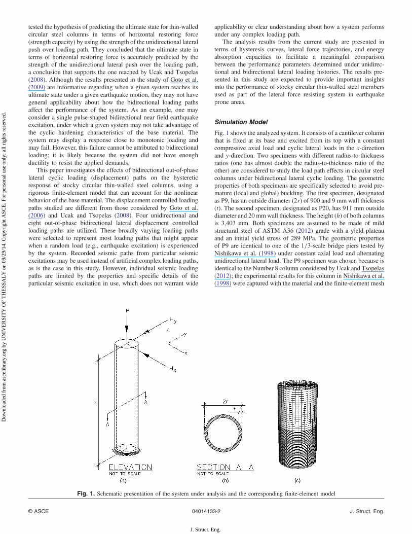
Fig. 1 shows the analyzed system. It consists of a cantilever columnthat is fixed at its base and excited from its top with a constantcompressive axial load and cyclic lateral loads in the x-directionand y-direction. Two specimens with different radius-to-thicknessratios (one has almost double the radius-to-thickness ratio of theother) are considered to study the load path effects in circular steelcolumns under bidirectional lateral cyclic loading. The geometricproperties of both specimens are specifically selected to avoid pre-mature (local and global) buckling. The first specimen, designatedas P9, has an outside diameter (2r) of 900 and 9 mm wall thickness(t). The second specimen, designated as P20, has 911 mm outsidediameter and 20 mmwall thickness. The height (h) of both columnsis 3,403 mm. Both specimens are assumed to be made of mildstructural steel of ASTM A36 (2012) grade with a yield plateauand an initial yield stress of 289 MPa. The geometric propertiesof P9 are identical to one of the 1=3-scale bridge piers tested byNishikawa et al. (1998) under constant axial load and alternatingunidirectional lateral load. The P9 specimen was chosen because isidentical to the Number 8 column considered by Ucak and Tsopelas(2012); the experimental results for this column in Nishikawa et al.(1998) were captured with the material and the finite-element mesh
Fig. 1. Schematic presentation of the system under analysis and the corresponding finite-element model
© ASCE 04014133-2 J. Struct. Eng.
J. Struct. Eng.
Dow
nloa
ded
from
asc
elib
rary
.org
by
UN
IVE
RSI
TY
OF
TH
ESS
AL
Y o
n 09
/29/
14. C
opyr
ight
ASC
E. F
or p
erso
nal u
se o
nly;
all
righ
ts r
eser
ved.
used in the current study. This adds confidence to the results ofthis study. Specimen P20 was designed to represent a rather stockycolumn with high ductility.
The finite-element analyses were conducted by using thecommercially available finite-element software ABAQUS. Thefinite-element model used in the study is also depicted in Fig. 1.The model consists of general purpose conventional shell elements,beam elements, and rigid links, all of which are available in theABAQUS element library; the model is identical to that utilizedand verified by Ucak and Tsopelas (2012). The lower part ofthe column, where the localized deformation is concentrated(Nishikawa et al. 1998), is discretized with shell elements, whereasthe rest is modeled by using beam elements. Beam elements areconnected to shell elements by using rigid links. For computationalefficiency, a variable mesh density (Fig. 1) is used in the analyses,such that the density of the mesh at the lower section of the column,where local buckling is expected, is denser than the remaining part.Using a trial-and-error approach, the density of the mesh wasdetermined when no significant improvement in the results wasreached after two successive discretizations. The same meshdensity is utilized for both columns (P9 and P20). Forty elementsare used in the circumferential direction. In the vertical directionand within a diameter from the base, the column is divided into60 segments. The boundary conditions at the base were assumedto be fixed. In the present analyses, the effects of initial residualstresses induced by welding and initial imperfections of the columnwalls were neglected. This assumption was motivated by the natureof the load paths under consideration. Parametric numericalanalyses conducted by Banno et al. (1998) suggest that these effectswill accelerate some buckling modes under monotonic loading, buthave limited effect on the overall hysteretic response of platedstructures under reversed (cyclic) loading.
A time-independent constitutive model for structural steels witha yield plateau, developed by Ucak and Tsopelas (2011), is utilizedin the column models in this study. The model is based on the basicprinciples of time-independent plasticity, coupling the nonlinearkinematic hardening concept with a memory surface in the plasticstrain space and a pseudo-memory surface in the deviatoric stressspace. A detailed description of the constitutive model, whichis capable of capturing the material responses for monotonic,proportional, and nonproportional cyclic loading paths, togetherwith comparisons against experimental data, is presented by Ucakand Tsopelas (2011).
The performance of the constitutive model was verified at thestructural component level by means of finite-element simulationsof large-scale structural columns or bridge piers, against experi-mental data from the literature (Nishikawa et al. 1998, Nakamuraet al. 1997; Fukumoto 2004) under constant axial load and unidi-rectional quasi-static cyclic loading. The comparisons of the struc-tural columns between the finite-element models and theexperimental results and calibrated values of the model parametersare given by Ucak and Tsopelas (2012).
Loading Protocols
Load path effects in circular steel columns were investigated byusing 12 quasi-static cyclic lateral loading protocols: four unidirec-tional and eight out-of-phase bidirectional. For all lateral loadingprotocols under consideration, the axial load of the column waskept constant at 12.5% of the axial yield load throughout the load-ing history. This normalized axial load value is approximately equalto the average normalized design axial load in existing steel bridgepiers (Nishikawa et al. 1998). The axial yield load (Po) is defined asPo ¼ A × Fy, where A is the cross-sectional area of the specimen
and Fy is the yield stress of the base material. The specimens areexcited laterally in displacement controlled mode, with increasingamplitudes as multiples of the lateral yield displacement. The lat-eral yield displacement (do) is defined as do ¼ Hoh3=ðEIÞ, whereE is the Young’s modulus, I is the moment of inertia of the crosssection, and Ho is the lateral yield load. The lateral yield load isdefined as Ho ¼ ðFy − P=AÞI=ðrhÞ, where P is the applied axialload. The values of the lateral yield displacement, lateral yield load,and the applied axial load for both specimens are reported inTable 1.
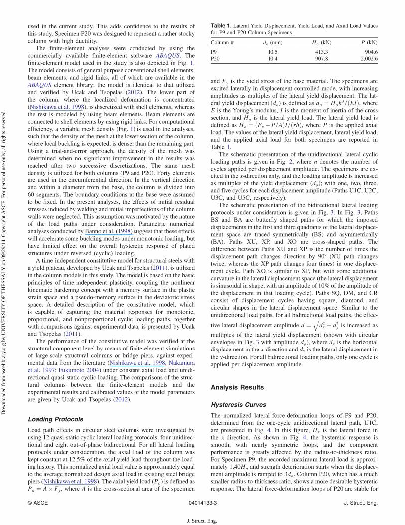
The schematic presentation of the unidirectional lateral cyclicloading paths is given in Fig. 2, where n denotes the number ofcycles applied per displacement amplitude. The specimens are ex-cited in the x-direction only, and the loading amplitude is increasedas multiples of the yield displacement (do); with one, two, three,and five cycles for each displacement amplitude (Paths U1C, U2C,U3C, and U5C, respectively).
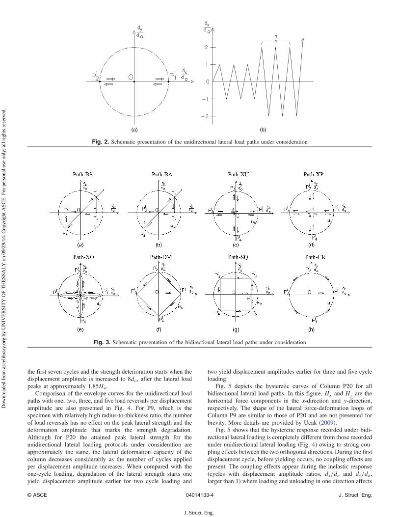
The schematic presentation of the bidirectional lateral loadingprotocols under consideration is given in Fig. 3. In Fig. 3, PathsBS and BA are butterfly shaped paths for which the imposeddisplacements in the first and third quadrants of the lateral displace-ment space are traced symmetrically (BS) and asymmetrically(BA). Paths XU, XP, and XO are cross-shaped paths. Thedifference between Paths XU and XP is the number of times thedisplacement path changes direction by 90° (XU path changestwice, whereas the XP path changes four times) in one displace-ment cycle. Path XO is similar to XP, but with some additionalcurvature in the lateral displacement space (the lateral displacementis sinusoidal in shape, with an amplitude of 10% of the amplitude ofthe displacement in that loading cycle). Paths SQ, DM, and CRconsist of displacement cycles having square, diamond, andcircular shapes in the lateral displacement space. Similar to theunidirectional load paths, for all bidirectional load paths, the effec-
tive lateral displacement amplitude d ¼ffiffiffiffiffiffiffiffiffiffiffiffiffiffiffid2x þ d2y
qis increased as
multiples of the lateral yield displacement (shown with circularenvelopes in Fig. 3 with amplitude do), where dx is the horizontaldisplacement in the x-direction and dy is the lateral displacement inthe y-direction. For all bidirectional loading paths, only one cycle isapplied per displacement amplitude.
Analysis Results
Hysteresis Curves
The normalized lateral force-deformation loops of P9 and P20,determined from the one-cycle unidirectional lateral path, U1C,are presented in Fig. 4. In this figure, Hx is the lateral force inthe x-direction. As shown in Fig. 4, the hysteretic response issmooth, with nearly symmetric loops, and the componentperformance is greatly affected by the radius-to-thickness ratio.For Specimen P9, the recorded maximum lateral load is approxi-mately 1.40Ho and strength deterioration starts when the displace-ment amplitude is ramped to 3do. Column P20, which has a muchsmaller radius-to-thickness ratio, shows a more desirable hystereticresponse. The lateral force-deformation loops of P20 are stable for
Table 1. Lateral Yield Displacement, Yield Load, and Axial Load Valuesfor P9 and P20 Column Specimens
Column # do (mm) Ho (kN) P (kN)
P9 10.5 413.3 904.6P20 10.4 907.8 2,002.6
© ASCE 04014133-3 J. Struct. Eng.
J. Struct. Eng.
Dow
nloa
ded
from
asc
elib
rary
.org
by
UN
IVE
RSI
TY
OF
TH
ESS
AL
Y o
n 09
/29/
14. C
opyr
ight
ASC
E. F
or p
erso
nal u
se o
nly;
all
righ
ts r
eser
ved.
the first seven cycles and the strength deterioration starts when thedisplacement amplitude is increased to 8do, after the lateral loadpeaks at approximately 1.85Ho.
Comparison of the envelope curves for the unidirectional loadpaths with one, two, three, and five load reversals per displacementamplitude are also presented in Fig. 4. For P9, which is thespecimen with relatively high radius-to-thickness ratio, the numberof load reversals has no effect on the peak lateral strength and thedeformation amplitude that marks the strength degradation.Although for P20 the attained peak lateral strength for theunidirectional lateral loading protocols under consideration areapproximately the same, the lateral deformation capacity of thecolumn decreases considerably as the number of cycles appliedper displacement amplitude increases. When compared with theone-cycle loading, degradation of the lateral strength starts oneyield displacement amplitude earlier for two cycle loading and
two yield displacement amplitudes earlier for three and five cycleloading.
Fig. 5 depicts the hysteretic curves of Column P20 for allbidirectional lateral load paths. In this figure, Hx and Hy are thehorizontal force components in the x-direction and y-direction,respectively. The shape of the lateral force-deformation loops ofColumn P9 are similar to those of P20 and are not presented forbrevity. More details are provided by Ucak (2009).
Fig. 5 shows that the hysteretic response recorded under bidi-rectional lateral loading is completely different from those recordedunder unidirectional lateral loading (Fig. 4) owing to strong cou-pling effects between the two orthogonal directions. During the firstdisplacement cycle, before yielding occurs, no coupling effects arepresent. The coupling effects appear during the inelastic response(cycles with displacement amplitude ratios, dx=do and dy=do,larger than 1) where loading and unloading in one direction affects
(a) (b)
Fig. 2. Schematic presentation of the unidirectional lateral load paths under consideration
Fig. 3. Schematic presentation of the bidirectional lateral load paths under consideration
© ASCE 04014133-4 J. Struct. Eng.
J. Struct. Eng.
Dow
nloa
ded
from
asc
elib
rary
.org
by
UN
IVE
RSI
TY
OF
TH
ESS
AL
Y o
n 09
/29/
14. C
opyr
ight
ASC
E. F
or p
erso
nal u
se o
nly;
all
righ
ts r
eser
ved.
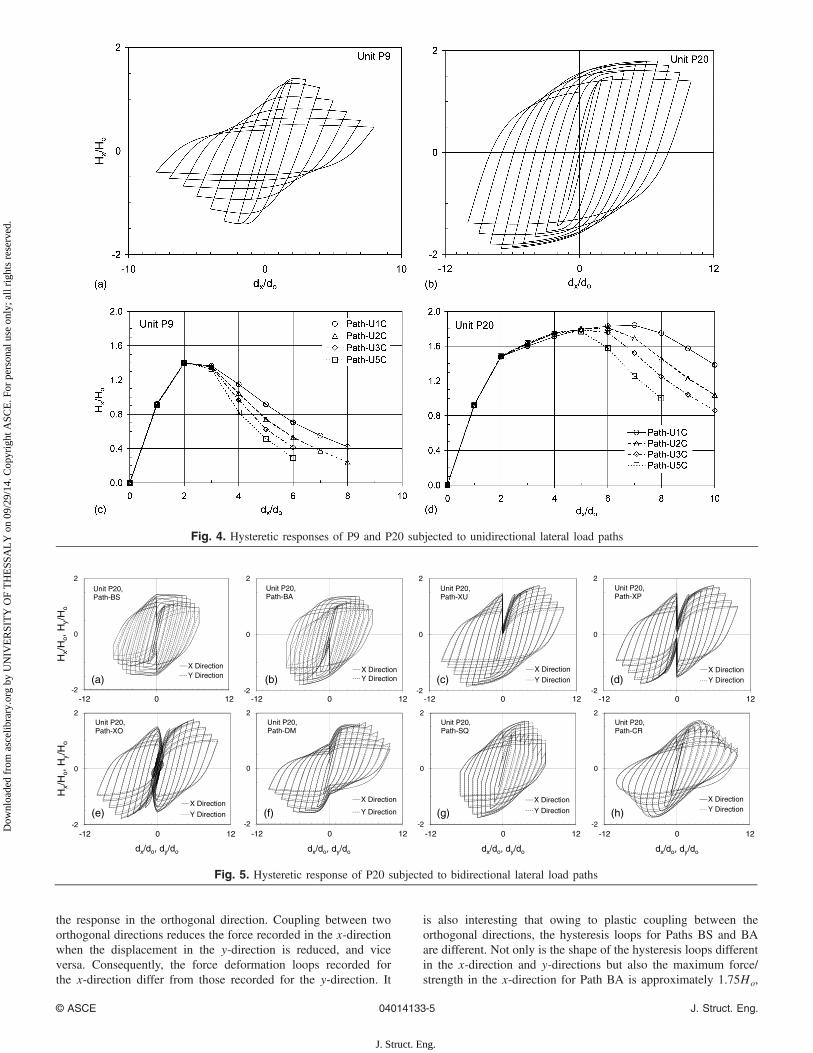
the response in the orthogonal direction. Coupling between twoorthogonal directions reduces the force recorded in the x-directionwhen the displacement in the y-direction is reduced, and viceversa. Consequently, the force deformation loops recorded forthe x-direction differ from those recorded for the y-direction. It
is also interesting that owing to plastic coupling between theorthogonal directions, the hysteresis loops for Paths BS and BAare different. Not only is the shape of the hysteresis loops differentin the x-direction and y-directions but also the maximum force/strength in the x-direction for Path BA is approximately 1.75Ho,
Fig. 4. Hysteretic responses of P9 and P20 subjected to unidirectional lateral load paths
-2
0
2
Hx/
Ho,
Hy/
Ho
X DirectionY Direction
Unit P20, Path-BS
(a)-2
0
2
X DirectionY Direction
Unit P20, Path-BA
(b)-2
0
2
X DirectionY Direction
Unit P20, Path-XU
(c)-2
0
2
-12 0 12 -12 0 12 -12 0 12 -12 0 12
X DirectionY Direction
Unit P20, Path-XP
(d)
-2
0
2
Hx/
Ho,
Hy/
Ho
dx/do, dy/do
X Direction
Y Direction
Unit P20, Path-XO
(e)-2
0
2
dx/do, dy/do
X Direction
Y Direction
Unit P20, Path-DM
(f)-2
0
2
dx/do, dy/do
X Direction
Y Direction
Unit P20, Path-SQ
(g)-2
0
2
-12 0 12 -12 0 12 -12 0 12 -12 0 12
dx/do, dy/do
X DirectionY Direction
Unit P20, Path-CR
(h)
Fig. 5. Hysteretic response of P20 subjected to bidirectional lateral load paths
© ASCE 04014133-5 J. Struct. Eng.
J. Struct. Eng.
Dow
nloa
ded
from
asc
elib
rary
.org
by
UN
IVE
RSI
TY
OF
TH
ESS
AL
Y o
n 09
/29/
14. C
opyr
ight
ASC
E. F
or p
erso
nal u
se o
nly;
all
righ
ts r
eser
ved.
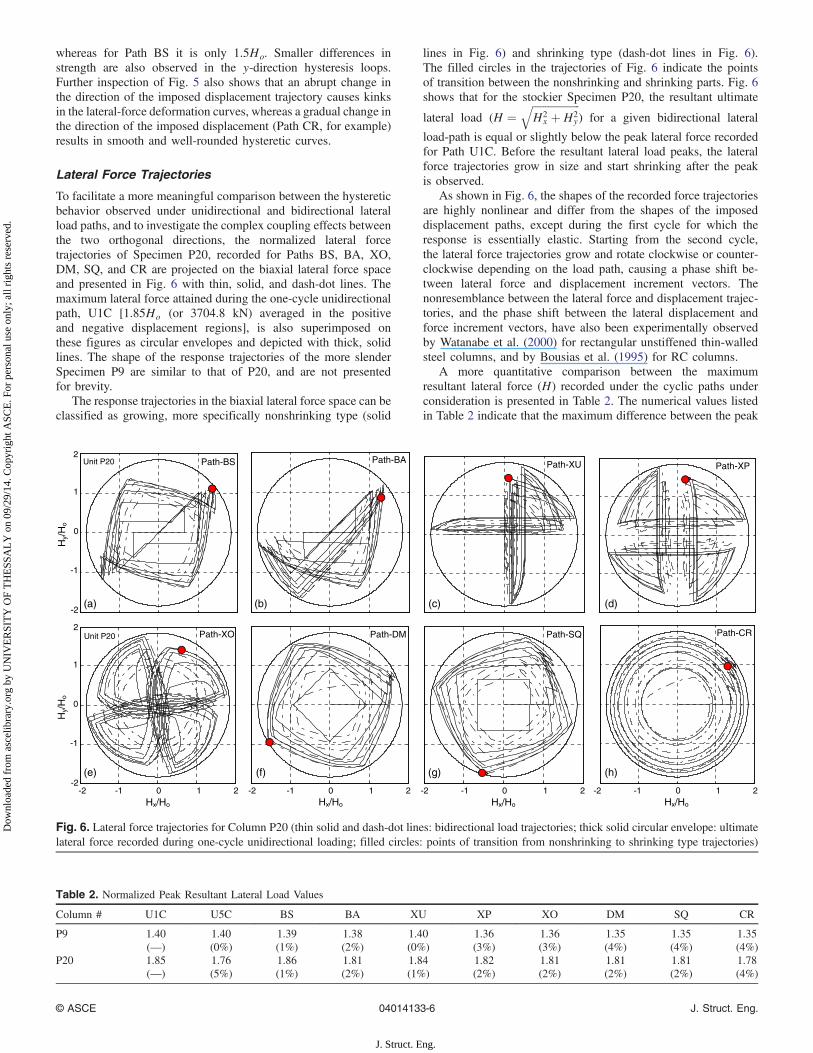
whereas for Path BS it is only 1.5Ho. Smaller differences instrength are also observed in the y-direction hysteresis loops.Further inspection of Fig. 5 also shows that an abrupt change inthe direction of the imposed displacement trajectory causes kinksin the lateral-force deformation curves, whereas a gradual change inthe direction of the imposed displacement (Path CR, for example)results in smooth and well-rounded hysteretic curves.
Lateral Force Trajectories
To facilitate a more meaningful comparison between the hystereticbehavior observed under unidirectional and bidirectional lateralload paths, and to investigate the complex coupling effects betweenthe two orthogonal directions, the normalized lateral forcetrajectories of Specimen P20, recorded for Paths BS, BA, XO,DM, SQ, and CR are projected on the biaxial lateral force spaceand presented in Fig. 6 with thin, solid, and dash-dot lines. Themaximum lateral force attained during the one-cycle unidirectionalpath, U1C [1.85Ho (or 3704.8 kN) averaged in the positiveand negative displacement regions], is also superimposed onthese figures as circular envelopes and depicted with thick, solidlines. The shape of the response trajectories of the more slenderSpecimen P9 are similar to that of P20, and are not presentedfor brevity.
The response trajectories in the biaxial lateral force space can beclassified as growing, more specifically nonshrinking type (solid
lines in Fig. 6) and shrinking type (dash-dot lines in Fig. 6).The filled circles in the trajectories of Fig. 6 indicate the pointsof transition between the nonshrinking and shrinking parts. Fig. 6shows that for the stockier Specimen P20, the resultant ultimate
lateral load (H ¼ffiffiffiffiffiffiffiffiffiffiffiffiffiffiffiffiffiffiH2
x þH2y
q) for a given bidirectional lateral
load-path is equal or slightly below the peak lateral force recordedfor Path U1C. Before the resultant lateral load peaks, the lateralforce trajectories grow in size and start shrinking after the peakis observed.
As shown in Fig. 6, the shapes of the recorded force trajectoriesare highly nonlinear and differ from the shapes of the imposeddisplacement paths, except during the first cycle for which theresponse is essentially elastic. Starting from the second cycle,the lateral force trajectories grow and rotate clockwise or counter-clockwise depending on the load path, causing a phase shift be-tween lateral force and displacement increment vectors. Thenonresemblance between the lateral force and displacement trajec-tories, and the phase shift between the lateral displacement andforce increment vectors, have also been experimentally observedby Watanabe et al. (2000) for rectangular unstiffened thin-walledsteel columns, and by Bousias et al. (1995) for RC columns.
A more quantitative comparison between the maximumresultant lateral force (H) recorded under the cyclic paths underconsideration is presented in Table 2. The numerical values listedin Table 2 indicate that the maximum difference between the peak
0 0 0 0
Path-BS Unit P20 Path-BAPath-XPPath-XU
Path-SQ Path-CRPath-DM
Hx/Ho
Unit P20
Hx/HoHx/HoHx/Ho
-2-2
-1
1
2
0
Hy/
Ho
-2(a) (b) (c) (d)
(e) (f) (g) (h)
-1
1
2
0
Hy/
Ho
-2-1 -1 1 2 1 2 -2 -1 1 2 -2 -1 1 2
Path-XO
Fig. 6. Lateral force trajectories for Column P20 (thin solid and dash-dot lines: bidirectional load trajectories; thick solid circular envelope: ultimatelateral force recorded during one-cycle unidirectional loading; filled circles: points of transition from nonshrinking to shrinking type trajectories)
Table 2. Normalized Peak Resultant Lateral Load Values
Column # U1C U5C BS BA XU XP XO DM SQ CR
P9 1.40 1.40 1.39 1.38 1.40 1.36 1.36 1.35 1.35 1.35(—) (0%) (1%) (2%) (0%) (3%) (3%) (4%) (4%) (4%)
P20 1.85 1.76 1.86 1.81 1.84 1.82 1.81 1.81 1.81 1.78(—) (5%) (1%) (2%) (1%) (2%) (2%) (2%) (2%) (4%)
© ASCE 04014133-6 J. Struct. Eng.
J. Struct. Eng.
Dow
nloa
ded
from
asc
elib
rary
.org
by
UN
IVE
RSI
TY
OF
TH
ESS
AL
Y o
n 09
/29/
14. C
opyr
ight
ASC
E. F
or p
erso
nal u
se o
nly;
all
righ
ts r
eser
ved.
lateral force attained for the one-cycle unidirectional path (U1C)and the bidirectional paths is less than 5%. Also, for the stockierSpecimen P20, this difference approximately equals that betweenthe one-cycle and five-cycle unidirectional lateral loading.
Energy Absorption Capacity
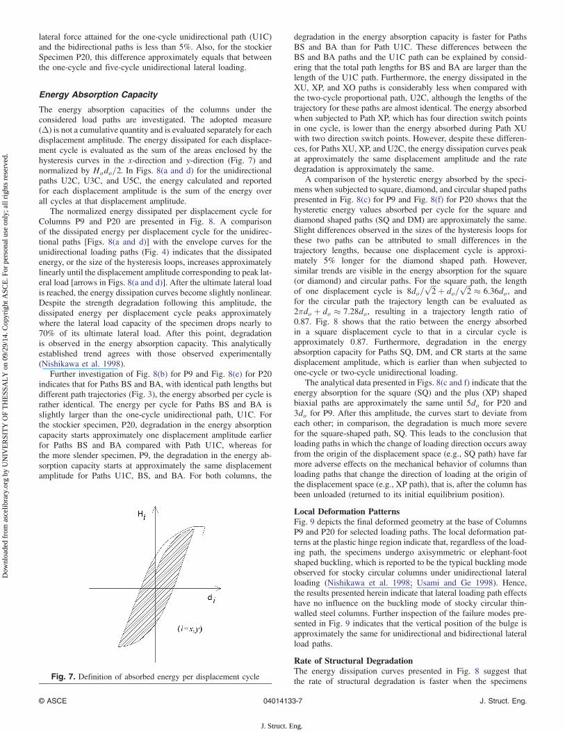
The energy absorption capacities of the columns under theconsidered load paths are investigated. The adopted measure(Δ) is not a cumulative quantity and is evaluated separately for eachdisplacement amplitude. The energy dissipated for each displace-ment cycle is evaluated as the sum of the areas enclosed by thehysteresis curves in the x-direction and y-direction (Fig. 7) andnormalized by Hodo=2. In Figs. 8(a and d) for the unidirectionalpaths U2C, U3C, and U5C, the energy calculated and reportedfor each displacement amplitude is the sum of the energy overall cycles at that displacement amplitude.
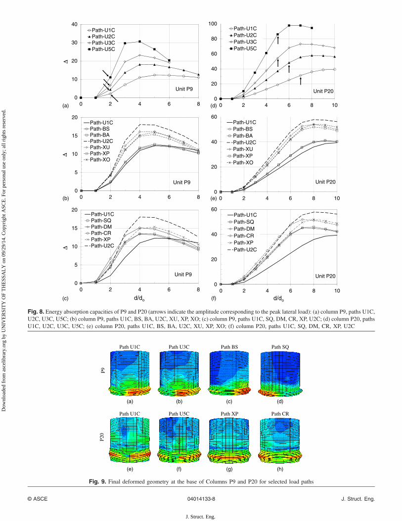
The normalized energy dissipated per displacement cycle forColumns P9 and P20 are presented in Fig. 8. A comparisonof the dissipated energy per displacement cycle for the unidirec-tional paths [Figs. 8(a and d)] with the envelope curves for theunidirectional loading paths (Fig. 4) indicates that the dissipatedenergy, or the size of the hysteresis loops, increases approximatelylinearly until the displacement amplitude corresponding to peak lat-eral load [arrows in Figs. 8(a and d)]. After the ultimate lateral loadis reached, the energy dissipation curves become slightly nonlinear.Despite the strength degradation following this amplitude, thedissipated energy per displacement cycle peaks approximatelywhere the lateral load capacity of the specimen drops nearly to70% of its ultimate lateral load. After this point, degradationis observed in the energy absorption capacity. This analyticallyestablished trend agrees with those observed experimentally(Nishikawa et al. 1998).
Further investigation of Fig. 8(b) for P9 and Fig. 8(e) for P20indicates that for Paths BS and BA, with identical path lengths butdifferent path trajectories (Fig. 3), the energy absorbed per cycle israther identical. The energy per cycle for Paths BS and BA isslightly larger than the one-cycle unidirectional path, U1C. Forthe stockier specimen, P20, degradation in the energy absorptioncapacity starts approximately one displacement amplitude earlierfor Paths BS and BA compared with Path U1C, whereas forthe more slender specimen, P9, the degradation in the energy ab-sorption capacity starts at approximately the same displacementamplitude for Paths U1C, BS, and BA. For both columns, the
degradation in the energy absorption capacity is faster for PathsBS and BA than for Path U1C. These differences between theBS and BA paths and the U1C path can be explained by consid-ering that the total path lengths for BS and BA are larger than thelength of the U1C path. Furthermore, the energy dissipated in theXU, XP, and XO paths is considerably less when compared withthe two-cycle proportional path, U2C, although the lengths of thetrajectory for these paths are almost identical. The energy absorbedwhen subjected to Path XP, which has four direction switch pointsin one cycle, is lower than the energy absorbed during Path XUwith two direction switch points. However, despite these differen-ces, for Paths XU, XP, and U2C, the energy dissipation curves peakat approximately the same displacement amplitude and the ratedegradation is approximately the same.
A comparison of the hysteretic energy absorbed by the speci-mens when subjected to square, diamond, and circular shaped pathspresented in Fig. 8(c) for P9 and Fig. 8(f) for P20 shows that thehysteretic energy values absorbed per cycle for the square anddiamond shaped paths (SQ and DM) are approximately the same.Slight differences observed in the sizes of the hysteresis loops forthese two paths can be attributed to small differences in thetrajectory lengths, because one displacement cycle is approxi-mately 5% longer for the diamond shaped path. However,similar trends are visible in the energy absorption for the square(or diamond) and circular paths. For the square path, the lengthof one displacement cycle is 8do=
ffiffiffi2
p þ do=ffiffiffi2
p ≈ 6.36do, andfor the circular path the trajectory length can be evaluated as2πdo þ do ≈ 7.28do, resulting in a trajectory length ratio of0.87. Fig. 8 shows that the ratio between the energy absorbedin a square displacement cycle to that in a circular cycle isapproximately 0.87. Furthermore, degradation in the energyabsorption capacity for Paths SQ, DM, and CR starts at the samedisplacement amplitude, which is earlier than when subjected toone-cycle or two-cycle unidirectional loading.
The analytical data presented in Figs. 8(c and f) indicate that theenergy absorption for the square (SQ) and the plus (XP) shapedbiaxial paths are approximately the same until 5do for P20 and3do for P9. After this amplitude, the curves start to deviate fromeach other; in comparison, the degradation is much more severefor the square-shaped path, SQ. This leads to the conclusion thatloading paths in which the change of loading direction occurs awayfrom the origin of the displacement space (e.g., SQ path) have farmore adverse effects on the mechanical behavior of columns thanloading paths that change the direction of loading at the origin ofthe displacement space (e.g., XP path), that is, after the column hasbeen unloaded (returned to its initial equilibrium position).
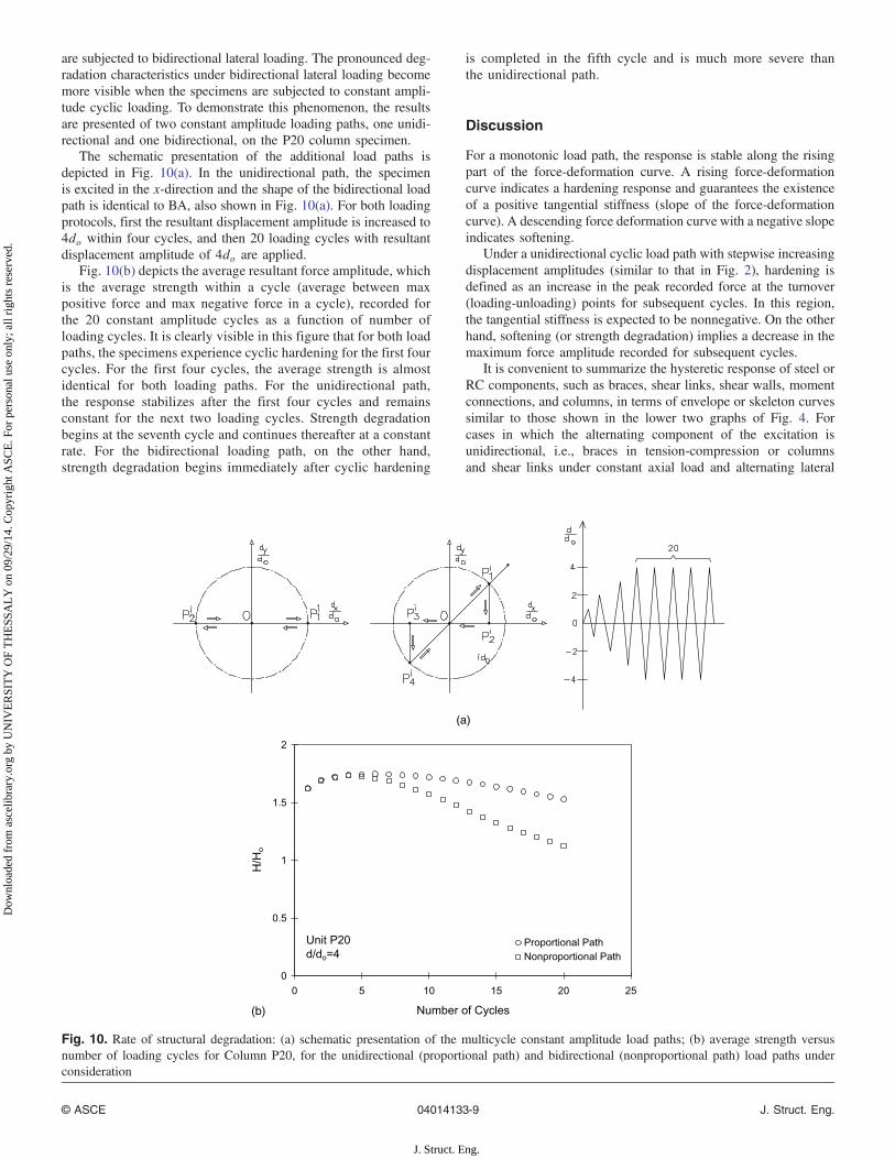
Local Deformation PatternsFig. 9 depicts the final deformed geometry at the base of ColumnsP9 and P20 for selected loading paths. The local deformation pat-terns at the plastic hinge region indicate that, regardless of the load-ing path, the specimens undergo axisymmetric or elephant-footshaped buckling, which is reported to be the typical buckling modeobserved for stocky circular columns under unidirectional lateralloading (Nishikawa et al. 1998; Usami and Ge 1998). Hence,the results presented herein indicate that lateral loading path effectshave no influence on the buckling mode of stocky circular thin-walled steel columns. Further inspection of the failure modes pre-sented in Fig. 9 indicates that the vertical position of the bulge isapproximately the same for unidirectional and bidirectional lateralload paths.
Rate of Structural DegradationThe energy dissipation curves presented in Fig. 8 suggest thatthe rate of structural degradation is faster when the specimensFig. 7. Definition of absorbed energy per displacement cycle
© ASCE 04014133-7 J. Struct. Eng.
J. Struct. Eng.
Dow
nloa
ded
from
asc
elib
rary
.org
by
UN
IVE
RSI
TY
OF
TH
ESS
AL
Y o
n 09
/29/
14. C
opyr
ight
ASC
E. F
or p
erso
nal u
se o
nly;
all
righ
ts r
eser
ved.
0
10
20
30
40
∆∆
∆
Path-U1CPath-U2CPath-U3CPath-U5C
Unit P9
(a)0
20
40
60
80
100
0 2 4 6 8 0 2 4 6 8 10
Path-U1CPath-U2CPath-U3CPath-U5C
Unit P20
(d)
0
5
10
15
20Path-U1CPath-BSPath-BAPath-U2CPath-XUPath-XPPath-XO
Unit P9
(b)0
20
40
60Path-U1CPath-BSPath-BAPath-U2CPath-XUPath-XPPath-XO
Unit P20
(e)
0
5
10
15
20
d/do
Path-U1CPath-SQPath-DMPath-CRPath-XPPath-U2C
Unit P9
(c)
0
20
40
60
0 2 4 6 8 0 2 4 6 8 10
0 2 4 6 8 0 2 4 6 8 10d/do
Path-U1CPath-SQPath-DMPath-CRPath-XPPath-U2C
Unit P20
(f)
Fig. 8. Energy absorption capacities of P9 and P20 (arrows indicate the amplitude corresponding to the peak lateral load): (a) column P9, paths U1C,U2C, U3C, U5C; (b) column P9, paths U1C, BS, BA, U2C, XU, XP, XO; (c) column P9, paths U1C, SQ, DM, CR, XP, U2C; (d) column P20, pathsU1C, U2C, U3C, U5C; (e) column P20, paths U1C, BS, BA, U2C, XU, XP, XO; (f) column P20, paths U1C, SQ, DM, CR, XP, U2C
Path U1C Path U3C Path BS Path SQ
P9
Path U1C Path U5C Path XP Path CR
P20
(a) (b) (c) (d)
(e) (f) (g) (h)
Fig. 9. Final deformed geometry at the base of Columns P9 and P20 for selected load paths
© ASCE 04014133-8 J. Struct. Eng.
J. Struct. Eng.
Dow
nloa
ded
from
asc
elib
rary
.org
by
UN
IVE
RSI
TY
OF
TH
ESS
AL
Y o
n 09
/29/
14. C
opyr
ight
ASC
E. F
or p
erso
nal u
se o
nly;
all
righ
ts r
eser
ved.
are subjected to bidirectional lateral loading. The pronounced deg-radation characteristics under bidirectional lateral loading becomemore visible when the specimens are subjected to constant ampli-tude cyclic loading. To demonstrate this phenomenon, the resultsare presented of two constant amplitude loading paths, one unidi-rectional and one bidirectional, on the P20 column specimen.
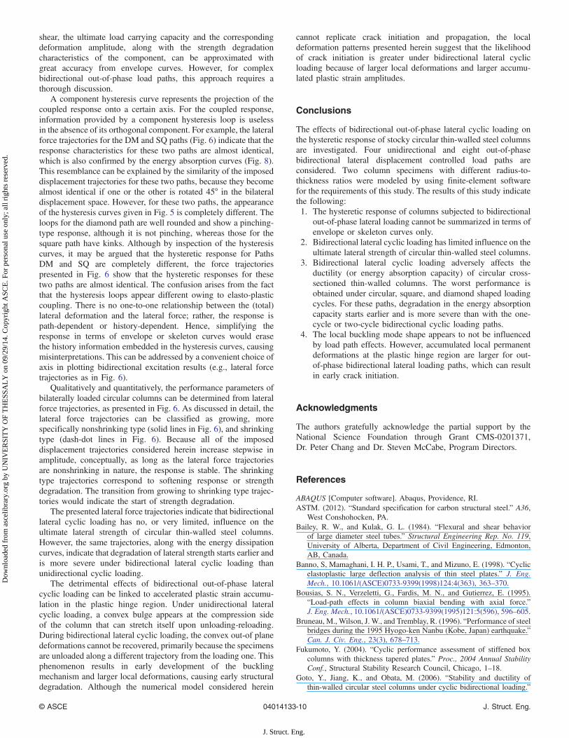
The schematic presentation of the additional load paths isdepicted in Fig. 10(a). In the unidirectional path, the specimenis excited in the x-direction and the shape of the bidirectional loadpath is identical to BA, also shown in Fig. 10(a). For both loadingprotocols, first the resultant displacement amplitude is increased to4do within four cycles, and then 20 loading cycles with resultantdisplacement amplitude of 4do are applied.
Fig. 10(b) depicts the average resultant force amplitude, whichis the average strength within a cycle (average between maxpositive force and max negative force in a cycle), recorded forthe 20 constant amplitude cycles as a function of number ofloading cycles. It is clearly visible in this figure that for both loadpaths, the specimens experience cyclic hardening for the first fourcycles. For the first four cycles, the average strength is almostidentical for both loading paths. For the unidirectional path,the response stabilizes after the first four cycles and remainsconstant for the next two loading cycles. Strength degradationbegins at the seventh cycle and continues thereafter at a constantrate. For the bidirectional loading path, on the other hand,strength degradation begins immediately after cyclic hardening
is completed in the fifth cycle and is much more severe thanthe unidirectional path.
Discussion
For a monotonic load path, the response is stable along the risingpart of the force-deformation curve. A rising force-deformationcurve indicates a hardening response and guarantees the existenceof a positive tangential stiffness (slope of the force-deformationcurve). A descending force deformation curve with a negative slopeindicates softening.
Under a unidirectional cyclic load path with stepwise increasingdisplacement amplitudes (similar to that in Fig. 2), hardening isdefined as an increase in the peak recorded force at the turnover(loading-unloading) points for subsequent cycles. In this region,the tangential stiffness is expected to be nonnegative. On the otherhand, softening (or strength degradation) implies a decrease in themaximum force amplitude recorded for subsequent cycles.
It is convenient to summarize the hysteretic response of steel orRC components, such as braces, shear links, shear walls, momentconnections, and columns, in terms of envelope or skeleton curvessimilar to those shown in the lower two graphs of Fig. 4. Forcases in which the alternating component of the excitation isunidirectional, i.e., braces in tension-compression or columnsand shear links under constant axial load and alternating lateral
(a)
(b)
0
0.5
1
1.5
2
0 5 10 15 20 25
Number of Cycles
H/H
o
Proportional PathNonproportional Path
Unit P20d/do=4
Fig. 10. Rate of structural degradation: (a) schematic presentation of the multicycle constant amplitude load paths; (b) average strength versusnumber of loading cycles for Column P20, for the unidirectional (proportional path) and bidirectional (nonproportional path) load paths underconsideration
© ASCE 04014133-9 J. Struct. Eng.
J. Struct. Eng.
Dow
nloa
ded
from
asc
elib
rary
.org
by
UN
IVE
RSI
TY
OF
TH
ESS
AL
Y o
n 09
/29/
14. C
opyr
ight
ASC
E. F
or p
erso
nal u
se o
nly;
all
righ
ts r
eser
ved.
shear, the ultimate load carrying capacity and the correspondingdeformation amplitude, along with the strength degradationcharacteristics of the component, can be approximated withgreat accuracy from envelope curves. However, for complexbidirectional out-of-phase load paths, this approach requires athorough discussion.
A component hysteresis curve represents the projection of thecoupled response onto a certain axis. For the coupled response,information provided by a component hysteresis loop is uselessin the absence of its orthogonal component. For example, the lateralforce trajectories for the DM and SQ paths (Fig. 6) indicate that theresponse characteristics for these two paths are almost identical,which is also confirmed by the energy absorption curves (Fig. 8).This resemblance can be explained by the similarity of the imposeddisplacement trajectories for these two paths, because they becomealmost identical if one or the other is rotated 45° in the bilateraldisplacement space. However, for these two paths, the appearanceof the hysteresis curves given in Fig. 5 is completely different. Theloops for the diamond path are well rounded and show a pinching-type response, although it is not pinching, whereas those for thesquare path have kinks. Although by inspection of the hysteresiscurves, it may be argued that the hysteretic response for PathsDM and SQ are completely different, the force trajectoriespresented in Fig. 6 show that the hysteretic responses for thesetwo paths are almost identical. The confusion arises from the factthat the hysteresis loops appear different owing to elasto-plasticcoupling. There is no one-to-one relationship between the (total)lateral deformation and the lateral force; rather, the response ispath-dependent or history-dependent. Hence, simplifying theresponse in terms of envelope or skeleton curves would erasethe history information embedded in the hysteresis curves, causingmisinterpretations. This can be addressed by a convenient choice ofaxis in plotting bidirectional excitation results (e.g., lateral forcetrajectories as in Fig. 6).
Qualitatively and quantitatively, the performance parameters ofbilaterally loaded circular columns can be determined from lateralforce trajectories, as presented in Fig. 6. As discussed in detail, thelateral force trajectories can be classified as growing, morespecifically nonshrinking type (solid lines in Fig. 6), and shrinkingtype (dash-dot lines in Fig. 6). Because all of the imposeddisplacement trajectories considered herein increase stepwise inamplitude, conceptually, as long as the lateral force trajectoriesare nonshrinking in nature, the response is stable. The shrinkingtype trajectories correspond to softening response or strengthdegradation. The transition from growing to shrinking type trajec-tories would indicate the start of strength degradation.
The presented lateral force trajectories indicate that bidirectionallateral cyclic loading has no, or very limited, influence on theultimate lateral strength of circular thin-walled steel columns.However, the same trajectories, along with the energy dissipationcurves, indicate that degradation of lateral strength starts earlier andis more severe under bidirectional lateral cyclic loading thanunidirectional cyclic loading.
The detrimental effects of bidirectional out-of-phase lateralcyclic loading can be linked to accelerated plastic strain accumu-lation in the plastic hinge region. Under unidirectional lateralcyclic loading, a convex bulge appears at the compression sideof the column that can stretch itself upon unloading-reloading.During bidirectional lateral cyclic loading, the convex out-of planedeformations cannot be recovered, primarily because the specimensare unloaded along a different trajectory from the loading one. Thisphenomenon results in early development of the bucklingmechanism and larger local deformations, causing early structuraldegradation. Although the numerical model considered herein
cannot replicate crack initiation and propagation, the localdeformation patterns presented herein suggest that the likelihoodof crack initiation is greater under bidirectional lateral cyclicloading because of larger local deformations and larger accumu-lated plastic strain amplitudes.
Conclusions
The effects of bidirectional out-of-phase lateral cyclic loading onthe hysteretic response of stocky circular thin-walled steel columnsare investigated. Four unidirectional and eight out-of-phasebidirectional lateral displacement controlled load paths areconsidered. Two column specimens with different radius-to-thickness ratios were modeled by using finite-element softwarefor the requirements of this study. The results of this study indicatethe following:1. The hysteretic response of columns subjected to bidirectional
out-of-phase lateral loading cannot be summarized in terms ofenvelope or skeleton curves only.
2. Bidirectional lateral cyclic loading has limited influence on theultimate lateral strength of circular thin-walled steel columns.
3. Bidirectional lateral cyclic loading adversely affects theductility (or energy absorption capacity) of circular cross-sectioned thin-walled columns. The worst performance isobtained under circular, square, and diamond shaped loadingcycles. For these paths, degradation in the energy absorptioncapacity starts earlier and is more severe than with the one-cycle or two-cycle bidirectional cyclic loading paths.
4. The local buckling mode shape appears to not be influencedby load path effects. However, accumulated local permanentdeformations at the plastic hinge region are larger for out-of-phase bidirectional lateral loading paths, which can resultin early crack initiation.
Acknowledgments
The authors gratefully acknowledge the partial support by theNational Science Foundation through Grant CMS-0201371,Dr. Peter Chang and Dr. Steven McCabe, Program Directors.
References
ABAQUS [Computer software]. Abaqus, Providence, RI.ASTM. (2012). “Standard specification for carbon structural steel.” A36,
West Conshohocken, PA.Bailey, R. W., and Kulak, G. L. (1984). “Flexural and shear behavior
of large diameter steel tubes.” Structural Engineering Rep. No. 119,University of Alberta, Department of Civil Engineering, Edmonton,AB, Canada.
Banno, S, Mamaghani, I. H. P., Usami, T., and Mizuno, E. (1998). “Cyclicelastoplastic large deflection analysis of thin steel plates.” J. Eng.Mech., 10.1061/(ASCE)0733-9399(1998)124:4(363), 363–370.
Bousias, S. N., Verzeletti, G., Fardis, M. N., and Gutierrez, E. (1995).“Load-path effects in column biaxial bending with axial force.”J. Eng. Mech., 10.1061/(ASCE)0733-9399(1995)121:5(596), 596–605.
Bruneau, M., Wilson, J. W., and Tremblay, R. (1996). “Performance of steelbridges during the 1995 Hyogo-ken Nanbu (Kobe, Japan) earthquake.”Can. J. Civ. Eng., 23(3), 678–713.
Fukumoto, Y. (2004). “Cyclic performance assessment of stiffened boxcolumns with thickness tapered plates.” Proc., 2004 Annual StabilityConf., Structural Stability Research Council, Chicago, 1–18.
Goto, Y., Jiang, K., and Obata, M. (2006). “Stability and ductility ofthin-walled circular steel columns under cyclic bidirectional loading.”
© ASCE 04014133-10 J. Struct. Eng.
J. Struct. Eng.
Dow
nloa
ded
from
asc
elib
rary
.org
by
UN
IVE
RSI
TY
OF
TH
ESS
AL
Y o
n 09
/29/
14. C
opyr
ight
ASC
E. F
or p
erso
nal u
se o
nly;
all
righ
ts r
eser
ved.
J. Struct. Eng., 10.1061/(ASCE)0733-9445(2006)132:10(1621),1621–1631.
Goto, Y., Jiang, K., and Obata, M. (2008). “Closure to stability and ductilityof thin-walled circular steel columns under cyclic bidirectional loadingby Yoshiaki Goto, Kunsheng Jiang, and Makoto Obata.” J. Struct. Eng.,867–869, 10.1061/(ASCE)0733-9445(2008)134:5(867).
Goto, Y., Muraki, M., and Obata, M. (2009). “Ultimate state of thin-walledcircular steel columns under bidirectional seismic accelerations.”J. Struct. Eng., 10.1061/(ASCE)ST.1943-541X.0000076, 1481–1490.
Hashimoto, O., Yasunami, H., Mizutani, S., Kobashi, Y., and Nakagawa, T.(1996). “Investigation on the strength and ductility of steel piers withcompact section.” Bridge Found. Eng., 30(8), 135–137 (in Japanese).
Marzullo, M. A., and Ostapenko, A. (1977). “Tests on two high-strengthshort tubular columns.” Rep. No. 406.10, Fritz Engineering Laboratory,Lehigh University, Bethlehem, PA.
Minerals Management Service (MMS). (2007). “Assessment of fixedoffshore platform performance in Hurricanes Katrina and Rita.”MMS Project No.578, U.S. Department of Interior MineralManagement Service Engineering and Research Branch, Herndon, VA.
Mizutani, S., Usami, T., Aoki, T., Itoh, Y., and Okamoto, T. (1996). “Anexperimental study on the cyclic elastoplastic behavior of steel tubularmembers.” J. Struct. Eng., JSCE, 42A, 105–114 (in Japanese).
Nakamura, S., Yasunami, H., Kobayashi, Y., Nakagawa, T., and Mizutani,S. (1997). “An experimental study on the seismic performance of steelbridge piers with less-stiffened and compact sized section.” Proc.,Symp. on Nonlinear Numerical Analysis and Seismic Design of BridgePiers (JSCE), Japan Society of Civil Engineers, Tokyo, 331–338.
Nishikawa, K., Yamamoto, S., Natori, T., Terao, K., Yasunami, H., andTerada, M. (1998). “Retrofitting for seismic upgrading of steel bridgecolumns.” Eng. Struct., 20(4–6), 540–551.
Ostapenko, A., and Grimm, D. F. (1980). “Local buckling of cylindricaltubular columns made of A36 steel.” Rep. No. 450.7, Fritz EngineeringLaboratory, Lehigh University, Bethlehem, PA.
Ostapenko, A., and Gunzelman, S. X. (1976). “Local buckling of tubularsteel columns.” Proc., National Structural Engineering Conf., W. E.Saul and A. H. Peyrol, eds., ASCE, Reston, VA, 549–568.
Qiu, F., Li, W., Pan, P., and Qian, J. (2002). “Experimental tests onreinforced concrete columns under biaxial quasi-static loading.” Eng.Struct., 24(4), 419–428.
Saatcioglu, M., and Ozcebe, G. (1989). “Response of reinforced concretecolumns to simulated seismic loading.” ACI Struct. J., 86(1),3–12.
Stephens, M. J., Kulak, G. L., and Montgomery, C. J. (1982). “Local buck-ling of thin-walled tubular steel members.” Structural Engineering Rep.No. 103, University of Alberta, Department of Civil Engineering,Edmonton, AB, Canada.
Ucak, A. (2009). “Instabilities in thin walled thin columns underthree dimensional nonproportional cyclic loading.” Ph.D. thesis,Department of Civil Engineering, Catholic University of America,Washington, DC.
Ucak, A., and Tsopelas, P. (2006). “Cellular and corrugated cross-sectionalthin walled steel bridge piers/columns.” Struct. Eng. Mech., 24(3),355–374.
Ucak, A., and Tsopelas, P. (2008). “Discussion of stability and ductility ofthin walled circular steel columns under cyclic bidirectional loadingby Yoshiaki Goto, Kunsheng Jiang, and Makoto Obata.” J. Struct.Eng., 10.1061/(ASCE)0733-9445(2008)134:5(865), 865–867.
Ucak, A., and Tsopelas, P. (2011). “Constitutive model for cyclic responseof structural steels with yield plateau.” J. Struct. Eng., 10.1061/(ASCE)ST.1943-541X.0000287, 195–206.
Ucak, A., and Tsopelas, P. (2012). “Accurate modeling of the cyclicresponse of structural components constructed of steel with yieldplateau.” Eng. Struct., 35, 272–280.
Usami, T., and Ge, H. B. (1998). “Cyclic behavior of thin-walledsteel structures-numerical analysis.” Thin Walled Struct., 32(1–3),41–80.
Watanabe, E., Sugiura, K., and Oyawa, W. (2000). “Effects of multidirec-tional displacement paths on the cyclic behavior of rectangular hollowsteel columns.” Struct. Eng. Earthquake Eng., JSCE, 17(1), 69–85.
Wong, Y. L., Paulay, T., and Priestley, M. J. N. (1993). “Response of cir-cular reinforced concrete columns to multi-directional seismic attack.”ACI Struct. J., 90(2), 180–190.
© ASCE 04014133-11 J. Struct. Eng.
J. Struct. Eng.
Dow
nloa
ded
from
asc
elib
rary
.org
by
UN
IVE
RSI
TY
OF
TH
ESS
AL
Y o
n 09
/29/
14. C
opyr
ight
ASC
E. F
or p
erso
nal u
se o
nly;
all
righ
ts r
eser
ved.
Related Documents