TRANSPORTATION OF LIVING QUARTERS BEHALF OF TOMBUA LANDANA PROJECT ANGOLA, WEST AFRICA By: ANDREW HARYANTO 1525985 FENNY WIYONO 1525983 Accomplished as Final Thesis Report CIVIL ENGINEERING FACULTY OF NATURE AND SCIENCE HOGESCHOOL UTRECHT THE NETHERLANDS 2007

Welcome message from author
This document is posted to help you gain knowledge. Please leave a comment to let me know what you think about it! Share it to your friends and learn new things together.
Transcript

TRANSPORTATION OF LIVING QUARTERS BEHALF OF TOMBUA LANDANA PROJECT
ANGOLA, WEST AFRICA
By: ANDREW HARYANTO 1525985 FENNY WIYONO 1525983
Accomplished as Final Thesis Report
CIVIL ENGINEERING FACULTY OF NATURE AND SCIENCE
HOGESCHOOL UTRECHT THE NETHERLANDS
2007

International Bachelor in Civil Engineering i Transportation of Living Quarters-Tombua Landana Project
Approval
FINAL THESIS ABOUT TRANSPORTATION OF LIVING QUARTERS
BEHALF OF TOMBUA LANDANA PROJECT ANGOLA, WEST AFRICA
Discipline Name Signature Date
Tutor I ir. Frans van Heerden
Tutor II ir. Rene Camerik
Supervisor I ing. Pieter van Greuningen
Supervisor II ing. Hans de Gruyter

International Bachelor in Civil Engineering ii Transportation of Living Quarters-Tombua Landana Project
SUMMARY
The oil mining increased along with the higher demand of energy in the
world. Fulfilling this requirement, Chevron Corporation and several other
companies, intends to explore a new oil field by installing a new offshore oil
platform in block 14, Angola, West Africa called as the Tombua Landana project.
The complete platform itself consists of several parts. One of them is the
Living Quarters (LQ) which is built in Houston, USA. It is functioned as the
accommodation for offshore workers during their working period over there. In
this project Heerema Marine Contractors (HMC) as the Transportation and
Installation Contractors is responsible to transport the LQ safely and on schedule.
For this project, the internship students were responsible to design the
support structures which are called grillages and seafastenings to secure the LQ
during the transportation. The students did the internship project as group so that
the design can be optimized better than individually. During the internship, the
students studied literatures such as the HMC’s standard criteria, AISC code
(American Institute Steel Construction), offshore manuals, and discussed the
design with the internal experts. The students worked four days in the office and
one day in the school per week for 5 months.
There are many aspects that must be considered for transporting LQ since
the sea parameters influence to the transportation as static and dynamic loads. The
main idea of the design is to transfer the loads from LQ through the support
structure to the barge’s strong points in a proper way. The transferred load must
be less than the capacity of the barge otherwise the engineer must redesign the
support structures. In the end, the support structure must be friendly fabricated
and suitable for load-out phase, transportation phase, and installation phase.
By doing this internship, the students gained a lot of knowledge about
offshore engineering, experiences as employees in the Dutch-International
company, applied the theoretical lessons from school in a real project, and got
familiar with the work atmosphere in the Netherlands where they can free to ask
anything.

International Bachelor in Civil Engineering iii Transportation of Living Quarters-Tombua Landana Project
PREFACE
Thanks to Jesus Christ, for his grace and his faithfulness so this final
thesis report can be accomplished in time. The report is used as one of the
graduation requirements for Double Bachelor’s Degree Program in Hogeschool
Utrecht both with Gadjah Mada University and Petra Christian University.
Therefore, the author would say thank to:
1. ing. Pieter van Greuningen as the supervisor 1 from Heerema Marine
Contractors.
2. ing. Hans de Gruyter as the supervisor 2 from Heerema Marine
Contractors.
3. Ir. Frans van Heerden as the supervisor 1 from the Hogeschool Utrecht.
4. Ir. Rene Camerik as the supervisor 2 from the Hogeschool Utrecht.
5. All of Tombua Landana project team member.
6. Other staff from Heerema Marine Contractors.
7. Prof. Ir. Siti Malkamah, M.Sc., Ph.D., as the teacher from Gadjah Mada
University, Yogyakarta, Indonesia.
8. Dra. Lisa Setyawati, M.Ed., as the head of International Affairs and
Cooperation Petra Christian University.
9. Our family in Indonesia who support us faithfully.
10. Our international classmates, Shenny, Maria, Suwanda, Eric and Natie.
Finally, the authors realize that this final thesis is still not perfect yet.
Therefore, the authors expect some recommendation from the readers to make it
better.
Utrecht-Leiden, 12th June 2007
Andrew Haryanto ([email protected])
Fenny Wiyono ([email protected])

International Bachelor in Civil Engineering iv Transportation of Living Quarters-Tombua Landana Project
LIST OF CONTENTS
APPROVAL PAGE ....................................................................................... i ABSTRACT ................................................................................................... ii PREFACE ...................................................................................................... iii LIST OF CONTENTS ................................................................................... iv LIST OF TABLES ......................................................................................... vi LIST OF FIGURES ........................................................................................ vii LIST OF ABBREVIATIONS ........................................................................ ix LIST OF DEFINITIONS ............................................................................... x CHAPTER 1 INTRODUCTION
1.1. Project Description ........................................................................ 1 1.2. Objectives ...................................................................................... 3 1.3. Boundary Conditions ..................................................................... 3 1.4. Benefit of Internship Project .......................................................... 5
CHAPTER 2 LIVING QUARTERS AND BARGE
2.1. Living Quarters .............................................................................. 6 2.1.1. Living Quarters Specifications ........................................... 8
2.2. Barge .............................................................................................. 8 2.2.1. Crowley-411 Specifications ............................................... 9
2.2.2. Ballast Tanks ...................................................................... 10 2.3. Living Quarters Position on the Barge .......................................... 12
CHAPTER 3 TRANSPORTATION ASPECTS 3.1. Transportation Descriptions .......................................................... 14 3.2. Transportation Forces .................................................................... 16 3.3. Sea Parameters ............................................................................... 17
CHAPTER 4 GRILLAGE AND SEAFASTENINGS DESIGN 4.1. Grillage .......................................................................................... 19 4.1.1. Grillage Concept Design .................................................... 19
4.1.1.1. Wing Plate ............................................................ 24 4.1.1.2. End Stiffeners ....................................................... 26 4.1.1.3. Welds ................................................................... 27
4.1.2. Grillage Calculations .......................................................... 29 4.2. Seafastening ................................................................................... 29 4.2.1. Seafastening Concept Design ............................................. 30

International Bachelor in Civil Engineering v Transportation of Living Quarters-Tombua Landana Project
4.2.2. Seafastening Calculations ................................................... 32 4.3. Barge Capacity Checks .................................................................. 32 4.3.1. Local Capacity Check ......................................................... 32 4.3.2. Web Frame Capacity Check ............................................... 33 4.3.3. Rail Girder Capacity Check ................................................ 33
CHAPTER 5 TRANSPORTATION AND INSTALLATION PHASE 5.1. Transportation Phase ..................................................................... 36 5.1.1. Load-Out ............................................................................. 36 5.1.2. Sailing Overseas ................................................................. 40 5.1.2.1. Ballast Arrangement ............................................ 41 5.1.2.2. Bollard Pull .......................................................... 42 5.1.2.3. Tug Boat ............................................................... 45 5.1.2.4. Towing Equipments ............................................. 45 5.2. Installation Phase ........................................................................... 48
CHAPTER 6 CONCLUSION AND SUGGESTIONS 6.1. Conclusions ................................................................................... 51 6.2. Suggestions .................................................................................... 52
REFERENCES ............................................................................................... 53 LIST OF FORMULAS .................................................................................. 54 LIST OF APPENDIXES ................................................................................ 72

International Bachelor in Civil Engineering vi Transportation of Living Quarters-Tombua Landana Project
LIST OF TABLES
2.1. Ballast Tank Capacity ........................................................................... 11
3.1. Noble Denton Motion Criteria .............................................................. 17
4.1. Fillet Weld Minimum Size (AWS) ....................................................... 28
5.1. Tug Efficiency ....................................................................................... 44
5.2. Towline Breaking Load (MBL) ............................................................ 47

International Bachelor in Civil Engineering vii Transportation of Living Quarters-Tombua Landana Project
LIST OF FIGURES
1.1. Offshore Oil Platforms .......................................................................... 2
1.2. Typical Transport Layout ...................................................................... 2
1.3. Transportation Routes and Place’s Inset ............................................... 4
2.1. Living Quarters ..................................................................................... 6
2.2. Living Quarters on the Main Platform .................................................. 7
2.3. Thialf ..................................................................................................... 7
2.4. Living Quarters and Its Dimensions ..................................................... 8
2.5. Strong Points of Living Quarters .......................................................... 9
2.6. Crowley-411 .......................................................................................... 9
2.7. General Plan of Crowley-411 ................................................................ 10
2.8. Ballast Tanks Configuration of Crowley-411 ....................................... 11
2.9. Living Quarters on the Crowley-411 Layout ........................................ 13
3.1. Transportation Routes ........................................................................... 15
3.2. Barge Motion ........................................................................................ 16
4.1. Grillage Beam ....................................................................................... 19
4.2. Shim Plate ............................................................................................... 20
4.3 Load Distribution of Living Quarters ................................................... 21
4.4. Grillage Beam Layout ........................................................................... 22
4.5 Roll to Starboard Forces ....................................................................... 23
4.6. Pitch to Bow Forces .............................................................................. 23
4.7. Wing Plate ............................................................................................. 25
4.8. End Stiffener ......................................................................................... 27
4.9. Fillet Weld ............................................................................................. 28
4.10. Seafastening Layout ................................................................................ 30
4.11. Roll Brace ............................................................................................. 31
4.12. Pitch Stopper ......................................................................................... 31
4.13. Concept of Load Distribution ................................................................ 33
4.14. Typical Rail Girder ............................................................................... 34
4.15. Rail Girder ............................................................................................. 34
International Bachelor in Civil Engineering viii Transportation of Living Quarters-Tombua Landana Project
5.1. Skid Beam ............................................................................................. 36
5.2. Trailers Moving a Module .................................................................... 37
5.3. Delta Yard ............................................................................................. 38
5.4. First Phase ............................................................................................. 39
5.5. Second Phase ......................................................................................... 39
5.6. Cross Section of Grillages and Trailer (HMC’s Proposal) ................... 40
5.7. Trim Condition (Starboard View)........................................................... 41
5.8 List Condition (Stern View).................................................................... 42
5.9. Wind Load ............................................................................................. 43
5.10. Wind Direction to the Cargo ................................................................. 43
5.11. Main Tow Bridle with Recovery System .............................................. 46
5.12. Emergency Towing Gear ...................................................................... 46
5.13. Barge and Its Tug Boat ......................................................................... 47
5.14. Living Quarters Installation .................................................................. 50

International Bachelor in Civil Engineering ix Transportation of Living Quarters-Tombua Landana Project
LIST OF ABBREVIATIONS
AISC American Institute of Steel Construction AWS American Welding Society BP Bollard Pull C.o.G. Centre of Gravity DEC Delta Engineering Cooperation DSME Daewoo Shipbuilding and Marine Engineering EPCI Engineering, Procurement, Construction, and Installation ft. foot HMC Heerema Marine Contractors Hsig Significant wave height kN Kilonewton LOA Length Over All LWL Length on water line. m meter mm millimeter m/s meter per second MBL Minimum Breaking Load mT metric ton N/A Not Applicable PG Plate Girder Te Tug Efficiency TPR Towline Pull Required ULC Ultimate Load Capacity WF Wide Flange

International Bachelor in Civil Engineering x Transportation of Living Quarters-Tombua Landana Project
LIST OF DEFINITIONS
Ballast A heavy substance such as water, sand or iron placed in
special compartments of a vessel or structure to influence
its weight or stability.
Barge A flat-bottomed boat, to serve special purpose such as
transporting platform modules.
Bollard To fix a mooring rope of a vessel
Bollard Pull The pulling force of a tug boat
Bow The forward part of the hull of a ship or boat, the point
that is most forward when the vessel is underway
Brace A diagonal connection (a beam or pipe) to give a
construction more stability or to restrain a structure from
sideways motion
Breaking load Certified minimum breaking load of wire rope, chain or
shackles.
Bridle A span of chain, wire, or rope that can be secured at both
ends to an object and slung from its center point.
Bulkhead A watertight division-construction to create different
compartments in a barge or structure so that it will be
ballasted accurately
Cargo The item to be transported by a barge.
C.o.G. (Centre of Gravity) the theoretical point in the cross-
section of a body in which the resultant of the gravity
forces is acting
Deck The general term for a working area on an offshore
platform or of a barge
Draft The vertical distance from the waterline to the bottom of
the hull.
Dry Weight The weight of the object without allowances for
inaccuracies, contingencies, and rigging

International Bachelor in Civil Engineering xi Transportation of Living Quarters-Tombua Landana Project
Girder A large support beam used in construction, normally of
iron or steel.
Grillage Steel construction that is functioned to secure the cargo to
the barge deck, improve the distribution of the weight of
the cargo into the supporting underground (land or barge)
Heave Linear vertical (up/down) motion
Hull The body of a ship or boat
Lift weight The design weight which is included the allowance for
dynamic amplification (shock load)
Load-out To put large cargo from construction-site (quay) onto
vessels or barges, by use of skid beams or trailers (or
lifting)
Pitch The rotation of the barge about the transverse (side-to-
side) axis
Portside (PS) Looking towards the bow end of the ship it is the left site
Quay A solid embankment or structure parallel to a waterway
used for loading and unloading ships.
Rigging All lifting equipment which consists of grommets, slings,
shackles, and spreaderbars.
Roll The rotation of the barge about the longitudinal
(front/back) axis
Scow Any of various flat-bottomed boats with sloping ends
Seafastening Steel structures to provide and secure the shipload
Shackle An open or closed link of various shapes with extended
legs; each leg has a transverse hole to accommodate a pin
and to fix a sling to a padeye.
Skid A metal runner for transporting load over the structural
element below.
Sling A length of cable laid steel wire with eyes on both ends
used to make the connection between the lift points on the
structure to be lifted and the crane hook

International Bachelor in Civil Engineering xii Transportation of Living Quarters-Tombua Landana Project
Starboard (SB) When looking towards the bow end of the ship: the right
side
Stern End of the ship in which direction it is usually not sailing
(normally the propellers are fitted to this end)
Surge Linear longitudinal (front/back) motion
Sway Linear lateral (side to side) motion
Towing equipment All towing equipment on the towing boat and the towed
object used to effect the towage.
Towline pull required (TPR) The towline pull computed to hold the tow or a
cargo by a towage or a voyage.
Trim The longitudinal out-of-level situation of a vessel or barge
Tugboat (tug) A boat used to maneuver, primarily by towing or pushing
other vessels in harbors, over the open sea or through
rivers and canals.
Tugger line Steering line
Yaw The rotation of the barge about the vertical (up-down)
axis

International Bachelor in Civil Engineering 1 Transportation of Living Quarters-Tombua Landana Project
CHAPTER 1
INTRODUCTION
1.1. Project Description
The development of oil and gas offshore mining has been increased along
with the development of industries in the world. One of the countries that had
been developed rapidly for its oil and gas mining is Angola, West Africa. Angola
is the second of the largest oil producing countries in Africa, after Nigeria.
Situated in the lower Congo Basin, offshore Angola, there is block 14 where nine
major oil offshore fields were discovered since 1997: Kuito (1997), Benguela
(1998), Belize (1998), Landana (1998), Lobito (2000), Tomboco (2000), Tombua
(2001), Gabela (2002), Negage (2002).
Those nine major oil offshore fields were discovered by Chevron Texaco
which is one of the largest energy companies in the world and its partners
(Sonangol P&P, TotalFinaElf, AGIP, and Petrogal). One of those fields which
was explored is Tombua and Landana field and the project was named Tombua
Landana. This project will be Chevron Texaco’s third deepwater offshore project
in West Africa. For executing the Tombua Landana project, Chevron Texaco has
awarded Daewoo Shipbuilding and Marine Engineering (DSME) an EPCI
(Engineering, Procurement, Construction, and Installation) contract for the
platform including the pipelines. In this project, DSME has asked Heerema
Marine Contractors (HMC) as the subcontractor for the transportation and
installation of the platforms while Noble Denton was chosen as a warranty
surveyor.
The oil platform is needed for oil and gas mining. It is a large structure
which is functioned as the house of workers and machinery to drill and then
produce oil and natural gas in the ocean. Different oil platform are illustrated in
Figure 1.1. The oil platform for Tombua Landana project is compliant piled tower
platform which is built on steel jackets anchored directly onto the seabed. This
kind of platforms is economically feasible for installation in water depths up to
about 3000 feet (910m).

International Bachelor in Civil Engineering 2 Transportation of Living Quarters-Tombua Landana Project
Figure 1.1. Type of Offshore Oil Platforms
In the oil offshore mining platform itself, of course, an accommodation is
needed for the workers to live in. Its specific name is Living Quarters (LQ) which
is built by Delta Engineering Corporation (DEC) in Delta yard, Houston, USA. To
transport it to the offshore site a barge is needed. During the transport, the LQ will
have to be supported and restraint against movement. The structures, those are
required for this purpose, called “grillage” and “seafastening” (Figure 1.2.).
Figure 1.2. Typical Transport Layout

International Bachelor in Civil Engineering 3 Transportation of Living Quarters-Tombua Landana Project
This internship project is focused on the transportation of LQ from
Houston, USA to Angola, West Africa (Figure 1.2.), including the design of
grillage and seafastening. The transportation is a part of the whole phases and
relates to another phase. In this internship project, installation and load-out must
be considered as well.
1.2. Objectives
The objective of this project is to transport LQ from Houston, USA to
Angola, West Africa safely, on schedule, and friendly fabricated. Fulfilling these
requirements, the steel structures are needed to keep the cargo (Living Quarters)
in its fixed position during the transportation within consideration to the sea
parameters during the departure window.
1.3. Boundary Conditions
Since there are plenty of factors involved during the transportation of the
cargo, the boundary conditions must be measured before doing the next steps. The
boundary conditions for this internship project are mentioned below:
1. The transportation forces are determined according to Noble Denton
criteria or are supplied by specialist marine engineers.
2. The applicable codes and standards according to American Standard for
Steel Construction (AISC).
3. The calculation method, based on Heerema Standard Criteria.
4. The cargo specifications are determined by the client (DSME).
5. The trailers arrangements are determined by Mammoet and Delta
Engineering Corporation (DEC). Heerema Marine Contractors (HMC)
has a review function.

International Bachelor in Civil Engineering 4 Transportation of Living Quarters-Tombua Landana Project

International Bachelor in Civil Engineering 5 Transportation of Living Quarters-Tombua Landana Project
1.4. Benefit of the Internship Project
For students
This project can give a new experience where students can apply their
knowledge that they already got during their study. Students can learn
how to apply the American standard in a real project and get familiar
with the real work atmosphere in Netherlands, by cooperation with
internal experts in their fields.
For company
The final thesis report can be used as a reference for the project.
For academic purpose
This report can be used as basic knowledge for other research, related
with offshore platforms transportation projects.

International Bachelor in Civil Engineering 6 Transportation of Living Quarters-Tombua Landana Project
CHAPTER 2
Living Quarters and Barge
2.1. Living Quarters
The cargo which is transported in this project is called Living Quarters
(LQ) (Figure 2.1). LQ is the accommodation for the workers during their work on
an offshore platform. It is designed and built by Delta Engineering Corporation
(DEC) in Delta Engineering yard, Houston, USA. There is a certain reason why
the LQ is built in Houston instead of Angola. Insufficient equipment and expertise
in Angola caused the LQ is constructed in Houston and furthermore the oil
company (Chevron Texaco) has cooperated with the fabricator (DEC) because of
their specialization for constructing LQ.
Figure 2.1. Living Quarters
LQ is a relatively small part compared to the main platform but it plays
an important role. It will be placed all together with the other constructions to
form a complete oil drilling platform (Figure 2.2.). The installation of LQ will be
done by Thialf, Heerema’s crane vessel (Figure 2.3.). In this internship project,
the general part of the installation phase will be discussed.

International Bachelor in Civil Engineering 7 Transportation of Living Quarters-Tombua Landana Project
Figure 2.2. Living Quarters on the Main Platform
Figure 2.3. Thialf

International Bachelor in Civil Engineering 8 Transportation of Living Quarters-Tombua Landana Project
2.1.1. Living Quarters Specifications
LQ is a steelwork construction building which has four stories (Figure
2.4.). It is made from high grade steel, Fe510. It can accommodate 120 beds.
Figure 2.4. Living Quarters and Its Dimensions
There are twelve strong points in the LQ that function to transmit its
weight to the structural elements below (strong points of the barge). These strong
points are located in the row A and row C. Each row has six strong points that can
be seen in Figure 2.5. These strong points will also be used for considering
grillage and seafastening design.
2.2. Barge
The cargo transportation needs a ship called barge to across through the
sea. A barge is a flat bottomed ship, used for transportation of heavy goods. Most
of them are not self propelled and need to be pulled by tug boats. The barge, used
for this project, is Crowley-411 (Figure 2.6.). Both the barge and the tug boat are
provided by Crowley Maritime Corporation.

International Bachelor in Civil Engineering 9 Transportation of Living Quarters-Tombua Landana Project
Figure 2.5. Strong Points of Living Quarters
Figure 2.6. Crowley-411
2.2.1. Crowley-411 Specifications
There are many parts of the barge with different names as shown in
Figure 2.7. The front side of the barge is called bow while the end of the barge is
called stern. The right side of the barge is called starboard while the left side of
the barge is called portside. The barge has three longitudinal bulkheads, seven
transverse bulkheads and two side shells. Between two transverse bulkheads there
are four transverse webframes which have 10ft (3.048m) spacing. The barge
specifications are described below:
Length : 400 ft (121.92m)
Width : 99.5 ft (30.328m)

International Bachelor in Civil Engineering 10 Transportation of Living Quarters-Tombua Landana Project
Height : 20 ft (6.096m)
Frame spacing : 10 ft (3.048m)
Longitudinal Bulkhead spacing : 29.25 ft (8.915)
Transverse Bulkhead spacing : 50 ft (15.24m)
Figure 2.7. General Plan of Crowley-411
There are points which are called bulkhead columns in the barge. They
are located at the intersections between longitudinal bulkheads or side shells and
transverse bulkheads or transverse web frames. These points are considered as the
strong points of the barge. Each of them is able to hold a load up to 2857 kN,
depending on its position and construction details. The detailed capacity can be
shown in sheet 5.7, Appendix A
2.2.2. Ballast Tanks
There are two kinds of ballast tanks, side ballast tanks and centre ballast
tanks. For Crowley-411, there are four side ballast tanks and eight center ballast
tanks. The configuration of the ballast tanks has influences to the load-out,
transportation, and installation phase. For this project, the installation phase is
used as a consideration for the grillage and seafastening design.
There are three conditions of filling the ballast tanks, full tanks (95-100%
filled), slack tanks (5-95% filled), and empty tanks (1-5% filled). The condition of
each tank depends on the requirements. For this project the condition for tank 2
and tank 7 are full tanks while the others are empty. One advantage of full tank
condition compared to slack tank is that the ballast water does not give dynamic

International Bachelor in Civil Engineering 11 Transportation of Living Quarters-Tombua Landana Project
forces to the barge which is caused by motion during transportation. On the
portside it will be filled 100% while on the starboard it will be filled 95% (Figure
2.8.). It is done because the LQ centre of gravity (C.o.G.) is more to the starboard,
so that is needed to fill the tanks on the portside with more water to keep the
stability of the barge.
Figure 2.8. Ballast Tanks Configuration of Crowley-411
Each ballast tank has a certain capacity (tones) as shown in the Table 2.1.:
Table 2.1. Ballast Tank Capacity
Tank no. Capacity (mT) 1 1925
2P 583 2S 583 2C 1825 3 2725 4 2724 5 2725 6 2725
7P 586 7S 586 7C 1811 8 1917
P = Portside S = Starboard C = Centre

International Bachelor in Civil Engineering 12 Transportation of Living Quarters-Tombua Landana Project
2.3. Living Quarters Position on the Barge
There are many aspects, which must be considered for locating the LQ
on the barge. The strong points of the cargo, the weight of the cargo and its
C.o.G., the strong points of the barge, and the configuration of ballast tanks must
be taken into account before determining its location on the barge. Furthermore
the LQ C.o.G. will be used for the transportation analysis.
To optimize the distribution load, the strong points of the LQ will be
located on the barge as symmetrically as possible (for portside-starboard
direction). The loads will be distributed from the strong points of the LQ to the
maximum strong points of the barge (bulkhead columns). The transferred load
must be less than the bulkhead columns capacity. Beside that the LQ’s C.o.G.
should be located as near as possible to the barge’s C.o.G. in order to minimize
the use of ballast. The other consideration is the unavailability of pumps in the
barge. Once the ballast tanks are filled with water, their condition can not be
changed anymore during sailing across the sea. So, the ballast tanks condition
must be valid not only for the transportation phase but also for the installation
phase. The overview of the general installation phases is described more detailed
in Chapter 4.
In this project, the ballast arrangement is done by the marine engineer
based on the LQ layout on the barge which is located 200ft from the bow (Figure
2.9.). This layout is not the final layout since there are still any possibilities to
change it from the client (Daewoo Shipbuilding and Marine Engineering / DSME)
and the Mammoet as the company who provides the trailers. Nevertheless, until
now the shown layout is still valid. The final layout of LQ (sheet 4.6, Appendix
A) on the barge will be done by Heerema Marine Contractors (HMC), approved
by DEC.

International Bachelor in Civil Engineering 13 Transportation of Living Quarters-Tombua Landana Project
Figure 2.9. Living Quarters on the Crowley-411 Layout

International Bachelor in Civil Engineering 14 Transportation of Living Quarters-Tombua Landana Project
CHAPTER 3
Transportation Aspects
3.1. Transportation Descriptions
The party who is responsible for the transportation of the living quarters
(LQ) is Heerema Marine Contractors (HMC). This company is responsible from
post load-out until the installation of the LQ. Although HMC is only responsible
for the transportation and installation, HMC takes part in all the phases (during
LQ construction). HMC still makes contact with DEC (Delta Engineering
Corporation) during LQ construction. It is done in order to ensure that the LQ
design is suitable with the grillage and seafastening design.
In order to maintain the transportation schedule flexible, large departure
window of LQ has been considered. It allows the barge to depart anytime between
August 30th, 2008 and October 10th, 2009. There are four routes (Figure 3.1.) that
can be used for LQ transportation:
1. Via Northerly Route
2. Via North of Cuba and Atlantic great circle (North Great Circle)
3. Via Direct route
4. Via Southerly route
Person who has the right to decide about the transportation route is the
captain of the tug boat. He is the one who knows a lot about the sea conditions
and moreover he has a lot of experiences.

International Bachelor in Civil Engineering 15 Transportation of Living Quarters-Tombua Landana Project

International Bachelor in Civil Engineering 16 Transportation of Living Quarters-Tombua Landana Project
3.2. Transportation Forces
Transportation forces are generated when the cargo is transported
offshore on the barge. They consist of static and dynamic forces and also the
accelerations that depend on the weight, geometry, support conditions of the
cargo, and the environmental conditions that are encountered during
transportation. The types of motions that can happen to a barge are shown in
Figure 3.2.
Figure 3.2. Barge Motion
There are two types of motion on the barge, translation and rotation.
Translation itself consists of heave, surge, and sway. Among them, heave is the
most critical. The vertical force of heave motion together with the moment caused
by roll motion is used for calculating dynamic load. This dynamic load influences
the load on each LQ strong points. The second motion is rotation which consists
of roll, pitch, and yaw. Among them, roll is the most critical motion while yaw is
the less one. Generally the horizontal force of roll motion is bigger than the
horizontal force of pitch motion. The horizontal force of roll motion is used for

International Bachelor in Civil Engineering 17 Transportation of Living Quarters-Tombua Landana Project
calculating transverse seafastenings (roll braces) while the horizontal force of
pitch motion is used for calculating longitudinal seafastenings (pitch stoppers).
In order to minimize the risks and secure the transportation from the
fabrication yard to the offshore site, it is important to plan the transportation
carefully. All possibilities that may be happened during the transportation must be
taken into consideration. It is done to avoid the undesirable incidents. Since
transportation forces are generated by the motion of the barge, the environmental
conditions such as winds, waves, and currents must be taken into account. These
criteria are according to Noble Denton for large barges in the open sea (Table
3.1.).
Table 3.1. Noble Denton Motion Criteria
Single amplitude (10 second full cycle period)
Type Roll Pitch Heave Small barges 25° 15° 5 m Large barges 20° 12.5° 5 m Small vessels 30° 15° 5 m
Note: Small barge: L<76m or B<23m
Large barge: L≥76m LOA and B≥23m
Small vessel: L<76m or B<23m
Ref. Noble Denton Criteria
3.3. Sea Parameters
The transportation of heavy cargo from fabrication yard to offshore site is
a risky operation. The sea parameters influence the stability of the barge, the
design of grillage and seafastening, and the cargo itself. Therefore they must be
taken into account in order to get a sufficient safe operation. The data required for
transportation analysis is known as Metocean (Meteorological and
Oceanographic) data which is prepared by Noble Denton as a warranty surveyor.
The most important parts are the wind and the wave current along the
transportation route.

International Bachelor in Civil Engineering 18 Transportation of Living Quarters-Tombua Landana Project
However, at certain locations, it is needed to consider the extreme
condition that can happen at a certain period. Since the departure from Houston,
close to the Gulf of Mexico, the extreme conditions that may happen are such as,
tropical cyclones and winter storms. Therefore the transportation schedule must
aware these conditions as well. For design purposes, the extreme conditions are
predicted within 100 years of return periods.
Heerema also considers about sea condition while deciding to use a barge
instead of a vessel. In this case, the sea condition is relatively more stable and
more predictable than Indian Ocean. Surely that the distance between Houston
and Angola is not as far as from South Korea to Angola, so it is more efficient for
using the barge and tug combination than using a vessel. Moreover the depth of
the quay in Delta yard is only 5m. That depth is not sufficient for the vessel to
enter the quay.

International Bachelor in Civil Engineering 19 Transportation of Living Quarters-Tombua Landana Project
CHAPTER 4
Grillage and Seafastening Design
4.1. Grillage
Grillage is a common type of structures in offshore engineering which is
designed to withstand all vertical forces either from the static loads or dynamic
loads. The design is generally directed to simplicity the fabrication process, rather
than necessarily minimizing the weight. Moreover, all grillage design shall allow
for the incorporation of shim plates to ensure the levelness of the supports to
account local deviations and the shape of the barge.
4.1.2. Grillage Concept Design
Grillage is made from high grade steel Fe 510, which has 345N/mm2 of
yield stress. It consists of five plate girders, two beams of PG 380 x 1524 x 38 x
28.58 and three beams of PG 190 x 1524 x 38 x 25.4 which is known as a parallel
beam (Figure 4.1.). This concept of parallel beam connection is to support one
beam directly on the top flange of the other in order to get a better load
distribution in relation to the structural capacity of the barge. To attach one beam
to another welding are used. For this project, there are six grillage beams that are
typical.
Figure 4.1. Grillage Beam

International Bachelor in Civil Engineering 20 Transportation of Living Quarters-Tombua Landana Project
There are several steps to design the grillage, as follows:
First, find the general information about the living quarters (LQ). It is
included the LQ center of gravity (C.o.G.) position (sheet 5.1, Appendix A), the
LQ strong points position, and also the LQ weight. These data are provided by
Delta Engineering Corporation (DEC) as the fabricator and consultant for Tombua
Landana LQ. There are two kinds of LQ weights, dry weight and lift weight
which is included 5% of contingency. The load design is according to dry weight
since grillage is only used during the transportation,
Second, determine the location of the shim plates (Figure 4.2.) Shim
plates are plates with certain thickness and certain quality of steel. They are used
as a transfer point between LQ and the grillage. The main aim of shim plates
attachment is for transferring static and dynamic loads to the grillage. The LQ
drawings are necessary for finding the best possible shim plate location. It is
proposed to locate the shim plate exactly below the strong points of the LQ to
prevent eccentricity between the centre of a column and the shim plate itself. It
means that there is no shear force, deflection, and moment through the LQ beam.
Figure 4.2. Shim Plate
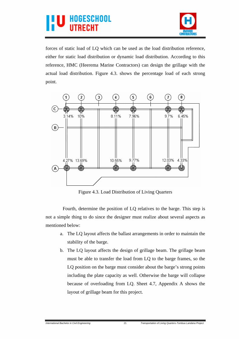
Third, calculate the load distribution from the LQ to its strong point. It is
determined by DEC as the consultant and contractor of LQ. DEC sent the detail
International Bachelor in Civil Engineering 21 Transportation of Living Quarters-Tombua Landana Project
forces of static load of LQ which can be used as the load distribution reference,
either for static load distribution or dynamic load distribution. According to this
reference, HMC (Heerema Marine Contractors) can design the grillage with the
actual load distribution. Figure 4.3. shows the percentage load of each strong
point.
Figure 4.3. Load Distribution of Living Quarters
Fourth, determine the position of LQ relatives to the barge. This step is
not a simple thing to do since the designer must realize about several aspects as
mentioned below:
a. The LQ layout affects the ballast arrangements in order to maintain the
stability of the barge.
b. The LQ layout affects the design of grillage beam. The grillage beam
must be able to transfer the load from LQ to the barge frames, so the
LQ position on the barge must consider about the barge’s strong points
including the plate capacity as well. Otherwise the barge will collapse
because of overloading from LQ. Sheet 4.7, Appendix A shows the
layout of grillage beam for this project.

International Bachelor in Civil Engineering 22 Transportation of Living Quarters-Tombua Landana Project
c. Related to point “b”, the grillage beam also influences the load-out
process. Especially when the load-out process uses the trailer to
transport the LQ onto the barge. The grillage beam configuration must
give sufficient free space between grillage and the trailer wheels. The
minimum required free space is 1ft (3.048m). The grillage layout is
shown in Figure 4.4. and for more information about relation between
LQ grillage beam layout and the trailer is shown in Figure 5.6. and
appendix B.
Figure 4.4. Grillage Beam Layout
Fifth, calculate the actual forces. There are two kinds of loads, static and
dynamic load. Static loads state for the dead load while LQ is loaded onto the
barge. Dynamic loads occur when the loaded barge is sailing. The dynamic load is
influenced by barge motions, such as heave, roll, and pitch. Actually, dynamic
loads are complicated loads, since the position of LQ relatives to the barge has
affects as well. See Figure 4.5. for roll to starboard forces and Figure 4.6. for pitch
to bow forces. The complete calculation is shown in Appendix B.

International Bachelor in Civil Engineering 23 Transportation of Living Quarters-Tombua Landana Project
Figure 4.5. Roll to Starboard Forces
Figure 4.6. Pitch to Bow Forces
Sixth, design the grillage beam. As mentioned before, the grillage beam
must transfer the LQ load to the strong points of barge. There are some strong
points of the barge; they are:
a. intersection between longitudinal bulkhead and transverse bulkhead
b. intersection between rail girder and transverse bulkhead
c. intersection between longitudinal bulkhead and transverse web frame
d. intersection between rail girder and transverse web frame
e. Side shell
Every strong point has its own capacity and has to govern the transferred load
from grillage support. When the barge capacity is not strong enough, the designer
has to redesign the grillage beam. It can change of the grillage beam location or
the configuration of the grillage beam itself.
Seventh, check the grillage beam capacity. Checking is always needed to
be done in order to ensure that the construction is strong enough. This kind of
checking is about strength checking of the grillage beam profile that is compared

International Bachelor in Civil Engineering 24 Transportation of Living Quarters-Tombua Landana Project
to the allowable stress. The ratio between occurred stress and allowable stress
according to AISC (American Institute of Steel Construction) is called Unity
Check (U.C.). The U.C. must be less than 1. The formula as follows:
The occurred stress is: 2//
2 ττσ += ⊥c
The allowable stresses according to AISC code are:
a. Axial compression : 0.60 Fy (N/mm2)
b. Axial tension : 0.60 Fy (N/mm2)
c. Shear : 0.40 Fy (N/mm2)
d. Bending : 0.66 Fy (N/mm2)
e. Combined : 0.66 Fy (N/mm2)
Eighth, design the wing plate, end stiffener, and welding details for the
grillage beam.
4.1.1.1. Wing Plate
The grillage beams end on the rail girders and the longitudinal bulkheads.
There are two possibilities of the end of the grillage beam, whether it will use
wing plate or end stiffener. Before deciding to use wing plate or end stiffener, the
capacity of the longitudinal bulkhead and rail girder must be compare to the
reaction force of the grillage beam first. If the capacity less than the vertical
reaction, wing plate must be attached in the end of the grillage beam. In the other
words if the capacity more than the vertical reaction, it is only need end stiffener.
The wing plate (Figure 4.7.) is attached on the bulkhead or web frame.
The main purpose of the wing plate is for spreading the vertical reaction of a
grillage beam to the bulkhead plate or web frame and giving the resistance
through the uplift dynamic force. Since the wing plate stands on the plate, the
designer has to consider the frame profile underneath the wing plate and its weld
size. Designing wing plate which stands on massive plate such as longitudinal

International Bachelor in Civil Engineering 25 Transportation of Living Quarters-Tombua Landana Project
bulkhead is different when it stands on the rail girder beams, though they have to
hold the same vertical reaction.
Figure 4.7. Wing Plate
There are several factors that must be taken into account while
calculating the wing plate, such as:
a. Dimensions of the shim plate. The wider it is the effective area of the
wing plate becomes less.
b. The throat size of the weld, both weld to web and weld to barge deck.
c. Grillage beam profile since the wing plate is attached from the deck till
the top flange of grillage beam. In the other hand, the width of wing
plate is influenced by shim plate width and the vertical reaction.
d. Plate buckling. The buckling capacity check must be done by engineer
to make sure that wing plate will not collapse due to buckling forces
through the plate thickness.
For more detailed calculation and the cross section of the wing plate, see
sheet 4.29-43, Appendix A. The design of the wing plate is not based only on the
reaction force but also on the uplift dynamic force. The weld resistance
underneath the deck has to be checked against the uplift dynamic force (sheet
4.44-45, Appendix A). The purpose of this checking is to ensure that the welding
underneath the deck is strong enough. In some cases, while the uplift force is

International Bachelor in Civil Engineering 26 Transportation of Living Quarters-Tombua Landana Project
occurred in the end stiffener, the welding underneath the deck cannot hold it. It
means in that place, the wing plate must be attached to against the uplift force so
the grillage beam still stands with a proper connection to the deck.
Wing plate can be attached in two ways, depends on how much free
space between wing plate and trailer wheels is available. First, when the sufficient
free space is available, the wing plate can be attached before load-out. It means
that the wing plate attachment is done during grillage preparation. Second when
the required minimum free space is unavailable, the wing plate will be attached
after load-out. It means, during load-out, the grillage beam only has end stiffener
to spread the vertical static load. More information about the end stiffener is
explained in the next paragraph.
For this project, wing plate will be attached in the end of grillage
beam on the longitudinal bulkhead because its capacity is less than the vertical
reaction of the grillage beam. Wing plate will be attached in the end of grillage
beams except for detail A and E (sheet 4.29 and 4.42, Appendix A).
4.1.1.2. End stiffeners
It has already stated before that if the capacity of the longitudinal
bulkhead or rail girder more than the vertical reaction, only end stiffener is needed
(Figure 4.8.). For this project, end stiffeners will be attached in the end of the
grillage beam for detail A and E (sheet 4.29 and 4.42, Appendix A). Its vertical
reaction is less than the capacity of the longitudinal bulkhead and the rail girder.

International Bachelor in Civil Engineering 27 Transportation of Living Quarters-Tombua Landana Project
Figure 4.8. End Stiffener
Not likely wing plate that functions to spread the vertical reaction, end
stiffener functions to prevent web buckling, maintain the shape of the beam and
its rigidity. That is why it is still needed to attached end stiffener although the
unity check is less than 1.
4.1.1.3. Welds
Welding is one of the most common methods that are used for joining
two steel sections. In this project, the welding procedure including the allowable
stresses is based on American Welding Society (AWS) structural welding code.
There are many types of welds, such as groove welds, fillet welds, plug welds, etc.
It will use fillet weld as shown in Figure 4.9. There are many types of welds, such
as groove welds, fillet welds, plug welds, etc. In this case, fillet welds will be
used. When calculating the strength of fillet welds, the throat size should be used
since it is a critical part of the welds. The welds will also be treated as if it is a
perfect triangle.

International Bachelor in Civil Engineering 28 Transportation of Living Quarters-Tombua Landana Project
Figure 4.9. Fillet Weld
There is the minimum value for weld which depends on the thicker plate
to be joined (Table 4.1.) and the maximum value depends on the thinner plate to
be joined. These values are based on AWS.
Table 4.1. Fillet Weld Minimum Size (AWS)
Thickness of thicker Minimum leg size plate to be joined of fillet weld*
thru 1/2 in 3/16 in over 1/2 in thru 3/4 in 1/4 in
over 3/4 in thru 11/2 in 5/16 in over 11/2 in thru 21/4 in 3/8 in over 21/4 in thru 6 in 1/2 in
over 6 in 5/8 in * Do not need exceed the thickness of the thinner plate
There are many different parts that need to be joined by welding as
mentioned below:
1. Welds between the flange and the web of grillage beam
2. Welds between two grillage beams
3. Welds between stiffeners and the web of grillage beam
4. Welds between wing plate and the web of grillage beam

International Bachelor in Civil Engineering 29 Transportation of Living Quarters-Tombua Landana Project
5. Welds between wing plate and the deck of the barge
6. Welds between seafastening and the plate which is attached to the LQ
beam
7. Welds between seafastening and the plate which is attached to the
seafastening beam
Grillage beam is a plate girder so it is needed to join the flange and the
web. The length of this weld is continuous along the beam. The connection
between two grillage beams is welded on both sides of the web. In this case, the
top flanges of these two beams are level. It make the welds can be designed as
simple as possible. Because of the throat size needed for all welds under the
minimum value, all the throat size of the welds can be made the same. Moreover,
it can make the execution easier. The throat size is 13.5mm which is based on the
minimum value while the leg size is 19.05mm. The detail calculation can be seen
in sheet 4.28, Appendix A.
Ninth, check the barge capacity. There are couples of checks for barge
capacity, depend on where the grillage beam ends. First, check the capacity of the
bulkhead columns. The reactions of the grillage beam must be less than the
capacity of the bulkhead columns. Second, check the capacity of the plates below
the grillage beam whether they are strong enough to hold all the reaction forces
from the grillage beams or not. If the grillage beam ends at rail girder, the capacity
of the rail girder itself must be checked.
4.1.2. Grillage Calculations
See sheet 4.1-4.76, Appendix A.
4.2. Seafastening
Seafastening is defined as steelwork installed after load-out to restrain
the cargo for horizontal roll and pitch forces. It is a temporary structure which
made from tubular steel tube (Fe 510, Fy = 345N/mm2). It will be removed after
arrived at installation site so it is designed for ease of fitting and removal.

International Bachelor in Civil Engineering 30 Transportation of Living Quarters-Tombua Landana Project
4.2.1 Seafastening Concept Design
Seafastening should be located under the LQ strong columns in order to
get optimum load distribution. Moreover, it can prevent the LQ beam from
deflection. The seafastening layout is shown in Figure 4.10 and sheet 4.11,
Appendix A. The length depends on the web frame spacing. The minimum angle
of the seafastening is 20°. If the angle is less than 20°, the construction process
will more difficult. The welder needs a certain sufficient space for doing welding
and attaching to the roll brace.
Figure 4.10. Seafastening Layout
There are two kinds of seafastening, transverse seafastening (roll brace)
and longitudinal seafastening (pitch stopper) (Figure 4.11. and Figure 4.12.).
Transverse seafastening will hold the horizontal force in starboard-portside
direction which is caused by pitch motion while longitudinal seafastening will
hold the horizontal force in bow-stern direction which is caused by roll motion.
Transverse seafastening uses 10.75in of tubular steel pipe while the longitudinal
seafastening uses 12in of tubular steel pipe.

International Bachelor in Civil Engineering 31 Transportation of Living Quarters-Tombua Landana Project
Figure 4.11. Roll Brace
Figure 4.12. Pitch Stopper
The concept design of seafastening is almost the same with the grillage
concept design. The load from LQ will be transferred through the seafastening roll
brace and then transferred to seafastening beam. Then the vertical load is
transferred to the strong point of barge. The vertical reaction from seafastening
beams must be less than the capacity of the local barge frame. If the capacity less
than the vertical reaction, the seafastening can be extended until get better load

International Bachelor in Civil Engineering 32 Transportation of Living Quarters-Tombua Landana Project
distribution. The other way that can be done is to attach more seafastening which
will increase the cost of course because it will cause more work for removal.
4.2.2. Seafastening Calculations
See sheet 4.77-4.95, Appendix A.
4.3. Barge Capacity Checks
The barge should have adequate size and strength to ensure that it can
hold all reaction forces caused by static and dynamic loads. There are many kinds
of barge capacity checks that should be done, such as local capacity check
(bulkhead column capacity check), web frame capacity check (plating capacity
check), and rail girder capacity check.
4.3.1. Local Capacity Check
Local capacity check is the checking in the bulkhead columns of the
barge. The checking uses ‘Bulkhead Column Capacity‘ spreadsheet which
determines the maximum allowable load on the bulkhead column. Parameters to
be entered are barge specifications and frame properties. Then the result is
compared to the vertical reaction caused by the vertical load. The reaction forces
must be less than the bulkhead column capacities. If the vertical reaction is more
than the bulkhead column capacity, the shim plate can be move a little bit in order
to get better load distribution. The other way that can be done is by adding more
LQ strong columns so the vertical reaction will be less.
Figure 4.13. shows the illustration of load distribution from strong points
of LQ to the strong points of the barge (bulkhead columns). It can be seen that the
ends of the grillage beam locate on different plates of the barge, on row 2 and row
3. The bulkhead column capacities in row 2 and row 3 are different. The capacity
in row 2 is less than row 3 (sheet 5.7, Appendix A).

International Bachelor in Civil Engineering 33 Transportation of Living Quarters-Tombua Landana Project
Figure 4.13. Concept of Load Distribution
4.3.2. Web Frame Capacity Check
Not only the bulkhead columns, but also web frame must be checked. It
must be checked for its plating capacity which is got from the ‘Plating Capacity’
spreadsheet (sheet 4.100, Appendix A). It determines the maximum allowable
load on plate under compression. Then the result is compared with the vertical
reaction of the grillage beam. Parameters to be input are the plate’s support type
and plate specifications.
4.3.3. Rail Girder Capacity Check
In spite of longitudinal bulkhead, the barge also has rail girder in the
longitudinal direction. The barge is equipped with rail girder. which functions as a
track for the crane. If the support of grillage beam is located on the rail girder, its
capacity must be checked (sheet 4.42, Appendix A). It must be ensured that the
rail girder will not collapse due to overloading of the vertical reaction from the
grillage beam. The rail girder is a 24x12” profile which made by cutting the
36WF160 profile (Figure 4.14.).

International Bachelor in Civil Engineering 34 Transportation of Living Quarters-Tombua Landana Project
Figure 4.14. Typical Rail Girder
Since it is a honey-comb profile (Figure 4.15.), it has only 10in of
effective width with 235 N/mm2, so the rail girder capacity check will be done as
below:
Figure 4.15. Rail Girder
wyeff xtFxF 6.0254=
In which:
Fy = 235 N/mm2
tw = 16.5mm

International Bachelor in Civil Engineering 35 Transportation of Living Quarters-Tombua Landana Project
kNF
NF
mmxmmNxmmxF
eff
eff
eff
591590931
5.16/2356.0254 2
=
=
=
For grillage beam ends on rail girder, instead of longitudinal bulkhead, needs to
compare the vertical reaction force and the rail girder capacity first. In case that
the reaction force is more than rail girder capacity, it means that wing plate has to
be designed to spread the force. If the rail girder capacity already governs the
forces, it means that only end stiffener which is needed. For instance, compare
between detail D and detail C (see sheet 4.38-4.43, Appendix A).

International Bachelor in Civil Engineering 36 Transportation of Living Quarters-Tombua Landana Project
CHAPTER 5
Transportation and Installation Phase
5.1. Transportation Phase
Heerema Marine Contractors (HMC) is responsible for the transportation
of living quarters (LQ) from hand-over until arriving at the installation site. The
transportation phases are defined into three mains steps. They are load-out phase,
sailing phase, and installation phase. Each phase has detailed compulsory
activities. For that reason HMC needs to determine the necessary activities in each
step.
5.1.1. Load-out
Load-out means transferring cargo onto barge for transporting it to its
final location. The fabricator, Delta Engineering Corporation (DEC), is
responsible for this phase. HMC only stands as the witness, to check and proof
that everything is in good condition. There are two kinds of load-out:
By skidding (Figure 5.1.)
Push and pull strand jacks (skidding by pull-push method, using cable strand
jacks to pull on to the transport barge).
Figure 5.1. Skid Beam

International Bachelor in Civil Engineering 37 Transportation of Living Quarters-Tombua Landana Project
Using trailers (Figure 5.2.)
Use a mobile train of self-powered skid with continuous support of
pneumatic tires, roll onto the barge.
Figure 5.2. Trailers Moving a Module
In fact, the load-out process is a complex process. Therefore, there are
pre load-out activities which are done before the cargo was moved onto the barge.
Here are some of the activities:
1. General check
Covering the visually check of LQ and obtain the weight report.
2. Lift points check
Doing the general review of the lift points completion according to
as-built drawing and checking them which may damage slings.
3. Installation of main lift rigging
The main purpose of this step is to ensure that slings can be
connected to padeyes without any obstacles during the process.
Several things that must be done are:
a. check slings to avoid the damage,
b. check slings identification marking with rigging drawings,
c. check slings are laid down according to drawing,
d. check sling tie-downs per lashing drawing,

International Bachelor in Civil Engineering 38 Transportation of Living Quarters-Tombua Landana Project
e. check no obstructions in the vicinity of lift points,
f. check if shackle safety pins are installed,
g. check no sharp edges on structure which may damage the slings,
h. check if all protective wood is in place and secured.
4. Installation aids:
a. lift points
b. protection on roof of LQ
c. safe access to lift points for sling removal
d. lift off guides
e. tugger line attachments
f. safe access to working areas
g. guides and bumper system
When a barge is loaded, it has an inclination between bow and stern. If
this inclination is too big it can lead to a failure operation. Preventing the failure,
the barge level must be kept the same as the dockside level, which means that
ballasting or de-ballasting is required. Besides ballast preparation, grillage also
has to be attached before load-out.
The LQ load-out of Tombua Landana project is done in Delta yard as
shown below (Figure 5.3.):
Figure 5.3. Delta Yard

International Bachelor in Civil Engineering 39 Transportation of Living Quarters-Tombua Landana Project
The available space in Delta yard is less than the required space of 400ft
barge. The actual condition makes the stern load-out can not be done directly.
Therefore LQ load-out will be done twice as described below:
1. Move the LQ from Delta yard to first barge which has 250ft long. It will be
done in the stern to bow direction (Figure 5.4.).
Figure 5.4. First Phase
2. Turn the first barge stern to Crowley barge stern and then move the LQ to
Crowley barge. It is also done in stern to bow direction (Figure 5.5.).
Figure 5.5. Second Phase

International Bachelor in Civil Engineering 40 Transportation of Living Quarters-Tombua Landana Project
The complete phases which are proposed by Mammoet, as the supplier of the
trailers can be seen in Appendix C.
Mammoet has a discussion with HMC during determining the most
applicable position for LQ load-out. As written in chapter 4, there is a relation
between grillages layout and the trailer’s position. The cross section of grillages
and trailer from HMC proposal is shown in Figure 5.6. When this report was
written, HMC was still waiting for the confirmation from Mammoet due to the
difference proposal of grillage-trailer layout between them.
Figure 5.6. Cross Section of Grillages and Trailer (HMC’s Proposal)
5.1.2. Sailing overseas
Since the transportation is performed through the sea, the sea parameters
must be taken into account. They influence the stability of barge and the cargo
during transportation. Maintaining barge and cargo stability needs several things
to be prepared well before. For once it sails, nothing can be done anymore. This

International Bachelor in Civil Engineering 41 Transportation of Living Quarters-Tombua Landana Project
sub-chapter describes any factors which must be designed in order to keep
everything in a safe condition.
5.1.2.1. Ballast Arrangement
The C.o.G. of the cargo is not always located at centre of gravity (C.o.G.)
of the barge. When the cargo is located onto barge which has certain weight and
centre of buoyancy, there will be an inclination between bow-stern (trim) and
portside-starboard (list) which cause instability of the barge. Therefore ballast
arrangement is needed to maintain this inclination small (slight trim). Figure 5.7.
and Figure 5.8. show the trim and the list. The other purpose of ballast
arrangement is to get certain value of draft. The required draft of Crowley-411 is
40% of the barge depth. One thing should be realized is that trim and list are
different with pitch and roll. Pitch and roll are part of barge’s motions due to sea
parameters while trim and list are adjusted angle of barge due to ballast
arrangement.
The ballast arrangement must give the optimal trim, list, and draft. It
means that the barge needs to submerge into the water to maintain its stability.
When the barge does not have sufficient draft, it tends to sway which will affect
the stability of the barge. In the other hand, when the barge has more draft, it is
more stable but the consequences are that the bollard pull will get more stress and
bigger propulsion is needed.
It will be a difference case for list. It can be imagined when the barge has
over list to starboard, for instance, both of the tug boat and the barge will tend to
move to the starboard direction. It means that the captain has to maintain the
direction line quite often otherwise the tug boat and the barge will run into circle
direction.
Figure 5.7. Trim Condition (Starboard View)

International Bachelor in Civil Engineering 42 Transportation of Living Quarters-Tombua Landana Project
Figure 5.8. List Condition (Stern View)
5.1.2.2. Bollard Pull
It has been stated before that the barge is non-propelled so a tug boat is
needed to pull it. The pulling force of a tug boat is called bollard pull. A sufficient
bollard pull is required in order to overcome the sea conditions which give loads
to the barge and the tug boat itself. Bollard pull of the towing barge should be
sufficient enough to maintain zero speed against the wind velocity, current
velocity, and other sea state parameters. The criteria, used to calculate bollard
pull, is based on Noble Denton criteria which has 20m/s of wind velocity, 0.5 m/s
of current velocity, and 5m of significant wave height (Ref. to Noble Denton
Criteria).
There are tree kinds of environmental loads on the barge and its cargo
which will be taken into account for calculating the bollard pull:
Wind load
Wind is an important environmental parameter that influences the
design of the floating offshore structure. It acts on both the cargo and barge
itself that will contribute as a load which depends on the size of the barge
and cargo (Figure 5.9.). There are different shapes of cargo being
transported by HMC such as solid box and open truss.

International Bachelor in Civil Engineering 43 Transportation of Living Quarters-Tombua Landana Project
Figure 5.9. Wind Load
To calculate the wind force, the barge and the cargo must be taken
into accounts which are considered as solid boxes. Their dimensions
influence the shape coefficient. There are several things that must be known
before determining shape coefficient (Figure 5.10.), such as:
- ratio between the greater dimension of the member and the lesser
dimension of the member (l/w),
- ratio between the dimension of the member normal to the wind and
the dimension of the member in the direction of the wind (b/d),
- ratio between the member height and the dimension of the member
normal to the wind must be known first (h/b).
Figure 5.10. Wind Direction to the Cargo
Hull resistance
The hull resistance of a ship is the resistance of a ship when it is
sailing on the water. The hull resistance is a result of the friction of the water
along the hull, the pressure distribution along the hull depending on its
shape, and the waves that are generated by the ship. The friction will be

International Bachelor in Civil Engineering 44 Transportation of Living Quarters-Tombua Landana Project
higher along with the current velocity. In this project the current velocity is
only 0.5m/s or 1.0m/s so the hull resistance is quite small and it has no
significant influence to the required bollard pull. For Crowley-411 there is a
scow at the end of the ship and the hull resistance is 0.2mT (sheet 4.110,
Appendix A).
Wave drift load
Since the transportation performs across the sea, the wave holds an
important role. It contributes the largest load to the environment loads. That
is why it is needed to calculate this load accurately. The small change in
input will cause totally different result. The slope of the bow to the water
surface is 48 degrees and from the calculation the wave resistance is 20.9mT
(sheet 4.110, Appendix A).
By sum up the wind resistance, the hull resistance, and the wave
resistance, the total towline pull required can be obtained. There is a tug efficiency
since many aspects influenced it. This efficiency depends on the required bollard
pull, the sea state parameters, and the towing speed (Table 5.1.), which is
determined by using formula as below:
Where: Te = the tug efficiency (%)
(BP x Te/100) = the contribution to the towline pull requirement
of each tug
Table 5.1. Tug Efficiency
Continuous Bollard Pull Te (%) (BP), tonnes Calm Hsig = 2m Hsig = 5m
BP ≤ 30 80 50 + BP BP 30 < BP < 90 80 80 30 + [0.75 x (BP - 30)]
BP ≥ 90 80 80 75

International Bachelor in Civil Engineering 45 Transportation of Living Quarters-Tombua Landana Project
In this case, it requires 32.62mT of TPR to pull the barge. But since the tug
efficiency is only 53.35%, the required bollard pull become 61.14mT (sheet
4.110, Appendix A).
5.1.2.3. Tug Boat
Tug boat is a boat, used to pull the non-propelled barge. The tug selection
should fulfill the minimum bollard pull requirements. The tug boat that will be
used is called “Invader” with a capacity of 150,000lbs (68mT) (Appendix D). It is
provided by Crowley Maritime Corporation.
5.1.2.4. Towing Equipments
Since the barge is pulled by a tug boat, the tug boat must be facilitated
with towing equipments. To arrange these equipments, the worst sea state
characteristics of the route should be considered. In this project, the barge which
has a wide bow is pulled from the forward end of the barge via suitable bridles.
The components of these equipments are:
Towline connections, including towline connection points, fairleads,
bridle legs, and bridle apex (Figure 5.11.)
Intermediate pennant
Bridles recovery system
Emergency towing gear (Figure 5.12.) and Appendix E

International Bachelor in Civil Engineering 46 Transportation of Living Quarters-Tombua Landana Project
Figure 5.11. Main Tow Bridle with Recovery System
Figure 5.12. Emergency Towing Gear
The towing barge should be equipped with towing winch where its
minimum breaking load (MBL) is based on the actual continuous static bollard
pull (BP) as shown in Table 5.2.

International Bachelor in Civil Engineering 47 Transportation of Living Quarters-Tombua Landana Project
Table 5.2. Towline Breaking Load (MBL)
Bollard Pull (BP) Benign Areas Other Areas BP ≤ 40 tonnes 2 x BP 3 x BP 40 < BP ≤ 90 tonnes 2 x BP (3.8 - BP/50) x BP BP > 90 tonnes 2 x BP 2 x BP
Since the routes of LQ transportation have extremes (tropical cyclone in
the Gulf of Mexico, Caribbean seas, West Indies and winter storms in the Gulf of
Mexico), the towline breaking load is computed for other areas.
MBL = (3.8 – BP/50) x BP
= (3.8 – 68/50) x 68
= 165.92 mT
There is ultimate load that the bridle can hold:
ULC = 1.25 x MBL
= 1.25 x 165.92
= 207.4 mT
ULC = MBL + 40
= 165.92 + 40
= 205.92 mT
ULC = min (207.4 ; 205.92)
= 205.92 mT
There is a certain length of towline, used to pull the barge as shown in
Figure 5.13.
Figure 5.13. Barge and Its Tug Boat
Towline length > MBLBP x 1800metres
Where: BP = Bollard pull (mT)
MBL = Minimum Breaking Load (mT)

International Bachelor in Civil Engineering 48 Transportation of Living Quarters-Tombua Landana Project
Towline length = BP/MBL x 1800 m
= 68/205.92 x 1800 m
= 594.41 m
In case of towline failure, an emergency towing gear should be provided
to recover the bridle. This equipment is preferably located at the bow of the barge
and should consist of a spare bridle or towing pennant, fitted with a floating rope
and buoy, allowing it to be picked up without any difficulties. The other way to
cope with towline failure is by providing at least one anchor. It is attached to a
chain cable or wire, which is arranged for release manually.
5.2. Installation Phase
LQ installation (Figure 5.14.) is done in second phase of installation. The
second phase is scheduled to be accomplished in the end of December 2008. The
Thialf takes the installation for the Tombua Landana project. The installation use
only single crane, for the one Thialf crane’s capacity (7000mT) is already
sufficient for the weight of LQ (1622mT). For the LQ installation, there are three
main activities, they are pre-installation, installation and post installation. Since
there are plenty of detailed steps, it is decided that only the main steps will be
described in this final thesis report.
1. Pre-installation activities
a. Pre-lift activities on Thialf
Consist of preparation for fender, mooring and tugger lines.
b. Pre-installation activities on top sides platform
c. Pre-lift activities on Crowley 411
Confirm if Crowley 411 is ready to commence installation
operations and safe to enter
d. Pre-lift activities on tugboats
e. Pre-lift activities on LQ
Need to check the condition in LQ to be sure that LQ is clear of
any items that can obstruct installation.

International Bachelor in Civil Engineering 49 Transportation of Living Quarters-Tombua Landana Project
2. Installation activities
a. move the barge to its position according to the drawing
installation
b. check the environmental conditions, such as wind and waves
c. check the rigging layout according to the drawing (sheet 1,
Appendix F)
d. cut LQ seafastenings
e. attach tugger lines / steering lines
f. lift-off LQ
g. Install LQ
h. Transfer personnel to the platform in order to monitor operations
and for de-rigging.
3. Post-installation activities
a. release shackles, remove slings and transfer to SSCV deck
b. Helideck completion
c. Removal of LQ rotation wire guides
d. Remove padeyes
e. Remove guides and bumpers
f. Demobilize personnel back to the SSCV
g. Move-out SSCV and sail to another project location.

International Bachelor in Civil Engineering 50 Transportation of Living Quarters-Tombua Landana Project
Figure 5.14. Living Quarters Installation

International Bachelor in Civil Engineering 51 Transportation of Living Quarters-Tombua Landana Project
CHAPTER 6
Conclusions and Suggestions
6.1. Conclusions
Transportation of offshore oil platform is influenced by the sea
parameters, such as wave, wind, and current in the sea. They have significant
influences to the transportation of the platform. Therefore it is needed steel
structures to secure the platform during the transportation. For this project, the
platform which is transported is Living Quarters. To transport it, six grillages are
needed, eight roll braces as transverse seafastenings, and two pitch stoppers as
longitudinal seafastenings.
There are six grillage beams which function to withstand all the vertical
force caused by static and dynamic loads. Each of the grillage beam has 20ft long.
It is a parallel beam which consists of three PG 190x1524x38x25.4 and two PG
380x1524x38x28.58. The connection between each beam uses fillet weld with leg
size of 19.05mm. The wing plates and the end stiffeners are attached in the end of
the grillage beams in order to spread the load and to maintain the rigidity of the
beam itself. To withstand all the horizontal forces caused by static and dynamic
loads, seafastenings are needed. The roll braces are 10.75in diameter of tube steel
and attached from Living Quarters beam to the barge deck. The pitch stoppers are
plate with 1in. thick which is connected to Living Quarter’s beam and grillage
beam.
Since the barge is not self-propelled, it needs a tug boat to pull it by using
61.14mT of bollard pull. The tug boat which will use for this project is called
“Invader” tug boat which is provided by Crowley as the provider of the barge as
well.

International Bachelor in Civil Engineering 52 Transportation of Living Quarters-Tombua Landana Project
6.2. Suggestions
1. The Moses analysis for knowing the dynamic forces during transportation
must be done, instead of using Noble Denton criteria.
2. It is better to have a 3D model which contents cargo, grillage,
seafastening, and barge in one model. Although it takes time to develop a
3D model, it gives more accurate results for the design.
3. Organizing some courses for the internship students will make the learning
process goes faster.
4. Choosing the unit system, Imperial or Metric in the preliminary design
will be better, especially when designing for the American client.

International Bachelor in Civil Engineering 53 Transportation of Living Quarters-Tombua Landana Project
REFERENCES
Straathof, A. Offshore Technology: Introduction Courses for the T&I ‘Junior’
Engineer. Netherlands: Heerema Marine Contractors (HMC).
Blodgett, Omer W. (1966, June). Design of Welded Structures. Cleveland, Ohio:
The James F. Lincoln Arc Welding Foundation.
Standard Symbols for Welding, Brazing, and Nondestructive Examination.
Miami, Florida: American welding Society (AWS).
Table Profile. Netherlands: Heerema Marine Contractors (HMC).
Standard Criteria. Netherlands: Heerema Marine Contractors (HMC).
www.hmc-insite.com (HMC Intranet)
www.wikipedia.org

International Bachelor in Civil Engineering 54 Transportation of Living Quarters-Tombua Landana Project
LIST OF FORMULAS
1. Plate Girder Properties ............................................................................ 55
2. Transportation Forces ............................................................................. 59
3. Plating Capacity ...................................................................................... 63
4. Bollard Pull .............................................................................................. 66
Source: HMC’s IPEX Manual

International Bachelor in Civil Engineering 55 Transportation of Living Quarters-Tombua Landana Project
1. PLATE GIRDER PROPERTIES The spreadsheet 'PLATE GIRDER PROPERTIES' calculates the section properties of plate girders built-up from a maximum of 15 sections. The calculated section properties are equivalent to the SACS nomenclature. Different units for input and output can be selected, allowing for automatic unit conversion. Validity of the spreadsheet The spreadsheet is only valid for open plate girders, with no more than one web in any horizontal cross-section. A web is defined as a part with a larger height (Z) than breadth (Y), a flange is defined as a part with a height equal or smaller than the breadth. Sections that can be entered:
Please note that the spreadsheet has the following imperfections:
Flanges should not protrude beyond the widest flange. The widest flange should not be given an offset ey. Plate sections should be stacked on top of each other. The Az shear area is calculated using the mean web thickness at the intersection with the flanges.
Sections that CAN NOT be entered:
Input: entering sections and co-ordinate system. The origin of the co-ordinate system used by the spreadsheet is positioned at the bottom of the plate girder at the centre line of the widest flange. Sections (webs

International Bachelor in Civil Engineering 56 Transportation of Living Quarters-Tombua Landana Project
and flanges) of the plate girder should be entered from top to bottom. The spreadsheet will stack each successive section below its predecessor and shift the co-ordinate origin to the bottom of the last section, in the centre of the web or flange with the largest breadth. See figure below. Sections with a C.o.G not on the Z-axis can be offset by entering the positive or negative distance, ey, towards the Z-axis, i.e. the distance between the C.o.G's of the subject section and the widest one. Therefore, the widest section should not be given an offset.
Unit conversion Plate girder properties can be entered and calculated in several units; Millimetres, centimetres, meters and inches. The plate girder weight per length can be calculated in kN/m, kg/m, mT/m, lb/ft, lb/inch and lb/yard. When different input and output units are selected the spreadsheet will automatically make the proper conversion. Selecting the units is done by clicking once on the appropriate button from one of the menus (Input, Output and Weight) situated on the right hand side of the spreadsheet. Output and calculations The output properties are with respect to Y-Z coordinates parallel to the input axes but with their origin at the plate girder C.o.G. (See figure below.) This co-ordinate system is identical to that of SACS-IV. Also the calculated properties are conform the SACS-IV nomenclature.
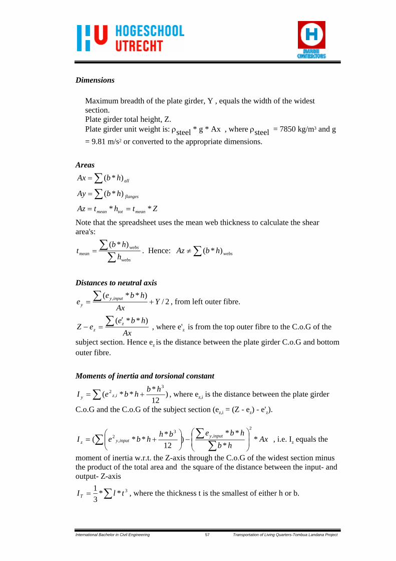
International Bachelor in Civil Engineering 57 Transportation of Living Quarters-Tombua Landana Project
Dimensions
Maximum breadth of the plate girder, Y , equals the width of the widest section. Plate girder total height, Z. Plate girder unit weight is: ρsteel * g * Ax , where ρsteel = 7850 kg/m3 and g = 9.81 m/s2 or converted to the appropriate dimensions.
Areas
∑= allhbAx )*(
∑= flangeshbAy )*(
ZthtAz meantotmean ** ==
Note that the spreadsheet uses the mean web thickness to calculate the shear area's:
∑∑=
webs
websmean h
hbt
)*(. Hence: ∑≠ webshbAz )*(
Distances to neutral axis
2/)**( , Y
Axhbe
e inputyy += ∑ , from left outer fibre.
Axhbe
eZ zz∑ ′
=−)**(
, where e'z is from the top outer fibre to the C.o.G of the
subject section. Hence ez is the distance between the plate girder C.o.G and bottom outer fibre. Moments of inertia and torsional constant
∑ += )12***(
3
,2 hbhbeI izy , where ez,i is the distance between the plate girder
C.o.G and the C.o.G of the subject section (ez,i = (Z - ez) - e'z).
Axhb
hbebhhbeI inputyinputyz *
***
)12***(
2
,3
,2
⎟⎟⎠
⎞⎜⎜⎝
⎛−⎟⎟
⎠
⎞⎜⎜⎝
⎛+=
∑∑∑ , i.e. Iz equals the
moment of inertia w.r.t. the Z-axis through the C.o.G of the widest section minus the product of the total area and the square of the distance between the input- and output- Z-axis
∑= 3**31 tlIT , where the thickness t is the smallest of either h or b.
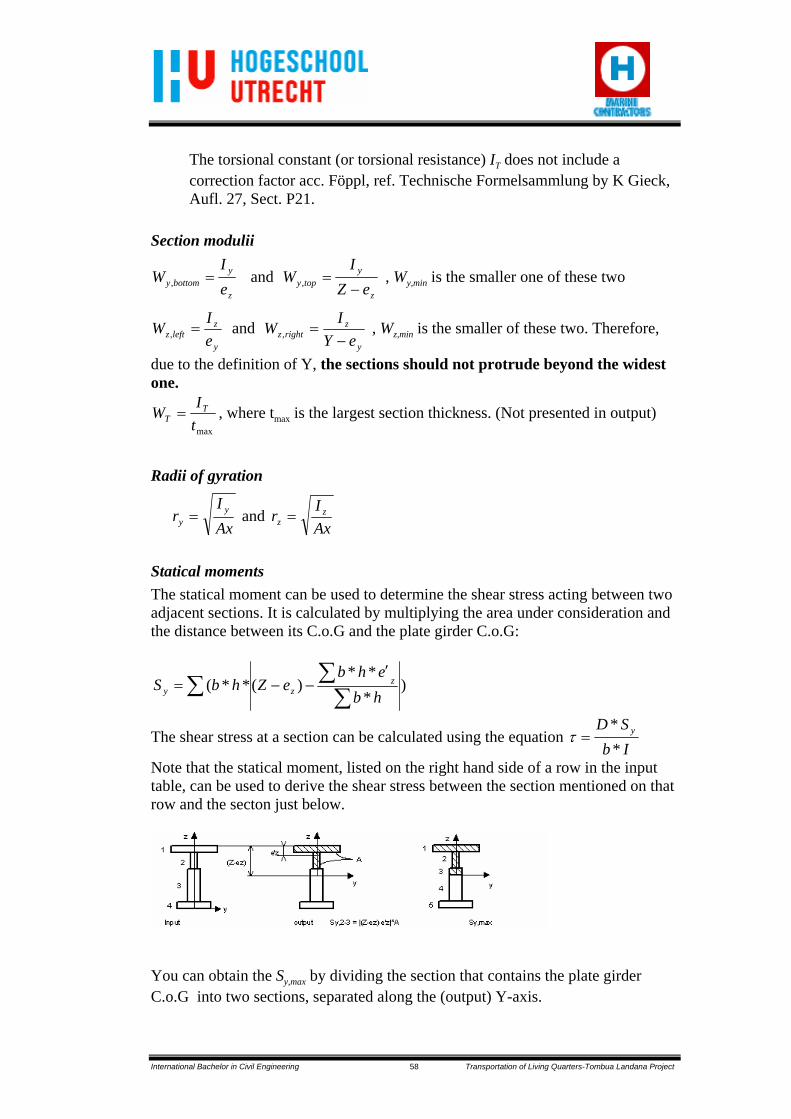
International Bachelor in Civil Engineering 58 Transportation of Living Quarters-Tombua Landana Project
The torsional constant (or torsional resistance) IT does not include a correction factor acc. Föppl, ref. Technische Formelsammlung by K Gieck, Aufl. 27, Sect. P21.
Section modulii
z
ybottomy e
IW =, and
z
ytopy eZ
IW
−=, , Wy,min is the smaller one of these two
y
zleftz e
IW =, and y
zrightz eY
IW−
=, , Wz,min is the smaller of these two. Therefore,
due to the definition of Y, the sections should not protrude beyond the widest one.
maxtI
W TT = , where tmax is the largest section thickness. (Not presented in output)
Radii of gyration
AxI
r yy = and
AxI
r zz =
Statical moments The statical moment can be used to determine the shear stress acting between two adjacent sections. It is calculated by multiplying the area under consideration and the distance between its C.o.G and the plate girder C.o.G:
)***
)(**(∑
∑∑′
−−=hbehb
eZhbS zzy
The shear stress at a section can be calculated using the equation IbSD y
**
=τ
Note that the statical moment, listed on the right hand side of a row in the input table, can be used to derive the shear stress between the section mentioned on that row and the secton just below.
You can obtain the Sy,max by dividing the section that contains the plate girder C.o.G into two sections, separated along the (output) Y-axis.

International Bachelor in Civil Engineering 59 Transportation of Living Quarters-Tombua Landana Project
2. TRANSPORTATION FORCES The spreadsheet 'TRANSPORTATION FORCES' calculates the static and dynamic transportation forces and accelerations. Parameters to be entered are transportation criteria, cargo specifications and barge or ship information. Input and output of the spreadsheet are consistent with the Bartran axis system. Angles and moments, however, are according to the Right Hand Rule!
Transportation criteria Input: The single amplitude angle for roll, θroll in degrees. The full cycle period for roll, Troll in seconds. The single amplitude for pitch, θpitch in degrees. The full cycle period for pitch, Tpitch in seconds. The single amplitude for heave, Aheave in meters. The full cycle period for heave, Theave in meters. The spreadsheet will automatically detect the Noble Denton criteria ('General guidelines for marine transportations' 0014/NDI/JR - dec. 1986, section 5.2.1) and will prompt so on the sheet. Noble Denton Criteria are: Single amplitude
(10 sec full cycle period) Type Roll Pitch Heave Small barges 25° 15° 5 m Larger barges 20° 12.5° 5 m Small vessels 30° 15° 5 m Note that the 5 m heave at a 10 sec. cycle period accounts for a vertical accelerations of 0.2 g.

International Bachelor in Civil Engineering 60 Transportation of Living Quarters-Tombua Landana Project
Cargo specifications A suitable name for the cargo can be entered for reference purposes. Input:
The weight of the cargo, W in kN. The mass moment of inertia about the roll axis, MoIx in Tm2. The mass moment of inertia about the pitch axis, MoIy in Tm2. The x - co-ordinate of the cargo centre of gravity, xCoG in m. The y - co-ordinate of the cargo centre of gravity, yCoG in m. The z - co-ordinate of the cargo centre of gravity, zCoG in m.
Barge / ship information The name or description of the barge / ship can be entered for reference purposes. Input:
The x - co-ordinate of the centre of rotation, xCoR in m. (Usually xCoR is a few meter shorter than half the barge length) The centre of rotation is on the waterlevel: zCoR = meandraft in m.
Note that by default the centre of rotation in y - direction is at half breadth of the barge. Transportation forces and accelerations The calculated transportation forces and accelerations are a combination of dynamic forces and static forces on the centre of gravity of the cargo. The spreadsheet calculates the vertical force, the horizontal force, the moments and the heave in the centre of gravity of the cargo. These forces and moment are calculated for roll to starboard and portside, and pitch to stern and bow. Note: the output forces are exerted by the module on the barge, their workpoint is the module C.o.G. An example is given below for roll to starboard, roll to portside and pitch are calculated in a similar fashion. Shown is the stern of a barge with cargo:

International Bachelor in Civil Engineering 61 Transportation of Living Quarters-Tombua Landana Project
Roll Static forces: )cos(*, rollstatic WF θν −= kN )sin(*, rollstatich WF θ−= kN
Dynamic forces: ⎟⎟
⎠
⎞
⎜⎜
⎝
⎛⎟⎟⎠
⎞⎜⎜⎝
⎛=
2
,2***
81.9 rollrollCoGdynamicv T
yWF πθ kN
⎟⎟
⎠
⎞
⎜⎜
⎝
⎛⎟⎟⎠
⎞⎜⎜⎝
⎛−−=
2
,2**)(*
81.9 rollrollCoRCoGdynamich T
zzWF πθ kN
⎟⎟
⎠
⎞
⎜⎜
⎝
⎛⎟⎟⎠
⎞⎜⎜⎝
⎛=
22**
rollrollxoroll T
IMM πθ kNm
⎟⎟
⎠
⎞
⎜⎜
⎝
⎛⎟⎟⎠
⎞⎜⎜⎝
⎛=
22**
81.9 heaveheaveroll T
AWH π kN
Combined forces: dynamicvstaticvSBv FFF ,,, += kN dynamichstatichSBh FFF ,,, += kN Pitch Below the forces acting at a module, and exerted on the barge, are shown for pitch to bow:
Static forces: )cos(*, pitchstaticv WF θ−= kN )sin(*, pitchstatich WF θ= kN

International Bachelor in Civil Engineering 62 Transportation of Living Quarters-Tombua Landana Project
Dynamic forces: ⎟⎟
⎠
⎞
⎜⎜
⎝
⎛
⎟⎟⎠
⎞⎜⎜⎝
⎛−−=
2
,2**)(*
81.9 pitchpitchCoRCoGdynamicv T
xxWF πθ kN
⎟⎟
⎠
⎞
⎜⎜
⎝
⎛
⎟⎟⎠
⎞⎜⎜⎝
⎛−=
2
,2**)(*
81.9 pitchpitchCoRCoGdynamich T
zzWF πθ kN
⎟⎟
⎠
⎞
⎜⎜
⎝
⎛
⎟⎟⎠
⎞⎜⎜⎝
⎛=
22**pitch
pitchyopitch TIMM πθ kNm
⎟⎟
⎠
⎞
⎜⎜
⎝
⎛⎟⎟⎠
⎞⎜⎜⎝
⎛=
22**
81.9 heaveheavepitch T
AWH π kN
Combined forces: dynamicvstaticvsternv FFF ,,, += kN dynamichstatichsternh FFF ,,, += kN

International Bachelor in Civil Engineering 63 Transportation of Living Quarters-Tombua Landana Project
3. PLATING CAPACITY
The spreadsheet ‘PLATING CAPACITY’ calculates the maximum allowable load on plates under compression. The critical buckling stress due to compression is based on the Priest – Gilligan curve as described in O.W. Blodgett’s ‘Design of welded structures’, June 1966. Buckling resistance of plates under linear compression The spreadsheet calculates the buckling resistance for plates supported in several ways. A selection box with various support types is placed on the right side of the spreadsheet. By default the ‘four sides supported’ loadcase is selected. Implemented support types are:
Depending on the support type, the following plate factor is used: 1. One side supported, one side free: k = 0.425 2. One side fixed, one side free: k = 1.277 3. Two sides supported: k = 4 4. One side supported, one side fixed: k = 5.42 5. Two sides fixed: k = 6.97 6. Four sides supported: k = 4 for α ≥1.0. For α ≤ 1.0: 2)/1( αα +=k Input: • Modulus of elasticity, default value is 25 /10*1.2 mmNE = • Poisson’s ratio, default value is ν = 0.3. • Thickness of the plate, t in mm. • Length of the plate, a in mm. • Width of the plate, b in mm. (Loaded side). (α = a/b) • Yield stress, yσ in 2/ mmN .
Supported Fixed
Fixed
Fixed
Supported
Supported Free Free
Supported Fixed Supported
Supported
1 2 3
4 5 6

International Bachelor in Civil Engineering 64 Transportation of Living Quarters-Tombua Landana Project
Calculation: • The critical stress determination is based on the Priest – Gilligan curve as can be found on
sheet 2.12-6 of ‘Design of Welded Structures’ by Omar W. Blodgett. This is done by determining the points B and C of the curve and selecting the proper portion of the curve.
Point B is found at a yk
tbσ
3820/= , where yσ is entered in pound per square inch (psi).
Point C is found at a yk
tbσ
5720/= , yσ in psi.
By comparing the calculated factor and the factors for points B and C the proper portion of the curve is selected.
• Using the selected portion the critical stress can be calculated:
For the portion A – B: ,ycr σσ = in 2/ mmN .
For the portion B – C: ktby
ycr/*
47708.1
3σσσ −= , where crσ and yσ are in psi.
For the portion C - D: 2
2
2
*)1(*12
***75.0 ⎟⎠⎞
⎜⎝⎛
−=
btEk
cr νπσ in N/mm2.
• At the calculated critical stress the middle portion of the plate would be expected to buckle.
However, the over-all plate will not collapse since the portion of the plate along the supported sides could still be loaded up to the yield point before ultimate collapse. This portion of the plate, the ‘effective width’, can be determined by finding the ratio b/t at the point where
ycr σσ = , point B of the Priest – Gilligan curve. The plate factor k is limited to a maximum
of 4, i.e. a two sides supported plate or a four sides supported plate with a ≥ b:
kt
b
y
eff *3820σ
= , yσ in psi.
• The effective width is calculated by multiplying the factor tbeff / by the plate thickness. • The maximum allowable load for the plate is:
{ }creffyeff tbbtbF σσ *6.0**)()*6.0(** −+= *10-3 in kN. (0.6 to account for allowable stresses according to AISC)
The maximum specific allowable load is F/b in kN/m.

International Bachelor in Civil Engineering 65 Transportation of Living Quarters-Tombua Landana Project
Output: • The critical stress, and the portion of the Priest – Gilligan curve that is used. • The k-factor depending on the type of support and plate shape factor ba /=α . • The effective width effb in mm.
• The maximum allowable load F in kN. • The maximum allowable specific load in kN/m.

International Bachelor in Civil Engineering 66 Transportation of Living Quarters-Tombua Landana Project
4. BOLLARD PULL
Wind Load
γρ CCCA
z
VF tsawind ××××
⎥⎥⎥⎥
⎦
⎤
⎢⎢⎢⎢
⎣
⎡
⎟⎠⎞
⎜⎝⎛−
⎟⎠⎞
⎜⎝⎛−⎟
⎠⎞
⎜⎝⎛+
=
2
101ln047.01
101ln047.0
10ln.137.01
.21
With: Fwind : wind force [kN] ρa : density of air 1.225 [kg/m3] V : 1-minute mean wind velocity at reference height 10 m [m/s] Z : height above sea surface [m] A : longitudinal projected area [m2] Cs : shape coefficient, user defined or see Table 5.5. [-] Ct : truss coefficient, 0.6 for double-sided open truss work, 1 for solid bodies[-] Cγ : shielding coefficient, subject to engineering judgement (default 1.0) [-]

International Bachelor in Civil Engineering 67 Transportation of Living Quarters-Tombua Landana Project
Hull Resistance
AllAPPVPWTRFHull RRRRRRR +++++= With: RHull = resistance due to friction RTR = Resistance due to submerge stern RW = Wave making resistance RVP = Viscous pressure resistance

International Bachelor in Civil Engineering 68 Transportation of Living Quarters-Tombua Landana Project
RAPP = Appendage resistance RAll = Additional roughness resistance
Friction resistance
( )[ ]210
2
2log075.0
−
×××=
n
wF R
SVR
ρ
With: RF = Resistance due to friction [kN] ρw = Water density 1.025 [mT/m] S = Projected longitudinal wet hull surface = TL××2 [m3] Rn = Reynolds number
= υ
LV .
ν = Kinematic viscosity of water 1E-6 [m2/s]
Resistance due to submerged stern
TRDTRwTR CAVR −××××= 2
21 ρ
With: RTR = Resistance due to submerged stern [kN] ρw = Water density 1.025 [mT/m] ATR = Submerged area of stern = TB× [m2] CD-TR = Drag coefficient for stern resistance, approximately by 0.213
which is an upper estimation Wave making resistance
TBgFQR wnBw ×××××= 26 ρ
( )673.022314.0562.0
32144.0118367.0 ⎟⎟⎠
⎞⎜⎜⎝
⎛×⎟
⎠⎞
⎜⎝⎛×⎟
⎠⎞
⎜⎝⎛×−×= −
ENTRp L
LTB
LBCQ
With: Rw = Wave making resistance [kN] ρw = Water density 1.025 [mT/m] g = Gravitational acceleration [m/s2] FnB = Froude number
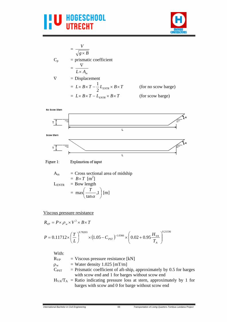
International Bachelor in Civil Engineering 69 Transportation of Living Quarters-Tombua Landana Project
= Bg
V×
Cp = prismatic coefficient
= mAL×
∇
∇ = Displacement
= TBLTBL ENTR ××−××21 (for no scow barge)
= TBLTBL ENTR ××−×× (for scow barge)
Am = Cross sectional area of midship = TB× [m2] LENTR = Bow length
= ⎟⎠⎞
⎜⎝⎛ 1,
tanmax
αT [m]
Viscous pressure resistance
TBVPR wVP ××××= 2ρ
( )21336.0
0366.178203.0
95.002.005.111712.0 ⎟⎟⎠
⎞⎜⎜⎝
⎛+×−×⎟
⎠⎞
⎜⎝⎛×= −
A
VAPST T
HC
LTP
With: RVP = Viscous pressure resistance [kN] ρw = Water density 1.025 [mT/m] CPST = Prismatic coefficient of aft-ship, approximately by 0.5 for barges
with scow end and 1 for barges without scow end HVA/TA = Ratio indicating pressure loss at stern, approximately by 1 for
barges with scow and 0 for barge without scow end
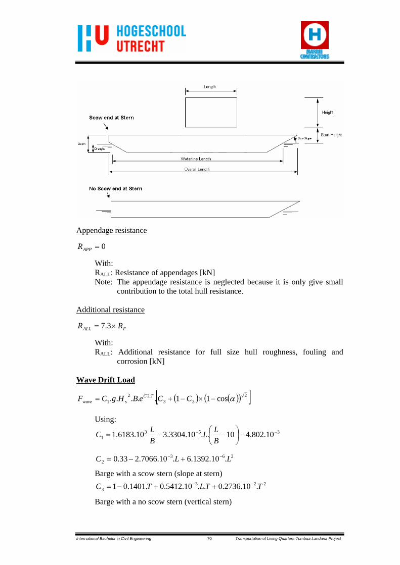
International Bachelor in Civil Engineering 70 Transportation of Living Quarters-Tombua Landana Project
Appendage resistance
0=APPR
With: RALL: Resistance of appendages [kN] Note: The appendage resistance is neglected because it is only give small
contribution to the total hull resistance.
Additional resistance
FALL RR ×= 3.7
With: RALL: Additional resistance for full size hull roughness, fouling and
corrosion [kN]
Wave Drift Load
( ) ( )( )[ ]233
.221 cos11..... α−×−+= CCeBHgCF TC
swave Using:
3531 10.802.410..10.3304.310.6183.1 −− −⎟
⎠⎞
⎜⎝⎛ −−=
BLL
BLC
2632 .10.1392.6.10.7066.233.0 LLC −− +−=
Barge with a scow stern (slope at stern)
2233 .10.2736.0..10.5412.0.1401.01 TTLTC −− ++−=
Barge with a no scow stern (vertical stern)

International Bachelor in Civil Engineering 71 Transportation of Living Quarters-Tombua Landana Project
2233 .10.3519.0..10.31457.0.1036.01 TTLTC −− ++−=
With: Fwave : Wave drift force [kN] g : Gravitational acceleration [m/s2] Hs : Significant wave height [m] B : Width of barge [m] T : Draft of barge [m] L : Length of barge at waterline [m] α : Slope of bow w.r.t. water surface [deg]

International Bachelor in Civil Engineering 72 Transportation of Living Quarters-Tombua Landana Project
LIST OF APPENDIXES
Appendix A Heerema Marine Contractors (HMC) Report
Appendix B Transportation Forces Calculation
Appendix C Load-out Phases
Appendix D Invader Tug
Appendix E Emergency Towing Gear
Appendix F Installation Phases


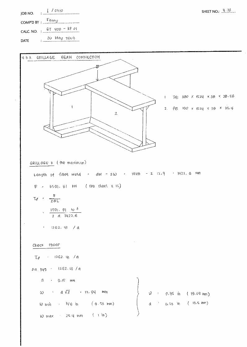


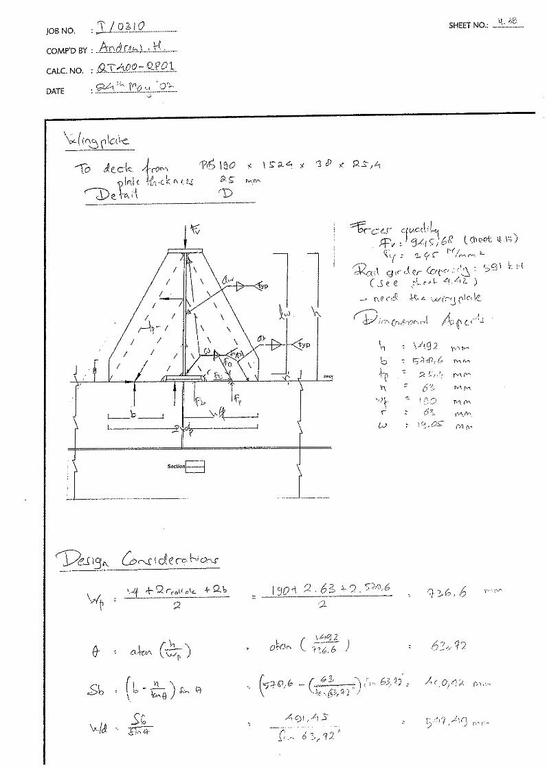


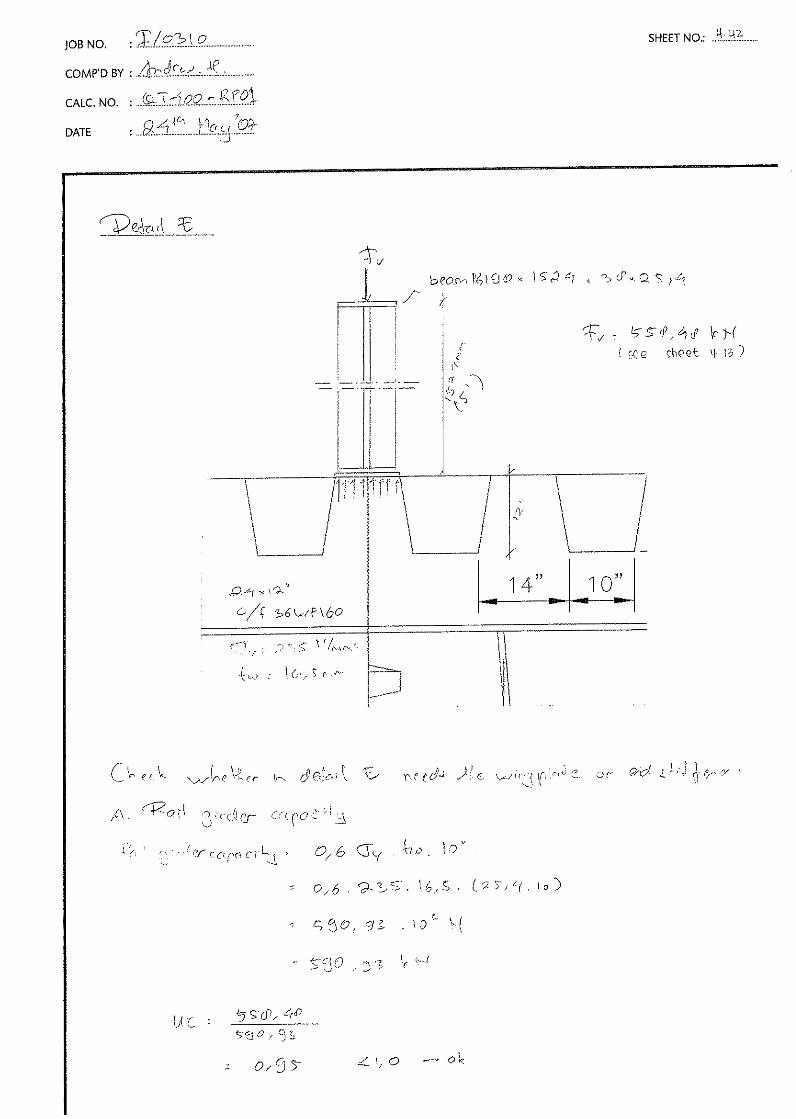


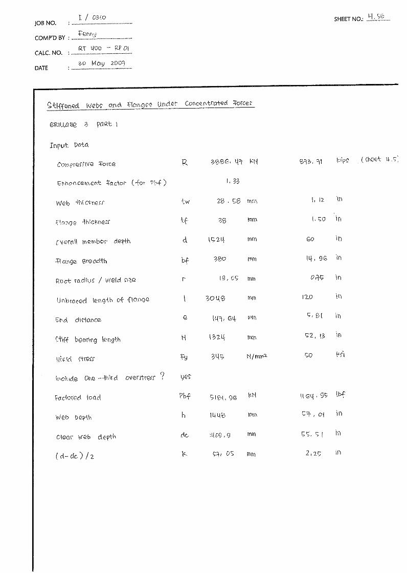


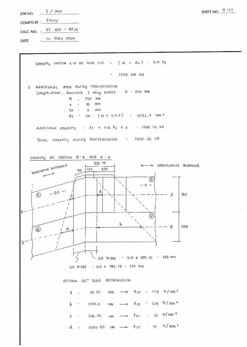


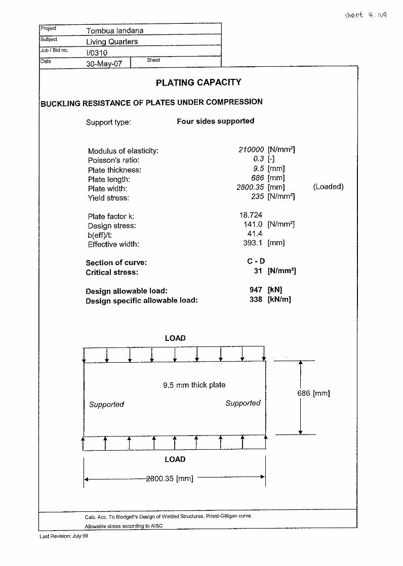
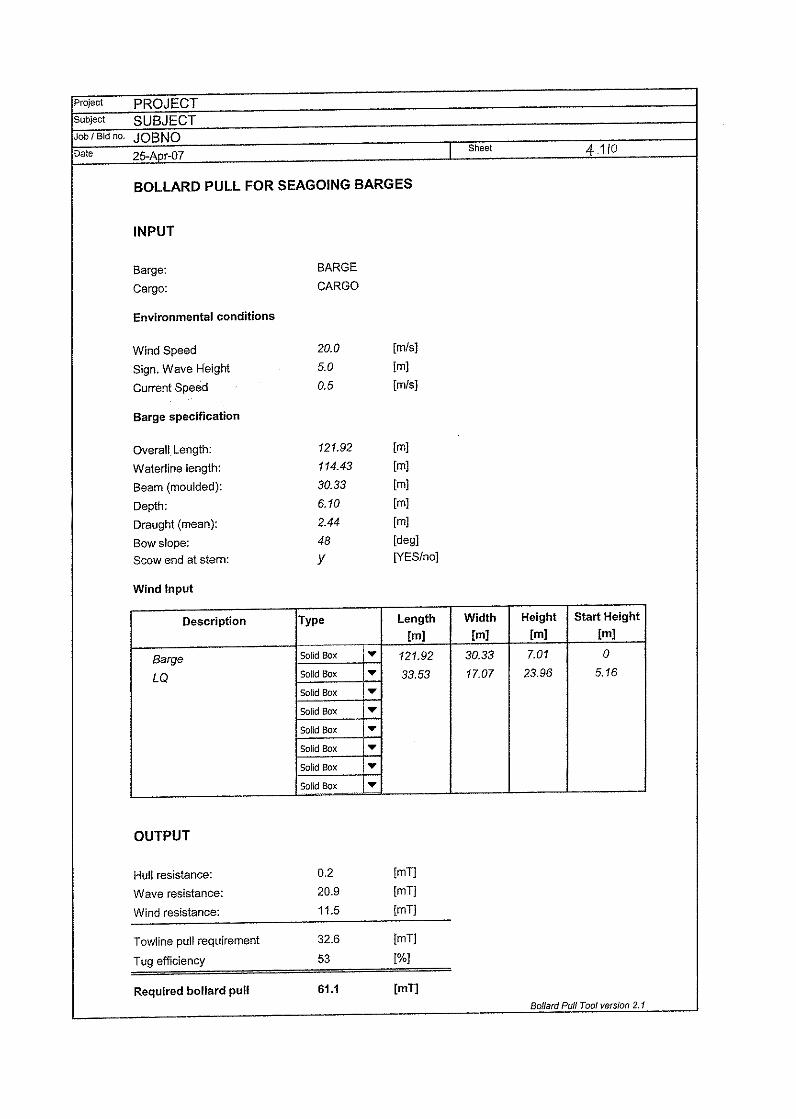


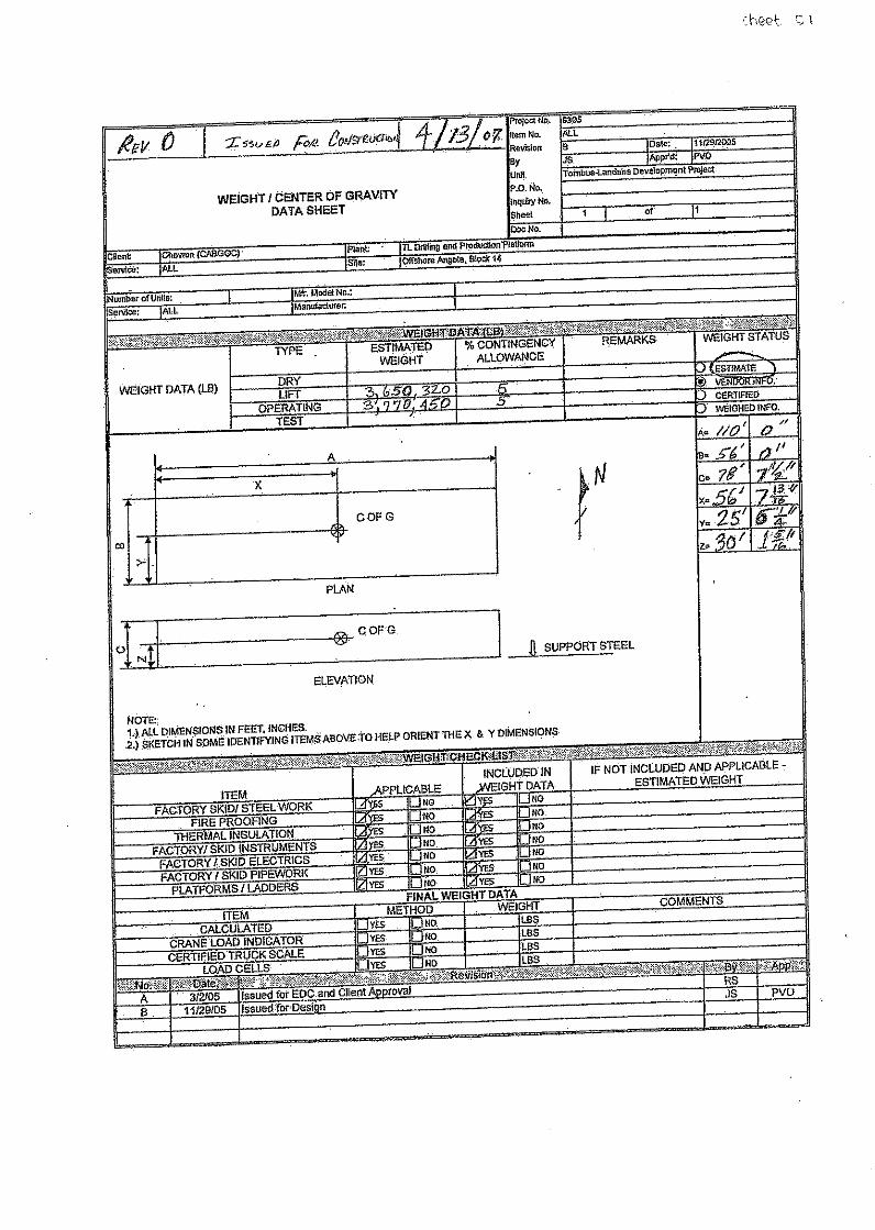


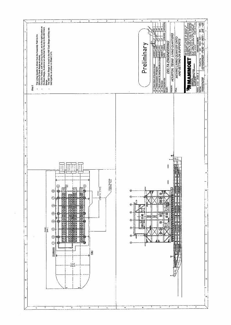


Related Documents