Load: 18-1467 Installation Manual for your Miracle PlaySystem Please see (Online): READ ME FIRST • CPSC Handbook • Install 101 and Hardware Guide • Inside Construction Drawings and Footing Layouts • Installation Guides • Parts List of every component in your Playsystem • YOLO, COUNTY OF WOODLAND, CA Work Order: MR00112258

Welcome message from author
This document is posted to help you gain knowledge. Please leave a comment to let me know what you think about it! Share it to your friends and learn new things together.
Transcript

Load: 18-1467
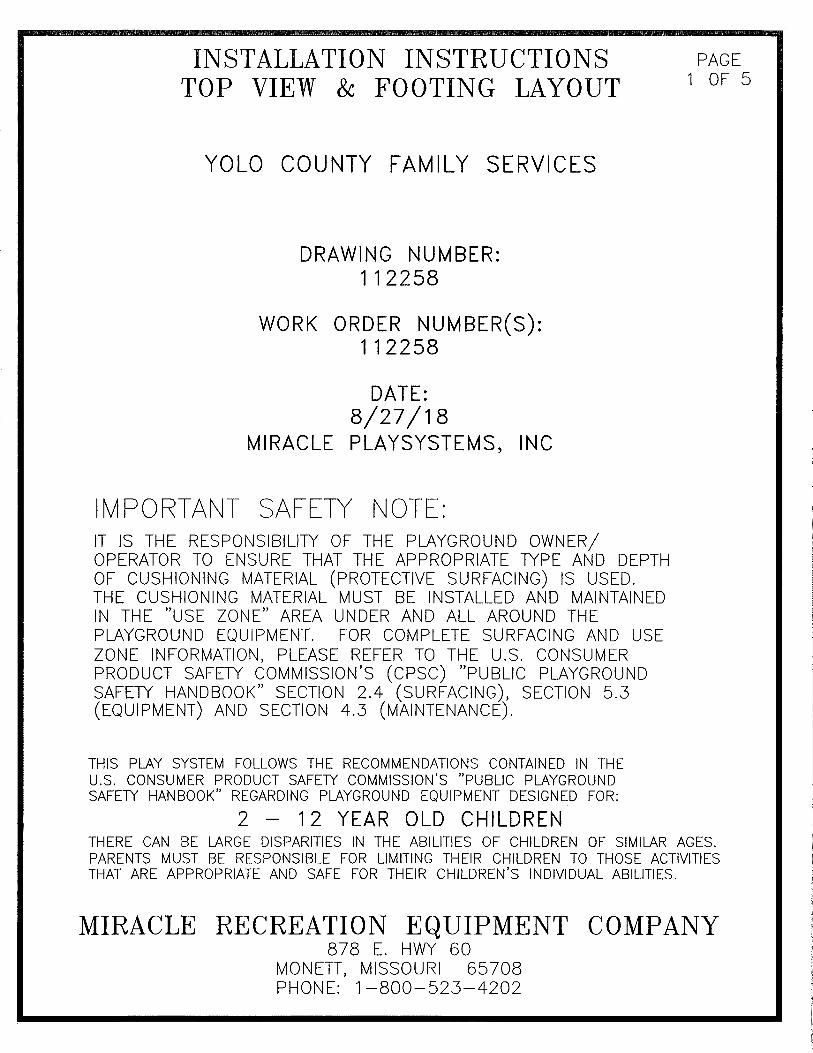
Installation Manualfor your Miracle PlaySystem
Please see (Online):READ ME FIRST•CPSC Handbook•Install 101 and Hardware Guide•
InsideConstruction Drawings and Footing Layouts•Installation Guides•Parts List of every component in your
Playsystem
•
YOLO, COUNTY OFWOODLAND, CA
Work Order: MR00112258
�������������� ����������������� �����������������������
���
����
��
����
��
��
����������
���� �� �� ��������
�������
������������
���������������������������������� �� �����
���������������
����
����
�����
����
����
�����
����
���
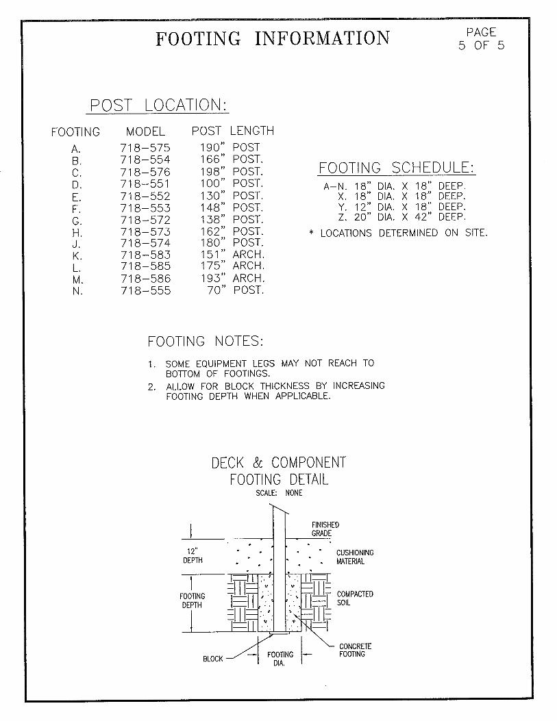
������������� ������������������������������������� ������ �������������������������������������������������������������������� ������������������������������������������������ ������������ ��������������������������������������������
�� ��������������������������������������� �������� ������������������������������������������!"����!������� �������#����$���$��������������������� �����#������#��� ���������������!$��������!������� �������#������ ����%��������� �����#�������#�����������������������������������������������������&�
�����'�()*�(+* , $����-���)&�����'�()*�(+*�) , $����&���-�����'�()*�(+*�& , $����&���)&
������������
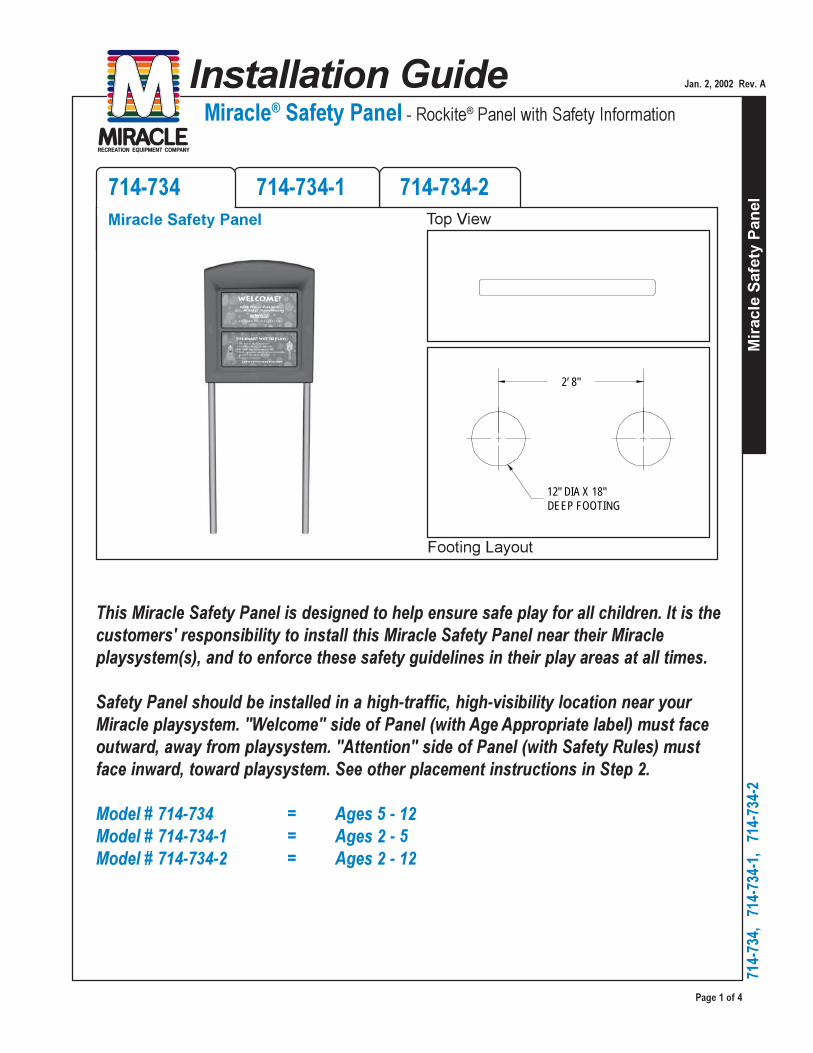
��������������������������������������������������� ������������������ ����
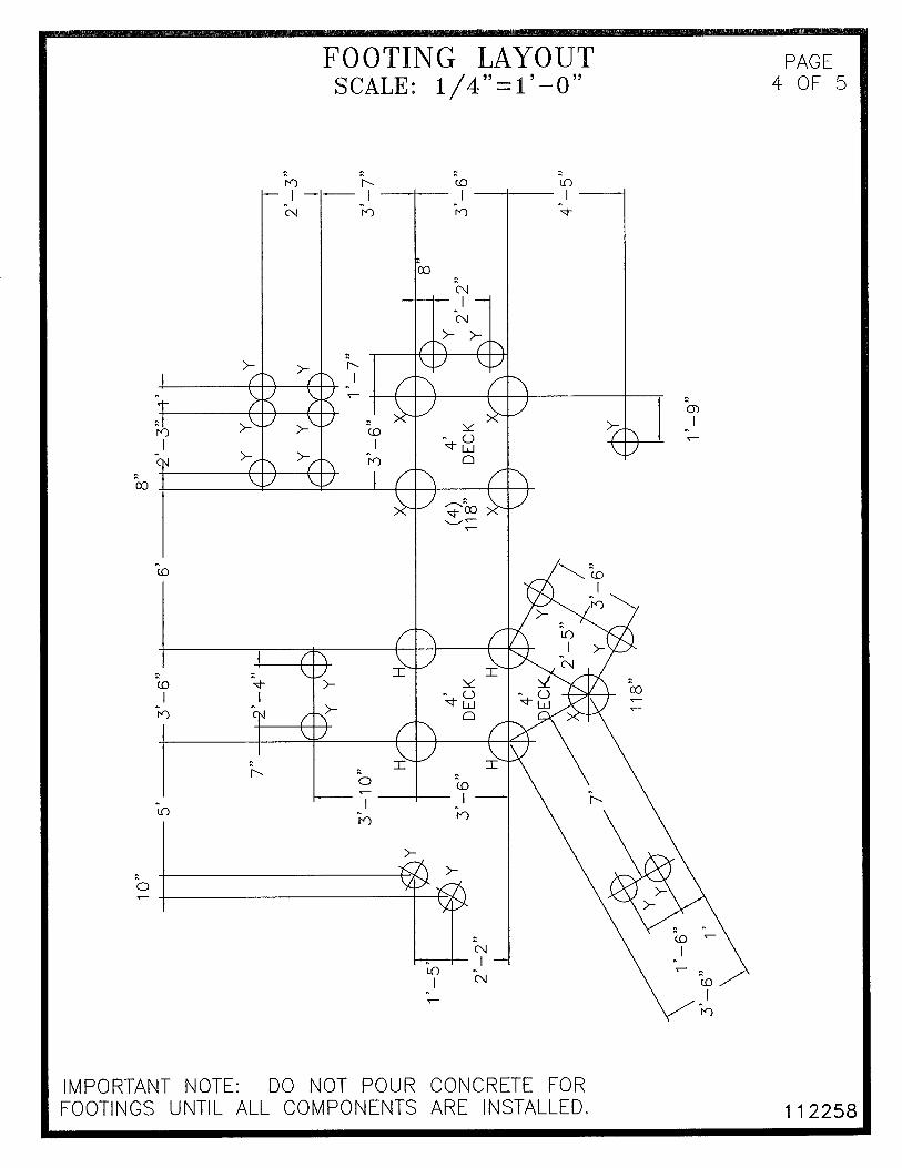
12" DIA X 18"DEEP FOOTING
2’ 8"
������������������
���������
���
����
��
����
��
��
�������������� ����������������� �����������������������
����
����
�����
����
����
�����
����
���
����������������
�� �����������������
����������������������� ����� ������ ��������������� ������ ������ �
���!������������������"��� ������������#�"�$��� ����%���"�������%&& ����'�������(%�&�����������������)�&�*����+ ,�&������ �*����,��%��-���.������������� ��)�# �,����*�&���,�&������ ����,���������,�/��������*�,����- ��0�&����%����*� + $��1#�������������2���*% ������� ������������%�
� ������������������������������������ ������������������������������������� ���!��!������"�"�
�����������
� ������ ���
���
����
��
����
��
��
�������������� ����������������� �����������������������
������������������
���������
����
����
�����
����
����
�����
����
���
������������������ �������������������� ���������� ������������������� �������������������� ��������������������������������������������������!���������" # ������ ���������������"�$
������������� ������������������������������������������������������ ��������� � ��������������������%�������� ������������������������������������
������
������
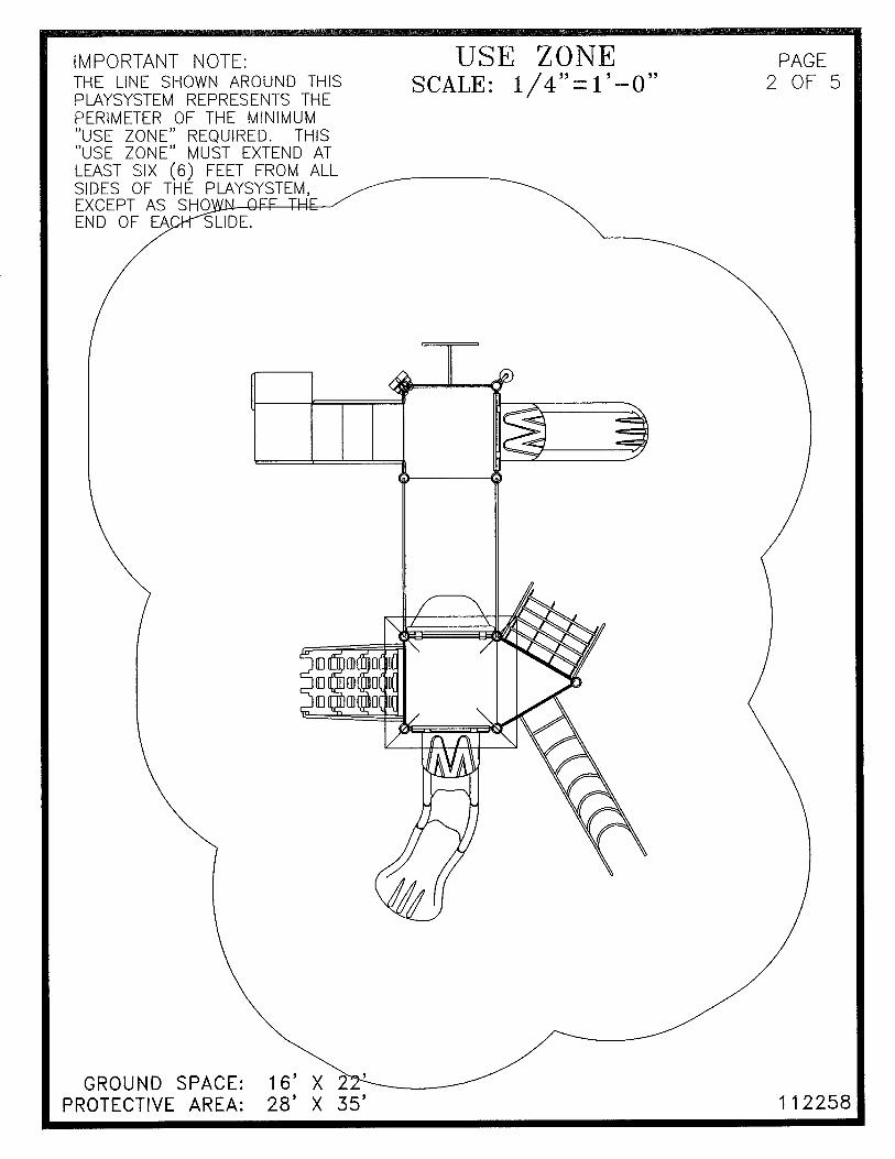
��"�&�����"����������������������� �����������'������������������"� �������� ���!"����#�������������
���$��"�������� � �������� ���!������#���!��%����#���������������##������������ ����������� �������������#�&�#������#���
������
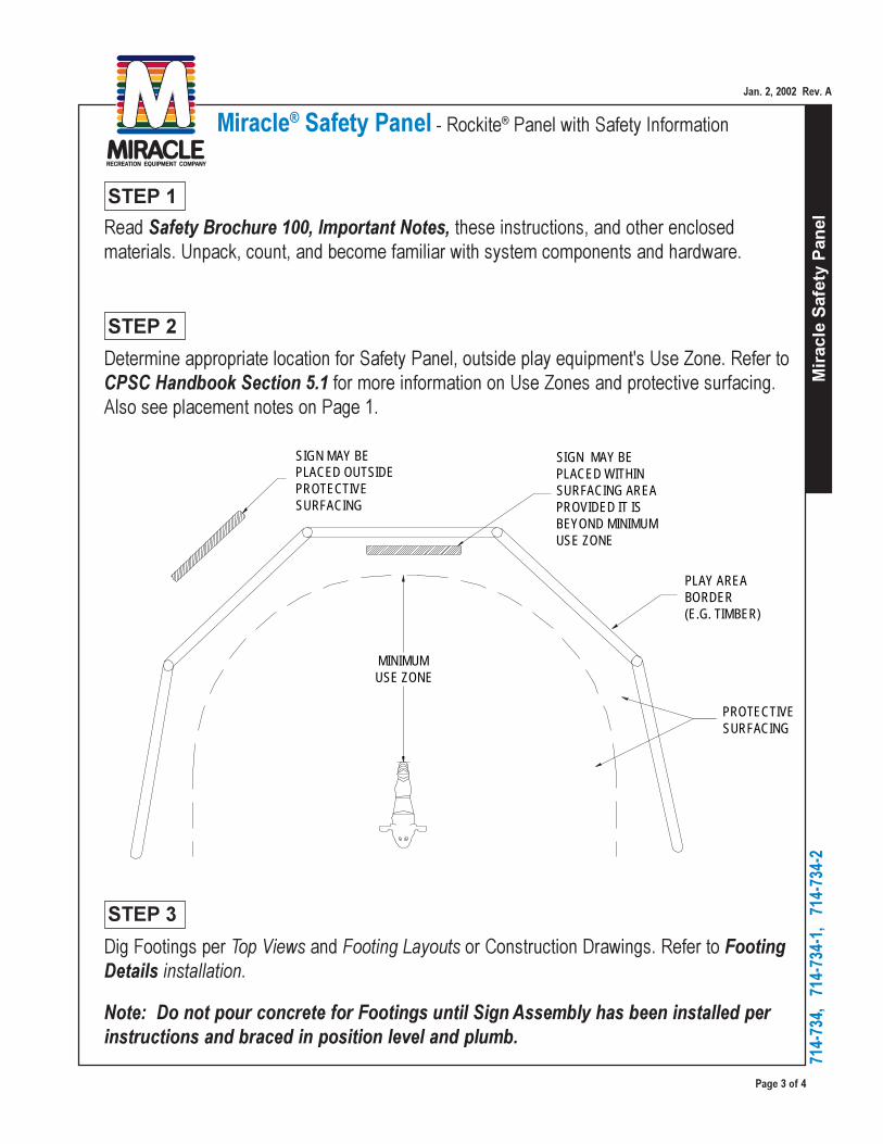
MINIMUM USE ZONE
SIGN MAY BE PLACED OUTSIDEPROTECTIVESURFACING
SIGN MAY BEPLACED WITHINSURFACING AREAPROVIDED IT IS BEYOND MINIMUM USE ZONE
PLAY AREABORDER(E.G. TIMBER)
PROTECTIVESURFACING

������������������
���������
���
����
��
����
��
��
�������������� ����������������� �����������������������
����
����
�����
����
����
�����
����
���
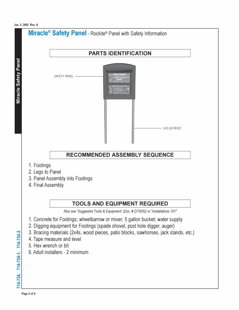
PANEL
LEG
3/8" X 2 BH LAG SCREW
5/16" LOCK WASHER
(2TYP)
(2TYP)
��������
����
��������������������������� ����� ��� ��������� ����������� ������� ������� ��������� ����������������������������������������
VARIES
3’
18"
12"DIA
COMPACTEDSOIL
PROTECTIVESURFACING(OPTIONAL)
ATTENTION
CONCRETEFOOTING
����
����������������������� ������������ ������ ��������!������������ ������������������� ���������� ����������������"�
#���� �������������������� �������������������������������������� �$������������ ����� ���������������� �������� ������������������� ������������������$����������������������������������������������
�� ����� ��������� ���������������������������� ������ �����������
�����������������������������������

Vers
alok
Fas
teni
ng S
yste
m
Page 1 of 6
718-
500
Tots' Choice®
Versalok® Fastening System
January 12, 2018
Rev. PInstallation Guide
718-500Versalok® Fastening System
Models included in this installation guide:
MODEL DESCRIPTION PAGE 718-500 Versalok® Fastening System 1
Posts and additional components not included in this assembly.
IMPORTANT! Prior to installation of any components, refer to Playsystem Installation Guidelines and Tips in the Install 101 section of your manual. This section will provide important tips pertaining to site preparation, footings, system stabilization, and other necessary information vital to the success of your installation.
Note: • Deck, deck post, handrails and panel are not included. • Illustration demonstrates completed assembly with common components.• Versalok clamps mount to posts allowing connection of decks, enclosures and other
components.• Support casting designs and hardware vary by component.
Page 2 of 6
Vers
alok
Fas
teni
ng S
yste
m71
8-50
0
Tots' Choice®
Versalok® Fastening System
January 12, 2018
Rev. P
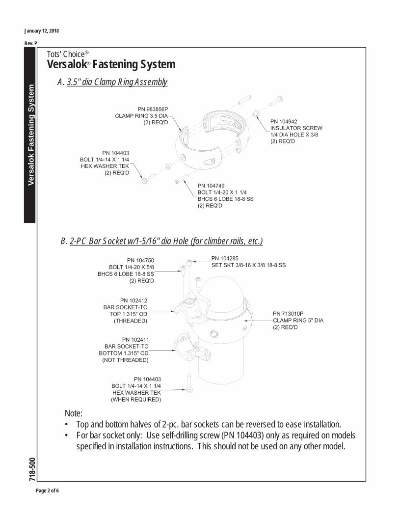
A. 3.5" dia Clamp Ring Assembly
Note: • Top and bottom halves of 2-pc. bar sockets can be reversed to ease installation.• For bar socket only: Use self-drilling screw (PN 104403) only as required on models
specifi ed in installation instructions. This should not be used on any other model.
B. 2-PC Bar Socket w/1-5/16" dia Hole (for climber rails, etc.)
Vers
alok
Fas
teni
ng S
yste
m
Page 3 of 6
718-
500
Tots' Choice®
Versalok® Fastening System
January 12, 2018
Rev. P
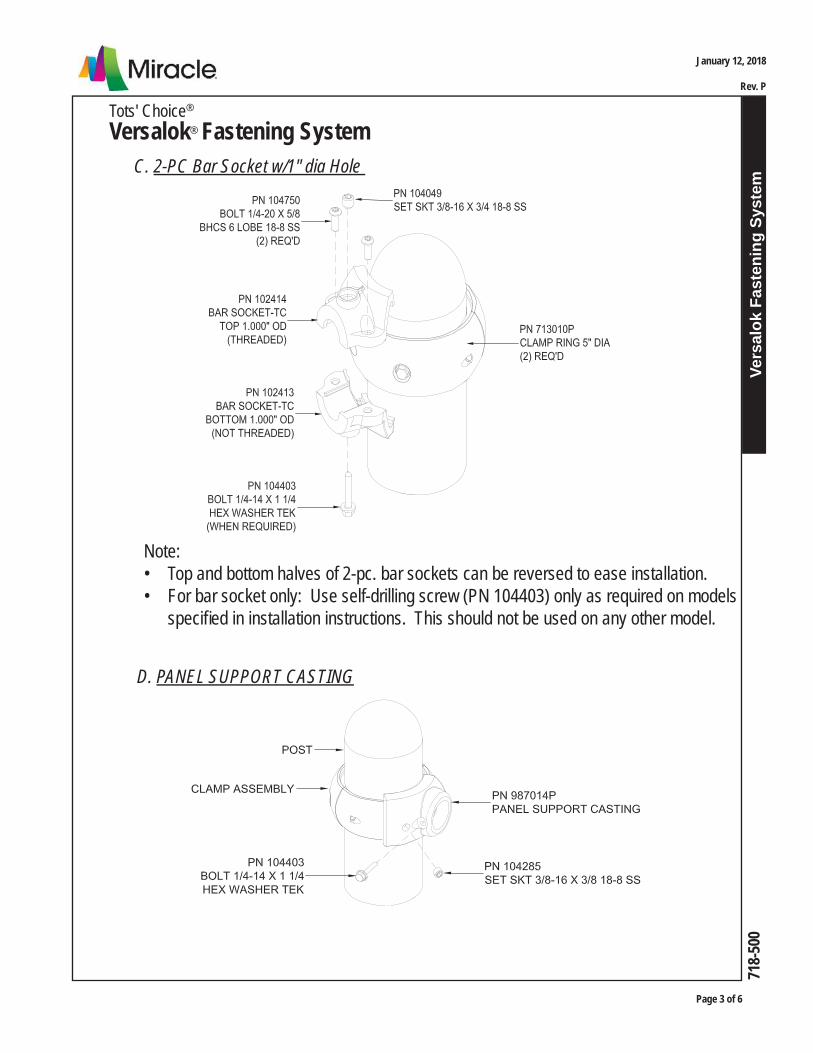
C. 2-PC Bar Socket w/1" dia Hole
Note: • Top and bottom halves of 2-pc. bar sockets can be reversed to ease installation.• For bar socket only: Use self-drilling screw (PN 104403) only as required on models
specifi ed in installation instructions. This should not be used on any other model.
D. PANEL SUPPORT CASTING

Page 4 of 6
Vers
alok
Fas
teni
ng S
yste
m71
8-50
0
Tots' Choice®
Versalok® Fastening System
January 12, 2018
Rev. P
E. Deck Support Casting
F. TCX Header Support Casting
Note: • Refer to specifi c component installation instruction.
Vers
alok
Fas
teni
ng S
yste
m
Page 5 of 6
718-
500
Tots' Choice®
Versalok® Fastening System
January 12, 2018
Rev. P
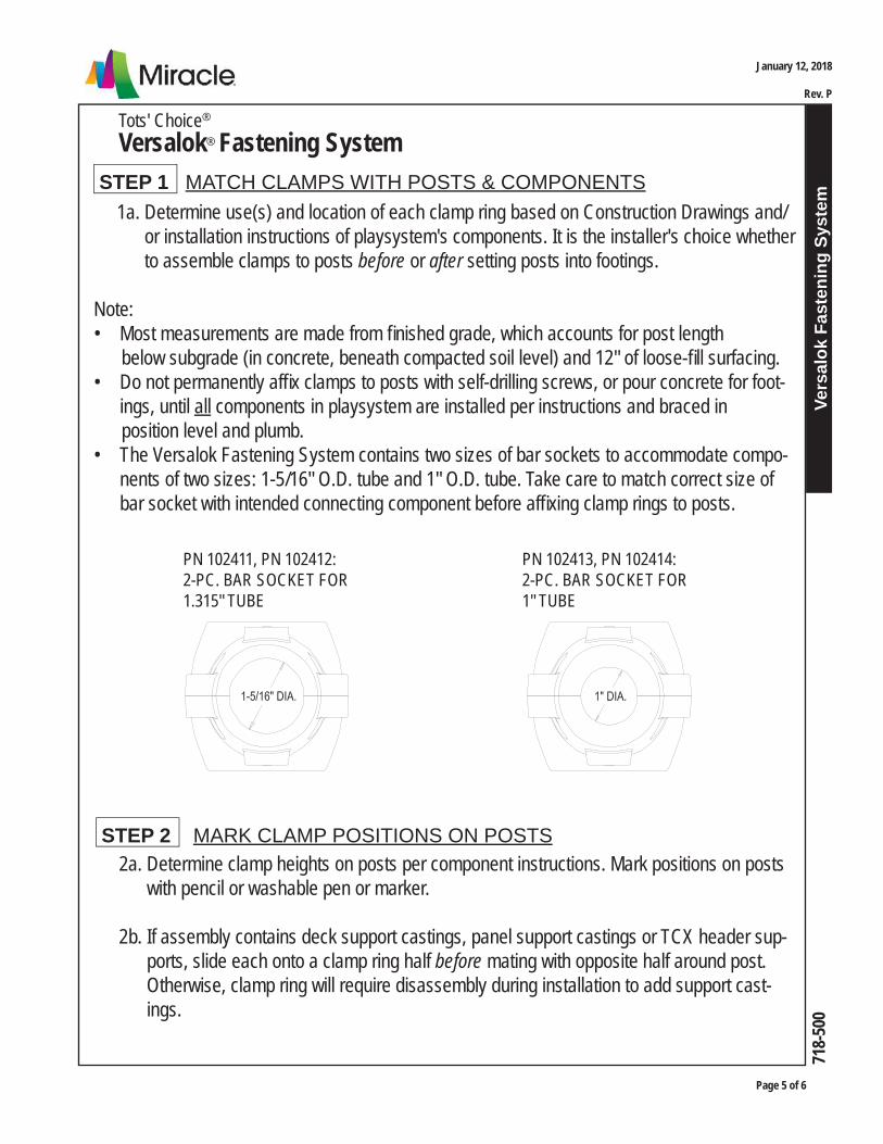
STEP 1 MATCH CLAMPS WITH POSTS & COMPONENTS 1a. Determine use(s) and location of each clamp ring based on Construction Drawings and/ or installation instructions of playsystem's components. It is the installer's choice whether to assemble clamps to posts before or after setting posts into footings.
Note: • Most measurements are made from fi nished grade, which accounts for post length below subgrade (in concrete, beneath compacted soil level) and 12" of loose-fi ll surfacing.• Do not permanently affi x clamps to posts with self-drilling screws, or pour concrete for foot-
ings, until all components in playsystem are installed per instructions and braced in position level and plumb.• The Versalok Fastening System contains two sizes of bar sockets to accommodate compo-
nents of two sizes: 1-5/16" O.D. tube and 1" O.D. tube. Take care to match correct size of bar socket with intended connecting component before affi xing clamp rings to posts.
PN 102411, PN 102412: 2-PC. BAR SOCKET FOR 1.315" TUBE
PN 102413, PN 102414: 2-PC. BAR SOCKET FOR 1" TUBE
STEP 2 MARK CLAMP POSITIONS ON POSTS 2a. Determine clamp heights on posts per component instructions. Mark positions on posts with pencil or washable pen or marker.
2b. If assembly contains deck support castings, panel support castings or TCX header sup- ports, slide each onto a clamp ring half before mating with opposite half around post. Otherwise, clamp ring will require disassembly during installation to add support cast- ings.
Page 6 of 6
Vers
alok
Fas
teni
ng S
yste
m71
8-50
0
Tots' Choice®
Versalok® Fastening System
January 12, 2018
Rev. P
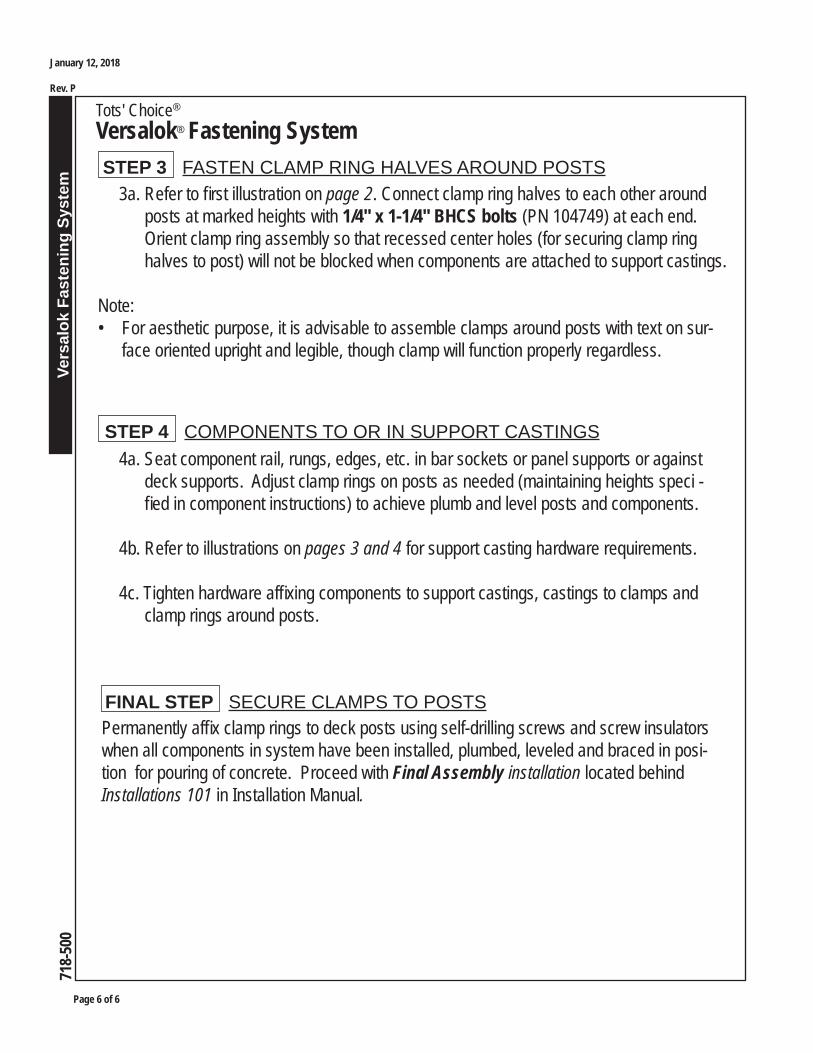
STEP 3 FASTEN CLAMP RING HALVES AROUND POSTS 3a. Refer to fi rst illustration on page 2. Connect clamp ring halves to each other around posts at marked heights with 1/4" x 1-1/4" BHCS bolts (PN 104749) at each end. Orient clamp ring assembly so that recessed center holes (for securing clamp ring halves to post) will not be blocked when components are attached to support castings.
Note: • For aesthetic purpose, it is advisable to assemble clamps around posts with text on sur-
face oriented upright and legible, though clamp will function properly regardless.
STEP 4 COMPONENTS TO OR IN SUPPORT CASTINGS 4a. Seat component rail, rungs, edges, etc. in bar sockets or panel supports or against deck supports. Adjust clamp rings on posts as needed (maintaining heights speci - fi ed in component instructions) to achieve plumb and level posts and components.
4b. Refer to illustrations on pages 3 and 4 for support casting hardware requirements.
4c. Tighten hardware affi xing components to support castings, castings to clamps and clamp rings around posts.
FINAL STEP SECURE CLAMPS TO POSTSPermanently affi x clamp rings to deck posts using self-drilling screws and screw insulators when all components in system have been installed, plumbed, leveled and braced in posi-tion for pouring of concrete. Proceed with Final Assembly installation located behind Installations 101 in Installation Manual.
Deck Posts & Components
Tots' ChoiceTM
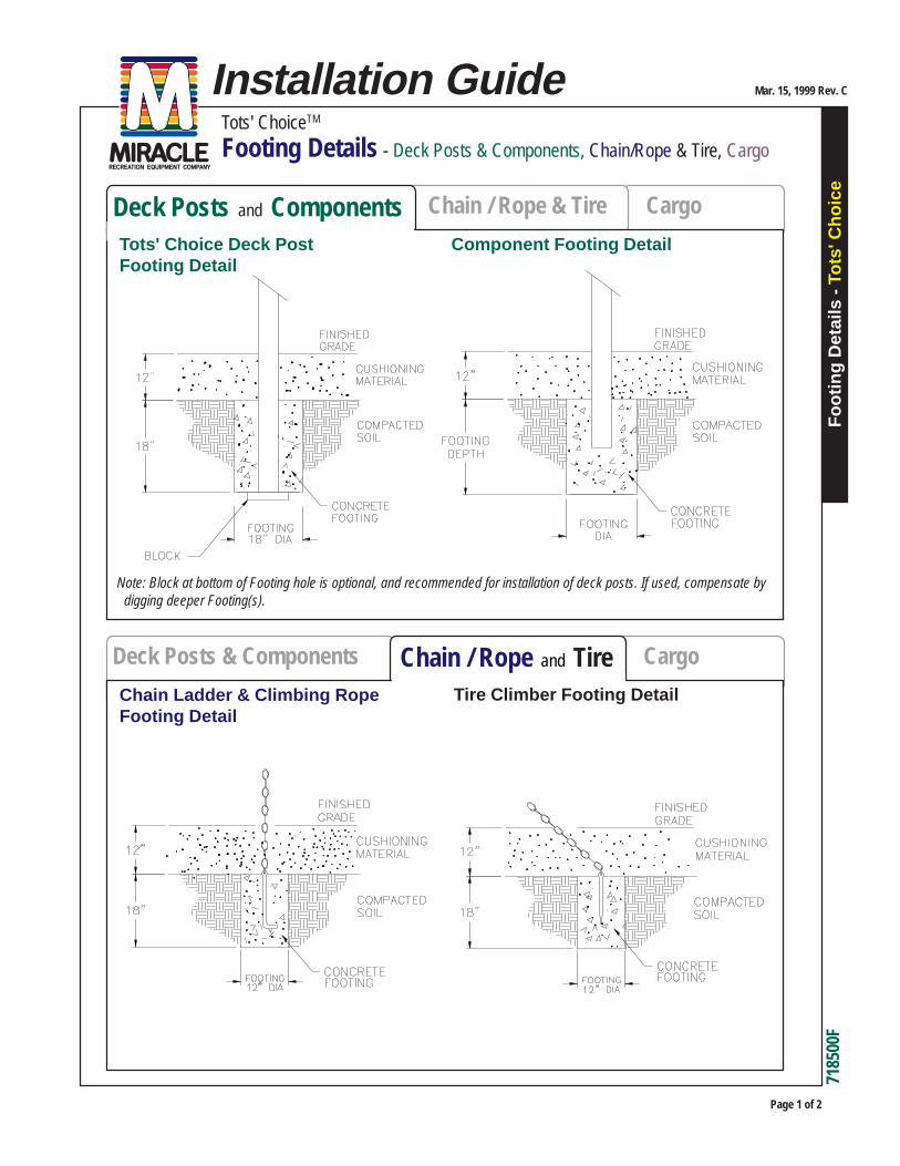
Footing Details - Deck Posts & Components, Chain/Rope & Tire, Cargo
Foo
ting
Det
ails
-
Tots
' Cho
ice
Page 1 of 2
Mar. 15, 1999 Rev. CInstallation Guide
7185
00F
Chain / Rope & Tire CargoDeck Posts and Components
Cargo
Chain Ladder & Climbing RopeFooting Detail
Chain / Rope and TireTire Climber Footing Detail
Component Footing DetailTots' Choice Deck PostFooting Detail
Note: Block at bottom of Footing hole is optional, and recommended for installation of deck posts. If used, compensate by digging deeper Footing(s).

Foo
ting
Det
ails
-
Tots
' Cho
ice
Tots' ChoiceTM
Footing Details - Deck Posts & Components, Chain/Rope & Tire, Cargo
Mar. 15, 1999 Rev. C
Page 2 of 2
7185
00F
Chain / Rope & TireDeck Posts & Components
Cargo Net & Cargo ClimberFooting Detail
Cargo Net / Climber
Dec
ks
Tots' Choice® - Mira-Therm II
Decks
Page 1 of 6
718-
501-
9,
718-
502-
9,
718-
503-
9,
718-
504-
9
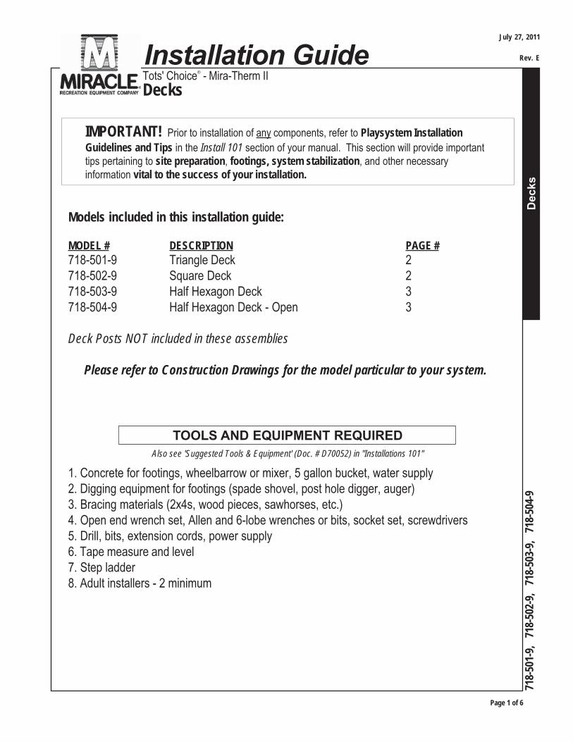
Models included in this installation guide:
MODEL # DESCRIPTION PAGE #
718-501-9 Triangle Deck 2718-502-9 Square Deck 2718-503-9 Half Hexagon Deck 3718-504-9 Half Hexagon Deck - Open 3
Deck Posts NOT included in these assemblies
Please refer to Construction Drawings for the model particular to your system.
IMPORTANT! Prior to installation of any components, refer to Playsystem Installation
Guidelines and Tips in the Install 101 section of your manual. This section will provide importanttips pertaining to site preparation, footings, system stabilization, and other necessaryinformation vital to the success of your installation.
1. Concrete for footings, wheelbarrow or mixer, 5 gallon bucket, water supply2. Digging equipment for footings (spade shovel, post hole digger, auger)3. Bracing materials (2x4s, wood pieces, sawhorses, etc.)4. Open end wrench set, Allen and 6-lobe wrenches or bits, socket set, screwdrivers5. Drill, bits, extension cords, power supply6. Tape measure and level7. Step ladder8. Adult installers - 2 minimum
TOOLS AND EQUIPMENT REQUIREDAlso see 'Suggested Tools & Equipment' (Doc. # D70052) in "Installations 101"
Installation GuideJuly 27, 2011
Rev. E

Page 2 of 6
Dec
ks
Tots' Choice® - Mira-Therm II
Decks
718-
501-
9,
718-
502-
9,
718-
503-
9,
718-
504-
9
Tots' Choice® - Mira-Therm II
Decks
718-501-9Top ViewTriangle Deck (Tri-Deck)
Footing Layout
Model # 718-501-9 requires three (3) Posts.
718-502-9Top View
Square Deck
Footing Layout
Model # 718-502-9 requires four (4) Posts.
3'-6"
1'-9"
3'-6"(3) REQ'D
DEEP FOOTING18" DIA X 18"
3'-6"
3'-6"
18" DIA X 18"DEEP FOOTING
(4) REQ'D
July 27, 2011
Rev. E
Dec
ks
Tots' Choice® - Mira-Therm II
Decks
Page 3 of 6
718-
501-
9,
718-
502-
9,
718-
503-
9,
718-
504-
9
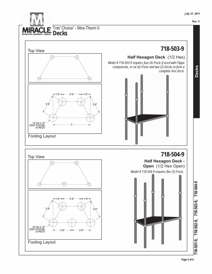
718-503-9Top ViewHalf Hexagon Deck (1/2 Hex)
Footing Layout
718-504-9Half Hexagon Deck -
Open (1/2 Hex Open)
Footing Layout
Model # 718-504-9 requires five (5) Posts.
Top View
1'-9" 3'-6" 1'-9"
7'
3'-6" 3'-6"
18" DIA X 18"DEEP FOOTING
(4) REQ'D
3'-6"
1'-9" 3'-6" 1'-9"
3'-6"
3'-6" 3'-6"(5) REQ'DDEEP FOOTING
18" DIA X 18"
Model # 718-503-9 requires four (4) Posts if used with Flippo components, or six (6) Posts and two (2) Decks to form a
complete Hex Deck.
July 27, 2011
Rev. E
Page 4 of 6
Dec
ks
Tots' Choice® - Mira-Therm II
Decks
718-
501-
9,
718-
502-
9,
718-
503-
9,
718-
504-
9
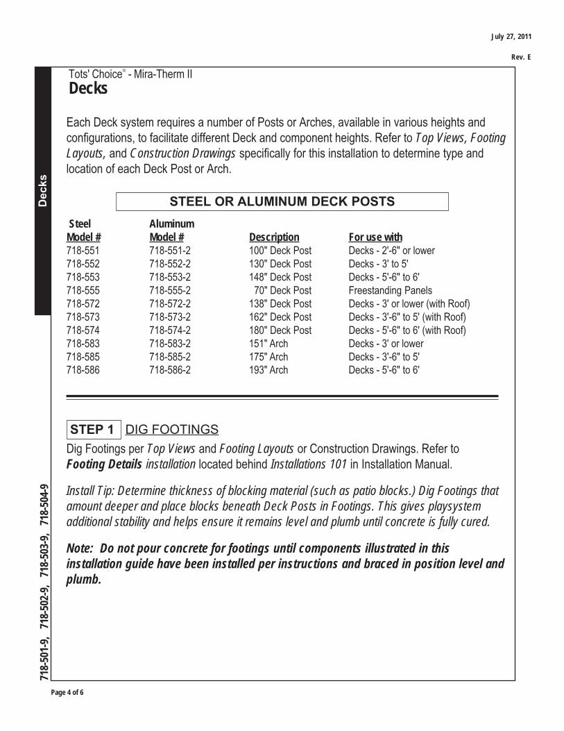
Dig Footings per Top Views and Footing Layouts or Construction Drawings. Refer toFooting Details installation located behind Installations 101 in Installation Manual.
Install Tip: Determine thickness of blocking material (such as patio blocks.) Dig Footings thatamount deeper and place blocks beneath Deck Posts in Footings. This gives playsystemadditional stability and helps ensure it remains level and plumb until concrete is fully cured.
Note: Do not pour concrete for footings until components illustrated in thisinstallation guide have been installed per instructions and braced in position level andplumb.
STEP 1 DIG FOOTINGS
STEEL OR ALUMINUM DECK POSTS Steel AluminumModel # Model # Description For use with718-551 718-551-2 100" Deck Post Decks - 2'-6" or lower718-552 718-552-2 130" Deck Post Decks - 3' to 5'718-553 718-553-2 148" Deck Post Decks - 5'-6" to 6'718-555 718-555-2 70" Deck Post Freestanding Panels718-572 718-572-2 138" Deck Post Decks - 3' or lower (with Roof)718-573 718-573-2 162" Deck Post Decks - 3'-6" to 5' (with Roof)718-574 718-574-2 180" Deck Post Decks - 5'-6" to 6' (with Roof)718-583 718-583-2 151" Arch Decks - 3' or lower718-585 718-585-2 175" Arch Decks - 3'-6" to 5'718-586 718-586-2 193" Arch Decks - 5'-6" to 6'
Each Deck system requires a number of Posts or Arches, available in various heights andconfigurations, to facilitate different Deck and component heights. Refer to Top Views, FootingLayouts, and Construction Drawings specifically for this installation to determine type andlocation of each Deck Post or Arch.
July 27, 2011
Rev. E
Dec
ks
Tots' Choice® - Mira-Therm II
Decks
Page 5 of 6
718-
501-
9,
718-
502-
9,
718-
503-
9,
718-
504-
9
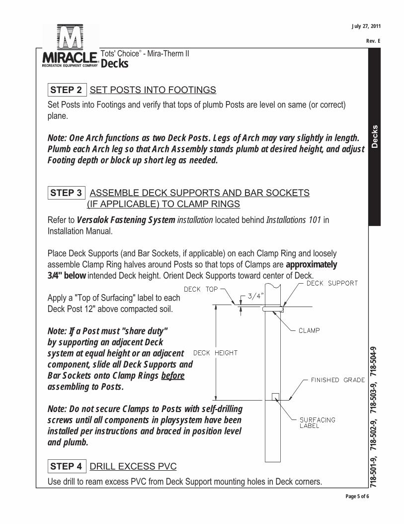
STEP 3 ASSEMBLE DECK SUPPORTS AND BAR SOCKETS (IF APPLICABLE) TO CLAMP RINGS
Use drill to ream excess PVC from Deck Support mounting holes in Deck corners.
STEP 4 DRILL EXCESS PVC
Refer to Versalok Fastening System installation located behind Installations 101 inInstallation Manual.
Place Deck Supports (and Bar Sockets, if applicable) on each Clamp Ring and looselyassemble Clamp Ring halves around Posts so that tops of Clamps are approximately3/4" below intended Deck height. Orient Deck Supports toward center of Deck.
Apply a "Top of Surfacing" label to eachDeck Post 12" above compacted soil.
Note: If a Post must "share duty"by supporting an adjacent Decksystem at equal height or an adjacentcomponent, slide all Deck Supports andBar Sockets onto Clamp Rings beforeassembling to Posts.
Note: Do not secure Clamps to Posts with self-drillingscrews until all components in playsystem have beeninstalled per instructions and braced in position leveland plumb.
Set Posts into Footings and verify that tops of plumb Posts are level on same (or correct)plane.
Note: One Arch functions as two Deck Posts. Legs of Arch may vary slightly in length.Plumb each Arch leg so that Arch Assembly stands plumb at desired height, and adjustFooting depth or block up short leg as needed.
STEP 2 SET POSTS INTO FOOTINGS
July 27, 2011
Rev. E

Page 6 of 6
Dec
ks
Tots' Choice® - Mira-Therm II
Decks
718-
501-
9,
718-
502-
9,
718-
503-
9,
718-
504-
9
Rest Deck on Clamps, and plumb and brace Deck Posts in position. Readjust position ofClamps on Posts as needed to ensure that Deck is level at desired height.
Align Deck corner mounting holes with Deck Supports and attach each with 3/8" x 1-1/4"button head bolt (P/N 104921) and 7/16" I.D. x 1" O.D. flat washer (P/N 117072SS).Do not embed washer in deck coating by overtightening bolt.
Install Tip: Employ a jack stand or other blocking material to support Deck system atproper height until other components are attached, to prevent leaning or twisting of Deckassemblies and to temporarily lend stability.
STEP 5 ATTACH DECK TO POSTS
If installing Deck systems with sections sharing a long side at same height (without a middlePost,) use drill to ream excess deck coating from four (4) mating holes in long side edgeangle on both Deck sections. Secure Deck sections together with 3/8" x 1-1/8" buttonhead bolts (P/N 104930), 3/8" flat washers (P/N 117005) on each side, and 3/8" Nyloknut(P/N 110030).
Deck sections which share a 3'-6" side at same or varying heights attach to common Postsper previous instructions. Deck-to-Deck fastening on a common 3'-6" side is not necessary.
STEP 6 AFFIX DECK SECTIONS TOGETHER; IF APPLICABLE
Square, plumb and level Deck Assembly. Tighten Clamps on Posts, and assemble remainingcomponents to Deck system. When complete, proceed with Final Assembly installationlocated behind Installations 101 in Installation Manual.
FINAL STEP
July 27, 2011
Rev. E
Tots' Choice®
Pre-Installation Preparation of Clamps to Deck Posts
Pre-
Inst
all P
rep
- Cla
mps
to D
eck
Post
s
Page 1 of 3
Installation Guide
718-
522
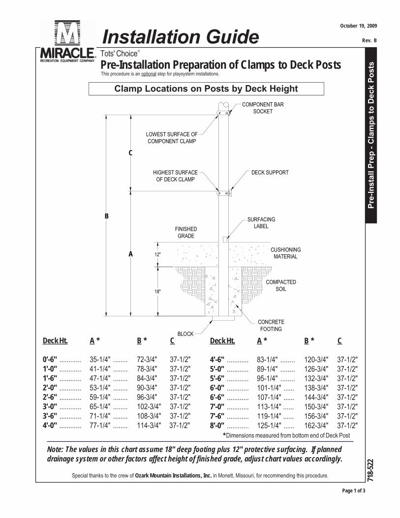
This procedure is an optional step for playsystem installations.
Clamp Locations on Posts by Deck Height
Special thanks to the crew of Ozark Mountain Installations, Inc. in Monett, Missouri, for recommending this procedure.
Note: The values in this chart assume 18" deep footing plus 12" protective surfacing. If planneddrainage system or other factors affect height of finished grade, adjust chart values accordingly.
DECK SUPPORT
COMPONENT BARSOCKET
LOWEST SURFACE OFCOMPONENT CLAMP
HIGHEST SURFACEOF DECK CLAMP
A
B
C
CUSHIONINGMATERIAL
COMPACTED SOIL
CONCRETE FOOTING
BLOCK
FINISHED GRADE
SURFACING LABEL
12"
18"
Deck Ht. A * B * C
0'-6" ............ 35-1/4" ........ 72-3/4" 37-1/2"1'-0" ............ 41-1/4" ........ 78-3/4" 37-1/2"1'-6" ............ 47-1/4" ........ 84-3/4" 37-1/2"2'-0" ............ 53-1/4" ........ 90-3/4" 37-1/2"2'-6" ............ 59-1/4" ........ 96-3/4" 37-1/2"3'-0" ............ 65-1/4" ........ 102-3/4" 37-1/2"3'-6" ............ 71-1/4" ........ 108-3/4" 37-1/2"4'-0" ............ 77-1/4" ........ 114-3/4" 37-1/2"
Deck Ht. A * B * C
4'-6" ............ 83-1/4" ........ 120-3/4" 37-1/2"5'-0" ............ 89-1/4" ........ 126-3/4" 37-1/2"5'-6" ............ 95-1/4" ........ 132-3/4" 37-1/2"6'-0" ............ 101-1/4" ...... 138-3/4" 37-1/2"6'-6" ............ 107-1/4" ...... 144-3/4" 37-1/2"7'-0" ............ 113-1/4" ...... 150-3/4" 37-1/2"7'-6" ............ 119-1/4" ...... 156-3/4" 37-1/2"8'-0" ............ 125-1/4" ...... 162-3/4" 37-1/2" * Dimensions measured from bottom end of Deck Post
October 19, 2009
Rev. B
Page 2 of 3
Pre-
Inst
all P
rep
- Cla
mps
to D
eck
Post
s
Tots' Choice®
Pre-Installation Preparation of Clamps to Deck Posts
718-
522
Many installers prefer to assemble Deck-supporting Clamps and corresponding Component-supporting Clamps around Deck Posts at correct heights all at once as part of their "prepwork," in order to save time and effort during installation of other playsystem components.
Miracle's Installation Guides provide dimensions and instructions for mounting each modeland its parts individually and consecutively, regardless of whether this prep work is completed.It is at the installers' discretion whether to reference this procedure.
The instructions, diagram and chart herein refer to locations for marking and connectingClamps around Deck Posts only (i.e. Posts without Decks do not apply.) Refer to VersalokFastening System installation instructions in this Manual for assembly details.
Note: Do not use self-drilling screws to secure Clamps to Posts until all componentsin system have been installed per instructions, and are plumb, level and braced inposition. This will allow Clamps to be shifted as needed during installation ofremaining components.
It is important to note that until Clamps are permanently secured, Deck systems andother components are UNSAFE TO STAND ON!
Note: This procedure is valid only if footing depths are precise and consistent.Continue only if a transit or other device will be used to verify accuracy.
If Blocks will be placed beneath Deck Posts at bottom of footing holes as recommended,compensate for extra height by digging holes deeper. Refer to Footing Details.
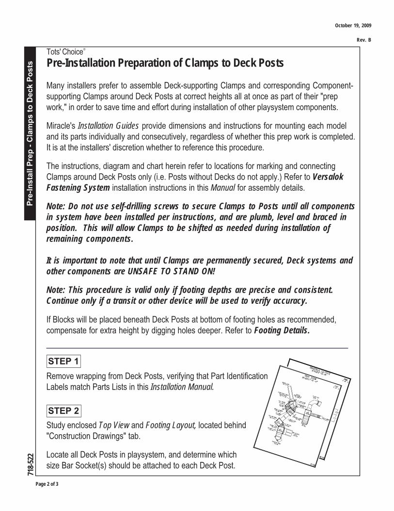
Remove wrapping from Deck Posts, verifying that Part IdentificationLabels match Parts Lists in this Installation Manual.
STEP 1
Study enclosed Top View and Footing Layout, located behind"Construction Drawings" tab.
Locate all Deck Posts in playsystem, and determine whichsize Bar Socket(s) should be attached to each Deck Post.
STEP 2
October 19, 2009
Rev. B
Pre-
Inst
all P
rep
- Cla
mps
to D
eck
Post
s
Tots' Choice®
Pre-Installation Preparation of Clamps to Deck Posts
Page 3 of 3
718-
522
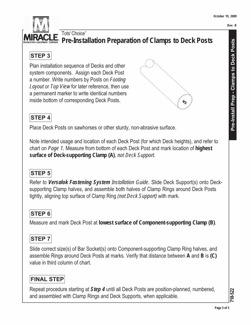
Plan installation sequence of Decks and othersystem components. Assign each Deck Posta number. Write numbers by Posts on FootingLayout or Top View for later reference, then usea permanent marker to write identical numbersinside bottom of corresponding Deck Posts.
STEP 3
Place Deck Posts on sawhorses or other sturdy, non-abrasive surface.
Note intended usage and location of each Deck Post (for which Deck heights), and refer tochart on Page 1. Measure from bottom of each Deck Post and mark location of highestsurface of Deck-supporting Clamp (A), not Deck Support.
STEP 4
STEP 5
STEP 6
Refer to Versalok Fastening System Installation Guide. Slide Deck Support(s) onto Deck-supporting Clamp halves, and assemble both halves of Clamp Rings around Deck Poststightly, aligning top surface of Clamp Ring (not Deck Support) with mark.
Measure and mark Deck Post at lowest surface of Component-supporting Clamp (B).
Repeat procedure starting at Step 4 until all Deck Posts are position-planned, numbered,and assembled with Clamp Rings and Deck Supports, when applicable.
FINAL STEP
Slide correct size(s) of Bar Socket(s) onto Component-supporting Clamp Ring halves, andassemble Rings around Deck Posts at marks. Verify that distance between A and B is (C)value in third column of chart.
STEP 7
5
October 19, 2009
Rev. B
Tots' Choice®
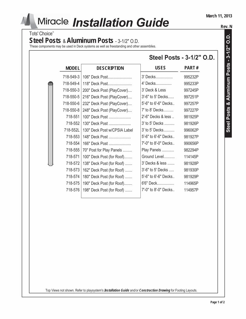
Steel Posts & Aluminum Posts - 3-1/2" O.D.
Stee
l Pos
ts &
Alu
min
um P
osts
- 3-
1/2"
O.D
.
Page 1 of 2
Installation Guide
These components may be used in Deck systems as well as freestanding and other assemblies.
Steel Posts - 3-1/2" O.D.MODEL DESCRIPTION
718-549-3
718-549-4
718-550-3
718-550-5
718-550-6
718-550-8
718-551
718-552
718-552L
718-553
718-554
718-555
718-571
718-572
718-573
718-574
718-575
718-576
PART #
106" Deck Post........................
118" Deck Post........................
200" Deck Post (PlayCover)....
216" Deck Post (PlayCover)....
232" Deck Post (PlayCover)....
248" Deck Post (PlayCover)....
100" Deck Post ......................
130" Deck Post ......................
130" Deck Post w/CPSIA Label
148" Deck Post ......................
166" Deck Post ......................
70" Post for Play Panels .........
100" Deck Post (for Roof)........
138" Deck Post (for Roof) .......
162" Deck Post (for Roof) .......
180" Deck Post (for Roof) .......
190" Deck Post (for Roof)........
198" Deck Post (for Roof) .......
995232P
995233P
997245P
997251P
997257P
997227P
981925P
981926P
996062P
981927P
990656P
982294P
114145P
981928P
981930P
981929P
114965P
114957P
Top Views not shown. Refer to playsystem's Installation Guide and/or Construction Drawing for Footing Layouts.
USES
3' Decks.................
4' Decks................
3' Deck & Less
3'-6" to 5' Decks......
5'-6" to 6'-6" Decks..
7' to 8' Decks..........
2'-6" Decks & less ..
3' to 5' Decks ..........
3' to 5' Decks...........
5'-6" to 6'-6" Decks..
7'-0" to 8'-0" Decks..
Play Panels ............
Ground Level...........
3' Decks & less .......
3'-6" to 5' Decks .....
5'-6" to 6'-6" Decks..
6'6" Deck.................
7'-0" to 8'-0" Decks..
March 11, 2013
Rev. N

Tots' Choice®
Steel Posts & Aluminum Posts- 3-1/2" O.D.
Page 2 of 3
Stee
l Pos
ts &
Alu
min
um P
osts
- 3-
1/2"
O.D
.
718-
549-
3, 7
18-5
49-4
, 71
8-54
9-32
, 71
8-54
9-42
, 71
8-55
0-3,
718
-550
-5,
718-
550-
6, 7
18-5
50-8
, 71
8-55
1,71
8-55
1-2,
718
-552
, 718
-552
L, 7
18-5
52-2
, 718
-552
-2L
, 718
-553
, 718
-553
-2, 7
18-5
54, 7
18-5
55,7
18-5
55-2
,71
8-57
1, 7
18-5
72, 7
18-5
72-2
, 718
-573
, 718
-573
-2, 7
18-5
74, 7
18-5
74-2
, 718
-575
, 718
-576
March 11, 2013
Rev. N
MODEL DESCRIPTION
718-549-32
71-549-42
718-551-2
718-552-2
718-552-2L
718-553-2
718-555-2
718-572-2
718-573-2
718-574-2
PART #
106" Deck Post........................
118" Deck Post.......................
100" Deck Post ......................
130" Deck Post ......................
130" Deck Post w/CPSIA Label
148" Deck Post ......................
70" Post for Play Panels .........
138" Deck Post (for Roof) .......
162" Deck Post (for Roof) .......
180" Deck Post (for Roof) .......
Top Views not shown. Refer to playsystem's Installation Guide and/or Construction Drawing for Footing Layouts.
USES
3' Decks..................
4' Decks.................
2'-6" Decks & less ..
3' to 5' Decks .........
3' to 5' Decks .........
5'-6" to 6'-6" Decks..
Play Panels ............
3' Decks & less .......
3'-6" to 5' Decks .....
5'-6" to 6'-6" Decks..
Aluminum Posts - 3-1/2" O.D.
995234P
995235P
989070P
989071P
996066P
989073P
989069P
989072P
989074P
989075P
Note: Miracle Recreation attaches a CPSIA label to transfer points and 2' stairs. If yourcomposite structure does not have one of these components, there will be ONE post with thelabel attached. This label will be attached so that when installed it will be approximately 6"above finished grade. Ensure this label is readable and not covered by clamps, hardware orother equipment. If you do NOT have a component with label, contact your Miracle salesrepresentative.

Stee
l Pos
ts &
Alu
min
um P
osts
- 3-
1/2"
O.D
.Tots' Choice®
Steel Posts & Aluminum Posts- 3-1/2" O.D.
Page 3 of 3
718-
549-
3, 7
18-5
49-4
, 71
8-54
9-32
, 71
8-54
9-42
, 71
8-55
0-3,
718
-550
-5,
718-
550-
6, 7
18-5
50-8
, 71
8-55
1,71
8-55
1-2,
718
-552
, 718
-552
L, 7
18-5
52-2
, 718
-552
-2L
, 718
-553
, 718
-553
-2, 7
18-5
54, 7
18-5
55,7
18-5
55-2
,71
8-57
1, 7
18-5
72, 7
18-5
72-2
, 718
-573
, 718
-573
-2, 7
18-5
74, 7
18-5
74-2
, 718
-575
, 718
-576
March 11, 2013
Rev. N
Use playsystem's Installation Guide and/or Construction Drawing to determine footinglocations, and use shovel, posthole digger, auger, etc. to dig footings.
Refer to Footing Details installation.
STEP 2 PLACE POSTS INTO FOOTINGSPlace Posts into footings. Plumb and brace in position.
Note: Do not pour concrete for footings, or permanently secure Clamps to Postswith self-drilling screws, until all components in system or freestanding assemblyhave been installed per instructions and braced in position level and plumb.
FINAL STEPInstall remaining Playsystem components per instructions. Verify that components are atcorrect heights, angles, etc., and are plumb and level.
Secure Posts in footings with concrete. Allow 72 hours to cure before removing braces.Refer to Final Assembly installation.
STEP 1 DIG FOOTINGS

4', 5
', 6'
, 6'-6
", 8
' Gro
ove
II Sl
ide
Tots' Choice®
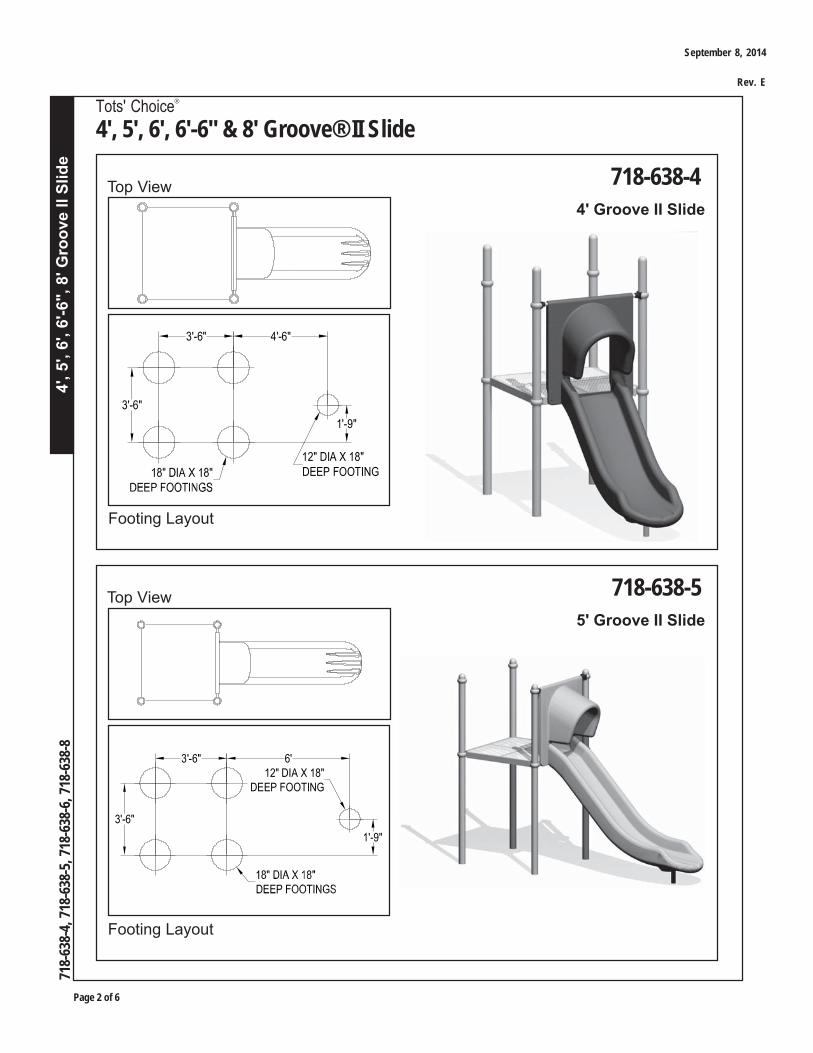
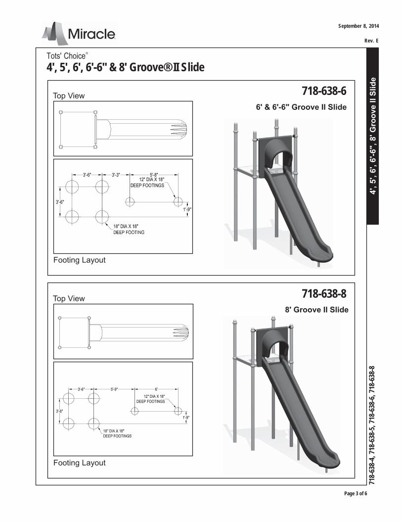
4', 5', 6', 6'-6" & 8' Groove® II Slide
Page 1 of 6
718-
638-
4, 7
18-6
38-5
, 718
-638
-6, 7
18-6
38-8
Installation Guide
1. Concrete for footings, wheelbarrow or mixer, 5 gallon bucket, water supply2. Digging equipment for footing holes (spade shovel, post hole digger, auger)3. Bracing materials (2x4s, wood pieces, concrete blocks, bricks, jack stands, sawhorses, etc.)4. Tape measure and level5. Open end wrench set, Allen and 6-lobe wrenches or bits, socket set, screwdrivers6. Drill, bits, extension cords, power supply7. Step ladder8. Rubber mallet9. Adult installers - 3 minimum
TOOLS & EQUIPMENT REQUIREDAlso see 'Suggested Tools & Equipment' (Doc. # D70052) in "Installations 101"
IMPORTANT! Prior to installation of any components, refer to Playsystem Installation
Guidelines and Tips in the Install 101 section of your manual. This section will provide importanttips pertaining to site preparation, footings, system stabilization, and other necessaryinformation vital to the success of your installation.
NOTE: Deck System not included in this assembly.
Models included in this installation guide:
MODEL # DESCRIPTION PAGE #
718-638-4 Groove II Slide for 4' Deck 2718-638-5 Groove II Slide for 5' Deck 2718-638-6 Groove II Slide for 6' & 6'-6" Deck 3718-638-8 Groove II Slide for 8' Deck 3
Please refer to Construction Drawings for the model particular to your system.
September 8, 2014
Rev. E
Page 2 of 6
4', 5
', 6'
, 6'-6
", 8
' Gro
ove
II Sl
ide
718-
638-
4, 7
18-6
38-5
, 718
-638
-6, 7
18-6
38-8
Tots' Choice®
4', 5', 6', 6'-6" & 8' Groove® II Slide
718-638-5Top View5' Groove II Slide
Footing Layout
718-638-4Top View4' Groove II Slide
Footing Layout
3'-6"
3'-6"
4'-6"
1'-9"
12" DIA X 18"DEEP FOOTING
6'
3'-6"
3'-6"
1'-9"
12" DIA X 18"DEEP FOOTING
September 8, 2014
Rev. E
4', 5
', 6'
, 6'-6
", 8
' Gro
ove
II Sl
ide
Tots' Choice®
4', 5', 6', 6'-6" & 8' Groove® II Slide
Page 3 of 6
718-
638-
4, 7
18-6
38-5
, 718
-638
-6, 7
18-6
38-8
718-638-6Top View6' & 6'-6" Groove II Slide
Footing Layout
718-638-8Top View8' Groove II Slide
Footing Layout
3'-6"
3'-6" 3'-3" 5'-8"
1'-9"
12" DIA X 18"DEEP FOOTINGS
3'-6"
3'-6" 5'-9" 6'
1'-9"
12" DIA X 18"DEEP FOOTINGS
September 8, 2014
Rev. E
Page 4 of 6
4', 5
', 6'
, 6'-6
", 8
' Gro
ove
II Sl
ide
718-
638-
4, 7
18-6
38-5
, 718
-638
-6, 7
18-6
38-8
Tots' Choice®
4', 5', 6', 6'-6" & 8' Groove® II Slide
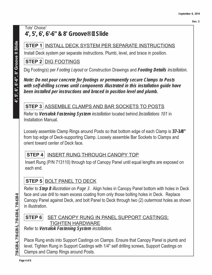
Dig Footing(s) per Footing Layout or Construction Drawings and Footing Details installation.
Note: Do not pour concrete for footings or permanently secure Clamps to Postswith self-drilling screws until components illustrated in this installation guide havebeen installed per instructions and braced in position level and plumb.
STEP 3 ASSEMBLE CLAMPS AND BAR SOCKETS TO POSTS
STEP 2 DIG FOOTINGS
Refer to Versalok Fastening System installation located behind Installations 101 inInstallation Manual.
Loosely assemble Clamp Rings around Posts so that bottom edge of each Clamp is 37-3/8"from top edge of Deck-supporting Clamp. Loosely assemble Bar Sockets to Clamps andorient toward center of Deck face.
Install Deck system per separate instructions. Plumb, level, and brace in position.
STEP 1 INSTALL DECK SYSTEM PER SEPARATE INSTRUCTIONS
Insert Rung (P/N 713110) through top of Canopy Panel until equal lengths are exposed oneach end.
STEP 4 INSERT RUNG THROUGH CANOPY TOP
Refer to Step 8 illustration on Page 3. Align holes in Canopy Panel bottom with holes in Deckface and use drill to ream excess coating from only those bolting holes in Deck. ReplaceCanopy Panel against Deck, and bolt Panel to Deck through two (2) outermost holes as shownin illustration.
STEP 5 BOLT PANEL TO DECK
STEP 6 SET CANOPY RUNG IN PANEL SUPPORT CASTINGS; TIGHTEN HARDWARERefer to Versalok Fastening System installation.
Place Rung ends into Support Castings on Clamps. Ensure that Canopy Panel is plumb andlevel. Tighten Rung in Support Castings with 1/4" self drilling screws, Support Castings onClamps and Clamp Rings around Posts.
September 8, 2014
Rev. E
4', 5
', 6'
, 6'-6
", 8
' Gro
ove
II Sl
ide
Tots' Choice®
4', 5', 6', 6'-6" & 8' Groove® II Slide
Page 5 of 6
718-
638-
4, 7
18-6
38-5
, 718
-638
-6, 7
18-6
38-8
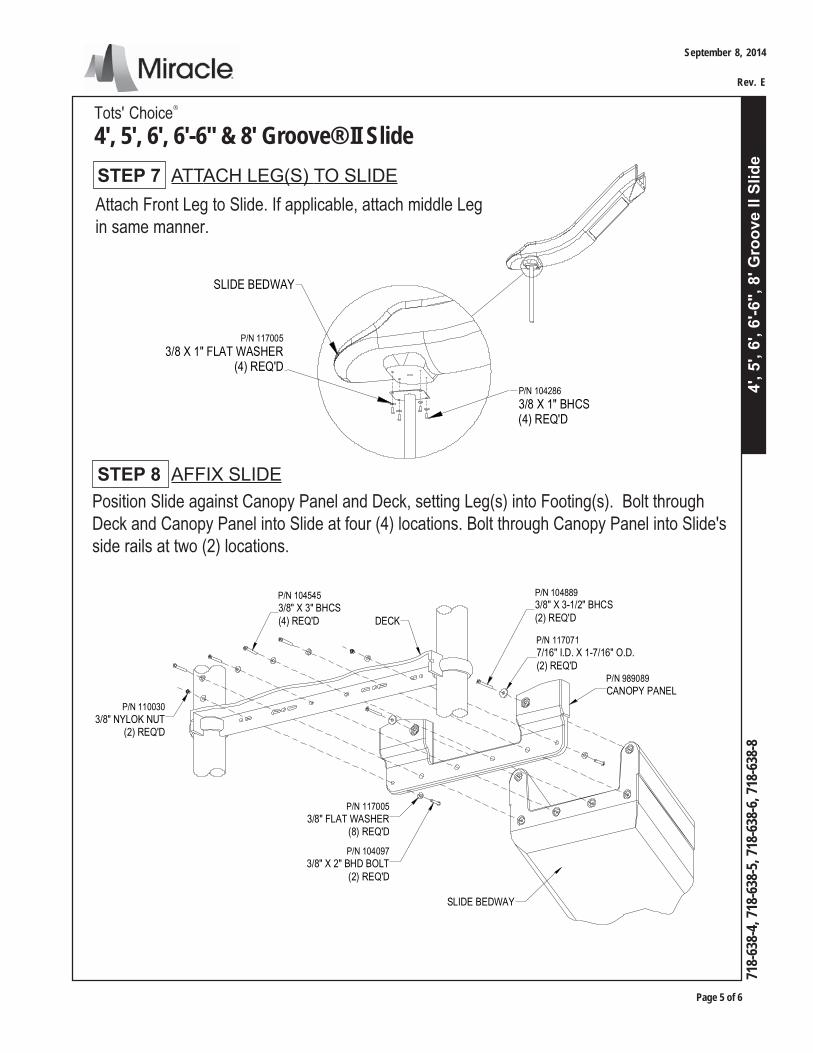
P/N 104286
3/8 X 1" BHCS(4) REQ'D
P/N 117005
3/8 X 1" FLAT WASHER(4) REQ'D
SLIDE BEDWAY
STEP 7 ATTACH LEG(S) TO SLIDEAttach Front Leg to Slide. If applicable, attach middle Legin same manner.
Position Slide against Canopy Panel and Deck, setting Leg(s) into Footing(s). Bolt throughDeck and Canopy Panel into Slide at four (4) locations. Bolt through Canopy Panel into Slide'sside rails at two (2) locations.
STEP 8 AFFIX SLIDE
P/N 117005
3/8" FLAT WASHER(8) REQ'D
P/N 104097
3/8" X 2" BHD BOLT(2) REQ'D
P/N 110030
3/8" NYLOK NUT(2) REQ'D
P/N 104545
3/8" X 3" BHCS(4) REQ'D
P/N 117071
7/16" I.D. X 1-7/16" O.D.(2) REQ'D
P/N 104889
3/8" X 3-1/2" BHCS(2) REQ'DDECK
P/N 989089
CANOPY PANEL
SLIDE BEDWAY
September 8, 2014
Rev. E
Page 6 of 6
4', 5
', 6'
, 6'-6
", 8
' Gro
ove
II Sl
ide
718-
638-
4, 7
18-6
38-5
, 718
-638
-6, 7
18-6
38-8
Tots' Choice®
4', 5', 6', 6'-6" & 8' Groove® II Slide
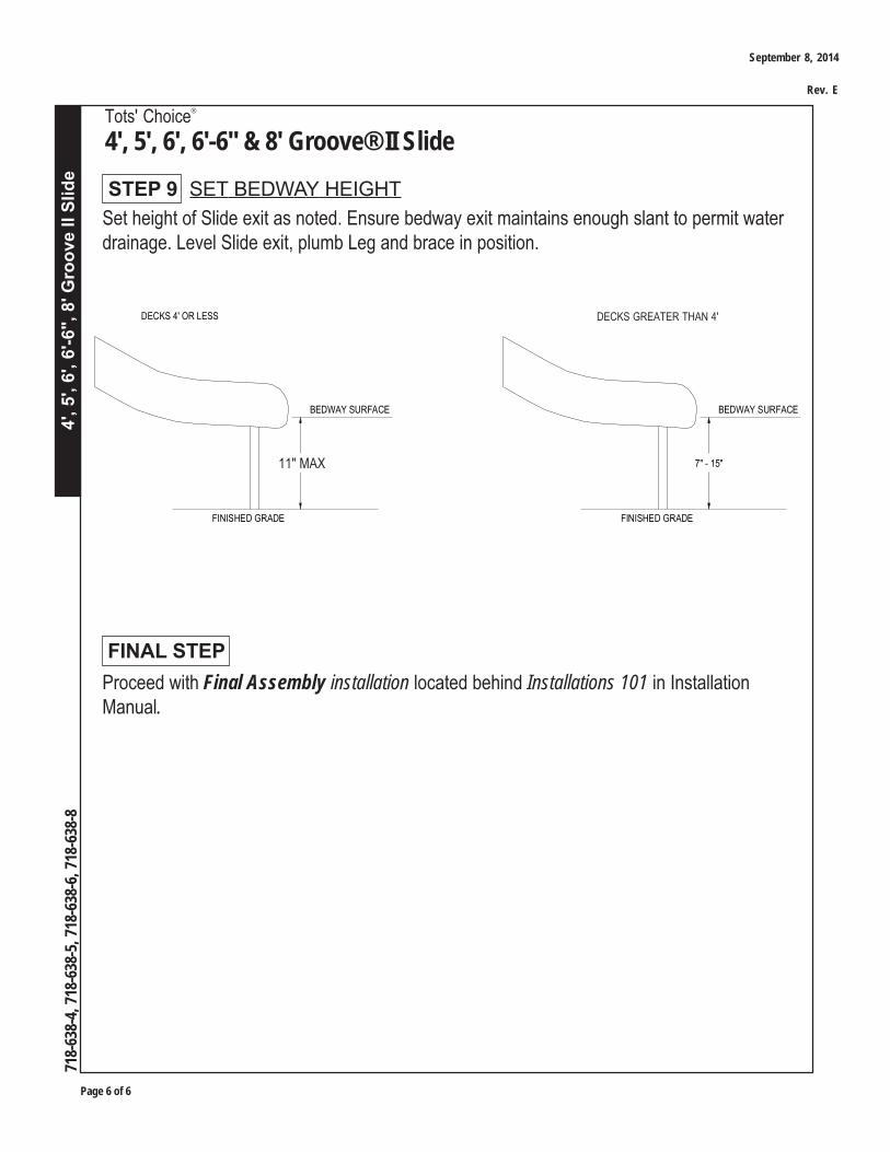
Set height of Slide exit as noted. Ensure bedway exit maintains enough slant to permit waterdrainage. Level Slide exit, plumb Leg and brace in position.
STEP 9 SET BEDWAY HEIGHT
Proceed with Final Assembly installation located behind Installations 101 in InstallationManual.
FINAL STEP
BEDWAY SURFACE
FINISHED GRADE
7" - 11"
DECKS 4' OR LESS
FINISHED GRADE
DECKS 5' OR GREATER
BEDWAY SURFACE
7" - 15"11" MAX
DECKS GREATER THAN 4'
September 8, 2014
Rev. E
Cha
mel
eon
II Sl
ide
Syst
em
Tots' Choice®
Chameleon II Slide System
Page 1 of 10
718-
670,
718-
670-
1, 71
8-76
0-2,
718-
760-
4, 71
8-76
0-5,
718-
760-
6, 71
8-76
0-7
August 01, 2016
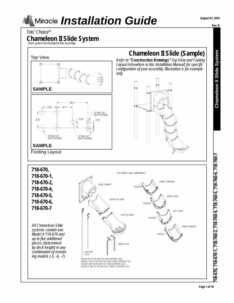
Rev. BInstallation GuideDeck system not included in this assembly.
Footing Layout
Chameleon II Slide (Sample)Top View
718-670, 718-670-1, 718-670-2, 718-670-4, 718-670-5, 718-670-6, 718-670-7
Refer to "Construction Drawings" Top View and Footing Layout (elsewhere in this Installation Manual) for specifi c confi guration of your assembly. Illustration is for example only.
All Chameleon Slide systems contain one Model # 718-670 and up to fi ve additional pieces (determined by deck height) in any combination of remain-ing models (-5, -6, -7).
SAMPLE
SAMPLE
12" DIA X 18"DEEP FOOTING
12" DIA X 18"DEEP FOOTING
18" DIA X 18"DEEP FOOTING
4'-1"8'-2"
1'-8" 1'-5"
2"
3'-6"
3'-6"
SLIDE CANOPY
ENTRY SECTION
EXIT SECTION
FRONT LEGS
SUPPORTLEGS
718-670-4
718-670-5
718-670-6
718-670-7
SHORT STRAIGHT
RIGHT TURN
LEFT TURN
LONG STRAIGHT
718-670; 30" TO 54" DECK HT; NO SUPPORT LEGS718-670-1; 60" TO 78" DECK HT; ONE SHORT SUPPORT LEG718-670-2; 84" TO 96" DECK HT; TWO SUPPORT LEGS718-670-3; 108" TO 120" DECK HT; THREE SUPPORT LEGS
SECTIONAL SLIDE COMPONENTS

Page 2 of 10
Cha
mel
eon
II Sl
ide
Syst
em
Tots' Choice®
Chameleon II Slide System
718-
670,
718-
670-
1, 71
8-76
0-2,
718-
760-
4, 71
8-76
0-5,
718-
760-
6, 71
8-76
0-7
PARTS IDENTIFICATION (SAMPLE)

Cha
mel
eon
II Sl
ide
Syst
em
Tots' Choice®
Chameleon II Slide System
Page 3 of 10
718-
670,
718-
670-
1, 71
8-76
0-2,
718-
760-
4, 71
8-76
0-5,
718-
760-
6, 71
8-76
0-7
August 01, 2016
Rev. B
1. Concrete for footings, wheelbarrow or mixer, 5 gallon bucket, water supply2. Digging equipment for footings (spade shovel, post hole digger, auger)3. Bracing materials (2x4s, wood pieces, concrete blocks, bricks, jack stands, sawhorses, etc.)4. Tape measure and level5. Open end wrench set, Allen and 6-lobe wrenches or bits, socket set, screwdrivers6. Drill, bits, extension cords, power supply7. Rubber mallet8. Step ladder9. Recommended: Two (2) IRWIN Quick-Grip® Bar Clamps (or similar)10. Adult installers - 2 minimum
TOOLS AND EQUIPMENT REQUIREDAlso see 'Suggested Tools & Equipment' (Doc. # D70052) in "Installations 101"
THIS SPACE INTENTIONALLY LEFT BLANK
Page 4 of 10
Cha
mel
eon
II Sl
ide
Syst
em
Tots' Choice®
Chameleon II Slide System
718-
670,
718-
670-
1, 71
8-76
0-2,
718-
760-
4, 71
8-76
0-5,
718-
760-
6, 71
8-76
0-7
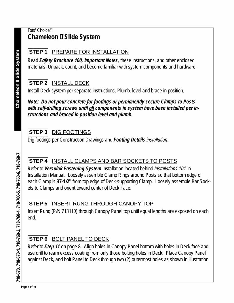
Install Deck system per separate instructions. Plumb, level and brace in position.
Note: Do not pour concrete for footings or permanently secure Clamps to Posts with self-drilling screws until all components in system have been installed per in-structions and braced in position level and plumb.
Dig footings per Construction Drawings and Footing Details installation.
Read Safety Brochure 100, Important Notes, these instructions, and other enclosed materials. Unpack, count, and become familiar with system components and hardware.
STEP 3 DIG FOOTINGS
STEP 2 INSTALL DECK
STEP 1 PREPARE FOR INSTALLATION
Refer to Versalok Fastening System installation located behind Installations 101 in Installation Manual. Loosely assemble Clamp Rings around Posts so that bottom edge of each Clamp is 37-1/2" from top edge of Deck-supporting Clamp. Loosely assemble Bar Sock-ets to Clamps and orient toward center of Deck Face.
STEP 4 INSTALL CLAMPS AND BAR SOCKETS TO POSTS
Insert Rung (P/N 713110) through Canopy Panel top until equal lengths are exposed on each end.
STEP 5 INSERT RUNG THROUGH CANOPY TOP
Refer to Step 11 on page 8. Align holes in Canopy Panel bottom with holes in Deck face and use drill to ream excess coating from only those bolting holes in Deck. Place Canopy Panel against Deck, and bolt Panel to Deck through two (2) outermost holes as shown in illustration.
STEP 6 BOLT PANEL TO DECK

Cha
mel
eon
II Sl
ide
Syst
em
Tots' Choice®
Chameleon II Slide System
Page 5 of 10
718-
670,
718-
670-
1, 71
8-76
0-2,
718-
760-
4, 71
8-76
0-5,
718-
760-
6, 71
8-76
0-7
August 01, 2016
Rev. B
Refer to Versalok Fastening System installation. Place Rung ends into Bar Sockets on Clamps. Ensure that Canopy Panel is plumb and level. Tighten Rung in Bar Sockets with set screws, Bar Sockets on Clamps, and Clamp Rings around Posts.
STEP 7 SET CANOPY RUNG IN BAR SOCKET; TIGHTEN HARDWARE
Arrange Slide sections on ground in "top-down" sequence (starting with Entry section and end-ing with Exit section), according to confi gurations specifi ed in "Construction Drawings." Cha-meleon II Slide Systems may be confi gured in many different ways, therefore it is necessary for proper installation to reference design specifi ed in Construction Drawings.
STEP 8 SET SLIDE SECTIONS IN ORDER
THIS SPACE INTENTIONALLY LEFT BLANK
Page 6 of 10
Cha
mel
eon
II Sl
ide
Syst
em
Tots' Choice®
Chameleon II Slide System
718-
670,
718-
670-
1, 71
8-76
0-2,
718-
760-
4, 71
8-76
0-5,
718-
760-
6, 71
8-76
0-7
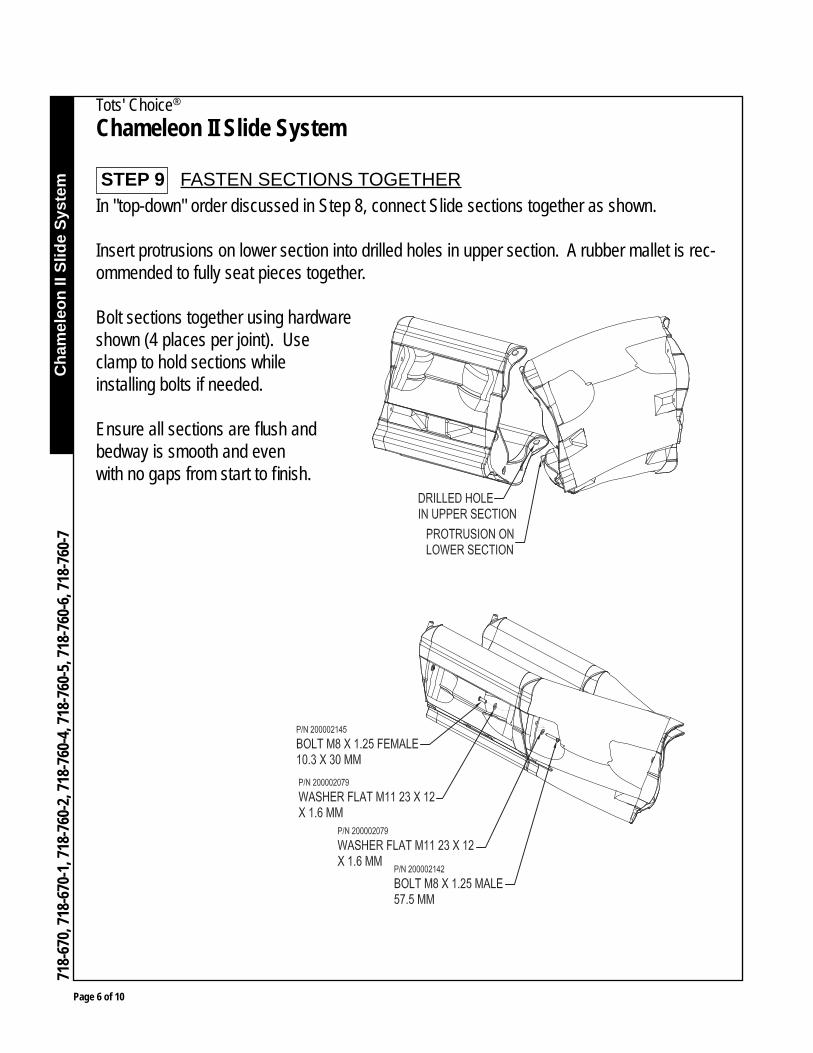
In "top-down" order discussed in Step 8, connect Slide sections together as shown.
Insert protrusions on lower section into drilled holes in upper section. A rubber mallet is rec-ommended to fully seat pieces together.
Bolt sections together using hardware shown (4 places per joint). Use clamp to hold sections while installing bolts if needed.
Ensure all sections are fl ush and bedway is smooth and even with no gaps from start to fi nish.
STEP 9 FASTEN SECTIONS TOGETHER

Cha
mel
eon
II Sl
ide
Syst
em
Tots' Choice®
Chameleon II Slide System
Page 7 of 10
718-
670,
718-
670-
1, 71
8-76
0-2,
718-
760-
4, 71
8-76
0-5,
718-
760-
6, 71
8-76
0-7
August 01, 2016
Rev. B
Assemble Front Leg to Exit section.
Position the Front Leg on the Exit section.Mark the Exit section at the center of the slot on both sides of the Front Leg Bracket.Drill a 1/2" hole at each mark.Attach Front Leg using hardware shown.
STEP 10 ATTACH FRONT LEG
NOTE: Depending on temperature conditions during installation, adjust the Front Leg position on the Exit Section. During hot weather, slide the leg back so that the attachment bolt is in the front half of the slot. During cold weather adjust the leg so that the bolt is in the back half of the slot.

Page 8 of 10
Cha
mel
eon
II Sl
ide
Syst
em
Tots' Choice®
Chameleon II Slide System
718-
670,
718-
670-
1, 71
8-76
0-2,
718-
760-
4, 71
8-76
0-5,
718-
760-
6, 71
8-76
0-7
Position Slide against Canopy Panel and Deck, setting Front Leg into footing. Bolt through Deck and Canopy Panel into Slide at four (4) locations. Bolt through Canopy Panel into Slide's side rails at two (2) locations.
STEP 11 SECURE SLIDE TO DECK
THIS SPACE INTENTIONALLY LEFT BLANK
Cha
mel
eon
II Sl
ide
Syst
em
Tots' Choice®
Chameleon II Slide System
Page 9 of 10
718-
670,
718-
670-
1, 71
8-76
0-2,
718-
760-
4, 71
8-76
0-5,
718-
760-
6, 71
8-76
0-7
August 01, 2016
Rev. B
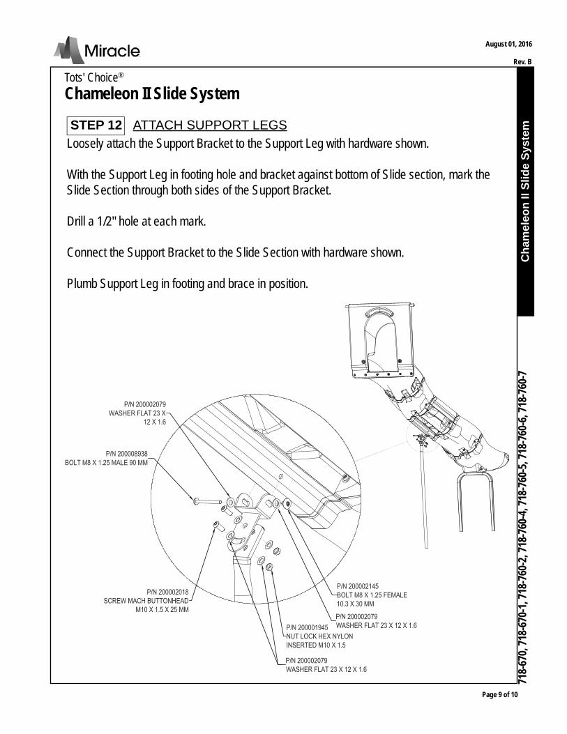
Loosely attach the Support Bracket to the Support Leg with hardware shown.
With the Support Leg in footing hole and bracket against bottom of Slide section, mark the Slide Section through both sides of the Support Bracket.
Drill a 1/2" hole at each mark.
Connect the Support Bracket to the Slide Section with hardware shown.
Plumb Support Leg in footing and brace in position.
STEP 12 ATTACH SUPPORT LEGS

Page 10 of 10
Cha
mel
eon
II Sl
ide
Syst
em
Tots' Choice®
Chameleon II Slide System
718-
670,
718-
670-
1, 71
8-76
0-2,
718-
760-
4, 71
8-76
0-5,
718-
760-
6, 71
8-76
0-7
Proceed with Final Assembly installation. FINAL STEP
Set Slide exit height from fi nished grade as noted and brace in position. Verify that Slide exit will drain water.
STEP 13 SET EXIT HEIGHT

Model 718-706: Square Roof - TierModel 718-861-4: Square Roof - Shingle
718-706
718-861-4
INSTALLATION INSTRUCTIONS
Page 1 of 4
September 8, 2014
Rev. D
Square Roofs
Page 2 of 4
1. Before installing or erecting this equipment, please read and comply with all applicable recom-mendations in Safety Brochure 100 enclosed. If for some reason this brochure is missing,contact your local Miracle sales representative for a copy.
2. Before starting construction, check with all utility companies for exact locations of undergroundutilities.
3. When designing areas for footings and the area under and adjacent to all equipment, consider-ation should be given to soil types and subgrade characteristics. The purchaser and/or installingcontractor will be responsible for proper installation and insuring that abnormal and unsafecompaction does not occur in these areas, which are generally recommended to be under and aminimum of 6' out from the edges of all play structures.
4. It is the purchaser’s responsibility to maintain these areas properly after installation. It is rec-ommended that compaction tests be made several times per year. When compaction occurs, itis recommended that the area affected be scarified or additional pea gravel, sand, redwood barkor coarse wood chips be added until the area is soft and resilient.
IMPORTANT NOTES
September 8, 2014
Rev. D

Square Roofs
Page 3 of 4
STEP 1 For model 718-706, field drill eight (8) 3/8" diameter holes throughroof using brackets as guides and attach each bracket to the roof.
For model 718-706:
STEP 1 For model 718-861-4, attach each bracket to the roof.
Deck must be assembled before roof can be set in place and attached to posts.
(Refer to Roof to Post Detail for your model.)
For model 718-861-4:
ROOF TO POSTDETAIL
MODEL 718-706
ROOF TO POSTDETAIL
MODEL 718-861-4
September 8, 2014
Rev. D
Square Roofs
Page 4 of 4
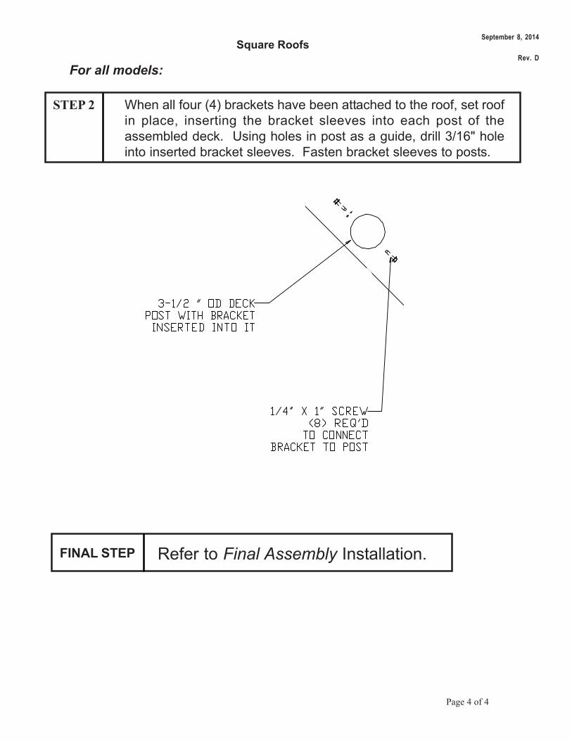
STEP 2 When all four (4) brackets have been attached to the roof, set roofin place, inserting the bracket sleeves into each post of theassembled deck. Using holes in post as a guide, drill 3/16" holeinto inserted bracket sleeves. Fasten bracket sleeves to posts.
For all models:
FINAL STEP Refer to Final Assembly Installation.
September 8, 2014
Rev. D
Vert
ical
Clim
bers
Tots' Choice®
Vertical Climbers
Page 1 of 6
718-
719,
718
-719
-6,
718-
721,
718
-721
-6,
718-
731,
718
-731
-6,
718-
808,
718
-808
-8,
718-
908
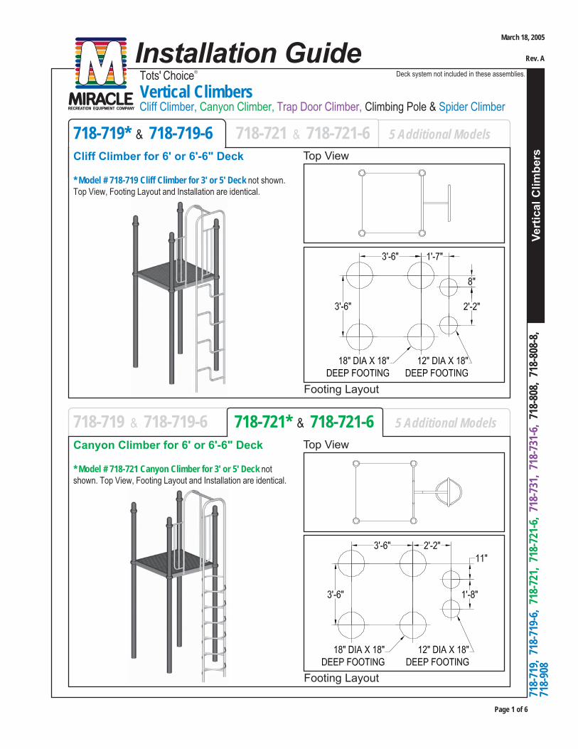
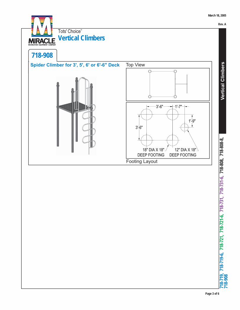
Cliff Climber, Canyon Climber, Trap Door Climber, Climbing Pole & Spider Climber
Installation GuideDeck system not included in these assemblies.
Footing Layout
718-719* & 718-719-6 718-721 & 718-721-6 5 Additional Models
Top ViewCliff Climber for 6' or 6'-6" Deck
* Model # 718-719 Cliff Climber for 3' or 5' Deck not shown.Top View, Footing Layout and Installation are identical.
Footing Layout
718-719 & 718-719-6 718-721* & 718-721-6 5 Additional Models
Top ViewCanyon Climber for 6' or 6'-6" Deck
* Model # 718-721 Canyon Climber for 3' or 5' Deck notshown. Top View, Footing Layout and Installation are identical.
March 18, 2005
Rev. A
Page 2 of 6
Vert
ical
Clim
bers
Tots' Choice®
Vertical Climbers
718-
719,
718-
719-
6, 7
18-7
21,
718-
721-
6, 7
18-7
31,
718-
731-
6, 7
18-8
08,
718-
808-
8,
718-
908
Footing Layout
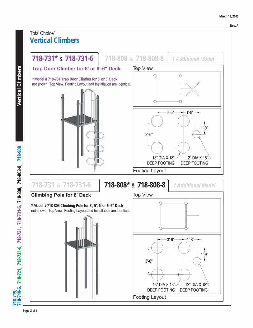
718-731* & 718-731-6 718-808 & 718-808-8 1 Additional Model
Top ViewTrap Door Climber for 6' or 6'-6" Deck
* Model # 718-731 Trap Door Climber for 3' or 5' Decknot shown. Top View, Footing Layout and Installation are identical.
Footing Layout
718-731 & 718-731-6 718-808* & 718-808-8 1 Additional Model
Top ViewClimbing Pole for 8' Deck
* Model # 718-808 Climbing Pole for 3', 5', 6' or 6'-6" Decknot shown. Top View, Footing Layout and Installation are identical.
March 18, 2005
Rev. A
Vert
ical
Clim
bers
Tots' Choice®
Vertical Climbers
Page 3 of 6
718-
719,
718
-719
-6,
718-
721,
718
-721
-6,
718-
731,
718
-731
-6,
718-
808,
718
-808
-8,
718-
908
Footing Layout
718-908Top ViewSpider Climber for 3', 5', 6' or 6'-6" Deck
March 18, 2005
Rev. A

Page 4 of 6
Vert
ical
Clim
bers
Tots' Choice®
Vertical Climbers
718-
719,
718-
719-
6, 7
18-7
21,
718-
721-
6, 7
18-7
31,
718-
731-
6, 7
18-8
08,
718-
808-
8,
718-
908
PARTS IDENTIFICATION
RECOMMENDED ASSEMBLY SEQUENCE1. Deck system (per separate instructions)2. Footing(s)3. Clamps with Bar Sockets loosely to Deck Posts4. Arch Enclosure to Deck and to Posts (via Clamps)5. Climber Assembly into footing(s), to Arch Enclosure6. Final Assembly
1. Concrete for footings, wheelbarrow or mixer, 5 gallon bucket, water supply2. Digging equipment for footings (spade shovel, post hole digger, auger)3. Bracing materials (2x4s, wood pieces, jack stands, sawhorses, concrete blocks, bricks, etc.)4. Tape measure and level5. Open end wrench set, Allen and 6-lobe wrenches or bits, socket set, screwdrivers6. Drill, bits, extension cords, power supply7. Step ladder8. Adult installers - 2 minimum
TOOLS AND EQUIPMENT REQUIREDAlso see 'Suggested Tools & Equipment' (Doc. # D70052) in "Installations 101"
DECK SYSTEM
CLIMBER ASSYARCH ENCLOSURE
VERSALOK CLAMP WITH BAR SOCKET(2) REQ'D
Model # 718-808-8 shown
March 18, 2005
Rev. A
Vert
ical
Clim
bers
Tots' Choice®
Vertical Climbers
Page 5 of 6
718-
719,
718
-719
-6,
718-
721,
718
-721
-6,
718-
731,
718
-731
-6,
718-
808,
718
-808
-8,
718-
908
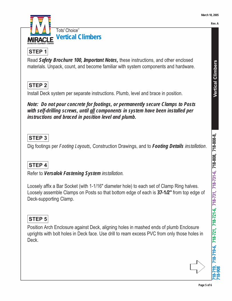
Install Deck system per separate instructions. Plumb, level and brace in position.
Note: Do not pour concrete for footings, or permanently secure Clamps to Postswith self-drilling screws, until all components in system have been installed perinstructions and braced in position level and plumb.
Dig footings per Footing Layouts, Construction Drawings, and to Footing Details installation.
Read Safety Brochure 100, Important Notes, these instructions, and other enclosedmaterials. Unpack, count, and become familiar with system components and hardware.
STEP 3
STEP 2
STEP 1
Refer to Versalok Fastening System installation.
Loosely affix a Bar Socket (with 1-1/16" diameter hole) to each set of Clamp Ring halves.Loosely assemble Clamps on Posts so that bottom edge of each is 37-1/2" from top edge ofDeck-supporting Clamp.
STEP 4
Position Arch Enclosure against Deck, aligning holes in mashed ends of plumb Enclosureuprights with bolt holes in Deck face. Use drill to ream excess PVC from only those holes inDeck.
STEP 5
March 18, 2005
Rev. A
Page 6 of 6
Vert
ical
Clim
bers
Tots' Choice®
Vertical Climbers
718-
719,
718-
719-
6, 7
18-7
21,
718-
721-
6, 7
18-7
31,
718-
731-
6, 7
18-8
08,
718-
808-
8,
718-
908
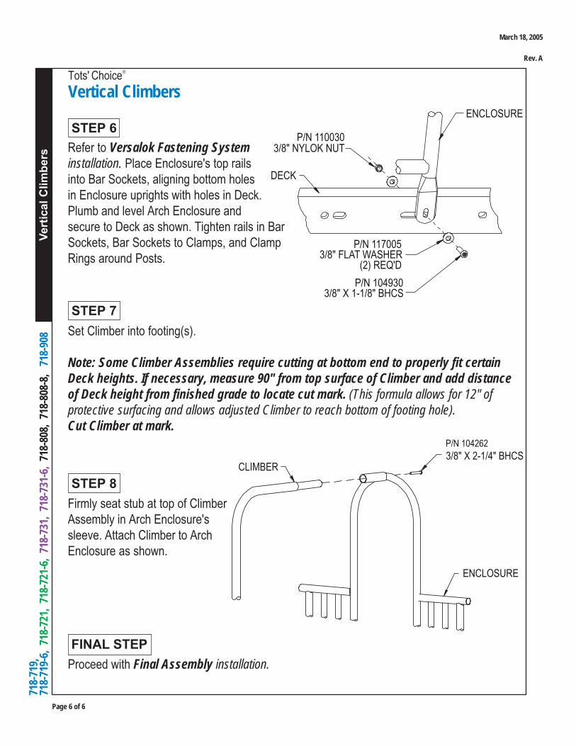
STEP 6
Set Climber into footing(s).
Note: Some Climber Assemblies require cutting at bottom end to properly fit certainDeck heights. If necessary, measure 90" from top surface of Climber and add distanceof Deck height from finished grade to locate cut mark. (This formula allows for 12" ofprotective surfacing and allows adjusted Climber to reach bottom of footing hole).Cut Climber at mark.
STEP 7
Proceed with Final Assembly installation.
FINAL STEP
Refer to Versalok Fastening Systeminstallation. Place Enclosure's top railsinto Bar Sockets, aligning bottom holesin Enclosure uprights with holes in Deck.Plumb and level Arch Enclosure andsecure to Deck as shown. Tighten rails in BarSockets, Bar Sockets to Clamps, and ClampRings around Posts.
Firmly seat stub at top of ClimberAssembly in Arch Enclosure'ssleeve. Attach Climber to ArchEnclosure as shown.
STEP 8
March 18, 2005
Rev. A
Tots' Choice®
Honeycomb Climbers for 4' and 5' Decks
Hon
eyco
mb
Clim
bers
Page 1 of 7
718-755-4
Footing Layout
718-755-5
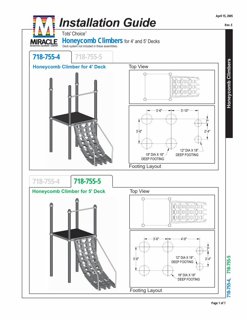
Honeycomb Climber for 5' Deck Top View
Installation GuideDeck system not included in these assemblies.
718-
755-
4,
718
-755
-5
Footing Layout
718-755-4 718-755-5Top ViewHoneycomb Climber for 4' Deck
3'-6" 3'-10"
7"
2'-4"3'-6"
12" DIA X 18"DEEP FOOTING18" DIA X 18"
DEEP FOOTING
3'-6" 4'-9"
7"
2'-4"3'-6" 12" DIA X 18"DEEP FOOTING
18" DIA X 18"DEEP FOOTING
April 15, 2005
Rev. E

Tots' Choice®
Honeycomb Climbers for 4' and 5' Decks
Page 2 of 7
Hon
eyco
mb
Clim
bers
718-
755-
4,
718
-755
-5
RECOMMENDED ASSEMBLY SEQUENCE
1. Deck system (per separate instructions)2. Footings3. Bar Sockets loosely to Clamps, Clamps loosely to Posts4. Chinning Bar to Posts (via Clamps)5. Deck-Climber Bracket to Deck6. Climber sections together with Rungs; Stubs into Climber assembly7. Climber to Deck (Top Rung into Bracket)8. Handholds to Deck and into footings9. Handholds to Stubs on Climber assembly10. Final Assembly
PARTS IDENTIFICATION
DECK
VERSALOK CLAMPAND BAR SOCKET(2) REQ'D
P/N 981765
CHINNING BAR
POST
P/N 984312
BRACKET ASSEMBLY
P/N 720029
TOP RUNG
CLIMBER ASSEMBLY
P/N 984315
HANDHOLD(2) REQ'D
P/N 984313BK
STUB ASSEMBLY
P/N 720033
MID-RUNG
Model # 718-755-5 shown
April 15, 2005
Rev. E
Hon
eyco
mb
Clim
bers
Tots' Choice®
Honeycomb Climbers for 4' and 5' Decks
Page 3 of 7
718-
755-
4,
718
-755
-5
TOOLS AND EQUIPMENT REQUIREDAlso see 'Suggested Tools & Equipment' (Doc. # D70052) in "Installations 101"
1. Concrete for footings, wheelbarrow or mixer, 5 gallon bucket, water supply2. Digging equipment for footing holes (spade shovel, post hole digger, auger)3. Bracing materials (2x4s, wood pieces, jack stands, sawhorses, concrete blocks, bricks, etc.)4. Tape measure and level5. Open end wrench set, Allen and 6-lobe wrenches or bits, socket set, screwdrivers6. Step ladder7. Rubber mallet8. Drill, hex head and 9/16" drill bits, extension cords, power supply9. Adult installers - 2 minimum
April 15, 2005
Rev. E
Tots' Choice®
Honeycomb Climbers for 4' and 5' Decks
Page 4 of 7
Hon
eyco
mb
Clim
bers
718-
755-
4,
718
-755
-5
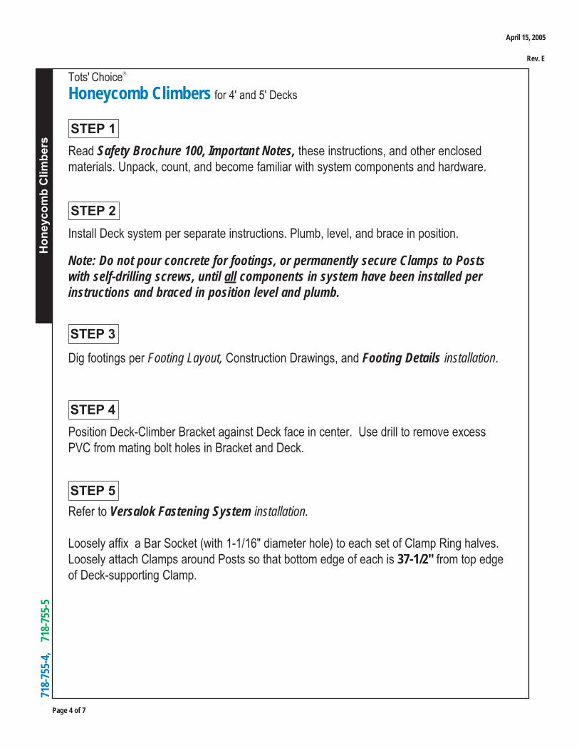
STEP 1Read Safety Brochure 100, Important Notes, these instructions, and other enclosedmaterials. Unpack, count, and become familiar with system components and hardware.
STEP 2
Dig footings per Footing Layout, Construction Drawings, and Footing Details installation.
Install Deck system per separate instructions. Plumb, level, and brace in position.
Note: Do not pour concrete for footings, or permanently secure Clamps to Postswith self-drilling screws, until all components in system have been installed perinstructions and braced in position level and plumb.
STEP 4Position Deck-Climber Bracket against Deck face in center. Use drill to remove excessPVC from mating bolt holes in Bracket and Deck.
Refer to Versalok Fastening System installation.
Loosely affix a Bar Socket (with 1-1/16" diameter hole) to each set of Clamp Ring halves.Loosely attach Clamps around Posts so that bottom edge of each is 37-1/2" from top edgeof Deck-supporting Clamp.
STEP 3
STEP 5
April 15, 2005
Rev. E

Hon
eyco
mb
Clim
bers
Tots' Choice®
Honeycomb Climbers for 4' and 5' Decks
Page 5 of 7
718-
755-
4,
718
-755
-5
P/N 104262
3/8" X 2-1/4" BHCS(2) REQ'D
P/N 117005
3/8" FLAT WASHER(10) REQ'D
HANDHOLD(2) REQ'D
P/N 104930
3/8" X 1-1/8" BHCS(4) REQ'D
P/N 110030
3/8" NYLOK NUT(4) REQ'D
DECKP/N 984312
BRACKET ASSEMBLY
STEP 7Fasten Deck-Climber Bracket to Deck as shown.
STEP 6
Refer to Versalok Fastening System installation.
Place Chinning Bar ends in Bar Sockets. Level Chinning Bar on plumb Posts and tightenBar in Sockets, Sockets on Clamps, and Clamp Rings around Posts.
April 15, 2005
Rev. E

Tots' Choice®
Honeycomb Climbers for 4' and 5' Decks
Page 6 of 7
Hon
eyco
mb
Clim
bers
718-
755-
4,
718
-755
-5
P/N 104404
1/4" X 2" HEX WASHERHD TEK (2) REQ'D
P/N 112719
HONEYCOMB SECTIONP/N 720033
MID-RUNG
FEMALE END
MALE END
Position Honeycomb sections with male and female ends together. Insert Rungs throughsections to connect them, and into top end of Climber assembly (female end.) Gently tapRungs with mallet if necessary to ensure that Rungs are flush with both sides ofHoneycomb sections.
Refer to Step 11 illustration on next page. Tap Stubs into bottom of Climber (male end) withthreaded inserts facing outward.
Attach Honeycomb sections to Mid-Rungs as shown.
Note: Do not affix Honeycomb sections to Top Rung with self-drilling screws.
Note: Top Rung (P/N 720029) has threaded inserts factory-installed in each end,instead of plastic plugs, for mounting to Bracket.
STEP 8
Use drill to ream excess PVC from slots at each end of Deck-Climber Bracket forattachment of Climber. Attach Top Rung of Climber to Bracket using two 3/8" x 1-1/4"BHCS bolts (P/N 104921).
STEP 9
April 15, 2005
Rev. E
Hon
eyco
mb
Clim
bers
Tots' Choice®
Honeycomb Climbers for 4' and 5' Decks
Page 7 of 7
718-
755-
4,
718
-755
-5
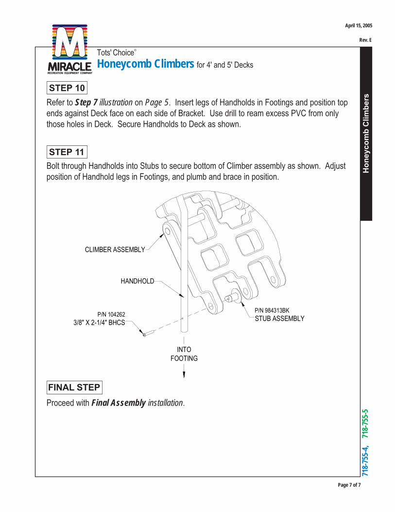
Bolt through Handholds into Stubs to secure bottom of Climber assembly as shown. Adjustposition of Handhold legs in Footings, and plumb and brace in position.
STEP 11
Proceed with Final Assembly installation.
FINAL STEP
Refer to Step 7 illustration on Page 5. Insert legs of Handholds in Footings and position topends against Deck face on each side of Bracket. Use drill to ream excess PVC from onlythose holes in Deck. Secure Handholds to Deck as shown.
STEP 10
INTOFOOTING
HANDHOLD
P/N 984313BK
STUB ASSEMBLY
CLIMBER ASSEMBLY
P/N 104262
3/8" X 2-1/4" BHCS
April 15, 2005
Rev. E
Page 1 of 2
Installation Guide
718-796-P1
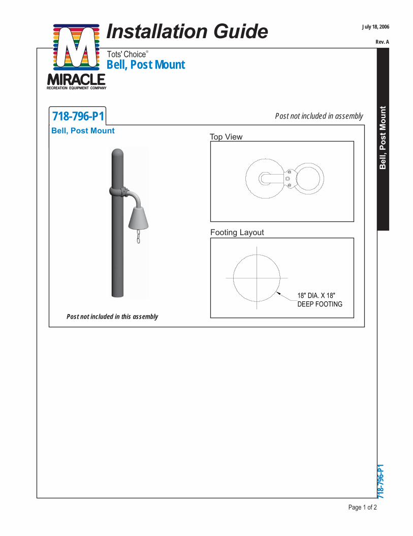
Bell, Post Mount
Bel
l, Po
st M
ount
718-
796-
P1
Footing Layout
Bell, Post MountTop View
Post not included in this assembly
18" DIA. X 18"DEEP FOOTING
Tots' Choice®
Post not included in assembly
July 18, 2006
Rev. A
Page 2 of 2
Installation GuideBell, Post Mount
Bel
l, Po
st M
ount
718-
796-
P1
Tots' Choice®
Read Safety Brochure 100, Important Notes, these instructions, and other materials.Unpack, count and become familiar with system components and hardware.
STEP 1 PREPARE FOR INSTALLATION
STEP 2 ATTACH CLAMP RING AND BAR SOCKET TO POST
Refer to Versalok Fastening System installation guide located behind Installations 101 inyour Installation Manual.
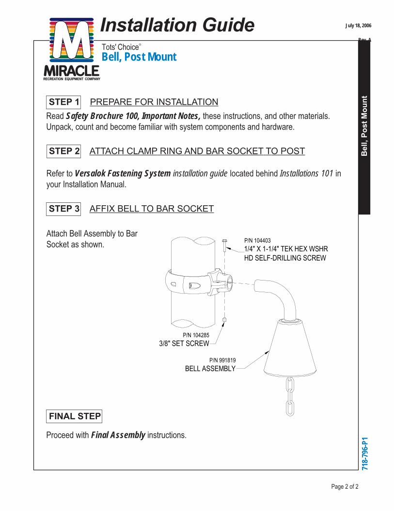
STEP 3 AFFIX BELL TO BAR SOCKET
FINAL STEP
Proceed with Final Assembly instructions.
Attach Bell Assembly to BarSocket as shown.
P/N 104285
3/8" SET SCREW
P/N 104403
1/4" X 1-1/4" TEK HEX WSHRHD SELF-DRILLING SCREW
P/N 991819
BELL ASSEMBLY
July 18, 2006
Rev. A
Installation GuideTots' Choice®
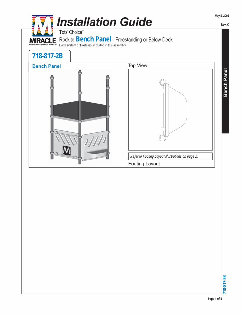
Rockite Bench Panel - Freestanding or Below Deck
Ben
ch P
anel
Page 1 of 4
718-817-2B
Bench Panel
718-
817-
2B
Footing Layout
Top View
Deck system or Posts not included in this assembly.
Refer to Footing Layout illustrations on page 2.
May 5, 2005
Rev. C

Page 2 of 4
Tots' Choice®
Rockite Bench Panel - Freestanding or Below Deck
Ben
ch P
anel
718-
817-
2B
FOOTING LAYOUTS
RECOMMENDED ASSEMBLY SEQUENCE
1. Deck system or Posts (per separate instructions)2. Clamps with Bar Sockets loosely to Posts3. Rungs to Panel4. Rungs to Posts (via Clamps)5. Final Assembly
1. Tape measure and level2. Open end wrench set, Allen and 6-lobe wrenches or bits, socket set, screwdrivers3. Drill, bits, extension cords, power supply4. Mallet5. Adult installers - 2 minimum
TOOLS AND EQUIPMENT REQUIREDAlso see "Suggested Tools & Equipment" (Doc. # D75002) in "Installations 101"
Freestanding or BelowDeck (one unit)
Sample of ClusteredArrangement (multipleunits)
18" DIA X 18"DEEP FOOTING
(2) REQ'D
3' 6"
18" DIA X 18"DEEP FOOTING
(5) REQ'D
3' 6" 3' 6"
3' 6"
3' 6"
May 5, 2005
Rev. C
Tots' Choice®
Rockite Bench Panel - Freestanding or Below Deck
Ben
ch P
anel
Page 3 of 4
718-
817-
2B
STEP 1
STEP 2
STEP 3
Read Safety Brochure 100, Important Notes, these instructions, and other enclosedmaterials. Unpack, count, and become familiar with system components and hardware.
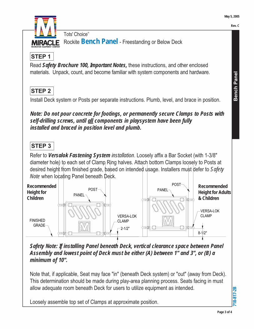
Refer to Versalok Fastening System installation. Loosely affix a Bar Socket (with 1-3/8"diameter hole) to each set of Clamp Ring halves. Attach bottom Clamps loosely to Posts atdesired height from finished grade, based on intended usage. Installers must defer to SafetyNote when locating Panel beneath Deck.
Safety Note: If installing Panel beneath Deck, vertical clearance space between PanelAssembly and lowest point of Deck must be either (A) between 1" and 3", or (B) aminimum of 10".
Note that, if applicable, Seat may face "in" (beneath Deck system) or "out" (away from Deck).This determination should be made during play-area planning process. Seats facing in mustallow adequate room beneath Deck for users to utilize equipment as intended.
Loosely assemble top set of Clamps at approximate position.
Install Deck system or Posts per separate instructions. Plumb, level, and brace in position.
Note: Do not pour concrete for footings, or permanently secure Clamps to Posts withself-drilling screws, until all components in playsystem have been fullyinstalled and braced in position level and plumb.
2-1/2"
POST
PANEL
VERSA-LOKCLAMPFINISHED
GRADE
POST
PANEL
VERSA-LOKCLAMP
8-1/2"
RecommendedHeight forChildren
RecommendedHeight for Adults& Children
May 5, 2005
Rev. C

Page 4 of 4
Tots' Choice®
Rockite Bench Panel - Freestanding or Below Deck
Ben
ch P
anel
718-
817-
2B
Use mallet to tap Rungs into Panel, leaving equal amounts of Rung exposed on each end.
Proceed with Final Assembly installation.
STEP 4
STEP 5
FINAL STEP
Refer to Versalok Fastening System installation. Insert ends of Rungs in Bar Sockets on topand bottom sets of Clamps, repositioning Clamps as needed.
Make certain Panel is centered between Posts. If Panel is installed beneath Deck, verify thatcondition of Safety Note (Step 3, Page 3) has been satisfied.
Level Panel Assembly. Tighten Rungs in Bar Sockets, Bar Sockets on Clamps, and ClampRings around Posts.
Center Panel Assembly on Rungs between Posts. Install two (2) 1/4" x 1-1/4" self-drillingscrews (P/N 104403) at recessed areas of Panel flanges into bottom Rung to fix position ofPanel.
STEP 6
May 5, 2005
Rev. C
Squa
re T
rans
fer P
oint
s
Page 1 of 24
August 22, 2017
Rev. C
718-
851-
39, 7
18-8
51-3
59, 7
18-8
51-4
9, 7
18-8
51-4
59, 7
18-8
51-5
9, 71
8-85
1-69
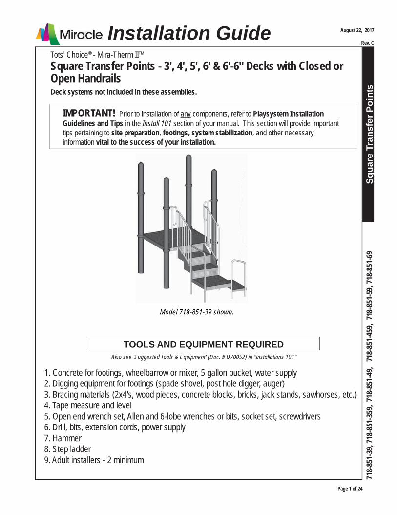
Tots' Choice® - Mira-Therm II™Square Transfer Points - 3', 4', 5', 6' & 6'-6" Decks with Closed or Open HandrailsDeck systems not included in these assemblies.
Installation Guide
IMPORTANT! Prior to installation of any components, refer to Playsystem Installation Guidelines and Tips in the Install 101 section of your manual. This section will provide important tips pertaining to site preparation, footings, system stabilization, and other necessary information vital to the success of your installation.
1. Concrete for footings, wheelbarrow or mixer, 5 gallon bucket, water supply2. Digging equipment for footings (spade shovel, post hole digger, auger)3. Bracing materials (2x4's, wood pieces, concrete blocks, bricks, jack stands, sawhorses, etc.)4. Tape measure and level5. Open end wrench set, Allen and 6-lobe wrenches or bits, socket set, screwdrivers6. Drill, bits, extension cords, power supply7. Hammer8. Step ladder9. Adult installers - 2 minimum
TOOLS AND EQUIPMENT REQUIREDAlso see 'Suggested Tools & Equipment' (Doc. # D70052) in "Installations 101"
Model 718-851-39 shown.
Page 2 of 24
Squa
re T
rans
fer P
oint
s
Tots' Choice® - Mira-Therm II™Square Transfer Points - 3', 4', 5', 6' & 6'-6" Decks with Closed or Open HandrailsDeck systems not included in these assemblies.
August 22, 2017
Rev. C
718-
851-
39, 7
18-8
51-3
59, 7
18-8
51-4
9, 7
18-8
51-4
59, 7
18-8
51-5
9, 71
8-85
1-69
Footing Layout
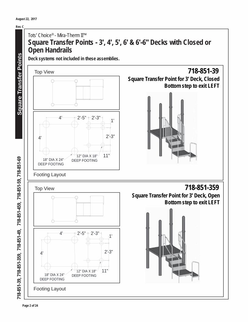
718-851-39Top ViewSquare Transfer Point for 3' Deck, Closed
Bottom step to exit LEFT
4'
4'
2'-5" 2'-3" 1'
2'-3"
11"18" DIA X 24"
DEEP FOOTING
12" DIA X 18"DEEP FOOTING
Footing Layout
718-851-359Top ViewSquare Transfer Point for 3' Deck, Open
Bottom step to exit LEFT
4'
4'
2'-5" 2'-3" 1'
2'-3"
11"18" DIA X 24"
DEEP FOOTING
12" DIA X 18"DEEP FOOTING
Squa
re T
rans
fer P
oint
s
Page 3 of 24
August 22, 2017
Rev. C
718-
851-
39, 7
18-8
51-3
59, 7
18-8
51-4
9, 7
18-8
51-4
59, 7
18-8
51-5
9, 71
8-85
1-69
Tots' Choice® - Mira-Therm II™Square Transfer Points - 3', 4', 5', 6' & 6'-6" Decks with Closed or Open HandrailsDeck systems not included in these assemblies.
Footing Layout
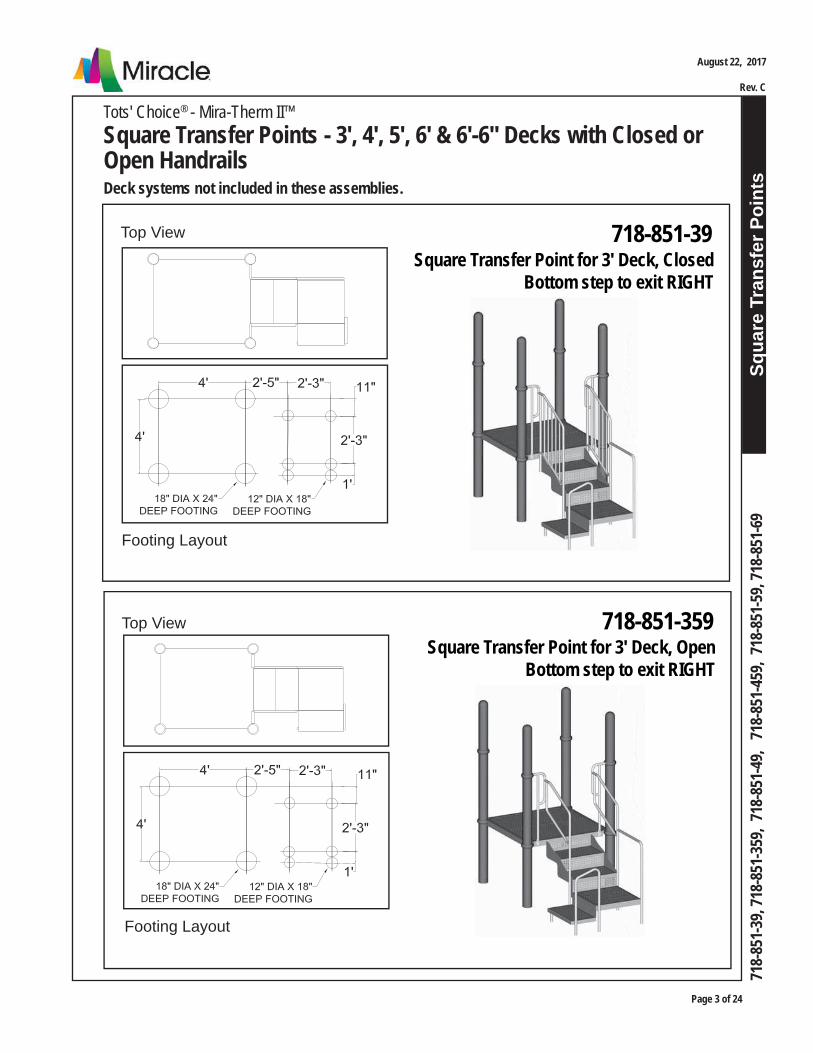
Top View 718-851-39Square Transfer Point for 3' Deck, Closed
Bottom step to exit RIGHT
Footing Layout
Top View 718-851-359Square Transfer Point for 3' Deck, Open
Bottom step to exit RIGHT
Page 4 of 24
Squa
re T
rans
fer P
oint
s
Tots' Choice® - Mira-Therm II™Square Transfer Points - 3', 4', 5', 6' & 6'-6" Decks with Closed or Open HandrailsDeck systems not included in these assemblies.
August 22, 2017
Rev. C
718-
851-
39, 7
18-8
51-3
59, 7
18-8
51-4
9, 7
18-8
51-4
59, 7
18-8
51-5
9, 71
8-85
1-69
Footing Layout
Top View
4' 2'-5" 2'-3"1'
4'
11"
2'-3"
18" DIA X 24"DEEP FOOTING
12" DIA X 18"DEEP FOOTING
718-851-39Square Transfer Point for 3' Deck, Closed
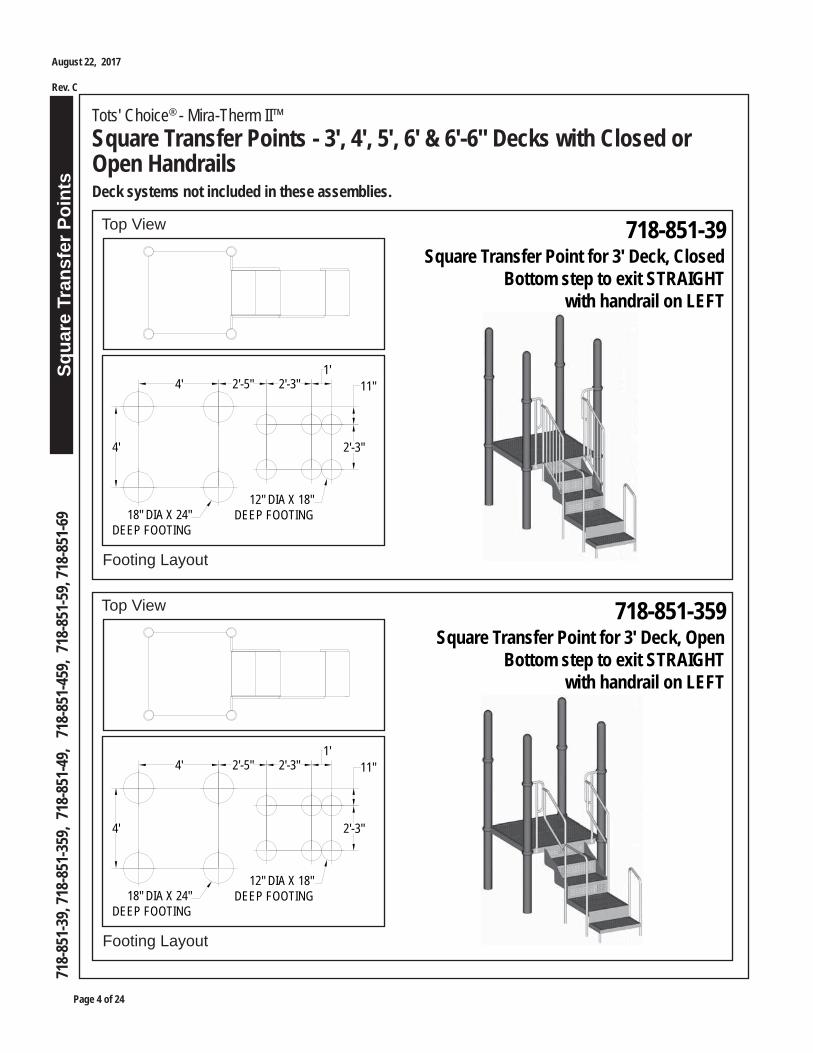
Bottom step to exit STRAIGHT with handrail on LEFT
Footing Layout
Top View
4' 2'-5" 2'-3"1'
4'
11"
2'-3"
18" DIA X 24"DEEP FOOTING
12" DIA X 18"DEEP FOOTING
718-851-359Square Transfer Point for 3' Deck, Open
Bottom step to exit STRAIGHT with handrail on LEFT
Squa
re T
rans
fer P
oint
s
Page 5 of 24
August 22, 2017
Rev. C
718-
851-
39, 7
18-8
51-3
59, 7
18-8
51-4
9, 7
18-8
51-4
59, 7
18-8
51-5
9, 71
8-85
1-69
Tots' Choice® - Mira-Therm II™Square Transfer Points - 3', 4', 5', 6' & 6'-6" Decks with Closed or Open HandrailsDeck systems not included in these assemblies.
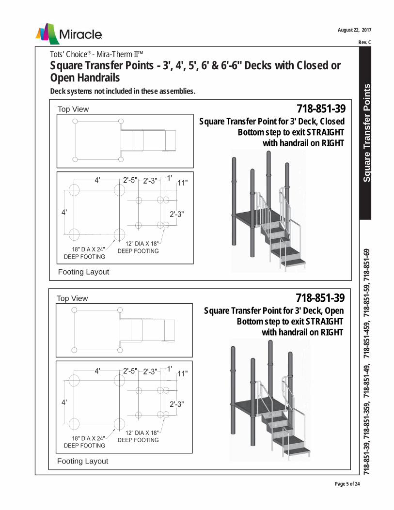
Footing Layout
Top View 718-851-39Square Transfer Point for 3' Deck, Closed
Bottom step to exit STRAIGHT with handrail on RIGHT
Footing Layout
Top View 718-851-39Square Transfer Point for 3' Deck, Open
Bottom step to exit STRAIGHT with handrail on RIGHT
Page 6 of 24
Squa
re T
rans
fer P
oint
s
Tots' Choice® - Mira-Therm II™Square Transfer Points - 3', 4', 5', 6' & 6'-6" Decks with Closed or Open HandrailsDeck systems not included in these assemblies.
August 22, 2017
Rev. C
718-
851-
39, 7
18-8
51-3
59, 7
18-8
51-4
9, 7
18-8
51-4
59, 7
18-8
51-5
9, 71
8-85
1-69
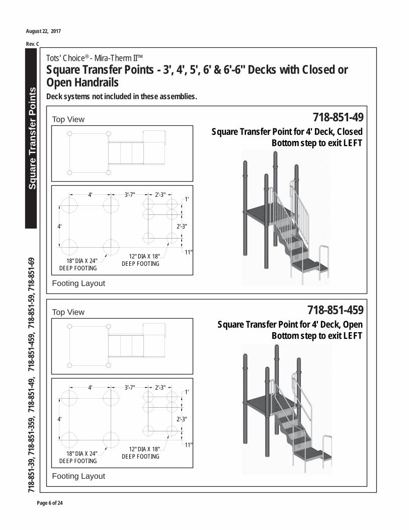
Footing Layout
718-851-49Top View
4' 3'-7" 2'-3"1'
2'-3"
11"
4'
18" DIA X 24"DEEP FOOTING
12" DIA X 18"DEEP FOOTING
Square Transfer Point for 4' Deck, ClosedBottom step to exit LEFT
Footing Layout
718-851-459Top View
4' 3'-7" 2'-3"1'
2'-3"
11"
4'
18" DIA X 24"DEEP FOOTING
12" DIA X 18"DEEP FOOTING
Square Transfer Point for 4' Deck, OpenBottom step to exit LEFT

Squa
re T
rans
fer P
oint
s
Page 7 of 24
August 22, 2017
Rev. C
718-
851-
39, 7
18-8
51-3
59, 7
18-8
51-4
9, 7
18-8
51-4
59, 7
18-8
51-5
9, 71
8-85
1-69
Tots' Choice® - Mira-Therm II™Square Transfer Points - 3', 4', 5', 6' & 6'-6" Decks with Closed or Open HandrailsDeck systems not included in these assemblies.
Footing Layout
718-851-49Top ViewSquare Transfer Point for 4' Deck, Closed
Bottom step to exit RIGHT
Footing Layout
718-851-459Top ViewSquare Transfer Point for 4' Deck, Open
Bottom step to exit RIGHT
Page 8 of 24
Squa
re T
rans
fer P
oint
s
Tots' Choice® - Mira-Therm II™Square Transfer Points - 3', 4', 5', 6' & 6'-6" Decks with Closed or Open HandrailsDeck systems not included in these assemblies.
August 22, 2017
Rev. C
718-
851-
39, 7
18-8
51-3
59, 7
18-8
51-4
9, 7
18-8
51-4
59, 7
18-8
51-5
9, 71
8-85
1-69
Footing Layout
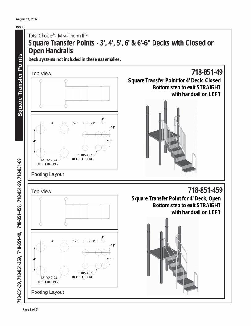
718-851-49Top ViewSquare Transfer Point for 4' Deck, Closed
Bottom step to exit STRAIGHT with handrail on LEFT
4' 3'-7" 2'-3"1'
4'
11"
2'-3"
18" DIA X 24"DEEP FOOTING
12" DIA X 18"DEEP FOOTING
Footing Layout
718-851-459Top ViewSquare Transfer Point for 4' Deck, Open
Bottom step to exit STRAIGHT with handrail on LEFT
4' 3'-7" 2'-3"1'
4'
11"
2'-3"
18" DIA X 24"DEEP FOOTING
12" DIA X 18"DEEP FOOTING
Squa
re T
rans
fer P
oint
s
Page 9 of 24
August 22, 2017
Rev. C
718-
851-
39, 7
18-8
51-3
59, 7
18-8
51-4
9, 7
18-8
51-4
59, 7
18-8
51-5
9, 71
8-85
1-69
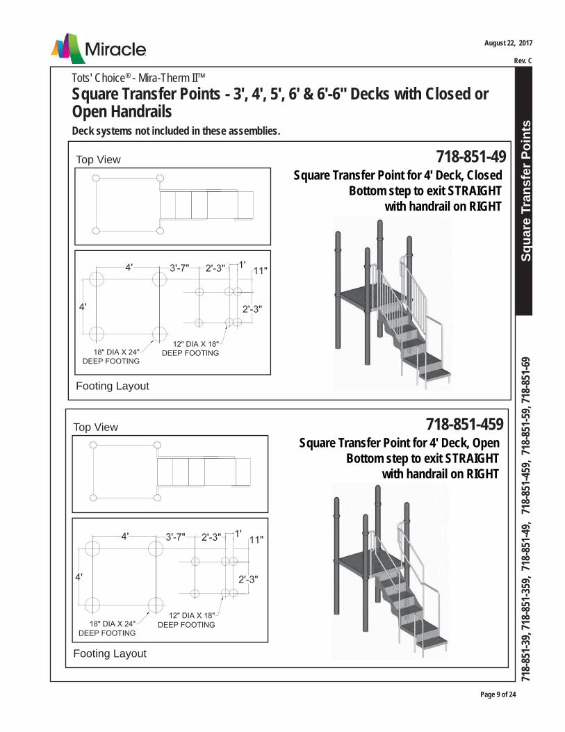
Tots' Choice® - Mira-Therm II™Square Transfer Points - 3', 4', 5', 6' & 6'-6" Decks with Closed or Open HandrailsDeck systems not included in these assemblies.
Footing Layout
718-851-49Top ViewSquare Transfer Point for 4' Deck, Closed
Bottom step to exit STRAIGHT with handrail on RIGHT
Footing Layout
718-851-459Top ViewSquare Transfer Point for 4' Deck, Open
Bottom step to exit STRAIGHT with handrail on RIGHT

Page 10 of 24
Squa
re T
rans
fer P
oint
s
Tots' Choice® - Mira-Therm II™Square Transfer Points - 3', 4', 5', 6' & 6'-6" Decks with Closed or Open HandrailsDeck systems not included in these assemblies.
August 22, 2017
Rev. C
718-
851-
39, 7
18-8
51-3
59, 7
18-8
51-4
9, 7
18-8
51-4
59, 7
18-8
51-5
9, 71
8-85
1-69
Footing Layout
718-851-59Top ViewSquare Transfer Point for 5' Deck, Closed
Bottom step to exit LEFT
Footing Layout
718-851-59Top ViewSquare Transfer Point for 5' Deck, Closed
Bottom step to exit RIGHT
4' 5'-11" 2'-3"
4'
11"
2'-3"
1'
18" DIA X 24"DEEP FOOTING
12" DIA X 18"DEEP FOOTING
4' 5'-11" 2'-3"
4'
11"
2'-3"
1'18" DIA X 24"DEEP FOOTING
12" DIA X 18"DEEP FOOTING
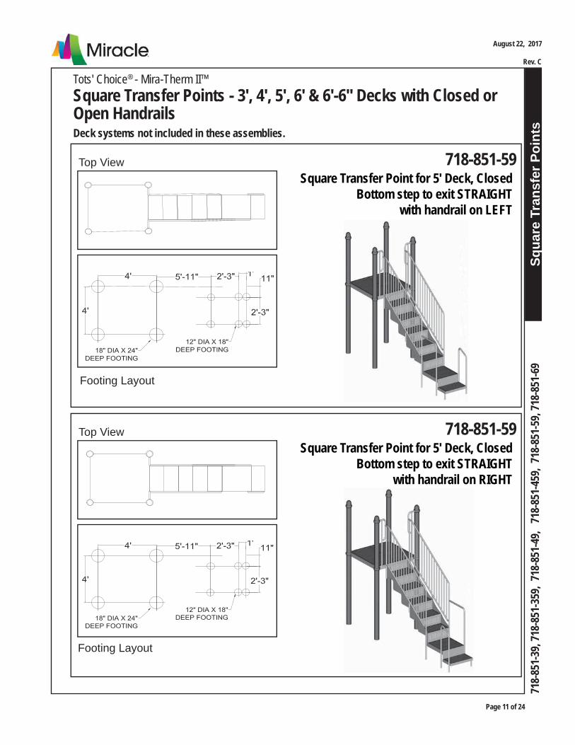
Squa
re T
rans
fer P
oint
s
Page 11 of 24
August 22, 2017
Rev. C
718-
851-
39, 7
18-8
51-3
59, 7
18-8
51-4
9, 7
18-8
51-4
59, 7
18-8
51-5
9, 71
8-85
1-69
Tots' Choice® - Mira-Therm II™Square Transfer Points - 3', 4', 5', 6' & 6'-6" Decks with Closed or Open HandrailsDeck systems not included in these assemblies.
Footing Layout
718-851-59Top ViewSquare Transfer Point for 5' Deck, Closed
Bottom step to exit STRAIGHT with handrail on LEFT
Footing Layout
718-851-59Top ViewSquare Transfer Point for 5' Deck, Closed
Bottom step to exit STRAIGHT with handrail on RIGHT
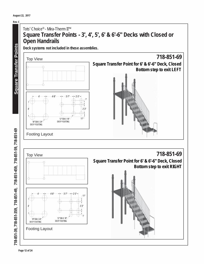
Page 12 of 24
Squa
re T
rans
fer P
oint
s
Tots' Choice® - Mira-Therm II™Square Transfer Points - 3', 4', 5', 6' & 6'-6" Decks with Closed or Open HandrailsDeck systems not included in these assemblies.
August 22, 2017
Rev. C
718-
851-
39, 7
18-8
51-3
59, 7
18-8
51-4
9, 7
18-8
51-4
59, 7
18-8
51-5
9, 71
8-85
1-69
Footing Layout
718-851-69Top ViewSquare Transfer Point for 6' & 6'-6" Deck, Closed
Bottom step to exit LEFT
Footing Layout
718-851-69Top View
4' 4'-8" 3'-7" 2'-3"
11"
2'-3"
1'
4'
18" DIA X 24"DEEP FOOTING
12" DIA X 18"DEEP FOOTING
Square Transfer Point for 6' & 6'-6" Deck, ClosedBottom step to exit RIGHT
18" DIA X 24"DEEP FOOTING
12" DIA X 18"DEEP FOOTING
4' 4'-8" 3'-7" 2'-3"11"
2'-3"
1'
4'
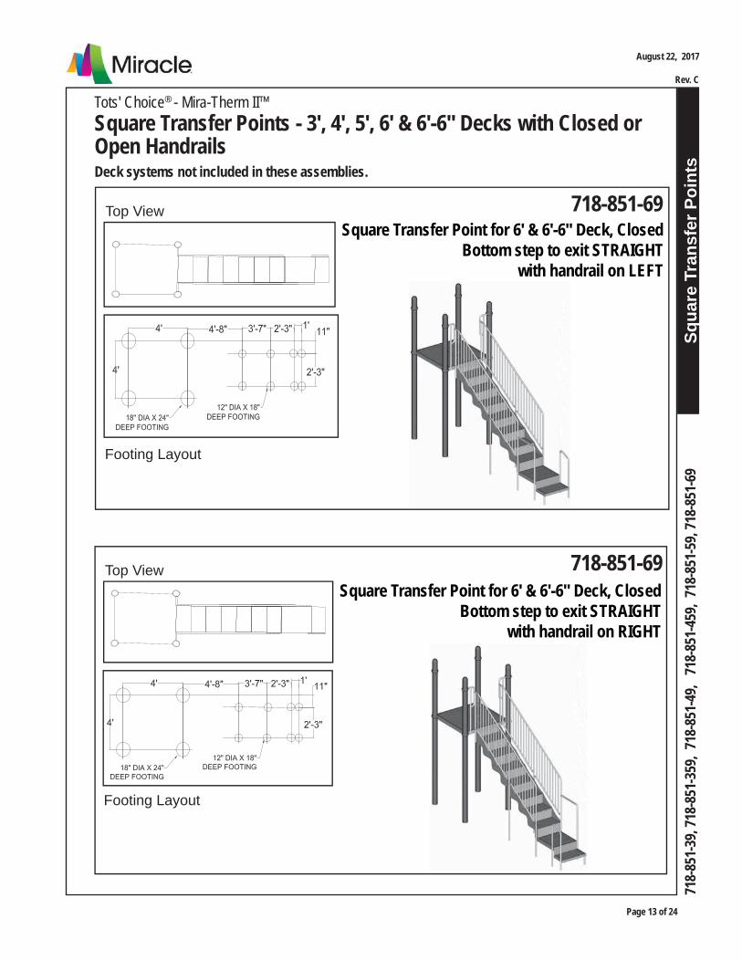
Squa
re T
rans
fer P
oint
s
Page 13 of 24
August 22, 2017
Rev. C
718-
851-
39, 7
18-8
51-3
59, 7
18-8
51-4
9, 7
18-8
51-4
59, 7
18-8
51-5
9, 71
8-85
1-69
Tots' Choice® - Mira-Therm II™Square Transfer Points - 3', 4', 5', 6' & 6'-6" Decks with Closed or Open HandrailsDeck systems not included in these assemblies.
Footing Layout
718-851-69Top ViewSquare Transfer Point for 6' & 6'-6" Deck, Closed
Bottom step to exit STRAIGHT with handrail on LEFT
Footing Layout
718-851-69Top ViewSquare Transfer Point for 6' & 6'-6" Deck, Closed
Bottom step to exit STRAIGHT with handrail on RIGHT

Page 14 of 24
Squa
re T
rans
fer P
oint
s
Tots' Choice® - Mira-Therm II™Square Transfer Points - 3', 4', 5', 6' & 6'-6" Decks with Closed or Open HandrailsDeck systems not included in these assemblies.
August 22, 2017
Rev. C
718-
851-
39, 7
18-8
51-3
59, 7
18-8
51-4
9, 7
18-8
51-4
59, 7
18-8
51-5
9, 71
8-85
1-69
RECOMMENDED ASSEMBLY SEQUENCE
1. Deck system (per separate instructions)2. Footings3. Deck enclosures to deck and to posts (via clamps and bar sockets)4. Stair handrail and stair/deck handrail to deck enclosures 5. Swaged extensions (and sleeves if applicable) to stair handrail and stair/deck handrail (extensions into footings)6. Stair to deck and to handrails (via sleeves if applicable)7. Transfer point deck to stair8. Transfer deck handrail to stair/deck handrail and transfer point deck (transfer deck handrail into footing)9. Transfer step handrail to transfer point deck (transfer step handrail into footings)10. Bottom step to transfer point deck and transfer step handrail11. Rung leg to bottom step (rung leg into footing)12. Final assembly
2a. Install deck system per separate instructions. Plumb, level and brace in position.
Note: Do not pour concrete for footings, or permanently secure clamps to posts with self-drilling screws, until all components in system have been installed per instructions and braced in posi-tion, level and plumb.
3a. Dig footings per Footing Layout, Construction Drawings, and Footing Details installation.
1a. Read Safety Brochure 100, Important Notes, these instructions, and other enclosed materials. Unpack, count, and become familiar with system components and hardware.
STEP 3
STEP 2
STEP 1
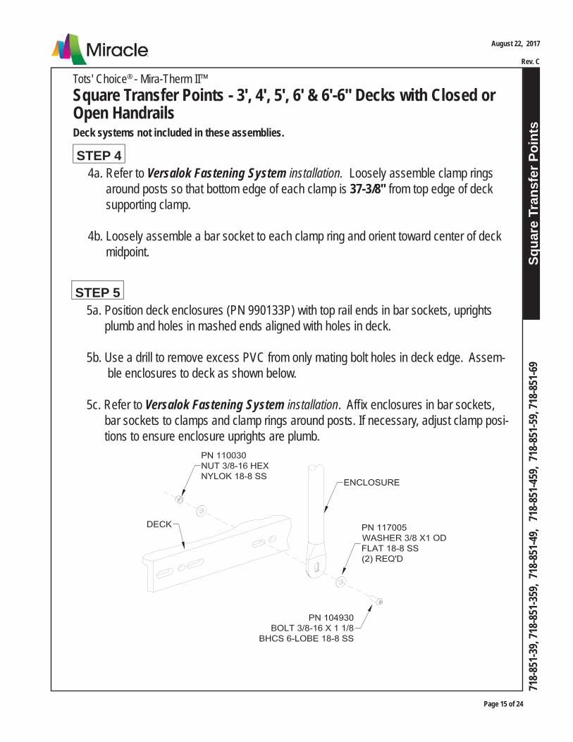
Squa
re T
rans
fer P
oint
s
Page 15 of 24
August 22, 2017
Rev. C
718-
851-
39, 7
18-8
51-3
59, 7
18-8
51-4
9, 7
18-8
51-4
59, 7
18-8
51-5
9, 71
8-85
1-69
Tots' Choice® - Mira-Therm II™Square Transfer Points - 3', 4', 5', 6' & 6'-6" Decks with Closed or Open HandrailsDeck systems not included in these assemblies.
4a. Refer to Versalok Fastening System installation. Loosely assemble clamp rings around posts so that bottom edge of each clamp is 37-3/8" from top edge of deck supporting clamp.
4b. Loosely assemble a bar socket to each clamp ring and orient toward center of deck midpoint.
STEP 4
5a. Position deck enclosures (PN 990133P) with top rail ends in bar sockets, uprights plumb and holes in mashed ends aligned with holes in deck.
5b. Use a drill to remove excess PVC from only mating bolt holes in deck edge. Assem- ble enclosures to deck as shown below.
5c. Refer to Versalok Fastening System installation. Affi x enclosures in bar sockets, bar sockets to clamps and clamp rings around posts. If necessary, adjust clamp posi- tions to ensure enclosure uprights are plumb.
STEP 5

Page 16 of 24
Squa
re T
rans
fer P
oint
s
Tots' Choice® - Mira-Therm II™Square Transfer Points - 3', 4', 5', 6' & 6'-6" Decks with Closed or Open HandrailsDeck systems not included in these assemblies.
August 22, 2017
Rev. C
718-
851-
39, 7
18-8
51-3
59, 7
18-8
51-4
9, 7
18-8
51-4
59, 7
18-8
51-5
9, 71
8-85
1-69
6a. Refer to Construction Drawing Top View to determine planned orientation of transfer point's bottom step and transfer step handrail, which establishes correct location for stair handrail and stair/deck handrail (i.e. which side of stair assembly to install each).
Note: Transfer handrail contains a bolt hole in its bottom upright for assembly of transfer deck handrail, while stair handrail does not contain the hole.
6b. Assemble top ends of handrails to deck enclosures as shown. Support handrails until next step is complete.
STEP 6
For models from 5' and 6'-6" Decks only:
7a. Refer to step 12 or step 13 illustration. Place handrail sleeves on lower upright of stair handrail and stair/deck handrail and loosely insert a bolt into one hole, to hold sleeve above connection point of handrail extension (per next instruction). Repeat for middle uprights for model 718-851-59 only.
STEP 7

Squa
re T
rans
fer P
oint
s
Page 17 of 24
August 22, 2017
Rev. C
718-
851-
39, 7
18-8
51-3
59, 7
18-8
51-4
9, 7
18-8
51-4
59, 7
18-8
51-5
9, 71
8-85
1-69
Tots' Choice® - Mira-Therm II™Square Transfer Points - 3', 4', 5', 6' & 6'-6" Decks with Closed or Open HandrailsDeck systems not included in these assemblies.
For ALL models:
7b. Set handrail extensions into footings beneath uprights of stair handrail and stair/deck handrail. Insert and fully seat swaged ends of extensions into lower handrail uprights and middle uprights for model 718-851-69 only.
7c. Plumb assemblies and drill a 1/4" hole through handrails into exten- sions. Fully seat a drive rivet in each and strike pin with hammer to expand.
STEP 7, cont.
8a. Use a drill to remove excess PVC from four (4) bolt holes in both top and bottom ends of stair, for attachment to deck and transfer point deck, and from holes on both sides of stair for handrail attachment.
8b. Remove excess PVC from mating bolt holes in deck edge and two faces of transfer point deck for attachment to stair and bottom step.
STEP 8
THIS SPACE INTENTIONALLY LEFT BLANK

Page 18 of 24
Squa
re T
rans
fer P
oint
s
Tots' Choice® - Mira-Therm II™Square Transfer Points - 3', 4', 5', 6' & 6'-6" Decks with Closed or Open HandrailsDeck systems not included in these assemblies.
August 22, 2017
Rev. C
718-
851-
39, 7
18-8
51-3
59, 7
18-8
51-4
9, 7
18-8
51-4
59, 7
18-8
51-5
9, 71
8-85
1-69
9a. Position top end of stair against deck and assemble as shown.
Note: Do not tighten bolts in this assembly until all parts are fully installed and braced in position, level and plumb.
STEP 9
For models with Closed (Spoked) Handrails only:
10a. Assemble topmost upright on handrails to stair sides as shown. Assemble middle upright on handrails to stair sides as shown for model 718-851-59 only.
STEP 10
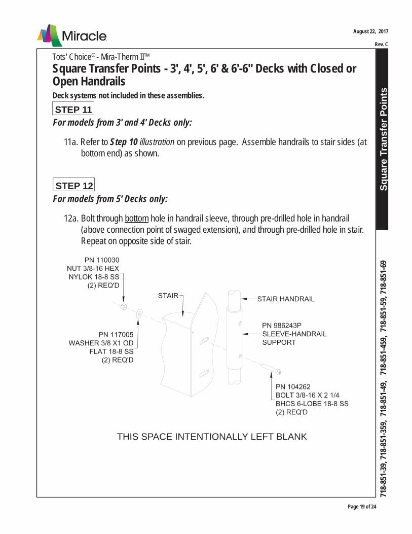
Squa
re T
rans
fer P
oint
s
Page 19 of 24
August 22, 2017
Rev. C
718-
851-
39, 7
18-8
51-3
59, 7
18-8
51-4
9, 7
18-8
51-4
59, 7
18-8
51-5
9, 71
8-85
1-69
Tots' Choice® - Mira-Therm II™Square Transfer Points - 3', 4', 5', 6' & 6'-6" Decks with Closed or Open HandrailsDeck systems not included in these assemblies.
For models from 5' Decks only:
12a. Bolt through bottom hole in handrail sleeve, through pre-drilled hole in handrail (above connection point of swaged extension), and through pre-drilled hole in stair. Repeat on opposite side of stair.
STEP 12
For models from 3' and 4' Decks only:
11a. Refer to Step 10 illustration on previous page. Assemble handrails to stair sides (at bottom end) as shown.
STEP 11
THIS SPACE INTENTIONALLY LEFT BLANK
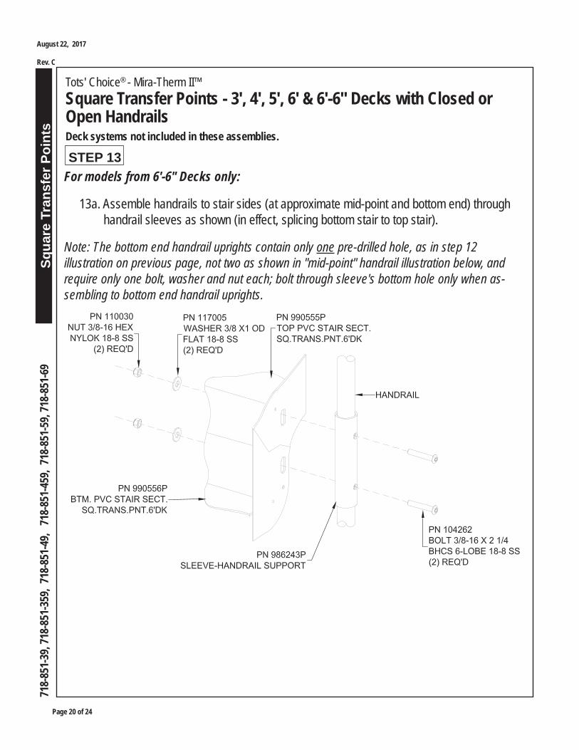
Page 20 of 24
Squa
re T
rans
fer P
oint
s
Tots' Choice® - Mira-Therm II™Square Transfer Points - 3', 4', 5', 6' & 6'-6" Decks with Closed or Open HandrailsDeck systems not included in these assemblies.
August 22, 2017
Rev. C
718-
851-
39, 7
18-8
51-3
59, 7
18-8
51-4
9, 7
18-8
51-4
59, 7
18-8
51-5
9, 71
8-85
1-69
STEP 13For models from 6'-6" Decks only:
13a. Assemble handrails to stair sides (at approximate mid-point and bottom end) through handrail sleeves as shown (in effect, splicing bottom stair to top stair).
Note: The bottom end handrail uprights contain only one pre-drilled hole, as in step 12 illustration on previous page, not two as shown in "mid-point" handrail illustration below, and require only one bolt, washer and nut each; bolt through sleeve's bottom hole only when as-sembling to bottom end handrail uprights.
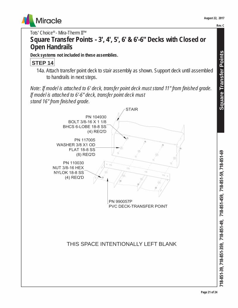
Squa
re T
rans
fer P
oint
s
Page 21 of 24
August 22, 2017
Rev. C
718-
851-
39, 7
18-8
51-3
59, 7
18-8
51-4
9, 7
18-8
51-4
59, 7
18-8
51-5
9, 71
8-85
1-69
Tots' Choice® - Mira-Therm II™Square Transfer Points - 3', 4', 5', 6' & 6'-6" Decks with Closed or Open HandrailsDeck systems not included in these assemblies.
14a. Attach transfer point deck to stair assembly as shown. Support deck until assembled to handrails in next steps.
Note: If model is attached to 6' deck, transfer point deck must stand 11" from fi nished grade. If model is attached to 6'-6" deck, transfer point deck must stand 16" from fi nished grade.
STEP 14
THIS SPACE INTENTIONALLY LEFT BLANK

Page 22 of 24
Squa
re T
rans
fer P
oint
s
Tots' Choice® - Mira-Therm II™Square Transfer Points - 3', 4', 5', 6' & 6'-6" Decks with Closed or Open HandrailsDeck systems not included in these assemblies.
August 22, 2017
Rev. C
718-
851-
39, 7
18-8
51-3
59, 7
18-8
51-4
9, 7
18-8
51-4
59, 7
18-8
51-5
9, 71
8-85
1-69
16a. Refer to pertinent model illustration from pages 1 - 8. Locate bolt holes on sides of transfer point deck that mate with bolt holes in transfer deck handrail and transfer step handrail. Use a drill to remove excess PVC from them.
STEP 16
17a. Refer to step 10 illustration on page 18. Attach transfer point deck to transfer deck handrail.
STEP 17
18a. Refer to step 10 illustration on page 18. Place legs of transfer step handrail into foot- ing holes, with longer leg (higher arch) oriented toward transfer point deck. Fasten longer leg of transfer step handrail to transfer point deck.
STEP 18
15a. Set transfer deck handrail leg into footing and fasten top end to stair/deck handrail as shown.
STEP 15
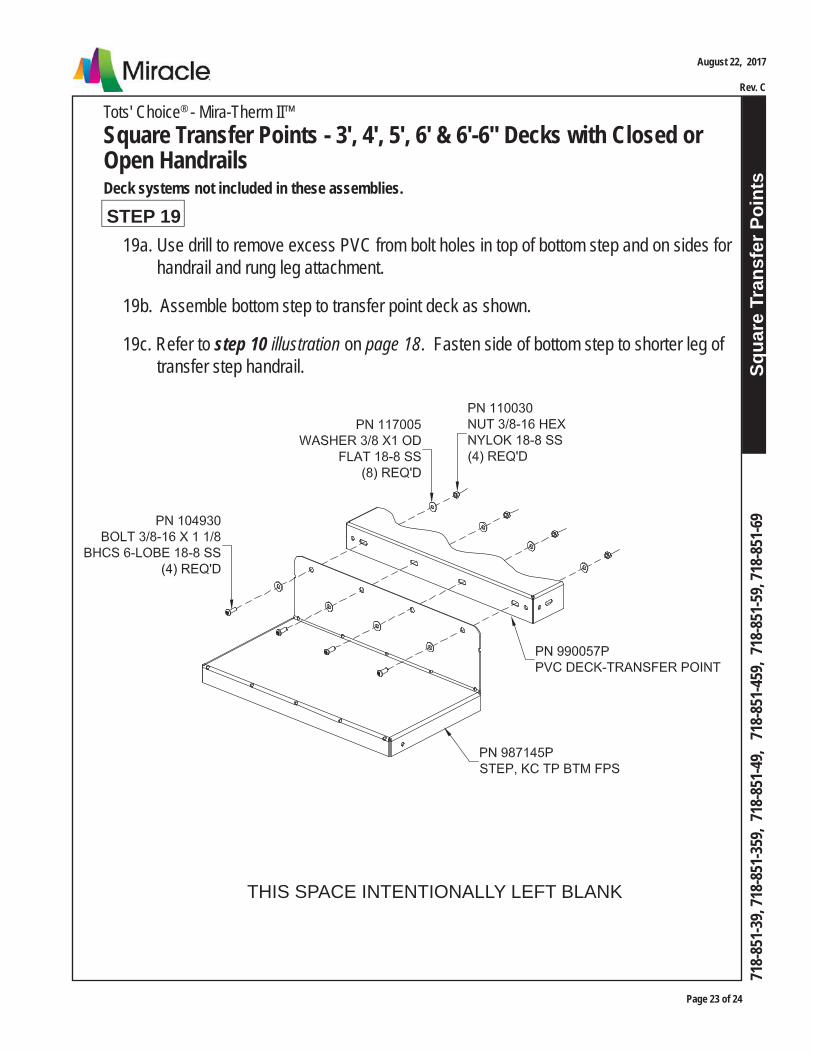
Squa
re T
rans
fer P
oint
s
Page 23 of 24
August 22, 2017
Rev. C
718-
851-
39, 7
18-8
51-3
59, 7
18-8
51-4
9, 7
18-8
51-4
59, 7
18-8
51-5
9, 71
8-85
1-69
Tots' Choice® - Mira-Therm II™Square Transfer Points - 3', 4', 5', 6' & 6'-6" Decks with Closed or Open HandrailsDeck systems not included in these assemblies.
19a. Use drill to remove excess PVC from bolt holes in top of bottom step and on sides for handrail and rung leg attachment.
19b. Assemble bottom step to transfer point deck as shown.
19c. Refer to step 10 illustration on page 18. Fasten side of bottom step to shorter leg of transfer step handrail.
STEP 19
THIS SPACE INTENTIONALLY LEFT BLANK

Page 24 of 24
Squa
re T
rans
fer P
oint
s
Tots' Choice® - Mira-Therm II™Square Transfer Points - 3', 4', 5', 6' & 6'-6" Decks with Closed or Open HandrailsDeck systems not included in these assemblies.
August 22, 2017
Rev. C
718-
851-
39, 7
18-8
51-3
59, 7
18-8
51-4
9, 7
18-8
51-4
59, 7
18-8
51-5
9, 71
8-85
1-69
STEP 20
Plumb and level entire assembly. Tighten all hardware. Proceed with Final Assembly installation.
FINAL STEP
20a. Set rung leg into footing and attach to bottom step as shown.

Leve
l Ram
ps &
Arc
hed
Brid
ges
Tots' Choice®- Mira-Therm II
Level Ramps, 90° Level Ramps and Arched Bridges
Page 1 of 7
718-
856-
9,
718-
856-
59,
718
-856
-L9,
71
8-85
6-L
59,
718
-970
-9,
718
-970
-59
Models included in this installation guide:
MODEL # DESCRIPTION PAGE #
718-856-9 Level Ramp - Spoked Handrails 2718-856-59 Level Ramp - Open Handrails 2718-856-L9 90° Level Ramp - Spoked Handrails 3718-856-L59 90° Level Ramp - Open Handrails 3718-970-9 Arched Bridge - Spoked Handrails 4718-970-59 Arched Bridge - Open Handrails 4
Deck Systems are NOT included in these assemblies.
Please refer to Construction Drawings for the model particular to your system.
IMPORTANT! Prior to installation of any components, refer to Playsystem Installation
Guidelines and Tips in the Install 101 section of your manual. This section will provide importanttips pertaining to site preparation, footings, system stabilization, and other necessaryinformation vital to the success of your installation.
Installation Guide
1. Tape measure and level2. Open end wrench set, Allen and 6-lobe wrenches or bits, socket set, screwdrivers3. Drill, drill bits, extension cords, power supply4. Step ladder5. Bracing materials (2x4s, wood pieces, jack stands, etc.)6. Adult installers - 2 minimum
TOOLS AND EQUIPMENT REQUIREDAlso see 'Suggested Tools & Equipment' (Doc. # D70052) in "Installations 101"
with Spoked & Open Handrails
July 27, 2011
Rev. F
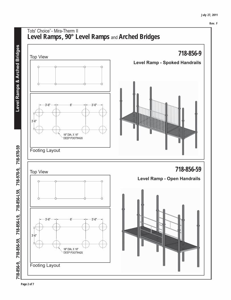
Page 2 of 7
Leve
l Ram
ps &
Arc
hed
Brid
ges
Tots' Choice®- Mira-Therm II
Level Ramps, 90° Level Ramps and Arched Bridges
718-
856-
9,
718-
856-
59,
718
-856
-L9,
71
8-85
6-L
59,
718
-970
-9,
718
-970
-59
Footing Layout
718-856-9Top ViewLevel Ramp - Spoked Handrails
Footing Layout
Top ViewLevel Ramp - Open Handrails
718-856-59
3'-6"
3'-6" 6' 3'-6"
3'-6"
3'-6" 6' 3'-6"
July 27, 2011
Rev. F

Leve
l Ram
ps &
Arc
hed
Brid
ges
Tots' Choice®- Mira-Therm II
Level Ramps, 90° Level Ramps and Arched Bridges
Page 3 of 7
718-
856-
9,
718-
856-
59,
718
-856
-L9,
71
8-85
6-L
59,
718
-970
-9,
718
-970
-59
Footing Layout
Top View90o Level Ramp - Spoked Handrails
Footing Layout
90o Level Ramp - Open HandrailsTop View
718-856-L9
718-856-L59
3'-6" 1'-6" 3'-6"
3'-6"
1'-6"
3'-6"
3'-6" 1'-6" 3'-6"
3'-6"
1'-6"
3'-6"
July 27, 2011
Rev. F
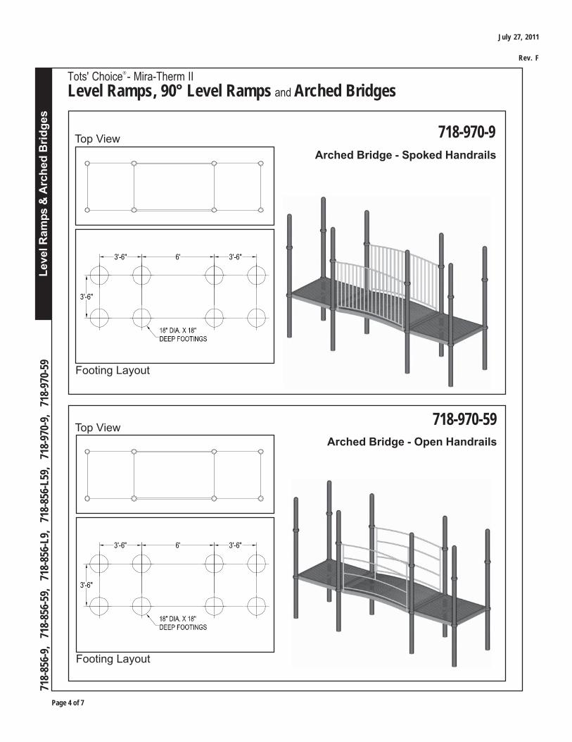
Page 4 of 7
Leve
l Ram
ps &
Arc
hed
Brid
ges
Tots' Choice®- Mira-Therm II
Level Ramps, 90° Level Ramps and Arched Bridges
718-
856-
9,
718-
856-
59,
718
-856
-L9,
71
8-85
6-L
59,
718
-970
-9,
718
-970
-59
Footing Layout
Top ViewArched Bridge - Spoked Handrails
Arched Bridge - Open Handrails
718-970-9
718-970-59
3'-6"
3'-6" 6' 3'-6"
Footing Layout
Top View
3'-6"
3'-6" 6' 3'-6"
July 27, 2011
Rev. F
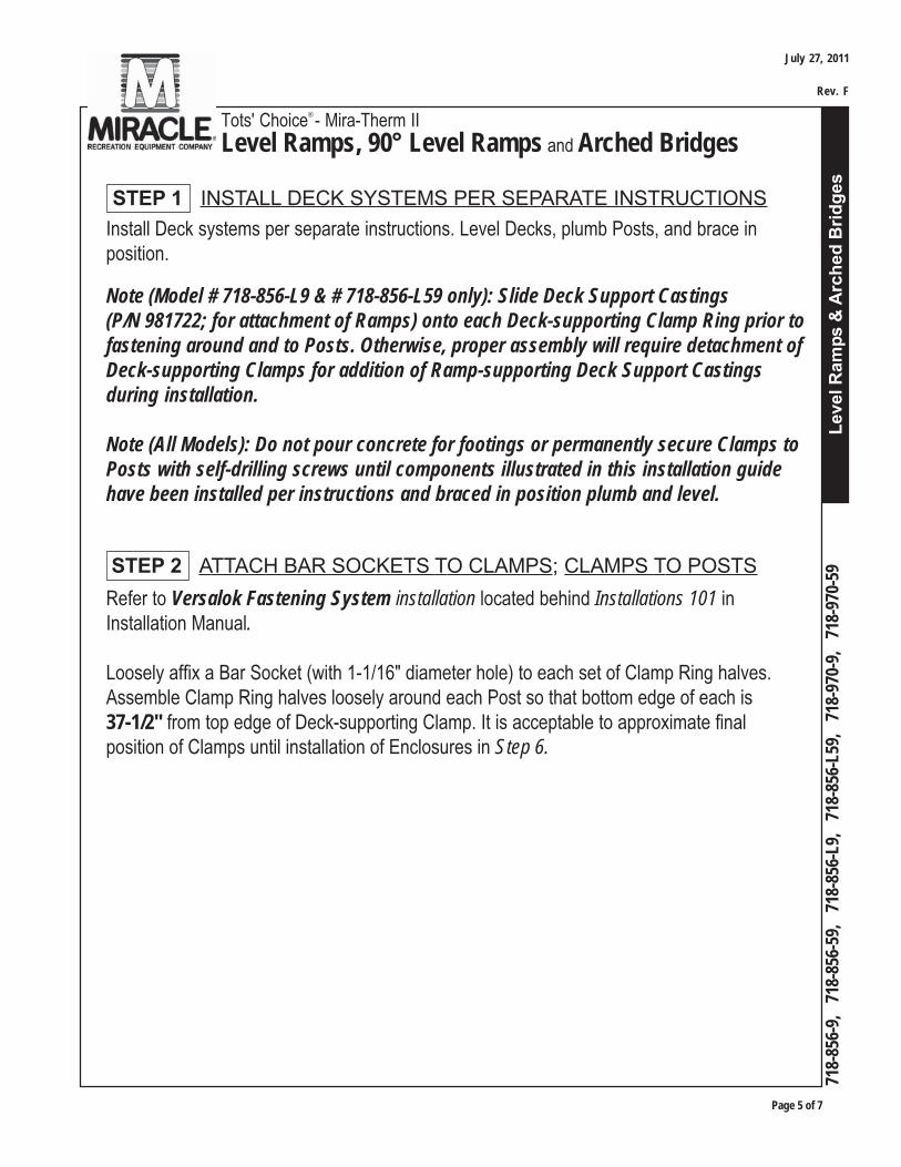
Leve
l Ram
ps &
Arc
hed
Brid
ges
Tots' Choice®- Mira-Therm II
Level Ramps, 90° Level Ramps and Arched Bridges
Page 5 of 7
718-
856-
9,
718-
856-
59,
718
-856
-L9,
71
8-85
6-L
59,
718
-970
-9,
718
-970
-59
Refer to Versalok Fastening System installation located behind Installations 101 inInstallation Manual.
Loosely affix a Bar Socket (with 1-1/16" diameter hole) to each set of Clamp Ring halves.Assemble Clamp Ring halves loosely around each Post so that bottom edge of each is37-1/2" from top edge of Deck-supporting Clamp. It is acceptable to approximate finalposition of Clamps until installation of Enclosures in Step 6.
Install Deck systems per separate instructions. Level Decks, plumb Posts, and brace inposition.
Note (Model # 718-856-L9 & # 718-856-L59 only): Slide Deck Support Castings(P/N 981722; for attachment of Ramps) onto each Deck-supporting Clamp Ring prior tofastening around and to Posts. Otherwise, proper assembly will require detachment ofDeck-supporting Clamps for addition of Ramp-supporting Deck Support Castingsduring installation.
Note (All Models): Do not pour concrete for footings or permanently secure Clamps toPosts with self-drilling screws until components illustrated in this installation guidehave been installed per instructions and braced in position plumb and level.
STEP 2 ATTACH BAR SOCKETS TO CLAMPS; CLAMPS TO POSTS
STEP 1 INSTALL DECK SYSTEMS PER SEPARATE INSTRUCTIONS
July 27, 2011
Rev. F
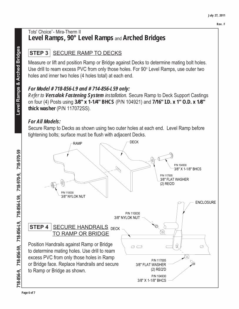
Page 6 of 7
Leve
l Ram
ps &
Arc
hed
Brid
ges
Tots' Choice®- Mira-Therm II
Level Ramps, 90° Level Ramps and Arched Bridges
718-
856-
9,
718-
856-
59,
718
-856
-L9,
71
8-85
6-L
59,
718
-970
-9,
718
-970
-59
P/N 110030
3/8" NYLOK NUT
P/N 117005
3/8" FLAT WASHER(2) REQ'D
P/N 104930
3/8" X 1-1/8" BHCS
ENCLOSURE
DECK
RAMP DECK
P/N 110030
3/8" NYLOK NUT
P/N 104930
3/8" X 1-1/8" BHCS
P/N 117005
3/8" FLAT WASHER(2) REQ'D
STEP 3 SECURE RAMP TO DECKS
Position Handrails against Ramp or Bridgeto determine mating holes. Use drill to reamexcess PVC from only those holes in Rampor Bridge face. Replace Handrails and secureto Ramp or Bridge as shown.
STEP 4 SECURE HANDRAILS TO RAMP OR BRIDGE
Measure or lift and position Ramp or Bridge against Decks to determine mating bolt holes.Use drill to ream excess PVC from only those holes. For 90o Level Ramps, use outer twoholes and inner two holes (4 holes total) at each end.
For Model # 718-856-L9 and # 714-856-L59 only:Refer to Versalok Fastening System installation. Secure Ramp to Deck Support Castingson four (4) Posts using 3/8" x 1-1/4" BHCS (P/N 104921) and 7/16" I.D. x 1" O.D. x 1/8"thick washer (P/N 117072SS).
For All Models:Secure Ramp to Decks as shown using two outer holes at each end. Level Ramp beforetightening bolts; surface must be flush with adjacent Decks.
July 27, 2011
Rev. F
Leve
l Ram
ps &
Arc
hed
Brid
ges
Tots' Choice®- Mira-Therm II
Level Ramps, 90° Level Ramps and Arched Bridges
Page 7 of 7
718-
856-
9,
718-
856-
59,
718
-856
-L9,
71
8-85
6-L
59,
718
-970
-9,
718
-970
-59
Refer to Versalok Fastening System installation located behind Installations 101 in InstallationManual. Repositioning Clamps as needed, insert ends of Enclosures' top rails into Bar Sockets.Tighten Enclosures in Bar Sockets, Bar Sockets on Clamps, and Clamp Rings around Posts.
STEP 5 ATTACH ENCLOSURES
Proceed with Final Assembly installation located behind Installations 101 in InstallationManual.
FINAL STEP
July 27, 2011
Rev. F

Tots' Choice®
Curved Loop Climbers from 5' & 6' and 3' & 4' Decks
Cur
ved
Loop
Clim
bers
Page 1 of 5
Installation Guide
718-
943,
71
8-96
8
Deck system not included in these assemblies.
Footing Layout
718-943 installed on 5' Deck
Top ViewCurved Loop Climber from 5' or 6' Deck
Footing Layout
Top ViewCurved Loop Climber from 5' or 6' Deck
718-968
718-968
718-943 installed on 6' Deck
7'-7"
1'
1'-6"
18" DIA X 18"DEEP FOOTING
12" DIA X 18"DEEP FOOTING
3'-6"
3'-6"
8'-2"
1'
1'-6"
18" DIA X 18"DEEP FOOTING
12" DIA X 18"DEEP FOOTING
3'-6"
3'-6"
February 11, 2004
Rev. E
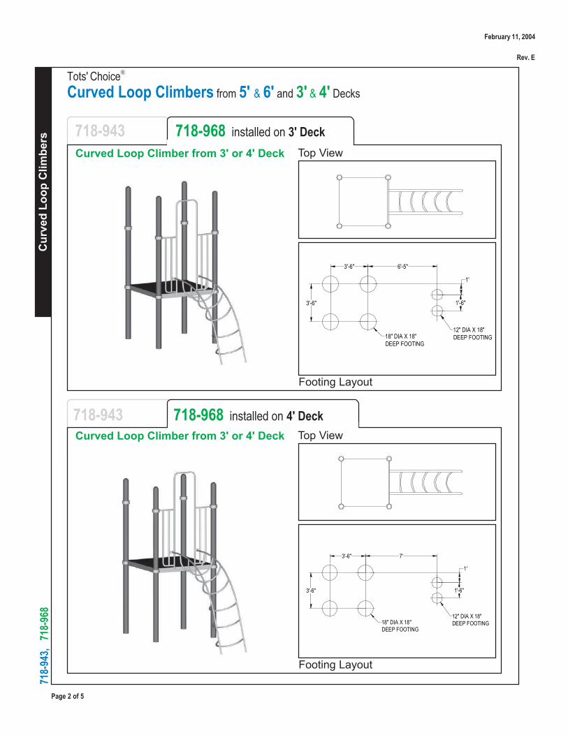
Page 2 of 5
Cur
ved
Loop
Clim
bers
Tots' ChoiceCurved Loop Climbers from 5' & 6' and 3' & 4' Decks
718-
943,
71
8-96
8
Footing Layout
718-943 718-968 installed on 3' Deck
Curved Loop Climber from 3' or 4' Deck
Footing Layout
Curved Loop Climber from 3' or 4' Deck
Top View
Top View718-943 718-968 installed on 4' Deck
1'-6"
1'
6'-5"
18" DIA X 18"DEEP FOOTING
12" DIA X 18"DEEP FOOTING
3'-6"
3'-6"
7'
18" DIA X 18"DEEP FOOTING
12" DIA X 18"DEEP FOOTING
3'-6"
3'-6" 1'-6"
1'
®
February 11, 2004
Rev. E

Cur
ved
Loop
Clim
bers
Tots' Choice®
Curved Loop Climbers from 5' & 6' and 3' & 4' Decks
Page 3 of 5
718-
943,
71
8-96
8
PARTS IDENTIFICATION
RECOMMENDED ASSEMBLY SEQUENCE1. Deck system (per separate instructions)2. Footings3. Bar Sockets loosely to Clamps; Clamps loosely to Posts4. Enclosure to Posts and to Deck5. Climber side rails into Footings; Climber to Enclosure6. Final Assembly
1. Concrete for Footings, wheelbarrow or mixer, 5 gallon bucket, water supply2. Digging equipment for Footings (spade shovel, post hole digger, auger)3. Tape measure and level4. Open end wrench set, Allen and 6-lobe wrenches or bits, socket set, screwdrivers5. Drill, drill bits, extension cords, power supply6. Saw or grinder (to adjust length of Climber side rails, if needed)7. Step ladder8. Adult installers - 2 minimum
TOOLS AND EQUIPMENT REQUIREDAlso see 'Suggested Tools & Equipment' (Doc. # D70052) in "Installations 101"
Model # 718-943
CURVED LOOP CLIMBER
ARCHED ENCLOSURE
VERSALOK CLAMP & BAR SOCKET(2) EA REQ'DDECK POST
DECK
February 11, 2004
Rev. E

Page 4 of 5
Cur
ved
Loop
Clim
bers
Tots' ChoiceCurved Loop Climbers from 5' & 6' and 3' & 4' Decks
718-
943,
71
8-96
8
Dig Footings per Footing Layout or Construction Drawings. Refer to Footing Detailsinstallation.
Note: Do not pour concrete for Footings or permanently secure Clamps to Postswith self-drilling screws, until all components in system have been installed perinstructions and braced in position level and plumb.
Read Safety Brochure 100, Important Notes, these instructions, and other enclosedmaterials. Unpack, count, and become familiar with system components and hardware.
STEP 3
STEP 1
Install Deck system per separate instructions. Plumb, level, and brace in position.
STEP 2
STEP 4
Refer to Versalok Fastening System installation.
Slide a Bar Socket (with 1-1/16" diameter hole; P/N 981721) onto each set of Clamp Ringhalves. Loosely assemble Clamp Rings around Posts so that bottom edge of each Clamp is37-1/2" from top edge of Deck-supporting Clamp.
Position Enclosure against Deck to locate mating bolt holes. Use drill to ream excess PVCfrom only those holes in Deck.
Assemble Enclosure top rails in Bar Sockets on Clamps.
Note: Welded brackets on Enclosure must be located outside (away from Deck.)
®
February 11, 2004
Rev. E
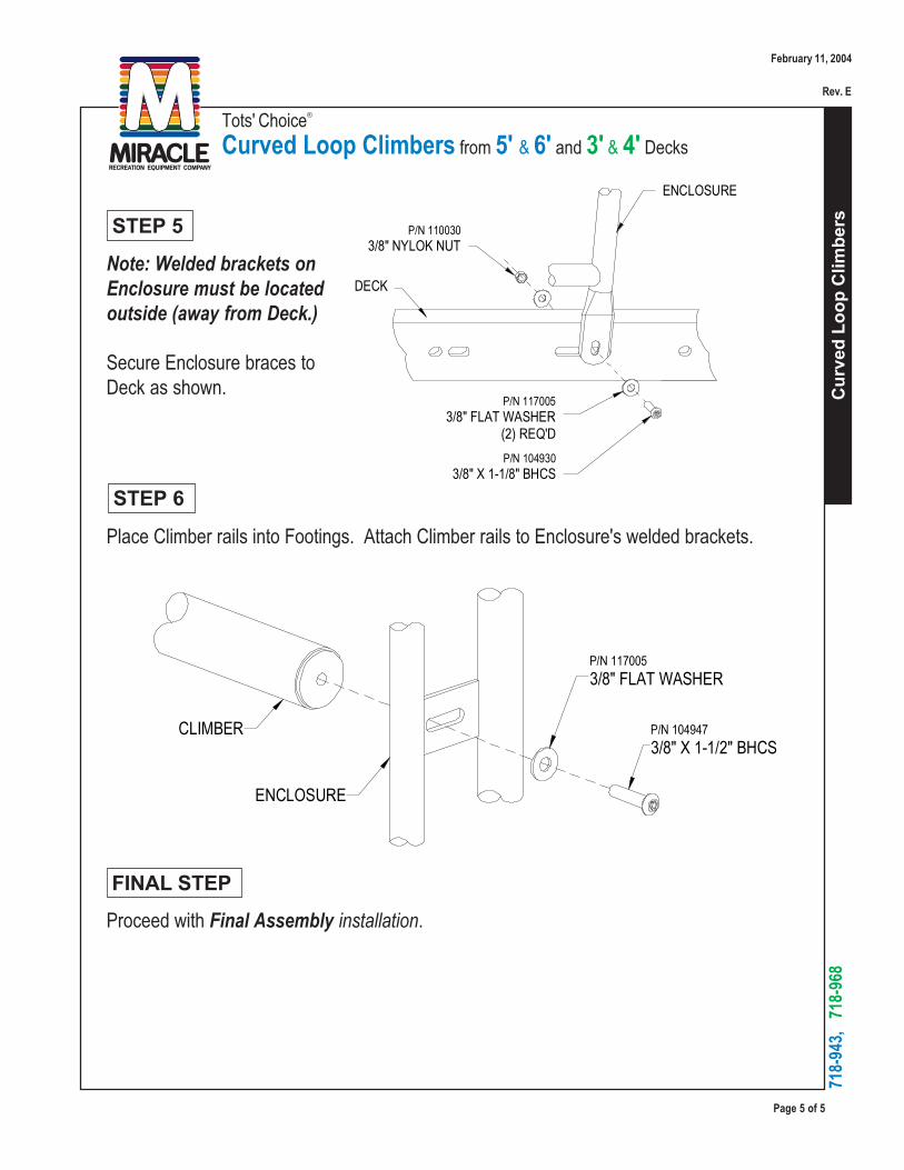
Cur
ved
Loop
Clim
bers
Tots' Choice®
Curved Loop Climbers from 5' & 6' and 3' & 4' Decks
Page 5 of 5
718-
943,
71
8-96
8
Place Climber rails into Footings. Attach Climber rails to Enclosure's welded brackets.
STEP 6
Secure Enclosure braces toDeck as shown.
STEP 5
Proceed with Final Assembly installation.
FINAL STEP
Note: Welded brackets onEnclosure must be locatedoutside (away from Deck.)
P/N 1100303/8" NYLOK NUT
P/N 1170053/8" FLAT WASHER
(2) REQ'D
P/N 1049303/8" X 1-1/8" BHCS
ENCLOSURE
DECK
CLIMBER
ENCLOSURE
P/N 117005
3/8" FLAT WASHER
P/N 104947
3/8" X 1-1/2" BHCS
February 11, 2004
Rev. E

Del
ight
-O-S
cope
Tel
esco
pe &
Bin
ocul
ars
Tots' Choice®
Delight-O-Scope Telescope & Binoculars
Page 1 of 8
718-
961-
1,
718-
961-
P1,
71
8-96
1-2,
71
8-96
1-P
2
Installation Guide
Footing Layout
718-961-1 718-961-P1 718-961-2 718-961-P2Top ViewDelight-O-Scope Telescope, Freestanding
Footing Layout
718-961-1 718-961-P1 718-961-2 718-961-P2Top View
Freestanding & Deck Post Mounting
Footing Layout not shown. Model mounts atop a DeckPost.
18" DIA. X 18"DEEP FOOTING
Delight-O-Scope Telescope, Deck PostMounting
May 27, 2004
Rev. A
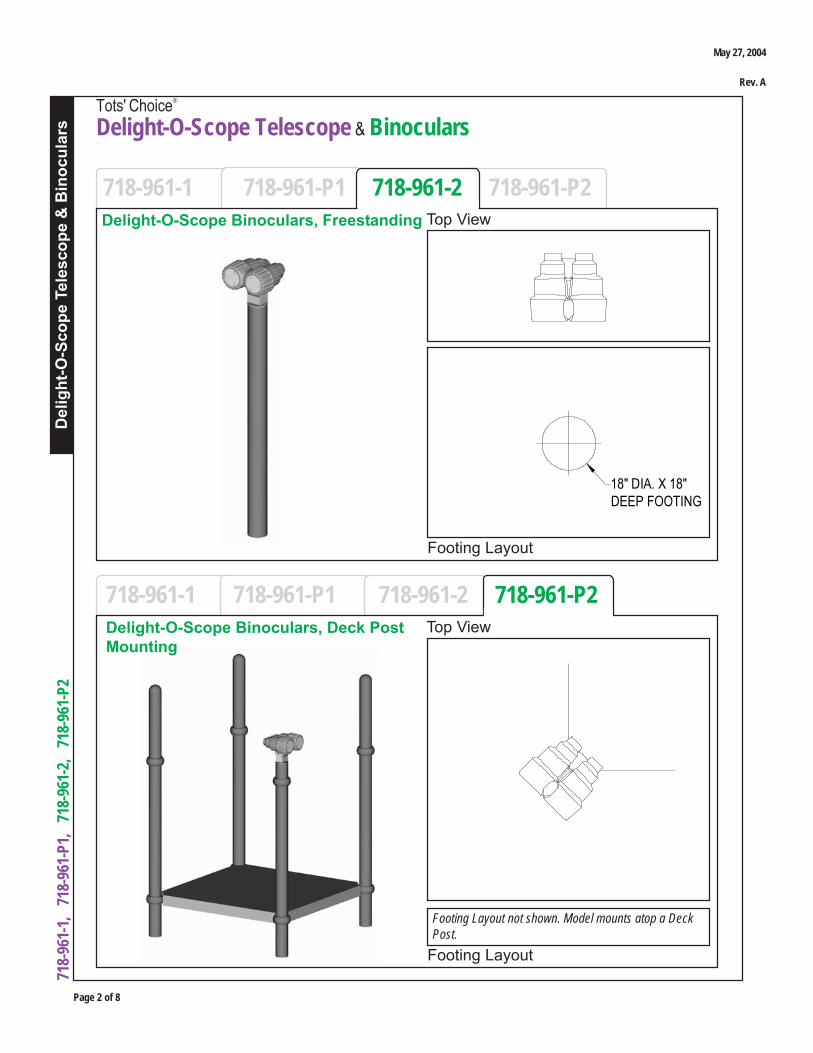
Page 2 of 8
Del
ight
-O-S
cope
Tel
esco
pe &
Bin
ocul
ars
Tots' Choice®
Delight-O-Scope Telescope & Binoculars
718-
961-
1,
718-
961-
P1,
71
8-96
1-2,
71
8-96
1-P
2
Footing Layout
718-961-1 718-961-P1 718-961-2 718-961-P2Top ViewDelight-O-Scope Binoculars, Freestanding
Footing Layout
718-961-1 718-961-P1 718-961-2 718-961-P2Top View
Footing Layout not shown. Model mounts atop a DeckPost.
18" DIA. X 18"DEEP FOOTING
Delight-O-Scope Binoculars, Deck PostMounting
May 27, 2004
Rev. A

Del
ight
-O-S
cope
Tel
esco
pe &
Bin
ocul
ars
Tots' Choice®
Delight-O-Scope Telescope & Binoculars
Page 3 of 8
718-
961-
1,
718-
961-
P1,
71
8-96
1-2,
71
8-96
1-P
2
1. Remove Post end cap and cut Post, if necessary2. Deck system (per separate instructions)3. Delight-O-Scope model in Post end4. Remaining components to Deck system5. Final Assembly
Deck Post Mounting Models (New Installation)
1. Remove Post end cap or cut Post, if necessary2. Remove self-drilling screws from existing Clamp3. Delight-O-Scope model in Post end4. Replace screws through Clamp, Post and Delight-O-Scope5. Final Assembly
Deck Post Mounting Models (Retrofit)
1. Concrete for Footings, wheelbarrow or mixer, 5 gallon bucket, water supply2. Digging equipment for Footings (spade shovel, post hole digger, auger)3. Bracing materials (2x4s, wood pieces, concrete blocks, bricks, jack stands, sawhorses, etc.)4. Tape measure and level5. Open end wrench set, Allen and 6-lobe wrenches or bits, socket set, screwdrivers6. Drill, bits, extension cords, power supply7. Rubber mallet8. Hammer with cold chisel or large screwdriver (or drill) for Post end cap removal9. Saw and grinder for cutting and smoothing (if Post height adjustment is necessary)10. Adult installer
TOOLS AND EQUIPMENT REQUIREDAlso see 'Suggested Tools & Equipment' (Doc. # D70052) in "Installations 101"
1. Footing2. Delight-O-Scope model in Post end3. Assembly into Footing4. Final Assembly
RECOMMENDED ASSEMBLY SEQUENCEFreestanding Models
Instructions p. 4
Instructions p. 5
Instructions p. 7
May 27, 2004
Rev. A
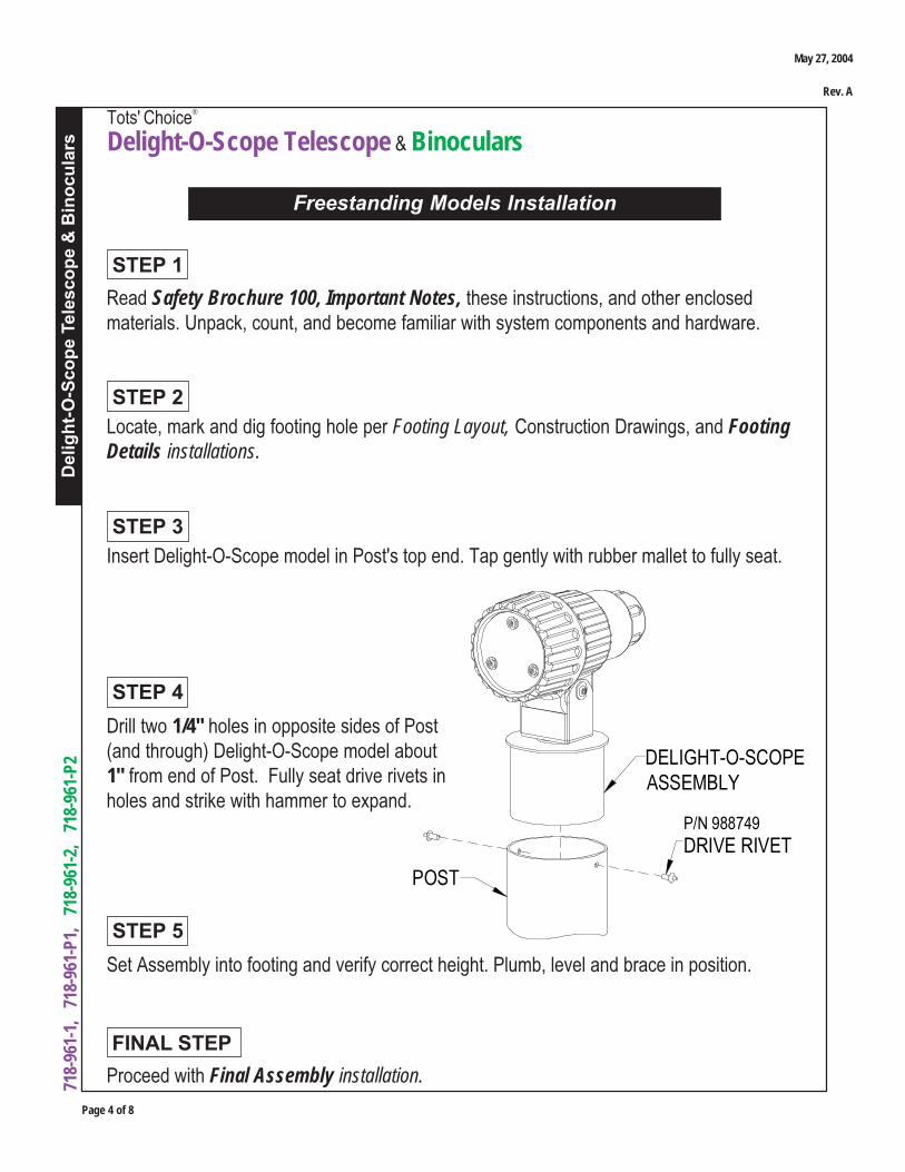
Page 4 of 8
Del
ight
-O-S
cope
Tel
esco
pe &
Bin
ocul
ars
Tots' Choice®
Delight-O-Scope Telescope & Binoculars
718-
961-
1,
718-
961-
P1,
71
8-96
1-2,
71
8-96
1-P
2 DELIGHT-O-SCOPEASSEMBLY
POST
P/N 988749
DRIVE RIVET
Drill two 1/4" holes in opposite sides of Post(and through) Delight-O-Scope model about1" from end of Post. Fully seat drive rivets inholes and strike with hammer to expand.
STEP 4
Locate, mark and dig footing hole per Footing Layout, Construction Drawings, and FootingDetails installations.
Insert Delight-O-Scope model in Post's top end. Tap gently with rubber mallet to fully seat.
Read Safety Brochure 100, Important Notes, these instructions, and other enclosedmaterials. Unpack, count, and become familiar with system components and hardware.
STEP 3
STEP 2
STEP 1
Proceed with Final Assembly installation.
FINAL STEP
Freestanding Models Installation
Set Assembly into footing and verify correct height. Plumb, level and brace in position.
STEP 5
May 27, 2004
Rev. A
Del
ight
-O-S
cope
Tel
esco
pe &
Bin
ocul
ars
Tots' Choice®
Delight-O-Scope Telescope & Binoculars
Page 5 of 8
718-
961-
1,
718-
961-
P1,
71
8-96
1-2,
71
8-96
1-P
2
Read Safety Brochure 100, Important Notes, these instructions, and other enclosedmaterials. Unpack, count, and become familiar with system components and hardware.
STEP 1
Deck Post Mounting Models (New Installation)
Select Deck Post to receive Delight-O-Scope model, as specified in Construction Drawing.Use hammer and cold chisel (or large screw driver, and drill if necessary) to remove roundedend cap from top of Post.
STEP 2
STEP 3Ideal Post length for Delight-O-Scope assembly is the sum of the intended Deck height plus70½" (e.g. 94½" for a 2' Deck), though a variance of ½" is acceptable. If Post length is such,skip to Step 4. Otherwise, length adjustment is recommended per options below.
Option #1 (Adjust Post length before installing with Deck)Measure Post from bottom to find proper location for cut. Mark Post at intended Deck heightplus 70½". (The 70½" includes an 18" length of Post beneath sub-grade, 12" protectivesurfacing, typical (approximate) enclosure mounting height of 39" from Deck to Clamp top, and1½" between Clamp top and Post top without end cap.) Cut Post at mark and grind smooth,then install Post with Deck system per separate instructions.
Option #2 (Adjust Post length after installing with Deck)Install Deck system per separate instructions. Plumb, level and brace in position.
Refer to Versalok Fastening System installation. Set Clamp height on Post per componentinstructions and positioning of components. Assemble Clamp Ring halves together aroundPost at proper location, without installing self-drilling screws in Post. Mark Post at 1" to 2"(maximum) from top of Clamp. Cut Post at mark and grind smooth.
Note: Some components are designed to mount at higher than standard location on Posts.Therefore, it is important to reference each Post-sharing component's Installation Guide andposition components to determine proper Clamp heights prior to cutting Post!
May 27, 2004
Rev. A
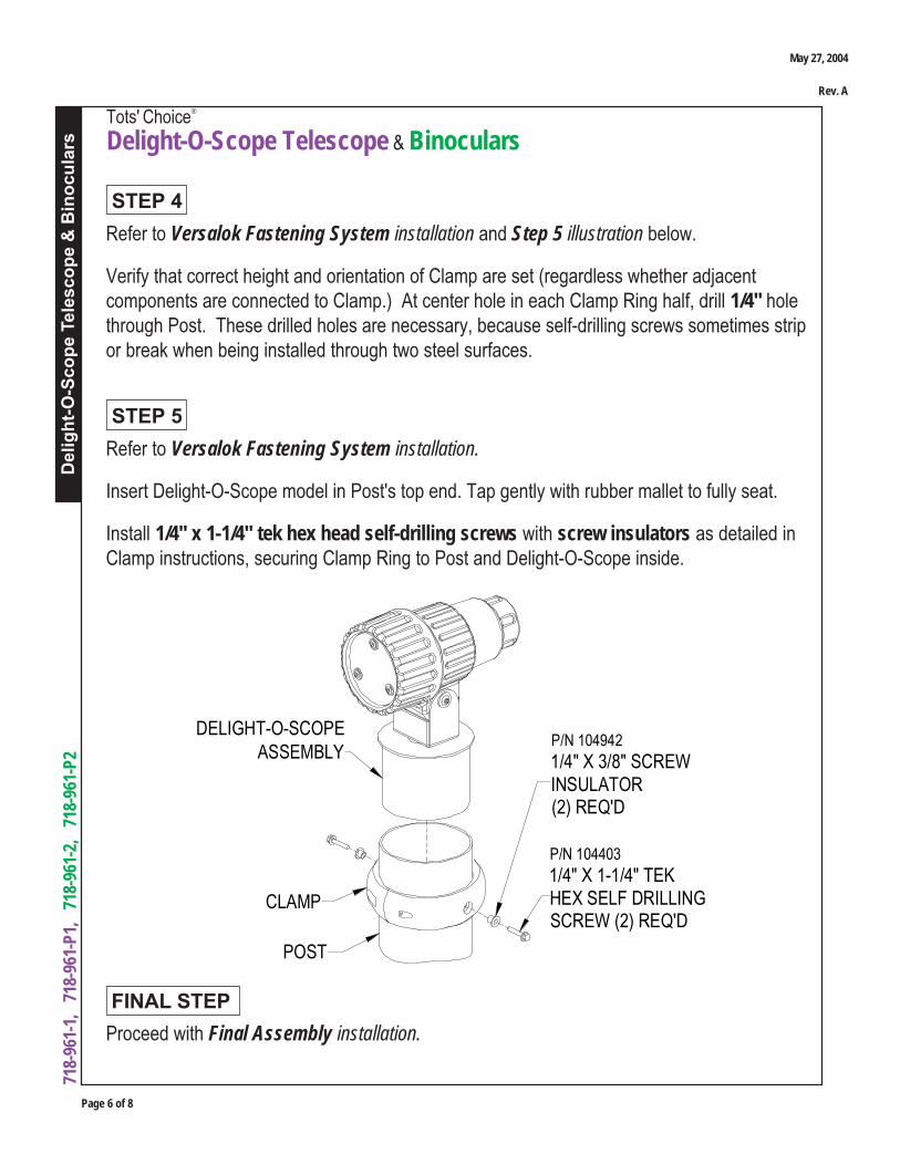
Page 6 of 8
Del
ight
-O-S
cope
Tel
esco
pe &
Bin
ocul
ars
Tots' Choice®
Delight-O-Scope Telescope & Binoculars
718-
961-
1,
718-
961-
P1,
71
8-96
1-2,
71
8-96
1-P
2
Refer to Versalok Fastening System installation and Step 5 illustration below.
Verify that correct height and orientation of Clamp are set (regardless whether adjacentcomponents are connected to Clamp.) At center hole in each Clamp Ring half, drill 1/4" holethrough Post. These drilled holes are necessary, because self-drilling screws sometimes stripor break when being installed through two steel surfaces.
STEP 4
Refer to Versalok Fastening System installation.
Insert Delight-O-Scope model in Post's top end. Tap gently with rubber mallet to fully seat.
Install 1/4" x 1-1/4" tek hex head self-drilling screws with screw insulators as detailed inClamp instructions, securing Clamp Ring to Post and Delight-O-Scope inside.
STEP 5
Proceed with Final Assembly installation.
FINAL STEP
P/N 104403
1/4" X 1-1/4" TEKHEX SELF DRILLINGSCREW (2) REQ'D
P/N 104942
1/4" X 3/8" SCREWINSULATOR(2) REQ'D
CLAMP
POST
DELIGHT-O-SCOPEASSEMBLY
May 27, 2004
Rev. A

Del
ight
-O-S
cope
Tel
esco
pe &
Bin
ocul
ars
Tots' Choice®
Delight-O-Scope Telescope & Binoculars
Page 7 of 8
718-
961-
1,
718-
961-
P1,
71
8-96
1-2,
71
8-96
1-P
2
CLAMP
POST
2" MAX.
TOP OF POSTTO BE CUT OFF
3-3/4"2" MAX.
CLAMP
DELIGHT-O-SCOPEASSEMBLY
Deck Post Mounting Models (Retrofit)
Read Safety Brochure 100, Important Notes, these instructions, and other enclosedmaterials. Unpack, count, and become familiar with system components and hardware.
STEP 1
Measure distance between top edge of highestClamp and end of Post, before end cap.
If distance is 2" or less, proceed to Step 3.
If distance is greater than 2", skip to Step 4.
Note: If installing atop Post at height greater than 3-3/4" from Clamp top, follow instructionsfor Freestanding Models installation on Page 4.
STEP 2
Remove rounded end cap from top of target Post by drilling out rivets (if present) or tappingaround bottom edge with cold chisel and hammer (or large screwdriver.) Skip to Step 5 onnext page.
STEP 3
Mark and cut Post at 2" or less fromtop edge of highest Clamp. Proceed toStep 5.
STEP 4
May 27, 2004
Rev. A
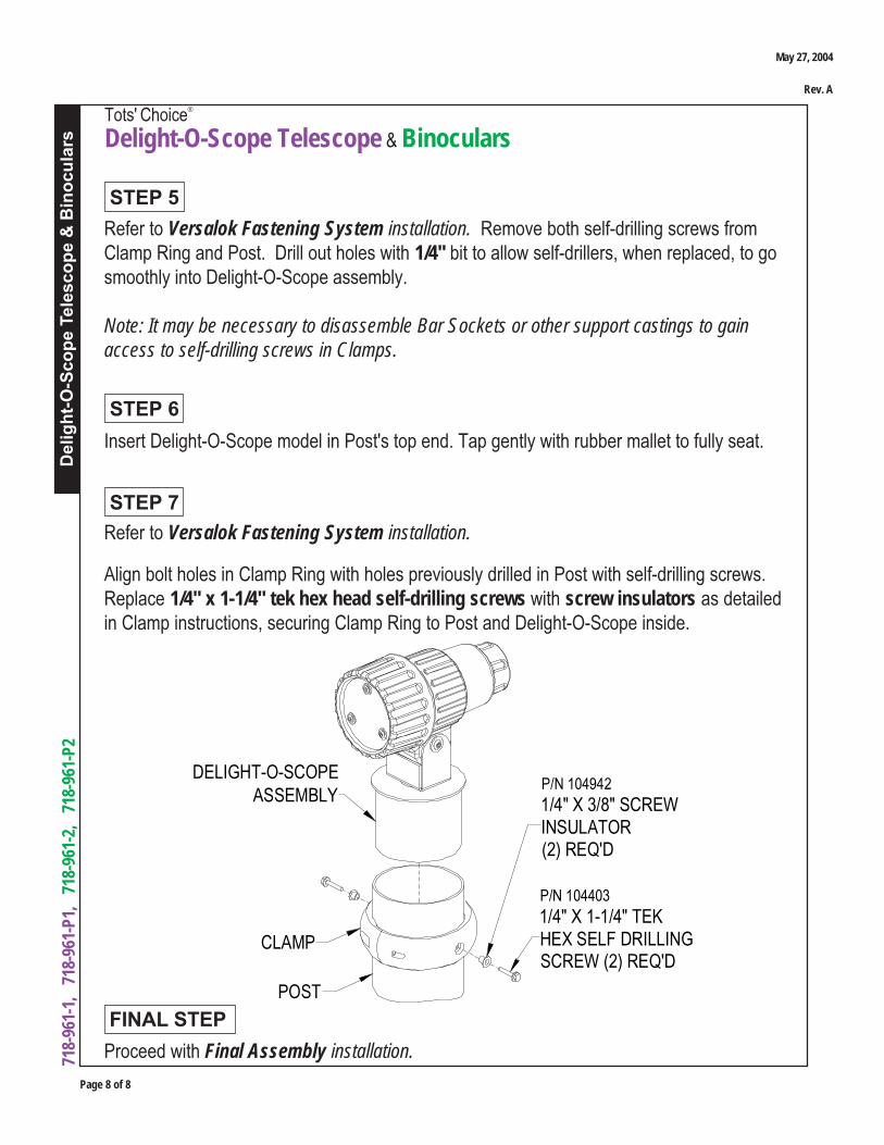
Page 8 of 8
Del
ight
-O-S
cope
Tel
esco
pe &
Bin
ocul
ars
Tots' Choice®
Delight-O-Scope Telescope & Binoculars
718-
961-
1,
718-
961-
P1,
71
8-96
1-2,
71
8-96
1-P
2
P/N 104403
1/4" X 1-1/4" TEKHEX SELF DRILLINGSCREW (2) REQ'D
P/N 104942
1/4" X 3/8" SCREWINSULATOR(2) REQ'D
CLAMP
POST
DELIGHT-O-SCOPEASSEMBLY
Proceed with Final Assembly installation.
FINAL STEP
Refer to Versalok Fastening System installation. Remove both self-drilling screws fromClamp Ring and Post. Drill out holes with 1/4" bit to allow self-drillers, when replaced, to gosmoothly into Delight-O-Scope assembly.
Note: It may be necessary to disassemble Bar Sockets or other support castings to gainaccess to self-drilling screws in Clamps.
STEP 5
Insert Delight-O-Scope model in Post's top end. Tap gently with rubber mallet to fully seat.
STEP 6
Refer to Versalok Fastening System installation.
Align bolt holes in Clamp Ring with holes previously drilled in Post with self-drilling screws.Replace 1/4" x 1-1/4" tek hex head self-drilling screws with screw insulators as detailedin Clamp instructions, securing Clamp Ring to Post and Delight-O-Scope inside.
STEP 7
May 27, 2004
Rev. A

Car
go C
limbe
rs
Tots' Choice®
Cargo Climbers
Page 1 of 8
718-
995,
7
18-9
95-1
, 7
18-9
96,
718
-996
-1,
718
-997
, 7
18-9
97-1
Footing Layout
Installation GuideDeck systems not included in these assemblies.
718-995 718-995-1 718-996 718-996-1 718-997 718-997-1
Footing Layout
Top View
Cargo Climber for 5' Deck Top View
Cargo Climber with Handholdfor 5' Deck
718-995 718-995-1 718-996 718-996-1 718-997 718-997-1
for 5', 3' and 4' Decks, with and without Handholds
April 15, 2005
Rev. K

Page 2 of 8
Car
go C
limbe
rs
Tots' Choice®
Cargo Climbers
718-
995,
7
18-9
95-1
, 7
18-9
96,
718
-996
-1,
718
-997
, 7
18-9
97-1
718-995 718-995-1 718-996 718-996-1 718-997 718-997-1
718-995 718-995-1 718-996 718-996-1 718-997 718-997-1
Footing Layout
Cargo Climber for 3' Deck
Footing Layout
Top View
Cargo Climber with Handholdfor 3' Deck
Top View
April 15, 2005
Rev. K
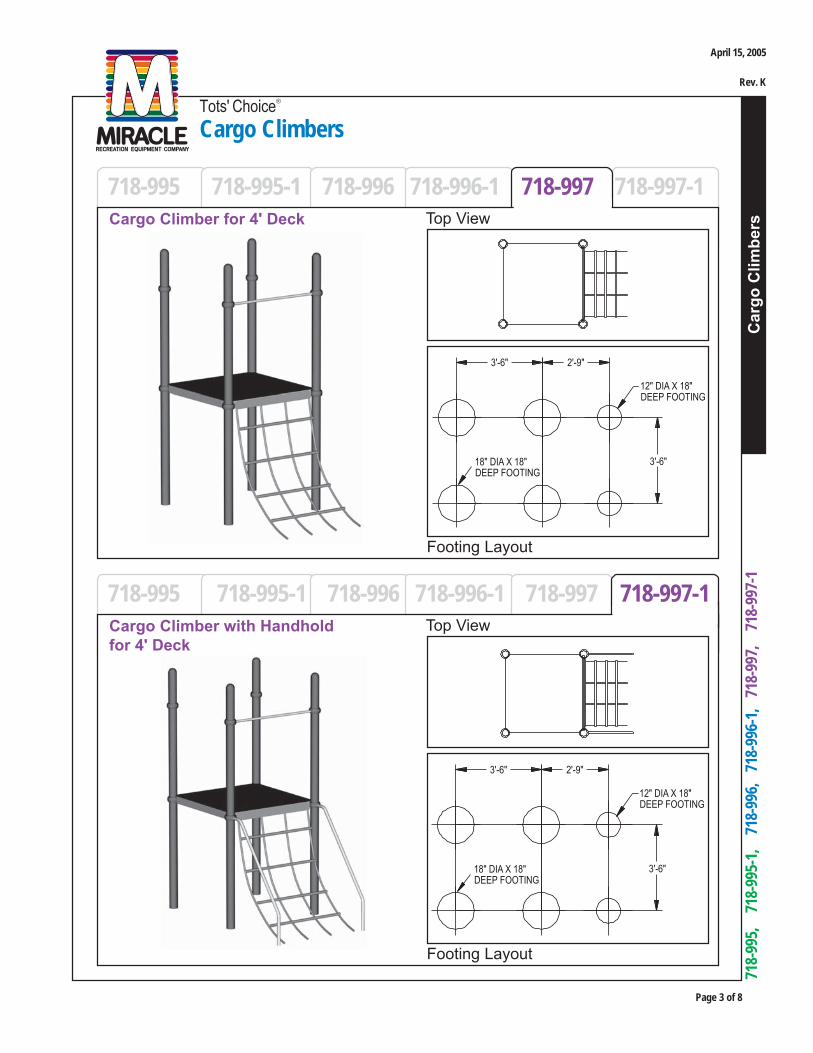
Car
go C
limbe
rs
Tots' Choice®
Cargo Climbers
Page 3 of 8
718-
995,
7
18-9
95-1
, 7
18-9
96,
718
-996
-1,
718
-997
, 7
18-9
97-1
718-995 718-995-1 718-996 718-996-1 718-997 718-997-1
718-995 718-995-1 718-996 718-996-1 718-997 718-997-1
Footing Layout
Cargo Climber for 4' Deck
Footing Layout
Top View
Top ViewCargo Climber with Handholdfor 4' Deck
April 15, 2005
Rev. K
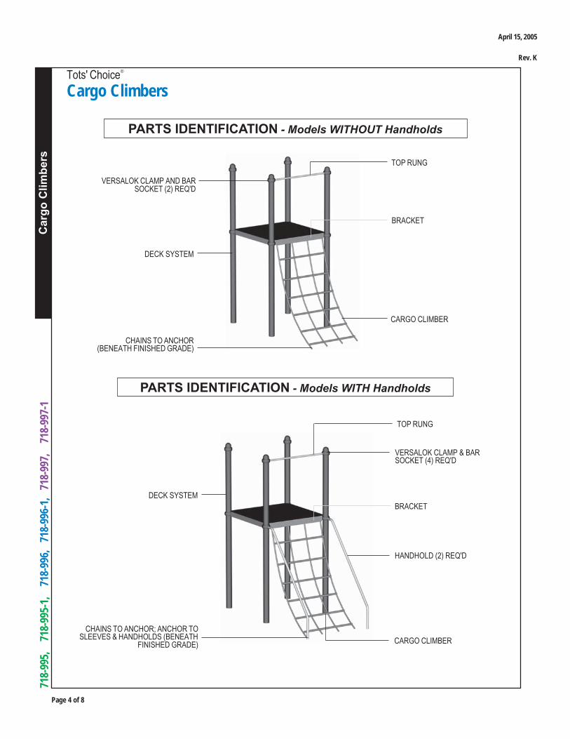
Page 4 of 8
Car
go C
limbe
rs
Tots' Choice®
Cargo Climbers
718-
995,
7
18-9
95-1
, 7
18-9
96,
718
-996
-1,
718
-997
, 7
18-9
97-1
TOP RUNG
PARTS IDENTIFICATION - Models WITHOUT Handholds
CHAINS TO ANCHOR(BENEATH FINISHED GRADE)
CARGO CLIMBER
VERSALOK CLAMP AND BARSOCKET (2) REQ'D
DECK SYSTEM
TOP RUNG
PARTS IDENTIFICATION - Models WITH Handholds
CHAINS TO ANCHOR; ANCHOR TOSLEEVES & HANDHOLDS (BENEATH
FINISHED GRADE)
VERSALOK CLAMP & BARSOCKET (4) REQ'D
HANDHOLD (2) REQ'D
CARGO CLIMBER
DECK SYSTEM
BRACKET
BRACKET
April 15, 2005
Rev. K

Car
go C
limbe
rs
Tots' Choice®
Cargo Climbers
Page 5 of 8
718-
995,
7
18-9
95-1
, 7
18-9
96,
718
-996
-1,
718
-997
, 7
18-9
97-1
RECOMMENDED ASSEMBLY SEQUENCE1. Deck system (per separate instructions)2. Footings3. Bar Sockets and Clamps loosely to Deck Posts4. Top Rung to Posts (via Clamps)5. Cargo Climber Bracket to Deck6. Cargo Climber Chains to Anchor; close S-hooks7. For Model # 718-995-1, # 718-996-1, or # 718-997-1 (Models WITH Handholds) only: Handholds into footings, to Posts (via Clamps)8. For Model # 718-995-1, # 718-996-1, or # 718-997-1 (Models WITH Handholds) only: Handholds and Sleeves to Anchor9. For Model # 718-995, # 718-996, or # 718-997 (Models WITHOUT Handholds) only: Anchor into footings; block or stake for tension10. Final Assembly
1. Concrete for footings, wheelbarrow or mixer, 5 gallon bucket, water supply2. Digging equipment for footings (spade shovel, post hole digger, auger)3. Bracing materials (2x4s, wood pieces, jack stands, sawhorses, concrete blocks, bricks, etc.)4. Tape measure and level5. Open end wrench set, Allen and 6-lobe wrenches or bits, socket set, screwdrivers6. Drill, 5/16" drill bit or larger, extension cords, power supply7. S-hook pliers8. Adult installers - 2 minimum
TOOLS AND EQUIPMENT REQUIREDAlso see 'Suggested Tools & Equipment' (Doc. # D70052) in "Installations 101"
April 15, 2005
Rev. K
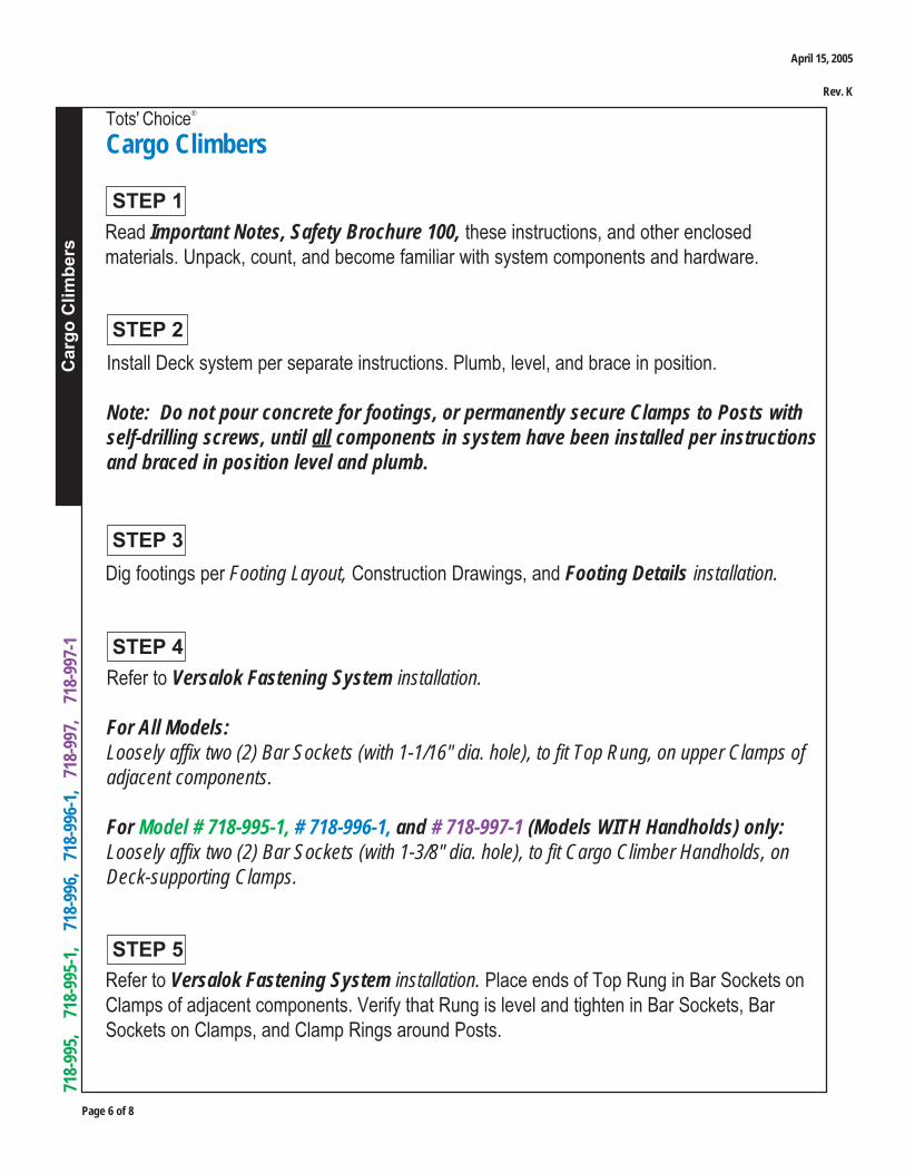
Page 6 of 8
Car
go C
limbe
rs
Tots' Choice®
Cargo Climbers
718-
995,
7
18-9
95-1
, 7
18-9
96,
718
-996
-1,
718
-997
, 7
18-9
97-1
Read Important Notes, Safety Brochure 100, these instructions, and other enclosedmaterials. Unpack, count, and become familiar with system components and hardware.
STEP 3
STEP 2
STEP 1
Install Deck system per separate instructions. Plumb, level, and brace in position.
Note: Do not pour concrete for footings, or permanently secure Clamps to Posts withself-drilling screws, until all components in system have been installed per instructionsand braced in position level and plumb.
Dig footings per Footing Layout, Construction Drawings, and Footing Details installation.
Refer to Versalok Fastening System installation. Place ends of Top Rung in Bar Sockets onClamps of adjacent components. Verify that Rung is level and tighten in Bar Sockets, BarSockets on Clamps, and Clamp Rings around Posts.
STEP 5
Refer to Versalok Fastening System installation.
For All Models:Loosely affix two (2) Bar Sockets (with 1-1/16" dia. hole), to fit Top Rung, on upper Clamps ofadjacent components.
For Model # 718-995-1, # 718-996-1, and # 718-997-1 (Models WITH Handholds) only:Loosely affix two (2) Bar Sockets (with 1-3/8" dia. hole), to fit Cargo Climber Handholds, onDeck-supporting Clamps.
STEP 4
April 15, 2005
Rev. K
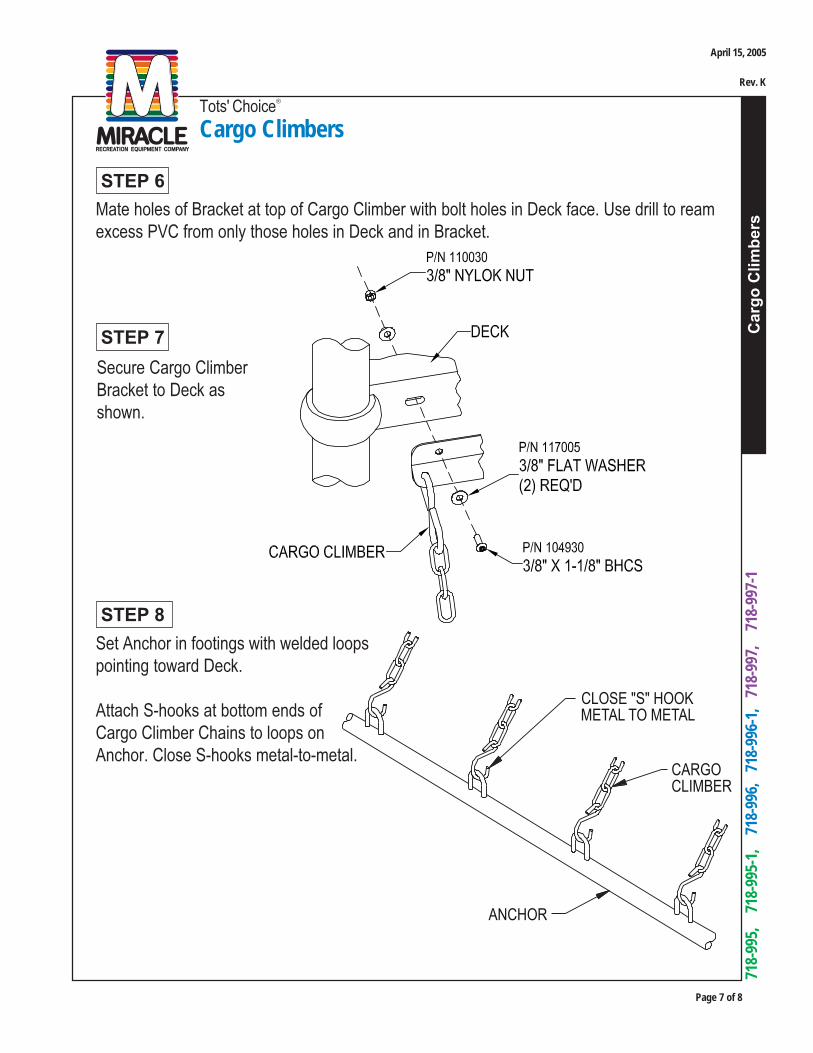
Car
go C
limbe
rs
Tots' Choice®
Cargo Climbers
Page 7 of 8
718-
995,
7
18-9
95-1
, 7
18-9
96,
718
-996
-1,
718
-997
, 7
18-9
97-1
Mate holes of Bracket at top of Cargo Climber with bolt holes in Deck face. Use drill to reamexcess PVC from only those holes in Deck and in Bracket.
STEP 6
Secure Cargo ClimberBracket to Deck asshown.
STEP 7
STEP 8Set Anchor in footings with welded loopspointing toward Deck.
Attach S-hooks at bottom ends ofCargo Climber Chains to loops onAnchor. Close S-hooks metal-to-metal.
April 15, 2005
Rev. K

Page 8 of 8
Car
go C
limbe
rs
Tots' Choice®
Cargo Climbers
718-
995,
7
18-9
95-1
, 7
18-9
96,
718
-996
-1,
718
-997
, 7
18-9
97-1
For Model # 718-995-1, # 718-996-1, and # 718-997-1 (Models WITH Handholds) only:
Refer to Versalok Fastening System installation. Set Handholds into footings, and into BarSockets on Deck-supporting Clamps. Secure into Bar Sockets on Posts.
STEP 9
STEP 10
For Model # 718-995, # 718-996, and # 718-997 (Models WITHOUT Handholds) only:
Extend Cargo Climber and Anchor away from Deck until desired tension is reached,accounting for location of finished grade. Block or stake Anchor at this location in footings.
STEP 11
Proceed with Final Assembly installation.
Note: When pouring footings, DO NOT allow concrete on S-hooks.
FINAL STEP
For Model # 718-995-1, # 718-996-1, and # 718-997-1 (Models WITH Handholds) only:
Extend Cargo Climber and Anchor as needed to align with holes in Handholds. Bolt throughSleeves and Handholds into threaded inserts in Anchor and tighten securely.
Attaching Climber to Handholds will setnecessary tension. Anchor will be setbeneath finished grade per design.
April 15, 2005
Rev. K
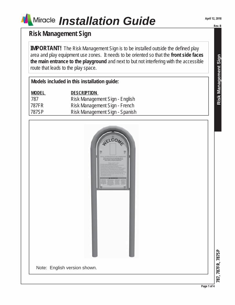
Ris
k M
anag
emen
t Sig
n
Risk Management Sign
Page 1 of 4
787,
787F
R, 78
7SP
April 12, 2018
Rev. BInstallation Guide
IMPORTANT! The Risk Management Sign is to be installed outside the defi ned play area and play equipment use zones. It needs to be oriented so that the front side faces the main entrance to the playground and next to but not interfering with the accessible route that leads to the play space.
Note: English version shown.
Models included in this installation guide:
MODEL DESCRIPTION 787 Risk Management Sign - English
787FR Risk Management Sign - French 787SP Risk Management Sign - Spanish
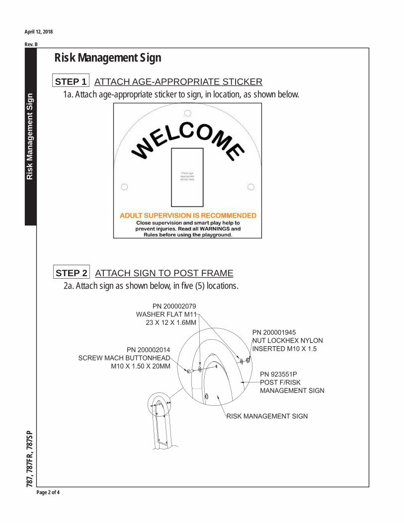
Page 2 of 4
Ris
k M
anag
emen
t Sig
n
Risk Management Sign
787,
787F
R, 78
7SP
April 12, 2018
Rev. B
2a. Attach sign as shown below, in fi ve (5) locations. STEP 2 ATTACH SIGN TO POST FRAME
1a. Attach age-appropriate sticker to sign, in location, as shown below. STEP 1 ATTACH AGE-APPROPRIATE STICKER
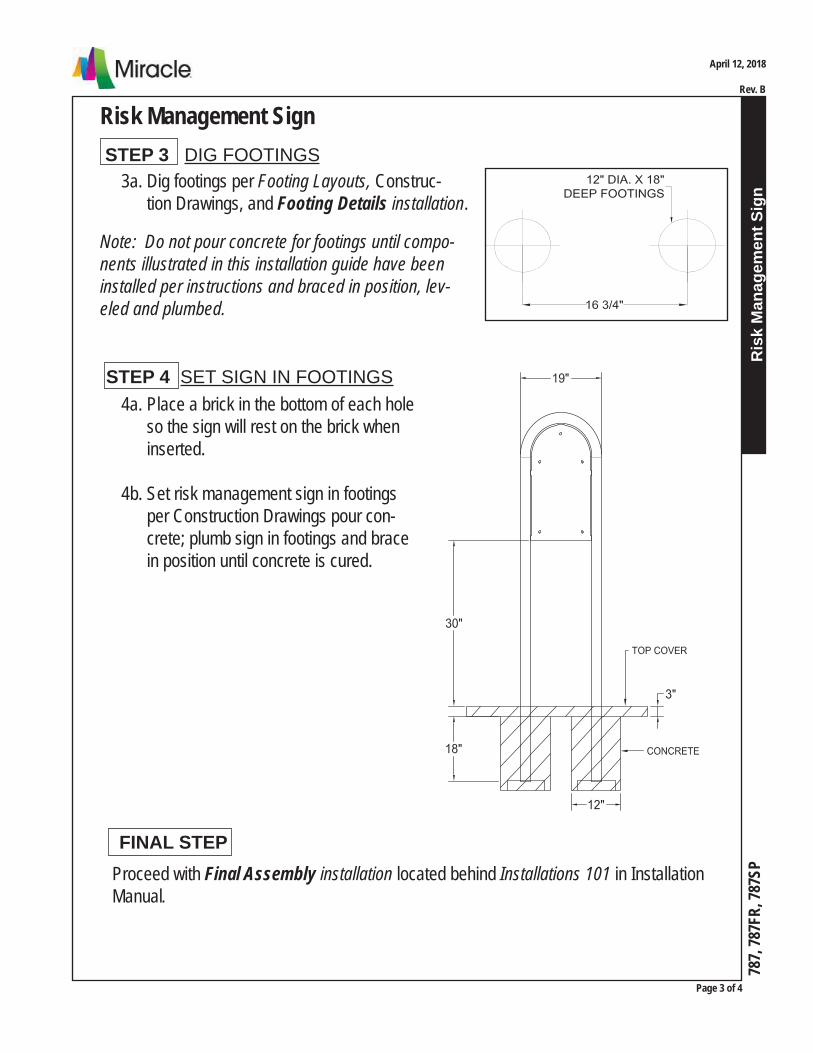
Ris
k M
anag
emen
t Sig
n
Risk Management Sign
Page 3 of 4
787,
787F
R, 78
7SP
April 12, 2018
Rev. B
3a. Dig footings per Footing Layouts, Construc- tion Drawings, and Footing Details installation.
Note: Do not pour concrete for footings until compo-nents illustrated in this installation guide have been installed per instructions and braced in position, lev-eled and plumbed.
STEP 3 DIG FOOTINGS
STEP 4 SET SIGN IN FOOTINGS 4a. Place a brick in the bottom of each hole so the sign will rest on the brick when inserted.
4b. Set risk management sign in footings per Construction Drawings pour con- crete; plumb sign in footings and brace in position until concrete is cured.
Proceed with Final Assembly installation located behind Installations 101 in Installation Manual.
FINAL STEP

Page 4 of 4
Ris
k M
anag
emen
t Sig
n
Risk Management Sign
787,
787F
R, 78
7SP
April 12, 2018
Rev. B
Bill of Material
Model 787QTY PART DESCRIPTION1 923551P POST F/RISK MANAGEMENT SIGN1 923560 PC F/787 RISK MNGMT ENGLISH
Parts Carton 9235601 923287 RISK MNGT SIGN PRINTED ENGLISH1 HW923551-1 HRDW PKG RISK MANAGEMENT SIGN S1/1
HW923551-1QTY PART DESCRIPTION5 200002014 SCREW MACH BUTTONHEAD M10 X 1.50 X 20MM10 200002079 WASHER FLAT M11 23 X 12 X 1.6MM5 200001945 NUT LOCK HEX NYLON INSERTED M10 X 1.5
Model 787FRQTY PART DESCRIPTION1 923551P POST F/RISK MANAGEMENT SIGN1 923558 PC F/787FR RISK MNGMT FRENCH
Parts Carton 9235581 923288 RISK MNGT SIGN PRINTED ENGLISH1 HW923551-1 HRDW PKG RISK MANAGEMENT SIGN S1/1
HW923551-1QTY PART DESCRIPTION5 200002014 SCREW MACH BUTTONHEAD M10 X 1.50 X 20MM10 200002079 WASHER FLAT M11 23 X 12 X 1.6MM5 200001945 NUT LOCK HEX NYLON INSERTED M10 X 1.5
Model 787SPQTY PART DESCRIPTION1 923551P POST F/RISK MANAGEMENT SIGN1 923559 PC F/787SP RISK MNGMT SPANISH
Parts Carton 9235591 923289 RISK MNGT SIGN PRINTED SPANISH1 HW923551-1 HRDW PKG RISK MANAGEMENT SIGN S1/1
HW923551-1QTY PART DESCRIPTION5 200002014 SCREW MACH BUTTONHEAD M10 X 1.50 X 20MM10 200002079 WASHER FLAT M11 23 X 12 X 1.6MM5 200001945 NUT LOCK HEX NYLON INSERTED M10 X 1.5

Final AssemblyKids' Choice, Tots' Choice, Center Stage, and City Parks Series Deck Systems & Misc.
Fin
al A
ssem
bly
Page 1 of 1
June 4, 2001 Rev. CInstallation Guide
714,
718
, ...
STEP 1
Plumb and level assemblies.
STEP 2
Secure Clamps to Posts with self-drilling screws andtighten all fasteners.
STEP 3
Trim all bolts. No more than two (2) threads may protrude after trimmingby installer. Peen ends smooth to touch.
STEP 4
Pour concrete in remainingFootings, and allow 72 hoursto cure.
STEP 5
Install cushioning material (protective surfacing)in, around and beneath areas required for unit.
STEP 6
Apply Warning and Manufacturer's I.D. labels, and Age Appropriate labels if included. Referto Installations 101.
FINAL STEP
Establish and adhere to a regular maintenance schedule, checking for loose ormissing bolts, worn parts, etc.
CONCRETE FOOTING
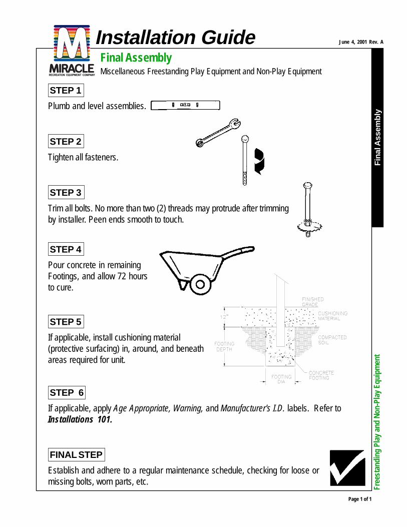
Final AssemblyMiscellaneous Freestanding Play Equipment and Non-Play Equipment
Fin
al A
ssem
bly
Page 1 of 1
June 4, 2001 Rev. AInstallation Guide
Free
stan
ding
Pla
y an
d No
n-Pl
ay E
quip
men
t
STEP 1
Plumb and level assemblies.
STEP 2
Tighten all fasteners.
STEP 3
Trim all bolts. No more than two (2) threads may protrude after trimmingby installer. Peen ends smooth to touch.
STEP 4
Pour concrete in remainingFootings, and allow 72 hoursto cure.
STEP 5
If applicable, install cushioning material(protective surfacing) in, around, and beneathareas required for unit.
FINAL STEP
Establish and adhere to a regular maintenance schedule, checking for loose ormissing bolts, worn parts, etc.
STEP 6
If applicable, apply Age Appropriate, Warning, and Manufacturer's I.D. labels. Refer toInstallations 101.

Qty Model/Component Description
1 * 7147342 PANEL SAFETY AGES 2-12
2 ** 111226BLU POST-SAFETY SIGN 2 3/8 OD X 73" LONG
1 ** 986570 PARTS CARTON SAFETY PANEL
1 HW986570-1 HRDW PKG SAFETY PANEL S1/1
1 ** 998212BEI SAFETY PANEL AGES 2-12
1 * 7185019 DECK TRIANGLE ATTACHES TO 3 POSTS MT II
2 ** 912254BEI 3.5" TC (6) 1/2 CLAMPS 1/1
2 HW912254-1 HRDW PKG 3.5 TC 3 S1/1
12 983856BEI CLAMP RING 3.5 DIA
1 ** 982072 PARTS CARTON 718-501
1 116021 LABEL MIRACLE ID - GENERIC
1 116022 LABEL WARNING - PLAYGROUND - ENGLISH
1 116039 LABEL MIRACLE ID - TOTS' CHOICE
1 116099 LABEL, PLAY SMART RULES
1 HW982072-1 HRDW PKG DK SPT S1/1
3 713550 STICKER TOP OF SURFACING
3 981722 DECK SUPPORT 3.5" OD TUBE
1 ** 988135BE TC -TRIANGULAR DECK FPS BE
2 * 7185029 DECK SQUARE ATTACHES TO 4 POSTS MT II
4 ** 912253BEI 3.5" TC (8) 1/2 CLAMPS 1/1
4 HW912253-1 HRDW PKG 3.5 4CLMP S1/1
32 983856BEI CLAMP RING 3.5 DIA
2 ** 982073 PARTS CARTON 718502
2 116021 LABEL MIRACLE ID - GENERIC
2 116022 LABEL WARNING - PLAYGROUND - ENGLISH
2 116039 LABEL MIRACLE ID - TOTS' CHOICE
2 116099 LABEL, PLAY SMART RULES
2 HW982073-1 HRDW PKG DK SPT S1/1
8 713550 STICKER TOP OF SURFACING
8 981722 DECK SUPPORT 3.5" OD TUBE
2 ** 988130BE TC- SQUARE DECK
5 * 7185494 POST 3-1/2"OD X 118" 4' DECKS
5 ** 995233BLU POST 3.5" OD(W/CAP)X13GAX118"
W. O. Page 1 of 7
Bill of Materials 8/28/2018 1:27:40 PM(Parts List)
Cust #: 9450L05Work Order: MR00112258
YOLO, COUNTY OF
137 N COTTONWOOD
WOODLAND, CA 95695
Model
Component
*
**
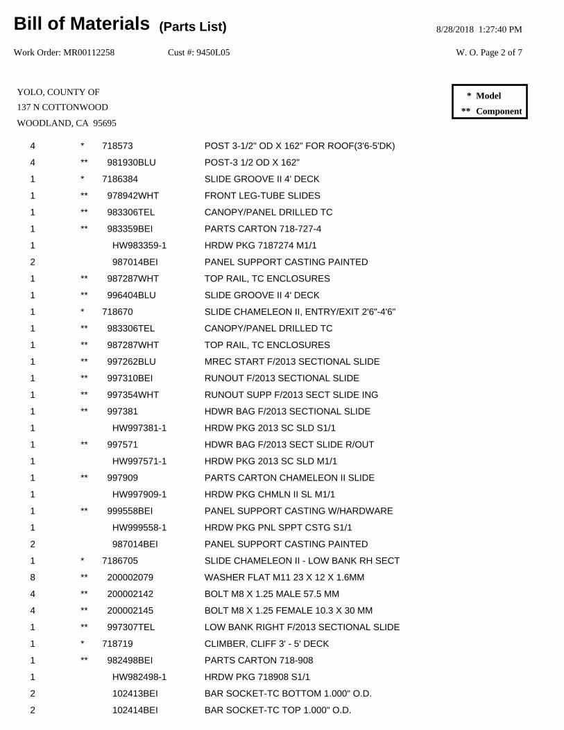
4 * 718573 POST 3-1/2" OD X 162" FOR ROOF(3'6-5'DK)
4 ** 981930BLU POST-3 1/2 OD X 162"
1 * 7186384 SLIDE GROOVE II 4' DECK
1 ** 978942WHT FRONT LEG-TUBE SLIDES
1 ** 983306TEL CANOPY/PANEL DRILLED TC
1 ** 983359BEI PARTS CARTON 718-727-4
1 HW983359-1 HRDW PKG 7187274 M1/1
2 987014BEI PANEL SUPPORT CASTING PAINTED
1 ** 987287WHT TOP RAIL, TC ENCLOSURES
1 ** 996404BLU SLIDE GROOVE II 4' DECK
1 * 718670 SLIDE CHAMELEON II, ENTRY/EXIT 2'6"-4'6"
1 ** 983306TEL CANOPY/PANEL DRILLED TC
1 ** 987287WHT TOP RAIL, TC ENCLOSURES
1 ** 997262BLU MREC START F/2013 SECTIONAL SLIDE
1 ** 997310BEI RUNOUT F/2013 SECTIONAL SLIDE
1 ** 997354WHT RUNOUT SUPP F/2013 SECT SLIDE ING
1 ** 997381 HDWR BAG F/2013 SECTIONAL SLIDE
1 HW997381-1 HRDW PKG 2013 SC SLD S1/1
1 ** 997571 HDWR BAG F/2013 SECT SLIDE R/OUT
1 HW997571-1 HRDW PKG 2013 SC SLD M1/1
1 ** 997909 PARTS CARTON CHAMELEON II SLIDE
1 HW997909-1 HRDW PKG CHMLN II SL M1/1
1 ** 999558BEI PANEL SUPPORT CASTING W/HARDWARE
1 HW999558-1 HRDW PKG PNL SPPT CSTG S1/1
2 987014BEI PANEL SUPPORT CASTING PAINTED
1 * 7186705 SLIDE CHAMELEON II - LOW BANK RH SECT
8 ** 200002079 WASHER FLAT M11 23 X 12 X 1.6MM
4 ** 200002142 BOLT M8 X 1.25 MALE 57.5 MM
4 ** 200002145 BOLT M8 X 1.25 FEMALE 10.3 X 30 MM
1 ** 997307TEL LOW BANK RIGHT F/2013 SECTIONAL SLIDE
1 * 718719 CLIMBER, CLIFF 3' - 5' DECK
1 ** 982498BEI PARTS CARTON 718-908
1 HW982498-1 HRDW PKG 718908 S1/1
2 102413BEI BAR SOCKET-TC BOTTOM 1.000" O.D.
2 102414BEI BAR SOCKET-TC TOP 1.000" O.D.
W. O. Page 2 of 7
Bill of Materials 8/28/2018 1:27:40 PM(Parts List)
Cust #: 9450L05Work Order: MR00112258
YOLO, COUNTY OF
137 N COTTONWOOD
WOODLAND, CA 95695
Model
Component
*
**

1 ** 983334WHT CLIFF CLIMBER, 5FT DECK
1 ** 990660TEL ARCH ENCLOSURE ASSY, CLIMBER
1 * 7187554 CLIMBER HONEYCOMB 4' DECK
4 ** 112719TEL POLYTUFF HONEY COMB
1 ** 720029WHT RUNG HONEY COMB TOP
3 ** 720033WHT MID-RUNG HONEY COMB
1 ** 981765TEL CHINNING BAR-37" TC
1 ** 984312BE BRACKET ASSEMBLY, COATED BE
2 ** 984315WHT HANDHOLD W/INSERT, 4' DECK, TC, PTD
2 ** 990950BEI PRT CRTN-TC BAR SOCKET 1.000" OD TUBE
2 102413BEI BAR SOCKET-TC BOTTOM 1.000" O.D.
2 102414BEI BAR SOCKET-TC TOP 1.000" O.D.
2 HW990950-1 HRDW PKG TC BAR SCKT 1 ST S1/1
1 ** 991948WHT PARTS CARTON, 7187554
1 HW991948-1 HRDW PKG 7187554 M1/1
2 984313WHT STUB ASSEMBLY, 1-13/16 IN., PAINTED
1 * 718796P1 BELL (POST MOUNT)
1 ** 990951BEI 3.5" OD TC BAR SOCKET 1.315"OD PIPE
1 102411BEI BAR SOCKET-BOTTOM 1.315" O.D.
1 102412BEI BAR SOCKET-TOP 1.315" O.D.
1 104285 SET SKT 3/8-16 X 3/8 18-8 SS
1 104403 BOLT 1/4-14 X 1 1/4 HEX WASHER TEK
2 104750 BOLT 1/4-20 X 5/8 BHCS 6 LOBE 18-8 SS
1 ** 990964BEI 3.5" OD TC VERSALOK CLAMP COMPLETE
2 104403 BOLT 1/4-14 X 1 1/4 HEX WASHER TEK
2 104749 BOLT 1/4-20 X 1 1/4 BHCS 6 LOBE 18-8 SS
2 104942 INSULATOR, SCREW, 1/4 DIA HOLE X 3/8
2 983856BEI CLAMP RING 3.5 DIA
1 ** 991824WHT PARTS CARTON 714 & 718-796-P1
1 104403 BOLT 1/4-14 X 1 1/4 HEX WASHER TEK
1 991819WHT BELL ASSEMBLY
1 * 7188172B PANEL BENCH BELOW DECK
1 ** 987479TEL BENCH PANEL
1 ** 987708BEI PARTS CARTON - TC BENCH PANEL
1 HW987708-1 HRDW PKG TC BENCH PANEL M1/1
W. O. Page 3 of 7
Bill of Materials 8/28/2018 1:27:40 PM(Parts List)
Cust #: 9450L05Work Order: MR00112258
YOLO, COUNTY OF
137 N COTTONWOOD
WOODLAND, CA 95695
Model
Component
*
**

4 102411BEI BAR SOCKET-BOTTOM 1.315" O.D.
4 102412BEI BAR SOCKET-TOP 1.315" O.D.
8 983856BEI CLAMP RING 3.5 DIA
2 ** 988358WHT TOP RAIL-TC CANOPY
1 * 71885149 TRANSFER POINT SQUARE 4' DECK
2 ** 114955WHT HANDRAIL EXTENSION-SWAGED 51 1/4"
1 ** 715264WHT RUNG LEG
1 ** 987145BE STEP, KC TP BTM FPS Bei
1 ** 990051WHT HANDRAIL-TRANS DECK,SQ.TRANS.PNT.
1 ** 990052WHT TRANSFER STEP HANDRAIL
1 ** 990057BE PVC DECK-TRANSFER POINT BE
2 ** 990133WHT DECK ENCLOSURE-TC TRANSFER POINT
1 ** 990304BEI PARTS CRTN-TC SQ. TRNFR PNT CLSD RAIL
1 HW990304-1 HRDW PKG TCSQ TNFR PT S1/3
1 HW990304-2 HRDW PKG TCSQ TNFR PT S2/3
1 HW990304-3 HRDW PKG TCSQ TNFR PT S3/3
2 102411BEI BAR SOCKET-BOTTOM 1.315" O.D.
2 102412BEI BAR SOCKET-TOP 1.315" O.D.
1 ** 990469BE PVC STAIR-4' SQUARE TRANSFER POINT BE
1 ** 990491WHT STAIR ENCL CLOSED SQ TP 4FT DK
1 ** 990492WHT STAIR ENCL CLOSED W/HOLE SQTP 4FT DK
1 * 7188614 ROOF SQUARE SHINGLE DOUBLE WALL
1 ** 112588TEL ROOF-60" SQUARE LOKVILLE
1 ** 981108 PARTS CARTON 4 POSTR ROOF
1 HW981108-1 HRDW PKG 7148614 S1/1
4 ** 981999BLU ROOF BRKT TC-FOR LV ROOF
1 * 718961P2 DELIGHT-O-SCOPE BINOCULARS TC POST MOUNT
1 ** 989716 PARTS CARTON - POST MNT DELIGHT-O-SCOPE
2 988749 DRIVE RIVET, NAIL-IN
1 ** 989958BLU ASSEMBLY BINOCULARS POST MOUNT, TC
1 * 718968 CLIMBER CURVED LOOP 3' OR 4' DECK
1 ** 982134WHT CLIMBER CURVED LOOP 3-4'DK
1 ** 982177TEL ARCHED ENCLOSURE W/BRACKETS
1 ** 982439BEI PARTS CARTON 718-815
1 HW982439-1 HRDW PKG 718815 M1/1
W. O. Page 4 of 7
Bill of Materials 8/28/2018 1:27:40 PM(Parts List)
Cust #: 9450L05Work Order: MR00112258
YOLO, COUNTY OF
137 N COTTONWOOD
WOODLAND, CA 95695
Model
Component
*
**
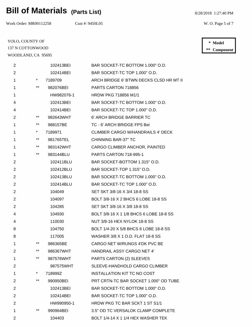
2 102413BEI BAR SOCKET-TC BOTTOM 1.000" O.D.
2 102414BEI BAR SOCKET-TC TOP 1.000" O.D.
1 * 7189709 ARCH BRIDGE 6' BTWN DECKS CLSD HR MT II
1 ** 982076BEI PARTS CARTON 718856
1 HW982076-1 HRDW PKG 718856 M1/1
4 102413BEI BAR SOCKET-TC BOTTOM 1.000" O.D.
4 102414BEI BAR SOCKET-TC TOP 1.000" O.D.
2 ** 982643WHT 6' ARCH BRIDGE BARRIER TC
1 ** 988157BE TC - 6' ARCH BRIDGE FPS Bei
1 * 7189971 CLIMBER CARGO W/HANDRAILS 4' DECK
1 ** 981765TEL CHINNING BAR-37" TC
1 ** 983142WHT CARGO CLIMBER ANCHOR, PAINTED
1 ** 983144BLU PARTS CARTON 718-995-1
2 102411BLU BAR SOCKET-BOTTOM 1.315" O.D.
2 102412BLU BAR SOCKET-TOP 1.315" O.D.
2 102413BLU BAR SOCKET-TC BOTTOM 1.000" O.D.
2 102414BLU BAR SOCKET-TC TOP 1.000" O.D.
2 104049 SET SKT 3/8-16 X 3/4 18-8 SS
2 104097 BOLT 3/8-16 X 2 BHCS 6 LOBE 18-8 SS
2 104285 SET SKT 3/8-16 X 3/8 18-8 SS
4 104930 BOLT 3/8-16 X 1 1/8 BHCS 6 LOBE 18-8 SS
4 110030 NUT 3/8-16 HEX NYLOK 18-8 SS
8 104750 BOLT 1/4-20 X 5/8 BHCS 6 LOBE 18-8 SS
8 117005 WASHER 3/8 X 1 O.D. FLAT 18-8 SS
1 ** 986365BE CARGO NET W/RUNGS 4'DK PVC BE
2 ** 986367WHT HANDRAIL ASSY CARGO NET 4'
1 ** 987576WHT PARTS CARTON (2) SLEEVES
2 987575WHT SLEEVE-HANDHOLD CARGO CLIMBER
1 * 718999Z INSTALLATION KIT TC NO COST
2 ** 990950BEI PRT CRTN-TC BAR SOCKET 1.000" OD TUBE
2 102413BEI BAR SOCKET-TC BOTTOM 1.000" O.D.
2 102414BEI BAR SOCKET-TC TOP 1.000" O.D.
2 HW990950-1 HRDW PKG TC BAR SCKT 1 ST S1/1
1 ** 990964BEI 3.5" OD TC VERSALOK CLAMP COMPLETE
2 104403 BOLT 1/4-14 X 1 1/4 HEX WASHER TEK
W. O. Page 5 of 7
Bill of Materials 8/28/2018 1:27:40 PM(Parts List)
Cust #: 9450L05Work Order: MR00112258
YOLO, COUNTY OF
137 N COTTONWOOD
WOODLAND, CA 95695
Model
Component
*
**
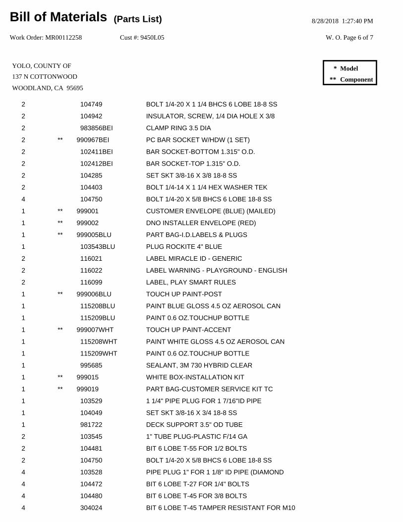
2 104749 BOLT 1/4-20 X 1 1/4 BHCS 6 LOBE 18-8 SS
2 104942 INSULATOR, SCREW, 1/4 DIA HOLE X 3/8
2 983856BEI CLAMP RING 3.5 DIA
2 ** 990967BEI PC BAR SOCKET W/HDW (1 SET)
2 102411BEI BAR SOCKET-BOTTOM 1.315" O.D.
2 102412BEI BAR SOCKET-TOP 1.315" O.D.
2 104285 SET SKT 3/8-16 X 3/8 18-8 SS
2 104403 BOLT 1/4-14 X 1 1/4 HEX WASHER TEK
4 104750 BOLT 1/4-20 X 5/8 BHCS 6 LOBE 18-8 SS
1 ** 999001 CUSTOMER ENVELOPE (BLUE) (MAILED)
1 ** 999002 DNO INSTALLER ENVELOPE (RED)
1 ** 999005BLU PART BAG-I.D.LABELS & PLUGS
1 103543BLU PLUG ROCKITE 4" BLUE
2 116021 LABEL MIRACLE ID - GENERIC
2 116022 LABEL WARNING - PLAYGROUND - ENGLISH
2 116099 LABEL, PLAY SMART RULES
1 ** 999006BLU TOUCH UP PAINT-POST
1 115208BLU PAINT BLUE GLOSS 4.5 OZ AEROSOL CAN
1 115209BLU PAINT 0.6 OZ.TOUCHUP BOTTLE
1 ** 999007WHT TOUCH UP PAINT-ACCENT
1 115208WHT PAINT WHITE GLOSS 4.5 OZ AEROSOL CAN
1 115209WHT PAINT 0.6 OZ.TOUCHUP BOTTLE
1 995685 SEALANT, 3M 730 HYBRID CLEAR
1 ** 999015 WHITE BOX-INSTALLATION KIT
1 ** 999019 PART BAG-CUSTOMER SERVICE KIT TC
1 103529 1 1/4" PIPE PLUG FOR 1 7/16"ID PIPE
1 104049 SET SKT 3/8-16 X 3/4 18-8 SS
1 981722 DECK SUPPORT 3.5" OD TUBE
2 103545 1" TUBE PLUG-PLASTIC F/14 GA
2 104481 BIT 6 LOBE T-55 FOR 1/2 BOLTS
2 104750 BOLT 1/4-20 X 5/8 BHCS 6 LOBE 18-8 SS
4 103528 PIPE PLUG 1" FOR 1 1/8" ID PIPE (DIAMOND
4 104472 BIT 6 LOBE T-27 FOR 1/4" BOLTS
4 104480 BIT 6 LOBE T-45 FOR 3/8 BOLTS
4 304024 BIT 6 LOBE T-45 TAMPER RESISTANT FOR M10
W. O. Page 6 of 7
Bill of Materials 8/28/2018 1:27:40 PM(Parts List)
Cust #: 9450L05Work Order: MR00112258
YOLO, COUNTY OF
137 N COTTONWOOD
WOODLAND, CA 95695
Model
Component
*
**
Total Weight: 2167.00
6 104964 RIVET, RATCHET, WHITE PLASTIC
25 104403 BOLT 1/4-14 X 1 1/4 HEX WASHER TEK
25 104942 INSULATOR, SCREW, 1/4 DIA HOLE X 3/8
3 ** 999132 PARTS CARTON - 2-12 LABEL - WHITE BOX
3 116036 LABEL - AGES 2-12 YEARS MREC
1 * 787Z RISK MANAGEMENT SIGN - ENGLISH
1 ** 923551BLU POST F/RISK MANAGEMENT SIGN
1 ** 923560 PC F/787 RISK MNGMT ENGLISH
1 923287 RISK MNGT SIGN PRINTED ENGLISH (DNO)
W. O. Page 7 of 7
Bill of Materials 8/28/2018 1:27:40 PM(Parts List)
Cust #: 9450L05Work Order: MR00112258
YOLO, COUNTY OF
137 N COTTONWOOD
WOODLAND, CA 95695
Model
Component
*
**
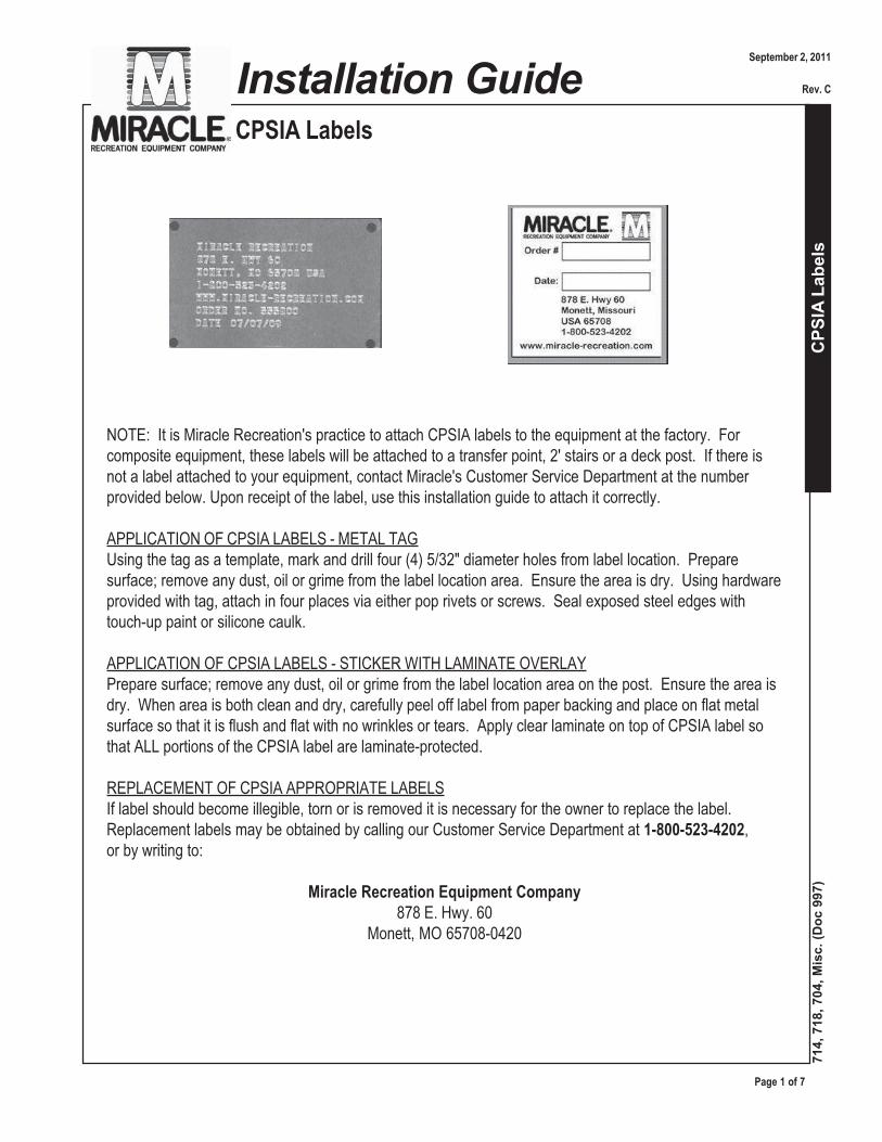
CPS
IA L
abel
s
CPSIA Labels
Page 1 of 7
714,
718
, 704
, Mis
c. (D
oc 9
97)
Installation Guide
NOTE: It is Miracle Recreation's practice to attach CPSIA labels to the equipment at the factory. Forcomposite equipment, these labels will be attached to a transfer point, 2' stairs or a deck post. If there isnot a label attached to your equipment, contact Miracle's Customer Service Department at the numberprovided below. Upon receipt of the label, use this installation guide to attach it correctly.
APPLICATION OF CPSIA LABELS - METAL TAGUsing the tag as a template, mark and drill four (4) 5/32" diameter holes from label location. Preparesurface; remove any dust, oil or grime from the label location area. Ensure the area is dry. Using hardwareprovided with tag, attach in four places via either pop rivets or screws. Seal exposed steel edges withtouch-up paint or silicone caulk.
APPLICATION OF CPSIA LABELS - STICKER WITH LAMINATE OVERLAYPrepare surface; remove any dust, oil or grime from the label location area on the post. Ensure the area isdry. When area is both clean and dry, carefully peel off label from paper backing and place on flat metalsurface so that it is flush and flat with no wrinkles or tears. Apply clear laminate on top of CPSIA label sothat ALL portions of the CPSIA label are laminate-protected.
REPLACEMENT OF CPSIA APPROPRIATE LABELSIf label should become illegible, torn or is removed it is necessary for the owner to replace the label.Replacement labels may be obtained by calling our Customer Service Department at 1-800-523-4202,or by writing to:
Miracle Recreation Equipment Company878 E. Hwy. 60
Monett, MO 65708-0420
September 2, 2011
Rev. C
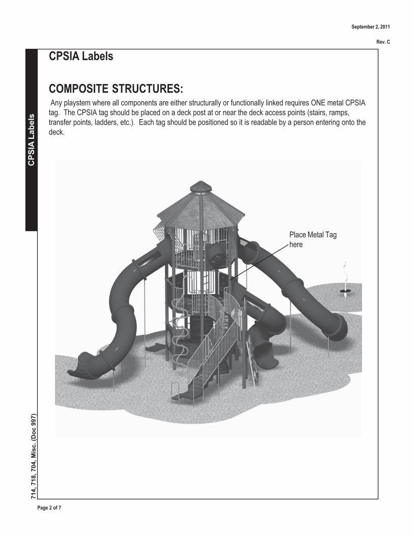
Page 2 of 7
CPS
IA L
abel
s
CPSIA Labels
714,
718
, 704
, Mis
c. (D
oc 9
97)
COMPOSITE STRUCTURES: Any playstem where all components are either structurally or functionally linked requires ONE metal CPSIAtag. The CPSIA tag should be placed on a deck post at or near the deck access points (stairs, ramps,transfer points, ladders, etc.). Each tag should be positioned so it is readable by a person entering onto thedeck.
Place Metal Taghere
September 2, 2011
Rev. C
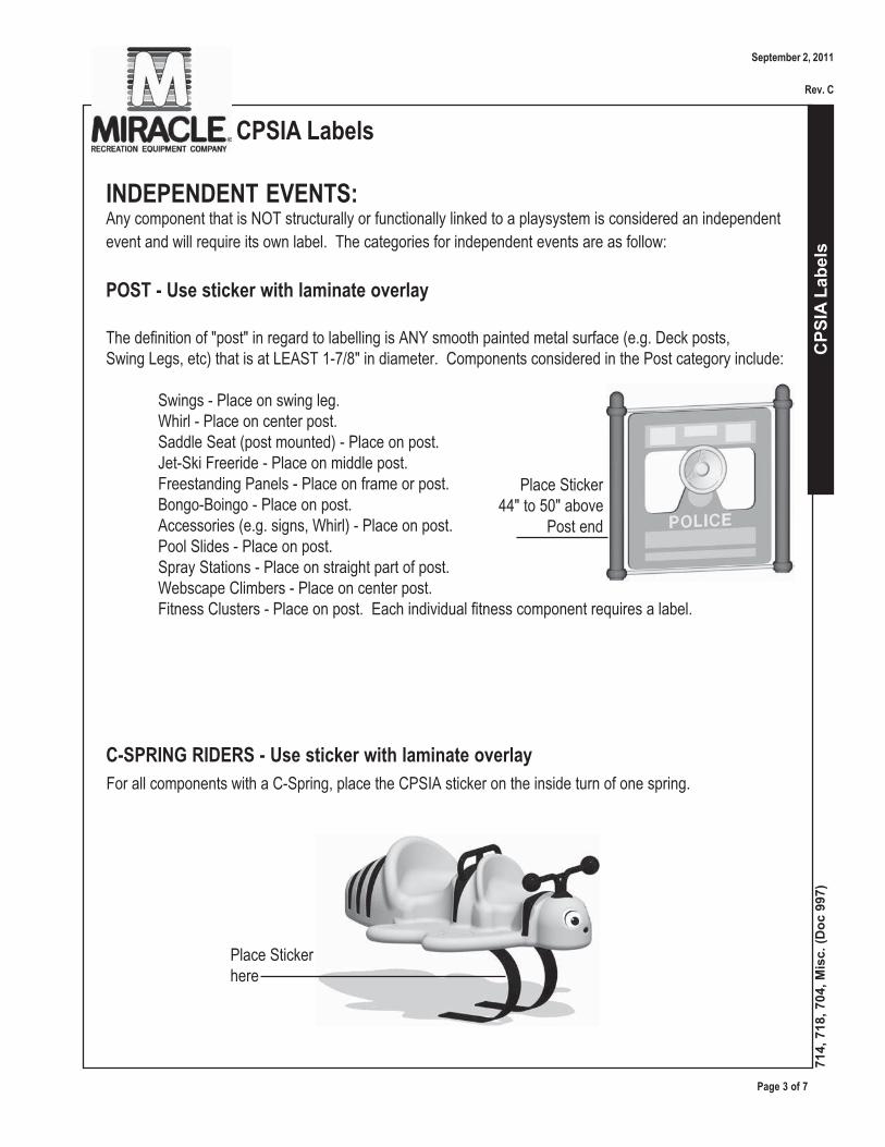
CPS
IA L
abel
s
CPSIA Labels
Page 3 of 7
714,
718
, 704
, Mis
c. (D
oc 9
97)
INDEPENDENT EVENTS:Any component that is NOT structurally or functionally linked to a playsystem is considered an independent
event and will require its own label. The categories for independent events are as follow:
POST - Use sticker with laminate overlay
The definition of "post" in regard to labelling is ANY smooth painted metal surface (e.g. Deck posts,Swing Legs, etc) that is at LEAST 1-7/8" in diameter. Components considered in the Post category include:
Swings - Place on swing leg.Whirl - Place on center post.Saddle Seat (post mounted) - Place on post.Jet-Ski Freeride - Place on middle post.Freestanding Panels - Place on frame or post.Bongo-Boingo - Place on post.Accessories (e.g. signs, Whirl) - Place on post.Pool Slides - Place on post.Spray Stations - Place on straight part of post.Webscape Climbers - Place on center post.Fitness Clusters - Place on post. Each individual fitness component requires a label.
C-SPRING RIDERS - Use sticker with laminate overlay
For all components with a C-Spring, place the CPSIA sticker on the inside turn of one spring.
Place Sticker44" to 50" above
Post end
Place Stickerhere
September 2, 2011
Rev. C

Page 4 of 7
CPS
IA L
abel
s
CPSIA Labels
714,
718
, 704
, Mis
c. (D
oc 9
97)
COIL SPRING RIDERS - Use metal tag or sticker with laminate overlay
For all components with a Coil Spring rider with a BOLTING PLATE, place the CPSIA sticker with laminateoverlay on the bolting plate between the bolts. If Coil Spring rider has no bolting plate, attach a metal tagdirectly to Rockite on underside area of rider. Coil Spring Rider category includes:
All Coil Spring Riders - Attach sticker with laminate overlay to Bolting plate OR metal tag to Rockite onunderneath side.Saddle Seat (Coil Spring) - Attach metal tag to Rockite on underneath side.Surfer - Attach metal tag to Rockite on underneath side.
Place Sticker here
Place Metal Tag onunderneath side
September 2, 2011
Rev. C
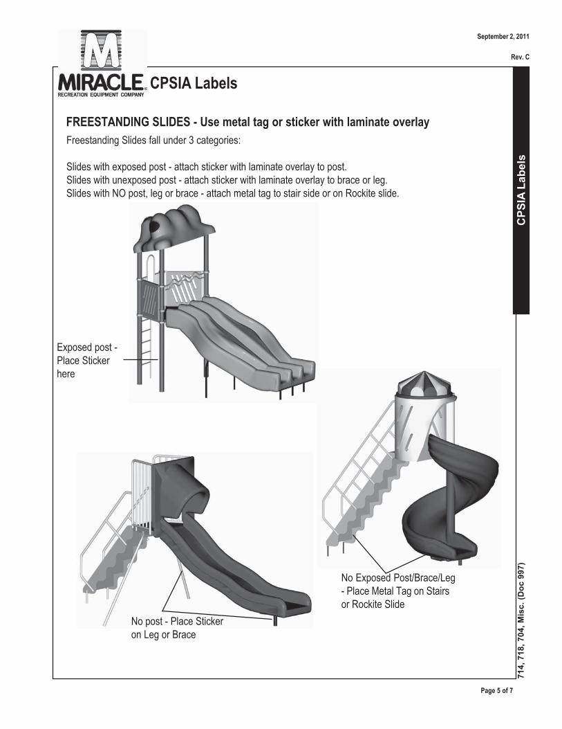
CPS
IA L
abel
s
CPSIA Labels
Page 5 of 7
714,
718
, 704
, Mis
c. (D
oc 9
97)
FREESTANDING SLIDES - Use metal tag or sticker with laminate overlay
Freestanding Slides fall under 3 categories:
Slides with exposed post - attach sticker with laminate overlay to post.Slides with unexposed post - attach sticker with laminate overlay to brace or leg.Slides with NO post, leg or brace - attach metal tag to stair side or on Rockite slide.
Exposed post -Place Stickerhere
No post - Place Stickeron Leg or Brace
No Exposed Post/Brace/Leg- Place Metal Tag on Stairsor Rockite Slide
September 2, 2011
Rev. C
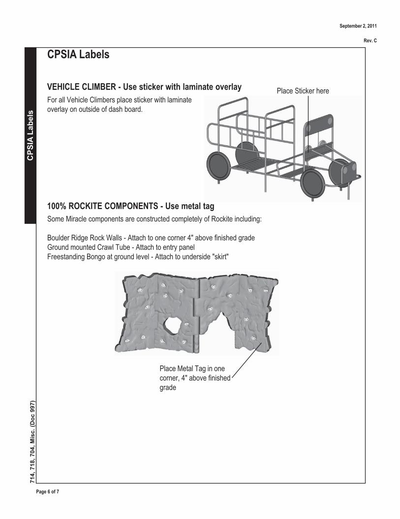
Page 6 of 7
CPS
IA L
abel
s
CPSIA Labels
714,
718
, 704
, Mis
c. (D
oc 9
97)
VEHICLE CLIMBER - Use sticker with laminate overlay
For all Vehicle Climbers place sticker with laminateoverlay on outside of dash board.
Place Sticker here
100% ROCKITE COMPONENTS - Use metal tag
Some Miracle components are constructed completely of Rockite including:
Boulder Ridge Rock Walls - Attach to one corner 4" above finished gradeGround mounted Crawl Tube - Attach to entry panelFreestanding Bongo at ground level - Attach to underside "skirt"
Place Metal Tag in onecorner, 4" above finishedgrade
September 2, 2011
Rev. C

CPS
IA L
abel
s
CPSIA Labels
Page 7 of 7
714,
718
, 704
, Mis
c. (D
oc 9
97)
SANDBOXES - Use metal tag or sticker with laminate overlay
Sandboxes include:
Mira-Therm2 Sandbox - Attach sticker with laminate overlay to painted metal wall side.Cloverleaf Sandbox - Attach sticker with laminate overlay to leg.Timber Sandbox - Attach metal tag directly to Rockite at outside corner.
Metal wall side -Place Sticker here
Outside Corner -Place MetalTag here
Place Sticker here
AFTER MARKET SERVICE PARTS - Use metal tag or sticker with laminate
All after market service parts will come with a separate installation guide that instructs installers to refer tothis CPSIA document for correct placement, dependent upon order. This secondary installation guide is locatedon the internal and installer websites.
GEODESIC CLIMBER - Use sticker with laminate overlay
Place sticker on underside plate, near ground level.
September 2, 2011
Rev. C

Post-Installation Check List D70165 Rev. B
Date of Completed Install: Work Order #:
Customer:
Project: City/State:
All labels properly affixed (CPSIA, age appropriate, top of surfacing and warning).
ALL CPSIA embossed labels for composite structures photographed for evidence of proper installation on equipment*.
All bolts, nuts, and set screws checked for tightness. All excess bolt threads cut and peened smooth to expose no more than two threads.
Unit has been wiped down to eliminate dust/dirt (soap and water may be necessary).
Equipment checked for installation guideline compliance.
Site cleaned with all construction trash removed.
Owner notified that installation was done according to manufacturer's specifications. Note any exceptions, e.g. that the owner must still provide safety surface, etc.
Touch-up paint, torque drive bits and spare parts left with the owner.
Owner reminded that equipment should not be used for 72 hours after installation to allow concrete to cure (if applicable) and/or protective surfacing must be installed.
If installation was not done according to specifications, please indicate changes and describe reason for doing so, and contact information for the person(s) who authorized the change.
Authorized by: Phone: Date:
Installer Signature Date:
Signed by owner or authorized customer Date:
*RETURN COMPLETED CHECKLIST AND PHOTOGRAPHS to MIRACLE CUSTOMER SERVICE by mail at 878 E. Hwy 60, Monett, MO 65708 or electronically to [email protected].
For questions contact Customer Service call 1-800-523-4202.

Related Documents


