Implementing Cryptography on TFT Technology for Secure Display Applications Petros Oikonomakos 1 , Jacques Fournier 1,2 , and Simon Moore 1 1 University of Cambridge, Computer Laboratory, William Gates Building, 15 JJ Thomson Avenue, Cambridge CB3 0FD, UK [email protected] 2 GEMPLUS, La Vigie, Avenue des Jujubiers, ZI Ath´ elia IV, 13705 La Ciotat Cedex, France Abstract. Several recent studies have underlined the need for trusted information displays in current and future personal devices. On the other hand, the display market is more and more dominated by low-cost flat- panel structures, driven by Thin-Film Transistor (TFT) circuits. Further, the quality of TFT-based electronics is constantly improving, allowing the fabrication of complicated electronic circuits on TFT technology. We have embarked on a project to implement cryptographic algorithms on polysilicon TFT technology. Our prototype designs will pave the way for secure display realisations combining cryptographic circuits and con- ventional pixel drivers on the same substrate. An experimental Data Encryption Standard (DES) coprocessor on polysilicon TFT technology is under development, while we are investigating a vector processor ar- chitecture to implement Elliptic Curve Cryptography (ECC). 1 Introduction Investigations related to secure and convenient, new or improved financial trans- action models are frequently published nowadays. Some of them [1, 2, 3] have identified the improvements in customer security that trusted displays have to offer. In this context, a display is trusted (or secure) if the content source can be sure that the distributed information will only be presented on the intended display. Alternatively, a secure display may be regarded as a means to verify that data is coming from a trusted source. When used in a customer’s personal electronic device (PDA, mobile phone, “smart device” etc.), such a display would form part of a secure communication path between a user and a business. An obvious way to develop secure displays is to equip them with decryption electron- ics, and have the source send encrypted information to them. An unauthorised party not having the adequate key(s) would thus not be able to extract clear display data or display any unauthorised content. On the display technology front, Organic Light Emitting Diodes (OLEDs) are emerging as a potential market substitute for Liquid Crystal Display (LCD) technology [4]. In the preferred active matrix configuration, both OLED and LCD pixel arrays are driven by Thin-Film Transistors (TFTs), fabricated on J. Domingo-Ferrer, J. Posegga, and D. Schreckling (Eds.): CARDIS 2006, LNCS 3928, pp. 32–47, 2006. c IFIP International Federation for Information Processing 2006

Welcome message from author
This document is posted to help you gain knowledge. Please leave a comment to let me know what you think about it! Share it to your friends and learn new things together.
Transcript

Implementing Cryptography on TFT Technologyfor Secure Display Applications
Petros Oikonomakos1, Jacques Fournier1,2, and Simon Moore1
1 University of Cambridge, Computer Laboratory, William Gates Building,15 JJ Thomson Avenue, Cambridge CB3 0FD, UK
[email protected] GEMPLUS, La Vigie, Avenue des Jujubiers, ZI Athelia IV,
13705 La Ciotat Cedex, France
Abstract. Several recent studies have underlined the need for trustedinformation displays in current and future personal devices. On the otherhand, the display market is more and more dominated by low-cost flat-panel structures, driven by Thin-Film Transistor (TFT) circuits. Further,the quality of TFT-based electronics is constantly improving, allowingthe fabrication of complicated electronic circuits on TFT technology. Wehave embarked on a project to implement cryptographic algorithms onpolysilicon TFT technology. Our prototype designs will pave the wayfor secure display realisations combining cryptographic circuits and con-ventional pixel drivers on the same substrate. An experimental DataEncryption Standard (DES) coprocessor on polysilicon TFT technologyis under development, while we are investigating a vector processor ar-chitecture to implement Elliptic Curve Cryptography (ECC).
1 Introduction
Investigations related to secure and convenient, new or improved financial trans-action models are frequently published nowadays. Some of them [1, 2, 3] haveidentified the improvements in customer security that trusted displays have tooffer. In this context, a display is trusted (or secure) if the content source canbe sure that the distributed information will only be presented on the intendeddisplay. Alternatively, a secure display may be regarded as a means to verifythat data is coming from a trusted source. When used in a customer’s personalelectronic device (PDA, mobile phone, “smart device” etc.), such a display wouldform part of a secure communication path between a user and a business. Anobvious way to develop secure displays is to equip them with decryption electron-ics, and have the source send encrypted information to them. An unauthorisedparty not having the adequate key(s) would thus not be able to extract cleardisplay data or display any unauthorised content.
On the display technology front, Organic Light Emitting Diodes (OLEDs)are emerging as a potential market substitute for Liquid Crystal Display (LCD)technology [4]. In the preferred active matrix configuration, both OLED andLCD pixel arrays are driven by Thin-Film Transistors (TFTs), fabricated on
J. Domingo-Ferrer, J. Posegga, and D. Schreckling (Eds.): CARDIS 2006, LNCS 3928, pp. 32–47, 2006.c© IFIP International Federation for Information Processing 2006

Implementing Cryptography on TFT Technology 33
an insulating substrate (typically glass). The TFT active area is formed eithertraditionally by hydrogenated amorphous Silicon (a–Si:H) [5], more recently bypolycrystalline Silicon (polysilicon, poly–Si) [4], or by continuous grain Silicon(CG–Si), described by Sharp as a next-generation variant of poly–Si [6]. Thelast two technologies demonstrate higher carrier mobility than a–Si:H, thus pro-ducing better quality transistors. It has therefore been possible to fabricate rel-atively complicated electronic circuits using both poly–Si and CG–Si [7, 8]. Notethat the production and material costs of TFT technology are much lowerthan that of conventional CMOS circuits. This can be understood even from thefact that the former use very cheap materials for the substrate (glass or plastic),while the latter require Silicon. Hence TFTs are economically preferable in largearea electronics applications with relatively low performance requirements.
A straightforward way to cryptographically secure an OLED display wouldbe to use a conventional CMOS cryptographic chip for the decryption of theimage information sent by the source. The decrypted information could then besuitably directed to the pixel driver array. The non-secure channel between thecryptographic chip and the driver array constitutes the weakest link in most oftoday’s security systems. However, given the recently demonstrated improvedcapabilities of modern TFT technologies (mentioned in subsection 3.1 of thispaper), it would be interesting to investigate whether cryptographic applicationscan be successfully implemented in such technologies. The motivation behindsuch an investigation is that consumer portable electronic devices usually occupyrelatively large areas. One could therefore use as much of the area as needed forthe actual display, while the rest can be occupied by TFT circuits controllingaccess to the display, by performing cryptographic operations. Figure 1 depictsan over-simplified configuration of a conceptual consumer smart device adheringto the above ideas. The bottom layer of the device in the figure is occupied
pixeldrivers
cryptographiccircuits
display
electionauthority
mediadistributor
e-shopor
vending terminal
Fig. 1. A smart consumer device with a secure TFT display

34 P. Oikonomakos, J. Fournier, and S. Moore
by TFT electronics, partly driving the pixels of an OLED display, and partlyperforming cryptographic functions. Of course, several other components (notshown in Fig. 1) would be needed in a consumer smart device, such as a keypad,I/O functionality, a radio antenna etc. The key idea illustrated by the figure,though, is the migration of cryptographic functionality from CMOS to TFTtechnology, allowing for better area use, promising lower production cost, andcompleting the end-to-end security chain. The figure also shows three examplesof parties that, depending on the application scenario, may communicate withthe smart device and would therefore require use of the display; a few suchapplications will be explained in Section 2.
The rest of this paper is organised as follows. Section 2 establishes the needfor secure displays by reviewing a few relevant works. Section 3 provides a briefup-to-date presentation of display technology and TFT drivers, as well as anoverview of recent developments in TFT circuits not directly related to displays.In Section 4 we propose our idea for a cryptographic device on poly–Si TFTtechnology. We report our progress in the direction of a first DES coprocessorprototype, together with our investigations towards a vector processor archi-tecture for Elliptic Curve Cryptography. Section 5 deals with low-level designconsiderations, particularly by presenting a Programmable Logic Array (PLA)configuration and detailing its operation. Finally, section 6 concludes the paper.
2 The Need for Secure Displays
In 1995, Yee and Tygar proposed the use of secure coprocessors in electroniccommerce [1]. When used in a point-of-sale terminal scenario, the coprocessor(e.g. a smart-card) communicates with the terminal, the customer reviews thetransaction on the terminal display and authorises it using the terminal interface.However, there can be no guarantee about the integrity of the terminal display.It is possible that the customer may be reviewing a transaction of a certainamount, and yet the terminal may be charging the card a different amount. Thiscan be either due to a violation of the terminal security by criminal activity, oreven due to merchant fraud. As the authors of [1] mention, the solution to thatwould be a private visual communication path between the smartcard processorand the end user. An information display on the user side is therefore needed,that would only present data received from the card. Such a trusted displaywould ensure that the user indeed authorises the same transaction that his orher own card is about to implement.
In a recent patent application [3], a cashless payment method is advocated,using a remote customer terminal (mobile phone, PDA or related apparatusencompassing user interfaces) to communicate with a trader station (e.g. super-market till) and a central station (e.g. bank). The desired amount of money isfirst read into the trader station, in a conventional way (keyed-in or scanned),and then transmitted to the central station through a data line. The customerreviews the transaction on the trader station display. If the amount is correct,he or she uses the mobile terminal to wirelessly send a unique identifier both

Implementing Cryptography on TFT Technology 35
to the trader station and to the central station. In response to that, the centralstation again wirelessly transmits the transaction details to the customer, to beconfirmed on the mobile terminal display. Payment proceeds following user au-thorisation from the mobile terminal to the central station. It can be argued thatthis model is more secure than that of the previous paragraph, since the usereffectively authorises the transaction twice, reviewing payment details submittedfrom two different sources. Again, however, it is important that the display onthe mobile terminal can be trusted to only present information received from thecentral station. Otherwise the whole model would be vulnerable to “man-in-the-middle” attacks [2], should an attacker interfere between the central station andthe customer. Therefore, the mobile terminal will need to be a “smart device”with a secure display.
In 1998 a group of European companies formed the FINancial TransactionalIC Card READer (FINREAD) Consortium [9]. Their objective ever since hasbeen to reinforce the level of smartcard security through the specification of asmartcard reader connectable to personal computers, to facilitate home-basede-commerce. Interestingly, the first FINREAD technical specifications mandate,among others, a secure display for the reader. Thus, the consortium of businessexperts recognise the importance of the integrity of data presented to the user. Ina recently accepted paper, Hiltgen et al. [2] describe how such a reader could beused for secure internet banking. In effect, all communication between the cardand the bank takes place through the reader and its secure interfaces. The PCplays no active role in manipulating (displaying, encrypting) the card’s details.Further, simple knowledge of the card number and details are no longer enoughfor a malevolent party to access customer accounts, since the bank server onlyauthenticates users by exchanging encrypted card information with the cardthrough the reader.
In another application area, Hortmann published a short tutorial on longdistance e-voting [10]. He identifies the problem of potential communicationspoofing between a voter’s PC monitor and the election authority by onlineattackers, which is very similar in nature to equivalent scenarios in e-banking.Furthermore, in e-voting it is important not only that the voter sees the correctinformation on his or her display, but also that nobody else can see the infor-mation (for reasons of vote anonymity). Once again, the use of secure displaysfor end-user voting components is advocated. The author of [10] envisions futurePDAs armed with trusted displays functioning as “Personal Security Devices”(PSDs) to realise secure e-voting.
Since 2003, the Open Mobile Alliance (OMA), an industry forum dealing withmobile services, has been working on Digital Rights Management (DRM) schemesto securely distribute and protect data on mobile terminals [11]. Their DRMspecification details functional models for the distribution of purchased mediaapplications to mobile consumer devices. In order for such a business model tooperate profitably, it is imperative that the distributor be certain that the appli-cation can only be enjoyed by the customer, and not widely distributed further. If
36 P. Oikonomakos, J. Fournier, and S. Moore
the application contains images, then encrypting them such that only the buyer’ssecure display can show them will provide a good solution to this problem.
Through the examples reviewed in the above, this section has demonstratedhow secure displays on smart devices can enable trusted communication of pri-vate, sensitive data through public networks, in a variety of applications, includ-ing e-commerce, e-voting, and wireless distribution of media applications.
3 Display Technology and TFTs
Liquid Crystal (LC) based components currently dominate the flat-panel displaymarket. LCDs operate by modulating light generated by a back-light source. Inrecent years, an alternative emissive technology has been rapidly developing:Organic Light Emitting Diode (OLED) displays. Compared to LCDs, OLEDsdemonstrate higher luminous efficiency, brightness, lower production costs andlower operating voltage requirements, in addition to a larger viewing angle. AnOLED is a multi-layered electronic structure. One layer is fabricated from anelectron transporting material; another from a hole transporting material. Inbetween there exists another layer where the carriers recombine and the excessenergy is released as light. The whole structure is often sandwiched betweena hole injecting electrode and an electron injecting electrode. Current passingthrough the OLED causes the emission of light [4].
The pixels of an LC or OLED display can be driven by either a passiveor an active matrix (PM or AM respectively), formed by a horizontal addressline and a vertical data line. In PM driving, the LCD elements or OLEDs aredirectly connected to the lines, while AM displays employ actual driving circuits.LCD pixels are voltage-driven; therefore PM driving is a valid low-cost option. Incontrast, OLEDs are current-driven. Further, all pixels require a uniform currentflow, in order for the OLEDs to provide uniform brightness. It is very difficultto achieve uniform current unless some transistor-based driver circuit is used.It is therefore in practice mandatory to apply active matrix driving of OLEDdisplays. Given the physical dimensions of displays, in most cases it would beeconomically unwise to use CMOS driving circuits for the active matrix. This isthe application area where TFTs on insulating and cheap substrates are useful.
From the above description, it is evident that good quality current sourcesto be used as AM pixel drivers are the most obviously needed TFT circuits. Itis desirable that the drivers not only provide constant current initially, but alsocontinue to do so throughout the expected display lifetime, regardless of anyTFT threshold voltage shift over time. A number of designs have been proposedin the literature for this purpose. References [5, 12] deal with a–Si:H TFTs.These TFTs do not demonstrate very good electronic properties. They suffer inparticular from low carrier mobility (lower than 1cm2/V-s), thus requiring verywide channels to allow sufficient current flow (e.g. Nathan et al. [5] report TFTswith channels as wide as 1000µm). Further, p-channel TFTs are not available ina–Si:H technology [4]. Nevertheless a–Si:H TFT technology is mature and stilldraws significant research attention. In this context, reference [12] proposes a

Implementing Cryptography on TFT Technology 37
constant current source composed of 4 TFTs and a storage capacitor. Reference[5] shows an improved version, requiring no storage capacitor.
The driver designs mentioned in the previous paragraph can equally well beused in poly–Si TFT based displays. Poly–Si TFTs demonstrate much greatermobility values than their a–Si:H counterparts (typically by more than an orderof magnitude). This allows for much narrower transistors (W/L=2 is achievable).Many poly–Si TFT processes are also able to produce p-channel devices. In [4],Stewart et al. describe a number of refinements to conventional poly–Si TFTfabrication processes that were shown to lead to more uniform TFT character-istics. This way, brightness uniformity can be improved even for driver circuitsconsisting of only 1 or 2 TFTs.
It is noteworthy that an interesting family of low-temperature poly–Si TFTprocesses has recently been developed (termed LTPS–TFT) [6]. These processesenable the relatively easy fabrication of TFT circuits on non-conventional sub-strates, e.g. plastic or various flexible substrates.
3.1 Recent TFT Applications
TFT electronics unrelated to information displays are not widespread. However,the availability of p-channel devices, the continuous improvement in electronicproperties and the reduced fabrication costs, in addition to unique characteristicssuch as manufacturability on flexible substrates have recently triggered a certaindegree of research activity on other potential uses of poly–Si TFTs, LTPS–TFTsand CG–Si TFTs. Some characteristic examples are presented in this section.
Hashido et al. [13] developed a capacitive fingerprint sensor using LTPS–TFTtechnology. They initially observe that conventional optical fingerprint authen-tication systems are very expensive and not portable. Direct-contact fingerprintsensors are a portable alternative; implementing such sensors on TFT technologyadditionally lowers the production cost. Their sensor is based on the assumptionthat the capacitance between a given area of the human finger and a sensor platethat the finger touches depends on the morphology of the area (i.e. whether it isa “valley” or a “ridge”). A simple 1-TFT sensor cell is configured that, togetherwith a read-out TFT, converts this capacitance to voltage. The overall sensorchip comprises a matrix of such sensor cells, as well as buffers and shift regis-ters that control the continuous scanning of all rows and columns of the matrix.Their experimental results undoubtedly support their sensing method.
Estrela et al. [14] experiment with poly–Si TFTs for biosensor applications.They observe consistent and repeatable threshold voltage shifts in the current-voltage (I-V) characteristics of TFTs when they come in contact with certainbiochemical agents. Based on this, they demonstrate the potential usefulness ofpoly–Si TFTs as inexpensive disposable pH sensors, penicillin sensors, as well asDNA hybridization sensors.
In a more conventional application, Lee et al. [8] present a full Z80 CPU(8-bit) developed using CG–TFT technology on a glass substrate. CG–TFTstypically demonstrate three times the carrier mobility of LTPS–TFTs [6]. Thepresented chip comprises 13000 TFTs and runs at 3 MHz when powered at 5
38 P. Oikonomakos, J. Fournier, and S. Moore
Volts. The authors of [8] report it as the first publicly-announced successfulstep in the direction of realising full-scale electronic systems on glass substrates(“Systems on Panels”).
Finally, Karaki et al. [7] announced the fabrication of an 8-bit LTPS asyn-chronous microprocessor, named ACT11. Operating asynchronously provides ro-bustness against variations in TFT I-V characteristics as well as power savings.The chip nominally operates at 5 Volts.
4 Developing Cryptography on Poly–Si TFTs
The discussion so far established that as TFT technologies mature, they canaccommodate more and more complicated digital electronics applications. Theintegration of substantial functional circuits and display drivers on the same sub-strate appears to be a matter of time. The state-of-the-art rapidly approaches astage where high-volume production will demand serious CAD tool support forTFT chip production lines. Motivated by these observations, we have embarkedon a research project to implement cryptographic functionality on poly–Si TFTtechnology. We expect this concept to be particularly useful for the develop-ment of secure displays, to be used in financial and other future applicationssuch as these described in Section 2 of this paper. The current capabilities ofTFTs cannot cope with clock frequency values above a few MHz (or equivalentasynchronous throughput). However, most of these applications could easily beaccommodated by static and slow displays without seriously impairing customersatisfaction. In addition, TFT characteristics are improving rapidly. Thereforeit is expected that the commercial relevance of TFT electronics applications willincrease continuously in the future. In other words, cryptographic TFT chipsmay in the future be used even in scenarios requiring fast displays.
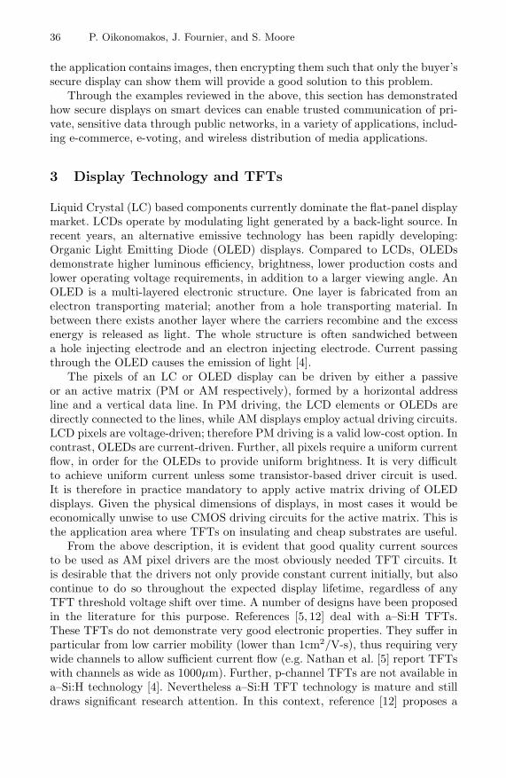
To investigate about the implementation of cryptographic functions on poly–Si TFTs, we chose to focus on the simple concept of displaying information
Input buffer
Input controllerDES coprocessor DcoP
ECC vector processorVeMICry
Frame buffer
display
user input
Fig. 2. Cryptographic chip architecture

Implementing Cryptography on TFT Technology 39
encrypted using DES. In order to securely distribute and refresh the DES keyswe include ECC capabilities in our scheme as illustrated in Fig. 2. Our chip willwork in the following fashion.
– The data received in the input buffer is assumed to be encrypted accordingto the Data Encryption Standard (DES) [15].
– The 56-bit DES keys are transmitted encrypted using an asymmetricpublic-key scheme, in our case Elliptic Curve Cryptography. In the field ofpublic-key cryptography, Elliptic Curves (ECs) have performance and key-size advantages over the RSA scheme [16]. We therefore choose them for ourdesign.
– The environment first provides a number of encrypted DES keys to the inputbuffer.
– The input controller routes these keys to the ECC processor VeMICry shownin the figure.
– Processor VeMICry is being designed to include special hardware to imple-ment modular arithmetic needed for ECC. Its overall architecture accordsto the vector processor model [17]. More details are provided in subsection4.2 of this paper.
– While VeMICry is decrypting the keys using its private key, the environmentprovides the actual DES-encrypted data to the input buffer.
– The input controller then makes sure the data is routed to the DES coproces-sor (DcoP in the figure).
– Coprocessor DcoP is a pure hardware module and makes heavy use of PLAsas building blocks. More details on its architecture are given in subsection4.1 of this paper.
– When VeMICry finishes decrypting the keys, it sends them to the DES co-processor, to be used for data decryption.
– Coprocessor DcoP then performs DES decryption and writes the decrypteddata to the output buffer. In the figure the buffer is termed frame buffer,since the chip is intended to feed display drivers.
– While DcoP performs decryption, the environment provides new keys to thechip input. The keys are again sent to VeMICry and a new cycle of operationbegins.
56-bit DES keys are no longer considered to be completely secure [18]. How-ever, one could envisage to refresh the keys frequently enough to discourage anyattack on the DES. In a real application, one could use 3-DES or AES; our chipis simply a proof-of-concept of cryptography using TFTs. The security of theoverall scheme will also depend on the security of the ECC processor (and itsresistance to side-channel attacks) and how the device’s private key is stored.If implemented and combined with pixel drivers, the architecture will providecryptographic protection to the display. With those cryptographic capabilities,we could for example make sure that only “authenticated” users can access thedisplay or that distributed images are only visible on that particular display.
Of the blocks shown in Fig. 2, VeMICry and DcoP are currently under devel-opment. The input controller is expected to be nothing more complicated than

40 P. Oikonomakos, J. Fournier, and S. Moore
a state machine, routing a fixed number of input packets to VeMICry, followedby another fixed number of packets to DcoP. The following subsections 4.1 and4.2 provide architectural details on the design of the two processors.
4.1 The DES Coprocessor
The DES coprocessor is being designed purely as a hardware module, comprisingthree blocks, namely the key schedule, round block, and the controller. It isa straightforward implementation, shown in the block diagram of Fig. 3. Thecoprocessor receives a 64-bit encrypted data input, directed to the round block,and a 56-bit key, directed to the key schedule block. The environment (ultimatelythe input controller of Fig. 2) also raises two flags – I and K – as soon as validdata and a valid key have been fed to DcoP. As soon as I and K are raised,the controller state machine orders the key schedule to compute a subkey, againby raising a suitable flag. The key schedule block computes the subkey andfeeds it to the round block, while informing the controller about computationcompletion. The controller further signals to the round block that the subkey isready. Upon receiving the signal, the round block responds by using the subkeyto produce the partial result, and subsequently informs the controller. The sameprocess is repeated sixteen times for all DES rounds [15]. After all rounds, thedecrypted output is available at the round block output. The controller informsthe environment and waits for new input and key values. Throughout the process,the controller asserts or deasserts suitable signals to make sure the key scheduleperforms single or double shifts depending on the current round.
It is evident that this simple model can easily be adjusted to perform encryp-tion instead of decryption, by performing left or right shifts in the key scheduleblock. Further, it can also easily be amended to implement triple DES insteadof standard DES.
Behavioural Verilog [19] models for the DcoP blocks have been developed andconfirmed by simulation. The actual layout is currently under development. Theresulting chip will be the first, to our knowledge, cryptographic application on
DES coprocessor
controller
key schedule
round block
input
output
Fig. 3. DES coprocessor block diagram

Implementing Cryptography on TFT Technology 41
poly–Si TFT technology, and at the same time the first poly–Si TFT chip tofeature a 64-bit datapath. It will test the feasibility of cryptography on TFTs andbuild up our confidence towards full integration of the architecture of Fig. 2. Notethat this design can be easily tweaked to execute stronger encryption algorithmslike DESX.
4.2 A Vector Processor for Elliptic Curve Cryptography
This section provides information about the architecture and functional model ofthe vector processor with cryptographic support shown in Fig. 2. We have usedthe acronym VeMICry, for Vectorial MIPS for Cryptography [20]. In essence,VeMICry comprises a simple MIPS-I processor [21] implementing usual, “scalar”instructions, together with a vector coprocessor for the vector instructions. Thesimplified block diagram of Fig. 4 depicts this idea. The overall processor worksvery much as a standard MIPS as regards conventional instructions; when vectorinstructions are encountered in the program then the decoder directs them to thevector coprocessor. As the name suggests, vector instructions operate on vectorsof registers rather than on individual registers. A total of 17 vector instructionshave been defined for VeMICry; a full list is provided in [20]. A few examples –relevant to public key cryptography – are:
– Unsigned Vector Addition: adds the contents of respective elements (regis-ters) of two vectors and writes the result to a third, while propagating carriesfrom the ith element to the i+1st.
– Vector-Scalar Unsigned Addition: adds a scalar value – stored in a singleregister – to each vector element and writes the result to a target vector.
– Vector-Scalar Arithmetic Multiplication: multiplies a vector by a scalar valuewhile propagating carries. The result is written to a target vector.
– Vector-Scalar Polynomial Multiplication: multiplies a vector by a scalar valuewithout carry propagation. The result is written to a target vector.
Clearly, the last two instructions can be used to implement modular multi-plication, based on Montgomery’s reduction algorithm [22], in prime or binary
programmemory
fetchunit
decoder
MIPSinstructionexecution
vectorcoprocessor
Fig. 4. ECC vector processor block diagram

42 P. Oikonomakos, J. Fournier, and S. Moore
Galois Fields. This multiplication is the most critical opearation of EC pointmultiplication required for EC decryption.
The reason why we chose a vector architecture is that cryptographic algo-rithms in general and ECC in particular operate on very wide datapaths andlong precision numbers. Decomposing the data into vectors of registers of smallerwidths and working on vectors and vector elements in parallel is expected toincrease performance. Further, a vector processor datapath is modular and scal-able, thus can easily be deployed in a variety of applications. Finally, a vectorprocessor has a simpler control path and scheduling logic than other superscalarprocessors, thus reducing power dissipation [17, 23]. Figure 5 shows the “heart”of the vector coprocessor, that is the vector register file together with vectorprocessing units (VPUs) to implement the instructions. Naturally, the coproces-sor also needs peripheral control logic not shown in the figure. In essence, thislogic will implement a vector instruction pipeline, separate from and communi-cating with the scalar MIPS pipeline (Fig. 4). Parameters in the design of thecoprocessor include the number of vectors q, the number of elements per vectorp, and the number of processing units r (all three shown in Fig. 5), as well asthe register bit-width, currently fixed at 32. The choice of these parameters willinfluence the processor performance, area, and degree of parallelism. In order toexplore the trade-offs between these characteristics, we have built a functionalmodel of the VeMICry using the ArchC simulation tool [24]. Details and simula-tion results can be found in [20], showing significant performance improvementswhen the Montgomery algorithm runs on the vector processor model, comparedto equivalent realisations on a purely scalar, conventional MIPS.
A Verilog model for the vector processor of Fig. 4 is under development. Thearchitecture will allow us to work on datapaths up to 256 bits wide.
Note that the VeMICry functional model is not restricted to modular mul-tiplication, ECCs or public key cryptography; the AES algorithm [25] has alsobeen simulated on it and again improvements were demonstrated in [20]. While
::::
::::
::::
::::
::::
..........
..........
::::
..........
..........
::::
::::
::::
..........
..........
.................
.................
VPUrVPU2VPU1
V0
V1
V2
Vq-2
Vq-1
[0] [1] [r-1][r][r+1] [2r-1] [p-r][p-r+1] [p-1]VECTORS
E L E M E N T S
Fig. 5. Vector register file and connections to vector processing units
Implementing Cryptography on TFT Technology 43
in this particular project it is employed for ECC decryption, it should be re-garded as a scalable, high performance processor architecture employable in avariety of cryptographic applications.
5 Low-Level Design Considerations
Instead of randomly placed logic gate realisations, in our DES design we areheavily relying on regular structures, in particular PLAs. Due to their geometri-cally regular layout, PLAs demonstrate timing predictability and controllability.Therefore they are often used in modern CMOS design flows to achieve quicktiming closure [26]. In these dynamic-logic structures, power is dissipated onlyimmediately after clock edges [27]. Therefore, the PLA outputs do not experi-ence data-dependent power glitches; this can be regarded as a counter measureagainst side-channel attacks. In line with the recommendations of [28], we thusprovide a degree of security “by design”. This may not be very relevant in thecase of the architecture in Fig. 2 as in practice an attacker would rather extractthe ECC private key than the DES secret keys which are refreshed frequently.However, it is definitely a positive feature for our coprocessor as such, should itbe used to implement DES, DESX or triple DES alone.
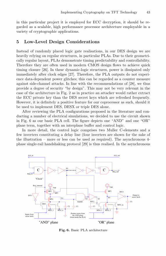
After reviewing the PLA configurations proposed in the literature and con-ducting a number of electrical simulations, we decided to use the circuit shownin Fig. 6 as our basic PLA cell. The figure depicts one “AND” and one “OR”plane term, together with an interplane buffer and control logic.
In more detail, the control logic comprises two Muller C-elements and afew inverters constituting a delay line (four inverters are shown for the sake ofthe illustration – more or less can be used as required). The asynchronous 4-phase single-rail handshaking protocol [29] is thus realised. In the asynchronous
C1 C3
C4
C2
X4
"Clock"
D1......
X3X2X1
INV3
INV1
INV2NAND
MP3
MN4_m
MN4_1 MN4_2MN2_1 MN2_n
MN3
MN1
MP2MP1
Req_internal
Output toasync latch
Vdd
......
Product terms fromthe AND plane
(from inside the PLA)
"OR" plane"AND" plane
......
Inputs fromasync latch
......
......
Vdd
Req_out
Ack_outAck_in
Req_in
CC
Fig. 6. Basic PLA architecture

44 P. Oikonomakos, J. Fournier, and S. Moore
operation context, the PLA is treated as combinational hardware handlingbundled-data coming from an asynchronous latch. The PLA output is also con-sidered to feed the latch of the next logic stage. The PLA is for the most part anasynchronous counterpart of the synchronous design presented by Wang et al.[27]. Indeed, if a clock was applied as shown in the figure (“clock”) instead of theasynchronous control signals, then we would have a perfectly working synchro-nous PLA. For our project, we choose an asynchronous implementation. This isfirstly because it is difficult to route a clock distribution network throughout thechip, given that TFT technologies rarely use more than two metal layers [13].Further, in line with Karaki et al. [7], we acknowledge the importance of I-Vcharacteristic variation tolerance that asynchronous design offers.
The PLA is implemented using n- and p-channel TFTs (nTFTs and pTFTsrespectively) in dynamic logic configuration and as such works in two phases,namely “precharge” and “evaluate”. When Req internal=0, the circuit is in theprecharge phase, and points X1 and X4 are driven to Vdd (the latter after twoinverters’ delay). In the subsequent evaluate phase (Req internal=1), the pull-down network of nTFTs in the AND plane determines the logic value at X1.After two inverter delays, this value is allowed to propagate to the OR planethrough the interplane buffer composed of the NAND gate and inverter INV2.The OR plane pull-down network then determines the ultimate PLA output.Capacitors C1 – C3 in the figure model parasitics, corresponding to long linesin the actual layout [27], while C4 signifies the output load.
While the PLA operation described above is typical of dynamic logic, thedesign of Fig. 6 also includes some non-standard elements. First of all, the firstinverting element of the interplane buffer is not a pure inverter but a NANDgate. This ensures that the voltage at point X2 is the logic inverse of X1 only inthe evaluation phase. During precharge, the voltage at X2 is kept high, thereforepoint X3 is kept low and the need for a ground switch in the OR plane iseliminated. This mechanism both speeds up the OR plane, and saves power,since it minimizes the switching activity in the interplane buffer. The secondnon-standard technique is the charge sharing phenomenon exploited in the ANDplane. Notice the nTFT MN1. It is effectively the ground switch of the ANDplane, but it has been moved between the precharge pTFT and the nTFTsimplementing the function. As soon as Req internal goes high, capacitor C1transfers some of its charge to C2 through MN1, regardless of the input pattern.If any of the MN2 i nTFTs are on, then the rest of the charge in C1 will betransfered to ground and X1 will be driven low. The charge sharing effect thusspeeds up the discharge process and the overall PLA evaluation phase. If allMN2 i TFTs are off, then C1 loses some charge to C2; this charge is replenishedwhen transistor MP2 is turned on, since X2 is driven low. Thus, the designcontinues to operate correctly. In the subsequent precharge phase, transistorMN3 turns on and discharges C2. We owe both these ideas to [27].
The addition of two inverter delays between the activation of the AND andthe OR planes in the structure of Fig. 6 is our own modification to the orig-inal structure of [27]. Indeed, in the design of [27] both planes were activated

Implementing Cryptography on TFT Technology 45
.i 3
.o 2
.p 7001 10010 10100 10111 1011- 011-1 01-11 01.e
no of inputsno of outputsno of product terms
end
product termsleft-hand side:1: variable contributes to the term0: complement of variable contributes to the term-: don’t careright-hand side:1: term contributes to the OR-plane sum term0: term does not contribute to the OR-plane sum term
Fig. 7. An example of the standard PLA description format
simultaneously by the system clock (equivalent to our Req internal). Throughsimulation we found that this created unnecessary and data-dependant glitcheson the interplane buffer, consuming power needlessly and potentially creatingsecurity hazards.
We have laid out a library of AND- and OR-plane cells and interplane bufferson poly–Si TFT technology using the Electric full-custom VLSI layout tool [30].We subsequently wrote a relatively simple tool in the Perl language, which usesthis library to automatically create full PLA layouts on the paradigm of Fig. 6when fed by a description of their equations, in the standard PLA format ex-emplified and explained in the code of Fig. 7. Most logic functions of the DESstandard (notably, the S-boxes) will be laid out using this tool. Together withother basic components (latches, multiplexers, barrel shifters, permutation oper-ations – the latter manually designed simply as re-arrangements of wires), theyform the building blocks of DcoP, to be connected together manually again usingthe layout editor of Electric.
6 Conclusion
Trusted displays are needed in modern and future applications. In the ‘TrustedComputing’ model, they will enable content providers to identify the equipmenton which protected material is displayed. They may also be used to authenti-cate any party wishing to present visual information on them. In this paper wehave advocated cryptographically secure displays and presented their on-goingimplementation using polysilicon Thin-Film Transistor technology. To this end,we have proposed a general cryptographic configuration combining public andsecret key cryptography. We have outlined the high-level architectures of its con-stituent elements, namely a hardware DES coprocessor and a vector processortailored for cryptographic applications. Finally, we have reported on low-leveldesign considerations, namely by describing a PLA structure and associated au-tomatic layout generator, intended to be used for the production of the mainbuilding blocks of our chip layouts.
We are actively working towards a first cryptographic test chip featuring aDES coprocessor on TFTs, and expect to have samples available for measure-ments within 2006.
46 P. Oikonomakos, J. Fournier, and S. Moore
Acknowledgement
Thanks are due to EPSRC for funding this work under grant codeGR/S05496/01. The authors would also like to thank Simon Hollis for his use-ful input during the planning phase of this work, and Ross Anderson for hiscomments on the paper.
References
1. Yee, B., Tygar, J.D.: Secure Coprocessors in Electronic Commerce Applications.Proceedings of the 1st USENIX Workshop on Electronic Commerce, July 1995,155–170
2. Hiltgen, A., Kramp, T., Weigold T.: Secure Internet Banking Authentication.Accepted for publication in IEEE Security & Privacy, available online athttp://www.ubs.com/1/ShowMedia/ubs ch/authentication?contentId=75819&name=IEEE2.pdf
3. Offer, G.: Method and Apparatus for Performing a Cashless Payment Transaction.United States Patent Application #20,020,161,708
4. Stewart, M., Howell, R.S., Pires, L., Hatalis, M.K.: Polysilicon TFT Technologyfor Active Matrix OLED Displays. IEEE Transactions on Electron Devices, Vol.48, No. 5, May 2001, 845–851
5. Nathan, A. et al.: Amorphous Silicon Thin Film Transistor Circuit Intergrationfor Organic LED Displays on Glass and Plastic. IEEE Journal of Solid-StateCircuits, Vol. 39, No. 9, September 2004, 1477–1486
6. Sharp Microelectronics of the Americas website: http://www.sharpsma.com/lcd/lcdguide/Technologies/CG-Silicon.php
7. Karaki, N. et al.: A Flexible 8b Asynchronous Microprocessor based on Low-Temperature Poly-Silicon TFT Technology. Digest of Technical Papers of the52nd IEEE International Solid-State Circuit Conference (ISSCC) 2005
8. Lee, B. et al.: A CPU on a Glass Substrate Using CG-Silicon TFTs. Digest ofTechnical Papers of the 50th IEEE International Solid-State Circuit Conference(ISSCC) 2003
9. FINREAD Specification, FINREAD Consortium. http://www.finread.com10. Hortmann, M.: Tutorial on E-Voting. EURESCOM mess@ge, Issue 3, 2001,
page 22, available online at http://www.eurescom.de/∼pub/about-eurescom/message03 2001/message03 2001.pdf
11. Open Mobile Alliance (OMA): DRM Specification V2.0 Candidate Version 2.0 -26 April 2005, available online at http://www.openmobilealliance.org/ftp/Public documents/BAC/DLDRM/
12. He, Y., Hattori, R., Kanicki, J.: Current-Source a-Si:H Thin-Film TransistorCircuit for Active-Matrix Organic Light-Emitting Displays. IEEE Electron DeviceLetters, Vol. 21, No. 12, December 2000, 590–592
13. Hashido, R. et al.: A Capacitive Fingerprint Sensor Chip Using Low-TemperaturePoly–Si TFTs on Glass Substrate and a Novel and Unique Sensing Method. IEEEJournal of Solid-State Circuits, Vol. 38, No. 2, February 2003, 274–280
14. Estrela, P., Stewart, A.G., Yan, F., Migliorato, P.: Field Effect Detection ofBiomolecular Interactions. Electrochimica Acta, Vol. 50, 2005, 4995–5000
15. US Department of Commerce, National Institute of Standards and Technology:Data Encryption Standard (DES). Federal Information Processing StandardsPublication 46-3, October 1999

Implementing Cryptography on TFT Technology 47
16. Batina, L., Berna Ors, S., Preneel, B., Vandewalle, J.: Hardware Architectures forPublic Key Cryptography. Integration, The VLSI Journal, Vol. 34, 2003, 1–64
17. Asanovic, K.: Vector Microprocessors. PhD Thesis, University of CaliforniaBerkeley, 1998
18. Electronic Frontier Foundation: Cracking DES. Secrets of Encryption Research,Wiretap Politics & Chip Design. July 1998
19. Lilja, D.J., Sapatnekar, S.S.: Designing Digital Computer Systems with Verilog.Cambridge University Press, 2004
20. Fournier, J., Moore, S.: A Vectorial Approach to Cryptography Implementation.Proceedings of the 1st International Conference on Digital Rights Management:Technology, Issues, Challenges and Systems, November 2005
21. MIPS Technologies: MIPS Architecture for Programmers Volume II: The MIPS32Instruction Set. Technical Report MD00086, Revision 0.95, March 2001
22. Montgomery, P.: Modular Multiplication without Trial Division. Mathematics ofComputation, Vol. 44, 1985, 519–521.
23. Folegnani, D., Gonzalez, A.: Energy Effective Issue Logic. Proceedings of the 28thAnnual International Symposium on Computer Architecture, June-July 2001,230–239
24. T.A. team: The ArchC Architecture Description Language – Reference Manual.Technical Report v.1.2, University of Campinas, December 2004
25. US Department of Commerce, National Institute of Standards and Technology:Advanced Encryption Standard (AES). Federal Information Processing StandardsPublication 197, November 2001
26. Posluszny, S. et al.: “Timing Closure by Design”, A High Frequency Microproces-sor Design Methodology. Proceedings of the 37th ACM/IEEE Design AutomationConference, June 2000, 712–717
27. Wang, J.S., Chang, C.R., Yeh, C.: Analysis and Design of High-Speed andLow-Power CMOS PLAs. IEEE Journal of Solid-State Circuits, Vol. 36, No. 8,August 2001, 1250–1262
28. Li, H., Markettos, A.T., Moore, S.: Security Evaluation Against ElectromagneticAnalysis at Design Time. Proceedings of the 7th International Workshop on Cryp-tographic Hardware and Embedded Systems, August-September 2005, 280–292
29. Sparsø, J., Furber, S.: Principles of Asynchronous Circuit Design: A SystemsPerspective. Kluwer Academic Publishers, 2001
30. Static Free Software: Using the Electric VLSI Design System, available online athttp://www.staticfreesoft.com/manual/
Related Documents


![The Prototype of Thai Blockchain-based Voting System...cryptography, biometrics with Raspberry Pi and TFT module [29]–[31]. Fig. 4. System Overview: voter login to athenticate themselves](https://static.cupdf.com/doc/110x72/5f6dc1ba348b7249963c4788/the-prototype-of-thai-blockchain-based-voting-system-cryptography-biometrics.jpg)