Combustion Controls LMV3... Linkageless Burner Management System www.scccombustion.com

Welcome message from author
This document is posted to help you gain knowledge. Please leave a comment to let me know what you think about it! Share it to your friends and learn new things together.
Transcript
Combustion Controls
LMV3... Linkageless Burner Management System
www.scccombustion.com
Daniel Perkins
Typewritten Text
Technical Instructions July 19, 2017 LMV3 Software Version V03.70
Daniel Perkins
Typewritten Text

Intentionally Left Blank

Section 1 Overview
Section 2 Wiring
Section 3 Parameters
Section 4 Commissioning
Section 5 VSD
Section 6 Troubleshooting
Section 7 Modbus
Section 8 ACS410
Appendix A Application Guide
Section 1 Overview
Section 2 Wiring
Section 3 Parameters
Section 4 Commissioning
Section 5 VSD
Section 6 Troubleshooting
Section 7 Modbus
Section 8 ACS410
Appendix A Application Guide
LMV Series Technical Instructions
Document No. LV3-1000
SCC Inc. Page 1 Section 1
Section 1-1: Overview
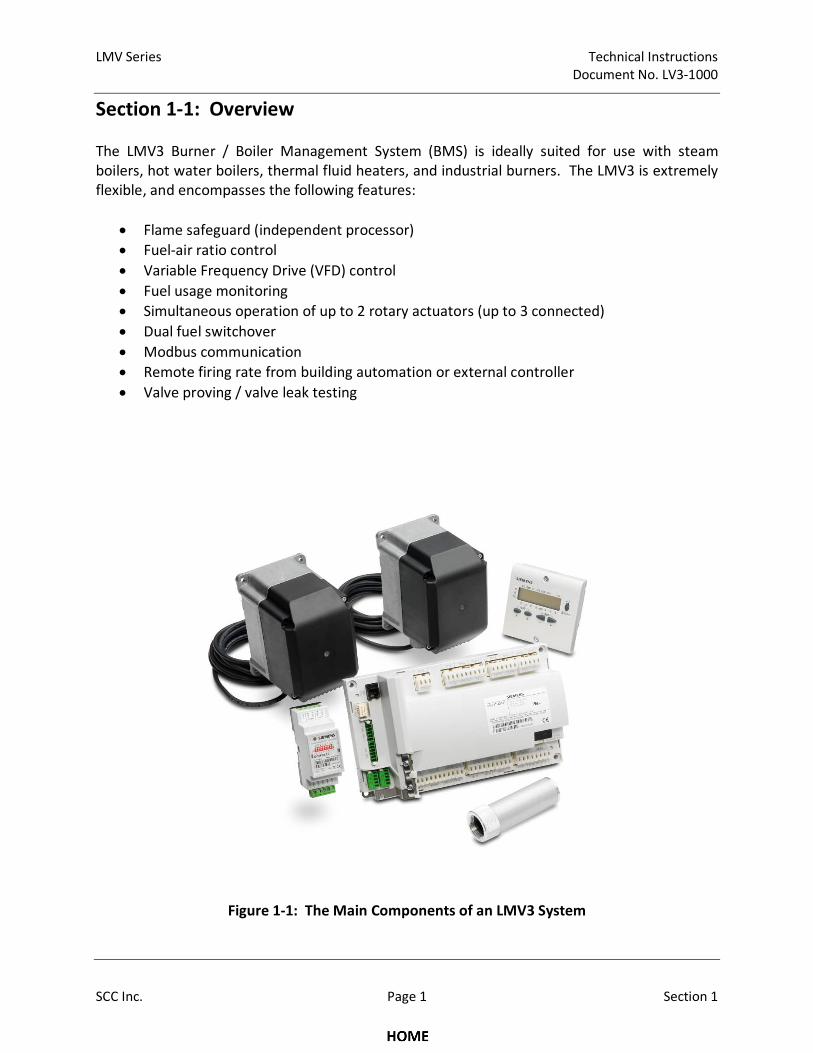
The LMV3 Burner / Boiler Management System (BMS) is ideally suited for use with steam
boilers, hot water boilers, thermal fluid heaters, and industrial burners. The LMV3 is extremely
flexible, and encompasses the following features:
• Flame safeguard (independent processor)
• Fuel-air ratio control
• Variable Frequency Drive (VFD) control
• Fuel usage monitoring
• Simultaneous operation of up to 2 rotary actuators (up to 3 connected)
• Dual fuel switchover
• Modbus communication
• Remote firing rate from building automation or external controller
• Valve proving / valve leak testing
Figure 1-1: The Main Components of an LMV3 System
Technical Instructions LMV Series
Document No. LV3-1000
Section 1 Page 2 SCC Inc.
Section 1-2: LMV3 System Builder
The LMV3 Linkageless Burner Management System is comprised of many components in
addition to the LMV3 itself. Use the following pages to choose the components needed for
your specific application. See pages 13 and 15 for an LMV3 system order sheet.
Control Panel Components
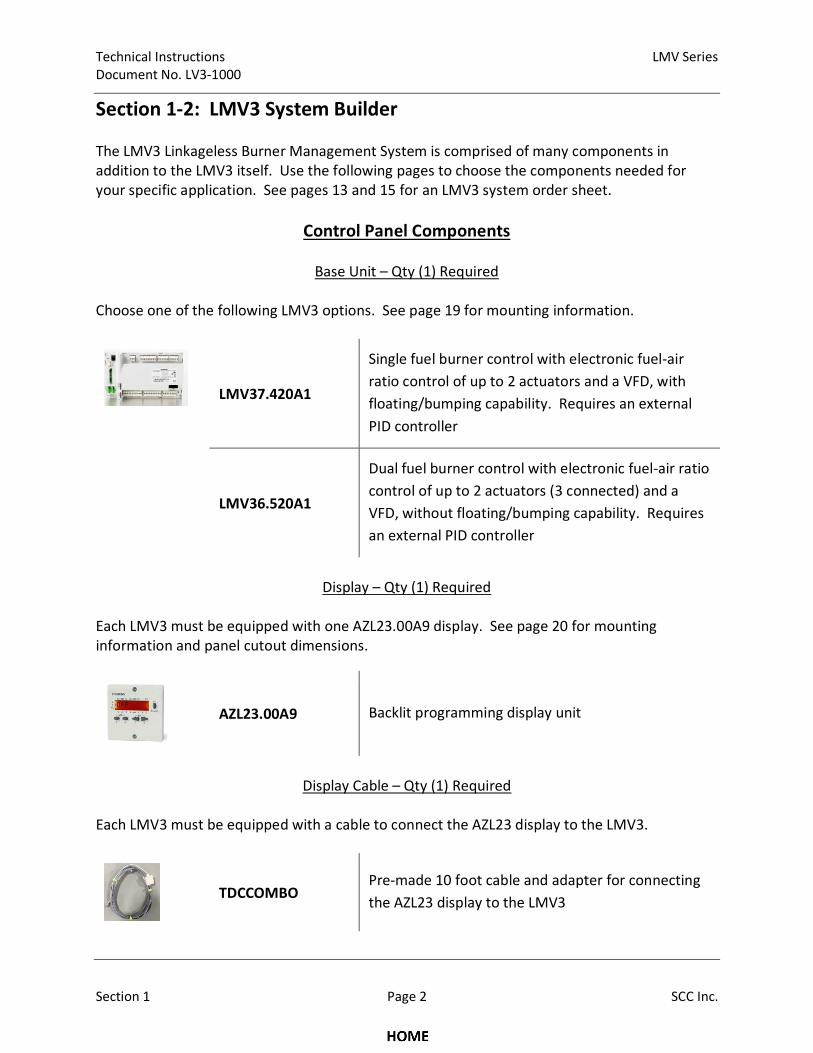
Base Unit – Qty (1) Required
Choose one of the following LMV3 options. See page 19 for mounting information.
LMV37.420A1
Single fuel burner control with electronic fuel-air
ratio control of up to 2 actuators and a VFD, with
floating/bumping capability. Requires an external
PID controller
LMV36.520A1
Dual fuel burner control with electronic fuel-air ratio
control of up to 2 actuators (3 connected) and a
VFD, without floating/bumping capability. Requires
an external PID controller
Display – Qty (1) Required
Each LMV3 must be equipped with one AZL23.00A9 display. See page 20 for mounting
information and panel cutout dimensions.
AZL23.00A9 Backlit programming display unit
Display Cable – Qty (1) Required
Each LMV3 must be equipped with a cable to connect the AZL23 display to the LMV3.
TDCCOMBO Pre-made 10 foot cable and adapter for connecting
the AZL23 display to the LMV3
LMV Series Technical Instructions
Document No. LV3-1000
SCC Inc. Page 3 Section 1
Control Panel Components (continued)
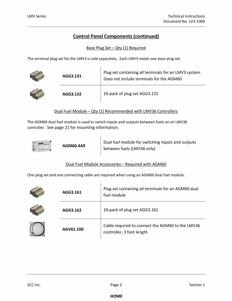
Base Plug Set – Qty (1) Required
The terminal plug set for the LMV3 is sold separately. Each LMV3 needs one base plug set.
AGG3.131
Plug set containing all terminals for an LMV3 system.
Does not include terminals for the AGM60
AGG3.132 10-pack of plug set AGG3.131
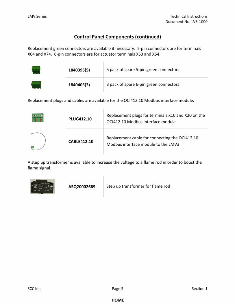
Dual Fuel Module – Qty (1) Recommended with LMV36 Controllers
The AGM60 dual fuel module is used to switch inputs and outputs between fuels on an LMV36
controller. See page 21 for mounting information.
AGM60.4A9 Dual fuel module for switching inputs and outputs
between fuels (LMV36 only)
Dual Fuel Module Accessories – Required with AGM60
One plug set and one connecting cable are required when using an AGM60 dual fuel module.
AGG3.161
Plug set containing all terminals for an AGM60 dual
fuel module
AGG3.162 10-pack of plug set AGG3.161
AGV61.100 Cable required to connect the AGM60 to the LMV36
controller, 3 foot length

Technical Instructions LMV Series
Document No. LV3-1000
Section 1 Page 4 SCC Inc.
Control Panel Components (continued)
Dual Fuel Module Accessories – Optional
The following accessories are optional when using an AGM60 dual fuel module.
AGG4.200 Mounting bracket to mount the AGM60 directly on
top of the LMV36 controller for a smaller footprint
Touchscreens – Optional
Touchscreen kits are available to provide a human machine interface for the LMV3. Kits come
with a touchscreen and a plate kit with all necessary inputs and outputs. Standard
communication is via Modbus TCP/IP. Other communication types are available. For more
technical information about touchscreens, refer to Document No. TS-1000.
TS… Touchscreen kits with 6” or 10” touchscreen, power
supply, interconnect terminals, and optional PLC
Modbus Interface Module – Optional
A separate interface module is required for Modbus communication with the LMV3. The cable
that connects the interface module to the LMV3 is provided with the module.
OCI412.10 Modbus interface module for the LMV3
Control Panel Spare Parts – Optional
The LMV3 has one replaceable main power fuse. Each LMV3 comes with a spare fuse.
Additional spare fuses are available if necessary.
FUSE6.3A-SLOW 5 pack of LMV3 primary fuses - 6.3A, 250V,
5x20mm, slow blow, for 120 VAC power
LMV Series Technical Instructions
Document No. LV3-1000
SCC Inc. Page 5 Section 1
Control Panel Components (continued)
Replacement green connectors are available if necessary. 5-pin connectors are for terminals
X64 and X74. 6-pin connectors are for actuator terminals X53 and X54.
1840395(5) 5 pack of spare 5-pin green connectors
1840405(3) 3 pack of spare 6-pin green connectors
Replacement plugs and cables are available for the OCI412.10 Modbus interface module.
PLUG412.10
Replacement plugs for terminals X10 and X20 on the
OCI412.10 Modbus interface module
CABLE412.10 Replacement cable for connecting the OCI412.10
Modbus interface module to the LMV3
A step up transformer is available to increase the voltage to a flame rod in order to boost the
flame signal.
A5Q20002669 Step up transformer for flame rod
Technical Instructions LMV Series
Document No. LV3-1000
Section 1 Page 6 SCC Inc.
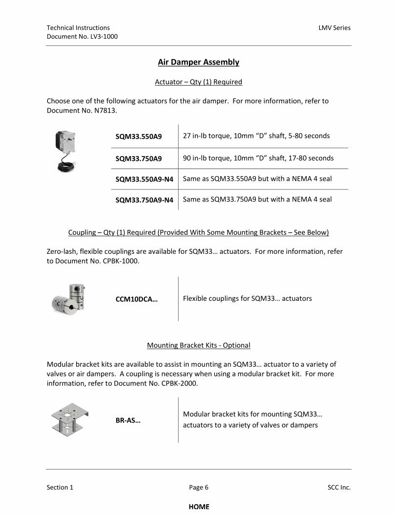
Air Damper Assembly
Actuator – Qty (1) Required
Choose one of the following actuators for the air damper. For more information, refer to
Document No. N7813.
SQM33.550A9 27 in-lb torque, 10mm “D” shaft, 5-80 seconds
SQM33.750A9 90 in-lb torque, 10mm “D” shaft, 17-80 seconds
SQM33.550A9-N4 Same as SQM33.550A9 but with a NEMA 4 seal
SQM33.750A9-N4 Same as SQM33.750A9 but with a NEMA 4 seal
Coupling – Qty (1) Required (Provided With Some Mounting Brackets – See Below)
Zero-lash, flexible couplings are available for SQM33… actuators. For more information, refer
to Document No. CPBK-1000.
CCM10DCA… Flexible couplings for SQM33… actuators
Mounting Bracket Kits - Optional
Modular bracket kits are available to assist in mounting an SQM33… actuator to a variety of
valves or air dampers. A coupling is necessary when using a modular bracket kit. For more
information, refer to Document No. CPBK-2000.
BR-AS… Modular bracket kits for mounting SQM33…
actuators to a variety of valves or dampers
LMV Series Technical Instructions
Document No. LV3-1000
SCC Inc. Page 7 Section 1
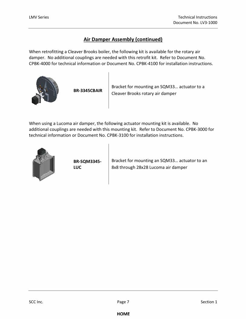
Air Damper Assembly (continued)
When retrofitting a Cleaver Brooks boiler, the following kit is available for the rotary air
damper. No additional couplings are needed with this retrofit kit. Refer to Document No.
CPBK-4000 for technical information or Document No. CPBK-4100 for installation instructions.
BR-3345CBAIR Bracket for mounting an SQM33… actuator to a
Cleaver Brooks rotary air damper
When using a Lucoma air damper, the following actuator mounting kit is available. No
additional couplings are needed with this mounting kit. Refer to Document No. CPBK-3000 for
technical information or Document No. CPBK-3100 for installation instructions.
BR-SQM3345-
LUC
Bracket for mounting an SQM33… actuator to an
8x8 through 28x28 Lucoma air damper
Technical Instructions LMV Series
Document No. LV3-1000
Section 1 Page 8 SCC Inc.
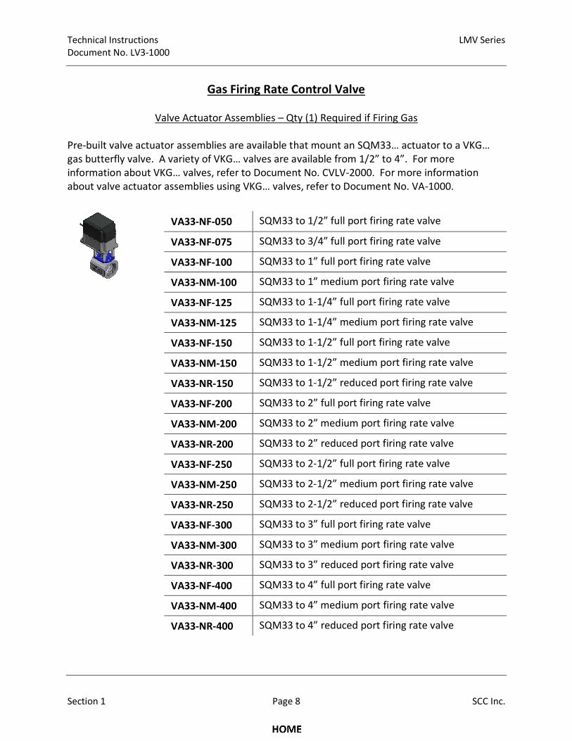
Gas Firing Rate Control Valve
Valve Actuator Assemblies – Qty (1) Required if Firing Gas
Pre-built valve actuator assemblies are available that mount an SQM33… actuator to a VKG…
gas butterfly valve. A variety of VKG… valves are available from 1/2” to 4”. For more
information about VKG… valves, refer to Document No. CVLV-2000. For more information
about valve actuator assemblies using VKG… valves, refer to Document No. VA-1000.
VA33-NF-050 SQM33 to 1/2” full port firing rate valve
VA33-NF-075 SQM33 to 3/4” full port firing rate valve
VA33-NF-100 SQM33 to 1” full port firing rate valve
VA33-NM-100 SQM33 to 1” medium port firing rate valve
VA33-NF-125 SQM33 to 1-1/4” full port firing rate valve
VA33-NM-125 SQM33 to 1-1/4” medium port firing rate valve
VA33-NF-150 SQM33 to 1-1/2” full port firing rate valve
VA33-NM-150 SQM33 to 1-1/2” medium port firing rate valve
VA33-NR-150 SQM33 to 1-1/2” reduced port firing rate valve
VA33-NF-200 SQM33 to 2” full port firing rate valve
VA33-NM-200 SQM33 to 2” medium port firing rate valve
VA33-NR-200 SQM33 to 2” reduced port firing rate valve
VA33-NF-250 SQM33 to 2-1/2” full port firing rate valve
VA33-NM-250 SQM33 to 2-1/2” medium port firing rate valve
VA33-NR-250 SQM33 to 2-1/2” reduced port firing rate valve
VA33-NF-300 SQM33 to 3” full port firing rate valve
VA33-NM-300 SQM33 to 3” medium port firing rate valve
VA33-NR-300 SQM33 to 3” reduced port firing rate valve
VA33-NF-400 SQM33 to 4” full port firing rate valve
VA33-NM-400 SQM33 to 4” medium port firing rate valve
VA33-NR-400 SQM33 to 4” reduced port firing rate valve
LMV Series Technical Instructions
Document No. LV3-1000
SCC Inc. Page 9 Section 1
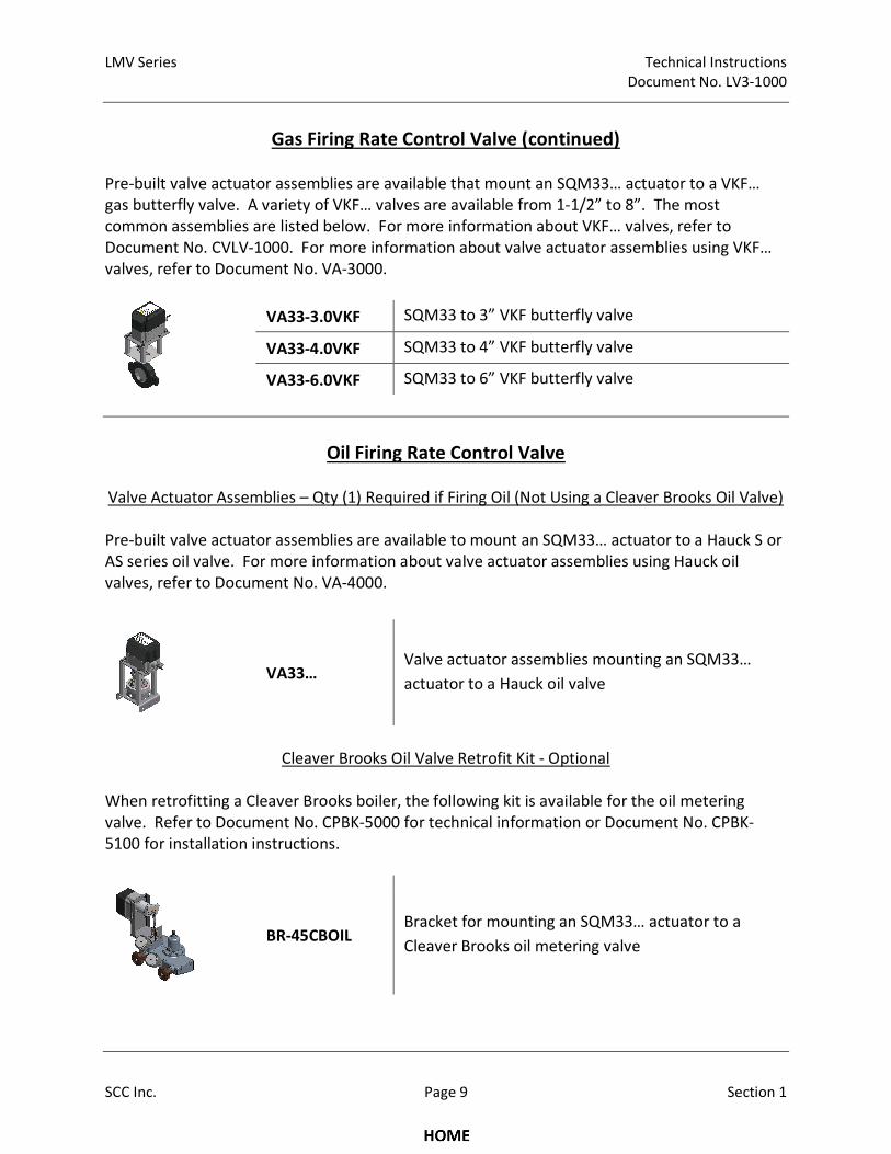
Gas Firing Rate Control Valve (continued)
Pre-built valve actuator assemblies are available that mount an SQM33… actuator to a VKF…
gas butterfly valve. A variety of VKF… valves are available from 1-1/2” to 8”. The most
common assemblies are listed below. For more information about VKF… valves, refer to
Document No. CVLV-1000. For more information about valve actuator assemblies using VKF…
valves, refer to Document No. VA-3000.
VA33-3.0VKF SQM33 to 3” VKF butterfly valve
VA33-4.0VKF SQM33 to 4” VKF butterfly valve
VA33-6.0VKF SQM33 to 6” VKF butterfly valve
Oil Firing Rate Control Valve
Valve Actuator Assemblies – Qty (1) Required if Firing Oil (Not Using a Cleaver Brooks Oil Valve)
Pre-built valve actuator assemblies are available to mount an SQM33… actuator to a Hauck S or
AS series oil valve. For more information about valve actuator assemblies using Hauck oil
valves, refer to Document No. VA-4000.
VA33… Valve actuator assemblies mounting an SQM33…
actuator to a Hauck oil valve
Cleaver Brooks Oil Valve Retrofit Kit - Optional
When retrofitting a Cleaver Brooks boiler, the following kit is available for the oil metering
valve. Refer to Document No. CPBK-5000 for technical information or Document No. CPBK-
5100 for installation instructions.
BR-45CBOIL Bracket for mounting an SQM33… actuator to a
Cleaver Brooks oil metering valve
Technical Instructions LMV Series
Document No. LV3-1000
Section 1 Page 10 SCC Inc.
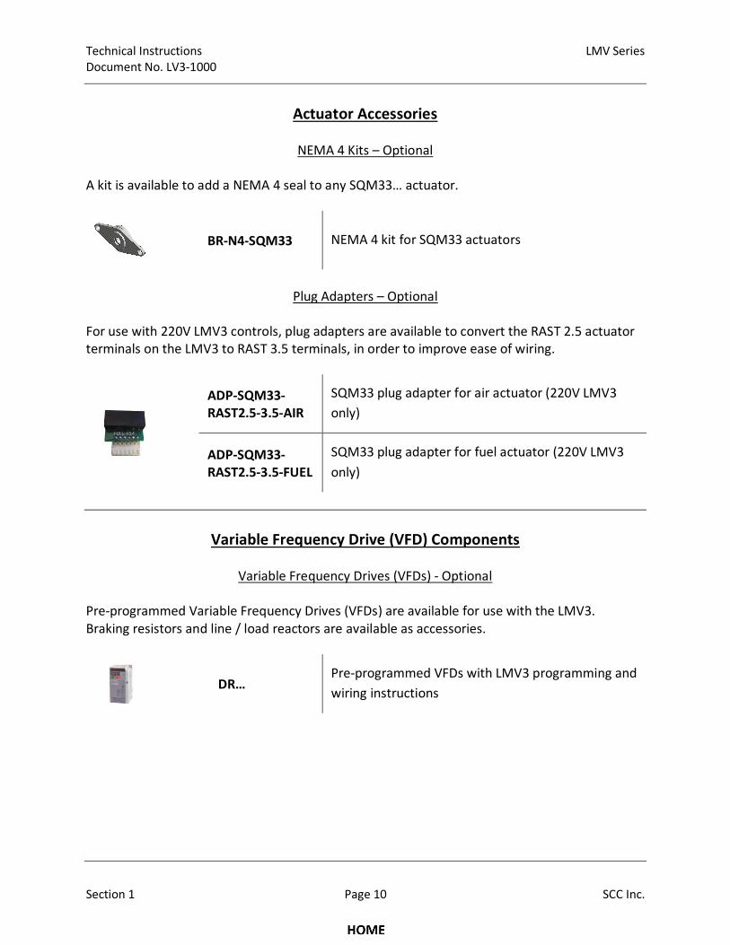
Actuator Accessories
NEMA 4 Kits – Optional
A kit is available to add a NEMA 4 seal to any SQM33… actuator.
BR-N4-SQM33 NEMA 4 kit for SQM33 actuators
Plug Adapters – Optional
For use with 220V LMV3 controls, plug adapters are available to convert the RAST 2.5 actuator
terminals on the LMV3 to RAST 3.5 terminals, in order to improve ease of wiring.
ADP-SQM33-
RAST2.5-3.5-AIR
SQM33 plug adapter for air actuator (220V LMV3
only)
ADP-SQM33-
RAST2.5-3.5-FUEL
SQM33 plug adapter for fuel actuator (220V LMV3
only)
Variable Frequency Drive (VFD) Components
Variable Frequency Drives (VFDs) - Optional
Pre-programmed Variable Frequency Drives (VFDs) are available for use with the LMV3.
Braking resistors and line / load reactors are available as accessories.
DR…
Pre-programmed VFDs with LMV3 programming and
wiring instructions
LMV Series Technical Instructions
Document No. LV3-1000
SCC Inc. Page 11 Section 1
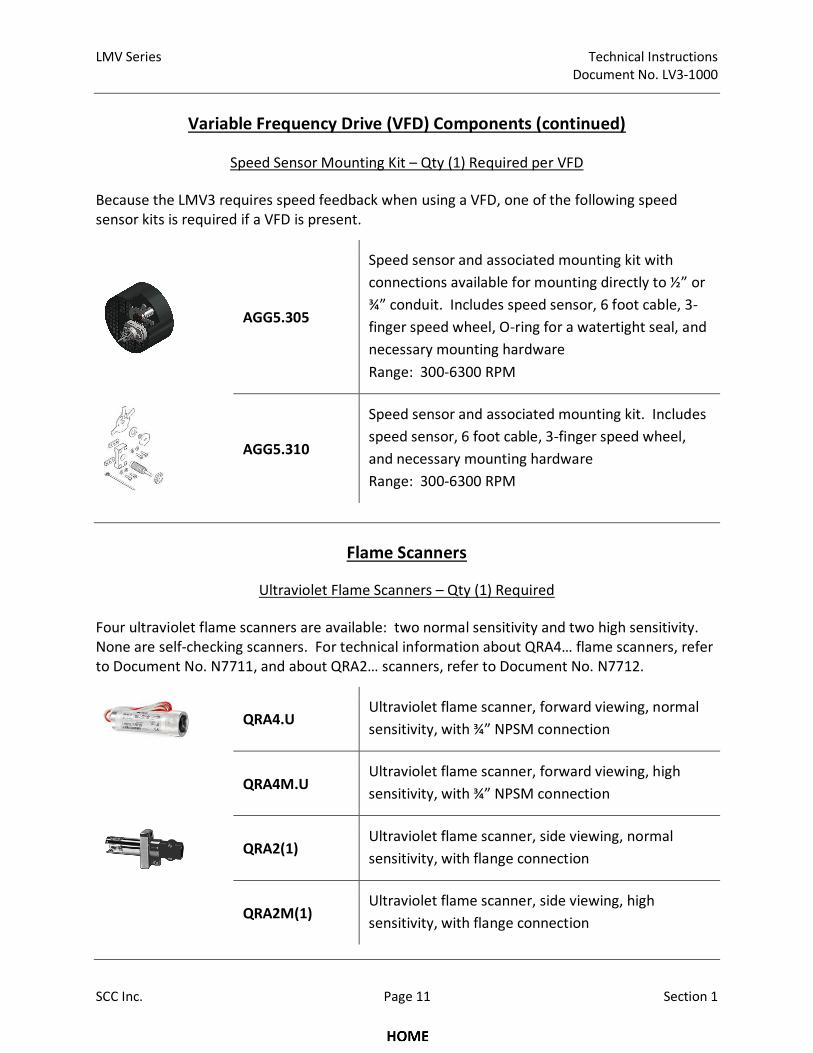
Variable Frequency Drive (VFD) Components (continued)
Speed Sensor Mounting Kit – Qty (1) Required per VFD
Because the LMV3 requires speed feedback when using a VFD, one of the following speed
sensor kits is required if a VFD is present.
AGG5.305
Speed sensor and associated mounting kit with
connections available for mounting directly to ½” or
¾” conduit. Includes speed sensor, 6 foot cable, 3-
finger speed wheel, O-ring for a watertight seal, and
necessary mounting hardware
Range: 300-6300 RPM
AGG5.310
Speed sensor and associated mounting kit. Includes
speed sensor, 6 foot cable, 3-finger speed wheel,
and necessary mounting hardware
Range: 300-6300 RPM
Flame Scanners
Ultraviolet Flame Scanners – Qty (1) Required
Four ultraviolet flame scanners are available: two normal sensitivity and two high sensitivity.
None are self-checking scanners. For technical information about QRA4… flame scanners, refer
to Document No. N7711, and about QRA2… scanners, refer to Document No. N7712.
QRA4.U Ultraviolet flame scanner, forward viewing, normal
sensitivity, with ¾” NPSM connection
QRA4M.U Ultraviolet flame scanner, forward viewing, high
sensitivity, with ¾” NPSM connection
QRA2(1)
Ultraviolet flame scanner, side viewing, normal
sensitivity, with flange connection
QRA2M(1) Ultraviolet flame scanner, side viewing, high
sensitivity, with flange connection
Technical Instructions LMV Series
Document No. LV3-1000
Section 1 Page 12 SCC Inc.
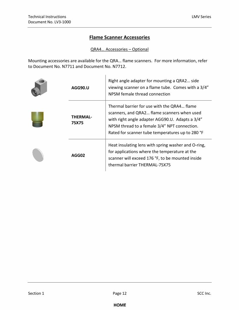
Flame Scanner Accessories
QRA4… Accessories – Optional
Mounting accessories are available for the QRA… flame scanners. For more information, refer
to Document No. N7711 and Document No. N7712.
AGG90.U
Right angle adapter for mounting a QRA2… side
viewing scanner on a flame tube. Comes with a 3/4”
NPSM female thread connection
THERMAL-
75X75
Thermal barrier for use with the QRA4… flame
scanners, and QRA2… flame scanners when used
with right angle adapter AGG90.U. Adapts a 3/4”
NPSM thread to a female 3/4” NPT connection.
Rated for scanner tube temperatures up to 280 °F
AGG02
Heat insulating lens with spring washer and O-ring,
for applications where the temperature at the
scanner will exceed 176 °F, to be mounted inside
thermal barrier THERMAL-75X75
LMV Series Technical Instructions
Document No. LV3-1000
SCC Inc. Page 13 Section 1
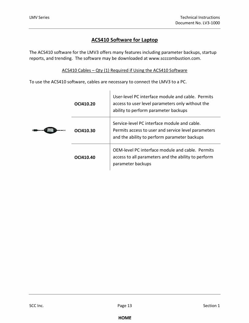
ACS410 Software for Laptop
The ACS410 software for the LMV3 offers many features including parameter backups, startup
reports, and trending. The software may be downloaded at www.scccombustion.com.
ACS410 Cables – Qty (1) Required if Using the ACS410 Software
To use the ACS410 software, cables are necessary to connect the LMV3 to a PC.
OCI410.20
User-level PC interface module and cable. Permits
access to user level parameters only without the
ability to perform parameter backups
OCI410.30
Service-level PC interface module and cable.
Permits access to user and service level parameters
and the ability to perform parameter backups
OCI410.40
OEM-level PC interface module and cable. Permits
access to all parameters and the ability to perform
parameter backups

Technical Instructions LMV Series
Document No. LV3-1000
Section 1 Page 14 SCC Inc.
Intentionally Left Blank
LMV Series Technical Instructions
Document No. LV3-1000
SCC Inc. Page 15 Section 1
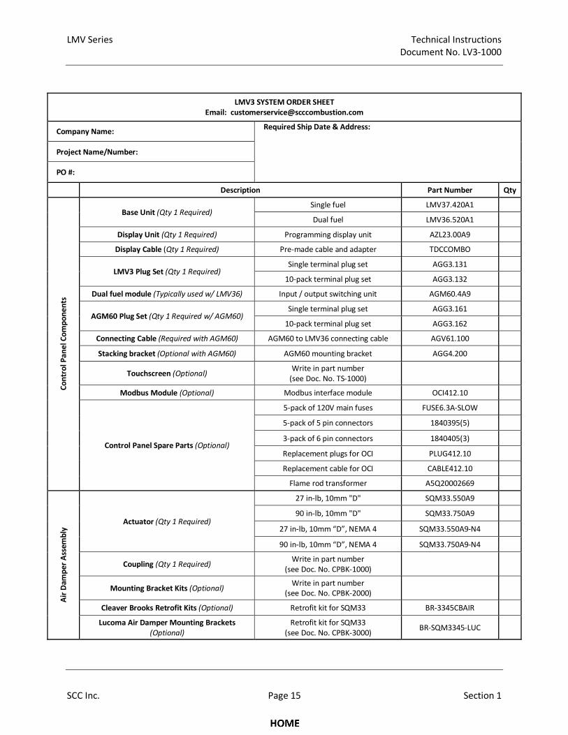
LMV3 SYSTEM ORDER SHEET
Email: [email protected]
Company Name: Required Ship Date & Address:
Project Name/Number:
PO #:
Description Part Number Qty
Co
ntr
ol
Pa
ne
l Co
mp
on
en
ts
Base Unit (Qty 1 Required) Single fuel LMV37.420A1
Dual fuel LMV36.520A1
Display Unit (Qty 1 Required) Programming display unit AZL23.00A9
Display Cable (Qty 1 Required) Pre-made cable and adapter TDCCOMBO
LMV3 Plug Set (Qty 1 Required) Single terminal plug set AGG3.131
10-pack terminal plug set AGG3.132
Dual fuel module (Typically used w/ LMV36) Input / output switching unit AGM60.4A9
AGM60 Plug Set (Qty 1 Required w/ AGM60) Single terminal plug set AGG3.161
10-pack terminal plug set AGG3.162
Connecting Cable (Required with AGM60) AGM60 to LMV36 connecting cable AGV61.100
Stacking bracket (Optional with AGM60) AGM60 mounting bracket AGG4.200
Touchscreen (Optional) Write in part number
(see Doc. No. TS-1000)
Modbus Module (Optional) Modbus interface module OCI412.10
Control Panel Spare Parts (Optional)
5-pack of 120V main fuses FUSE6.3A-SLOW
5-pack of 5 pin connectors 1840395(5)
3-pack of 6 pin connectors 1840405(3)
Replacement plugs for OCI PLUG412.10
Replacement cable for OCI CABLE412.10
Flame rod transformer A5Q20002669
Air
Da
mp
er
Ass
em
bly
Actuator (Qty 1 Required)
27 in-lb, 10mm "D" SQM33.550A9
90 in-lb, 10mm "D" SQM33.750A9
27 in-lb, 10mm “D”, NEMA 4 SQM33.550A9-N4
90 in-lb, 10mm “D”, NEMA 4 SQM33.750A9-N4
Coupling (Qty 1 Required) Write in part number
(see Doc. No. CPBK-1000)
Mounting Bracket Kits (Optional) Write in part number
(see Doc. No. CPBK-2000)
Cleaver Brooks Retrofit Kits (Optional) Retrofit kit for SQM33 BR-3345CBAIR
Lucoma Air Damper Mounting Brackets
(Optional)
Retrofit kit for SQM33
(see Doc. No. CPBK-3000) BR-SQM3345-LUC

Technical Instructions LMV Series
Document No. LV3-1000
Section 1 Page 16 SCC Inc.
Intentionally Left Blank
LMV Series Technical Instructions
Document No. LV3-1000
SCC Inc. Page 17 Section 1
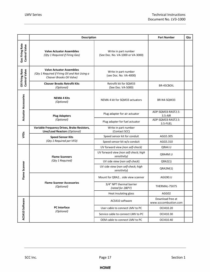
Description Part Number Qty
Ga
s Fi
rin
g R
ate
Co
ntr
ol V
alv
e
Valve Actuator Assemblies
(Qty 1 Required if Firing Gas)
Write in part number
(See Doc. No. VA-1000 or VA-3000)
Oil
Fir
ing
Ra
te
Co
ntr
ol V
alv
e
Valve Actuator Assemblies
(Qty 1 Required if Firing Oil and Not Using a
Cleaver Brooks Oil Valve)
Write in part number
(see Doc. No. VA-4000)
Cleaver Brooks Retrofit Kits
(Optional)
Retrofit kit for SQM33
(See Doc. VA-5000) BR-45CBOIL
Act
ua
tor
Acc
ess
ori
es
NEMA 4 Kits
(Optional) NEMA 4 kit for SQM33 actuators BR-N4-SQM33
Plug Adapters
(Optional)
Plug adapter for air actuator ADP-SQM33-RAST2.5-
3.5-AIR
Plug adapter for fuel actuator ADP-SQM33-RAST2.5-
3.5-FUEL
VFD
s
Variable Frequency Drives, Brake Resistors,
Line/Load Reactors (Optional)
Write in part number
(Contact SCC)
Speed Sensor Kits
(Qty 1 Required per VFD)
Speed sensor kit for conduit AGG5.305
Speed sensor kit w/o conduit AGG5.310
Fla
me
Sca
nn
er
Flame Scanners
(Qty 1 Required)
UV forward view (non self-check) QRA4.U
UV forward view (non self-check; high
sensitivity) QRA4M.U
UV side view (non self-check) QRA2(1)
UV side view (non self-check; high
sensitivity) QRA2M(1)
Flame Scanner Accessories
(Optional)
Mount for QRA2… side view scanner AGG90.U
3/4" NPT thermal barrier
(rated for 280°F) THERMAL-75X75
Heat insulating glass AGG02
AC
S4
10
So
ftw
are
PC Interface
(Optional)
ACS410 software Download free at
www.scccombustion.com
User cable to connect LMV to PC OCI410.20
Service cable to connect LMV to PC OCI410.30
OEM cable to connect LMV to PC OCI410.40

Technical Instructions LMV Series
Document No. LV3-1000
Section 1 Page 18 SCC Inc.
Intentionally Left Blank
LMV Series Technical Instructions
Document No. LV3-1000
SCC Inc. Page 19 Section 1
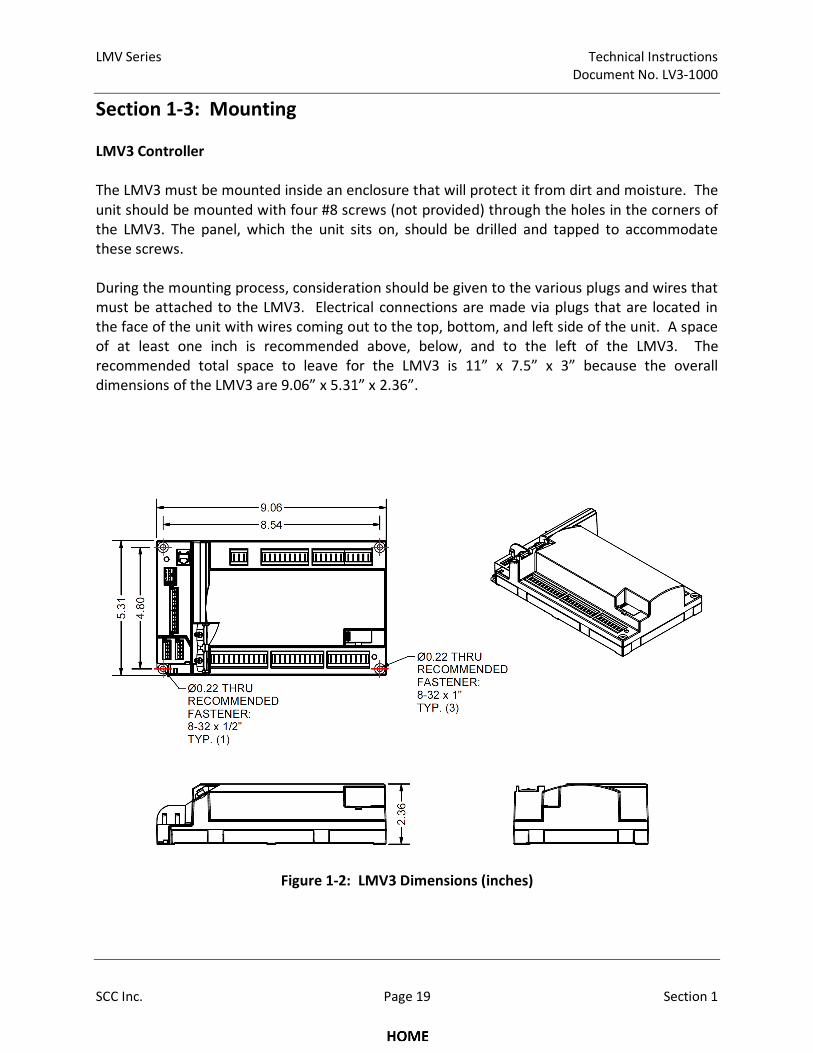
Section 1-3: Mounting
LMV3 Controller
The LMV3 must be mounted inside an enclosure that will protect it from dirt and moisture. The
unit should be mounted with four #8 screws (not provided) through the holes in the corners of
the LMV3. The panel, which the unit sits on, should be drilled and tapped to accommodate
these screws.
During the mounting process, consideration should be given to the various plugs and wires that
must be attached to the LMV3. Electrical connections are made via plugs that are located in
the face of the unit with wires coming out to the top, bottom, and left side of the unit. A space
of at least one inch is recommended above, below, and to the left of the LMV3. The
recommended total space to leave for the LMV3 is 11” x 7.5” x 3” because the overall
dimensions of the LMV3 are 9.06” x 5.31” x 2.36”.
Figure 1-2: LMV3 Dimensions (inches)
Technical Instructions LMV Series
Document No. LV3-1000
Section 1 Page 20 SCC Inc.
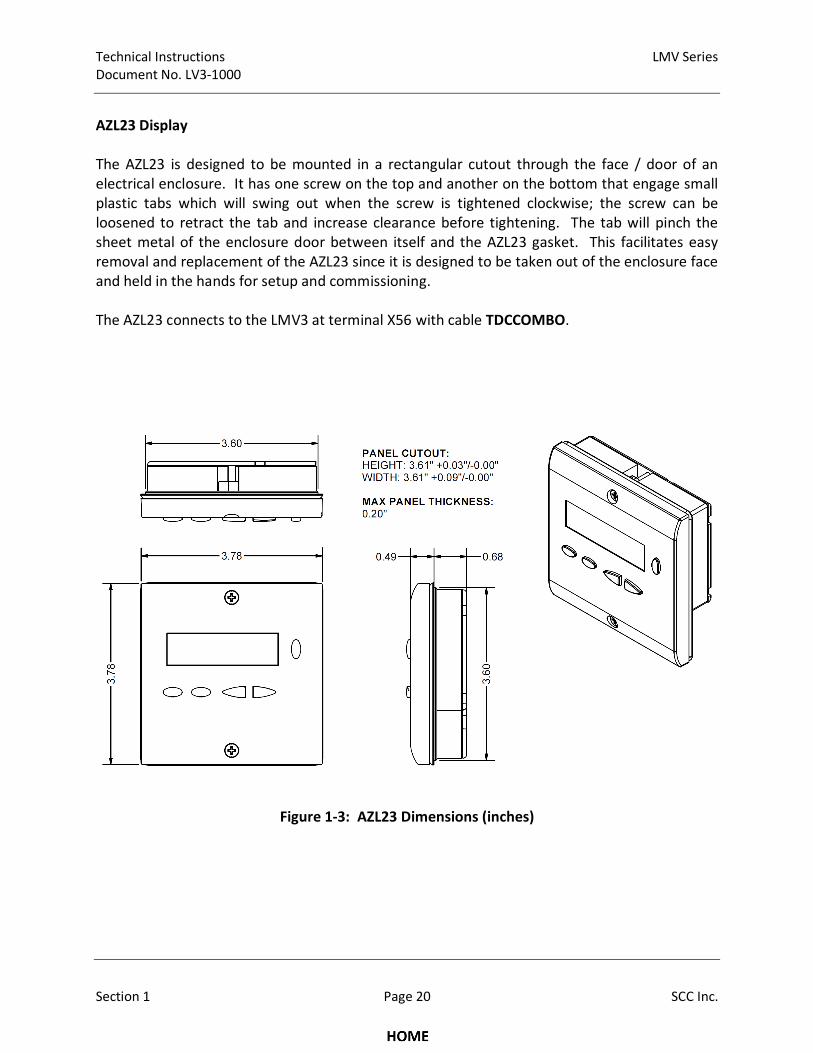
AZL23 Display
The AZL23 is designed to be mounted in a rectangular cutout through the face / door of an
electrical enclosure. It has one screw on the top and another on the bottom that engage small
plastic tabs which will swing out when the screw is tightened clockwise; the screw can be
loosened to retract the tab and increase clearance before tightening. The tab will pinch the
sheet metal of the enclosure door between itself and the AZL23 gasket. This facilitates easy
removal and replacement of the AZL23 since it is designed to be taken out of the enclosure face
and held in the hands for setup and commissioning.
The AZL23 connects to the LMV3 at terminal X56 with cable TDCCOMBO.
Figure 1-3: AZL23 Dimensions (inches)
LMV Series Technical Instructions
Document No. LV3-1000
SCC Inc. Page 21 Section 1
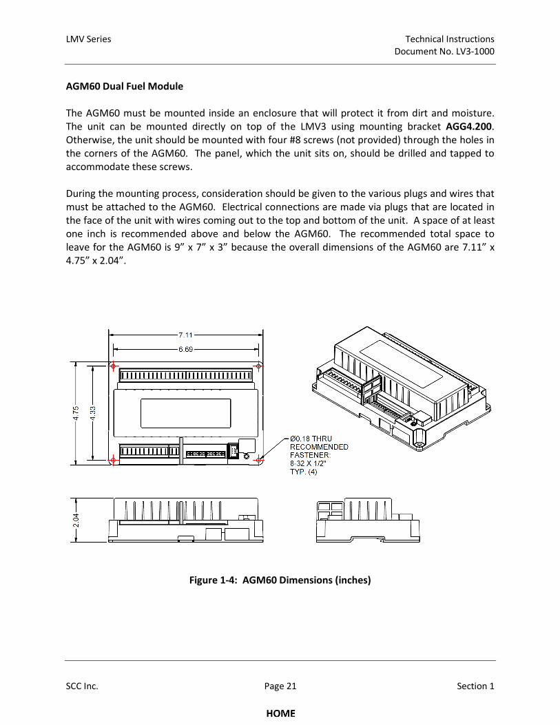
AGM60 Dual Fuel Module
The AGM60 must be mounted inside an enclosure that will protect it from dirt and moisture.
The unit can be mounted directly on top of the LMV3 using mounting bracket AGG4.200.
Otherwise, the unit should be mounted with four #8 screws (not provided) through the holes in
the corners of the AGM60. The panel, which the unit sits on, should be drilled and tapped to
accommodate these screws.
During the mounting process, consideration should be given to the various plugs and wires that
must be attached to the AGM60. Electrical connections are made via plugs that are located in
the face of the unit with wires coming out to the top and bottom of the unit. A space of at least
one inch is recommended above and below the AGM60. The recommended total space to
leave for the AGM60 is 9” x 7” x 3” because the overall dimensions of the AGM60 are 7.11” x
4.75” x 2.04”.
Figure 1-4: AGM60 Dimensions (inches)
Technical Instructions LMV Series
Document No. LV3-1000
Section 1 Page 22 SCC Inc.
Section 1-4: Important Safety Notes
• The LMV3 is a safety device. Under no circumstances should the unit be modified or
opened. SCC Inc. will not assume responsibility for damage resulting from unauthorized
modification of the unit.
• After commissioning, and after each service visit, the flue gas values should be checked
across the firing range.
• All activities (mounting, installation, service work, etc.) must be performed by qualified
staff.
• Before performing any work in the connection area of the LMV3, disconnect the unit
from the main supply (all-polar disconnection).
• Protection against electrical shock hazard on the LMV3 and all other connected
electrical components must be ensured through good wiring and grounding practices.
• Fall or shock can adversely affect the safety functions of an LMV3. Such units must not
be put into operation, even if they do not exhibit any apparent damage.
• The coupling that is used between the actuator and the driven valve / damper is safety
related, and must be of a robust and flexible design. Should this coupling fail during
operation, the LMV3 will no longer have control of the burner’s combustion, bringing
about a hazardous condition.
• Condensation and the entry of water into the unit must be avoided.
LMV Series Technical Instructions
Document No. LV3-1000
SCC Inc. Page 23 Section 1
Section 1-5: Approvals
The LMV3 has the following standards and approvals:

Technical Instructions LMV Series
Document No. LV3-1000
Section 1 Page 24 SCC Inc.
Intentionally Left Blank
Section 1 Overview
Section 2 Wiring
Section 3 Parameters
Section 4 Commissioning
Section 5 VSD
Section 6 Troubleshooting
Section 7 Modbus
Section 8 ACS410
Appendix A Application Guide

Section 1 Overview
Section 2 Wiring
Section 3 Parameters
Section 4 Commissioning
Section 5 VSD
Section 6 Troubleshooting
Section 7 Modbus
Section 8 ACS410
Appendix A Application Guide
LMV Series Technical Instructions Document No. LV3‐1000
SCC Inc. Page 1 Section 2
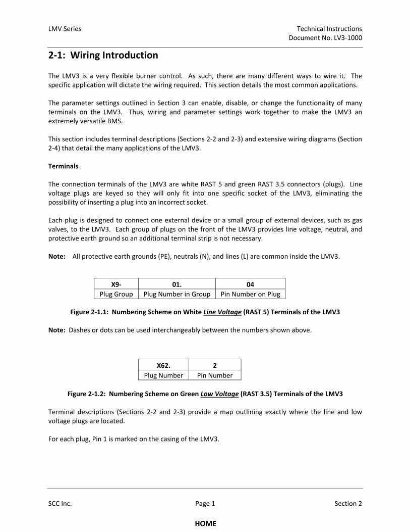
2‐1: Wiring Introduction The LMV3 is a very flexible burner control. As such, there are many different ways to wire it. The specific application will dictate the wiring required. This section details the most common applications. The parameter settings outlined in Section 3 can enable, disable, or change the functionality of many terminals on the LMV3. Thus, wiring and parameter settings work together to make the LMV3 an extremely versatile BMS. This section includes terminal descriptions (Sections 2‐2 and 2‐3) and extensive wiring diagrams (Section 2‐4) that detail the many applications of the LMV3. Terminals The connection terminals of the LMV3 are white RAST 5 and green RAST 3.5 connectors (plugs). Line voltage plugs are keyed so they will only fit into one specific socket of the LMV3, eliminating the possibility of inserting a plug into an incorrect socket. Each plug is designed to connect one external device or a small group of external devices, such as gas valves, to the LMV3. Each group of plugs on the front of the LMV3 provides line voltage, neutral, and protective earth ground so an additional terminal strip is not necessary. Note: All protective earth grounds (PE), neutrals (N), and lines (L) are common inside the LMV3.
X9‐ 01. 04
Plug Group Plug Number in Group Pin Number on Plug
Figure 2‐1.1: Numbering Scheme on White Line Voltage (RAST 5) Terminals of the LMV3 Note: Dashes or dots can be used interchangeably between the numbers shown above.
X62. 2
Plug Number Pin Number
Figure 2‐1.2: Numbering Scheme on Green Low Voltage (RAST 3.5) Terminals of the LMV3
Terminal descriptions (Sections 2‐2 and 2‐3) provide a map outlining exactly where the line and low voltage plugs are located. For each plug, Pin 1 is marked on the casing of the LMV3.
Technical Instructions LMV Series Document No. LV3‐1000
Section 2 Page 2 SCC Inc.
Grounds The LMV3 has two different types of grounds:
Protective Earth (PE)
Reference Ground (GND) Protective Earth Protective Earth (PE) or chassis ground must always be connected to the control panel grounding lug. The purpose of PE is to provide a ground for all 120 VAC connections. One wire from the secondary side of the control panel’s main step‐down transformer should also be connected to the control panel grounding lug. All of the PE terminals on the LMV3 are common. Reference Ground The other type of ground is the Reference Ground (GND). These are found on the low voltage connections. The purpose of GND is to serve as a reference point to measure other voltages.
LMV Series Technical Instructions Document No. LV3‐1000
SCC Inc. Page 3 Section 2
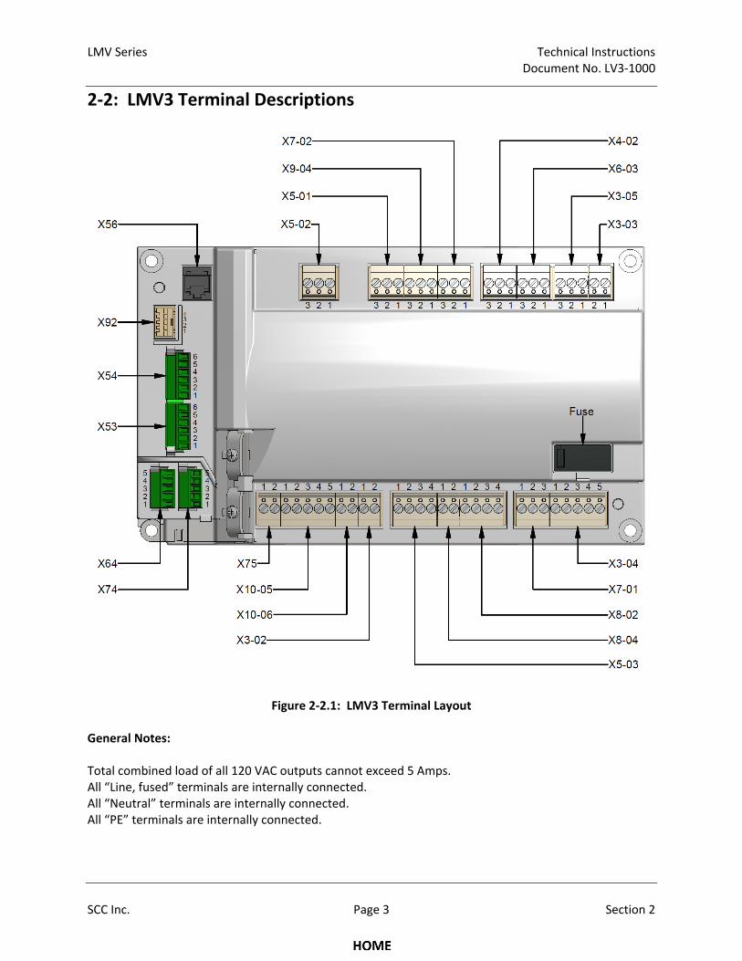
2‐2: LMV3 Terminal Descriptions
Figure 2‐2.1: LMV3 Terminal Layout General Notes: Total combined load of all 120 VAC outputs cannot exceed 5 Amps. All “Line, fused” terminals are internally connected. All “Neutral” terminals are internally connected. All “PE” terminals are internally connected.
Technical Instructions LMV Series Document No. LV3‐1000
Section 2 Page 4 SCC Inc.
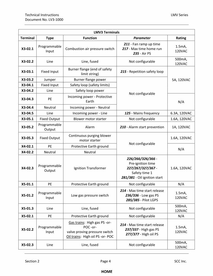
LMV3 Terminals
Terminal Type Function Parameter Rating
X3‐02.1 Programmable
Input Combustion air pressure switch
211 ‐ Fan ramp up time 217 ‐ Max time home run
235 ‐ Air PS
1.5mA, 120VAC
X3‐02.2 Line Line, fused Not configurable 500mA, 120VAC
X3‐03.1 Fixed Input Burner flange (end of safety
limit string) 215 ‐ Repetition safety loop
5A, 120VAC X3‐03.2 Jumper Burner flange power
Not configurable
X3‐04.1 Fixed Input Safety loop (safety limits)
X3‐04.2 Line Safety loop power
X3‐04.3 PE Incoming power ‐ Protective
Earth N/A
X3‐04.4 Neutral Incoming power ‐ Neutral
X3‐04.5 Line Incoming power ‐ Line 125 ‐ Mains frequency 6.3A, 120VAC
X3‐05.1 Fixed Output Blower motor starter Not configurable 1.6A, 120VAC
X3‐05.2 Programmable
Output Alarm 210 ‐ Alarm start prevention 1A, 120VAC
X3‐05.3 Fixed Output Continuous purging blower
motor starter Not configurable
1.6A, 120VAC
X4‐02.1 PE Protective Earth ground N/A
X4‐02.2 Neutral Neutral
X4‐02.3 Programmable
Output Ignition Transformer
226/266/326/366 ‐ Pre‐ignition time
227/267/327/367 ‐ Safety time 1
281/381 ‐ Oil ignition start
1.6A, 120VAC
X5‐01.1 PE Protective Earth ground Not configurable N/A
X5‐01.2 Programmable
Input Low gas pressure switch
214 ‐ Max time start release 236/336 ‐ Low gas PS 285/385 ‐ Pilot LGPS
1.5mA, 120VAC
X5‐01.3 Line Line, fused Not configurable 500mA, 120VAC
X5‐02.1 PE Protective Earth ground Not configurable N/A
X5‐02.2 Programmable
Input
Gas trains: High gas PS ‐or‐ POC ‐or‐
valve proving pressure switch Oil trains: High oil PS ‐or‐ POC
214 ‐ Max time start release 237/337 ‐ High gas PS 277/377 ‐ High oil PS
1.5mA, 120VAC
X5‐02.3 Line Line, fused Not configurable 500mA, 120VAC
LMV Series Technical Instructions Document No. LV3‐1000
SCC Inc. Page 5 Section 2
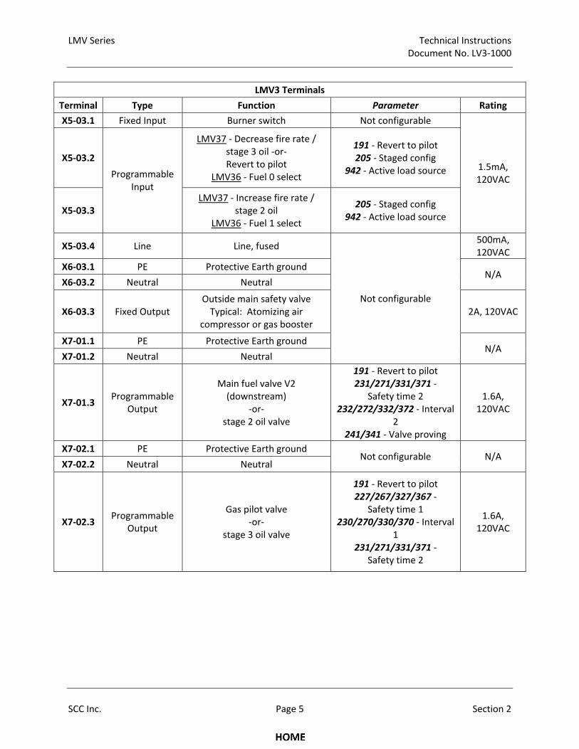
LMV3 Terminals
Terminal Type Function Parameter Rating
X5‐03.1 Fixed Input Burner switch Not configurable
1.5mA, 120VAC
X5‐03.2
Programmable Input
LMV37 ‐ Decrease fire rate / stage 3 oil ‐or‐ Revert to pilot
LMV36 ‐ Fuel 0 select
191 ‐ Revert to pilot 205 ‐ Staged config
942 ‐ Active load source
X5‐03.3 LMV37 ‐ Increase fire rate /
stage 2 oil LMV36 ‐ Fuel 1 select
205 ‐ Staged config 942 ‐ Active load source
X5‐03.4 Line Line, fused
Not configurable
500mA, 120VAC
X6‐03.1 PE Protective Earth ground N/A
X6‐03.2 Neutral Neutral
X6‐03.3 Fixed Output Outside main safety valve Typical: Atomizing air
compressor or gas booster 2A, 120VAC
X7‐01.1 PE Protective Earth ground N/A
X7‐01.2 Neutral Neutral
X7‐01.3 Programmable
Output
Main fuel valve V2 (downstream)
‐or‐ stage 2 oil valve
191 ‐ Revert to pilot 231/271/331/371 ‐
Safety time 2 232/272/332/372 ‐ Interval
2 241/341 ‐ Valve proving
1.6A, 120VAC
X7‐02.1 PE Protective Earth ground Not configurable N/A
X7‐02.2 Neutral Neutral
X7‐02.3 Programmable
Output
Gas pilot valve ‐or‐
stage 3 oil valve
191 ‐ Revert to pilot 227/267/327/367 ‐
Safety time 1 230/270/330/370 ‐ Interval
1 231/271/331/371 ‐
Safety time 2
1.6A, 120VAC
Technical Instructions LMV Series Document No. LV3‐1000
Section 2 Page 6 SCC Inc.
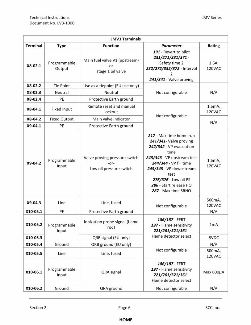
LMV3 Terminals
Terminal Type Function Parameter Rating
X8‐02.1 Programmable
Output
Main fuel valve V1 (upstream) ‐or‐
stage 1 oil valve
191 ‐ Revert to pilot 231/271/331/371 ‐
Safety time 2 232/272/332/372 ‐ Interval
2 241/341 ‐ Valve proving
1.6A, 120VAC
X8‐02.2 Tie Point Use as a tiepoint (EU use only)
Not configurable N/A X8‐02.3 Neutral Neutral
X8‐02.4 PE Protective Earth ground
X8‐04.1 Fixed Input Remote reset and manual
lockout Not configurable
1.5mA, 120VAC
X8‐04.2 Fixed Output Main valve indicator N/A
X9‐04.1 PE Protective Earth ground
X9‐04.2 Programmable
Input
Valve proving pressure switch ‐or‐
Low oil pressure switch
217 ‐ Max time home run 241/341‐ Valve proving 242/342 ‐ VP evacuation
time 243/343 ‐ VP upstream test
244/344 ‐ VP fill time 245/345 ‐ VP downstream
test 276/376 ‐ Low oil PS 286 ‐ Start release HO 287 ‐ Max time SRHO
1.5mA, 120VAC
X9‐04.3 Line Line, fused Not configurable
500mA, 120VAC
X10‐05.1 PE Protective Earth ground N/A
X10‐05.2 Programmable Input
Ionization probe signal (flame rod)
186/187 ‐ FFRT 197 ‐ Flame sensitivity 221/261/321/361 ‐ Flame detector select
1mA
X10‐05.3 QRB signal (EU only) 8VDC
X10‐05.4 Ground QRB ground (EU only) Not configurable
N/A
X10‐05.5 Line Line, fused 500mA, 120VAC
X10‐06.1 Programmable
Input QRA signal
186/187 ‐ FFRT 197 ‐ Flame sensitivity 221/261/321/361 ‐ Flame detector select
Max 600µA
X10‐06.2 Ground QRA ground Not configurable N/A
LMV Series Technical Instructions Document No. LV3‐1000
SCC Inc. Page 7 Section 2
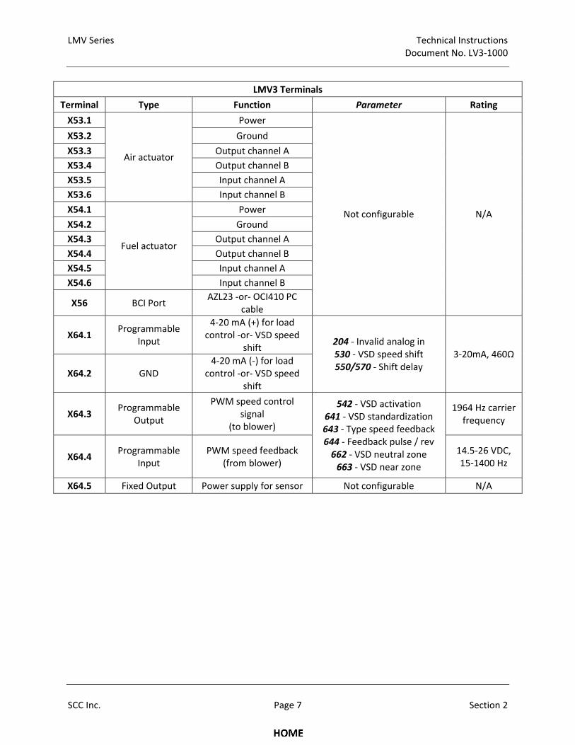
LMV3 Terminals
Terminal Type Function Parameter Rating
X53.1
Air actuator
Power
Not configurable N/A
X53.2 Ground
X53.3 Output channel A
X53.4 Output channel B
X53.5 Input channel A
X53.6 Input channel B
X54.1
Fuel actuator
Power
X54.2 Ground
X54.3 Output channel A
X54.4 Output channel B
X54.5 Input channel A
X54.6 Input channel B
X56 BCI Port AZL23 ‐or‐ OCI410 PC
cable
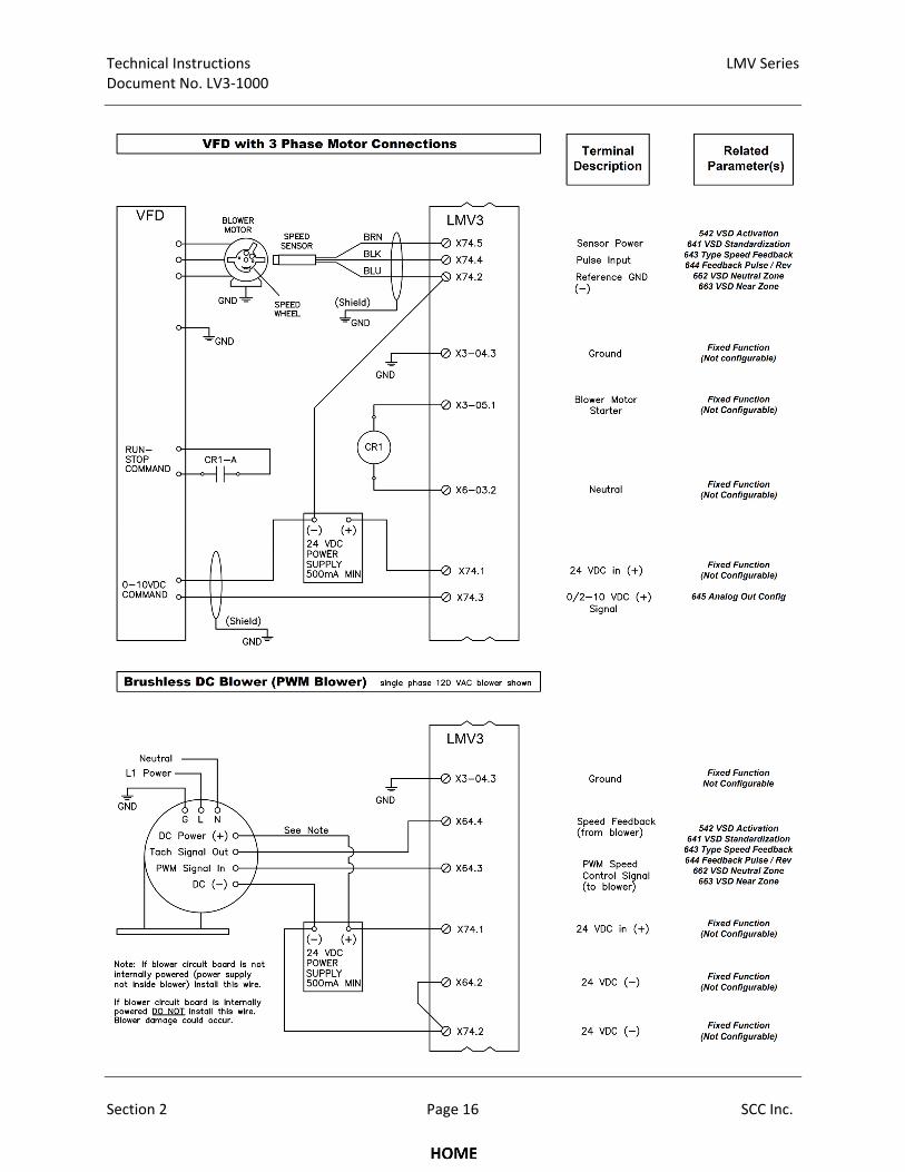
X64.1 Programmable
Input
4‐20 mA (+) for load control ‐or‐ VSD speed
shift 204 ‐ Invalid analog in 530 ‐ VSD speed shift 550/570 ‐ Shift delay
3‐20mA, 460Ω
X64.2 GND 4‐20 mA (‐) for load
control ‐or‐ VSD speed shift
X64.3 Programmable
Output
PWM speed control signal
(to blower)
542 ‐ VSD activation 641 ‐ VSD standardization 643 ‐ Type speed feedback 644 ‐ Feedback pulse / rev 662 ‐ VSD neutral zone 663 ‐ VSD near zone
1964 Hz carrier frequency
X64.4 Programmable
Input PWM speed feedback
(from blower) 14.5‐26 VDC, 15‐1400 Hz
X64.5 Fixed Output Power supply for sensor Not configurable N/A
Technical Instructions LMV Series Document No. LV3‐1000
Section 2 Page 8 SCC Inc.
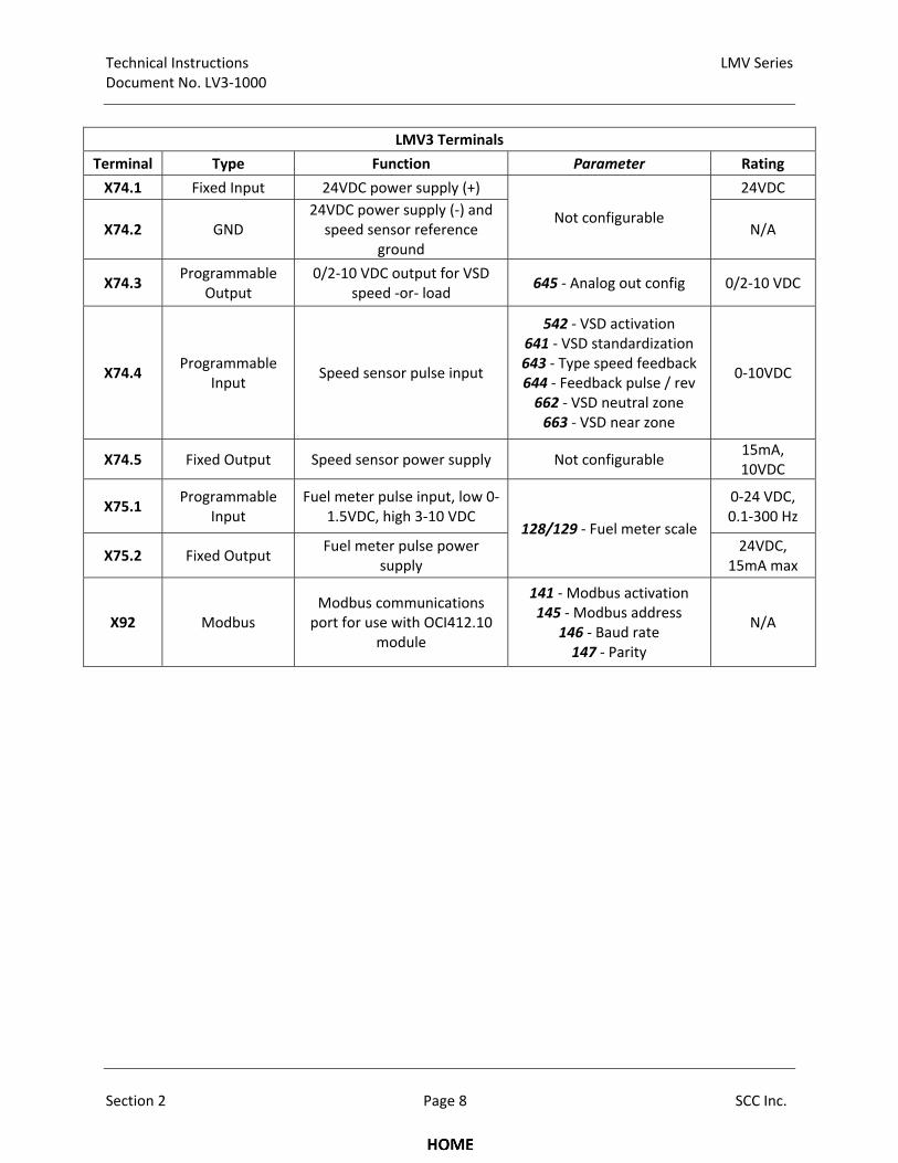
LMV3 Terminals
Terminal Type Function Parameter Rating
X74.1 Fixed Input 24VDC power supply (+)
Not configurable
24VDC
X74.2 GND 24VDC power supply (‐) and speed sensor reference
ground N/A
X74.3 Programmable
Output 0/2‐10 VDC output for VSD
speed ‐or‐ load 645 ‐ Analog out config 0/2‐10 VDC
X74.4 Programmable
Input Speed sensor pulse input
542 ‐ VSD activation 641 ‐ VSD standardization 643 ‐ Type speed feedback 644 ‐ Feedback pulse / rev 662 ‐ VSD neutral zone 663 ‐ VSD near zone
0‐10VDC
X74.5 Fixed Output Speed sensor power supply Not configurable 15mA, 10VDC
X75.1 Programmable
Input Fuel meter pulse input, low 0‐
1.5VDC, high 3‐10 VDC 128/129 ‐ Fuel meter scale
0‐24 VDC, 0.1‐300 Hz
X75.2 Fixed Output Fuel meter pulse power
supply 24VDC,
15mA max
X92 Modbus Modbus communications port for use with OCI412.10
module
141 ‐ Modbus activation 145 ‐ Modbus address
146 ‐ Baud rate 147 ‐ Parity
N/A
LMV Series Technical Instructions Document No. LV3‐1000
SCC Inc. Page 9 Section 2
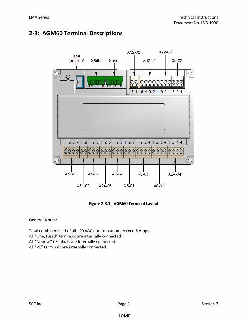
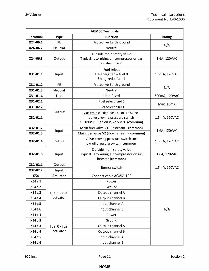
2‐3: AGM60 Terminal Descriptions
Figure 2‐3.1: AGM60 Terminal Layout
General Notes: Total combined load of all 120 VAC outputs cannot exceed 5 Amps. All “Line, fused” terminals are internally connected. All “Neutral” terminals are internally connected. All “PE” terminals are internally connected.
Technical Instructions LMV Series Document No. LV3‐1000
Section 2 Page 10 SCC Inc.
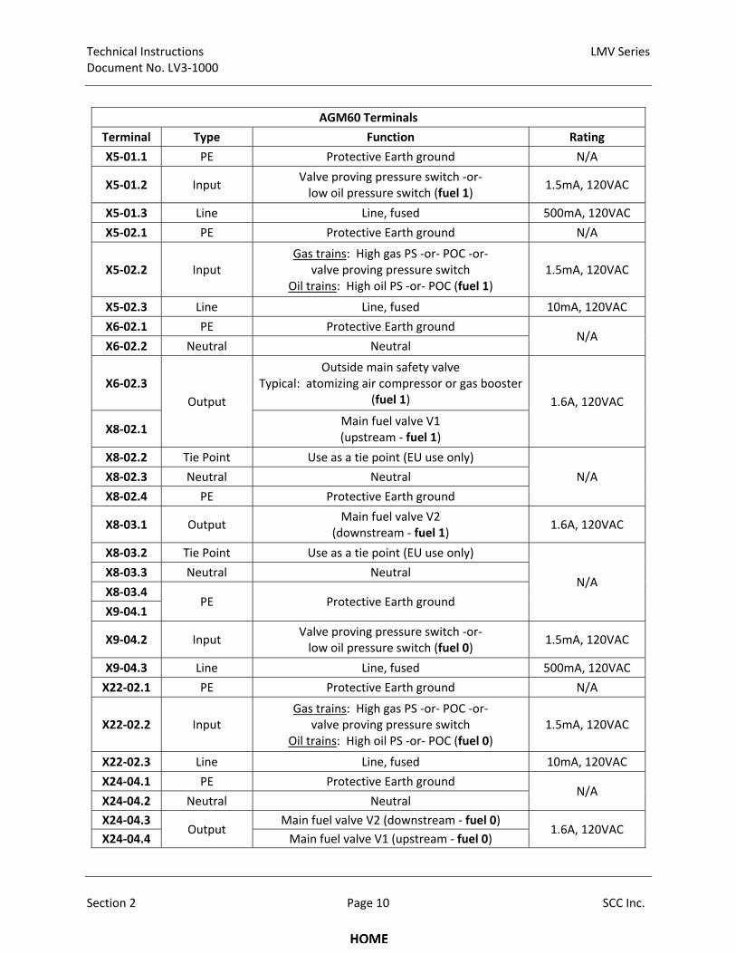
AGM60 Terminals
Terminal Type Function Rating
X5‐01.1 PE Protective Earth ground N/A
X5‐01.2 Input Valve proving pressure switch ‐or‐ low oil pressure switch (fuel 1)
1.5mA, 120VAC
X5‐01.3 Line Line, fused 500mA, 120VAC
X5‐02.1 PE Protective Earth ground N/A
X5‐02.2 Input Gas trains: High gas PS ‐or‐ POC ‐or‐
valve proving pressure switch Oil trains: High oil PS ‐or‐ POC (fuel 1)
1.5mA, 120VAC
X5‐02.3 Line Line, fused 10mA, 120VAC
X6‐02.1 PE Protective Earth ground N/A
X6‐02.2 Neutral Neutral
X6‐02.3
Output
Outside main safety valve Typical: atomizing air compressor or gas booster
(fuel 1) 1.6A, 120VAC
X8‐02.1 Main fuel valve V1 (upstream ‐ fuel 1)
X8‐02.2 Tie Point Use as a tie point (EU use only)
N/A X8‐02.3 Neutral Neutral
X8‐02.4 PE Protective Earth ground
X8‐03.1 Output Main fuel valve V2
(downstream ‐ fuel 1) 1.6A, 120VAC
X8‐03.2 Tie Point Use as a tie point (EU use only)
N/A X8‐03.3 Neutral Neutral
X8‐03.4 PE Protective Earth ground
X9‐04.1
X9‐04.2 Input Valve proving pressure switch ‐or‐ low oil pressure switch (fuel 0)
1.5mA, 120VAC
X9‐04.3 Line Line, fused 500mA, 120VAC
X22‐02.1 PE Protective Earth ground N/A
X22‐02.2 Input Gas trains: High gas PS ‐or‐ POC ‐or‐
valve proving pressure switch Oil trains: High oil PS ‐or‐ POC (fuel 0)
1.5mA, 120VAC
X22‐02.3 Line Line, fused 10mA, 120VAC
X24‐04.1 PE Protective Earth ground N/A
X24‐04.2 Neutral Neutral
X24‐04.3 Output
Main fuel valve V2 (downstream ‐ fuel 0) 1.6A, 120VAC
X24‐04.4 Main fuel valve V1 (upstream ‐ fuel 0)
LMV Series Technical Instructions Document No. LV3‐1000
SCC Inc. Page 11 Section 2
AGM60 Terminals
Terminal Type Function Rating
X24‐06.1 PE Protective Earth ground N/A
X24‐06.2 Neutral Neutral
X24‐06.3 Output Outside main safety valve
Typical: atomizing air compressor or gas booster (fuel 0)
1.6A, 120VAC
X31‐01.1 Input Fuel select
De‐energized = fuel 0 Energized = fuel 1
1.5mA, 120VAC
X31‐01.2 PE Protective Earth ground N/A
X31‐01.3 Neutral Neutral
X31‐01.4 Line Line, fused 500mA, 120VAC
X31‐02.1
Output
Fuel select fuel 0 Max. 10mA
X31‐02.2 Fuel select fuel 1
X32‐01.1 Gas trains: High gas PS ‐or‐ POC ‐or‐
valve proving pressure switch Oil trains: High oil PS ‐or‐ POC (common)
1.5mA, 120VAC
X32‐01.2 Input
Main fuel valve V1 (upstream ‐ common) 1.6A, 120VAC
X32‐01.3 Main fuel valve V2 (downstream ‐ common)
X32‐01.4 Output Valve proving pressure switch ‐or‐ low oil pressure switch (common)
1.5mA, 120VAC
X32‐01.5 Input Outside main safety valve
Typical: atomizing air compressor or gas booster (common)
1.6A, 120VAC
X32‐02.1 Output Burner switch 1.5mA, 120VAC
X32‐02.2 Input
X54 Actuator Connect cable AGV61.100
N/A
X54a.1
Fuel 1 ‐ Fuel actuator
Power
X54a.2 Ground
X54a.3 Output channel A
X54a.4 Output channel B
X54a.5 Input channel A
X54a.6 Input channel B
X54b.1
Fuel 0 ‐ Fuel actuator
Power
X54b.2 Ground
X54b.3 Output channel A
X54b.4 Output channel B
X54b.5 Input channel A
X54b.6 Input channel B
Technical Instructions LMV Series Document No. LV3‐1000
Section 2 Page 12 SCC Inc.
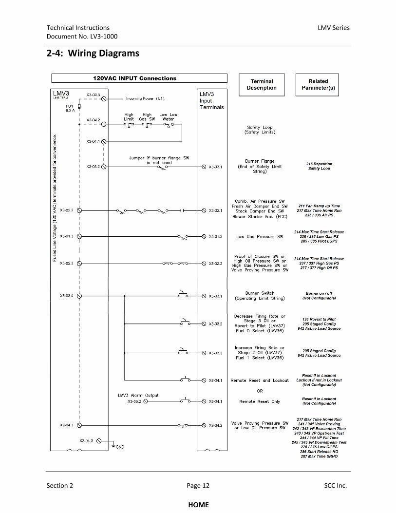
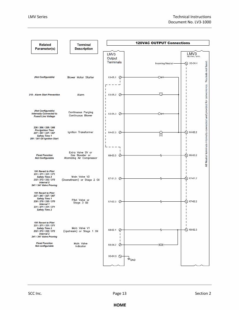
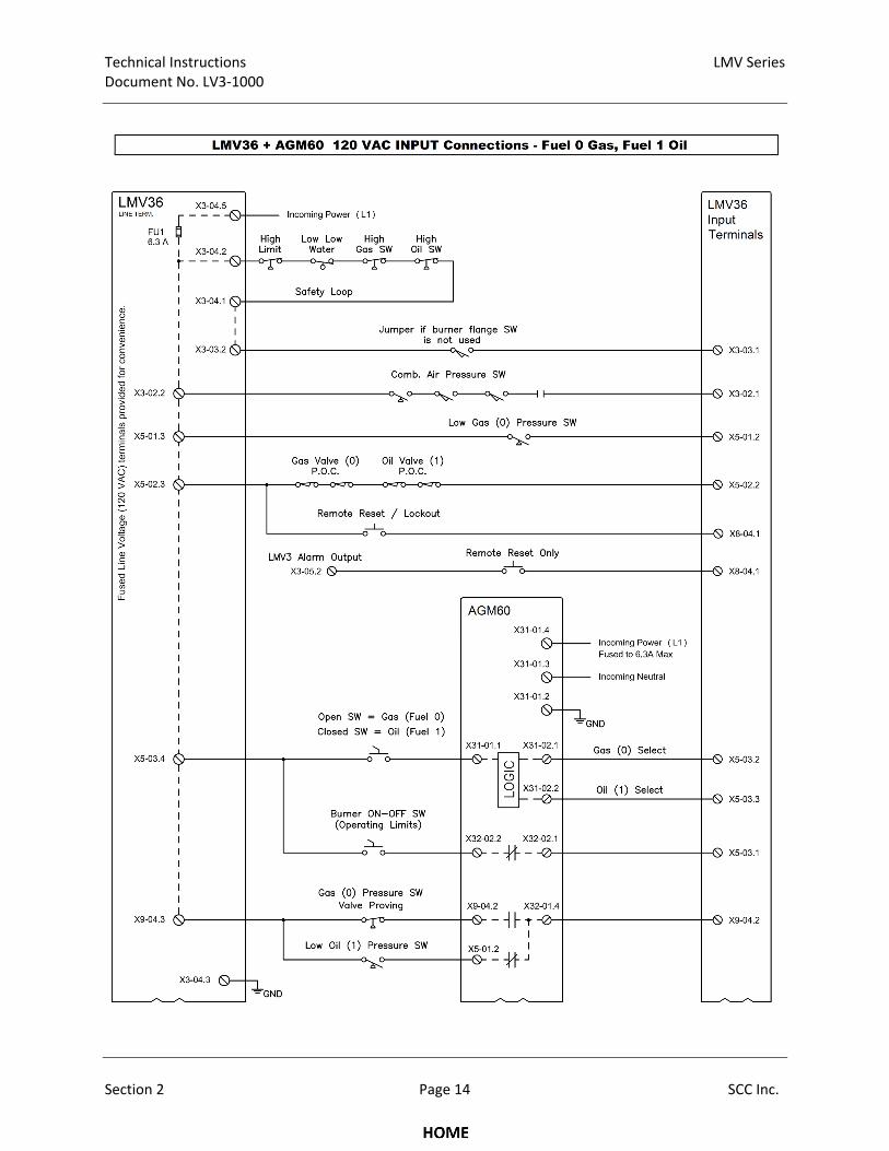
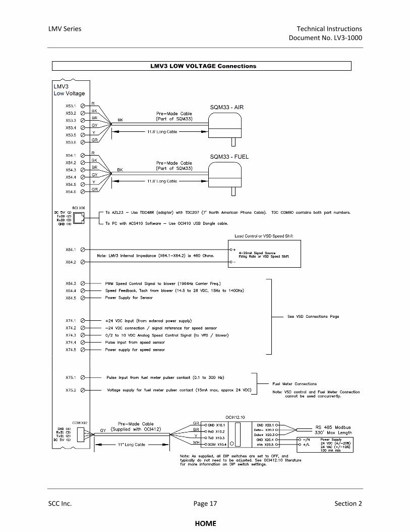
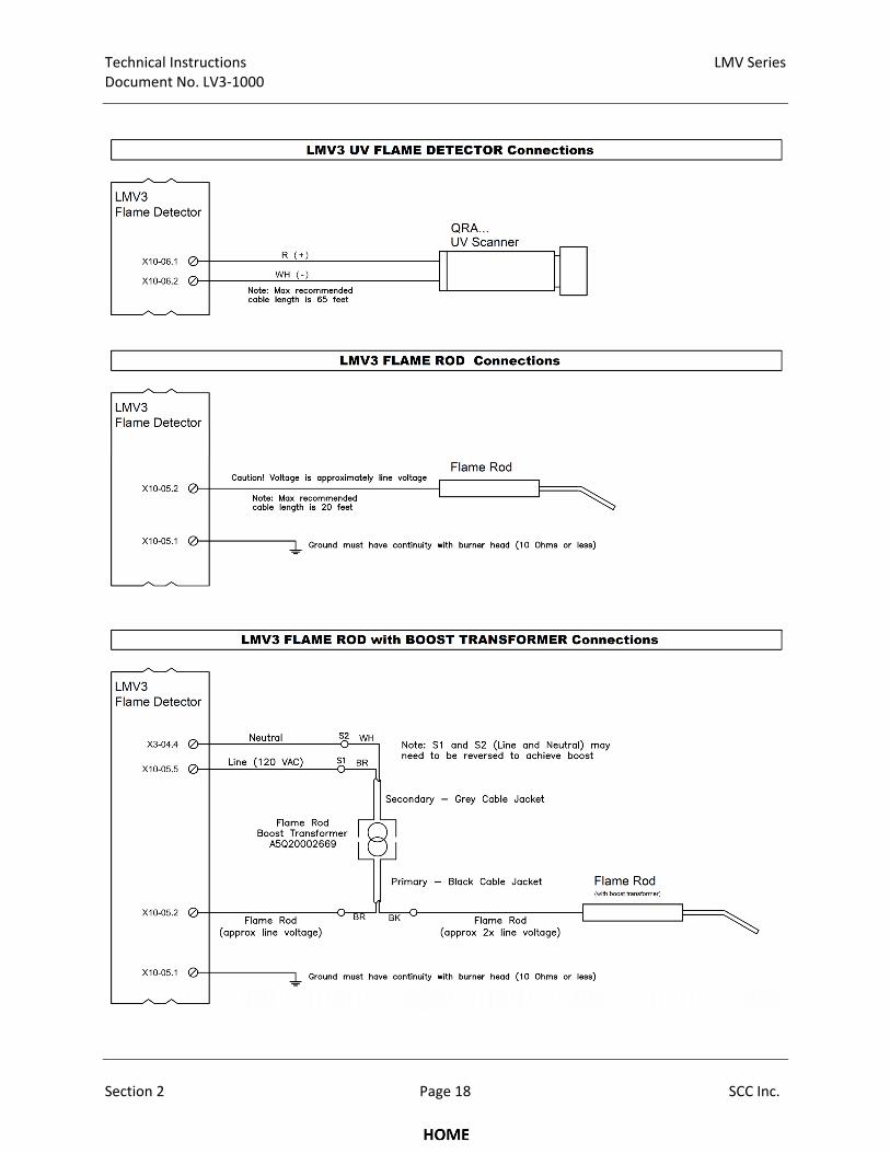
2‐4: Wiring Diagrams
LMV Series Technical Instructions Document No. LV3‐1000
SCC Inc. Page 13 Section 2
Technical Instructions LMV Series Document No. LV3‐1000
Section 2 Page 14 SCC Inc.

LMV Series Technical Instructions Document No. LV3‐1000
SCC Inc. Page 15 Section 2
Technical Instructions LMV Series Document No. LV3‐1000
Section 2 Page 16 SCC Inc.
LMV Series Technical Instructions Document No. LV3‐1000
SCC Inc. Page 17 Section 2
Technical Instructions LMV Series Document No. LV3‐1000
Section 2 Page 18 SCC Inc.

Section 1 Overview
Section 2 Wiring
Section 3 Parameters
Section 4 Commissioning
Section 5 VSD
Section 6 Troubleshooting
Section 7 Modbus
Section 8 ACS410
Appendix A Application Guide
Section 1 Overview
Section 2 Wiring
Section 3 Parameters
Section 4 Commissioning
Section 5 VSD
Section 6 Troubleshooting
Section 7 Modbus
Section 8 ACS410
Appendix A Application Guide
LMV Series Technical Instructions
Document No. LV3-1000
SCC Inc. Page 1 Section 3
Section 3: Parameters
The Siemens LMV3 has a number of parameters that can be adjusted to suit the wide variety of
applications that exist in the burner / boiler and industrial heating market.
These parameters are broken up into three main groups by password access:
User Level access does not require a password, and encompasses all of the parameters that an
end user might have to view or adjust during the life of the burner / boiler.
Service Level access does require a password, and encompasses all of the user level parameters,
plus additional parameters that a service technician might need to access to tune or
maintain the burner / boiler.
OEM Level access requires a different password than the service level, and enables the OEM to
access all available parameters, including safety-related parameters.
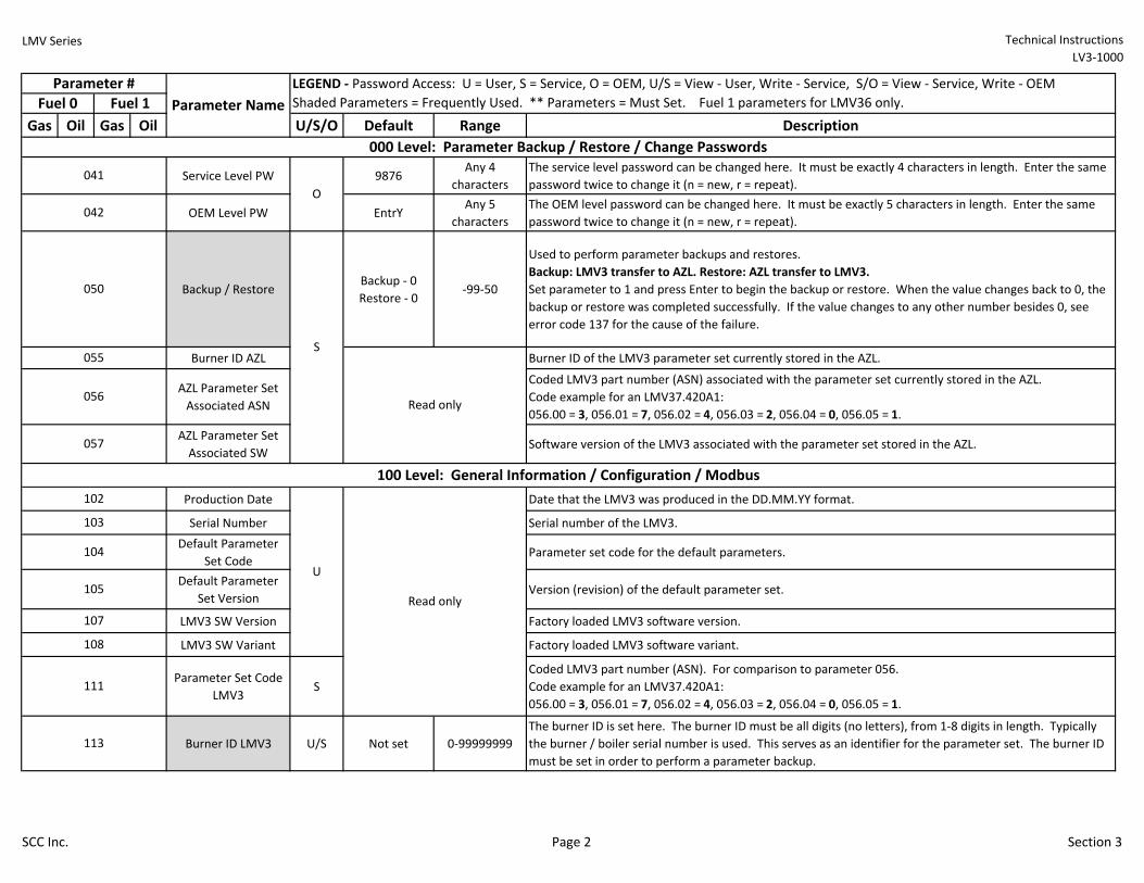
The parameters on the LMV3 are organized into groups of 100. Each group of 100 is described below:
000: Parameter backup / restore / change passwords
100: General information / configuration / Modbus
200: Settings specific to fuel 0
300: Settings specific to fuel 1 (LMV36 only)
400: Fuel-air ratio curves
500: Special positions / modulation
ramps / VSD speed shift
600: Actuators and VSD configuration
700: Fault history
800: N/A
900: Operational data
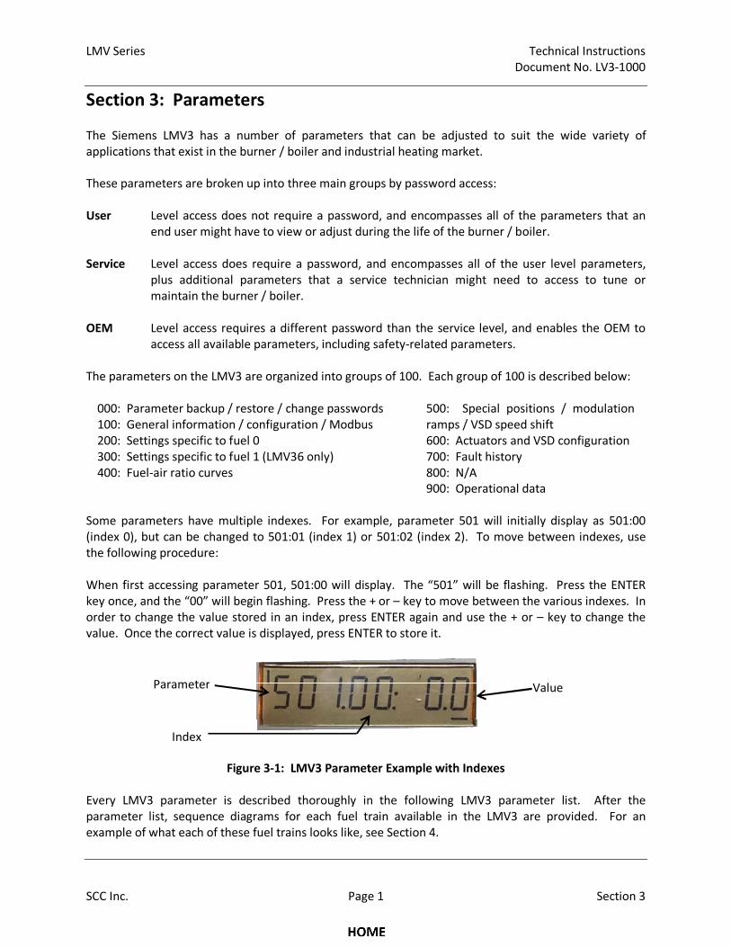
Some parameters have multiple indexes. For example, parameter 501 will initially display as 501:00
(index 0), but can be changed to 501:01 (index 1) or 501:02 (index 2). To move between indexes, use
the following procedure:
When first accessing parameter 501, 501:00 will display. The “501” will be flashing. Press the ENTER
key once, and the “00” will begin flashing. Press the + or – key to move between the various indexes. In
order to change the value stored in an index, press ENTER again and use the + or – key to change the
value. Once the correct value is displayed, press ENTER to store it.
Figure 3-1: LMV3 Parameter Example with Indexes
Every LMV3 parameter is described thoroughly in the following LMV3 parameter list. After the
parameter list, sequence diagrams for each fuel train available in the LMV3 are provided. For an
example of what each of these fuel trains looks like, see Section 4.
Value
Index
Parameter
LMV Series Technical Instructions
LV3-1000
Gas Oil Gas Oil U/S/O Default Range Description
Service Level PW 9876Any 4
characters
The service level password can be changed here. It must be exactly 4 characters in length. Enter the same
password twice to change it (n = new, r = repeat).
OEM Level PW EntrYAny 5
characters
The OEM level password can be changed here. It must be exactly 5 characters in length. Enter the same
password twice to change it (n = new, r = repeat).
Backup / RestoreBackup - 0
Restore - 0-99-50
Used to perform parameter backups and restores.
Backup: LMV3 transfer to AZL. Restore: AZL transfer to LMV3.
Set parameter to 1 and press Enter to begin the backup or restore. When the value changes back to 0, the
backup or restore was completed successfully. If the value changes to any other number besides 0, see
error code 137 for the cause of the failure.
Burner ID AZL Burner ID of the LMV3 parameter set currently stored in the AZL.
AZL Parameter Set
Associated ASN
Coded LMV3 part number (ASN) associated with the parameter set currently stored in the AZL.
Code example for an LMV37.420A1:
056.00 = 3, 056.01 = 7, 056.02 = 4, 056.03 = 2, 056.04 = 0, 056.05 = 1.
AZL Parameter Set
Associated SWSoftware version of the LMV3 associated with the parameter set stored in the AZL.
Production Date Date that the LMV3 was produced in the DD.MM.YY format.
Serial Number Serial number of the LMV3.
Default Parameter
Set CodeParameter set code for the default parameters.
Default Parameter
Set VersionVersion (revision) of the default parameter set.
LMV3 SW Version Factory loaded LMV3 software version.
LMV3 SW Variant Factory loaded LMV3 software variant.
Parameter Set Code
LMV3S
Coded LMV3 part number (ASN). For comparison to parameter 056.
Code example for an LMV37.420A1:
056.00 = 3, 056.01 = 7, 056.02 = 4, 056.03 = 2, 056.04 = 0, 056.05 = 1.
Burner ID LMV3 U/S Not set 0-99999999
The burner ID is set here. The burner ID must be all digits (no letters), from 1-8 digits in length. Typically
the burner / boiler serial number is used. This serves as an identifier for the parameter set. The burner ID
must be set in order to perform a parameter backup.
111
105Read only
102
113
Parameter #
Fuel 0 Fuel 1
041
042
107
108
LEGEND - Password Access: U = User, S = Service, O = OEM, U/S = View - User, Write - Service, S/O = View - Service, Write - OEM
Shaded Parameters = Frequently Used. ** Parameters = Must Set. Fuel 1 parameters for LMV36 only.
100 Level: General Information / Configuration / Modbus
U
000 Level: Parameter Backup / Restore / Change Passwords
O
S
050
055
056
057
103
104
Read only
Parameter Name
SCC Inc. Page 2 Section 3
LMV Series Technical Instructions
LV3-1000
Gas Oil Gas Oil U/S/O Default Range Description
Parameter #
Fuel 0 Fuel 1
LEGEND - Password Access: U = User, S = Service, O = OEM, U/S = View - User, Write - Service, S/O = View - Service, Write - OEM
Shaded Parameters = Frequently Used. ** Parameters = Must Set. Fuel 1 parameters for LMV36 only. Parameter Name
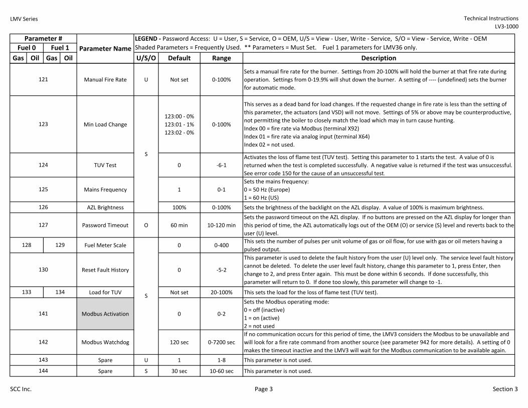
Manual Fire Rate U Not set 0-100%
Sets a manual fire rate for the burner. Settings from 20-100% will hold the burner at that fire rate during
operation. Settings from 0-19.9% will shut down the burner. A setting of ---- (undefined) sets the burner
for automatic mode.
Min Load Change
123:00 - 0%
123:01 - 1%
123:02 - 0%
0-100%
This serves as a dead band for load changes. If the requested change in fire rate is less than the setting of
this parameter, the actuators (and VSD) will not move. Settings of 5% or above may be counterproductive,
not permitting the boiler to closely match the load which may in turn cause hunting.
Index 00 = fire rate via Modbus (terminal X92)
Index 01 = fire rate via analog input (terminal X64)
Index 02 = not used.
TUV Test 0 -6-1
Activates the loss of flame test (TUV test). Setting this parameter to 1 starts the test. A value of 0 is
returned when the test is completed successfully. A negative value is returned if the test was unsuccessful.
See error code 150 for the cause of an unsuccessful test.
Mains Frequency 1 0-1
Sets the mains frequency:
0 = 50 Hz (Europe)
1 = 60 Hz (US)
AZL Brightness 100% 0-100% Sets the brightness of the backlight on the AZL display. A value of 100% is maximum brightness.
Password Timeout O 60 min 10-120 min
Sets the password timeout on the AZL display. If no buttons are pressed on the AZL display for longer than
this period of time, the AZL automatically logs out of the OEM (O) or service (S) level and reverts back to the
user (U) level.
Fuel Meter Scale 0 0-400This sets the number of pulses per unit volume of gas or oil flow, for use with gas or oil meters having a
pulsed output.
Reset Fault History 0 -5-2
This parameter is used to delete the fault history from the user (U) level only. The service level fault history
cannot be deleted. To delete the user level fault history, change this parameter to 1, press Enter, then
change to 2, and press Enter again. This must be done within 6 seconds. If done successfully, this
parameter will return to 0. If done too slowly, this parameter will change to -1.
Load for TUV Not set 20-100% This sets the load for the loss of flame test (TUV test).
Modbus Activation 0 0-2
Sets the Modbus operating mode:
0 = off (inactive)
1 = on (active)
2 = not used
Modbus Watchdog 120 sec 0-7200 sec
If no communication occurs for this period of time, the LMV3 considers the Modbus to be unavailable and
will look for a fire rate command from another source (see parameter 942 for more details). A setting of 0
makes the timeout inactive and the LMV3 will wait for the Modbus communication to be available again.
Spare U 1 1-8 This parameter is not used.
Spare S 30 sec 10-60 sec This parameter is not used.
126
127
123
124
125
121
142
S
143
144
128 129
130
133 134
141
S
SCC Inc. Page 3 Section 3

LMV Series Technical Instructions
LV3-1000
Gas Oil Gas Oil U/S/O Default Range Description
Parameter #
Fuel 0 Fuel 1
LEGEND - Password Access: U = User, S = Service, O = OEM, U/S = View - User, Write - Service, S/O = View - Service, Write - OEM
Shaded Parameters = Frequently Used. ** Parameters = Must Set. Fuel 1 parameters for LMV36 only. Parameter Name
Modbus Address 1 1-247 Sets the LMV3 address for Modbus (job specific).
Baud Rate 1 0-1
Sets the baud rate of the Modbus port X92:
0 = 9600 bit/s
1 = 19200 bit/s
Parity 0 0-2
Sets the parity of the Modbus port X92:
0 = none
1 = odd
2 = even
Default Load Not set 0-100%This sets the fire rate when Modbus communication is interrupted. A setting from 20-100% will set the
output of the burner. A setting of 0-19.9% will shut down the burner.
Total Faults Displays the total number of faults the LMV3 has received. Not resettable.
Operating HoursDisplays the total number of hours in operation. This value can be reset by pressing the left or right arrow
to change the value to 0 and then pressing Enter.
Powered Hours Displays the total number of hours the LMV3 has been powered. Not resettable.
StartupsDisplays the total number of startups. This value can be reset by pressing the left or right arrow to change
the value to 0 and then pressing Enter.
Parameter only exists on an LMV36: Displays the total number of startups. Not resettable.
Displays the total number of startups on both fuels (LMV36), or total startups (LMV37). Not resettable.
Fuel UsedDisplays the totalized volume of fuel. This value can be reset by pressing the left or right arrow to change
the value to 0 and then pressing Enter.
Total RevertParameter only exists on an LMV37: Displays the total number of times the burner has used the "revert to
pilot" function to switch back to running on the pilot only. Not resettable.
Flame Failure
Response Time (FFRT)O
186:00 = 0
186:01 = 0
187:00 = 0
187.01 = 0
0-30
Sets the flame failure response time (FFRT). The LMV3 has a base flame failure response time of
approximately 1 second. This setting adds tenths of a second to the base time. For example, the maximum
setting of 30 adds 3 seconds to the 1 second base time for a total flame failure response time of 4 seconds.
Index 00 = Flame failure response time when using a QRB... flame scanner
Index 01 = Flame failure response time when using a QRA... flame scanner or a flame rod
Lockout Position S 0 0-1
This setting determines the position that the actuators and VSD will drive to when a lockout occurs:
0 = home position
1 = postpurge position
Reset only
Reset only
161
162 172
164
166
167
174
165 175
177
Read only
Read only
Reset only
Total Startups
Read only
145
146
147
148 149
176 -
U
163
Read only
186 187
190
S
SCC Inc. Page 4 Section 3
LMV Series Technical Instructions
LV3-1000
Gas Oil Gas Oil U/S/O Default Range Description
Parameter #
Fuel 0 Fuel 1
LEGEND - Password Access: U = User, S = Service, O = OEM, U/S = View - User, Write - Service, S/O = View - Service, Write - OEM
Shaded Parameters = Frequently Used. ** Parameters = Must Set. Fuel 1 parameters for LMV36 only. Parameter Name
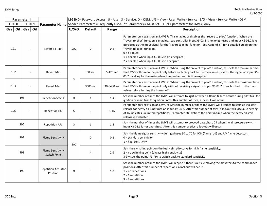
Revert To Pilot S/O 0 0-2
Parameter only exists on an LMV37: This enables or disables the "revert to pilot" function. When the
"revert to pilot" function is enabled, load controller input X5-03.3 is no longer used and input X5-03.2 is re-
purposed as the input signal for the "revert to pilot" function. See Appendix A for a detailed guide on the
"revert to pilot" function.
0 = disabled
1 = enabled when input X5-03.2 is de-energized
2 = enabled when input X5-03.2 is energized
Revert Min 30 sec 5-120 sec
Parameter only exists on an LMV37: When using the "revert to pilot" function, this sets the minimum time
the LMV3 will run on the pilot only before switching back to the main valves, even if the signal on input X5-
03.2 is calling for the main valves to open before this time expires.
Revert Max 3600 sec 30-6480 sec
Parameter only exists on an LMV37: When using the "revert to pilot" function, this sets the maximum time
the LMV3 will run on the pilot only without receiving a signal on input X5-03.2 to switch back to the main
valves before turning the burner off.
Repetition Safe 1 O 1 1-4Sets the number of times the LMV3 will attempt to light-off when a flame failure occurs during pilot trial for
ignition or main trial for ignition. After this number of tries, a lockout will occur.
Repetition HO S 3 1-16
Parameter only exists on an LMV37: Sets the number of times the LMV3 will attempt to start up if a start
release for heavy oil is not met on input X9-04.2. After this number of tries, a lockout will occur. A setting
of 16 indicates unlimited repetitions. Parameter 286 defines the point in time when the heavy oil start
release is evaluated.
Repetition APS O 1 1-2Sets the number of times the LMV3 will attempt to proceed past phase 24 when the air pressure switch
input X3-02.1 is not energized. After this number of tries, a lockout will occur.
Flame Sensitivity 0 0-1
Sets the flame signal sensitivity during phases 60 to 70 for ION (flame rod) and UV flame detectors.
0 = standard sensitivity
1 = high sensitivity
Flame Sensitivity
Switch Point4 2-9
Sets the switching point on the fuel / air ratio curve for high flame sensitivity.
2 = no switching point (always high sensitivity)
3-9 = sets the point (P3-P9) to switch back to standard sensitivity
Repetition Actuator
PositionO 3 1-3
Sets the number of times the LMV3 will recycle if there is a issue moving the actuators to the commanded
positions. After this number of repetitions, a lockout will occur.
1 = no repetitions
2 = 1 repetition
3 = 2 repetitions
198
199
S/O
196
191 -
192
197
194
-
193 -
195 -
S
SCC Inc. Page 5 Section 3
LMV Series Technical Instructions
LV3-1000
Gas Oil Gas Oil U/S/O Default Range Description
Parameter #
Fuel 0 Fuel 1
LEGEND - Password Access: U = User, S = Service, O = OEM, U/S = View - User, Write - Service, S/O = View - Service, Write - OEM
Shaded Parameters = Frequently Used. ** Parameters = Must Set. Fuel 1 parameters for LMV36 only. Parameter Name
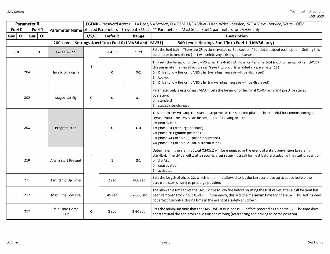
Fuel Train** Not set 1-29Sets the fuel train. There are 29 options available. See section 4 for details about each option. Setting this
parameter to undefined (----) will delete any existing fuel curves.
Invalid Analog In 0 0-2
This sets the behavior of the LMV3 when the 4-20 mA signal on terminal X64 is out of range. On an LMV37,
this parameter has no effect unless "revert to pilot" is enabled via parameter 191.
0 = Drive to low fire or no VSD trim (warning message will be displayed)
1 = Lockout
2 = Drive to low fire or no VSD trim (no warning message will be displayed)
Staged Config O 0 0-1
Parameter only exists on an LMV37. Sets the behavior of terminal X5-03 pin 2 and pin 3 for staged
operation:
0 = standard
1 = stages interchanged
Program Stop 0 0-4
This parameter will stop the startup sequence in the selected phase. This is useful for commissioning and
service work. The LMV3 can be held in the following phases:
0 = deactivated
1 = phase 24 (prepurge position)
2 = phase 36 (ignition position)
3 = phase 44 (interval 1 - pilot stabilization)
4 = phase 52 (interval 2 - main stabilization)
Alarm Start Prevent 1 0-1
Determines if the alarm output X3-05.2 will be energized in the event of a start prevention (an alarm in
standby). The LMV3 will wait 5 seconds after receiving a call for heat before displaying the start prevention
on the AZL.
0 = deactivated
1 = activated
Fan Ramp Up Time 2 sec 2-60 secSets the length of phase 22, which is the time allowed to let the fan accelerate up to speed before the
actuators start driving to prepurge position.
Max Time Low Fire 45 sec 0.2-600 sec
The allowable time to let the LMV3 drive to low fire before shutting the fuel valves after a call for heat has
been removed from input X5-03.1. In summary, this sets the maximum time for phase 62. This setting does
not affect fuel valve closing time in the event of a safety shutdown.
Min Time Home
RunO 2 sec 2-60 sec
Sets the minimum time that the LMV3 will stay in phase 10 before proceeding to phase 12. The time does
not start until the actuators have finished moving (referencing and driving to home position).
208
210
211
212
204
S
201 301
205
213
S
200 Level: Settings Specific to Fuel 0 (LMV36 and LMV37) 300 Level: Settings Specific to Fuel 1 (LMV36 only)
SCC Inc. Page 6 Section 3
LMV Series Technical Instructions
LV3-1000
Gas Oil Gas Oil U/S/O Default Range Description
Parameter #
Fuel 0 Fuel 1
LEGEND - Password Access: U = User, S = Service, O = OEM, U/S = View - User, Write - Service, S/O = View - Service, Write - OEM
Shaded Parameters = Frequently Used. ** Parameters = Must Set. Fuel 1 parameters for LMV36 only. Parameter Name
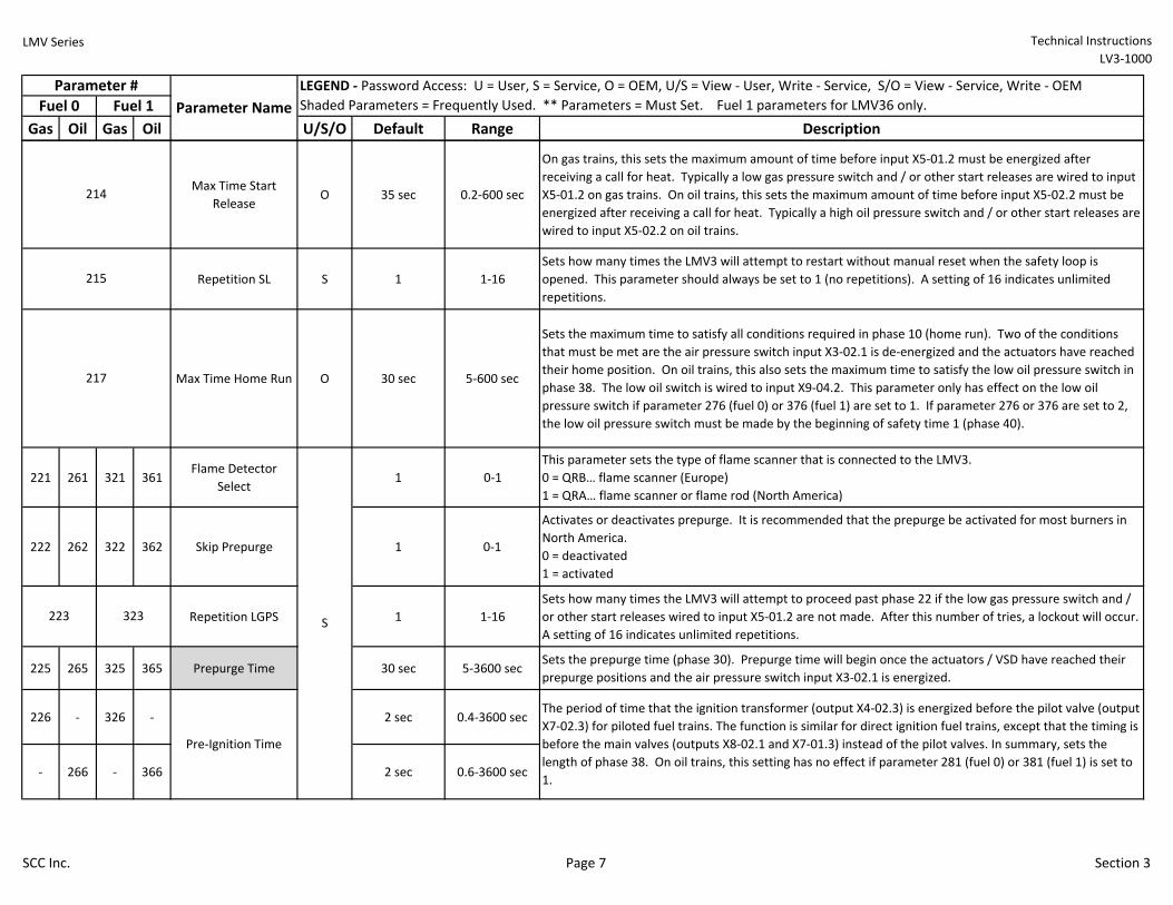
Max Time Start
ReleaseO 35 sec 0.2-600 sec
On gas trains, this sets the maximum amount of time before input X5-01.2 must be energized after
receiving a call for heat. Typically a low gas pressure switch and / or other start releases are wired to input
X5-01.2 on gas trains. On oil trains, this sets the maximum amount of time before input X5-02.2 must be
energized after receiving a call for heat. Typically a high oil pressure switch and / or other start releases are
wired to input X5-02.2 on oil trains.
Repetition SL S 1 1-16
Sets how many times the LMV3 will attempt to restart without manual reset when the safety loop is
opened. This parameter should always be set to 1 (no repetitions). A setting of 16 indicates unlimited
repetitions.
Max Time Home Run O 30 sec 5-600 sec
Sets the maximum time to satisfy all conditions required in phase 10 (home run). Two of the conditions
that must be met are the air pressure switch input X3-02.1 is de-energized and the actuators have reached
their home position. On oil trains, this also sets the maximum time to satisfy the low oil pressure switch in
phase 38. The low oil switch is wired to input X9-04.2. This parameter only has effect on the low oil
pressure switch if parameter 276 (fuel 0) or 376 (fuel 1) are set to 1. If parameter 276 or 376 are set to 2,
the low oil pressure switch must be made by the beginning of safety time 1 (phase 40).
221 261 321 361Flame Detector
Select1 0-1
This parameter sets the type of flame scanner that is connected to the LMV3.
0 = QRB… flame scanner (Europe)
1 = QRA… flame scanner or flame rod (North America)
222 262 322 362 Skip Prepurge 1 0-1
Activates or deactivates prepurge. It is recommended that the prepurge be activated for most burners in
North America.
0 = deactivated
1 = activated
Repetition LGPS 1 1-16
Sets how many times the LMV3 will attempt to proceed past phase 22 if the low gas pressure switch and /
or other start releases wired to input X5-01.2 are not made. After this number of tries, a lockout will occur.
A setting of 16 indicates unlimited repetitions.
225 265 325 365 Prepurge Time 30 sec 5-3600 secSets the prepurge time (phase 30). Prepurge time will begin once the actuators / VSD have reached their
prepurge positions and the air pressure switch input X3-02.1 is energized.
226 - 326 - 2 sec 0.4-3600 sec
- 266 - 366 2 sec 0.6-3600 sec
The period of time that the ignition transformer (output X4-02.3) is energized before the pilot valve (output
X7-02.3) for piloted fuel trains. The function is similar for direct ignition fuel trains, except that the timing is
before the main valves (outputs X8-02.1 and X7-01.3) instead of the pilot valves. In summary, sets the
length of phase 38. On oil trains, this setting has no effect if parameter 281 (fuel 0) or 381 (fuel 1) is set to
1.
223 323
214
215
217
Pre-Ignition Time
S
SCC Inc. Page 7 Section 3
LMV Series Technical Instructions
LV3-1000
Gas Oil Gas Oil U/S/O Default Range Description
Parameter #
Fuel 0 Fuel 1
LEGEND - Password Access: U = User, S = Service, O = OEM, U/S = View - User, Write - Service, S/O = View - Service, Write - OEM
Shaded Parameters = Frequently Used. ** Parameters = Must Set. Fuel 1 parameters for LMV36 only. Parameter Name
227 - 327 - 5 sec 1-10 sec
- 267 - 367 5 sec 1-15 sec
229 - 329 - 1.8 sec 0.4-9.6 sec
- 269 - 369 1.8 sec 0.4-14 sec
230 - 330 - 2 sec 0.4-60 sec
- 270 - 370 2 sec 0.4-60 sec
231 - 331 - 7 sec 1-10 sec
- 271 - 371 10 sec 1-15 sec
232 - 332 - 2 sec 0.4-60 sec
- 272 - 372 2 sec 0.4-60 sec
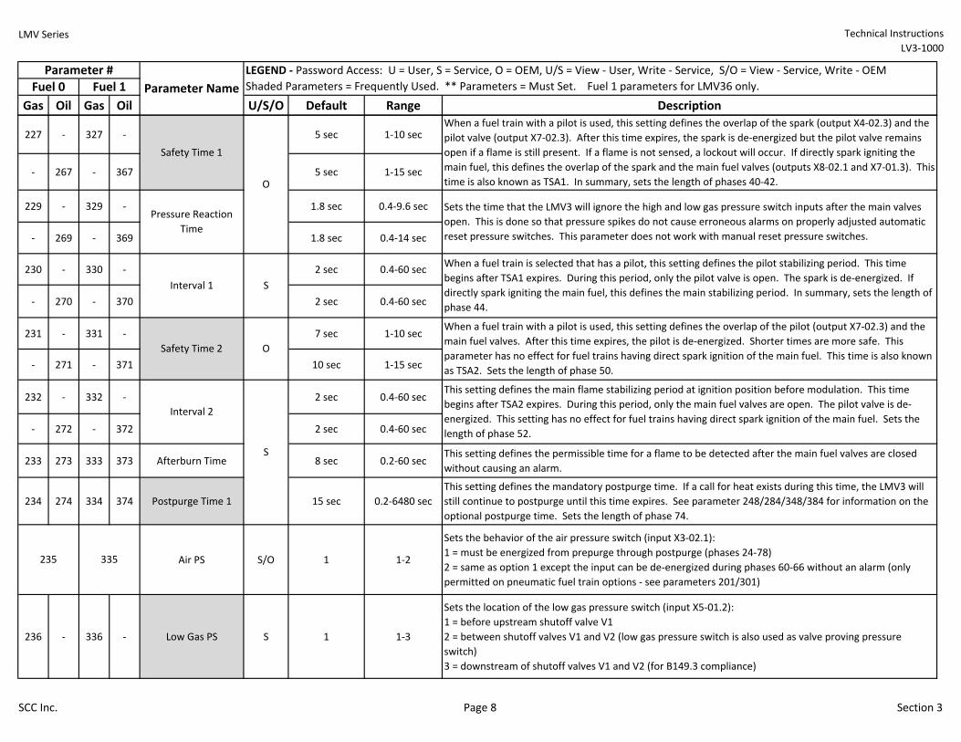
233 273 333 373 Afterburn Time 8 sec 0.2-60 secThis setting defines the permissible time for a flame to be detected after the main fuel valves are closed
without causing an alarm.
234 274 334 374 Postpurge Time 1 15 sec 0.2-6480 sec
This setting defines the mandatory postpurge time. If a call for heat exists during this time, the LMV3 will
still continue to postpurge until this time expires. See parameter 248/284/348/384 for information on the
optional postpurge time. Sets the length of phase 74.
Air PS S/O 1 1-2
Sets the behavior of the air pressure switch (input X3-02.1):
1 = must be energized from prepurge through postpurge (phases 24-78)
2 = same as option 1 except the input can be de-energized during phases 60-66 without an alarm (only
permitted on pneumatic fuel train options - see parameters 201/301)
236 - 336 - Low Gas PS S 1 1-3
Sets the location of the low gas pressure switch (input X5-01.2):
1 = before upstream shutoff valve V1
2 = between shutoff valves V1 and V2 (low gas pressure switch is also used as valve proving pressure
switch)
3 = downstream of shutoff valves V1 and V2 (for B149.3 compliance)
When a fuel train with a pilot is used, this setting defines the overlap of the spark (output X4-02.3) and the
pilot valve (output X7-02.3). After this time expires, the spark is de-energized but the pilot valve remains
open if a flame is still present. If a flame is not sensed, a lockout will occur. If directly spark igniting the
main fuel, this defines the overlap of the spark and the main fuel valves (outputs X8-02.1 and X7-01.3). This
time is also known as TSA1. In summary, sets the length of phases 40-42.
Sets the time that the LMV3 will ignore the high and low gas pressure switch inputs after the main valves
open. This is done so that pressure spikes do not cause erroneous alarms on properly adjusted automatic
reset pressure switches. This parameter does not work with manual reset pressure switches.
O
235 335
S
When a fuel train is selected that has a pilot, this setting defines the pilot stabilizing period. This time
begins after TSA1 expires. During this period, only the pilot valve is open. The spark is de-energized. If
directly spark igniting the main fuel, this defines the main stabilizing period. In summary, sets the length of
phase 44.
O
When a fuel train with a pilot is used, this setting defines the overlap of the pilot (output X7-02.3) and the
main fuel valves. After this time expires, the pilot is de-energized. Shorter times are more safe. This
parameter has no effect for fuel trains having direct spark ignition of the main fuel. This time is also known
as TSA2. Sets the length of phase 50.
This setting defines the main flame stabilizing period at ignition position before modulation. This time
begins after TSA2 expires. During this period, only the main fuel valves are open. The pilot valve is de-
energized. This setting has no effect for fuel trains having direct spark ignition of the main fuel. Sets the
length of phase 52.
S
Safety Time 1
Pressure Reaction
Time
Interval 1
Safety Time 2
Interval 2
SCC Inc. Page 8 Section 3
LMV Series Technical Instructions
LV3-1000
Gas Oil Gas Oil U/S/O Default Range Description
Parameter #
Fuel 0 Fuel 1
LEGEND - Password Access: U = User, S = Service, O = OEM, U/S = View - User, Write - Service, S/O = View - Service, Write - OEM
Shaded Parameters = Frequently Used. ** Parameters = Must Set. Fuel 1 parameters for LMV36 only. Parameter Name
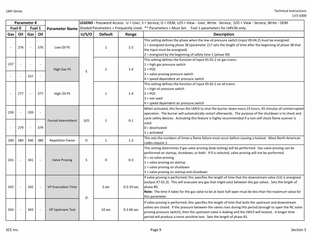
- 276 - 376 Low Oil PS 1 1-2
This setting defines the phase when the low oil pressure switch (input X9-04.2) must be energized:
1 = energized during phase 38 (parameter 217 sets the length of time after the beginning of phase 38 that
the input must be energized)
2 = energized by the beginning of safety time 1 (phase 40)
237 - - -
- - 337 -
- 277 - 377 High Oil PS 1 1-4
This setting defines the function of input X5-02.2 on oil trains:
1 = high oil pressure switch
2 = POC
3 = not used
4 = speed dependent air pressure switch
239 - 339 -
- 279 - 379
240 280 340 380 Repetition Flame O 1 1-2This sets the numbers of times a flame failure must occur before causing a lockout. Most North American
codes require 1.
241 - 341 - Valve Proving S 0 0-3
This setting determines if gas valve proving (leak testing) will be performed. Gas valve proving can be
performed on startup, shutdown, or both. If 0 is selected, valve proving will not be performed.
0 = no valve proving
1 = valve proving on startup
2 = valve proving on shutdown
3 = valve proving on startup and shutdown
242 - 342 - VP Evacuation Time 3 sec 0.2-10 sec
If valve proving is performed, this specifies the length of time that the downstream valve (V2) is energized
(output X7-01.3). This will evacuate any gas that might exist between the gas valves. Sets the length of
phase 80.
Note: The time it takes for the gas valve to be at least half open must be less than the maximum value for
this parameter.
243 - 343 - VP Upstream Test 10 sec 0.2-60 sec
If valve proving is performed, this specifies the length of time that both the upstream and downstream
valves are closed. If the pressure between the valves rises during this period (enough to open the NC valve
proving pressure switch), then the upstream valve is leaking and the LMV3 will lockout. A longer time
period will produce a more sensitive test. Sets the length of phase 81.
1-4
This setting defines the function of input X5-02.2 on gas trains:
1 = high gas pressure switch
2 = POC
3 = valve proving pressure switch
4 = speed dependent air pressure switch
S/O
S2High Gas PS
Forced Intermittent
When activated, this forces the LMV3 to shut the burner down every 23 hours, 45 minutes of uninterrupted
operation. The burner will automatically restart afterwards. The purpose of the shutdown is to check and
cycle safety devices. Activating this feature is highly recommended if a non-self check flame scanner is
used.
0 = deactivated
1 = activated
0-11
O
SCC Inc. Page 9 Section 3
LMV Series Technical Instructions
LV3-1000
Gas Oil Gas Oil U/S/O Default Range Description
Parameter #
Fuel 0 Fuel 1
LEGEND - Password Access: U = User, S = Service, O = OEM, U/S = View - User, Write - Service, S/O = View - Service, Write - OEM
Shaded Parameters = Frequently Used. ** Parameters = Must Set. Fuel 1 parameters for LMV36 only. Parameter Name
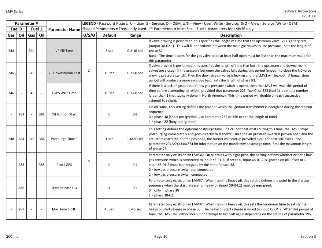
244 - 344 - VP Fill Time 3 sec 0.2-10 sec
If valve proving is performed, this specifies the length of time that the upstream valve (V1) is energized
(output X8-02.1). This will fill the volume between the main gas valves to line pressure. Sets the length of
phase 82.
Note: The time it takes for the gas valve to be at least half open must be less than the maximum value for
this parameter.
245 - 345 - VP Downstream Test 10 sec 0.2-60 sec
If valve proving is performed, this specifies the length of time that both the upstream and downstream
valves are closed. If the pressure between the valves falls during this period (enough to close the NC valve
proving pressure switch), then the downstream valve is leaking and the LMV3 will lockout. A longer time
period will produce a more sensitive test. Sets the length of phase 83.
246 - 346 - LGPS Wait Time 10 sec 0.2-60 sec
If there is a lack of gas pressure (low gas pressure switch is open), then the LMV3 will wait this period of
time before attempting to relight, provided that parameter 223 (fuel 0) or 323 (fuel 1) is set to a number
larger than 1 (not typically done in North America). This time period will double on each successive
attempt to relight.
- 281 - 381 Oil Ignition Start 0 0-1
On oil trains, this setting defines the point at which the ignition transformer is energized during the startup
sequence:
0 = phase 38 (short pre-ignition, use parameter 266 or 366 to set the length of time)
1 = phase 22 (long pre-ignition)
248 284 348 384 Postpurge Time 3 1 sec 1-6480 sec
This setting defines the optional postpurge time. If a call for heat exists during this time, the LMV3 stops
postpurging immediately and goes directly to standby. Once the air pressure switch is proven open and the
actuators reach their home positions, the burner will startup provided a call for heat still exists. See
parameter 234/274/334/374 for information on the mandatory postpurge time. Sets the maximum length
of phase 78.
- 285 - 385 Pilot LGPS 0 0-1
Parameter only exists on an LMV36: On oil trains with a gas pilot, this setting defines whether or not a low
gas pressure switch is connected to input X5-01.2. If set to 0, input X5-01.2 is ignored on oil. If set to 1,
input X5-01.2 must be energized by the end of phase 38.
0 = low gas pressure switch not connected
1 = low gas pressure switch connected
- 286 - - Start Release HO 1 0-1
Parameter only exists on an LMV37: When running heavy oil, this setting defines the point in the startup
sequence when the start release for heavy oil (input X9-04.2) must be energized.
0 = only in phase 38
1 = phase 38-62
- 287 - - Max Time SRHO 45 sec 1-45 sec
Parameter only exists on an LMV37: When running heavy oil, this sets the maximum time to satisfy the
heavy oil start release in phase 38. The heavy oil start release is wired to input X9-04.2. After this period of
time, the LMV3 will either lockout or attempt to light-off again depending on the setting of parameter 195.
S
O
SCC Inc. Page 10 Section 3
LMV Series Technical Instructions
LV3-1000
Gas Oil Gas Oil U/S/O Default Range Description
Parameter #
Fuel 0 Fuel 1
LEGEND - Password Access: U = User, S = Service, O = OEM, U/S = View - User, Write - Service, S/O = View - Service, Write - OEM
Shaded Parameters = Frequently Used. ** Parameters = Must Set. Fuel 1 parameters for LMV36 only. Parameter Name
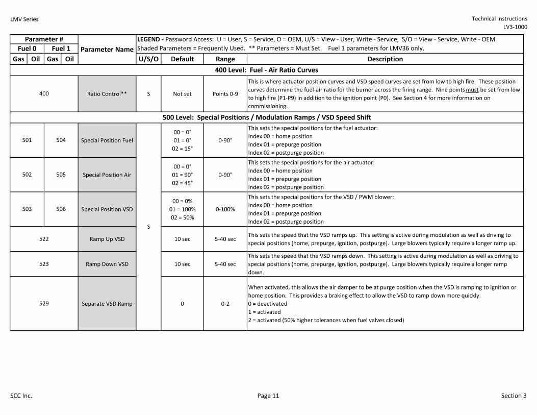
Ratio Control** S Not set Points 0-9
This is where actuator position curves and VSD speed curves are set from low to high fire. These position
curves determine the fuel-air ratio for the burner across the firing range. Nine points must be set from low
to high fire (P1-P9) in addition to the ignition point (P0). See Section 4 for more information on
commissioning.
Special Position Fuel
00 = 0°
01 = 0°
02 = 15°
0-90°
This sets the special positions for the fuel actuator:
Index 00 = home position
Index 01 = prepurge position
Index 02 = postpurge position
Special Position Air
00 = 0°
01 = 90°
02 = 45°
0-90°
This sets the special positions for the air actuator:
Index 00 = home position
Index 01 = prepurge position
Index 02 = postpurge position
Special Position VSD
00 = 0%
01 = 100%
02 = 50%
0-100%
This sets the special positions for the VSD / PWM blower:
Index 00 = home position
Index 01 = prepurge position
Index 02 = postpurge position
Ramp Up VSD 10 sec 5-40 secThis sets the speed that the VSD ramps up. This setting is active during modulation as well as driving to
special positions (home, prepurge, ignition, postpurge). Large blowers typically require a longer ramp up.
Ramp Down VSD 10 sec 5-40 sec
This sets the speed that the VSD ramps down. This setting is active during modulation as well as driving to
special positions (home, prepurge, ignition, postpurge). Large blowers typically require a longer ramp
down.
Separate VSD Ramp 0 0-2
When activated, this allows the air damper to be at purge position when the VSD is ramping to ignition or
home position. This provides a braking effect to allow the VSD to ramp down more quickly.
0 = deactivated
1 = activated
2 = activated (50% higher tolerances when fuel valves closed)
S
502 505
503 506
522
523
500 Level: Special Positions / Modulation Ramps / VSD Speed Shift
400 Level: Fuel - Air Ratio Curves
400
529
501 504
SCC Inc. Page 11 Section 3
LMV Series Technical Instructions
LV3-1000
Gas Oil Gas Oil U/S/O Default Range Description
Parameter #
Fuel 0 Fuel 1
LEGEND - Password Access: U = User, S = Service, O = OEM, U/S = View - User, Write - Service, S/O = View - Service, Write - OEM
Shaded Parameters = Frequently Used. ** Parameters = Must Set. Fuel 1 parameters for LMV36 only. Parameter Name
VSD Speed Shift S/O 0 0-4
This setting enables 4-20 mA input X64 as the input for shifting the VSD speed off of the base curve. If
activated, terminal X64 will no longer accept a 4-20 mA input for the load. There are two additional options
to consider when activating VSD shift. The first is to enable the controller sending the 4-20 mA signal to
test the analog input during phases 24-30 (prepurge). The second is to enable ignition speed shift so that
the VSD speed at ignition position can be shifted to provide a more rich light off when the boiler is cold.
0 = deactivated (X64 remains as a 4-20 mA load input)
1 = activated
2 = activated (with analog input test)
3 = activated (with ignition speed shift)
4 = activated (with analog input test and ignition speed shift)
VSD Activation 0 0-1
This setting activates or deactivates a VSD:
0 = VSD deactivated
1 = VSD activated
Modulation Ramp 32 sec 32-80 sec
This setting controls the speed at which the actuators will ramp during phases 60-62 (fuel valves open). The
time chosen is how long it would actually take for the actuators to drive from 0-90°. During all other
phases, the actuator ramp speed is fixed depending on the model of the SQM33 actuator being used
(SQM33.5 = 5 sec, SQM33.7 = 17 sec). If using a VSD, this time should be set at least 20% longer than the
longest VSD ramp time (parameters 522 and 523).
Load Low Fire Not set 20-100% Sets the low fire load. During normal operation, the burner will not modulate below this point.
Load High Fire Not set 20-100% Sets the high fire load. During normal operation, the burner will not modulate above this point.
VSD Shift Low -4% -15-0%Sets the absolute lower limit for VSD speed shift. This percentage is based on the standardized speed
(parameter 642).
VSD Shift High 4% 0-25%Sets the absolute upper limit for VSD speed shift. This percentage is based on the standardized speed
(parameter 642).
Shift Attenuation 88% 0-100%
The attenuation factor for VSD speed shift. This setting gives the ability to have less VSD shift at low fire for
a given analog input signal. 100% attenuation means that there will be no shift at low fire and maximum
shift at high fire with a linear interpolation between. A setting of 0% results in no attenuation, so the full
measure of VSD shift will be used at all firing rates.
Shift Delay 25 sec 0-255 sec
This setting is a delay timer for VSD speed shift. After the LMV3 reaches normal operation (phase 60), this
delay timer starts. After this time expires, the 4-20 mA input on X64 will be used to shift the VSD speed. A
setting of 0 seconds deactivates this feature.
Shift Limit Time 0 sec 0-3600 sec
If the LMV3 is at the upper or lower VSD shift limit (parameters 547/567 or 548/568) for this amount of
time, a warning message will be displayed or a shutdown will occur, depending on the setting of parameter
552/572. A setting of 0 seconds deactivates this feature.
Shift Limit Response 0 0-2
Determines the action of the LMV3 if the VSD shift limits are reached:
0 = warning only
1 = warning and VSD shift deactivation
2 = shutdown
S/O
551
567
568
569
570
571
546 566
542
552 572
530
544
545 565
S
547
548
549
550
SCC Inc. Page 12 Section 3
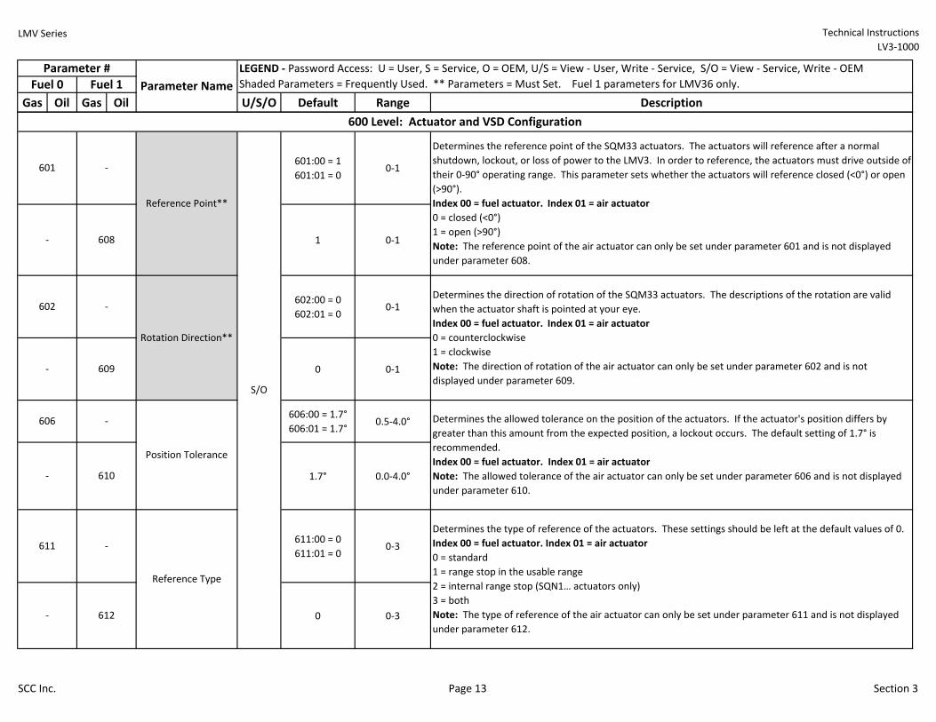
LMV Series Technical Instructions
LV3-1000
Gas Oil Gas Oil U/S/O Default Range Description
Parameter #
Fuel 0 Fuel 1
LEGEND - Password Access: U = User, S = Service, O = OEM, U/S = View - User, Write - Service, S/O = View - Service, Write - OEM
Shaded Parameters = Frequently Used. ** Parameters = Must Set. Fuel 1 parameters for LMV36 only. Parameter Name
601:00 = 1
601:01 = 00-1
1 0-1
602:00 = 0
602:01 = 00-1
0 0-1
606:00 = 1.7°
606:01 = 1.7°0.5-4.0°
1.7° 0.0-4.0°
611:00 = 0
611:01 = 00-3
0 0-3
609
Reference Point**
- 612
Determines the type of reference of the actuators. These settings should be left at the default values of 0.
Index 00 = fuel actuator. Index 01 = air actuator
0 = standard
1 = range stop in the usable range
2 = internal range stop (SQN1… actuators only)
3 = both
Note: The type of reference of the air actuator can only be set under parameter 611 and is not displayed
under parameter 612.
Position Tolerance
Reference Type
Determines the direction of rotation of the SQM33 actuators. The descriptions of the rotation are valid
when the actuator shaft is pointed at your eye.
Index 00 = fuel actuator. Index 01 = air actuator
0 = counterclockwise
1 = clockwise
Note: The direction of rotation of the air actuator can only be set under parameter 602 and is not
displayed under parameter 609.
Rotation Direction**
600 Level: Actuator and VSD Configuration
Determines the reference point of the SQM33 actuators. The actuators will reference after a normal
shutdown, lockout, or loss of power to the LMV3. In order to reference, the actuators must drive outside of
their 0-90° operating range. This parameter sets whether the actuators will reference closed (<0°) or open
(>90°).
Index 00 = fuel actuator. Index 01 = air actuator
0 = closed (<0°)
1 = open (>90°)
Note: The reference point of the air actuator can only be set under parameter 601 and is not displayed
under parameter 608.
-
601 -
602 -
606 -
611 -
Determines the allowed tolerance on the position of the actuators. If the actuator's position differs by
greater than this amount from the expected position, a lockout occurs. The default setting of 1.7° is
recommended.
Index 00 = fuel actuator. Index 01 = air actuator
Note: The allowed tolerance of the air actuator can only be set under parameter 606 and is not displayed
under parameter 610.
-
S/O
- 610
608
SCC Inc. Page 13 Section 3
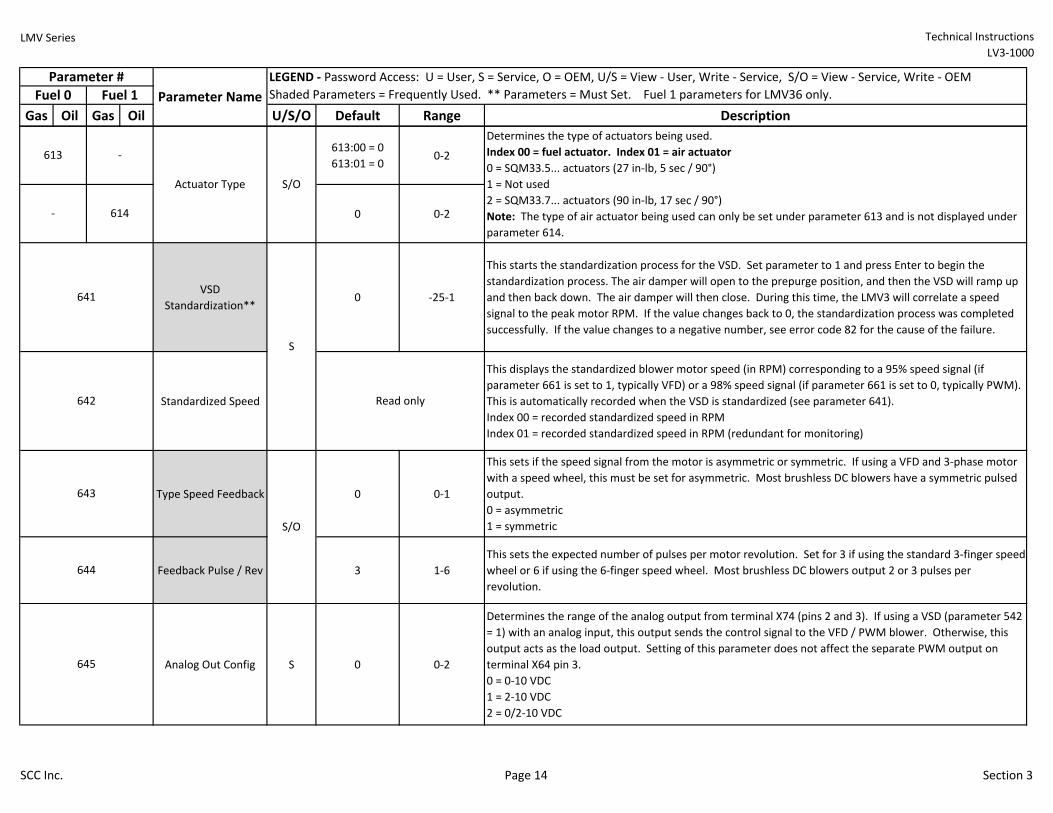
LMV Series Technical Instructions
LV3-1000
Gas Oil Gas Oil U/S/O Default Range Description
Parameter #
Fuel 0 Fuel 1
LEGEND - Password Access: U = User, S = Service, O = OEM, U/S = View - User, Write - Service, S/O = View - Service, Write - OEM
Shaded Parameters = Frequently Used. ** Parameters = Must Set. Fuel 1 parameters for LMV36 only. Parameter Name
613:00 = 0
613:01 = 00-2
0 0-2
VSD
Standardization**0 -25-1
This starts the standardization process for the VSD. Set parameter to 1 and press Enter to begin the
standardization process. The air damper will open to the prepurge position, and then the VSD will ramp up
and then back down. The air damper will then close. During this time, the LMV3 will correlate a speed
signal to the peak motor RPM. If the value changes back to 0, the standardization process was completed
successfully. If the value changes to a negative number, see error code 82 for the cause of the failure.
Standardized Speed
This displays the standardized blower motor speed (in RPM) corresponding to a 95% speed signal (if
parameter 661 is set to 1, typically VFD) or a 98% speed signal (if parameter 661 is set to 0, typically PWM).
This is automatically recorded when the VSD is standardized (see parameter 641).
Index 00 = recorded standardized speed in RPM
Index 01 = recorded standardized speed in RPM (redundant for monitoring)
Type Speed Feedback 0 0-1
This sets if the speed signal from the motor is asymmetric or symmetric. If using a VFD and 3-phase motor
with a speed wheel, this must be set for asymmetric. Most brushless DC blowers have a symmetric pulsed
output.
0 = asymmetric
1 = symmetric
Feedback Pulse / Rev 3 1-6
This sets the expected number of pulses per motor revolution. Set for 3 if using the standard 3-finger speed
wheel or 6 if using the 6-finger speed wheel. Most brushless DC blowers output 2 or 3 pulses per
revolution.
Analog Out Config S 0 0-2
Determines the range of the analog output from terminal X74 (pins 2 and 3). If using a VSD (parameter 542
= 1) with an analog input, this output sends the control signal to the VFD / PWM blower. Otherwise, this
output acts as the load output. Setting of this parameter does not affect the separate PWM output on
terminal X64 pin 3.
0 = 0-10 VDC
1 = 2-10 VDC
2 = 0/2-10 VDC
Determines the type of actuators being used.
Index 00 = fuel actuator. Index 01 = air actuator
0 = SQM33.5... actuators (27 in-lb, 5 sec / 90°)
1 = Not used
2 = SQM33.7... actuators (90 in-lb, 17 sec / 90°)
Note: The type of air actuator being used can only be set under parameter 613 and is not displayed under
parameter 614.
Actuator Type
613 -
641
642
645
S/O
Read only
S/O
643
644
- 614
S
SCC Inc. Page 14 Section 3
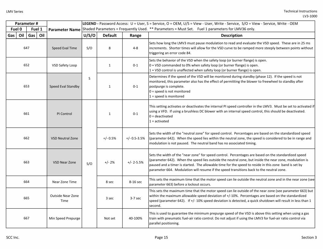
LMV Series Technical Instructions
LV3-1000
Gas Oil Gas Oil U/S/O Default Range Description
Parameter #
Fuel 0 Fuel 1
LEGEND - Password Access: U = User, S = Service, O = OEM, U/S = View - User, Write - Service, S/O = View - Service, Write - OEM
Shaded Parameters = Frequently Used. ** Parameters = Must Set. Fuel 1 parameters for LMV36 only. Parameter Name
Speed Eval Time S/O 8 4-8
Sets how long the LMV3 must pause modulation to read and evaluate the VSD speed. These are in 25 ms
increments. Shorter times will allow for the VSD curve to be ramped more steeply between points without
triggering an error code 84.
VSD Safety Loop 1 0-1
Sets the behavior of the VSD when the safety loop (or burner flange) is open.
0 = VSD commanded to 0% when safety loop (or burner flange) is open.
1 = VSD control is unaffected when safety loop (or burner flange) is open.
Speed Eval Standby 1 0-1
Determines if the speed of the VSD will be monitored during standby (phase 12). If the speed is not
monitored, this parameter also has the effect of permitting the blower to freewheel to standby after
postpurge is complete.
0 = speed is not monitored
1 = speed is monitored
PI Control 1 0-1
This setting activates or deactivates the internal PI speed controller in the LMV3. Must be set to activated if
using a VFD. If using a brushless DC blower with an internal speed control, this should be deactivated.
0 = deactivated
1 = activated
VSD Neutral Zone +/- 0.5% +/- 0.5-3.5%
Sets the width of the "neutral zone" for speed control. Percentages are based on the standardized speed
(parameter 642). When the speed lies within the neutral zone, the speed is considered to be in range and
modulation is not paused. The neutral band has no associated timing.
VSD Near Zone +/- 2% +/- 2-5.5%
Sets the width of the "near zone" for speed control. Percentages are based on the standardized speed
(parameter 642). When the speed lies outside the neutral zone, but inside the near zone, modulation is
paused and a timer is started. The allowable time for the speed to reside in this zone band is set by
parameter 664. Modulation will resume if the speed transitions back to the neutral zone.
Near Zone Time 8 sec 8-16 secThis sets the maximum time that the motor speed can lie outside the neutral zone and in the near zone (see
parameter 663) before a lockout occurs.
Outside Near Zone
Time3 sec 3-7 sec
This sets the maximum time that the motor speed can lie outside of the near zone (see parameter 663) but
within the maximum allowable speed deviation of +/-10%. Percentages are based on the standardized
speed (parameter 642). If +/- 10% speed deviation is detected, a quick shutdown will result in less than 1
second.
Min Speed Prepurge Not set 40-100%
This is used to guarantee the minimum prepurge speed of the VSD is above this setting when using a gas
train with pneumatic fuel-air ratio control. Do not adjust if using the LMV3 for fuel-air ratio control via
parallel positioning.
647
652
653
667
S/O
S
661
662
663
664
665
SCC Inc. Page 15 Section 3
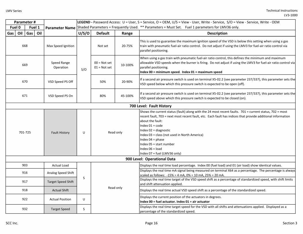
LMV Series Technical Instructions
LV3-1000
Gas Oil Gas Oil U/S/O Default Range Description
Parameter #
Fuel 0 Fuel 1
LEGEND - Password Access: U = User, S = Service, O = OEM, U/S = View - User, Write - Service, S/O = View - Service, Write - OEM
Shaded Parameters = Frequently Used. ** Parameters = Must Set. Fuel 1 parameters for LMV36 only. Parameter Name
Max Speed Ignition Not set 20-75%
This is used to guarantee the maximum ignition speed of the VSD is below this setting when using a gas
train with pneumatic fuel-air ratio control. Do not adjust if using the LMV3 for fuel-air ratio control via
parallel positioning.
Speed Range
Operation
00 = Not set
01 = Not set10-100%
When using a gas train with pneumatic fuel-air ratio control, this defines the minimum and maximum
allowable VSD speeds when the burner is firing. Do not adjust if using the LMV3 for fuel-air ratio control via
parallel positioning.
Index 00 = minimum speed. Index 01 = maximum speed
VSD Speed PS Off 50% 20-90%If a second air pressure switch is used on terminal X5-02.2 (see parameter 237/337), this parameter sets the
VSD speed below which this pressure switch is expected to be open (off).
VSD Speed PS On 80% 45-100%If a second air pressure switch is used on terminal X5-02.2 (see parameter 237/337), this parameter sets the
VSD speed above which this pressure switch is expected to be closed (on).
Fault History U
Shows the current status (fault) along with the 24 most recent faults. 701 = current status, 702 = most
recent fault, 703 = next most recent fault, etc. Each fault has indices that provide additional information
about the fault:
Index 01 = code
Index 02 = diagnostic
Index 03 = class (not used in North America)
Index 04 = phase
Index 05 = start number
Index 06 = load
Index 07 = fuel (LMV36 only)
Actual Load Displays the real time load percentage. Index 00 (fuel load) and 01 (air load) show identical values.
Analog Speed Shift Displays the real time mA signal being measured on terminal X64 as a percentage. The percentage is always
scaled as follows: -15% = 4 mA, 0% = 10 mA, 25% = 20 mA.
Target Speed ShiftDisplays the real time target of the VSD speed shift as a percentage of standardized speed, with shift limits
and shift attenuation applied.
Actual Shift Displays the real time actual VSD speed shift as a percentage of the standardized speed.
Actual Position UDisplays the current position of the actuators in degrees.
Index 00 = fuel actuator. Index 01 = air actuator
Target Speed SDisplays the real time target speed for the VSD with all shifts and attenuations applied. Displayed as a
percentage of the standardized speed.
903
922
918
917
916
668
669
670
671
932
900 Level: Operational Data
700 Level: Fault History
701-725 Read only
Read only
S/O
S
SCC Inc. Page 16 Section 3
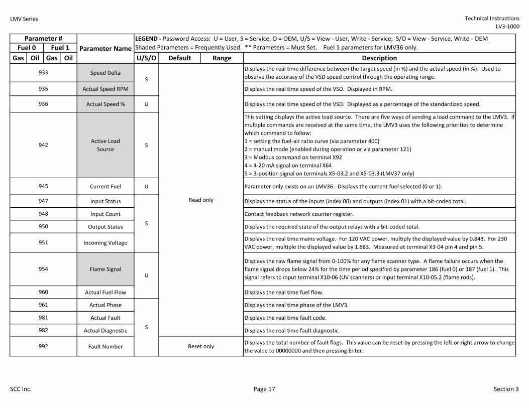
LMV Series Technical Instructions
LV3-1000
Gas Oil Gas Oil U/S/O Default Range Description
Parameter #
Fuel 0 Fuel 1
LEGEND - Password Access: U = User, S = Service, O = OEM, U/S = View - User, Write - Service, S/O = View - Service, Write - OEM
Shaded Parameters = Frequently Used. ** Parameters = Must Set. Fuel 1 parameters for LMV36 only. Parameter Name
Speed DeltaDisplays the real time difference between the target speed (in %) and the actual speed (in %). Used to
observe the accuracy of the VSD speed control through the operating range.
Actual Speed RPM Displays the real time speed of the VSD. Displayed in RPM.
Actual Speed % U Displays the real time speed of the VSD. Displayed as a percentage of the standardized speed.
Active Load
SourceS
This setting displays the active load source. There are five ways of sending a load command to the LMV3. If
multiple commands are received at the same time, the LMV3 uses the following priorities to determine
which command to follow:
1 = setting the fuel-air ratio curve (via parameter 400)
2 = manual mode (enabled during operation or via parameter 121)
3 = Modbus command on terminal X92
4 = 4-20 mA signal on terminal X64
5 = 3-position signal on terminals X5-03.2 and X5-03.3 (LMV37 only)
Current Fuel U Parameter only exists on an LMV36: Displays the current fuel selected (0 or 1).
Input Status Displays the status of the inputs (index 00) and outputs (index 01) with a bit-coded total.
Input Count Contact feedback network counter register.
Output Status Displays the required state of the output relays with a bit-coded total.
Incoming VoltageDisplays the real time mains voltage. For 120 VAC power, multiply the displayed value by 0.843. For 230
VAC power, multiple the displayed value by 1.683. Measured at terminal X3-04 pin 4 and pin 5.
Flame Signal
Displays the raw flame signal from 0-100% for any flame scanner type. A flame failure occurs when the
flame signal drops below 24% for the time period specified by parameter 186 (fuel 0) or 187 (fuel 1). This
signal refers to input terminal X10-06 (UV scanners) or input terminal X10-05.2 (flame rods).
Actual Fuel Flow Displays the real time fuel flow.
Actual Phase Displays the real time phase of the LMV3.
Actual Fault Displays the real time fault code.
Actual Diagnostic Displays the real time fault diagnostic.
Fault NumberDisplays the total number of fault flags. This value can be reset by pressing the left or right arrow to change
the value to 00000000 and then pressing Enter.
S
935
936
942
945
947
948
950
933S
Reset only
951
954
960
961
981
982
992
Read only
S
U
SCC Inc. Page 17 Section 3
LMV Series Technical Instructions
LV3-1000
SCC Inc. Page 18 Section 3
Sequence Diagrams
The Siemens LMV3 BMS can perform a number of different burner sequences based upon how certain parameters are set.
Although there are a number of parameters that affect small aspects of the burner sequence, the main parameters that affect the
sequence are parameters 201 and 301.
These parameters set the framework of the sequence and are based upon the fuel train diagrams in Section 4. The OEM has the
option of selecting one of fourteen different gas trains with their associated sequence diagrams, and one of fifteen different oil
trains with their associated sequence diagrams.
The sequence diagrams illustrate when input and output terminals are expected to be energized or de-energized. A legend on the
bottom of each page describes the various symbols used in the diagrams. The last diagram describes what positions the attached
actuators are expected to achieve at each phase and outlines the method that is used to check the actuators position.
Notes:
1) If parameter 235/335 is set to 2, air pressure switch input X3-02.1 can be de-energized in phases 60-66 without an alarm.
This is only allowed on pneumatic fuel trains.
2) After the main valves open, the high and low pressure switch inputs are ignored for the length of time specified by
parameter 229/269/329/369. This is done so that pressure shocks do not cause erroneous alarms on properly adjusted
automatic reset pressure switches.
3) Parameter 237/277/337/377 sets the function of input X5-02.2.
4) Parameter 210 determines if the alarm output will energize in the event of a start prevention (an alarm in standby). If set to
1 (activated), the LMV3 will wait 5 seconds after receiving a call for heat before going into alarm.
5) Parameter 276/376 defines the phase when the low oil pressure switch input X9-04.2 must be energized. A setting of 1
means the input must be energized in phase 38 (parameter 217 sets the length of time after the beginning of phase 38 that
the input must be energized). A setting of 2 means the input must be energized by the beginning of safety time 1 (phase 40).
LMV Series Technical Instructions
LV3-1000
SCC Inc. Page 19 Section 3
6) On direct ignition oil trains, parameter 281/381 determines the point at which the oil is ignited during the startup sequence.
A setting of 0 means the ignition output X4-02.3 will energize at the beginning of phase 38. A setting of 1 means the ignition
output X4-02.3 will energize at the beginning of phase 22.
7) On heavy oil trains, parameter 286 defines the point in the startup sequence when the start release for heavy oil (input X9-
04.2) must be energized. A setting of 0 means the input only needs to be energized during phase 38. A setting of 1 means
the input must be energized during phases 38-62.
8) If gas valve proving is performed on startup (immediately after phase 30), the actuators will be in prepurge position. If gas
valve proving is performed on shutdown (immediately after phase 62), the actuators will be in the same position as they
were in phase 62. The actuators will not move during valve proving.
9) Actuator position is checked by using one of three methods. The method used depends upon the phase of the sequence.
Position Required to Proceed means that the actuators must achieve and hold a certain position for the sequence to proceed.
Dynamic Position Checking means that the actuator is evaluated by a “time and distance from target” algorithm. The further
the actuator is away from its target position, the less time the actuator is permitted to be in that position. Run-Time Position
Checking means that the actuator is expected to be at a certain point in a certain amount of time (based off of the run-time
of the actuator).
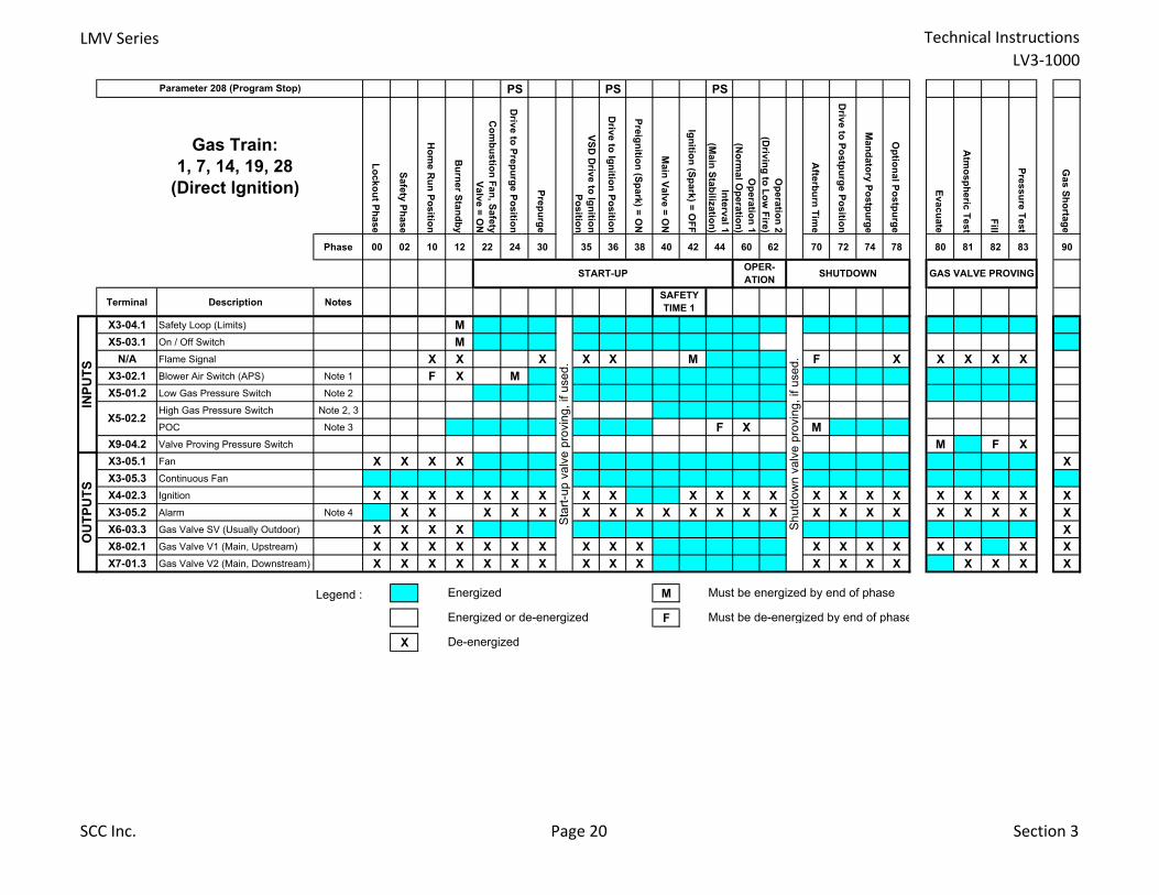
LMV Series Technical Instructions
LV3-1000
PS PS PS
Gas Train:
1, 7, 14, 19, 28
(Direct Ignition)
Lo
cko
ut P
hase
Safe
ty P
hase
Ho
me R
un
Po
sitio
n
Bu
rner S
tan
db
y
Co
mb
ustio
n F
an
, Safe
ty
Valv
e =
ON
Driv
e to
Pre
pu
rge P
ositio
n
Pre
pu
rge
VS
D D
rive to
Ign
ition
Po
sitio
n
Driv
e to
Ign
ition
Po
sitio
n
Pre
ign
ition
(Sp
ark
) = O
N
Main
Valv
e =
ON
Ign
ition
(Sp
ark
) = O
FF
Inte
rval 1
(Main
Sta
biliz
atio
n)
Op
era
tion
1
(No
rmal O
pera
tion
)
Op
era
tion
2
(Driv
ing
to L
ow
Fire
)
Afte
rbu
rn T
ime
Driv
e to
Po
stp
urg
e P
ositio
n
Man
dato
ry P
ostp
urg
e
Op
tion
al P
ostp
urg
e
Evacu
ate
Atm
osp
heric
Test
Fill
Pre
ssu
re T
est
Gas S
ho
rtag
e
Phase 00 02 10 12 22 24 30 35 36 38 40 42 44 60 62 70 72 74 78 80 81 82 83 90
Terminal Description Notes
X3-04.1 Safety Loop (Limits) M
X5-03.1 On / Off Switch M
N/A Flame Signal X X X X X M F X X X X X
X3-02.1 Blower Air Switch (APS) Note 1 F X M
X5-01.2 Low Gas Pressure Switch Note 2
High Gas Pressure Switch Note 2, 3
POC Note 3 F X M
X9-04.2 Valve Proving Pressure Switch M F X
X3-05.1 Fan X X X X X
X3-05.3 Continuous Fan
X4-02.3 Ignition X X X X X X X X X X X X X X X X X X X X X X
X3-05.2 Alarm Note 4 X X X X X X X X X X X X X X X X X X X X X X
X6-03.3 Gas Valve SV (Usually Outdoor) X X X X X
X8-02.1 Gas Valve V1 (Main, Upstream) X X X X X X X X X X X X X X X X X X
X7-01.3 Gas Valve V2 (Main, Downstream) X X X X X X X X X X X X X X X X X X
Legend : M
F
X
OU
TP
UT
SIN
PU
TS
Sh
utd
ow
n v
alv
e p
rovin
g,
if u
se
d.
GAS VALVE PROVINGSTART-UP SHUTDOWNOPER-
ATION
Parameter 208 (Program Stop)
X5-02.2
Energized
Energized or de-energized
De-energized
Must be energized by end of phase
Must be de-energized by end of phase
SAFETY
TIME 1
Sta
rt-u
p v
alv
e p
rovin
g,
if u
se
d.
SCC Inc. Page 20 Section 3
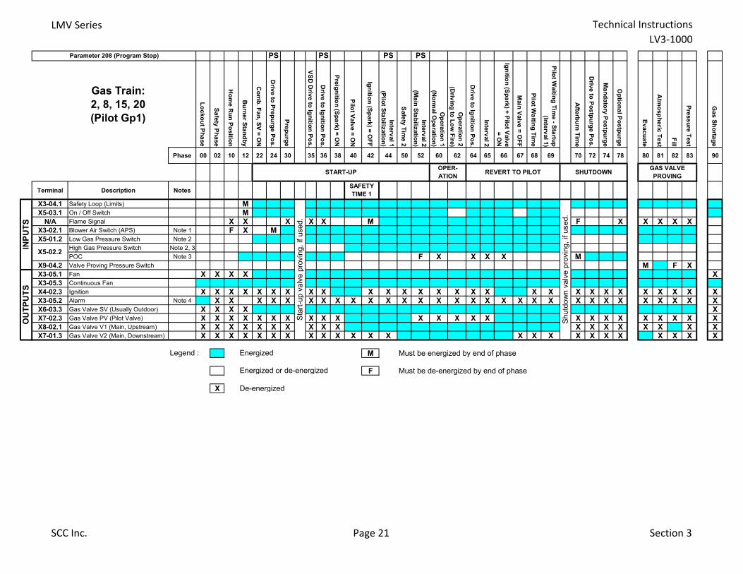
LMV Series Technical Instructions
LV3-1000
PS PS PS PS
Gas Train:
2, 8, 15, 20
(Pilot Gp1)
Lo
ck
ou
t Ph
as
e
Sa
fety
Ph
as
e
Ho
me
Ru
n P
os
ition
Bu
rne
r Sta
nd
by
Co
mb
. Fa
n, S
V =
ON
Driv
e to
Pre
pu
rge
Po
s.
Pre
pu
rge
VS
D D
rive
to Ig
nitio
n P
os
.
Driv
e to
Ign
ition
Po
s.
Pre
ign
ition
(Sp
ark
) = O
N
Pilo
t Va
lve
= O
N
Ign
ition
(Sp
ark
) = O
FF
Inte
rva
l 1
(Pilo
t Sta
biliz
atio
n)
Sa
fety
Tim
e 2
Inte
rva
l 2
(Ma
in S
tab
iliza
tion
)
Op
era
tion
1
(No
rma
l Op
era
tion
)
Op
era
tion
2
(Driv
ing
to L
ow
Fire
)
Driv
e to
Ign
ition
Po
s.
Inte
rva
l 2
Ign
ition
(Sp
ark
) + P
ilot V
alv
e
= O
N
Ma
in V
alv
e =
OF
F
Pilo
t Wa
iting
Tim
e
Pilo
t Wa
iting
Tim
e - S
tartu
p
(Inte
rva
l 1)
Afte
rbu
rn T
ime
Driv
e to
Po
stp
urg
e P
os
.
Ma
nd
ato
ry P
os
tpu
rge
Op
tion
al P
os
tpu
rge
Ev
ac
ua
te
Atm
os
ph
eric
Te
st
Fill
Pre
ss
ure
Te
st
Ga
s S
ho
rtag
e
Phase 00 02 10 12 22 24 30 35 36 38 40 42 44 50 52 60 62 64 65 66 67 68 69 70 72 74 78 80 81 82 83 90
Terminal Description Notes
X3-04.1 Safety Loop (Limits) MX5-03.1 On / Off Switch M
N/A Flame Signal X X X X X M F X X X X XX3-02.1 Blower Air Switch (APS) Note 1 F X MX5-01.2 Low Gas Pressure Switch Note 2
High Gas Pressure Switch Note 2, 3
POC Note 3 F X X X X MX9-04.2 Valve Proving Pressure Switch M F XX3-05.1 Fan X X X X XX3-05.3 Continuous Fan
X4-02.3 Ignition X X X X X X X X X X X X X X X X X X X X X X X X X X X XX3-05.2 Alarm Note 4 X X X X X X X X X X X X X X X X X X X X X X X X X X X X X XX6-03.3 Gas Valve SV (Usually Outdoor) X X X X XX7-02.3 Gas Valve PV (Pilot Valve) X X X X X X X X X X X X X X X X X X X X X X X XX8-02.1 Gas Valve V1 (Main, Upstream) X X X X X X X X X X X X X X X X X XX7-01.3 Gas Valve V2 (Main, Downstream) X X X X X X X X X X X X X X X X X X X X X X X X
Legend : M Must be energized by end of phase
F Must be de-energized by end of phase
X De-energized
Energized or de-energized
START-UP
INP
UT
S
Sta
rt-u
p v
alv
e p
rovin
g,
if u
sed.
GAS VALVE
PROVING
Parameter 208 (Program Stop)
OPER-
ATION SHUTDOWN
Shutd
ow
n v
alv
e p
rovin
g,
if u
sed.
OU
TP
UT
S
Energized
X5-02.2
SAFETY
TIME 1
REVERT TO PILOT
SCC Inc. Page 21 Section 3
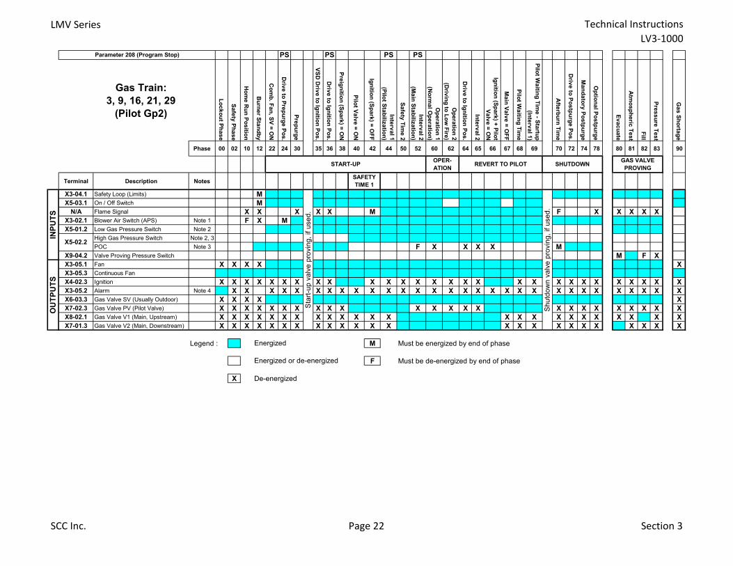
LMV Series Technical Instructions
LV3-1000
PS PS PS PS
Gas Train:
3, 9, 16, 21, 29
(Pilot Gp2)
Lo
ck
ou
t Ph
as
e
Sa
fety
Ph
as
e
Ho
me
Ru
n P
os
ition
Bu
rne
r Sta
nd
by
Co
mb
. Fa
n, S
V =
ON
Driv
e to
Pre
pu
rge
Po
s.
Pre
pu
rge
VS
D D
rive
to Ig
nitio
n P
os
.
Driv
e to
Ign
ition
Po
s.
Pre
ign
ition
(Sp
ark
) = O
N
Pilo
t Va
lve
= O
N
Ign
ition
(Sp
ark
) = O
FF
Inte
rva
l 1
(Pilo
t Sta
biliz
atio
n)
Sa
fety
Tim
e 2
Inte
rva
l 2
(Ma
in S
tab
iliza
tion
)
Op
era
tion
1
(No
rma
l Op
era
tion
)
Op
era
tion
2
(Driv
ing
to L
ow
Fire
)
Driv
e to
Ign
ition
Po
s.
Inte
rva
l 2
Ign
ition
(Sp
ark
) + P
ilot
Va
lve
= O
N
Ma
in V
alv
e =
OF
F
Pilo
t Wa
iting
Tim
e
Pilo
t Wa
iting
Tim
e - S
tartu
p
(Inte
rva
l 1)
Afte
rbu
rn T
ime
Driv
e to
Po
stp
urg
e P
os
.
Ma
nd
ato
ry P
os
tpu
rge
Op
tion
al P
os
tpu
rge
Ev
ac
ua
te
Atm
os
ph
eric
Te
st
Fill
Pre
ss
ure
Te
st
Ga
s S
ho
rtag
e
Phase 00 02 10 12 22 24 30 35 36 38 40 42 44 50 52 60 62 64 65 66 67 68 69 70 72 74 78 80 81 82 83 90
Terminal Description Notes
X3-04.1 Safety Loop (Limits) M
X5-03.1 On / Off Switch M
N/A Flame Signal X X X X X M F X X X X X
X3-02.1 Blower Air Switch (APS) Note 1 F X M
X5-01.2 Low Gas Pressure Switch Note 2
High Gas Pressure Switch Note 2, 3
POC Note 3 F X X X X M
X9-04.2 Valve Proving Pressure Switch M F X
X3-05.1 Fan X X X X X
X3-05.3 Continuous Fan
X4-02.3 Ignition X X X X X X X X X X X X X X X X X X X X X X X X X X X X
X3-05.2 Alarm Note 4 X X X X X X X X X X X X X X X X X X X X X X X X X X X X X X
X6-03.3 Gas Valve SV (Usually Outdoor) X X X X X
X7-02.3 Gas Valve PV (Pilot Valve) X X X X X X X X X X X X X X X X X X X X X X X X
X8-02.1 Gas Valve V1 (Main, Upstream) X X X X X X X X X X X X X X X X X X X X X X X X
X7-01.3 Gas Valve V2 (Main, Downstream) X X X X X X X X X X X X X X X X X X X X X X X X
Legend : M Must be energized by end of phase
F Must be de-energized by end of phase
X De-energized
GAS VALVE
PROVING
X5-02.2
Parameter 208 (Program Stop)
START-UPOPER-
ATION REVERT TO PILOT SHUTDOWN
Energized or de-energized
SAFETY
TIME 1
INP
UT
S
Sta
rt-u
p v
alv
e p
rovin
g,
if u
se
d.
Sh
utd
ow
n v
alv
e p
rovin
g,
if u
se
d.
OU
TP
UT
S
Energized
SCC Inc. Page 22 Section 3
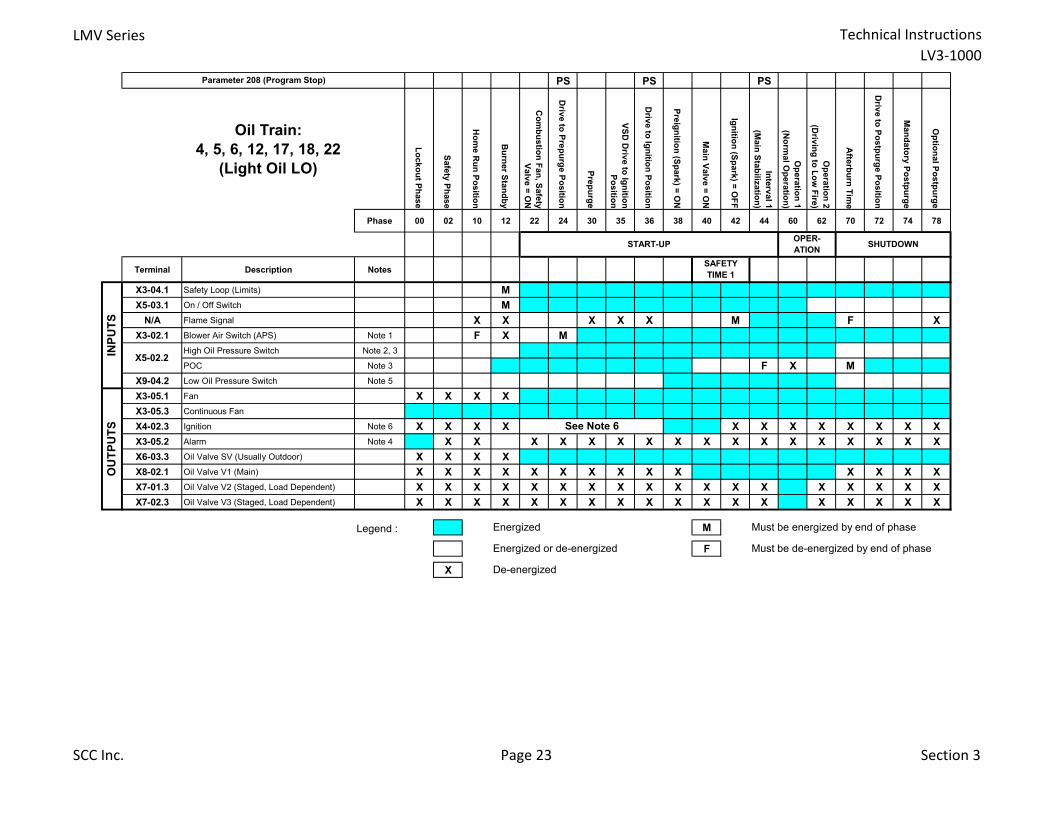
LMV Series Technical Instructions
LV3-1000
PS PS PS
Oil Train:
4, 5, 6, 12, 17, 18, 22
(Light Oil LO)
Lo
cko
ut P
hase
Safe
ty P
hase
Ho
me R
un
Po
sitio
n
Bu
rner S
tan
db
y
Co
mb
ustio
n F
an
, Safe
ty
Valv
e =
ON
Driv
e to
Pre
pu
rge P
ositio
n
Pre
pu
rge
VS
D D
rive to
Ign
ition
Po
sitio
n
Driv
e to
Ign
ition
Po
sitio
n
Pre
ign
ition
(Sp
ark
) = O
N
Main
Valv
e =
ON
Ign
ition
(Sp
ark
) = O
FF
Inte
rval 1
(Main
Sta
biliz
atio
n)
Op
era
tion
1
(No
rmal O
pera
tion
)
Op
era
tion
2
(Driv
ing
to L
ow
Fire
)
Afte
rbu
rn T
ime
Driv
e to
Po
stp
urg
e P
ositio
n
Man
dato
ry P
ostp
urg
e
Op
tion
al P
ostp
urg
e
Phase 00 02 10 12 22 24 30 35 36 38 40 42 44 60 62 70 72 74 78
Terminal Description Notes
X3-04.1 Safety Loop (Limits) M
X5-03.1 On / Off Switch M
N/A Flame Signal X X X X X M F X
X3-02.1 Blower Air Switch (APS) Note 1 F X M
High Oil Pressure Switch Note 2, 3
POC Note 3 F X M
X9-04.2 Low Oil Pressure Switch Note 5
X3-05.1 Fan X X X X
X3-05.3 Continuous Fan
X4-02.3 Ignition Note 6 X X X X X X X X X X X X
X3-05.2 Alarm Note 4 X X X X X X X X X X X X X X X X X
X6-03.3 Oil Valve SV (Usually Outdoor) X X X X
X8-02.1 Oil Valve V1 (Main) X X X X X X X X X X X X X X
X7-01.3 Oil Valve V2 (Staged, Load Dependent) X X X X X X X X X X X X X X X X X X
X7-02.3 Oil Valve V3 (Staged, Load Dependent) X X X X X X X X X X X X X X X X X X
Legend : M
F
X
INP
UT
SO
UT
PU
TS
Parameter 208 (Program Stop)
START-UPOPER-
ATION SHUTDOWN
X5-02.2
Must be energized by end of phase
Energized or de-energized Must be de-energized by end of phase
De-energized
See Note 6
SAFETY
TIME 1
Energized
SCC Inc. Page 23 Section 3
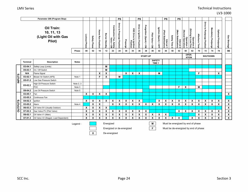
LMV Series Technical Instructions
LV3-1000
PS PS PS PS
Oil Train:
10, 11, 13
(Light Oil with Gas
Pilot)
Lo
ck
ou
t Ph
as
e
Sa
fety
Ph
as
e
Ho
me
Ru
n P
os
ition
Bu
rne
r Sta
nd
by
Co
mb
us
tion
Fa
n, S
afe
ty
Va
lve
= O
N
Driv
e to
Pre
pu
rge
Po
sitio
n
Pre
pu
rge
VS
D D
rive
to Ig
nitio
n
Po
sitio
n
Driv
e to
Ign
ition
Po
sitio
n
Pre
ign
ition
(Sp
ark
) = O
N
Pilo
t Va
lve
= O
N
Ign
ition
(Sp
ark
) = O
FF
Inte
rva
l 1
(Pilo
t Sta
biliz
atio
n)
Sa
fety
Tim
e 2
Inte
rva
l 2
(Ma
in S
tab
iliza
tion
)
Op
era
tion
1
(No
rma
l Op
era
tion
)
Op
era
tion
2
(Driv
ing
to L
ow
Fire
)
Afte
rbu
rn T
ime
Driv
e to
Po
stp
urg
e P
os
ition
Ma
nd
ato
ry P
os
tpu
rge
Op
tion
al P
os
tpu
rge
Ga
s S
ho
rtag
e
Phase 00 02 10 12 22 24 30 35 36 38 40 42 44 50 52 60 62 70 72 74 78 90
Terminal Description Notes
X3-04.1 Safety Loop (Limits) M
X5-03.1 On / Off Switch M
N/A Flame Signal X X X X X M F X
X3-02.1 Blower Air Switch (APS) Note 1 F X M
X5-01.2 Low Gas Pressure Switch
High Oil Pressure Switch Note 2, 3
POC Note 3 F X M
X9-04.2 Low Oil Pressure Switch Note 5
X3-05.1 Fan X X X X X
X3-05.3 Continuous Fan
X4-02.3 Ignition X X X X X X X X X X X X X X X X X X X X
X3-05.2 Alarm Note 4 X X X X X X X X X X X X X X X X X X X X
X6-03.3 Oil Valve SV (Usually Outdoor) X X X X X
X7-02.3 Gas Valve PV (Pilot Valve) X X X X X X X X X X X X X X X X X X
X8-02.1 Oil Valve V1 (Main) X X X X X X X X X X X X X X X X X X
X7-01.3 Oil Valve V2 (Staged, Load Dependent) X X X X X X X X X X X X X X X X X X X X X
Legend : M
F
X
INP
UT
S
X5-02.2
OU
TP
UT
S
Energized Must be energized by end of phase
Energized or de-energized Must be de-energized by end of phase
De-energized
START-UP
Parameter 208 (Program Stop)
OPER-
ATION SHUTDOWN
SAFETY
TIME 1
SCC Inc. Page 24 Section 3
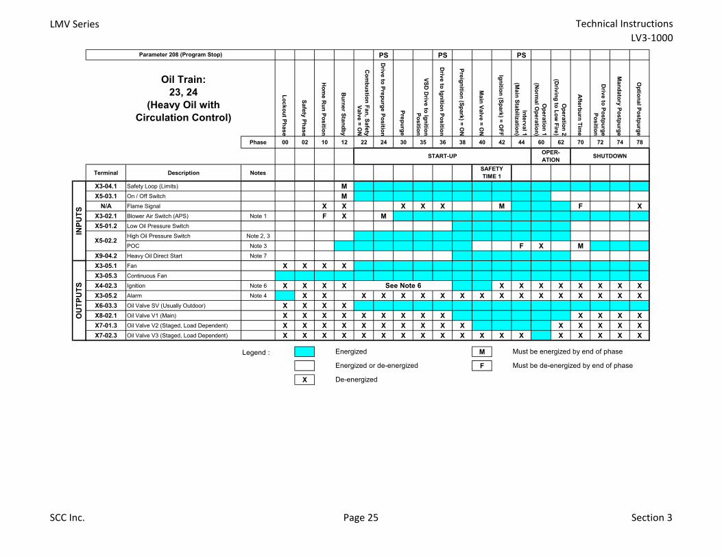
LMV Series Technical Instructions
LV3-1000
PS PS PS
Oil Train:
23, 24
(Heavy Oil with
Circulation Control)
Lo
ck
ou
t Ph
as
e
Sa
fety
Ph
as
e
Ho
me
Ru
n P
os
ition
Bu
rne
r Sta
nd
by
Co
mb
us
tion
Fa
n, S
afe
ty
Va
lve
= O
N
Driv
e to
Pre
pu
rge
Po
sitio
n
Pre
pu
rge
VS
D D
rive
to Ig
nitio
n
Po
sitio
n
Driv
e to
Ign
ition
Po
sitio
n
Pre
ign
ition
(Sp
ark
) = O
N
Ma
in V
alv
e =
ON
Ign
ition
(Sp
ark
) = O
FF
Inte
rva
l 1
(Ma
in S
tab
iliza
tion
)
Op
era
tion
1
(No
rma
l Op
era
tion
)
Op
era
tion
2
(Driv
ing
to L
ow
Fire
)
Afte
rbu
rn T
ime
Driv
e to
Po
stp
urg
e
Po
sitio
n
Ma
nd
ato
ry P
os
tpu
rge
Op
tion
al P
os
tpu
rge
Phase 00 02 10 12 22 24 30 35 36 38 40 42 44 60 62 70 72 74 78
Terminal Description Notes
X3-04.1 Safety Loop (Limits) M
X5-03.1 On / Off Switch M
N/A Flame Signal X X X X X M F X
X3-02.1 Blower Air Switch (APS) Note 1 F X M
X5-01.2 Low Oil Pressure Switch
High Oil Pressure Switch Note 2, 3
POC Note 3 F X M
X9-04.2 Heavy Oil Direct Start Note 7
X3-05.1 Fan X X X X
X3-05.3 Continuous Fan
X4-02.3 Ignition Note 6 X X X X X X X X X X X X
X3-05.2 Alarm Note 4 X X X X X X X X X X X X X X X X X
X6-03.3 Oil Valve SV (Usually Outdoor) X X X X
X8-02.1 Oil Valve V1 (Main) X X X X X X X X X X X X X
X7-01.3 Oil Valve V2 (Staged, Load Dependent) X X X X X X X X X X X X X X X
X7-02.3 Oil Valve V3 (Staged, Load Dependent) X X X X X X X X X X X X X X X X X X
Legend : M
F
X De-energized
Parameter 208 (Program Stop)
START-UPOPER-
ATION SHUTDOWN
SAFETY
TIME 1
Energized or de-energized Must be de-energized by end of phase
INP
UT
S
X5-02.2
OU
TP
UT
S See Note 6
Energized Must be energized by end of phase
SCC Inc. Page 25 Section 3
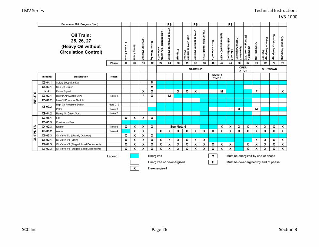
LMV Series Technical Instructions
LV3-1000
PS PS PS
Oil Train:
25, 26, 27
(Heavy Oil without
Circulation Control)
Lo
ck
ou
t Ph
as
e
Sa
fety
Ph
as
e
Ho
me
Ru
n P
os
ition
Bu
rne
r Sta
nd
by
Co
mb
us
tion
Fa
n, S
afe
ty
Va
lve
= O
N
Driv
e to
Pre
pu
rge
Po
sitio
n
Pre
pu
rge
VS
D D
rive
to Ig
nitio
n
Po
sitio
n
Driv
e to
Ign
ition
Po
sitio
n
Pre
ign
ition
(Sp
ark
) = O
N
Ma
in V
alv
e =
ON
Ign
ition
(Sp
ark
) = O
FF
Inte
rva
l 1
(Ma
in S
tab
iliza
tion
)
Op
era
tion
1
(No
rma
l Op
era
tion
)
Op
era
tion
2
(Driv
ing
to L
ow
Fire
)
Afte
rbu
rn T
ime
Driv
e to
Po
stp
urg
e
Po
sitio
n
Ma
nd
ato
ry P
os
tpu
rge
Op
tion
al P
os
tpu
rge
Phase 00 02 10 12 22 24 30 35 36 38 40 42 44 60 62 70 72 74 78
Terminal Description Notes
X3-04.1 Safety Loop (Limits) M
X5-03.1 On / Off Switch M
N/A Flame Signal X X X X X M F X
X3-02.1 Blower Air Switch (APS) Note 1 F X M
X5-01.2 Low Oil Pressure Switch
High Oil Pressure Switch Note 2, 3
POC Note 3 F X M
X9-04.2 Heavy Oil Direct Start Note 7
X3-05.1 Fan X X X X
X3-05.3 Continuous Fan
X4-02.3 Ignition Note 6 X X X X X X X X X X X X
X3-05.2 Alarm Note 4 X X X X X X X X X X X X X X X X X
X6-03.3 Oil Valve SV (Usually Outdoor) X X X X
X8-02.1 Oil Valve V1 (Main) X X X X X X X X X X X X X X
X7-01.3 Oil Valve V2 (Staged, Load Dependent) X X X X X X X X X X X X X X X X X X
X7-02.3 Oil Valve V3 (Staged, Load Dependent) X X X X X X X X X X X X X X X X X X
Legend : M
F
X
Parameter 208 (Program Stop)
START-UPOPER-
ATION SHUTDOWN
SAFETY
TIME 1
INP
UT
S
X5-02.2
De-energized
OU
TP
UT
S See Note 6
Energized Must be energized by end of phase
Energized or de-energized Must be de-energized by end of phase
SCC Inc. Page 26 Section 3
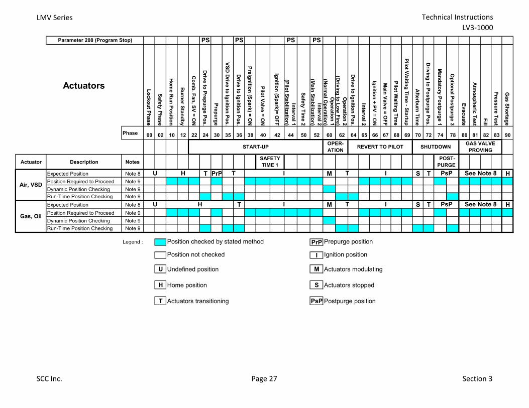
LMV Series Technical Instructions
LV3-1000
PS PS PS PS
Actuators Lo
ck
ou
t Ph
as
e
Sa
fety
Ph
as
e
Ho
me
Ru
n P
os
ition
Bu
rne
r Sta
nd
by
Co
mb
. Fa
n, S
V =
ON
Driv
e to
Pre
pu
rge
Po
s.
Pre
pu
rge
VS
D D
rive
to Ig
nitio
n P
os
.
Driv
e to
Ign
ition
Po
s.
Pre
ign
ition
(Sp
ark
) = O
N
Pilo
t Va
lve
= O
N
Ign
ition
(Sp
ark
)= O
FF
Inte
rva
l 1
(Pilo
t Sta
biliz
atio
n)
Sa
fety
Tim
e 2
Inte
rva
l 2
(Ma
in S
tab
iliza
tion
)
Op
era
tion
1
(No
rma
l Op
era
tion
)
Op
era
tion
2
(Driv
ing
to L
ow
Fire
)
Driv
e to
Ign
ition
Po
s.
Inte
rva
l 2
Ign
ition
+ P
V =
ON
Ma
in V
alv
e =
OF
F
Pilo
t Wa
iting
Tim
e
Pilo
t Wa
iting
Tim
e - S
tartu
p
Afte
rbu
rn T
ime
Driv
ing
to P
os
tpu
rge
Po
s.
Ma
nd
ato
ry P
os
tpu
rge
1
Op
tion
al P
os
tpu
rge
3
Ev
ac
ua
te
Atm
os
ph
eric
Te
st
Fill
Pre
ss
ure
Te
st
Ga
s S
ho
rtag
e
Phase 00 02 10 12 22 24 30 35 36 38 40 42 44 50 52 60 62 64 65 66 67 68 69 70 72 74 78 80 81 82 83 90
Actuator Description Notes
Expected Position Note 8 T PrP M S T H
Position Required to Proceed Note 9
Dynamic Position Checking Note 9
Run-Time Position Checking Note 9
Expected Position Note 8 T M S T H
Position Required to Proceed Note 9
Dynamic Position Checking Note 9
Run-Time Position Checking Note 9
Legend : Position checked by stated method PrP Prepurge position
Position not checked I Ignition position
U Undefined position M Actuators modulating
H Home position S Actuators stopped
T Actuators transitioning PsP Postpurge position
Gas, Oil
U I PsP See Note 8H
Air, VSD
OPER-
ATION SHUTDOWN
GAS VALVE
PROVING
See Note 8I PsP
POST-
PURGE
T
Parameter 208 (Program Stop)
REVERT TO PILOT
IT
T I
HU
START-UP
SAFETY
TIME 1
SCC Inc. Page 27 Section 3

Technical Instructions LMV Series
Document No. LV3-1000
Section 3 Page 28 SCC Inc.
Intentionally Left Blank
Section 1 Overview
Section 2 Wiring
Section 3 Parameters
Section 4 Commissioning
Section 5 VSD
Section 6 Troubleshooting
Section 7 Modbus
Section 8 ACS410
Appendix A Application Guide

Section 1 Overview
Section 2 Wiring
Section 3 Parameters
Section 4 Commissioning
Section 5 VSD
Section 6 Troubleshooting
Section 7 Modbus
Section 8 ACS410
Appendix A Application Guide
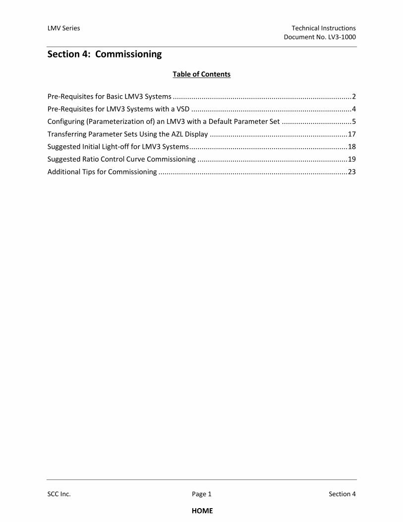
LMV Series Technical Instructions
Document No. LV3-1000
SCC Inc. Page 1 Section 4
Section 4: Commissioning
Table of Contents
Pre-Requisites for Basic LMV3 Systems ....................................................................................... 2
Pre-Requisites for LMV3 Systems with a VSD .............................................................................. 4
Configuring (Parameterization of) an LMV3 with a Default Parameter Set .................................. 5
Transferring Parameter Sets Using the AZL Display ................................................................... 17
Suggested Initial Light-off for LMV3 Systems ............................................................................. 18
Suggested Ratio Control Curve Commissioning ......................................................................... 19
Additional Tips for Commissioning ............................................................................................ 23
Technical Instructions LMV Series
Document No. LV3-1000
Section 4 Page 2 SCC Inc.
Before the LMV3 can be commissioned, certain pre-requisites must be met for the LMV3 control, the
burner, the boiler, and the boiler room. Experience has shown that if the points below are addressed
properly, commissioning will be safe, timely, and trouble-free.
Pre-Requisites for Basic LMV3 Systems
1. Burner / boiler must be in "good" condition. Burner firing head must be correct for the boiler
and the firing head must not be cracked, melted, or otherwise damaged. Other items to check
include:
a. Flame scanner tube must sight pilot and main flame correctly.
b. Refractory should not interfere with the flame scanner sighting or the flame path of the
burner.
c. For fire tube boilers, the flame should not impinge on the Morrison tube.
2. All LMV3 components (base unit, actuators, flame scanners, etc.) are mounted properly.
Particular attention should be paid to the following:
a. Actuator shaft couplings must accomplish the following:
i. Compensate for both angular and parallel shaft misalignment generated by the
mounting bracket.
ii. Have little or no backlash.
iii. Be robust enough to absorb the stall torque of the actuator without damage.
Solid (rigid) shaft couplings are not acceptable in most applications. Clamp-type
couplings that have a D-shape are preferred since these will not damage the actuator
shaft and do provide positive engagement. In linkage-less applications, actuator
couplings should be considered to be safety-related components.
NOTE: Do not couple actuator to valve / damper shaft until the direction of rotation
for the actuator is set, and the LMV3 alarm is reset. This is outlined later in the
commissioning section.
b. Actuator brackets must be rigid enough so that they do not amplify burner vibration
(diving board effect) or distort significantly when the actuator is applying maximum
torque to the valve / damper shaft.
c. When actuator is installed and coupled, ensure that all mounting hardware is tightened
adequately, and some method of thread locking is employed on the mounting hardware
(except for the coupling hardware).
LMV Series Technical Instructions
Document No. LV3-1000
SCC Inc. Page 3 Section 4
d. Ensure environmental conditions (temperature, vibration, moisture, etc.) are not
exceeded.
3. Ensure that all wiring is per the applicable wiring diagram and also meets applicable local and
national codes. Particular attention should be paid to the following:
a. If a step-down control transformer is the source of 120 VAC power for the LMV3, the
ground and neutral should be bonded (connected) on the transformer.
b. Voltage supply to a 120 VAC LMV3 must be between 102 and 132 VAC, 47-63 Hz.
Waveform must be a full sine wave.
4. Fuel (gas) supply must be adequate to support high fire operation and fuel (gas) train must be
sized correctly.
a. Fuel (gas) pressure before the firing rate control valve must be correct, stable and
repeatable at all firing rates and must not vary when other fuel (gas) burning appliances
(other boilers in the building) are being operated.
b. The fuel (gas) pressure regulator on the burner being commissioned should not be fully
open at high fire and should not be bouncing off the seat at low fire. Fuel regulator
must be sized properly, and have adequate turndown capability.
5. A temporary stack gas analyzer that has been calibrated and at a minimum reads O2 (%) and CO
(ppm) must be used for setting combustion.
6. Knowledge of what fuel flow represents high fire of the burner / boiler combination and also the
turndown of the burner / boiler combination. This can typically be found on the burner / boiler
nameplate.
7. A method of determining firing rate (fuel flow within +/- 5%) should be used. This, in
combination with knowledge of high fire and turndown, is used to set the fuel flow on each
curve point. An Excel spreadsheet is available for this purpose.
8. For steam boilers, the feedwater supply must be adequate to support high fire operation.
Feedwater controls must be working properly.
9. The load on the boiler must be adequate so that a burner / boiler combination can be run at
high fire for a minimum of 5 minutes.

Technical Instructions LMV Series
Document No. LV3-1000
Section 4 Page 4 SCC Inc.
Pre-Requisites for LMV3 Systems with a VSD
1. All pre-requisites of the Basic LMV3 system apply.
2. For VFD equipped burners, the blower motor speed sensor and speed wheel must be installed
correctly.
3. Proper grounding between the LMV3, the VSD, and the motor must be installed. See Section 2
(Wiring) for more details.
4. For VFD equipped burners, VFD parameters must be set correctly to be compatible with both
the LMV3 and the blower motor. See Section 5 (VSD) for more details. Particular attention
should be paid to the following:
a. Analog signal configuration. Both the LMV3 and VFD must be configured for a 0-10 VDC
signal.
b. Ramp rates between the LMV3 and the VFD must be compatible. In general, ramp rates
of the VFD should be 10 seconds less than the LMV3.
c. VFD must be set up as a slave unit for a 0-10 VDC signal. Damping, dead band, and PID
functions must be disabled.
d. The frequency (Hz) output of the drive must be directly proportional to the analog input
signal.
e. Acceleration / deceleration curves must be linear instead of “S-shaped”.
f. Ramp settings must be ramp up / ramp down instead of ramp up / coast down.
g. Any type of damping or stall prevention in the VFD should be deactivated.
5. LMV3 / VSD combination must be “Standardized” before operation. See Section 5 (VSD) for
more details.
a. Verify that the air damper opens to pre-purge position before the blower is energized
for standardization.
LMV Series Technical Instructions
Document No. LV3-1000
SCC Inc. Page 5 Section 4
Configuring (Parameterization of) an LMV3 with a Default Parameter Set
The procedure below assumes an LMV3 with a default parameter set. If the LMV3 is mounted to a
burner / boiler, the OEM(s) may have already changed the parameters from the default setting and
parameterized the LMV3 for the application.
Section 3 (Parameters) gives a detailed explanation of all of the parameters in the LMV3, as well as
highlights which parameters must be set (marked with a double asterisk **) and which parameters are
frequently used (shaded).
This procedure gives a general guideline of what parameters need to be set to get an LMV3 running on a
typical burner / boiler. Every burner is different, so it is likely that every burner will need a somewhat
unique parameter set to run correctly.
When an LMV3 with a default parameter set is powered up and wired correctly, it will state "OFF UPr".
This means that the unit is in standby, and has not yet been fully commissioned.
1. Log in at the OEM password level. To do so, hold down the F and A buttons together until
“CodE” is displayed. Type in the OEM password and press Enter to log in. From the factory, the
OEM password for the LMV3 is "EntrY".
2. Set the Burner ID via parameter 113. The Burner ID is a unique number which matches the
burner to the parameter set in the LMV3. Typically, the serial number of the burner is used as
the Burner ID.
3. Set the fuel train(s) via parameter 201 (fuel 0) and parameter 301 (fuel 1 – LMV36 only). Both
fuel 0 and fuel 1 may be set for either a gas train or an oil train, so it is possible to be
programmed for two gas trains, two oil trains, or one gas train and one oil train on an LMV36.
See pages 6-13 for fuel train information. This procedure is continued on page 14. Option 3
(Gp2 mod) is typical for gas piloted gas burners and option 10 (Lo Gp mod) is typical for gas
piloted oil burners.
NOTE: Heavy oil fuel trains (options 23-27) are not discussed in this document. If assistance is
required on a heavy oil fuel train, contact SCC Inc.

Technical Instructions LMV Series
Document No. LV3-1000
Section 4 Page 6 SCC Inc.
Modulating Gas - Direct Spark Ignition
(Fuel Train Options 1, 7, 14, 19, 28)
Legend:
SV = Safety valve (optional, outside building) V1 = Upstream gas valve (main)
PS = Pressure switch V2 = Downstream gas valve (main)
VP = Valve proving
Notes:
1. Fuel actuator not used with options 7, 14, or 28
2. A single shutoff valve can be used where allowed by code
3. The SKP25 (on valve V2) is typically replaced by an SKP55/75 for pneumatically linked gas trains
4. The low gas pressure switch must be installed downstream of the SKP25 for CSA B149.3 compliance
Op
era
tin
g M
od
e
Pa
ram
ete
r 2
01
(fu
el
0)
or
30
1 (
fue
l 1
)
Fuel Train
Fu
el
Act
ua
tor
Air
Act
ua
tor
VS
D S
pe
ed
Fe
ed
ba
ck (
if a
ctiv
ate
d)
Description
1 G mod • • • Modulating gas, direct ignition, electronically linked fuel-to-air ratio
7 G mod pneu • Modulating gas, direct ignition, pneumatically linked fuel-to-air ratio
14 G mod pneuModulating gas, direct ignition, pneumatically linked fuel-to-air ratio, no
actuators
19 G mod • • Modulating gas, direct ignition, electronically linked fuel-to-air ratio
28 G mod mech • • Modulating gas, direct ignition, mechanically linked fuel-to-air ratio
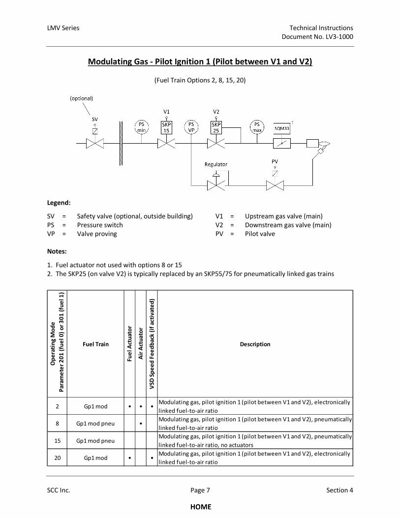
LMV Series Technical Instructions
Document No. LV3-1000
SCC Inc. Page 7 Section 4
Modulating Gas - Pilot Ignition 1 (Pilot between V1 and V2)
(Fuel Train Options 2, 8, 15, 20)
Legend:
SV = Safety valve (optional, outside building) V1 = Upstream gas valve (main)
PS = Pressure switch V2 = Downstream gas valve (main)
VP = Valve proving PV = Pilot valve
Notes:
1. Fuel actuator not used with options 8 or 15
2. The SKP25 (on valve V2) is typically replaced by an SKP55/75 for pneumatically linked gas trains
Op
era
tin
g M
od
e
Pa
ram
ete
r 2
01
(fu
el
0)
or
30
1 (
fue
l 1
)
Fuel Train
Fu
el
Act
ua
tor
Air
Act
ua
tor
VS
D S
pe
ed
Fe
ed
ba
ck (
if a
ctiv
ate
d)
Description
2 Gp1 mod • • •Modulating gas, pilot ignition 1 (pilot between V1 and V2), electronically
linked fuel-to-air ratio
8 Gp1 mod pneu •Modulating gas, pilot ignition 1 (pilot between V1 and V2), pneumatically
linked fuel-to-air ratio
15 Gp1 mod pneuModulating gas, pilot ignition 1 (pilot between V1 and V2), pneumatically
linked fuel-to-air ratio, no actuators
20 Gp1 mod • •Modulating gas, pilot ignition 1 (pilot between V1 and V2), electronically
linked fuel-to-air ratio
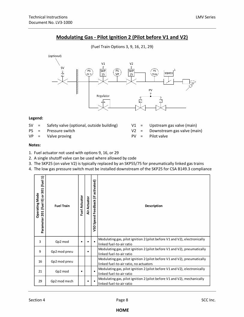
Technical Instructions LMV Series
Document No. LV3-1000
Section 4 Page 8 SCC Inc.
Modulating Gas - Pilot Ignition 2 (Pilot before V1 and V2)
(Fuel Train Options 3, 9, 16, 21, 29)
Legend:
SV = Safety valve (optional, outside building) V1 = Upstream gas valve (main)
PS = Pressure switch V2 = Downstream gas valve (main)
VP = Valve proving PV = Pilot valve
Notes:
1. Fuel actuator not used with options 9, 16, or 29
2. A single shutoff valve can be used where allowed by code
3. The SKP25 (on valve V2) is typically replaced by an SKP55/75 for pneumatically linked gas trains
4. The low gas pressure switch must be installed downstream of the SKP25 for CSA B149.3 compliance
Op
era
tin
g M
od
e
Pa
ram
ete
r 2
01
(fu
el
0)
or
30
1 (
fue
l 1
)
Fuel Train
Fu
el
Act
ua
tor
Air
Act
ua
tor
VS
D S
pe
ed
Fe
ed
ba
ck (
if a
ctiv
ate
d)
Description
3 Gp2 mod • • •Modulating gas, pilot ignition 2 (pilot before V1 and V2), electronically
linked fuel-to-air ratio
9 Gp2 mod pneu •Modulating gas, pilot ignition 2 (pilot before V1 and V2), pneumatically
linked fuel-to-air ratio
16 Gp2 mod pneuModulating gas, pilot ignition 2 (pilot before V1 and V2), pneumatically
linked fuel-to-air ratio, no actuators
21 Gp2 mod • •Modulating gas, pilot ignition 2 (pilot before V1 and V2), electronically
linked fuel-to-air ratio
29 Gp2 mod mech • •Modulating gas, pilot ignition 2 (pilot before V1 and V2), mechanically
linked fuel-to-air ratio
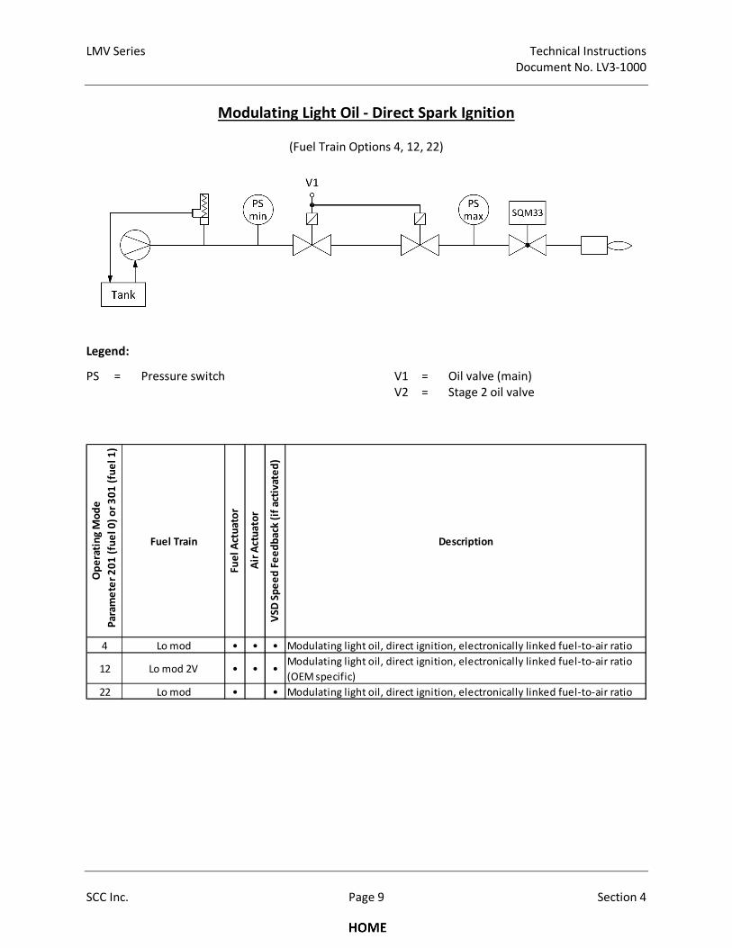
LMV Series Technical Instructions
Document No. LV3-1000
SCC Inc. Page 9 Section 4
Modulating Light Oil - Direct Spark Ignition
(Fuel Train Options 4, 12, 22)
Legend:
PS = Pressure switch V1 = Oil valve (main)
V2 = Stage 2 oil valve
Op
era
tin
g M
od
e
Pa
ram
ete
r 2
01
(fu
el
0)
or
30
1 (
fue
l 1
)
Fuel Train
Fu
el
Act
ua
tor
Air
Act
ua
tor
VS
D S
pe
ed
Fe
ed
ba
ck (
if a
ctiv
ate
d)
Description
4 Lo mod • • • Modulating light oil, direct ignition, electronically linked fuel-to-air ratio
12 Lo mod 2V • • •Modulating light oil, direct ignition, electronically linked fuel-to-air ratio
(OEM specific)
22 Lo mod • • Modulating light oil, direct ignition, electronically linked fuel-to-air ratio
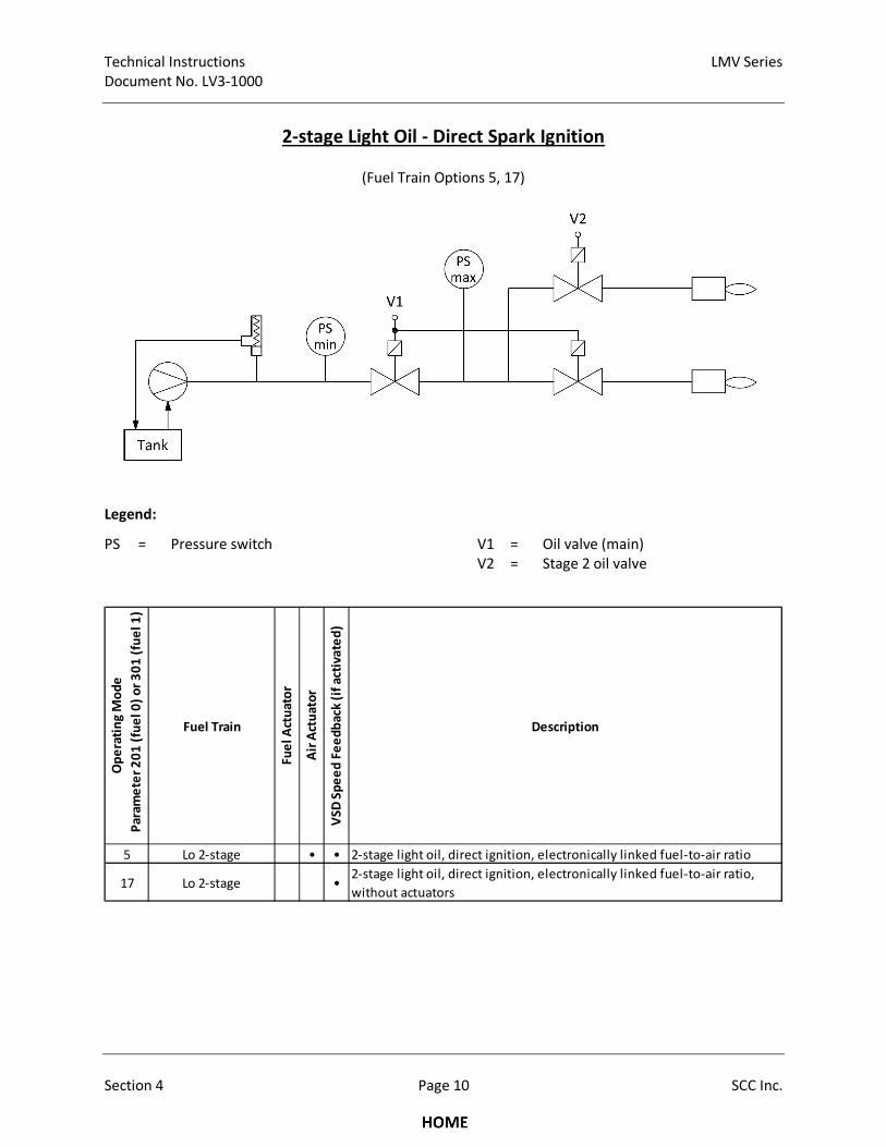
Technical Instructions LMV Series
Document No. LV3-1000
Section 4 Page 10 SCC Inc.
2-stage Light Oil - Direct Spark Ignition
(Fuel Train Options 5, 17)
Legend:
PS = Pressure switch V1 = Oil valve (main)
V2 = Stage 2 oil valve
Op
era
tin
g M
od
e
Pa
ram
ete
r 2
01
(fu
el
0)
or
30
1 (
fue
l 1
)
Fuel Train
Fu
el
Act
ua
tor
Air
Act
ua
tor
VS
D S
pe
ed
Fe
ed
ba
ck (
if a
ctiv
ate
d)
Description
5 Lo 2-stage • • 2-stage light oil, direct ignition, electronically linked fuel-to-air ratio
17 Lo 2-stage •2-stage light oil, direct ignition, electronically linked fuel-to-air ratio,
without actuators
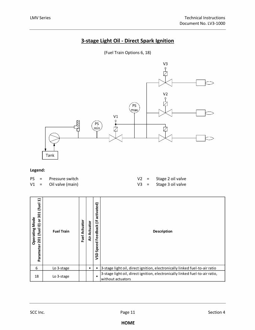
LMV Series Technical Instructions
Document No. LV3-1000
SCC Inc. Page 11 Section 4
3-stage Light Oil - Direct Spark Ignition
(Fuel Train Options 6, 18)
Legend:
PS = Pressure switch V2 = Stage 2 oil valve
V1 = Oil valve (main) V3 = Stage 3 oil valve
Op
era
tin
g M
od
e
Pa
ram
ete
r 2
01
(fu
el
0)
or
30
1 (
fue
l 1
)
Fuel Train
Fu
el
Act
ua
tor
Air
Act
ua
tor
VS
D S
pe
ed
Fe
ed
ba
ck (
if a
ctiv
ate
d)
Description
6 Lo 3-stage • • 3-stage light oil, direct ignition, electronically linked fuel-to-air ratio
18 Lo 3-stage •3-stage light oil, direct ignition, electronically linked fuel-to-air ratio,
without actuators
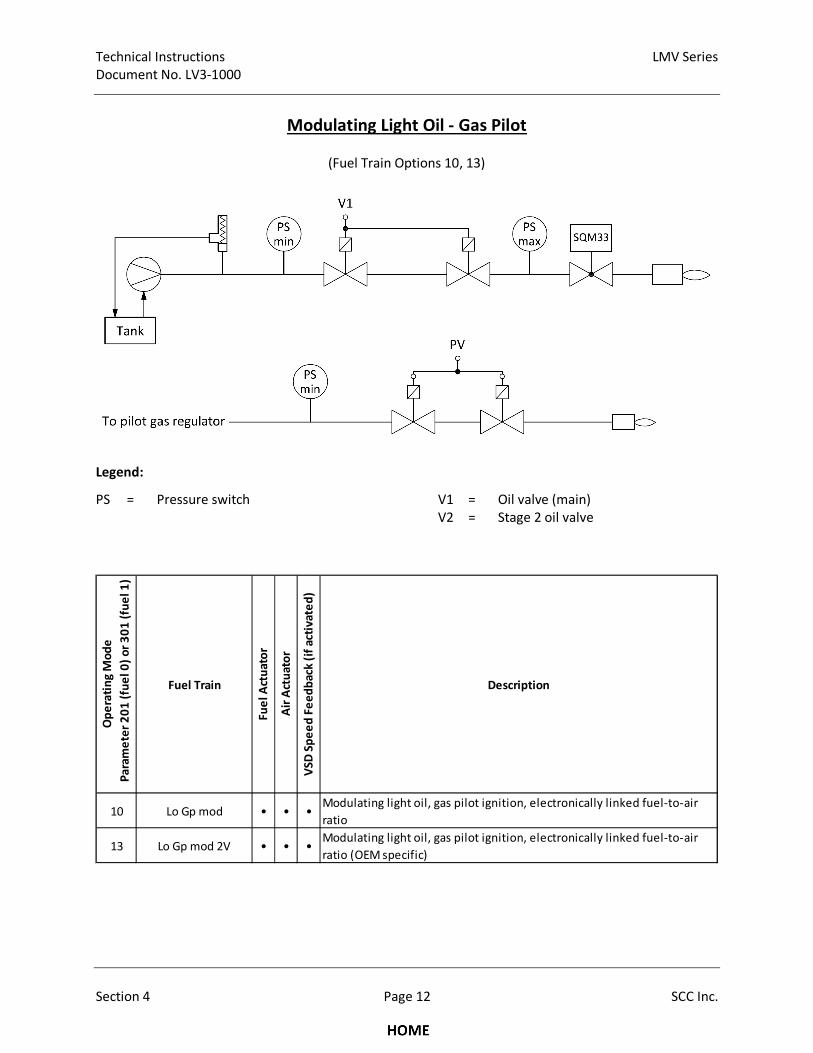
Technical Instructions LMV Series
Document No. LV3-1000
Section 4 Page 12 SCC Inc.
Modulating Light Oil - Gas Pilot
(Fuel Train Options 10, 13)
Legend:
PS = Pressure switch V1 = Oil valve (main)
V2 = Stage 2 oil valve
Op
era
tin
g M
od
e
Pa
ram
ete
r 2
01
(fu
el
0)
or
30
1 (
fue
l 1
)
Fuel Train
Fu
el
Act
ua
tor
Air
Act
ua
tor
VS
D S
pe
ed
Fe
ed
ba
ck (
if a
ctiv
ate
d)
Description
10 Lo Gp mod • • •Modulating light oil, gas pilot ignition, electronically linked fuel-to-air
ratio
13 Lo Gp mod 2V • • •Modulating light oil, gas pilot ignition, electronically linked fuel-to-air
ratio (OEM specific)
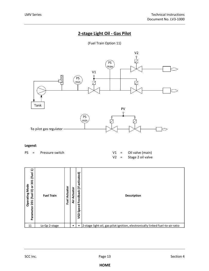
LMV Series Technical Instructions
Document No. LV3-1000
SCC Inc. Page 13 Section 4
2-stage Light Oil - Gas Pilot
(Fuel Train Option 11)
Legend:
PS = Pressure switch V1 = Oil valve (main)
V2 = Stage 2 oil valve
Op
era
tin
g M
od
e
Pa
ram
ete
r 2
01
(fu
el
0)
or
30
1 (
fue
l 1
)
Fuel Train
Fu
el
Act
ua
tor
Air
Act
ua
tor
VS
D S
pe
ed
Fe
ed
ba
ck (
if a
ctiv
ate
d)
Description
11 Lo Gp 2-stage • • 2-stage light oil, gas pilot ignition, electronically linked fuel-to-air ratio
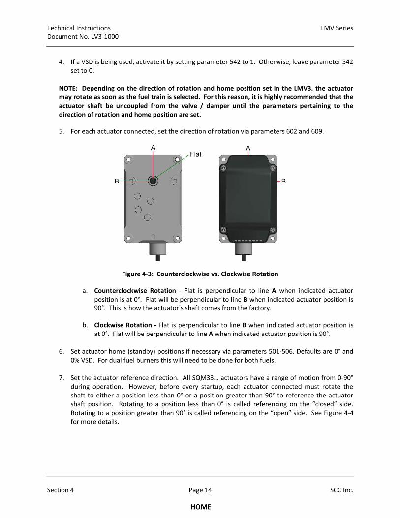
Technical Instructions LMV Series
Document No. LV3-1000
Section 4 Page 14 SCC Inc.
4. If a VSD is being used, activate it by setting parameter 542 to 1. Otherwise, leave parameter 542
set to 0.
NOTE: Depending on the direction of rotation and home position set in the LMV3, the actuator
may rotate as soon as the fuel train is selected. For this reason, it is highly recommended that the
actuator shaft be uncoupled from the valve / damper until the parameters pertaining to the
direction of rotation and home position are set.
5. For each actuator connected, set the direction of rotation via parameters 602 and 609.
Figure 4-3: Counterclockwise vs. Clockwise Rotation
a. Counterclockwise Rotation - Flat is perpendicular to line A when indicated actuator
position is at 0°. Flat will be perpendicular to line B when indicated actuator position is
90°. This is how the actuator's shaft comes from the factory.
b. Clockwise Rotation - Flat is perpendicular to line B when indicated actuator position is
at 0°. Flat will be perpendicular to line A when indicated actuator position is 90°.
6. Set actuator home (standby) positions if necessary via parameters 501-506. Defaults are 0° and
0% VSD. For dual fuel burners this will need to be done for both fuels.
7. Set the actuator reference direction. All SQM33… actuators have a range of motion from 0-90°
during operation. However, before every startup, each actuator connected must rotate the
shaft to either a position less than 0° or a position greater than 90° to reference the actuator
shaft position. Rotating to a position less than 0° is called referencing on the “closed” side.
Rotating to a position greater than 90° is called referencing on the “open” side. See Figure 4-4
for more details.
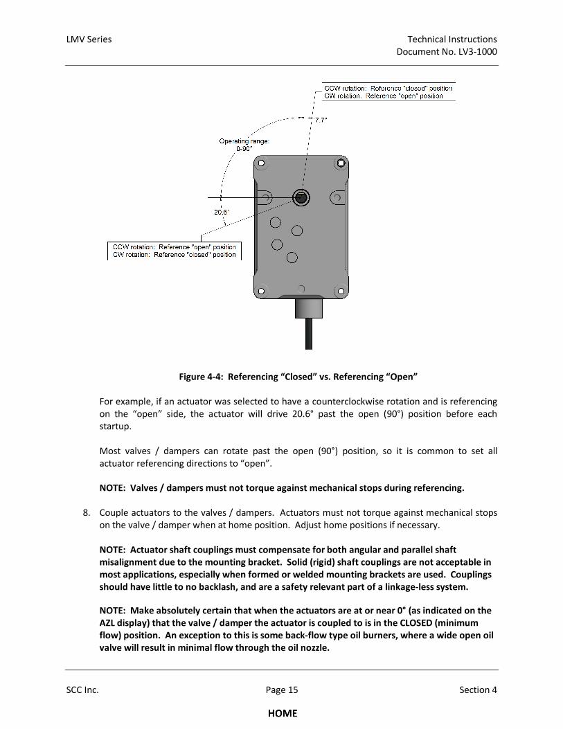
LMV Series Technical Instructions
Document No. LV3-1000
SCC Inc. Page 15 Section 4
Figure 4-4: Referencing “Closed” vs. Referencing “Open”
For example, if an actuator was selected to have a counterclockwise rotation and is referencing
on the “open” side, the actuator will drive 20.6° past the open (90°) position before each
startup.
Most valves / dampers can rotate past the open (90°) position, so it is common to set all
actuator referencing directions to “open”.
NOTE: Valves / dampers must not torque against mechanical stops during referencing.
8. Couple actuators to the valves / dampers. Actuators must not torque against mechanical stops
on the valve / damper when at home position. Adjust home positions if necessary.
NOTE: Actuator shaft couplings must compensate for both angular and parallel shaft
misalignment due to the mounting bracket. Solid (rigid) shaft couplings are not acceptable in
most applications, especially when formed or welded mounting brackets are used. Couplings
should have little to no backlash, and are a safety relevant part of a linkage-less system.
NOTE: Make absolutely certain that when the actuators are at or near 0° (as indicated on the
AZL display) that the valve / damper the actuator is coupled to is in the CLOSED (minimum
flow) position. An exception to this is some back-flow type oil burners, where a wide open oil
valve will result in minimal flow through the oil nozzle.
Technical Instructions LMV Series
Document No. LV3-1000
Section 4 Page 16 SCC Inc.
9. With the burner off, stroke each valve / damper through its intended range of motion using the
SQM33… actuator that is now coupled to the valve / damper. This can be achieved by changing
the home positions of each actuator via parameters 501-506.
Verify that no binding will occur through the intended range of motion. Also note valves /
dampers where the fully open position is less than 90°. Once the full range of motion of the
valve / damper has been tested, set the home positions back to their intended settings.
10. Set the pre-purge and post-purge positions for all connected actuators via parameters 501-506.
For dual fuel burners this will need to be done for both fuels.
11. If the burner has a Variable Speed Drive (VSD) on the blower, it must be standardized. If the
burner is equipped with a VFD, see Section 5 in this literature if the VFD parameters are not
already set, and for a more detailed standardization procedure. PWM blowers are typically pre-
programmed and do not require any additional programming. Once the VSD parameters are
set, standardize the VSD via parameter 641.
Once parameter 641 is set to 1, the air damper should open to its pre-purge position, and the
blower should ramp up, pause, and then ramp back down. If the value of parameter 641
changes back to 0, standardization was completed successfully. If the value changes to a
negative number, see error code 82 for the cause of the failure.
NOTE: Standardization will not occur if the safety loop is open. Make sure the safety loop is
closed before attempting standardization.
12. At this point, all other LMV3 parameters should be reviewed and set accordingly for the
individual burner requirements.
Section 3 of this literature explains every parameter in detail, and the most commonly used
parameters are shaded for easy reference.
LMV Series Technical Instructions
Document No. LV3-1000
SCC Inc. Page 17 Section 4
Transferring Parameter Sets Using the AZL Display
This procedure will detail how to transfer a parameter set from one burner to another burner. In this
example, the parameter set will originate from Burner #1 (B1) and will be copied to Burner #2 (B2).
Naturally, using a similar procedure, the parameter set from Burner #1 can be copied to Burners #3, #4,
#5, etc. The ACS410 PC software can also be used for this purpose (see Section 8).
Note: Passwords are transferred with the parameter sets.
1. Obtain the OEM or service level passwords for B1 and B2.
2. On B1, download all of the current parameters from the LMV3 to the AZL flash memory via
parameter 050. Select “Backup” and set the parameter to 1. This will begin the parameter
download. This process is complete when the value changes back to 0. If the value changes to
any number other than 0, a fault occurred during the parameter download.
3. Write down B1 burner ID. This can be found via parameter 113.
After this step, B1 LMV3 can be powered off. After B1 is powered off, remove the AZL.
4. If the burner ID on B2 is not the same as B1, change the burner ID on B2 to match B1 via
parameter 113. The OEM or service level password will be required to change the burner ID.
5. Power off B2 LMV3. After B2 LMV3 is powered off, remove the AZL from B2 and replace with
the AZL from B1. Power B2 LMV3 back on.
6. Now that the burner IDs match, the B1 parameter set can be downloaded into B2 via parameter
050. Select “Restore” and set the parameter to 1. This will upload all of the parameters from B1
AZL into the LMV3 on B2. This process is complete when the value changes back to 0. If the
value changes to any number other than 0, a fault occurred during the parameter upload.
7. After this is complete, B2 can be powered down. The AZL from B1 can be returned to B1 and the
AZL from B2 can be reconnected to B2. Power B2 LMV3 back on.
8. Change the burner ID on B2 to a unique value different than B1. Typically, the burner serial
number is used.
NOTE: An exact copy of all parameters is transferred when the above procedure is executed,
including light-off positions and Fuel-to-Air Ratio Control Curves. Typically, even "identical"
burners and boilers need unique light-off positions and Fuel-to-Air Ratio Control Curves. Since
this is typically the case, curves and ignition positions are typically deleted or modified after
the parameter set is downloaded into a new burner.
Technical Instructions LMV Series
Document No. LV3-1000
Section 4 Page 18 SCC Inc.
Suggested Initial Light-off for LMV3 Systems
1. The following procedure assumes the following:
a. Fuel train 3 (Gp2 mod) was selected for a gas pilot burner.
b. Pre-requisites for Basic LMV3 systems (from above) are met.
c. Procedure for Configuring (Parameterization of) an LMV3 has been done (from above).
d. This is a first-time commissioning of the LMV3 and the combustion control curve is blank
(no points are entered).
2. Close the manual main fuel (gas) valve that is downstream of the low gas pressure switch and
pilot take-off.
3. Ensure the burner switch is off. If the LMV3 is not yet powered, turn on the power to the LMV3.
4. At this point, all safety interlocks that can be checked should be checked in a safe manner. This
includes, but is not limited to: low water cut-offs, high temperature switches, high gas pressure
switch, low gas pressure switch, proof of closure (POC) switch, etc.
5. Later in the procedure when the burner is running, the rest of the safety interlocks must be
checked in a safe manner. This includes, but is not limited to: Air pressure switches, high steam
pressure limits, draft switches, etc.
6. Hold down the F and A buttons together to access the LMV3 parameters. If not already logged
in, log in using the OEM password. The default OEM password is “EntrY”. When parameter 400
is displayed, press Enter.
7. Parameter 201 will be displayed. Parameter 201 sets the fuel train type. This was set in an
earlier step. If no changes are necessary, press the + button.
8. Parameter 542 will be displayed. Parameter 542 activates or deactivates the use of a VSD. This
was set in an earlier step. If no changes are necessary, press the + button.
9. Parameter 641 will be displayed. Parameter 641 is used to standardize the VSD (if used). This
was performed in an earlier step. If no changes are necessary, press the + button.
10. P0 will be displayed. P0 is the ignition position of the actuators and VSD. Hold down the F
button and use the + and - buttons to set the ignition position for the fuel actuator. Hold down
the A button and use the + and - buttons to set the ignition position for the air actuator. Hold
down both the F and A buttons together and use the + and - buttons to set the ignition speed
for the VSD. Once the safe ignition positions have been entered, press the + button.
11. P9 will be displayed. P9 is the high fire position of the actuators and VSD. Enter the same values
that were used for ignition position P0. Once the safe high fire positions have been entered,
press the + button.
LMV Series Technical Instructions
Document No. LV3-1000
SCC Inc. Page 19 Section 4
12. The word “run” will be displayed. If the burner is ready to be turned on, press Enter.
13. The LMV3 will now be in Phase 12 and the burner is ready to be turned on. Turn on the burner
switch. The burner should drive to pre-purge (Phase 24) and then drive to ignition (Phase 36).
P0 will be displayed again. If no changes are desired for the ignition position, press the + button
to attempt to light the pilot.
14. The pilot should light and the LMV3 should move to pilot stabilization (Phase 44). If the pilot
does not light on a new installation, there could be air in the gas line. Bleed the air in a safe
manner if necessary and attempt to re-light the pilot.
15. P0 will be displayed again once the pilot is lit. Tune the pilot by adjusting the ignition position of
the air actuator and / or adjusting the pilot gas pressure regulator, if necessary. Pilot flame
should be stable and return a flame signal of 85% or greater. To view the flame signal, hold
down the Enter button.
16. Once a satisfactory pilot flame is established, press the + button. The burner should open the
main fuel (gas) valves and attempt to light the main flame. The LMV3 should show a flame
failure since the manual main fuel (gas) valve is closed.
17. If a flame failure does occur, turn off the burner switch and proceed to reset the LMV3. The text
“OFF UPr…” should be displayed. Open the manual main fuel (gas) valve. To start the burner
again, use the procedure from steps 6, 12, 13, 14, and 15 above to light the pilot off again. Once
the pilot flame is established again and P0 is displayed, press the + button and attempt to light
the main flame.
18. If the main flame lights, P0 will be displayed one last time. Adjust the ignition position of the gas
valve to achieve a safe main flame. At this time, a calibrated stack gas analyzer should be
inserted into the stack and used to evaluate combustion. If the main flame fails to light, the
ignition position of the firing rate control valve and / or the gas pressure regulator may need to
be adjusted to achieve a combustible mixture at the ignition position. After the combustion has
been verified to be safe with an analyzer, parameter 208 can be set to 4 to hold the boiler at
ignition position for a boil out or boiler warming if required.
Suggested Ratio Control Curve Commissioning
1. The procedure below assumes the following:
a. Pre-requisites for Basic LMV3 systems (from above) are met.
b. Procedure for Configuring (Parameterization of) an LMV3 has been done (from above).
c. This is a first-time commissioning of the LMV3 and the combustion control curve is blank
(no points entered).
d. The burner has been lit off, and is at ignition position.
e. A calibrated stack gas analyzer is sampling the stack gas and can read %O2 and ppm CO.
f. The boiler has been warmed up to operating temperature / pressure.
Technical Instructions LMV Series
Document No. LV3-1000
Section 4 Page 20 SCC Inc.
2. A free excel spreadsheet is available to assist in creating smooth fuel-to-air ratio curves and to
record commissioning data for reference. This spreadsheet, called the LMVx Curves
spreadsheet, can be found at www.scccombustion.com. The spreadsheet uses fuel flow to
accurately lay out the fuel-to-air ratio curves. If fuel flow is not available, burner head pressure
can be used as a last resort.
The next page shows how the LMVx Curves spreadsheet can be used to set up a steam boiler
with a fuel actuator, air actuator, and a VSD. This is an example to illustrate what a typical setup
might look like, and is not intended to be copied verbatim to an LMV3 in the field.
3. Press the + button to go to Point 1 (P1). Point 1 is automatically set to ignition position values.
NOTE: The text “P1” will be solid when the actuators / VSD are moving to the displayed
position. The text “P1” will begin flashing when the indicated positions are reached.
4. If the low fire point is not known (maximum burner turndown), adjust the Point 1 actuator / VSD
positions until maximum safe burner turndown is achieved. Once the desired low fire actuator /
VSD positions have been achieved, record the Point 1 actuator / VSD positions and burner
turndown in the LMVx Curves spreadsheet.
NOTE: While commissioning the Ratio Control Curves, it is the responsibility of the technician
to ensure that safe fuel-to-air ratios are being maintained. If an AZL23 + or - button is held
down when adjusting an actuator position, the position will be changed at a progressively
faster rate.
5. Press the + button eight times until P9 (high fire) is displayed. Now increase the effective firing
rate of the burner by increasing the actuator / VSD positions in a way that maintains a safe fuel-
to-air ratio. This is typically accomplished by increasing air, fuel, and VSD positions in a stepwise
rotation. Keep increasing the firing rate in this manner until high fire positions of the actuators /
VSD are reached.
NOTE: Typically, the gas pressure regulator immediately upstream of the firing rate control
valve will need to be adjusted on a new installation. Adjust the regulator such that the firing
rate control valve is between 60-80° open at high fire.
6. Once high fire actuator / VSD positions and gas pressure regulator(s) are set, record the Point 9
actuator / VSD positions, burner head pressure at high fire, and burner output at high fire in the
LMVx Curves spreadsheet.
Now that P1 (low fire) and P9 (high fire) have been set, and all of the appropriate information
has been entered into the LMVx Curves spreadsheet, the fuel flow (or burner head pressure) at
the remaining points on the fuel-to-air ratio curves are displayed in the spreadsheet.
NOTE: Exactly nine curve points (P1-P9), plus ignition position P0, are required to be entered.
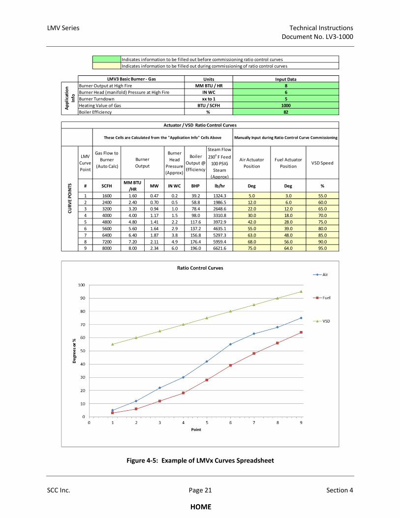
LMV Series Technical Instructions
Document No. LV3-1000
SCC Inc. Page 21 Section 4
Figure 4-5: Example of LMVx Curves Spreadsheet
Burner Head (manifold) Pressure at High Fire
Burner Turndown
Heating Value of Gas
Boiler Efficiency
LMV
Curve
Point
Gas Flow to
Burner
(Auto Calc)
Burner
Head
Pressure
(Approx)
Boiler
Output @
Efficiency
Steam Flow
230o F Feed
100 PSIG
Steam
(Approx)
Air Actuator
Position
Fuel Actuator
PositionVSD Speed
# SCFHMM BTU
/HRMW IN WC BHP lb/hr Deg Deg %
1 1600 1.60 0.47 0.2 39.2 1324.3 5.0 3.0 55.0
2 2400 2.40 0.70 0.5 58.8 1986.5 12.0 6.0 60.0
3 3200 3.20 0.94 1.0 78.4 2648.6 22.0 12.0 65.0
4 4000 4.00 1.17 1.5 98.0 3310.8 30.0 18.0 70.0
5 4800 4.80 1.41 2.2 117.6 3972.9 42.0 28.0 75.0
6 5600 5.60 1.64 2.9 137.2 4635.1 55.0 39.0 80.0
7 6400 6.40 1.87 3.8 156.8 5297.3 63.0 48.0 85.0
8 7200 7.20 2.11 4.9 176.4 5959.4 68.0 56.0 90.0
9 8000 8.00 2.34 6.0 196.0 6621.6 75.0 64.0 95.0
CU
RV
E P
OIN
TS
Burner
Output
Manually Input during Ratio Control Curve Commissioning
Actuator / VSD Ratio Control Curves
These Cells are Calculated from the "Application Info" Cells Above
% 82
BTU / SCFH 1000
Ap
pli
cati
on
Info
MM BTU / HR 8
xx to 1 5
Burner Output at High Fire
IN WC 6
Units Input Data
Indicates information to be filled out before commissioning ratio control curves
Indicates information to be filled out during commissioning of ratio control curves
LMV3 Basic Burner - Gas
Technical Instructions LMV Series
Document No. LV3-1000
Section 4 Page 22 SCC Inc.
7. Still at P9 (high fire), hold the - button down until “CALC” is displayed.
NOTE: The CALC feature draws a linear curve between the point just set and either P1 (low
fire) or P9 (high fire). Holding the + button after setting any curve point will linearize the
curve from that point up to P9 (high fire). Holding the - button after setting any curve point
will linearize the curve from that point down to P1 (low fire).
At this point, a linear curve is entered between Point 1 (low fire) and Point 9 (high fire). Moving
now from Point 8 down to Point 1, continue to set each point at the calculated fuel flow (or
burner head pressure). After each point has been set to achieve safe, efficient combustion and
emissions compliance, hold the - key to perform the CALC function again and move to the next
point. After Point 1 has been set, press the Escape button.
8. Parameter 546 will be displayed. Parameter 546 sets the maximum fire rate of the burner.
Once this has been set, press the + button.
9. Parameter 545 will be displayed. Parameter 545 sets the minimum fire rate of the burner. Once
this has been set, press the Escape button.
NOTE: Parameter 545 can only be set as low as 20%. This does not mean that the turndown
of the burner is limited to 5:1. The LMV3 always denotes low fire as 20% load, even though
the actuator / VSD positions set at Point 1 can achieve a much lower fire rate.
10. Parameter 400 appears. Press Escape. If the curve was set up correctly, the display should now
show “oP” followed by the fire rate of the burner.
11. The following is a summary of what should be achieved for each point on the Ratio Control
Curve:
a. Safe, efficient combustion as verified by a calibrated stack gas analyzer
b. Emissions compliance
c. Smooth Ratio Control Curves (no sharp peaks and valleys)
d. VSD speed should increase with load in a linear fashion (if equipped)
LMV Series Technical Instructions
Document No. LV3-1000
SCC Inc. Page 23 Section 4
Additional Tips for Commissioning
• Using a fuel flow meter (temporary or permanent) for commissioning is always a good idea. If
the fuel input (heat output) increases linearly with firing rate, the PID loop in any load control
will be much more effective. A temporary, insertion type flow meter is available from SCC Inc.
for this purpose.
• If burner head pressure must be used as a last resort to estimate firing rate, bear in mind that
head pressure does not increase with gas flow in a linear manner. There is a square root
relationship between the differential pressure across the burner head and the gas flow. This
relationship is very similar to how the pressure varies across a fixed orifice with an increase or
decrease in flow. Also, furnace pressure must be accounted for by hooking up both sides of the
manometer, one side to the burner head pressure and one side to the furnace pressure.
• Carbon monoxide (CO) is produced when combustion is incomplete, typically due to the flame
being too rich or too lean. CO is potentially explosive when mixed with air in the right
proportions. For CO to be explosive in air, it must reach a concentration of at least 12.5%
(125,000 ppm) with an ignition source present.
• If a burner is commissioned properly, actuator curves should increase smoothly with increasing
load (firing rate). Curves should always be smooth, with no sharp corners.
• The best and fastest method to commission a burner with an LMV3 is to set up a small table
where the technician can have his laptop, AZL, fuel flow meter, and external flue gas analyzer all
within arm's reach. This allows the curve points to be input rapidly and accurately. If the
information is entered in the laptop point by point, a very nice startup report will also be
generated.
• The ACS410 software is not as fast as using the AZL to commission the LMV3. Since this is the
case, the ACS410 is typically not used to commission the LMV3. However, the ACS410 is very
valuable when used to download a startup report (all parameter settings, fault and lockout
history, in English) and also when used to download parameter backups (the machine-language
parameter set from the LMV3). It is recommended to download both of these files after
commissioning, so that there is a backup record of all parameter and curve settings.
• Pressing the Enter button and any other button on the AZL at the same time will cause the LMV3
to immediately close the fuel valves and lockout.

Technical Instructions LMV Series
Document No. LV3-1000
Section 4 Page 24 SCC Inc.
Intentionally Left Blank
Section 1 Overview
Section 2 Wiring
Section 3 Parameters
Section 4 Commissioning
Section 5 VSD
Section 6 Troubleshooting
Section 7 Modbus
Section 8 ACS410
Appendix A Application Guide

Section 1 Overview
Section 2 Wiring
Section 3 Parameters
Section 4 Commissioning
Section 5 VSD
Section 6 Troubleshooting
Section 7 Modbus
Section 8 ACS410
Appendix A Application Guide
LMV Series Technical Instructions
Document No. LV3-1000
SCC Inc. Page 1 Section 5
Section 5: Variable Speed Drive Control
Table of Contents
Introduction ................................................................................................................................ 2
VFD and AC Induction Motor Fundamentals ................................................................................ 2
Line Reactors............................................................................................................................... 3
Output Wiring / Load Reactors .................................................................................................... 4
Shaft Current............................................................................................................................... 5
Braking Resistors ......................................................................................................................... 5
Types of VFDs: Vector and Volt/Hz ............................................................................................. 7
Configuring VFDs for use with the LMV3 ..................................................................................... 7
Brushless DC Blowers (PWM Blowers) ......................................................................................... 9
Centrifugal Blower Fundamentals ............................................................................................. 10
Standardized Speed - Standardizing the LMV3 .......................................................................... 11
Blower Speed Monitoring ......................................................................................................... 16
Blower Speed Response during Operation ................................................................................ 18
Suggested Setup Procedure for the VSD Control - Parallel Positioning Application .................... 20
Suggested Setup Procedure for the VSD Speed Shift ................................................................. 23
Additional Tips for Burners with VSD Speed Shift ...................................................................... 27
Additional Tips for Burners with VSD Control ............................................................................ 28
Technical Instructions LMV Series
Document No. LV3-1000
Section 5 Page 2 SCC Inc.
Introduction
The LMV3 features an integrated, closed-loop Variable Speed Drive (VSD) control that is typically used to
ramp the speed of the combustion air blower with firing rate. This is accomplished by transmitting a 0-
10 VDC or a PWM (pulse-width modulation) signal from the LMV3 to the VSD, and then reading back the
speed of the blower motor. The blower motor speed feedback can be accomplished two different ways.
For three phase AC motors, a motor shaft mounted, safety-rated asymmetrical encoder wheel (speed
wheel) and speed sensor is typically used. For DC brushless motors (PWM blowers), the speed signal is
taken from Hall Effect sensors that commutate the brushless DC blower motor. On three phase motors
where the direction of rotation can be easily changed, the LMV3 also monitors the direction of rotation
with the asymmetrical encoder wheel, ensuring safe VSD operation.
Blower speed and direction of rotation have a large impact on the airflow delivered to the burner, and
thus the fuel-air ratio. The most common type of VSD, a Variable Frequency Drive (VFD), is typically not
safety-rated and will typically not fail in a safe manner (a VFD failure will typically cause the combustion
air blower to slow down or stop, causing the burner to go rich). The combustion air pressure switch
offers only a small amount of protection in a VFD application, since the switch must be set to allow low
fire operation when the blower is spinning slowly and the blower output pressure is low. Blower speed
feedback ensures that a blower failure will be quickly detected and the burner will shut down safely.
VFD and AC Induction Motor Fundamentals
VFDs are typically connected to a three-phase alternating current (AC) induction motor that is used to
power the combustion air blower. Modern VFDs operate by taking single or three-phase AC and
rectifying this power to high voltage direct current (DC) for the DC bus. The AC power is typically
rectified to DC with banks of diodes. The DC bus feeds a bank of Insulated Gate Bipolar Transistors
(IGBTs), and a microprocessor is used to fire the IGBTs in a way that the voltage and frequency of the
modified sine waves can be controlled. This is done for each of the three phases on the VFD output.
The microprocessor varies the voltage and frequency of the modified sine waves in response to a signal;
in this case, the 0-10 VDC input.
By design, a three-phase AC induction motor will attempt to approximately synchronize its speed with
the frequency of three-phase power that it is being fed. Thus, if the frequency can be adjusted, so can
the speed of the motor. As their name suggests, three-phase induction motors generate magnetic fields
in the rotor of the motor by using induction rather than by using slip rings or brushes. The advantage of
this type of construction is very low maintenance, and a small disadvantage is a phenomenon called slip.
Slip is defined as the difference between the theoretical speed at a given AC frequency and the actual
speed at a given AC frequency. Slip increases as the load on the motor (torque output) increases.
Three-phase AC motors that do not have slip are referred to as synchronous motors, since these motors
exactly synchronize their speed to the frequency of the incoming AC power. This type of motor is not
typically used on blowers, but is mentioned as a comparison to the AC induction motor. A truly
synchronous 2-pole motor will spin at exactly 3600 RPM if it is fed exactly 60 Hz. A truly synchronous 4-
pole motor will spin at exactly 1800 RPM if it is fed exactly 60 Hz. In contrast, a 2-pole, three-phase AC
induction motor fed 60 Hz will spin less than 3600 RPM, and how much less is determined by how
heavily the motor is loaded and how much slip that loading causes.
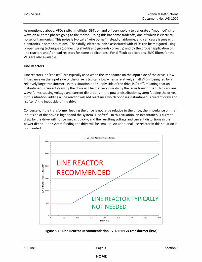
LMV Series Technical Instructions
Document No. LV3-1000
SCC Inc. Page 3 Section 5
As mentioned above, VFDs switch multiple IGBTs on and off very rapidly to generate a "modified" sine
wave on all three phases going to the motor. Doing this has some tradeoffs, one of which is electrical
noise, or harmonics. This noise is typically "wire borne" instead of airborne, and can cause issues with
electronics in some situations. Thankfully, electrical noise associated with VFDs can be mitigated using
proper wiring techniques (connecting shields and grounds correctly) and by the proper application of
line reactors and / or load reactors for some applications. For difficult applications, EMC filters for the
VFD are also available.
Line Reactors
Line reactors, or "chokes", are typically used when the impedance on the input side of the drive is low.
Impedance on the input side of the drive is typically low when a relatively small VFD is being fed by a
relatively large transformer. In this situation, the supply side of the drive is "stiff", meaning that an
instantaneous current draw by the drive will be met very quickly by the large transformer (think square
wave form), causing voltage and current distortions in the power distribution system feeding the drive.
In this situation, adding a line reactor will add reactance which opposes instantaneous current draw and
"softens" the input side of the drive.
Conversely, if the transformer feeding the drive is not large relative to the drive, the impedance on the
input side of the drive is higher and the system is "softer". In this situation, an instantaneous current
draw by the drive will not be met as quickly, and the resulting voltage and current distortions in the
power distribution system feeding the drive will be smaller. An additional line reactor in this situation is
not needed.
Figure 5-1: Line Reactor Recommendation - VFD (HP) vs Transformer (kVA)
Technical Instructions LMV Series
Document No. LV3-1000
Section 5 Page 4 SCC Inc.
In general, a line reactor is recommended if the supply capacity (kVA) of the transformer feeding the
drive is greater than or equal to 10 times the capacity (kVA) of the drive for transformers 600 kVA and
larger.
Figure 5-1 notes:
1. Drive power is shown in HP rather than kVA. This conversion can be done assuming a power factor
of unity (1) and negligible losses due to efficiency.
2. Transformers less than 600 kVA have high enough impedance (are “soft” enough) so that line
reactors are typically not necessary.
Example 1: A 25 HP drive is being fed by an 800 kVA transformer. Is a line reactor required?
Assumptions:
The power factor is unity (power factor = 1)
Losses due to efficiency and wiring are negligible
1. Convert horsepower to kilowatts: 25 HP x 0.745 HP/kW = 18.63 kW
2. Convert kilowatts to kVA: kW = kVA * Pf (Pf is power factor, which is assumed to be 1 in this
example)
Thus, a 25 HP drive is 18.63 kVA.
3. Calculate the kVA ratio: 800 kVA / 18.63 kVA = 42.94
Since a ratio of 42.94 is greater than 10, and the transformer is larger than 600 kVA, a line
reactor will be necessary for this application. The same conclusion can also be arrived at by
using Figure 5-1.
Example 2: A 10 HP drive is fed by a 400 kVA transformer. Is a line reactor required?
Using the same assumptions and calculation as example 1, the kVA ratio is 53.7, but the transformer is
smaller than 600 kVA, so a line reactor is not necessary. The same conclusion can also be arrived at by
using Figure 5-1.
Output Wiring / Load Reactors
When the VFD / motor are running, high levels of electrical noise are produced on the wiring between
the VFD and the motor. This is due to the fact that modified sine waves produced by the drive IGBTs are
basically high frequency / high voltage DC pulses. These output wires must be enclosed in some type of
shielding (metallic conduit or metal-shielded cable) to mitigate radiated electrical noise.
Wire length between the VFD and the motor should be kept to less than 150 feet if possible due to the
reflected wave / standing wave phenomenon and voltage overshoot phenomenon. Both of these
phenomena are rather complex, and are a function of the wire length from the VFD to the motor. The
reflected wave / standing wave phenomenon and voltage overshoot phenomenon can damage non-
inverter duty motor windings over time due to the high peak voltages that these phenomena can
produce.
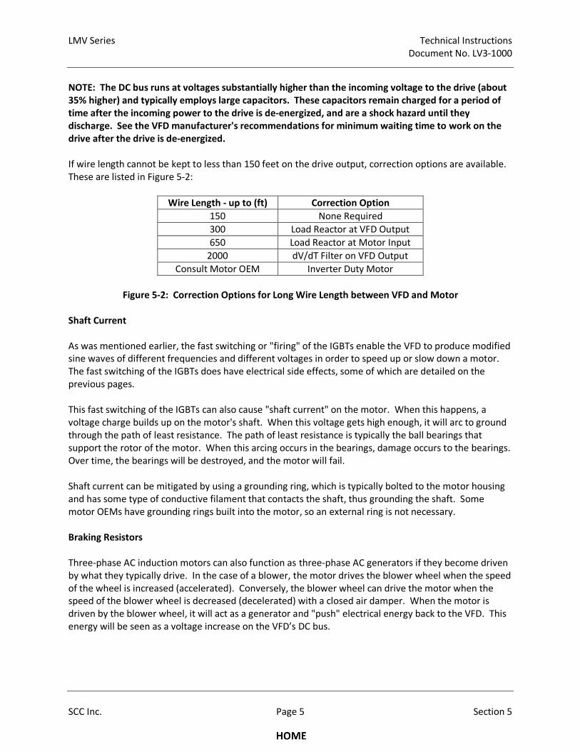
LMV Series Technical Instructions
Document No. LV3-1000
SCC Inc. Page 5 Section 5
NOTE: The DC bus runs at voltages substantially higher than the incoming voltage to the drive (about
35% higher) and typically employs large capacitors. These capacitors remain charged for a period of
time after the incoming power to the drive is de-energized, and are a shock hazard until they
discharge. See the VFD manufacturer's recommendations for minimum waiting time to work on the
drive after the drive is de-energized.
If wire length cannot be kept to less than 150 feet on the drive output, correction options are available.
These are listed in Figure 5-2:
Wire Length - up to (ft) Correction Option
150 None Required
300 Load Reactor at VFD Output
650 Load Reactor at Motor Input
2000 dV/dT Filter on VFD Output
Consult Motor OEM Inverter Duty Motor
Figure 5-2: Correction Options for Long Wire Length between VFD and Motor
Shaft Current
As was mentioned earlier, the fast switching or "firing" of the IGBTs enable the VFD to produce modified
sine waves of different frequencies and different voltages in order to speed up or slow down a motor.
The fast switching of the IGBTs does have electrical side effects, some of which are detailed on the
previous pages.
This fast switching of the IGBTs can also cause "shaft current" on the motor. When this happens, a
voltage charge builds up on the motor's shaft. When this voltage gets high enough, it will arc to ground
through the path of least resistance. The path of least resistance is typically the ball bearings that
support the rotor of the motor. When this arcing occurs in the bearings, damage occurs to the bearings.
Over time, the bearings will be destroyed, and the motor will fail.
Shaft current can be mitigated by using a grounding ring, which is typically bolted to the motor housing
and has some type of conductive filament that contacts the shaft, thus grounding the shaft. Some
motor OEMs have grounding rings built into the motor, so an external ring is not necessary.
Braking Resistors
Three-phase AC induction motors can also function as three-phase AC generators if they become driven
by what they typically drive. In the case of a blower, the motor drives the blower wheel when the speed
of the wheel is increased (accelerated). Conversely, the blower wheel can drive the motor when the
speed of the blower wheel is decreased (decelerated) with a closed air damper. When the motor is
driven by the blower wheel, it will act as a generator and "push" electrical energy back to the VFD. This
energy will be seen as a voltage increase on the VFD’s DC bus.
Technical Instructions LMV Series
Document No. LV3-1000
Section 5 Page 6 SCC Inc.
The DC bus can absorb a small amount of energy in the DC bus capacitors. However, if the motor
generates more than what these capacitors can absorb, the DC bus voltage will rise to critical levels and
one of two actions will be taken by the VFD. Depending on the parameter settings of the VFD, the VFD
will either stop decelerating (stall prevention) or the VFD will alarm and shut down. Either one of the
actions is not a desirable result on a combustion air application.
To avoid DC bus overvoltage issues, a braking resistor can be added to the VFD so that the excess
electrical energy generated by decelerating the blower wheel can be turned to heat. This process
happens seamlessly so that the VFD can decelerate the blower smoothly.
Due to a number of variables, it is difficult to determine if a braking resistor will be needed on a
particular application unless that application has been tested. The only disadvantage of having a braking
resistor and not needing it is cost and possibly the space for the resistor. Burners having the following
characteristics will typically need a braking resistor:
1. A heavy, high inertia blower wheel - Kinetic energy is stored in a spinning wheel. The heavier the
blower wheel, the greater the stored energy. When this wheel is slowed down, the kinetic energy
must go somewhere, and it is usually "pushed" back to the VFD as electrical energy.
2. Fast ramp times - The faster the ramp times, the faster the blower wheel must be accelerated and
decelerated. Just like a car, more energy is required to accelerate quickly (bigger engine) and more
energy is required to be dissipated when decelerating quickly (bigger brakes). Decelerating a given
blower wheel more quickly will push more electrical energy back to the VFD.
3. Mostly closed air damper - A motor spinning at 3600 RPM draws fewer amps with a closed or nearly
closed air damper as compared to a wide open air damper. Thus, the horsepower used by the
motor and the drag (braking) on the blower wheel will be much less with a closed or nearly closed
air damper. Decelerating a given blower wheel with reduced drag will also push more electrical
energy back to the VFD.
As one might expect, the above points compound one another. Decelerating a heavy blower wheel
with a fast ramp time and a mostly closed air damper will push a large amount of electrical energy back
to the VFD and will likely cause DC bus overvoltage issues if a braking resistor is not installed.
In contrast, a light blower wheel (sheet metal instead of cast iron), a slower ramp time (90 seconds
instead of 30 seconds), and slowing the blower down on a more open air damper are characteristics that
will greatly reduce the amount of electrical energy pushed back to the VFD and should allow the braking
resistor to be omitted in most cases.
On some models of VFDs, braking resistors can be added after the VFD is installed if necessary. This is a
point to consider when installing VFDs for combustion air applications.
LMV Series Technical Instructions
Document No. LV3-1000
SCC Inc. Page 7 Section 5
Types of VFDs: Vector and Volt/Hz
Although there are over a hundred different manufacturers of VFDs, two main types of VFDs are
produced by these manufacturers for use on blower motors. These two types are Vector and Volt/Hz.
Vector VFDs can usually be run in either Vector mode or Volt/Hz mode. Vector VFDs are also typically
slightly more expensive than Volt/Hz VFDs for a given size.
The advantage of Vector VFDs is that they provide more accurate torque control of the motor. This
accurate torque control enables much more accurate speed control of the motor, especially at lower
motor speeds. More accurate speed control of the motor enables more accurate, repeatable control of
the airflow.
As mentioned earlier, the LMV3 employs a safety-related speed feedback on the blower shaft, thus
continuously checking and adjusting (if necessary) the signal to the VFD to achieve the desired blower
speed within a certain band. The LMV3 can lockout and shut down the burner if blower speed
deviations are large and persist for too long. Due to their increased accuracy, Vector VFDs provide
trouble-free operation on almost all LMV3 VFD blower applications. Volt/Hz VFDs can work
satisfactorily in some applications, but are not preferred due to their decreased accuracy.
Vector VFDs are typically run in Open Loop Vector (OLV) mode. In this mode, the VFD uses a
mathematical model of the motor combined with extremely accurate, fast scanning of the current and
other data taken from the rotating motor. In reality, Open Loop Vector mode does have feedback, but
the Vector VFD itself does not require a separate encoder to achieve this.
Since Vector VFDs use a mathematic model of the motor, and the design of motors differs somewhat
between motor OEMs, a static or dynamic auto-tune is sometimes required so that the Vector VFD
"learns" key aspects of the motor it is connected to. A static auto-tune (motor is not spun) does not
require that the load (blower wheel) be de-coupled from the motor. A dynamic auto-tune (motor is
spun) typically requires that the load (blower wheel) be de-coupled from the motor, which is not
possible or practical in many situations. A dynamic auto-tune typically generates the best "learning" of
the motor properties. A static auto-tune is typically all that is necessary if speed control issues are
encountered on a vector VFD.
Configuring VFDs for use with the LMV3
Modern VFDs typically have hundreds of parameters that can be set to tailor the VFD to a specific
application. As mentioned earlier, there are also at least a hundred different manufacturers of VFDs,
each of which have their own unique parameter list. Due to these two factors, SCC offers pre-
programmed VFDs that can be purchased with the VFD parameters set up for use with an LMV3.
If a VFD for use with an LMV3 is purchased and programmed independently, the following points will
serve as a general guideline for programming the VFD for the LMV3 application. Note that these
guidelines are necessarily general due to the variety of VFDs offered in the marketplace.
1. If a Vector VFD is used (recommended), set the "Control Method" to Open Loop Vector mode or
equivalent.
Technical Instructions LMV Series
Document No. LV3-1000
Section 5 Page 8 SCC Inc.
2. The stopping method (after the run / stop contact is opened) should be set to "Coast to Stop" to let
the motor coast to a stop after post-purge.
3. Reverse operation (the ability to reverse the motor with an input) should be disabled.
4. Configure the VFD to accept an external run / stop signal via a dry contact on the relay wired to the
LMV3 blower motor starter output.
5. The VFD should be able to do a "flying start" so that the VFD will not try to stop a free-wheeling
blower wheel before starting the wheel spinning again. Blower wheels frequently free-wheel due to
draft and other factors.
6. Ramp times - the VFD should be set to slightly faster ramp times compared to the LMV3 ramp times
(LMV3 parameters 522 Ramp Up VSD, 523 Ramp Down VSD and 544 ModulationRamp). For
example, if the LMV3 VSD ramp up time is set to 40 seconds, the ramp up time in the VFD should be
set no longer than 35 seconds. The same is true with the ramp down time. A 5 second differential
will work well in most situations.
Note: If short ramp times are necessary with large blowers (heavy blower wheels), a braking
resistor may be necessary. See the braking resistor explanation on the previous pages.
7. Ramps must be linear with the 0-10 VDC signal. S-shaped ramps and PID / filtering on the 0-10 VDC
signal will cause speed faults on the LMV3.
8. The VFD analog input signal should be configured for a 0-10 VDC signal and it should be spanned so
that 0 VDC = 0Hz and 10 VDC = 62 Hz (for blowers designed for 60 Hz power). The additional 2 Hz is
to make sure that full blower speed is achievable even with a 9.5 VDC standardization (see
standardization section below).
9. The motor nameplate data must be entered for the motor that the VFD is connected to.
10. Some VFDs have a feature that will stop ramping the drive if a critical limit in the drive is
approached. On some VFDs, this feature is referred to as "stall prevention". Two common limits are
the maximum amperage drawn and the DC bus voltage. Stall prevention, while protecting the drive,
can cause speed faults with the LMV3 due to the drive ceasing to ramp in concert with the LMV3. If
a braking resistor is used, stall prevention can typically be deactivated.
11. For Vector VFDs, perform at least a static auto-tune so that the VFD "learns" the characteristics of
the motor it is connected to. A static auto-tune does not require that the load (blower wheel) be
disconnected since the load is not spun. Some dynamic auto-tunes require that the load (blower
wheel) is disconnected.
12. If a braking resistor is being used, the braking resistor will typically have a high temperature switch.
The drive should be programmed and wired so that a braking resistor over temperature will cause
the drive to shut down.
LMV Series Technical Instructions
Document No. LV3-1000
SCC Inc. Page 9 Section 5
Brushless DC Blowers (PWM Blowers)
Another common type of variable speed blower used with the LMV3 is the brushless DC blower,
commonly referred to as a PWM blower. These blowers typically have the variable speed drive and DC
brushless motor integrated into one blower mounted unit. These blowers are typically fed single phase
or three phase AC voltage directly, and use some type of AC to DC rectification to produce the DC
voltage pulses necessary to drive the blower motor.
Unlike a brushed DC motor, field windings in the brushless motor are triggered (commutated) via non-
contact Hall Effect sensors. In addition to commutating the motor, these Hall Effect sensors also provide
a pulse output (typically 2 or 3 pulses per revolution) that the LMV3 can use for blower speed feedback.
For this reason, an external speed wheel with external speed sensor is not typically required for PWM
blowers. Wiring of the speed feedback signal is covered in Section 2 - Wiring.
Brushless DC motors usually do not have the same speed limitations as most three phase blower motors
do. While most three phase blower motors are limited to about 3800 RPM, some DC brushless motors
used in blower applications will spin in excess of 10,000 RPM. This high-speed capability is attractive in
a blower application since more air flow at higher pressures can be generated with a smaller blower.
The LMV3 can read blower speeds up to 14,000 RPM via the Hall Effect sensors in the blower, and this is
not a limitation in most applications.
Accurate speed control of a brushless DC motor can be more challenging as compared to a VFD and a
three phase AC motor. The primary reasons behind this are the electromechanical characteristics of the
motors themselves. As previously mentioned, the speed of a three phase AC motor will follow the
frequency of sine waves (AC power) that is being fed with a small amount of variance due to torque
induced slip. An increased torque (power) demand will cause a small amount of additional slip and will
cause greater amperage draw. Variances in voltage, unless these are extreme, will not cause the motor
to change speed. Thus frequency is the primary variable; voltage and torque are secondary variables. In
brushless DC motors, the motor windings are being fed DC pulses of variable duration (hence these
blowers being called pulse-width modulation - PWM). The width of these pulses determines the
blower’s speed for a given torque output and for a given blower input voltage. All three of these
variables – pulse width, torque output, and input voltage have a substantial impact on the blower’s
speed and can be regarded as primary variables.
Some PWM blowers have internal speed controls that compensate for torque output and input voltage
variances. This is done by taking a commanded speed set point (dictated by the LMV3) and adjusting
the width of the pulse to achieve the commanded speed. PWM blowers having fast updating, properly
tuned internal speed controls typically work well with the LMV3.
The ramp rates of a PWM blower carry many of the same considerations as a VFD with a three phase
motor (see above). Increasing the blower speed (ramping up) is typically not an issue; however, ramp
times may need to be increased when decreasing the blower speed (ramping down), especially if the
blower wheel is heavy and / or the air damper is mostly closed.
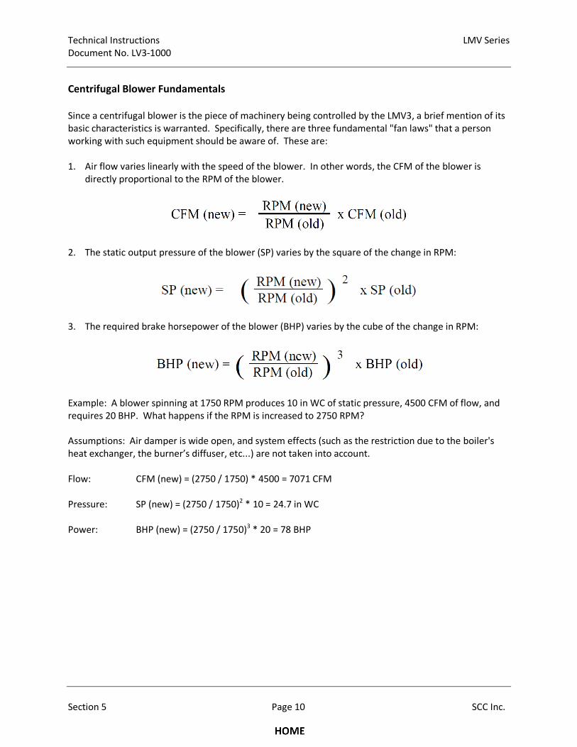
Technical Instructions LMV Series
Document No. LV3-1000
Section 5 Page 10 SCC Inc.
Centrifugal Blower Fundamentals
Since a centrifugal blower is the piece of machinery being controlled by the LMV3, a brief mention of its
basic characteristics is warranted. Specifically, there are three fundamental "fan laws" that a person
working with such equipment should be aware of. These are:
1. Air flow varies linearly with the speed of the blower. In other words, the CFM of the blower is
directly proportional to the RPM of the blower.
2. The static output pressure of the blower (SP) varies by the square of the change in RPM:
3. The required brake horsepower of the blower (BHP) varies by the cube of the change in RPM:
Example: A blower spinning at 1750 RPM produces 10 in WC of static pressure, 4500 CFM of flow, and
requires 20 BHP. What happens if the RPM is increased to 2750 RPM?
Assumptions: Air damper is wide open, and system effects (such as the restriction due to the boiler's
heat exchanger, the burner’s diffuser, etc...) are not taken into account.
Flow: CFM (new) = (2750 / 1750) * 4500 = 7071 CFM
Pressure: SP (new) = (2750 / 1750)2 * 10 = 24.7 in WC
Power: BHP (new) = (2750 / 1750)3 * 20 = 78 BHP
LMV Series Technical Instructions
Document No. LV3-1000
SCC Inc. Page 11 Section 5
Standardized Speed - Standardizing the LMV3
After the VSD blower is installed, wired and programmed correctly (see Section 2 for wiring), the LMV3
must be standardized.
The purpose of the standardization (calibration) procedure is to establish a relationship between the
speed signal sent to the VSD (0-10 VDC or PWM) and the actual speed (RPM) of the blower wheel. This
is done by correlating the speed signal to the actual RPM at two points: Near maximum speed and also
when the blower is stopped.
The near maximum speed is read by sending either a 95% or 98% speed signal to the VSD, and then
recording what speed was achieved. On the minimum speed side, 0% speed signal is assumed to be 0
RPM. The electronics in the LMV3 then “draw a line” between these two points (linear interpolation) to
establish the expected speed response of the blower to a given speed signal. See Figure 5-4.
The standardization procedure is automated, and is activated by setting parameter 641 to a value of 1.
When this is done, the following should occur:
1. The air damper is opened to pre-purge position.
2. The blower output (X3-05.1) is energized, closing a relay and enabling the VFD (if equipped).
3. A 95% or 98% speed signal is applied to the VSD. This can be a 0-10 VDC or a PWM signal. If
parameter 661 is set to 0, then a 95% signal will be used. If parameter 661 is set to 1, a 98% signal
will be used.
4. The blower ramps up to speed. After the speed has stabilized, the actual RPM is recorded by the
LMV3 and is stored under parameter 642.
5. The speed signal is returned to 0%, and the blower is allowed to ramp down.
6. The blower output (X3-05.1) is de-energized.
7. The air damper returns to its home position.
8. If a value of 0 appears on the AZL after standardization, then the procedure was completed without
error. If a value appears other than 0, see Error Code 82 in Section 6 of this manual.
NOTE: The LMV3 will not standardize if the safety loop is open, or if the burner switch is on. Ensure
that the safety loop is closed and the burner switch is off before attempting to standardize.
A typical standardization process for a 2-pole (~3600 RPM) three phase blower with VFD is shown
graphically in Figure 5-3. If a standardization was performed on a brushless DC blower (PWM blower)
the procedure would be similar but the peak blower speed would be substantially higher (typically 5,500
RPM to 14,000 RPM) and the speed signal used for standardization would be 98% due to parameter 661
being set to a value of 1 for a PWM blower.
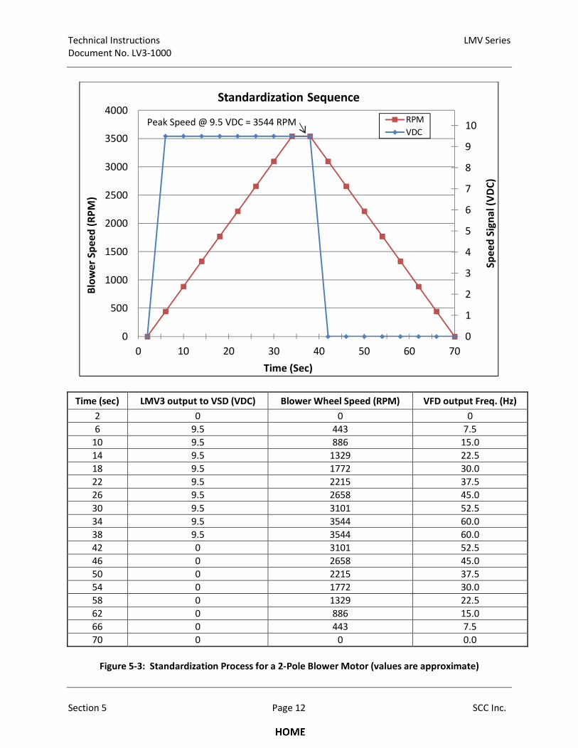
Technical Instructions LMV Series
Document No. LV3-1000
Section 5 Page 12 SCC Inc.
Time (sec) LMV3 output to VSD (VDC) Blower Wheel Speed (RPM) VFD output Freq. (Hz)
2 0 0 0
6 9.5 443 7.5
10 9.5 886 15.0
14 9.5 1329 22.5
18 9.5 1772 30.0
22 9.5 2215 37.5
26 9.5 2658 45.0
30 9.5 3101 52.5
34 9.5 3544 60.0
38 9.5 3544 60.0
42 0 3101 52.5
46 0 2658 45.0
50 0 2215 37.5
54 0 1772 30.0
58 0 1329 22.5
62 0 886 15.0
66 0 443 7.5
70 0 0 0.0
Figure 5-3: Standardization Process for a 2-Pole Blower Motor (values are approximate)
0
1
2
3
4
5
6
7
8
9
10
0
500
1000
1500
2000
2500
3000
3500
4000
0 10 20 30 40 50 60 70
Sp
ee
d S
ign
al
(VD
C)
Blo
we
r S
pe
ed
(R
PM
)
Time (Sec)
Standardization Sequence
RPM
VDCPeak Speed @ 9.5 VDC = 3544 RPM
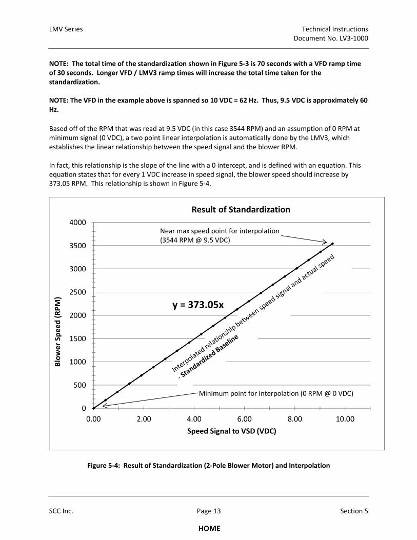
LMV Series Technical Instructions
Document No. LV3-1000
SCC Inc. Page 13 Section 5
NOTE: The total time of the standardization shown in Figure 5-3 is 70 seconds with a VFD ramp time
of 30 seconds. Longer VFD / LMV3 ramp times will increase the total time taken for the
standardization.
NOTE: The VFD in the example above is spanned so 10 VDC = 62 Hz. Thus, 9.5 VDC is approximately 60
Hz.
Based off of the RPM that was read at 9.5 VDC (in this case 3544 RPM) and an assumption of 0 RPM at
minimum signal (0 VDC), a two point linear interpolation is automatically done by the LMV3, which
establishes the linear relationship between the speed signal and the blower RPM.
In fact, this relationship is the slope of the line with a 0 intercept, and is defined with an equation. This
equation states that for every 1 VDC increase in speed signal, the blower speed should increase by
373.05 RPM. This relationship is shown in Figure 5-4.
Figure 5-4: Result of Standardization (2-Pole Blower Motor) and Interpolation
y = 373.05x
0
500
1000
1500
2000
2500
3000
3500
4000
0.00 2.00 4.00 6.00 8.00 10.00
Blo
we
r S
pe
ed
(R
PM
)
Speed Signal to VSD (VDC)
Result of Standardization
Near max speed point for interpolation
(3544 RPM @ 9.5 VDC)
Minimum point for Interpolation (0 RPM @ 0 VDC)
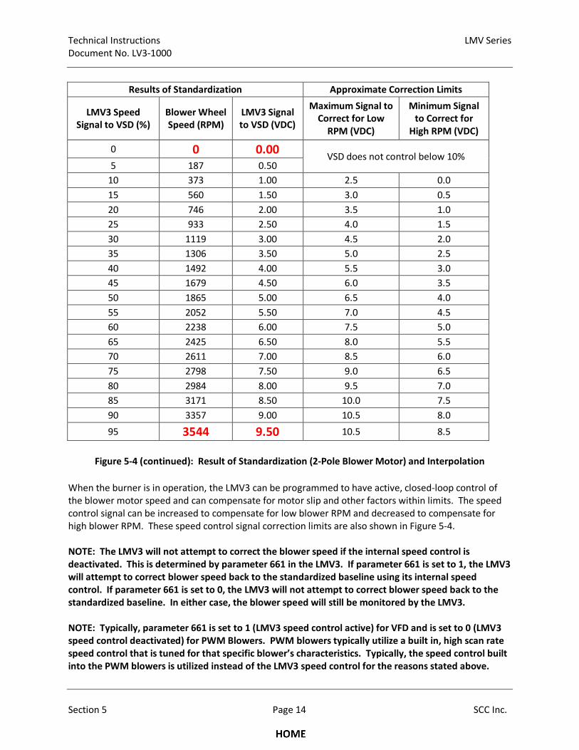
Technical Instructions LMV Series
Document No. LV3-1000
Section 5 Page 14 SCC Inc.
Results of Standardization Approximate Correction Limits
LMV3 Speed
Signal to VSD (%)
Blower Wheel
Speed (RPM)
LMV3 Signal
to VSD (VDC)
Maximum Signal to
Correct for Low
RPM (VDC)
Minimum Signal
to Correct for
High RPM (VDC)
0 0 0.00 VSD does not control below 10%
5 187 0.50
10 373 1.00 2.5 0.0
15 560 1.50 3.0 0.5
20 746 2.00 3.5 1.0
25 933 2.50 4.0 1.5
30 1119 3.00 4.5 2.0
35 1306 3.50 5.0 2.5
40 1492 4.00 5.5 3.0
45 1679 4.50 6.0 3.5
50 1865 5.00 6.5 4.0
55 2052 5.50 7.0 4.5
60 2238 6.00 7.5 5.0
65 2425 6.50 8.0 5.5
70 2611 7.00 8.5 6.0
75 2798 7.50 9.0 6.5
80 2984 8.00 9.5 7.0
85 3171 8.50 10.0 7.5
90 3357 9.00 10.5 8.0
95 3544 9.50 10.5 8.5
Figure 5-4 (continued): Result of Standardization (2-Pole Blower Motor) and Interpolation
When the burner is in operation, the LMV3 can be programmed to have active, closed-loop control of
the blower motor speed and can compensate for motor slip and other factors within limits. The speed
control signal can be increased to compensate for low blower RPM and decreased to compensate for
high blower RPM. These speed control signal correction limits are also shown in Figure 5-4.
NOTE: The LMV3 will not attempt to correct the blower speed if the internal speed control is
deactivated. This is determined by parameter 661 in the LMV3. If parameter 661 is set to 1, the LMV3
will attempt to correct blower speed back to the standardized baseline using its internal speed
control. If parameter 661 is set to 0, the LMV3 will not attempt to correct blower speed back to the
standardized baseline. In either case, the blower speed will still be monitored by the LMV3.
NOTE: Typically, parameter 661 is set to 1 (LMV3 speed control active) for VFD and is set to 0 (LMV3
speed control deactivated) for PWM Blowers. PWM blowers typically utilize a built in, high scan rate
speed control that is tuned for that specific blower’s characteristics. Typically, the speed control built
into the PWM blowers is utilized instead of the LMV3 speed control for the reasons stated above.
LMV Series Technical Instructions
Document No. LV3-1000
SCC Inc. Page 15 Section 5
If the speed control signal is increased to the maximum allowable signal and the blower RPM is still low,
an Error Code 83, Diagnostic Code 2 will be displayed on the AZL.
If the speed control signal is decreased to the minimum allowable signal and the blower RPM is still high,
an Error Code 83, Diagnostic Code 1 will be displayed on the AZL.
The reason that the standardization is done at 9.5 VDC instead of at 10 VDC is to give the LMV3 some
additional "room" to increase the speed control signal for a low RPM condition at high fire. Because the
standardization is done at 9.5 VDC, the analog input on the VFD is spanned so that 10 VDC = 62 Hz. This
is done so that the blower will still achieve full 60 Hz blower speed at high fire on jobs where the blower
is just large enough.
NOTE: Most VFDs can be scaled to output 400 Hz or more. Consult the blower and / or motor
manufacturer before over-speeding the motor and blower, since blower wheels and motor rotors can
catastrophically fail if RPM limits are exceeded.
In addition to limits on how much the speed control signal can be compensated, the LMV3 also has
limits on how far the blower speed can deviate from the standardized speed baseline. These blower
speed deviation limits are valid, independent of the activation or deactivation of the LMV3’s internal
speed control (parameter 661). The next section explains how the blower speed is monitored when the
burner is in operation.
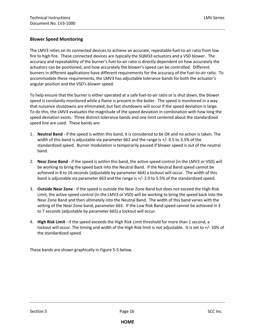
Technical Instructions LMV Series
Document No. LV3-1000
Section 5 Page 16 SCC Inc.
Blower Speed Monitoring
The LMV3 relies on its connected devices to achieve an accurate, repeatable fuel-to-air ratio from low
fire to high fire. These connected devices are typically the SQM33 actuators and a VSD blower. The
accuracy and repeatability of the burner’s fuel-to-air ratio is directly dependent on how accurately the
actuators can be positioned, and how accurately the blower’s speed can be controlled. Different
burners in different applications have different requirements for the accuracy of the fuel-to-air ratio. To
accommodate these requirements, the LMV3 has adjustable tolerance bands for both the actuator’s
angular position and the VSD’s blower speed.
To help ensure that the burner is either operated at a safe fuel-to-air ratio or is shut down, the blower
speed is constantly monitored while a flame is present in the boiler. The speed is monitored in a way
that nuisance shutdowns are eliminated, but fast shutdowns will occur if the speed deviation is large.
To do this, the LMV3 evaluates the magnitude of the speed deviation in combination with how long the
speed deviation exists. Three distinct tolerance bands and one limit centered about the standardized
speed line are used. These bands are:
1. Neutral Band - if the speed is within this band, it is considered to be OK and no action is taken. The
width of this band is adjustable via parameter 662 and the range is +/- 0.5 to 3.5% of the
standardized speed. Burner modulation is temporarily paused if blower speed is out of the neutral
band.
2. Near Zone Band - if the speed is within this band, the active speed control (in the LMV3 or VSD) will
be working to bring the speed back into the Neutral Band. If the Neutral Band speed cannot be
achieved in 8 to 16 seconds (adjustable by parameter 664) a lockout will occur. The width of this
band is adjustable via parameter 663 and the range is +/- 2.0 to 5.5% of the standardized speed.
3. Outside Near Zone - if the speed is outside the Near Zone Band but does not exceed the High Risk
Limit, the active speed control (in the LMV3 or VSD) will be working to bring the speed back into the
Near Zone Band and then ultimately into the Neutral Band. The width of this band varies with the
setting of the Near Zone band, parameter 663. If the Low Risk Band speed cannot be achieved in 3
to 7 seconds (adjustable by parameter 665) a lockout will occur.
4. High Risk Limit - if the speed exceeds the High Risk Limit threshold for more than 1 second, a
lockout will occur. The timing and width of the High Risk limit is not adjustable. It is set to +/- 10% of
the standardized speed.
These bands are shown graphically in Figure 5-5 below.
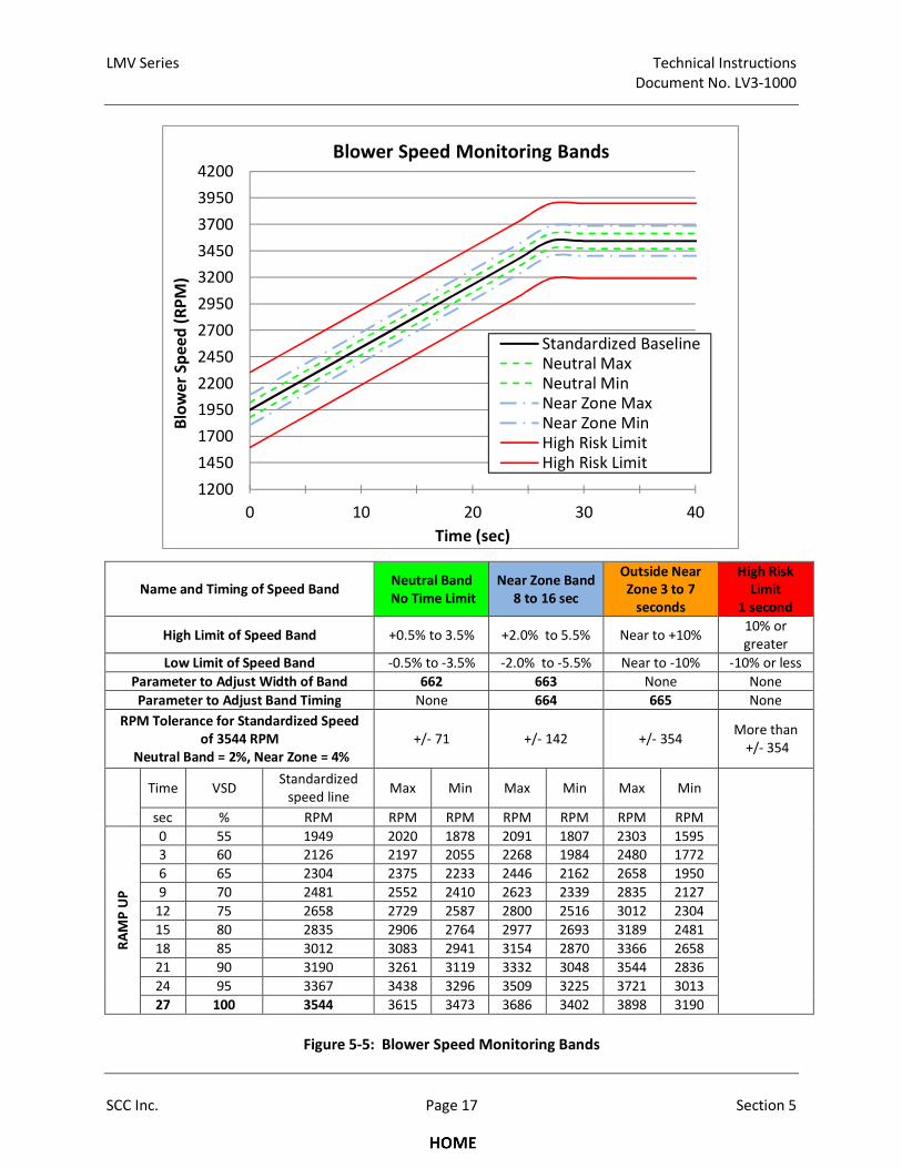
LMV Series Technical Instructions
Document No. LV3-1000
SCC Inc. Page 17 Section 5
Name and Timing of Speed Band Neutral Band
No Time Limit
Near Zone Band
8 to 16 sec
Outside Near
Zone 3 to 7
seconds
High Risk
Limit
1 second
High Limit of Speed Band +0.5% to 3.5% +2.0% to 5.5% Near to +10% 10% or
greater
Low Limit of Speed Band -0.5% to -3.5% -2.0% to -5.5% Near to -10% -10% or less
Parameter to Adjust Width of Band 662 663 None None
Parameter to Adjust Band Timing None 664 665 None
RPM Tolerance for Standardized Speed
of 3544 RPM
Neutral Band = 2%, Near Zone = 4%
+/- 71 +/- 142 +/- 354 More than
+/- 354
Time VSD Standardized
speed line Max Min Max Min Max Min
sec % RPM RPM RPM RPM RPM RPM RPM
RA
MP
UP
0 55 1949 2020 1878 2091 1807 2303 1595
3 60 2126 2197 2055 2268 1984 2480 1772
6 65 2304 2375 2233 2446 2162 2658 1950
9 70 2481 2552 2410 2623 2339 2835 2127
12 75 2658 2729 2587 2800 2516 3012 2304
15 80 2835 2906 2764 2977 2693 3189 2481
18 85 3012 3083 2941 3154 2870 3366 2658
21 90 3190 3261 3119 3332 3048 3544 2836
24 95 3367 3438 3296 3509 3225 3721 3013
27 100 3544 3615 3473 3686 3402 3898 3190
Figure 5-5: Blower Speed Monitoring Bands
1200
1450
1700
1950
2200
2450
2700
2950
3200
3450
3700
3950
4200
0 10 20 30 40
Blo
we
r S
pe
ed
(R
PM
)
Time (sec)
Standardized Baseline
Neutral Max
Neutral Min
Near Zone Max
Near Zone Min
High Risk Limit
High Risk Limit
Blower Speed Monitoring Bands
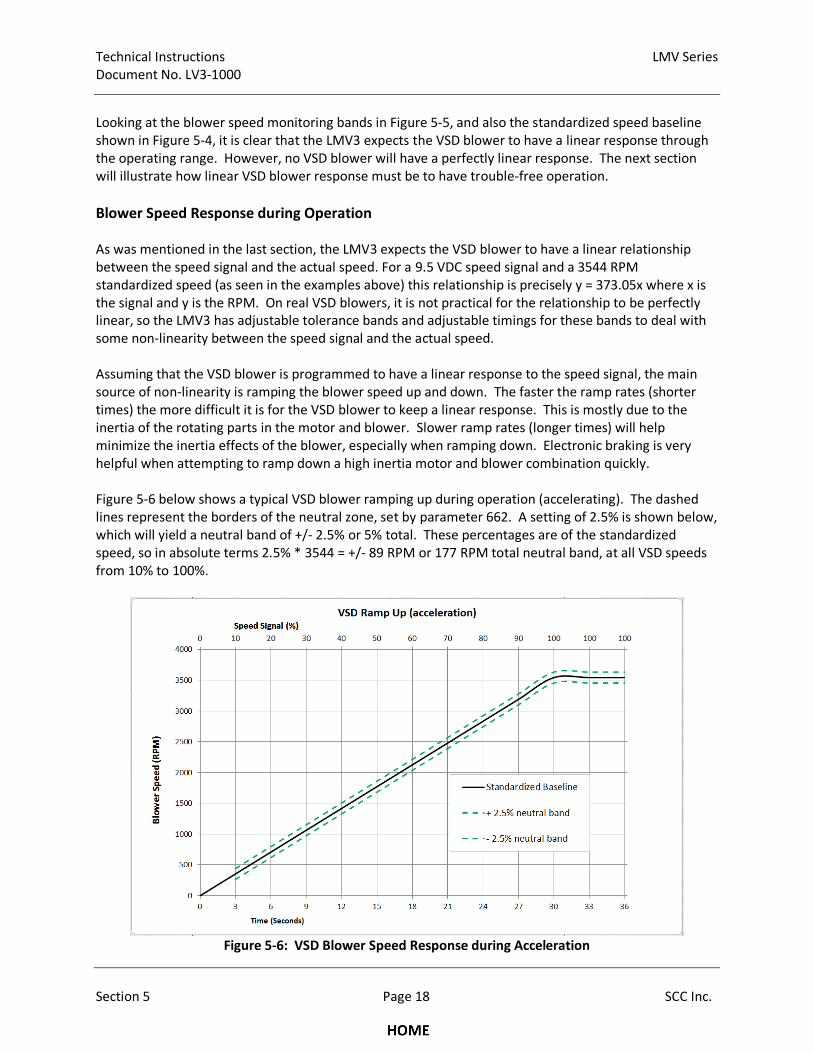
Technical Instructions LMV Series
Document No. LV3-1000
Section 5 Page 18 SCC Inc.
Looking at the blower speed monitoring bands in Figure 5-5, and also the standardized speed baseline
shown in Figure 5-4, it is clear that the LMV3 expects the VSD blower to have a linear response through
the operating range. However, no VSD blower will have a perfectly linear response. The next section
will illustrate how linear VSD blower response must be to have trouble-free operation.
Blower Speed Response during Operation
As was mentioned in the last section, the LMV3 expects the VSD blower to have a linear relationship
between the speed signal and the actual speed. For a 9.5 VDC speed signal and a 3544 RPM
standardized speed (as seen in the examples above) this relationship is precisely y = 373.05x where x is
the signal and y is the RPM. On real VSD blowers, it is not practical for the relationship to be perfectly
linear, so the LMV3 has adjustable tolerance bands and adjustable timings for these bands to deal with
some non-linearity between the speed signal and the actual speed.
Assuming that the VSD blower is programmed to have a linear response to the speed signal, the main
source of non-linearity is ramping the blower speed up and down. The faster the ramp rates (shorter
times) the more difficult it is for the VSD blower to keep a linear response. This is mostly due to the
inertia of the rotating parts in the motor and blower. Slower ramp rates (longer times) will help
minimize the inertia effects of the blower, especially when ramping down. Electronic braking is very
helpful when attempting to ramp down a high inertia motor and blower combination quickly.
Figure 5-6 below shows a typical VSD blower ramping up during operation (accelerating). The dashed
lines represent the borders of the neutral zone, set by parameter 662. A setting of 2.5% is shown below,
which will yield a neutral band of +/- 2.5% or 5% total. These percentages are of the standardized
speed, so in absolute terms 2.5% * 3544 = +/- 89 RPM or 177 RPM total neutral band, at all VSD speeds
from 10% to 100%.
Figure 5-6: VSD Blower Speed Response during Acceleration
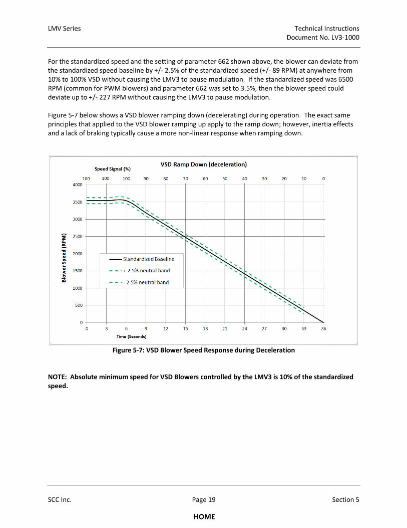
LMV Series Technical Instructions
Document No. LV3-1000
SCC Inc. Page 19 Section 5
For the standardized speed and the setting of parameter 662 shown above, the blower can deviate from
the standardized speed baseline by +/- 2.5% of the standardized speed (+/- 89 RPM) at anywhere from
10% to 100% VSD without causing the LMV3 to pause modulation. If the standardized speed was 6500
RPM (common for PWM blowers) and parameter 662 was set to 3.5%, then the blower speed could
deviate up to +/- 227 RPM without causing the LMV3 to pause modulation.
Figure 5-7 below shows a VSD blower ramping down (decelerating) during operation. The exact same
principles that applied to the VSD blower ramping up apply to the ramp down; however, inertia effects
and a lack of braking typically cause a more non-linear response when ramping down.
Figure 5-7: VSD Blower Speed Response during Deceleration
NOTE: Absolute minimum speed for VSD Blowers controlled by the LMV3 is 10% of the standardized
speed.
Technical Instructions LMV Series
Document No. LV3-1000
Section 5 Page 20 SCC Inc.
Suggested Setup Procedure for the VSD Control – Parallel Positioning Application
After verifying that all VSD blower-related components are installed and wired correctly, the LMV3
control can be programmed for the VSD blower application. Naturally, this must be done before the
Ratio Control Curves are commissioned.
This procedure will cover two types of VSD. Setup of a variable frequency drive (VFD) with a three phase
motor will be covered, as well as a brushless DC (PWM) blower.
Prerequisites
For three phase motors with a VFD:
• The arrow on the speed wheel must point in the same direction as the correct blower rotation.
• The gap between the inductive speed sensor and the speed wheel finger is correct (approx. 1/16").
• The VFD, motor, and LMV3 share a common ground.
• The analog signal from the LMV3 to the VFD must be in shielded cable with one end of the shield
grounded.
• The VFD is programmed correctly (see “Configuring VFDs for use with the LMV3”) earlier in this
section for guidance.
For brushless DC blowers (PWM blowers):
• Ensure that the PWM blower is a closed loop type, meaning that it is utilizing an on-board speed
control properly tuned for that specific blower.
• Ensure that the maximum closed loop speed that the PWM blower is programmed for is adequate
for the application.
• Ensure the wiring is correct, paying particular attention to the low voltage wiring. Some PWM
blowers have their electronics internally powered from the high voltage, while others require
separate, external low voltage power.
After these points are double-checked, the LMV3 parameters can be set for the application.
1. Set the VSD ramp times.
a. Ramp up = Parameter 522
b. Ramp down = Parameter 523
c. Modulation ramp = Parameter 544
These ramp times must be set at least 10% longer than the capabilities of the connected VSD. For
example, if the VSD can ramp up is 25 seconds, then parameter 522 must be set to at least 27 seconds.
The same logic applies for the ramp down, parameter 523. The modulation ramp has a minimum setting
of 32 seconds. If parameters 522 or 523 are more than 32 seconds, match the setting of parameter 544
to the longer ramp time which will be the value of 522 or 523.
LMV Series Technical Instructions
Document No. LV3-1000
SCC Inc. Page 21 Section 5
2. Determine if separate ramping of VSD and air damper is necessary when driving from pre-purge to
ignition. If separate ramping is used, the air damper stays at pre-purge position while the VSD
ramps down to ignition position. This has a braking effect on the blower, and is very useful for PWM
blowers and VFD without braking resistors. The disadvantage is a slightly longer start up time.
RECOMMENDATION: If a PWM blower or a VFD without a braking resistor is being used, set
parameter 529 to 2, which utilizes the separate ramping and also allows for 50% more speed
tolerance before the main fuel valves are open.
3. Set parameter 542 to 1, which activates the VSD control functionality in the LMV3. This is necessary
for any type of VSD that will be used with the LMV3.
4. Determine the type of speed feedback (tachometer) that will be used with the LMV3. When the
VSD is part of a non-pneumatic parallel positioning burner control, speed feedback is required.
a. For VFD with three phase blowers that utilize a speed wheel kit for speed feedback, set
parameter 643 to 0, which indicates an asymmetric pulse pattern that matches the speed
wheel kit. This speed wheel kit also produces 3 pulses per revolution, so ensure that
parameter 644 is set to 3.
b. For PWM blowers that utilize the internal Hall Effect sensors, set parameter 643 to 1, which
indicates an equally spaced symmetric pulse pattern. A symmetric pulse pattern is used by
most PWM blower manufacturers. The number of pulses per revolution varies by model
and manufacturer, but is typically 2 or 3 pulses per revolution. Determine the number of
pulses per revolution, and set parameter 644 for this number. Parameter 644 can be set for
1 to 6 pulses per revolution.
5. Determine if it is permissible for the blower wheel to coast from post purge speed down to home
position speed, which is typically 0% VSD. If the blower wheel is permitted to coast, the LMV3 will
take slightly longer to get to home position which may be a concern if the burner needs to come
back on immediately.
RECOMMENDATION: If a PWM blower or a VFD without a braking resistor is being used, set
parameter 653 to 0, allowing the VSD to coast down after post purge. Setting parameter 653 to 1
will ramp the VSD to home position more quickly, but may also cause VSD issues if braking is not
used.
6. Set parameter 661 to activate or deactivate the LMV3 internal speed control.
a. For VFDs with three phase blowers, parameter 661 is typically set to 1, which keeps the
LMV3 internal speed control activated.
b. For PWM blowers, especially those utilizing a properly tuned onboard speed control,
parameter 661 is typically set to 0, which turns off the speed control inside the LMV3.
Technical Instructions LMV Series
Document No. LV3-1000
Section 5 Page 22 SCC Inc.
7. Set the VSD blower speed monitoring bands to values that are safe for the application. See
complete explanation of these bands detailed earlier in this section
a. VFDs with three phase blowers are typically more accurate from a speed control standpoint,
especially if a vector type of VFD is used. For a vector type VFD driving a three phase
blower, the neutral band (parameter 662) and the near band (parameter 663) can typically
be left at their lowest values of 662 = 0.5% and 663 = 2%. If the application in question does
not require fuel-to-air ratio control that is this precise, the neutral band and the near band
can be increased. Maximum values of 662 = 3.5% and 663 = 5.5% are seldom needed if a
VFD and three phase blower are functioning properly.
b. PWM blowers are somewhat less accurate from a speed control standpoint, but still have
adequate accuracy for most applications. When using a PWM blower, the neutral band
(parameter 662) and the near band (parameter 663) are typically set at values of 662 = 2.5%
and 663 = 4.5%, assuming that it is safe to have this amount of fuel-to-air ratio control
variance in the application. Maximum values of 662 = 3.5% and 663 = 5.5% are occasionally
needed for PWM blowers if they are not correctly programmed for the application.
8. Set the pre-purge position of the air actuator, which is typically the same as the high fire position of
the air actuator. This is set with either parameter 502, index 01 for fuel 0, or parameter 505, index
01 for fuel 1.
9. Ensure that the safety loop is closed, and that the main power is turned on to the VSD. Also ensure
that the burner switch is off. Start the standardization procedure by setting parameter 641 to 1.
See complete explanation of the standardization procedure earlier in this section.
10. After the standardization is completed successfully, parameter 641 will return to 0 and “OFF UPR”
will be displayed on the AZL. If a value appears other than 0, see Error Code 82 in Section 6 of this
manual for the cause of the error.
11. If desired, the standardized speed that was recorded during the standardization procedure can be
viewed under parameter 642, index 01 and index 02.
12. After the standardization has been completed successfully, the VSD is now ready to run and the fuel-
to-air ratio curves can be set.
LMV Series Technical Instructions
Document No. LV3-1000
SCC Inc. Page 23 Section 5
Suggested Setup Procedure for the VSD Speed Shift
The LMV3 also features a VSD speed shift, which enables the VSD speed curve to be shifted up or down
a limited amount at any point on the fuel-to-air ratio control curve. This feature enables the LMV3 to
accept a 4-20mA signal from an external device to shift the VSD speed, which “trims” the fuel-to-air
ratio.
This VSD speed shift is typically used to trim the fuel-to-air ratio in response to burner intake air
temperature and / or %O2 in the burner exhaust. Taking this into consideration, an external controller
that reads burner intake air temperature and / or %O2 in the burner exhaust and outputs a 4-20mA
signal to the LMV3 is typically used to command the VSD speed shift. Hard limits on the VSD speed shift
are programmable in the LMV3 so that a partial or complete failure of the 4-20mA signal will not cause
an unsafe fuel-to-air ratio.
The 4-20mA signal can also be used to shift the ignition speed of the VSD, so that the ignition point can
be made richer or leaner if desired.
The following pages detail how to set up and use the VSD speed shift on the LMV3.
Prerequisites
• If the 4-20mA analog input is employed for speed shift, it cannot be used for load control. When the
4-20mA signal is employed for speed shift, the firing rate command must be sent to the LMV3 in a
different way. For the LMV36, the firing rate must be controlled via Modbus. For the LMV37, the
firing rate must be controlled via Modbus or a floating bumping (3 point) signal.
• The fuel-to-air ratio control curves must be fully commissioned (see Section 4 – Commissioning)
before the VSD speed shift is activated. Care must be taken to allow for enough “room” at P1 and at
P9 for the VSD speed shift. For example, if +/- 10% VSD speed shift will be used, P1 low fire cannot
be lower than 20% VSD (10% is the absolute minimum setting for the VSD) and P9 high fire cannot
be higher than 90% VSD (100% is the absolute maximum setting for the VSD).
• When commissioning the fuel-to-air ratio control curves, a linear increase in fuel flow from low fire
(P1) to high fire (P9) is highly recommended, especially if the VSD speed shift will be used for O2
trim.
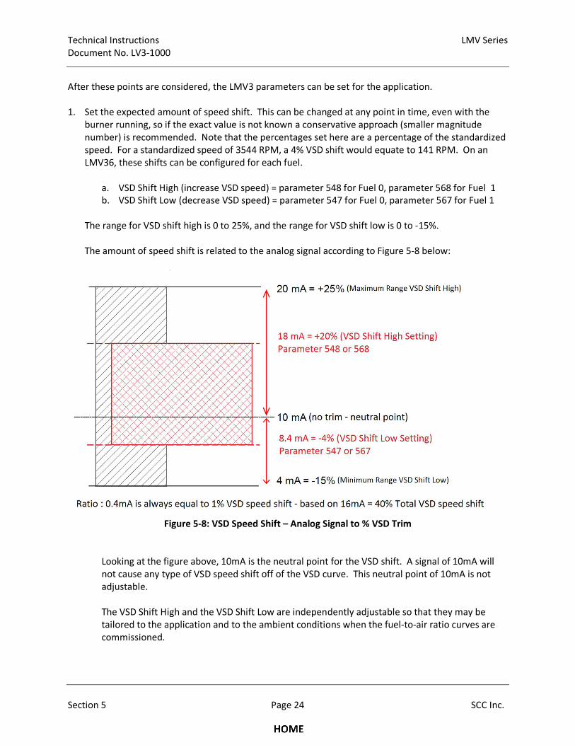
Technical Instructions LMV Series
Document No. LV3-1000
Section 5 Page 24 SCC Inc.
After these points are considered, the LMV3 parameters can be set for the application.
1. Set the expected amount of speed shift. This can be changed at any point in time, even with the
burner running, so if the exact value is not known a conservative approach (smaller magnitude
number) is recommended. Note that the percentages set here are a percentage of the standardized
speed. For a standardized speed of 3544 RPM, a 4% VSD shift would equate to 141 RPM. On an
LMV36, these shifts can be configured for each fuel.
a. VSD Shift High (increase VSD speed) = parameter 548 for Fuel 0, parameter 568 for Fuel 1
b. VSD Shift Low (decrease VSD speed) = parameter 547 for Fuel 0, parameter 567 for Fuel 1
The range for VSD shift high is 0 to 25%, and the range for VSD shift low is 0 to -15%.
The amount of speed shift is related to the analog signal according to Figure 5-8 below:
Figure 5-8: VSD Speed Shift – Analog Signal to % VSD Trim
Looking at the figure above, 10mA is the neutral point for the VSD shift. A signal of 10mA will
not cause any type of VSD speed shift off of the VSD curve. This neutral point of 10mA is not
adjustable.
The VSD Shift High and the VSD Shift Low are independently adjustable so that they may be
tailored to the application and to the ambient conditions when the fuel-to-air ratio curves are
commissioned.
LMV Series Technical Instructions
Document No. LV3-1000
SCC Inc. Page 25 Section 5
Changing the VSD Shift High and the VSD Shift Low values limits the amount of trim. This is done
by cutting down the range of the 4-20mA signal, not re-spanning the 4-20mA signal. In other
words, each 0.4mA of signal change will always equal 1% VSD trim. This relationship always
holds true and is completely independent of the setting of VSD Shift High and VSD Shift Low.
2. Set the VSD shift attenuation. This parameter is used to limit the amount of VSD shift at points
lower than high fire (P9). A setting of 100% means maximum shift attenuation (there will be no shift
at low fire and maximum shift at high fire). A setting of 0% means no shift attenuation (the amount
of shift at any point (P1 thru P9) will be the same as is commanded by the 4-20mA signal). This can
also be changed at any point in time, even with the burner running, so if the exact value is not
known a conservative approach (a higher value) is recommended.
a. VSD Shift Attenuation = parameter 549 for Fuel 0, parameter 569 for Fuel 1
3. Set the VSD shift delay. This parameter is used to delay the VSD shift after ignition. The timing for
this parameter starts after the LMV3 reaches phase 60. If the ignition speed shift is also being used,
the amount of VSD shift used for ignition will be retained until this delay times out. This delay can be
used to give the O2 sensor time to obtain a valid reading after light off, or it can be used to run the
burner rich for a set period of time after ignition to heat up the burner mesh or combustion
chamber. The range is 0 to 255 seconds.
a. VSD Shift Delay = parameter 550 for Fuel 0, parameter 570 for Fuel 1
4. Set the Shift Limit Response. This parameter determines the reaction of the LMV3 when the shift
limits (VSD Shift Low and VSD Shift High) are reached. Three options are available (0 = warning only,
1 = warning and VSD shift deactivation, 2 = burner shutdown).
a. Shift Limit Response = parameter 552 for Fuel 0, parameter 572 for Fuel 1
5. Set the Shift Limit Time. This parameter serves as a buffer timer for the selected Shift Limit
Response. Whichever action is selected by the Shift Limit Response, this will delay that action for
the set amount of time. The range is 0-3600 seconds (60 minutes). A setting of 0 will deactivate the
feature.
a. Shift Limit Time = parameter 551 for Fuel 0, parameter 571 for Fuel 1
6. Set the LMV3 response for an out of range (invalid) 4-20mA signal. Three options are available (0 =
no VSD speed shift (warning message displayed), 1 = lockout, 2 = no VSD speed shift (warning
message displayed).
a. Invalid Analog In = parameter 204
7. Now that the VSD speed shift is configured, it can be activated. Five different options are available
(0 = deactivated, 1 = activated, 2 = activated with analog input test, 3 = activated with ignition speed
shift, 4 = activated with analog input test and ignition speed shift).
a. VSD Speed Shift = parameter 530
Technical Instructions LMV Series
Document No. LV3-1000
Section 5 Page 26 SCC Inc.
When set to Options 1 or 2 (activated or activated with analog input test), the VSD speed will be
shifted from the base VSD curve using the 4-20mA analog signal. This shift will occur when the
LMV3 reaches phase 60, and the shift delay (parameter 550/570) has timed out. The shift will
remain in effect until the end of phase 62 when the fuel valves close. Note that if the 4-20mA
analog signal stays at 10mA, no shift will be observed.
When set to Options 3 or 4 (activated with ignition speed shift or activated with analog input test
and ignition speed shift), the VSD speed will be shifted from the base VSD curve using the 4-20mA
analog signal. With these options, the shift has two parts. The first part is the ignition speed shift,
which is determined by the 4-20mA signal applied to the LMV3 during the end of phase 30
(prepurge). Once the LMV3 leaves phase 30, this amount of speed shift will be locked in for ignition
positon (P0). This amount of speed shift will continue until the LMV3 reaches phase 60, and the
shift delay (parameter 550/570) has timed out. After this timeout, the LMV3 will respond to the
current 4-20mA analog signal and shift the VSD speed accordingly.
Just like the previous modes, the shift will remain in effect until the end of phase 62 when the fuel
valves close. Note that if the 4-20mA analog signal stays at 10mA, no shift will be observed.
Options 2 and 4 add an analog input test to the functionality stated above. The analog input test is
an added requirement that must be satisfied on each start up so that the correct functionality of the
PLC or other device can be verified by the LMV3. The analog input test consists of the PLC or other
device sending a 10mA signal to the LMV3 in standby (phase 12) and a 4mA signal during traveling
to pre-purge (phase 24) for the first 2 seconds of pre-purge (phase 30). This would be accomplished
by the PLC or other device reading the LMV3 phase over Modbus, and then generating the
appropriate analog signal to match the phase.
8. After the VSD speed shift is activated, it is highly recommended to test the VSD shift settings,
especially if the settings are unproven for the application. This can be done by varying the 4-20mA
analog signal to the LMV3, and carefully approaching the VSD Shift High and VSD Shift Low limits.
This test should be done at each point (P1 – low fire, P2, P3, P4, up to P9 – high fire) to ensure that
the VSD Shift High and VSD Shift Low limits are safe for the application and that an unsafe fuel-to-air
ratio will not occur at these shift limits. It is also very likely that the VSD shift attenuation
(parameter 549/569) will need to be adjusted, since most applications require less VSD shift at low
fire to achieve a certain fuel-to-air ratio.
9. If ignition speed shift is utilized (Options 3 or 4), this should also be tested at VSD Shift High and VSD
Shift Low limits to ensure safe fuel-to-air ratios at light-off.
NOTE: It is the responsibility of the technician commissioning the VSD speed shift to ensure safe fuel-
to-air ratios at all points (P0 to P9) for the settings of VSD Shift High (parameter 548/568), VSD Shift
Low (parameter 547/567) and VSD Shift Attenuation (parameter 549/569). If settings of these
parameters are unproven for the application, tests at the VSD shift limits at each point (P0 to P9) must
be done.
LMV Series Technical Instructions
Document No. LV3-1000
SCC Inc. Page 27 Section 5
Additional Tips for Burners with VSD Speed Shift
• The VSD speed shift occurs rather slowly. The rate at which the shift occurs is 1% VSD shift every 2
seconds until the targeted shift is reached. If the VSD speed shift is used as part of an O2 trim
system, this must be taken into account.
• As an alternative to activating the analog input test, a PLC or other device can be set up to read back
the amount of VSD trim via LMV3 Modbus register 148, thereby creating closed loop feedback on
the VSD speed shift system. If the PLC or other device detects a problem with what is being fed back
over this register, the PLC or other device can take corrective action (adjust signal, shut down, or
lockout the burner, etc.)
• If the PLC or other device that is sending the 4-20mA VSD speed shift command to the LMV3 has a PI
(Proportional + Integral) loop linking the speed shift command to a measured value and a set point,
PI “windup” is a concern. If the PLC or other device is up against one of the LMV3 trim limits
unknowingly, PI windup is almost a certainty. To address this issue, additional Modbus registers
have been added so that the PLC or other device can read back the trim limits programmed into the
LMV3. These registers are: 144 – Lower trim limit Fuel 0, 145 – Upper trim limit Fuel 0, 146 – Lower
trim limit Fuel 1, 147 – Upper trim limit Fuel 1
• The ignition speed shift is typically used to make the fuel-to-air ratio more fuel rich at light off and
during the transition from light off (P0) to low fire (P1). Running the burner richer typically helps
burner stability, especially when the burner head and / or combustion chamber is cold.

Technical Instructions LMV Series
Document No. LV3-1000
Section 5 Page 28 SCC Inc.
Additional Tips for Burners with VSD Control
• Most of the time, speed faults that are seen on the LMV3 are caused by the VFD not being able to
decelerate the blower quickly enough when the blower is being ramped down. If fast ramp times
are not critical for the application, ramp times can be increased and this should correct the issue. If
fast ramp times are necessary, a braking resistor or other means of braking may be required to
achieve the fast ramp down times.
• The LMV3 in combination with the VSD can be tested to check for proper operation while the LMV3
is in standby, phase 12. After the VSD is successfully standardized, the home position of the VSD can
be adjusted with parameter 503 or 506, index 00. The actual speed in RPM can be read back on
parameter 935. If different % VSD speeds are set (503 or 506) and plotted vs. the actual speed
(935), the linearity of the VSD speed response can be assessed.
• The absolute speed as read in real time by the LMV3 can be viewed at any point during operation
using parameter 935. Many other parameters that are useful for troubleshooting are also contained
in the 900-level parameters.
• The ACS410 PC software has a trending package that is very useful when diagnosing VSD speed
control issues. In particular, the commanded speed and the actual speed can be plotted against one
another real time, and can be accurately reviewed to see where the largest deviations occur.
• The combustion air pressure switch should be set by taking the VSD to 10% below the lowest
anticipated low fire speed (if low fire is 50%, take the VSD to 40%) and setting the switch to open at
that point. This should maximize the safety potential of the combustion air pressure switch and
minimize nuisance air pressure trips. This can be done in standby by setting the home position of
the VSD to 10% lower than low fire and adjusting the switch to trip at this point.
• In most applications with an air damper, there is little reason to decrease blower speed below about
50% VSD (30 Hz for VFD). Power consumption decreases by the cube of the RPM even without the
additional restriction of an air damper. Referencing information from the "Centrifugal Blower
Fundamentals" section on the previous pages, decreasing the speed of a 25 HP (18.62 kW) motor
from 3600 RPM (60 Hz) to 1800 RPM (30 Hz) will cause the power consumption to be reduced from
18.62 kW down to 2.32 kW, an electrical savings of over 800%.
• A VSD alone without an air damper or sliding head offers limited accuracy and repeatability for the
airflow at higher burner turndowns. For most boiler burners, modulating the VSD alone without an
air damper is okay for turndowns of 4-to-1 or less. Using only a VSD for airflow regulation at higher
turndowns may lead to airflow repeatability issues.

Section 1 Overview
Section 2 Wiring
Section 3 Parameters
Section 4 Commissioning
Section 5 VSD
Section 6 Troubleshooting
Section 7 Modbus
Section 8 ACS410
Appendix A Application Guide
Section 1 Overview
Section 2 Wiring
Section 3 Parameters
Section 4 Commissioning
Section 5 VSD
Section 6 Troubleshooting
Section 7 Modbus
Section 8 ACS410
Appendix A Application Guide
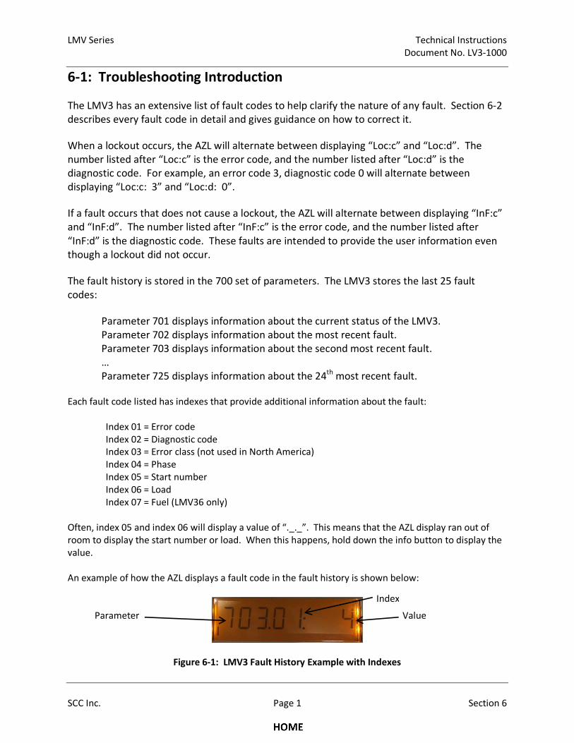
LMV Series Technical Instructions
Document No. LV3-1000
SCC Inc. Page 1 Section 6
6-1: Troubleshooting Introduction
The LMV3 has an extensive list of fault codes to help clarify the nature of any fault. Section 6-2
describes every fault code in detail and gives guidance on how to correct it.
When a lockout occurs, the AZL will alternate between displaying “Loc:c” and “Loc:d”. The
number listed after “Loc:c” is the error code, and the number listed after “Loc:d” is the
diagnostic code. For example, an error code 3, diagnostic code 0 will alternate between
displaying “Loc:c: 3” and “Loc:d: 0”.
If a fault occurs that does not cause a lockout, the AZL will alternate between displaying “InF:c”
and “InF:d”. The number listed after “InF:c” is the error code, and the number listed after
“InF:d” is the diagnostic code. These faults are intended to provide the user information even
though a lockout did not occur.
The fault history is stored in the 700 set of parameters. The LMV3 stores the last 25 fault
codes:
Parameter 701 displays information about the current status of the LMV3.
Parameter 702 displays information about the most recent fault.
Parameter 703 displays information about the second most recent fault.
…
Parameter 725 displays information about the 24th
most recent fault.
Each fault code listed has indexes that provide additional information about the fault:
Index 01 = Error code
Index 02 = Diagnostic code
Index 03 = Error class (not used in North America)
Index 04 = Phase
Index 05 = Start number
Index 06 = Load
Index 07 = Fuel (LMV36 only)
Often, index 05 and index 06 will display a value of “._._”. This means that the AZL display ran out of
room to display the start number or load. When this happens, hold down the info button to display the
value.
An example of how the AZL displays a fault code in the fault history is shown below:
Figure 6-1: LMV3 Fault History Example with Indexes
Parameter Value
Index
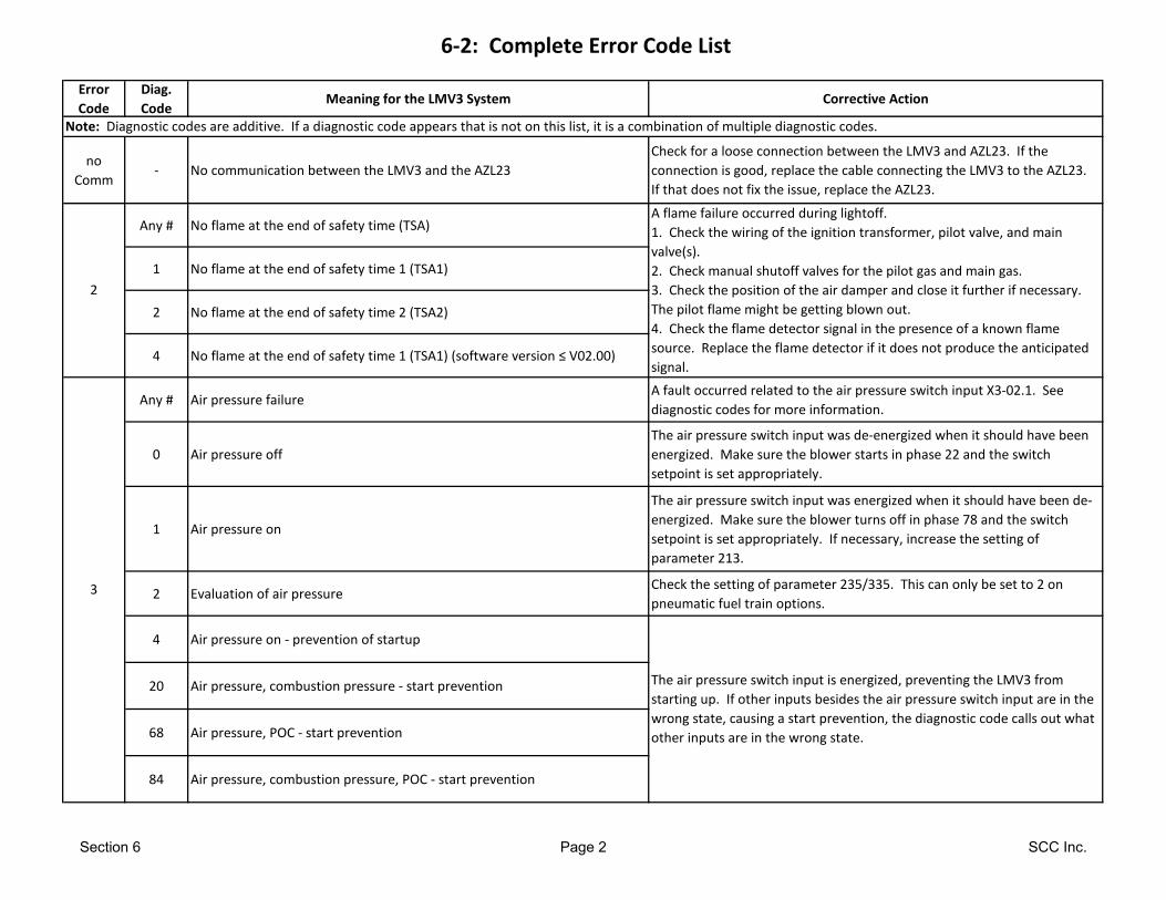
6-2: Complete Error Code List
Error
Code
Diag.
CodeMeaning for the LMV3 System Corrective Action
no
Comm- No communication between the LMV3 and the AZL23
Check for a loose connection between the LMV3 and AZL23. If the
connection is good, replace the cable connecting the LMV3 to the AZL23.
If that does not fix the issue, replace the AZL23.
Any # No flame at the end of safety time (TSA)
1 No flame at the end of safety time 1 (TSA1)
2 No flame at the end of safety time 2 (TSA2)
4 No flame at the end of safety time 1 (TSA1) (software version ≤ V02.00)
Any # Air pressure failureA fault occurred related to the air pressure switch input X3-02.1. See
diagnostic codes for more information.
0 Air pressure off
The air pressure switch input was de-energized when it should have been
energized. Make sure the blower starts in phase 22 and the switch
setpoint is set appropriately.
1 Air pressure on
The air pressure switch input was energized when it should have been de-
energized. Make sure the blower turns off in phase 78 and the switch
setpoint is set appropriately. If necessary, increase the setting of
parameter 213.
2 Evaluation of air pressureCheck the setting of parameter 235/335. This can only be set to 2 on
pneumatic fuel train options.
4 Air pressure on - prevention of startup
20 Air pressure, combustion pressure - start prevention
68 Air pressure, POC - start prevention
84 Air pressure, combustion pressure, POC - start prevention
Note: Diagnostic codes are additive. If a diagnostic code appears that is not on this list, it is a combination of multiple diagnostic codes.
3
The air pressure switch input is energized, preventing the LMV3 from
starting up. If other inputs besides the air pressure switch input are in the
wrong state, causing a start prevention, the diagnostic code calls out what
other inputs are in the wrong state.
2
A flame failure occurred during lightoff.
1. Check the wiring of the ignition transformer, pilot valve, and main
valve(s).
2. Check manual shutoff valves for the pilot gas and main gas.
3. Check the position of the air damper and close it further if necessary.
The pilot flame might be getting blown out.
4. Check the flame detector signal in the presence of a known flame
source. Replace the flame detector if it does not produce the anticipated
signal.
Section 6 Page 2 SCC Inc.
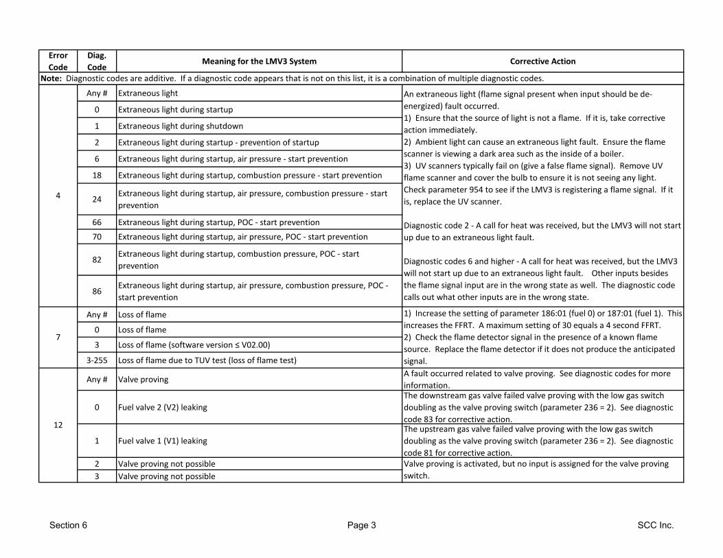
Error
Code
Diag.
CodeMeaning for the LMV3 System Corrective Action
Note: Diagnostic codes are additive. If a diagnostic code appears that is not on this list, it is a combination of multiple diagnostic codes.
Any # Extraneous light
0 Extraneous light during startup
1 Extraneous light during shutdown
2 Extraneous light during startup - prevention of startup
6 Extraneous light during startup, air pressure - start prevention
18 Extraneous light during startup, combustion pressure - start prevention
24Extraneous light during startup, air pressure, combustion pressure - start
prevention
66 Extraneous light during startup, POC - start prevention
70 Extraneous light during startup, air pressure, POC - start prevention
82Extraneous light during startup, combustion pressure, POC - start
prevention
86Extraneous light during startup, air pressure, combustion pressure, POC -
start prevention
Any # Loss of flame
0 Loss of flame
3 Loss of flame (software version ≤ V02.00)
3-255 Loss of flame due to TUV test (loss of flame test)
Any # Valve provingA fault occurred related to valve proving. See diagnostic codes for more
information.
0 Fuel valve 2 (V2) leaking
The downstream gas valve failed valve proving with the low gas switch
doubling as the valve proving switch (parameter 236 = 2). See diagnostic
code 83 for corrective action.
1 Fuel valve 1 (V1) leaking
The upstream gas valve failed valve proving with the low gas switch
doubling as the valve proving switch (parameter 236 = 2). See diagnostic
code 81 for corrective action.
2 Valve proving not possible
3 Valve proving not possible
An extraneous light (flame signal present when input should be de-
energized) fault occurred.
1) Ensure that the source of light is not a flame. If it is, take corrective
action immediately.
2) Ambient light can cause an extraneous light fault. Ensure the flame
scanner is viewing a dark area such as the inside of a boiler.
3) UV scanners typically fail on (give a false flame signal). Remove UV
flame scanner and cover the bulb to ensure it is not seeing any light.
Check parameter 954 to see if the LMV3 is registering a flame signal. If it
is, replace the UV scanner.
Diagnostic code 2 - A call for heat was received, but the LMV3 will not start
up due to an extraneous light fault.
Diagnostic codes 6 and higher - A call for heat was received, but the LMV3
will not start up due to an extraneous light fault. Other inputs besides
the flame signal input are in the wrong state as well. The diagnostic code
calls out what other inputs are in the wrong state.
12
1) Increase the setting of parameter 186:01 (fuel 0) or 187:01 (fuel 1). This
increases the FFRT. A maximum setting of 30 equals a 4 second FFRT.
2) Check the flame detector signal in the presence of a known flame
source. Replace the flame detector if it does not produce the anticipated
signal.
Valve proving is activated, but no input is assigned for the valve proving
switch.
7
4
Section 6 Page 3 SCC Inc.
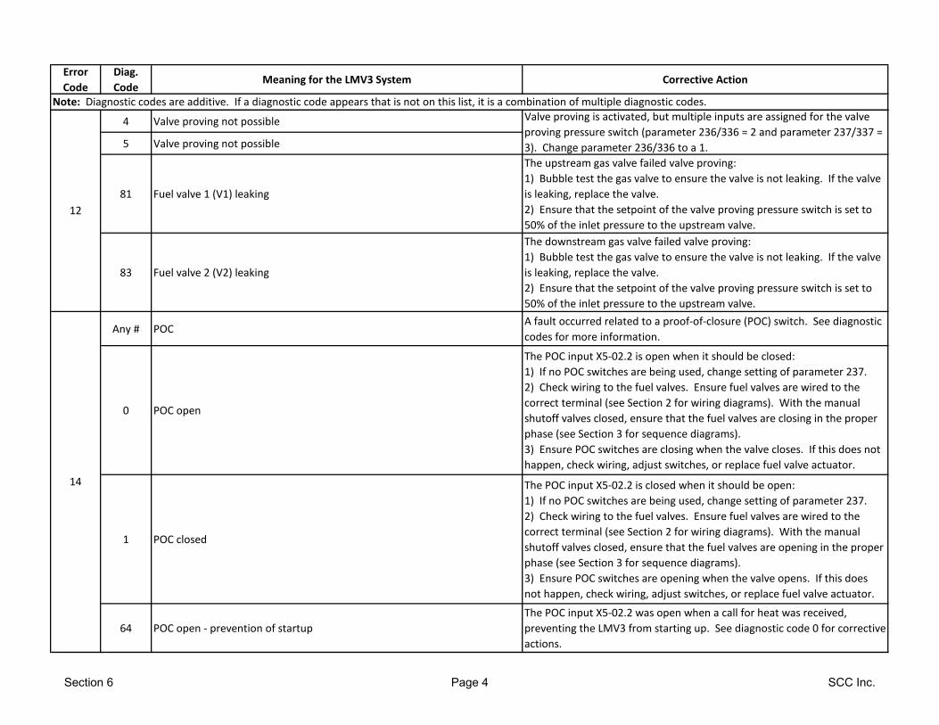
Error
Code
Diag.
CodeMeaning for the LMV3 System Corrective Action
Note: Diagnostic codes are additive. If a diagnostic code appears that is not on this list, it is a combination of multiple diagnostic codes.
4 Valve proving not possible
5 Valve proving not possible
81 Fuel valve 1 (V1) leaking
The upstream gas valve failed valve proving:
1) Bubble test the gas valve to ensure the valve is not leaking. If the valve
is leaking, replace the valve.
2) Ensure that the setpoint of the valve proving pressure switch is set to
50% of the inlet pressure to the upstream valve.
83 Fuel valve 2 (V2) leaking
The downstream gas valve failed valve proving:
1) Bubble test the gas valve to ensure the valve is not leaking. If the valve
is leaking, replace the valve.
2) Ensure that the setpoint of the valve proving pressure switch is set to
50% of the inlet pressure to the upstream valve.
Any # POCA fault occurred related to a proof-of-closure (POC) switch. See diagnostic
codes for more information.
0 POC open
The POC input X5-02.2 is open when it should be closed:
1) If no POC switches are being used, change setting of parameter 237.
2) Check wiring to the fuel valves. Ensure fuel valves are wired to the
correct terminal (see Section 2 for wiring diagrams). With the manual
shutoff valves closed, ensure that the fuel valves are closing in the proper
phase (see Section 3 for sequence diagrams).
3) Ensure POC switches are closing when the valve closes. If this does not
happen, check wiring, adjust switches, or replace fuel valve actuator.
1 POC closed
The POC input X5-02.2 is closed when it should be open:
1) If no POC switches are being used, change setting of parameter 237.
2) Check wiring to the fuel valves. Ensure fuel valves are wired to the
correct terminal (see Section 2 for wiring diagrams). With the manual
shutoff valves closed, ensure that the fuel valves are opening in the proper
phase (see Section 3 for sequence diagrams).
3) Ensure POC switches are opening when the valve opens. If this does
not happen, check wiring, adjust switches, or replace fuel valve actuator.
64 POC open - prevention of startup
The POC input X5-02.2 was open when a call for heat was received,
preventing the LMV3 from starting up. See diagnostic code 0 for corrective
actions.
12
Valve proving is activated, but multiple inputs are assigned for the valve
proving pressure switch (parameter 236/336 = 2 and parameter 237/337 =
3). Change parameter 236/336 to a 1.
14
Section 6 Page 4 SCC Inc.
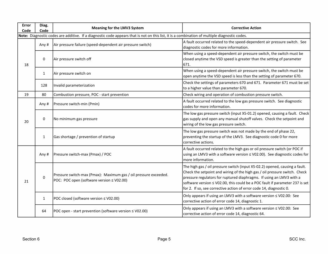
Error
Code
Diag.
CodeMeaning for the LMV3 System Corrective Action
Note: Diagnostic codes are additive. If a diagnostic code appears that is not on this list, it is a combination of multiple diagnostic codes.
Any # Air pressure failure (speed-dependent air pressure switch)A fault occurred related to the speed-dependent air pressure switch. See
diagnostic codes for more information.
0 Air pressure switch off
When using a speed-dependent air pressure switch, the switch must be
closed anytime the VSD speed is greater than the setting of parameter
671.
1 Air pressure switch onWhen using a speed-dependent air pressure switch, the switch must be
open anytime the VSD speed is less than the setting of parameter 670.
128 Invalid parameterizationCheck the settings of parameters 670 and 671. Parameter 671 must be set
to a higher value than parameter 670.
19 80 Combustion pressure, POC - start prevention Check wiring and operation of combustion pressure switch.
Any # Pressure switch-min (Pmin)A fault occurred related to the low gas pressure switch. See diagnostic
codes for more information.
0 No minimum gas pressure
The low gas pressure switch (input X5-01.2) opened, causing a fault. Check
gas supply and open any manual shutoff valves. Check the setpoint and
wiring of the low gas pressure switch.
1 Gas shortage / prevention of startup
The low gas pressure switch was not made by the end of phase 22,
preventing the startup of the LMV3. See diagnostic code 0 for more
corrective actions.
Any # Pressure switch-max (Pmax) / POC
A fault occurred related to the high gas or oil pressure switch (or POC if
using an LMV3 with a software version ≤ V02.00). See diagnostic codes for
more information.
0Pressure switch-max (Pmax): Maximum gas / oil pressure exceeded.
POC: POC open (software version ≤ V02.00)
The high gas / oil pressure switch (input X5-02.2) opened, causing a fault.
Check the setpoint and wiring of the high gas / oil pressure switch. Check
pressure regulators for ruptured diaphragms. If using an LMV3 with a
software version ≤ V02.00, this could be a POC fault if parameter 237 is set
for 2. If so, see corrective action of error code 14, diagnostic 0.
1 POC closed (software version ≤ V02.00)Only appears if using an LMV3 with a software version ≤ V02.00: See
corrective action of error code 14, diagnostic 1.
64 POC open - start prevention (software version ≤ V02.00)Only appears if using an LMV3 with a software version ≤ V02.00: See
corrective action of error code 14, diagnostic 64.
20
21
18
Section 6 Page 5 SCC Inc.
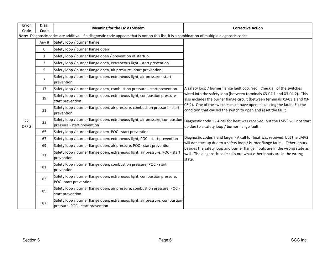
Error
Code
Diag.
CodeMeaning for the LMV3 System Corrective Action
Note: Diagnostic codes are additive. If a diagnostic code appears that is not on this list, it is a combination of multiple diagnostic codes.
Any # Safety loop / burner flange
0 Safety loop / burner flange open
1 Safety loop / burner flange open / prevention of startup
3 Safety loop / burner flange open, extraneous light - start prevention
5 Safety loop / burner flange open, air pressure - start prevention
7Safety loop / burner flange open, extraneous light, air pressure - start
prevention
17 Safety loop / burner flange open, combustion pressure - start prevention
19Safety loop / burner flange open, extraneous light, combustion pressure -
start prevention
21Safety loop / burner flange open, air pressure, combustion pressure - start
prevention
23Safety loop / burner flange open, extraneous light, air pressure, combustion
pressure - start prevention
65 Safety loop / burner flange open, POC - start prevention
67 Safety loop / burner flange open, extraneous light, POC - start prevention
69 Safety loop / burner flange open, air pressure, POC - start prevention
71Safety loop / burner flange open, extraneous light, air pressure, POC - start
prevention
81Safety loop / burner flange open, combustion pressure, POC - start
prevention
83Safety loop / burner flange open, extraneous light, combustion pressure,
POC - start prevention
85Safety loop / burner flange open, air pressure, combustion pressure, POC -
start prevention
87Safety loop / burner flange open, extraneous light, air pressure, combustion
pressure, POC - start prevention
22
OFF S
A safety loop / burner flange fault occurred. Check all of the switches
wired into the safety loop (between terminals X3-04.1 and X3-04.2). This
also includes the burner flange circuit (between terminals X3-03.1 and X3-
03.2). One of the switches must have opened, causing the fault. Fix the
condition that caused the switch to open and reset the fault.
Diagnostic code 1 - A call for heat was received, but the LMV3 will not start
up due to a safety loop / burner flange fault.
Diagnostic codes 3 and larger - A call for heat was received, but the LMV3
will not start up due to a safety loop / burner flange fault. Other inputs
besides the safety loop and burner flange inputs are in the wrong state as
well. The diagnostic code calls out what other inputs are in the wrong
state.
Section 6 Page 6 SCC Inc.
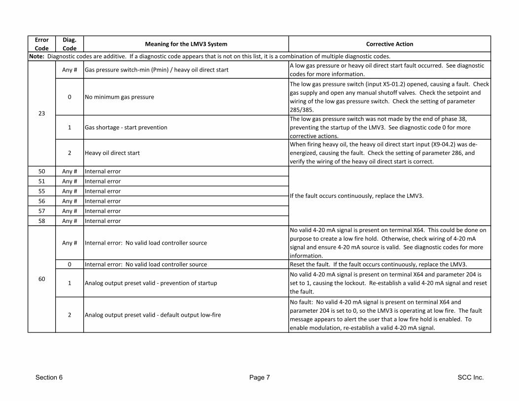
Error
Code
Diag.
CodeMeaning for the LMV3 System Corrective Action
Note: Diagnostic codes are additive. If a diagnostic code appears that is not on this list, it is a combination of multiple diagnostic codes.
Any # Gas pressure switch-min (Pmin) / heavy oil direct startA low gas pressure or heavy oil direct start fault occurred. See diagnostic
codes for more information.
0 No minimum gas pressure
The low gas pressure switch (input X5-01.2) opened, causing a fault. Check
gas supply and open any manual shutoff valves. Check the setpoint and
wiring of the low gas pressure switch. Check the setting of parameter
285/385.
1 Gas shortage - start prevention
The low gas pressure switch was not made by the end of phase 38,
preventing the startup of the LMV3. See diagnostic code 0 for more
corrective actions.
2 Heavy oil direct start
When firing heavy oil, the heavy oil direct start input (X9-04.2) was de-
energized, causing the fault. Check the setting of parameter 286, and
verify the wiring of the heavy oil direct start is correct.
50 Any # Internal error
51 Any # Internal error
55 Any # Internal error
56 Any # Internal error
57 Any # Internal error
58 Any # Internal error
Any # Internal error: No valid load controller source
No valid 4-20 mA signal is present on terminal X64. This could be done on
purpose to create a low fire hold. Otherwise, check wiring of 4-20 mA
signal and ensure 4-20 mA source is valid. See diagnostic codes for more
information.
0 Internal error: No valid load controller source Reset the fault. If the fault occurs continuously, replace the LMV3.
1 Analog output preset valid - prevention of startup
No valid 4-20 mA signal is present on terminal X64 and parameter 204 is
set to 1, causing the lockout. Re-establish a valid 4-20 mA signal and reset
the fault.
2 Analog output preset valid - default output low-fire
No fault: No valid 4-20 mA signal is present on terminal X64 and
parameter 204 is set to 0, so the LMV3 is operating at low fire. The fault
message appears to alert the user that a low fire hold is enabled. To
enable modulation, re-establish a valid 4-20 mA signal.
23
60
If the fault occurs continuously, replace the LMV3.
Section 6 Page 7 SCC Inc.
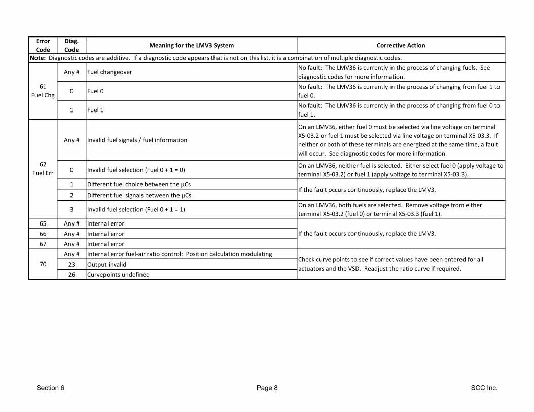
Error
Code
Diag.
CodeMeaning for the LMV3 System Corrective Action
Note: Diagnostic codes are additive. If a diagnostic code appears that is not on this list, it is a combination of multiple diagnostic codes.
Any # Fuel changeoverNo fault: The LMV36 is currently in the process of changing fuels. See
diagnostic codes for more information.
0 Fuel 0No fault: The LMV36 is currently in the process of changing from fuel 1 to
fuel 0.
1 Fuel 1No fault: The LMV36 is currently in the process of changing from fuel 0 to
fuel 1.
Any # Invalid fuel signals / fuel information
On an LMV36, either fuel 0 must be selected via line voltage on terminal
X5-03.2 or fuel 1 must be selected via line voltage on terminal X5-03.3. If
neither or both of these terminals are energized at the same time, a fault
will occur. See diagnostic codes for more information.
0 Invalid fuel selection (Fuel 0 + 1 = 0)On an LMV36, neither fuel is selected. Either select fuel 0 (apply voltage to
terminal X5-03.2) or fuel 1 (apply voltage to terminal X5-03.3).
1 Different fuel choice between the µCs
2 Different fuel signals between the µCs
3 Invalid fuel selection (Fuel 0 + 1 = 1)On an LMV36, both fuels are selected. Remove voltage from either
terminal X5-03.2 (fuel 0) or terminal X5-03.3 (fuel 1).
65 Any # Internal error
66 Any # Internal error
67 Any # Internal error
Any # Internal error fuel-air ratio control: Position calculation modulating
23 Output invalid
26 Curvepoints undefined
61
Fuel Chg
62
Fuel Err
70
If the fault occurs continuously, replace the LMV3.
Check curve points to see if correct values have been entered for all
actuators and the VSD. Readjust the ratio curve if required.
If the fault occurs continuously, replace the LMV3.
Section 6 Page 8 SCC Inc.
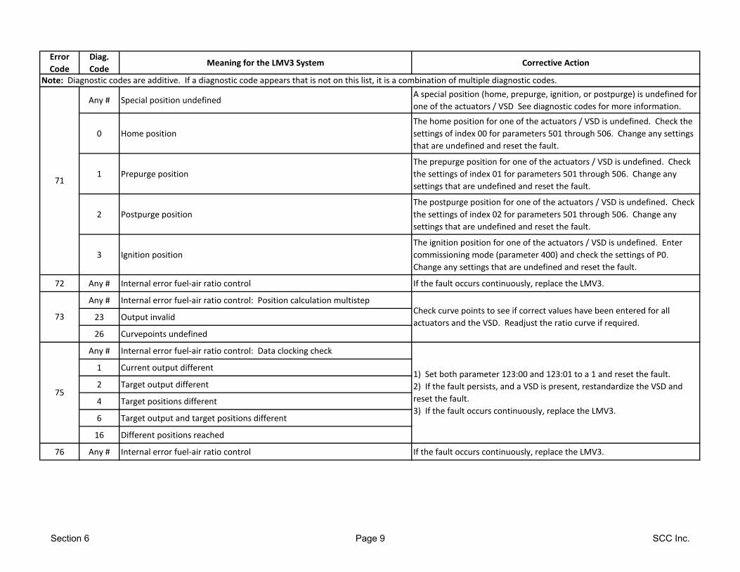
Error
Code
Diag.
CodeMeaning for the LMV3 System Corrective Action
Note: Diagnostic codes are additive. If a diagnostic code appears that is not on this list, it is a combination of multiple diagnostic codes.
Any # Special position undefinedA special position (home, prepurge, ignition, or postpurge) is undefined for
one of the actuators / VSD See diagnostic codes for more information.
0 Home position
The home position for one of the actuators / VSD is undefined. Check the
settings of index 00 for parameters 501 through 506. Change any settings
that are undefined and reset the fault.
1 Prepurge position
The prepurge position for one of the actuators / VSD is undefined. Check
the settings of index 01 for parameters 501 through 506. Change any
settings that are undefined and reset the fault.
2 Postpurge position
The postpurge position for one of the actuators / VSD is undefined. Check
the settings of index 02 for parameters 501 through 506. Change any
settings that are undefined and reset the fault.
3 Ignition position
The ignition position for one of the actuators / VSD is undefined. Enter
commissioning mode (parameter 400) and check the settings of P0.
Change any settings that are undefined and reset the fault.
72 Any # Internal error fuel-air ratio control If the fault occurs continuously, replace the LMV3.
Any # Internal error fuel-air ratio control: Position calculation multistep
23 Output invalid
26 Curvepoints undefined
Any # Internal error fuel-air ratio control: Data clocking check
1 Current output different
2 Target output different
4 Target positions different
6 Target output and target positions different
16 Different positions reached
76 Any # Internal error fuel-air ratio control If the fault occurs continuously, replace the LMV3.
71
73
75
Check curve points to see if correct values have been entered for all
actuators and the VSD. Readjust the ratio curve if required.
1) Set both parameter 123:00 and 123:01 to a 1 and reset the fault.
2) If the fault persists, and a VSD is present, restandardize the VSD and
reset the fault.
3) If the fault occurs continuously, replace the LMV3.
Section 6 Page 9 SCC Inc.
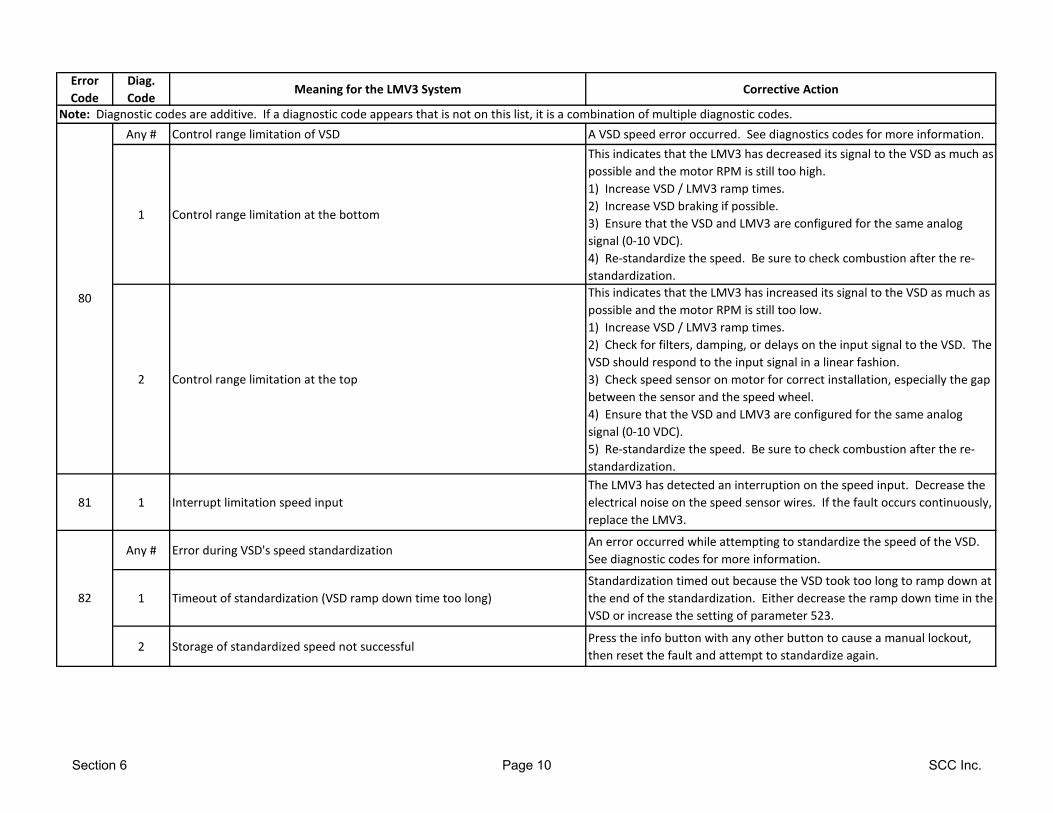
Error
Code
Diag.
CodeMeaning for the LMV3 System Corrective Action
Note: Diagnostic codes are additive. If a diagnostic code appears that is not on this list, it is a combination of multiple diagnostic codes.
Any # Control range limitation of VSD A VSD speed error occurred. See diagnostics codes for more information.
1 Control range limitation at the bottom
This indicates that the LMV3 has decreased its signal to the VSD as much as
possible and the motor RPM is still too high.
1) Increase VSD / LMV3 ramp times.
2) Increase VSD braking if possible.
3) Ensure that the VSD and LMV3 are configured for the same analog
signal (0-10 VDC).
4) Re-standardize the speed. Be sure to check combustion after the re-
standardization.
2 Control range limitation at the top
This indicates that the LMV3 has increased its signal to the VSD as much as
possible and the motor RPM is still too low.
1) Increase VSD / LMV3 ramp times.
2) Check for filters, damping, or delays on the input signal to the VSD. The
VSD should respond to the input signal in a linear fashion.
3) Check speed sensor on motor for correct installation, especially the gap
between the sensor and the speed wheel.
4) Ensure that the VSD and LMV3 are configured for the same analog
signal (0-10 VDC).
5) Re-standardize the speed. Be sure to check combustion after the re-
standardization.
81 1 Interrupt limitation speed input
The LMV3 has detected an interruption on the speed input. Decrease the
electrical noise on the speed sensor wires. If the fault occurs continuously,
replace the LMV3.
Any # Error during VSD's speed standardizationAn error occurred while attempting to standardize the speed of the VSD.
See diagnostic codes for more information.
1 Timeout of standardization (VSD ramp down time too long)
Standardization timed out because the VSD took too long to ramp down at
the end of the standardization. Either decrease the ramp down time in the
VSD or increase the setting of parameter 523.
2 Storage of standardized speed not successfulPress the info button with any other button to cause a manual lockout,
then reset the fault and attempt to standardize again.
80
82
Section 6 Page 10 SCC Inc.
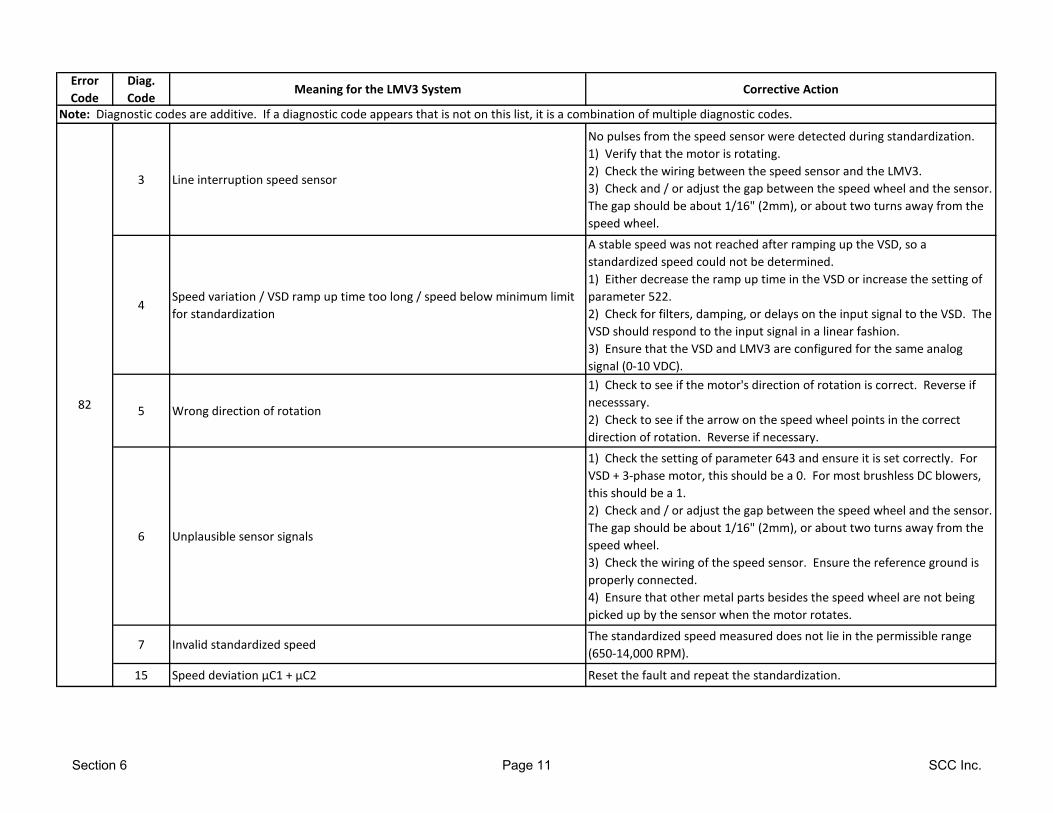
Error
Code
Diag.
CodeMeaning for the LMV3 System Corrective Action
Note: Diagnostic codes are additive. If a diagnostic code appears that is not on this list, it is a combination of multiple diagnostic codes.
3 Line interruption speed sensor
No pulses from the speed sensor were detected during standardization.
1) Verify that the motor is rotating.
2) Check the wiring between the speed sensor and the LMV3.
3) Check and / or adjust the gap between the speed wheel and the sensor.
The gap should be about 1/16" (2mm), or about two turns away from the
speed wheel.
4Speed variation / VSD ramp up time too long / speed below minimum limit
for standardization
A stable speed was not reached after ramping up the VSD, so a
standardized speed could not be determined.
1) Either decrease the ramp up time in the VSD or increase the setting of
parameter 522.
2) Check for filters, damping, or delays on the input signal to the VSD. The
VSD should respond to the input signal in a linear fashion.
3) Ensure that the VSD and LMV3 are configured for the same analog
signal (0-10 VDC).
5 Wrong direction of rotation
1) Check to see if the motor's direction of rotation is correct. Reverse if
necesssary.
2) Check to see if the arrow on the speed wheel points in the correct
direction of rotation. Reverse if necessary.
6 Unplausible sensor signals
1) Check the setting of parameter 643 and ensure it is set correctly. For
VSD + 3-phase motor, this should be a 0. For most brushless DC blowers,
this should be a 1.
2) Check and / or adjust the gap between the speed wheel and the sensor.
The gap should be about 1/16" (2mm), or about two turns away from the
speed wheel.
3) Check the wiring of the speed sensor. Ensure the reference ground is
properly connected.
4) Ensure that other metal parts besides the speed wheel are not being
picked up by the sensor when the motor rotates.
7 Invalid standardized speedThe standardized speed measured does not lie in the permissible range
(650-14,000 RPM).
15 Speed deviation µC1 + µC2 Reset the fault and repeat the standardization.
82
Section 6 Page 11 SCC Inc.
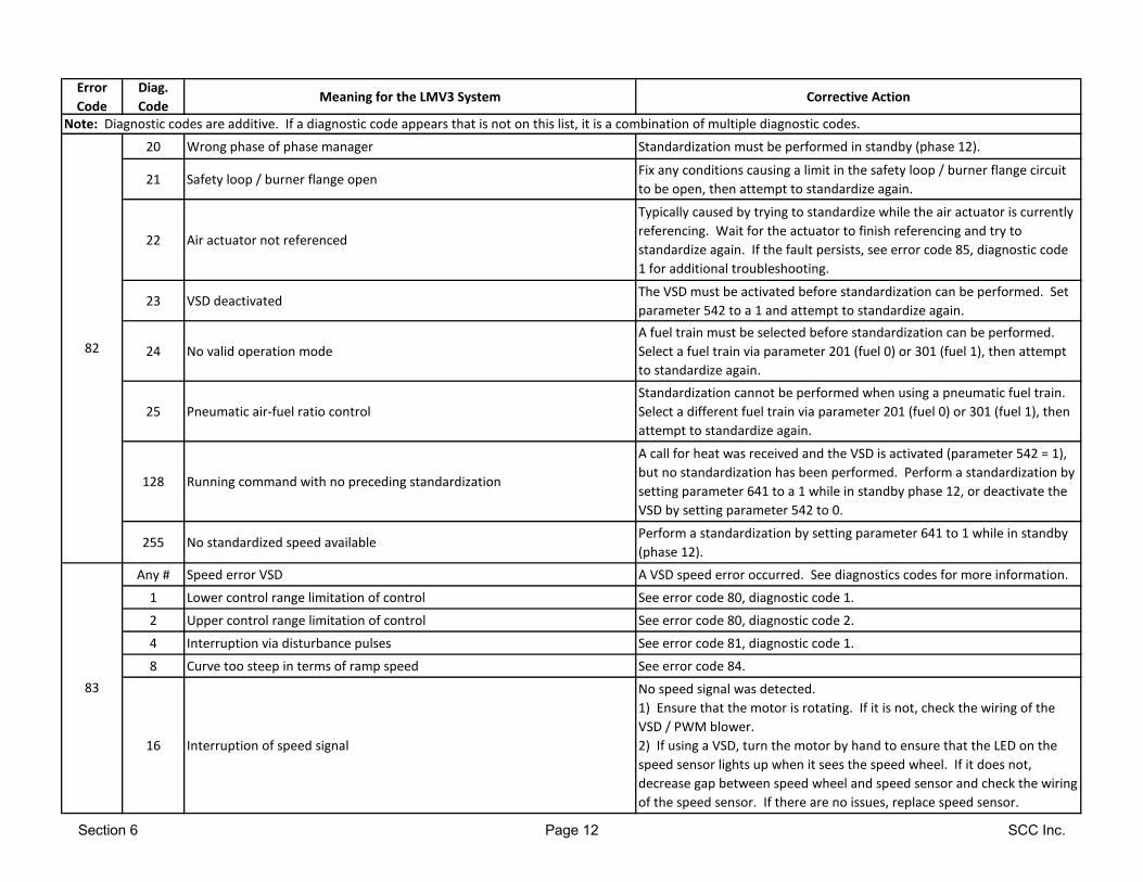
Error
Code
Diag.
CodeMeaning for the LMV3 System Corrective Action
Note: Diagnostic codes are additive. If a diagnostic code appears that is not on this list, it is a combination of multiple diagnostic codes.
20 Wrong phase of phase manager Standardization must be performed in standby (phase 12).
21 Safety loop / burner flange openFix any conditions causing a limit in the safety loop / burner flange circuit
to be open, then attempt to standardize again.
22 Air actuator not referenced
Typically caused by trying to standardize while the air actuator is currently
referencing. Wait for the actuator to finish referencing and try to
standardize again. If the fault persists, see error code 85, diagnostic code
1 for additional troubleshooting.
23 VSD deactivatedThe VSD must be activated before standardization can be performed. Set
parameter 542 to a 1 and attempt to standardize again.
24 No valid operation mode
A fuel train must be selected before standardization can be performed.
Select a fuel train via parameter 201 (fuel 0) or 301 (fuel 1), then attempt
to standardize again.
25 Pneumatic air-fuel ratio control
Standardization cannot be performed when using a pneumatic fuel train.
Select a different fuel train via parameter 201 (fuel 0) or 301 (fuel 1), then
attempt to standardize again.
128 Running command with no preceding standardization
A call for heat was received and the VSD is activated (parameter 542 = 1),
but no standardization has been performed. Perform a standardization by
setting parameter 641 to a 1 while in standby phase 12, or deactivate the
VSD by setting parameter 542 to 0.
255 No standardized speed availablePerform a standardization by setting parameter 641 to 1 while in standby
(phase 12).
Any # Speed error VSD A VSD speed error occurred. See diagnostics codes for more information.
1 Lower control range limitation of control See error code 80, diagnostic code 1.
2 Upper control range limitation of control See error code 80, diagnostic code 2.
4 Interruption via disturbance pulses See error code 81, diagnostic code 1.
8 Curve too steep in terms of ramp speed See error code 84.
16 Interruption of speed signal
No speed signal was detected.
1) Ensure that the motor is rotating. If it is not, check the wiring of the
VSD / PWM blower.
2) If using a VSD, turn the motor by hand to ensure that the LED on the
speed sensor lights up when it sees the speed wheel. If it does not,
decrease gap between speed wheel and speed sensor and check the wiring
of the speed sensor. If there are no issues, replace speed sensor.
82
83
Section 6 Page 12 SCC Inc.
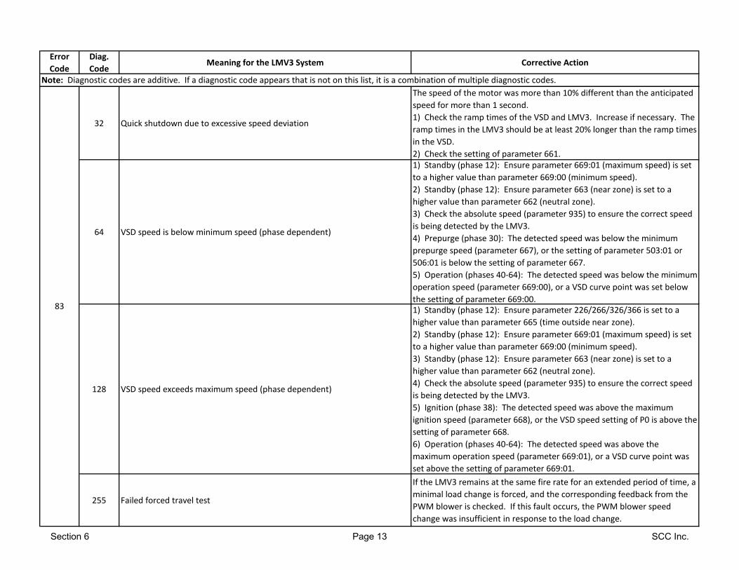
Error
Code
Diag.
CodeMeaning for the LMV3 System Corrective Action
Note: Diagnostic codes are additive. If a diagnostic code appears that is not on this list, it is a combination of multiple diagnostic codes.
32 Quick shutdown due to excessive speed deviation
The speed of the motor was more than 10% different than the anticipated
speed for more than 1 second.
1) Check the ramp times of the VSD and LMV3. Increase if necessary. The
ramp times in the LMV3 should be at least 20% longer than the ramp times
in the VSD.
2) Check the setting of parameter 661.
64 VSD speed is below minimum speed (phase dependent)
1) Standby (phase 12): Ensure parameter 669:01 (maximum speed) is set
to a higher value than parameter 669:00 (minimum speed).
2) Standby (phase 12): Ensure parameter 663 (near zone) is set to a
higher value than parameter 662 (neutral zone).
3) Check the absolute speed (parameter 935) to ensure the correct speed
is being detected by the LMV3.
4) Prepurge (phase 30): The detected speed was below the minimum
prepurge speed (parameter 667), or the setting of parameter 503:01 or
506:01 is below the setting of parameter 667.
5) Operation (phases 40-64): The detected speed was below the minimum
operation speed (parameter 669:00), or a VSD curve point was set below
the setting of parameter 669:00.
128 VSD speed exceeds maximum speed (phase dependent)
1) Standby (phase 12): Ensure parameter 226/266/326/366 is set to a
higher value than parameter 665 (time outside near zone).
2) Standby (phase 12): Ensure parameter 669:01 (maximum speed) is set
to a higher value than parameter 669:00 (minimum speed).
3) Standby (phase 12): Ensure parameter 663 (near zone) is set to a
higher value than parameter 662 (neutral zone).
4) Check the absolute speed (parameter 935) to ensure the correct speed
is being detected by the LMV3.
5) Ignition (phase 38): The detected speed was above the maximum
ignition speed (parameter 668), or the VSD speed setting of P0 is above the
setting of parameter 668.
6) Operation (phases 40-64): The detected speed was above the
maximum operation speed (parameter 669:01), or a VSD curve point was
set above the setting of parameter 669:01.
255 Failed forced travel test
If the LMV3 remains at the same fire rate for an extended period of time, a
minimal load change is forced, and the corresponding feedback from the
PWM blower is checked. If this fault occurs, the PWM blower speed
change was insufficient in response to the load change.
83
Section 6 Page 13 SCC Inc.
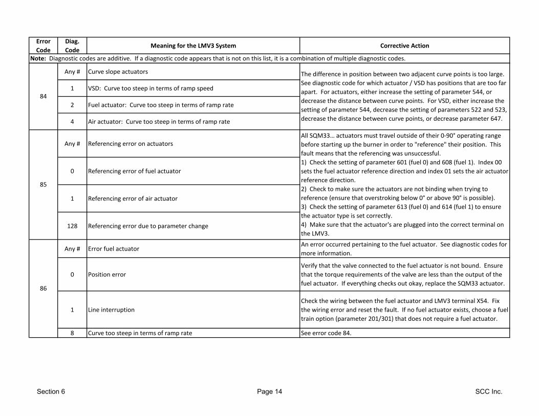
Error
Code
Diag.
CodeMeaning for the LMV3 System Corrective Action
Note: Diagnostic codes are additive. If a diagnostic code appears that is not on this list, it is a combination of multiple diagnostic codes.
Any # Curve slope actuators
1 VSD: Curve too steep in terms of ramp speed
2 Fuel actuator: Curve too steep in terms of ramp rate
4 Air actuator: Curve too steep in terms of ramp rate
Any # Referencing error on actuators
0 Referencing error of fuel actuator
1 Referencing error of air actuator
128 Referencing error due to parameter change
Any # Error fuel actuatorAn error occurred pertaining to the fuel actuator. See diagnostic codes for
more information.
0 Position error
Verify that the valve connected to the fuel actuator is not bound. Ensure
that the torque requirements of the valve are less than the output of the
fuel actuator. If everything checks out okay, replace the SQM33 actuator.
1 Line interruption
Check the wiring between the fuel actuator and LMV3 terminal X54. Fix
the wiring error and reset the fault. If no fuel actuator exists, choose a fuel
train option (parameter 201/301) that does not require a fuel actuator.
8 Curve too steep in terms of ramp rate See error code 84.
84
85
86
All SQM33… actuators must travel outside of their 0-90° operating range
before starting up the burner in order to "reference" their position. This
fault means that the referencing was unsuccessful.
1) Check the setting of parameter 601 (fuel 0) and 608 (fuel 1). Index 00
sets the fuel actuator reference direction and index 01 sets the air actuator
reference direction.
2) Check to make sure the actuators are not binding when trying to
reference (ensure that overstroking below 0° or above 90° is possible).
3) Check the setting of parameter 613 (fuel 0) and 614 (fuel 1) to ensure
the actuator type is set correctly.
4) Make sure that the actuator's are plugged into the correct terminal on
the LMV3.
The difference in position between two adjacent curve points is too large.
See diagnostic code for which actuator / VSD has positions that are too far
apart. For actuators, either increase the setting of parameter 544, or
decrease the distance between curve points. For VSD, either increase the
setting of parameter 544, decrease the setting of parameters 522 and 523,
decrease the distance between curve points, or decrease parameter 647.
Section 6 Page 14 SCC Inc.

Error
Code
Diag.
CodeMeaning for the LMV3 System Corrective Action
Note: Diagnostic codes are additive. If a diagnostic code appears that is not on this list, it is a combination of multiple diagnostic codes.
86 16 Step deviation in comparison with last referencing
The fuel actuator is bound.
1) Check the setting of parameter 613:00 (fuel 0) and 614 (fuel 1) to
ensure the actuator type is set correctly.
2) Check to see if the actuator gets bound somewhere along its working
range. This can be done changing the home position of the actuator in
standby (no alarm).
3) Ensure that the torque of the actuator is sufficient for the application.
Any # Error air actuatorAn error occurred pertaining to the air actuator. See diagnostic codes for
more information.
0 Position error
Verify that the valve / damper connected to the air actuator is not bound.
Ensure that the torque requirements of the valve / damper are less than
the output of the air actuator. If everything checks out okay, replace the
SQM33 actuator.
1 Line interruption
Check the wiring between the air actuator and LMV3 terminal X53. Fix the
wiring error and reset the fault. If no air actuator exists, choose a fuel
train option (parameter 201/301) that does not require an air actuator.
8 Curve too steep in terms of ramp rate See error code 84.
16 Step deviation in comparison with last referencing
The air actuator is bound.
1) Check the setting of parameter 613:01 to ensure the actuator type is
set correctly.
2) Check to see if the actuator gets bound somewhere along its working
range. This can be done changing the home position of the actuator in
standby (no alarm).
3) Ensure that the torque of the actuator is sufficient for the application.
90 Any # Internal error basic unit
91 Any # Internal error basic unit
Any # Error flame signal acquisition
3 Short-circuit of sensor
87
93
If the fault occurs continuously, replace the LMV3.
Check the wiring of the QRB… flame detector and reset the fault. If the
fault occurs continuously, replace the QRB… flame detector.
Section 6 Page 15 SCC Inc.
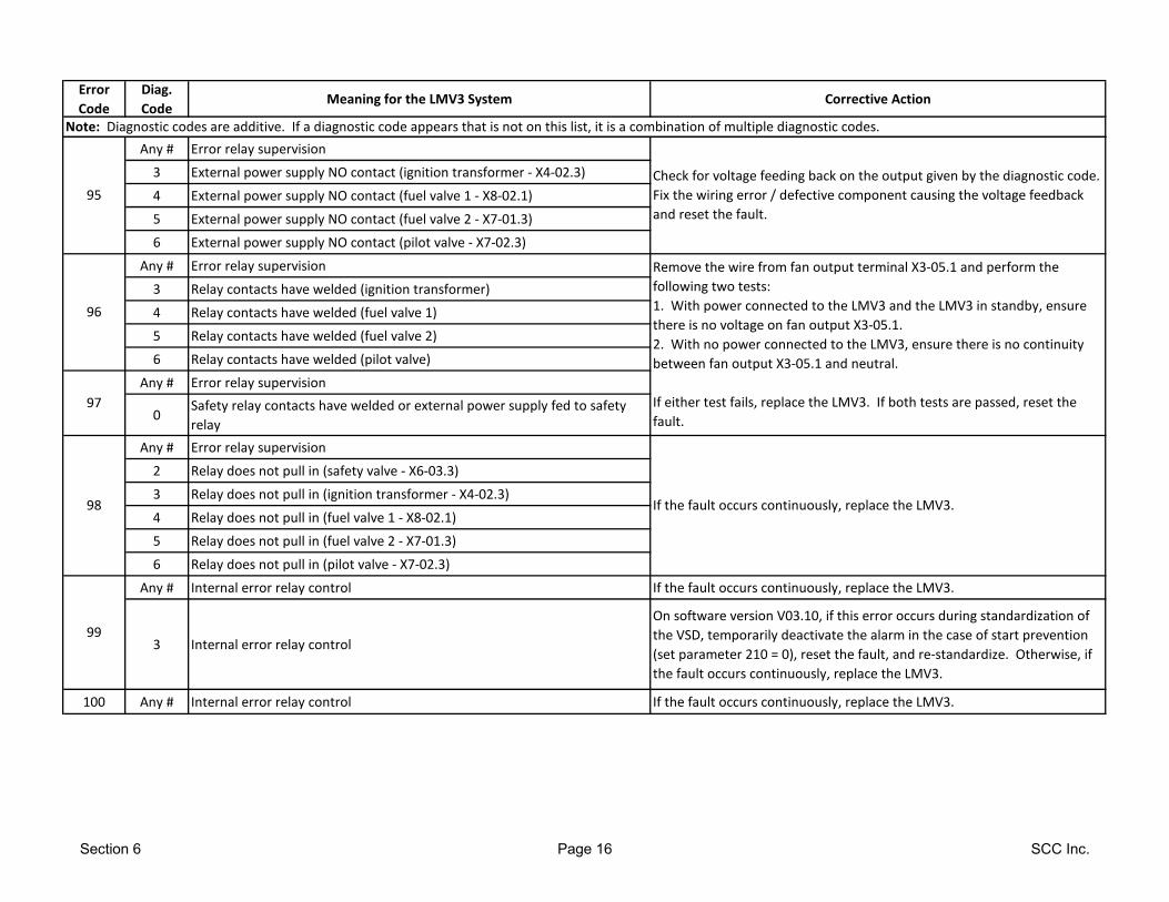
Error
Code
Diag.
CodeMeaning for the LMV3 System Corrective Action
Note: Diagnostic codes are additive. If a diagnostic code appears that is not on this list, it is a combination of multiple diagnostic codes.
Any # Error relay supervision
3 External power supply NO contact (ignition transformer - X4-02.3)
4 External power supply NO contact (fuel valve 1 - X8-02.1)
5 External power supply NO contact (fuel valve 2 - X7-01.3)
6 External power supply NO contact (pilot valve - X7-02.3)
Any # Error relay supervision
3 Relay contacts have welded (ignition transformer)
4 Relay contacts have welded (fuel valve 1)
5 Relay contacts have welded (fuel valve 2)
6 Relay contacts have welded (pilot valve)
Any # Error relay supervision
0Safety relay contacts have welded or external power supply fed to safety
relay
Any # Error relay supervision
2 Relay does not pull in (safety valve - X6-03.3)
3 Relay does not pull in (ignition transformer - X4-02.3)
4 Relay does not pull in (fuel valve 1 - X8-02.1)
5 Relay does not pull in (fuel valve 2 - X7-01.3)
6 Relay does not pull in (pilot valve - X7-02.3)
Any # Internal error relay control If the fault occurs continuously, replace the LMV3.
3 Internal error relay control
On software version V03.10, if this error occurs during standardization of
the VSD, temporarily deactivate the alarm in the case of start prevention
(set parameter 210 = 0), reset the fault, and re-standardize. Otherwise, if
the fault occurs continuously, replace the LMV3.
100 Any # Internal error relay control If the fault occurs continuously, replace the LMV3.
95
96
97
99
98 If the fault occurs continuously, replace the LMV3.
Check for voltage feeding back on the output given by the diagnostic code.
Fix the wiring error / defective component causing the voltage feedback
and reset the fault.
Remove the wire from fan output terminal X3-05.1 and perform the
following two tests:
1. With power connected to the LMV3 and the LMV3 in standby, ensure
there is no voltage on fan output X3-05.1.
2. With no power connected to the LMV3, ensure there is no continuity
between fan output X3-05.1 and neutral.
If either test fails, replace the LMV3. If both tests are passed, reset the
fault.
Section 6 Page 16 SCC Inc.
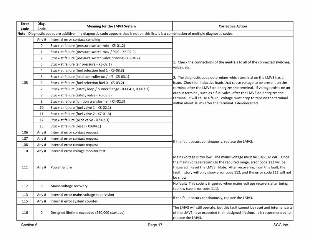
Error
Code
Diag.
CodeMeaning for the LMV3 System Corrective Action
Note: Diagnostic codes are additive. If a diagnostic code appears that is not on this list, it is a combination of multiple diagnostic codes.
Any # Internal error contact sampling
0 Stuck-at failure (pressure switch-min - X5-01.2)
1 Stuck-at failure (pressure switch-max / POC - X5-02.2)
2 Stuck-at failure (pressure switch valve proving - X9-04.2)
3 Stuck-at failure (air pressure - X3-02.1)
4 Stuck-at failure (fuel selection fuel 1 - X5-03.3)
5 Stuck-at failure (load controller on / off - X5-03.1)
6 Stuck-at failure (fuel selection fuel 0 - X5-03.2)
7 Stuck-at failure (safety loop / burner flange - X3-04.1, X3-03.1)
8 Stuck-at failure (safety valve - X6-03.3)
9 Stuck-at failure (ignition transformer - X4-02.3)
10 Stuck-at failure (fuel valve 1 - X8-02.1)
11 Stuck-at failure (fuel valve 2 - X7-01.3)
12 Stuck-at failure (pilot valve - X7-02.3)
13 Stuck-at failure (reset - X8-04.1)
106 Any # Internal error contact request
107 Any # Internal error contact request
108 Any # Internal error contact request
110 Any # Internal error voltage monitor test
111 Any # Power failure
Mains voltage is too low. The mains voltage must be 102-132 VAC. Once
the mains voltage returns to the required range, error code 112 will be
triggered. Reset the LMV3. Note: After recovering from this fault, the
fault history will only show error code 112, and the error code 111 will not
be shown.
112 0 Mains voltage recoveryNo fault: This code is triggered when mains voltage recovers after being
too low (see error code 111).
113 Any # Internal error mains voltage supervision
115 Any # Internal error system counter
116 0 Designed lifetime exceeded (250,000 startups)
The LMV3 will still operate, but this fault cannot be reset and internal parts
of the LMV3 have exceeded their designed lifetime. It is recommended to
replace the LMV3.
105
1. Check the connections of the neutrals to all of the connected switches,
valves, etc.
2. The diagnostic code determines which terminal on the LMV3 has an
issue. Check for inductive loads that cause voltage to be present on the
terminal after the LMV3 de-energizes the terminal. If voltage exists on an
output terminal, such as a fuel valve, after the LMV3 de-energizes the
terminal, it will cause a fault. Voltage must drop to zero on the terminal
within about 10 ms after the terminal is de-energized.
If the fault occurs continuously, replace the LMV3.
If the fault occurs continuously, replace the LMV3.
Section 6 Page 17 SCC Inc.
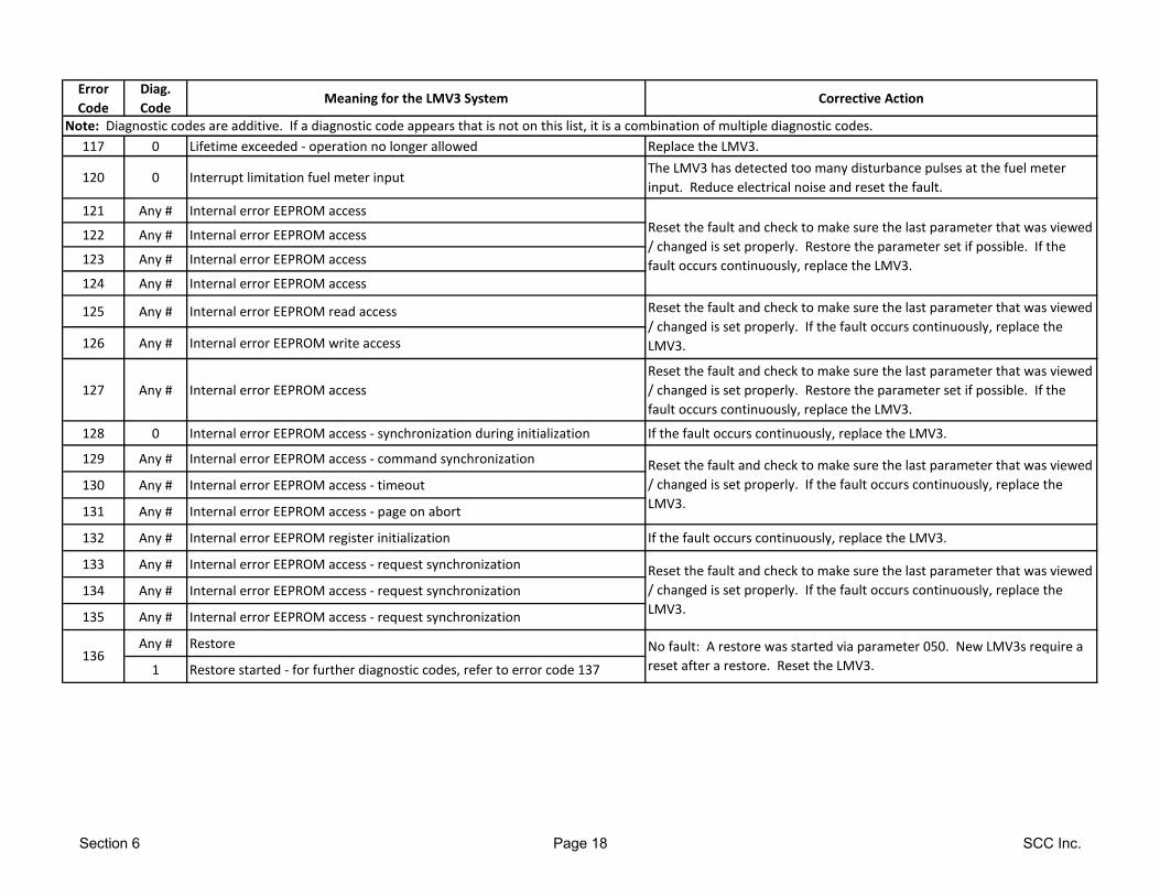
Error
Code
Diag.
CodeMeaning for the LMV3 System Corrective Action
Note: Diagnostic codes are additive. If a diagnostic code appears that is not on this list, it is a combination of multiple diagnostic codes.
117 0 Lifetime exceeded - operation no longer allowed Replace the LMV3.
120 0 Interrupt limitation fuel meter inputThe LMV3 has detected too many disturbance pulses at the fuel meter
input. Reduce electrical noise and reset the fault.
121 Any # Internal error EEPROM access
122 Any # Internal error EEPROM access
123 Any # Internal error EEPROM access
124 Any # Internal error EEPROM access
125 Any # Internal error EEPROM read access
126 Any # Internal error EEPROM write access
127 Any # Internal error EEPROM access
Reset the fault and check to make sure the last parameter that was viewed
/ changed is set properly. Restore the parameter set if possible. If the
fault occurs continuously, replace the LMV3.
128 0 Internal error EEPROM access - synchronization during initialization If the fault occurs continuously, replace the LMV3.
129 Any # Internal error EEPROM access - command synchronization
130 Any # Internal error EEPROM access - timeout
131 Any # Internal error EEPROM access - page on abort
132 Any # Internal error EEPROM register initialization If the fault occurs continuously, replace the LMV3.
133 Any # Internal error EEPROM access - request synchronization
134 Any # Internal error EEPROM access - request synchronization
135 Any # Internal error EEPROM access - request synchronization
Any # Restore
1 Restore started - for further diagnostic codes, refer to error code 137136
Reset the fault and check to make sure the last parameter that was viewed
/ changed is set properly. If the fault occurs continuously, replace the
LMV3.
Reset the fault and check to make sure the last parameter that was viewed
/ changed is set properly. If the fault occurs continuously, replace the
LMV3.
Reset the fault and check to make sure the last parameter that was viewed
/ changed is set properly. If the fault occurs continuously, replace the
LMV3.
No fault: A restore was started via parameter 050. New LMV3s require a
reset after a restore. Reset the LMV3.
Reset the fault and check to make sure the last parameter that was viewed
/ changed is set properly. Restore the parameter set if possible. If the
fault occurs continuously, replace the LMV3.
Section 6 Page 18 SCC Inc.
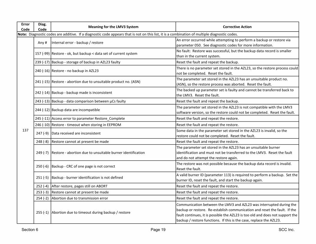
Error
Code
Diag.
CodeMeaning for the LMV3 System Corrective Action
Note: Diagnostic codes are additive. If a diagnostic code appears that is not on this list, it is a combination of multiple diagnostic codes.
Any # Internal error - backup / restoreAn error occurred while attempting to perform a backup or restore via
parameter 050. See diagnostic codes for more information.
157 (-99) Restore - ok, but backup < data set of current systemNo fault: Restore was successful, but the backup data record is smaller
than in the current system.
239 (-17) Backup - storage of backup in AZL23 faulty Reset the fault and repeat the backup.
240 (-16) Restore - no backup in AZL23There is no parameter set stored in the AZL23, so the restore process could
not be completed. Reset the fault.
241 (-15) Restore - abortion due to unsuitable product no. (ASN)The parameter set stored in the AZL23 has an unsuitable product no.
(ASN), so the restore process was aborted. Reset the fault.
242 (-14) Backup - backup made is inconsistentThe backed up parameter set is faulty and cannot be transferred back to
the LMV3. Reset the fault.
243 (-13) Backup - data comparison between µCs faulty Reset the fault and repeat the backup.
244 (-12) Backup data are incompatibleThe parameter set stored in the AZL23 is not compatible with the LMV3
software version, so the restore could not be completed. Reset the fault.
245 (-11) Access error to parameter Restore_Complete Reset the fault and repeat the restore.
246 (-10) Restore - timeout when storing in EEPROM Reset the fault and repeat the restore.
247 (-9) Data received are inconsistentSome data in the parameter set stored in the AZL23 is invalid, so the
restore could not be completed. Reset the fault.
248 (-8) Restore cannot at present be made Reset the fault and repeat the restore.
249 (-7) Restore - abortion due to unsuitable burner identification
The parameter set stored in the AZL23 has an unsuitable burner
identification and must not be transferred to the LMV3. Reset the fault
and do not attempt the restore again.
250 (-6) Backup - CRC of one page is not correctThe restore was not possible because the backup data record is invalid.
Reset the fault.
251 (-5) Backup - burner identification is not definedA valid burner ID (parameter 113) is required to perform a backup. Set the
burner ID, reset the fault, and start the backup again.
252 (-4) After restore, pages still on ABORT Reset the fault and repeat the restore.
253 (-3) Restore cannot at present be made Reset the fault and repeat the restore.
254 (-2) Abortion due to transmission error Reset the fault and repeat the restore.
255 (-1) Abortion due to timeout during backup / restore
Communication between the LMV3 and AZL23 was interrupted during the
backup or restore. Re-establish communication and reset the fault. If the
fault continues, it is possible the AZL23 is too old and does not support the
backup / restore functions. If this is the case, replace the AZL23.
137
Section 6 Page 19 SCC Inc.
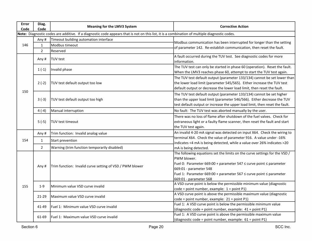
Error
Code
Diag.
CodeMeaning for the LMV3 System Corrective Action
Note: Diagnostic codes are additive. If a diagnostic code appears that is not on this list, it is a combination of multiple diagnostic codes.
Any # Timeout building automation interface
1 Modbus timeout
2 Reserved
Any # TUV testA fault occurred during the TUV test. See diagnostic codes for more
information.
1 (-1) Invalid phaseThe TUV test can only be started in phase 60 (operation). Reset the fault.
When the LMV3 reaches phase 60, attempt to start the TUV test again.
2 (-2) TUV test default output too low
The TUV test default output (parameter 133/134) cannot be set lower than
the lower load limit (parameter 545/565). Either increase the TUV test
default output or decrease the lower load limit, then reset the fault.
3 (-3) TUV test default output too high
The TUV test default output (parameter 133/134) cannot be set higher
than the upper load limit (parameter 546/566). Either decrease the TUV
test default output or increase the upper load limit, then reset the fault.
4 (-4) Manual interruption No fault: The TUV test was aborted manually by the user.
5 (-5) TUV test timeout
There was no loss of flame after shutdown of the fuel valves. Check for
extraneous light or a faulty flame scanner, then reset the fault and start
the TUV test again.
Any # Trim function: Invalid analog value
1 Start prevention
2 Warning (trim function temporarily disabled)
Any # Trim function: Invalid curve setting of VSD / PWM blower
The following equations set the limits on the curve settings for the VSD /
PWM blower.
Fuel 0: Parameter 669:00 + parameter 547 ≤ curve point ≤ parameter
669:01 - parameter 548
Fuel 1: Parameter 669:00 + parameter 567 ≤ curve point ≤ parameter
669:01 - parameter 568
1-9 Minimum value VSD curve invalidA VSD curve point is below the permissible minimum value (diagnostic
code = point number, example: 1 = point P1)
21-29 Maximum value VSD curve invalidA VSD curve point is above the permissible maximum value (diagnostic
code = point number, example: 21 = point P1)
41-49 Fuel 1: Minimum value VSD curve invalidFuel 1: A VSD curve point is below the permissible minimum value
(diagnostic code = point number, example: 41 = point P1)
61-69 Fuel 1: Maximum value VSD curve invalidFuel 1: A VSD curve point is above the permissible maximum value
(diagnostic code = point number, example: 61 = point P1)
155
146
150
154
Modbus communication has been interrupted for longer than the setting
of parameter 142. Re-establish communication, then reset the fault.
An invalid 4-20 mA signal was detected on input X64. Check the wiring to
terminal X64. Check the value of parameter 916. A value under -16%
indicates <4 mA is being detected, while a value over 26% indicates >20
mA is being detected.
Section 6 Page 20 SCC Inc.

Error
Code
Diag.
CodeMeaning for the LMV3 System Corrective Action
Note: Diagnostic codes are additive. If a diagnostic code appears that is not on this list, it is a combination of multiple diagnostic codes.
Any # Trim function: Maximum time for trim limit exceededA trim limit was met for the maximum allowable time. See diagnostic
codes for more information.
0 Lower limit trim function
The VSD trim signal was lower than allowed by the minimum trim limit
(parameter 547) for a time period longer than the maximum time allowed
(parameter 551).
1 Upper limit trim function
The VSD trim signal was higher than allowed by the maximum trim limit
(parameter 548) for a time period longer than the maximum allowed
(parameter 551).
10 Fuel 1: Lower limit trim function
The VSD trim signal was lower than allowed by the minimum trim limit
(parameter 567) for a time period longer than the maximum time allowed
(parameter 571).
11 Fuel 1: Upper limit trim function
The VSD trim signal was higher than allowed by the maximum trim limit
(parameter 568) for a time period longer than the maximum allowed
(parameter 571).
Any # Trim function: Failed the analog input testA fault occurred during the analog input test. See diagnostic codes for
more information.
0 Analog value standby
If the analog input test is enabled, the LMV3 looks for 12mA to be present
on terminal X64 during standby. Check parameter 916 to ensure that the
input signal lies in the permissible range of -1%...+1%. Setting parameter
530 to a value other than 2 or 4 disables the analog input test.
1 Analog value prevention
If the analog input test is enabled, the LMV3 looks for 4mA to be present
on terminal X64 during prepurge. Check parameter 916 to ensure that the
input signal lies in the permissible range of -16%...-14%. Setting parameter
530 to a value other than 2 or 4 disables the analog input test.
165 Any # Internal error
166 0 Internal error watchdog reset
156
157
If the fault occurs continuously, replace the LMV3.
Section 6 Page 21 SCC Inc.
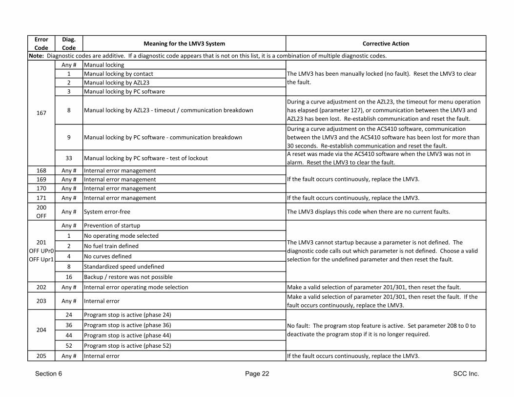
Error
Code
Diag.
CodeMeaning for the LMV3 System Corrective Action
Note: Diagnostic codes are additive. If a diagnostic code appears that is not on this list, it is a combination of multiple diagnostic codes.
Any # Manual locking
1 Manual locking by contact
2 Manual locking by AZL23
3 Manual locking by PC software
8 Manual locking by AZL23 - timeout / communication breakdown
During a curve adjustment on the AZL23, the timeout for menu operation
has elapsed (parameter 127), or communication between the LMV3 and
AZL23 has been lost. Re-establish communication and reset the fault.
9 Manual locking by PC software - communication breakdown
During a curve adjustment on the ACS410 software, communication
between the LMV3 and the ACS410 software has been lost for more than
30 seconds. Re-establish communication and reset the fault.
33 Manual locking by PC software - test of lockoutA reset was made via the ACS410 software when the LMV3 was not in
alarm. Reset the LMV3 to clear the fault.
168 Any # Internal error management
169 Any # Internal error management
170 Any # Internal error management
171 Any # Internal error management If the fault occurs continuously, replace the LMV3.
200
OFFAny # System error-free The LMV3 displays this code when there are no current faults.
Any # Prevention of startup
1 No operating mode selected
2 No fuel train defined
4 No curves defined
8 Standardized speed undefined
16 Backup / restore was not possible
202 Any # Internal error operating mode selection Make a valid selection of parameter 201/301, then reset the fault.
203 Any # Internal errorMake a valid selection of parameter 201/301, then reset the fault. If the
fault occurs continuously, replace the LMV3.
24 Program stop is active (phase 24)
36 Program stop is active (phase 36)
44 Program stop is active (phase 44)
52 Program stop is active (phase 52)
205 Any # Internal error If the fault occurs continuously, replace the LMV3.
If the fault occurs continuously, replace the LMV3.
167
No fault: The program stop feature is active. Set parameter 208 to 0 to
deactivate the program stop if it is no longer required.
The LMV3 cannot startup because a parameter is not defined. The
diagnostic code calls out which parameter is not defined. Choose a valid
selection for the undefined parameter and then reset the fault.
The LMV3 has been manually locked (no fault). Reset the LMV3 to clear
the fault.
201
OFF UPr0
OFF Upr1
204
Section 6 Page 22 SCC Inc.
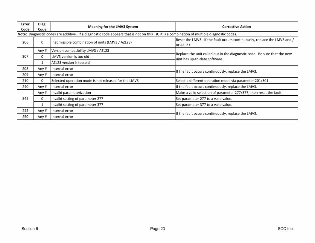
Error
Code
Diag.
CodeMeaning for the LMV3 System Corrective Action
Note: Diagnostic codes are additive. If a diagnostic code appears that is not on this list, it is a combination of multiple diagnostic codes.
206 0 Inadmissible combination of units (LMV3 / AZL23)Reset the LMV3. If the fault occurs continuously, replace the LMV3 and /
or AZL23.
Any # Version compatibility LMV3 / AZL23
0 LMV3 version is too old
1 AZL23 version is too old
208 Any # Internal error
209 Any # Internal error
210 0 Selected operation mode is not released for the LMV3 Select a different operation mode via parameter 201/301.
240 Any # Internal error If the fault occurs continuously, replace the LMV3.
Any # Invalid parameterization Make a valid selection of parameter 277/377, then reset the fault.
0 Invalid setting of parameter 277 Set parameter 277 to a valid value.
1 Invalid setting of parameter 377 Set parameter 377 to a valid value.
245 Any # Internal error
250 Any # Internal error
242
If the fault occurs continuously, replace the LMV3.
If the fault occurs continuously, replace the LMV3.
Replace the unit called out in the diagnostic code. Be sure that the new
unit has up-to-date software.207
Section 6 Page 23 SCC Inc.

LMV Series Technical Instructions
Document No. LV3-1000
SCC Inc. Page 24 Section 6
Intentionally Left Blank
Section 1 Overview
Section 2 Wiring
Section 3 Parameters
Section 4 Commissioning
Section 5 VSD
Section 6 Troubleshooting
Section 7 Modbus
Section 8 ACS410
Appendix A Application Guide

Section 1 Overview
Section 2 Wiring
Section 3 Parameters
Section 4 Commissioning
Section 5 VSD
Section 6 Troubleshooting
Section 7 Modbus
Section 8 ACS410
Appendix A Application Guide
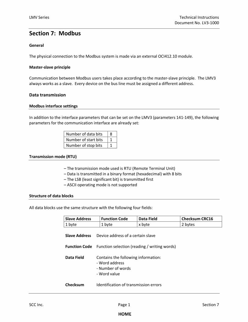
LMV Series Technical Instructions
Document No. LV3-1000
SCC Inc. Page 1 Section 7
Section 7: Modbus
General
The physical connection to the Modbus system is made via an external OCI412.10 module.
Master-slave principle
Communication between Modbus users takes place according to the master-slave principle. The LMV3
always works as a slave. Every device on the bus line must be assigned a different address.
Data transmission
Modbus interface settings
In addition to the interface parameters that can be set on the LMV3 (parameters 141-149), the following
parameters for the communication interface are already set:
Number of data bits 8
Number of start bits 1
Number of stop bits 1
Transmission mode (RTU)
– The transmission mode used is RTU (Remote Terminal Unit)
– Data is transmitted in a binary format (hexadecimal) with 8 bits
– The LSB (least significant bit) is transmitted first
– ASCII operating mode is not supported
Structure of data blocks
All data blocks use the same structure with the following four fields:
Slave Address Function Code Data Field Checksum CRC16
1 byte 1 byte x byte 2 bytes
Slave Address Device address of a certain slave
Function Code Function selection (reading / writing words)
Data Field Contains the following information:
- Word address
- Number of words
- Word value
Checksum Identification of transmission errors
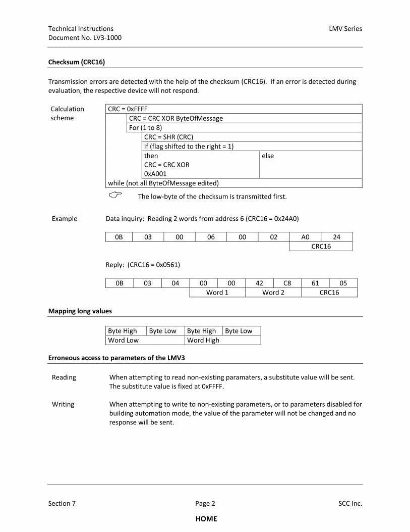
Technical Instructions LMV Series
Document No. LV3-1000
Section 7 Page 2 SCC Inc.
Checksum (CRC16)
Transmission errors are detected with the help of the checksum (CRC16). If an error is detected during
evaluation, the respective device will not respond.
Calculation
scheme
CRC = 0xFFFF
CRC = CRC XOR ByteOfMessage
For (1 to 8)
CRC = SHR (CRC)
if (flag shifted to the right = 1)
then
CRC = CRC XOR
0xA001
else
while (not all ByteOfMessage edited)
� The low-byte of the checksum is transmitted first.
Example Data inquiry: Reading 2 words from address 6 (CRC16 = 0x24A0)
0B 03 00 06 00 02 A0 24
CRC16
Reply: (CRC16 = 0x0561)
0B 03 04 00 00 42 C8 61 05
Word 1 Word 2 CRC16
Mapping long values
Byte High Byte Low Byte High Byte Low
Word Low Word High
Erroneous access to parameters of the LMV3
Reading
When attempting to read non-existing paramaters, a substitute value will be sent.
The substitute value is fixed at 0xFFFF.
Writing When attempting to write to non-existing parameters, or to parameters disabled for
building automation mode, the value of the parameter will not be changed and no
response will be sent.
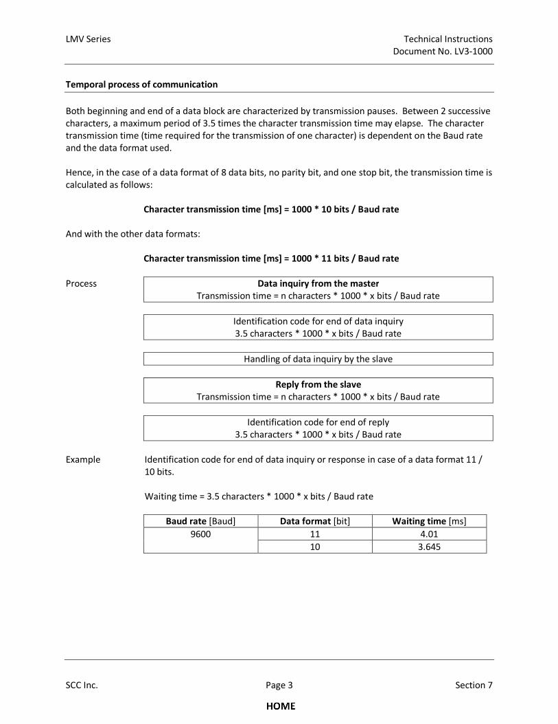
LMV Series Technical Instructions
Document No. LV3-1000
SCC Inc. Page 3 Section 7
Temporal process of communication
Both beginning and end of a data block are characterized by transmission pauses. Between 2 successive
characters, a maximum period of 3.5 times the character transmission time may elapse. The character
transmission time (time required for the transmission of one character) is dependent on the Baud rate
and the data format used.
Hence, in the case of a data format of 8 data bits, no parity bit, and one stop bit, the transmission time is
calculated as follows:
Character transmission time [ms] = 1000 * 10 bits / Baud rate
And with the other data formats:
Character transmission time [ms] = 1000 * 11 bits / Baud rate
Process Data inquiry from the master
Transmission time = n characters * 1000 * x bits / Baud rate
Identification code for end of data inquiry
3.5 characters * 1000 * x bits / Baud rate
Handling of data inquiry by the slave
Reply from the slave
Transmission time = n characters * 1000 * x bits / Baud rate
Identification code for end of reply
3.5 characters * 1000 * x bits / Baud rate
Example Identification code for end of data inquiry or response in case of a data format 11 /
10 bits.
Waiting time = 3.5 characters * 1000 * x bits / Baud rate
Baud rate [Baud] Data format [bit] Waiting time [ms]
9600 11 4.01
10 3.645
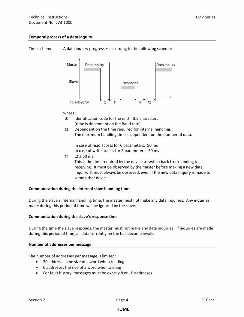
Technical Instructions LMV Series
Document No. LV3-1000
Section 7 Page 4 SCC Inc.
Temporal process of a data inquiry
Time scheme A data inquiry progresses according to the following scheme:
where:
t0 Identification code for the end = 3.5 characters
(time is dependent on the Baud rate)
t1 Dependent on the time required for internal handling.
The maximum handling time is dependent on the number of data.
In case of read access for 6 parameters: 50 ms
In case of write access for 2 parameters: 50 ms
t2 t2 ≥ 50 ms
This is the time required by the device to switch back from sending to
receiving. It must be observed by the master before making a new data
inquiry. It must always be observed, even if the new data inquiry is made to
some other device.
Communication during the internal slave handling time
During the slave’s internal handling time, the master must not make any data inquiries. Any inquiries
made during this period of time will be ignored by the slave.
Communication during the slave’s response time
During the time the slave responds, the master must not make any data inquiries. If inquiries are made
during this period of time, all data currently on the bus become invalid.
Number of addresses per message
The number of addresses per message is limited:
• 20 addresses the size of a word when reading
• 6 addresses the size of a word when writing
• For fault history, messages must be exactly 8 or 16 addresses
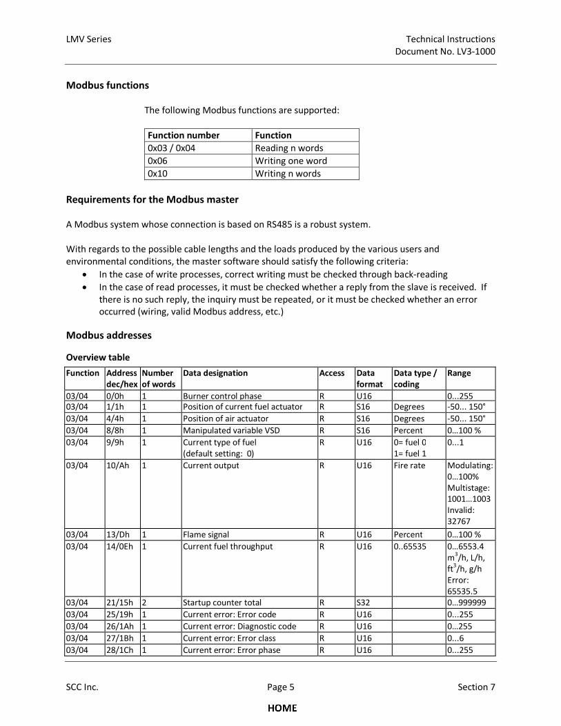
LMV Series Technical Instructions
Document No. LV3-1000
SCC Inc. Page 5 Section 7
Modbus functions
The following Modbus functions are supported:
Function number Function
0x03 / 0x04 Reading n words
0x06 Writing one word
0x10 Writing n words
Requirements for the Modbus master
A Modbus system whose connection is based on RS485 is a robust system.
With regards to the possible cable lengths and the loads produced by the various users and
environmental conditions, the master software should satisfy the following criteria:
• In the case of write processes, correct writing must be checked through back-reading
• In the case of read processes, it must be checked whether a reply from the slave is received. If
there is no such reply, the inquiry must be repeated, or it must be checked whether an error
occurred (wiring, valid Modbus address, etc.)
Modbus addresses Overview table
Function Address
dec/hex
Number
of words
Data designation Access Data
format
Data type /
coding
Range
03/04 0/0h 1 Burner control phase R U16 0...255
03/04 1/1h 1 Position of current fuel actuator R S16 Degrees -50... 150°
03/04 4/4h 1 Position of air actuator R S16 Degrees -50... 150°
03/04 8/8h 1 Manipulated variable VSD R S16 Percent 0…100 %
03/04 9/9h 1 Current type of fuel
(default setting: 0)
R U16 0= fuel 0
1= fuel 1
0...1
03/04 10/Ah 1 Current output R U16 Fire rate Modulating:
0…100%
Multistage:
1001…1003
Invalid:
32767
03/04 13/Dh 1 Flame signal R U16 Percent 0…100 %
03/04 14/0Eh 1 Current fuel throughput R U16 0..65535 0…6553.4
m3/h, L/h,
ft3/h, g/h
Error:
65535.5
03/04 21/15h 2 Startup counter total R S32 0…999999
03/04 25/19h 1 Current error: Error code R U16 0...255
03/04 26/1Ah 1 Current error: Diagnostic code R U16 0…255
03/04 27/1Bh 1 Current error: Error class R U16 0...6
03/04 28/1Ch 1 Current error: Error phase R U16 0...255
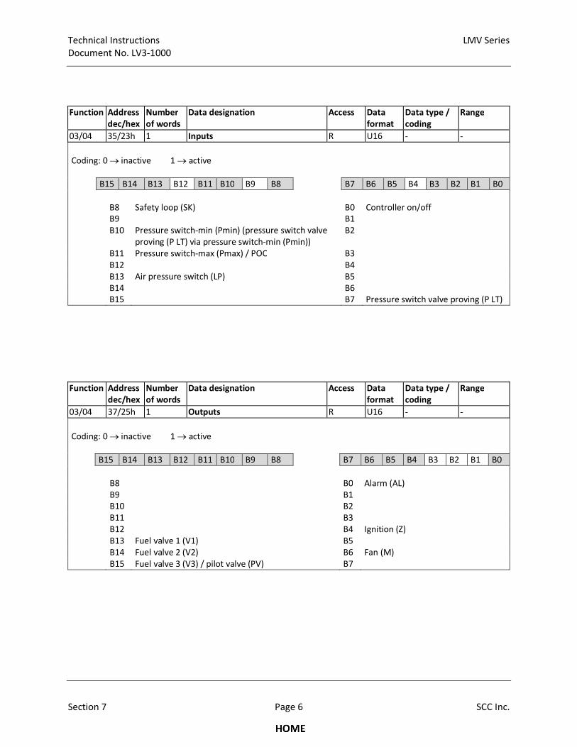
Technical Instructions LMV Series
Document No. LV3-1000
Section 7 Page 6 SCC Inc.
Function Address
dec/hex
Number
of words
Data designation Access Data
format
Data type /
coding
Range
03/04 35/23h 1 Inputs R U16 - -
Coding: 0 → inactive 1 → active
B15 B14 B13 B12 B11 B10 B9 B8 B7 B6 B5 B4 B3 B2 B1 B0
B8
B9
B10
Safety loop (SK)
Pressure switch-min (Pmin) (pressure switch valve
proving (P LT) via pressure switch-min (Pmin))
B0
B1
B2
Controller on/off
B11 Pressure switch-max (Pmax) / POC B3
B12 B4
B13 Air pressure switch (LP) B5
B14 B6
B15 B7 Pressure switch valve proving (P LT)
Function Address
dec/hex
Number
of words
Data designation Access Data
format
Data type /
coding
Range
03/04 37/25h 1 Outputs R U16 - -
Coding: 0 → inactive 1 → active
B15 B14 B13 B12 B11 B10 B9 B8 B7 B6 B5 B4 B3 B2 B1 B0
B8 B0 Alarm (AL)
B9 B1
B10 B2
B11 B3
B12 B4 Ignition (Z)
B13 Fuel valve 1 (V1) B5
B14 Fuel valve 2 (V2) B6 Fan (M)
B15 Fuel valve 3 (V3) / pilot valve (PV) B7
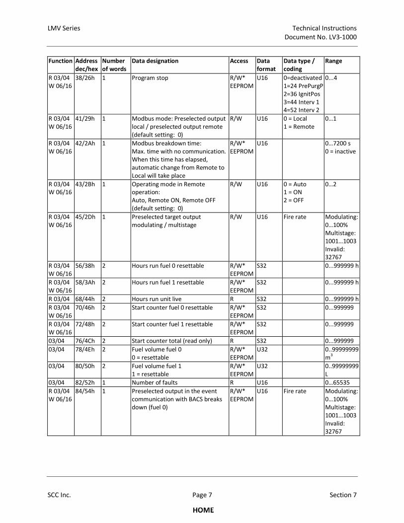
LMV Series Technical Instructions
Document No. LV3-1000
SCC Inc. Page 7 Section 7
Function Address
dec/hex
Number
of words
Data designation Access Data
format
Data type /
coding
Range
R 03/04
W 06/16
38/26h 1 Program stop R/W*
EEPROM
U16 0=deactivated
1=24 PrePurgP
2=36 IgnitPos
3=44 Interv 1
4=52 Interv 2
0...4
R 03/04
W 06/16
41/29h 1 Modbus mode: Preselected output
local / preselected output remote
(default setting: 0)
R/W U16 0 = Local
1 = Remote
0…1
R 03/04
W 06/16
42/2Ah 1 Modbus breakdown time:
Max. time with no communication.
When this time has elapsed,
automatic change from Remote to
Local will take place
R/W*
EEPROM
U16 0…7200 s
0 = inactive
R 03/04
W 06/16
43/2Bh 1 Operating mode in Remote
operation:
Auto, Remote ON, Remote OFF
(default setting: 0)
R/W U16 0 = Auto
1 = ON
2 = OFF
0…2
R 03/04
W 06/16
45/2Dh 1 Preselected target output
modulating / multistage
R/W U16 Fire rate Modulating:
0…100%
Multistage:
1001…1003
Invalid:
32767
R 03/04
W 06/16
56/38h 2 Hours run fuel 0 resettable R/W*
EEPROM
S32 0...999999 h
R 03/04
W 06/16
58/3Ah 2 Hours run fuel 1 resettable R/W*
EEPROM
S32 0...999999 h
R 03/04 68/44h 2 Hours run unit live R S32 0...999999 h
R 03/04
W 06/16
70/46h 2 Start counter fuel 0 resettable R/W*
EEPROM
S32 0...999999
R 03/04
W 06/16
72/48h 2 Start counter fuel 1 resettable R/W*
EEPROM
S32 0...999999
03/04 76/4Ch 2 Start counter total (read only) R S32 0...999999
03/04 78/4Eh 2 Fuel volume fuel 0
0 = resettable
R/W*
EEPROM
U32 0..99999999
m3
03/04 80/50h 2 Fuel volume fuel 1
1 = resettable
R/W*
EEPROM
U32 0..99999999
L
03/04 82/52h 1 Number of faults R U16 0…65535
R 03/04
W 06/16
84/54h 1 Preselected output in the event
communication with BACS breaks
down (fuel 0)
R/W*
EEPROM
U16 Fire rate Modulating:
0…100%
Multistage:
1001…1003
Invalid:
32767

Technical Instructions LMV Series
Document No. LV3-1000
Section 7 Page 8 SCC Inc.
Function Address
dec/hex
Number
of words
Data designation Access Data
format
Data type /
coding
Range
R 03/04
W 06/16
85/55h 1 Preselected output in the event
communication with BACS breaks
down (fuel 1)
R/W*
EEPROM
U16 Fire rate Modulating:
0…100%
Multistage:
1001…1003
Invalid:
32767
03/04 98/62h 8 Burner control type reference
(ASN)
R U8[16] String
03/04 106/6Ah 1 Burner control parameter set code R U16
03/04 107/6Bh 1 Burner control parameter set
version
R U16
03/04 108/6Ch 3 Burner control identification date R U16[3] Data
03/04 111/6Fh 1 Burner control identification
number
R U16
03/04 113/71h 1 Software version burner control R U16 Hexadecimal
03/04 115/73h 8 Burner identification R U8[16] String
03/04 123/7Bh 1 Minimum output fuel 0 R U16 Fire rate limit 20…100%
1001…1003
Invalid:
32767
03/04 124/7Ch 1 Maximum output fuel 0 R U16 Fire rate limit 20…100%
1001…1003
Invalid:
32767
03/04 125/7Dh 1 Minimum output fuel 1 R U16 Fire rate limit 20…100%
1001…1003
Invalid:
32767
03/04 126/7Eh 1 Maximum output fuel 1 R U16 Fire rate limit 20…100%
1001…1003
Invalid:
32767
03/04 127/7Fh 1 Operation mode of burner fuel 0 R U16 1…27
03/04 128/80h 1 Operation mode of burner fuel 1 R U16 1…27
03/04 129/81h 2 Switching cycles Revert to pilot R S32 0…9999999
03/04 140/8Ch 1 Operation mode of burner fuel 0 R U16 1…29
03/04 141/8Dh 1 Operation mode of burner fuel 1 R U16 1…29
03/04 142/8Eh 2 Switching cycles Revert to pilot R S32 0…9999999
03/04 144/90 1 Lower range limit trim function fuel
0
R S16 Percent 0…-15%
03/04 145/91 1 Upper range limit trim function fuel
0
R S16 Percent 0…25%
03/04 146/92 1 Lower range limit trim function fuel
1
R S16 Percent 0…-15%
03/04 147/93 1 Upper range limit trim function fuel
1
R S16 Percent 0…25%
03/04 148/94 1 Input value analog input trim
function
R S16 Percent -15…+25%
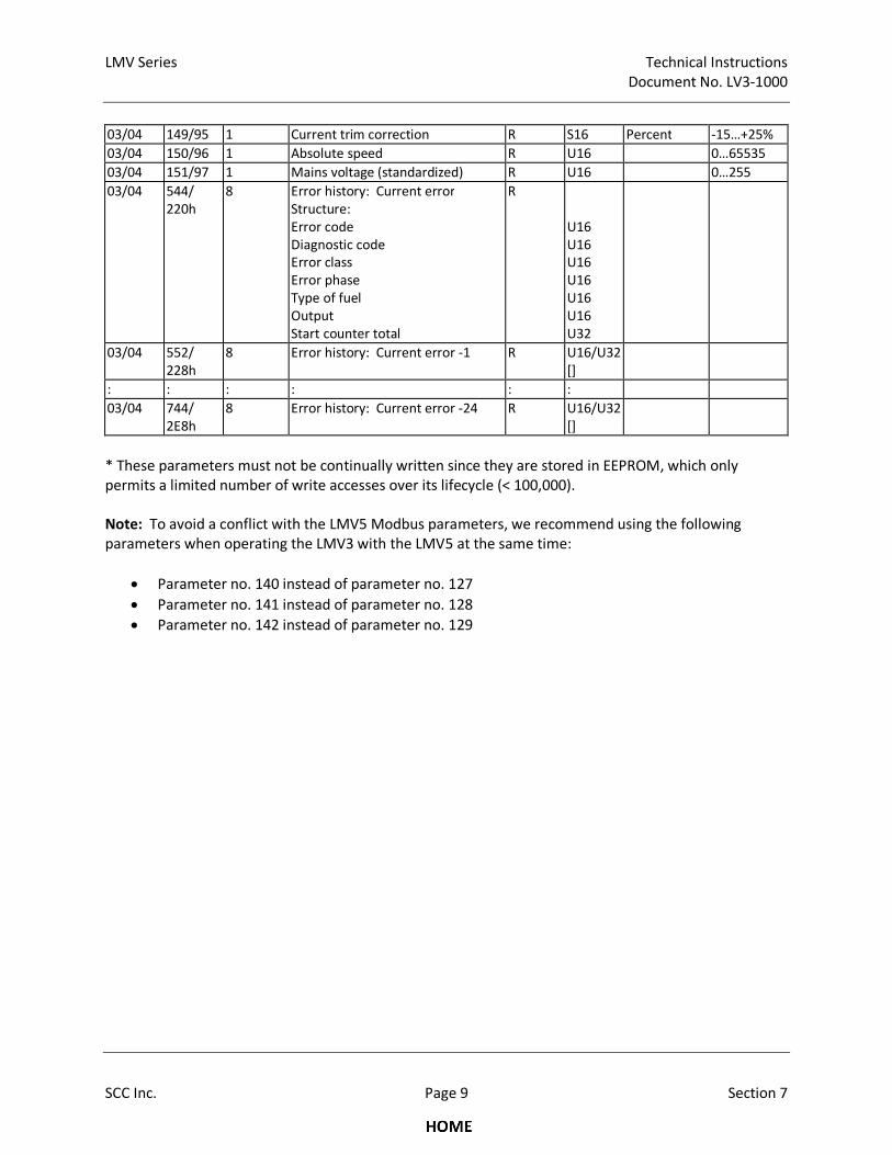
LMV Series Technical Instructions
Document No. LV3-1000
SCC Inc. Page 9 Section 7
03/04 149/95 1 Current trim correction R S16 Percent -15…+25%
03/04 150/96 1 Absolute speed R U16 0…65535
03/04 151/97 1 Mains voltage (standardized) R U16 0…255
03/04 544/
220h
8 Error history: Current error
Structure:
Error code
Diagnostic code
Error class
Error phase
Type of fuel
Output
Start counter total
R
U16
U16
U16
U16
U16
U16
U32
03/04 552/
228h
8 Error history: Current error -1 R U16/U32
[]
: : : : : :
03/04 744/
2E8h
8 Error history: Current error -24 R U16/U32
[]
* These parameters must not be continually written since they are stored in EEPROM, which only
permits a limited number of write accesses over its lifecycle (< 100,000).
Note: To avoid a conflict with the LMV5 Modbus parameters, we recommend using the following
parameters when operating the LMV3 with the LMV5 at the same time:
• Parameter no. 140 instead of parameter no. 127
• Parameter no. 141 instead of parameter no. 128
• Parameter no. 142 instead of parameter no. 129
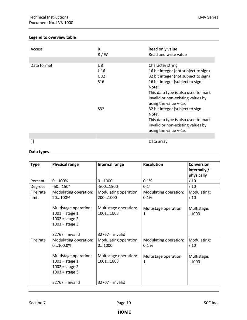
Technical Instructions LMV Series
Document No. LV3-1000
Section 7 Page 10 SCC Inc.
Legend to overview table
Access R Read only value
R / W Read and write value
Data format U8 Character string
U16 16 bit integer (not subject to sign)
U32 32 bit integer (not subject to sign)
S16 16 bit integer (subject to sign)
Note:
This data type is also used to mark
invalid or non-existing values by
using the value «-1».
S32 32 bit integer (subject to sign)
Note:
This data type is also used to mark
invalid or non-existing values by
using the value «-1».
[ ] Data array
Data types
Type Physical range Internal range Resolution Conversion
internally /
physically
Percent 0...100% 0...1000 0.1% / 10
Degrees -50...150° -500…1500 0.1° / 10
Fire rate
limit
Modulating operation:
20...100%
Multistage operation:
1001 = stage 1
1002 = stage 2
1003 = stage 3
32767 = invalid
Modulating operation:
200...1000
Multistage operation:
1001…1003
32767 = invalid
Modulating operation:
0.1%
Multistage operation:
1
Modulating:
/ 10
Multistage:
- 1000
Fire rate Modulating operation:
0...100.0%
Multistage operation:
1001 = stage 1
1002 = stage 2
1003 = stage 3
32767 = invalid
Modulating operation:
0...1000
Multistage operation:
1001…1003
32767 = invalid
Modulating operation:
0.1 %
Multistage operation:
1
Modulating:
/ 10
Multistage:
- 1000
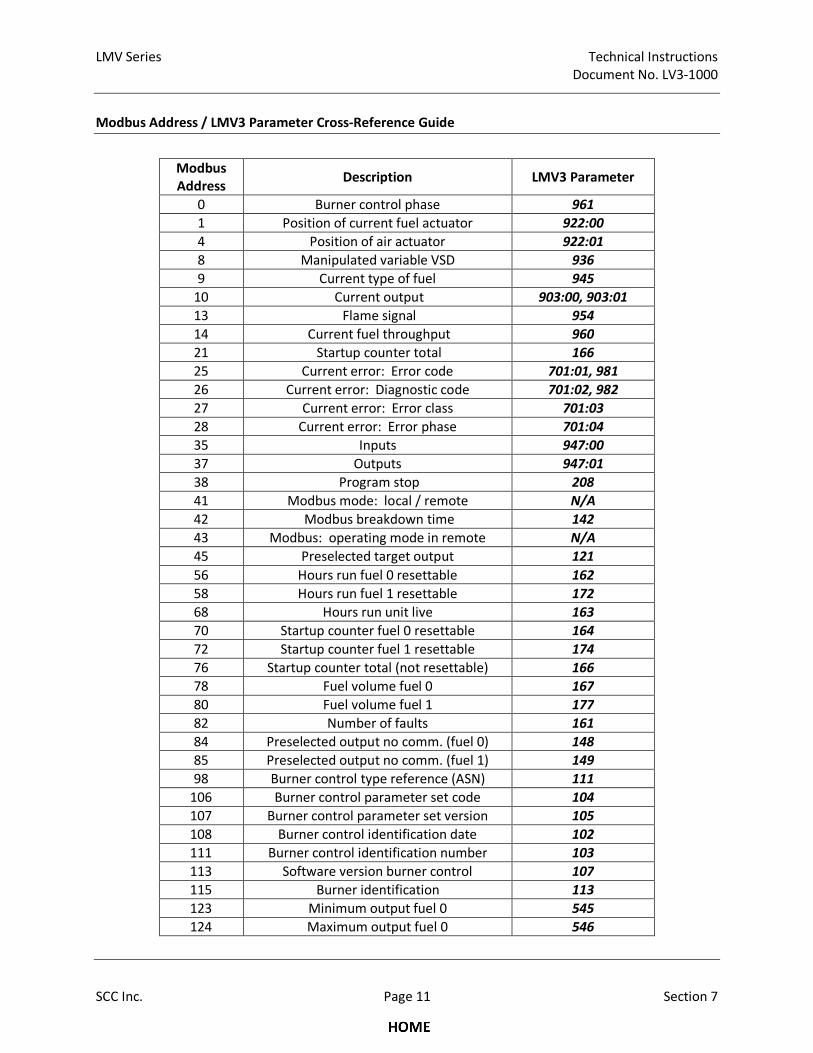
LMV Series Technical Instructions
Document No. LV3-1000
SCC Inc. Page 11 Section 7
Modbus Address / LMV3 Parameter Cross-Reference Guide
Modbus
Address Description LMV3 Parameter
0 Burner control phase 961
1 Position of current fuel actuator 922:00
4 Position of air actuator 922:01
8 Manipulated variable VSD 936
9 Current type of fuel 945
10 Current output 903:00, 903:01
13 Flame signal 954
14 Current fuel throughput 960
21 Startup counter total 166
25 Current error: Error code 701:01, 981
26 Current error: Diagnostic code 701:02, 982
27 Current error: Error class 701:03
28 Current error: Error phase 701:04
35 Inputs 947:00
37 Outputs 947:01
38 Program stop 208
41 Modbus mode: local / remote N/A
42 Modbus breakdown time 142
43 Modbus: operating mode in remote N/A
45 Preselected target output 121
56 Hours run fuel 0 resettable 162
58 Hours run fuel 1 resettable 172
68 Hours run unit live 163
70 Startup counter fuel 0 resettable 164
72 Startup counter fuel 1 resettable 174
76 Startup counter total (not resettable) 166
78 Fuel volume fuel 0 167
80 Fuel volume fuel 1 177
82 Number of faults 161
84 Preselected output no comm. (fuel 0) 148
85 Preselected output no comm. (fuel 1) 149
98 Burner control type reference (ASN) 111
106 Burner control parameter set code 104
107 Burner control parameter set version 105
108 Burner control identification date 102
111 Burner control identification number 103
113 Software version burner control 107
115 Burner identification 113
123 Minimum output fuel 0 545
124 Maximum output fuel 0 546
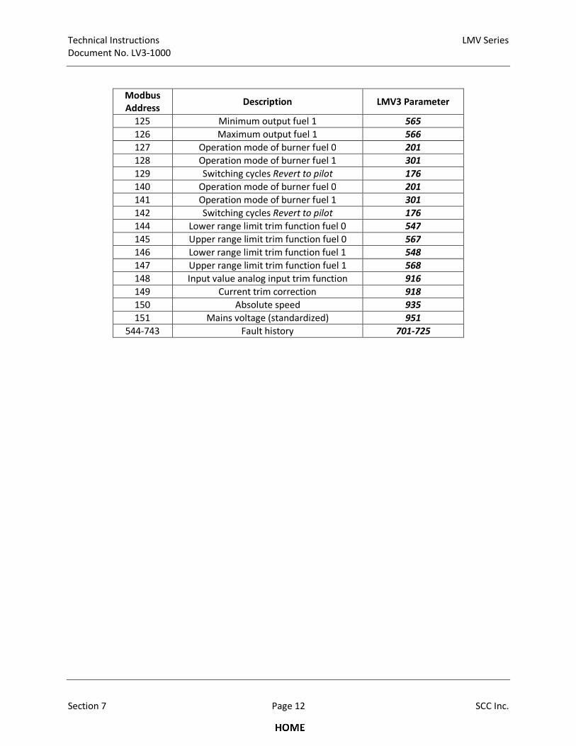
Technical Instructions LMV Series
Document No. LV3-1000
Section 7 Page 12 SCC Inc.
Modbus
Address Description LMV3 Parameter
125 Minimum output fuel 1 565
126 Maximum output fuel 1 566
127 Operation mode of burner fuel 0 201
128 Operation mode of burner fuel 1 301
129 Switching cycles Revert to pilot 176
140 Operation mode of burner fuel 0 201
141 Operation mode of burner fuel 1 301
142 Switching cycles Revert to pilot 176
144 Lower range limit trim function fuel 0 547
145 Upper range limit trim function fuel 0 567
146 Lower range limit trim function fuel 1 548
147 Upper range limit trim function fuel 1 568
148 Input value analog input trim function 916
149 Current trim correction 918
150 Absolute speed 935
151 Mains voltage (standardized) 951
544-743 Fault history 701-725

LMV Series Technical Instructions
Document No. LV3-1000
SCC Inc. Page 13 Section 7
Changeover of controller operating mode
Technical Instructions LMV Series
Document No. LV3-1000
Section 7 Page 14 SCC Inc.
Operating Modes
Changing between
«local» and
«remote» mode
After activating Modbus communication, data can be exchanged between the
LMV3 and the Modbus master via the Modbus interface.
Preselection of the target output via Modbus can only be made after the Modbus
mode has been switched from «local» to «remote». This change is made by
writing to Modbus address 41.
The preselection of the target output that was made previously has no impact and
is set «invalid» when changing to remote operation.
The presetting after activation of Modbus communication is «local». When the
LMV3 is switched off, the mode is set back to the presetting.
Changeover of
Modbus operating
mode between
«auto», «remote
on», and
«remote off»
This setting is used to determine the behavior of the system in remote operation.
The setting is made by writing to Modbus address 43.
With the «auto» setting, the output to be delivered is determined by the LMV3.
With the «remote on» setting, the Modbus master determines the output to be
delivered by the system by predefining a target output.
With the «remote off» setting, the burner will be shut down. A new start is made
only when the operating mode changes to «remote on» and a new preselection of
target output is made, or after a change to local operation.
For output preselection via the building automation and control system, the
controller on contact on the LMV3 must be closed.
The presetting after activation of remote operation is «auto». When the LMV3 is
switched off, the operating mode will be reset to the preselected mode.
Monitoring of
Modbus timeout
If communication between the Modbus and the LMV3 is interrupted, the length
of time that the interruption lasts will be monitored. Every permissible Modbus
communication on the LMV3 will restart monitoring.
Monitoring only takes place in «remote» operation. If the time parameterized for
communication timeout (Modbus address 42) is exceeded, a change from remote
to local operation will take place. In that case, the system travels to the
parameterized preselected output to be delivered in the event of a
communication breakdown (Modbus address 84/85).
� If the time is exceeded, remote operation must be selected again by the Modbus
master. Upon a return of communication, addresses 41 and 43 and the
preselected output must be written again. Only then can the output be
readjusted. Timeout is a Modbus parameter and is retained even if the LMV3 is
switched off.
Bus behavior in the event of burner lockout
If the LMV3 has triggered a lockout due to a fault, the selected operating mode with remote mode
(Modbus addresses 41 and 43) will be retained when the unit is reset. For the required target output to
be reached, all that is required is to preselect the output again via Modbus address 45.
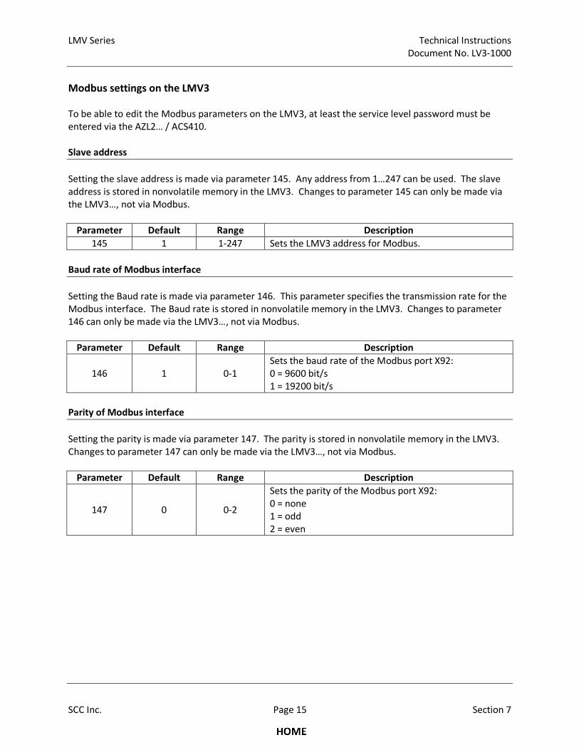
LMV Series Technical Instructions
Document No. LV3-1000
SCC Inc. Page 15 Section 7
Modbus settings on the LMV3
To be able to edit the Modbus parameters on the LMV3, at least the service level password must be
entered via the AZL2… / ACS410.
Slave address
Setting the slave address is made via parameter 145. Any address from 1…247 can be used. The slave
address is stored in nonvolatile memory in the LMV3. Changes to parameter 145 can only be made via
the LMV3…, not via Modbus.
Parameter Default Range Description
145 1 1-247 Sets the LMV3 address for Modbus.
Baud rate of Modbus interface
Setting the Baud rate is made via parameter 146. This parameter specifies the transmission rate for the
Modbus interface. The Baud rate is stored in nonvolatile memory in the LMV3. Changes to parameter
146 can only be made via the LMV3…, not via Modbus.
Parameter Default Range Description
146 1 0-1
Sets the baud rate of the Modbus port X92:
0 = 9600 bit/s
1 = 19200 bit/s
Parity of Modbus interface
Setting the parity is made via parameter 147. The parity is stored in nonvolatile memory in the LMV3.
Changes to parameter 147 can only be made via the LMV3…, not via Modbus.
Parameter Default Range Description
147 0 0-2
Sets the parity of the Modbus port X92:
0 = none
1 = odd
2 = even
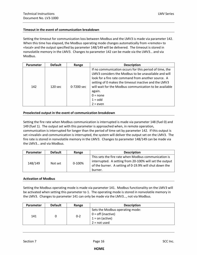
Technical Instructions LMV Series
Document No. LV3-1000
Section 7 Page 16 SCC Inc.
Timeout in the event of communication breakdown
Setting the timeout for communication loss between Modbus and the LMV3 is made via parameter 142.
When this time has elapsed, the Modbus operating mode changes automatically from «remote» to
«local» and the output specified by parameter 148/149 will be delivered. The timeout is stored in
nonvolatile memory in the LMV3. Changes to parameter 142 can be made via the LMV3… and via
Modbus.
Parameter Default Range Description
142 120 sec 0-7200 sec
If no communication occurs for this period of time, the
LMV3 considers the Modbus to be unavailable and will
look for a fire rate command from another source. A
setting of 0 makes the timeout inactive and the LMV3
will wait for the Modbus communication to be available
again.
0 = none
1 = odd
2 = even
Preselected output in the event of communication breakdown
Setting the fire rate when Modbus communication is interrupted is made via parameter 148 (fuel 0) and
149 (fuel 1). The output set with this parameter is approached when, in remote operation,
communication is interrupted for longer than the period of time set by parameter 142. If this output is
set «invalid» and communication is interrupted, the system will deliver the output set on the LMV3. The
fire rate is stored in nonvolatile memory in the LMV3. Changes to parameter 148/149 can be made via
the LMV3… and via Modbus.
Parameter Default Range Description
148/149 Not set 0-100%
This sets the fire rate when Modbus communication is
interrupted. A setting from 20-100% will set the output
of the burner. A setting of 0-19.9% will shut down the
burner.
Activation of Modbus
Setting the Modbus operating mode is made via parameter 141. Modbus functionality on the LMV3 will
be activated when setting this parameter to 1. The operating mode is stored in nonvolatile memory in
the LMV3. Changes to parameter 141 can only be made via the LMV3…, not via Modbus.
Parameter Default Range Description
141 0 0-2
Sets the Modbus operating mode:
0 = off (inactive)
1 = on (active)
2 = not used
LMV Series Technical Instructions
Document No. LV3-1000
SCC Inc. Page 17 Section 7
Modbus in connection with ACS410 / AZL2…
If the ACS410 PC tool is being used while writing to the LMV3 via Modbus, it must be taken into
consideration that write access via Modbus will be rejected if, at the same time, the ACS410 also makes
a write access to parameters. Also, the simultaneous setting of a parameter from the AZL2… and the
Modbus master must be avoided, since it would not be possible to predict who is granted the access
right. Write access via Modbus is possible at any time, independent of the AZL2… or ACS410 PC tool.
Error Handling
In the event of erroneous telegrams (CRC errors, etc.), the AZL2… does not send an exception code
(refer to Modbus definition), but ignores the messages. This is because commercially available Modbus
drivers do not normally respond to exception codes.

Technical Instructions LMV Series
Document No. LV3-1000
Section 7 Page 18 SCC Inc.
Intentionally Left Blank
Section 1 Overview
Section 2 Wiring
Section 3 Parameters
Section 4 Commissioning
Section 5 VSD
Section 6 Troubleshooting
Section 7 Modbus
Section 8 ACS410
Appendix A Application Guide

Section 1 Overview
Section 2 Wiring
Section 3 Parameters
Section 4 Commissioning
Section 5 VSD
Section 6 Troubleshooting
Section 7 Modbus
Section 8 ACS410
Appendix A Application Guide
LMV Series Technical Instructions
Document No. LV3-1000
SCC Inc. Page 1 Section 8
Section 8-1: ACS410 Software Introduction
The LMV3 system can be completely programmed using either the AZL23 or a PC with the
ACS410 software. Most people find that using the AZL23 is more convenient than the ACS410
for a “manual” setup of the LMV3 parameters. However, the ACS410 has additional capabilities
that are not available with the AZL23 / LMV3 alone. These additional, valuable capabilities are:
1. Saving and printing all LMV3 settings, combustion curves, and information in a report
format. This provides a convenient, comprehensive startup report.
2. Saving and uploading entire LMV3 parameter sets to or from a PC.
3. Viewing and saving trends.
4. Viewing a status screen of the LMV3 inputs and outputs as well as the LMV3 operating
state.
5. Setting and visualization of fuel-air ratio curves
The following pages will cover the software installation and how to connect the LMV3 to a PC,
as well as explain how to utilize the basic capabilities of the ACS410 software, including
parameter sets, startup reports, trending, and the status screen.
Since most people prefer to use the AZL23 to set parameters and combustions curves in the
LMV3, the procedure to do this with ACS410 will not be covered in this guide. For technical
information about how to program the LMV3 through the ACS410 software, email
[email protected] or go to www.scccombustion.com/lmv3.htm and click on
“ACS410 Software Operating Instructions”.
The ACS410 software can be used with the following PC operating systems:
• Windows XP (service pack 2 minimum)
• Windows 7
• Windows 8.1
• Windows 10
ACS410 cannot be used with the following PC operating systems:
• Windows Vista
• Windows ME

Technical Instructions LMV Series
Document No. LV3-1000
Section 8 Page 2 SCC Inc.
Section 8-2: Software Installation
The following steps outline the procedure for installing the ACS410 software on a PC.
1. The ACS410 software can be downloaded from the SCC website:
a. Go to www.scccombustion.com/lmv3.htm.
b. Click on “ACS410 Software (21MB)” towards the bottom to begin the download.
2. Once the ACS410 software has been downloaded, double-click on the setup.exe file. This
should start the installation. Pick the desired options as the installation prompts:
a. Select the installation language and click “OK”.
b. When prompted, click “Next”.
c. Accept the license agreement and click “Next”.
d. Select the folder where the ACS410 software will be installed. The default folder is
C:\Program Files (x86)\Siemens\ACS410. Click “Next”.
e. Select the folder where the ACS410 software shortcuts will be installed in the Start
Menu. The default folder is ACS410. Click “Next”.
f. Select the checkbox if an ACS410 desktop icon is desired. Click “Next”.
g. Review the installation choices. If everything looks correct, click “Install”.
h. The ACS410 software will now be installed on the PC.
3. Once the ACS410 software installation is complete, a prompt to install the OCI410 device
drivers will appear. Perform the following steps to install these drivers:
a. Click “Next”.
b. The OCI410 drivers will now be installed.
c. Once the OCI410 drivers have been installed successfully, click “Finish”.
d. Select the checkbox if it is desired for ACS410 to launch immediately, then click “Finish”.
4. At this point, the ACS410 software is ready to run.
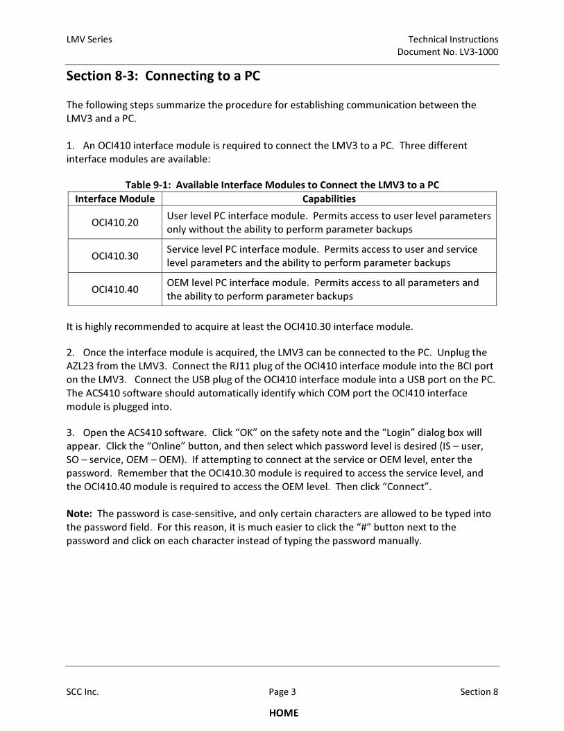
LMV Series Technical Instructions
Document No. LV3-1000
SCC Inc. Page 3 Section 8
Section 8-3: Connecting to a PC
The following steps summarize the procedure for establishing communication between the
LMV3 and a PC.
1. An OCI410 interface module is required to connect the LMV3 to a PC. Three different
interface modules are available:
Table 9-1: Available Interface Modules to Connect the LMV3 to a PC
Interface Module Capabilities
OCI410.20 User level PC interface module. Permits access to user level parameters
only without the ability to perform parameter backups
OCI410.30 Service level PC interface module. Permits access to user and service
level parameters and the ability to perform parameter backups
OCI410.40 OEM level PC interface module. Permits access to all parameters and
the ability to perform parameter backups
It is highly recommended to acquire at least the OCI410.30 interface module.
2. Once the interface module is acquired, the LMV3 can be connected to the PC. Unplug the
AZL23 from the LMV3. Connect the RJ11 plug of the OCI410 interface module into the BCI port
on the LMV3. Connect the USB plug of the OCI410 interface module into a USB port on the PC.
The ACS410 software should automatically identify which COM port the OCI410 interface
module is plugged into.
3. Open the ACS410 software. Click “OK” on the safety note and the “Login” dialog box will
appear. Click the “Online” button, and then select which password level is desired (IS – user,
SO – service, OEM – OEM). If attempting to connect at the service or OEM level, enter the
password. Remember that the OCI410.30 module is required to access the service level, and
the OCI410.40 module is required to access the OEM level. Then click “Connect”.
Note: The password is case-sensitive, and only certain characters are allowed to be typed into
the password field. For this reason, it is much easier to click the “#” button next to the
password and click on each character instead of typing the password manually.

Technical Instructions LMV Series
Document No. LV3-1000
Section 8 Page 4 SCC Inc.
Section 8-4: Saving a Parameter Set to a PC
The following steps outline the procedure for saving parameter sets to a PC.
1. Ensure that the ACS410 software is open, and the PC is connected to the LMV3 at the
service or OEM level. See previous sections if necessary. The LMV3 must have a burner ID in
order to perform a parameter backup. The burner ID is set via parameter 113.
2. Click on the “Backup / Restore” tab. Click on “Backup” in the lower right corner.
3. A box will appear called “Backup description”. The default file name is the current date and
time. It is highly recommended to change the file name to something more job-specific.
Additionally, information can be added for description, device number, burner type, and burner
serial number. Once all of the relevant information has been entered, click “OK”.
4. After about a minute, a box should appear stating that the backup was successful and the
backup file should now be listed on the screen. The default location for storing parameter sets
is C:\Program Files (x86)\Siemens\ACS410\bkp. Notice that two files are created in this folder:
one with a .bkp file extension and one with a .unl file extension. Both files are necessary in
order to view the parameter set or restore it to an LMV3.
Note: The parameter set is stored in machine language, so it is not useful as a startup report.
See the following section called “Creating an LMV3 Startup Report” for the procedure for
creating and printing a comprehensive startup report.
LMV Series Technical Instructions
Document No. LV3-1000
SCC Inc. Page 5 Section 8
Section 8-5: Uploading a Parameter Set to an LMV3
The following steps outline the procedure for uploading parameter sets from a PC to an LMV3.
1. Ensure that the ACS410 software is open, and the PC is connected to the LMV3 at the
service or OEM level. See previous sections if necessary.
2. Click on the “Backup / Restore” tab. A list of stored parameter sets will display on the
screen. Select the parameter set to be uploaded into the LMV3 and click on “Restore” in the
lower right corner. This file will overwrite the parameter set on the LMV3 and will determine
the behavior of the LMV3. Be sure that the correct file is selected.
3. A prompt will appear asking to confirm that the proper file was selected. Click “Yes”. After
about a minute, a box should appear stating that the upload was successful. If an error
message is returned, see below for the cause of the error:
Burner ID: The burner ID of the data set stored on the PC does not match the burner ID of the
LMV3. View the burner ID (parameter 113) of the stored parameter set and ensure that it
matches the burner ID displayed by parameter 113 on the LMV3.
Incompatible parameter sets: The current software version of the LMV3 is not compatible with
the software version of the parameter set stored on the PC.
Different types of units: It is not possible to copy the parameter set from an LMV36 to an
LMV37, and vice versa.
Technical Instructions LMV Series
Document No. LV3-1000
Section 8 Page 6 SCC Inc.
Section 8-6: Creating an LMV3 Startup Report
The following steps outline the procedure for saving, viewing, and printing a startup report to a
PC.
1. Open the ACS410 software. Instead of logging in, click the “Offline” button. Then click the
“Backup” button and press “OK”. The ACS410 is now in offline mode and not communicating
with the LMV3.
2. The screen should list all of the parameter backups that have previously been made. If a
new parameter backup needs to be made before creating the startup report, see the previous
section called “Saving a Parameter Set to a PC”.
3. Select the parameter set to be used for creating the startup report. Then click on “Load” in
the lower right corner.
4. The “Info / Service” tab will now display all of the user level parameters and the fault
history of the selected parameter set. The “Parameters” tab will display all of the service and
OEM level parameters of the selected parameter set.
5. Select the “File” dropdown menu, and click on “Report”. Enter a description of the
parameter set if desired, then click on “OK” to generate the startup report.
6. A print preview of the startup report will be displayed. The startup report displays every
parameter setting, the fault history, and the fuel-air ratio curves.
7. To print the startup report, click “Print”. The startup report can also be saved in PDF format
by printing it to a PDF writer. Most people prefer to have a PDF file of the parameter list, fault
history, and fuel-air ratio curves. These pieces provide a very inclusive LMV3 startup report.
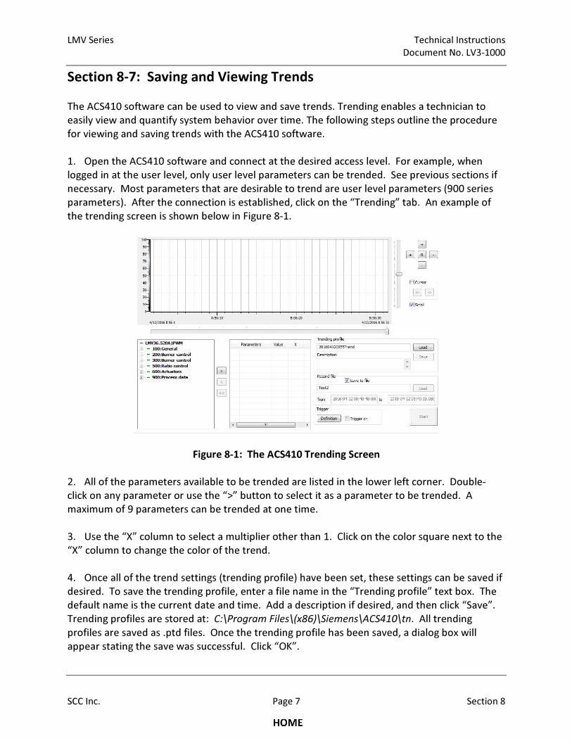
LMV Series Technical Instructions
Document No. LV3-1000
SCC Inc. Page 7 Section 8
Section 8-7: Saving and Viewing Trends
The ACS410 software can be used to view and save trends. Trending enables a technician to
easily view and quantify system behavior over time. The following steps outline the procedure
for viewing and saving trends with the ACS410 software.
1. Open the ACS410 software and connect at the desired access level. For example, when
logged in at the user level, only user level parameters can be trended. See previous sections if
necessary. Most parameters that are desirable to trend are user level parameters (900 series
parameters). After the connection is established, click on the “Trending” tab. An example of
the trending screen is shown below in Figure 8-1.
Figure 8-1: The ACS410 Trending Screen
2. All of the parameters available to be trended are listed in the lower left corner. Double-
click on any parameter or use the “>” button to select it as a parameter to be trended. A
maximum of 9 parameters can be trended at one time.
3. Use the “X” column to select a multiplier other than 1. Click on the color square next to the
“X” column to change the color of the trend.
4. Once all of the trend settings (trending profile) have been set, these settings can be saved if
desired. To save the trending profile, enter a file name in the “Trending profile” text box. The
default name is the current date and time. Add a description if desired, and then click “Save”.
Trending profiles are stored at: C:\Program Files\(x86)\Siemens\ACS410\tn. All trending
profiles are saved as .ptd files. Once the trending profile has been saved, a dialog box will
appear stating the save was successful. Click “OK”.
Technical Instructions LMV Series
Document No. LV3-1000
Section 8 Page 8 SCC Inc.
5. Before starting the trend, click on the “Save to file” check box if the trending data is to be
stored to a file. Enter a file name in the provided text box. The default name is the current
date and time.
6. Click the “Start” button to start the trending. Use the “+” and “-” buttons to adjust the scale
of the trend, or click the “0” button to return to the initial scale. Check the “Cursor” check box
to add a double line showing the cursor and to open a pop-up window showing the exact values
of the selected parameters. When the “Cursor” button is checked, the “<-” and “->” buttons
can be used to change the cursor’s position and update the values in the pop-up window
accordingly.
7. The trend will be buffered until the “Stop” button is clicked. The trending data will now be
saved under the file name created in step 5. Trending data is stored in the following location:
C:\Program Files (x86)\Siemens\ACS410\tn. Each set of trending data creates two files: one
with a .unl format and one with a .dtd format. Both files are necessary if the trend is to be
viewed at a later time through the ACS410 software.
8. To view a previously saved trend through the ACS410 software, click “Login” at the top of
the screen. Click the “Offline” button, then the “Trending” button, and then click “OK”. A list of
the saved trending data sets will appear. Choose the trending data that is to be viewed and
click “Load”.
9. To open previously saved trending data in Microsoft Excel, first open Microsoft Excel. Click
on “File” and then click “Open”. Navigate to the C:\Program Files (x86)\Siemens\ACS410\tn
folder, and open the .dtd file corresponding to the trending data to be opened. If the .dtd file
does not appear, select “All Files” in the dropdown menu in the lower right corner to ensure all
file types are displayed. Once the .dtd file is opened, the trending data will be displayed in a
clear, readable format.
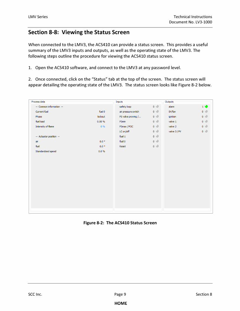
LMV Series Technical Instructions
Document No. LV3-1000
SCC Inc. Page 9 Section 8
Section 8-8: Viewing the Status Screen
When connected to the LMV3, the ACS410 can provide a status screen. This provides a useful
summary of the LMV3 inputs and outputs, as well as the operating state of the LMV3. The
following steps outline the procedure for viewing the ACS410 status screen.
1. Open the ACS410 software, and connect to the LMV3 at any password level.
2. Once connected, click on the “Status” tab at the top of the screen. The status screen will
appear detailing the operating state of the LMV3. The status screen looks like Figure 8-2 below.
Figure 8-2: The ACS410 Status Screen

Technical Instructions LMV Series
Document No. LV3-1000
Section 8 Page 10 SCC Inc.
Intentionally Left Blank

Section 1 Overview
Section 2 Wiring
Section 3 Parameters
Section 4 Commissioning
Section 5 VSD
Section 6 Troubleshooting
Section 7 Modbus
Section 8 ACS410
Appendix A Application Guide
Section 1 Overview
Section 2 Wiring
Section 3 Parameters
Section 4 Commissioning
Section 5 VSD
Section 6 Troubleshooting
Section 7 Modbus
Section 8 ACS410
Appendix A Application Guide
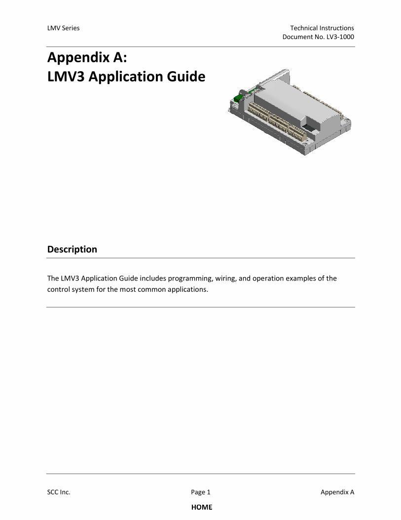
LMV Series Technical Instructions
Document No. LV3-1000
SCC Inc. Page 1 Appendix A
Appendix A:
LMV3 Application Guide
Description
The LMV3 Application Guide includes programming, wiring, and operation examples of the
control system for the most common applications.
Technical Instructions LMV Series
Document No. LV3-1000
Appendix A Page 2 SCC Inc.
Table of Contents
Fresh Air Damper
Introduction ........................................................................................................................... 4
Procedure .............................................................................................................................. 4
Operation .............................................................................................................................. 5
Important Notes .................................................................................................................... 5
Hot Standby on a Steam Boiler with an RWF55
Introduction ........................................................................................................................... 6
Procedure .............................................................................................................................. 6
Operation .............................................................................................................................. 7
Important Notes .................................................................................................................... 7
Low Fire Hold with an RWF55
Introduction ........................................................................................................................... 8
Procedure - Steam Boiler with an RWF55 with Analog Output ............................................... 9
Procedure - Hot Water Boiler with an RWF55 with Analog Output ....................................... 10
Procedure - Steam Boiler with an RWF55 with 3-position Output (LMV37 only) .................. 11
Procedure - Hot Water Boiler with an RWF55 with 3-position Output (LMV37 only) ............ 12
Operation ............................................................................................................................ 13
Example ............................................................................................................................... 13
Pilot Valve Proving
Introduction ......................................................................................................................... 14
Procedure ............................................................................................................................ 14
Option 1: On Startup with SKP25’s on both the Pilot and Main Gas Trains .......................... 16
Sequence of Operation ................................................................................................... 17
Important Notes ............................................................................................................. 17
Option 2: On Startup, SKP25 on the Main Gas Train, Solenoid Valves on the Pilot Train ...... 18
Sequence of Operation ................................................................................................... 19
Important Notes ............................................................................................................. 19
Option 3: Pilot Valve Proving on Startup and Main Valve Proving on Shutdown .................. 20
Sequence of Operation ................................................................................................... 21
Important Notes ............................................................................................................. 21
LMV Series Technical Instructions
Document No. LV3-1000
SCC Inc. Page 3 Appendix A
Table of Contents (continued)
Purge Proving
Introduction ......................................................................................................................... 22
Procedure ............................................................................................................................ 22
Operation ............................................................................................................................ 23
Revert to Pilot - LMV37 only
Introduction ......................................................................................................................... 24
Procedure ............................................................................................................................ 24
Sequence of Operation ........................................................................................................ 25
Operation Example ............................................................................................................... 27
Important Notes .................................................................................................................. 28
Stack Damper
Introduction ......................................................................................................................... 29
Procedure ............................................................................................................................ 29
Operation ............................................................................................................................ 30
Important Notes .................................................................................................................. 30
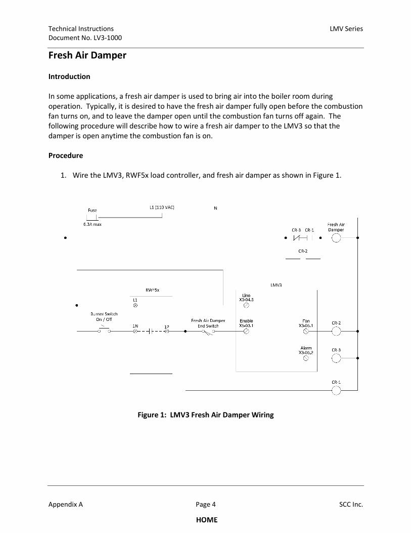
Technical Instructions LMV Series
Document No. LV3-1000
Appendix A Page 4 SCC Inc.
Fresh Air Damper
Introduction
In some applications, a fresh air damper is used to bring air into the boiler room during
operation. Typically, it is desired to have the fresh air damper fully open before the combustion
fan turns on, and to leave the damper open until the combustion fan turns off again. The
following procedure will describe how to wire a fresh air damper to the LMV3 so that the
damper is open anytime the combustion fan is on.
Procedure
1. Wire the LMV3, RWF5x load controller, and fresh air damper as shown in Figure 1.
Figure 1: LMV3 Fresh Air Damper Wiring
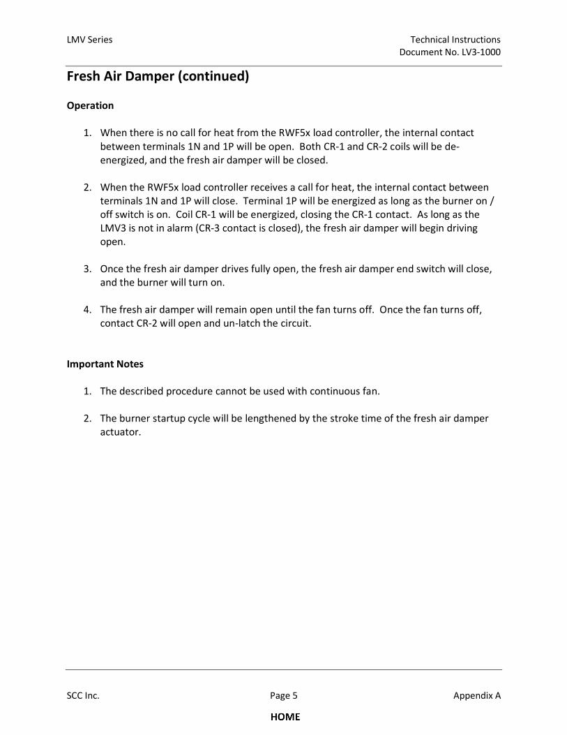
LMV Series Technical Instructions
Document No. LV3-1000
SCC Inc. Page 5 Appendix A
Fresh Air Damper (continued)
Operation
1. When there is no call for heat from the RWF5x load controller, the internal contact
between terminals 1N and 1P will be open. Both CR-1 and CR-2 coils will be de-
energized, and the fresh air damper will be closed.
2. When the RWF5x load controller receives a call for heat, the internal contact between
terminals 1N and 1P will close. Terminal 1P will be energized as long as the burner on /
off switch is on. Coil CR-1 will be energized, closing the CR-1 contact. As long as the
LMV3 is not in alarm (CR-3 contact is closed), the fresh air damper will begin driving
open.
3. Once the fresh air damper drives fully open, the fresh air damper end switch will close,
and the burner will turn on.
4. The fresh air damper will remain open until the fan turns off. Once the fan turns off,
contact CR-2 will open and un-latch the circuit.
Important Notes
1. The described procedure cannot be used with continuous fan.
2. The burner startup cycle will be lengthened by the stroke time of the fresh air damper
actuator.
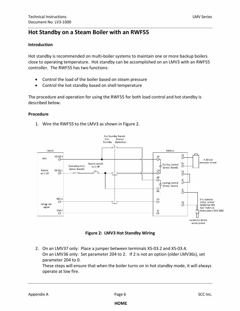
Technical Instructions LMV Series
Document No. LV3-1000
Appendix A Page 6 SCC Inc.
Hot Standby on a Steam Boiler with an RWF55
Introduction
Hot standby is recommended on multi-boiler systems to maintain one or more backup boilers
close to operating temperature. Hot standby can be accomplished on an LMV3 with an RWF55
controller. The RWF55 has two functions:
• Control the load of the boiler based on steam pressure
• Control the hot standby based on shell temperature
The procedure and operation for using the RWF55 for both load control and hot standby is
described below.
Procedure
1. Wire the RWF55 to the LMV3 as shown in Figure 2.
Figure 2: LMV3 Hot Standby Wiring
2. On an LMV37 only: Place a jumper between terminals X5-03.2 and X5-03.4.
On an LMV36 only: Set parameter 204 to 2. If 2 is not an option (older LMV36s), set
parameter 204 to 0.
These steps will ensure that when the boiler turns on in hot standby mode, it will always
operate at low fire.
LMV Series Technical Instructions
Document No. LV3-1000
SCC Inc. Page 7 Appendix A
Hot Standby on a Steam Boiler with an RWF55 (continued)
3. Set the following parameters in the RWF55 controller. For more information, obtain
Siemens Document No. U7867 for the RWF55 at www.scccombustion.com.
ConF > Cntr > CtYP = 2
ConF > Cntr > SPL = setpoint range lower limit
ConF > Cntr > SPH = setpoint range upper limit
OPr > SP1 = normal operation setpoint
PArA > HYS1 = burner on for normal operation (pressure-based)
PArA > HYS3 = burner off for normal operation (pressure-based)
ConF > InP > InP1 > SEn1 = pressure sensor type
ConF > InP > lnP1 > SCL1 = 0
ConF > InP > InP1 > SCH1 = high end of the range of the pressure sensor
ConF > InP > InP3 > SEn3 = temperature sensor type
ConF > Inp > Inp3 > dF3 = 0
ConF > AF > FnCt = 12
ConF > AF > AL = hot standby setpoint (temperature-based)
ConF > AF > HYSt = burner on / off for hot standby (temperature-based)
ConF > OutP > SiGn = 1
Operation
1. When the hot standby switch is set for hot standby, the LMV3 system is in hot standby
mode. The burner will turn on and off based on the temperature limits set in the
RWF55 controller for hot standby (ConF > AF). Since the signal to LMV3 terminal X64.1 is
broken by the hot standby switch, the LMV3 stays at low fire until the burner turns off
based on the burner off point set in the RWF55.
2. When the hot standby switch is set for normal operation, the system is in normal
operation mode and not in hot standby. The burner will turn on and off based on the
pressure limits set in the RWF55 controller for normal operation (PArA > HYS1 and PArA
> HYS3). The signal to LMV3 terminal X64.1 determines the firing rate of the burner.
Important Notes
1. An RWF55 controller must be used (not RWF50).
2. The RWF55 is operating as the load controller during normal operation as well as
controlling the hot standby.
Technical Instructions LMV Series
Document No. LV3-1000
Appendix A Page 8 SCC Inc.
Low Fire Hold with an RWF55
Introduction
Low fire hold assists in preventing boiler damage from thermal shock. If an RWF55 is the load
controller with the LMV3, a low fire hold can be easily incorporated. With an RWF55, a low fire
hold is accomplished by breaking the increase load signal to the LMV3. The wiring and setup
for four cases will be described:
• Steam boiler with an RWF55 with analog output
• Hot water boiler with an RWF55 with analog output
• Steam boiler with an RWF55 with 3-position output (LMV37 only)
• Hot water boiler with an RWF55 with 3-position output (LMV37 only)
The wiring and setup of the RWF55 differs slightly depending on the mode selected as shown
on the following pages.
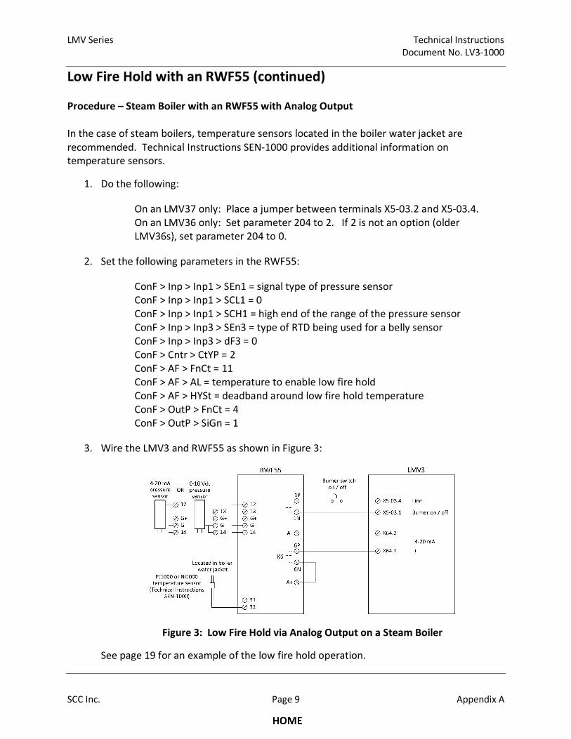
LMV Series Technical Instructions
Document No. LV3-1000
SCC Inc. Page 9 Appendix A
Low Fire Hold with an RWF55 (continued)
Procedure – Steam Boiler with an RWF55 with Analog Output
In the case of steam boilers, temperature sensors located in the boiler water jacket are
recommended. Technical Instructions SEN-1000 provides additional information on
temperature sensors.
1. Do the following:
On an LMV37 only: Place a jumper between terminals X5-03.2 and X5-03.4.
On an LMV36 only: Set parameter 204 to 2. If 2 is not an option (older
LMV36s), set parameter 204 to 0.
2. Set the following parameters in the RWF55:
ConF > Inp > Inp1 > SEn1 = signal type of pressure sensor
ConF > Inp > Inp1 > SCL1 = 0
ConF > Inp > Inp1 > SCH1 = high end of the range of the pressure sensor
ConF > Inp > Inp3 > SEn3 = type of RTD being used for a belly sensor
ConF > Inp > Inp3 > dF3 = 0
ConF > Cntr > CtYP = 2
ConF > AF > FnCt = 11
ConF > AF > AL = temperature to enable low fire hold
ConF > AF > HYSt = deadband around low fire hold temperature
ConF > OutP > FnCt = 4
ConF > OutP > SiGn = 1
3. Wire the LMV3 and RWF55 as shown in Figure 3:
Figure 3: Low Fire Hold via Analog Output on a Steam Boiler
See page 19 for an example of the low fire hold operation.
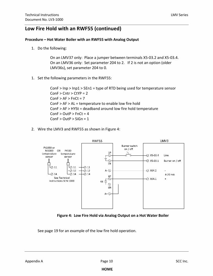
Technical Instructions LMV Series
Document No. LV3-1000
Appendix A Page 10 SCC Inc.
Low Fire Hold with an RWF55 (continued)
Procedure – Hot Water Boiler with an RWF55 with Analog Output
1. Do the following:
On an LMV37 only: Place a jumper between terminals X5-03.2 and X5-03.4.
On an LMV36 only: Set parameter 204 to 2. If 2 is not an option (older
LMV36s), set parameter 204 to 0.
1. Set the following parameters in the RWF55:
ConF > Inp > Inp1 > SEn1 = type of RTD being used for temperature sensor
ConF > Cntr > CtYP = 2
ConF > AF > FnCt = 7
ConF > AF > AL = temperature to enable low fire hold
ConF > AF > HYSt = deadband around low fire hold temperature
ConF > OutP > FnCt = 4
ConF > OutP > SiGn = 1
2. Wire the LMV3 and RWF55 as shown in Figure 4:
Figure 4: Low Fire Hold via Analog Output on a Hot Water Boiler
See page 19 for an example of the low fire hold operation.
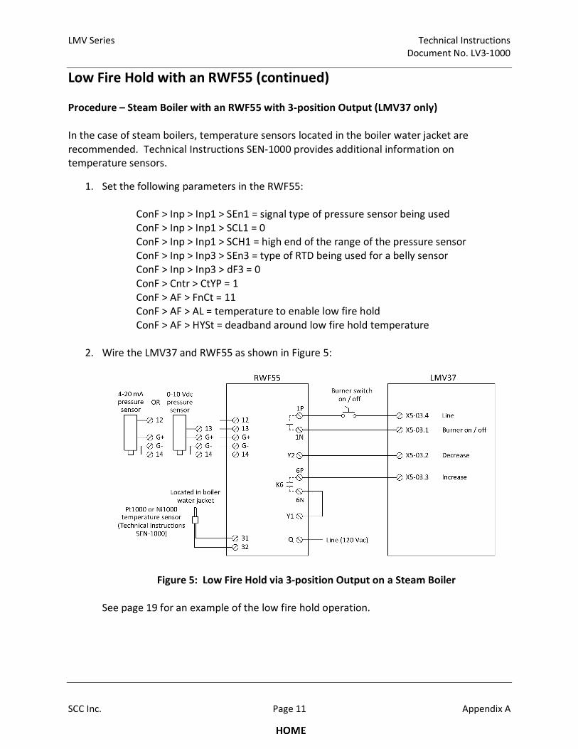
LMV Series Technical Instructions
Document No. LV3-1000
SCC Inc. Page 11 Appendix A
Low Fire Hold with an RWF55 (continued)
Procedure – Steam Boiler with an RWF55 with 3-position Output (LMV37 only)
In the case of steam boilers, temperature sensors located in the boiler water jacket are
recommended. Technical Instructions SEN-1000 provides additional information on
temperature sensors.
1. Set the following parameters in the RWF55:
ConF > Inp > Inp1 > SEn1 = signal type of pressure sensor being used
ConF > Inp > Inp1 > SCL1 = 0
ConF > Inp > Inp1 > SCH1 = high end of the range of the pressure sensor
ConF > Inp > Inp3 > SEn3 = type of RTD being used for a belly sensor
ConF > Inp > Inp3 > dF3 = 0
ConF > Cntr > CtYP = 1
ConF > AF > FnCt = 11
ConF > AF > AL = temperature to enable low fire hold
ConF > AF > HYSt = deadband around low fire hold temperature
2. Wire the LMV37 and RWF55 as shown in Figure 5:
Figure 5: Low Fire Hold via 3-position Output on a Steam Boiler
See page 19 for an example of the low fire hold operation.
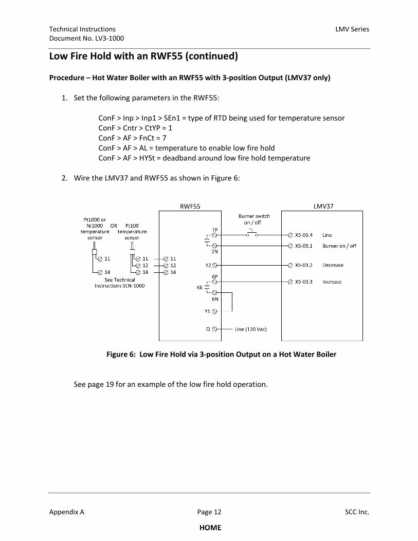
Technical Instructions LMV Series
Document No. LV3-1000
Appendix A Page 12 SCC Inc.
Low Fire Hold with an RWF55 (continued)
Procedure – Hot Water Boiler with an RWF55 with 3-position Output (LMV37 only)
1. Set the following parameters in the RWF55:
ConF > Inp > Inp1 > SEn1 = type of RTD being used for temperature sensor
ConF > Cntr > CtYP = 1
ConF > AF > FnCt = 7
ConF > AF > AL = temperature to enable low fire hold
ConF > AF > HYSt = deadband around low fire hold temperature
2. Wire the LMV37 and RWF55 as shown in Figure 6:
Figure 6: Low Fire Hold via 3-position Output on a Hot Water Boiler
See page 19 for an example of the low fire hold operation.
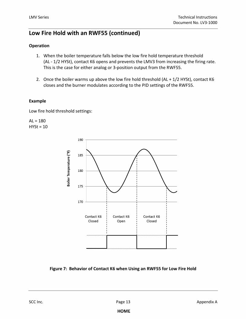
LMV Series Technical Instructions
Document No. LV3-1000
SCC Inc. Page 13 Appendix A
Low Fire Hold with an RWF55 (continued)
Operation
1. When the boiler temperature falls below the low fire hold temperature threshold
(AL - 1/2 HYSt), contact K6 opens and prevents the LMV3 from increasing the firing rate.
This is the case for either analog or 3-position output from the RWF55.
2. Once the boiler warms up above the low fire hold threshold (AL + 1/2 HYSt), contact K6
closes and the burner modulates according to the PID settings of the RWF55.
Example
Low fire hold threshold settings:
AL = 180
HYSt = 10
Figure 7: Behavior of Contact K6 when Using an RWF55 for Low Fire Hold

Technical Instructions LMV Series
Document No. LV3-1000
Appendix A Page 14 SCC Inc.
Pilot Valve Proving
Introduction
Valve proving detects if the main gas valves in a gas train are leaking. In addition to checking
the main gas valves, the pilot valves may be tested for leakage as well. There are three options
for performing pilot valve proving:
• Option 1: On Startup with SKP25’s on both the Pilot and Main Gas Trains
• Option 2: On Startup, SKP25 on the Main Gas Train, Solenoid Valves on the Pilot Train
• Option 3: Pilot Valve Proving on Startup and Main Valve Proving on Shutdown
On the LMV3, valve proving of the main gas valves can be performed during startup, during
shutdown, or during both startup and shutdown of the boiler. If pilot valve proving is added
using Option 1 or Option 2, valve proving must be performed during startup of the boiler only.
If pilot valve proving is added using Option 3, valve proving must be performed during both
startup and shutdown of the boiler.
Pilot valve proving can be performed on any LMV3.
Procedure
1. The valve proving type can be set in the LMV3 using parameter 241. For Option 1 or
Option 2, this must be set to a 1 (valve proving on startup only). For Option 3, this must
be set to a 3 (valve proving on both startup and shutdown).
2. The times for each of the four stages of valve proving need to be set. To do so, use the
following parameters in the LMV3:
Parameter 242 is the time that the downstream valve is energized in order to evacuate
the chamber between the upstream and downstream valves (phase 80). This is typically
set to 3 seconds, but should not be set any less than the opening time of the valves.
Parameter 244 is the time that the upstream valve is energized in order to pressurize
the chamber between the upstream and downstream valves (phase 82). This is typically
set to 3 seconds, but should not be set any less than the opening time of the valves.
Parameter 243 is the time that both the upstream and downstream valves are closed to
test the leakage rate of the upstream valve (phase 81). Parameter 245 is the time that
both the upstream and downstream valves are closed to test the leakage rate of the
downstream valve (phase 83). Both of these times should be set to the same value.
These times can be calculated using the following equation:
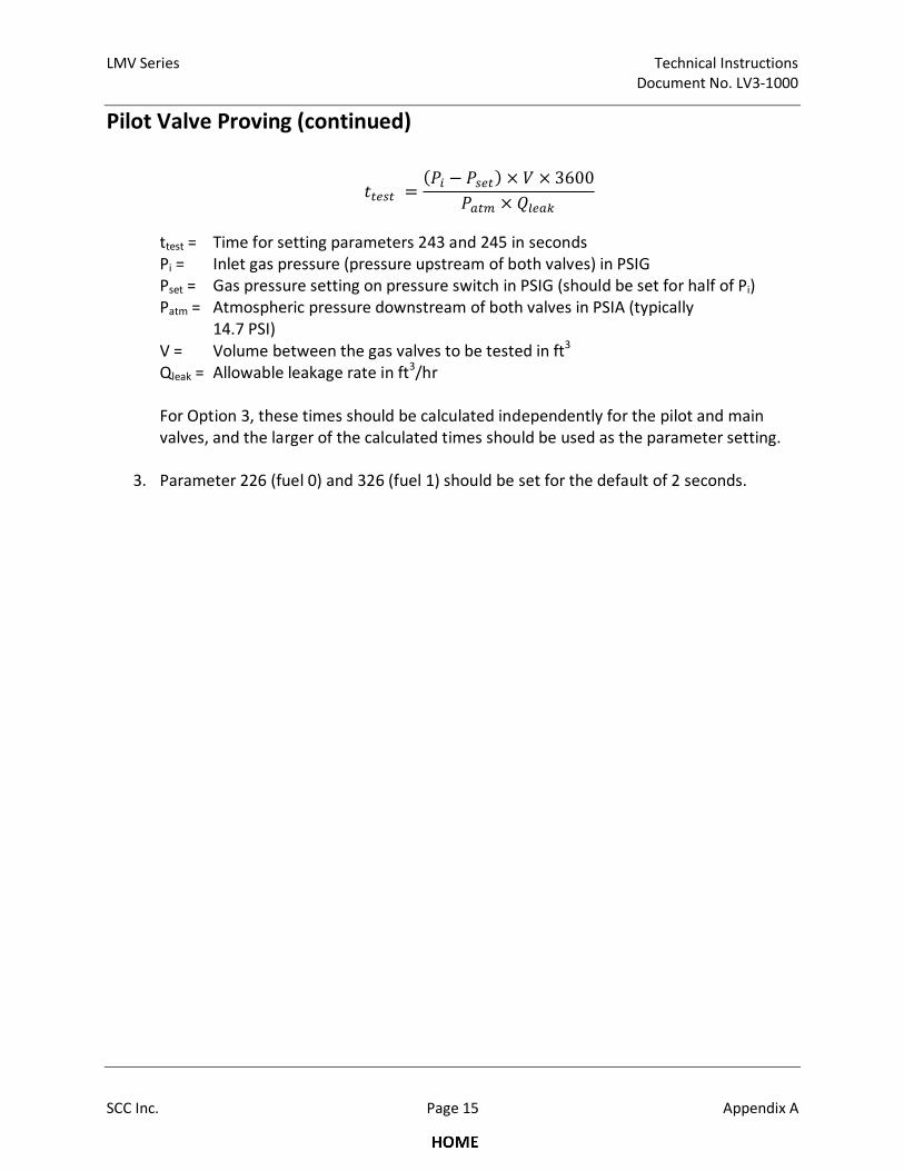
LMV Series Technical Instructions
Document No. LV3-1000
SCC Inc. Page 15 Appendix A
Pilot Valve Proving (continued)
����� =�� − ����� × × 3600
���� × �����
ttest = Time for setting parameters 243 and 245 in seconds
Pi = Inlet gas pressure (pressure upstream of both valves) in PSIG
Pset = Gas pressure setting on pressure switch in PSIG (should be set for half of Pi)
Patm = Atmospheric pressure downstream of both valves in PSIA (typically
14.7 PSI)
V = Volume between the gas valves to be tested in ft3
Qleak = Allowable leakage rate in ft3/hr
For Option 3, these times should be calculated independently for the pilot and main
valves, and the larger of the calculated times should be used as the parameter setting.
3. Parameter 226 (fuel 0) and 326 (fuel 1) should be set for the default of 2 seconds.

Technical Instructions LMV Series
Document No. LV3-1000
Appendix A Page 16 SCC Inc.
Pilot Valve Proving (continued)
Option 1: On Startup with SKP25’s on both the Pilot and Main Gas Trains
Figure 8: Option 1 Piping and Electrical Schematics
LMV Series Technical Instructions
Document No. LV3-1000
SCC Inc. Page 17 Appendix A
Pilot Valve Proving (continued)
Option 1 Sequence of Operation
1. The LMV3 is in standby. All valves are closed and all relay contacts are as shown in the
electrical schematic.
2. The LMV3 receives a call for heat. The SV terminal (X6-03.3) energizes with the blower,
energizing the PVLT (Pilot Valve Leak Test). The PVLT opens, and connects the volumes
between the pilot valves and main valves. The PVLT POC switch also opens, preventing
the operation of the pilot valves.
3. During prepurge, the main valve proving sequence takes place as normal. The PS-VP
(Pressure Switch - Valve Proving) is wired to terminal X9-04.2 as normal. The setpoint of
the PS-VP should be set for half of the inlet pressure.
4. The LMV3 drives to ignition position. The ignition transformer output (X4-02.3)
energizes, thereby energizing the CR-2 coil, and latching the CR-1 coil from the power
supplied from X6-03.3. At the same time, one of the CR-1 contacts opens, thereby
closing the PVLT and closing the PVLT POC switch. Note that the PVLT POC switch must
be closed before the pilot valves open.
5. The LMV3 continues light off and runs as normal, with the CR-1 coil latched in and the
PVLT closed.
6. Upon shutdown, the SV terminal (X6-03.3) de-energizes, which un-latches the circuit.
The PVLT remains closed until the next start up.
Option 1 Important Notes
1. The proof of closure switch on the PVLT ensures that gas is unable to flow between the
pilot and main valves before the pilot attempts to light.
2. All four valves are tested at the inlet pressure, which is the pressure that they normally
operate at. The PS-VP should be set for half of the inlet pressure which provides a valid
test for all four valves.
3. Valve proving must be done on startup only.
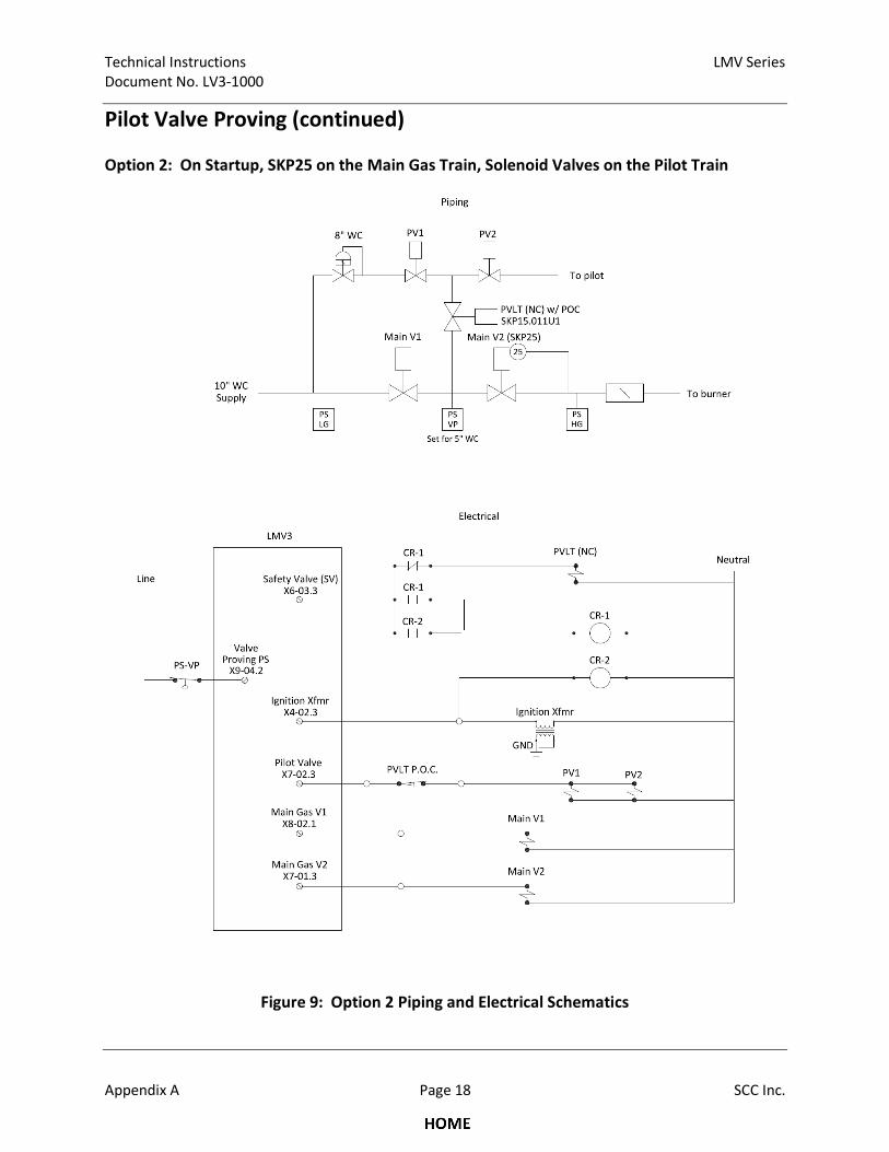
Technical Instructions LMV Series
Document No. LV3-1000
Appendix A Page 18 SCC Inc.
Pilot Valve Proving (continued)
Option 2: On Startup, SKP25 on the Main Gas Train, Solenoid Valves on the Pilot Train
Figure 9: Option 2 Piping and Electrical Schematics

LMV Series Technical Instructions
Document No. LV3-1000
SCC Inc. Page 19 Appendix A
Pilot Valve Proving (continued)
Option 2 Sequence of Operation
1. The LMV3 is in standby. All valves are closed and all relay contacts are as shown in the
electrical schematic.
2. The LMV3 receives a call for heat. The SV terminal (X6-03.3) energizes with the blower,
energizing the PVLT (Pilot Valve Leak Test). The PVLT opens, and connects the volumes
between the pilot valves and main valves. The PVLT POC switch also opens, preventing
the operation of the pilot valves.
3. During prepurge, the main valve proving sequence takes place as normal. The PS-VP
(Pressure Switch - Valve Proving) is wired to terminal X9-04.2 as normal. The setpoint of
the PS-VP should be set for half of the inlet pressure.
4. The LMV3 drives to ignition position. The ignition transformer output (X4-02.3)
energizes, thereby energizing the CR-2 coil, and latching the CR-1 coil from the power
supplied from X6-03.3. At the same time, one of the CR-1 contacts opens, thereby
closing the PVLT and closing the PVLT POC switch. Note that the PVLT POC switch must
be closed before the pilot valves open.
5. The LMV3 continues light off and runs as normal, with the CR-1 coil latched in and the
PVLT closed.
6. Upon shutdown, the SV terminal (X6-03.3) de-energizes, which un-latches the circuit.
The PVLT remains closed until the next start up.
Option 2 Important Notes
1. The proof of closure switch on the PVLT ensures that gas is unable to flow between the
pilot and main valves before the pilot attempts to light.
2. Inlet pressure and pilot pressure must be similar (within ~30%) to have a valid test for all
four valves.
3. Valve proving must be done on startup only.
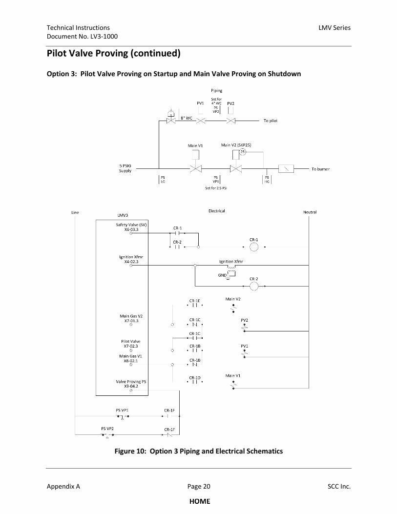
Technical Instructions LMV Series
Document No. LV3-1000
Appendix A Page 20 SCC Inc.
Pilot Valve Proving (continued)
Option 3: Pilot Valve Proving on Startup and Main Valve Proving on Shutdown
Figure 10: Option 3 Piping and Electrical Schematics
LMV Series Technical Instructions
Document No. LV3-1000
SCC Inc. Page 21 Appendix A
Pilot Valve Proving (continued)
Option 3 Sequence of Operation
1. The LMV3 is in standby. All valves are closed and all relay contacts are as shown in the
electrical schematic. Main gas valve V1 terminal X8-02.1 is effectively connected to PV1,
and main gas valve V2 terminal X7-01.3 is effectively connected to PV2.
2. The LMV3 receives a call for heat. The SV terminal (X6-03.3) energizes with the blower,
which has no effect. The LMV3 drives to prepurge position.
3. During prepurge, the valve proving sequence takes place on the pilot valves only. PS-
VP2 (the Pressure Switch Valve Proving between the pilots) is effectively connected to
the valve proving terminal (X9-04.2). The setpoint of PS-VP2 should be set for half of
the inlet pressure to the pilot valves.
4. The LMV3 drives to ignition position. The ignition transformer output (X4-02.3)
energizes, thereby energizing the CR-2 coil, and latching the CR-1 coil from the power
supplied from X6-03.3. The main gas valve V1 terminal (X8-02.1) is connected to main
gas valve V1, and the main gas valve V2 terminal (X7-01.3) is connected to main gas
valve V2. The pilot valve terminal (X7-02.3) is connected to both PV1 and PV2. Also, PS-
VP1 is now connected to the valve proving terminal (X9-04.2).
5. The LMV3 continues to light off and runs as normal, with the CR-1 coil latched in.
6. Upon shutdown, the LMV3 proceeds directly into valve proving on shutdown. The SV
terminal (X6-03.3) is still energized, so the main valves will go through valve proving
using PS-VP1. The setpoint of PS-VP1 should be set for half of the main inlet pressure.
7. After valve proving on shutdown is complete, the SV terminal (X6-03.3) de-energizes
and the CR-1 circuit unlatches.
Option 3 Important Notes
1. Separate pressure switches for the pilot valves and main valves are required.
2. All four valves are tested independently.
3. Valve proving must be done on both startup and shutdown of the boiler.
4. CR-1 should be a force-guided safety relay
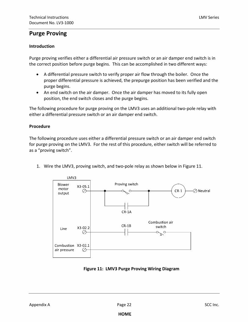
Technical Instructions LMV Series
Document No. LV3-1000
Appendix A Page 22 SCC Inc.
Purge Proving
Introduction
Purge proving verifies either a differential air pressure switch or an air damper end switch is in
the correct position before purge begins. This can be accomplished in two different ways:
• A differential pressure switch to verify proper air flow through the boiler. Once the
proper differential pressure is achieved, the prepurge position has been verified and the
purge begins.
• An end switch on the air damper. Once the air damper has moved to its fully open
position, the end switch closes and the purge begins.
The following procedure for purge proving on the LMV3 uses an additional two-pole relay with
either a differential pressure switch or an air damper end switch.
Procedure
The following procedure uses either a differential pressure switch or an air damper end switch
for purge proving on the LMV3. For the rest of this procedure, either switch will be referred to
as a “proving switch”.
1. Wire the LMV3, proving switch, and two-pole relay as shown below in Figure 11.
Figure 11: LMV3 Purge Proving Wiring Diagram
LMV Series Technical Instructions
Document No. LV3-1000
SCC Inc. Page 23 Appendix A
Purge Proving (continued)
2. Set parameter 211 (fan run-up time) approximately 5 seconds longer than the amount
of time that it takes for the proving switch to close after the fan turns on at the
beginning of phase 22.
Operation
1. In phase 22, the blower motor output (X3-05.1) energizes, powering the common side of
the proving switch.
2. By the end of phase 24, the combustion air pressure input (X3-02.1) must be energized
or the LMV3 will lockout.
3. Once the proving switch closes, relay CR-1 energizes and the two normally-open
contacts close.
4. The contact wired in parallel with the proving switch latches power to relay CR-1 as long
as the blower is on.
5. The other contact wired to line (X3-02.2) completes the circuit to the combustion air
pressure input (X3-02.1), provided that the combustion air switch is also closed. At this
point, the purge proving is complete and the LMV3 will progress to phase 30 (prepurge).
6. After postpurge is completed (phase 78), the blower motor output (X3-05.1) de-
energizes, removing power from relay CR-1 and breaking the latch circuit.
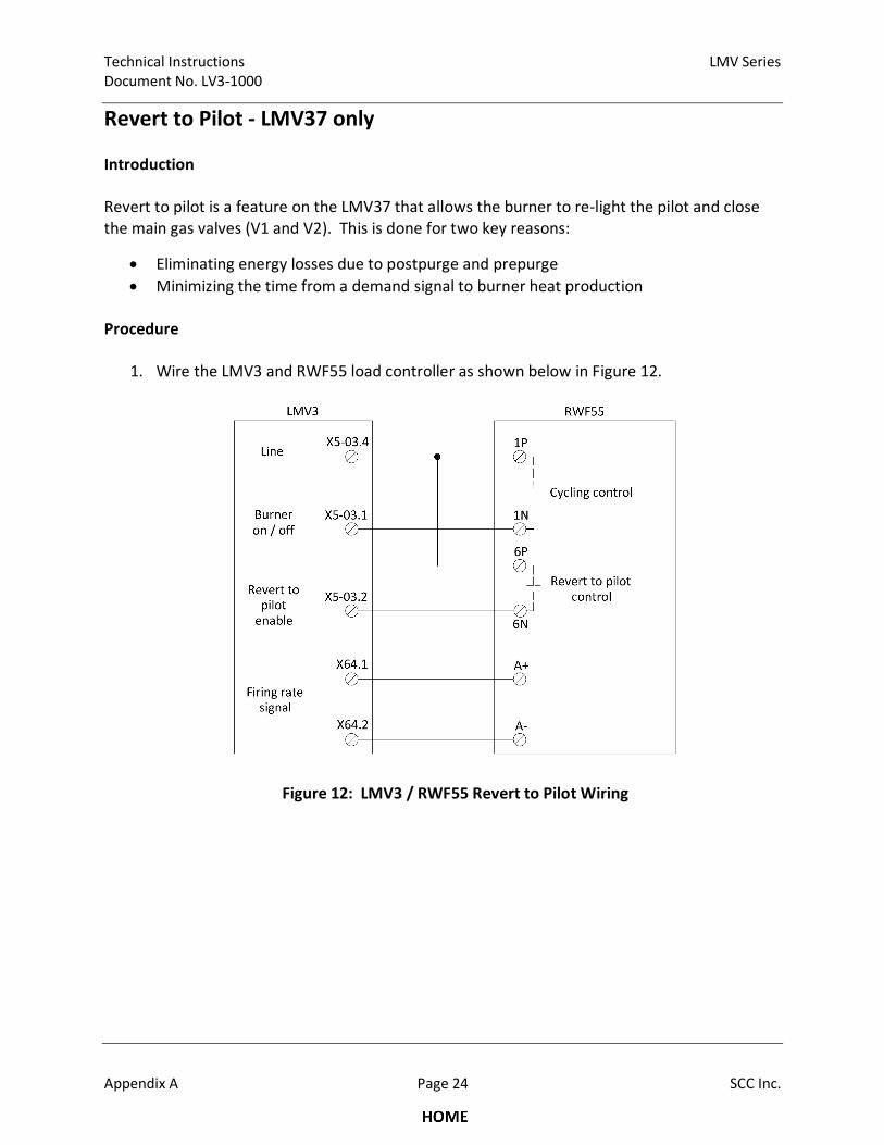
Technical Instructions LMV Series
Document No. LV3-1000
Appendix A Page 24 SCC Inc.
Revert to Pilot - LMV37 only
Introduction
Revert to pilot is a feature on the LMV37 that allows the burner to re-light the pilot and close
the main gas valves (V1 and V2). This is done for two key reasons:
• Eliminating energy losses due to postpurge and prepurge
• Minimizing the time from a demand signal to burner heat production
Procedure
1. Wire the LMV3 and RWF55 load controller as shown below in Figure 12.
Figure 12: LMV3 / RWF55 Revert to Pilot Wiring
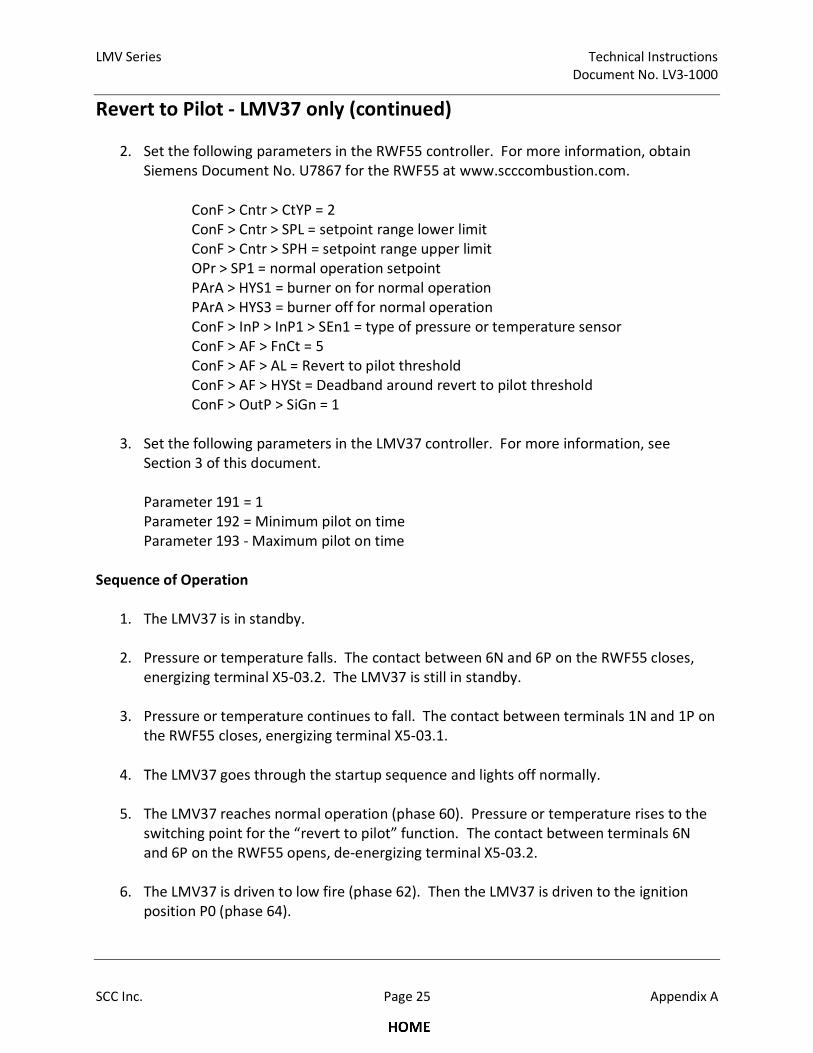
LMV Series Technical Instructions
Document No. LV3-1000
SCC Inc. Page 25 Appendix A
Revert to Pilot - LMV37 only (continued)
2. Set the following parameters in the RWF55 controller. For more information, obtain
Siemens Document No. U7867 for the RWF55 at www.scccombustion.com.
ConF > Cntr > CtYP = 2
ConF > Cntr > SPL = setpoint range lower limit
ConF > Cntr > SPH = setpoint range upper limit
OPr > SP1 = normal operation setpoint
PArA > HYS1 = burner on for normal operation
PArA > HYS3 = burner off for normal operation
ConF > InP > InP1 > SEn1 = type of pressure or temperature sensor
ConF > AF > FnCt = 5
ConF > AF > AL = Revert to pilot threshold
ConF > AF > HYSt = Deadband around revert to pilot threshold
ConF > OutP > SiGn = 1
3. Set the following parameters in the LMV37 controller. For more information, see
Section 3 of this document.
Parameter 191 = 1
Parameter 192 = Minimum pilot on time
Parameter 193 - Maximum pilot on time
Sequence of Operation
1. The LMV37 is in standby.
2. Pressure or temperature falls. The contact between 6N and 6P on the RWF55 closes,
energizing terminal X5-03.2. The LMV37 is still in standby.
3. Pressure or temperature continues to fall. The contact between terminals 1N and 1P on
the RWF55 closes, energizing terminal X5-03.1.
4. The LMV37 goes through the startup sequence and lights off normally.
5. The LMV37 reaches normal operation (phase 60). Pressure or temperature rises to the
switching point for the “revert to pilot” function. The contact between terminals 6N
and 6P on the RWF55 opens, de-energizing terminal X5-03.2.
6. The LMV37 is driven to low fire (phase 62). Then the LMV37 is driven to the ignition
position P0 (phase 64).
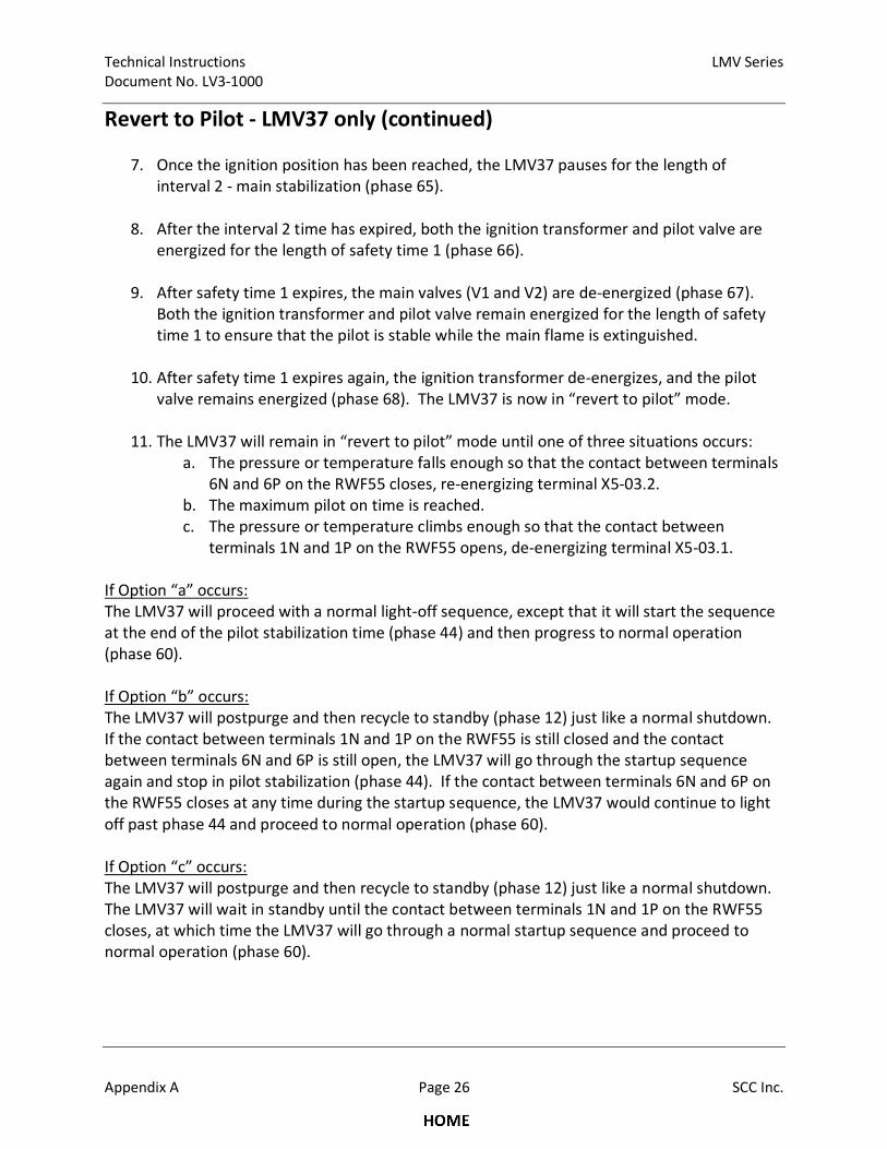
Technical Instructions LMV Series
Document No. LV3-1000
Appendix A Page 26 SCC Inc.
Revert to Pilot - LMV37 only (continued)
7. Once the ignition position has been reached, the LMV37 pauses for the length of
interval 2 - main stabilization (phase 65).
8. After the interval 2 time has expired, both the ignition transformer and pilot valve are
energized for the length of safety time 1 (phase 66).
9. After safety time 1 expires, the main valves (V1 and V2) are de-energized (phase 67).
Both the ignition transformer and pilot valve remain energized for the length of safety
time 1 to ensure that the pilot is stable while the main flame is extinguished.
10. After safety time 1 expires again, the ignition transformer de-energizes, and the pilot
valve remains energized (phase 68). The LMV37 is now in “revert to pilot” mode.
11. The LMV37 will remain in “revert to pilot” mode until one of three situations occurs:
a. The pressure or temperature falls enough so that the contact between terminals
6N and 6P on the RWF55 closes, re-energizing terminal X5-03.2.
b. The maximum pilot on time is reached.
c. The pressure or temperature climbs enough so that the contact between
terminals 1N and 1P on the RWF55 opens, de-energizing terminal X5-03.1.
If Option “a” occurs:
The LMV37 will proceed with a normal light-off sequence, except that it will start the sequence
at the end of the pilot stabilization time (phase 44) and then progress to normal operation
(phase 60).
If Option “b” occurs:
The LMV37 will postpurge and then recycle to standby (phase 12) just like a normal shutdown.
If the contact between terminals 1N and 1P on the RWF55 is still closed and the contact
between terminals 6N and 6P is still open, the LMV37 will go through the startup sequence
again and stop in pilot stabilization (phase 44). If the contact between terminals 6N and 6P on
the RWF55 closes at any time during the startup sequence, the LMV37 would continue to light
off past phase 44 and proceed to normal operation (phase 60).
If Option “c” occurs:
The LMV37 will postpurge and then recycle to standby (phase 12) just like a normal shutdown.
The LMV37 will wait in standby until the contact between terminals 1N and 1P on the RWF55
closes, at which time the LMV37 will go through a normal startup sequence and proceed to
normal operation (phase 60).
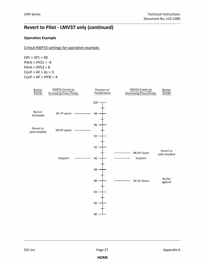
LMV Series Technical Instructions
Document No. LV3-1000
SCC Inc. Page 27 Appendix A
Revert to Pilot - LMV37 only (continued)
Operation Example
Critical RWF55 settings for operation example:
OPr > SP1 = 90
PArA > HYS1 = -4
PArA > HYS3 = 8
ConF > AF > AL = 3
ConF > AF > HYSt = 4
Technical Instructions LMV Series
Document No. LV3-1000
Appendix A Page 28 SCC Inc.
Revert to Pilot - LMV37 only (continued)
Important Notes
1. When the “revert to pilot” function is enabled, float / bump load control via terminal
X5-03 is no longer possible. Input X5-03.3 is no longer used and input X5-03.2 is re-
purposed as the input signal for the “revert to pilot” function.
2. The primary purpose of the maximum pilot on time is so that a burner cannot operate in
the “revert in pilot” mode indefinitely.
3. The secondary purpose of the maximum pilot on time is to protect pilot burners that
may not be rated for continuous operation.
4. The purpose of the minimum pilot on time is to provide a deadband so that the burner
does not constantly revert to pilot and then light off the main burner again repeatedly.
5. Once a “revert to pilot” sequence is initiated, the entire “revert to pilot” sequence must
be followed through, including the minimum pilot on time.
6. It is necessary to have the ignition transformer and the pilot valve energized when the
main valves (V1 and V2) are closed since the main flame extinguishing typically causes a
small pressure pulse that could blow out a pilot that is not supported by an ignition
transformer spark.
7. The flame signal is checked at all times during the “revert to pilot” sequence.

LMV Series Technical Instructions
Document No. LV3-1000
SCC Inc. Page 29 Appendix A
Stack Damper
Introduction
In some applications, a stack damper is used to prevent a draft from coming into the boiler
when the boiler is shut down. However, the stack damper needs to be open during boiler
operation. Typically, it is desired to have the stack damper fully open before the combustion
fan turns on, and to leave the damper open until the combustion fan turns off again. The
following procedure will describe how to wire a stack damper to the LMV3 so that the damper
is open anytime the combustion fan is on.
Procedure
2. Wire the LMV3, RWF5x load controller, and stack damper as shown in Figure 13.
Figure 13: LMV3 Stack Damper Wiring
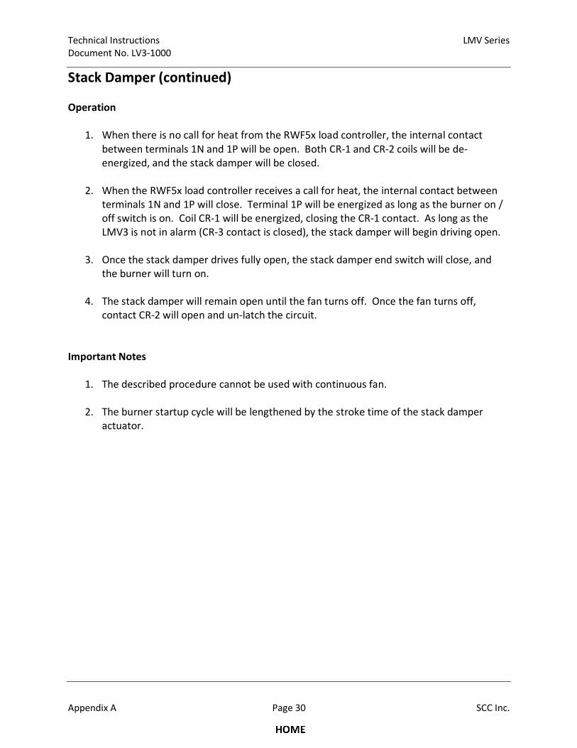
Technical Instructions LMV Series
Document No. LV3-1000
Appendix A Page 30 SCC Inc.
Stack Damper (continued)
Operation
1. When there is no call for heat from the RWF5x load controller, the internal contact
between terminals 1N and 1P will be open. Both CR-1 and CR-2 coils will be de-
energized, and the stack damper will be closed.
2. When the RWF5x load controller receives a call for heat, the internal contact between
terminals 1N and 1P will close. Terminal 1P will be energized as long as the burner on /
off switch is on. Coil CR-1 will be energized, closing the CR-1 contact. As long as the
LMV3 is not in alarm (CR-3 contact is closed), the stack damper will begin driving open.
3. Once the stack damper drives fully open, the stack damper end switch will close, and
the burner will turn on.
4. The stack damper will remain open until the fan turns off. Once the fan turns off,
contact CR-2 will open and un-latch the circuit.
Important Notes
1. The described procedure cannot be used with continuous fan.
2. The burner startup cycle will be lengthened by the stroke time of the stack damper
actuator.

Intentionally Left Blank
Global Siemens Headquarters Siemens AG Berliner Ring 23 76437 Rastatt Germany
SCC, Inc. 1250 Lunt Avenue Elk Grove Village, IL 60007 USA Telephone: 1-224-366-8445
www.scccombustion.com
Printed in USA
© Siemens Industry, Inc. • (05/2015)
Technical Instructions Document No. LV5-1000 July 10, 2015
Daniel Perkins
Rectangle
Daniel Perkins
Typewritten Text
Technical Instructions Document No. LV3-1000 July 19, 2017
Daniel Perkins
Typewritten Text
Daniel Perkins
Typewritten Text
Related Documents