2 This publication is issued to provide outline information only and unless specifically agreed to the contrary by WEALD ELECTRONICS LTD. in writing, is not to form part of any order or contract or be regarded as a representation relating to the products or services concerned. WEALD ELECTRONICS LTD. reserve the right to alter without notice the product design, price or conditions of supply of any product or service. Whilst every effort has been made to ensure that the information contained in this catalogue is accurate, no responsibility can be accepted for any errors or omissions nor for the effects of such errors or omissions. www.wealdelectronics.com

Welcome message from author
This document is posted to help you gain knowledge. Please leave a comment to let me know what you think about it! Share it to your friends and learn new things together.
Transcript

2
This publication is issued to provide outline information only and unless specifically agreed to the contrary by WEALD ELECTRONICS LTD. in writing, is not to form part of any order or contract or be regarded as a representation relating to the products or services concerned.
WEALD ELECTRONICS LTD. reserve the right to alter without notice the product design, price or conditions of supply of any product or service. Whilst every effort has been made to ensure that the information contained in this catalogue is accurate, no responsibility can be accepted
for any errors or omissions nor for the effects of such errors or omissions.
www.wealdelectronics.com
LMF / LMG RANGE CONTENTS
Introduction ………………………………………………………….……………..……………………………………………....……………………………………………….………. 3
How to use LMF / LMG Catalogues .……………………………………………....……………………………………………………….…………………………..………….. 3
LMF Range Basic Information .…………………………………………………………….…….……………………………………………………………………………….……. 4
LMF Range Shell Styles (Aluminium) …………………………………………………………………….………….………………………………….…………………….….... 5
LMF Range Shell Styles (Brass) ….…………………………………………………………………………………………………………………………………………………..... 6
LMF Range Mating Combinations ……………………………………………………………………………………………………………………………………………………. 7
LMF Range Characteristics ….……………………………………………………………………………………………………………………………………………………….….. 8
LMG Range Basic Information ………………………………………………..…………………………………………………………………….…….……………………….….. 9
LMG Range Shell Styles (Aluminium) ………………………………………………………………………………………………….…….…..………………………………. 10
LMG Range Shell Styles (Brass) …………………………………………………………………………………………………………………………………….……………….. 11
LMG Range Mating Combinations ….…………...………………………………………………………………………………………………………………………………… 12
LMG Range Characteristics …….………………...…………………………………………………………………………………………………………………………………… 13
LMF/LMG Connector Ordering Information …………………………………………………………………………………………………………………………………… 14
LMF/LMG Range Connectors ..…………………………………………….. ……………………………………………………………………………….…................. 15-35
LMF/LMG Dimensions and Panel Piercing Details (Aluminium) .………………………………………….…………………………..…………………….…. 36-37
LMF/LMG Dimensions and Panel Piercing Details (Brass) …….…………………………………………………………………………………………………… 38-41
LMF Connector Part Number Index ......................................................................................…………………………………………………………… 42
LMG Connector Part Number Index ..................................................... ……………………………………………………………………………….…......... 43
Product Safety Information……………………………..………………………………….…………………………………………………………….…………...……………… 44 About Weald Electronics Weald Electronics is a leading U.K. manufacturer of electronic and electrical connectors for military and industrial interconnection applications. We offer a wide selection of circular bayonet coupling and screw coupling power connectors, filtered circular connectors and cable connectors in a wide choice of materials and finishes, with specialist ranges suited to the most demanding environments including mining & marine applications. Customers may specify from a wide range of shell sizes, styles, plug and socket contact types and contact arrangements. Double sided bulkhead versions of our connectors are available and thermocouple contacts can be fitted on request.
Product Availability
Weald Electronics connectors are available through our sole worldwide distributors Lane Electronics. Lane Electronics is a franchised distributor for Huber & Suhner, Souriau, ITW McMurdo, Pancon Connectors, Polamco, Glenair, AVX, Neutrik, Nicomatic, Positronic, Amphenol and HellermannTyton. Product types stocked include aerospace, coaxial, RF, audio, MIL-DTL-38999, MIL-DTL-26482, MIL-DTL-5015, DIN 41612, PCB, D type and back shells. This also includes Souriau's MIL-DTL-38999 Elio fibre optic, miniature and naval bronze connector types.
For all enquiries on price and availability, please contact Lane Electronics: Phone: +44 (0)1403 790 661 - Direct line to the sales department. Fax: +44 (0)1403 790 849 Email: [email protected]
3
www.wealdelectronics.com
FOR SALES ENQUIRIES CONTACT F.C. LANE ELECTRONICS LTD TEL: 01403 790661 FAX: 01403 790849 E-mail: [email protected]
FOR TECHNICAL ENQUIRIES CONTACT WEALD ELECTRONICS LTD TEL: 01403 790715 FAX: 01403 790734 E-mail: [email protected]
LMF / LMG RANGE RANGES OF CONNECTORS
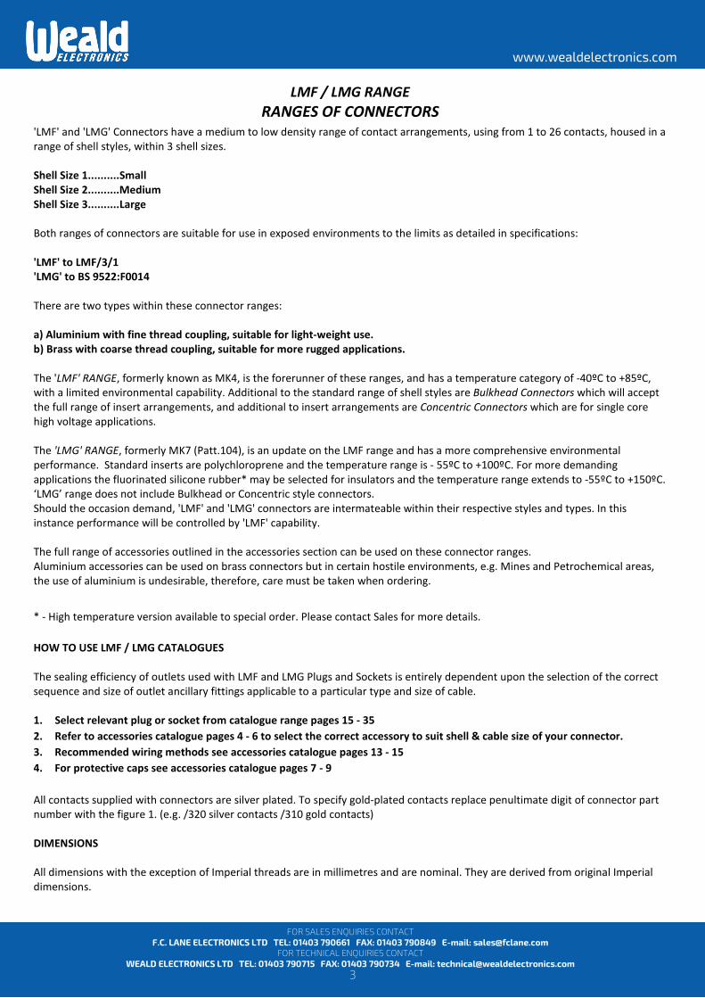
'LMF' and 'LMG' Connectors have a medium to low density range of contact arrangements, using from 1 to 26 contacts, housed in a range of shell styles, within 3 shell sizes. Shell Size 1..........Small Shell Size 2..........Medium Shell Size 3..........Large Both ranges of connectors are suitable for use in exposed environments to the limits as detailed in specifications: 'LMF' to LMF/3/1 'LMG' to BS 9522:F0014 There are two types within these connector ranges: a) Aluminium with fine thread coupling, suitable for light-weight use. b) Brass with coarse thread coupling, suitable for more rugged applications. The 'LMF' RANGE, formerly known as MK4, is the forerunner of these ranges, and has a temperature category of -40ºC to +85ºC, with a limited environmental capability. Additional to the standard range of shell styles are Bulkhead Connectors which will accept the full range of insert arrangements, and additional to insert arrangements are Concentric Connectors which are for single core high voltage applications. The 'LMG' RANGE, formerly MK7 (Patt.104), is an update on the LMF range and has a more comprehensive environmental performance. Standard inserts are polychloroprene and the temperature range is - 55ºC to +100ºC. For more demanding applications the fluorinated silicone rubber* may be selected for insulators and the temperature range extends to -55ºC to +150ºC. ‘LMG’ range does not include Bulkhead or Concentric style connectors. Should the occasion demand, 'LMF' and 'LMG' connectors are intermateable within their respective styles and types. In this instance performance will be controlled by 'LMF' capability. The full range of accessories outlined in the accessories section can be used on these connector ranges. Aluminium accessories can be used on brass connectors but in certain hostile environments, e.g. Mines and Petrochemical areas, the use of aluminium is undesirable, therefore, care must be taken when ordering.
* - High temperature version available to special order. Please contact Sales for more details. HOW TO USE LMF / LMG CATALOGUES The sealing efficiency of outlets used with LMF and LMG Plugs and Sockets is entirely dependent upon the selection of the correct sequence and size of outlet ancillary fittings applicable to a particular type and size of cable. 1. Select relevant plug or socket from catalogue range pages 15 - 35 2. Refer to accessories catalogue pages 4 - 6 to select the correct accessory to suit shell & cable size of your connector. 3. Recommended wiring methods see accessories catalogue pages 13 - 15 4. For protective caps see accessories catalogue pages 7 - 9 All contacts supplied with connectors are silver plated. To specify gold-plated contacts replace penultimate digit of connector part number with the figure 1. (e.g. /320 silver contacts /310 gold contacts) DIMENSIONS All dimensions with the exception of Imperial threads are in millimetres and are nominal. They are derived from original Imperial dimensions.
4
www.wealdelectronics.com
FOR SALES ENQUIRIES CONTACT F.C. LANE ELECTRONICS LTD TEL: 01403 790661 FAX: 01403 790849 E-mail: [email protected]
FOR TECHNICAL ENQUIRIES CONTACT WEALD ELECTRONICS LTD TEL: 01403 790715 FAX: 01403 790734 E-mail: [email protected]
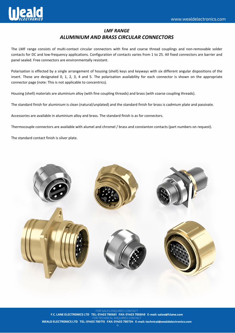
LMF RANGE ALUMINIUM AND BRASS CIRCULAR CONNECTORS
The LMF range consists of multi-contact circular connectors with fine and coarse thread couplings and non-removable solder contacts for DC and low-frequency applications. Configuration of contacts varies from 1 to 25. All fixed connectors are barrier and panel sealed. Free connectors are environmentally resistant. Polarisation is effected by a single arrangement of housing (shell) keys and keyways with six different angular dispositions of the insert. These are designated 0, 1, 2, 3, 4 and 5. The polarisation availability for each connector is shown on the appropriate connector page (note: This is not applicable to concentrics). Housing (shell) materials are aluminium alloy (with fine coupling threads) and brass (with coarse coupling threads). The standard finish for aluminium is clean (natural/unplated) and the standard finish for brass is cadmium plate and passivate. Accessories are available in aluminium alloy and brass. The standard finish is as for connectors. Thermocouple connectors are available with alumel and chromel / brass and constanton contacts (part numbers on request). The standard contact finish is silver plate.
5
www.wealdelectronics.com
FOR SALES ENQUIRIES CONTACT F.C. LANE ELECTRONICS LTD TEL: 01403 790661 FAX: 01403 790849 E-mail: [email protected]
FOR TECHNICAL ENQUIRIES CONTACT WEALD ELECTRONICS LTD TEL: 01403 790715 FAX: 01403 790734 E-mail: [email protected]
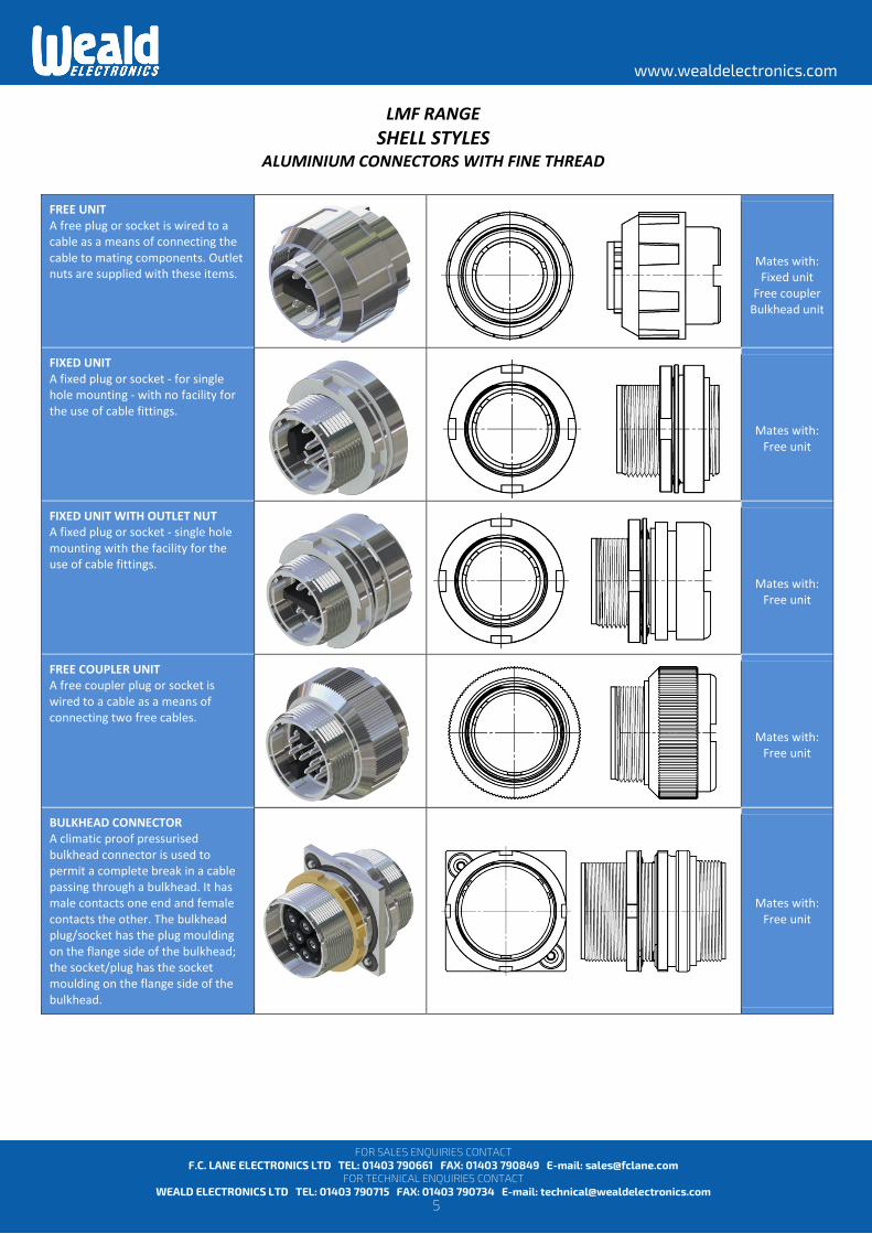
LMF RANGE SHELL STYLES
ALUMINIUM CONNECTORS WITH FINE THREAD
FREE UNIT A free plug or socket is wired to a cable as a means of connecting the cable to mating components. Outlet nuts are supplied with these items.
Mates with: Fixed unit
Free coupler Bulkhead unit
FIXED UNIT A fixed plug or socket - for single hole mounting - with no facility for the use of cable fittings.
Mates with:
Free unit
FIXED UNIT WITH OUTLET NUT A fixed plug or socket - single hole mounting with the facility for the use of cable fittings.
Mates with:
Free unit
FREE COUPLER UNIT A free coupler plug or socket is wired to a cable as a means of connecting two free cables.
Mates with:
Free unit
BULKHEAD CONNECTOR A climatic proof pressurised bulkhead connector is used to permit a complete break in a cable passing through a bulkhead. It has male contacts one end and female contacts the other. The bulkhead plug/socket has the plug moulding on the flange side of the bulkhead; the socket/plug has the socket moulding on the flange side of the bulkhead.
Mates with: Free unit
6
www.wealdelectronics.com
FOR SALES ENQUIRIES CONTACT F.C. LANE ELECTRONICS LTD TEL: 01403 790661 FAX: 01403 790849 E-mail: [email protected]
FOR TECHNICAL ENQUIRIES CONTACT WEALD ELECTRONICS LTD TEL: 01403 790715 FAX: 01403 790734 E-mail: [email protected]
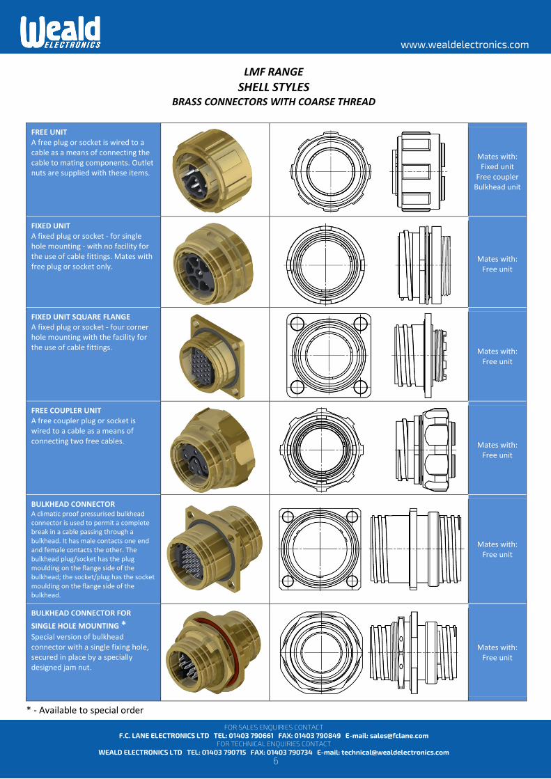
LMF RANGE SHELL STYLES
BRASS CONNECTORS WITH COARSE THREAD
FREE UNIT A free plug or socket is wired to a cable as a means of connecting the cable to mating components. Outlet nuts are supplied with these items.
Mates with: Fixed unit
Free coupler Bulkhead unit
FIXED UNIT A fixed plug or socket - for single hole mounting - with no facility for the use of cable fittings. Mates with free plug or socket only.
Mates with: Free unit
FIXED UNIT SQUARE FLANGE A fixed plug or socket - four corner hole mounting with the facility for the use of cable fittings.
Mates with: Free unit
FREE COUPLER UNIT A free coupler plug or socket is wired to a cable as a means of connecting two free cables.
Mates with: Free unit
BULKHEAD CONNECTOR A climatic proof pressurised bulkhead connector is used to permit a complete break in a cable passing through a bulkhead. It has male contacts one end and female contacts the other. The bulkhead plug/socket has the plug moulding on the flange side of the bulkhead; the socket/plug has the socket moulding on the flange side of the bulkhead.
Mates with: Free unit
BULKHEAD CONNECTOR FOR SINGLE HOLE MOUNTING * Special version of bulkhead connector with a single fixing hole, secured in place by a specially designed jam nut.
Mates with: Free unit
* - Available to special order

7
www.wealdelectronics.com
FOR SALES ENQUIRIES CONTACT F.C. LANE ELECTRONICS LTD TEL: 01403 790661 FAX: 01403 790849 E-mail: [email protected]
FOR TECHNICAL ENQUIRIES CONTACT WEALD ELECTRONICS LTD TEL: 01403 790715 FAX: 01403 790734 E-mail: [email protected]
LMF RANGE MATING COMBINATIONS AND ORIENTATION
All LMF connectors can be supplied with male and female contacts/mouldings and can be mated in combinations as shown above. The complete range of LMF Plugs and Sockets is catalogued on pages 8 to 25, and all units with the same contact arrangement are shown grouped together in order of number of contacts. The diagram above each group shows the plug pin arrangement, the contact coding and moulding characteristics of the mating face of a plug. All coding of sockets is reversed, i.e. a mirror image of the plug coding A feature of LMF plugs and sockets is that the internal moulding carrying the contacts may be located in any one of six radial positions relative to the major keyway in the outer shell (see diagrams at the side of each group, pages 15 to 35). This facility eliminates the possibility of mismating adjacent plugs and sockets of the same contact arrangement. The sixth position is known as 'neutral' (shown in all diagrams as orientation position 0). Unless otherwise stated when ordering, all plugs and sockets will be supplied in the neutral position. Orientated units are identified by replacing the last digit of the part number of the neutral unit with a position number. The last digit for neutral units is always 0. Only orientations of the same suffix number can be mated together. Attention is drawn to the 3 contact 5 amp range of plugs and sockets in which only positions 0 and 5 are available as orientation variations.
Fixed Square Flange
(Brass version only)
Fixed Round Flange
(with and without outlet
nut)
Free coupler
Bulkhead unit
Free unit
8
www.wealdelectronics.com
FOR SALES ENQUIRIES CONTACT F.C. LANE ELECTRONICS LTD TEL: 01403 790661 FAX: 01403 790849 E-mail: [email protected]
FOR TECHNICAL ENQUIRIES CONTACT WEALD ELECTRONICS LTD TEL: 01403 790715 FAX: 01403 790734 E-mail: [email protected]
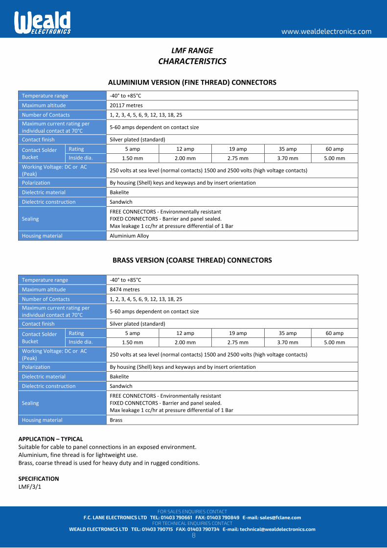
LMF RANGE CHARACTERISTICS
ALUMINIUM VERSION (FINE THREAD) CONNECTORS
BRASS VERSION (COARSE THREAD) CONNECTORS
APPLICATION – TYPICAL Suitable for cable to panel connections in an exposed environment. Aluminium, fine thread is for lightweight use. Brass, coarse thread is used for heavy duty and in rugged conditions. SPECIFICATION LMF/3/1
Temperature range -40° to +85°C
Maximum altitude 20117 metres
Number of Contacts 1, 2, 3, 4, 5, 6, 9, 12, 13, 18, 25 Maximum current rating per individual contact at 70°C 5-60 amps dependent on contact size
Contact finish Silver plated (standard)
Contact Solder Bucket
Rating 5 amp 12 amp 19 amp 35 amp 60 amp Inside dia. 1.50 mm 2.00 mm 2.75 mm 3.70 mm 5.00 mm
Working Voltage: DC or AC (Peak) 250 volts at sea level (normal contacts) 1500 and 2500 volts (high voltage contacts)
Polarization By housing (Shell) keys and keyways and by insert orientation
Dielectric material Bakelite
Dielectric construction Sandwich
Sealing FREE CONNECTORS - Environmentally resistant FIXED CONNECTORS - Barrier and panel sealed. Max leakage 1 cc/hr at pressure differential of 1 Bar
Housing material Aluminium Alloy
Temperature range -40° to +85°C
Maximum altitude 8474 metres
Number of Contacts 1, 2, 3, 4, 5, 6, 9, 12, 13, 18, 25 Maximum current rating per individual contact at 70°C 5-60 amps dependent on contact size
Contact finish Silver plated (standard)
Contact Solder Bucket
Rating 5 amp 12 amp 19 amp 35 amp 60 amp Inside dia. 1.50 mm 2.00 mm 2.75 mm 3.70 mm 5.00 mm
Working Voltage: DC or AC (Peak) 250 volts at sea level (normal contacts) 1500 and 2500 volts (high voltage contacts)
Polarization By housing (Shell) keys and keyways and by insert orientation
Dielectric material Bakelite
Dielectric construction Sandwich
Sealing FREE CONNECTORS - Environmentally resistant FIXED CONNECTORS - Barrier and panel sealed. Max leakage 1 cc/hr at pressure differential of 1 Bar
Housing material Brass

9
www.wealdelectronics.com
FOR SALES ENQUIRIES CONTACT F.C. LANE ELECTRONICS LTD TEL: 01403 790661 FAX: 01403 790849 E-mail: [email protected]
FOR TECHNICAL ENQUIRIES CONTACT WEALD ELECTRONICS LTD TEL: 01403 790715 FAX: 01403 790734 E-mail: [email protected]
LMG RANGE ALUMINIUM AND BRASS CIRCULAR CONNECTORS
The LMG range consists of multi-contact circular connectors with fine and coarse thread couplings and non-removable solder contacts for DC and low-frequency applications. All fixed connectors are barrier and panel sealed. Free connectors are environmentally resistant.
Polarization is effected by a single arrangement of housing (shell) keys and keyways with six different angular dispositions of the insert; these are designated 0, 1, 2, 3, 4 and 5. The polarization availability for each connector is shown on the appropriate connector page.
Housing (shell) materials are aluminium alloy (with fine coupling threads) and brass (with coarse coupling threads.) The standard finish for both materials is drab olive chromate conversion over cadmium plate.
Accessories are available in aluminium alloy and brass. The standard finish for both materials is as for connectors.
The standard contact finish is silver plate.
LMG Range is manufactured in accordance with BS 9522 F0014.
10
www.wealdelectronics.com
FOR SALES ENQUIRIES CONTACT F.C. LANE ELECTRONICS LTD TEL: 01403 790661 FAX: 01403 790849 E-mail: [email protected]
FOR TECHNICAL ENQUIRIES CONTACT WEALD ELECTRONICS LTD TEL: 01403 790715 FAX: 01403 790734 E-mail: [email protected]
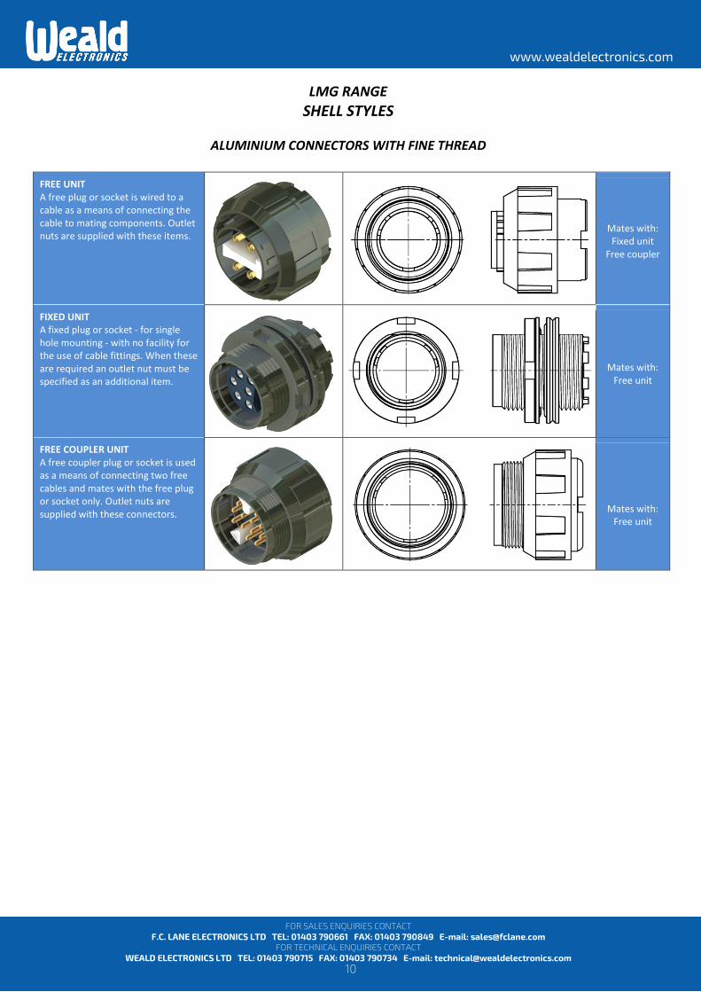
LMG RANGE SHELL STYLES
ALUMINIUM CONNECTORS WITH FINE THREAD
FREE UNIT A free plug or socket is wired to a cable as a means of connecting the cable to mating components. Outlet nuts are supplied with these items.
Mates with: Fixed unit
Free coupler
FIXED UNIT A fixed plug or socket - for single hole mounting - with no facility for the use of cable fittings. When these are required an outlet nut must be specified as an additional item.
Mates with: Free unit
FREE COUPLER UNIT A free coupler plug or socket is used as a means of connecting two free cables and mates with the free plug or socket only. Outlet nuts are supplied with these connectors.
Mates with:
Free unit
11
www.wealdelectronics.com
FOR SALES ENQUIRIES CONTACT F.C. LANE ELECTRONICS LTD TEL: 01403 790661 FAX: 01403 790849 E-mail: [email protected]
FOR TECHNICAL ENQUIRIES CONTACT WEALD ELECTRONICS LTD TEL: 01403 790715 FAX: 01403 790734 E-mail: [email protected]
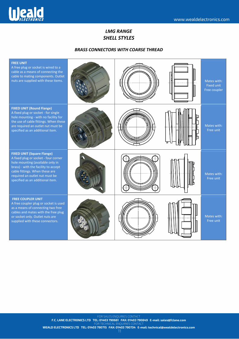
LMG RANGE SHELL STYLES
BRASS CONNECTORS WITH COARSE THREAD
FREE UNIT A free plug or socket is wired to a cable as a means of connecting the cable to mating components. Outlet nuts are supplied with these items.
Mates with: Fixed unit
Free coupler
FIXED UNIT (Round Flange) A fixed plug or socket - for single hole mounting - with no facility for the use of cable fittings. When these are required an outlet nut must be specified as an additional item.
Mates with: Free unit
FIXED UNIT (Square Flange) A fixed plug or socket - four corner hole mounting (available only in brass) - with the facility to accept cable fittings. When these are required an outlet nut must be specified as an additional item.
Mates with:
Free unit
FREE COUPLER UNIT A free coupler plug or socket is used as a means of connecting two free cables and mates with the free plug or socket only. Outlet nuts are supplied with these connectors.
Mates with: Free unit

12
www.wealdelectronics.com
FOR SALES ENQUIRIES CONTACT F.C. LANE ELECTRONICS LTD TEL: 01403 790661 FAX: 01403 790849 E-mail: [email protected]
FOR TECHNICAL ENQUIRIES CONTACT WEALD ELECTRONICS LTD TEL: 01403 790715 FAX: 01403 790734 E-mail: [email protected]
LMG RANGE MATING COMBINATIONS AND ORIENTATION
All LMG connectors can be supplied with male and female contacts/mouldings and can be mated in combinations as shown above. The complete range of LMG Plugs and Sockets is catalogued on pages 16 to 35, and all units with the same contact arrangement are shown grouped together in order of number of contacts. The diagram above each group shows the plug pin arrangement, the contact coding and moulding characteristics of the mating face of a plug. All coding of sockets is reversed, i.e. a mirror image of the plug coding A feature of LMG plugs and sockets is that the internal moulding carrying the contacts may be located in any one of six radial positions relative to the major keyway in the outer shell (see diagrams at the side of each group). This facility eliminates the possibility of mismating adjacent plugs and sockets of the same contact arrangement. The sixth position is known as 'neutral' (shown in all diagrams as orientation position 0). Unless otherwise stated when ordering, all plugs and sockets will be supplied in the neutral position. Orientated units are identified by replacing the last digit of the part number of the neutral unit with a position number. The last digit for neutral units is always 0. Only orientations of the same suffix number can be mated together. Attention is drawn to the 3 contact 5 amp range of plugs and sockets in which only positions 0 and 5 are available as orientation variations.
Fixed Square Flange
(Brass version only)
Fixed Round Flange
Free coupler
Free unit

13
www.wealdelectronics.com
FOR SALES ENQUIRIES CONTACT F.C. LANE ELECTRONICS LTD TEL: 01403 790661 FAX: 01403 790849 E-mail: [email protected]
FOR TECHNICAL ENQUIRIES CONTACT WEALD ELECTRONICS LTD TEL: 01403 790715 FAX: 01403 790734 E-mail: [email protected]
LMG RANGE CHARACTERISTICS
ALUMINIUM VERSION (FINE THREAD) CONNECTORS
BRASS VERSION (COARSE THREAD) CONNECTORS
* - High temperature version available to special order. Please contact Sales for more details. APPLICATION – TYPICAL Suitable for cable to panel connections in an exposed environment. Aluminium, fine thread is for lightweight use. Brass, coarse thread is used for heavy duty and in rugged conditions. SPECIFICATION LMG connectors (formerly MOD pattern 104) are manufactured in accordance with BS 9522 F0014.
Temperature range -55° to +100°C (-55° to +150°C for high temperature version)*
Maximum altitude 20117 metres
Number of Contacts 2, 3, 4, 5, 6, 9, 12, 13, 18, 25 Maximum current rating per individual contact at 70°C 3-60 amps dependent on contact size
Contact finish Silver plated (standard)
Contact Solder Bucket
Rating 3 amp 5 amp 12 amp 19 amp 35 amp 60 amp Inside dia. 1.05 mm 1.50 mm 2.00 mm 2.75 mm 3.70 mm 5.00 mm
Working Voltage: DC or AC (Peak) 500 volts at sea level (normal contacts) 1500 and 2500 volts (high voltage contacts)
Polarization By housing (Shell) keys and keyways and by insert orientation
Dielectric material Polychloroprene (Fluorosilicone rubber - high temperature version)*
Dielectric construction Monobloc
Sealing FREE CONNECTORS - Environmentally resistant FIXED CONNECTORS - Barrier and panel sealed. Max leakage 1 cc/hr at pressure differential of 1 Bar
Housing material Aluminium Alloy
Temperature range -55° to +100°C (-55° to +150°C for high temperature version)*
Maximum altitude 8474 metres
Number of Contacts 2, 3, 4, 5, 6, 9, 12, 13, 18, 25, 37 Maximum current rating per individual contact at 70°C 3-60 amps dependent on contact size
Contact finish Silver plated (standard)
Contact Solder Bucket
Rating 3 amp 5 amp 12 amp 19 amp 35 amp 60 amp Inside dia. 1.05 mm 1.50 mm 2.00 mm 2.75 mm 3.70 mm 5.00 mm
Working Voltage: DC or AC (Peak) 500 volts at sea level (normal contacts) 1500 and 2500 volts (high voltage contacts)
Polarization By housing (Shell) keys and keyways and by insert orientation
Dielectric material Polychloroprene (Fluorosilicone rubber - high temperature version)*
Dielectric construction Monobloc
Sealing FREE CONNECTORS - Environmentally resistant FIXED CONNECTORS - Barrier and panel sealed. Max leakage 1 cc/hr at pressure differential of 1 Bar
Housing material Brass
14
www.wealdelectronics.com
FOR SALES ENQUIRIES CONTACT F.C. LANE ELECTRONICS LTD TEL: 01403 790661 FAX: 01403 790849 E-mail: [email protected]
FOR TECHNICAL ENQUIRIES CONTACT WEALD ELECTRONICS LTD TEL: 01403 790715 FAX: 01403 790734 E-mail: [email protected]
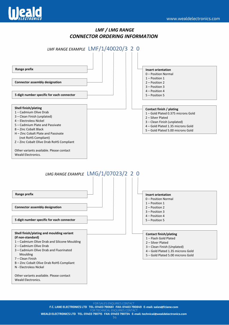
LMF / LMG RANGE CONNECTOR ORDERING INFORMATION
LMF RANGE EXAMPLE LMF/1/40020/3 2 0
LMG RANGE EXAMPLE LMG/1/07023/2 2 0
Connector assembly designation
Contact finish / plating 1 – Gold Plated 0.375 microns Gold 2 – Silver Plated 3 – Clean Finish (unplated) 4 – Gold Plated 1.35 microns Gold 5 – Gold Plated 5.00 microns Gold
Shell finish/plating 1 – Cadmium Olive Drab 3 – Clean Finish (unplated) 4 – Electroless Nickel 5 – Cadmium Plate and Passivate 8 – Zinc Cobalt Black H – Zinc Cobalt Plate and Passivate (not RoHS Compliant) Z – Zinc Cobalt Olive Drab RoHS Compliant Other variants available. Please contact Weald Electronics.
Contact finish/plating 1 – Flash Gold Plated 2 – Silver Plated 3 – Clean Finish (Unplated) 4 – Gold Plated 1.35 microns Gold 5 – Gold Plated 5.00 microns Gold
Shell finish/plating and moulding variant (if non-standard) 1 – Cadmium Olive Drab and Silicone Moulding 2 – Cadmium Olive Drab 3 – Cadmium Olive Drab and Fluorinated Moulding 7 – Clean Finish B – Zinc Cobalt Olive Drab RoHS Compliant N - Electroless Nickel Other variants available. Please contact Weald Electronics.
Range prefix Insert orientation 0 – Position Normal 1 – Position 1 2 – Position 2 3 – Position 3 4 – Position 4 5 – Position 5
Range prefix Insert orientation 0 – Position Normal 1 – Position 1 2 – Position 2 3 – Position 3 4 – Position 4 5 – Position 5
5 digit number specific for each connector
Connector assembly designation
5 digit number specific for each connector
15
www.wealdelectronics.com
FOR SALES ENQUIRIES CONTACT F.C. LANE ELECTRONICS LTD TEL: 01403 790661 FAX: 01403 790849 E-mail: [email protected]
FOR TECHNICAL ENQUIRIES CONTACT WEALD ELECTRONICS LTD TEL: 01403 790715 FAX: 01403 790734 E-mail: [email protected]
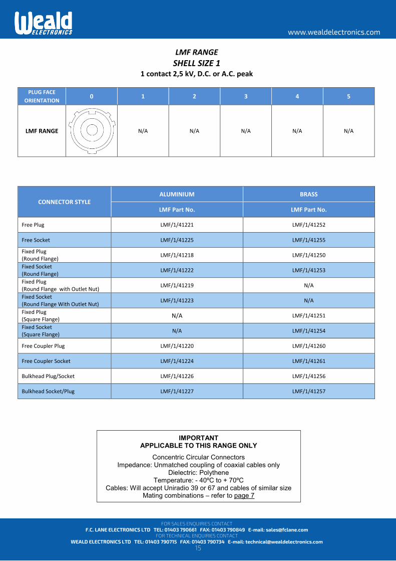
LMF RANGE SHELL SIZE 1
1 contact 2,5 kV, D.C. or A.C. peak
PLUG FACE ORIENTATION 0 1 2 3 4 5
LMF RANGE
N/A N/A N/A N/A N/A
CONNECTOR STYLE ALUMINIUM BRASS
LMF Part No. LMF Part No.
Free Plug LMF/1/41221 LMF/1/41252
Free Socket LMF/1/41225 LMF/1/41255 Fixed Plug (Round Flange) LMF/1/41218 LMF/1/41250 Fixed Socket (Round Flange) LMF/1/41222 LMF/1/41253 Fixed Plug (Round Flange with Outlet Nut) LMF/1/41219 N/A Fixed Socket (Round Flange With Outlet Nut) LMF/1/41223 N/A Fixed Plug (Square Flange) N/A LMF/1/41251 Fixed Socket (Square Flange) N/A LMF/1/41254
Free Coupler Plug LMF/1/41220 LMF/1/41260
Free Coupler Socket LMF/1/41224 LMF/1/41261
Bulkhead Plug/Socket LMF/1/41226 LMF/1/41256
Bulkhead Socket/Plug LMF/1/41227 LMF/1/41257
IMPORTANT APPLICABLE TO THIS RANGE ONLY
Concentric Circular Connectors Impedance: Unmatched coupling of coaxial cables only
Dielectric: Polythene Temperature: - 40ºC to + 70ºC
Cables: Will accept Uniradio 39 or 67 and cables of similar size Mating combinations – refer to page 7

16
www.wealdelectronics.com
FOR SALES ENQUIRIES CONTACT F.C. LANE ELECTRONICS LTD TEL: 01403 790661 FAX: 01403 790849 E-mail: [email protected]
FOR TECHNICAL ENQUIRIES CONTACT WEALD ELECTRONICS LTD TEL: 01403 790715 FAX: 01403 790734 E-mail: [email protected]
LMF / LMG RANGE SHELL SIZE 1
2 contacts 19 amps
PLUG FACE ORIENTATION 0 1 2 3 4 5
LMF RANGE 250 volts D.C. or A.C. peak
LMG RANGE 500 volts D.C. or A.C. peak
CONNECTOR STYLE ALUMINIUM BRASS
LMF Part No. LMG Part No. LMF Part No. LMG Part No.
Free Plug LMF/1/40020/320 LMG/1/07020/220 LMF/1/40220/520 LMG/1/07220/220
Free Socket LMF/1/40000/320 LMG/1/07000/220 LMF/1/40200/520 LMG/1/07200/220
Fixed Plug (Round Flange) LMF/1/40060/320 LMG/1/07060/220 LMF/1/40260/520 LMG/1/07340/220
Fixed Socket (Round Flange) LMF/1/40040/320 LMG/1/07040/220 LMF/1/40240/520 LMG/1/07320/220
Fixed Plug (Round Flange with Outlet Nut) LMF/1/40140/320 N/A N/A N/A
Fixed Socket (Round Flange With Outlet Nut) LMF/1/40120/320 N/A N/A N/A
Fixed Plug (Square Flange) N/A N/A LMF/1/40340/520 LMG/1/07260/220
Fixed Socket (Square Flange) N/A N/A LMF/1/40320/520 LMG/1/07240/220
Free Coupler Plug LMF/1/40100/320 LMG/1/07100/220 LMF/1/40300/520 LMG/1/07300/220
Free Coupler Socket LMF/1/40080/320 LMG/1/07080/220 LMF/1/40280/520 LMG/1/07280/220
Bulkhead Plug/Socket LMF/1/30180/320 N/A LMF/1/40380/520 N/A
Bulkhead Socket/Plug LMF/1/40160/320 N/A LMF/1/40360/520 N/A
IMPORTANT
Only shell size 1 codes a & b accessories may be used with these connectors. Mating combinations – refer to page 7 (for LMF) or page 12 (for LMG).
To specify orientation versions replace last digit with digit of relevant position number, e.g. LMF/1/40020/325 = ORIENTATION POSITION 5

17
www.wealdelectronics.com
FOR SALES ENQUIRIES CONTACT F.C. LANE ELECTRONICS LTD TEL: 01403 790661 FAX: 01403 790849 E-mail: [email protected]
FOR TECHNICAL ENQUIRIES CONTACT WEALD ELECTRONICS LTD TEL: 01403 790715 FAX: 01403 790734 E-mail: [email protected]
LMF / LMG RANGE SHELL SIZE 2
2 contacts 35 amps
PLUG FACE ORIENTATION 0 1 2 3 4 5
LMF RANGE 250 volts D.C. or A.C. peak
LMG RANGE 500 volts D.C. or A.C. peak
CONNECTOR STYLE ALUMINIUM BRASS
LMF Part No. LMG Part No. LMF Part No. LMG Part No.
Free Plug LMF/1/40024/320 LMG/1/07024/220 LMF/1/40224/520 LMG/1/07224/220
Free Socket LMF/1/40004/320 LMG/1/07004/220 LMF/1/40204/520 LMG/1/07204/220
Fixed Plug (Round Flange) LMF/1/40064/320 LMG/1/07064/220 LMF/1/40264/520 LMG/1/07344/220
Fixed Socket (Round Flange) LMF/1/40044/320 LMG/1/07044/220 LMF/1/40244/520 LMG/1/07324/220
Fixed Plug (Round Flange with Outlet Nut) LMF/1/40144/320 N/A N/A N/A
Fixed Socket (Round Flange With Outlet Nut) LMF/1/40124/320 N/A N/A N/A
Fixed Plug (Square Flange) N/A N/A LMF/1/40344/520 LMG/1/07264/220
Fixed Socket (Square Flange) N/A N/A LMF/1/40324/520 LMG/1/07244/220
Free Coupler Plug LMF/1/40104/320 LMG/1/07104/220 LMF/1/40304/520 LMG/1/07304/220
Free Coupler Socket LMF/1/40084/320 LMG/1/07084/220 LMF/1/40284/520 LMG/1/07284/220
Bulkhead Plug/Socket N/A N/A N/A N/A
Bulkhead Socket/Plug N/A N/A N/A N/A
IMPORTANT
Only shell size 2 codes c, d, e & f accessories may be used with these connectors. Mating combinations – refer to page 7 (for LMF) or page 12 (for LMG).
To specify orientation versions replace last digit with digit of relevant position number, e.g. LMF/1/40024/325 = ORIENTATION POSITION 5
18
www.wealdelectronics.com
FOR SALES ENQUIRIES CONTACT F.C. LANE ELECTRONICS LTD TEL: 01403 790661 FAX: 01403 790849 E-mail: [email protected]
FOR TECHNICAL ENQUIRIES CONTACT WEALD ELECTRONICS LTD TEL: 01403 790715 FAX: 01403 790734 E-mail: [email protected]
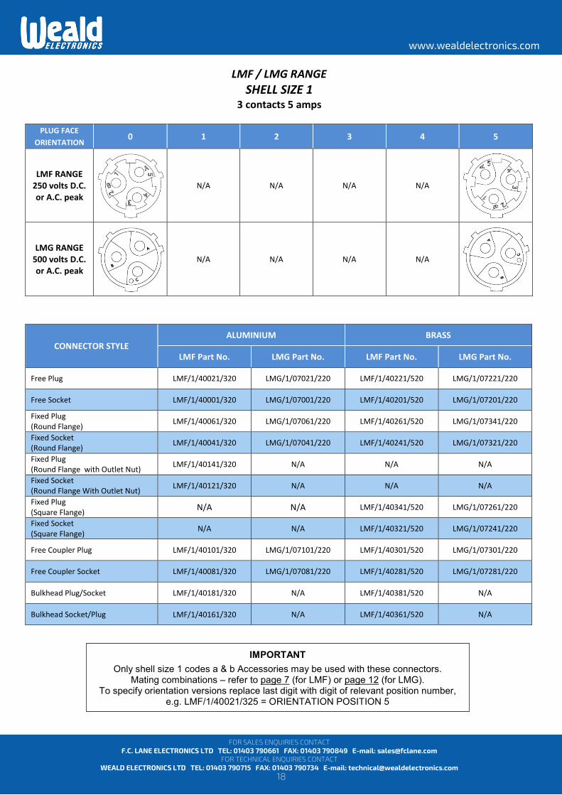
LMF / LMG RANGE SHELL SIZE 1
3 contacts 5 amps
PLUG FACE ORIENTATION 0 1 2 3 4 5
LMF RANGE 250 volts D.C. or A.C. peak
N/A N/A N/A N/A
LMG RANGE 500 volts D.C. or A.C. peak
N/A N/A N/A N/A
CONNECTOR STYLE ALUMINIUM BRASS
LMF Part No. LMG Part No. LMF Part No. LMG Part No.
Free Plug LMF/1/40021/320 LMG/1/07021/220 LMF/1/40221/520 LMG/1/07221/220
Free Socket LMF/1/40001/320 LMG/1/07001/220 LMF/1/40201/520 LMG/1/07201/220
Fixed Plug (Round Flange) LMF/1/40061/320 LMG/1/07061/220 LMF/1/40261/520 LMG/1/07341/220
Fixed Socket (Round Flange) LMF/1/40041/320 LMG/1/07041/220 LMF/1/40241/520 LMG/1/07321/220
Fixed Plug (Round Flange with Outlet Nut) LMF/1/40141/320 N/A N/A N/A
Fixed Socket (Round Flange With Outlet Nut) LMF/1/40121/320 N/A N/A N/A
Fixed Plug (Square Flange) N/A N/A LMF/1/40341/520 LMG/1/07261/220
Fixed Socket (Square Flange) N/A N/A LMF/1/40321/520 LMG/1/07241/220
Free Coupler Plug LMF/1/40101/320 LMG/1/07101/220 LMF/1/40301/520 LMG/1/07301/220
Free Coupler Socket LMF/1/40081/320 LMG/1/07081/220 LMF/1/40281/520 LMG/1/07281/220
Bulkhead Plug/Socket LMF/1/40181/320 N/A LMF/1/40381/520 N/A
Bulkhead Socket/Plug LMF/1/40161/320 N/A LMF/1/40361/520 N/A
IMPORTANT
Only shell size 1 codes a & b Accessories may be used with these connectors. Mating combinations – refer to page 7 (for LMF) or page 12 (for LMG).
To specify orientation versions replace last digit with digit of relevant position number, e.g. LMF/1/40021/325 = ORIENTATION POSITION 5

19
www.wealdelectronics.com
FOR SALES ENQUIRIES CONTACT F.C. LANE ELECTRONICS LTD TEL: 01403 790661 FAX: 01403 790849 E-mail: [email protected]
FOR TECHNICAL ENQUIRIES CONTACT WEALD ELECTRONICS LTD TEL: 01403 790715 FAX: 01403 790734 E-mail: [email protected]
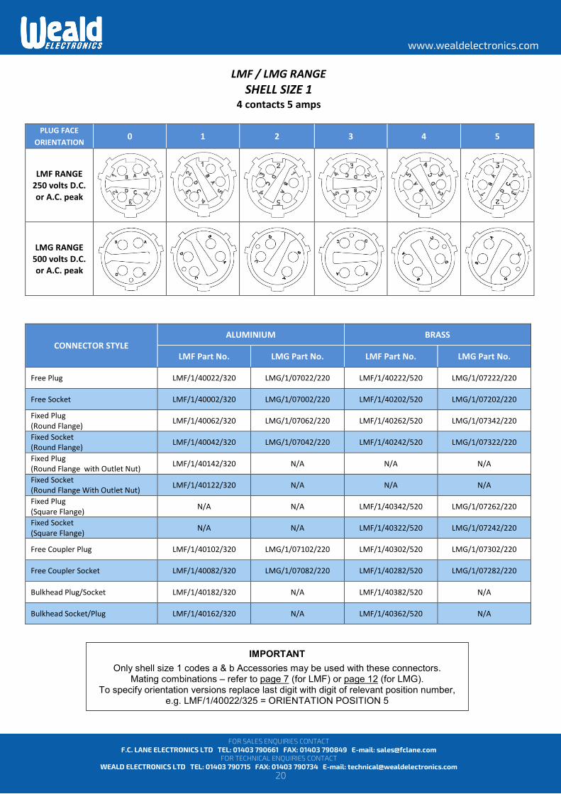
LMF / LMG RANGE SHELL SIZE 2
3 contacts 19 amps
PLUG FACE ORIENTATION 0 1 2 3 4 5
LMF RANGE 1.5 kV D.C. or
A.C. peak
LMG RANGE 1.5 kV D.C. or
A.C. peak
CONNECTOR STYLE ALUMINIUM BRASS
LMF Part No. LMG Part No. LMF Part No. LMG Part No.
Free Plug LMF/1/40025/320 LMG/1/07025/220 LMF/1/40225/520 LMG/1/07225/220
Free Socket LMF/1/40005/320 LMG/1/07005/220 LMF/1/40205/520 LMG/1/07205/220
Fixed Plug (Round Flange) LMF/1/40065/320 LMG/1/07065/220 LMF/1/40265/520 LMG/1/07345/220
Fixed Socket (Round Flange) LMF/1/40045/320 LMG/1/07045/220 LMF/1/40245/520 LMG/1/07325/220
Fixed Plug (Round Flange with Outlet Nut) LMF/1/40145/320 N/A N/A N/A
Fixed Socket (Round Flange With Outlet Nut) LMF/1/40125/320 N/A N/A N/A
Fixed Plug (Square Flange) N/A N/A LMF/1/40345/520 LMG/1/07265/220
Fixed Socket (Square Flange) N/A N/A LMF/1/40325/520 LMG/1/07245/220
Free Coupler Plug LMF/1/40105/320 LMG/1/07105/220 LMF/1/40305/520 LMG/1/07305/220
Free Coupler Socket LMF/1/40085/320 LMG/1/07085/220 LMF/1/40285/520 LMG/1/07285/220
Bulkhead Plug/Socket N/A N/A N/A N/A
Bulkhead Socket/Plug N/A N/A N/A N/A
IMPORTANT
Only shell size 2 codes c, d, e & f accessories may be used with these connectors. Mating combinations – refer to page 7 (for LMF) or page 12 (for LMG).
To specify orientation versions replace last digit with digit of relevant position number, e.g. LMF/1/40025/325 = ORIENTATION POSITION 5
20
www.wealdelectronics.com
FOR SALES ENQUIRIES CONTACT F.C. LANE ELECTRONICS LTD TEL: 01403 790661 FAX: 01403 790849 E-mail: [email protected]
FOR TECHNICAL ENQUIRIES CONTACT WEALD ELECTRONICS LTD TEL: 01403 790715 FAX: 01403 790734 E-mail: [email protected]
LMF / LMG RANGE SHELL SIZE 1
4 contacts 5 amps
PLUG FACE ORIENTATION 0 1 2 3 4 5
LMF RANGE 250 volts D.C. or A.C. peak
LMG RANGE 500 volts D.C. or A.C. peak
CONNECTOR STYLE ALUMINIUM BRASS
LMF Part No. LMG Part No. LMF Part No. LMG Part No.
Free Plug LMF/1/40022/320 LMG/1/07022/220 LMF/1/40222/520 LMG/1/07222/220
Free Socket LMF/1/40002/320 LMG/1/07002/220 LMF/1/40202/520 LMG/1/07202/220
Fixed Plug (Round Flange) LMF/1/40062/320 LMG/1/07062/220 LMF/1/40262/520 LMG/1/07342/220
Fixed Socket (Round Flange) LMF/1/40042/320 LMG/1/07042/220 LMF/1/40242/520 LMG/1/07322/220
Fixed Plug (Round Flange with Outlet Nut) LMF/1/40142/320 N/A N/A N/A
Fixed Socket (Round Flange With Outlet Nut) LMF/1/40122/320 N/A N/A N/A
Fixed Plug (Square Flange) N/A N/A LMF/1/40342/520 LMG/1/07262/220
Fixed Socket (Square Flange) N/A N/A LMF/1/40322/520 LMG/1/07242/220
Free Coupler Plug LMF/1/40102/320 LMG/1/07102/220 LMF/1/40302/520 LMG/1/07302/220
Free Coupler Socket LMF/1/40082/320 LMG/1/07082/220 LMF/1/40282/520 LMG/1/07282/220
Bulkhead Plug/Socket LMF/1/40182/320 N/A LMF/1/40382/520 N/A
Bulkhead Socket/Plug LMF/1/40162/320 N/A LMF/1/40362/520 N/A
IMPORTANT
Only shell size 1 codes a & b Accessories may be used with these connectors. Mating combinations – refer to page 7 (for LMF) or page 12 (for LMG).
To specify orientation versions replace last digit with digit of relevant position number, e.g. LMF/1/40022/325 = ORIENTATION POSITION 5
21
www.wealdelectronics.com
FOR SALES ENQUIRIES CONTACT F.C. LANE ELECTRONICS LTD TEL: 01403 790661 FAX: 01403 790849 E-mail: [email protected]
FOR TECHNICAL ENQUIRIES CONTACT WEALD ELECTRONICS LTD TEL: 01403 790715 FAX: 01403 790734 E-mail: [email protected]
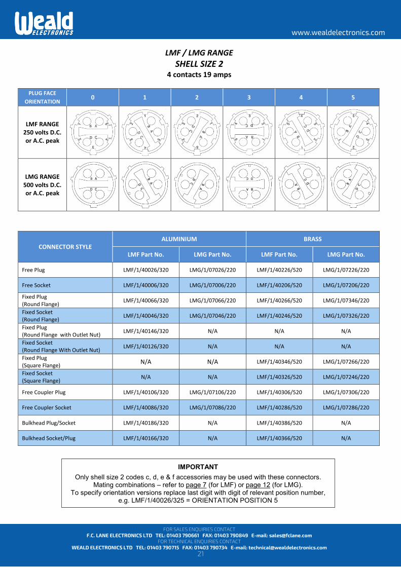
LMF / LMG RANGE SHELL SIZE 2
4 contacts 19 amps
PLUG FACE ORIENTATION 0 1 2 3 4 5
LMF RANGE 250 volts D.C. or A.C. peak
LMG RANGE 500 volts D.C. or A.C. peak
CONNECTOR STYLE ALUMINIUM BRASS
LMF Part No. LMG Part No. LMF Part No. LMG Part No.
Free Plug LMF/1/40026/320 LMG/1/07026/220 LMF/1/40226/520 LMG/1/07226/220
Free Socket LMF/1/40006/320 LMG/1/07006/220 LMF/1/40206/520 LMG/1/07206/220
Fixed Plug (Round Flange) LMF/1/40066/320 LMG/1/07066/220 LMF/1/40266/520 LMG/1/07346/220
Fixed Socket (Round Flange) LMF/1/40046/320 LMG/1/07046/220 LMF/1/40246/520 LMG/1/07326/220
Fixed Plug (Round Flange with Outlet Nut) LMF/1/40146/320 N/A N/A N/A
Fixed Socket (Round Flange With Outlet Nut) LMF/1/40126/320 N/A N/A N/A
Fixed Plug (Square Flange) N/A N/A LMF/1/40346/520 LMG/1/07266/220
Fixed Socket (Square Flange) N/A N/A LMF/1/40326/520 LMG/1/07246/220
Free Coupler Plug LMF/1/40106/320 LMG/1/07106/220 LMF/1/40306/520 LMG/1/07306/220
Free Coupler Socket LMF/1/40086/320 LMG/1/07086/220 LMF/1/40286/520 LMG/1/07286/220
Bulkhead Plug/Socket LMF/1/40186/320 N/A LMF/1/40386/520 N/A
Bulkhead Socket/Plug LMF/1/40166/320 N/A LMF/1/40366/520 N/A
IMPORTANT
Only shell size 2 codes c, d, e & f accessories may be used with these connectors. Mating combinations – refer to page 7 (for LMF) or page 12 (for LMG).
To specify orientation versions replace last digit with digit of relevant position number, e.g. LMF/1/40026/325 = ORIENTATION POSITION 5

22
www.wealdelectronics.com
FOR SALES ENQUIRIES CONTACT F.C. LANE ELECTRONICS LTD TEL: 01403 790661 FAX: 01403 790849 E-mail: [email protected]
FOR TECHNICAL ENQUIRIES CONTACT WEALD ELECTRONICS LTD TEL: 01403 790715 FAX: 01403 790734 E-mail: [email protected]
LMF / LMG RANGE SHELL SIZE 3
4 contacts 3 contacts 60 amps, 1 contact 19 amps
PLUG FACE
ORIENTATION 0 1 2 3 4 5
LMF RANGE 250 volts D.C. or A.C. peak
LMG RANGE 500 volts D.C. or A.C. peak
CONNECTOR STYLE ALUMINIUM BRASS
LMF Part No. LMG Part No. LMF Part No. LMG Part No.
Free Plug LMF/1/40030/320 LMG/1/07030/220 LMF/1/40230/520 LMG/1/07230/220
Free Socket LMF/1/40010/320 LMG/1/07010/220 LMF/1/40210/520 LMG/1/07210/220
Fixed Plug (Round Flange) LMF/1/40070/320 LMG/1/07070/220 LMF/1/40270/520 LMG/1/07350/220
Fixed Socket (Round Flange) LMF/1/40050/320 LMG/1/07050/220 LMF/1/40250/520 LMG/1/07330/220
Fixed Plug (Round Flange with Outlet Nut) LMF/1/40150/320 N/A N/A N/A
Fixed Socket (Round Flange With Outlet Nut) LMF/1/40130/320 N/A N/A N/A
Fixed Plug (Square Flange) N/A N/A LMF/1/40350/520 LMG/1/07270/220
Fixed Socket (Square Flange) N/A N/A LMF/1/40330/520 LMG/1/07250/220
Free Coupler Plug LMF/1/40110/320 LMG/1/07110/220 LMF/1/40310/520 LMG/1/07310/220
Free Coupler Socket LMF/1/40090/320 LMG/1/07090/220 LMF/1/40290/520 LMG/1/07290/220
Bulkhead Plug/Socket N/A N/A N/A N/A
Bulkhead Socket/Plug N/A N/A N/A N/A
IMPORTANT
Only shell size 3 codes g, h & i accessories may be used with these connectors. Mating combinations – refer to page 7 (for LMF) or page 12 (for LMG).
To specify orientation versions replace last digit with digit of relevant position number, e.g. LMF/1/40030/325 = ORIENTATION POSITION 5
23
www.wealdelectronics.com
FOR SALES ENQUIRIES CONTACT F.C. LANE ELECTRONICS LTD TEL: 01403 790661 FAX: 01403 790849 E-mail: [email protected]
FOR TECHNICAL ENQUIRIES CONTACT WEALD ELECTRONICS LTD TEL: 01403 790715 FAX: 01403 790734 E-mail: [email protected]
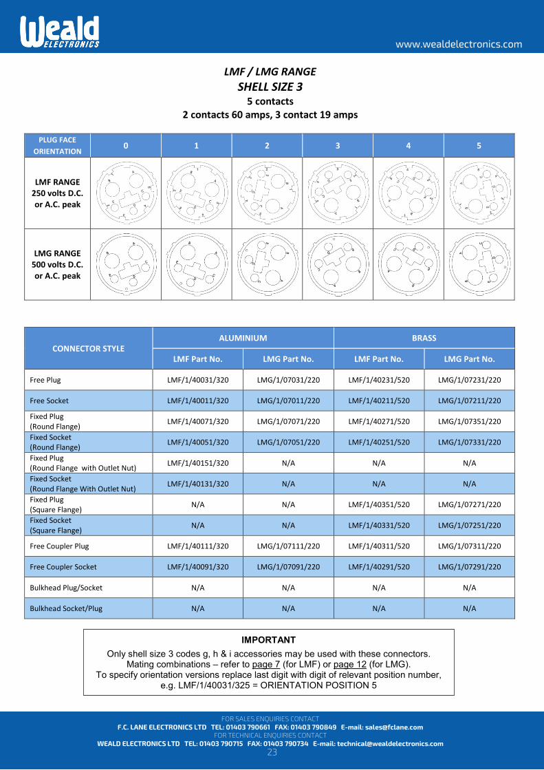
LMF / LMG RANGE SHELL SIZE 3
5 contacts 2 contacts 60 amps, 3 contact 19 amps
PLUG FACE
ORIENTATION 0 1 2 3 4 5
LMF RANGE 250 volts D.C. or A.C. peak
LMG RANGE 500 volts D.C. or A.C. peak
CONNECTOR STYLE ALUMINIUM BRASS
LMF Part No. LMG Part No. LMF Part No. LMG Part No.
Free Plug LMF/1/40031/320 LMG/1/07031/220 LMF/1/40231/520 LMG/1/07231/220
Free Socket LMF/1/40011/320 LMG/1/07011/220 LMF/1/40211/520 LMG/1/07211/220
Fixed Plug (Round Flange) LMF/1/40071/320 LMG/1/07071/220 LMF/1/40271/520 LMG/1/07351/220
Fixed Socket (Round Flange) LMF/1/40051/320 LMG/1/07051/220 LMF/1/40251/520 LMG/1/07331/220
Fixed Plug (Round Flange with Outlet Nut) LMF/1/40151/320 N/A N/A N/A
Fixed Socket (Round Flange With Outlet Nut) LMF/1/40131/320 N/A N/A N/A
Fixed Plug (Square Flange) N/A N/A LMF/1/40351/520 LMG/1/07271/220
Fixed Socket (Square Flange) N/A N/A LMF/1/40331/520 LMG/1/07251/220
Free Coupler Plug LMF/1/40111/320 LMG/1/07111/220 LMF/1/40311/520 LMG/1/07311/220
Free Coupler Socket LMF/1/40091/320 LMG/1/07091/220 LMF/1/40291/520 LMG/1/07291/220
Bulkhead Plug/Socket N/A N/A N/A N/A
Bulkhead Socket/Plug N/A N/A N/A N/A
IMPORTANT
Only shell size 3 codes g, h & i accessories may be used with these connectors. Mating combinations – refer to page 7 (for LMF) or page 12 (for LMG).
To specify orientation versions replace last digit with digit of relevant position number, e.g. LMF/1/40031/325 = ORIENTATION POSITION 5
24
www.wealdelectronics.com
FOR SALES ENQUIRIES CONTACT F.C. LANE ELECTRONICS LTD TEL: 01403 790661 FAX: 01403 790849 E-mail: [email protected]
FOR TECHNICAL ENQUIRIES CONTACT WEALD ELECTRONICS LTD TEL: 01403 790715 FAX: 01403 790734 E-mail: [email protected]
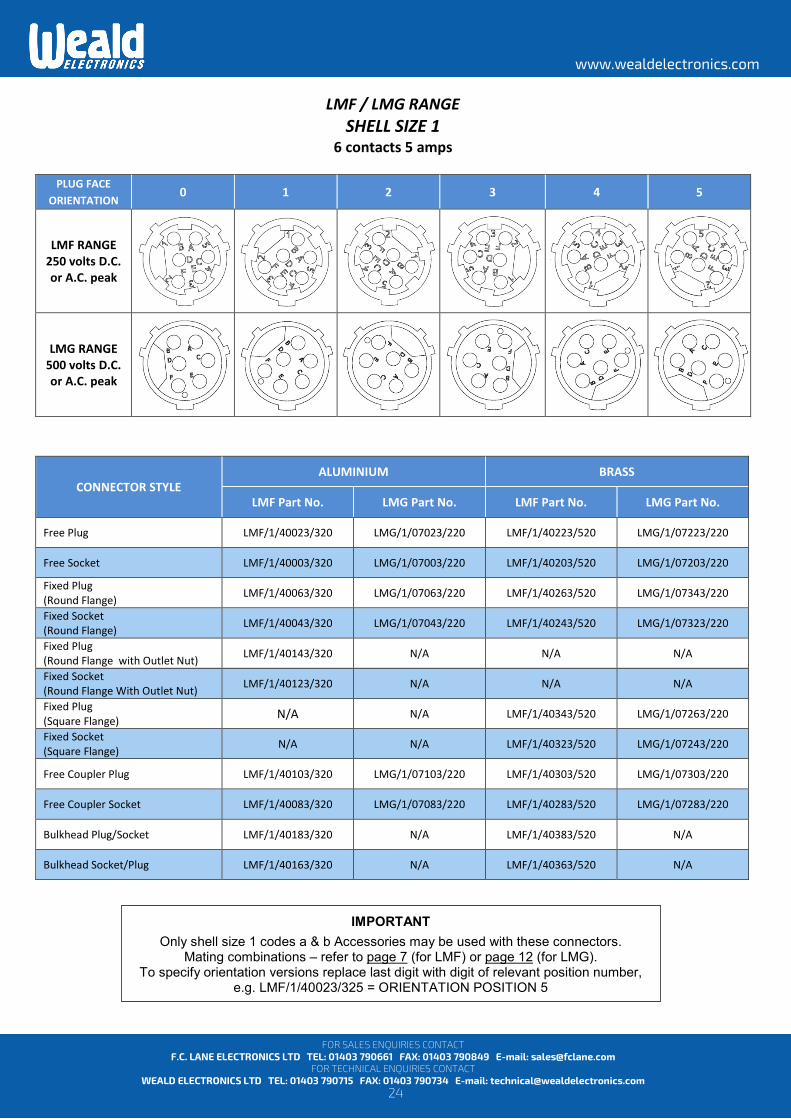
LMF / LMG RANGE SHELL SIZE 1
6 contacts 5 amps
PLUG FACE ORIENTATION 0 1 2 3 4 5
LMF RANGE 250 volts D.C. or A.C. peak
LMG RANGE 500 volts D.C. or A.C. peak
CONNECTOR STYLE ALUMINIUM BRASS
LMF Part No. LMG Part No. LMF Part No. LMG Part No.
Free Plug LMF/1/40023/320 LMG/1/07023/220 LMF/1/40223/520 LMG/1/07223/220
Free Socket LMF/1/40003/320 LMG/1/07003/220 LMF/1/40203/520 LMG/1/07203/220
Fixed Plug (Round Flange) LMF/1/40063/320 LMG/1/07063/220 LMF/1/40263/520 LMG/1/07343/220
Fixed Socket (Round Flange) LMF/1/40043/320 LMG/1/07043/220 LMF/1/40243/520 LMG/1/07323/220
Fixed Plug (Round Flange with Outlet Nut) LMF/1/40143/320 N/A N/A N/A
Fixed Socket (Round Flange With Outlet Nut) LMF/1/40123/320 N/A N/A N/A
Fixed Plug (Square Flange) N/A N/A LMF/1/40343/520 LMG/1/07263/220
Fixed Socket (Square Flange) N/A N/A LMF/1/40323/520 LMG/1/07243/220
Free Coupler Plug LMF/1/40103/320 LMG/1/07103/220 LMF/1/40303/520 LMG/1/07303/220
Free Coupler Socket LMF/1/40083/320 LMG/1/07083/220 LMF/1/40283/520 LMG/1/07283/220
Bulkhead Plug/Socket LMF/1/40183/320 N/A LMF/1/40383/520 N/A
Bulkhead Socket/Plug LMF/1/40163/320 N/A LMF/1/40363/520 N/A
IMPORTANT
Only shell size 1 codes a & b Accessories may be used with these connectors. Mating combinations – refer to page 7 (for LMF) or page 12 (for LMG).
To specify orientation versions replace last digit with digit of relevant position number, e.g. LMF/1/40023/325 = ORIENTATION POSITION 5
25
www.wealdelectronics.com
FOR SALES ENQUIRIES CONTACT F.C. LANE ELECTRONICS LTD TEL: 01403 790661 FAX: 01403 790849 E-mail: [email protected]
FOR TECHNICAL ENQUIRIES CONTACT WEALD ELECTRONICS LTD TEL: 01403 790715 FAX: 01403 790734 E-mail: [email protected]
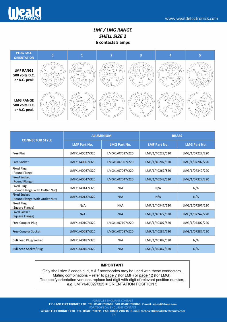
LMF / LMG RANGE SHELL SIZE 2
6 contacts 5 amps
PLUG FACE ORIENTATION 0 1 2 3 4 5
LMF RANGE 500 volts D.C. or A.C. peak
LMG RANGE 500 volts D.C. or A.C. peak
CONNECTOR STYLE ALUMINIUM BRASS
LMF Part No. LMG Part No. LMF Part No. LMG Part No.
Free Plug LMF/1/40027/320 LMG/1/07027/220 LMF/1/40227/520 LMG/1/07227/220
Free Socket LMF/1/40007/320 LMG/1/07007/220 LMF/1/40207/520 LMG/1/07207/220
Fixed Plug (Round Flange) LMF/1/40067/320 LMG/1/07067/220 LMF/1/40267/520 LMG/1/07347/220
Fixed Socket (Round Flange) LMF/1/40047/320 LMG/1/07047/220 LMF/1/40247/520 LMG/1/07327/220
Fixed Plug (Round Flange with Outlet Nut) LMF/1/40147/320 N/A N/A N/A
Fixed Socket (Round Flange With Outlet Nut) LMF/1/40127/320 N/A N/A N/A
Fixed Plug (Square Flange) N/A N/A LMF/1/40347/520 LMG/1/07267/220
Fixed Socket (Square Flange) N/A N/A LMF/1/40327/520 LMG/1/07247/220
Free Coupler Plug LMF/1/40107/320 LMG/1/07107/220 LMF/1/40307/520 LMG/1/07307/220
Free Coupler Socket LMF/1/40087/320 LMG/1/07087/220 LMF/1/40287/520 LMG/1/07287/220
Bulkhead Plug/Socket LMF/1/40187/320 N/A LMF/1/40387/520 N/A
Bulkhead Socket/Plug LMF/1/40167/320 N/A LMF/1/40367/520 N/A
IMPORTANT
Only shell size 2 codes c, d, e & f accessories may be used with these connectors. Mating combinations – refer to page 7 (for LMF) or page 12 (for LMG).
To specify orientation versions replace last digit with digit of relevant position number, e.g. LMF/1/40027/325 = ORIENTATION POSITION 5

26
www.wealdelectronics.com
FOR SALES ENQUIRIES CONTACT F.C. LANE ELECTRONICS LTD TEL: 01403 790661 FAX: 01403 790849 E-mail: [email protected]
FOR TECHNICAL ENQUIRIES CONTACT WEALD ELECTRONICS LTD TEL: 01403 790715 FAX: 01403 790734 E-mail: [email protected]
LMF / LMG RANGE SHELL SIZE 2
6 contacts 5 amps
PLUG FACE ORIENTATION 0 1 2 3 4 5
LMF RANGE 1.5 kV D.C.
or A.C. peak
LMG RANGE 1.5 kV D.C.
or A.C. peak
CONNECTOR STYLE ALUMINIUM BRASS
LMF Part No. LMG Part No. LMF Part No. LMG Part No.
Free Plug LMF/1/40028/320 LMG/1/07028/220 LMF/1/40228/520 LMG/1/07228/220
Free Socket LMF/1/40008/320 LMG/1/07008/220 LMF/1/40208/520 LMG/1/07208/220
Fixed Plug (Round Flange) LMF/1/40068/320 LMG/1/07068/220 LMF/1/40268/520 LMG/1/07348/220
Fixed Socket (Round Flange) LMF/1/40048/320 LMG/1/07048/220 LMF/1/40248/520 LMG/1/07328/220
Fixed Plug (Round Flange with Outlet Nut) LMF/1/40148/320 N/A N/A N/A
Fixed Socket (Round Flange With Outlet Nut) LMF/1/40128/320 N/A N/A N/A
Fixed Plug (Square Flange) N/A N/A LMF/1/40348/520 LMG/1/07268/220
Fixed Socket (Square Flange) N/A N/A LMF/1/40328/520 LMG/1/07248/220
Free Coupler Plug LMF/1/40108/320 LMG/1/07108/220 LMF/1/40308/520 LMG/1/07308/220
Free Coupler Socket LMF/1/40088/320 LMG/1/07088/220 LMF/1/40288/520 LMG/1/07288/220
Bulkhead Plug/Socket LMF/1/40188/320 N/A LMF/1/40388/520 N/A
Bulkhead Socket/Plug LMF/1/40168/320 N/A LMF/1/40368/520 N/A
IMPORTANT
Only shell size 2 codes c, d, e & f accessories may be used with these connectors. Mating combinations – refer to page 7 (for LMF) or page 12 (for LMG).
To specify orientation versions replace last digit with digit of relevant position number, e.g. LMF/1/40028/325 = ORIENTATION POSITION 5

27
www.wealdelectronics.com
FOR SALES ENQUIRIES CONTACT F.C. LANE ELECTRONICS LTD TEL: 01403 790661 FAX: 01403 790849 E-mail: [email protected]
FOR TECHNICAL ENQUIRIES CONTACT WEALD ELECTRONICS LTD TEL: 01403 790715 FAX: 01403 790734 E-mail: [email protected]
LMF / LMG RANGE SHELL SIZE 3
6 contacts 19 amps
PLUG FACE ORIENTATION 0 1 2 3 4 5
LMF RANGE 2.5 kV D.C.
or A.C. peak
LMG RANGE 2.5 kV D.C.
or A.C. peak
CONNECTOR STYLE ALUMINIUM BRASS
LMF Part No. LMG Part No. LMF Part No. LMG Part No.
Free Plug LMF/1/40032/320 LMG/1/07032/220 LMF/1/40232/520 LMG/1/07232/220
Free Socket LMF/1/40012/320 LMG/1/07012/220 LMF/1/40212/520 LMG/1/07212/220
Fixed Plug (Round Flange) LMF/1/40072/320 LMG/1/07072/220 LMF/1/40272/520 LMG/1/07352/220
Fixed Socket (Round Flange) LMF/1/40052/320 LMG/1/07052/220 LMF/1/40252/520 LMG/1/07332/220
Fixed Plug (Round Flange with Outlet Nut) LMF/1/40152/320 N/A N/A N/A
Fixed Socket (Round Flange With Outlet Nut) LMF/1/40132/320 N/A N/A N/A
Fixed Plug (Square Flange) N/A N/A LMF/1/40352/520 LMG/1/07272/220
Fixed Socket (Square Flange) N/A N/A LMF/1/40332/520 LMG/1/07252/220
Free Coupler Plug LMF/1/40112/320 LMG/1/07112/220 LMF/1/40312/520 LMG/1/07312/220
Free Coupler Socket LMF/1/40092/320 LMG/1/07092/220 LMF/1/40292/520 LMG/1/07292/220
Bulkhead Plug/Socket LMF/1/40192/320 N/A LMF/1/40392/520 N/A
Bulkhead Socket/Plug LMF/1/40172/320 N/A LMF/1/40372/520 N/A
IMPORTANT
Only shell size 3 codes g, h & i accessories may be used with these connectors. Mating combinations – refer to page 7 (for LMF) or page 12 (for LMG).
To specify orientation versions replace last digit with digit of relevant position number, e.g. LMF/1/40032/325 = ORIENTATION POSITION 5

28
www.wealdelectronics.com
FOR SALES ENQUIRIES CONTACT F.C. LANE ELECTRONICS LTD TEL: 01403 790661 FAX: 01403 790849 E-mail: [email protected]
FOR TECHNICAL ENQUIRIES CONTACT WEALD ELECTRONICS LTD TEL: 01403 790715 FAX: 01403 790734 E-mail: [email protected]
LMF / LMG RANGE SHELL SIZE 3
9 contact 19 amps
PLUG FACE ORIENTATION 0 1 2 3 4 5
LMF RANGE 250 volts D.C. or A.C. peak
LMG RANGE 500 volts D.C. or A.C. peak
CONNECTOR STYLE ALUMINIUM BRASS
LMF Part No. LMG Part No. LMF Part No. LMG Part No.
Free Plug LMF/1/40033/320 LMG/1/07033/220 LMF/1/40233/520 LMG/1/07233/220
Free Socket LMF/1/40013/320 LMG/1/07013/220 LMF/1/40213/520 LMG/1/07213/220
Fixed Plug (Round Flange) LMF/1/40073/320 LMG/1/07073/220 LMF/1/40273/520 LMG/1/07353/220
Fixed Socket (Round Flange) LMF/1/40053/320 LMG/1/07053/220 LMF/1/40253/520 LMG/1/07333/220
Fixed Plug (Round Flange with Outlet Nut) LMF/1/40153/320 N/A N/A N/A
Fixed Socket (Round Flange With Outlet Nut) LMF/1/40133/320 N/A N/A N/A
Fixed Plug (Square Flange) N/A N/A LMF/1/40353/520 LMG/1/07273/220
Fixed Socket (Square Flange) N/A N/A LMF/1/40333/520 LMG/1/07253/220
Free Coupler Plug LMF/1/40113/320 LMG/1/07113/220 LMF/1/40313/520 LMG/1/07313/220
Free Coupler Socket LMF/1/40093/320 LMG/1/07093/220 LMF/1/40293/520 LMG/1/07293/220
Bulkhead Plug/Socket N/A N/A N/A N/A
Bulkhead Socket/Plug N/A N/A N/A N/A
IMPORTANT
Only shell size 3 codes g, h & i accessories may be used with these connectors. Mating combinations – refer to page 7 (for LMF) or page 12 (for LMG).
To specify orientation versions replace last digit with digit of relevant position number, e.g. LMF/1/40033/325 = ORIENTATION POSITION 5
29
www.wealdelectronics.com
FOR SALES ENQUIRIES CONTACT F.C. LANE ELECTRONICS LTD TEL: 01403 790661 FAX: 01403 790849 E-mail: [email protected]
FOR TECHNICAL ENQUIRIES CONTACT WEALD ELECTRONICS LTD TEL: 01403 790715 FAX: 01403 790734 E-mail: [email protected]
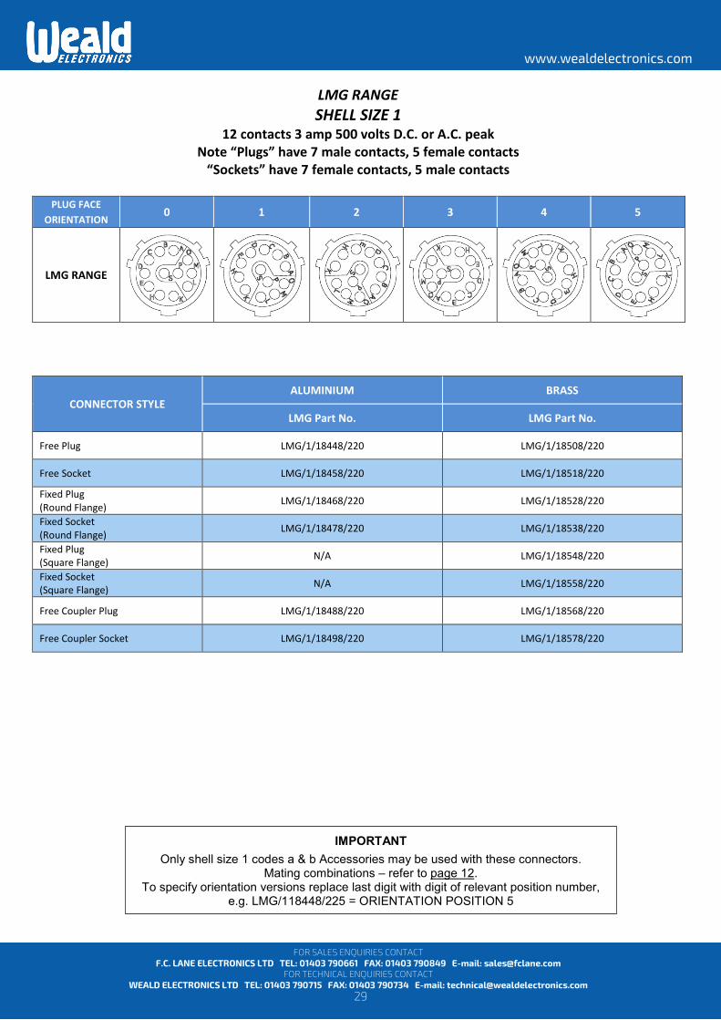
LMG RANGE SHELL SIZE 1
12 contacts 3 amp 500 volts D.C. or A.C. peak Note “Plugs” have 7 male contacts, 5 female contacts
“Sockets” have 7 female contacts, 5 male contacts
PLUG FACE ORIENTATION 0 1 2 3 4 5
LMG RANGE
CONNECTOR STYLE ALUMINIUM BRASS
LMG Part No. LMG Part No.
Free Plug LMG/1/18448/220 LMG/1/18508/220
Free Socket LMG/1/18458/220 LMG/1/18518/220 Fixed Plug (Round Flange) LMG/1/18468/220 LMG/1/18528/220 Fixed Socket (Round Flange) LMG/1/18478/220 LMG/1/18538/220 Fixed Plug (Square Flange) N/A LMG/1/18548/220 Fixed Socket (Square Flange) N/A LMG/1/18558/220
Free Coupler Plug LMG/1/18488/220 LMG/1/18568/220
Free Coupler Socket LMG/1/18498/220 LMG/1/18578/220
IMPORTANT
Only shell size 1 codes a & b Accessories may be used with these connectors. Mating combinations – refer to page 12.
To specify orientation versions replace last digit with digit of relevant position number, e.g. LMG/118448/225 = ORIENTATION POSITION 5

30
www.wealdelectronics.com
FOR SALES ENQUIRIES CONTACT F.C. LANE ELECTRONICS LTD TEL: 01403 790661 FAX: 01403 790849 E-mail: [email protected]
FOR TECHNICAL ENQUIRIES CONTACT WEALD ELECTRONICS LTD TEL: 01403 790715 FAX: 01403 790734 E-mail: [email protected]
LMF / LMG RANGE SHELL SIZE 2
12 contacts 5 amps
PLUG FACE ORIENTATION 0 1 2 3 4 5
LMF RANGE 250 volts D.C. or A.C. peak
LMG RANGE 500 volts D.C. or A.C. peak
CONNECTOR STYLE ALUMINIUM BRASS
LMF Part No. LMG Part No. LMF Part No. LMG Part No.
Free Plug LMF/1/40029/320 LMG/1/07029/220 LMF/1/40229/520 LMG/1/07229/220
Free Socket LMF/1/40009/320 LMG/1/07009/220 LMF/1/40209/520 LMG/1/07209/220
Fixed Plug (Round Flange) LMF/1/40069/320 LMG/1/07069/220 LMF/1/40269/520 LMG/1/07349/220
Fixed Socket (Round Flange) LMF/1/40049/320 LMG/1/07049/220 LMF/1/40249/520 LMG/1/07329/220
Fixed Plug (Round Flange with Outlet Nut) LMF/1/40149/320 N/A N/A N/A
Fixed Socket (Round Flange With Outlet Nut) LMF/1/40129/320 N/A N/A N/A
Fixed Plug (Square Flange) N/A N/A LMF/1/40349/520 LMG/1/07269/220
Fixed Socket (Square Flange) N/A N/A LMF/1/40329/520 LMG/1/07249/220
Free Coupler Plug LMF/1/40109/320 LMG/1/07109/220 LMF/1/40309/520 LMG/1/07309/220
Free Coupler Socket LMF/1/40089/320 LMG/1/07089/220 LMF/1/40289/520 LMG/1/07289/220
Bulkhead Plug/Socket LMF/1/40189/320 N/A LMF/1/40389/520 N/A
Bulkhead Socket/Plug LMF/1/40169/320 N/A LMF/1/40369/520 N/A
IMPORTANT
Only shell size 2 codes c, d, e & f accessories may be used with these connectors. Mating combinations – refer to page 7 (for LMF) or page 12 (for LMG).
To specify orientation versions replace last digit with digit of relevant position number, e.g. LMF/1/40029/325 = ORIENTATION POSITION 5

31
www.wealdelectronics.com
FOR SALES ENQUIRIES CONTACT F.C. LANE ELECTRONICS LTD TEL: 01403 790661 FAX: 01403 790849 E-mail: [email protected]
FOR TECHNICAL ENQUIRIES CONTACT WEALD ELECTRONICS LTD TEL: 01403 790715 FAX: 01403 790734 E-mail: [email protected]
LMF / LMG RANGE SHELL SIZE 3
13 contacts 12 amps
PLUG FACE ORIENTATION 0 1 2 3 4 5
LMF RANGE 250 volts D.C. or A.C. peak
LMG RANGE 500 volts D.C. or A.C. peak
CONNECTOR STYLE ALUMINIUM BRASS
LMF Part No. LMG Part No. LMF Part No. LMG Part No.
Free Plug LMF/1/40434/320 LMG/1/07034/220 LMF/1/40634/520 LMG/1/07234/220
Free Socket LMF/1/40414/320 LMG/1/07014/220 LMF/1/40614/520 LMG/1/07214/220
Fixed Plug (Round Flange) LMF/1/40474/320 LMG/1/07074/220 LMF/1/40674/520 LMG/1/07354/220
Fixed Socket (Round Flange) LMF/1/40454/320 LMG/1/07054/220 LMF/1/40654/520 LMG/1/07334/220
Fixed Plug (Round Flange with Outlet Nut) LMF/1/40554/320 N/A N/A N/A
Fixed Socket (Round Flange With Outlet Nut) LMF/1/40534/320 N/A N/A N/A
Fixed Plug (Square Flange) N/A N/A LMF/1/40754/520 LMG/1/07274/220
Fixed Socket (Square Flange) N/A N/A LMF/1/40734/520 LMG/1/07254/220
Free Coupler Plug LMF/1/40514/320 LMG/1/07114/220 LMF/1/40714/520 LMG/1/07314/220
Free Coupler Socket LMF/1/40494/320 LMG/1/07094/220 LMF/1/40694/520 LMG/1/07294/220
Bulkhead Plug/Socket N/A N/A N/A N/A
Bulkhead Socket/Plug N/A N/A N/A N/A
IMPORTANT
Only shell size 3 codes g, h & i accessories may be used with these connectors. Mating combinations – refer to page 7 (for LMF) or page 12 (for LMG).
To specify orientation versions replace last digit with digit of relevant position number, e.g. LMF/1/40034/325 = ORIENTATION POSITION 5
32
www.wealdelectronics.com
FOR SALES ENQUIRIES CONTACT F.C. LANE ELECTRONICS LTD TEL: 01403 790661 FAX: 01403 790849 E-mail: [email protected]
FOR TECHNICAL ENQUIRIES CONTACT WEALD ELECTRONICS LTD TEL: 01403 790715 FAX: 01403 790734 E-mail: [email protected]
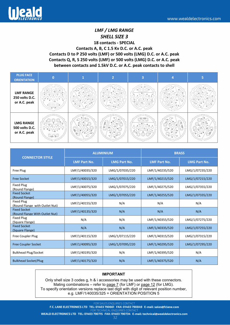
LMF / LMG RANGE SHELL SIZE 3
18 contacts - SPECIAL Contacts A, B, C 1.5 Kv D.C. or A.C. peak
Contacts D to P 250 volts (LMF) or 500 volts (LMG) D.C. or A.C. peak Contacts Q, R, S 250 volts (LMF) or 500 volts (LMG) D.C. or A.C. peak
between contacts and 1.5kV D.C. or A.C. peak contacts to shell
PLUG FACE ORIENTATION 0 1 2 3 4 5
LMF RANGE 250 volts D.C. or A.C. peak
LMG RANGE 500 volts D.C. or A.C. peak
CONNECTOR STYLE ALUMINIUM BRASS
LMF Part No. LMG Part No. LMF Part No. LMG Part No.
Free Plug LMF/1/40035/320 LMG/1/07035/220 LMF/1/40235/520 LMG/1/07235/220
Free Socket LMF/1/40015/320 LMG/1/07015/220 LMF/1/40215/520 LMG/1/07215/220
Fixed Plug (Round Flange)
LMF/1/40075/320 LMG/1/07075/220 LMF/1/40275/520 LMG/1/07355/220
Fixed Socket (Round Flange) LMF/1/40055/320 LMG/1/07055/220 LMF/1/40255/520 LMG/1/07335/220
Fixed Plug (Round Flange with Outlet Nut) LMF/1/40155/320 N/A N/A N/A
Fixed Socket (Round Flange With Outlet Nut) LMF/1/40135/320 N/A N/A N/A
Fixed Plug (Square Flange) N/A N/A LMF/1/40355/520 LMG/1/07275/220
Fixed Socket (Square Flange) N/A N/A LMF/1/40335/520 LMG/1/07255/220
Free Coupler Plug LMF/1/40115/320 LMG/1/07115/220 LMF/1/40315/520 LMG/1/07315/220
Free Coupler Socket LMF/1/40095/320 LMG/1/07095/220 LMF/1/40295/520 LMG/1/07295/220
Bulkhead Plug/Socket LMF/1/40195/320 N/A LMF/1/40395/520 N/A
Bulkhead Socket/Plug LMF/1/40175/320 N/A LMF/1/40375/520 N/A
IMPORTANT
Only shell size 3 codes g, h & i accessories may be used with these connectors. Mating combinations – refer to page 7 (for LMF) or page 12 (for LMG).
To specify orientation versions replace last digit with digit of relevant position number, e.g. LMF/1/40035/325 = ORIENTATION POSITION 5
33
www.wealdelectronics.com
FOR SALES ENQUIRIES CONTACT F.C. LANE ELECTRONICS LTD TEL: 01403 790661 FAX: 01403 790849 E-mail: [email protected]
FOR TECHNICAL ENQUIRIES CONTACT WEALD ELECTRONICS LTD TEL: 01403 790715 FAX: 01403 790734 E-mail: [email protected]
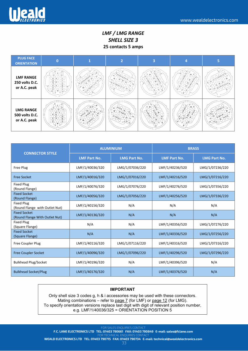
LMF / LMG RANGE SHELL SIZE 3
25 contacts 5 amps
PLUG FACE ORIENTATION 0 1 2 3 4 5
LMF RANGE 250 volts D.C. or A.C. peak
LMG RANGE 500 volts D.C. or A.C. peak
CONNECTOR STYLE ALUMINIUM BRASS
LMF Part No. LMG Part No. LMF Part No. LMG Part No.
Free Plug LMF/1/40036/320 LMG/1/07036/220 LMF/1/40236/520 LMG/1/07236/220
Free Socket LMF/1/40016/320 LMG/1/07016/220 LMF/1/40216/520 LMG/1/07216/220
Fixed Plug (Round Flange) LMF/1/40076/320 LMG/1/07076/220 LMF/1/40276/520 LMG/1/07356/220
Fixed Socket (Round Flange) LMF/1/40056/320 LMG/1/07056/220 LMF/1/40256/520 LMG/1/07336/220
Fixed Plug (Round Flange with Outlet Nut) LMF/1/40156/320 N/A N/A N/A
Fixed Socket (Round Flange With Outlet Nut) LMF/1/40136/320 N/A N/A N/A
Fixed Plug (Square Flange) N/A N/A LMF/1/40356/520 LMG/1/07276/220
Fixed Socket (Square Flange) N/A N/A LMF/1/40336/520 LMG/1/07256/220
Free Coupler Plug LMF/1/40116/320 LMG/1/07116/220 LMF/1/40316/520 LMG/1/07316/220
Free Coupler Socket LMF/1/40096/320 LMG/1/07096/220 LMF/1/40296/520 LMG/1/07296/220
Bulkhead Plug/Socket LMF/1/40196/320 N/A LMF/1/40396/520 N/A
Bulkhead Socket/Plug LMF/1/40176/320 N/A LMF/1/40376/520 N/A
IMPORTANT
Only shell size 3 codes g, h & i accessories may be used with these connectors. Mating combinations – refer to page 7 (for LMF) or page 12 (for LMG).
To specify orientation versions replace last digit with digit of relevant position number, e.g. LMF/1/40036/325 = ORIENTATION POSITION 5
34
www.wealdelectronics.com
FOR SALES ENQUIRIES CONTACT F.C. LANE ELECTRONICS LTD TEL: 01403 790661 FAX: 01403 790849 E-mail: [email protected]
FOR TECHNICAL ENQUIRIES CONTACT WEALD ELECTRONICS LTD TEL: 01403 790715 FAX: 01403 790734 E-mail: [email protected]
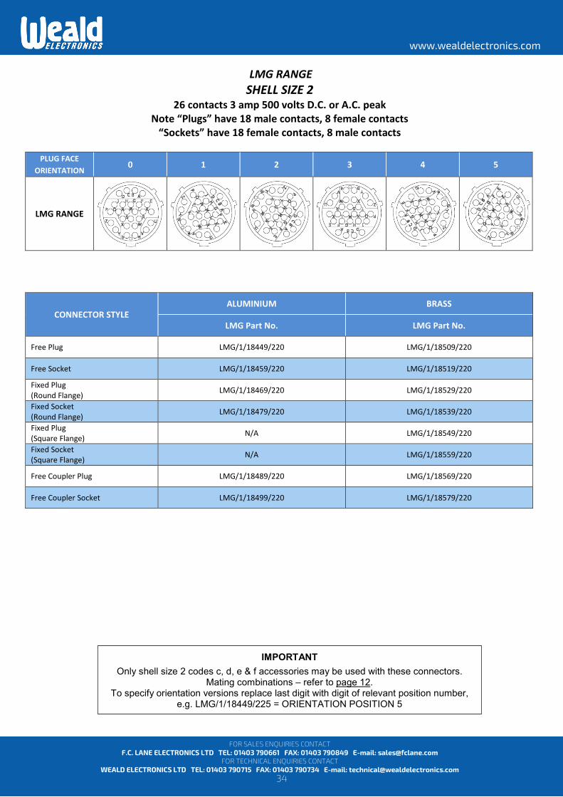
LMG RANGE SHELL SIZE 2
26 contacts 3 amp 500 volts D.C. or A.C. peak Note “Plugs” have 18 male contacts, 8 female contacts
“Sockets” have 18 female contacts, 8 male contacts
PLUG FACE ORIENTATION 0 1 2 3 4 5
LMG RANGE
CONNECTOR STYLE ALUMINIUM BRASS
LMG Part No. LMG Part No.
Free Plug LMG/1/18449/220 LMG/1/18509/220
Free Socket LMG/1/18459/220 LMG/1/18519/220 Fixed Plug (Round Flange) LMG/1/18469/220 LMG/1/18529/220 Fixed Socket (Round Flange) LMG/1/18479/220 LMG/1/18539/220 Fixed Plug (Square Flange) N/A LMG/1/18549/220 Fixed Socket (Square Flange) N/A LMG/1/18559/220
Free Coupler Plug LMG/1/18489/220 LMG/1/18569/220
Free Coupler Socket LMG/1/18499/220 LMG/1/18579/220
IMPORTANT
Only shell size 2 codes c, d, e & f accessories may be used with these connectors. Mating combinations – refer to page 12.
To specify orientation versions replace last digit with digit of relevant position number, e.g. LMG/1/18449/225 = ORIENTATION POSITION 5
35
www.wealdelectronics.com
FOR SALES ENQUIRIES CONTACT F.C. LANE ELECTRONICS LTD TEL: 01403 790661 FAX: 01403 790849 E-mail: [email protected]
FOR TECHNICAL ENQUIRIES CONTACT WEALD ELECTRONICS LTD TEL: 01403 790715 FAX: 01403 790734 E-mail: [email protected]
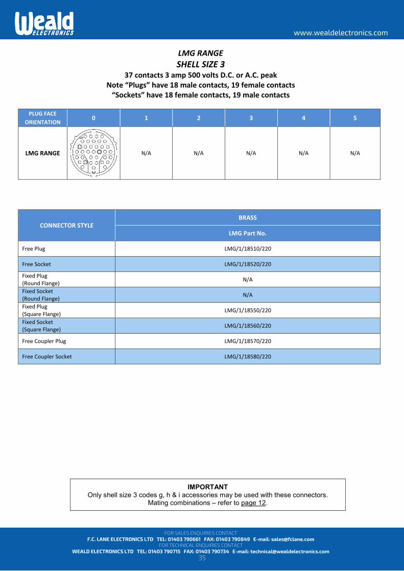
LMG RANGE SHELL SIZE 3
37 contacts 3 amp 500 volts D.C. or A.C. peak Note “Plugs” have 18 male contacts, 19 female contacts
“Sockets” have 18 female contacts, 19 male contacts
PLUG FACE ORIENTATION 0 1 2 3 4 5
LMG RANGE
N/A N/A N/A N/A N/A
CONNECTOR STYLE BRASS
LMG Part No.
Free Plug LMG/1/18510/220
Free Socket LMG/1/18520/220 Fixed Plug (Round Flange) N/A Fixed Socket (Round Flange) N/A Fixed Plug (Square Flange) LMG/1/18550/220 Fixed Socket (Square Flange) LMG/1/18560/220
Free Coupler Plug LMG/1/18570/220
Free Coupler Socket LMG/1/18580/220
IMPORTANT Only shell size 3 codes g, h & i accessories may be used with these connectors.
Mating combinations – refer to page 12.
36
www.wealdelectronics.com
FOR SALES ENQUIRIES CONTACT F.C. LANE ELECTRONICS LTD TEL: 01403 790661 FAX: 01403 790849 E-mail: [email protected]
FOR TECHNICAL ENQUIRIES CONTACT WEALD ELECTRONICS LTD TEL: 01403 790715 FAX: 01403 790734 E-mail: [email protected]
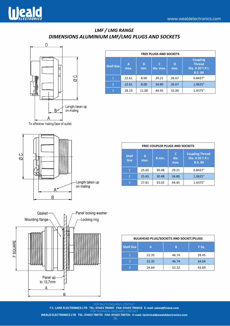
LMF / LMG RANGE DIMENSIONS ALUMINIUM LMF/LMG PLUGS AND SOCKETS
FREE PLUGS AND SOCKETS
Shell Size A max.
B min.
C dia. max.
D max.
Coupling Thread
Dia. X 20 T.P.I. B.S. 84
1 22.61 8.00 29.21 26.67 0.8437"
2 22.61 8.00 34.80 26.67 1.0625"
3 28.19 11.00 44.45 32.00 1.4375"
FREE COUPLER PLUGS AND SOCKETS
Shell Size
A max. B min.
C dia.
max.
Coupling Thread Dia. X 20 T.P.I.
B.S. 84
1 25.65 30.48 29.21 0.8437"
2 25.65 30.48 34.80 1.0625"
3 27.81 33.02 44.45 1.4375"
BULKHEAD PLUG/SOCKETS AND SOCKET/PLUGS
Shell Size A B F Sq.
1 22.35 46.74 28.45
2 22.35 46.74 34.04
3 24.64 52.32 43.69
37
www.wealdelectronics.com
FOR SALES ENQUIRIES CONTACT F.C. LANE ELECTRONICS LTD TEL: 01403 790661 FAX: 01403 790849 E-mail: [email protected]
FOR TECHNICAL ENQUIRIES CONTACT WEALD ELECTRONICS LTD TEL: 01403 790715 FAX: 01403 790734 E-mail: [email protected]
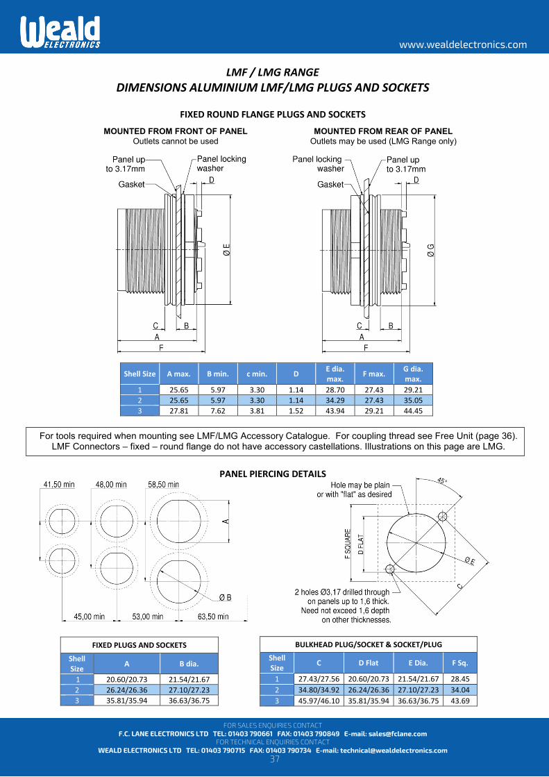
LMF / LMG RANGE DIMENSIONS ALUMINIUM LMF/LMG PLUGS AND SOCKETS
FIXED ROUND FLANGE PLUGS AND SOCKETS
PANEL PIERCING DETAILS
FIXED PLUGS AND SOCKETS
Shell Size A B dia.
1 20.60/20.73 21.54/21.67 2 26.24/26.36 27.10/27.23 3 35.81/35.94 36.63/36.75
Shell Size A max. B min. c min. D E dia. max. F max. G dia.
max. 1 25.65 5.97 3.30 1.14 28.70 27.43 29.21 2 25.65 5.97 3.30 1.14 34.29 27.43 35.05 3 27.81 7.62 3.81 1.52 43.94 29.21 44.45
BULKHEAD PLUG/SOCKET & SOCKET/PLUG
Shell Size C D Flat E Dia. F Sq.
1 27.43/27.56 20.60/20.73 21.54/21.67 28.45 2 34.80/34.92 26.24/26.36 27.10/27.23 34.04 3 45.97/46.10 35.81/35.94 36.63/36.75 43.69
MOUNTED FROM FRONT OF PANEL Outlets cannot be used
MOUNTED FROM REAR OF PANEL Outlets may be used (LMG Range only)
For tools required when mounting see LMF/LMG Accessory Catalogue. For coupling thread see Free Unit (page 36). LMF Connectors – fixed – round flange do not have accessory castellations. Illustrations on this page are LMG.

38
www.wealdelectronics.com
FOR SALES ENQUIRIES CONTACT F.C. LANE ELECTRONICS LTD TEL: 01403 790661 FAX: 01403 790849 E-mail: [email protected]
FOR TECHNICAL ENQUIRIES CONTACT WEALD ELECTRONICS LTD TEL: 01403 790715 FAX: 01403 790734 E-mail: [email protected]
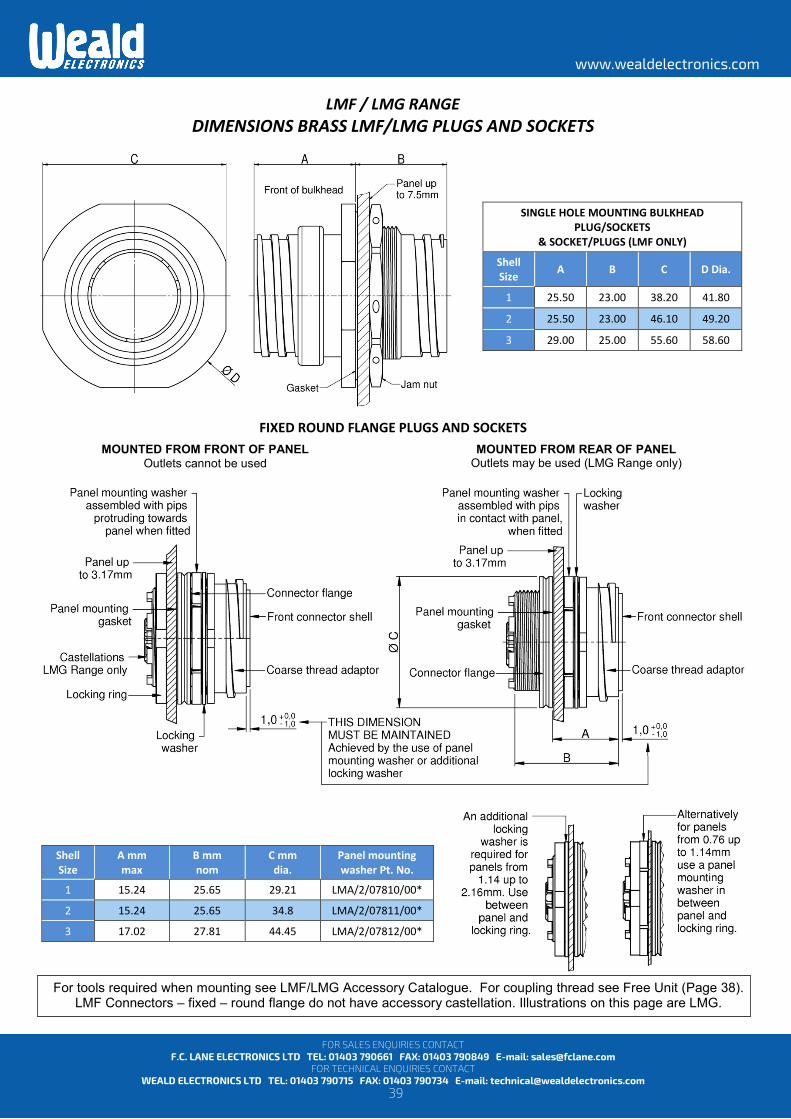
LMF / LMG RANGE DIMENSIONS BRASS LMF/LMG PLUGS AND SOCKETS
* - Relates to size 3 connectors with 37 contacts.
FREE PLUGS AND SOCKETS
Shell Size A max.
B min.
C dia. max.
D max. Coupling Thread (Nominal)
1 22.61 8 32.51 26.67 Major Dia. 1.000" X 6 T.P.I. Modified Acme
2 22.61 8 38.61 26.67 Major Dia. 1.219" X 6 T.P.I. Modified Acme
3 28.19 11 49.02 32.00 Major Dia. 1.605" X 6 T.P.I. Modified Acme
3 HD* 28.19 11 49.02 32.00 Major Dia. 1.605" X 8 T.P.I. Twin-Start Modified Acme
FREE COUPLER PLUGS AND SOCKETS
Shell Size A max. B max. C dia.
max. Coupling Thread (Nominal)
1 26.92 30.48 32.51 Major Dia. 1.000" X 6 T.P.I. Modified Acme
2 26.92 30.48 38.61 Major Dia. 1.219" X 6 T.P.I. Modified Acme
3 27.81 33.02 49.02 Major Dia. 1.605" X 6 T.P.I. Modified Acme
3 HD* 27.81 33.02 49.02 Major Dia. 1.605" X 8 T.P.I. Twin-Start Modified Acme
SQUARE FLANGE BULKHEAD PLUG/SOCKETS & SOCKET/PLUGS (LMF ONLY)
Shell Size A B C Sq.
1 29.21 20.07 33.78
2 29.21 20.07 41.91
3 31.50 23.37 48.77
39
www.wealdelectronics.com
FOR SALES ENQUIRIES CONTACT F.C. LANE ELECTRONICS LTD TEL: 01403 790661 FAX: 01403 790849 E-mail: [email protected]
FOR TECHNICAL ENQUIRIES CONTACT WEALD ELECTRONICS LTD TEL: 01403 790715 FAX: 01403 790734 E-mail: [email protected]
LMF / LMG RANGE DIMENSIONS BRASS LMF/LMG PLUGS AND SOCKETS
FIXED ROUND FLANGE PLUGS AND SOCKETS
SINGLE HOLE MOUNTING BULKHEAD PLUG/SOCKETS
& SOCKET/PLUGS (LMF ONLY)
Shell Size A B C D Dia.
1 25.50 23.00 38.20 41.80
2 25.50 23.00 46.10 49.20
3 29.00 25.00 55.60 58.60
Shell Size
A mm max
B mm nom
C mm dia.
Panel mounting washer Pt. No.
1 15.24 25.65 29.21 LMA/2/07810/00*
2 15.24 25.65 34.8 LMA/2/07811/00*
3 17.02 27.81 44.45 LMA/2/07812/00*
MOUNTED FROM FRONT OF PANEL Outlets cannot be used
MOUNTED FROM REAR OF PANEL Outlets may be used (LMG Range only)
For tools required when mounting see LMF/LMG Accessory Catalogue. For coupling thread see Free Unit (Page 38). LMF Connectors – fixed – round flange do not have accessory castellation. Illustrations on this page are LMG.

40
www.wealdelectronics.com
FOR SALES ENQUIRIES CONTACT F.C. LANE ELECTRONICS LTD TEL: 01403 790661 FAX: 01403 790849 E-mail: [email protected]
FOR TECHNICAL ENQUIRIES CONTACT WEALD ELECTRONICS LTD TEL: 01403 790715 FAX: 01403 790734 E-mail: [email protected]
LMF / LMG RANGE DIMENSIONS BRASS LMF/LMG PLUGS AND SOCKETS
FIXED SQUARE FLANGE PLUGS AND SOCKETS
Shell Size A max. B C max. D K Sq. max
1 19.94 6.60 17.14 9.65 34.04
2 19.94 6.60 17.14 9.65 42.16
3 22.10 7.11 18.29 10.16 49.02
MOUNTED FROM FRONT OF PANEL
MOUNTED FROM REAR OF PANEL
Bolts should be mounted with bolt heads on the mating side of plug or socket
CORNER BOLT SEALING DETAILS
IMPORTANT
These plugs and sockets are supplied with panel-mounting gasket. Corner bushes, nuts,
bolts and washers must be ordered as additional items. For details see LMF/LMG
Accessory Catalogue (page 11).
Where outlets are to be used, outlet nuts must be ordered as additional items. For details see
LMF/LMG Accessory Catalogue (page 10).

41
www.wealdelectronics.com
FOR SALES ENQUIRIES CONTACT F.C. LANE ELECTRONICS LTD TEL: 01403 790661 FAX: 01403 790849 E-mail: [email protected]
FOR TECHNICAL ENQUIRIES CONTACT WEALD ELECTRONICS LTD TEL: 01403 790715 FAX: 01403 790734 E-mail: [email protected]
LMF / LMG RANGE DIMENSIONS BRASS LMF/LMG PLUGS AND SOCKETS
PANEL PIERCING DETAILS
FIXED PLUGS AND SOCKETS
Shell Size
A min/max B dia.
1 20.60/20.73 21.54/21.67 2 26.24/26.36 27.10/27.23 3 35.81/35.94 36.63/36.75
FIXED SQUARE FLANGE PLUGS AND SOCKETS
Shell Size
A dia. min/max B dia. C D
nom. L
1 25.27/25.4 3.96 25.4 33.78 36.83
2 30.86/30.99 5.10 31.37 41.91 43.43
3 40.39/40.51 5.10 38.48 48.77 55.63
SINGLE HOLE MOUNTING BULKHEAD PLUG/SOCKETS
& SOCKET/PLUGS (LMF ONLY) Shell Size A B dia.
1 27.56/27.81 28.83/29.08 2 33.91/34.16 35.18/35.43 3 43.43/43.68 44.70/44.95
SQUARE FLANGE BULKHEAD PLUG/SOCKETS & SOCKET/PLUGS (LMF ONLY)
Shell Size A B C dia. D dia.
1 25.40 33.78 25.53/25.65 3.73 2 31.37 41.91 31.11/31.24 4.85 3 38.48 48.77 40.64/40.77 4.85
42
www.wealdelectronics.com
FOR SALES ENQUIRIES CONTACT F.C. LANE ELECTRONICS LTD TEL: 01403 790661 FAX: 01403 790849 E-mail: [email protected]
FOR TECHNICAL ENQUIRIES CONTACT WEALD ELECTRONICS LTD TEL: 01403 790715 FAX: 01403 790734 E-mail: [email protected]
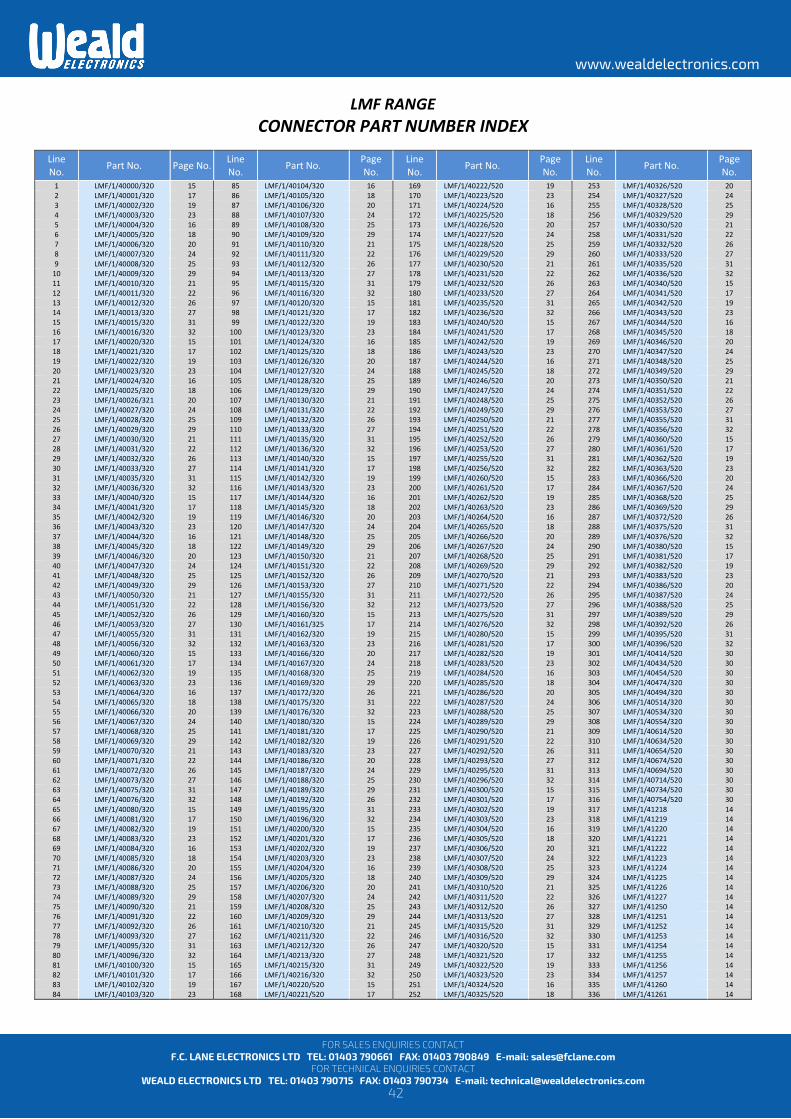
LMF RANGE CONNECTOR PART NUMBER INDEX
Line No. Part No. Page No. Line
No. Part No. Page No.
Line No. Part No. Page
No. Line No. Part No. Page
No. 1 LMF/1/40000/320 15 85 LMF/1/40104/320 16 169 LMF/1/40222/520 19 253 LMF/1/40326/520 20 2 LMF/1/40001/320 17 86 LMF/1/40105/320 18 170 LMF/1/40223/520 23 254 LMF/1/40327/520 24 3 LMF/1/40002/320 19 87 LMF/1/40106/320 20 171 LMF/1/40224/520 16 255 LMF/1/40328/520 25 4 LMF/1/40003/320 23 88 LMF/1/40107/320 24 172 LMF/1/40225/520 18 256 LMF/1/40329/520 29 5 LMF/1/40004/320 16 89 LMF/1/40108/320 25 173 LMF/1/40226/520 20 257 LMF/1/40330/520 21 6 LMF/1/40005/320 18 90 LMF/1/40109/320 29 174 LMF/1/40227/520 24 258 LMF/1/40331/520 22 7 LMF/1/40006/320 20 91 LMF/1/40110/320 21 175 LMF/1/40228/520 25 259 LMF/1/40332/520 26 8 LMF/1/40007/320 24 92 LMF/1/40111/320 22 176 LMF/1/40229/520 29 260 LMF/1/40333/520 27 9 LMF/1/40008/320 25 93 LMF/1/40112/320 26 177 LMF/1/40230/520 21 261 LMF/1/40335/520 31
10 LMF/1/40009/320 29 94 LMF/1/40113/320 27 178 LMF/1/40231/520 22 262 LMF/1/40336/520 32 11 LMF/1/40010/320 21 95 LMF/1/40115/320 31 179 LMF/1/40232/520 26 263 LMF/1/40340/520 15 12 LMF/1/40011/320 22 96 LMF/1/40116/320 32 180 LMF/1/40233/520 27 264 LMF/1/40341/520 17 13 LMF/1/40012/320 26 97 LMF/1/40120/320 15 181 LMF/1/40235/520 31 265 LMF/1/40342/520 19 14 LMF/1/40013/320 27 98 LMF/1/40121/320 17 182 LMF/1/40236/520 32 266 LMF/1/40343/520 23 15 LMF/1/40015/320 31 99 LMF/1/40122/320 19 183 LMF/1/40240/520 15 267 LMF/1/40344/520 16 16 LMF/1/40016/320 32 100 LMF/1/40123/320 23 184 LMF/1/40241/520 17 268 LMF/1/40345/520 18 17 LMF/1/40020/320 15 101 LMF/1/40124/320 16 185 LMF/1/40242/520 19 269 LMF/1/40346/520 20 18 LMF/1/40021/320 17 102 LMF/1/40125/320 18 186 LMF/1/40243/520 23 270 LMF/1/40347/520 24 19 LMF/1/40022/320 19 103 LMF/1/40126/320 20 187 LMF/1/40244/520 16 271 LMF/1/40348/520 25 20 LMF/1/40023/320 23 104 LMF/1/40127/320 24 188 LMF/1/40245/520 18 272 LMF/1/40349/520 29 21 LMF/1/40024/320 16 105 LMF/1/40128/320 25 189 LMF/1/40246/520 20 273 LMF/1/40350/520 21 22 LMF/1/40025/320 18 106 LMF/1/40129/320 29 190 LMF/1/40247/520 24 274 LMF/1/40351/520 22 23 LMF/1/40026/321 20 107 LMF/1/40130/320 21 191 LMF/1/40248/520 25 275 LMF/1/40352/520 26 24 LMF/1/40027/320 24 108 LMF/1/40131/320 22 192 LMF/1/40249/520 29 276 LMF/1/40353/520 27 25 LMF/1/40028/320 25 109 LMF/1/40132/320 26 193 LMF/1/40250/520 21 277 LMF/1/40355/520 31 26 LMF/1/40029/320 29 110 LMF/1/40133/320 27 194 LMF/1/40251/520 22 278 LMF/1/40356/520 32 27 LMF/1/40030/320 21 111 LMF/1/40135/320 31 195 LMF/1/40252/520 26 279 LMF/1/40360/520 15 28 LMF/1/40031/320 22 112 LMF/1/40136/320 32 196 LMF/1/40253/520 27 280 LMF/1/40361/520 17 29 LMF/1/40032/320 26 113 LMF/1/40140/320 15 197 LMF/1/40255/520 31 281 LMF/1/40362/520 19 30 LMF/1/40033/320 27 114 LMF/1/40141/320 17 198 LMF/1/40256/520 32 282 LMF/1/40363/520 23 31 LMF/1/40035/320 31 115 LMF/1/40142/320 19 199 LMF/1/40260/520 15 283 LMF/1/40366/520 20 32 LMF/1/40036/320 32 116 LMF/1/40143/320 23 200 LMF/1/40261/520 17 284 LMF/1/40367/520 24 33 LMF/1/40040/320 15 117 LMF/1/40144/320 16 201 LMF/1/40262/520 19 285 LMF/1/40368/520 25 34 LMF/1/40041/320 17 118 LMF/1/40145/320 18 202 LMF/1/40263/520 23 286 LMF/1/40369/520 29 35 LMF/1/40042/320 19 119 LMF/1/40146/320 20 203 LMF/1/40264/520 16 287 LMF/1/40372/520 26 36 LMF/1/40043/320 23 120 LMF/1/40147/320 24 204 LMF/1/40265/520 18 288 LMF/1/40375/520 31 37 LMF/1/40044/320 16 121 LMF/1/40148/320 25 205 LMF/1/40266/520 20 289 LMF/1/40376/520 32 38 LMF/1/40045/320 18 122 LMF/1/40149/320 29 206 LMF/1/40267/520 24 290 LMF/1/40380/520 15 39 LMF/1/40046/320 20 123 LMF/1/40150/320 21 207 LMF/1/40268/520 25 291 LMF/1/40381/520 17 40 LMF/1/40047/320 24 124 LMF/1/40151/320 22 208 LMF/1/40269/520 29 292 LMF/1/40382/520 19 41 LMF/1/40048/320 25 125 LMF/1/40152/320 26 209 LMF/1/40270/520 21 293 LMF/1/40383/520 23 42 LMF/1/40049/320 29 126 LMF/1/40153/320 27 210 LMF/1/40271/520 22 294 LMF/1/40386/520 20 43 LMF/1/40050/320 21 127 LMF/1/40155/320 31 211 LMF/1/40272/520 26 295 LMF/1/40387/520 24 44 LMF/1/40051/320 22 128 LMF/1/40156/320 32 212 LMF/1/40273/520 27 296 LMF/1/40388/520 25 45 LMF/1/40052/320 26 129 LMF/1/40160/320 15 213 LMF/1/40275/520 31 297 LMF/1/40389/520 29 46 LMF/1/40053/320 27 130 LMF/1/40161/325 17 214 LMF/1/40276/520 32 298 LMF/1/40392/520 26 47 LMF/1/40055/320 31 131 LMF/1/40162/320 19 215 LMF/1/40280/520 15 299 LMF/1/40395/520 31 48 LMF/1/40056/320 32 132 LMF/1/40163/320 23 216 LMF/1/40281/520 17 300 LMF/1/40396/520 32 49 LMF/1/40060/320 15 133 LMF/1/40166/320 20 217 LMF/1/40282/520 19 301 LMF/1/40414/520 30 50 LMF/1/40061/320 17 134 LMF/1/40167/320 24 218 LMF/1/40283/520 23 302 LMF/1/40434/520 30 51 LMF/1/40062/320 19 135 LMF/1/40168/320 25 219 LMF/1/40284/520 16 303 LMF/1/40454/520 30 52 LMF/1/40063/320 23 136 LMF/1/40169/320 29 220 LMF/1/40285/520 18 304 LMF/1/40474/320 30 53 LMF/1/40064/320 16 137 LMF/1/40172/320 26 221 LMF/1/40286/520 20 305 LMF/1/40494/320 30 54 LMF/1/40065/320 18 138 LMF/1/40175/320 31 222 LMF/1/40287/520 24 306 LMF/1/40514/320 30 55 LMF/1/40066/320 20 139 LMF/1/40176/320 32 223 LMF/1/40288/520 25 307 LMF/1/40534/320 30 56 LMF/1/40067/320 24 140 LMF/1/40180/320 15 224 LMF/1/40289/520 29 308 LMF/1/40554/320 30 57 LMF/1/40068/320 25 141 LMF/1/40181/320 17 225 LMF/1/40290/520 21 309 LMF/1/40614/520 30 58 LMF/1/40069/320 29 142 LMF/1/40182/320 19 226 LMF/1/40291/520 22 310 LMF/1/40634/520 30 59 LMF/1/40070/320 21 143 LMF/1/40183/320 23 227 LMF/1/40292/520 26 311 LMF/1/40654/520 30 60 LMF/1/40071/320 22 144 LMF/1/40186/320 20 228 LMF/1/40293/520 27 312 LMF/1/40674/520 30 61 LMF/1/40072/320 26 145 LMF/1/40187/320 24 229 LMF/1/40295/520 31 313 LMF/1/40694/520 30 62 LMF/1/40073/320 27 146 LMF/1/40188/320 25 230 LMF/1/40296/520 32 314 LMF/1/40714/520 30 63 LMF/1/40075/320 31 147 LMF/1/40189/320 29 231 LMF/1/40300/520 15 315 LMF/1/40734/520 30 64 LMF/1/40076/320 32 148 LMF/1/40192/320 26 232 LMF/1/40301/520 17 316 LMF/1/40754/520 30 65 LMF/1/40080/320 15 149 LMF/1/40195/320 31 233 LMF/1/40302/520 19 317 LMF/1/41218 14 66 LMF/1/40081/320 17 150 LMF/1/40196/320 32 234 LMF/1/40303/520 23 318 LMF/1/41219 14 67 LMF/1/40082/320 19 151 LMF/1/40200/320 15 235 LMF/1/40304/520 16 319 LMF/1/41220 14 68 LMF/1/40083/320 23 152 LMF/1/40201/320 17 236 LMF/1/40305/520 18 320 LMF/1/41221 14 69 LMF/1/40084/320 16 153 LMF/1/40202/320 19 237 LMF/1/40306/520 20 321 LMF/1/41222 14 70 LMF/1/40085/320 18 154 LMF/1/40203/320 23 238 LMF/1/40307/520 24 322 LMF/1/41223 14 71 LMF/1/40086/320 20 155 LMF/1/40204/320 16 239 LMF/1/40308/520 25 323 LMF/1/41224 14 72 LMF/1/40087/320 24 156 LMF/1/40205/320 18 240 LMF/1/40309/520 29 324 LMF/1/41225 14 73 LMF/1/40088/320 25 157 LMF/1/40206/320 20 241 LMF/1/40310/520 21 325 LMF/1/41226 14 74 LMF/1/40089/320 29 158 LMF/1/40207/320 24 242 LMF/1/40311/520 22 326 LMF/1/41227 14 75 LMF/1/40090/320 21 159 LMF/1/40208/320 25 243 LMF/1/40312/520 26 327 LMF/1/41250 14 76 LMF/1/40091/320 22 160 LMF/1/40209/320 29 244 LMF/1/40313/520 27 328 LMF/1/41251 14 77 LMF/1/40092/320 26 161 LMF/1/40210/320 21 245 LMF/1/40315/520 31 329 LMF/1/41252 14 78 LMF/1/40093/320 27 162 LMF/1/40211/320 22 246 LMF/1/40316/520 32 330 LMF/1/41253 14 79 LMF/1/40095/320 31 163 LMF/1/40212/320 26 247 LMF/1/40320/520 15 331 LMF/1/41254 14 80 LMF/1/40096/320 32 164 LMF/1/40213/320 27 248 LMF/1/40321/520 17 332 LMF/1/41255 14 81 LMF/1/40100/320 15 165 LMF/1/40215/320 31 249 LMF/1/40322/520 19 333 LMF/1/41256 14 82 LMF/1/40101/320 17 166 LMF/1/40216/320 32 250 LMF/1/40323/520 23 334 LMF/1/41257 14 83 LMF/1/40102/320 19 167 LMF/1/40220/520 15 251 LMF/1/40324/520 16 335 LMF/1/41260 14 84 LMF/1/40103/320 23 168 LMF/1/40221/520 17 252 LMF/1/40325/520 18 336 LMF/1/41261 14
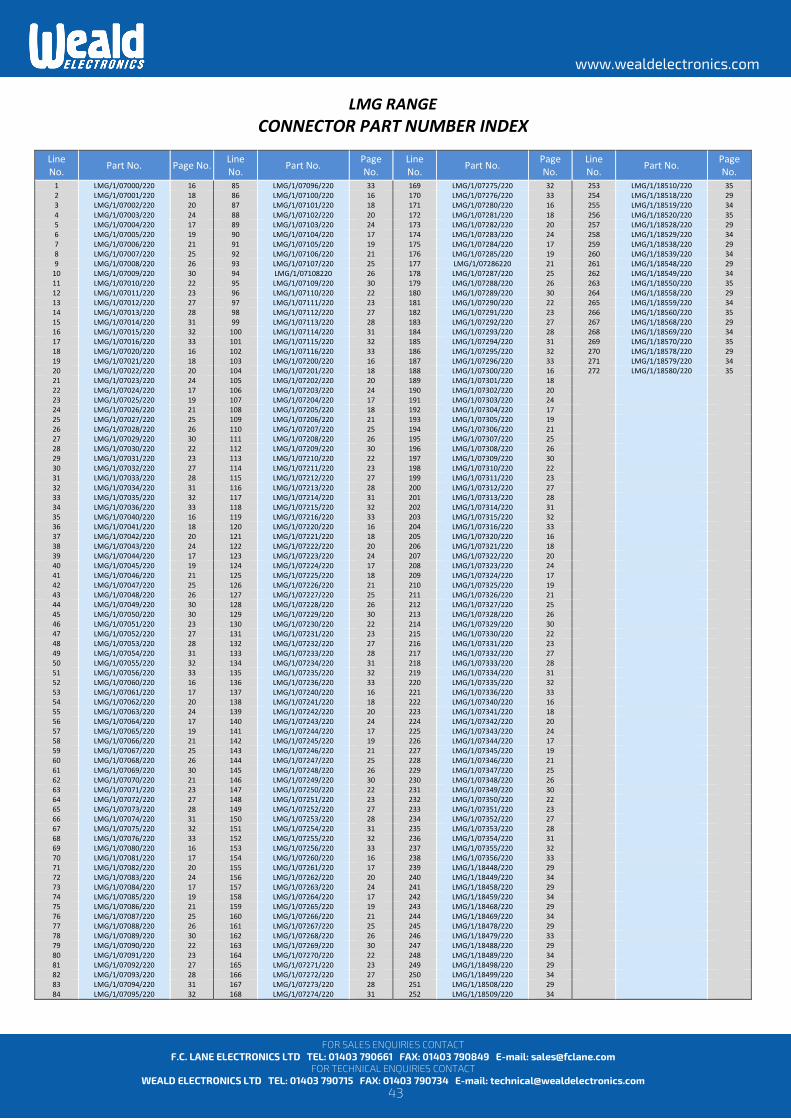
43
www.wealdelectronics.com
FOR SALES ENQUIRIES CONTACT F.C. LANE ELECTRONICS LTD TEL: 01403 790661 FAX: 01403 790849 E-mail: [email protected]
FOR TECHNICAL ENQUIRIES CONTACT WEALD ELECTRONICS LTD TEL: 01403 790715 FAX: 01403 790734 E-mail: [email protected]
LMG RANGE CONNECTOR PART NUMBER INDEX
Line No. Part No. Page No. Line
No. Part No. Page No.
Line No. Part No. Page
No. Line No. Part No. Page
No. 1 LMG/1/07000/220 16 85 LMG/1/07096/220 33 169 LMG/1/07275/220 32 253 LMG/1/18510/220 35 2 LMG/1/07001/220 18 86 LMG/1/07100/220 16 170 LMG/1/07276/220 33 254 LMG/1/18518/220 29 3 LMG/1/07002/220 20 87 LMG/1/07101/220 18 171 LMG/1/07280/220 16 255 LMG/1/18519/220 34 4 LMG/1/07003/220 24 88 LMG/1/07102/220 20 172 LMG/1/07281/220 18 256 LMG/1/18520/220 35 5 LMG/1/07004/220 17 89 LMG/1/07103/220 24 173 LMG/1/07282/220 20 257 LMG/1/18528/220 29 6 LMG/1/07005/220 19 90 LMG/1/07104/220 17 174 LMG/1/07283/220 24 258 LMG/1/18529/220 34 7 LMG/1/07006/220 21 91 LMG/1/07105/220 19 175 LMG/1/07284/220 17 259 LMG/1/18538/220 29 8 LMG/1/07007/220 25 92 LMG/1/07106/220 21 176 LMG/1/07285/220 19 260 LMG/1/18539/220 34 9 LMG/1/07008/220 26 93 LMG/1/07107/220 25 177 LMG/1/07286220 21 261 LMG/1/18548/220 29
10 LMG/1/07009/220 30 94 LMG/1/07108220 26 178 LMG/1/07287/220 25 262 LMG/1/18549/220 34 11 LMG/1/07010/220 22 95 LMG/1/07109/220 30 179 LMG/1/07288/220 26 263 LMG/1/18550/220 35 12 LMG/1/07011/220 23 96 LMG/1/07110/220 22 180 LMG/1/07289/220 30 264 LMG/1/18558/220 29 13 LMG/1/07012/220 27 97 LMG/1/07111/220 23 181 LMG/1/07290/220 22 265 LMG/1/18559/220 34 14 LMG/1/07013/220 28 98 LMG/1/07112/220 27 182 LMG/1/07291/220 23 266 LMG/1/18560/220 35 15 LMG/1/07014/220 31 99 LMG/1/07113/220 28 183 LMG/1/07292/220 27 267 LMG/1/18568/220 29 16 LMG/1/07015/220 32 100 LMG/1/07114/220 31 184 LMG/1/07293/220 28 268 LMG/1/18569/220 34 17 LMG/1/07016/220 33 101 LMG/1/07115/220 32 185 LMG/1/07294/220 31 269 LMG/1/18570/220 35 18 LMG/1/07020/220 16 102 LMG/1/07116/220 33 186 LMG/1/07295/220 32 270 LMG/1/18578/220 29 19 LMG/1/07021/220 18 103 LMG/1/07200/220 16 187 LMG/1/07296/220 33 271 LMG/1/18579/220 34 20 LMG/1/07022/220 20 104 LMG/1/07201/220 18 188 LMG/1/07300/220 16 272 LMG/1/18580/220 35 21 LMG/1/07023/220 24 105 LMG/1/07202/220 20 189 LMG/1/07301/220 18 22 LMG/1/07024/220 17 106 LMG/1/07203/220 24 190 LMG/1/07302/220 20 23 LMG/1/07025/220 19 107 LMG/1/07204/220 17 191 LMG/1/07303/220 24 24 LMG/1/07026/220 21 108 LMG/1/07205/220 18 192 LMG/1/07304/220 17 25 LMG/1/07027/220 25 109 LMG/1/07206/220 21 193 LMG/1/07305/220 19 26 LMG/1/07028/220 26 110 LMG/1/07207/220 25 194 LMG/1/07306/220 21 27 LMG/1/07029/220 30 111 LMG/1/07208/220 26 195 LMG/1/07307/220 25 28 LMG/1/07030/220 22 112 LMG/1/07209/220 30 196 LMG/1/07308/220 26 29 LMG/1/07031/220 23 113 LMG/1/07210/220 22 197 LMG/1/07309/220 30 30 LMG/1/07032/220 27 114 LMG/1/07211/220 23 198 LMG/1/07310/220 22 31 LMG/1/07033/220 28 115 LMG/1/07212/220 27 199 LMG/1/07311/220 23 32 LMG/1/07034/220 31 116 LMG/1/07213/220 28 200 LMG/1/07312/220 27 33 LMG/1/07035/220 32 117 LMG/1/07214/220 31 201 LMG/1/07313/220 28 34 LMG/1/07036/220 33 118 LMG/1/07215/220 32 202 LMG/1/07314/220 31 35 LMG/1/07040/220 16 119 LMG/1/07216/220 33 203 LMG/1/07315/220 32 36 LMG/1/07041/220 18 120 LMG/1/07220/220 16 204 LMG/1/07316/220 33 37 LMG/1/07042/220 20 121 LMG/1/07221/220 18 205 LMG/1/07320/220 16 38 LMG/1/07043/220 24 122 LMG/1/07222/220 20 206 LMG/1/07321/220 18 39 LMG/1/07044/220 17 123 LMG/1/07223/220 24 207 LMG/1/07322/220 20 40 LMG/1/07045/220 19 124 LMG/1/07224/220 17 208 LMG/1/07323/220 24 41 LMG/1/07046/220 21 125 LMG/1/07225/220 18 209 LMG/1/07324/220 17 42 LMG/1/07047/220 25 126 LMG/1/07226/220 21 210 LMG/1/07325/220 19 43 LMG/1/07048/220 26 127 LMG/1/07227/220 25 211 LMG/1/07326/220 21 44 LMG/1/07049/220 30 128 LMG/1/07228/220 26 212 LMG/1/07327/220 25 45 LMG/1/07050/220 30 129 LMG/1/07229/220 30 213 LMG/1/07328/220 26 46 LMG/1/07051/220 23 130 LMG/1/07230/220 22 214 LMG/1/07329/220 30 47 LMG/1/07052/220 27 131 LMG/1/07231/220 23 215 LMG/1/07330/220 22 48 LMG/1/07053/220 28 132 LMG/1/07232/220 27 216 LMG/1/07331/220 23 49 LMG/1/07054/220 31 133 LMG/1/07233/220 28 217 LMG/1/07332/220 27 50 LMG/1/07055/220 32 134 LMG/1/07234/220 31 218 LMG/1/07333/220 28 51 LMG/1/07056/220 33 135 LMG/1/07235/220 32 219 LMG/1/07334/220 31 52 LMG/1/07060/220 16 136 LMG/1/07236/220 33 220 LMG/1/07335/220 32 53 LMG/1/07061/220 17 137 LMG/1/07240/220 16 221 LMG/1/07336/220 33 54 LMG/1/07062/220 20 138 LMG/1/07241/220 18 222 LMG/1/07340/220 16 55 LMG/1/07063/220 24 139 LMG/1/07242/220 20 223 LMG/1/07341/220 18 56 LMG/1/07064/220 17 140 LMG/1/07243/220 24 224 LMG/1/07342/220 20 57 LMG/1/07065/220 19 141 LMG/1/07244/220 17 225 LMG/1/07343/220 24 58 LMG/1/07066/220 21 142 LMG/1/07245/220 19 226 LMG/1/07344/220 17 59 LMG/1/07067/220 25 143 LMG/1/07246/220 21 227 LMG/1/07345/220 19 60 LMG/1/07068/220 26 144 LMG/1/07247/220 25 228 LMG/1/07346/220 21 61 LMG/1/07069/220 30 145 LMG/1/07248/220 26 229 LMG/1/07347/220 25 62 LMG/1/07070/220 21 146 LMG/1/07249/220 30 230 LMG/1/07348/220 26 63 LMG/1/07071/220 23 147 LMG/1/07250/220 22 231 LMG/1/07349/220 30 64 LMG/1/07072/220 27 148 LMG/1/07251/220 23 232 LMG/1/07350/220 22 65 LMG/1/07073/220 28 149 LMG/1/07252/220 27 233 LMG/1/07351/220 23 66 LMG/1/07074/220 31 150 LMG/1/07253/220 28 234 LMG/1/07352/220 27 67 LMG/1/07075/220 32 151 LMG/1/07254/220 31 235 LMG/1/07353/220 28 68 LMG/1/07076/220 33 152 LMG/1/07255/220 32 236 LMG/1/07354/220 31 69 LMG/1/07080/220 16 153 LMG/1/07256/220 33 237 LMG/1/07355/220 32 70 LMG/1/07081/220 17 154 LMG/1/07260/220 16 238 LMG/1/07356/220 33 71 LMG/1/07082/220 20 155 LMG/1/07261/220 17 239 LMG/1/18448/220 29 72 LMG/1/07083/220 24 156 LMG/1/07262/220 20 240 LMG/1/18449/220 34 73 LMG/1/07084/220 17 157 LMG/1/07263/220 24 241 LMG/1/18458/220 29 74 LMG/1/07085/220 19 158 LMG/1/07264/220 17 242 LMG/1/18459/220 34 75 LMG/1/07086/220 21 159 LMG/1/07265/220 19 243 LMG/1/18468/220 29 76 LMG/1/07087/220 25 160 LMG/1/07266/220 21 244 LMG/1/18469/220 34 77 LMG/1/07088/220 26 161 LMG/1/07267/220 25 245 LMG/1/18478/220 29 78 LMG/1/07089/220 30 162 LMG/1/07268/220 26 246 LMG/1/18479/220 33 79 LMG/1/07090/220 22 163 LMG/1/07269/220 30 247 LMG/1/18488/220 29 80 LMG/1/07091/220 23 164 LMG/1/07270/220 22 248 LMG/1/18489/220 34 81 LMG/1/07092/220 27 165 LMG/1/07271/220 23 249 LMG/1/18498/220 29 82 LMG/1/07093/220 28 166 LMG/1/07272/220 27 250 LMG/1/18499/220 34 83 LMG/1/07094/220 31 167 LMG/1/07273/220 28 251 LMG/1/18508/220 29 84 LMG/1/07095/220 32 168 LMG/1/07274/220 31 252 LMG/1/18509/220 34
44
www.wealdelectronics.com
FOR SALES ENQUIRIES CONTACT F.C. LANE ELECTRONICS LTD TEL: 01403 790661 FAX: 01403 790849 E-mail: [email protected]
FOR TECHNICAL ENQUIRIES CONTACT WEALD ELECTRONICS LTD TEL: 01403 790715 FAX: 01403 790734 E-mail: [email protected]
LMF / LMG RANGE PRODUCT SAFETY INFORMATION
These notes are intended to be used in conjunction with the Product Catalogue and Product Specification. Products may be safely used in the applications for which they have been designed and within the specified rating and environments. If products are exposed to conditions outside the performance ratings or specified environments they may constitute a hazard. In particular it should be noted that:-
1. Material Content Circular Connectors generally use metalwork parts made of brass, aluminium, phosphor-bronze or steel, which, dependant on the particular application, may be passivated and protected with cadmium or zinc plate – in conjunction with chromated or anodised surface finishes. The insulating materials can either be natural or synthetic rubber, together with plastic or glass-filled plastic moulded parts. Contact materials vary but are usually made of brass, phosphor-bronze, alumel or chromel. 2. Electric Shock, Burns and Fire Hazard can occur if the product is used outside the specified parameters or if the product is damaged, wrongly wired, poorly assembled, poorly integrated into larger equipments, or contaminated with conductive fluids. Live circuit terminations must be protected and live circuits never broken by disconnecting products. Hot spots may be created when resistance is increased due to damage or incorrect integration particularly soldering, or loose terminations. Overheating can cause breakdown of insulation, electric shock, burns or, ultimately, fire. In the event of fire noxious and/or toxic fumes may be released and, in these circumstances, any fire involving the product should be dealt with by personnel properly equipped. Connectors with exposed terminations or contacts should not be used on the current supply side of a circuit with exposed contacts on an unmated product. Before making a circuit live, the product and wiring should be checked to ensure there is no electrically conducting debris present. Circuit resistance checks should also be conducted before making the circuit live. Always ensure that connectors are assembled and wired by properly trained personnel. 3. Use, Transport and Storage of Products Care must be exercised to avoid damage to any part of the products during transporting, storage or use. Abnormal transit or storage conditions and abuse during installation can give rise to damage. Products should not be used in a damaged condition. Improper storage (particularly of damaged products) can give rise to additional hazards particularly corrosion. Attention is specifically drawn to the need for proper storage of products containing cadmium and you are advised to see the Guidance Note from the Health and safety Executive on Cadmium – Health and Safety Precautions. 4. Disposal of Products Product should not be burnt.
SAFETY RULES 1. FOLLOW THE GUIDELINES GIVEN. 2. ALWAYS PROTECT LIVE CIRCUITS AND NEVER DISCONNECT A LIVE CONNECTOR. 3. NEVER USE A DAMAGED CONNECTOR. 4. NEVER BURN DISCARDED CONNECTORS.
Related Documents