www.tdwilliamson.com ® Registered trademarks of T.D. Williamson, Inc. in the United States and in foreign countries. © Copyright 2013 In-Line Inspection & More Lloyd Pirtle Technical Representative August 12 th , 2015

Welcome message from author
This document is posted to help you gain knowledge. Please leave a comment to let me know what you think about it! Share it to your friends and learn new things together.
Transcript

www.tdwilliamson.com
® Registered trademarks of T.D. Williamson, Inc. in the United States and in foreign countries. © Copyright 2013
In-Line Inspection & MoreLloyd Pirtle
Technical RepresentativeAugust 12th, 2015

Contents
• Preparing for In-Line Inspections� Assessment Regulations & Standards� Pipeline Design� Pipeline Cleaning
• Threat Identification• Dents, Metal Loss, Planer Features, Cracks, Strain, Unknown Materials,
Combined Anomalies
• In-Line Inspection Technologies• Multiple Data-Sets• Low Drag Solutions for Low Pressure Low Flow• After the “Smart Pig”
• NDE & PMI (Positive Material Identification)
• Conclusion

Regulations & Standards

Integrity Regs & Standards
� Pigging Regulation – all transmission lines must be piggable - 1994
� 195 – Hydrocarbon Liquid Pipeline Integrity Regulations - 2000
� 192 – Natural Gas Transmission Pipeline Integrity Regulation – 2002
� ASME B31.8S – Managing System Integrity - NGT Pipelines - 2010
� API 1160 – Managing System Integrity – Haz. Liquid Pipelines - 2013
� POF – Pipeline Operators Forum - ILI Inspection of Pipelines 2009
� NACE Int. Pub – 35100 - 2000
� NACE SP0102-2010 – ILI Tool Standard Practice – 2010
� API 1163 – An In Line Inspection System Qualification Standard - 2005
� ASNT – ILI PQ 2005 – Personnel Qualification & Certification – 2005
� PRCI – Pipeline Research Council International – Various Projects

Introduction
Technology & Limitations
API 1160 also has a similar table

Pipeline Design

Pipeline Dimensions - Length, WT, Pipe ID’s
Pipeline Materials - Coatings, 70’s ERW, Seamless
Bends - Miters, LR, wt, Back to back, Factory / Field
Reducers – Concentric / Eccentric
Tees - Positioning, Diameter, WT, Flows, Bars & Bar design
Stopple Fittings/Tees - Piggable Fittings / Pig bars installed
Valves - Design, Bore, Position Indicators
Launchers/Receivers - Design, PIG-SIG®
Drips, Coupons, Multi Diameter, etc
Pipeline Piggability

Pigging Tools and Accessories

PiggingRelated Tools
There are many of options and variations with regard to pigging products in the market place. Each tool is designed and configured to perform a particular function. Just like any other tools, it’s important to use the right tool for the specific job you intend to perform

Pigs
Can either be off the shelf or Engineered to Order. Pig designs have certain fundamental characteristics, but can be customized for your specific needs

Typical Launcher & Receiver Designs
Differences ?
Why it matters

Equipment RentalTemporary Traps –
Drop-down Reducing Spools(Pressure and size)
ValvesTemp Pipe & FittingsTracking Equipment
(1 Transmitter / 2 Receivers)
Non-Intrusive Pig-SigsGeophones
Specialty Pigs – (bodies)Filters & Separators
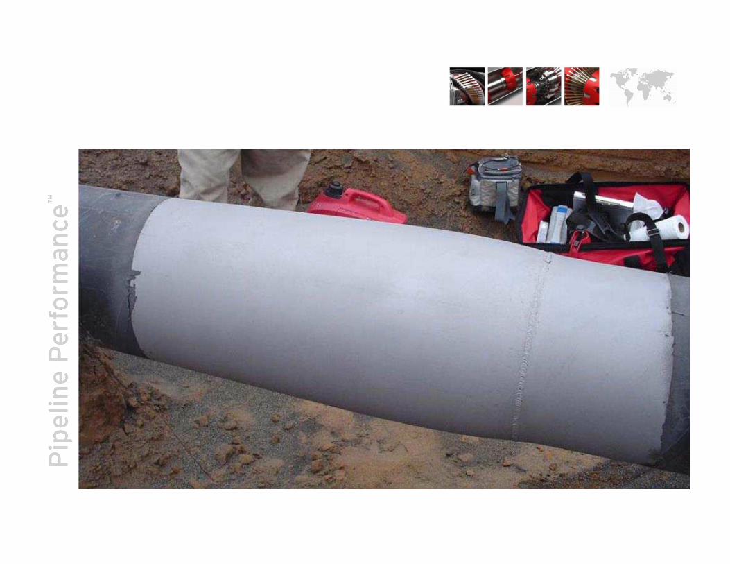
Pipeline Cleaning

Will reduce the intensity of the magnetic signal id entified and will effect data quality. It’s a fundamental mistake to cut the clea ning program short.
MFL tools are the best most effective cleaning tool s in the industry
No One wants an MFL Tool to be a Cleaning Pig!
Sensor “Lift Off”

Your Choice…..ILI Tool Motivation Options
There are various options to meet your needs whether Pumping, Slugging, Pushing or Pulling

Threats

Natural Gas Transmission Failure Causes
Significant Incident Cause Breakdown 20 Year Average (1995 -2014)System Type: GAS TRANSMISSION State: ALL Offshore: ALL

Inline Inspection Technologies

What’s it called ?
aka – “Geo Pig”aka – “ILI”aka – “Smart Pig”aka – “Intelligent Pig”aka – “MFL”aka – “Metal Loss Pig”aka – “UT”aka – “Wall Thickness tool”aka – “Crack Tool”

ILI Technology
LGT (GEO)
KALIPER® 360
Deformation
MFL (SM)
GMFL (FM)
SpirALL
RMFL / LFMFL
XYZ
MDS
SPC
LD GMFL
EMAT
(Light Geometry Tool) 6 - 14”
(Geometry Inspection - NC) 16 - 48”
(Hi Res Geometry Inspection) 4 - 48”
(Axial Magnetic Flux Leakage) 4 - 20”
(Gas Magnetic Flux Leakage) 8 - 48”
(Spiral Magnetic Flux Leakage) 6 - 24”
(Residual / Low Field MFL) 8 - 30”
(IMU – GPS Mapping) 6 - 48”
(DEF/GMFL/SMFL/RMFL/IMU) 6 - 30”
Speed Control (24,26,36,42,48”)
Low Drag Air-coupled Axial MFL
Electro-Magnetic Acoustic Trans 12/16”
(GEO)
(ML)
Versatile
Newest
App Specific

Geometry Inspection
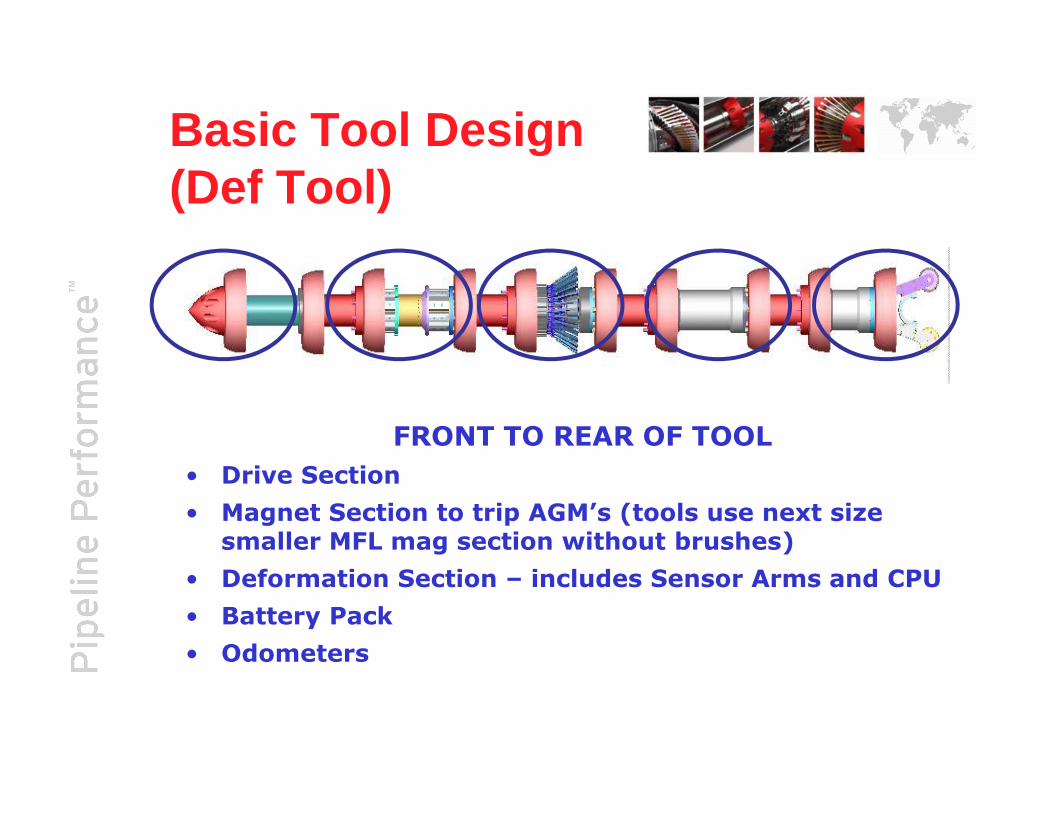
Basic Tool Design (Def Tool)
FRONT TO REAR OF TOOL
• Drive Section
• Magnet Section to trip AGM’s (tools use next size smaller MFL mag section without brushes)
• Deformation Section – includes Sensor Arms and CPU
• Battery Pack
• Odometers

ILI Tool Specs

• Arms ride directly on the pipe wall for greater sensitivity to ID changes
• Circumferential arm spacing approx. 0.25” (6.35mm) when collapsed in ID
• High resolution offers strain capability
Deformation

Deformation

DEF: Expansion
Cross Section at Nominal
Cross Section at Increased ID
DEF: Expansion

Metal Loss Technologies
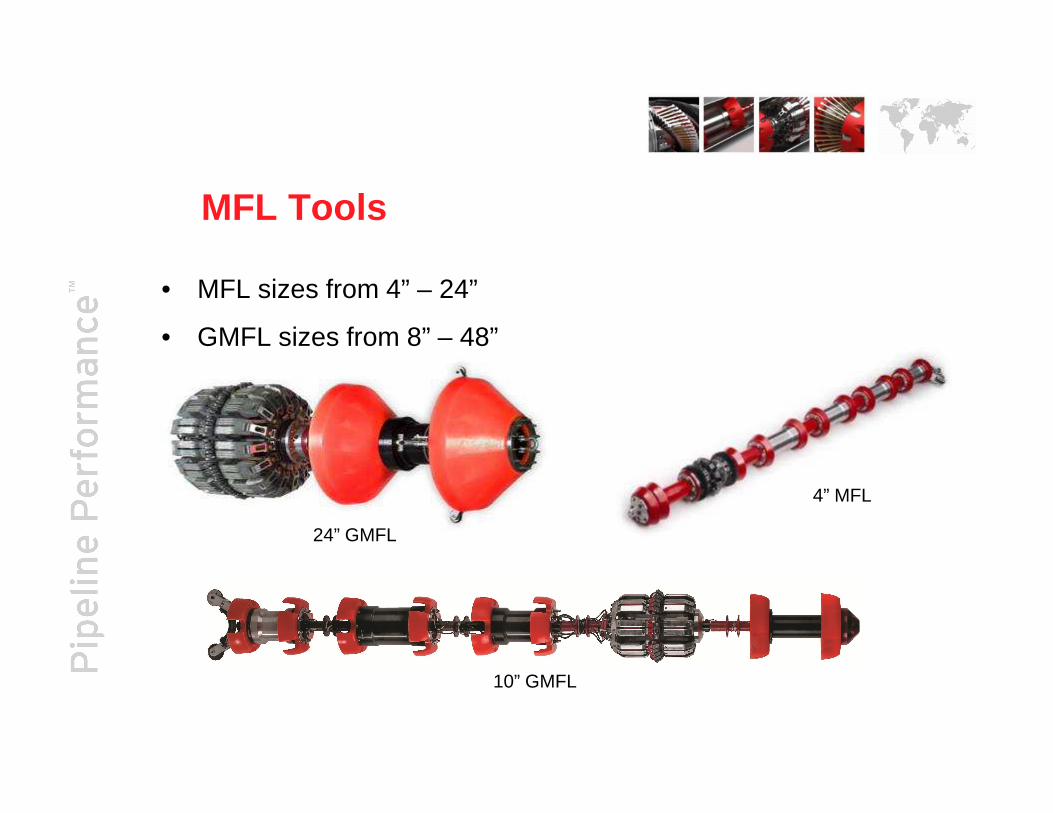
MFL Tools
• MFL sizes from 4” – 24”
• GMFL sizes from 8” – 48”
10” GMFL
4” MFL
24” GMFL

Axial MFL - Principle
Brushes
Magnet
Pipe Wall Section
SNSensor
SNSensor
Brushes
Magnet
Pipe Wall Section
Magnet FluxLeakage
Metal Loss Defect

Chapter HeaderChapter HeaderChapter HeaderChapter Header

Combination Tools
Combination Deformation and MFL IDOD Tool• Combined high resolution
technology• Geometry survey• Metal loss inspection survey• All the data required to assess
a pipelines structural integrity in a single pass.
• Cost effective, saving time and money.

Combination Tools –MFL and Geometry

More Technologies
DEF
LFMSMFL
EMAT
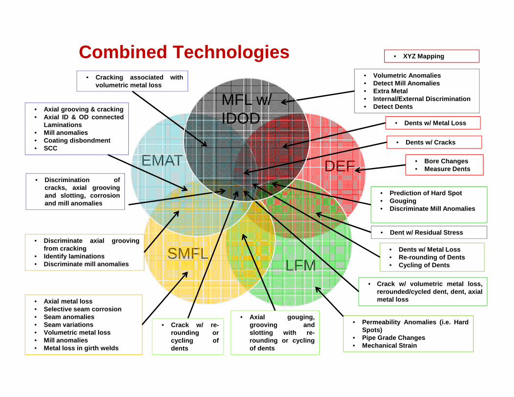
• Axial grooving & cracking• Axial ID & OD connected
Laminations• Mill anomalies• Coating disbondment• SCC
MFL w/IDOD
• Bore Changes• Measure Dents
• Dent w/ Residual Stress
• Permeability Anomalies (i.e. HardSpots)
• Pipe Grade Changes• Mechanical Strain
• Axial gouging,grooving andslotting with re-rounding or cyclingof dents
• Axial metal loss• Selective seam corrosion• Seam anomalies• Seam variations• Volumetric metal loss• Mill anomalies• Metal loss in girth welds
• Dents w/ Metal Loss
• Volumetric Anomalies• Detect Mill Anomalies• Extra Metal• Internal/External Discrimination• Detect Dents
• Dents w/ Metal Loss• Re-rounding of Dents• Cycling of Dents
• Prediction of Hard Spot• Gouging• Discriminate Mill Anomalies
• Cracking associated withvolumetric metal loss
• Discrimination ofcracks, axial groovingand slotting, corrosionand mill anomalies
• Discriminate axial groovingfrom cracking
• Identify laminations• Discriminate mill anomalies
Combined Technologies
• Dents w/ Cracks
• Crack w/ volumetric metal loss,rerounded/cycled dent, dent, axialmetal loss
• Crack w/ re-rounding orcycling ofdents
• XYZ Mapping

0 1 2 3 4 5 6 7 80
1
2
3
4
5
6
7
8
Normalized Defect Length, L/A
Nor
mal
ized
Def
ect
Wid
th,
W/A
Axial Slotting
Axial GroovingPitting
General
Pinhole
Circ
umfe
rent
ial S
lott
ing
Circ
umfe
rent
ial G
roov
ing
Axial MFL
SpirALL® MFL Technology
Overlap = Enhanced Characterization
Axial MFL + SMFL
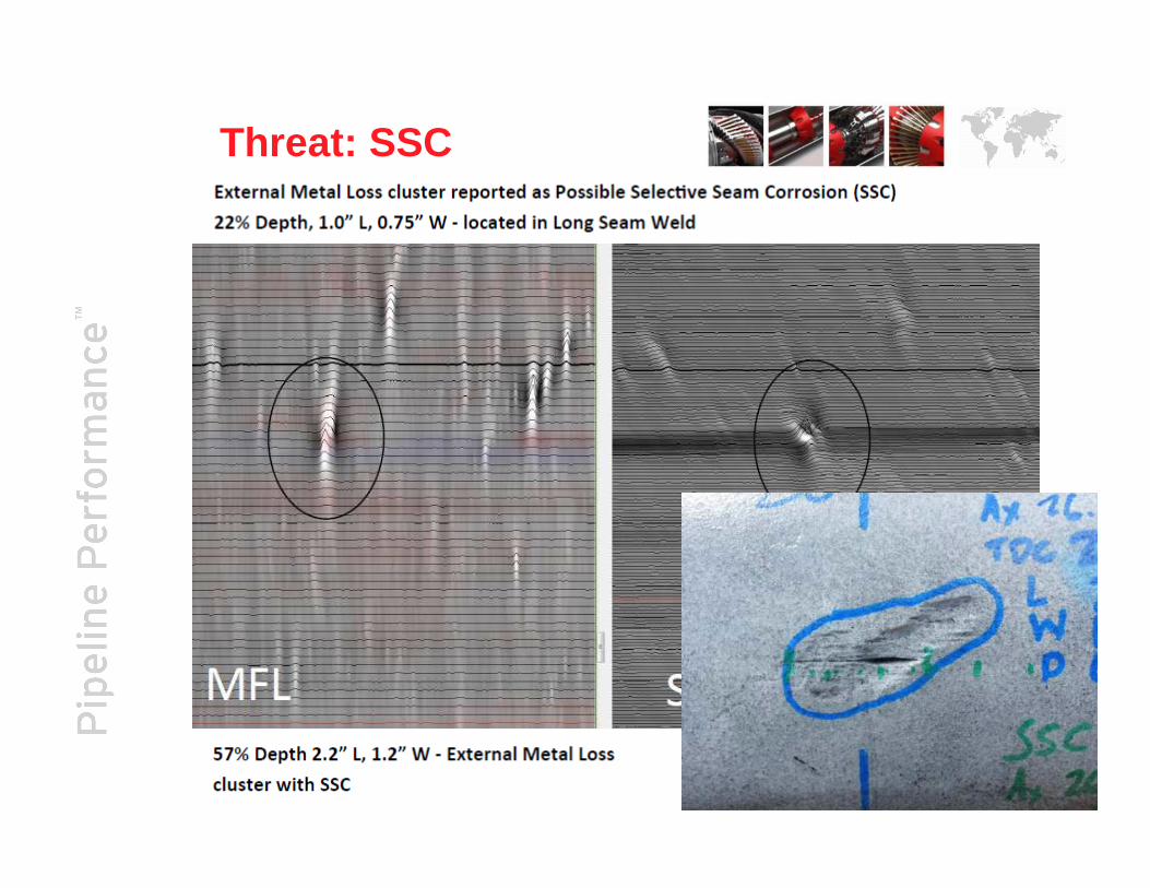
Threat: SSC

MFL SMFL
Anomaly 1
longitudinal seam weld
MFL SMFL
longitudinal seam weld
Anomaly 2
MFL SMFL
longitudinal seam weld
Anomaly 3
# Descr. ILI % Field %
ILI Length(in.)
Field Length (in.)
ILI Width (in.)
Field Width (in.)
1 Planar 37 39 2.22 2.18 0.04 0.01
2 Planar 35 36 1.92 1.22 0.03 0.01
3 Planar 28 35 1.88 2.00 0.06 0.01
Planar / Crack-like Anomalies
Threat: Crack-Like

Metal Loss
Planar Defect –Nothing in MFL
SMFLMFL

MFL SMFL
CharacterizationMetal Loss crossing and within a girth weld

Low Field MFL - Steel Microstructure
Weld Low Carbon
High Carbon Hard Spot
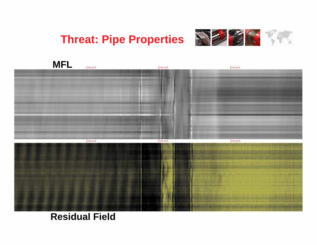
MFL
Residual Field
Threat: Pipe Properties

Threat: Pipe Properties0.188” WT

Re-rounded versus Cycled Dents
Threat: Mech Damage

Re-rounded dent
signature
Cycled dent signature,
notice the strong
“halo” effect
Re-rounded versus Cycled Dents
Threat: Mech Damage

6”
20”
24”
12”
16”
10”8”
30”

Unique Technologies

• Survey / Site Documentation- Centerline
- Depth of Cover
• AGM Selection
• Anomaly Locating
• GPS Mapping
AGM’s“aka” Above Ground Markers
NOTE: If you’re interested in finding anomalies / d efects… this is important
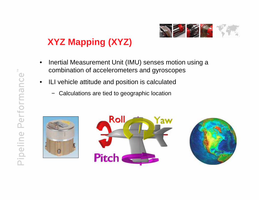
XYZ Mapping (XYZ)
• Inertial Measurement Unit (IMU) senses motion using a combination of accelerometers and gyroscopes
• ILI vehicle attitude and position is calculated
− Calculations are tied to geographic location

XYZ Mapping
Output from high resolution mapping

6” Low Drag Def + MFL Combo
Low Drag, Compact, LightweightUnder 4 feet long
Wheel Mounted Geo Module
Air-CoupledMagnetizer
Centering Brushes
Tool Drive Module ODO’s

Electromagnetic Acoustic Transducer (EMAT)/Ultrason ic Transducer (UT)
EMAT concept
Main Pulse
Wave Propagation
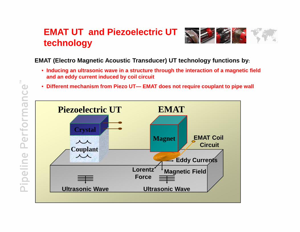
EMAT (Electro Magnetic Acoustic Transducer) UT technology functions by :
• Inducing an ultrasonic wave in a structure through the inter action of a magnetic fieldand an eddy current induced by coil circuit
• Different mechanism from Piezo UT— EMAT does not require cou plant to pipe wall
Piezoelectric UT EMATUT
EMAT Coil Circuit
Ultrasonic WaveUltrasonic Wave
Eddy Currents
LorentzForce
Magnetic Field
Couplant
CrystalMagnet
EMAT UT and Piezoelectric UTtechnology

Piezo-UT
UT angled beam sensors (crack detection scheme)—signals generated at angle
Angled UT sensor heads for crack detection
Angled beam successfullydetecting crack—UT beambounces off crack andreturns to UT sensor
= crack/feature of interest
Couplant—to allow signal topenetrate inspected material
Inspected material

*TDW proprietary sensor arrangement—self-calibrating due to R1 measuring how muchEMAT signal was imparted to the inspected material (signal “ heartbeat”)
Anomalies/cracks causesignal return regardless ofthe alignment
Sensing area
• EMAT transmitters induce signals that travel through the en tire thickness ofinspected material without the need for couplant or angular signals
EMAT signals generated through entire thickness of inspected material—guided shear wave
Xmit Rec1
No couplant required
Inspectedmaterial
Reflected signals
EMAT Overview

www.tdwilliamson.com
® Registered trademarks of T.D. Williamson, Inc. in the United States and in foreign countries. © Copyright 2013
NDE & Positive Material Identification

Equipment
Thickness Meters�Krautkramer DMS 2
�Pipeline, tubes, vessels, tanks in the Oil / Gas and Chemical industries� A Scan and B scan displays
Mag-Particle�Parker AC Portable Yoke
�Wet and Dry Mag-Particle
Dye-Penetrant�Wet water washable dye
�Aerosol developer
Pit Depth Gauges�Farwest Digitial Gauges
�Bridging Bar, Notched feet and Ceramic Magnets hold the unit in place toallow for quick accurate measurements
Multi-Meters�Fluke
�Pipe to Soil�PH Readings
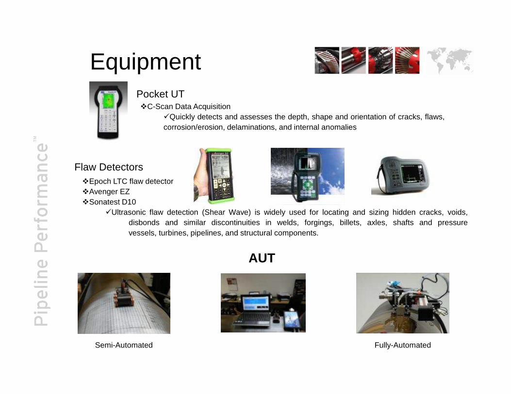
EquipmentPocket UT�C-Scan Data Acquisition
�Quickly detects and assesses the depth, shape and orientation of cracks, flaws,corrosion/erosion, delaminations, and internal anomalies
Flaw Detectors�Epoch LTC flaw detector�Avenger EZ�Sonatest D10
�Ultrasonic flaw detection (Shear Wave) is widely used for locating and sizing hidden cracks, voids,disbonds and similar discontinuities in welds, forgings, billets, axles, shafts and pressurevessels, turbines, pipelines, and structural components.
AUT
Semi-Automated Fully-Automated

Material Preparation Mechanical Properties Assessment
Optical Emissions Spectrometry Magnetic Particle
Proof: NDE (PMI)


Conclusion
• Individual Technologies can be effective when identifying simple features
• Individual technologies have limitations when used independently as defined by NACE SP0102-2010 and API 1160
• Multiple DataSets, is proven to enhance characterization and sizing for complex integrity threats and…• Overcomes limitations of individual technologies• Is better suited for characterization of complex defects• Provides clarity of anomalies, which translates into greater
accuracy• More effectively detects and characterizes crack-like and
metal loss anomalies whether seam or pipe body• Provides comprehensive mechanical damage assessment• Offers foundation for in-situ pipe properties documentation

Questions ?
Related Documents