Literature survey of Direct Sequence Spread Spectrum System (DSSS) Abstract In this literature survey of Direct Sequence Spread Spectrum (DSSS) has been considered as one of the most available digital techniques used for military and public use, taking into consideration the techniques considered by researchers and also considered the benefits which are resistance to intended or unintended jamming, sharing of a single channel among multiple users, reduced signal/background-noise level hampers interception and determination of relative timing between transmitter and receiver, also considered the use of DSSS in underwater acoustic communications. 1. Introduction 1. A Direct Sequence Spread Spectrum (DSSS) This is probably the most widely recognized form of spread spectrum. The DSSS process is performed by effectively multiplying an RF carrier and a pseudo-noise (PN) digital signal. First the PN code is modulated onto the information signal using one of several modulation techniques (eg. BPSK, QPSK, etc ). Then, a doubly balanced mixer is used to multiply the RF carrier and PN modulated information signal. This process causes the RF signal to be replaced with a very wide bandwidth signal with the spectral equivalent of a noise signal. The demodulation process (for the BPSK case) is then simply the mixing/multiplying of the same PN modulated carrier with the incoming RF signal. The output is a signal that is a maximum when the two signals exactly equal one another or are "correlated". The correlated signal is then filtered and sent to a BPSK demodulator. The signals generated with this technique appear as noise in the frequency domain. The wide bandwidth provided by the PN code allows the signal power to drop below the noise threshold without loss of information. The spectral content of an SS signal is shown in Fig. 1. Note that this is just the spectrum of a BPSK signal with a (sin x / x) 2 form.

Welcome message from author
This document is posted to help you gain knowledge. Please leave a comment to let me know what you think about it! Share it to your friends and learn new things together.
Transcript
Literature survey of Direct Sequence Spread Spectrum System (DSSS)
Abstract
In this literature survey of Direct Sequence Spread Spectrum (DSSS) has been considered as one of the most available digital techniques used for military and public use, taking into consideration the techniques considered by researchers and also considered the benefits which are resistance to intended or unintended jamming, sharing of a single channel among multiple users, reduced signal/background-noise level hampers interception and determination of relative timing between transmitter and receiver, also considered the use of DSSS in underwater acoustic communications.
1. Introduction
1. A Direct Sequence Spread Spectrum (DSSS)
This is probably the most widely recognized form of spread spectrum. The DSSS process is performed by effectively multiplying an RF carrier and a pseudo-noise (PN) digital signal. First the PN code is modulated onto the information signal using one of several modulation techniques (eg. BPSK, QPSK, etc ). Then, a doubly balanced mixer is used to multiply the RF carrier and PN modulated information signal. This process causes the RF signal to be replaced with a very wide bandwidth signal with the spectral equivalent of a noise signal. The demodulation process (for the BPSK case) is then simply the mixing/multiplying of the same PN modulated carrier with the incoming RF signal. The output is a signal that is a maximum when the two signals exactly equal one another or are "correlated". The correlated signal is then filtered and sent to a BPSK demodulator.
The signals generated with this technique appear as noise in the frequency domain. The wide bandwidth provided by the PN code allows the signal power to drop below the noise threshold without loss of information. The spectral content of an SS signal is shown in Fig. 1. Note that this is just the spectrum of a BPSK signal with a (sin x / x)2 form.
Fig. 1 BPSK DSSS Spectrum
The bandwidth in DSSS systems is often taken as the null-to-null bandwidth of the main lobe of the power spectral density plot (indicated as 2Rc in Fig. 1). The half power bandwidth of this lobe is 1.2 Rc, where Rc is the chip rate. Therefore, the bandwidth of a DSSS system is a direct function of the chip rate; specifically 2Rc/RINFO. This is just an extension of the previous equation for process gain. It should be noted that the power contained in the main lobe comprises 90 percent of the total power. This allows a narrower RF bandwidth to accommodate the received signal with the effect of rounding the received pulses in the time domain.

One feature of DSSS is that QPSK may be used to increase the data rate. This increase of a factor of two bits per symbol of transmitted information over BPSK causes an equivalent reduction in the available process gain. The process gain is reduced because for a given chip rate, the bandwidth (which sets the process gain) is halved due to the two-fold increase in information transfer. The result is that systems in a spectrally quiet environment benefit from the possible increase in data transfer rate.
Features
1. DSSS phase-modulates a sine wave pseudo randomly with a continuous string of pseudo noise (PN) code symbols called "chips", each of which has a much shorter duration than an information bit. That is, each information bit is modulated by a sequence of much faster chips. Therefore, the chip rate is much higher than the information signal bit rate.
2. DSSS uses a signal structure in which the sequence of chips produced by the transmitter is known a priori by the receiver. The receiver can then use the same PN sequence to counteract the effect of the PN sequence on the received signal in order to reconstruct the information signal.
1. B Transmission method
Direct-sequence spread-spectrum transmissions multiply the data being transmitted by a "noise" signal. This noise signal is a pseudorandom sequence of 1 and −1 values, at a frequency much higher than that of the original signal.
The resulting signal resembles white noise, like an audio recording of "static". However, this noise-like signal can be used to exactly reconstruct the original data at the receiving end, by multiplying it by the same pseudorandom sequence (because 1 × 1 = 1, and −1 × −1 = 1). This process, known as "de-spreading", mathematically constitutes a correlation of the transmitted PN sequence with the PN sequence that the receiver believes the transmitter is using.
The resulting effect of enhancing signal to noise ratio on the channel is called process gain. This effect can be made larger by employing a longer PN sequence and more chips per bit, but physical devices used to generate the PN sequence impose practical limits on attainable processing gain.
If an undesired transmitter transmits on the same channel but with a different PN sequence (or no sequence at all), the de-spreading process results in no processing gain for that signal. This effect is the basis for the code division multiple access (CDMA) property of DSSS, which allows multiple transmitters to share the same channel within the limits of the cross-correlation properties of their PN sequences.
As this description suggests, a plot of the transmitted waveform has a roughly bell-shaped envelope centered on the carrier frequency, just like a normal AM transmission, except that the added noise causes the distribution to be much wider than that of an AM transmission.
In contrast, frequency-hopping spread spectrum pseudo-randomly re-tunes the carrier, instead of adding pseudo-random noise to the data, the latter process resulting in a uniform frequency distribution whose width is determined by the output range of the pseudo-random number generator.
Benefits
Resistance to intended or unintended jamming Sharing of a single channel among multiple users Reduced signal/background-noise level hampers interception Determination of relative timing between transmitter and receiver

Uses
The United States GPS, European Galileo and Russian GLONASS satellite navigation systems
DS-CDMA (Direct-Sequence Code Division Multiple Access) is a multiple access scheme based on DSSS, by spreading the signals from/to different users with different codes. It is the most widely used type of CDMA.
Cordless phones operating in the 900 MHz, 2.4 GHz and 5.8 GHz bands IEEE 802.11b 2.4 GHz Wi-Fi, and its predecessor 802.11-1999. (Their successor 802.11g
uses OFDM instead) Automatic meter reading IEEE 802.15.4 (used, e.g., as PHY and MAC layer for ZigBee, or, as the physical layer for
Wireless HART) Radio-controlled model vehicles
1) Fixed compression scans of DSSS transmitterProfile of DSSS transmitter comprises a main lobe
Figure (2)
2) Swept compression scan of DSSS transmitter

Multiple responses are obtained showing main lobes and side lobes
Figure (3)
3) 3D waterfall graph of DSSS transmitter
Figure (4)
2. Further consideration to Spread Spectrum Communications

CDMA is a form of Direct Sequence Spread Spectrum communications. In general, Spread Spectrum communications is distinguished by three key elements [1]:
1. The signal occupies a bandwidth much greater than that which is necessary to send the information. This results in many benefits, such as immunity to interference and jamming and multi-user access.
2. The bandwidth is spread by means of a code which is independent of the data. The independence of the code distinguishes this from standard modulation schemes in which the data modulation will always spread the spectrum somewhat.
3. The receiver synchronizes to the code to recover the data. The use of an independent code and synchronous reception allows multiple users to access the same frequency band at the same time.
In order to protect the signal, the code used is pseudo-random. It appears random, but is actually deterministic, so that the receiver can reconstruct the code for synchronous detection. This pseudo-
random code is also called pseudo-noise (PN).
Figure (5). Direct Sequence Spread Spectrum System
In Direct Sequence spread spectrum transmission, the user data signal is multiplied by a code sequence. Mostly, binary sequences are used. The duration of an element in the code is called the "chip

time". The ratio between the user symbol time and the chip time is called the spread factor. The transmit signal occupies a bandwidth that equals the spread factor times the bandwidth of the user data [2].
Figure (6): A DS-CDMA signal is generated by multiplication of a user data signal by a code sequence.Source: Jack Glas, T.U. Delft.
In the receiver, the received signal is again multiplied by the same (synchronized) code. This operation removes the code, so we recover the transmitted user data.
Different CDMA users use different codes. In this example the receiver sees the signal from user 1, while the signal from user 2 is heavily attenuated by the correlator (multiplier and integrator) in the receiver.
A CDMA receiver can retrieve the wanted signal by multiplying the receive signal with the same code as the one used during transmission. We find:
∑n=1
N
c12 (n T c+t d )=¿∑
n=1
N
c12 (nT c)=N (1)¿
where c1 is the code sequence used by user 1, Tc is the chip duration, td is a common time offset, shared between transmitter and receiver and N is the length of the code sequence.. Note that the receive code must be perfectly time aligned with the transmit code.
Popular code sequences are:
Maximum length or Pseudo Noise (PN) sequences. Walsh Hadamard Codes. Gold codes, and Kasami codes.

Spreading gain
Figure (7): DS-CDMA signal with a jamming signal.
As dispreading is the same operation as spreading a possible narrowband jammer signal in the radio channel is spread before the detector. Thus, the jam signal is attenuated by the spread factor ("spreading gain").
Near-Far Effect
A major difficulty in Direct Sequence transmission is the Near-Far effect. If more than one user is active, the incoming interference power is suppressed by the cross correlation between the code of the reference user and the code of the interferer. In the event that the interferer is closer to the receiver then the reference user, the interference components may not be sufficiently attenuated by the despreading process. In cellular CDMA systems, (adaptive) power control is needed to avoid this problem

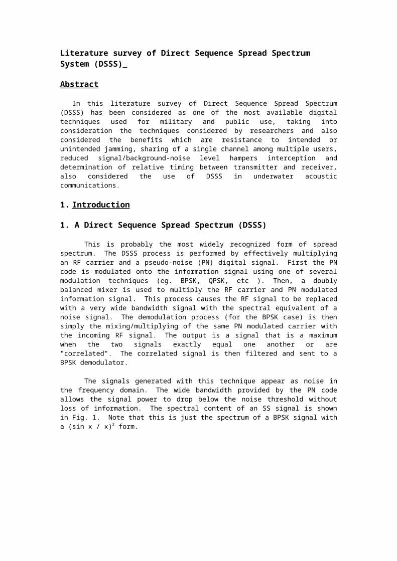
Inherent Diversity
In a multipath fading channel, delayed reflections interfere with the direct signal. However, a DS-CDMA signal suffering from multipath dispersion can be detected by a rake receiver. This receiver optimally combines signals received over multiple paths.
.
Fig. (8) CDMA Block Diagram.
Different reflected waves arrive with different delays. A rake receiver can detect these different signals separately. These signals are then combined, using the diversity technique called maximum ratio combining.
Multipath self-interference is attenuated, because one can choose codes such that
∑n=1
N
c1 (n T c) c1 (n T c+t d )≅ 0(2)
Typical applications for the resulting short-range data transceivers include satellite-positioning systems (GPS), 3G mobile telecommunications, W-LAN (IEEE® 802.11a, IEEE 802.11b, IEEE 802.11g), and Bluetooth®. Spread-spectrum techniques also aid in the endless race between communication needs and radio-frequency availability—situations where the radio spectrum is limited and is, therefore, an expensive resource.
3. Underwater Acoustic Communication from sight of DSSS
CODE-DIVISION multiple-access communication (CDMA) is an important emerging technology for underwater acoustic networks for both civilian and military purposes. CDMA permits random, overlapping access to a shared communication channel as required in an autonomous ocean-

sampling network (AOSN) scenario. Drawing from the results in RF wireless communications, two code-division spread-spectrum signaling methods are proposed for simultaneous-access communication: phase-modulated, direct-sequence spread-spectrum (DSSS) signaling, and non-coherent frequency-hopped spread-spectrum (FHSS). DSSS uses phase-shift keying and spreads the data using codes with good auto- and cross-correlation properties, while FHSS methods utilize many frequency bands with hopping patterns chosen for minimum interference between users. While both of these techniques may be suitable for use in the underwater acoustic channel, the best choice depends upon the characteristics of the particular propagation conditions, specifically time and frequency spread. Additional considerations include the desired throughput, total transducer bandwidth, and the computational resources available at the receiver. Multiuser underwater acoustic communication is one of the enabling technologies for the autonomous ocean-sampling network (AOSN). Multiuser communication allows vehicles, moorings, and bottom instruments to interact without human intervention to perform adaptive sampling tasks. In addition, multiuser communication may be used to send data from many autonomous users to one buoy with RF communications capability, which will then forward the information to shore. The two major signaling techniques for multiuser acoustic communication are phase-shift keying (PSK) direct-sequence spread-spectrum (DSSS) and frequency-shift keying (FSK) frequency-hopped spread-spectrum (FHSS). Selecting between these two techniques requires not only a study of their performance under multiuser conditions, but also an analysis of the impact of the underwater acoustic channel. In the case of DSSS, limitations in temporal coherence of the channel affect the maximum spreading factor, leading to situations that may be better suited to FHSS signals.
Conversely, the multipath resolving properties of DSSS minimize the effects of frequency-selective fading that degrade the performance of FSK modulation. Two direct-sequence receivers potentially suitable for the underwater channel are presented. The first utilizes standard dispreading followed by decision-directed gain and phase tracking. The second uses chip-rate adaptive filtering and phase tracking prior to dispreading. Results from shallow water testing in two different scenarios are presented to illustrate the techniques and their performance [3].
Precise estimation of spatial range underwater is important for a variety of underwater applications: positioning and navigation (long baseline and short baseline positioning); physical oceanography (tomography); and marine geology (geodesy). Range estimates are typically obtained by observing one-way or two-way acoustic travel
times. Since the ocean environment is opaque to most conventional electromagnetic signals, acoustic signals are the preferred method for making range measurements. Acoustic signals are not perfect, however, and are still limited by the dynamics of the underwater channel—specifically multipath and fading . Direct sequence spread-spectrum (DSSS) signal processing has many advantages over continuous wave techniques for time-of-flight range estimation:
improved precision, extended effective range, robustness to ambient or jamming noise, increased update rate, and simultaneous multi-user capability.
Design of appropriate DSSS codes requires matching the code parameters to the acoustic operating environment to maximize system performance. We consider three canonical ocean environments:a laboratory test-tank, the littoral zone, and the deep water channel. The characteristics of these acoustic channel models directly influence the code design to maximize range estimate performance. We parameterize the design choices for DSSS codes by code type, code length, carrier frequency, and chip rate [4].
References[1] Michael Hendry, "Introduction to CDMA", This paper provides an introduction to Code Division Multiple Access (CDMA) communications, covering a Radio Carrier Station (RCS) and a Fixed Subscriber Unit (FSU).[2] Jack Glas, T.U. Delft. www.WirelessCommunication.NL[3] Lee Freitag, Milica Stojanovic, Sandipa Singh, and Mark Johnson,"Analysis of Channel Effects on Direct-Sequence and Frequency-Hopped Spread-Spectrum Acoustic Communication", IEEE JOURNAL OF OCEANIC ENGINEERING, VOL. 26, NO. 4, OCTOBER 2001.[4] Brian Bingham, Ballard Blair and David Mindell, "On the Design of Direct Sequence Spread-Spectrum Signaling for Range Estimation"
Related Documents