Welcome message from author
This document is posted to help you gain knowledge. Please leave a comment to let me know what you think about it! Share it to your friends and learn new things together.
Transcript


Dear Aksa Generating Set Users;
First of all, we would like to thank you for your choice of Aksa Generating Set.
It is solid, safe and reliable machine, built according to the latest technology.
This maintenance and user manual is designed and developed to make you familiar
with the generating system.
Please read the following instructions carefully before starting to use your machine.
This manual gives general information about mounting, of the generating set.
Tables and diagrams are also available outlining your generating set.
Never operate, maintain or repair your generating set without taking general safety precautions.
Aksa Jeneratör does not assume responsibility for possible errors.
Aksa Jeneratör reserves to make changes without prior notice.
1. INTRODUCTION................................................................................................................................................................ 12. GENERAL SAFETY PRECAUTIONS ............................................................................................................................... 22.1. General..................................................................................................................................................................................... 2
2.2. Handling ................................................................................................................................................................................... 22.3. Fire and Explosion .................................................................................................................................................................. 22.4. Mechanical ............................................................................................................................................................................... 32.5. Chemical .................................................................................................................................................................................. 32.6. Noise ........................................................................................................................................................................................ 32.7. Electrical ................................................................................................................................................................................... 32.8. First Aid for Electric Shock ................................................................................................................................................... 43. GENERAL DESCR‹PT‹ON ................................................................................................................................................. 53.1. Generating Set Description and Identification .................................................................................................................. 53.2. Generating Set Main Parts .................................................................................................................................................... 53.3. Diesel engine........................................................................................................................................................................... 63.4. Engine Electrical System ........................................................................................................................................................ 63.5. Cooling System....................................................................................................................................................................... 6
3.6. Synchronous Alternator ........................................................................................................................................................ 63.7. Coupling................................................................................................................................................................................... 63.8. Fuel Tank and Base Frame .................................................................................................................................................... 63.9. Vibration Isolation .................................................................................................................................................................. 63.10. Silencer and Exhaust System ................................................................................................................................................ 63.11. Control System....................................................................................................................................................................... 74. ELECTRIC STARTING SYSTEM ....................................................................................................................................... 74.1. Battery Systems ...................................................................................................................................................................... 74.2. Maintenance Batteries ........................................................................................................................................................... 74.3. Battery Maintenance .............................................................................................................................................................. 74.4. Maintenance Free Batteries .................................................................................................................................................. 74.5. Control of the Battery ........................................................................................................................................................... 74.6. Starting Aids ............................................................................................................................................................................ 7
5. HEALTY and SAFETY .......................................................................................................................................................... 75.1. Fire Protection ........................................................................................................................................................................ 75.2. Exhaust Gases ......................................................................................................................................................................... 85.3. Moving Parts............................................................................................................................................................................ 85.4. Hazardous Voltages ............................................................................................................................................................... 85.5. Water ....................................................................................................................................................................................... 85.6. Coolant and Fuel .................................................................................................................................................................... 86. GENERAL PRECAUTIONS AND CONTROLS WHICH MUST BE DONE
AFTER STARTING UP THE GENERATING SET......................................................................................................... 97. GENERATING SET CONTROL SYSTEM...................................................................................................................... 97.1. Control Panels ........................................................................................................................................................................ 97.1.1. Control System P 72 Panel Specifications ......................................................................................................................... 97.1.3. Static Battery Trickle Charger ..............................................................................................................................................107.2. Control System Options.......................................................................................................................................................10
7.2.1. Heaters.....................................................................................................................................................................................10

8. GENERAL PRECAUTIONS AND CONTROLS WHICH MUST BE DONE AFTER STARTING UPTHE GENERATING SET.....................................................................................................................................................10
9. LUBRICATING OIL .............................................................................................................................................................109.1. Oil Performance Properties .................................................................................................................................................10
9.2. Lubrication oil Recommendations for Lister-Petter engines ..........................................................................................109.3. Oil Viscosity.............................................................................................................................................................................119.4. Oil and Filter Changes ...........................................................................................................................................................1110. GENERATING SET MAINTENANCE.............................................................................................................................1211. ENGINE TROUBLESHOOTING......................................................................................................................................1512. ALTERNATOR DESCR‹PT‹ON........................................................................................................................................1612.1. General.....................................................................................................................................................................................1612.2. Construction and Components...........................................................................................................................................1612.3. Operation ................................................................................................................................................................................1612.4. Automatic Voltage Regulator...............................................................................................................................................1612.5. Insulation Test.........................................................................................................................................................................1613. MECCALTE ALTERNATOR TROUBLESHOOTING .................................................................................................1714. STORAGE...............................................................................................................................................................................1714.1. Storage .....................................................................................................................................................................................17
14.2. Alternator Storage .................................................................................................................................................................1814.3. Battery Storage .......................................................................................................................................................................1814.4. Preparing for operation after storage .................................................................................................................................1815. GENERAL PRECAUTIONS A BOUT WARRANTY...................................................................................................18
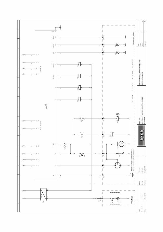
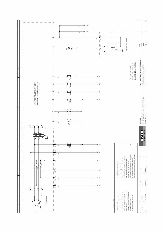
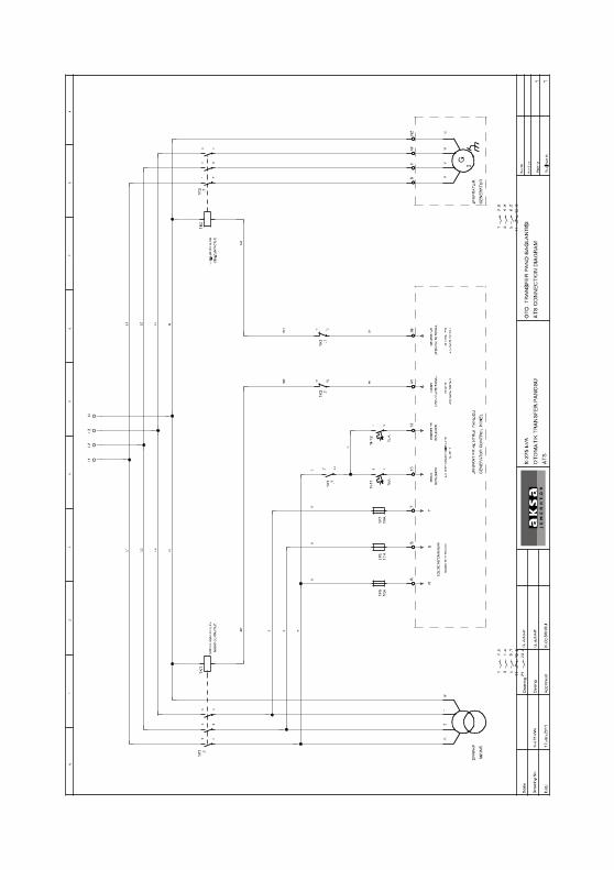
CONTROL PANELS WIRING DIAGRAM....................................................................................................................18

1. INTRODUCTIONAksa Generating set is designed to be commissioned, whendelivered, as soon as the necessary cooling water, antifreeze,fuel, lubrication oil and fully charged battery are provided.With its long years of experience, Aksa manufactures efficient,reliable and quality generating set.This operating and maintenance manual is prepared to assistthe operator in operation and maintenance of the generatingset. Observing the advices and rules in this manual will ensurethat the generating set operates in maximum performanceand efficiency for a long time.
- Care should be taken to perform more frequent maintenancein dirty and dusty environments in order to keep the generatingset in good working condition.
- Necessary adjustment and repairs should be made only byauthorized and qualified persons.
- Each generating set has a model and a serial number indicatedon a label on the base frame. This plate also indicates themanufacturing date, voltage, current, power in kVA and kW,frequency, power factor and weight of the generating set.These datas are necessary in spare part orders, for warrantyvalidity and for service calls.
The generating set is designed to be safe when used in correctmanner. However responsibility for safety rests with thepersonnel who install, use and maintain the set. If the followingsafety precautions are followed, the possibility of accidents willbe minimized. Before performing any procedure or operatingtechnique, it is up to the user to ensure that it is safe. Thegenerating set should only be operated by personnel who areauthorized and trained.
Only people that have the right skills should be allowed tooperate, adjust, perform maintenance or repair on AksaJeneratör equipment. It is the responsibility of management toappoint operators with the appropriate training and skill foreach category of job.
Skill level1: Operator An operator is trained in all aspects of operating the unit withthe push- buttons, and trained to know the safety aspects.
Skill level 2: Mechanical technicianA mechanical technician is trained to operate the unit thesame as the operator. In addition, the mechanical technicianis also trained to perform maintenance and repair, as describein the instruction manual, and is allowed to change settings ofthe control and safety system. A mechanical technician doesnot work on live electrical components.
Skill level 3: Electrical technicianAn electrical technician and has the same qualifications as boththe operator and the mechanical technician. In addition, theelectrical technician may carry out electrical repairs within thevarious enclosures of the unit. This includes work on liveelectrical components.
Skill level 4: Specia list from the manufacturerThis is skilled specialist sent by the manufacturer or its agentto perform complex repairs or modifications to the equipment.In general it is recommended that not more than two peopleoperate the unit, more operators could lead to un safe operatingconditions. Take necessary steps to keep unauthorized personaway from the unit and eliminate all possible source of dangerat the unit.The manufacturer does not accept any liability for any damagearising from the use of non-original parts and for modifications,additions or conversions made without the manufacturer’sapproval in writing.
1
2. GENERAL SAFETY PRECAUTIONS
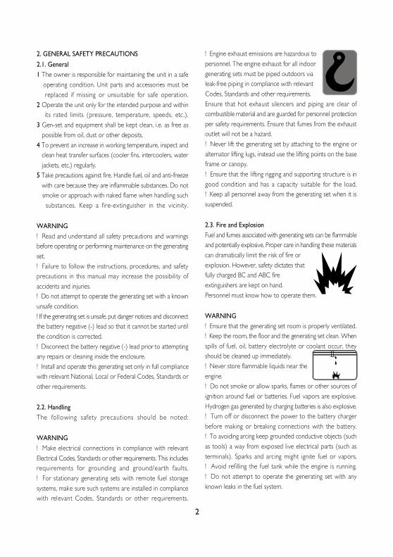
2.1. General1 The owner is responsible for maintaining the unit in a safe operating condition. Unit parts and accessories must be replaced if missing or unsuitable for safe operation.2 Operate the unit only for the intended purpose and within its rated limits (pressure, temperature, speeds, etc.).3 Gen-set and equipment shall be kept clean, i.e. as free as possible from oil, dust or other deposits.4 To prevent an increase in working temperature, inspect and clean heat transfer surfaces (cooler fins, intercoolers, water jackets, etc.) regularly.5 Take precautions against fire. Handle fuel, oil and anti-freeze with care because they are inflammable substances. Do not smoke or approach with naked flame when handling such substances. Keep a fire-extinguisher in the vicinity.
WARNING! Read and understand all safety precautions and warningsbefore operating or performing maintenance on the generatingset.! Failure to follow the instructions, procedures, and safetyprecautions in this manual may increase the possibility ofaccidents and injuries.! Do not attempt to operate the generating set with a knownunsafe condition.! If the generating set is unsafe, put danger notices and disconnectthe battery negative (-) lead so that it cannot be started untilthe condition is corrected.! Disconnect the battery negative (-) lead prior to attemptingany repairs or cleaning inside the enclosure.! Install and operate this generating set only in full compliancewith relevant National, Local or Federal Codes, Standards orother requirements.
2.2. HandlingThe following safety precaut ions should be noted:
WARNING! Make electrical connections in compliance with relevantElectrical Codes, Standards or other requirements. This includesrequirements for grounding and ground/earth faults.! For stationary generating sets with remote fuel storagesystems, make sure such systems are installed in compliancewith relevant Codes, Standards or other requirements.
! Engine exhaust emissions are hazardous topersonnel. The engine exhaust for all indoorgenerating sets must be piped outdoors vialeak-free piping in compliance with relevantCodes, Standards and other requirements.Ensure that hot exhaust silencers and piping are clear ofcombustible material and are guarded for personnel protectionper safety requirements. Ensure that fumes from the exhaustoutlet will not be a hazard.! Never lift the generating set by attaching to the engine oralternator lifting lugs, instead use the lifting points on the baseframe or canopy.! Ensure that the lifting rigging and supporting structure is ingood condition and has a capacity suitable for the load.! Keep all personnel away from the generating set when it issuspended.
2.3. Fire and ExplosionFuel and fumes associated with generating sets can be flammableand potentially explosive. Proper care in handling these materialscan dramatically limit the risk of fire orexplosion. However, safety dictates thatfully charged BC and ABC fireextinguishers are kept on hand.Personnel must know how to operate them.
WARNING! Ensure that the generating set room is properly ventilated.! Keep the room, the floor and the generating set clean. Whenspills of fuel, oil, battery electrolyte or coolant occur, theyshould be cleaned up immediately.! Never store flammable liquids near theengine.! Do not smoke or allow sparks, flames or other sources ofignition around fuel or batteries. Fuel vapors are explosive.Hydrogen gas generated by charging batteries is also explosive.! Turn off or disconnect the power to the battery chargerbefore making or breaking connections with the battery.! To avoiding arcing keep grounded conductive objects (suchas tools) a way from exposed live electrical parts (such asterminals). Sparks and arcing might ignite fuel or vapors.! Avoid refilling the fuel tank while the engine is running.! Do not attempt to operate the generating set with anyknown leaks in the fuel system.
2
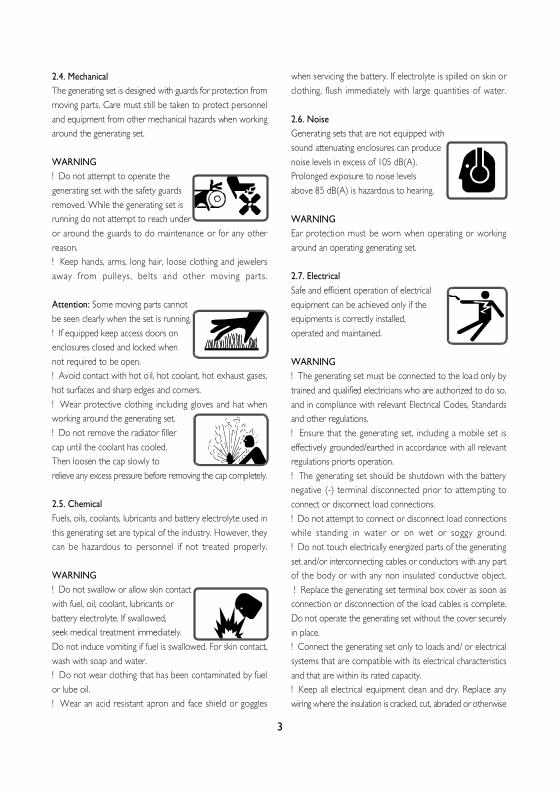
2.4. MechanicalThe generating set is designed with guards for protection frommoving parts. Care must still be taken to protect personneland equipment from other mechanical hazards when workingaround the generating set.
WARNING! Do not attempt to operate thegenerating set with the safety guardsremoved. While the generating set isrunning do not attempt to reach underor around the guards to do maintenance or for any otherreason.! Keep hands, arms, long hair, loose clothing and jewelersaway from pulleys, belts and other moving parts.
Attention: Some moving parts cannotbe seen clearly when the set is running.! If equipped keep access doors onenclosures closed and locked whennot required to be open.! Avoid contact with hot oil, hot coolant, hot exhaust gases,hot surfaces and sharp edges and corners.! Wear protective clothing including gloves and hat whenworking around the generating set.! Do not remove the radiator fillercap until the coolant has cooled.Then loosen the cap slowly torelieve any excess pressure before removing the cap completely.
2.5. ChemicalFuels, oils, coolants, lubricants and battery electrolyte used inthis generating set are typical of the industry. However, theycan be hazardous to personnel if not treated properly.
WARNING! Do not swallow or allow skin contactwith fuel, oil, coolant, lubricants orbattery electrolyte. If swallowed,seek medical treatment immediately.Do not induce vomiting if fuel is swallowed. For skin contact,wash with soap and water.! Do not wear clothing that has been contaminated by fuelor lube oil.! Wear an acid resistant apron and face shield or goggles
when servicing the battery. If electrolyte is spilled on skin orclothing, flush immediately with large quantities of water.
2.6. NoiseGenerating sets that are not equipped withsound attenuating enclosures can producenoise levels in excess of 105 dB(A).Prolonged exposure to noise levelsabove 85 dB(A) is hazardous to hearing.
WARNINGEar protection must be worn when operating or workingaround an operating generating set.
2.7. ElectricalSafe and efficient operation of electricalequipment can be achieved only if theequipments is correctly installed,operated and maintained.
WARNING! The generating set must be connected to the load only bytrained and qualified electricians who are authorized to do so,and in compliance with relevant Electrical Codes, Standardsand other regulations.! Ensure that the generating set, including a mobile set iseffectively grounded/earthed in accordance with all relevantregulations priorts operation.! The generating set should be shutdown with the batterynegative (-) terminal disconnected prior to attempting toconnect or disconnect load connections.! Do not attempt to connect or disconnect load connectionswhile standing in water or on wet or soggy ground.! Do not touch electrically energized parts of the generatingset and/or interconnecting cables or conductors with any partof the body or with any non insulated conductive object. ! Replace the generating set terminal box cover as soon asconnection or disconnection of the load cables is complete.Do not operate the generating set without the cover securelyin place.! Connect the generating set only to loads and/ or electricalsystems that are compatible with its electrical characteristicsand that are within its rated capacity.! Keep all electrical equipment clean and dry. Replace anywiring where the insulation is cracked, cut, abraded or otherwise
3
degraded. Replace terminals that are worn, discolored orcorroded. Keep terminals clean and tight.! Insulate all connections and disconnected wires.! Use only Class BC or Class ABC extinguishers on electricalfires.
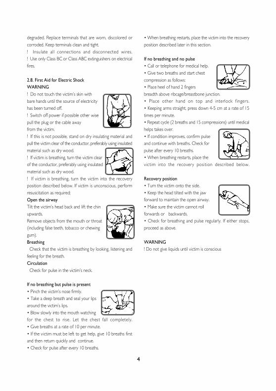
2.8. First Aid for Electric ShockWARNING! Do not touch the victim’s skin withbare hands until the source of electricityhas been turned off.! Switch off power if possible other wisepull the plug or the cable awayfrom the victim.! If this is not possible, stand on dry insulating material andpull the victim clear of the conductor, preferably using insulatedmaterial such as dry wood.! If victim is breathing, turn the victim clearof the conductor, preferably using insulatedmaterial such as dry wood.! If victim is breathing, turn the victim into the recoveryposition described below. If victim is unconscious, performresuscitation as required;Open the airwayTilt the victim’s head back and lift the chinupwards.Remove objects from the mouth or throat(including false teeth, tobacco or chewinggum).Breathing Check that the victim is breathing by looking, listening andfeeling for the breath.Circulation Check for pulse in the victim’s neck.
If no breathing but pulse is present• Pinch the victim’s nose firmly.• Take a deep breath and seal your lipsaround the victim’s lips.• Blow slowly into the mouth watchingfor the chest to rise. Let the chest fall completely.• Give breaths at a rate of 10 per minute.• If the victim must be left to get help, give 10 breaths firstand then return quickly and continue.• Check for pulse after every 10 breaths.
• When breathing restarts, place the victim into the recoveryposition described later in this section.
If no breathing and no pulse• Call or telephone for medical help.• Give two breaths and start chestcompression as follows:• Place heel of hand 2 fingersbreadth above ribcage/breastbone junction.• Place other hand on top and interlock f ingers.• Keeping arms straight, press down 4-5 cm at a rate of 15times per minute.• Repeat cycle (2 breaths and 15 compressions) until medicalhelps takes over.• If condition improves, confirm pulseand continue with breaths. Check forpulse after every 10 breaths.• When breathing restarts, place thevictim into the recovery position described below.
Recovery position• Turn the victim onto the side.• Keep the head tilted with the jawforward to maintain the open airway.• Make sure the victim cannot rollforwards or backwards.• Check for breathing and pulse regularly. If either stops,proceed as above.
WARNING! Do not give liquids until victim is conscious
4
3. GENERAL DECRIPTION3.1. Generating Set Description and IdentificationDiesel –electric generating sets are independent units for theproduction of electric power; basically, they comprise a constantvoltage synchronous generator driven by an internal–combustion, diesel –cycle engine.The sets are used for two main purposes:
a- Continuous duty sets,Used to produce electric power for countless requirements(motive power, lighting, heating, etc) inareas where other sources or power are unavailable.
b- Emergency duty sets,Used during public network failures, when such failures areliable to cause serious trouble to persons or material or financialdamage (i.e. in hospitals, industrial plants with non-stop operatingcyc les , etc) or to meet peak energy demands.According to their application, the sets are further dividedinto:- set for use on land- set for use at seaThe sets for use on land can be either:- stationary sets (fixed installation), or- mobile sets (mobile installation)These two types of sets are available in a vast range of versions,for every operating requirement, the main ones being:01. hand control generating sets02. stand-by generating sets
The standard stat ionary generating set comprises:- diesel engine- synchronous generator- coupling- metal sub-base with vibration isolators- starter batteries- fuel tank within the bed-plate- instrument panel- exhaust gas silencer.
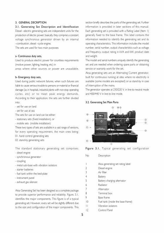
Aksa Generating Set has been designed as a complete packageto provide superior performance and reliability. Figure. 3.1.identifies the major components. This figure is of a typicalgenerating set. However, every set will be slightly different dueto the size and configuration of the major components. This
section briefly describes the parts of the generating set. Furtherinformation is provided in later sections of this manual.Each generating set is provided with a Rating Label (Item 1)generally fixed to the base frame. This label contains theinformation needed to identify the generating set and itsoperating characteristics. This information includes the modelnumber, serial number, output characteristics such as voltageand frequency, output rating in kVA and kW, product dateand weight.The model and serial numbers uniquely identify the generatingset and are needed when ordering spare parts or obtainingservice or warranty work for the set.Aksa generating sets are an Alternating Current generator,built for continuous running at sites where no electricity isavailable (some models are excepted) or as stand-by in caseof interruption of the mains.The generator operates at 230/220 V. in line-to-neutral modeand 400/440 V in line-to-line mode.
3.2. Generating Set Main Parts
Figure 3 .1 . Typical generat ing set conf igurat ion
No Description
1 Aksa generating set rating label2 Diesel engine3 Air filter4 Battery5 Battery charging alternator6 Radiator7 Alternator8 Terminal box9 Base frame10 Fuel tank (inside the base frame)11 Vibration isolators12 Control Panel
5
12
8
7
1
3 10 2
5
6
11
9
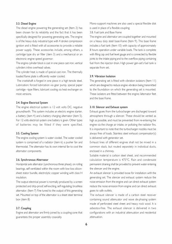
3.3. Diesel EngineThe diesel engine powering the generating set (Item 2) hasbeen chosen for its reliability and the fact that it has beenspecifically designed for powering generating sets. The engineis of the heavy duty industrial type with 4 stroke compressionignition and is fitted with all accessories to provide a reliablepower supply. These accessories include, among others, acartridge type dry air filter (item 3) and a mechanical or anelectronic engine speed governor.The engine cylinder block is cast in one piece cast iron, verticalcylinders inline overhead valves.The cylinder heat is made of special cast iron. The thermallyloaded flame plate is efficiently water cooled. The crankshaft is forged in one piece in a high tensile steel.Lubrication: forced lubrication via gear pump, special papercartridge –type filters, lubricant cooling via heat exchanger onmost versions.
3.4. Engine Electrical SystemThe engine electrical system is 12 volt volts DC, negativeground/earth. This system includes an electric engine starter,a battery (item 4) and a battery charging alternator (item 5).For 12 volts electrical system one battery is given. Other typesof batteries may be fitted if they were specif ied.
3.5. Cooling SystemThe engine cooling system is water cooled. The water cooledsystem is comprised of a radiator (item 6) a pusher fan andthermostat. The alternator has its own internal fan to cool thealternator components.
3.6. Synchronous AlternatorHorizontal axle alternator (synchronous three phase), on rollingbearings, self-ventilated within the room with low-loss silicon-sheet stator bundle, electrolytic copper winding with class Hinsulation.The output electrical power is normally produced by a screenprotected and drip-proof, self-exciting, self regulating, brushlessalternator. (Item 7) Fine tuned to the output of this generatingset. Mounted on top of the alternator is a sheet steel terminalbox (item 8)
3.7. CouplingEngine and alternator are firmly joined by a coupling cone thatguarantees the proper assembly coaxiality
Mono-support machines are also used a special flexible diskis used in place of a flexible coupling.3.8. Fuel tank and Base frameThe engine and alternator are coupled together and mountedon a heavy duty steel base-frame (Item 9). This base frameincludes a fuel tank (Item 10) with capacity of approximately8 hours operation under variable loads. The tank is completewith filling cap and fuel level gauge and is connected by flexiblejoints to the intake piping and to the overflow piping containingfuel from the injector drain. High power gen-set’s fuel tank isseparate from set.
3.9. Vibration IsolationThe generating set is fitted with vibration isolators (Item 11)which are designed to reduce engine vibration being transmittedto the foundation on which the generating set is mounted.These isolators are fitted between the engine /alternator feetand the base frame.
3.10. Silencer and Exhaust systemExhaust gases from the turbocharger are discharged towardatmosphere through a silencer. These should be vented ashigh as possible, and must be prevented from re-entering theengine via the charge air intake, or polluting the radiator fins.It is important to note that the turbocharger nozzles must bealways free of loads. Stainless steel exhaust compensator(s)is delivered with generator set.Exhaust lines of different engines shall not be mixed in acommon stack, but routed separately in individual ducts,enclosed in a chimney.Suitable material is carbon steel sheet, and recommendedcalculation temperature is 475°C. Rain and condensatepermanent draining shall be provided to prevent water enteringthe silencer and the engine.An exhaust silencer is provided loose for installation with thegenerating set. The silencer and exhaust system reduce thenoise emission from the engine and can direct exhaust systemreduce the noise emission from engine and can direct exhaustgases to safe outlets.The exhaust silencer is made of a carbon steel receivercontaining sound attenuator and wave de-phasing systemmade of perforated steel sheet and heavy rock wool. It isasbestos-free. The exhaust silencer is delivered in twoconfigurations with an industrial attenuation and residentialattenuation.
6
3.11. Control SystemOne of several types of control systems and panels (item 12)may be fitted to control the operation and output of the setand to protect the set from possible malfunctions. Section 11of this manual provides detailed information on these systemsand will aid in identification of the control system fitted on thegenerating set.
4. ELECTRIC START‹NG SYSTEMSElectric starting systems are generally used on all gen-sets.The power source for electric starting systems is a 12 VDCbattery system. Control of starting is via a start solenoid whichis controlled by the gen-set control system.
4.1. Battery SystemsBattery type is lead acid. Lead acid batteries are generally used,being the least expensive.
4.2. Maintenance BatteriesWarning- Do not smoke or allow sparks, flames or other sources ofignition around batteries. Hydrogen gas generated by chargingbatteries is explosive.- Wear an acid resistant apron and face shield or goggles whenservicing the battery. If electrolyte is spilled on skin or clothing,f lush immediately with large quantit ies of water.- Take out the metallic things in your wrist and protect yourwrist and hand.- Disconnect the battery negative (earth) lead first and reconnectlast.- Always ensure that battery charging is carried out in a wellventilated area.The starting batteries should be located as close as possibleto the generating set while still being accessible for servicing.This will prevent electrical losses
4.3. Battery Maintenance• Keep the top of the battery and its terminals clean.• Cover the battery terminals and its connections with Vaseline.• Tighten the terminals but not t ighten it hardly.• Control the electrolyte level periodically. It must be 10 mmabove the plates.• Control the abrasion in the charge alternator belt and checkperiodically the belt tension according to producer’recommendation.• Ensure that your battery is not uncharged.
4.4. Maintenance Free BatteriesEnsure that all battery connections are correct and batteriesare always charged. After that there is not any procedure forthis batteries.
4.5. Control of the BatteryConduct an inspection every time before testing the battery.1. A white powdered element causes abrasion to the pole-heads, its connections. Remove the connections and washthem with hot water to purify the oxidation. Reconnect it andcoat with vaseline.2. Check if any un-t ightened connect ions exist .
4.6. Starting AidsIt is customary to maintain coolant temperatures above 40°Cmin. to promote quick starting on an emergency generatingset and to take the load. Thermostatically controlled immersionheaters, deriving their supply from the primary source of powerare fitted in the engine cooling system to provide this heating.Heater warms up the jacket water of the engine when thegenerating set is not working.
5. HEALTY and SAFETYSafety should be the primary concern of the facility designengineer and all personnel engaged on installation andcommissioning. Safety involves two aspects:1) Safe operation of the generator itself (and its accessories).2) Reliable operation of the system.Reliable operation of the system is related to safety becauseequipment affecting life and health, such as life supportequipment in hospitals, emergency aggress lighting, buildingventilators, elevators and fire pumps, may depend on thegenerator set.
5.1. Fire ProtectionThe design, selection and installation of fire protection systemsrequire the following considerations:• The fire protection system must comply with the requirementsof National Standards.• Typically, the generator room will be required to have aone hour fire resistance rating. Generator room constructionwill have to have a two hour fire resistance rating.• Generator room shall not be used for storage purposes• The authority may specify the quantity, type and sizes ofapproved portable fire extinguishers required for the generatorroom.
7
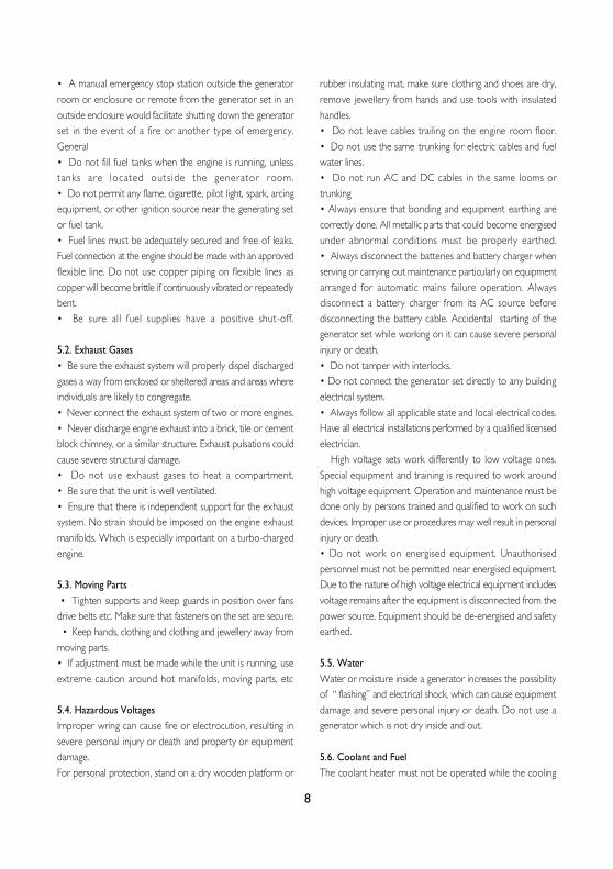
• A manual emergency stop station outside the generatorroom or enclosure or remote from the generator set in anoutside enclosure would facilitate shutting down the generatorset in the event of a fire or another type of emergency.General• Do not fill fuel tanks when the engine is running, unlesstanks are located outside the generator room.• Do not permit any flame, cigarette, pilot light, spark, arcingequipment, or other ignition source near the generating setor fuel tank.• Fuel lines must be adequately secured and free of leaks.Fuel connection at the engine should be made with an approvedflexible line. Do not use copper piping on flexible lines ascopper will become brittle if continuously vibrated or repeatedlybent.• Be sure all fuel supplies have a positive shut-off.
5.2. Exhaust Gases• Be sure the exhaust system will properly dispel dischargedgases a way from enclosed or sheltered areas and areas whereindividuals are likely to congregate.• Never connect the exhaust system of two or more engines.• Never discharge engine exhaust into a brick, tile or cementblock chimney, or a similar structure. Exhaust pulsations couldcause severe structural damage.• Do not use exhaust gases to heat a compartment.• Be sure that the unit is well ventilated.• Ensure that there is independent support for the exhaustsystem. No strain should be imposed on the engine exhaustmanifolds. Which is especially important on a turbo-chargedengine.
5.3. Moving Parts • Tighten supports and keep guards in position over fansdrive belts etc. Make sure that fasteners on the set are secure. • Keep hands, clothing and clothing and jewellery away frommoving parts.• If adjustment must be made while the unit is running, useextreme caution around hot manifolds, moving parts, etc
5.4. Hazardous VoltagesImproper wring can cause fire or electrocution, resulting insevere personal injury or death and property or equipmentdamage.For personal protection, stand on a dry wooden platform or
rubber insulating mat, make sure clothing and shoes are dry,remove jewellery from hands and use tools with insulatedhandles.• Do not leave cables trailing on the engine room floor.• Do not use the same trunking for electric cables and fuelwater lines.• Do not run AC and DC cables in the same looms ortrunking• Always ensure that bonding and equipment earthing arecorrectly done. All metallic parts that could become energisedunder abnormal conditions must be properly earthed.• Always disconnect the batteries and battery charger whenserving or carrying out maintenance particularly on equipmentarranged for automatic mains failure operation. Alwaysdisconnect a battery charger from its AC source beforedisconnecting the battery cable. Accidental starting of thegenerator set while working on it can cause severe personalinjury or death.• Do not tamper with interlocks.• Do not connect the generator set directly to any buildingelectrical system.• Always follow all applicable state and local electrical codes.Have all electrical installations performed by a qualified licensedelectrician. High voltage sets work differently to low voltage ones.Special equipment and training is required to work aroundhigh voltage equipment. Operation and maintenance must bedone only by persons trained and qualified to work on suchdevices. Improper use or procedures may well result in personalinjury or death.• Do not work on energised equipment. Unauthorisedpersonnel must not be permitted near energised equipment.Due to the nature of high voltage electrical equipment includesvoltage remains after the equipment is disconnected from thepower source. Equipment should be de-energised and safetyearthed.
5.5. WaterWater or moisture inside a generator increases the possibilityof “ flashing” and electrical shock, which can cause equipmentdamage and severe personal injury or death. Do not use agenerator which is not dry inside and out.
5.6. Coolant and FuelThe coolant heater must not be operated while the cooling
8

system is empty or when the engine is running or damage tothe heater will occur. Coolant under pressure have a higherboiling point than water.• Do not open a radiator, heat exchanger or header tankpressure cap while the engine is running. Allow the generatorset to cool and bleed the system pressure f irst.• Never use galvanised or copper fuel lines, fittings or fueltanks. Condensation in the thanks and lines combines with thesulphur in the fuel to produce sulphuric acid. The molecularstructure of the copper or galvanised lines or thanks reactswith the acid and contaminates the fuel.
6. GENERAL PRECAUTIONS AND CONTROLS WHICHMUST BE DONE BEFORE STARTING UP THEGENERATING SET.• Make a general visual inspection on the engine and alternator.Check if there is any breakage, crack, indentation, leakage orlooseness. Never operate the generating set before removingany fault, if any.• Take out foreign materials such as keys, tools, cleaning wool,papers etc. on the engine and the alternator.• Check the fuel level in day tank. Refill with fuel if it is low.• Check the lubrication oil level on the dipstick. Refill with anappropriate oil if it is low. Oil level normally must be close tothe maximum level line.• Look at the water level by opening the radiator tap. If it isinadequate add more water.• Engine cooling water must include antifreeze according tothe coolest weather conditions in the area. A mixture of 50%antifreeze and 50% water provides a good protection in allarea.• Check the air filter gauge. Clean or replace air filter, ifnecessary.• Keep the inlet opening open.• Make sure that the generating set can easily take air fromthe environment.• Check the battery connection cables. Take care to tightenthe loosened battery terminals with spanner and, cover withspecial substance and keep clean in order to avoid oxidation.• Open the battery caps and check the liquid level in the cellsfor maintenance type battery. Add distilled water, if necessary,so as to be 1 cm higher than the separation. Never fill thecells with tap water, acid water or acid.• Check if the circuit breaker outlet switch is in OFF position.• Make sure that the emergency stop button is not pressed
Figure 6.1. External Engine Components
7. GENERAT ING SET CONTROL SYSTEMSTo control and monitor the generating set, an electroniccontrol system has been used.P 72 model control system is fitted. Control panel providesa means of starting and stopping the generating set, monitoringits operation and output and automatically shutting down theset in the event of critical condition arising such as low oilpressure or high engine temperature.
7.1. Control PanelControl, supervision and protection panels are mounted onthe generator base frame.
7.1.1. Control System P 72 Panel SpecificationsThe control panel is equipped as follows:Equipments:- Control with DSE, model 720 module- Static battery charger- Emergency stop push button.
DSE 720 Module Features- To monitoring AC mains supply- Automatic controls generating set, start and stop- Provide signal to change over switch- Scrolling digital LCD display- Front panel configuration of timers and alarm trip points- Easy push button controlSTOP/RESET - MANUAL – AUTO – TEST – STARTMetering via LCD display- Generator Volt (L – N)- Generator Ampere (L1, L2, L3)- Generator Frequency (Hz)- Mains Volt (L – L / L – N)- Engine cooling temperature
9

10
- Engine oil pressure- Engine speed- Engine hours run- Engine battery volt
Alarms• Over current • High engine temperature• Over speed • Low battery volt• Under / Over mains volt • Charge fail• Under / Over mains frequency • Start failure• Low oil pressure • Emergency stop
LED indication• Mains available • Generator available• Mains on load • Generator on load
7.1.2. Static Battery Trickle ChargerThis charger is designed to ensure that the starter batteriesmaintain their charge even if the generating set is not operatedfor long periods.As an option, a battery charger ammeter may be fitted to thecontrol panel in order for the operator to monitor thefunctioning of the battery charger.
7.2. Control System OptionsA large variety of options may be fitted to customize thecontrol system to a specific installation.
7.2.1. HeatersAlternator anti-condensation heaters may be fitted to thealternator stator winding to keep them dry in humid conditions.Panel anti-condensation heaters may be fitted in the controlpanel to keep moisture levels down.
8. GENERAL PRECAUTIONS AND CONTROLS WHICHMUST BE DONE AFTER STARTING UP THEGENERATING SET• Check for any abnormal noise or vibration on the generatingset.• Check if the exhaust system has any leakage.• Monitor the generating set operation by means of thecontrol module LCD display. Check the engine temperatureand oil pressure. Oil pressure must reach the normal value 10seconds after the generating set operation.• Monitor the generating set outlet voltage and frequency
by means of the control module LCD display. Check thevoltage, if the voltage between phases is 400 V. and betweenphase and neutral is 230 V. check that the frequency is 51 -52 Hz on generating sets with mechanical governors and 50Hz on generating sets with electronic governors.• If an engine block water heater is not available, run thegenerating set at no-load for 8 minutes and when the enginewarm than apply on load (for manual models) Apply load tothe generating set as follows:• Set the alternator outlet circuit breaker on the panel toON position.• Set the load circuit beakers (or fuses) on the distributionpanel to ON position one by one. This way, the generatingset cannot be suddenly put under full load. Otherwise, theengine stalling or alternator winding insulation of formation orburning can occur.• Set the alternator outlet circuit breaker on the circuit toOFF position before stop the generating set.• Continue to run the unloaded engine for purpose of coolingperiod for 5 minutes and then stop.• Never operate the generating set before removing any fault,if any.
9. LUBR‹CAT‹NG O‹LOil system of diesel engine is one of the most importantelements of the engine. Correctly made engine overhaul (thissubject includes oil change periods, filter change periods, payingattention about selecting the true type of oil) prolongs the lifecost of the engine.
9.1. Oil Performance Properties The American Petroleum Institute (API) the American Societyfor Testing and Materials (ASTM) and Society of AutomotiveEngineers (SAE) has developed and preserved a system inorder to classify the lubrication oils for their performancecategories
9.2. Lubrication Oil Recommendations for Lister PetterEnginesTo help assist engine running-in, all engines are dispatchedwith an initial fill lubricating oil which must be changed after100 hours.1. The temperatures mentioned in the tables are the ambienttemperatures at the time when the engine is started. However,if monograde oils are used and running ambient temperatures
are significantly higher than starting temperatures, a higherviscosity oil should be selected subject to satisfactory startingperformance. Multigrade oils may be used to overcome theproblem.2. Where it is not practical to continually change oils to suitvarying ambient temperatures a suitable multigrade oil isrecommended to ensure adequate starting performance atthe lowest temperature likely to be encountered.3. All engines must be run on heavy duty lubricating oils thatat least meet the requirements of the fol lowing:
API CCDEF2101D
Straight mineral oils are not suitable, neither are oils of lessdetergency than specified.Note: Higher specification oils meeting API CD, API CE andAPI CF-4 are more commonly available than API CC. The useof these oils in new engines is acceptable for topping up the‘first fill’ and following the first 100 hours when running-in hasbeen completed.These oils are particularly suited to engines running at a highload factor, or in conjunction with high ambient temperatures.They must also be used where the sulphur content of the fuelexceeds 0,5%.
CAUTION !API CD, API CE or API CF-4 oils can inhibit the running-inprocess in new or reconditioned engines and are not suitablefor engines running on low duty cycles.
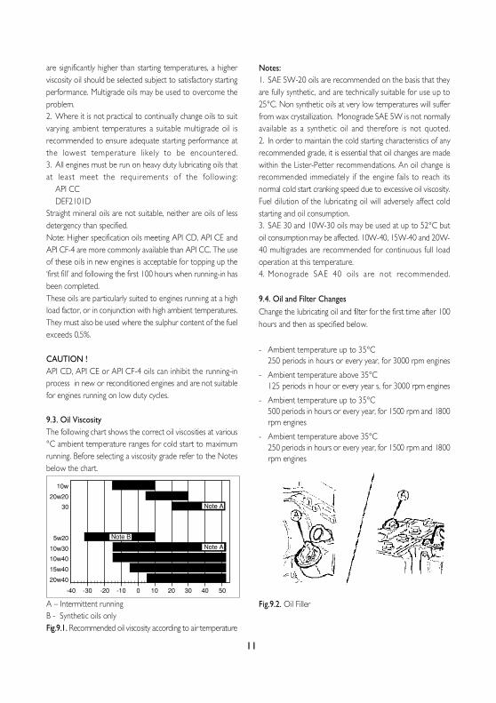
9.3. Oil ViscosityThe following chart shows the correct oil viscosities at various°C ambient temperature ranges for cold start to maximumrunning. Before selecting a viscosity grade refer to the Notesbelow the chart.
A – Intermittent runningB - Synthetic oils onlyFig.9.1. Recommended oil viscosity according to air temperature
Notes:1. SAE 5W-20 oils are recommended on the basis that theyare fully synthetic, and are technically suitable for use up to25°C. Non synthetic oils at very low temperatures will sufferfrom wax crystallization. Monograde SAE 5W is not normallyavailable as a synthetic oil and therefore is not quoted.2. In order to maintain the cold starting characteristics of anyrecommended grade, it is essential that oil changes are madewithin the Lister-Petter recommendations. An oil change isrecommended immediately if the engine fails to reach itsnormal cold start cranking speed due to excessive oil viscosity.Fuel dilution of the lubricating oil will adversely affect coldstarting and oil consumption.3. SAE 30 and 10W-30 oils may be used at up to 52°C butoil consumption may be affected. 10W-40, 15W-40 and 20W-40 multigrades are recommended for continuous full loadoperation at this temperature.4. Monograde SAE 40 oils are not recommended.
9.4. Oil and Filter ChangesChange the lubricating oil and filter for the first time after 100hours and then as specified below.
- Ambient temperature up to 35°C250 periods in hours or every year, for 3000 rpm engines
- Ambient temperature above 35°C125 periods in hour or every year s, for 3000 rpm engines
- Ambient temperature up to 35°C500 periods in hours or every year, for 1500 rpm and 1800rpm engines
- Ambient temperature above 35°C250 periods in hours or every year, for 1500 rpm and 1800rpm engines
Fig.9.2. Oil Filler
11
10w
20w20
30
5w20
10w30
10w40
15w40
20w40
-40 -30 -20 -10 0 10 20 30 40 50
Note B
Note A
Note A
10. GENERAT‹NG SET MAINTENANCEA good maintenance program is the key to long generatingset life. Maintenance and service should only be carried outby qualified technicians. The maintenance and service whichare done must be recorded to the Maintenance Record Form.In general, the generating set should be kept clean. Do notpermit liquids such as fuel or oil film to accumulate on anyinternal or external surfaces. Wipe down surfaces using anaqueous industrial cleaner.
10.1. Maintenance Schedule for Generator SetsUsing hour meter as a guide, perform all services at the hourlyintervals indicated on following. At each maintenance interval,perform all previous maintenance operations in addition tothe ones specified. Keep a record of hourly intervals andservices performed.
Important: Recommended service intervals are for normaloperating conditions. Service MORE OFTEN if engine isoperated under adverse conditions. Neglecting maintenancecan result in failures or permanent damage to the engine.Use correct fuels, Lubricants and coolant.
A. Daily or every 20 hoursCheck• Visually inspect engine, generator, transfer switch and controlpanel.• For, Oil, Water and Fuel leaks.• For, Coolant level, Oil level, Fuel level• Battery charge level
• Operation of coolant heater• Drain Fuel/Water separator• Inspect the engine fan blades• Inspect the drive belt
B. WeeklyRepeat DailyCheck
Fuel System• Fuel level in main tank• Day tank float switch• Fuel transfer pump operation• Fuel lines and connections
Cooling System• Adequate fresh air to engine• Hose and connections• Battery charging alternator belts• Inspect the engine fan blades• Inspect the fan belt
Lubricating System• Oil level• Tighten connections
Exhaust System• Exhaust leaks• Tighten connections
12
API CCDEF 2101D
ALP 8
ALP 12
ALP 15
ALP 18
ALP 22
ALP 30
8
12
15
17,5
22
30
LPW 2
LPW 3
LPW 2
LPW 4
LPW 3
LPW 4
1,9
2,8
3,9
3,8
5,9
7,8
50
50
50
70
50
70
5,5
6,5
5,5
7,5
6,5
7,5
3,2
4
3,2
5,8
4
5,8
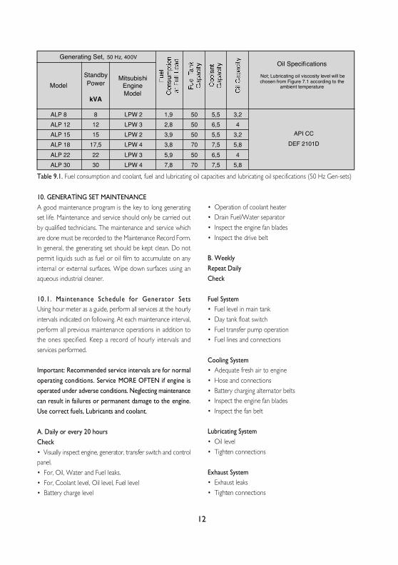
Table 9.1. Fuel consumption and coolant, fuel and lubricating oil capacities and lubricating oil specifications (50 Hz Gen-sets)
Generating Set, 50 Hz, 400VOil Specifications
Not; Lubricating oil viscosity level will bechosen from Figure 7.1 according to the
ambient temperatureModelStandbyPower
kVA
MitsubishiEngineModel

13
Generator• Vent screens• Tighten covers• Output voltage and frequency
Transfer Switch• Operation under load• No unusual sounds• Terminals and connections normal colour• Doors closed securely
C. First 100 service hours for new or overhauled engine• Changing engine oil and oil filter• Re-tighten bolds and nuts on engine
D. Every 250 service hours or every 1 year• Changing engine oil and oil filter• Checking and cleaning radiator fins for contamination orblockage• Check the condition and tension of the radiator drive belt.• Clean the fuel injector nozzles if the exhaust is dirty• Renew the fuel filter element if the fuel is not perfectlyclean.
E. Every 500 service hours• Checking V-belt and adjusting belt tension• Renew the fuel filter element.• Renew the air cleaner element.• Check the air induction system for leaks, damage andrestrictions.
F. Every 1000 service hours• Check all external nuts, bolts and unions for tightness.• Ensure that all guards are firmly attached and not damaged• Replace the fuel lift pump diaphragm; see Note:
G. Every 2000 service hours• Decarbonise, if performance has deteriorated, renewing alljoints and seals as necessary.• Check the engine and speed controls for free movement.• Clean and check, or replace, the fuel injector nozzles.• Check the radiator fins and radiator fan blades for damage.• Replace the fan drive belt• Check the lubricating oil pressure.• Renew the air cleaner element.
H. Every 6000 service hours• The previous items and give the engine a major overhaul,if necessary
I. Every 1 years• Drain and flush block water heater tube.• Drain, flush and refill the cooling system adding new coolantconcentrate to a 40% concentration.• Drain and replace the lubricating oil and filter, irrespectiveof their condition, if the engine has run for less than 250 hoursin the preceding twelve months.
J. Every 2 years• Replace the coolant hoses irrespective of their condition.
K. As required• Cleaning, checking, replacing air cleaner element• Bleeding fuel system• Draining water sedimenter
Note:It is recommended that the fuel lift pump diaphragm is inspectedat more frequent intervals if it is known the fuel is contaminated.It should also be inspected at regular intervals on engines inlow duty cycle applications; for example, stand-by generatingsets.
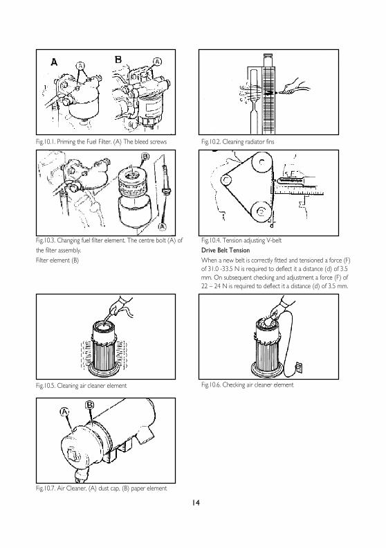
Fig.10.1. Priming the Fuel Filter. (A) The bleed screws
Fig.10.3. Changing fuel filter element. The centre bolt (A) ofthe filter assembly.Filter element (B)
Fig.10.5. Cleaning air cleaner element
Fig.10.7. Air Cleaner, (A) dust cap, (B) paper element
Fig.10.2. Cleaning radiator fins
Fig.10.4. Tension adjusting V-beltDrive Belt TensionWhen a new belt is correctly fitted and tensioned a force (F)of 31.0 -33.5 N is required to deflect it a distance (d) of 3.5mm. On subsequent checking and adjustment a force (F) of22 – 24 N is required to deflect it a distance (d) of 3.5 mm.
Fig.10.6. Checking air cleaner element
14
15
11. ENGINE TROUBLESHOOTINGThe starter motor turns the engine too slowly:• Battery capacity to low• Bad electrical connection• Faulty in starter motor• Wrong grade of lubricating oil
The engine does not start or difficult to start:• Starter motor turns engine too slowly• Fuel tank empty• Fault in fuel control solenoid• Restriction in a fuel pipe• Fault in fuel lift pump• Dirty fuel filter element• Air in fuel system• Fault in atomisers• Colt start systems used incorrectly• Fault in cold start system• Restriction in fuel tank vent• Wrong type or grade of fuel used• Restriction in exhaust pipe
Not enough power:• Restriction in a fuel pipe• Fault in fuel lift pump• Dirty fuel filter element• Air in fuel system• Restriction air filter/cleaner or induction system• Restriction in exhaust pipe• Fault in atomisers or atomisers of an incorrect type• Restriction in fuel tank vent• Wrong type or grade of fuel used• Restricted movement of engine speed control• Engine temperature is too high or low• Loss of compression
Misfire• Restriction in a fuel pipe• Fault in fuel lift pump• Dirty fuel filter element• Air in fuel system• Fault in atomisers or atomisers of an incorrect type• Fault in cold start system• Engine temperature is too high• Incorrect valve tip clearances
The pressure of the lubrication oil is too low:• Wrong grade of lubrication• Not enough lubrication oil in sump• Defective gauge• Dirty lubrication oil filter element
High fuel consumption:• Restriction air filter/cleaner or induction system• Fault in atomisers or atomisers of an incorrect type• Fault in cold start system• Wrong type or grade of fuel used• Restricted movement of engine speed control• Restriction in exhaust pipe• Engine temperature is too low• Incorrect valve tip clearances
Black exhaust smoke:• Restriction air filter/cleaner or induction system• Fault in atomisers or atomisers of an incorrect type• Fault in cold start system• Wrong type or grade of fuel used• Restriction in exhaust pipe• Engine temperature is too low• In correct valve tip clearances• Engine over load
Blue or white exhaust smoke• Wrong grade of lubrication• Fault in cold start system• Heavy blue smoke – caused by lubricating oilPassing the piston due to:Stuck, worn or broken rings. Worn cylinder bore Overfull oilsump• Engine temperature is too low• White smoke- generally as a result of water entering thecylinder.
The engine knocks:• Fault in fuel lift pump• Fault in atomisers or atomisers of an incorrect type• Wrong type or grade of fuel used• Fault in cold start system• Engine temperature is too high• In correct valve tip clearances

16
12. ALTERNATOR DESCRIPTION12.1. GeneralThe alternator fitted on the generating set is of the brushlessself-excitation type which eliminates the maintenance associatedwith slip rings and brushes. The control system, consist of anautomatic voltage regula tor , protect ive ci rcui ts.
12.2. Construction and ComponentsThe stator core is produced from insulated low loss electricalgrade sheet steel laminations. These are built and weldedunder a fixed pressure to give an extremely rigid core towithstand vibration and load impulses. The complete woundstator is, after impregnation, pressed into the frame and pinnedinto position.The rotor assembly, which comprises the alternator rotatingfield systems, the exciter rotating diode system and the coolingfan. The complete rotor assembly is dynamically balanced toensure vibration-free running.At the drive end of the rotor assembly a cast-aluminumcentrifugal fan draws cooling air through screened covers atthe non drive end and discharges it through similar sidemounted covers at the drive end.
12.3. OperationThe electrical power produced by the generating set is derivedfrom a closed loop system consisting principally of the exciterrotor the man revolving field and the automatic voltage regulator(see Figure 12.1)The process begins when the engine starts to rotate theinternal components of the alternator. The residual magnetismin the main rotor produces a small alternating voltage (AC)in the main stator. The automatic voltage regulator rectifiesthis voltage (converts it to DC) and applies it to the exciterstator.This DC current to the exciter stator creates a magnetic fieldwhich in turn, induces an AC voltage in the exciter rotor. ThisAC voltage is converted back to DC by the rotating diodes.
When this DC voltage appears at the main rotor, a strongermagnetic field than the original residual field is created whichinduces a higher voltage in the main stator. This higher voltagecirculates through the system inducing an even higher DCvoltage back at the main rotor. This cycle continuous to buildup the voltage unit it approaches the proper output level ofthe generating set. At this point the automatic voltage regulator
begins to limit the voltage being passed to the exciter statorwhich, in turn, limits the overall power output of the alternator.This build-up process takes place in less than one second.
12.4. Automatic Voltage RegulatorThe Automatic Voltage Regulator (AVR) maintains a no loadto full load steady state voltage to tight tolerances. The AVRhas a volt/herz characteristic which proportionally reduces theregulated voltage at reduced speeds.
12.5. Insulation Test:Before starting the generating set after installation, test theinsulation resistance of the windings. The Automatic VoltageRegulator (AVR) should be disconnected and the rotatingdiodes either shorted out with temporary links or disconnected.Any control wir ing must a lso be disconnected.A 500 V Megger or similar instrument should be used.Disconnect any earthing conductor connected between neutraland earth and megger an output terminal to earth. The insulationresistance should be in excess of 1 MΩ to earth. Should theinsulation resistance be less than 1 MΩ the winding must bedried out.
Figure.12.1. Alternator, operating principles block schematicdiagram
‹zlemeA.V.R.
Voltaj ayar›
Ç›k›fl
Beslemeyrd. sarg›
‹kazstatoru
‹kazsotoru
Döner diyotAna rotor
Ana stator
Mekanikdöndürmeba¤lant›s›

17
13.Meccalte Alternator Troubleshooting
14. STORAGELong term can have detrimental effects on both the engineand alternator. These effects can be minimized by properlypreparing and storing the generating set.14.1. Storage- Store the generator in a dry, frost-free room which is wellventilated.- Run the engine regularly, eg. Once a week, until it is warmedup. If this is impossible, extra precautions must be taken:- Consult the engine’s operator manual.
- Remove the battery. Store it in a dry, frost-free room. Keepthe battery clean and its terminals lightly covered with petroleum jelly. Recharge the battery regularly.
- Clean the generator and protect all electrical componentsagainst moisture.- Stick sheets of VCI paper with adhesive tape on thebodywork to close off all openings.- Wrap the generator, except the bottom, with a plastic bag. If possible use space heaters to keep the windings dry.
Possible CauseSymptom Corrective Action
Alternator does not exciteBlown fuseInsufficient residual voltageNo residual voltage
Replace fuseIncrease speed by 15 %.For an instant apply on the (+) and (-)terminals of the electronic regulator a12V battery with 30 ohm resistor inseries respecting the polarities.
After being excited alternator doesno excite
Connections are interruptedCheck connection cables as perattached drawings.
Low voltage at no loadVoltage potentiometer out of settingInvention of protection.Winding failure
Reset voltageCheck engine speedCheck windings
High voltage at no loadVoltage potentiometer out of settingFailed regulator
Reset voltage potentiometerSubstitute regulator
Lower than rated voltage at load
Voltage potentiometer out of settingIntervention by protectionFailed regulatorRotating bridge failure
Reset voltage potentiometerCurrent to high, power factor lowerthan 0,8; speed lower than 4% of ratedspeedSubstitute regulatorCheck diodes, disconnect cables.
Higher than rated voltage at loadVoltage potentiometer out of settingFailed regulator
Reset voltage potentiometerSubstitute regulator
Unstable voltageSpeed variation in engineRegulator out of setting
Check regularity of rotationRegulate stability of regulator by actingon stability potentiometer.

18
14.2. Alternator Storage:When an alternator is in storage, moisture tends to condensein the windings. To minimize condensation, store the generatingset in a dry storage area. If possible use space heaters to keepthe windings dry.
14.3. Battery Storage:While the battery is stored, it should receive a refreshingcharge every 8 weeks up to a fully charged condition
14.4. Preparing for Operation After StorageBefore operating the generator again, remove the wrapping,VCI paper and check the generator thoroughly (go throughthe checklist “6. Before starting”).- Consult the engine’s operator manual.- Check that the insulation resistance of the generator exceeds5 M?.- Reinstall and connect the battery, if necessary after beingrecharged.- Submit the generator to a test run.After removing the generating set from storage, perform aninsulation check as discussed in Section 12.5.
15. GENERAL PRECAUTIONS ABOUT WARRANTYDEAR AKSA GENERATING SET OPERATOR,PLEASE TAKE CARE TO THE FOLLOW›NG ORDER TOPREVENT THE GENERAT›NG SET WARRANTY TOBECOME ›NVAL›D BEFORE THE TERM›NAT›ON OF THEWARRANTY PER›OD AND TO ENSURE TROUBLE-FREEOPERAT›ON OF THE GENERAT›NG SET W›TH A LONGL›FE!
• MA›NTENANCE AND REPA›R WORKS W›LL NOTBE COVERED BY THE WARRANTY CERT›F›CATE, ›NVO›CE OR DEL›VERY CERT›F›CATE OF THEGENERAT›NG SET ›S SUBM›TTED.• THE WARRANTY OF THE GENERATING SET WILLBECOME INVALIDE IN CASE OF ANY INTERVENTIONOF ANY PERSON OTHER THAN AUTHORIZED AKSASERVICES OR BY PRIOR WRITTEN APPROVAL FROMAKSA POWER GENERATION ON THE GENERATINGSET FOR ANY REASON.• CONTROL AND MAINTENANCE WORKSINDICATED IN THE PERIODICAL MAINTENANCESCHEDULE AND THE OPERATING MANUAL MUST BE
CARRIED OUT COMPLETELY AND TIMELY THE FAILURES DUE TO INCOMPLATE OR UNTIMELY MAINTENANCEARE NOT COVERED BY THE WARRANTY .• GENERATING SET SHOULD BE MOUNTED ASINDICATED IN THE OPERATING MANUAL OTHERWISE,THE PROBLEMS WHICH ARE LIKELY TO OCCUR WILLNOT BE COVERED BY THE WARRANTY CUSTOMER ISRESPONSIBLE FOR THE FAILURES WHICH ARE LIKELYTO OCCUR IN CASE THAT THE DIESEL OIL USEDCONTAINS DIRT OR WATER.• THE OIL TYPE INDICATED IN THE OPERATINGMANUAL SHOULD BE USED IN THE ENGINEOTHERWISE, THE FAILURES WHICH ARE LIKELY TOOCCUR WILL NOT BE COVERED BY THE WARRANTY.• BATTERIES WILL NOT BE COVERED BY THEWARRANTY IF THEY ARE SUBJECTED TO BREAKAGE,EXCESSIVE ACID FILL OR HARDNING BY LEAVINGUNCHARGED.• GENERATING SETS, NEVER START OR STOP THEDIESEL ENGINE WHEN THE GENERATING SET IS UNDERLOAD. ENGINE SHOULD BE STARTED AND STOPPEDAFTER LOAD IS DISCONNECTED AND THEGENERATING SET IS AT IDLE CONDITION. OTHERWISE,THE VALVES CAN BE SEIZED, THE VOLTAGEREGULATOR, TRANSFORMER AND DIODES CAN BEBROKEN DOWN. THESE CONDITIONS ARE NOTCOVERED WARRANTY.• OUR COMPANY DOES NOT TAKE THERESPONSIBILITY OF THE DAMAGES ON THE MAINSSUPPLY CONTACTOR OF THE AUTOMATICGENERATING SETS DUE TO OVERCURRENT, LOW ORHIGH VOLTAGE.• NEVER REMOVE THE BATTERY TERMINALS WHILETHE GENERATING SET IS IN USE. EVEN A MOMENT OFDISCONNECTION CAN CAUSE A DAMAGE ON THEELECTRONIC CLOSING RELAY OF THE CHARGEALTERNATOR AND ON THE ELECTRONIC ENGINESPEED CONTROL CIRCUIT THESE CONDITIONS ARENOT COVERED BY THE WARRANTY.• FAILURES DUE TO OVERLOAD AND UNBALANCEDLOAD IN EXCESS OF THE GENERATING SET POWER(SUCH AS ALTERNATOR AND CONTACTOR FAILURES)ARE NOT COVERED BY THE WARRANTY .
• WHEN THE MANUAL GENERATING SET IS STARTEDUP, IT SHOULD BE WARMED BY OPERATING AT IDLEFOR 5 MINUTES . WHEN STOPPING THE DIESEL ENGINE,IT SHOULD BE UNLOADED AND THEN CONTINUEDTO BE OPERATED FOR COLOLING FOR 10 MINUTESBEFORE STOPPING. OTHERWISE PROBLEMS WHICHARE LIKELY TO OCCUR WILL NOT BE COVERED BYTHE WARRANTY• WARRANTY PERIOD IS 1 YEAR BEGINNING FROMTHE PURCHASE DATE.
Authorized Service Dealer may perform warranty repairs.Most warranty repairs are handled routinely, but sometimesrequests for warranty service may not be appropriate. Forexample, warranty service would not apply if equipmentdamage occurred because of misuse, lack of routinemaintenance, shipping, handling, warehousing or improperinstallation. Similarly, the warranty is void if the manufacturingdate or the serial number on the equipment has been removedor the equipment has been altered or modified. During thewarranty period, the Authorized Service Dealer, at its option,will repair or replace any part that, upon examination, is foundto be defective under normal use and service. This warrantywill not cover the following repairs and equipment:• Normal Wear: Power Equipment and engines, like allmechanical devices, needs periodic parts and service to performwell. This warranty does not cover repair when normal usehas exhausted the life of a part or the equipment.• Installation and Maintenance: This warranty does not applyto equipment or parts that have been subjected to improperor unauthorized installation or alteration and modification,misuse, negligence, accident, overloading, over speeding,improper maintenance, repair or storage so as, in our judgment,to adversely affect its performance and reliability. This warrantyalso does not cover normal maintenance such as adjustments,fuel system cleaning and obstruction (due to chemical, dirt,carbon, lime, and so forth).• Other Exclusions: This warranty excludes wear items suchas oil gauges, o-rings, filters, fuses, or spark plugs, etc., ordamage or malfunctions resulting from accidents, abuse,modifications, alterations, or improper servicing or freezingor chemical deterioration. Accessory parts are excluded fromthe product warranty. This warranty excludes failures due toacts of God and other force majeure events beyond themanufacturers control.
19

‹STANBUL AVRUPA YAKASI
‹STANBUL ANADOLU YAKASI
‹STANBUL DIfiI SERV‹S NOKTALARI
ANKARAÇET‹N EMEÇ BULVARI 2.CAD. 1309 SK. NO:7/A ÖVEÇLER
T:0312 472 71 71 F:0312 472 76 01
ADANATURHAN CEMAL BER‹KER BUL. MERKEZ CAD.
ADANA ‹fi MERKEZ‹ A BLOK NO:24/27 YEfi‹LOBA SEYHANT:0322 428 11 61 PBX F: 0322 428 15 40
ANTALYAYEfi‹LOVA MAH. ASPENDOS BULVARI 196-1T:0242 322 16 88 – 322 91 88 F:0242 322 97 55
BODRUMATATÜRK BUL. BEYL‹KKIRLARI MEVK‹‹
BALKANO⁄LU-2 ‹fi MERKEZ‹ G-BLOK NO:1 KONACIKT:0252 358 70 30 F: 0252 358 70 25
BURSAN‹LÜFER T‹C. MRK. ALAADD‹NBEY MAH. 70 SK.
NO:30/A N‹LÜFERT:0224 443 53 15-16-17-18 F:0224 443 53 15
DEN‹ZL‹‹ZM‹R ASFALTI NO:56 GÜMÜfiLER
T:0258 371 71 10/372 08 44 F:0258 372 09 46
GAZ‹ANTEPFAT‹H MAH. FEVZ‹ ÇAKMAK BULVARI NO:152 fiEH‹TKÂM‹L
T:0342 321 39 59 F:0342 321 37 67
‹ZM‹RKAZIM D‹R‹K MAH. YEN‹YOL ANKARA CAD.
NO:75 BORNOVAT:0232 461 82 82 F:0232 462 24 63
KAYSER‹OSMAN KAVUNCU CAD. SOYLUM APT. NO:185/AMEL‹KGAZ‹ T:0352 336 17 42-43 F: 0352 336 17 40
D‹YARBAKIRURFA YOLU 1. KM. DR. SITKI GÖRAL CAD.
VELAT 3 APT.ALTI NO:1T:0412 238 04 44 PBX F:0412 238 10 11
MARMAR‹S DATÇA YOLU CAD. NO:14/B
T:0252 413 58 93 F: 0252 413 85 93
TRABZONYAVUZ SEL‹M BULVARI MANOLYA S‹TES‹ NO:281
T:0462 230 10 60-61 F: 0462 230 10 64
AVCILARMUSTAFA KEMAL PAfiA MAH. YILDIRIM BEYAZIT CAD. DEMET SOK. NO:132 AVCILAR/‹STANBUL
T:0 212 428 66 66 PBX F:0 212 423 22 22
BA⁄CILARORTAK BÖLGE (GÖKSU) FAT‹H, ZEYT‹NBURNU, GAZ‹OSMANPAfiA, EYÜP
MERKEZ MAH. ATATÜRK CAD. NO:24 YEN‹BOSNA T:0212 630 79 80/0212 630 79 98
KA⁄ITHANEÇA⁄LAYAN MAH. KA⁄ITHANE CAD. NO:93 KA⁄ITHANE
T:0212 222 13 38 PBX F:0212 210 08 81
KARAKÖYNECAT‹BEY CAD NO.74 KARAKÖY / ‹STANBUL T: 0212 251 92 48 - 293 07 32 - 33 F: 0212 251 92 64
DOLAPDERE SAN. S‹T. 13.ADA NO:9 ‹K‹TELL‹ T: 0212 671 35 48 - 49 F: 0212 671 35 41
SEFAKÖYYEfi‹LOVA MAH. D‹LEK SOK. NO:2 KÜÇÜKÇEKMECE
T:0212 425 65 80 (3 HAT) F:0212 425 65 84
KADIKÖYESK‹ ÜSKÜDAR YOLU CAD. MEZARLIK SK. NO:4 ‹ÇERENKÖY
T:0216 469 58 58
PEND‹KAYDINEVLER ÂfiIK VEYSEL SOK. AK PLAZA NO:24 KÜÇÜKYALI/MALTEPE
T:0216 489 68 68 PBX F:0216 489 21 60
IRAQAksa Power Generation (Iraq)English Village HouseNo:353 Arbil / IraqT : + 964 (0) 771 199 18 56e-mail: [email protected]
RUSSIAOOO AKCA107031, Petravka, 27Moscow - Russia 7108862T : + 7 495 710 88 62F : + 7 495 641 52 00e-mail : [email protected]
ALGERIAAksa AlgeriaChemin du Parc d'AttractionCooperative El Baraka No: 417 TixerainBir Moruad Rais / AlgerT : + 213 21 40 26 72F : + 213 21 40 27 94e-mail: [email protected]
CHINAAksa Power Generation(Changzhou) Co. Ltd.Export Processing ZoneXinzhu Road, Plant A1 - A2,Changzhou / ChinaT : + 86 (0) 519 851 50 205F : + 86 (0) 519 851 50 130e-mail: [email protected]
KAZAKHSTANAksa Kazakhstan Ltd.M54-6 Abdullinyh Str.Corner of Tole Bi Str.Almaty - KazakhstanT : + 7 727 250 67 31 / 250 67 41F : + 7 727 250 67 91e-mail: [email protected]
SINGAPOREAksa Far East(Pte.) Ltd.94 Tuas Avenue 11639103 SingaporeT : + 65 6863 2832F : + 65 6863 0392 - 6863 2956e-mail: [email protected]
U.A.E.Aksa Middle East FZEPost Box:18167 WarehouseNo.RA08 / LC07Jebel Ali Free Zone - DubaiT : + 971 4 880 91 40F : + 971 4 880 91 41e-mail: [email protected]
UNITED KINGDOMAksa International (UK) LtdUnit 6, Pine Court Walker Road,Bardon Hill Coalville Leicestershire,LE67 ISZ U.KingdomT : + 44 (0) 1530 837 472F : + 44 (0) 1530 519 577e-mail: [email protected]
VIETNAMAksa Vietnam43 Le Thi Hong Gam,Dist. 1, HCM City - VietnamT : + 84 8 391 47 014F : + 84 8 391 47 015e-mail: [email protected]


Related Documents


![lpwS engIneS - Lister Petter027-09108]1.pdf · lpwS engIneS lpwS2, lpwS3, ... spin-on lubricating oil filter • low oil pressure switch ... (subject to Lister Petter approval) Maximum](https://static.cupdf.com/doc/110x72/5aa231d37f8b9ada698c93fd/lpws-engines-lister-027-091081pdflpws-engines-lpws2-lpws3-spin-on-lubricating.jpg)