NASA Technical Memorandum 102113 AIAA 89-2739 Liquid Oxygen Cooling of Hydrocarbon Fueled Rocket Thrust Chambers Elizabeth S. Armstrong Lewis Research Center Cleveland, Ohio Prepared for the 25th Joint Propulsion Conference cosponsored by the AIAA, ASME, SAE, and ASEE Monterey, California, July 10-12, 1989 [NASA-TM-|02113) LIQUID OXYGEN COOLING OF HYDROCARBON FUELED ROCKET THRUST CHAMBERS _NASA. Lewis Research Center) 15 pCSCL 21H N89-24_47 Unclas G3/20 0217640 https://ntrs.nasa.gov/search.jsp?R=19890015076 2018-05-23T02:56:28+00:00Z

Welcome message from author
This document is posted to help you gain knowledge. Please leave a comment to let me know what you think about it! Share it to your friends and learn new things together.
Transcript
NASA Technical Memorandum 102113
AIAA 89-2739
Liquid Oxygen Cooling of HydrocarbonFueled Rocket Thrust Chambers
Elizabeth S. ArmstrongLewis Research Center
Cleveland, Ohio
Prepared for the
25th Joint Propulsion Conference
cosponsored by the AIAA, ASME, SAE, and ASEE
Monterey, California, July 10-12, 1989
[NASA-TM-|02113) LIQUID OXYGEN COOLING OFHYDROCARBON FUELED ROCKET THRUST CHAMBERS
_NASA. Lewis Research Center) 15 pCSCL 21H
N89-24_47
Unclas
G3/20 0217640
https://ntrs.nasa.gov/search.jsp?R=19890015076 2018-05-23T02:56:28+00:00Z


LIQUID OXYGEN COOLING OF HYDROCARBON
FUELED ROCKET THRUST CHAMBERS
Elizabeth S. Armstrong*
National Aeronautics and Space Administration
Lewis Research Center
Cleveland, Ohio 44135-3191
ABSTRACT
Rocket engines using liquid oxygen (LOX) and hydro-
carbon filel as tile propellant.s are being given serious
consideration for future launch vehicle propulsion. Nor-
really, the filel is used to regeneratively cool the com-
bustion chamber. However, hydrocarbons such as RP-1
are limited in their cooling capability. Another possi-
bility for the coolant is the liquid oxygen. Combustion
chambers previously tested with LOX and RP-1 as pro-
pellants and LOX as the coolant have denronstrated the
feasibility of using liquid oxygen as a coolant up to a
chamber pressure of 13.8 MPa (2000 psia). However,
there has been concern as to the effect on the integrity
of the chamber liner if oxygen leaks into the combustion
zone through fatigue cracks that may develop between
the cooling passages and the hot gas side wall.
In order to study this effect, chambers were fabri-
cated with slots machined upstream of the throat be-
tween the cooling passage wall and the hot gas side
wall to simulate cracks. The chambers were tested at a
nominal chamber pressure of 8.6 MPa (1247 psia) over
a range of mixture ratios front 1.9 to 3.1 using liquid
oxygen as the coolant. The results of the testing showed
that the leaking LOX did not have a deleterious effect
on the chambers in the region of the slots. However,
there was unexplained melting in the throat region of
both chambers, but not in line with the slots.
I. INTRODUCTION
Preliminary design studies 1'2 for future space trans-
portation systems have shown a need for high pressure
booster engines using liquid oxygen (LOX) and a hydro-
carbon fuel as the propellants. The candidate hydrocar-
bon filels for filture launch systems are RP-1, propane,
and methane.
Typically, the filel in a rocket engine is used to re-
generatively cool the combustion chamber. The disad-
*Aerospt_ce Engineer, member AIAA
vantage of RP-1, and even the lighter paraffinic hydro-
carbon propane, is decomposition (coking) in the cool-
ing passages and corrosion of the copper wall by trace
amounts of sulfitr-containing compounds. However, re-
cent testing 3 has shown that RP-1 and methane can be
used as coolants at coolant side wall temperatures up to
304 °C (580 °F) and 499 °C (930 °F), respectively, with-
out coking or corrosion if there are no sulfilr-containing
compounds present.
Because of the problems associated with hydrocar-
bon regenerative cooling, liquid oxygen is being consid-
ered as an alternative coolant. There are two concerns
with LOX as a coolant: 1) its effectiveness as a coolant,
and 2) its effect on the chamber liner if cracks develop.
Analyses 1'4 and experimental work 5-r have shown that
oxygen can cool rocket engines at chamber pressures up
to 27.6 MPa (4000 psia) and 8.6 MPa (1250 psia), re-
spectively, and still maintain reasonable pressure drops.
In the experimental work fatigue cracks developed in
the throat regions at chamber pressures of 4.1 MPa (600
psia) and 8.6 MPa (1250 psia) and the leaking LOX
coolant had no effect on the chamber wall. ttowever,
there was still some concern as to whether oxygen leak-
ing through cracks between the injector and the throat,
where the boundary layer has not been fnlly developed
and there is still combustion occurring, would affect the
integrity of the thrust chamber.
The objective of this program was to evaluate the ef-
fect of oxygen leaking into the coml>ustion zone through
cracks upstream of the thrust chamber throat, and
to acquire mort. experience using liquid oxvgt'n as a
coolant. Two thrust chambers had slots machined up-
slream of the throat between the cooling passage wall
and the hot gas side wall to simulate cracks. These
LOX-cooled thrust chambers were tested at a nominal
chamber pressure of 8.6 MPa (1247 psia) over a range
of mixture ratios from 1.9 to approximately 3.1. This
paper presents the results of those tests.
II. APPARATUS
Injector
Figure 1 shows a 61-element triplet injector with 4
radial rings of elements and a central quad element
that provided 3 oxidizer streams impinging on a straight
fuel stream. The three innermost radial rings were ar-
ranged in an oxidizer-fuel-oxidizer (O-F-O) sequeuce
to provide good propellant mixing, fuel vaporization,
and mass flux distribution. The outermost radial ring
consisted of F-O doublet showerheads to provide more
fuel in the outer zone, which resulted in film cooling of
tile cllamber wall. More details of the injector are given
in table I.
Resonator
A water-cooled resonator, as shown in figure 2, was
used in this investigation to provide stable combustion.
It was composed of 16 acoustic cavities arranged evenly
around its inside surface. The resonator was placed be-
tween the chamber and the injector. The cavities were
in line with the chamber at its edge and were 3.63 cm
(1.43 ill.) long. The injector formed the inner wall of
the cavities which was 2.54 em (1.0 ill.) long. This
corresponded to a quarter wave tube to dampen the
second tangential frequency of 9700 cycles/see which
was the expected frequency of the combustion oscil-
lations driving the instability. The hydrogen-oxygen
spark torch igniter was located in the resonator wall
just downstream of the acoustic cavities.
Combustion Chamber
Figure 3 shows the dimensions of the combustion
chambers nsed in this test program. The hot gas
liners were fabricated front oxygen-free, high conduc-
tivity (OFHC) copper and contained 100 axial milled
channels for the coolant passages. The passages were
closed out with electroformed nickel. The details of the
coolant channel dimensions are shown in figure 4.
Two combustion chambers were tested in this pro-
gram. Chamber 702 is shown in figure 5 during a fir-
ing. To determine the effects of cracks occurring up-
stream of the throat, both chambers were fabricated
with two machined slots 180 ° apart.. The machined
slots were not in the same eircunfferential location in
the two chambers relative to the injector, lnstead, the
slots in chamber 702 were 450 off from those in cham-
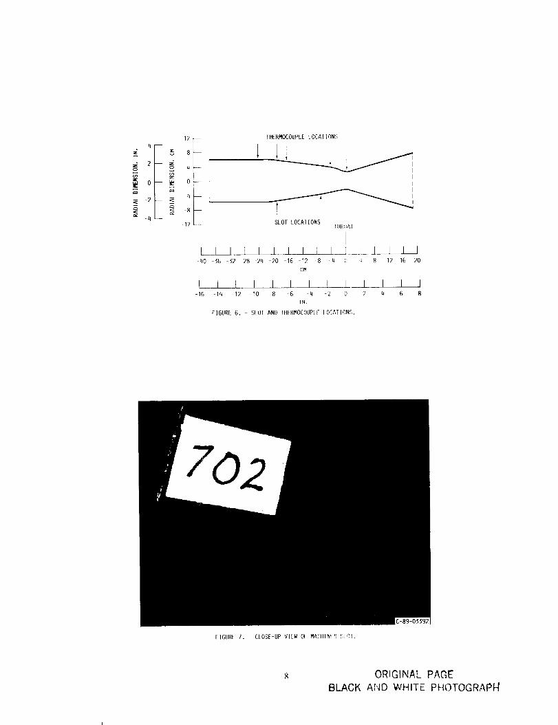
ber 703. The slots were 1.0 cm (.40 in.) long and .0127
cm (.05 in.) wide. On chamber 702, the machined
slots were located 7.0 cm (2.75 in.) upstream of the
throat, and on chamber 703 they were located 19.0 cm
(7.5 in.) upstream of the throat, as shown in figure 6.
Figure 7 shows a close-up view of one of the slots in
chamber 702. The thrust chambers were instrumented
with Chromel/Constantan thermocouples imbedded in
the rib between coolant channels approximately 1.30
mm (.051 in.) from the hot gas wall. Both chambers
had 20 thermocouph.s evenly spaced at 4 circumferen-
tim locations in 5 axial positions. As shown in figure 6,
the axial positions were 24.13 em (9.50 in.) upstream
of the thloat, 1(;.50 cm (6.50 in. ) upstream of the
throat, 4.44 cm (1.75 in.) upstream of the throat, at
the throat, and at the machined slots. The LOX in the
coolant passages used a separate feed system from the
LOX flowing through the injector. The LOX coolant
was countercurrcnt to the combustion gases and flowed
at approximately the same flowrate as the LOX used
as the oxidizer.
Test Facility
This program was conducted at the NASA Lewis Re-
search Center Rocket Engine Test Facility, a 222 400-N
(50 000 lbf) sea-level rocket test stand equipped with
a water-cooled exhaust-gas muffler and scrubber. The
scrubber cools the exhaust gases by spraying them with
1200 liters/sec (19 000 gal/min) of water. Details of the
facility are shown in figures 5. Figure 5 shows the thrust
stand above the oxhaust-gas scrubber with chalnber 702
monnted in plac_, f!ontrol room operations during test-
ing included monitoring of the test hardware by means
of two closed-circuit video cameras and one test-cell
microphone. 'File output of one video camera and the
microphone is recorded on video tapes for later play-
back. Two high speed photographic cameras record
each firing at a rate of 400 frames/sec. Also, a 35 mm
camera photographs the firings at 2 fraines/second for
still pictures.
During each test, data is recorded using a transient
data acquisition and recording systeln that records data
every .02 seconds and averages the data over 5 record-
ings, with the average reported every 0.1 seconds. The
data is then transferred to a centrally located main-
frame computer so that it can be easily accessed.
III. TEST PROCEDURE
The coml_usti,:,n chambers were tested at a nominal
chamber prcssur,, _)1"S._; MPa (1247 l)sia) and owq' a
mixture ratio ((_ F) range of 1.91 l(, 3. If1. Tabh' II giv,'s
the test conditi,ms f,,r tile test series. The hvdr,_en-
oxygen torch igniter, inserted into the combustion aroa
through a port in the resonator, was started prior to
the main propellant flow and supplies the energy nec-
essary to start the I,()X/flH, combustion. Before RP-
1 was brought into the injector, gaseous hydrogen was
introduced through the RP-1 line and LOX through a
separate line as the chamber pressure was brought up
to 1.70 MPa (246 psia) to insure smooth ignition. Af-
ter approxinlately 0.8 second, the chamber pressure was

ramped up to 8.6 MPa (1247 psia) in 0.3 second with
RP-1 and LOX propellants. With the RP-1 valve to
the tank open, this chamber pressure was maintainedfor 0.6 second. Then the RP-1 valve was closed and a
nitrogen purge was brought on. The purge maintainedthe chamber pressure for another 0.4 second as it emp-
tied the feed line of RP-1. Then the purge was dimin-
ished and the LOX propellant valve closed. The LOX
coolant valve was closed after the propellant valves to
cool the chamber after firing and to keep combustion
products from entering the coolant passages throughthe machined slots.
Test cycles were programmed into a solid-state timer
that is accurate and repeatable to within q-0.001 sec.
Fuel and oxidizer flows were controlled by fixed-position
valves and propellant tank pressure. Coolant inlet pres-sure was controlled by coolant tank pressure. Coolant
exit pressure was kept constant by a closed-loop con-
troller positioning a back pressure valve. After its use,
the coolant was vented to the atmosphere through a
ptechilled vent and the coolant vent line was purgedafter each test to insure that all the coolant had been
vented. The exhaust gases were directed into a water-
cooled scrubber where they were cooled by water sprays
flowing at 1200 liters/sec (19 000 gal/min), precipitat-ing unburned RP-1. The water sprays also muffled the
noise from combustion. After use in cooling the exhaust
gases, the water was retained in a detention tank and
then cycled through a waste treatment plant where all
nnburned RP-I was trapped and disposed of properly.
Between runs, the injector was purged to keep the in-jector clean of dirt. The processed data was available in
the control room from the mainframe computer withinminutes after a test. This access allowed for review of
the processed data prior to the next test.
IV. RESULTS AND DISCUSSION
Chamber 702 was fired twice. The chamber was in-
spected after one run and a melted region was detected
jnst upstream of the throat and at the throat. Severaloxygen-rich zones were also detected from discoloration
of the copper wall. The zones, which appear as streaks,
began at the injector face and continued past the throat
region. The melted region was in line circumferentially
with an oxygen-rich streak from the injector but not
in line with either machined slot. During the secondrun, the RP-I flow decreased, for reasons not yet de-termined. As a result, the mixture ratio increased from
about 2.39 at the beginning of the test to 3.72 at the
end, passing through the stoichiometric mixture ratio of
3.43. The chamber was inspected after the second run
and there was indication of more melting in the same
location, which opened up several coolant passages (fig-
ure 8). The reason for the severe melting is presently
undetermined. The injector was not damaged, but in
one area, the injector elements were discolored, indi-
cating a hot spot. Chamber 702 was then taken off the
test stand and sectioned. Figure 7 shows the slot clos-
est to the melted region. As can be seen, there is no
distinguishable effect from the leaking LOX in the re-
gion of the slot. Figures 9 and 10 show the damage tothe throat area and upstream of the throat in relation
to a machined slot and an oxygen-rich streak.
Six complete runs and one partial run were conducted
with chamber 703. After the first three runs, the cham-
ber was inspected and no evidence of damage was de-tected on the liner surface. The chamber was fired four
more times and then inspected again. A part of thechamber liner had melted at the throat and just up-
stream of the throat (figure 11). Several oxygen-rich
streaks were also detected from discoloration of the cop-
per wall. The streaks began at the injector face and
continued past the throat. The melted region was in
line circumferentially with an oxygen-rich streak from
the injector but not with either machined slot (figure
12). Again, the reason for the melting is presently un-determined. Chamber 703 was then taken off the test
stand and also sectioned. Again, there was no distin-
guishable effect on the chamber from the leaking LOXat the machined slots.
Figure 13 shows the melted region at the throat forthe two chambers. The line on the outside of each sec-
tion represents the same circumferential location rela-
tive to the injector face. As can be seen, the melted
regions were not in the same circumferential location.
Injector Performance
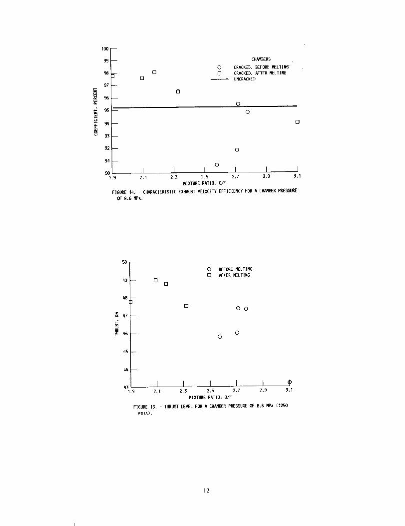
Figure 14 is a plot of the C" efficiency (characteris-
tic exhaust velocity efficiency) versus the mixture ratio
tested. As expected, the C._ efficiency increased after
melting occurred at the throat. The rise in efficiency
is a result of the additional mass flow coming into thechamber at the throat that was not accounted for in
the C" calculations. The C* efficiency for the slotted
chambers is generally higher than the C* efficiency us-ing identical hardware without machined slots _ for the
_ame reason. Figure 15 is a plot of the thrust level ver-
sus mixture ratio. This figure indicates that the thrust
level also increased after melting occurred a! the. throatdue to the increase in mass flow.
Effects of LOX Leaks on Chalnber Integrity
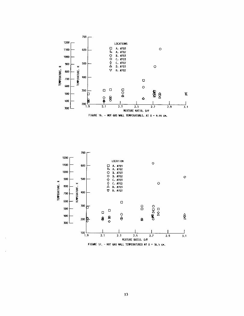
Thermoconples were located on the chambers at the
slot locations and 2.54 cm (1.0 in.) downstream of theslots to determine the effect of LOX leaks on wall tem-
perature. The temperatures 2.54 cm (1.0 in.) down-
stream of the slots in chamber 702 (4.44 cm upstream
of the throat) are compared for the two chambers in

figure 16, which shows similar temperatures for the twochambers. Location B on chamber 703 had very high
temperatures on runs 33 and 34 although no discernable
melting occurred during these runs. The tenrperatures2.54 cm downstream of the slots in chamber 703 (16.46
cm upstream of the throat) are conrpared for the twochambers in figure 18, which shows sinfilar tempera-tures for the two chambers. Location B oll chamber
702 had very high temperatures and was circumferen-
tially near tire melted throat region. This axial loca-
tion, however, is upstream of the slots, indicating that
these high temperatures at location B were not caused
by tire slots, but by the oxygen rich streak which began
at the injector face. Figures 16 and 17 do not. indicate
alry increase in temperature due to the slots in the area
just downstream of the slots. Also, there was no dele-terious effect on the chambers in the regic_n of the slots.
However, there were melted regions at the throat but
not in line with slots. The cause of the melted regions
has not yet been determined.
Possible Causes for Chamber Melting
A number of theories have been postulated as to the
cause of the melting in the throat region of the combus-tion chambers. The three most plausible theories are
discussed here as well as possible methods to determine
their validity.
Tire melting could be a result of an oxygen-rich zone,
which appears as a streak, beginning at. the injector face
and continuing past the throat. The melted regions onboth chambers were in line with streaks. However, in
previous testing e using the exact injector with similar
chanrbers under similar operating conditions, the cham-
bers had no melted regions after 26 cycles. To explore
this theory further, a new injector will be tested using
sinrilar chambers with slots upstream of the throat.
A second possible cause of melting is blocked coolant
passages. If several coolant passages are blocked, lo-
calized hot spots may result in those circumferen-tim locations. The chambers were sectioned and all
the channels were closely inspected for any blockage.
The coolant passages had been properly machined and
no blockage was found anywhere. Therefore, blocked
coolant passages are not the cause of the melting.
The third possible cause of melting is the effect from
machined slots upstream of the throat. The oxygen
flowing through the slots may have reacted with the
chamber wall at the throat, resulting in melting. How-
ever, from figure 7, one can see that the oxygen leakingfrom the slot did not react with the wall near the slot.
Also, the slots were not directly in line with the melted
region on either chamber. A similar chamber without
slots will be tested using the same injector that was
used in this program to determine if the slots were the
cause of the melting.
V. SUMMARY OF RESULTS
Two OFttC copper thrust chambers with identical
geometry were tested with LOX/RP-1 as propellantsand LOX as the coolant at a nominal chamber pres-
sure of 8.6 MPa (1247 psia) over a nfixture ratio (O/F)
range of 1.91 to 3.10. To determine the effect of leak-
ing LOX upstream of the throat, the thrust chamberswere fabricated with slots machined between the cool-
ing passage wall and the hot gas side wall, to simulatecracks. The results of these tests are as follows:
1. LOX leaks through slots in the cooling passagewall did not have a deleterious effect on the thrust
chambers in the regions of the slots.
2. There was unexplained melting in the throat region
of both chambers; however, the melting was not inline with the machined slots.
3. The cause of the melting has not yet been deter-mined.
VI. REFERENCES
1. Luscher, W.P.; and Mellish, J.A.: Advanced High
Pressure Engine Study for Mixed-Mode Vehicle
Applications. NASA C.R-135141, 1977.
2. Cahori, V.A.; Conrad, R.T.; and Jenkins, J.C.:
Technology Requirements for Future Earth-to-
Geosynchronous Orbit Transportation Systems.NASA CR-3265, 1980.
3. Rosenberg, S.D.; and Gage, M.L.: Compatibility ofHydrocarbon Fuels with Booster Engine Combus-
tion Chamber Liners. AIAA/ASEE/ASME/SAE24th Joint Propulsion Confereuce, AIAA paper 88-
3215, 1988.
4. Rousar, D.C.; and Miller, F.: Cooling with Super-
critical Oxygen. AIAA paper 75-1248, 1975.
5. Price, H.G.: Cooling of High-Pressure RocketThrust ('hambers with Liquid Oxygen. J. Space-
craft and l_,wk_,ts, Vol. 18, No. 4, 1980, p. 338-
343.
6. Price, tt.G.; and Masters, P.A.: Liquid Oxy-
gen Cooling of High Presssnre LOX/HydrocarbonRocket Thrust (!hambers. NASA TM-88805, 1986.
7. Dederra, H.; and Kirner, E.: High Pressure Rocket
Engine Liquid Oxygen Technology. XXXVIICongress of the International Astronautical Fed-
eration, IAF-76-174, 1976.
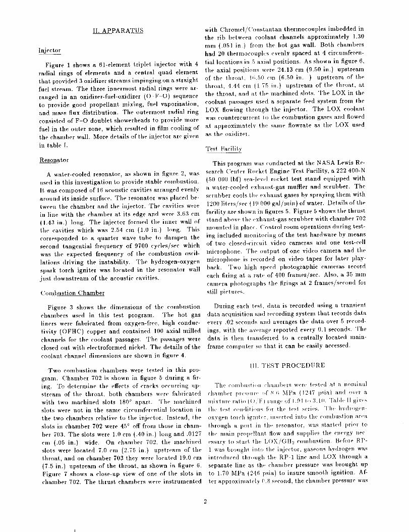
TABLE I. - INJECTOR GEOMETRYOF 61-ELEMENT INJECTOR WITH TRIPLET OXYGEN-FUEL-OXYGEN
TANGENTIAL LIQUID OXYGEN FANS
Hole diameter, mm (in.)
Outerzone
Core
zone
Centerzone
Flow area, mm2 (in.21
Outer
zone,24 holes
Core
zone,
36 holes
Center
zone,1 hole
Totalflow
area,
mm2(in. 2 )
Portionof totalflow inouter
zone,percent
Nominal
chamberpressure,
Pc,MPa abs
(psia)
Fuel element
1.168 1.600 1,600 25.715 72,382 2.011 lO0.1l] 25.7 8.6(0,046) (0.063) (0.063) (0,040) (0.112) (0,0031) (0.155]) (1247)
Oxidizer element
]3.21.168(0.046)
1.702 1.397 25.735(0.067) (0.055) (0.040)
163.74 4.581(0.254) (0.0071)
194.05(0.30]l)
8.6(12471
TABLE II. - TEST CONDITIONS
Run
2225
32
3334
3536
3738
Englne
MPa abs
702 8.329
702 7.963
703 8.274703 8.542703 8.598
703 8.556
703 8.618703 8.687703 8.777
Nomlnal chamber
pressure, Pc
psla
1208
I1551200
12391247
1241
12501260
1273
Mixture
ratio,OIF
2.71a3.lO
2.582.782.722.331.912.102.18
Coolant flow rate
kglsec Ibmlsec
12.0 26.5]4.7 32.414.1 3l .l14.4 31.8
14.3 31.5
14.2 31.213.9 30.7
13.4 29.513.6 30.0
aAverage for the entire run.
Run
time,sec
l.Ol.O1.01.01.0
l.O1.0
.61.0
FIGURE I. - G1 ELEMENTTRIPLETINJECTOR.
-85-1960
ORIGINAL PAGE
BLACK AND W,l-411lE PHL)TOGRAPI4

FIGURE 2. - ACOUSIIC RESONATOR.
CHAMBER DIAMETER
12,2 CM (q.8 IN.)
2.54 CM (1.0 IN,) 1
INJECTOR FACE _ I I 5/. I!>cM
IN_CTOR_ODY-"--I "_,l." i
/ il li 1
os. J....CAVITY .... _ :[
// _'-1G.5 CM (1_,5 IN.)/ CYLINDRICAL SEC] ION
RESONATOR BODY -"
IGNITER PORI J
FIGURE 3. - COMBUSTION CHAMBER DIMENSIONS.
IHROA] DIA._ETER
6.6 CM (2.6 IN,) EXII DIAMETER
15.9 CM (6.26 IN.)
¢_
ORIGINAL PAGE
BLACK AND WHITE PHOTO_RAP.H

•20 --
,15 --
o .I0 --
.05 --
0 q
5 --
4 --
I
o-28
t
!,_lw I"
"X
m
I
/I
/I
//
\
I t I [ I 1 I 1 I I I-24 20 -IG -12 8 q 0 q 8 12 IG
AXIAL I)ISIANCEFROM THROAT, CM
L I 1 I I I I I I-10 8 -G -q 2 0 2 4 G
AXIAL DISIANCE FROMTHROAT, IN,
FIGURE 4. CH/VIB_RWALL AND CHANNEL DIMENSIONS.
W
t
12O
17
FIGURE 5. - CHAMBER DURING TEST FIRING•
C-89-01775
ORIQ!NAL PAGE"
BLACK AND '_'f-':,'!T_:]P_tOTOGF_Ap_#'
4z
2
o
._ -2
-4 --
__ _ -4 --
8-12
THERMOCOUPLE LOCAi IONS
SLOT LOCAl IONS[IIROAI
L___I I I I I I I I I__3....-_ ] I I I40 36 -32 28 -24 -20 -16 12 8 _ {) q 8 12 16 20
CM
L I I I I I I I L 1 I I I-16 -14 -12 -10 -8 _6 q 2 0 ? q 6 8
IN.
FIGURE G. - SLOT AND THERMOCOUPLI lOCAtION,q,
FIGURE 7. - CLOSE-UP VIEW Ol MACHINtD Slr_i.
ORIGINAL PAGE
BLACK AND WHITE PHOTOGRAPF[

ORIGINAl.. PAGEBLACK AND WHITE PHOTOGRAPH
FIGURE 9. - CHAMBER702 AFTER TESTING.
9
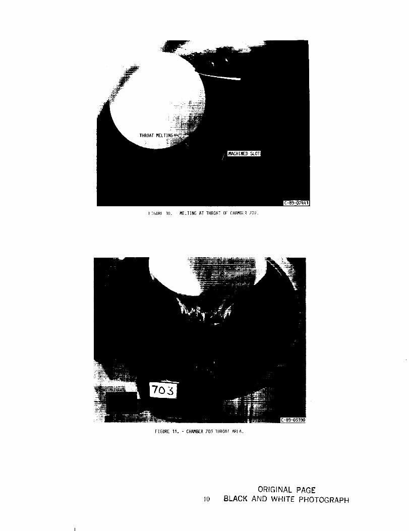
FIGURE 10. - MELTING AT THROAT Of CHAMBiR 702.
FIGURE 11. - CHANBER 703 IHROAT AREA.
I0
ORIGINAL PAGE
BLACK AND WHITE PHOTOGRAPH

FIGURE 12. - CHAMBER 703 AFTER TESTING.
FIGURE 13. - MELTED THROAT REGION OF BOTH CHAI4BERS.
ORIGINAL" PAGE'
BLACK AND WHITE PHOTOGRAPH
l!
_e
tO0
99
98
97
96
95
94
93--
92--
91P
901.9
CH/V__RS
0 CRACKED,BEFORERELTII_[] [] CRACKED, AFTER MELTING
UNCRACKED
[]
0
0
0
0
0
I I I I I I2.1 2.3 2.5 2.7 2.9 3.1
MIXTURE RATIO, O/F
FIGURE lq. - CHARACTERISTIC EXHAUST VELOCITY EFFICIENCY FOR A CHAMBER PRESSURE
OF 8.G MPA.
SO --
49 --
48 --
47 --
q5--
44--
q31.9
[][]
0 BEFORE MELTING
[] AFTER MELTING
[]0 0
00
I I I I I _P2.1 2.5 2.5 2.7 2.9 3.1
MIXTURE RATIO, O/F
FIGURE 15. - THRUST LEVEL FOR A CHAMBER PRESSURE OF 8.6 P@A (1250
PS]A).
12
1200
1100
IOO0
9OO
80O
6OO
700--
-- 600--
__ 5OO--
_=_2=< _oo--
500 -- 300 I
2001.9
300--
LOCATIONS
rl A, #703 0I% A, #702
O B, #703<> C, #703
0 C, #702
A D, #703 O
$7 O, #702
O
013 [] D
o0 _ 0
f I J2.1 2.3 2.5 2.7
MIXTURE RATIO, O/F
F]GURE 16. - HOT GAS WALL TEF_ERATURES,AT X = #.44 CM.
I2.9
E
I].1
7OO
900
7OO
600
1200_
1100 -- 600
1000--
-- 500
300500--
q00--
300 --
200 L.
10o1,9
LOCATION
[] A, #7031% A, #702
0 B, #703
0 B, #702
O C, #703
O C, #702A D, #703
_7 D, #702
0
o
o oD
°° o o _8
o
I I I I I2.1 2.3 2.5 2.7 2.9
RIXTURE RATIO, O/F
FIGURE 17. - HOT GAS WALL TEI_ERATURES AT X = 16.5 CM.
0
I3.1
13

Report Documentation PageNational Aeronautics andSpace Administration
1. Report No. NASA TM-102113 2. Government Accession No. 3. Recipient's Catalog No.
AIAA 89-2739
5. Report Date4. Title and Subtitle
Liquid Oxygen Cooling of Hydrocarbon Fueled Rocket Thrust Chambers
7. Author(s)
Elizabeth S. Armstrong
9. Performing Organization Name and Address
National Aeronautics and Space AdministrationLewis Research Center
Cleveland, Ohio 44135-3191
12. Sponsoring Agency Name and Address
National Aeronautics and Space Administration
Washington, D.C. 20546-0001
6. Performing Organization Code
8 Performing Organization Report No.
E-4886
10 Work Unit No.
582-01-21
il Contract or Grant No.
it3. Type of Report and Period Covered
Technical Memorandum
14. Sponsoring Agency Code
15. Supplementary Notes
Prepared for the 25th Joint Propulsion Conference cosponsored by the AIAA. ASME, SAE, and ASEE,
Monterey, California, July 10-12, 1989.
16. Abstract
Rocket engines using liquid oxygen (LOX) and hydrocarbon fuel as the propellants are being given serious con-sideration for future launch vehicle propulsion. Normally, the fuel is used to regeneratively cool the combustion
chamber. However, hydrocarbons such as RP-1 are limited in their cooling capability. Another possibility for the
coolant is the liquid oxygen. Combustion chambers previously tested with LOX and RP-1 as propellants and LOX
as the coolant have demonstrated the feasibility of using liquid oxygen as a coolant up to a chamber pressure of
13.8 MPa (2000 psia). However, there has been concern as to the effect on the integrity of the chamber liner if
oxygen leaks into the combustion zone through fatigue cracks that may develop between the cooling passages and
the hot gas side wall. In order to study this effect, chambers were fabricated _ith slots machined upstream of the
throat between the cooling passage wall and the hot gas side wall to simulate cracks. The chambers were tested
at a nominal chamber pressure of 8.6 MPa (1247 psia) over a range of mixturc ratios from 1.9 to 3.1 using
liquid oxygen as the coolant. The results of the testing showed that the leaking LOX did not have a deleterious
effect on the chambers in the region of the slots. However, there was unexplained melting in the throat region of
both chambers, but not in line with the slots. Thermocouple readings did not give conclusive evidence of when
the melting began.
17. Key Words (Suggested by Author(s))
Rocket engine cooling; LOX cooling; Hydrocarbon;Kerosene; Rocket engine
18. Distribution Statement
Unclassified - Unlimited
Subject Category 20
19. Security Classif. (of this report) 20. Security Classif. (of this page) ! 21. No of pages
Unclassified Unclassified [ 14I
NASAFORMle2eoct 86 *For sale by the National Technical Information Service, Springfield. Virginia 22161
22. Price*
A03
Related Documents