DOE/EM-0392 Liquid Nitrogen- Cooled Diamond- Wire Concrete Cutting Deactivation and Decommissioning Focus Area Prepared for U.S. Department of Energy Office of Environmental Management Office of Science and Technology December 1998

Welcome message from author
This document is posted to help you gain knowledge. Please leave a comment to let me know what you think about it! Share it to your friends and learn new things together.
Transcript
DOE/EM-0392
Liquid Nitrogen-Cooled Diamond-
Wire ConcreteCutting
Deactivation and DecommissioningFocus Area
Prepared for
U.S. Department of EnergyOffice of Environmental Management
Office of Science and Technology
December 1998
LiquidNitrogen-
CooledDiamond-Wire
ConcreteCutting
OST Reference #2107
Deactivation and DecommissioningFocus Area
Demonstrated atHanford Site
Richland, Washington

Purpose of this document
Innovative Technology Summary Reports are designed to provide potential users with theinformation they need to quickly determine if a technology would apply to a particularenvironmental management problem. They are also designed for readers who mayrecommend that a technology be considered by prospective users.
Each report describes a technology, system, or process that has been developed and testedwith funding from DOE’s Office of Science and Technology (OST). A report presents the fullrange of problems that a technology, system, or process will address and its advantages to theDOE cleanup in terms of system performance, cost, and cleanup effectiveness. Most reportsinclude comparisons to baseline technologies as well as other competing technologies.Information about commercial availability and technology readiness for implementation is alsoincluded. Innovative Technology Summary Reports are intended to provide summaryinformation. References for more detailed information are provided in an appendix.
Efforts have been made to provide key data describing the performance, cost, and regulatoryacceptance of the technology. If this information was not available at the time of publication,the omission is noted.
All published Innovative Technology Summary Reports are available on the OST Web site athttp://ost.em.doe.gov under “Publications.”

TABLE OF CONTENTS
1
2
3
4
5
6
7
A
B
C
SUMMARY page 1
TECHNOLOGY DESCRIPTION page 5
PERFORMANCE page 8
TECHNOLOGY APPLICABILITY AND page 14ALTERNATIVE TECHNOLOGIES
COST page 15
REGULATORY AND POLICY ISSUES page 19
LESSONS LEARNED page 20
APPENDICES
References
Cost Comparison
Acronyms and Abbreviat ions

Page 1 U.S. Department of Energy
SUMMARY
SECTION 1
Liquid Nitrogen-Cooled Diamond-Wire Concrete Cutting can be used to cut through thick concrete walls, floors,and structures without using water to cool the cutting wire. The diamond wire is cooled with liquid nitrogen in a0.9-m (3-ft) long by 7.6-cm (3-in.) diameter pipe housing. The nitrogen evaporates, so no contaminated liquidwaste is generated. Other than the use of liquid nitrogen, the system is a conventional diamond-wire sawassembly with remote hydraulic controls. Setup of the hydraulic-powered drive wheel and the diamond wire forcutting requires a relatively short period of time using people with minimal training. Concrete dust generatedduring the cutting is considerable and requires control. The production rate of this improved technology is0.78 m2/hr (8.4 ft2/hr). The production rates of traditional (baseline) water-cooled diamond-wire cutting andcircular saw cutting technologies are 1.11 m2/hr (12 ft2/hr), and 0.45 m2/hr (4.8 ft2/hr), respectively. The liquidnitrogen-cooled system costs 189% more than conventional diamond-wire cutting if contaminated liquid wastescollection, treatment, and disposal are not accounted for with the baseline. The new technology was 310%more costly than a conventional diamond circular saw, under the conditions of this demonstration (nowastewater control). For cutting a 0.9-m x 3.7-m (3-ft x 12-ft) wall, the improved technology costs $17,000,while baseline diamond-wire cutting would cost $9,000 and baseline circular-saw cutting would cost $5,500. The improved system may cost less than the baseline technologies or may be comparable in cost if wastewatercontrol is included.
ss Technology Su mmary
The liquid nitrogen-cooled diamond-wire concrete cutter is an improved technology designed and fabricated byBluegrass Concrete Cutting, Inc., of Greenville, Alabama. This improved technology was demonstrated for theU.S. Department of Energy's (DOE) C Reactor Interim Safe Storage (ISS) Project as part of the Large-ScaleDemonstration and Deployment Project (LSDDP) at the DOE's Hanford Site in Washington.
Diamond-wire cutting has been used traditionally with water injected into the kerf for cooling and dust control. Liquid nitrogen is a desirable alternative cooling agent for concrete sawing because the nitrogen evaporates,leaving no potentially contaminated liquid waste. In this demonstration, a 0.9-m (3-ft) long by 7.6-cm (3-in.)diameter pipe housing was installed around the diamond wire, into which liquid nitrogen was sprayed. Liquidnitrogen is available in portable Dewar tanks from commercial welding gas dealers.
The diamond wire is made of a 6.4-mm (0.25-in.) aircraft-quality steel cable with diamond-impregnated beads. Each diamond-impregnated bead is separated from the next by a spring, and three-bead/spring combinationsare each separated by a 3,629-kg (8,000-lb) pressure brass crimp.
A 50-hp hydraulic pump drives a hydraulic motor that powers the diamond-wire saw-drive wheel. The 0.9-m (3-ft) diameter drive wheel generates wire tension and moves the diamond wire as fast as 25 m/sec (82 ft/sec). Speed and tension on the diamond-wire saw are controlled remotely by adjusting a cylinder valve and a needlevalve on the hydraulic pump.
Problem Addressed
The liquid nitrogen-cooled diamond-wire concrete cutting was assessed in an effort to find ways of eliminatingcooling water from the conventional cutting process. With baseline concrete cutting technologies, the portionof water that does not evaporate forms a slurry with concrete dust that must be managed as a waste product. If the concrete is radiologically contaminated, the waste slurry must be captured, treated, and disposedappropriately. Dry cutting may be preferred, and the concrete dust can be collected with a vacuum filtrationsystem.
Features and Configuration
The improved technology uses the following components:
SUMMARY continued
Page 2 U.S. Department of Energy
& An electric/hydraulic power unit requiring 60-amp, 3-phase, 480-volt current. The unit is 0.8 m (32 in.)wide, 1.5 m (60 in.) long, and 1.2 m (48 in.) high. The hydraulic pump is rated at 129 L/min (34 gal/min)and 207 bars (3,000 psi). The unit weighs 680 kg (1,500 lb) and has lifting hooks and forklift guides.
& A hydraulically powered drive wheel, 0.9 m (3 ft) in diameter. The drive wheel can be located up to 30.1 m(100 ft) away from the electric/hydraulic power unit. The drive wheel unit and guide pulleys weigh lessthan 90 kg (200 lb). The hydraulic system uses once-through cooling water that does not becomecontaminated.
& A diamond-wire saw with a pipe housing added; the length of diamond wire depends on the size of cut.
The equipment is easy to set up; however, the saw and wire must be housed in a temporary enclosure that isexhausted via a vacuum filtration system. Pre-drilled holes are required to string the diamond-wire saw aroundor through the concrete structure being cut.
Potential MarketslA pplicability
The liquid-nitrogen cooled diamond-wire concrete cutting technology is useful at DOE, U.S. EnvironmentalProtection Agency (EPA), or U.S. Nuclear Regulatory Commission (NRC) sites where contaminated concretemust be cut as part of a demolition process, especially where use of water is undesirable. The technology couldbe used at other public or commercial facilities where concrete cutting is required.
Advantages of the Improved Technology
& The technology can be used to cut almost any engineered concrete structure (walls and floors of nearlyany size).
& Using liquid nitrogen for cooling the diamond-wire eliminates the use of cooling water that could becomecontaminated; however, dust must be controlled with an adequately sized HEPA vacuum filtration unit. The use of smaller amounts of water to control dust than with baseline tools may be favorable in somecases.
& Adequate dust collection must be compared to the use of cooling water for each project. An engineeringevaluation would determine if dust collection is more economical than slurry collection.
The following table summarizes the advantages and shortfalls of the improved technology compared to thewater-cooled baseline technologies (diamond-wire saw cutter and a diamond circular saw).
Category Comments
Cost More expensive than the baseline technologies. (For a wall 0.9-m [3-ft] thick and3.7-m [12-ft] high, the costs are $17,000, $9,000, and $5,500 for the improved,water-cooled diamond wire, and water-cooled circular saw technologies,respectively.) A major cost component is a tent enclosure to control dustemissions, which is not needed with the baseline technologies; costs depend ondust control and contaminated wastewater handling.
Performance Cutting rate is 70% as fast as the water-cooled diamond wire, but 75% faster thanthe use of a circular saw.
Implementation Does not require capture of wastewater slurry.
Secondary Waste Dry waste can be handled easier than wastewater slurry.
ALARA/Safety Can control cutting 30 m (100 ft) away from a potential radiation source.
SUMMARY continued
Category Comments
Page 3 U.S. Department of Energy
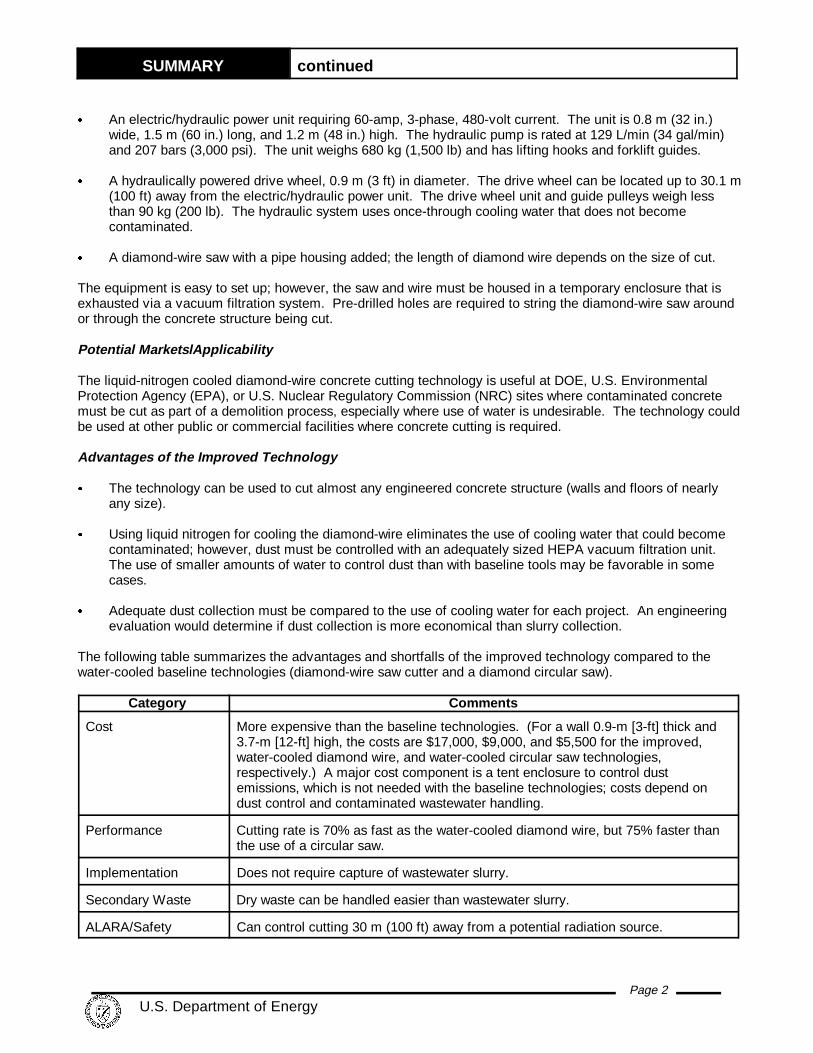
Figure 1. Diamond wire and cut line .
Ease of Use/Training Easy operation by an operator experienced in diamond-wire cutting; not as easy tolearn as the baseline circular saw.
Operator Concerns
The dust generated requires the use of a dust-control technology. A high-capacity high-efficiency particulate air(HEPA) filter was used for this demonstration; standard commercial filters could be used for non-contaminatedsites. A small amount of water could also be used to control dust, but this concept was not evaluated. If thewire breaks during operations, whiplash can occur behind the saw.
Skills and Training
As with any diamond-wire saw, special operator experience is needed to properly control the wire tension.
ss Demonstration Su mmary
Liquid nitrogen-cooled diamond-wire concrete cutting was demonstrated by the Hanford Site C ReactorTechnology Demonstration Group during March 1998.
Demonstration Site Description
Liquid nitrogen-cooled diamond-wire concrete cutting wasdemonstrated for the first time by the DOE at its Hanford Site. A concrete wall at the C Reactor was cut to separate a sectionof the wall that is to remain standing from a section to bedemolished. See Figure 1. The section remaining is part ofthe outside of the reactor safe storage enclosure (SSE).
Regulatory Issues
There are no special regulatory or permit requirementsassociated with implementation of this technology. Normalworker safety practices should be applied when using this toolin accordance with applicable regulations, particularly10 Code of Federal Regulation (CFR), Parts 20, 835, andproposed Part 834, to protect workers and the environmentfrom radiological contaminants; and 29 CFR OccupationalSafety and Health Administration (OSHA) worker requirements.
Technology Availability
The system is readily available through Bluegrass Concrete cutting, Inc., Greenville, Alabama.
Technology Limitations/ Needs for Future Deve lopment
& As presently designed and operated during the demonstration, the area that can be cut with the improvedtechnology is limited to 2.5 m2 (27 ft2). Overheating and wire damage occurs beyond this point.
& Immersing the diamond-cutting cable in liquid nitrogen and/or injecting some of the liquid nitrogen into thekerf could be investigated for system improvements.
& A combination of liquid nitrogen cooling and minimal water injection for dust control could be developed toimprove dust collection and cutting performance.

SUMMARY continued
Page 4 U.S. Department of Energy
& Unless special ventilation is used, indoor use of the liquid nitrogen-cooled saw is limited because of thenitrogen gas produced, which displaces oxygen in enclosed areas. (The demonstration was at an outdoorarea.)
ss Contacts
ManagementJohn Duda, FETC, (304) 285-4217Jeff Bruggeman, DOE-RL, (509) 376-7121Shannon Saget, DOE-RL, (509) 372-4029
Technical InformationStephen Pulsford, BHI, (509) 375-4640 Gregory Gervais, USACE, (206) 764-6837Robert Hulick, Bluegrass Concrete Cutting, Inc., (800) 320-1462
LicensingNick Jenkins, Bluegrass Concrete Cutting, Inc., (800) 320-1462
OtherAll Published Innovative Technology Summary Reports are available at http://em-50.em.doe.gov. TheTechnology Management System, also available through the EM50 Web site, provides information about Officeof Science and Technology (OST) programs, technologies, and problems. The OST Reference Number forLiquid Nitrogen-Cooled Diamond-Wire Concrete Cutting is 2107.
Page 5 U.S. Department of Energy
TECHNOLOGY DESCRIPTION
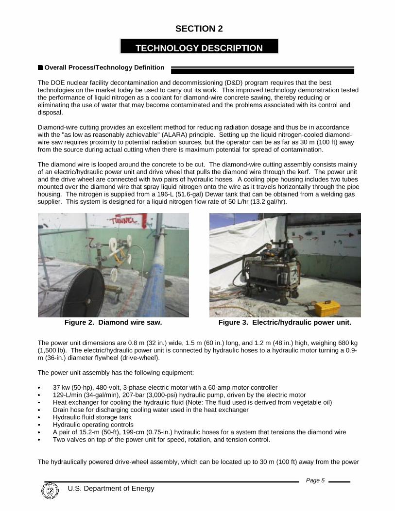
Figure 2. Diamond wire saw. Figure 3. Electric/hydraulic power unit.
SECTION 2
ss Overall Process/Tec hnology Definition
The DOE nuclear facility decontamination and decommissioning (D&D) program requires that the besttechnologies on the market today be used to carry out its work. This improved technology demonstration testedthe performance of liquid nitrogen as a coolant for diamond-wire concrete sawing, thereby reducing oreliminating the use of water that may become contaminated and the problems associated with its control anddisposal.
Diamond-wire cutting provides an excellent method for reducing radiation dosage and thus be in accordancewith the "as low as reasonably achievable" (ALARA) principle. Setting up the liquid nitrogen-cooled diamond-wire saw requires proximity to potential radiation sources, but the operator can be as far as 30 m (100 ft) awayfrom the source during actual cutting when there is maximum potential for spread of contamination.
The diamond wire is looped around the concrete to be cut. The diamond-wire cutting assembly consists mainlyof an electric/hydraulic power unit and drive wheel that pulls the diamond wire through the kerf. The power unitand the drive wheel are connected with two pairs of hydraulic hoses. A cooling pipe housing includes two tubesmounted over the diamond wire that spray liquid nitrogen onto the wire as it travels horizontally through the pipehousing. The nitrogen is supplied from a 196-L (51.6-gal) Dewar tank that can be obtained from a welding gassupplier. This system is designed for a liquid nitrogen flow rate of 50 L/hr (13.2 gal/hr).
The power unit dimensions are 0.8 m (32 in.) wide, 1.5 m (60 in.) long, and 1.2 m (48 in.) high, weighing 680 kg(1,500 lb). The electric/hydraulic power unit is connected by hydraulic hoses to a hydraulic motor turning a 0.9-m (36-in.) diameter flywheel (drive-wheel).
The power unit assembly has the following equipment:
& 37 kw (50-hp), 480-volt, 3-phase electric motor with a 60-amp motor controller& 129-L/min (34-gal/min), 207-bar (3,000-psi) hydraulic pump, driven by the electric motor& Heat exchanger for cooling the hydraulic fluid (Note: The fluid used is derived from vegetable oil)& Drain hose for discharging cooling water used in the heat exchanger& Hydraulic fluid storage tank& Hydraulic operating controls& A pair of 15.2-m (50-ft), 199-cm (0.75-in.) hydraulic hoses for a system that tensions the diamond wire& Two valves on top of the power unit for speed, rotation, and tension control.
The hydraulically powered drive-wheel assembly, which can be located up to 30 m (100 ft) away from the power
TECHNOLOGY DESCRIPTION continued
Page 6 U.S. Department of Energy
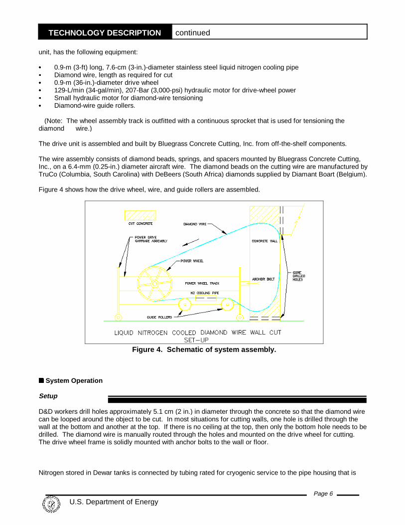
Figure 4. Schematic of system assembly.
unit, has the following equipment:
& 0.9-m (3-ft) long, 7.6-cm (3-in.)-diameter stainless steel liquid nitrogen cooling pipe& Diamond wire, length as required for cut& 0.9-m (36-in.)-diameter drive wheel& 129-L/min (34-gal/min), 207-Bar (3,000-psi) hydraulic motor for drive-wheel power& Small hydraulic motor for diamond-wire tensioning& Diamond-wire guide rollers.
(Note: The wheel assembly track is outfitted with a continuous sprocket that is used for tensioning thediamond wire.)
The drive unit is assembled and built by Bluegrass Concrete Cutting, Inc. from off-the-shelf components.
The wire assembly consists of diamond beads, springs, and spacers mounted by Bluegrass Concrete Cutting,Inc., on a 6.4-mm (0.25-in.) diameter aircraft wire. The diamond beads on the cutting wire are manufactured byTruCo (Columbia, South Carolina) with DeBeers (South Africa) diamonds supplied by Diamant Boart (Belgium).
Figure 4 shows how the drive wheel, wire, and guide rollers are assembled.
ss System Operation
Setup
D&D workers drill holes approximately 5.1 cm (2 in.) in diameter through the concrete so that the diamond wirecan be looped around the object to be cut. In most situations for cutting walls, one hole is drilled through thewall at the bottom and another at the top. If there is no ceiling at the top, then only the bottom hole needs to bedrilled. The diamond wire is manually routed through the holes and mounted on the drive wheel for cutting. The drive wheel frame is solidly mounted with anchor bolts to the wall or floor.
Nitrogen stored in Dewar tanks is connected by tubing rated for cryogenic service to the pipe housing that is

TECHNOLOGY DESCRIPTION continued
Page 7 U.S. Department of Energy
Figure 5. Cooling pipe housing forapplying liquid nitrogen to thediamond wire.
mounted between the drive wheel and the wall being cut. At the remote hydraulic control unit, a source ofcooling water, approximately 19 L/min (5 gal/min), is connected to the hydraulic fluid heat exchanger. (Coolingwater discharged from this heat exchanger is not contaminated.)
The drive wheel unit with tensioning track, pulleys, and diamond wire must be in an enclosure to containconcrete dust generated from the kerf. For the demonstration, a three-sided tent-type structure was set upagainst the wall. Air and vaporized nitrogen were exhausted from one side of the tent with a vacuum HEPAfiltration unit. Makeup air was admitted on the other side through two openings. The air flow path was suchthat air flowed across the saw system components and minimized the amount of concrete dust that settled onthe components.
If the wire breaks while operating, it can whiplash back into the area outside of the enclosure behind the endopposite the concrete wall. A plywood board was secured behind this end to contain a potential whiplash, andthe area was barricaded to preclude pedestrian traffic within approximately 6 m (20 ft) behind the board.
After the diamond wire is threaded into place, the location where the wire protrudes at the other side of the wallis enclosed with temporary plastic and/or wooden boards. This contains dust that might otherwise becomeairborne on the far side of the wall.
Operation
When the wire has been installed, the operator starts the electricmotor on the remote hydraulic control power unit and then tensionsthe diamond wire before cutting. With a system hydraulic pressureof 100 to 150 bars (1,450 to 2,175 psi), the wire speed isapproximately 25 m/sec (82 ft/sec). The diamond wire is cooled by50 L (13.2 gal) of liquid nitrogen per hour as it passes through thestainless steel cooling pipe housing. Inside the pipe housing, theliquid nitrogen from a pressurized Dewar tank is applied from tubingat two points above the diamond wire as the wire travels through thepipe housing. Figure 5 shows the pipe housing. Insulating spiralsteel brushes are mounted within the cooling pipe housing to limitloss of nitrogen through the two openings.
The diamond wire is tensioned by a small hydraulic motor thatengages a continuous sprocket mounted on the flywheel track. Thecutting operation continues until the drive wheel reaches the end ofthe diamond-wire tensioning track, at which point the drive wheel requires restroking. Restroking isaccomplished by manually resetting the drive wheel to the beginning of the tensioning track, cutting out theappropriate length of the diamond wire, and resplicing the wire. Restroking is required every time thetensioning track is at the end. The track assembly is mounted with bolted anchors at the concrete wall forstability.
As the cutting operation proceeds, a large amount of fine concrete dust is generated. For this demonstration acomplete temporary tent-type atmospheric enclosure was constructed to contain and collect the dust. Theexhaust port of the enclosure was connected to a HEPA vacuum filtration system. The breathing air in theenclosure must be checked before anyone enters to restroke the assembly because the nitrogen displaces airas it vaporizes, causing the oxygen levels to fall. Technicians operating the equipment do not normally wearrespiratory protection. However, oxygen monitoring and respiratory protection for dust were required whenentering the enclosure.

Page 8 U.S. Department of Energy
PERFORMANCE
SECTION 3
ss Demonstration Plan
Site Description
At its former weapons production sites, DOE's Office of Science & Technology/Deactivation andDecommissioning Focus Area, in collaboration with the Environmental Restoration Program, is conducting anevaluation of improved technologies that might prove valuable for facility D&D projects. As part of the HanfordSite LSDDP, at least 20 technologies are being demonstrated and assessed against baseline technologiescurrently in use. If successfully demonstrated at the Hanford Site, these improved technologies could beimplemented at other DOE sites and similar government or commercial facilities.
The demonstration described in this report was conducted by Bechtel Hanford, Inc., the DOE's EnvironmentalRestoration Contractor responsible for the D&D program at the Hanford Site. One objective of the LSDDP is toshow how to use commercially available, and recently developed technologies to place Hanford's C Reactorinto an ISS mode for up to 75 years, or until the final disposal of the reactor's core is completed. The CReactor ISS objectives include placing the reactor in a condition that will not preclude or increase futuredecommissioning costs, but will minimize the potential for releases to the environment and reduce thefrequency of inspections, thereby reducing potential risk to workers.
Nuclear facilities undergoing D&D are typically chemical and/or radiologically contaminated. To support thisD&D work, the DOE sometimes requires tools for cutting concrete in places where water cannot be used forcooling the saw cutters. The tool must be easy and economical to operate, capable of operating in a widerange of ambient temperatures, and easy to decontaminate with conventional equipment. The tool must alsobe safe for workers. The liquid nitrogen-cooled diamond-wire saw satisfies these needs and is an alternative totraditional technologies used for cutting concrete.
At the C Reactor, concrete structures attached to the safe storage enclosure (SSE) must be cut away. TheSSE contains the reactor block and consists of the reactor shield walls and a new roof. Abutting walls aresegmented from the shield walls and then demolished. The improved and baseline technologies weredemonstrated on the following 0.91-m (3-ft)-thick concrete walls that abutted the SSE walls:
ImprovedTechnology Nitrogen-Cooled Diamond Wire
BaselineTechnology Water-Cooled Diamond
Wire
Baseline TechnologyWater-CooledCircular Saw
Height of wall 3.66 m (12 ft) 3.66 m (12 ft) 12.2 m (40 ft)
Face area of cut 3.2 m2 (36 ft2) 3.2 m2 (36 ft2) 11.1 m2 (120 ft2)
Fraction of areaactually cut
3/4 All 2/3
Area actually cut 2.5 m2 (27 ft2) 3.2 m2 (36 ft3) 7.4 m2 (80 ft2)
All of the walls involved were heavily reinforced with steel bars within approximately 6 cm (2.5 in.) of thesurface. The walls cut with diamond-wire technologies were not within radiologically contaminated areas of theC Reactor complex. In this situation, water runoff associated with the diamond-wire technologies did not haveto be completely collected and treated for disposal. The wall cut with the diamond circular saw wascontaminated on one side.
PERFORMANCE continued
Page 9 U.S. Department of Energy
Performance Objectives
The objectives of the demonstration include evaluating the following desired capabilities and design featuresfor the equipment:
A. Can cut structural concrete up to 1.2 m (4 ft) thickB. Is easily decontaminated with conventional equipmentC. Operates in ambient temperature environments from 3 to 40(C (37 to 104(F)D. Minimizes secondary waste generation, especially liquid waste that may become
contaminatedE. Ability to use a HEPA vacuum filtration unit for any airborne particulates generated.
Demonstration Chronology
The demonstration was conducted mainly during March 1998 on walls 0.9 m (3 ft) thick at the Hanford Site CReactor building complex. The walls were identified for demolition and had to be segmented from the mainstructure, which is to remain standing for ISS. Maintaining integrity of the SSE walls is vital. Saw cutsbetween walls being demolished and the walls of the SSE were required because steel reinforcing bars connectthese concrete structures.
Improved Technology
The tent enclosure for concrete dust containment was set up before the nitrogen-cooled system arrived on site. Liquid nitrogen for this demonstration was obtained from a local welding equipment supplier shortly before theday of the demonstration.
Baseline Technologies
The improved technology was evaluated against two baseline technologies. One baseline technology is thesame diamond-wire system that the improved technology uses, but cooled with water instead of liquid nitrogen. The other is a typical diamond-tipped circular saw on a wall-mounted track. The circular saw technology is thetypical diamond-tipped round saw blade placed on the shaft of a hydraulic motor, which is mounted on a trackfor operation.
Both the circular saw and diamond wire are driven by hydraulic motors, and water for cooling and dust controlis applied in the kerf. Diamond-wire cuts are made with the drive system and tensioning system set up onceonly on one side of the concrete structure, and the wire is pulled through as it travels. Unless very large-diameter blades are used, circular saw cuts can be accomplished with partial-depth cuts made from each of thetwo sides of the concrete structure, as was done at this site.
The water-cooled diamond-wire cut was made the day after the nitrogen-cooled system was demonstrated. The water-cooled diamond circular saw cuts were made approximately a month after the diamond-wire cuts.
ss Technology Demonstration Results
Key Demonstrat ion Results
& Liquid nitrogen can be used as a cooling medium for diamond-wire cutting of thick reinforced concretestructures.
& No potentially contaminated liquid waste was generated.& Cuts 30% slower than a conventional water-cooled diamond-wire saw, but 75% faster than a conventional
water-cooled diamond circular saw. Reduced production rate compared to water-cooled diamond-wirecutting is attributed to concrete dust buildup in the kerf that could be contaminated.
PERFORMANCE continued
Page 10 U.S. Department of Energy
& Using liquid nitrogen for cooling the diamond-wire eliminates the use of cooling water that could becomecontaminated; however, dust must be controlled with an adequately sized HEPA vacuum filtration unit. The use of smaller amounts of water than with baseline tools to control dust may be an option in somecases.
& Adequate dust collection must be evaluated against the use of cooling water for each project. Anengineering evaluation can determine if dust collection is more economical than slurry collection.
& The diamond wire can be quickly installed, and the operator can be remote from the contaminatedstructures being cut.
& The diamond beads on the liquid nitrogen-cooled wire showed increased wear compared to the water-cooled diamond wire.
& The bead-tensioning springs in the wire assembly showed discoloration caused by elevated temperaturesduring later stages of cutting the first wall. Liquid nitrogen cooling was stopped when approximately 75%of the first wall cut was completed, because the cutting rate would have been slowed down further toprevent damage to the wire caused by overheating.
Successes
& Can reduce or eliminate potentially contaminated wastewater& Quick to install& Can be operated remotely& Produces smooth cut.
Shortfalls
& Dust control may require an atmospheric enclosure& Cutting rate is slower than with a water-cooled wire, and the area of cut is limited& Diamond wire shows increased wear compared to baseline diamond wire.
Meeting Perfo rmance Objectives
The technology demonstrated that liquid nitrogen can be used as an alternative to water cooling for performingreinforced concrete cutting with a diamond-wire cutting system. The results of the performance objectiveevaluation are as follows, with respect to the performance objectives listed in the Demonstration Objectivesection:
Item A (cut structural concrete up to 1.2 m [4 ft] thick) was demonstrated on walls that were 0.9 m (3 ft) thickusing a conventional diamond-wire saw system to which a liquid nitrogen cooling apparatus had been added. The system is designed for cutting structures thicker than 1.2 m (4 ft); the vendor has successfully tested theequipment on 1.2-m (4-ft)-thick concrete.
Item B (equipment easily decontaminated) was not checked in the field because the saw system was used onlyon non-contaminated concrete walls. The hydraulic power and control unit can be remotely located in a cleanenvironment and is normally not subject to contamination. The saw components are designed so that they canbe cleaned by conventional means and surveyed, except for the diamond wire, which is disposable.
Item C (operable at 3 to 40(C [37 to 104(F]) was not checked in the field, but all components are designed sothat they can operate in the specified temperature range.
Item D (minimizes secondary waste, especially potentially contaminated liquid waste) was demonstrated in thatonly dry dust from a 9.5-mm (0.37-in.) wide kerf was generated.
Item E (use with a HEPA vacuum filtration unit) was demonstrated using a tent enclosure, with vacuum HEPA
PERFORMANCE continued
Page 11 U.S. Department of Energy
filter units, furnished and erected by onsite D&D workers. The first filtration unit used did not have sufficientfilter capacity and was replaced.
ss Comparison of the Improved Technology to Baseline
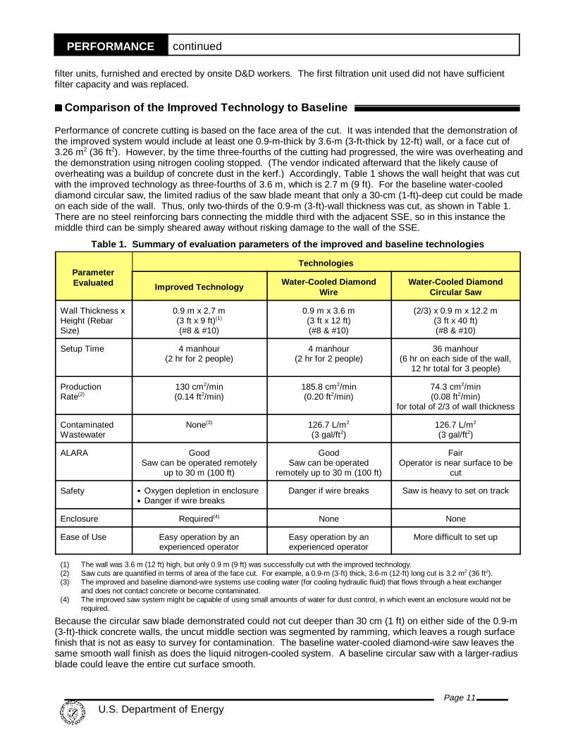
Performance of concrete cutting is based on the face area of the cut. It was intended that the demonstration ofthe improved system would include at least one 0.9-m-thick by 3.6-m (3-ft-thick by 12-ft) wall, or a face cut of3.26 m2 (36 ft2). However, by the time three-fourths of the cutting had progressed, the wire was overheating andthe demonstration using nitrogen cooling stopped. (The vendor indicated afterward that the likely cause ofoverheating was a buildup of concrete dust in the kerf.) Accordingly, Table 1 shows the wall height that was cutwith the improved technology as three-fourths of 3.6 m, which is 2.7 m (9 ft). For the baseline water-cooleddiamond circular saw, the limited radius of the saw blade meant that only a 30-cm (1-ft)-deep cut could be madeon each side of the wall. Thus, only two-thirds of the 0.9-m (3-ft)-wall thickness was cut, as shown in Table 1. There are no steel reinforcing bars connecting the middle third with the adjacent SSE, so in this instance themiddle third can be simply sheared away without risking damage to the wall of the SSE.
Table 1. Summary of evaluat ion p arameters of the improved and base line technologies
ParameterEvaluated
Technologies
Improved TechnologyWater-Cooled Diamond
WireWater-Cooled Diamond
Circular Saw
Wall Thickness xHeight (RebarSize)
0.9 m x 2.7 m(3 ft x 9 ft)(1)
(#8 & #10)
0.9 m x 3.6 m(3 ft x 12 ft)(#8 & #10)
(2/3) x 0.9 m x 12.2 m(3 ft x 40 ft)(#8 & #10)
Setup Time 4 manhour(2 hr for 2 people)
4 manhour(2 hr for 2 people)
36 manhour(6 hr on each side of the wall,
12 hr total for 3 people)
ProductionRate(2)
130 cm2/min(0.14 ft2/min)
185.8 cm2/min(0.20 ft2/min)
74.3 cm2/min(0.08 ft2/min)
for total of 2/3 of wall thickness
ContaminatedWastewater
None(3) 126.7 L/m2
(3 gal/ft2)126.7 L/m2
(3 gal/ft2)
ALARA GoodSaw can be operated remotely
up to 30 m (100 ft)
GoodSaw can be operated
remotely up to 30 m (100 ft)
FairOperator is near surface to be
cut
Safety & Oxygen depletion in enclosure& Danger if wire breaks
Danger if wire breaks Saw is heavy to set on track
Enclosure Required(4) None None
Ease of Use Easy operation by anexperienced operator
Easy operation by anexperienced operator
More difficult to set up
(1) The wall was 3.6 m (12 ft) high, but only 0.9 m (9 ft) was successfully cut with the improved technology.(2) Saw cuts are quantified in terms of area of the face cut. For example, a 0.9-m (3-ft) thick, 3.6-m (12-ft) long cut is 3.2 m2 (36 ft2).(3) The improved and baseline diamond-wire systems use cooling water (for cooling hydraulic fluid) that flows through a heat exchanger
and does not contact concrete or become contaminated.(4) The improved saw system might be capable of using small amounts of water for dust control, in which event an enclosure would not be
required.
Because the circular saw blade demonstrated could not cut deeper than 30 cm (1 ft) on either side of the 0.9-m(3-ft)-thick concrete walls, the uncut middle section was segmented by ramming, which leaves a rough surfacefinish that is not as easy to survey for contamination. The baseline water-cooled diamond-wire saw leaves thesame smooth wall finish as does the liquid nitrogen-cooled system. A baseline circular saw with a larger-radiusblade could leave the entire cut surface smooth.

PERFORMANCE continued
Page 12 U.S. Department of Energy
With liquid nitrogen-cooled cutting, concrete dust was generated, and controlling the dust was important. Thebaseline technologies use water injected into the kerf; this water provides cooling, washout of the concrete dust,and dust emissions control (so no enclosure exhausting to a vacuum HEPA filtration system is needed). Beforea concrete cutting task, the generation of cooling water secondary waste versus dust containment resulting fromliquid nitrogen cooling should be evaluated.
The nitrogen-cooled system was fully functional for approximately 2.5 m2 (27 ft2) of face cutting, after which dustbuildup in the kerf caused decreased cutting rates and increased heat. For face cuts exceeding 2.5 m2 (27 ft2),the modifications described in Section 7 (injecting liquid nitrogen and possibly water into the kerf) could beconsidered.
Because of the variety of functions and facilities, the DOE complex presents a wide range of D&D workingconditions. The working conditions for an individual job directly affect the manner in which D&D work isperformed. The improved and baseline technology comparisons presented in this report are based on a specificset of conditions and/or work practices found at the Hanford Site, as summarized in Table 2.
Table 2. Summary of variable c onditions (2 Pages)
Variable Improved Technology Baseline Technologies
Scope of Work
Location Hanford Site C Reactor Same
Nature of Work Segmenting wall Same
Work Environment
Worker Protection Level D PPE Same
Level of Contamination None Same
Work Performance
Acquisition Means Vendor-provided service Same for water-cooled and circularsaw; assumed to be site owned
Production Rates: 0.78 m2/hr (8.4 ft2/hr) Water-cooled diamond wire - 1.1 m2/hr(12 ft2/hr); Circular saw - 0.45 m2/hr(4.8 ft2/hr)
Equipment and Crew Vendor’s crew assumed to consist oftwo workers with part-time support froman industrial hygienist and part-timesupport from a D&D worker
The water-cooled diamond-wirealternative includes two vendor workersand part-time support from a D&Dworker, and the circular saw uses threeD&D workers
Work Process Steps 1) Transport personnel andequipment
2) Vendor workers undergo siteorientations and securityarrangements
3) Safety meeting4) Operate saw5) Transport personnel and
equipment back to vendor’sheadquarters
Same as the improved technology forthe water-cooled diamond-wirealternative. The circular saw processsteps are:1) Safety meeting2) Set up equipment3) Operate saw4) Demobilize equipment
Skills and Training

PERFORMANCE continued
Page 13 U.S. Department of Energy
As with any diamond-wire saw, special operator experience is needed to control the wire tension properly.
Operat ional Con cerns
The diamond wire may break while cutting. The area in the back of the diamond-wire driving wheel should havea protective shield, such as a plywood sheet, and this area should be avoided by personnel. The potential forthe wire to break increases as the wire tension is increased.
Secondary waste generation consists of fine dust generated by the diamond-wire saw. Cutting contaminatedmedia requires dust control (i.e., an enclosure to prevent the escape of radionuclides). However, it also wouldbe advisable to construct an enclosure for non-contaminated media because a large amount of dust isproduced.
Where liquid nitrogen is used in enclosed areas, personnel should not be in the enclosed areas unlessmonitoring indicates that adequate oxygen is present for breathing.
Page 14 U.S. Department of Energy
TECHNOLOGY APPLICABILITY ANDALTERNATIVE TECHNOLOGIES
SECTION 4
ss Technology Applicability
& The liquid nitrogen-cooled cutting technology can be used on any concrete structure where a conventionalwater-cooled diamond-wire saw would be used.
& Modifications described in Section 7 would apparently be needed for face cuts exceeding 2.5 m2 (27 ft2).
ss Competing Technologies
& The liquid nitrogen-cooled diamond-wire cutting system demonstrated is unique, but any firm that has aconventional diamond-wire saw can use a similar cooling concept.
& Other improved technologies that avoid water cooling and that could be demonstrated include direct cuttingwith liquid cryogenic nitrogen at very high pressures and laser cutting.
ss Patents/Commercialization/Sponsors
& There are no known U.S. patents for the liquid nitrogen-cooled diamond-wire cutting system.
& The liquid nitrogen-cooled diamond-wire system demonstrated at the Hanford Site is available throughBluegrass Concrete Cutting, Inc., Greenville, Alabama.
Page 15 U.S. Department of Energy
COST
SECTION 5
ss Introduction
This section provides a cost-effectiveness analysis that compares the costs for the improved and baselinetechnologies used to cut through thick, reinforced concrete walls at the Hanford C Reactor. For the conditionsof this demonstration, the improved technology was 189% more expensive than the baseline water-cooleddiamond-wire saw and 310% more than the baseline circular saw. A major cost factor for the improvedtechnology demonstration was the construction of an enclosure for dust control. The baseline technologies usedwater for dust control as well as for cooling. The improved technology may also be capable of using acombination of liquid nitrogen and water for dust control, but did not do so during this demonstration. Usingwater will affect the costs, depending on the specific site conditions and requirements.
The cost analysis assumes site ownership of the equipment and site labor. The cost-effectiveness estimate isbased on cutting through a 0.9-m (3-ft)-thick reinforced concrete wall containing rebar ranging from 2.2 to 2.5cm (0.87 to 1 in.) in size. The cuts were made as follows:
& 2.5 m2 (27 ft2) with the improved liquid nitrogen-cooled diamond-wire concrete cutter
& 3.2 m2 (36 ft2) with the baseline water-cooled diamond-wire concrete cutter
& 11.1 m2 (120 ft2) with the baseline diamond circular saw (Pro Cut model 6500RW) and shear. While thecircular saw cut only two-thirds of the way through the wall, the additional cost for shearing the remainderof the wall with heavy equipment is very small and disregarded in these calculations.
To create an equivalent comparison, the costs for the improved and baseline diamond-wire demonstrationswere extrapolated to an 11.1-m2 (120-ft2) cut, matching that of the wall cut that was made with the baselinecircular saw and shear. The cost using the circular saw was extrapolated from the 7.4 m2 (80 ft2) actually cut to11.1 m2 (120 ft2).
The cost-effectiveness analysis includes erecting and disassembling an enclosure for the improved technology,unloading and loading equipment to and from the work area, setting up in the work area, moving thediamond-wire saws to the next cut area, replacing and/or splicing the diamond wire, and disposing(non-contaminated waste) of the slurry water for both baseline saws.
ss Cost Data
The improved technology uses commercially available equipment, except for a cooling pipe unit fabricated from7.6-cm (3-in.)-diameter stainless steel pipe. The liquid nitrogen-cooled diamond-wire saw has a purchase priceof $8,000, plus $2,000 for required accessories. A hydraulic power unit is also required, which has a purchaseprice of $18,000. For applications requiring an enclosure with a vacuum HEPA filtration system, a PentekVAC-PAC Model 9 can be purchased for $22,999 if an adequate system is not already available on site andused for multiple tasks. Except for the HEPA filtration system, these purchase costs also apply to the baselinewater-cooled diamond-wire saw. Table 3 shows the different methods of acquisition and their associated costsfor the improved technology.

COST continued
Page 16 U.S. Department of Energy
Table 3. Improved technology acquisition costs
Acquisition Option Item Cost
EquipmentPurchase
1. Bluegrass liquid nitrogen-cooled diamond-wire cutter2. Required accessories3. Hydraulic power unit4. Pentek VAC-PAC Model 9 HEPA filter system*
1. $ 8,0002. 2,0003. 18,0004. 22,999
Vendor ProvidedService
1. Mobilization and demobilization/travel2. Two D&D technicians and equipment (per day, excludes
federal per diem)3. Diamond-wire charge per square foot of cut
1. $1,000-3,0002. 1,400
3. 25
Equipment Rental 1. Mobilization and demobilization/travel2. Daily (excludes HEPA filtration)3. Weekly (excludes HEPA filtration)4. Monthly (excludes HEPA filtration)
1. $1,2002. 2503. 1,0004. 3,000
* HEPA filter units already onsite and used for multiple tasks would probably be used with the acquisition option.
The vendor-provided service option is used in this cost analysis, with support from onsite workers tounload/move/load heavy components, drill holes in concrete, thread diamond wire through holes, furnish/erecttent enclosure, furnish/operate ventilation/filtration systems, and monitor for oxygen. Observed unit costs andproduction rates for principal components of the demonstrations for both the improved and baselinetechnologies are presented in Table 4.
Table 4. Summary of pr oduction rates and unit costs
Activity
Improved - Nitrogen-Cooled Diamond Wire
Baseline - Water-CooledDiamond Wire
Baseline - Water-CooledCircular Saw
ProductionRate m2/hr
(ft 2/hr)Unit Cost$/m2 ($/ft 2)
ProductionRate m2/hr
(ft 2/hr)Unit Cost$/m2 ($/ft 2)
ProductionRate m2/hr
(ft 2/hr)Unit Cost$/m2 ($/ft 2)
Cut Wall 0.78(8.4)
$677($62.90)
1.11(12.0)
$426($39.54)
0.45(4.8)
$312($28.94)
The unit costs and production rates shown do not include mobilization or other losses associated withnon-productive portions of the work (i.e., work breaks and wire splicing/repair). The intent of this table is toshow unit costs at their elemental level that are free of site-specific factors (i.e., work culture or workenvironment influences on productivity loss factors). Consequently, the unit costs shown in the above table arethe same unit costs for the corresponding line item in Tables B-1, B-2.1, and B-2.2 of Appendix B. Tables B-1,B-2.1, and B-2.2 can be used to compute site-specific costs by inserting quantities and adjusting the units forconditions of an individual D&D job.
Some features of the demonstration are unique to this demonstration and affect cost. Consequently, theconditions at other sites will result in different costs. The following conditions for this demonstration are judgedto be the principal cost-affecting factors related to site-specific conditions:
& The improved technology demonstration used an enclosure and vacuum HEPA filtration system for dustcontrol; in some cases, a small amount of water may be acceptable and cost significantly less.
& All of the cuts are assumed to be performed in uncontaminated areas.

COST continued
Page 17 U.S. Department of Energy
Dollars may not add exactly due to rounding.
Figure 6. Cost summary.
& Waste disposal costs were not a factor in the cost analysis. Worker and equipment time were the onlycosts for waste disposal at a gravel pit used at the Hanford Site for disposal of uncontaminated slurrywastes for the baseline technologies. Disposal of contaminated wastewater could greatly increase thecosts of the baseline technologies at sites where wastewater treatment is expensive. At the Hanford Site,transport, treatment, and disposal of contaminated wastewater costs $0.18/L ($0.68/gal,) plus the cost forsettling and filtering solids from the slurry generated with the baseline technologies.
Where contamination is encountered and all runoff of wastewater and slurry must be controlled, there would beadditional costs for capture of all such wastes and stabilization disposal of wet solids removed therefrom, aswell as increased costs caused by donning/doffing of personal protective equipment and longer equipmentsetup/takedown times.
ss Cost Comparison
Refer to Appendix B for detailed cost tables for the improved and baseline technologies. The costs aresummarized in Figure 6.
COST continued
Page 18 U.S. Department of Energy
ss Cost Conclusions
The major cost drivers for the improved technology during the demonstration were constructing anddisassembly of the enclosure for dust control, diamond-wire usage, and liquid nitrogen usage. The baselinetechnologies used water for dust control and, therefore, did not require an enclosure. However, the baselinetechnologies created large amounts of wastewater and slurry. The improved technology may also be capable ofusing a combination of liquid nitrogen and water for dust control that would result in smaller amounts of waterand slurry than with the baseline technologies.
The production rates for wall cutting were 130, 185.8, and 74.3 cm2/min (0.14, 0.20, and 0.08 ft2/min) for theimproved, baseline diamond-wire, and baseline circular saw technologies, respectively. These translate to 0.78,1.11, and 0.45 m2/hr (8.4, 12.0, and 4.8 ft2/hr), respectively. According to the test engineer, both the improvedand baseline diamond-wire saws are much more complex to run than the baseline circular saw, requiring moreoperator training. This is an important potential cost driver when considering the government ownership option.
Because the demonstration cuts were in areas already designated as non-contaminated, there was noradiological control technician (RCT) support and no contaminated waste. Applications in contaminated workareas should account for the necessary RCT support and collection, treatment, and disposal of contaminatedwaste. In this analysis, a major cost driver for the improved technology was the construction of a containmenttent, or enclosure, for dust control. This enclosure was not required for the baseline technologies. This situationmay not hold true for other applications at other sites. Comparisons of improved and baseline technologieswhere both (or neither) require an enclosure may result in a much smaller cost difference. The use of anenclosure may prove to be more effective for some contaminated applications where the need to minimizeliquid waste (i.e., waste generated from using water for dust control) is of extreme importance.
The tables in Appendix B allow the readers to estimate the costs of their job by inserting their site’s quantitiesinto the tables.
Page 19 U.S. Department of Energy
REGULATORY AND POLICYISSUES
SECTION 6
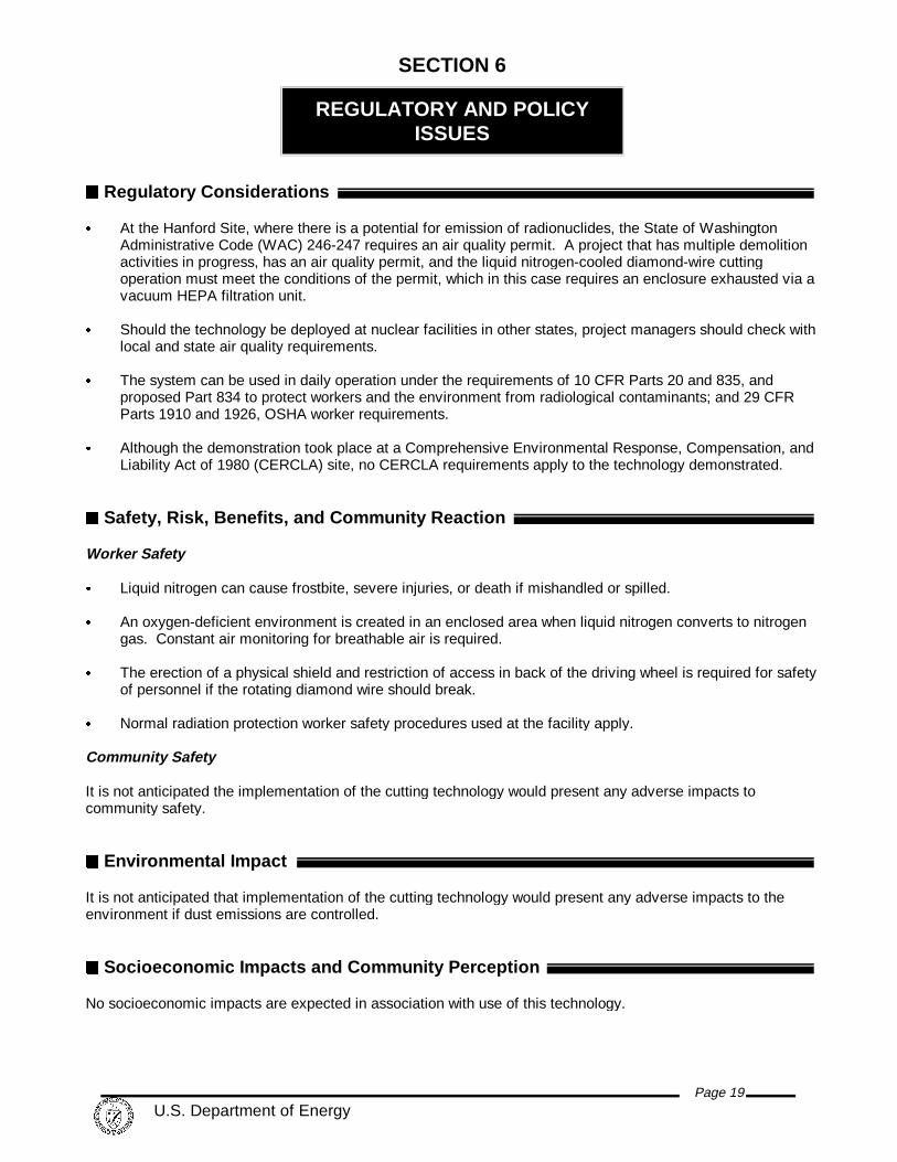
ss Regulatory Considerations
& At the Hanford Site, where there is a potential for emission of radionuclides, the State of WashingtonAdministrative Code (WAC) 246-247 requires an air quality permit. A project that has multiple demolitionactivities in progress, has an air quality permit, and the liquid nitrogen-cooled diamond-wire cuttingoperation must meet the conditions of the permit, which in this case requires an enclosure exhausted via avacuum HEPA filtration unit.
& Should the technology be deployed at nuclear facilities in other states, project managers should check withlocal and state air quality requirements.
& The system can be used in daily operation under the requirements of 10 CFR Parts 20 and 835, andproposed Part 834 to protect workers and the environment from radiological contaminants; and 29 CFRParts 1910 and 1926, OSHA worker requirements.
& Although the demonstration took place at a Comprehensive Environmental Response, Compensation, andLiability Act of 1980 (CERCLA) site, no CERCLA requirements apply to the technology demonstrated.
ss Safety, Risk, Benefits, and Community Reaction
Worker Safety
& Liquid nitrogen can cause frostbite, severe injuries, or death if mishandled or spilled.
& An oxygen-deficient environment is created in an enclosed area when liquid nitrogen converts to nitrogengas. Constant air monitoring for breathable air is required.
& The erection of a physical shield and restriction of access in back of the driving wheel is required for safetyof personnel if the rotating diamond wire should break.
& Normal radiation protection worker safety procedures used at the facility apply.
Community Safety
It is not anticipated the implementation of the cutting technology would present any adverse impacts tocommunity safety.
ss Environmental Impact
It is not anticipated that implementation of the cutting technology would present any adverse impacts to theenvironment if dust emissions are controlled.
ss Socioeconomic Impacts and Community Perception
No socioeconomic impacts are expected in association with use of this technology.

Page 20 U.S. Department of Energy
LESSONS LEARNED
SECTION 7
ss Implementation
No special implementation concerns apply to the liquid nitrogen-cooled diamond-wire technology. A source ofportable Dewar tanks with liquid, low-temperature nitrogen that can make timely deliveries must be identified.
ss Technology Limitations/Needs for Future Development
& As presently designed and operated during the demonstration, the area that can be cut with the improvedtechnology is limited to 2.5 m2 (27 ft2). Overheating and wire damage occurs beyond this point.
& To improve performance, Bluegrass Concrete Cutting, Inc., recommends liquid nitrogen be inserted intothe kerf. Small-scale testing by Bluegrass Concrete Cutting, Inc., indicates increased cooling performanceof the diamond wire and dust reduction with this modification. Bluegrass Concrete Cutting, Inc. alsosuggests that a mixture of liquid nitrogen and water injected into the kerf will provide even greater cuttingperformance while using less water than with traditional diamond-wire cutting.
& An improvedr diamond-wire cooling method might be obtained by having the wire totally submerged inliquid nitrogen as the wire passes through the cooling pipe. However, a cooling pipe housing redesign andexperimentation would be required.
& The insertion of liquid nitrogen, and possibly small amounts of water, in the kerf would be less costly than acooling tube redesign. The performance of a liquid nitrogen and water mixture injected into the kerf shouldbe considered for evaluation.
s Technology Selection Considerations
& The technology is suitable for DOE D&D sites or other sites where concrete structures must be segmented.
& The amounts and types of secondary waste that are acceptable should be the basis for using either liquidnitrogen or water for cooling. Small amounts of liquid slurry from the baseline cutting operation may becollected with less effort than dust waste. Collection of dust waste requires an enclosure of the drivingwheel, wire and pulleys, and coverage of the kerf at the back of the wall. All dust collection techniquesrequire adequate ventilation and dust filtering.
& This new technology should be considered for any concrete cutting situations where contaminated liquidwaste is difficult to handle or is not acceptable.
Page 21 U.S. Department of Energy
REFERENCES
APPENDIX A
10 CFR Part 20, "Standards for Protection Against Radiation,” Code of Federal Regulations, as amended.
10 CFR Part 834, "Environmental Radiation Protection,” Code of Federal Regulations, as proposed.
10 CFR Part 835, "Occupational Radiation Protection,” Code of Federal Regulations, as amended.
29 CFR Part 1910, “Occupational Safety and Health Standards,” Code of Federal Regulations, as amended.
29 CFR Part 1926, “Safety and Health Regulations for Construction,” Code of Federal Regulations, asamended.
USACE, 1996, Hazardous, Toxic, Radioactive Waste Remedial Action Work Breakdown Structure and DataDictionary, U.S. Army Corps of Engineers, Washington, D.C.

Page 22 U.S. Department of Energy
COST COMPARISON
APPENDIX B
ss Introduction
The cost-effectiveness analysis computes the cost for a concrete wall decontamination job by using hourly ratesfor equipment and labor.
The selected basic activities being analyzed come from the Hazardous, Toxic, Radioactive Waste RemedialAction Work Breakdown Structure and Data Dictionary (HTRW RA WBS), USACE, 1996. The HTRW RAWBS, developed by an interagency group, used in this analysis to provide consistency with the establishednational standards.
Some costs are omitted from this analysis so that it is easier to understand and to facilitate comparison withcosts for the individual site. The overhead and general and administrative (G&A) markup costs for the sitecontractor managing the demonstration are omitted from this analysis. Overhead and G&A rates for each DOEsite vary in magnitude and in the way they are applied. Decision makers seeking site-specific costs can applytheir site’s rates to this analysis without having to first back-out the rates used at the Hanford Site.
The following assumptions were used as the basis of the cost analysis:
& Oversight engineering, quality assurance, and administrative costs for the demonstration are not included. These are normally covered by another cost element, generally as an undistributed cost.
& The vendor-provided service rates include procurement costs of 7.5% so that the costs of administering thecontract are accounted for (7.5% x $1,400/day/10 hr/day) plus per diem for two workers (2 workers x$80/day/10/hr/day) = $140/hr labor + $10.50/hr procurement + $16/hr per diem.
& The procurement cost of 7.5% was applied to all purchased equipment costs so that the costs ofadministering the purchase are accounted for (this cost is included in the hourly rate).
& The equipment hourly rates for the Government ownership option are based on general guidance containedin Office of Management and Budget (OMB) circular No. A-94 for Cost Effectiveness Analysis.
& The equipment hourly rates for the site-owned equipment that may be used in support of the improvedequipment (e.g., the site-owned truck that transports the rented improved equipment from the warehousereceiving to the C Reactor) uses standard equipment rates established at Hanford.
& The standard labor rates established by the Hanford Site for estimating D&D work are used in this analysisfor the portions of the work performed by local crafts.
& The analysis uses a 10-hr work day.
& Additionally, an anticipated life of 5 years for the power unit and saw is used. An average usage of 500 hr/year is used in the calculation of hourly rate for the each of the technologies.
MOBILIZATION (WBS 331.01)
Erect Enclosure : An assumption was made that a crew of four D&D workers would take two 9-hour days toconstruct an approximately 18.6-m2 (200-ft2) enclosure. The baseline technologies used water for dust controland did not require an enclosure.
Transport to and from Site : This activity includes transport of personnel and equipment to the C Reactor fromSeattle, Washington and back again (the vendor has several equipment base locations from which to mobilize) isbased on a quote from the vendor.
APPENDIX B continued
Page 23 U.S. Department of Energy
Vendor Matriculation : The vendor personnel obtain badges (2 hours), site orientation (4 hours), and site-specific review of the Safety/Health Plan (0.25 hours) for an assumed total of 8 hours.
Unload/Move Equipment to Work Area: This activity is the observed time for unloading the equipment from thetruck with a forklift and moving it to the work area.
Setup Equipment : This activity involves the preparation required at the work area prior to operation of theequipment and is based on the observed duration.
DECOMMISSIONING (WBS 331.17)
Cut Concrete Wall : During the demonstration, each of the technologies had different cut sizes, approximately27 ft2 for the innovative liquid nitrogen-cooled diamond wire, 36 ft2 for the baseline diamond wire, and 120 ft2 forthe baseline circular saw. The respective production rates were 0.14, 0.20, and 0.08 ft2/min. These productionrates are for actual cutting time and do not include mobilization and other losses associated with non-productionportions of the work (i.e., work breaks and wire splicing/repair). The innovative and baseline diamond-wiredemonstration costs were extrapolated to equal the 120-ft2 circular saw production. Both innovative and baselinediamond-wire technologies consume wire at a cost of $25/ft2 of cut. The innovative technology consumed liquidnitrogen at a rate of 50 L/hr at a cost of $2.35/L (the saw uses 180-L bottles).
Move Saw to Next Cut : This is the observed time to move the diamond-wire water-cooled saw 30 ft to the nextcut. The baseline circular saw did not require movement because all of the necessary track is costed under thesetup.
Replace/S plice Wire : This is the observed time to replace or splice the diamond-wire saws, both nitrogen andwater cooled. Blade replacement for the water-cooled circular saw is included in the operating cost, which is builtinto the hourly equipment rate.
DEMOBILIZATION (WBS 331.21)
Disassemble E quipment : This includes the durations observed for equipment disassembly for each of theinnovative and baseline technologies.
Load Equipment : This activity is the observed time for moving the equipment from the work area and loading itonto a truck with a forklift. It was assumed that loading the water-cooled circular saw and tracks would take 0.5hr.
WASTE DISPOSAL (WBS 331.18)
Disposal of Water and Slurry : This is the time for the disposal of the water and slurry resulting from thebaseline diamond-wire water cooled and circular saw cuts. The estimated time assumes 0.5 hr for loading andunloading and 0.5 hr of total transit time to and from the gravel pit. There was no disposal charge at the gravelpit for water and slurry disposal. Also, the innovative technology only had refuse from the containment tent anddid not incur any incremental disposal costs.
The details of the cost analysis for the innovative and two baseline technologies are summarized in Tables B-1,B-2, and B-3.
AP
PE
ND
IX B
continued
P
age 24 U
.S. D
epartment of E
nergy
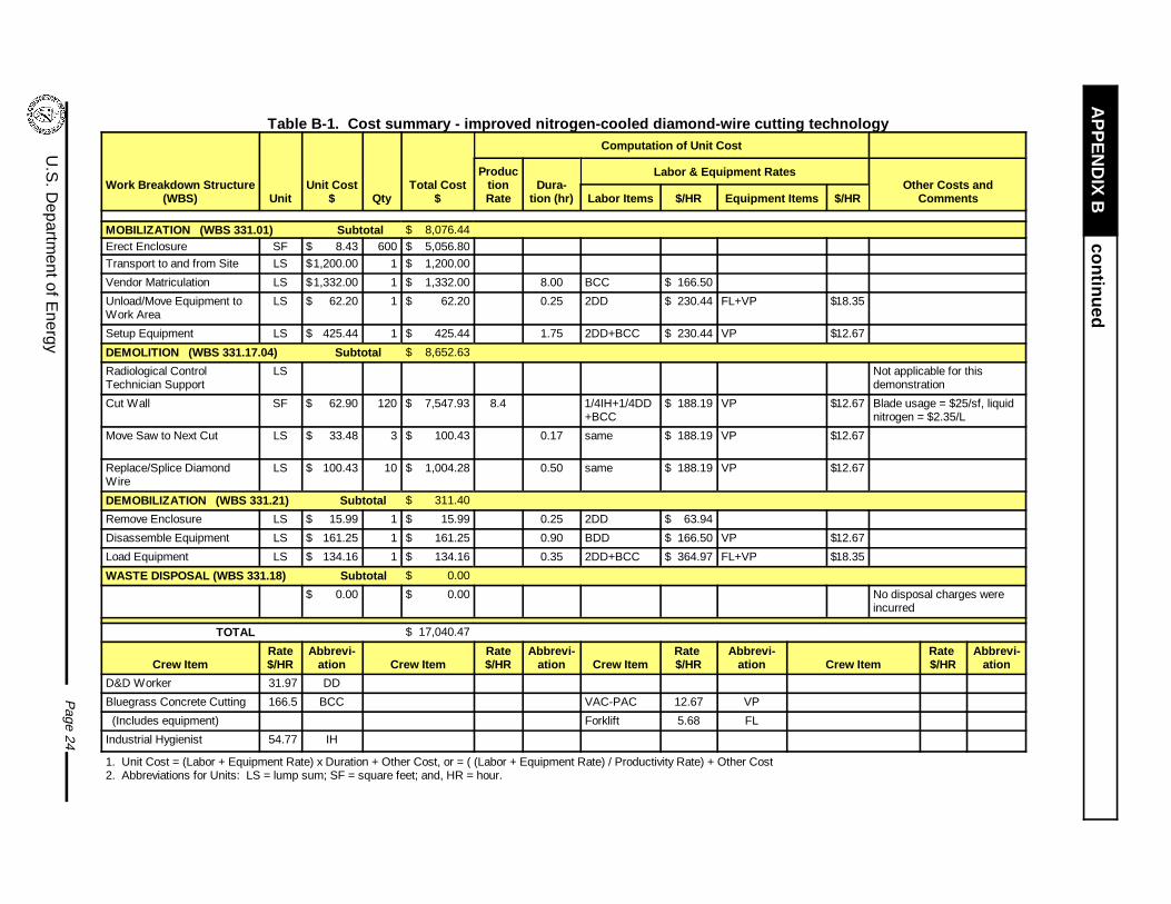
Table B-1. Cost summary - improved nitrogen-c ooled diamond-wire cutting technology
Work Breakdown Structure(WBS) Unit
Unit Cost$ Qty
Total Cost$
Computation of Unit Cost
ProductionRate
Dura-tion (hr)
Labor & Equipment RatesOther Costs and
CommentsLabor Items $/HR Equipment Items $/HR
MOBILIZATION (WBS 331.01) Subtotal $ 8,076.44Erect Enclosure SF $ 8.43 600 $ 5,056.80
Transport to and from Site LS $1,200.00 1 $ 1,200.00
Vendor Matriculation LS $1,332.00 1 $ 1,332.00 8.00 BCC $ 166.50
Unload/Move Equipment toWork Area
LS $ 62.20 1 $ 62.20 0.25 2DD $ 230.44 FL+VP $18.35
Setup Equipment LS $ 425.44 1 $ 425.44 1.75 2DD+BCC $ 230.44 VP $12.67
DEMOLITION (WBS 331.17.04) Subtotal $ 8,652.63
Radiological ControlTechnician Support
LS Not applicable for thisdemonstration
Cut Wall SF $ 62.90 120 $ 7,547.93 8.4 1/4IH+1/4DD+BCC
$ 188.19 VP $12.67 Blade usage = $25/sf, liquidnitrogen = $2.35/L
Move Saw to Next Cut LS $ 33.48 3 $ 100.43 0.17 same $ 188.19 VP $12.67
Replace/Splice DiamondWire
LS $ 100.43 10 $ 1,004.28 0.50 same $ 188.19 VP $12.67
DEMOBILIZATION (WBS 331.21) Subtotal $ 311.40
Remove Enclosure LS $ 15.99 1 $ 15.99 0.25 2DD $ 63.94
Disassemble Equipment LS $ 161.25 1 $ 161.25 0.90 BDD $ 166.50 VP $12.67
Load Equipment LS $ 134.16 1 $ 134.16 0.35 2DD+BCC $ 364.97 FL+VP $18.35
WASTE DISPOSAL (WBS 331.18) Subtotal $ 0.00
$ 0.00 $ 0.00 No disposal charges wereincurred
TOTAL $ 17,040.47
Crew ItemRate$/HR
Abbrevi-ation Crew Item
Rate$/HR
Abbrevi-ation Crew Item
Rate $/HR
Abbrevi-ation Crew Item
Rate $/HR
Abbrevi-ation
D&D Worker 31.97 DD
Bluegrass Concrete Cutting 166.5 BCC VAC-PAC 12.67 VP
(Includes equipment) Forklift 5.68 FL
Industrial Hygienist 54.77 IH
1. Unit Cost = (Labor + Equipment Rate) x Duration + Other Cost, or = ( (Labor + Equipment Rate) / Productivity Rate) + Other Cost2. Abbreviations for Units: LS = lump sum; SF = square feet; and, HR = hour.

AP
PE
ND
IX B
continued
P
age 25 U
.S. D
epartment of E
nergy
Table B-2. Cost Summary - Water-Cooled Diamond-Wire Saw Baseline Technology
Work BreakdownStructure (WBS) Unit
UnitCost $ Qty
TotalCost $
Computation of Unit Cost
Produc-tionRate
Dura-tion (HR)
Labor & Equipment Rates
Other Costs andCommentsLabor Items $/HR
EquipmentItems $/HR
MOBILIZATION (WBS 331.01) Subtotal $ 2,994.30
Transport Vendor to andfrom Site
LS $1,200.00 1 $ 1,200.00
Vendor Matriculation LS $1,332.00 1 $ 1,332.00 8.00 BCC $ 66.50
Unload/Move Equipment toWork Area
LS $ 59.03 1 $ 59.03 0.25 2DD+BCC $230.44 FL $ 5.68
Setup Equipment LS $ 403.27 1 $ 403.27 1.75 2DD+BCC $230.44 $ 0.00
DEMOLITION (WBS 331.17.04) Subtotal $ 5,704.63
Radiological ControlTechnician Support
Not applicable for thisdemonstration
Cut Wall SF $ 39.54 120 $ 4,744.93 12 1/4DD+BCC $ 74.49 $ 0.00 Blade usage = $25/SF
Move Saw to Next Cut LS $ 29.08 3 $ 87.25 0.17 same $ 74.49 $ 0.00
Replace/Splice DiamondWire
LS $ 87.25 10 $ 872.46 0.50 same $ 74.49 $ 0.00
DEMOBILIZATION (WBS 331.21) Subtotal $ 239.69
Disassemble Equipment LS $ 157.04 1 $ 157.04 0.90 BCC $ 74.49 $ 0.00
Load Equipment LS $ 82.64 1 $ 82.64 0.35 2DD+BCC $230.44 FL $ 5.68
WASTE DISPOSAL (WBS 331.18) Subtotal $ 74.36
Disposal of Water & Slurry LS $ 240.86 1 $ 74.36 1.00 2DD $230.44 FL+FB $ 10.42 No disposal charge at gravelpit
TOTAL $ 9,012.98
Crew ItemRate$/HR
Abbrevi-ation Crew Item
Rate$/HR
Abbreviation Crew Item
Rate $/HR
Abbreviation Crew Item
Rate $/HR
Abbreviation
D&D Worker $ 31.97 DD
Bluegrass ConcreteCutting
166.5 BCC
(Includes equipment) Forklift $ 5.68 FL
Industrial Hygienist 54.77 IH Flatbed Truck $ 4.74 FB
1. Unit Cost = (Labor + Equipment Rate) x Duration + Other Cost, or = ( (Labor + Equipment Rate) / Productivity Rate) + Other Cost2. Abbreviations for units: LS = lump sum; SF = square feet; and, HR = hour.

APPENDIX B continued
Page 26 U.S. Department of Energy
Tab
le B
-3.
Cos
t sum
mar
y -
Wat
er-c
oole
d ci
rcul
ar s
aw b
asel
ine
tech
nolo
gy
Wor
k B
reak
dow
nS
truc
ture
(W
BS
)U
nit
Uni
tC
ost $
Qty
Tot
al C
ost
$
Com
puta
tion
of U
nit C
ost
Pro
duc-
tion
Rat
eD
urat
ion
(HR
)
Labo
r &
Equ
ipm
ent R
ates
Oth
er C
osts
and
Com
men
tsLa
bor
Item
s$/
HR
Equ
ipm
ent
Item
s$/
HR
MO
BIL
IZA
TIO
N
(W
BS
331
.01)
Sub
tota
l $
1,59
0.89
Unl
oad/
Mov
e E
quip
men
t to
Wor
k A
rea
LS$
28.1
61
$28
.16
0.25
2DD
$63
.94
CC
S+F
L$
48.6
8
Set
up E
quip
men
tLS
$1,5
62.7
41
$1,
562.
7411
.25
3DD
$95
.91
CC
S$
43.0
0
DE
MO
LIT
ION
(W
BS
331
.17.
04)
Sub
tota
l$
3,47
2.75
Rad
iolo
gica
l Con
trol
Tec
hnic
ian
Sup
port
Not
app
licab
le fo
r th
isde
mon
stra
tion
Cut
Wal
lS
F$
28.9
412
0$
3,47
2.75
4.8
3DD
$95
.91
sam
e$
43.0
0
DE
MO
BIL
IZA
TIO
N
(WB
S 3
31.2
1)
Sub
tota
l$
350.
12
Dis
asse
mbl
e E
quip
men
tLS
$27
7.82
1$
277.
822.
003D
D$
95.9
1sa
me
$43
.00
Load
Equ
ipm
ent
LS$
72.3
01
$72
.30
0.50
3DD
$95
.91
CC
S+F
L$
48.6
8
WA
ST
E D
ISP
OS
AL
(WB
S 3
31.1
8)
Sub
tota
l$
74.3
6
Dis
posa
l of W
ater
& S
lurr
yLS
$74
.36
1$
74.3
61.
002D
D$
63.9
4F
L+F
B$
10.4
2N
o di
spos
al c
harg
e at
gra
vel
pit
TO
TA
L$
5,48
8.12
Cre
w It
emR
ate
$/H
RA
bbre
vi-
atio
nC
rew
Item
Rat
e$/
HR
Abb
revi
-at
ion
Cre
w It
emR
ate
$/H
RA
bbre
vi-
atio
nC
rew
Item
Rat
e $/
HR
Abb
revi
-at
ion
D&
D W
orke
r$
31.9
7D
DW
ater
Coo
led
Circ
ular
Saw
$43.
00C
CS
For
klift
$5.
68F
L
Fla
tbed
Tru
ck$
4.74
FB
1. U
nit C
ost =
(La
bor
+ E
quip
men
t Rat
e) x
Dur
atio
n +
Oth
er C
ost,
or =
( (
Labo
r +
Equ
ipm
ent R
ate)
/ P
rodu
ctiv
ity R
ate)
+ O
ther
Cos
t2.
Abb
revi
atio
ns fo
r un
its:
LS =
lum
p su
m; S
F =
squ
are
feet
; and
, HR
= h
our.
Page 27 U.S. Department of Energy
ACRONYMS AND ABBREVIATIONS
APPENDIX C
Acronym/Abbreviation Description
ALARA as low as reasonably achievable
BHI Bechtel Hanford, Inc.
CERCLA Comprehensive Environmental Response,Compensation, and Liability Act of 1980
D&D decontamination and decommissioning
DOE U.S. Department of Energy
DOE-RL U.S. Department of Energy, Richland OperationsOffice
FETC Federal Energy Technology Center
G&A general and administrative (costs)
HEPA high-efficiency particulate air (filtration)
HTRW hazardous, toxic, radioactive waste
ISS interim safe storage
LSDDP Large Scale Demonstration and Deployment Project
PPE personal protective equipment
RCT
SSE
radiological control technician
safe storage enclosure
USACE U.S. Army Corps of Engineers
WAC Washington Administrative Code
WBS work breakdown structure
Related Documents


