Journal of Power Sources 159 (2006) 626–636 Liquid methanol concentration sensors for direct methanol fuel cells Hengbing Zhao a , Jun Shen a,∗ , Jiujun Zhang a , Haijiang Wang a , David P. Wilkinson a,b , Caikang Elton Gu a a National Research Council of Canada, Institute for Fuel Cell Innovation, 3250 East Mall, Vancouver, BC, Canada V6T 1W5 b Department of Chemical and Biological Engineering, University of British Columbia, 2216 Main Mall, Vancouver, BC, Canada, V6T 1Z4 Received 16 September 2005; accepted 30 September 2005 Available online 18 January 2006 Abstract Liquid-fed direct methanol fuel cells (DMFCs) are one of the most promising candidates for portable power electronics and automotive applications due to their potentially high-energy density, simple storage, and distribution of the fuel. The concentration of methanol in the fuel circulation loop of a DMFC system is an important operating parameter, because it determines the electrical performance and efficiency of the system. The methanol concentration in the circulating fuel stream is usually measured continuously with a suitable sensor for the purpose of maintaining optimal power and efficiency in the DMFC system. Various methods of sensing methanol concentration have been proposed over the past decade. This paper reviews these methanol concentration sensors for DMFCs, which are generally classified into two groups: electrochemical and physical. The construction and operating principles of each sensor, as well as its advantages and disadvantages, are described. The sensorless methods for controlling the methanol concentration are introduced briefly. Finally, the perspective on the future of methanol concentration sensors is discussed. Crown Copyright © 2005 Published by Elsevier B.V. All rights reserved. Keywords: Direct methanol fuel cell; Methanol concentration sensor; Oxidation current; Density; Dielectric constant; Viscosity 1. Introduction New generations of mobile devices offer various advanced features, which require device makers to search for more reli- able and longer lasting power sources beyond what are currently available. Micro and small polymer electrolyte membrane fuel cells (PEMFCs) are one of the most favoured options for new mobile devices. In a PEMFC, hydrogen and methanol are the common fuels. Miniaturization of the hydrogen PEMFC, how- ever, suffers significant limitations with respect to hydrogen storage. Liquid-fed direct methanol fuel cells (DMFCs) have higher energy density and, therefore, are considered to be a more promising candidate for mobile power applications. Methanol is a liquid at room temperature and easy to handle; it has a high-energy density (3800 kcal l −1 ) compared to hydrogen at 360 atm. (658 kcal l −1 ), and it is cheap. Furthermore, the liquid- ∗ Corresponding author. Tel.: +1 604 221 3046; fax: +1 604 221 3001 E-mail address: [email protected] (J. Shen). fed DMFC system does not require a fuel processor and consists of a small number of components, permitting simple, com- pact designs. All of these factors make it a promising power source. The operation of DMFCs is based on the direct oxidation of an aqueous liquid solution of methanol at the anode and con- comitant reduction of oxygen at the cathode: CH 3 OH + H 2 O → CO 2 + 6e − + 6H + (anode) 1.5O 2 + 6e − + 6H + → 3H 2 O (cathode) CH 3 OH + 1.5O 2 → CO 2 + 2H 2 O (overall cell) The methanol concentration in the fuel to be fed to the fuel cell plays a significant role in keeping a predetermined power output from the fuel cell [1]. When the methanol concentra- tion is below a predetermined value, the power output is low and unstable, and when the methanol concentration is above that predetermined value the output power may be obtained, but 0378-7753/$ – see front matter. Crown Copyright © 2005 Published by Elsevier B.V. All rights reserved. doi:10.1016/j.jpowsour.2005.09.067

Welcome message from author
This document is posted to help you gain knowledge. Please leave a comment to let me know what you think about it! Share it to your friends and learn new things together.
Transcript

A
acsmpamiC
K
1
faacmceshpih3
0d
Journal of Power Sources 159 (2006) 626–636
Liquid methanol concentration sensors for direct methanol fuel cells
Hengbing Zhao a, Jun Shen a,∗, Jiujun Zhang a, Haijiang Wang a,David P. Wilkinson a,b, Caikang Elton Gu a
a National Research Council of Canada, Institute for Fuel Cell Innovation,3250 East Mall, Vancouver, BC, Canada V6T 1W5
b Department of Chemical and Biological Engineering, University of British Columbia,2216 Main Mall, Vancouver, BC, Canada, V6T 1Z4
Received 16 September 2005; accepted 30 September 2005Available online 18 January 2006
bstract
Liquid-fed direct methanol fuel cells (DMFCs) are one of the most promising candidates for portable power electronics and automotivepplications due to their potentially high-energy density, simple storage, and distribution of the fuel. The concentration of methanol in the fuelirculation loop of a DMFC system is an important operating parameter, because it determines the electrical performance and efficiency of theystem. The methanol concentration in the circulating fuel stream is usually measured continuously with a suitable sensor for the purpose ofaintaining optimal power and efficiency in the DMFC system. Various methods of sensing methanol concentration have been proposed over the
ast decade. This paper reviews these methanol concentration sensors for DMFCs, which are generally classified into two groups: electrochemical
nd physical. The construction and operating principles of each sensor, as well as its advantages and disadvantages, are described. The sensorlessethods for controlling the methanol concentration are introduced briefly. Finally, the perspective on the future of methanol concentration sensorss discussed.rown Copyright © 2005 Published by Elsevier B.V. All rights reserved.
n curr
fops
ac
C
1
eywords: Direct methanol fuel cell; Methanol concentration sensor; Oxidatio
. Introduction
New generations of mobile devices offer various advancedeatures, which require device makers to search for more reli-ble and longer lasting power sources beyond what are currentlyvailable. Micro and small polymer electrolyte membrane fuelells (PEMFCs) are one of the most favoured options for newobile devices. In a PEMFC, hydrogen and methanol are the
ommon fuels. Miniaturization of the hydrogen PEMFC, how-ver, suffers significant limitations with respect to hydrogentorage. Liquid-fed direct methanol fuel cells (DMFCs) haveigher energy density and, therefore, are considered to be a moreromising candidate for mobile power applications. Methanol
s a liquid at room temperature and easy to handle; it has aigh-energy density (3800 kcal l−1) compared to hydrogen at60 atm. (658 kcal l−1), and it is cheap. Furthermore, the liquid-∗ Corresponding author. Tel.: +1 604 221 3046; fax: +1 604 221 3001E-mail address: [email protected] (J. Shen).
C
Tcotat
378-7753/$ – see front matter. Crown Copyright © 2005 Published by Elsevier B.Voi:10.1016/j.jpowsour.2005.09.067
ent; Density; Dielectric constant; Viscosity
ed DMFC system does not require a fuel processor and consistsf a small number of components, permitting simple, com-act designs. All of these factors make it a promising powerource.
The operation of DMFCs is based on the direct oxidation ofn aqueous liquid solution of methanol at the anode and con-omitant reduction of oxygen at the cathode:
H3OH + H2O → CO2 + 6e− + 6H+ (anode)
.5O2 + 6e− + 6H+ → 3H2O (cathode)
H3OH + 1.5O2 → CO2 + 2H2O (overall cell)
he methanol concentration in the fuel to be fed to the fuelell plays a significant role in keeping a predetermined power
utput from the fuel cell [1]. When the methanol concentra-ion is below a predetermined value, the power output is lownd unstable, and when the methanol concentration is abovehat predetermined value the output power may be obtained, but. All rights reserved.
wer S
ctoeiwt
amtfls
•••
••••
•
tmrgiaimiitttTsaic
2
trmapdt
t(
M
M
M
W
V
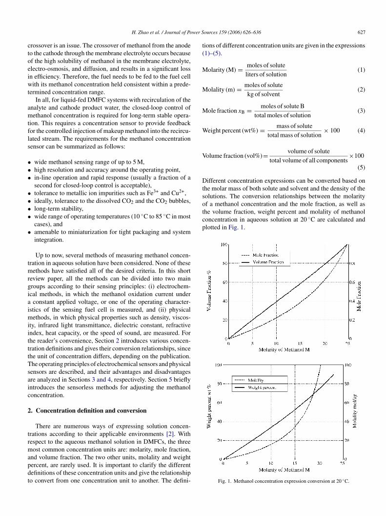
Dtsof a methanol concentration and the mole fraction, as well asthe volume fraction, weight percent and molality of methanolconcentration in aqueous solution at 20 ◦C are calculated andplotted in Fig. 1.
H. Zhao et al. / Journal of Po
rossover is an issue. The crossover of methanol from the anodeo the cathode through the membrane electrolyte occurs becausef the high solubility of methanol in the membrane electrolyte,lectro-osmosis, and diffusion, and results in a significant lossn efficiency. Therefore, the fuel needs to be fed to the fuel cellith its methanol concentration held consistent within a prede-
ermined concentration range.In all, for liquid-fed DMFC systems with recirculation of the
nalyte and cathode product water, the closed-loop control ofethanol concentration is required for long-term stable opera-
ion. This requires a concentration sensor to provide feedbackor the controlled injection of makeup methanol into the recircu-ated stream. The requirements for the methanol concentrationensor can be summarized as follows:
wide methanol sensing range of up to 5 M,high resolution and accuracy around the operating point,in-line operation and rapid response (usually a fraction of asecond for closed-loop control is acceptable),tolerance to metallic ion impurities such as Fe3+ and Cu2+,ideally, tolerance to the dissolved CO2 and the CO2 bubbles,long-term stability,wide range of operating temperatures (10 ◦C to 85 ◦C in mostcases), andamenable to miniaturization for tight packaging and systemintegration.
Up to now, several methods of measuring methanol concen-ration in aqueous solution have been considered. None of these
ethods have satisfied all of the desired criteria. In this shorteview paper, all the methods can be divided into two mainroups according to their sensing principles: (i) electrochem-cal methods, in which the methanol oxidation current under
constant applied voltage, or one of the operating character-stics of the sensing fuel cell is measured, and (ii) physical
ethods, in which physical properties such as density, viscos-ty, infrared light transmittance, dielectric constant, refractivendex, heat capacity, or the speed of sound, are measured. Forhe reader’s convenience, Section 2 introduces various concen-ration definitions and gives their conversion relationships, sincehe unit of concentration differs, depending on the publication.he operating principles of electrochemical sensors and physicalensors are described, and their advantages and disadvantagesre analyzed in Sections 3 and 4, respectively. Section 5 brieflyntroduces the sensorless methods for adjusting the methanoloncentration.
. Concentration definition and conversion
There are numerous ways of expressing solution concen-rations according to their applicable environments [2]. Withespect to the aqueous methanol solution in DMFCs, the threeost common concentration units are: molarity, mole fraction,
nd volume fraction. The two other units, molality and weightercent, are rarely used. It is important to clarify the differentefinitions of these concentration units and give the relationshipo convert from one concentration unit to another. The defini-
ources 159 (2006) 626–636 627
ions of different concentration units are given in the expressions1)–(5).
olarity (M) = moles of solute
liters of solution(1)
olality (m) = moles of solute
kg of solvent(2)
ole fraction xB = moles of solute B
total moles of solution(3)
eight percent (wt%) = mass of solute
total mass of solution× 100 (4)
olume fraction (vol%)= volume of solute
total volume of all components×100
(5)
ifferent concentration expressions can be converted based onhe molar mass of both solute and solvent and the density of theolutions. The conversion relationships between the molarity
Fig. 1. Methanol concentration expression conversion at 20 ◦C.
6 wer Sources 159 (2006) 626–636
3
gdcc
C
F
6
F
1
TtdcctsobmfttcoaPdP
Fo
28 H. Zhao et al. / Journal of Po
. Electrochemical sensing methods
The sensing principle of electrochemical methanol sensors isenerally based on the electro-oxidation of methanol to carbonioxide on platinum/ruthenium (Pt/Ru) anode catalysts and theoncomitant reduction of oxygen or protons on platinum (Pt)athode catalysts.
H3OH + H2O → CO2 + 6e− + 6H+ (anode)
or the oxidation current type sensor:
H+ + 6e− → 3H2 (cathode)
or the fuel cell-based sensor:
.5O2 + 6e− + 6H+ → 3H2O (cathode)
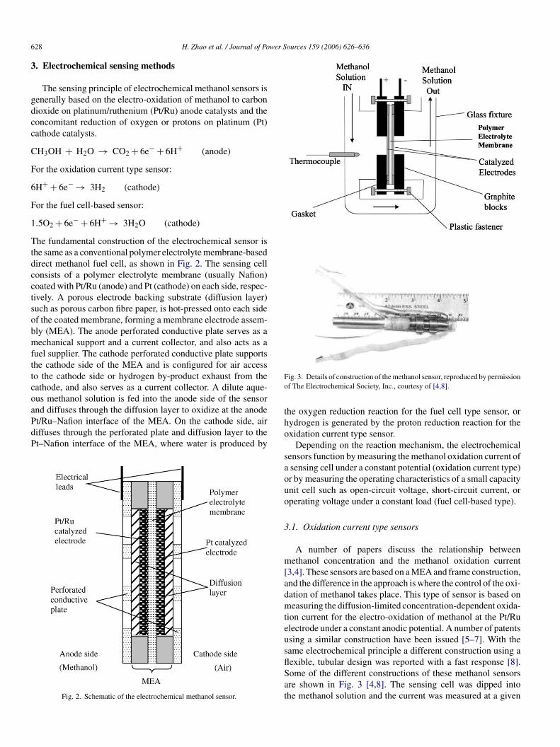
he fundamental construction of the electrochemical sensor ishe same as a conventional polymer electrolyte membrane-basedirect methanol fuel cell, as shown in Fig. 2. The sensing cellonsists of a polymer electrolyte membrane (usually Nafion)oated with Pt/Ru (anode) and Pt (cathode) on each side, respec-ively. A porous electrode backing substrate (diffusion layer)uch as porous carbon fibre paper, is hot-pressed onto each sidef the coated membrane, forming a membrane electrode assem-ly (MEA). The anode perforated conductive plate serves as aechanical support and a current collector, and also acts as a
uel supplier. The cathode perforated conductive plate supportshe cathode side of the MEA and is configured for air accesso the cathode side or hydrogen by-product exhaust from theathode, and also serves as a current collector. A dilute aque-us methanol solution is fed into the anode side of the sensor
nd diffuses through the diffusion layer to oxidize at the anodet/Ru–Nafion interface of the MEA. On the cathode side, airiffuses through the perforated plate and diffusion layer to thet–Nafion interface of the MEA, where water is produced byFig. 2. Schematic of the electrochemical methanol sensor.
tho
saouo
3
m[admteusflSat
ig. 3. Details of construction of the methanol sensor, reproduced by permissionf The Electrochemical Society, Inc., courtesy of [4,8].
he oxygen reduction reaction for the fuel cell type sensor, orydrogen is generated by the proton reduction reaction for thexidation current type sensor.
Depending on the reaction mechanism, the electrochemicalensors function by measuring the methanol oxidation current ofsensing cell under a constant potential (oxidation current type)r by measuring the operating characteristics of a small capacitynit cell such as open-circuit voltage, short-circuit current, orperating voltage under a constant load (fuel cell-based type).
.1. Oxidation current type sensors
A number of papers discuss the relationship betweenethanol concentration and the methanol oxidation current
3,4]. These sensors are based on a MEA and frame construction,nd the difference in the approach is where the control of the oxi-ation of methanol takes place. This type of sensor is based oneasuring the diffusion-limited concentration-dependent oxida-
ion current for the electro-oxidation of methanol at the Pt/Rulectrode under a constant anodic potential. A number of patentssing a similar construction have been issued [5–7]. With theame electrochemical principle a different construction using a
exible, tubular design was reported with a fast response [8].ome of the different constructions of these methanol sensorsre shown in Fig. 3 [4,8]. The sensing cell was dipped intohe methanol solution and the current was measured at a given
H. Zhao et al. / Journal of Power Sources 159 (2006) 626–636 629
FT
cc9[rram
c0tfdrama
3
dmsac
ftiictatcm
Fo
b4mt1sH
atfwoacgen reduction at the cathode. The measured short-circuit currentresponse shows a good linear relationship with the methanolconcentration up to 1 M, as shown in Fig. 6.
ig. 4. Polarization curve for methanol oxidation, reproduced by permission ofhe Electrochemical Society, Inc., courtesy of [4].
ell voltage to determine methanol concentration. Polarizationurves for methanol oxidation at a Pt/Ru–Nafion interface at0 ◦C for various concentrations of methanol are shown in Fig. 44]. The potential applied to the electrodes is generally in theange of 0.45–0.65 V. Higher cell potentials may dissolve theuthenium in the anode catalyst. Cell potentials lower than 0.4 Vre not enough to develop a diffusion-limited current at higherethanol concentrations, i.e., greater than 1 M.This method was alleged to be reliable in the methanol con-
entration range of 0.01–5 M over a wide temperature range of–100 ◦C. This type of methanol sensor is based on measuringhe limited current for methanol oxidation at the anode. There-ore, the sensor only works when the fuel supply is limited byiffusion, and the response of the sensor is relatively slow. Forelatively high methanol concentration, this sensor must be oper-ted at higher current densities. Also, an external power sourceust be applied to the fuel cell to drive the electrode reactions
nd operate the sensor.
.2. Fuel cell-based type sensors
The operating characteristics of the DMFC are greatly depen-ent on the methanol concentration. This fuel cell type ofethanol sensor determines the methanol concentration by mea-
uring the open-circuit voltage, short-circuit current, or the oper-ting voltage of a small capacity liquid DMFC loaded with aonstant resistor.
In the open-circuit state of a DMFC, the methanol crossoverrom the anode side to the cathode side is dependent onhe methanol concentration. As the methanol concentrationncreases on the anode side, the methanol crossover rate alsoncreases. It is well known that the output voltage of the fuelell at open-circuit drops with increasing methanol concentra-ion due to the methanol diffusion through the membrane to the
ir cathode side, as shown in Fig. 5. For a normal DMFC opera-ion, methanol crossover should be reduced to improve the fuelell efficiency. However, the fuel cell type of sensor utilizes theethanol crossover and determines the methanol concentration Fig. 5. Open-circuit voltage of a unit cell vs. methanol concentration, courtesyf [9].
y measuring the reduced open-circuit voltage. In US patent,810,597, the open-circuit voltage of a sensing unit cell waseasured for determining and controlling the methanol concen-
ration in the range of 0.7–1.2 M with a resolution of 0.1 M atM [9]. A similar patent, US patent 2,003,196,913, also con-
idered sensor application based on methanol crossover [10].owever, the reproducibility of these sensors are not very good.In US patent 6,488,837 a methanol electro-oxidation anode
nd an air electro-reduction cathode were shorted togetherhrough an external electrical connection [11]. Methanol accessrom the aqueous solution to the anode catalyst side of the MEAas limited by diffusion through a physical barrier consistingf an aperture opening and a porous medium. In this sensorll the methanol that reaches the anode catalyst is completelyonsumed at the anode (no cross-over) with concomitant oxy-
ig. 6. Short-circuit current vs. methanol concentration, courtesy of [11].
630 H. Zhao et al. / Journal of Power S
rmUdtots[fctmra
estiomr
3
sDtsadoo
[sic
4
tbadwctocba
ciImv
4
wtdt
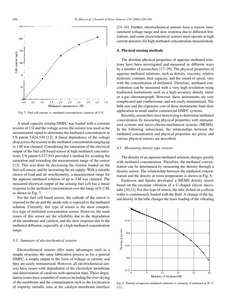
based on the resonant vibration of a U-shaped silicon micro-tube [30,31]. For this type of sensor, the tube etched on a siliconwafer is continuously loaded with the fluid. A change of the liq-uid density in the tube changes the mass loading of the vibrating
Fig. 7. Fuel cell current vs. methanol concentration, courtesy of [13].
A small capacity sensing DMFC was loaded with a constantesistor of 1 � and the voltage across the resistor was used as theeasurement signal to determine the methanol concentration inS patent 5,624,538 [12]. A linear dependency of the voltagerop across the resistor in the methanol concentration ranging upo 1 M was claimed. Considering the saturation of the electricalutput of the fuel cell-based sensor at high methanol concentra-ions, US patent 6,527,943 provided a method for avoiding theaturation and extending the measurement range of the sensor13]. This was done by decreasing the resistor loaded on theuel cell sensor, and by increasing the air supply. With a suitablehoice of load and air stoichiometry, a measurement range forhe aqueous methanol solution of up to 4 M was claimed. The
easured electrical output of the sensing fuel cell has a linearesponse to the methanol concentration over the range of 0–2 M,s shown in Fig. 7.
For the fuel cell-based sensor, the cathode of the sensor isxposed to the air and the anode side is exposed to the methanololution. Currently, this type of sensor is the most competi-ive type of methanol concentration sensor. However, the mainssues of this sensor are the reliability due to the degradationf the membrane and catalyst, and the slow response due to theethanol diffusion, especially at a high methanol concentration
ange.
.3. Summary of electrochemical sensors
Electrochemical sensors offer many advantages such as aimple structure, the same fabrication process as for a generalMFC, a simple output in the form of voltage or current, and
hey are easily miniaturized. However, all electrochemical sen-ors have issues with degradation of the electrolyte membrane
nd deterioration of catalysts with operation time. These degra-ation issues have a number of sources including the over-dryingf the membrane and the contamination such as the localizationf impurity metallic ions at the catalyst–membrane interfaceF[
ources 159 (2006) 626–636
14–16]. Further, electrochemical sensors have a narrow mea-urement voltage range and slow response due to diffusion lim-tations, and some electrochemical sensors must operate at highurrent densities for high methanol concentration measurement.
. Physical sensing methods
The absolute physical properties of aqueous methanol solu-ions have been investigated and measured in different waysy a number of researchers [17–29]. The physical properties ofqueous methanol solutions, such as density, viscosity, relativeielectric constant, heat capacity, and the sound of speed, varyith the concentration of methanol. Therefore, methanol con-
entration can be measured with a very high resolution usingraditional instruments such as a high-accuracy density meterr a gas chromatograph. However, these instruments are veryomplicated and cumbersome, and not easily miniaturized. Theulk size and the expensive cost of these instruments limit theirpplication in small and/or commercial DMFC systems.
Recently, researchers have been trying to determine methanoloncentration by measuring physical properties with miniatur-zed systems and micro-electro-mechanical systems (MEMS).n the following subsections, the relationships between theethanol concentration and physical properties are given, and
arious physical sensors are described.
.1. Measuring density type sensors
The density of an aqueous methanol solution changes greatlyith methanol concentration. Therefore, the methanol concen-
ration can be determined by measuring the density through aensity sensor. The relationship between the methanol concen-ration and the density at room temperature is shown in Fig. 8.
Enoksson and Sparks developed a MEMS density sensor
ig. 8. Density of aqueous methanol solutions vs. molarity of methanol at 20 ◦C21].

H. Zhao et al. / Journal of Power Sources 159 (2006) 626–636 631
Fc
ttVdTteco
mottC
4
b[iF
Fo
F2
tccctse
mmsJcmcma
ig. 9. Cross-sectional illustration of a MEMS density sensor, © 2005 IEEE,ourtesy of [30].
ube and thus shifts the resonant frequency of the vibration dueo the change in the inertial mass of the vibrating tube system.ariations in the density or concentration of the fluid will beetected through a change in the resonant frequency of the tube.here are two holes in the bottom glass chip that admit fluid into
he U-shaped microtube, as shown in Fig. 9. The tube system isxcited electrostatically into resonant vibration and its motionan be detected optically using a laser beam focused on the tube,r capacitively using metal electrodes under the tube.
These density/concentration sensors are very effective atonitoring small fluid volumes and low flow rates and can work
ver the entire concentration range of aqueous methanol solu-ions. However, the sensitivity of these sensors does not satisfyhe requirement of fuel cells, and these sensors are sensitive toO2 bubbles in the fuel loop.
.2. Capacitance type sensors
The dielectric properties of aqueous methanol solutions have
een well investigated by Bao, Mashimo, Sato and Bolund17–20]. The static dielectric constant of these solutions variesn accordance with the methanol concentration, as shown inig. 10. The dielectric constant (or the methanol concentra-ig. 10. Relative dielectric constant of aqueous methanol solutions vs. molarityf methanol in aqueous solution at 23 ◦C [21].
mmcc[
c[bipFcs
tafmvmtd
ig. 11. Measured dielectric spectra of aqueous methanol solution at 20 ◦C, ©005 IEEE, courtesy of [37].
ion) can be determined by measuring the frequency-dependentapacitance. This kind of sensor consists of a capacitor thatomprises a pair of spaced electrode plates or coaxial electrodeylinders submerged in the solution. The solution passes throughhe two electrodes of the formed capacitor and the dielectric con-tant of the solution is detected by measuring the capacitancestablished between the electrodes.
In the early 1980s, this type of sensor was proposed toeasure the methanol concentration in mixed fuels, such as aixture of gasoline and methanol. A plate capacitor methanol
ensor dipped in the fuel tank was disclosed in Japanese patentP56138431 [32], and a coaxial cylinder capacitor was dis-losed in Japanese patent JP4343062 [33]. The capacitanceethanol concentration sensor has the drawbacks of electro-
orrosion of the electrode plates/cylinders, and dissolution ofetallic ions in the fuel due to the application of DC volt-
ge. In order to avoid the above drawbacks and increase theeasurement accuracy of the methanol concentration in theixed fuel, an electrically insulating film was formed on the
ylindrical or plate electrodes of the sensing capacitor as dis-losed in US patents 4,939,467 and 5,196,801, and WO011345134–36].
Doerner et al. measured the dielectric spectra for a methanoloncentration range from 0 wt% to 5 wt%, as shown in Fig. 1137]. When the frequency is above 1 MHz, the dielectric spectraecome flat and stable due to the less influence of contam-nants in the solution. They used a capacitive probe with aair of planar sensing electrodes in a PTFE shell, shown inig. 12, which was used to calculate the complex dielectriconstant and determine the methanol concentration in aqueousolution.
The construction of the capacitance sensor is simple, and dueo the large difference in dielectric constants between methanolnd gasoline, the capacitance sensor works well in this mixeduel. However, the change in dielectric constants of aqueousethanol solution in the low methanol concentration range is
ery small, and therefore it is hard to get a satisfactory measure-ent resolution. Furthermore, this type of methanol concentra-
ion determination is extremely sensitive to metallic ions andissolved CO2 in the fuel loop, which is always present.
632 H. Zhao et al. / Journal of Power Sources 159 (2006) 626–636
F[
4
flvcitsToOmcvt
F2
F[
tlta
wtt
icmtTp
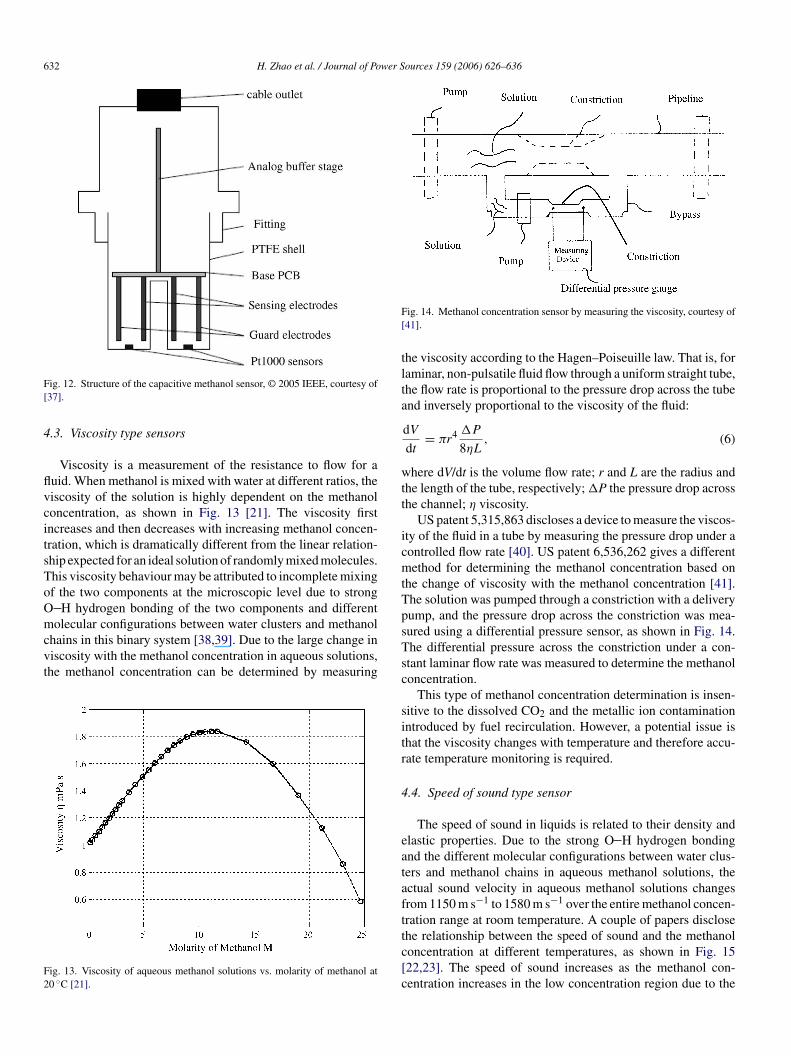
ig. 12. Structure of the capacitive methanol sensor, © 2005 IEEE, courtesy of37].
.3. Viscosity type sensors
Viscosity is a measurement of the resistance to flow for auid. When methanol is mixed with water at different ratios, theiscosity of the solution is highly dependent on the methanoloncentration, as shown in Fig. 13 [21]. The viscosity firstncreases and then decreases with increasing methanol concen-ration, which is dramatically different from the linear relation-hip expected for an ideal solution of randomly mixed molecules.his viscosity behaviour may be attributed to incomplete mixingf the two components at the microscopic level due to strong
H hydrogen bonding of the two components and differentolecular configurations between water clusters and methanol
hains in this binary system [38,39]. Due to the large change iniscosity with the methanol concentration in aqueous solutions,he methanol concentration can be determined by measuring
ig. 13. Viscosity of aqueous methanol solutions vs. molarity of methanol at0 ◦C [21].
sTsc
sitr
4
eatafttc[c
ig. 14. Methanol concentration sensor by measuring the viscosity, courtesy of41].
he viscosity according to the Hagen–Poiseuille law. That is, foraminar, non-pulsatile fluid flow through a uniform straight tube,he flow rate is proportional to the pressure drop across the tubend inversely proportional to the viscosity of the fluid:
dV
dt= πr4 �P
8ηL, (6)
here dV/dt is the volume flow rate; r and L are the radius andhe length of the tube, respectively; �P the pressure drop acrosshe channel; η viscosity.
US patent 5,315,863 discloses a device to measure the viscos-ty of the fluid in a tube by measuring the pressure drop under aontrolled flow rate [40]. US patent 6,536,262 gives a differentethod for determining the methanol concentration based on
he change of viscosity with the methanol concentration [41].he solution was pumped through a constriction with a deliveryump, and the pressure drop across the constriction was mea-ured using a differential pressure sensor, as shown in Fig. 14.he differential pressure across the constriction under a con-tant laminar flow rate was measured to determine the methanoloncentration.
This type of methanol concentration determination is insen-itive to the dissolved CO2 and the metallic ion contaminationntroduced by fuel recirculation. However, a potential issue ishat the viscosity changes with temperature and therefore accu-ate temperature monitoring is required.
.4. Speed of sound type sensor
The speed of sound in liquids is related to their density andlastic properties. Due to the strong O H hydrogen bondingnd the different molecular configurations between water clus-ers and methanol chains in aqueous methanol solutions, thectual sound velocity in aqueous methanol solutions changesrom 1150 m s−1 to 1580 m s−1 over the entire methanol concen-ration range at room temperature. A couple of papers disclose
he relationship between the speed of sound and the methanoloncentration at different temperatures, as shown in Fig. 1522,23]. The speed of sound increases as the methanol con-entration increases in the low concentration region due to the
H. Zhao et al. / Journal of Power Sources 159 (2006) 626–636 633
Fc
slfcwatob
soi0wwtaoo
�
watom
ittrtmtr
F
4
wtqsar
cocrelated to small changes in the methanol concentration, asshown in Fig. 17. This can be used to analyze the methanolconcentration. The transmittance of IR radiation was detectedby an infrared sensor and used for analysis of the methanol
ig. 15. The speed of sound in aqueous methanol solutions vs. methanol con-entration in weight percent [22].
trong water–water hydrogen bonds and the increasing chainength of the methanol. As the concentration of methanol isurther increased, the speed of sound in the high methanol con-entration region decreases due to the replacement of the strongater–water hydrogen bonds with the weaker water–methanol
nd methanol–methanol hydrogen bonds. Also, as the tempera-ure increases, the maximum sound speed shifts to a lower valuef the methanol concentration due to changes in the hydrogenond length.
US patent 6,748,793 [42] discloses a method for ultrasoundensing of the methanol concentration in aqueous solution basedn observed sound velocity. Changes of methanol concentrationn the range of 0.1–5% by weight, and a resolution of up to.1% were reported. In this patent a piezoelectric transduceras used, working as a transmitter to emit ultrasound waves, asell as a receiver to detect the reflected ultrasound waves from
he opposite side, as shown in Fig. 16. Using similar referencend sample chambers, the differential propagation time �t(xm)f the ultrasound pulses was measured in response to the changef methanol concentration.
t(xm) = L
v(xm)− L
vr(7)
here L is the propagation length of the ultrasound pulses; vrnd v(xm) are the speed of sound in the reference chamber andhe sample chamber, respectively. For a propagation length Lf 0.5 M, a time difference �t of 0.111 �s corresponded to aethanol concentration change of 0.1 wt%.This method of methanol concentration determination is
nsensitive to the dissolved CO2 and the metallic ion contamina-ion introduced by fuel recirculation. However, CO2 bubbles inhe fuel will affect the propagation of the ultrasound wave. Theesolution of such a sensing system depends on the length of
he propagation path. This device is complicated and not easilyiniaturized, and the measurement method is intermittent. Fur-hermore, a higher temperature will decrease the measurementesolution.
Fo
ig. 16. Methanol sensor based on the speed of sound, courtesy of [42].
.5. Infrared spectrum type sensor
Usually, photon energies in the infrared region, ranging inavelength from 2.5 �m to 16 �m, can induce vibrational exci-
ation of covalently bonded atoms and groups. The exact fre-uency at which a given vibration occurs is determined by thetrength of the bonds involved and the mass of the componenttoms. Infrared absorption spectra of compounds are uniqueeflections of their molecular structure and configuration.
For low concentrations of aqueous methanol solutions, thehange of the absorption frequency or wavenumber is notbservable in the specific band of the IR spectrum. However,hanges in the amplitude of absorption can be observed and
ig. 17. Peak absorption of IR spectra for aqueous methanol solutions, courtesyf [43].

634 H. Zhao et al. / Journal of Power Sources 159 (2006) 626–636
c6to
mstt
4
iiftcu
dcpccrcfiotsapa
ia
z
Apbo
e
Cdmi
λ
wia
itctmer
tct
4
cri
Fig. 18. Refractive index vs. methanol concentration [21].
oncentration in aqueous methanol solutions in US patent,815,682 [43]. The patent reported effective measurement ofhe methanol concentration in the range of 0–5 wt% with a res-lution of 0.1 wt%.
This method has a high measurement resolution at lowethanol concentrations of less than 1 M. However, the dis-
olved CO2 and CO2 bubbles will shift the frequency at whichhe peak absorption occurs, affecting the measurement resolu-ion.
.6. Refractive index type sensor
The ratio of light speed in a vacuum to its speed in the mediums the refractive index. Light travels slower in any medium thann a vacuum. When light travels at an angle between two dif-erent materials, their refractive indices determine the angle ofransmission (or refraction) of the light beam. Fig. 18 shows thehange of the refractive index in an aqueous methanol solutionp to a methanol concentration of 25 M [21].
During the past decade, a variety of techniques have beeneveloped to measure the refractive index for determining theoncentration of a binary solution. Longtin and Fan [44] pro-osed a HeNe laser system-based technique to determine theoncentration of a methanol aqueous solution with a high pre-ision on the order of 0.01 wt% over the entire concentrationange. Japanese patent JP3251745 discloses a methanol con-entration sensor based on the transmission of light through abre in the mixed fuel, as shown in Fig. 19 [45]. A U-shapedptical fibre is immersed in the fuel channel and has direct con-act with the mixed fuel of methanol and gasoline. A transmitteruch as a LED, is applied at one end of the fibre to generate lightccording to the applied electrical signal. A receiver such as ahotocoupler is positioned at the other end of the fibre to receivend convert the transmitted light back to the electrical signal.
For a general LED, the relationship between luminous flux
ntensity z and input voltage ei can be approximately expresseds:= αiei + βi (8)
urtw
Fig. 19. Optical methanol concentration sensor, courtesy of [45].
ssume that all the transmitted light λ(n)z is received by thehotocoupler and the transition loss of light (1−λ)z is introducedy refraction at the fibre/solution interface. The output voltagef the receiver can be expressed as:
o = αoλ(n)z + βo (9)
hanging the applied voltage on the LED from ei1 to ei2 andetecting the output of the photocoupler eo1 and eo2, the trans-ittance of the fibre λ(n), which is the function of the refractive
ndex n, can be calculated from:
(n) = eo1 − eo2
αoαi(ei2 − ei1)(10)
here n is the refractive index at the fibre/solution interface; λ
s the transmittance of light through the fibre; αi, βi and αo, βore the constants related to the LED and the photocoupler.
The optical transmission characteristics of the fibre immersedn an aqueous methanol solution are very much dependent uponhe refractive indices of the fibre and the solution, and espe-ially on the variation in the solution’s index of refraction. Theransmittance of light through the fibre, which depends on the
ethanol concentration, can be calculated based on the appliedlectrical signal to the transmitter and the electrical output of theeceiver.
This methanol concentration sensor is robust. However, dueo the small variation of the refractive index with the methanoloncentration in an aqueous solution, the measurement resolu-ion is low.
.7. Heat capacity type sensor
Heat capacity is the ability of matter to store heat. The heatapacity of a given amount of matter is the quantity of heatequired to raise its temperature by 1 K. Molar heat capacitys usually used in chemistry and defined as heat capacity per
nit mole of a substance, that is, the amount of heat energyequired to raise the temperature of 6.022 × 10²³ molecules ofhe substance by 1 K. The molar isobaric heat capacities of pureater and methanol at 15 ◦C are 75.4 JK−1 mol−1 (C∗p1) and

H. Zhao et al. / Journal of Power S
Fm
7srS(th
C
wC
itr
mC
tivcdod
stsAprrccwt
ith
4
cmrcrrsctss
5
aapcittrccrrbotcctfa
sdmtf
6
method sensors despite issues with degradation of the electrolyte
ig. 20. Molar excess isobaric heat capacity of aqueous methanol solutions vs.ole fraction of methanol [24,25].
8.7 JK−1 mol−1 (C∗p2
), respectively. For an aqueous methanololution the molar heat capacity has an unexpected changeelated to the methanol concentration. Benson et al. [24,25] andimonosn et al. [46] obtained the molar isobaric heat capacitiesCp,m) of aqueous methanol solutions at different temperatureshrough experiments and calculated the molar excess isobariceat capacities (CE
p,m) from the relation:
Ep,m = Cp,m − (1 − x)C∗
p1− xC∗
p2(11)
here x is the mole fraction of methanol in the aqueous solution;Ep,m the molar excess isobaric heat capacity; Cp,m the molar
sobaric heat capacity from the experiment; and C∗p1
, C∗p2
arehe molar isobaric heat capacities of pure water and methanol,espectively.
The molar excess isobaric heat capacities of aqueousethanol solutions obtained by Benson are plotted in Fig. 20.Ep,m is positive and increases with temperature at all mole frac-
ions due to an increasing net disruption of hydrogen bonds withncreasing temperature. The maximum of CE
p,m shifts to higheralues of x with increasing temperature. The molar excess heatapacity rises steeply in the range from x = 0 to x = 0.2 beforeecreasing. The increasing chain length of the methanol in aque-us solution is believed to be responsible for the unexpectedecrease of the molar heat capacity.
US patent 20,020,148,284 [47] provides a method for mea-uring the methanol concentration in aqueous solution, usinghe fact that the specific heat capacity of an aqueous methanololution is greatly dependent on the methanol concentration.
known quantity of heat, Q, was supplied to the solution, byumping it through a heating cell at a constant flow rate, and theesulting increase in temperature or temperature difference wasecorded. The temperature difference is proportional to the spe-ific heat capacity which changes as a function of the methanol
oncentration. A temperature difference of approximately 2 ◦Cas reported for a change of methanol concentration from 0.5 Mo 1 M with a flow rate of 100 ml min−1.
mTp
ources 159 (2006) 626–636 635
This method is insensitive to the pH and metallic ion contam-nation of the methanol solution. However, a pump is necessaryo maintain a constant flow rate in the solution and a constanteating power source is required.
.8. Summary of physical sensors
Physical methanol concentration sensors measure thehanges in physical properties of the solution and then deter-ine the methanol concentration of the solution based on the
elationship between the physical properties and the methanoloncentration. Most of these sensors are relatively reliable andobust. However, auxiliary driving devices and other sensors areequired, such as a pump for a constant flow rate and a pressureensor for measuring the pressure drop, make the sensing systemomplex. The complexity of physical sensors makes it difficulto miniaturize this type of sensor. Furthermore, physical sen-ors are temperature-dependent and may require a temperatureensor as well for temperature compensation.
. Other measurement methods
Compared to the conventional methods of employingmethanol concentration sensor, a couple of sensorless
pproaches have been disclosed to decrease the cost and com-lexity of the fuel cell system and improve the stability of fuelell operation by monitoring one or more of the fuel cell’s operat-ng characteristics. The sensorless method increases or decreaseshe concentration of methanol supplied to the anode according tohe preferred choice of an operating characteristic and a knownelationship between the characteristic and the methanol con-entration. In US patent 6,589,679 [48], a change of methanoloncentration is introduced by periodically reducing or inter-upting the amount of methanol supplied to fuel cell and theate of the potential drop can be used; or the potential differenceetween the inlet and outlet of the methanol flow can be used;r the load is periodically disconnected from the fuel cell andhe open-circuit potential can be used to adjust the methanoloncentration. US patent 6,698,278 [49] calculates methanoloncentration in the fuel stream based on the measurement ofhe temperature of the fuel stream entering the fuel cell stack, theuel cell stack temperature indicating the operating temperature,nd the load current.
The sensorless methods do simplify the design of the fuel cellystem. However, the sensorless methods are based on the pre-etermined calibration of the fuel cell system and on empiricalodels. The monitoring and control of the methanol concentra-
ion are inexact due to the complexity of fuel cell operation anduel cell degradation.
. Conclusions
Electrochemical sensors offer many advantages over physical
embrane and catalyst performance over long-term operation.hey are still used extensively in small fuel cells due to their sim-le structure, which is compatible with the fabrication process of
6 wer S
Diceirsmbwad
rptfrts
fptstpodh
R
[[[
[
[[[
[
[[
[
[
[[
[
[[
[
[[[
[
[[
[[[[
[
[
[[[[
[
[
36 H. Zhao et al. / Journal of Po
MFCs, and their simple output in the form of electrical signals,.e., voltage or current. With the improvement of membrane andatalyst degradation and the development of new materials, thelectrochemical sensor will prevail for a long time. However,t is difficult to overcome the narrow sensing range and slowesponse due to the diffusion limitation with electrochemicalensors. This diffusion limitation is more pronounced at higherethanol concentrations. With the development of new mem-
ranes for DMFCs working at higher methanol concentrationith reduced crossover, this electrochemical sensor will face
n increasing challenge from the physical sensor which is notiffusion limited.
Physical methanol concentration sensors are reliable andobust, and have a wide measurement range, but they are com-lex and not easily miniaturized. With the application of MEMSechnology, physical sensors will be more attractive for smalluel cells. The development of higher power density DMFCsunning at higher methanol concentration will help to acceleratehe application of physical methanol concentration sensors inmall DMFCs.
It is well known that the molecular interactions present in dif-erent binary liquid mixtures contributes to many of the physicalroperties of liquid system such as density, viscosity, dielec-ric constant, refractive index. Due to the similar moleculartructure and intermolecular interactions, other aqueous solu-ions of alcohols such as ethanol and propanol have similarhysical properties varying with alcohol concentrations as aque-us methanol solution. Therefore, most of physical sensors foretecting the methanol concentration can be used for other alco-ols.
eferences
[1] T. Schultz, S. Zhou, K. Sundmacher, Chem. Eng. & Tech. 24 (2001)1223–1233.
[2] D.R. Lide (Ed.), Handbook of Chemistry and Physics—Section 2, 85th ed.,CRC Press, 2004, pp. 38–59.
[3] S.A.C. Barton, B.L. Murach, T.F. Fuller, A.C. West, J. Electrochem. Soc.145 (1998) 3783–3788.
[4] S.R. Narayanan, T.I. Valdez, W. Chun, Electrochem. Solid-State Lett. 3(2000) 117–120.
[5] T. Tsukui, S. Yasukawa, T. Shimizu, R. Doi, M. Yamaguchi, S. Iwaasa, USpatent 4,629,664 (1986).
[6] S. Surampudi, H.A. Frank, S.R. Narayanan, W. Chun, B. Jeffries-Nakamura, A. Kindler, G. Halpert, US patent 5,773,162 (1998).
[7] S.R. Narayanan, W. Chun, T.I. Valdez, US patent 6,306,285 (2001).[8] Z. Qi, C. He, M. Hollett, A. Attia, A. Kaufman, Electrochem. Solid-State
Lett. 6 (2003) A88–A90.
[9] T. Kumagai, T. Horiba, T. Kamo, S. Takeuchi, K. Iwamoto, K. Kitami, K.Tamura, US patent 4,810,597 (1989).10] T. Xie, D. Chartouni, C. Ohler, US patent 2003196913 (2003).11] X. Ren, S. Gottesfeld, US patent 6,488,837 (2002).12] G. Luft, G. Starbeck, US patent 5,624,538 (1997).
[
[[[
ources 159 (2006) 626–636
13] J. Zhang, K.M. Colbow, D.P. Wilkinson, J. Mueller, US patent 6,527,943(2003).
14] T. Okada, J. Electroanal. Chem. 465 (1999) 1–17.15] T. Okada, J. Electroanal. Chem. 465 (1999) 18–29.16] T. Okada, N. Nakamura, M. Yuasa, I. Sekine, J. Electrochem. Soc. 144
(1997) 2744–2750.17] J.Z. Bao, M.L. Swicord, C.C. Davis, J. Chem. Phys. 104 (1996) 4441–
4450.18] T. Sato, A. Chiba, R. Nozaki, J. Mol. Liquids 101 (2002) 99–111.19] B.F. Bolund, M. Berglund, H. Bernhoff, J. Appl. Phys. 93 (2003)
2895–2899.20] S. Mashimo, S. Kuwabara, S. Yagihara, K. Higasi, J. Chem. Phys. 90 (1989)
3292–3294.21] D.R. Lide (Ed.), Handbook of Chemistry and Physics—Section 8, 85th ed.,
CRC Press, 2004, p. 70.22] A. Ozawa, A. Minamisawa, Jpn. J. Appl. Phys. 37 (1998) 2799–2800.23] C.M. Sehgal, B.R. Porter, J.F. Greenleaf, J. Acous. Soc. Am. 79 (1986)
566–570.24] G.C. Benson, P.J. D’Arcy, O. Kiyohara, J. Solution Chem. 9 (1980)
931–938.25] G.C. Benson, P.J. D’Arcy, J. Chem. Eng. Data 27 (1982) 439–442.26] D.R. Lide (Ed.), Handbook of Chemistry and Physics—Section 6, 85th ed.,
CRC Press, 2004, p. 154.27] A. Rodriguez, J. Canosa, J. Tojo, J. Chem. Thermodyn. 33 (2001)
1383–1397.28] H. Yilmaz, Turkish J. Phys. 26 (2002) 243–246.29] M. Kosmulski, J. Coll. Interf. Sci. 156 (1993) 305–310.30] D. Sparks, R. Smith, M. Straayer, J. Cripe, R. Schneider, S. Massoud-
Ansari, N. Najafi, in: The 12th International Conference on Solid Sensors,Actuators and Microsystems—Transducers ’03, Boston, USA, June 8–12,2003, pp. 300–303.
31] P. Enoksson, G. Stemme, E. Stemme, Sens. Actuators A: Phys. 47 (1995)327–331.
32] T. Maeda et al., Japanese patent JP56138431 (1981).33] H. Kamioka, M. Shimamur, K. Kobayashi, Japanese patent JP4343062
(1992).34] Y. Nogami, H. Nunokawa, US patent 4,939,467 (1990).35] Y. Nogami, H. Nunokawa, T. Hirota, US patent 5,196,801 (1993).36] M. Frank, WIPO patent WO0113451 (2001).37] S. Doerner, T. Schultz, T. Schneider, K. Sundmacher, P. Hauptmann, Pro-
ceedings of the IEEE Sensors 2004. Vienna, Austria, vol. 2, pp. 639–641.
38] J.H. Guo, Y. Luo, A. Augustsson, S. Kashtanov, J.E. Rubensson, D.K. Shuh,H. Agren, J. Nordgren, Phys. Rev. Lett. 91 (2003) 157401–157404.
39] S. Dixit, J. Crain, W.C.K. Poon, J.L. Finney, A.K. Soper, Nature 416 (2002)829–832.
40] N.T. Cowper, US patent 5,315,863 (1994).41] M. Baldauf, W. Preidel, US patent 6,536,262 (2003).42] A. Rabinovich, D. Tulimieri, US patent 6,748,793 (2004).43] A. Rabinovich, E. Diatzikis, J. Mullen, D. Tulimieri, US patent 6,815,682
(2003).44] J.P. Longtin, C.H. Fan, Microscale Thermophys. Eng. 2 (1998) 261–
272.45] H. Kodama, S. Kitajima, T. Suga, Japanese patent JP3251745 (1991).
46] J.M. Simonson, D.J. Bradley, R.H. Busey, J. Chem. Thermodyn. 19 (1987)479–492.47] M. Baldauf, W. Lager, W. Preidel, US patent 2002148284 (2002).48] W.P. Acker, M.S. Adler, US patent 6,589,679 (2003).49] J. Zhang, K.M. Colbow, A. Wong, B. Lin, US patent 6,698,278 (2004).
Related Documents