EXPERIMENT MODULE CHEMICAL ENGINEERING EDUCATION LABORATORY LIQUID-GAS CONTACTOR (KGC) CHEMICAL ENGINEERING FACULTY OF INDUSTRIAL TECHNOLOGY INSTITUT TEKNOLOGI BANDUNG 2018

Welcome message from author
This document is posted to help you gain knowledge. Please leave a comment to let me know what you think about it! Share it to your friends and learn new things together.
Transcript

EXPERIMENT MODULE
CHEMICAL ENGINEERING EDUCATION LABORATORY
LIQUID-GAS CONTACTOR
(KGC)
CHEMICAL ENGINEERING
FACULTY OF INDUSTRIAL TECHNOLOGY
INSTITUT TEKNOLOGI BANDUNG
2018

INSTRUCTIONAL LABORATORY
CHEMICAL ENGINEERING FTI - ITB
MODUL KONTAKTOR GAS CAIR (KGC)
KGC – 2018 2
Contributors:
Dr. Mubiar Purwasasmita, Dr. Retno Gumilang Dewi, Dr. Ardiyan Harimawan, Kevin
Yonathan, Rosa Citra Aprilia, Darien Theodric

INSTRUCTIONAL LABORATORY
CHEMICAL ENGINEERING FTI - ITB
MODUL KONTAKTOR GAS CAIR (KGC)
KGC – 2018 3
TABLE OF CONTENTS
TABLE OF CONTENTS ............................................................................................................................... 3
LIST OF FIGURES ...................................................................................................................................... 5
LIST OF TABLES ........................................................................................................................................ 6
CHAPTER I................................................................................................................................................ 7
PREFACE .................................................................................................................................................. 7
CHAPTER II .............................................................................................................................................. 8
EXPERIMENT OBJECTIVES AND GOALS ................................................................................................... 8
2.1 Goals ............................................................................................................................................. 8
2.2 Objectives...................................................................................................................................... 8
CHAPTER III ............................................................................................................................................. 9
EXPERIMENTAL DESIGN .......................................................................................................................... 9
3.1 Equipment Layout ......................................................................................................................... 9
3.2 Supporting Equipment ................................................................................................................ 10
3.3 Material/Chemical Substances ................................................................................................... 10
CHAPTER IV ........................................................................................................................................... 11
WORKING PROCEDURE ......................................................................................................................... 11
4.1 Calibration of Flow and Measurement of Monophase Pressure Difference .............................. 11
4.2 Measurement of pressure difference, Hold-Up Volume, and Multiphase Flow Regime ........... 13
BIBLIOGRAPHY ...................................................................................................................................... 14
APPENDIX .............................................................................................................................................. 15
A. Raw Data Table ......................................................................................................................... 15
A.1 Experiment on Counter Current Column ............................................................................... 15
A.2 Experiment on Co-current Column ......................................................................................... 17
B. Calculation Procedure ............................................................................................................... 19
B.1 Calibration of Gas Flowrate .................................................................................................... 19
B.3 Determining Gas Mass Flux .................................................................................................... 21
B.4 Determining Liquid Mass Flux ................................................................................................. 21
B.5 Determining Pressure Difference ........................................................................................... 22
B.6 Determining % Liquid Hold-Up ............................................................................................... 22
B.7 Calculation with Burke-Plummer Equation............................................................................. 24
B.8 Calculation with Blake-Kozeny Equation ................................................................................ 24
B.9 Calculation with Ergun Equation ............................................................................................. 24

INSTRUCTIONAL LABORATORY
CHEMICAL ENGINEERING FTI - ITB
MODUL KONTAKTOR GAS CAIR (KGC)
KGC – 2018 4
C. Specification and Literature Data ................................................................................................ 25
C.1 Physical Properties of Water ............................................................................................. 25
C.2 Other constant value ........................................................................................................ 25
JOB SAFETY ANALYSIS ........................................................................................................................... 26
INSTRUCTIONAL LABORATORY
CHEMICAL ENGINEERING FTI - ITB
MODUL KONTAKTOR GAS CAIR (KGC)
KGC – 2018 5
LIST OF FIGURES
Figure 1. Phase deformation of flow in liquid-gas contactor. ................................................................. 7
Figure 2. Equipment layout. .................................................................................................................... 9
Figure 3. Procedure for flow calibration and measurement of monophase gas pressure difference. .... 11
Figure 4. Procedure of flow calibration and measurement of monophase liquid pressure difference. . 12
Figure 5. Procedure for multiphase flow experiment............................................................................ 13
INSTRUCTIONAL LABORATORY
CHEMICAL ENGINEERING FTI - ITB
MODUL KONTAKTOR GAS CAIR (KGC)
KGC – 2018 6
LIST OF TABLES
Table 1. Data for determining gas flowrate in counter current column. ............................................... 15
Table 2. Data for determining gas flowrate in counter column column. .............................................. 15
Table 3. Data for liquid-gas hydrodinamics experiment in counter current column. ........................... 16
Table 4. Data for determining gas flowrate in co-current column. ....................................................... 17
Table 5. Data for determining liquid flowrate in co-current column. ................................................... 17
Table 6. Data for liquid-gas hydrodinamics experiment in co-current column. ................................... 18

INSTRUCTIONAL LABORATORY
CHEMICAL ENGINEERING FTI - ITB
MODUL KONTAKTOR GAS CAIR (KGC)
KGC – 2018 7
CHAPTER I
PREFACE
The two-phase gas-liquid reactor is an example of the simplest polyphase reactor. It is called
polyphase because the reactor contacts two distinct phases including the insoluble phases. In
general, chemical process in operations take place in many phases at the same time. The two
phase liquid-gas reactor is often called a bubble reactor that can be cocurrent or counter
current. The difference between two phase flows in this reactor with the dispersion flow of
solids such as sedimentation, ion exchange, and so forth is the possibility of change in the
size of the gas bubbles along the stream. The liquid-gas contactor module will discuss about
hydrodinamic properties of two phase flow.
The novelty in a multiphase reactor that never occurs in a homogeneous reactor is the
distribution of phase spaces consisting of bubbles, droplets, films, ridges, and so on. This
distribution occurs due to the forces involved, the morphology of the column, volumetric
flowrate of each phase, and the nature of each fluid. Various types of flow that can occur in
the cocurrent liquid gas flow to the top in a column are shown in Figure 1.
Figure 1. Phase deformation of flow in liquid-gas contactor.

INSTRUCTIONAL LABORATORY
CHEMICAL ENGINEERING FTI - ITB
MODUL KONTAKTOR GAS CAIR (KGC)
KGC – 2018 8
CHAPTER II
EXPERIMENT OBJECTIVES AND GOALS
2.1 Goals
The purpose of this practicum is to understand the characteristics of gas-liquid contactor
systems especially the hydrodynamics of the two phase system.
2.2 Objectives
The objectives achieved at the end of the practicum are that students can observe the flow
regime, measure the liquid hold-up, pressure difference for different variations of gas/liquid
flow rate. Compare the above characteristics for the three main equipments.

INSTRUCTIONAL LABORATORY
CHEMICAL ENGINEERING FTI - ITB
MODUL KONTAKTOR GAS CAIR (KGC)
KGC – 2018 9
CHAPTER III
EXPERIMENTAL DESIGN
3.1 Equipment Layout
Figure 2. Equipment layout.
Keterangan:
1. Packed Column (Co-current dan counter current)
2. Wet test meter
3. Water tank
4. Water rotameter
5. Gas rotameter
6. Manometer
7. Measuring cup
L = water flow; G = gas flow; z = column height; D = column diameter

INSTRUCTIONAL LABORATORY
CHEMICAL ENGINEERING FTI - ITB
MODUL KONTAKTOR GAS CAIR (KGC)
KGC – 2018 10
3.2 Supporting Equipment
1. Stopwatch
2. Wet test meter
3. Screwdriver
3.3 Material/Chemical Substances
1. Air
2. Water

INSTRUCTIONAL LABORATORY
CHEMICAL ENGINEERING FTI - ITB
MODUL KONTAKTOR GAS CAIR (KGC)
KGC – 2018 11
CHAPTER IV
WORKING PROCEDURE
4.1 Calibration of Flow and Measurement of Monophase Pressure Difference
Flow calibration is done for gas and liquid phase with procedure shown in Figure 4.1 and
Figure 4.2.
Start
Connect hose output of gas
rotameter to wet-test meter
Adjust rotameter scale
End
Measure time needed for one full
rotation of wet-test meter
Measure pressure difference
Connect hose output of rotameter
scale to column
Rotameter
scale data
Air volume
and time
Repeat with other
variation of rotameter
scale
Monophase
gas pressure
difference
Figure 3. Procedure for flow calibration and measurement of monophase gas pressure difference.

INSTRUCTIONAL LABORATORY
CHEMICAL ENGINEERING FTI - ITB
MODUL KONTAKTOR GAS CAIR (KGC)
KGC – 2018 12
Start
Channel the water flow into the
column
Adjust rotameter scale
End
Store 1 L of water coming out of
column and record the time
Measure pressure difference
Rotameter
scale data
Air volume
and time
Repeat with other
variation of rotameter
scale
Monophase
gas pressure
difference
Figure 4. Procedure of flow calibration and measurement of monophase liquid pressure difference.

INSTRUCTIONAL LABORATORY
CHEMICAL ENGINEERING FTI - ITB
MODUL KONTAKTOR GAS CAIR (KGC)
KGC – 2018 13
4.2 Measurement of pressure difference, Hold-Up Volume, and Multiphase Flow
Regime
Start
Channel the water flow and gas
into the column
Adjust rotameter scale for each
flow
End
Measure the pressure difference
and observe the flow regime in
column
Shut down both fluid flow and
store water left in column
Rotameter
scale data
Pressure
difference and
multiphase
flow regime
Repeat with other
variation of rotameter
scale
Water hold-
up volume
Figure 5. Procedure for multiphase flow experiment.
INSTRUCTIONAL LABORATORY
CHEMICAL ENGINEERING FTI - ITB
MODUL KONTAKTOR GAS CAIR (KGC)
KGC – 2018 14
BIBLIOGRAPHY
Mc Cabe, W.L. Unit Operation of Chemical Engineering, 3rd
ed, McGraw-Hill Book Co.,
New York. 1993. pp. 455-457
Manual-manual oleh M. Purwasasmita:
Petunjuk Praktikum Kontaktor Gas-Cair, 1985
Menentukan Parameter Perpindahan Massa dalam Reaktor Gas-Cair dengan Metode
Kimia, 1986
Modelisasi Aliran Dua Fasa, 1986

INSTRUCTIONAL LABORATORY
CHEMICAL ENGINEERING FTI - ITB
MODUL KONTAKTOR GAS CAIR (KGC)
KGC – 2018 15
APPENDIX
A. Raw Data Table
A.1 Experiment on Counter Current Column
A.1.1 Gas flowrate in counter current column.
Table 1. Data for determining gas flowrate in counter current column.
Scale Volume (L) Time (s)
1
2
3
4
...
n
A.1.2 Liquid flowrate in counter current column
Table 2. Data for determining gas flowrate in counter column column.
Scale Volume (L) Time (s)
1
2
3
4
...
n
INSTRUCTIONAL LABORATORY
CHEMICAL ENGINEERING FTI - ITB
MODUL KONTAKTOR GAS CAIR (KGC)
KGC – 2018 16
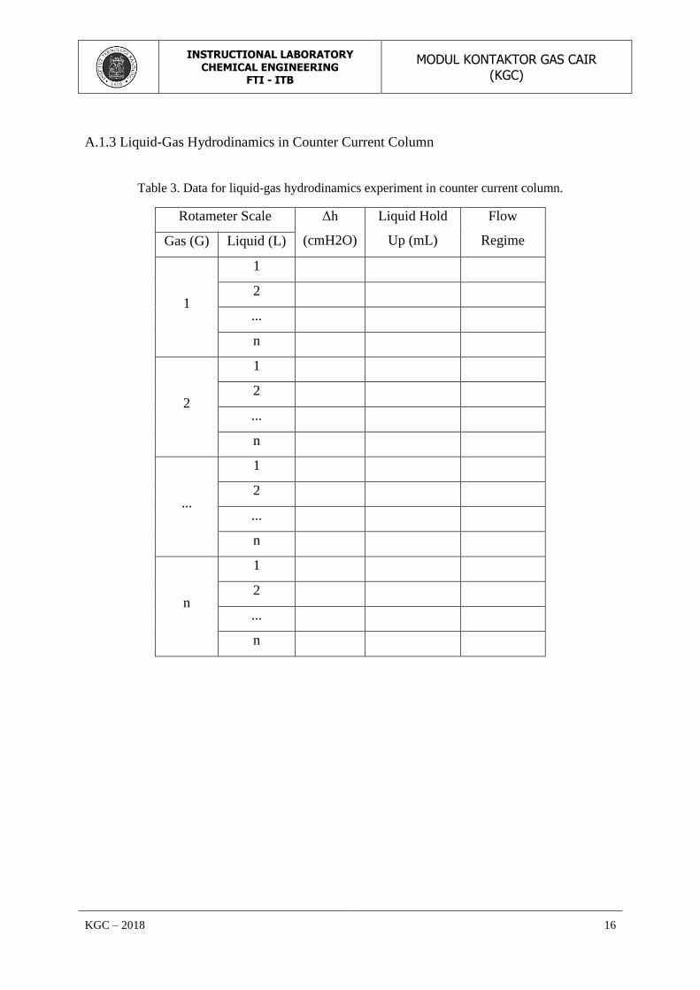
A.1.3 Liquid-Gas Hydrodinamics in Counter Current Column
Table 3. Data for liquid-gas hydrodinamics experiment in counter current column.
Rotameter Scale Δh
(cmH2O)
Liquid Hold
Up (mL)
Flow
Regime Gas (G) Liquid (L)
1
1
2
...
n
2
1
2
...
n
...
1
2
...
n
n
1
2
...
n

INSTRUCTIONAL LABORATORY
CHEMICAL ENGINEERING FTI - ITB
MODUL KONTAKTOR GAS CAIR (KGC)
KGC – 2018 17
A.2 Experiment on Co-current Column
A.2.1 Gas flowrate in co-current column.
Table 4. Data for determining gas flowrate in co-current column.
Scale Volume (L) Time (s)
1
2
3
4
...
n
A.2.2 Liquid flowrate in co-current column.
Table 5. Data for determining liquid flowrate in co-current column.
Scale Volume (L) Time (s)
1
2
3
4
...
n
INSTRUCTIONAL LABORATORY
CHEMICAL ENGINEERING FTI - ITB
MODUL KONTAKTOR GAS CAIR (KGC)
KGC – 2018 18
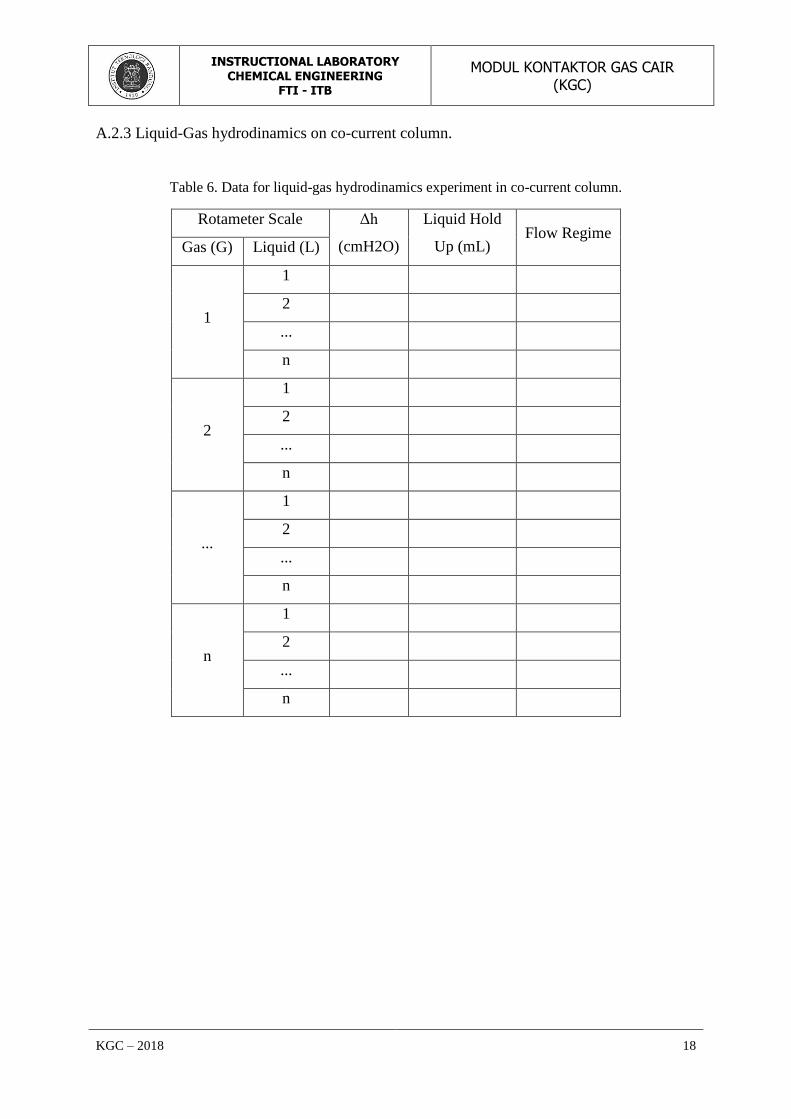
A.2.3 Liquid-Gas hydrodinamics on co-current column.
Table 6. Data for liquid-gas hydrodinamics experiment in co-current column.
Rotameter Scale Δh
(cmH2O)
Liquid Hold
Up (mL) Flow Regime
Gas (G) Liquid (L)
1
1
2
...
n
2
1
2
...
n
...
1
2
...
n
n
1
2
...
n
INSTRUCTIONAL LABORATORY
CHEMICAL ENGINEERING FTI - ITB
MODUL KONTAKTOR GAS CAIR (KGC)
KGC – 2018 19
B. Calculation Procedure
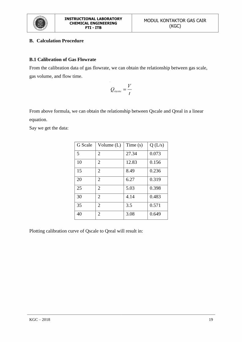
B.1 Calibration of Gas Flowrate
From the calibration data of gas flowrate, we can obtain the relationship between gas scale,
gas volume, and flow time.
From above formula, we can obtain the relationship between Qscale and Qreal in a linear
equation.
Say we get the data:
G Scale Volume (L) Time (s) Q (L/s)
5 2 27.34 0.073
10 2 12.83 0.156
15 2 8.49 0.236
20 2 6.27 0.319
25 2 5.03 0.398
30 2 4.14 0.483
35 2 3.5 0.571
40 2 3.08 0.649
Plotting calibration curve of Qscale to Qreal will result in:

INSTRUCTIONAL LABORATORY
CHEMICAL ENGINEERING FTI - ITB
MODUL KONTAKTOR GAS CAIR (KGC)
KGC – 2018 20
Then we obtained following equation
Qreal = 0,0165 Qscale – 0,0107
Jika Q scale = 3, then the real gas flowrate in L/s is:
Qreal = 0,0165 x 3 – 0,0107 = 0,0388 L/s
B.2 Calibration of Liquid Flowrate
From the calibration data of gas flowrate, we can obtain the relationship between liquid scale,
liquid volume, and flow time.
From above formula, we can obtain the relationship between Qscale and Qreal in a linear
equation.
Say we get the data:
Q scale Volume (L) Time (s) Q (L/s)
62 0.17 5.39 0.032
66 0.17 4.98 0.034
74 0.17 4.18 0.041
76 0.17 4.11 0.041
80 0.17 3.44 0.049
84 0.17 3.13 0.054
88 0.17 2.9 0.059
92 0.17 2.77 0.061

INSTRUCTIONAL LABORATORY
CHEMICAL ENGINEERING FTI - ITB
MODUL KONTAKTOR GAS CAIR (KGC)
KGC – 2018 21
98 0.17 2.5 0.068
Plotting calibration curve of Qscale to Qreal will result in:
Then we obtain the following equation:
Qreal = 0,0011 Qscale – 0,0363
Jika Qscale = 60, then real liquid flowrate in L/s is:
Qreal = 0,0011 *60 – 0,0363 = 0,0297 L/s
B.3 Determining Gas Mass Flux
Equation used:
where: ρG = air density
QG = air volumetric flowrate
A = column cross-sectional area
Then for QG = 0,0388 L/s, we obtain:
B.4 Determining Liquid Mass Flux

INSTRUCTIONAL LABORATORY
CHEMICAL ENGINEERING FTI - ITB
MODUL KONTAKTOR GAS CAIR (KGC)
KGC – 2018 22
where: ρL = liquid density
QL = liquid volumetric flowrate
A = luas penampang kolom
Then for QL = 0,0297 L/s we obtain:
L = 21,343 kg/m3.s
B.5 Determining Pressure Difference
Equation used:
ΔP = Δh
dimana: ΔP = pressure difference
ρL = liquid density (water)
g = gravitational acceleration
Δh = height difference in manometer
If we know that
ρL (at T experiment) = 996,757 kg/m3
g = 9,8 m/s2
Δh (measured in experiment) = 7,4 cm
Then
B.6 Determining % Liquid Hold-Up
If we obtain liquid hold up of 860 mL in 2L overall column volume after we turn off the gas
flow, the the %HU is :

INSTRUCTIONAL LABORATORY
CHEMICAL ENGINEERING FTI - ITB
MODUL KONTAKTOR GAS CAIR (KGC)
KGC – 2018 23
INSTRUCTIONAL LABORATORY
CHEMICAL ENGINEERING FTI - ITB
MODUL KONTAKTOR GAS CAIR (KGC)
KGC – 2018 24
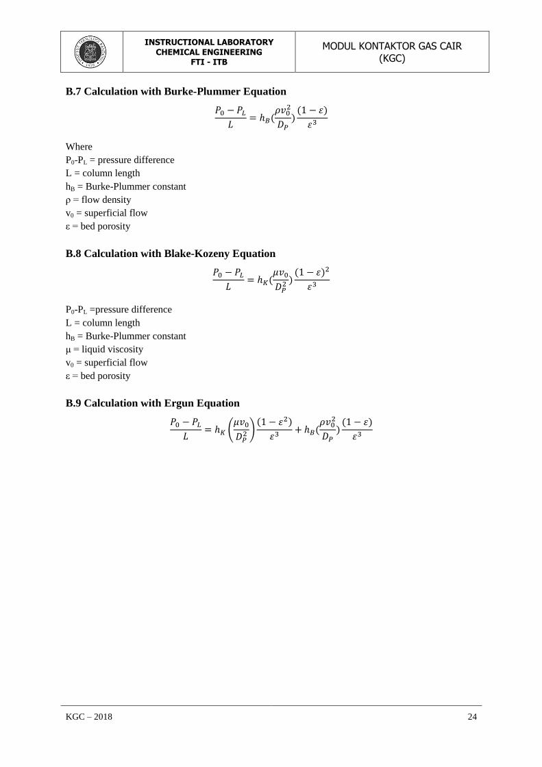
B.7 Calculation with Burke-Plummer Equation
Where
P0-PL = pressure difference
L = column length
hB = Burke-Plummer constant
ρ = flow density
v0 = superficial flow
ε = bed porosity
B.8 Calculation with Blake-Kozeny Equation
P0-PL =pressure difference
L = column length
hB = Burke-Plummer constant
μ = liquid viscosity
v0 = superficial flow
ε = bed porosity
B.9 Calculation with Ergun Equation
(
)

INSTRUCTIONAL LABORATORY
CHEMICAL ENGINEERING FTI - ITB
MODUL KONTAKTOR GAS CAIR (KGC)
KGC – 2018 25
C. Specification and Literature Data
C.1 Physical Properties of Water
(source : Geankoplis, C. J., 1993, Transport Process and Unit Operations, 3rd
ed., New
Jersey : Prentice-Hall. hal. 862.)
C.2 Other constant value
g (gravitational acceleration) = 9.8 m/s2
ρ mercury = 13.5 kg/m3
Mr air = 28.97 g/mol
R (gas constant) = 8314.34 m3.Pa/kg mol K
INSTRUCTIONAL LABORATORY
CHEMICAL ENGINEERING FTI - ITB
MODUL KONTAKTOR GAS CAIR (KGC)
KGC – 2018 26
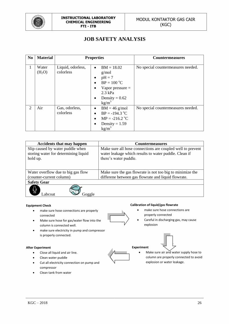
JOB SAFETY ANALYSIS
No Material Properties Countermeasures
1 Water
(H2O)
Liquid, odorless,
colorless BM = 18.02
g/mol
pH = 7
BP = 100 oC
Vapor pressure =
2.3 kPa
Density = 0.62
kg/m3
No special countermeasures needed.
2 Air Gas, odorless,
colorless BM = 46 g/mol
BP = -194.3 oC
MP = -216.2 oC
Density = 1.59
kg/m3
No special countermeasures needed.
Accidents that may happen Countermeasures
Slip caused by water puddle when
storing water for determining liquid
hold up.
Make sure all hose connections are coupled well to prevent
water leakage which results to water puddle. Clean if
there’s water puddle.
Water overflow due to big gas flow
(counter-current column)
Make sure the gas flowrate is not too big to minimize the
differene between gas flowrate and liquid flowrate.
Safety Gear
Labcoat Goggle
Equipment Check
make sure hose connections are properly
connected
Make sure hose for gas/water flow into the
column is connected well.
make sure electricity in pump and compressor
is properly connected.
Calibration of liquid/gas flowrate
make sure hose connections are
properly connected
Careful in discharging gas, may cause
explosion
Experiment
Make sure air and water supply hose to
column are properly connected to avoid
explosion or water leakage.
After Experiment
Close all liquid and air line.
Clean water puddle
Cut all electricity connection on pump and
compressor
Clean tank from water

INSTRUCTIONAL LABORATORY
CHEMICAL ENGINEERING FTI - ITB
MODUL KONTAKTOR GAS CAIR (KGC)
KGC – 2018 27
Problems that may occur :
1. Very small pressure difference can be observed due to manometer giving less
sensitive reading.
2. Air or water got into the manometer, causing it unable to read the pressure accurately.
Asisten Pembimbing Koordinator Lab TK
Related Documents


![[KGC 2012]Boost.asio를 이용한 네트웍 프로그래밍](https://static.cupdf.com/doc/110x72/55820726d8b42aa9498b4eda/kgc-2012boostasio-.jpg)