LINED EQUIPMENT // 3” 45° Footvalve 4” to 3” Hydraulic Footvalve 25mm Ball Valve 50mm Ball Valve 80mm Ball Valve 3" Butterfly Valve MK3 65mm Flanged Relief Valve 80mm Flanged Vacuum Vent Valve © Fort Vale Engineering Ltd. 2016 CATALOGUE REVISION_02-26.01.16 ®

Welcome message from author
This document is posted to help you gain knowledge. Please leave a comment to let me know what you think about it! Share it to your friends and learn new things together.
Transcript
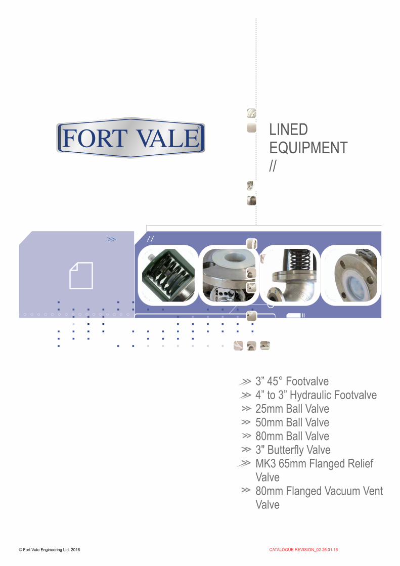
LINED EQUIPMENT//
3” 45° Footvalve4” to 3” Hydraulic Footvalve25mm Ball Valve50mm Ball Valve80mm Ball Valve3" Butterfly ValveMK3 65mm Flanged Relief Valve80mm Flanged Vacuum VentValve
© Fort Vale Engineering Ltd. 2016 CATALOGUE REVISION_02-26.01.16
®

THIS PAGE IS INTENTIONALLY BLANK

FOOT061 REV04-21.01.16
Fitting Details
Data Halar® Lined 3” 45° Footvalve®
RangeSpecification
© Fort Vale Engineering Ltd. 2016
Halar® Lined 3” 45° Footvalve - inlet flange drilled 8 x 14mm holes equi-spaced on a 178mm PCD; outlet flange drilled 4 x 17mm holes equi-spaced on a 160mm PCD. Valve manufactured in stainless steel and fitted with a Viton main seal. Bayonet cap and spring coated with Halar®, poppet lined with PFA and lifting plunger encased in PTFE bellows.
Options - Other main seal materials are available. Optional remote operating lever. Range of lined discharge valves and vent valves available for use with corrosive cargoes. Pneumatically actuated version.
Weight 10.5 Kg Design Pressure (MAWP) 3 Bar (43.5 PSI)Test Pressure 4 Bar (58.0 PSI)Design Temperature -20°C to +100°C (-4°F to +212°F)
Approved to BS EN14433.
Part Number : 82L/1000X
Associated Parts
Associated Parts Part No.
Remote operating lever 324/8927 Retaining collar for remote lever 324/8928 Tank pad suitable for lining 324/9000L Stud kit 324/2055 Bolting kit – 6 hole outlet 360/0300 Bolting kit – 4 hole outlet 311/3000 Inlet gasket – 8 hole 5005-015 Outlet gasket – 6 hole 5005-169 Outlet gasket 5005-049
Part No. Description
82L/1000V Halar® lined 3” 45° Footvalve, Viton seal 82L/1000P Halar® lined 3” 45° Footvalve, PTFE seal 82L/1000K Halar® lined 3” 45° Footvalve, Kalrez seal
82L/1000XPN Halar® lined 3” 45° Footvalve - pneumatically actuated.
143.7
19.124.4
103.2
Ø20
1.2
Ø79.9
23.6 144.0
Ø126.9
Ø15
9.1
4 HOLES Ø17MM EQUI-SPACED ON A 160.0MM PCD
8 HOLES Ø14MM EQUI-SPACED ON A 177.8MM PCD
235.8
Page 1

FOOT062 REV02-17.07.14
Parts drawing
Data Halar® Lined Footvalve3” 45° ®
© Fort Vale Engineering Ltd. 2014
SELF ADHESIVE DECAL - PART NO. 326/0300Text in English, German and French
NOTE : Material and part number varies according to valve specification.
Item Description Part No.
1 Lined body assembly 826/1135 2 Viton O ring *See Note 5005-624 3 Lifting plunger 826/1133 4 Sealing bellows 826/1137 5 Viton poppet seal *See Note 826/1136 6 PFA lined poppet 826/1138P 7 Halar® coated spring 5104-875L 8 Halar® lined bayonet cap 826/1126FL 9 M6 cap screw (7) 5111-034 10 Dust cover 826/1139C 11 Spring washer (7) 5113-044 12 Plunger bearing 826/1127 13 M6 cap screw (3) 5111-108 14 Plain washer (2) 5113-015 15 Link arm 826/1132 16 Pivot pin (2) 826/1141 17 Retaining washer 20370 18 Countersunk bolt 5111-147 19 Handle 330/5018 20 Bearing ring 826/1143 21 Spindle 826/1128 22 Crank 826/1129 23 Bearing bush 826/1131 24 Extractable pin 826/1142
12
3
4
5
6
7
8
10
9
11
9
121014
131516
1817
19
20
21
2223
24
Page 2

FOOT065 REV00-20.10.08
Fitting Details
DataTM
Associated Parts
Halar Lined Product RangeSpecification
© Fort Vale Engineering Ltd. 2008
Halar Lined 4” to 3” Hydraulic Highlift Footvalve
Options
- inlet flange drilled 8 x 14mm holes equi-spaced on a 184mm PCD (4” TTMA). Outlet flange drilled 8 x 11mm holes equi-spaced on a 124mm PCD (3” TTMA). Hydraulic actuator with 1/8” NPT connections. Valve manufactured in 304/316 stainless steel fitted with a Viton main seal. All parts in contact with the cargo lined with Halar and lifting rod encased in PTFE bellows.
- other Halar lined products available : 3” 45° Footvalve; 3” Ball valve; 2” Ball valve.
Weight 15 Kg Design Pressure (MAWP) 4 Bar (58.0 PSI)Test Pressure 6 Bar (87.0 PSI)Design Temperature -20°C to +100°C
(-4°F to +212°F)
Part Number : 299/L710GS
Part No. Description
82L/1000 Halar lined 3” 45° Footvalve 370/L100 Halar lined 2” Ball valve 360/L050X Halar lined 3” Ball valve
Part Number Description
299/0102 4” TTMA Tank pad 5005-441 Inlet gasket - CNAF/Teflon envelope 5005-445 Outlet gasket - CNAF/Teflon envelope
Halar Lined 4” to 3” Hydraulic Highlift Footvalve
8 HOLES Ø 11.0 EQUI-SPACEDON A 124.0 PCD.(3” TTMA)
22.5°
Ø 209.6 (8.25”)
Ø 1
09.5
(4.3
1”)
Ø 1
43.0
(5.6
3”)
13.2(0.52”)
277.3
(10.9
2”)
27.9
(1.1
0”)
Ø 8
1.8
(3.2
2”)
Page 3

THIS PAGE IS INTENTIONALLY BLANKPage 4

BALL024 REV04-26.06.14
Parts drawing
DataPFA Lined 25mm Reduced Bore
Flanged Airline Ball Valve
®
Associated Parts
Range
SpecificationFitting Details
© Fort Vale Engineering Ltd. 2014
PFA Lined 25mm Reduced Bore Flanged Airline Ball Valve
Options
- 125mm PCD; outlet flange (tank connection) drilled 4 x 11mm holes on a 103.5mm PCD. Valve manufactured in stainless steel with PTFE main seal. All parts in contact with the cargo lined with PFA.
- range of PFA lined ball valves (See RANGE)
inlet flange drilled 4 x 18mm slots on a 100mm to
Weight 5.3 KgDesign Pressure (MAWP) 6.9 Bar (100 PSI)Test Pressure 10.3 Bar (150 PSI)Design Temperature Range -40°C to +200°C
-40°F to +392°F
Valve complies with EN14432:2006 and RID norms.
Part No. Description
530/P100 25mm PFA lined reduced bore ball valve 370/P100 50mm PFA lined full bore ball valve 360/P030X 80mm PFA lined full bore ball valve
1
2
3
4
5
6
7
8
9
1011
12
13
Part number : 530/P100
Item Description Part No.
1 M5 socket screw 5111-111 2 Retaining washer 20370/5 3 Handle 530/0020/1 4 M6 button screw (4) 5121-013 5 Stuffing clamp 530/1014 6 Seal carrier for lining 530/1013 7 Perfluoroelastomer O ring 5005-586 8 Perfluoroelastomer O ring 5005-384 9 Fortyt O ring 5005-601 10 PFA lined body 530/P110 11 PFA lined ball & stem 530/1010L 12 PFA lined clamp plate 530/1011PL 13 PTFE front & rear seal (2) 530/0024
Ø 38.1
Ø 25.0
23.6
Ø 80.4
80.5
Ø 78.0
Ø 152.0
Ø 127.0
45°
108.9
OUTLET - 4 HOLES Ø 11.0 EQUI-SPACED ON A 103.5 PCD.
INLET - 4 SLOTS Ø 18.0EQUI-SPACED ON A 100 TO 125 PCD.
Part No. Associated Parts
350/0024 Tank weld-in pad 355/1250 Stud kit 530/8053CM Blind flange 5005-348 Solid PTFE outlet gasket 311/3510 Bolting kit
Page 5

BALL027 REV05-24.04.17
Associated Parts
Range
SpecificationFitting Details
© Fort Vale Engineering Ltd. 2017
PFA Lined 50mm Full Bore Flanged Ball Valve - inlet flange drilled 4 x 18mm holes on a 126mm PCD; outlet flange drilled 4 x 18mm slots on a 120.7mm to 127mm PCD. Valve manufactured in stainless steel with PTFE main seal. All parts in contact with the cargo lined with PFA.
Options - range of PFA lined ball valves (See RANGE)
Weight 12.15 KgDesign Pressure (MAWP) 6.9 Bar (100 PSI)Test Pressure 10.3 Bar (150 PSI)Design Temperature Range -40°C to 200°C (-40°F to 392°F)
Valve complies with EN14432 and RID norms.
Part number : 370/P100
Fitting Details
Part No. Description
530/P100 25mm PFA lined reduced bore ball valve 370/P100 50mm PFA lined full bore ball valve 360/P030X 80mm PFA lined full bore ball valve
Part No. Associated Parts
311/3790 Stud kit 311/3590 Bolting kit 370/4239PFA PFA lined blind flange
SEAL KITPart number 370/P100SK contains all parts marked
Item Description Part No.
1 M5 screw 5111-113 2 Retaining washer 20370/5 3 Handle 370/3306/1 4 Stop pin (2) 370/P107 5 Stuffing plate 370/P114 6 Seal carrier 370/P113 7 Viton O ring ORB115VL 8 Viton O ring ORB121VL 9 Perfluoroelastomer O ring 5005-214PER 10 PFA lined body 370/P110 11 PTFE ball seal (2) 370/P115 12 Fortyt O ring (2) ORM0580400F0 13 PFA lined obturator 370/P101 14 M8 cap screw (4) 5111-010 15 PFA lined clamp plate 370/P111 16 Perfluoroelastomer O ring (2) 5005-370P 17 M6 cap screw (2) 5111-015
DataPFA Lined 50mm Full Bore
Flanged Ball Valve
®
21.0Ø 50.0
Ø 50.7
67.0
Ø 100.6
Ø 165.0
Ø 165.0Ø 105.0
223.9
67.0
131.0
45°
142.9
4 SLOTS Ø18 EQUI-SPACED ON A 120.7 TO 127.0 PCD
1
2
3
4
5
10
13
1415
17
6
7
8
16
1112
9
Page 6

BALL025 REV00-21.09.09
Fitting Details
DataTM
PFA Lined 80mm Full Bore Ball Valve
Associated Parts
RangeSpecification
© Fort Vale Engineering Ltd. 2009
PFA Lined 80mm Full Bore Ball Valve
Options
- 4 x 18mm holes on a 160mm PCD; outlet flange drilled 4 x 18mm slots equi-spaced on a 146 to 160mm PCD. (3” BSTD to DIN80) Left hand operated with TIR to handle. Valve manufactured in stainless steel with PTFE main seal. All parts in contact with the cargo lined with PFA.
- right hand operated version. Range of PFA lined ball valves (See RANGE)
inlet flange drilled
Part No. Description
530/P100 25mm PFA lined reduced bore ball valve 370/P100 50mm PFA lined full bore ball valve 360/P030X 80mm PFA lined full bore ball valve
Weight 12.9 KgDesign Pressure (MAWP) 6.9 Bar (100 PSI)Test Pressure 10.34 Bar (150 PSI)Design Temperature Range -40°C to 130°C
-40°F to 266°F
Valve complies with EN14432:2006 and RID norms.X in part number denotes whether left (L) or right (R) hand valve.
Example shown : 360/P030L
117.8
20.727.4
170.0
45.0°
4 HOLES Ø 18MM SPACED AS SHOWN ON A 160MM PCD.
378.2
Ø 1
94.0
Ø 1
40.0
Ø 7
4.0
Ø 1
13.0
Ø 1
97.0
POSITION CLAMP PLATE TO ACHIEVE HANDING. (CLAMP PLATE SHOWN IN LEFT HAND POSITION)
OUTLET FLANGE 4 X 18MM SLOTS EQUI-SPACED ON A 146MM (3”BSTD) TO 160MM (DIN80) PCD
Part No. Associated Parts
368/0500P 3” BSP PFA lined outlet flange 368/8047L 3” BSP Halar lined eccentric outlet flange 5005-417 Solid PTFE outlet gasket 360/8095P PFA lined blind flange
Page 7

BALL026 REV02-24.04.17
Parts drawing
Data®
© Fort Vale Engineering Ltd. 2017
PFA Lined 80mm Full Bore Ball Valve
Item Description Part No.
1 M8 hex bolt (4) 5111-046 2 M8 spring washer (4) 5113-003 3 M12 locking nut 5112-007 4 M12 washer 5123-003 5 Handle 360/3416 6 20mm washer (2) 5113-041 7 Clamp plate 360/3406/1 8 Stainless steel stuffing collar 360/3464 9 PTFE O ring (3) 5005-654 10 PFA lined spindle 360/3422PL 11 PFA lined body 360/P020 12 PTFE front & rear seal (2) 360/3402/5 13 PFA coated ball 360/3401PL 14 PFA lined clamp plate 360/3462PL 15 M6 countersunk bolt (3) 5111-030 16 Bottom stuffing collar 360/3413/1 17 Top stuffing collar 360/3412/1
SEAL KITPart number 360/P0SK contains all parts marked
1
2
3
4
5
6
7
8
9
10
11
12
12
13
14
15
16
17
Page 8

BUTT036 REV01-01.04.14
Fitting Details
DataPFA Lined
Butterfly Valve3” Clamped ®
Associated Parts
RangeSpecification
© Fort Vale Engineering Ltd. 2014
PFA Lined 3” Clamped Butterfly Valve
Options
- left hand operated with TIR to handle and padlock facility. Valve manufactured in stainless steel with PFA body liner and fitted with a PFA lined closure plate and spindle assembly.
- PFA lined 2” clamped butterfly valve. Range of lined discharge valves and relief valves available - please contact our sales department for further details.
Weight 3.69 KgDesign Pressure (MAWP) 4 Bar (58 PSI)Test Pressure 6 Bar (87 PSI)Design Temperature -40°C to 200°C
(-40°F to 392°F)
Approved to BS EN14432
Part Number Description
368/8047L Halar lined 3” BSP outlet flange 10303SS 3” BSP stainless steel cap with chain 10329P/1 PTFE disc seal to suit 3” cap
Part No. Description
258/P700 PFA lined 2” clamped butterfly valve 358/P700 PFA lined 3” clamped butterfly valve
Part number : 358/P700
202.7
160.3
Ø11
0.5
11.0
40.0
Page 9

BUTT037 REV00-02.04.14
DataPFA Lined
Butterfly Valve3” Clamped ®
© Fort Vale Engineering Ltd. 2014
Parts Drawing
Item Description Part No.
1 Split ring 368/0011 2 Handle lever 368/9837 3 Handle 368/0050 4 Handle spring 368/0012 5 Handle location pin 368/0010 6 M8 cap screw (2) 5111-148 7 M8 plain washer (2) 5113-005 8 Stuffing clamp 368//0040 9 Stuffing clamp bush 368/0301 10 M8 spring washer (2) 5113-003 11 M8 full nut (2) 5112-001 12 Body assembly 358/P253 13 Top guide bush 358/P236 14 Belleville washer (6) 5113-052 15 PFA lined spindle/closure plate 358/P235 16 Bottom thrust bearing 358/P233/1 17 Backing rubber (2) 358/P257 18 PFA body seal 358/P250 19 Perfluoroelastomer o ring 5005-216PER 20 Stem seal housing 358/P233 21 Retaining washer 20370 22 M8 bolt 5111-030
1
2
3
4
5
6
7
8
9
10
11
12
12
13
14
15
16
17
17
18
19
20
21
22
Page 10

REL131 REV03-15.11.17
Fitting Details
Associated Parts
RangeSpecification
© Fort Vale Engineering Ltd. 2017
Lined 65mm NB Flanged MK3 Super Maxi Relief Valve- flange drilling to suit customer requirements (See Range) Suitable for a pressure setting of between 3 PSI to 66 PSI (0.21 to 4.55 Bar) and a vacuum setting of between 0.5”Hg to 6.2”Hg (0.02 to 0.21 Bar). Manufactured with PFA lined body, pressure plate and vacuum poppet, Halar® coated pressure spring(s) and high nickel alloy vacuum spring. Fitted with Fortyt seal as standard. May be supplied with or without gauge tapping.
Options - pressure only version. 80mm NB range. Viton seals available.
Weight 5.8 KgDesign Temperature Range Fortyt : -55°C to 150°C Viton : -18°C to 150°CMinimum Design Metal Temperature : -29°C (-55°C on request)
Design approval by Lloyds Register of Shipping.
Test certificates supplied as standard. Please see separate data sheets for details on flow rates.
Tests may be witnessed and valves individually stamped by an independent inspectorate by arrangement.
Visual inspection and service (where necessary) is recommended on a 6 monthly basis.
Part No. Flange Drilling Gauge tap 0U3/XXXXX6SLB 4 slots on Ø 145 - 152.4 NONE 0U3/XXXXX6SL 4 slots on Ø 145 - 152.4 ¼” BSP 0U3/XXXXX659 2.5” ASA 150
3/8” BSP
0U3/XXXXX65N 3” ASA 150 ¼” NPT 0U3/XXXXX658 3” ASA 150 NONE 0U3/XXXXX657 DIN 80 PN 10 ¼” BSP 0U3/XXXXX655 3” ASA 150 ¼” BSP 0U3/XXXXX654 2.5” ASA 150 ¼” BSP 0U3/XXXXX653 3” TABLE D ¼” BSP 0U3/XXXXX651 DIN 80 PN 6 ¼” BSP 0U3/XXXXX650 DIN 65 PN 10 ¼” BSP
Part number : 0U3/XXXXX65X
4.0
111.2
Ø 187.0
Ø 113.8
Ø 68.1
2.5
17.0
1.5
Ø 120.0
MAY BE SUPPLIED WITH OR WITHOUT GAUGE TAPPING. SEE RANGE.
GA
UG
E
TA
P.
Data® Lined MK3 65mm Flanged Pressure/
Vacuum Super Maxi Relief Valve
Part No. Description
921/07BBSP 0-100 PSI pressure gauge, bottom entry, brass internal parts
921/07RBSP 0-100 PSI pressure gauge, rear entry, brass internal parts
920/07BBSP 0-100 PSI pressure gauge, bottom entry, stainless steel internal parts
176/2900 Removable clamped gauze 862/XXXX 65mm bursting disc 311/3700 Stud kit ( 4 x M16) 176/3245L Tank weld in flange suitable for lining
Page 11

REL132 REV04-29.11.17
Parts Drawing
© Fort Vale Engineering Ltd. 2017
NOTE : Part numbers vary according to valve specification. Please contact Sales for further information.
1
2
3
4
5
6
7
8
9
10
11
12
13
Data® Lined MK3 65mm Flanged Pressure/
Vacuum Super Maxi Relief Valve
Item Description Part No.
1 Stainless steel plug 10978 2 Cap (See Note) 1860/0046XX 3 Locking grubscrew 5121-001
4 Halar® coated pressure spring pair (See Table 1)
6104-XXXX
5 M8 half nut (2) 5112-004 6 Vacuum spring pad 1860/0005
7 High nickel alloy vacuum spring (See Table 2)
7104-XXXH
8 High nickel alloy spring pad 10986/3H 9 PFA lined pressure plate (See Note) 1860/PX56XX
10 Fortyt pressure O ring 5005-101 11 PFA lined vacuum poppet 10983V/P 12 Fortyt vacuum O ring 5005-108H 13 PFA lined body (See Note) 1860/06XXU
TABLE 1
Pressure setting Halar® coated pressure spring(s)
31.8 PSI (2.19 Bar) 6104-252L 44.0 PSI (3.03 Bar) 6104-0090L (Pair) 53.8 PSI (3.71 Bar) 6104-0422L (Pair) 63.8 PSI (4.40 Bar) 6104-0485C (Pair)
TABLE 2
Vacuum setting High nickel alloy vacuum spring
0.5”Hg (0.02 Bar) 7104-001H 1”Hg (0.03 Bar) 7104-001H 1.5”Hg (0.05 Bar) 7104-002H 3”Hg (0.10 Bar) 7104-006H 6”Hg (0.21 Bar) 7104-012H
Page 12

REL139 REV03-26.04.18
DataPTFE Lined 80NB Flanged
Vacuum Vent Valve
®
SpecificationFitting Details
© Fort Vale Engineering Ltd. 2018
Weight 4.5 KgDesign Pressure (MAWP) 4 Bar (58 PSIG)Test Pressure 6 Bar (87 PSIG)Design Temperature Range -20°C to 150°C (-4°F to 302°F)
PTFE Lined 80mm NB Flanged Vacuum Vent Valve - flange drilling to suit customer requirements. (See Range) Suitable for a vacuum range of between 0.5”Hg to 6.2”Hg (0.02 Bar to 0.21 Bar) Manufactured in stainless steel fitted with Fortyt seal as standard. Wetted parts of body fitted with a PTFE liner. Poppet manufactured in high nickel alloy. Fitted with weatherproof cowl.
Options - Other seal materials are available. Various flange drilling options. Cowl with gauze. Non-lined 3” BSPF stainless steel version available.
Example shown : 81BF/X00XXXP
Associated Parts
Parts drawing
Note : Part number varies according to specification.
Range
i Operating Instructions available - OPIN27
Part No. Associated Parts
1780/0560GZ Weatherproof cowl to accept gauze ring 10206/2 Gauze ring to fit weatherproof cowl
Part No. Flange Drilling
81BF/X00XX0P DIN 65 PN10 81BF/X00XX1P DIN 80 PN6 81BF/X00XX3P 3.0” B.S. TABLE D 81BF/X00XX4P 2.5” ASA 150 81BF/X00XX5P 3.0” ASA 150 81BF/X00XX7P DIN 80 PN10
Item Description Part No.
1 Top Cap 1780/0580 2 Sockethead set screw 5121-001 3 Weatherproof cowl 1780/0560 4 Plain washer 5123-007 5 Spring locator 1780/0570 6 Continuity bush 1780/0571 7 Vacuum spring (See Note) 5104-XXX 8 Lined flanged body (See Note) 1780/080XX
9 Fortyt main seal 5005-679
Viton main seal 5005-299
10 Retaining pin 5118-020 11 High nickel alloy poppet 1780/0555H
VARIES
Ø199.9
116.5
1.4
16.8 Ø62.4 POPPET
CLEARANCE
Ø79.3
Ø122.7
12
3
4
5
6
7
8
11
10
9
Page 13

Fort Vale UKHead Office & Manufacturing PlantTel : +44 (0)1282 687120Fax : +44 (0)1282 687110Email : [email protected]
Fort Vale USATel : +1 281 471 8100Fax : +1 281 471 8116Email : [email protected]
Fort Vale NetherlandsTel : +31 (0)180 483333Fax : +31 (0)180 410797Email : [email protected]
Fort Vale Russian FederationTel : +7 916 682 0947Email : [email protected]
Fort Vale P.R. ChinaTel : +86 21 6442 1367Fax : +86 21 6442 1376Email : [email protected]
Fort Vale SingaporeTel : +65 6515 9950Fax : +65 6515 3034Email : [email protected]
Fort Vale AustraliaTel : +61 7 3310 4854Email : [email protected]
www.fortvale.com
All goods supplied will be subject to Fort Vale Engineering Ltd Terms and Conditions of Sale (Ref. FV4) which are available upon request, or may be viewed at www.fortvale.com.
Please note that this brochure and the contents herein remain the property of Fort Vale Engineering Limited.
This brochure may not be copied or reproduced, or the information contained herein divulged to any third party without the prior written permission of Fort Vale Engineering Limited.
Repair/refurbishment/resetting of Fort Vale valves may be carried out only by trained and authorised personnel. Fort Vale Engineering Limited shall not, in any circumstances, be liable for injuries, losses, expenses or damage, direct or consequential, sustained by the buyer or any person which may in any degree be attributable to the adoption, either by the buyer or any third party, of technical or other information, data or advice given on behalf of Fort Vale Engineering Limited or however otherwise caused in relation to the use of its products in accordance with Fort Vale Engineering Limited’s recommendation.
The specifications included in this catalogue are intended to be generic and must be interpreted as equivalent or functionally equivalent. The identification of many items is facilitated by illustrations (photographs and line drawings). The mention of, or reference to specific companies, national standards, or trade names, including those that might appear on the photographs, is intended for illustration purposes only. It does not imply an endorsement, preference or availability of any specific standard, brand or supplier.
The data and information contained herein is being provided for information only and without responsibility, and Fort Vale Engineering Limited makes no representations or warranties, either expressed or implied, as to the accuracy, completeness, or fitness for a particular purpose. Fort Vale Engineering Limited does not accept any responsibility or liability with regard to the reliance on, or use of this data and information.
REV10_19.03.18
®
© Fort Vale Engineering Ltd. 2018
Related Documents