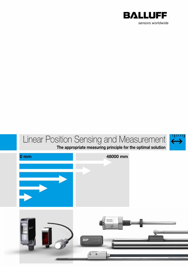
Linear Position Sensing and Measurement The appropriate measuring principle for the optimal solution 48000 mm 0 mm

Welcome message from author
This document is posted to help you gain knowledge. Please leave a comment to let me know what you think about it! Share it to your friends and learn new things together.
Transcript
Balluff GmbH Schurwaldstrasse 973765 Neuhausen a.d.F.GermanyTel. +49 7158 173-0Fax +49 7158 [email protected]
www.balluff.com
Linear Position Sensing and MeasurementThe appropriate measuring principle for the optimal solution
Doc. No. 893812/Mat. No. 228733 E Edition 1211; subject to changes.
Line
ar P
ositi
on S
ensi
ng a
nd M
easu
rem
ent
Object Detection
Linear Position Sensing and Measurement
Condition Monitoring and Fluid Sensors
Industrial Identification
Industrial Networking and Connectivity
Accessories
Systems and Service
48000 mm0 mm

For more information, visit us online!2
Fully exploit the potential
of high quality: with superior
position measurement tech-
nology for more efficiency.
With over 50 years of sensor experience, Balluff is a leading global
sensor specialist with its own line of connectivity products for every
area of factory automation. Balluff is based in Germany and has a
tight international network of 54 representatives and subsidiaries.
Balluff stands for comprehensive systems from a single source,
continuous innovation, state-of-the-art technology, highest quality,
and greatest reliability. That's not all: Balluff also stands for excep-
tional customer orientation, customized solutions, fast worldwide
service, and outstanding application assistance.
High-quality, innovative products tested in our own accredited
laboratory and a quality management system certified according
to DIN ISO 9001 (EN 2008) form a secure foundation for optimized
added value for our customers.
Whether electronic and mechanical sensors, rotary and linear
transducers, identification systems or optimized connection tech-
nology for high-performance automation, Balluff not only masters
the entire technological variety with all of the different operating
principles, but also provides technology that fulfills regional quality
standards and is suitable for use worldwide. Wherever you are
in the world, Balluff technology is never far away. You won't have
to look far for your nearest Balluff expert.
Balluff products increase performance, quality and productivity
around the world every day. They satisfy prerequisites for meeting
demands for greater performance and cost reductions on the global
market. Even in the most demanding areas. No matter how stringent
your requirements may be, Balluff delivers state-of-the-art solutions.
3www.balluff.com
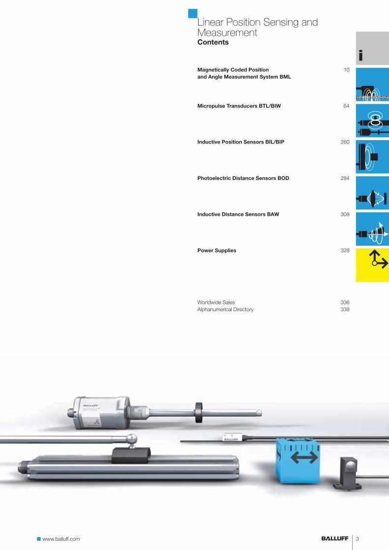
Worldwide Sales 336
Alphanumerical Directory 338
308Inductive Distance Sensors BAW
328Power Supplies
10Magnetically Coded Position
and Angle Measurement System BML
64Micropulse Transducers BTL/BIW
260Inductive Position Sensors BIL/BIP
284Photoelectric Distance Sensors BOD
Linear Position Sensing and MeasurementContents
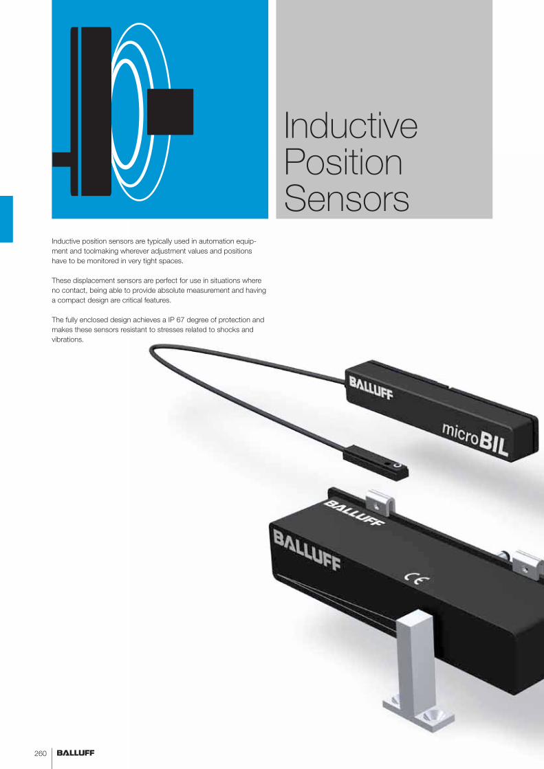
Inductive position sensors are typically used in automation equip-
ment and toolmaking wherever adjustment values and positions
have to be monitored in very tight spaces.
These displacement sensors are perfect for use in situations where
no contact, being able to provide absolute measurement and having
a compact design are critical features.
The fully enclosed design achieves a IP 67 degree of protection and
makes these sensors resistant to stresses related to shocks and
vibrations.
Inductive Position Sensors
260

www.balluff.comwww.balluff.com
SMARTSENS
Inductive Position SensorsContents
Inductive position sensors
Applications 262
Summary 264
Magneto-inductive position sensors BIL 266
Inductive position sensors BIP 274
Basic information and definitions 280
Basic information and definitions can be found on page 280.
261

For more information, visit us online!262
Inductive Position SensorsApplications
BIL
Balluff magneto-inductive position sensors detect positions up
to 160 mm away. Analog position sensors BIL measure without
contact and absolutely using a passive magnet. The compact
design means these sensors can be easily integrated into the ap-
plication even when mounting space is extremely tight.
Micro-BIL
The Micro-BIL detects the absolute position on pneumatic miniature
grippers or compact cylinders using integrated permanent magnets;
the sensor element can be easily
installed in the T-slot. The analog output signal allows you to indi-
vidually and flexibly detect end-of-travel and intermediate positions
on gripper jaws or pistons.
263www.balluff.com
Inductive Position SensorsApplications
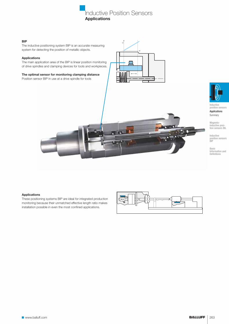
BIP
The inductive positioning system BIP is an accurate measuring
system for detecting the position of metallic objects.
Applications
The main application area of the BIP is linear position monitoring
of drive spindles and clamping devices for tools and workpieces.
The optimal sensor for monitoring clamping distance
Position sensor BIP in use at a drive spindle for tools
Applications
These positioning systems BIP are ideal for integrated production
monitoring because their unmatched effective length ratio makes
installation possible in even the most confined applications.
Inductive position sensorsApplicationsSummary
Magneto- inductive posi-tion sensors BIL
Inductive position sensors BIP
Basic Information and Definitions
For more information, visit us online!264
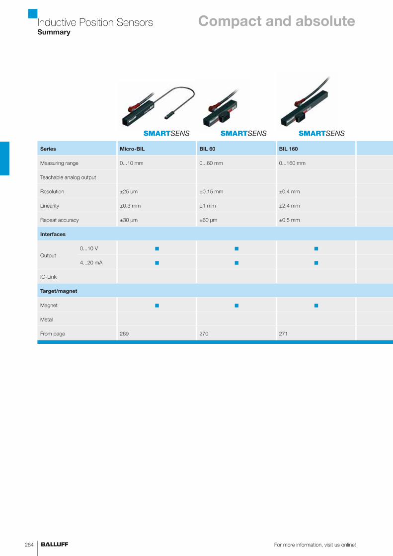
Inductive Position SensorsSummary
Series Micro-BIL BIL 60 BIL 160
Measuring range 0...10 mm 0...60 mm 0...160 mm
Teachable analog output
Resolution ±25 μm ±0.15 mm ±0.4 mm
Linearity ±0.3 mm ±1 mm ±2.4 mm
Repeat accuracy ±30 μm ±60 μm ±0.5 mm
Interfaces
Output
0...10 V ■ ■ ■
4...20 mA ■ ■ ■
IO-Link
Target/magnet
Magnet ■ ■ ■
Metal
From page 269 270 271
SMARTSENS SMARTSENS SMARTSENS
Compact and absolute
265www.balluff.com
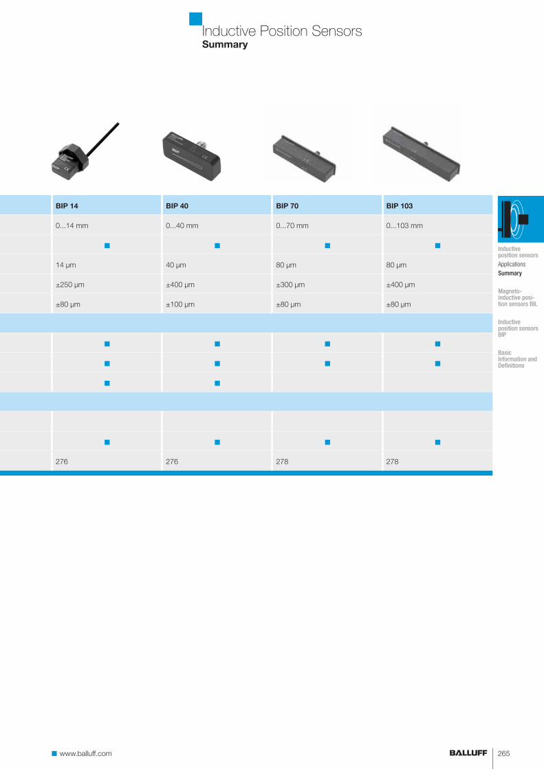
BIP 14 BIP 40 BIP 70 BIP 103
0...14 mm 0...40 mm 0...70 mm 0...103 mm
■ ■ ■ ■
14 μm 40 μm 80 μm 80 μm
±250 μm ±400 μm ±300 μm ±400 μm
±80 μm ±100 μm ±80 μm ±80 μm
■ ■ ■ ■
■ ■ ■ ■
■ ■
■ ■ ■ ■
276 276 278 278
Inductive Position SensorsSummary
Inductive position sensorsApplications
Summary
Magneto- inductive posi-tion sensors BIL
Inductive position sensors BIP
Basic Information and Definitions
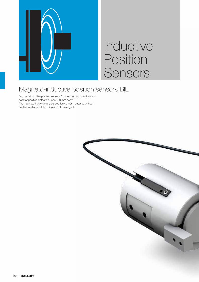
Magneto-inductive position sensors BIL are compact position sen-
sors for position detection up to 160 mm away.
The magneto-inductive analog position sensor measures without
contact and absolutely, using a wireless magnet.
Inductive Position Sensors
Magneto-inductive position sensors BIL
266

www.balluff.comwwwwww.balluff.com
SMARTSENS
Magneto-inductive Position Sensors BILContents
Magneto-inductive position sensors BIL
Summary 268
Micro-BIL, general data 269
BIL, general data 270
Accessories 272
267
For more information, visit us online!268
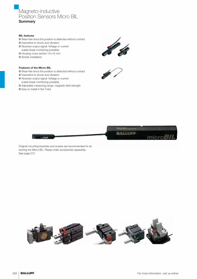
BIL features
■ Wear-free since the position is detected without contact
■ Insensitive to shock and vibration
■ Absolute output signal: Voltage or current
(cable break monitoring possible)
■ Housing cross-section 15×15 mm
■ Simple installation
Features of the Micro-BIL
■ Wear-free since the position is detected without contact
■ Insensitive to shock and vibration
■ Absolute output signal: Voltage or current
(cable break monitoring possible)
■ Adjustable measuring range, magnetic field strength
■ Easy to install in the T-slot
Magneto-inductive Position Sensors Micro BILSummary
Original mounting brackets and screws are recommended for at-
taching the Micro-BIL. Please order accessories separately.
See page 272

269www.balluff.com
Magneto-inductive Position Sensors Micro BILGeneral data
300 mm
Teach-in
Sensing surface
Connect either the voltage or current output.
Connection wiring diagram
Output signal Uout Voltage 0...10 V or
Output signal Iout Current 4...20 mA
Working range sw 0...10 mm
Linear range sI 0...10 mm
Ordering code BIL0002
Part number BIL ED0-B010P-02/30-S75
Supply voltage US At voltage output Uout: US = 15...30 V DC,
At current output Iout: US = 10...30 V DC
Field strength, axial Hn 10 kA/m typical
–3dB width of the axial field distribution, typical
(typical axial field strength – parallel to sensing surface)
2.5 mm
Residual ripple ≤ 10% of Ue
Rated insulation voltage Ui 75 V DC
Effective distance se 5 mm
Load resistance RL At voltage output Uout: RL = ≥ 2 kΩ,
At current output Iout: RL = ≤ 500 Ω
No-load supply current I0 at Ue ≤ 30 mA
Polarity reversal protected yes
Short-circuit protected yes
Ambient temperature Ta –10...70 °C
Repeat accuracy RBWN ≤ ±30 μm
Non-linearity ±0.3 mm
Temperature coefficient TC
In the optimum range
from 10...50 °C
Typical +4 μm/K
Min. +2 μm/K
max +10 μm/K
Power-on indicator yes
Programming indicator yes
Degree of protection as per IEC 60529 IP 67
Housing material PA fiberglass reinforced
Connection Plug connector
Approval cULus
Recommended connector BKS-S 74/BKS-S 75
Adjustment to different magnetic field
strengths is possible at the touch of a button.
The technical data refer to reference
measurements. Different grippers/cylinders
with differing magnetic fields may affect the
technical data.
becomes narrow
Inductive position sensors
Magneto- inductive posi-tion sensors BILSummaryMicro-BILBIL
Accessories
Inductive position sensors BIP
Basic Information and Definitions
For more information, visit us online!270
Connect either the voltage
or current output.
Do not connect
BIL EMD0.../BIL ED0...
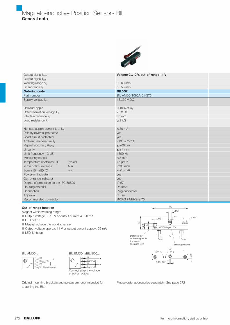
Out-of-range function
Magnet within working range:
■ Output voltage 0...10 V or output current 4...20 mA
■ LED not on
■ Magnet outside the working range:
■ Output voltage approx. 11 V or output current approx. 22 mA
■ LED lights up
0 V Voltage 10 V
Distance "D"
of the magnet to
the sensor,
see page 272 Sensing surface
Index slot
BIL AMD0...
Original mounting brackets and screws are recommended for
attaching the BIL.
Magneto-inductive Position Sensors BILGeneral data
Output signal Uout Voltage 0...10 V, out-of-range 11 V
Output signal Iout
Working range sw 0...60 mm
Linear range sI 5...55 mm
Ordering code BIL0001
Part number BIL AMD0-T060A-01-S75
Supply voltage US 15...30 V DC
Residual ripple ≤ 10% of Ue
Rated insulation voltage Ui 75 V DC
Effective distance se 30 mm
Load resistance RL ≥ 2 kΩ
No-load supply current I0 at Ue ≤ 30 mA
Polarity reversal protected yes
Short-circuit protected yes
Ambient temperature Ta –10...+75 °C
Repeat accuracy RBWN ≤ ±60 μm
Linearity ≤ ±1 mm
Limit frequency (–3 dB) 1500 Hz
Measuring speed ≤ 5 m/s
Temperature coefficient TC
In the optimum range
from +10...+50 °C
Typical +5 μm/K
Min. –20 μm/K
max +30 μm/K
Power-on indicator yes
Out-of-range indicator yes
Degree of protection as per IEC 60529 IP 67
Housing material PA mod.
Connection Plug connector
Approval cULus
Recommended connector BKS-S 74/BKS-S 75
Please order accessories separately. See page 272
271www.balluff.com
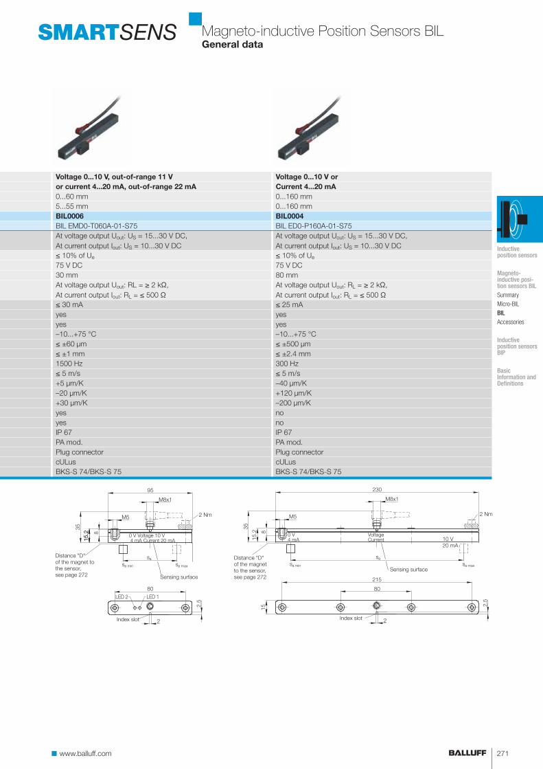
Voltage 0...10 V, out-of-range 11 V Voltage 0...10 V or
or current 4...20 mA, out-of-range 22 mA Current 4...20 mA
0...60 mm 0...160 mm
5...55 mm 0...160 mm
BIL0006 BIL0004
BIL EMD0-T060A-01-S75 BIL ED0-P160A-01-S75
At voltage output Uout: US = 15...30 V DC,
At current output Iout: US = 10...30 V DC
At voltage output Uout: US = 15...30 V DC,
At current output Iout: US = 10...30 V DC
≤ 10% of Ue ≤ 10% of Ue
75 V DC 75 V DC
30 mm 80 mm
At voltage output Uout: RL = ≥ 2 kΩ,
At current output Iout: RL = ≤ 500 Ω
At voltage output Uout: RL = ≥ 2 kΩ,
At current output Iout: RL = ≤ 500 Ω
≤ 30 mA ≤ 25 mA
yes yes
yes yes
–10...+75 °C –10...+75 °C
≤ ±60 μm ≤ ±500 μm
≤ ±1 mm ≤ ±2.4 mm
1500 Hz 300 Hz
≤ 5 m/s ≤ 5 m/s
+5 μm/K –40 μm/K
–20 μm/K +120 μm/K
+30 μm/K –200 μm/K
yes no
yes no
IP 67 IP 67
PA mod. PA mod.
Plug connector Plug connector
cULus cULus
BKS-S 74/BKS-S 75 BKS-S 74/BKS-S 75
SMARTSENS
Sensing surface
Index slot
Distance "D"
of the magnet
to the sensor,
see page 272
10 V
20 mA
0 V Voltage 10 V 4 mA Current 20 mA
Distance "D"
of the magnet to
the sensor,
see page 272 Sensing surface
Index slot
Magneto-inductive Position Sensors BILGeneral data
0 V4 mA
VoltageCurrent
Inductive position sensors
Magneto- inductive posi-tion sensors BILSummary
Micro-BIL
BILAccessories
Inductive position sensors BIP
Basic Information and Definitions
For more information, visit us online!272
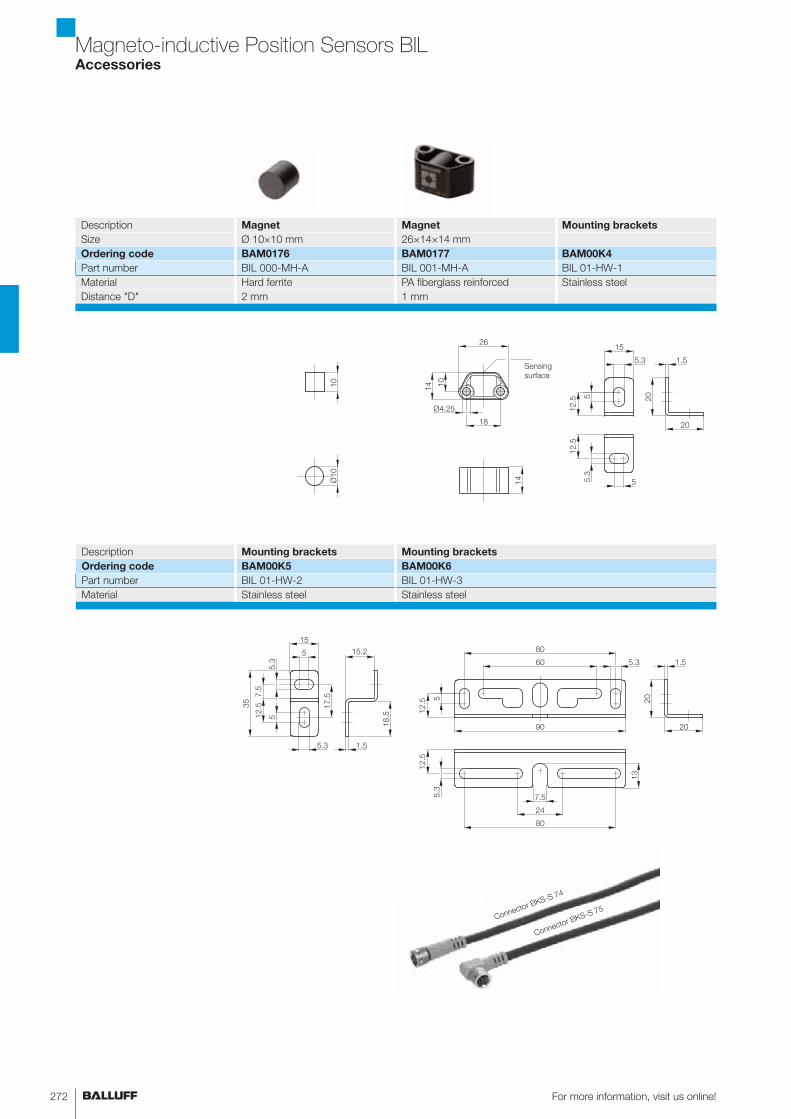
Magneto-inductive Position Sensors BILAccessories
Sensing
surface
Description Magnet Magnet Mounting brackets
Size Ø 10×10 mm 26×14×14 mm
Ordering code BAM0176 BAM0177 BAM00K4
Part number BIL 000-MH-A BIL 001-MH-A BIL 01-HW-1
Material Hard ferrite PA fiberglass reinforced Stainless steel
Distance "D" 2 mm 1 mm
Description Mounting brackets Mounting brackets
Ordering code BAM00K5 BAM00K6
Part number BIL 01-HW-2 BIL 01-HW-3
Material Stainless steel Stainless steel
Connector BKS-S 74
Connector BKS-S 75
273www.balluff.com
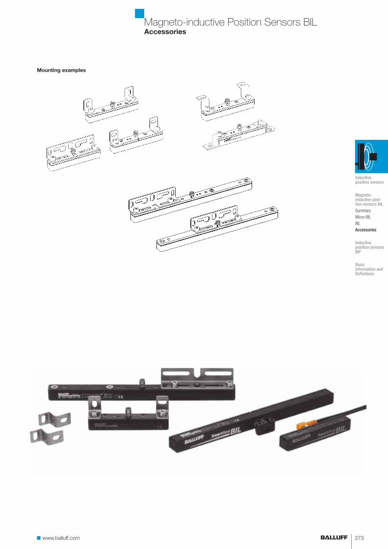
Mounting examples
Magneto-inductive Position Sensors BILAccessories
Inductive position sensors
Magneto- inductive posi-tion sensors BILSummary
Micro-BIL
BIL
Accessories
Inductive position sensors BIP
Basic Information and Definitions
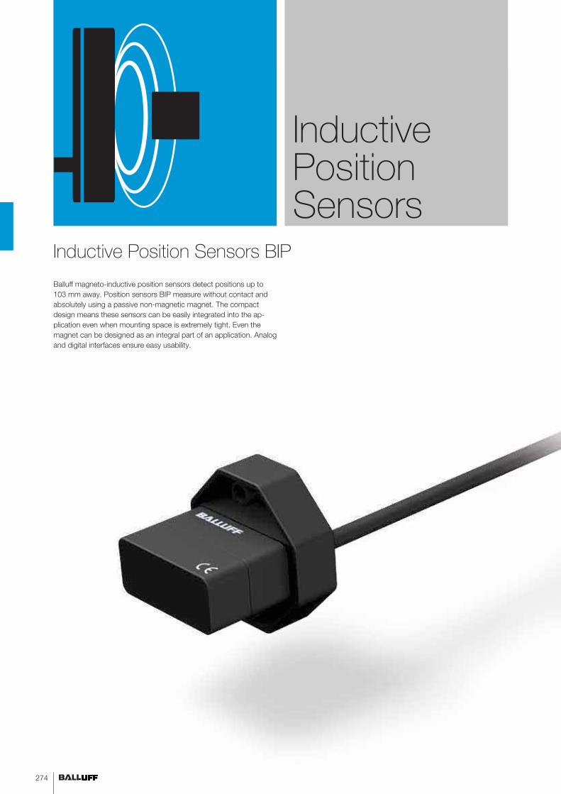
Balluff magneto-inductive position sensors detect positions up to
103 mm away. Position sensors BIP measure without contact and
absolutely using a passive non-magnetic magnet. The compact
design means these sensors can be easily integrated into the ap-
plication even when mounting space is extremely tight. Even the
magnet can be designed as an integral part of an application. Analog
and digital interfaces ensure easy usability.
Inductive Position Sensors
Inductive Position Sensors BIP
274
275www.balluff.com 275www.balluff.com
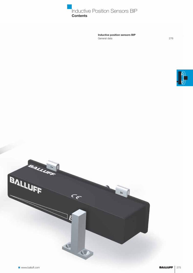
Inductive Position Sensors BIPContents
Inductive position sensors BIP
General data 276
For more information, visit us online!276
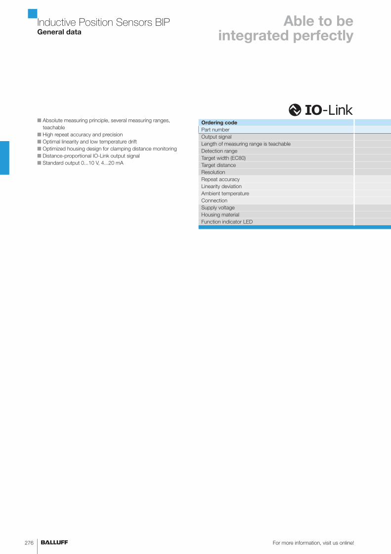
Inductive Position Sensors BIPGeneral data
Able to be integrated perfectly
Ordering code
Part number
Output signal
Length of measuring range is teachable
Detection range
Target width (EC80)
Target distance
Resolution
Repeat accuracy
Linearity deviation
Ambient temperature
Connection
Supply voltage
Housing material
Function indicator LED
■ Absolute measuring principle, several measuring ranges,
teachable
■ High repeat accuracy and precision
■ Optimal linearity and low temperature drift
■ Optimized housing design for clamping distance monitoring
■ Distance-proportional IO-Link output signal
■ Standard output 0...10 V, 4...20 mA

277www.balluff.com
Inductive Position Sensors BIPGeneral data
BIP0001 BIP0007 BIP0008 BIP0002 BIP0004 BIP0005
BIP AD0-B014-01-EP02 BIP LD2-T014-01-EP02 BIP CD2-B014-01-EP02 BIP AD2-B040-02-S4 BIP LD2-T040-02-S4 BIP CD2-B040-02-S4
0...10 V IO-Link 4...20 mA 0...10 V IO-Link 4...20 mA
7...14 mm 20...40 mm
0...14 mm 0...40 mm
8 mm 14 mm
0.5...2 mm 1...3 mm
14 μm 40 μm
±80 μm ±100 μm
±250 μm ±400 μm
–25...+70°C –25...+85°C
2 m cable M12 connector
15...30 V (IO-Link 18...30 V) 15...30 V (IO-Link 18...30 V)
PA PA
yes yes
Inductive position sensors
Magneto- inductive posi-tion sensors BIL
Inductive position sensors BIPGeneral data
Basic Information and Definitions
For more information, visit us online!278
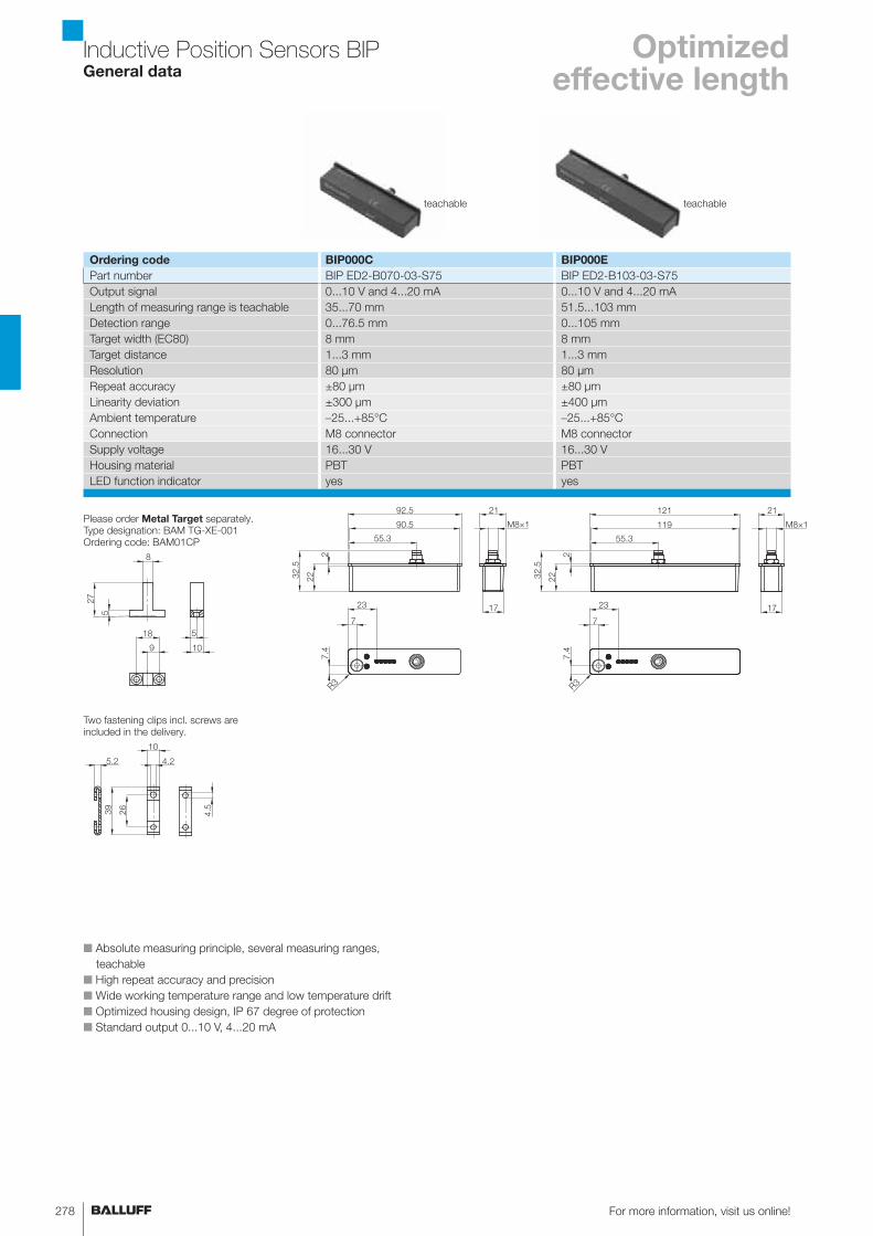
Inductive Position Sensors BIPGeneral data
Optimized effective length
■ Absolute measuring principle, several measuring ranges,
teachable
■ High repeat accuracy and precision
■ Wide working temperature range and low temperature drift
■ Optimized housing design, IP 67 degree of protection
■ Standard output 0...10 V, 4...20 mA
Ordering code BIP000C BIP000E
Part number BIP ED2-B070-03-S75 BIP ED2-B103-03-S75
Output signal 0...10 V and 4...20 mA 0...10 V and 4...20 mA
Length of measuring range is teachable 35...70 mm 51.5...103 mm
Detection range 0...76.5 mm 0...105 mm
Target width (EC80) 8 mm 8 mm
Target distance 1...3 mm 1...3 mm
Resolution 80 μm 80 μm
Repeat accuracy ±80 μm ±80 μm
Linearity deviation ±300 μm ±400 μm
Ambient temperature –25...+85°C –25...+85°C
Connection M8 connector M8 connector
Supply voltage 16...30 V 16...30 V
Housing material PBT PBT
LED function indicator yes yes
R3
2
2232.5
7
55.3
119
121
23
7.4
M8×1
21
17
R3
2
2232.5
7
55.3
90.5
92.5
23
7.4
M8×1
21
17
teachable teachable
5
27
8
18
109
5
26
4.2
39
10
5.2
4.5
Please order Metal Target separately.
Type designation: BAM TG-XE-001
Ordering code: BAM01CP
Two fastening clips incl. screws are
included in the delivery.
279www.balluff.com
Inductive Position Sensors BIPApplication
Inductive position sensors
Magneto- inductive posi-tion sensors BIL
Inductive position sensors BIPGeneral data
Basic Information and Definitions
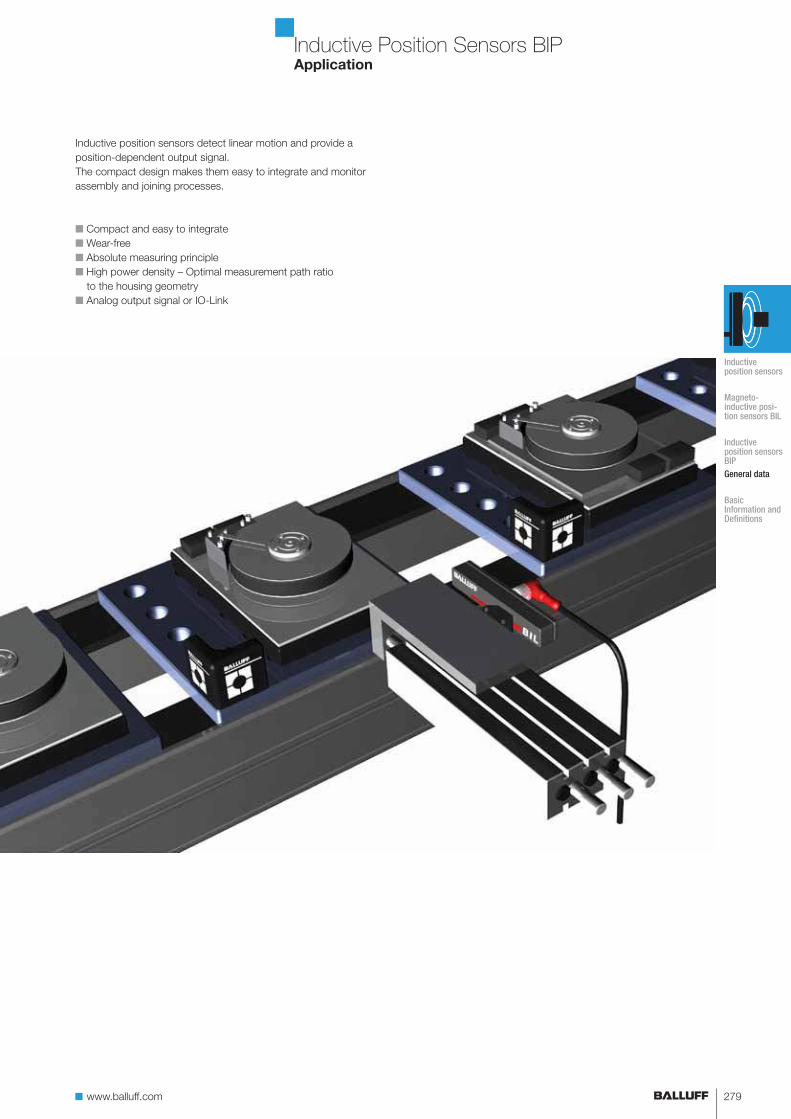
Inductive position sensors detect linear motion and provide a
position-dependent output signal.
The compact design makes them easy to integrate and monitor
assembly and joining processes.
■ Compact and easy to integrate
■ Wear-free
■ Absolute measuring principle
■ High power density – Optimal measurement path ratio
to the housing geometry
■ Analog output signal or IO-Link
Inductive Position Sensors
280
www.balluff.com
Basic Information and DefinitionsContents
Basic information and definitions
Definitions 282
www.balluff.com 281
For more information, visit us online!282
Basic Information and DefinitionsDefinitions
Position sensors
with analog output
Working range sw
Effective distance se
Linear range sI
Non-linearity
Measuring speed
Response time
Slope
Temperature drift
Temperature coefficient TC
Tolerance T
Position sensors with analog output are sensors that generate a con-
tinually varying output signal that depends on the distance between its
sensing surface and the location of the magnet relative to the sensor.
Working range sw is the travel path usable for position detection.
Effective distance se is the point in the middle of the linear range sI
and is used as the reference point for other specifications.
Linear range sI corresponds to the working range where the displace-
ment sensor exhibits a defined linearity.
Non-linearity specifies the maximum deviation of the characteristic
from a straight reference line. This value applies to the linear range.
Measurement speed indicates the ability to detect the position of an
object moving with linear motion. The direction of movement of the
object is assumed to be parallel to its sensing face.
Response time is the time a sensor requires to reliably and steadily
change the output signal. The specified time, which has been deter-
mined at the maximum measuring speed, includes both the electrical
response time of the sensor and the time for the mechanical change
of the damping state.
Slope is a measure of the sensitivity of the sensor with respect to a
distance change. This physical relationship can be calculated for posi-
tion sensors as follows:
Slope S [V/mm] =Uout max – Uout min
sw max – sw min
or
Slope S [mA/mm] = Iout max – Iout min
sw max – sw min
Temperature drift is the shift a point experiences on the actual output
curve at different temperatures. Temperature drift is described by the
temperature coefficient.
Temperature coefficient TC describes the deviation of the sensor
output signal under the effect of a temperature change, and thus
represents a quality criterion for the sensor as well.
Tolerance T is a variable that defines the manufacturing tolerance
band of the output curve, thereby determining the maximum sample
deviation.
283www.balluff.com
Basic Information and DefinitionsDefinitions
Repeat accuracy R
Repeat accuracy RBWN
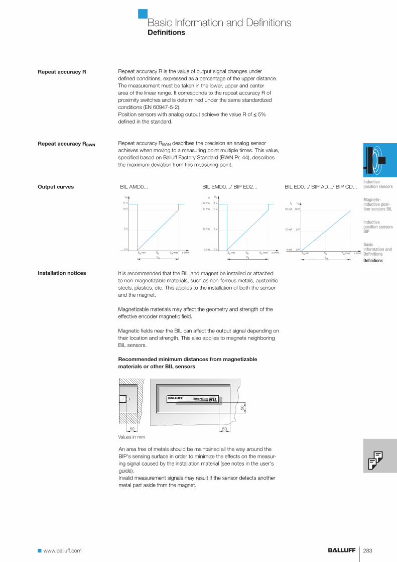
Output curves
Installation notices
Values in mm
Recommended minimum distances from magnetizable
materials or other BIL sensors
BIL AMD0... BIL EMD0.../ BIP ED2... BIL ED0.../ BIP AD.../ BIP CD...
Repeat accuracy R is the value of output signal changes under
defined conditions, expressed as a percentage of the upper distance.
The measurement must be taken in the lower, upper and center
area of the linear range. It corresponds to the repeat accuracy R of
proximity switches and is determined under the same standardized
conditions (EN 60947-5-2).
Position sensors with analog output achieve the value R of ≤ 5%
defined in the standard.
Repeat accuracy RBWN describes the precision an analog sensor
achieves when moving to a measuring point multiple times. This value,
specified based on Balluff Factory Standard (BWN Pr. 44), describes
the maximum deviation from this measuring point.
It is recommended that the BIL and magnet be installed or attached
to non-magnetizable materials, such as non-ferrous metals, austenitic
steels, plastics, etc. This applies to the installation of both the sensor
and the magnet.
Magnetizable materials may affect the geometry and strength of the
effective encoder magnetic field.
Magnetic fields near the BIL can affect the output signal depending on
their location and strength. This also applies to magnets neighboring
BIL sensors.
An area free of metals should be maintained all the way around the
BIP's sensing surface in order to minimize the effects on the measur-
ing signal caused by the installation material (see notes in the user's
guide).
Invalid measurement signals may result if the sensor detects another
metal part aside from the magnet.
Inductive position sensors
Magneto- inductive posi-tion sensors BIL
Inductive position sensors BIP
Basic Information and DefinitionsDefinitions
Related Documents