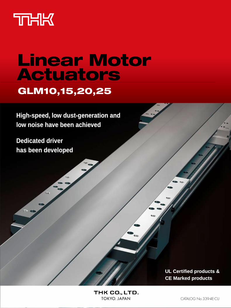
High-speed, low dust-generation and low noise have been achieved Dedicated driver has been developed UL Certified products & CE Marked products GLM10,15,20,25 Linear Motor Actuators CATALOG No.339-4E-CU High-speed, low dust-generation and low noise have been achieved Dedicated driver has been developed UL Certified products & CE Marked products

Welcome message from author
This document is posted to help you gain knowledge. Please leave a comment to let me know what you think about it! Share it to your friends and learn new things together.
Transcript
All rights reserved
“LM GUIDE,” “Caged Ball,” and “ ” are registered trademarks of THK CO., LTD. The actual products may differ from the pictures and photographs in this catalog. Outward appearances and specifications is subject to change without notification for purposes of improvement, please inquire before using them. Although great care has been taken in the production of this catalog, THK will not take any responsibility for damage resulting from typographical errors or omissions. In exporting our products and technology, or selling them for the purpose of export, THK has a basic policy of observing laws relating to foreign exchange,
trade and other laws. For export of THK products as single items, contact THK in advance.
Linear Motor Actuators GLM10,15,20,25
Precautions on Use Environment
The wrong environment can cause failure for the actuator and driver. The best places to use the device are as follows:• For actuators, an environment with a room and ambient temperature from 0 to 40 °C and humidity of no more than 80% RH that will not expose the
product to freezing or condensation.• For drivers, an environment with a room and ambient temperature from 0 to 50 °C and humidity of no more than 90% RH that will not expose the
product to freezing or condensation.• A place free from corrosive gas or flammable gas.• Places where none of the following are flying around: iron particles, or any other conductive particles, dust, oil mist, cutting fluid, water, salt,
organic solvents.• Places that are not exposed to direct sunlight or radiant heat.• Places where no strong electric fields or strong magnetic fields occur.• Places where vibration or impact are not transmitted to the unit.• Places that are easy to inspect and clean.
Safety Precautions• Do not drop or knock this product. Doing so may cause injury or damage the unit.• Unnecessarily disassembling this product may allow foreign objects to enter and reduce functionality. Also, there is a risk of electric shock from
the driver.• The PL seal is attached to the end plate of the unit body. If the user has selected a unit option without an end plate, no PL seal will be attached.
Therefore, the user must prepare his own PL seal.• The magnet plate (stator) is a very powerful magnet. Keep magnetic bodies (particularly metals) away from the magnet plate. There is a risk of
getting the finger(s) jammed between the metal body and the magnet due to the attractive force of the magnet. Also, persons using cardiac pacemakers should absolutely stay away from the magnet.
• Never touch the moving section of the actuator when it is energized. Also, when the product is in motion, or in a state of readiness for motion, do not enter the movement zone of the actuator.
• When carrying out installation, adjustment, inspection or maintenance of the actuator unit, driver or connected associated devices, always remove all plugs from the power sockets, and use locking or safety plugs etc. so that no one but an operator can turn on the power again. Also, display a notice explaining what work is in progress in a position that is readily seen.
• If two or more people are involved in the operation, confirm the procedures such as sequences, signs, and abnormalities in advance, and appoint another person for monitoring the operation.
• Read the manual carefully, understanding the content properly, and be sure to observe all safety precautions.
HEAD OFFICE 3-11-6, NISHI-GOTANDA, SHINAGAWA-KU, TOKYO 141-8503 JAPAN INTERNATIONAL SALES DEPARTMENT PHONE:+81-3-5434-0351 FAX:+81-3-5434-0353
Global site : http://www.thk.com/
TAIWANTHK TAIWAN CO.,LTD.
TAIPEI HEAD OFFICEPhone:+886-2-2888-3818TAICHUNG OFFICEPhone:+886-4-2359-1505 TAINAN OFFICEPhone:+886-6-289-7668
KOREASEOUL REPRESENTATIVE OFFICE
Phone:+82-2-3468-4351SINGAPORETHK LM SYSTEM Pte. Ltd.
NORTH AMERICATHK America,Inc.
HEADQUARTERSPhone:+1-847-310-1111 Fax:+1-847-310-1271CHICAGO OFFICEPhone:+1-847-310-1111 Fax:+1-847-310-1182NORTH EAST OFFICE Phone:+1-845-369-4035 Fax:+1-845-369-4909ATLANTA OFFICEPhone:+1-770-840-7990 Fax:+1-770-840-7897LOS ANGELES OFFICEPhone:+1-949-955-3145 Fax:+1-949-955-3149SAN FRANCISCO OFFICEPhone:+1-925-455-8948 Fax:+1-925-455-8965DETROIT OFFICEPhone:+1-248-858-9330 Fax:+1-248-858-9455TORONTO OFFICEPhone:+1-905-820-7800 Fax:+1-905-820-7811
SOUTH AMERICATHK Brasil LTDA
Phone:+55-11-3767-0100 Fax:+55-11-3767-0101EUROPETHK GmbH
DÜSSELDORF OFFICEPhone:+49-2102-7425-0 Fax:+49-2102-7425-299
EUROPEAN HEADQUARTERSPhone:+49-2102-7425-0 Fax:+49-2102-7425-217
SHANGHAI OFFICEPhone:+86-21-6219-3000 Fax:+86-21-6219-9890BEIJING OFFICEPhone:+86-10-8441-7277 Fax:+86-10-6590-3557CHENGDU OFFICEPhone:+86-28-8526-8025 Fax:+86-28-8525-6357GUANGZHOU OFFICEPhone:+86-20-8523-8418 Fax:+86-20-3801-0456
CHINATHK (CHINA) CO.,LTD.
TURKEY OFFICEPhone:+90-216-362-4050 Fax:+90-216-569-7150PRAGUE OFFICEPhone:+420-2-41025-100 Fax:+420-2-41025-199
FRANKFURT OFFICEPhone:+49-2102-7425-650 Fax:+49-2102-7425-699STUTTGART OFFICEPhone:+49-7150-9199-0 Fax:+49-7150-9199-888MÜNCHEN OFFICEPhone:+49-8937-0616-0 Fax:+49-8937-0616-26U.K. OFFICEPhone:+44-1908-30-3050 Fax:+44-1908-30-3070ITALY MILANO OFFICEPhone:+39-039-284-2079 Fax:+39-039-284-2527ITALY BOLOGNA OFFICEPhone:+39-051-641-2211 Fax:+39-051-641-2230SWEDEN OFFICEPhone:+46-8-445-7630 Fax:+46-8-445-7639 AUSTRIA OFFICEPhone:+43-7229-51400 Fax:+43-7229-51400-79SPAIN OFFICEPhone:+34-93-652-5740 Fax:+34-93-652-5746
EINDHOVEN OFFICETHK Europe B.V.
THK France S.A.S.Phone:+33-4-3749-1400
Phone:+31-040-290-9500 Fax:+31-040-290-9599
Fax:+33-4-3749-1401
HEADQUARTERSPhone:+86-411-8733-7111 Fax:+86-411-8733-7000
THK (SHANGHAI) CO.,LTD.Phone:+86-21-6275-5280 Fax:+86-21-6219-9890
Fax:+886-2-2888-3819
Fax:+886-4-2359-1506
Fax:+886-6-289-7669
Fax:+82-2-3468-4353
Fax:+65-6884-5550INDIABANGALORE REPRESENTATIVE OFFICE
Phone:+91-80-2330-1524
Phone:+65-6884-5500
Fax:+91-80-2314-8226
©THK CO., LTD. 200903003 E8 Printed in Japan
High-speed, low dust-generation and low noise have been achieved
Dedicated driver has been developed
UL Certified products & CE Marked products
GLM10,15,20,25
Linear MotorActuators
CATALOG No.339-4E-CU
Lin
ea
r M
oto
r A
ctu
ato
rs
GL
M10
, 15
, 20
, 25
UL
Ce
rtified
pro
du
cts
& C
E M
ark
ed
pro
du
cts
High-speed, low dust-generation and low noise have been achieved
Dedicated driver has been developed
UL Certified products & CE Marked products
UL
Ce
rtified
pro
du
cts
& C
E M
ark
ed
pro
du
cts
11 221
L i n e a r M o t o r A c t uL i n e a r M o t o r A c t u a t o ra t o r s
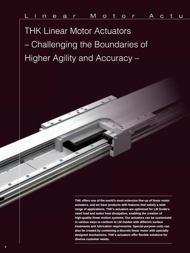
THK Linear Motor ActuatorsTHK Linear Motor Actuators
– Challenging the Boundaries of – Challenging the Boundaries of
Higher Agility and Accuracy –Higher Agility and Accuracy –
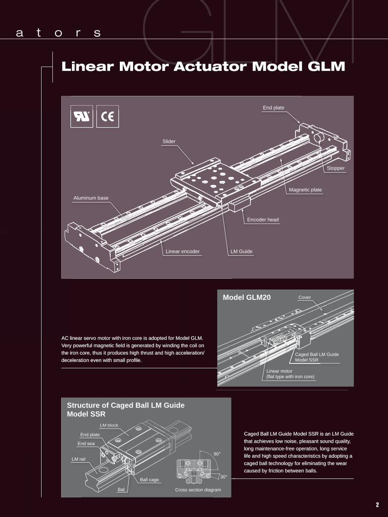
Linear Motor Actuator Model GLMLinear Motor Actuator Model GLM
Caged Ball LM Guide Model SSR is an LM GuideCaged Ball LM Guide Model SSR is an LM Guide
that achieves low noise, pleasant sound quality, that achieves low noise, pleasant sound quality,
long maintenance-free operation, long service long maintenance-free operation, long service
life and high speed characteristics by adopting a life and high speed characteristics by adopting a
caged ball technology for eliminating the wear caged ball technology for eliminating the wear
caused by friction between balls.caused by friction between balls.
AC linear servo motor with iron core is adopted for Model GLM. AC linear servo motor with iron core is adopted for Model GLM.
Very powerful magnetic field is generated by winding the coil on Very powerful magnetic field is generated by winding the coil on
the iron core, thus it produces high thrust and high acceleration/the iron core, thus it produces high thrust and high acceleration/
deceleration even with small profile. deceleration even with small profile.
THK offers one of the world's most extensive line-up of linear motor THK offers one of the world's most extensive line-up of linear motor actuators, and we have products with features that satisfy a wide actuators, and we have products with features that satisfy a wide range of applications. THK's actuators are optimized for LM Guide's range of applications. THK's actuators are optimized for LM Guide's rated load and motor heat dissipation, enabling the creation of rated load and motor heat dissipation, enabling the creation of high-quality linear motion systems. Our actuators can be customized high-quality linear motion systems. Our actuators can be customized in various ways to conform to LM Guides with different surface in various ways to conform to LM Guides with different surface treatments and lubrication requirements. Special-purpose units can treatments and lubrication requirements. Special-purpose units can also be created by combining a discrete linear motor with specially also be created by combining a discrete linear motor with specially designed mechanisms. THK's actuators offer flexible solutions for designed mechanisms. THK's actuators offer flexible solutions for diverse customer needs.diverse customer needs.
L i n e a r M o t o r A c t u a t o r s
Linear Motor Actuator Model GLMTHK Linear Motor Actuators
– Challenging the Boundaries of
Higher Agility and Accuracy –
Model GLM20
Caged Ball LM Guide Model SSR is an LM Guide
that achieves low noise, pleasant sound quality,
long maintenance-free operation, long service
life and high speed characteristics by adopting a
caged ball technology for eliminating the wear
caused by friction between balls.
AC linear servo motor with iron core is adopted for Model GLM.
Very powerful magnetic field is generated by winding the coil on
the iron core, thus it produces high thrust and high acceleration/
deceleration even with small profile.
Structure of Caged Ball LM Guide Model SSR
Cover
Linear motor(flat type with iron core)
Caged Ball LM Guide Model SSR
Slider
Stopper
Magnetic plate
Encoder head
LM GuideLinear encoder
End plate
Aluminum base
Cross section diagram
90°
30°
LM block
LM rail
End plate
End seal
Ball cage
Ball
THK offers one of the world's most extensive line-up of linear motor actuators, and we have products with features that satisfy a wide range of applications. THK's actuators are optimized for LM Guide's rated load and motor heat dissipation, enabling the creation of high-quality linear motion systems. Our actuators can be customized in various ways to conform to LM Guides with different surface treatments and lubrication requirements. Special-purpose units can also be created by combining a discrete linear motor with specially designed mechanisms. THK's actuators offer flexible solutions for diverse customer needs.
LM block
LM rail
End plate
End seal
Ball cage
Ball
11 221
L i n e a r M o t o r A c t uL i n e a r M o t o r A c t u a t o ra t o r s
THK Linear Motor ActuatorsTHK Linear Motor Actuators
– Challenging the Boundaries of – Challenging the Boundaries of
Higher Agility and Accuracy –Higher Agility and Accuracy –
Linear Motor Actuator Model GLMLinear Motor Actuator Model GLM
Caged Ball LM Guide Model SSR is an LM GuideCaged Ball LM Guide Model SSR is an LM Guide
that achieves low noise, pleasant sound quality, that achieves low noise, pleasant sound quality,
long maintenance-free operation, long service long maintenance-free operation, long service
life and high speed characteristics by adopting a life and high speed characteristics by adopting a
caged ball technology for eliminating the wear caged ball technology for eliminating the wear
caused by friction between balls.caused by friction between balls.
AC linear servo motor with iron core is adopted for Model GLM. AC linear servo motor with iron core is adopted for Model GLM.
Very powerful magnetic field is generated by winding the coil on Very powerful magnetic field is generated by winding the coil on
the iron core, thus it produces high thrust and high acceleration/the iron core, thus it produces high thrust and high acceleration/
deceleration even with small profile. deceleration even with small profile.
THK offers one of the world's most extensive line-up of linear motor THK offers one of the world's most extensive line-up of linear motor actuators, and we have products with features that satisfy a wide actuators, and we have products with features that satisfy a wide range of applications. THK's actuators are optimized for LM Guide's range of applications. THK's actuators are optimized for LM Guide's rated load and motor heat dissipation, enabling the creation of rated load and motor heat dissipation, enabling the creation of high-quality linear motion systems. Our actuators can be customized high-quality linear motion systems. Our actuators can be customized in various ways to conform to LM Guides with different surface in various ways to conform to LM Guides with different surface treatments and lubrication requirements. Special-purpose units can treatments and lubrication requirements. Special-purpose units can also be created by combining a discrete linear motor with specially also be created by combining a discrete linear motor with specially designed mechanisms. THK's actuators offer flexible solutions for designed mechanisms. THK's actuators offer flexible solutions for diverse customer needs.diverse customer needs.
L i n e a r M o t o r A c t u a t o r s
Linear Motor Actuator Model GLMTHK Linear Motor Actuators
– Challenging the Boundaries of
Higher Agility and Accuracy –
Model GLM20
Caged Ball LM Guide Model SSR is an LM Guide
that achieves low noise, pleasant sound quality,
long maintenance-free operation, long service
life and high speed characteristics by adopting a
caged ball technology for eliminating the wear
caused by friction between balls.
AC linear servo motor with iron core is adopted for Model GLM.
Very powerful magnetic field is generated by winding the coil on
the iron core, thus it produces high thrust and high acceleration/
deceleration even with small profile.
Structure of Caged Ball LM Guide Model SSR
Cover
Linear motor(flat type with iron core)
Caged Ball LM Guide Model SSR
Slider
Stopper
Magnetic plate
Encoder head
LM GuideLinear encoder
End plate
Aluminum base
Cross section diagram
90°
30°
LM block
LM rail
End plate
End seal
Ball cage
Ball
THK offers one of the world's most extensive line-up of linear motor actuators, and we have products with features that satisfy a wide range of applications. THK's actuators are optimized for LM Guide's rated load and motor heat dissipation, enabling the creation of high-quality linear motion systems. Our actuators can be customized in various ways to conform to LM Guides with different surface treatments and lubrication requirements. Special-purpose units can also be created by combining a discrete linear motor with specially designed mechanisms. THK's actuators offer flexible solutions for diverse customer needs.
LM block
LM rail
End plate
End seal
Ball cage
Ball
333
GLGLM
GLGLM
GLGLM
GLGLM
1
2
3
6
4
5
Linear Motor Actuator Model GLMLinear Motor Actuator Model GLM
FeaturesFeatures
High speedHigh speed
High acceleration/High acceleration/deceleration, deceleration,
superb conformitysuperb conformity
High precisionHigh precision
Clean and quiet Clean and quiet operationoperation
Long strokeLong stroke
Multi-slidersMulti-sliders
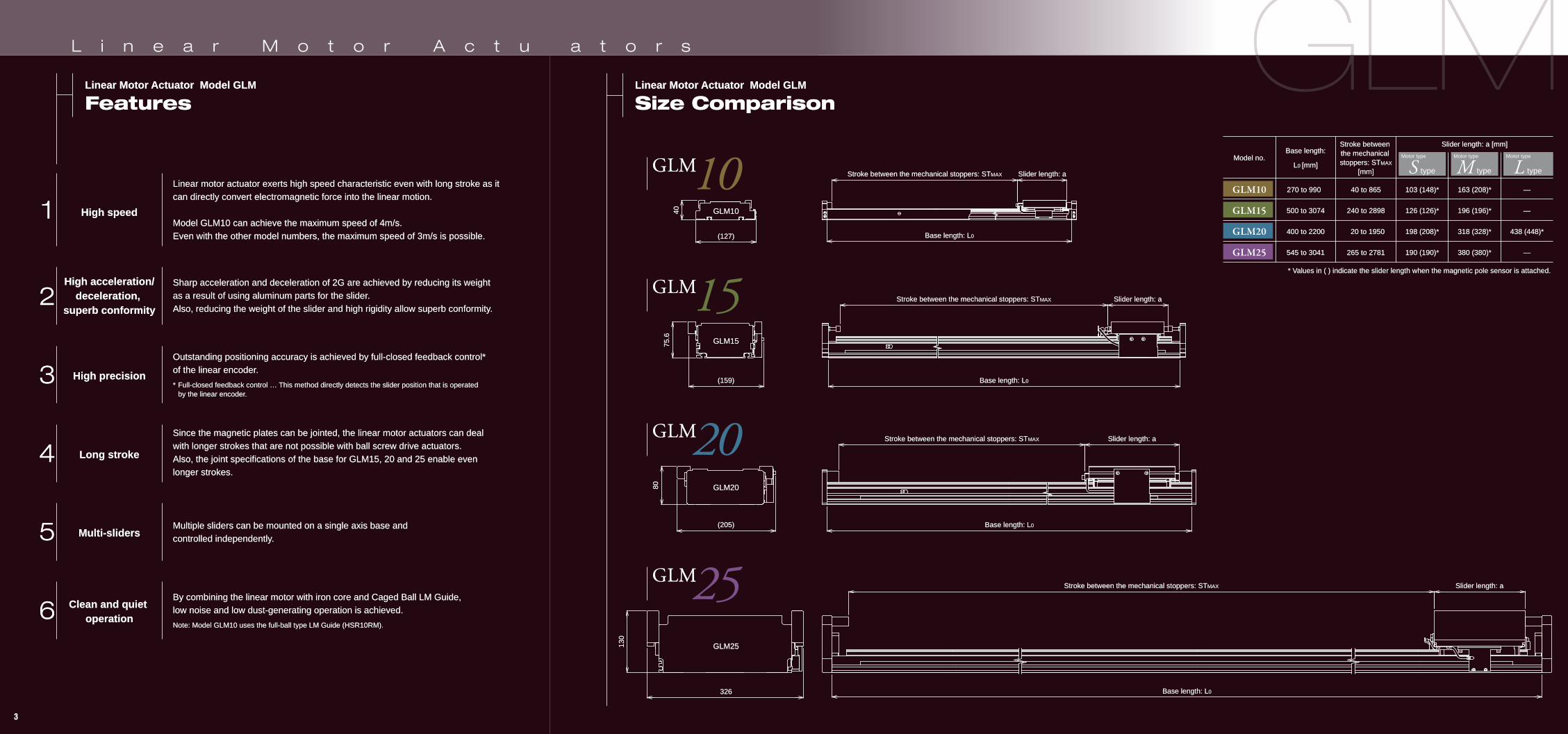
Linear motor actuator exerts high speed characteristic even with long stroke as it Linear motor actuator exerts high speed characteristic even with long stroke as it can directly convert electromagnetic force into the linear motion.can directly convert electromagnetic force into the linear motion.
Model GLM10 can achieve the maximum speed of 4m/s.Model GLM10 can achieve the maximum speed of 4m/s.Even with the other model numbers, the maximum speed of 3m/s is possible. Even with the other model numbers, the maximum speed of 3m/s is possible.
Sharp acceleration and deceleration of 2G are achieved by reducing its weight Sharp acceleration and deceleration of 2G are achieved by reducing its weight as a result of using aluminum parts for the slider.as a result of using aluminum parts for the slider.Also, reducing the weight of the slider and high rigidity allow superb conformity. Also, reducing the weight of the slider and high rigidity allow superb conformity.
Since the magnetic plates can be jointed, the linear motor actuators can deal Since the magnetic plates can be jointed, the linear motor actuators can deal with longer strokes that are not possible with ball screw drive actuators. with longer strokes that are not possible with ball screw drive actuators. Also, the joint specifications of the base for GLM15, 20 and 25 enable even Also, the joint specifications of the base for GLM15, 20 and 25 enable even longer strokes. longer strokes.
Multiple sliders can be mounted on a single axis base and Multiple sliders can be mounted on a single axis base and controlled independently.controlled independently.
By combining the linear motor with iron core and Caged Ball LM Guide, By combining the linear motor with iron core and Caged Ball LM Guide, low noise and low dust-generating operation is achieved.low noise and low dust-generating operation is achieved.
Note: Model GLM10 uses the full-ball type LM Guide (HSR10RM). Note: Model GLM10 uses the full-ball type LM Guide (HSR10RM).
Outstanding positioning accuracy is achieved by full-closed feedback control* Outstanding positioning accuracy is achieved by full-closed feedback control* of the linear encoder. of the linear encoder.
* Full-closed feedback control … This method directly detects the slider position that is operated * Full-closed feedback control … This method directly detects the slider position that is operated by the linear encoder. by the linear encoder.
Linear Motor Actuator Model GLMLinear Motor Actuator Model GLM
Size ComparisonSize Comparison
GLM10GLM10
(127)(127)
4040
(159)(159)
75.6
75.6
GLM15GLM15
GLM20GLM20
GLM25GLM25
(205)(205)
8080
326326
130
130
Slider length: aSlider length: aStroke between the mechanical stoppers: STStroke between the mechanical stoppers: STMAXMAX
Base length: LBase length: L0
Slider length: aSlider length: aStroke between the mechanical stoppers: STStroke between the mechanical stoppers: STMAXMAX
Base length: LBase length: L0
Slider length: aSlider length: aStroke between the mechanical stoppers: STStroke between the mechanical stoppers: STMAXMAX
Base length: LBase length: L0
Slider length: aSlider length: aStroke between the mechanical stoppers: STStroke between the mechanical stoppers: STMAXMAX
Base length: LBase length: L0
Model no.Model no.Base length:Base length:
L0 0 [mm][mm]
Stroke between Stroke between the mechanical the mechanical stoppers: STstoppers: STMAXMAX
[mm][mm]
Slider length: a [mm]Slider length: a [mm]
* Values in ( ) indicate the slider length when the magnetic pole sensor is attached. * Values in ( ) indicate the slider length when the magnetic pole sensor is attached.
270 to 990270 to 990
500 to 3074500 to 3074
400 to 2200400 to 2200
545 to 3041545 to 3041
40 to 86540 to 865
240 to 2898240 to 2898
20 to 195020 to 1950
265 to 2781265 to 2781
103 (148)*103 (148)*
126 (126)*126 (126)*
198 (208)*198 (208)*
190 (190)*190 (190)*
163 (208)*163 (208)*
196 (196)*196 (196)*
318 (328)*318 (328)*
380 (380)*380 (380)*
—
—
438 (448)*438 (448)*
—
L i n e a r M o t o r A c t u a t o r s
Linear Motor Actuator Model GLM
Size Comparison
* Values in ( ) indicate the slider length when the magnetic pole sensor is attached.
GLM10
GLM15
GLM20
GLM25
S type M type L type
270 to 990
500 to 3074
400 to 2200
545 to 3041
GLM10
GLM15
GLM20
GLM25
40 to 865
240 to 2898
20 to 1950
265 to 2781
103 (148)*
126 (126)*
198 (208)*
190 (190)*
163 (208)*
196 (196)*
318 (328)*
380 (380)*
—
—
438 (448)*
—
Model no.Base length:
L0 [mm]
Stroke between the mechanical stoppers: STMAX
[mm]
Slider length: a [mm]
Motor type Motor type Motor type
Linear Motor Actuator Model GLM
Features
High speed
High acceleration/deceleration,
superb conformity
High precision
Clean and quiet operation
Long stroke
Multi-sliders
GLM10
GLM20
GLM25
(127)
40
(205)
80
326
130
Slider length: aStroke between the mechanical stoppers: STMAX
Base length: L0
Slider length: aStroke between the mechanical stoppers: STMAX
Base length: L0
Slider length: aStroke between the mechanical stoppers: STMAX
Base length: L0
Slider length: aStroke between the mechanical stoppers: STMAX
Base length: L0
1
2
3
6
4
5
(159)
75.6
GLM15
Linear motor actuator exerts high speed characteristic even with long stroke as it can directly convert electromagnetic force into the linear motion.
Model GLM10 can achieve the maximum speed of 4m/s.Even with the other model numbers, the maximum speed of 3m/s is possible.
Sharp acceleration and deceleration of 2G are achieved by reducing its weight as a result of using aluminum parts for the slider.Also, reducing the weight of the slider and high rigidity allow superb conformity.
Since the magnetic plates can be jointed, the linear motor actuators can deal with longer strokes that are not possible with ball screw drive actuators. Also, the joint specifications of the base for GLM15, 20 and 25 enable even longer strokes.
Multiple sliders can be mounted on a single axis base and controlled independently.
By combining the linear motor with iron core and Caged Ball LM Guide, low noise and low dust-generating operation is achieved.
Note: Model GLM10 uses the full-ball type LM Guide (HSR10RM).
Outstanding positioning accuracy is achieved by full-closed feedback control* of the linear encoder.
* Full-closed feedback control … This method directly detects the slider position that is operated by the linear encoder.
888
12345
Linear Motor Actuator Model GLMLinear Motor Actuator Model GLM
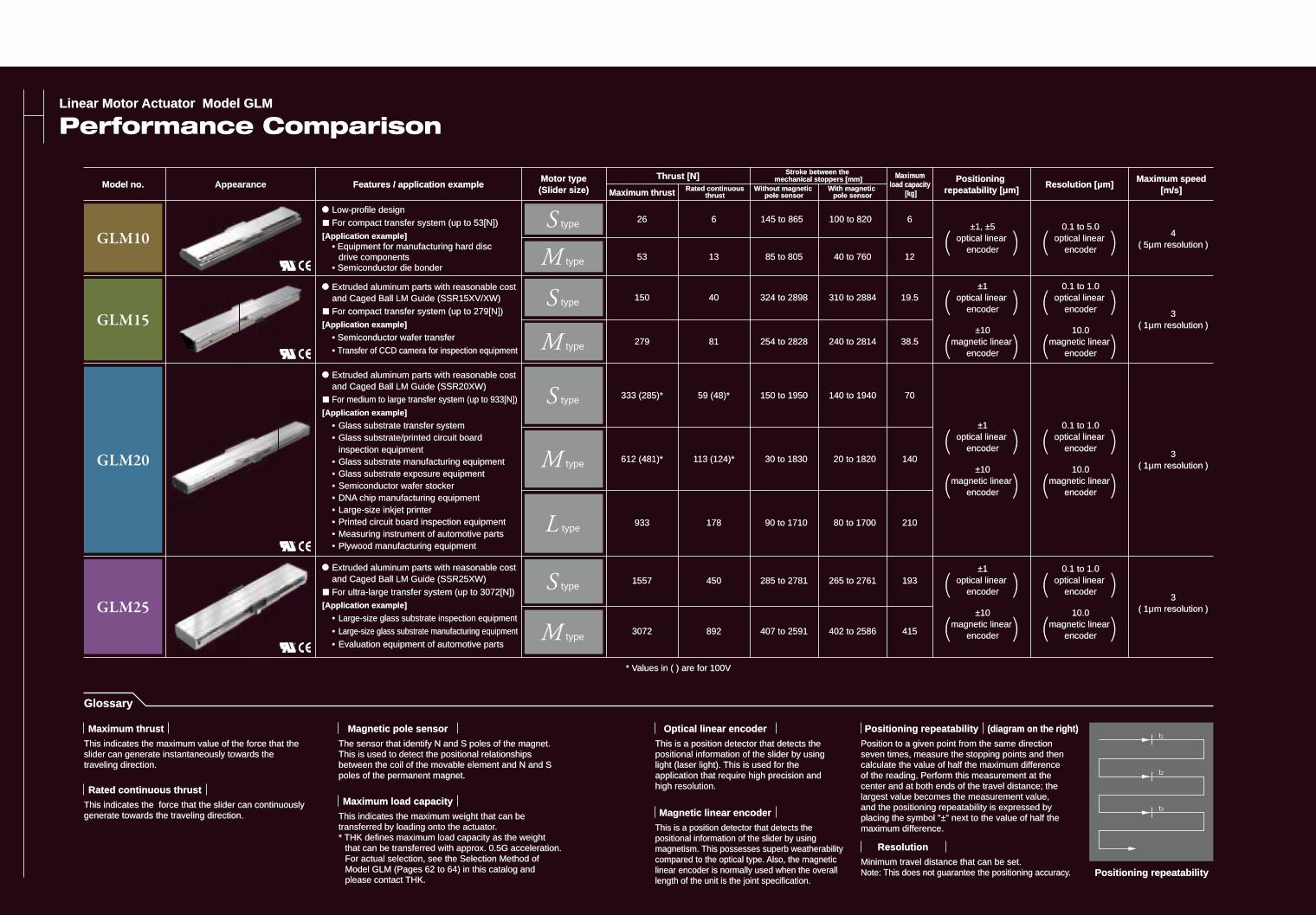
Performance ComparisonPerformance Comparison
AppearanceModel no.Model no. Features / application exampleFeatures / application exampleMotor typeMotor type(Slider size)(Slider size)
Thrust [N]Thrust [N]
Maximum thrustMaximum thrust Without magnetic Without magnetic pole sensorpole sensor
Rated continuousRated continuousthrustthrust
With magnetic With magnetic pole sensorpole sensor
Stroke between the Stroke between the mechanical stoppers [mm]mechanical stoppers [mm]
Resolution [μm]Resolution [μm]Positioning Positioning
repeatability [μm]repeatability [μm]
Maximum Maximum load capacity load capacity
[kg][kg]
2626
5353
150150
279279
333 (285)*333 (285)*
612 (481)*612 (481)*
933933
15571557
30723072
6
1313
4040
8181
59 (48)*59 (48)*
113 (124)*113 (124)*
178178
450450
892892
145 to 865145 to 865
85 to 80585 to 805
324324 to to 28982898
254254 to to 28282828
150150 to to 19501950
3030 to to 18301830
9090 to to 17101710
285285 to to 27812781
407407 to to 25912591
100 to 820100 to 820
40 to 76040 to 760
310310 to to 28842884
240240 to to 28142814
140140 to to 19401940
2020 to to 18201820
8080 to to 17001700
265265 to to 27612761
402402 to to 25862586
6
1212
19.519.5
38.538.5
7070
140140
210210
193193
415415
( )( )±1, ±5±1, ±5
optical linear optical linear encoderencoder
( )( )±1±1
optical linear optical linear encoderencoder
( )( )±10±10
magnetic linear magnetic linear encoderencoder
( )( )0.10.1 to to 5.05.0
optical linear optical linear encoderencoder
( )( )0.1 to 1.00.1 to 1.0
optical linear optical linear encoderencoder
( )( )10.010.0
magnetic linear magnetic linear encoderencoder
4( 5μm resolution5μm resolution )
3( 1μm resolution1μm resolution )
( )( )±1±1
optical linear optical linear encoderencoder
( )( )±10±10
magnetic linear magnetic linear encoderencoder
( )( )0.1 to 1.00.1 to 1.0
optical linear optical linear encoderencoder
( )( )10.010.0
magnetic linear magnetic linear encoderencoder
3( 1μm resolution1μm resolution )
( )( )±1±1
optical linear optical linear encoderencoder
( )( )±10±10
magnetic linear magnetic linear encoderencoder
( )( )0.1 to 1.00.1 to 1.0
optical linear optical linear encoderencoder
( )( )10.010.0
magnetic linear magnetic linear encoderencoder
3( 1μm resolution1μm resolution )
Positioning repeatabilityPositioning repeatability
Position to a given point from the same direction Position to a given point from the same direction seven times, measure the stopping points and then seven times, measure the stopping points and then calculate the value of half the maximum difference calculate the value of half the maximum difference of the reading. Perform this measurement at the of the reading. Perform this measurement at the center and at both ends of the travel distance; the center and at both ends of the travel distance; the largest value becomes the measurement value, largest value becomes the measurement value, and the positioning repeatability is expressed by and the positioning repeatability is expressed by placing the symbol "±" next to the value of half the placing the symbol "±" next to the value of half the maximum difference.maximum difference.
Positioning repeatabilityPositioning repeatability (diagram on the right)(diagram on the right)
Minimum travel distance that can be set. Minimum travel distance that can be set. Note: This does not guarantee the positioning accuracy. Note: This does not guarantee the positioning accuracy.
ResolutionResolution
This is a position detector that detects the This is a position detector that detects the positional information of the slider by using positional information of the slider by using light (laser light). This is used for the light (laser light). This is used for the application that require high precision and application that require high precision and high resolution. high resolution.
Optical linear encoderOptical linear encoder
This is a position detector that detects the This is a position detector that detects the positional information of the slider by using positional information of the slider by using magnetism. This possesses superb weatherability magnetism. This possesses superb weatherability compared to the optical type. Also, the magnetic compared to the optical type. Also, the magnetic linear encoder is normally used when the overall linear encoder is normally used when the overall length of the unit is the joint specification. length of the unit is the joint specification.
Magnetic linear encoderMagnetic linear encoder
* Values in ( ) are for 100V* Values in ( ) are for 100V
The sensor that identify N and S poles of the magnet. The sensor that identify N and S poles of the magnet. This is used to detect the positional relationships This is used to detect the positional relationships between the coil of the movable element and N and S between the coil of the movable element and N and S poles of the permanent magnet.poles of the permanent magnet.
Magnetic pole sensorMagnetic pole sensor
This indicates the maximum weight that can be This indicates the maximum weight that can be transferred by loading onto the actuator. transferred by loading onto the actuator. * THK defines maximum load capacity as the weight * THK defines maximum load capacity as the weight that can be transferred with approx. 0.5G acceleration. that can be transferred with approx. 0.5G acceleration. For actual selection, see the Selection Method of For actual selection, see the Selection Method of Model GLM (Pages 62 to 64) in this catalog and Model GLM (Pages 62 to 64) in this catalog and please contact THK. please contact THK.
Maximum load capacityMaximum load capacity
GlossaryGlossary
This indicates the maximum value of the force that the This indicates the maximum value of the force that the slider can generate instantaneously towards the slider can generate instantaneously towards the traveling direction. traveling direction.
Maximum thrustMaximum thrust
This indicates the force that the slider can continuously This indicates the force that the slider can continuously generate towards the traveling direction. generate towards the traveling direction.
Rated continuous thrustRated continuous thrust
� Low-profile design Low-profile design
� For compact transfer system (up to 53[N]) For compact transfer system (up to 53[N])
[Application example][Application example] • Equipment for manufacturing hard disc • Equipment for manufacturing hard disc drive components drive components • Semiconductor die bonder • Semiconductor die bonder
� Extruded aluminum parts with reasonable cost Extruded aluminum parts with reasonable cost and Caged Ball LM Guide (SSR15XV/XW) and Caged Ball LM Guide (SSR15XV/XW)
� For compact transfer system (up to 279[N]) For compact transfer system (up to 279[N])
[Application example][Application example]
• Semiconductor wafer transfer • Semiconductor wafer transfer
• • Transfer of CCD camera for inspection equipmentTransfer of CCD camera for inspection equipment
� Extruded aluminum parts with reasonable cost Extruded aluminum parts with reasonable cost and Caged Ball LM Guide (SSR25XW) and Caged Ball LM Guide (SSR25XW)
� For ultra-large transfer system (up to 3072[N]) For ultra-large transfer system (up to 3072[N])
[Application example][Application example]
• • Large-size glass substrate inspection equipmentLarge-size glass substrate inspection equipment
• • Large-size glass substrate manufacturing equipmentLarge-size glass substrate manufacturing equipment
• • Evaluation equipment of automotive partsEvaluation equipment of automotive parts
� Extruded aluminum parts with reasonable cost Extruded aluminum parts with reasonable cost and Caged Ball LM Guide (SSR20XW) and Caged Ball LM Guide (SSR20XW)
� For medium to large transfer system (up to 933[N])For medium to large transfer system (up to 933[N])
[Application example][Application example]
• Glass substrate transfer system• Glass substrate transfer system • Glass substrate/printed circuit board • Glass substrate/printed circuit board inspection equipment inspection equipment • Glass substrate manufacturing equipment • Glass substrate manufacturing equipment • Glass substrate exposure equipment • Glass substrate exposure equipment • Semiconductor wafer stocker • Semiconductor wafer stocker • DNA chip manufacturing equipment • DNA chip manufacturing equipment • Large-size inkjet printer • Large-size inkjet printer • Printed circuit board inspection equipment • Printed circuit board inspection equipment • Measuring instrument of automotive parts • Measuring instrument of automotive parts • Plywood manufacturing equipment • Plywood manufacturing equipment
Maximum speed Maximum speed [m/s] [m/s]
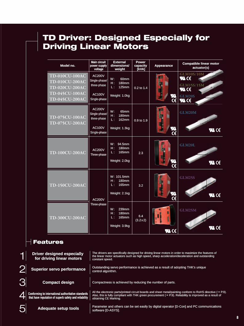
Driver designed especially Driver designed especially for driving linear motorsfor driving linear motors
The drivers are specifically designed for driving linear motors in order to maximize the features of The drivers are specifically designed for driving linear motors in order to maximize the features of the linear motor actuators such as high speed, sharp acceleration/deceleration and outstanding the linear motor actuators such as high speed, sharp acceleration/deceleration and outstanding constant speed. constant speed.
Superior servo performanceSuperior servo performance Outstanding servo performance is achieved as a result of adopting THK's unique Outstanding servo performance is achieved as a result of adopting THK's unique control algorithm. control algorithm.
Compact designCompact design Compactness is achieved by reducing the number of parts. Compactness is achieved by reducing the number of parts.
Conforming to international authoritative standards Conforming to international authoritative standards that have reputation of superb safety and reliabilitythat have reputation of superb safety and reliability
All the electronic parts/printed circuit boards and sheet metal/painting conform to RoHS directive (All the electronic parts/printed circuit boards and sheet metal/painting conform to RoHS directive (� P.9). P.9). Also, this is fully compliant with THK green procurement (Also, this is fully compliant with THK green procurement (� P.9). Reliability is improved as a result of P.9). Reliability is improved as a result of obtaining CE Marking. obtaining CE Marking.
Adequate setup toolsAdequate setup tools Parameter and others can be set easily by digital operator [D-Con] and PC communications Parameter and others can be set easily by digital operator [D-Con] and PC communications software [D-ASYS]. software [D-ASYS].
FeaturesFeatures
TD Driver: Designed Especially for TD Driver: Designed Especially for Driving Linear MotorsDriving Linear Motors
Model no.Model no. AppearanceAppearanceMain circuit Main circuit
power supply power supply voltagevoltage
External External dimensions/dimensions/
weightweight
Power Power capacity capacity
[kVA][kVA]
Compatible linear motoractuator(s)
AC200VAC200V
Single-phase/Single-phase/
three-phasethree-phase
AC100VAC100V
Single-phaseSingle-phase
AC200VAC200V
Single-phase/Single-phase/
three-phasethree-phase
AC100VAC100V
Single-phaseSingle-phase
W : 60mm W : 60mm H : 180mm H : 180mm L : 125mm L : 125mm
Weight: 1.0kgWeight: 1.0kg
W : 65mm W : 65mm H : 180mm H : 180mm L : 162mm L : 162mm
Weight: 1.3kgWeight: 1.3kg
0.2 to 1.40.2 to 1.4
0.9 to 1.90.9 to 1.9
2.32.3
3.23.2
6.46.4(3.2(3.2x2)2)
AC200VAC200V
Three-phaseThree-phase
AC200VAC200V
Three-phaseThree-phase
W : 94.5mm W : 94.5mm H : 180mm H : 180mm L : 165mm L : 165mm
Weight: 2.0kgWeight: 2.0kg
W : 101.5mm W : 101.5mm H : 180mm H : 180mm L : 165mm L : 165mm
Weight: 2.1kgWeight: 2.1kg
W : 239mm W : 239mm H : 180mm H : 180mm L : 165mm L : 165mm
Weight: 3.9kgWeight: 3.9kg
Linear Motor Actuator Model GLM
Performance Comparison
Appearanceble linear motorctuator(s)
� Low-profile design
� For compact transfer system (up to 53[N])
[Application example] • Equipment for manufacturing hard disc drive components • Semiconductor die bonder
� Extruded aluminum parts with reasonable cost and Caged Ball LM Guide (SSR15XV/XW)
� For compact transfer system (up to 279[N])
[Application example]
• Semiconductor wafer transfer
• Transfer of CCD camera for inspection equipment
� Extruded aluminum parts with reasonable cost and Caged Ball LM Guide (SSR25XW)
� For ultra-large transfer system (up to 3072[N])
[Application example]
• Large-size glass substrate inspection equipment
• Large-size glass substrate manufacturing equipment
• Evaluation equipment of automotive parts
� Extruded aluminum parts with reasonable cost and Caged Ball LM Guide (SSR20XW)
� For medium to large transfer system (up to 933[N])
[Application example]
• Glass substrate transfer system • Glass substrate/printed circuit board inspection equipment • Glass substrate manufacturing equipment • Glass substrate exposure equipment • Semiconductor wafer stocker • DNA chip manufacturing equipment • Large-size inkjet printer • Printed circuit board inspection equipment • Measuring instrument of automotive parts • Plywood manufacturing equipment
GLM10
GLM15
GLM20
GLM25
26
53
150
279
333 (285)*
612 (481)*
933
1557
3072
6
13
40
81
59 (48)*
113 (124)*
178
450
892
145 to 865
85 to 805
324 to 2898
254 to 2828
150 to 1950
30 to 1830
90 to 1710
285 to 2781
407 to 2591
100 to 820
40 to 760
310 to 2884
240 to 2814
140 to 1940
20 to 1820
80 to 1700
265 to 2761
402 to 2586
6
12
19.5
38.5
70
140
210
193
415
S type
M type
S type
M type
S type
M type
L type
S type
M type
( )±1, ±5
optical linear encoder
( )±1
optical linear encoder
( )±10
magnetic linear encoder
( )0.1 to 5.0
optical linear encoder
( )0.1 to 1.0
optical linear encoder
( )10.0
magnetic linear encoder
4( 5μm resolution ) 0.2 to 1.4
0.9 to 1.9
2.3
3.2
6.4(3.2x2)
AC200V
Single-phase/
three-phase
AC100V
Single-phase
AC200V
Single-phase/
three-phase
AC100V
Single-phase
AC200V
Three-phase
AC200V
Three-phase
3( 1μm resolution )
( )±1
optical linear encoder
( )±10
magnetic linear encoder
( )0.1 to 1.0
optical linear encoder
( )10.0
magnetic linear encoder
3( 1μm resolution )
( )±1
optical linear encoder
( )±10
magnetic linear encoder
( )0.1 to 1.0
optical linear encoder
( )10.0
magnetic linear encoder
3( 1μm resolution )
* Values in ( ) are for 100V
AppearanceModel no. Features / application exampleThrust [N]
Maximum thrust Without magnetic pole sensor
Rated continuousthrust
With magnetic pole sensor
Stroke between the mechanical stoppers [mm] Maximum speed
[m/s] Resolution [μm]
Positioning repeatability [μm]
Maximum load capacity
[kg]
Motor type(Slider size)
Positioning repeatability
t1
t2
t3
TD Driver: Designed Especially for Driving Linear Motors
Driver designed especially for driving linear motors
The drivers are specifically designed for driving linear motors in order to maximize the features of the linear motor actuators such as high speed, sharp acceleration/deceleration and outstanding constant speed.
Superior servo performance Outstanding servo performance is achieved as a result of adopting THK's unique control algorithm.
Compact design Compactness is achieved by reducing the number of parts.
Conforming to international authoritative standards that have reputation of superb safety and reliability
All the electronic parts/printed circuit boards and sheet metal/painting conform to RoHS directive (� P.9). Also, this is fully compliant with THK green procurement (� P.9). Reliability is improved as a result of obtaining CE Marking.
Adequate setup tools Parameter and others can be set easily by digital operator [D-Con] and PC communications software [D-ASYS].
Model no. AppearanceMain circuit
power supply voltage
External dimensions/
weight
Power capacity
[kVA]
Compatible linear motoractuator(s)
TD-010CU-100ACTD-010CU-200ACTD-020CU-200ACTD-045CU-100ACTD-045CU-200AC
TD-075CU-100ACTD-075CU-200AC
TD-100CU-200AC
TD-150CU-200AC
TD-300CU-200AC
W : 60mm H : 180mm L : 125mm
Weight: 1.0kg
W : 65mm H : 180mm L : 162mm
Weight: 1.3kg
W : 94.5mm H : 180mm L : 165mm
Weight: 2.0kg
W : 101.5mm H : 180mm L : 165mm
Weight: 2.1kg
W : 239mm H : 180mm L : 165mm
Weight: 3.9kg
GLM25M
GLM25S
GLM20L
GLM20M
GLM10S/10M
GLM15S/15M
GLM20S
Glossary
The sensor that identify N and S poles of the magnet. This is used to detect the positional relationships between the coil of the movable element and N and S poles of the permanent magnet.
Magnetic pole sensor
This indicates the maximum weight that can be transferred by loading onto the actuator. * THK defines maximum load capacity as the weight that can be transferred with approx. 0.5G acceleration. For actual selection, see the Selection Method of Model GLM (Pages 62 to 64) in this catalog and please contact THK.
Maximum load capacity
Position to a given point from the same direction seven times, measure the stopping points and then calculate the value of half the maximum difference of the reading. Perform this measurement at the center and at both ends of the travel distance; the largest value becomes the measurement value, and the positioning repeatability is expressed by placing the symbol "±" next to the value of half the maximum difference.
Positioning repeatability (diagram on the right)
Minimum travel distance that can be set. Note: This does not guarantee the positioning accuracy.
Resolution
This is a position detector that detects the positional information of the slider by using light (laser light). This is used for the application that require high precision and high resolution.
Optical linear encoder
This is a position detector that detects the positional information of the slider by using magnetism. This possesses superb weatherability compared to the optical type. Also, the magnetic linear encoder is normally used when the overall length of the unit is the joint specification.
Magnetic linear encoder
This indicates the maximum value of the force that the slider can generate instantaneously towards the traveling direction.
Maximum thrust
This indicates the force that the slider can continuously generate towards the traveling direction.
Rated continuous thrust
Features
S
12345
888
12345
Linear Motor Actuator Model GLMLinear Motor Actuator Model GLM
Performance ComparisonPerformance Comparison
AppearanceModel no.Model no. Features / application exampleFeatures / application exampleMotor typeMotor type(Slider size)(Slider size)
Thrust [N]Thrust [N]
Maximum thrustMaximum thrust Without magnetic Without magnetic pole sensorpole sensor
Rated continuousRated continuousthrustthrust
With magnetic With magnetic pole sensorpole sensor
Stroke between the Stroke between the mechanical stoppers [mm]mechanical stoppers [mm]
Resolution [μm]Resolution [μm]Positioning Positioning
repeatability [μm]repeatability [μm]
Maximum Maximum load capacity load capacity
[kg][kg]
2626
5353
150150
279279
333 (285)*333 (285)*
612 (481)*612 (481)*
933933
15571557
30723072
6
1313
4040
8181
59 (48)*59 (48)*
113 (124)*113 (124)*
178178
450450
892892
145 to 865145 to 865
85 to 80585 to 805
324324 to to 28982898
254254 to to 28282828
150150 to to 19501950
3030 to to 18301830
9090 to to 17101710
285285 to to 27812781
407407 to to 25912591
100 to 820100 to 820
40 to 76040 to 760
310310 to to 28842884
240240 to to 28142814
140140 to to 19401940
2020 to to 18201820
8080 to to 17001700
265265 to to 27612761
402402 to to 25862586
6
1212
19.519.5
38.538.5
7070
140140
210210
193193
415415
( )( )±1, ±5±1, ±5
optical linear optical linear encoderencoder
( )( )±1±1
optical linear optical linear encoderencoder
( )( )±10±10
magnetic linear magnetic linear encoderencoder
( )( )0.10.1 to to 5.05.0
optical linear optical linear encoderencoder
( )( )0.1 to 1.00.1 to 1.0
optical linear optical linear encoderencoder
( )( )10.010.0
magnetic linear magnetic linear encoderencoder
4( 5μm resolution5μm resolution )
3( 1μm resolution1μm resolution )
( )( )±1±1
optical linear optical linear encoderencoder
( )( )±10±10
magnetic linear magnetic linear encoderencoder
( )( )0.1 to 1.00.1 to 1.0
optical linear optical linear encoderencoder
( )( )10.010.0
magnetic linear magnetic linear encoderencoder
3( 1μm resolution1μm resolution )
( )( )±1±1
optical linear optical linear encoderencoder
( )( )±10±10
magnetic linear magnetic linear encoderencoder
( )( )0.1 to 1.00.1 to 1.0
optical linear optical linear encoderencoder
( )( )10.010.0
magnetic linear magnetic linear encoderencoder
3( 1μm resolution1μm resolution )
Positioning repeatabilityPositioning repeatability
Position to a given point from the same direction Position to a given point from the same direction seven times, measure the stopping points and then seven times, measure the stopping points and then calculate the value of half the maximum difference calculate the value of half the maximum difference of the reading. Perform this measurement at the of the reading. Perform this measurement at the center and at both ends of the travel distance; the center and at both ends of the travel distance; the largest value becomes the measurement value, largest value becomes the measurement value, and the positioning repeatability is expressed by and the positioning repeatability is expressed by placing the symbol "±" next to the value of half the placing the symbol "±" next to the value of half the maximum difference.maximum difference.
Positioning repeatabilityPositioning repeatability (diagram on the right)(diagram on the right)
Minimum travel distance that can be set. Minimum travel distance that can be set. Note: This does not guarantee the positioning accuracy. Note: This does not guarantee the positioning accuracy.
ResolutionResolution
This is a position detector that detects the This is a position detector that detects the positional information of the slider by using positional information of the slider by using light (laser light). This is used for the light (laser light). This is used for the application that require high precision and application that require high precision and high resolution. high resolution.
Optical linear encoderOptical linear encoder
This is a position detector that detects the This is a position detector that detects the positional information of the slider by using positional information of the slider by using magnetism. This possesses superb weatherability magnetism. This possesses superb weatherability compared to the optical type. Also, the magnetic compared to the optical type. Also, the magnetic linear encoder is normally used when the overall linear encoder is normally used when the overall length of the unit is the joint specification. length of the unit is the joint specification.
Magnetic linear encoderMagnetic linear encoder
* Values in ( ) are for 100V* Values in ( ) are for 100V
The sensor that identify N and S poles of the magnet. The sensor that identify N and S poles of the magnet. This is used to detect the positional relationships This is used to detect the positional relationships between the coil of the movable element and N and S between the coil of the movable element and N and S poles of the permanent magnet.poles of the permanent magnet.
Magnetic pole sensorMagnetic pole sensor
This indicates the maximum weight that can be This indicates the maximum weight that can be transferred by loading onto the actuator. transferred by loading onto the actuator. * THK defines maximum load capacity as the weight * THK defines maximum load capacity as the weight that can be transferred with approx. 0.5G acceleration. that can be transferred with approx. 0.5G acceleration. For actual selection, see the Selection Method of For actual selection, see the Selection Method of Model GLM (Pages 62 to 64) in this catalog and Model GLM (Pages 62 to 64) in this catalog and please contact THK. please contact THK.
Maximum load capacityMaximum load capacity
GlossaryGlossary
This indicates the maximum value of the force that the This indicates the maximum value of the force that the slider can generate instantaneously towards the slider can generate instantaneously towards the traveling direction. traveling direction.
Maximum thrustMaximum thrust
This indicates the force that the slider can continuously This indicates the force that the slider can continuously generate towards the traveling direction. generate towards the traveling direction.
Rated continuous thrustRated continuous thrust
� Low-profile design Low-profile design
� For compact transfer system (up to 53[N]) For compact transfer system (up to 53[N])
[Application example][Application example] • Equipment for manufacturing hard disc • Equipment for manufacturing hard disc drive components drive components • Semiconductor die bonder • Semiconductor die bonder
� Extruded aluminum parts with reasonable cost Extruded aluminum parts with reasonable cost and Caged Ball LM Guide (SSR15XV/XW) and Caged Ball LM Guide (SSR15XV/XW)
� For compact transfer system (up to 279[N]) For compact transfer system (up to 279[N])
[Application example][Application example]
• Semiconductor wafer transfer • Semiconductor wafer transfer
• • Transfer of CCD camera for inspection equipmentTransfer of CCD camera for inspection equipment
� Extruded aluminum parts with reasonable cost Extruded aluminum parts with reasonable cost and Caged Ball LM Guide (SSR25XW) and Caged Ball LM Guide (SSR25XW)
� For ultra-large transfer system (up to 3072[N]) For ultra-large transfer system (up to 3072[N])
[Application example][Application example]
• • Large-size glass substrate inspection equipmentLarge-size glass substrate inspection equipment
• • Large-size glass substrate manufacturing equipmentLarge-size glass substrate manufacturing equipment
• • Evaluation equipment of automotive partsEvaluation equipment of automotive parts
� Extruded aluminum parts with reasonable cost Extruded aluminum parts with reasonable cost and Caged Ball LM Guide (SSR20XW) and Caged Ball LM Guide (SSR20XW)
� For medium to large transfer system (up to 933[N])For medium to large transfer system (up to 933[N])
[Application example][Application example]
• Glass substrate transfer system• Glass substrate transfer system • Glass substrate/printed circuit board • Glass substrate/printed circuit board inspection equipment inspection equipment • Glass substrate manufacturing equipment • Glass substrate manufacturing equipment • Glass substrate exposure equipment • Glass substrate exposure equipment • Semiconductor wafer stocker • Semiconductor wafer stocker • DNA chip manufacturing equipment • DNA chip manufacturing equipment • Large-size inkjet printer • Large-size inkjet printer • Printed circuit board inspection equipment • Printed circuit board inspection equipment • Measuring instrument of automotive parts • Measuring instrument of automotive parts • Plywood manufacturing equipment • Plywood manufacturing equipment
Maximum speed Maximum speed [m/s] [m/s]
Driver designed especially Driver designed especially for driving linear motorsfor driving linear motors
The drivers are specifically designed for driving linear motors in order to maximize the features of The drivers are specifically designed for driving linear motors in order to maximize the features of the linear motor actuators such as high speed, sharp acceleration/deceleration and outstanding the linear motor actuators such as high speed, sharp acceleration/deceleration and outstanding constant speed. constant speed.
Superior servo performanceSuperior servo performance Outstanding servo performance is achieved as a result of adopting THK's unique Outstanding servo performance is achieved as a result of adopting THK's unique control algorithm. control algorithm.
Compact designCompact design Compactness is achieved by reducing the number of parts. Compactness is achieved by reducing the number of parts.
Conforming to international authoritative standards Conforming to international authoritative standards that have reputation of superb safety and reliabilitythat have reputation of superb safety and reliability
All the electronic parts/printed circuit boards and sheet metal/painting conform to RoHS directive (All the electronic parts/printed circuit boards and sheet metal/painting conform to RoHS directive (� P.9). P.9). Also, this is fully compliant with THK green procurement (Also, this is fully compliant with THK green procurement (� P.9). Reliability is improved as a result of P.9). Reliability is improved as a result of obtaining CE Marking. obtaining CE Marking.
Adequate setup toolsAdequate setup tools Parameter and others can be set easily by digital operator [D-Con] and PC communications Parameter and others can be set easily by digital operator [D-Con] and PC communications software [D-ASYS]. software [D-ASYS].
FeaturesFeatures
TD Driver: Designed Especially for TD Driver: Designed Especially for Driving Linear MotorsDriving Linear Motors
Model no.Model no. AppearanceAppearanceMain circuit Main circuit
power supply power supply voltagevoltage
External External dimensions/dimensions/
weightweight
Power Power capacity capacity
[kVA][kVA]
Compatible linear motoractuator(s)
AC200VAC200V
Single-phase/Single-phase/
three-phasethree-phase
AC100VAC100V
Single-phaseSingle-phase
AC200VAC200V
Single-phase/Single-phase/
three-phasethree-phase
AC100VAC100V
Single-phaseSingle-phase
W : 60mm W : 60mm H : 180mm H : 180mm L : 125mm L : 125mm
Weight: 1.0kgWeight: 1.0kg
W : 65mm W : 65mm H : 180mm H : 180mm L : 162mm L : 162mm
Weight: 1.3kgWeight: 1.3kg
0.2 to 1.40.2 to 1.4
0.9 to 1.90.9 to 1.9
2.32.3
3.23.2
6.46.4(3.2(3.2x2)2)
AC200VAC200V
Three-phaseThree-phase
AC200VAC200V
Three-phaseThree-phase
W : 94.5mm W : 94.5mm H : 180mm H : 180mm L : 165mm L : 165mm
Weight: 2.0kgWeight: 2.0kg
W : 101.5mm W : 101.5mm H : 180mm H : 180mm L : 165mm L : 165mm
Weight: 2.1kgWeight: 2.1kg
W : 239mm W : 239mm H : 180mm H : 180mm L : 165mm L : 165mm
Weight: 3.9kgWeight: 3.9kg
Linear Motor Actuator Model GLM
Performance Comparison
Appearanceble linear motorctuator(s)
� Low-profile design
� For compact transfer system (up to 53[N])
[Application example] • Equipment for manufacturing hard disc drive components • Semiconductor die bonder
� Extruded aluminum parts with reasonable cost and Caged Ball LM Guide (SSR15XV/XW)
� For compact transfer system (up to 279[N])
[Application example]
• Semiconductor wafer transfer
• Transfer of CCD camera for inspection equipment
� Extruded aluminum parts with reasonable cost and Caged Ball LM Guide (SSR25XW)
� For ultra-large transfer system (up to 3072[N])
[Application example]
• Large-size glass substrate inspection equipment
• Large-size glass substrate manufacturing equipment
• Evaluation equipment of automotive parts
� Extruded aluminum parts with reasonable cost and Caged Ball LM Guide (SSR20XW)
� For medium to large transfer system (up to 933[N])
[Application example]
• Glass substrate transfer system • Glass substrate/printed circuit board inspection equipment • Glass substrate manufacturing equipment • Glass substrate exposure equipment • Semiconductor wafer stocker • DNA chip manufacturing equipment • Large-size inkjet printer • Printed circuit board inspection equipment • Measuring instrument of automotive parts • Plywood manufacturing equipment
GLM10
GLM15
GLM20
GLM25
26
53
150
279
333 (285)*
612 (481)*
933
1557
3072
6
13
40
81
59 (48)*
113 (124)*
178
450
892
145 to 865
85 to 805
324 to 2898
254 to 2828
150 to 1950
30 to 1830
90 to 1710
285 to 2781
407 to 2591
100 to 820
40 to 760
310 to 2884
240 to 2814
140 to 1940
20 to 1820
80 to 1700
265 to 2761
402 to 2586
6
12
19.5
38.5
70
140
210
193
415
S type
M type
S type
M type
S type
M type
L type
S type
M type
( )±1, ±5
optical linear encoder
( )±1
optical linear encoder
( )±10
magnetic linear encoder
( )0.1 to 5.0
optical linear encoder
( )0.1 to 1.0
optical linear encoder
( )10.0
magnetic linear encoder
4( 5μm resolution ) 0.2 to 1.4
0.9 to 1.9
2.3
3.2
6.4(3.2x2)
AC200V
Single-phase/
three-phase
AC100V
Single-phase
AC200V
Single-phase/
three-phase
AC100V
Single-phase
AC200V
Three-phase
AC200V
Three-phase
3( 1μm resolution )
( )±1
optical linear encoder
( )±10
magnetic linear encoder
( )0.1 to 1.0
optical linear encoder
( )10.0
magnetic linear encoder
3( 1μm resolution )
( )±1
optical linear encoder
( )±10
magnetic linear encoder
( )0.1 to 1.0
optical linear encoder
( )10.0
magnetic linear encoder
3( 1μm resolution )
* Values in ( ) are for 100V
AppearanceModel no. Features / application exampleThrust [N]
Maximum thrust Without magnetic pole sensor
Rated continuousthrust
With magnetic pole sensor
Stroke between the mechanical stoppers [mm] Maximum speed
[m/s] Resolution [μm]
Positioning repeatability [μm]
Maximum load capacity
[kg]
Motor type(Slider size)
Positioning repeatability
t1
t2
t3
TD Driver: Designed Especially for Driving Linear Motors
Driver designed especially for driving linear motors
The drivers are specifically designed for driving linear motors in order to maximize the features of the linear motor actuators such as high speed, sharp acceleration/deceleration and outstanding constant speed.
Superior servo performance Outstanding servo performance is achieved as a result of adopting THK's unique control algorithm.
Compact design Compactness is achieved by reducing the number of parts.
Conforming to international authoritative standards that have reputation of superb safety and reliability
All the electronic parts/printed circuit boards and sheet metal/painting conform to RoHS directive (� P.9). Also, this is fully compliant with THK green procurement (� P.9). Reliability is improved as a result of obtaining CE Marking.
Adequate setup tools Parameter and others can be set easily by digital operator [D-Con] and PC communications software [D-ASYS].
Model no. AppearanceMain circuit
power supply voltage
External dimensions/
weight
Power capacity
[kVA]
Compatible linear motoractuator(s)
TD-010CU-100ACTD-010CU-200ACTD-020CU-200ACTD-045CU-100ACTD-045CU-200AC
TD-075CU-100ACTD-075CU-200AC
TD-100CU-200AC
TD-150CU-200AC
TD-300CU-200AC
W : 60mm H : 180mm L : 125mm
Weight: 1.0kg
W : 65mm H : 180mm L : 162mm
Weight: 1.3kg
W : 94.5mm H : 180mm L : 165mm
Weight: 2.0kg
W : 101.5mm H : 180mm L : 165mm
Weight: 2.1kg
W : 239mm H : 180mm L : 165mm
Weight: 3.9kg
GLM25M
GLM25S
GLM20L
GLM20M
GLM10S/10M
GLM15S/15M
GLM20S
Glossary
The sensor that identify N and S poles of the magnet. This is used to detect the positional relationships between the coil of the movable element and N and S poles of the permanent magnet.
Magnetic pole sensor
This indicates the maximum weight that can be transferred by loading onto the actuator. * THK defines maximum load capacity as the weight that can be transferred with approx. 0.5G acceleration. For actual selection, see the Selection Method of Model GLM (Pages 62 to 64) in this catalog and please contact THK.
Maximum load capacity
Position to a given point from the same direction seven times, measure the stopping points and then calculate the value of half the maximum difference of the reading. Perform this measurement at the center and at both ends of the travel distance; the largest value becomes the measurement value, and the positioning repeatability is expressed by placing the symbol "±" next to the value of half the maximum difference.
Positioning repeatability (diagram on the right)
Minimum travel distance that can be set. Note: This does not guarantee the positioning accuracy.
Resolution
This is a position detector that detects the positional information of the slider by using light (laser light). This is used for the application that require high precision and high resolution.
Optical linear encoder
This is a position detector that detects the positional information of the slider by using magnetism. This possesses superb weatherability compared to the optical type. Also, the magnetic linear encoder is normally used when the overall length of the unit is the joint specification.
Magnetic linear encoder
This indicates the maximum value of the force that the slider can generate instantaneously towards the traveling direction.
Maximum thrust
This indicates the force that the slider can continuously generate towards the traveling direction.
Rated continuous thrust
Features
S
12345
9 109 10
TD Driver: Designed Especially for Driving Linear Motors
Setup Tools
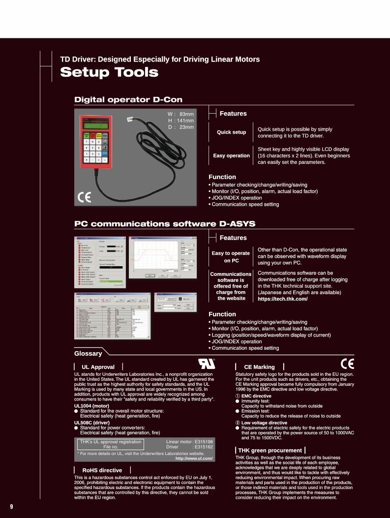
Quick setup Quick setup is possible by simply connecting it to the TD driver.
Easy operationSheet key and highly visible LCD display (16 characters x 2 lines). Even beginners can easily set the parameters.
Function• Parameter checking/change/writing/saving• Monitor (I/O, position, alarm, actual load factor)• JOG/INDEX operation• Communication speed setting
Features
Easy to operate on PC
Other than D-Con, the operational state can be observed with waveform display using your own PC.
Communications software is
offered free of charge from the website
Communications software can be downloaded free of charge after logging in the THK technical support site. (Japanese and English are available)https://tech.thk.com/
Function• Parameter checking/change/writing/saving• Monitor (I/O, position, alarm, actual load factor)• Logging (position/speed/waveform display of current)• JOG/INDEX operation • Communication speed setting
PC communications software D-ASYS
Features
Glossary
Table of Contents
RoHS directive
CE MarkingUL Approval
THK green procurement
This is a hazardous substances control act enforced by EU on July 1, 2006, prohibiting electric and electronic equipment to contain the specified hazardous substances. If the products contain the hazardous substances that are controlled by this directive, they cannot be sold within the EU region.
Statutory safety logo for the products sold in the EU region. For the unit products such as drivers, etc., obtaining the CE Marking approval became fully compulsory from January 1996 by the EMC directive and low voltage directive.
EMC directive Immunity test: Capacity to withstand noise from outside Emission test: Capacity to reduce the release of noise to outside
Low voltage directive Requirement of electric safety for the electric products that are operated by the power source of 50 to 1000VAC and 75 to 1500VDC.
UL stands for Underwriters Laboratories Inc., a nonprofit organization in the United States. The UL standard created by UL has garnered the public trust as the highest authority for safety standards, and the UL Marking is used by many state and local governments in the US. In addition, products with UL approval are widely recognized among consumers to have their "safety and reliability verified by a third party".
UL1004 (motor) Standard for the overall motor structure: Electrical safety (heat generation, fire)UL508C (driver) Standard for power converters: Electrical safety (heat generation, fire)
THK Group, through the development of its business activities as well as the social life of each employee, acknowledges that we are deeply related to global environment, and thus would like to tackle with effectively reducing environmental impact. When procuring raw materials and parts used in the production of the products, or those indirect materials and tools used in the production processes, THK Group implements the measures to consider reducing their impact on the environment.
* For more details on UL, visit the Underwriters Laboratories website. http://www.ul.com/
Linear motor : E315198Driver : E315162
THK's UL approval registrationFile no.
TD Driver: Designed Especially for Driving Linear Motors
Setup Tools Table of Contents
Quick setup Quick setup is possible by simply connecting it to the TD driver.
Easy to operate on PC
Other than D-Con, the operational state can be observed with waveform display using your own PC.
Communications software is
offered free of charge from the website
Communications software can be downloaded free of charge after logging in the THK technical support site. (Japanese and English are available)https://tech.thk.com/
Easy operationSheet key and highly visible LCD display (16 characters x 2 lines). Even beginners can easily set the parameters.
Function• Parameter checking/change/writing/saving• Monitor (I/O, position, alarm, actual load factor)• JOG/INDEX operation• Communication speed setting
Function• Parameter checking/change/writing/saving• Monitor (I/O, position, alarm, actual load factor)• Logging (position/speed/waveform display of current)• JOG/INDEX operation • Communication speed setting
Glossary
Digital operator D-Con
PC communications software D-ASYS
This is a hazardous substances control act enforced by EU on July 1, 2006, prohibiting electric and electronic equipment to contain the specified hazardous substances. If the products contain the hazardous substances that are controlled by this directive, they cannot be sold within the EU region.
RoHS directive
Features
Features
W : 83mm H : 141mm D : 23mm
GLM15
GLM10
GLM20
GLM25
Driver Model TD
Statutory safety logo for the products sold in the EU region. For the unit products such as drivers, etc., obtaining the CE Marking approval became fully compulsory from January 1996 by the EMC directive and low voltage directive.
EMC directive Immunity test: Capacity to withstand noise from outside Emission test: Capacity to reduce the release of noise to outside
Low voltage directive Requirement of electric safety for the electric products that are operated by the power source of 50 to 1000VAC and 75 to 1500VDC.
CE MarkingUL stands for Underwriters Laboratories Inc., a nonprofit organization in the United States. The UL standard created by UL has garnered the public trust as the highest authority for safety standards, and the UL Marking is used by many state and local governments in the US. In addition, products with UL approval are widely recognized among consumers to have their "safety and reliability verified by a third party".
UL1004 (motor) Standard for the overall motor structure: Electrical safety (heat generation, fire)UL508C (driver) Standard for power converters: Electrical safety (heat generation, fire)
UL Approval
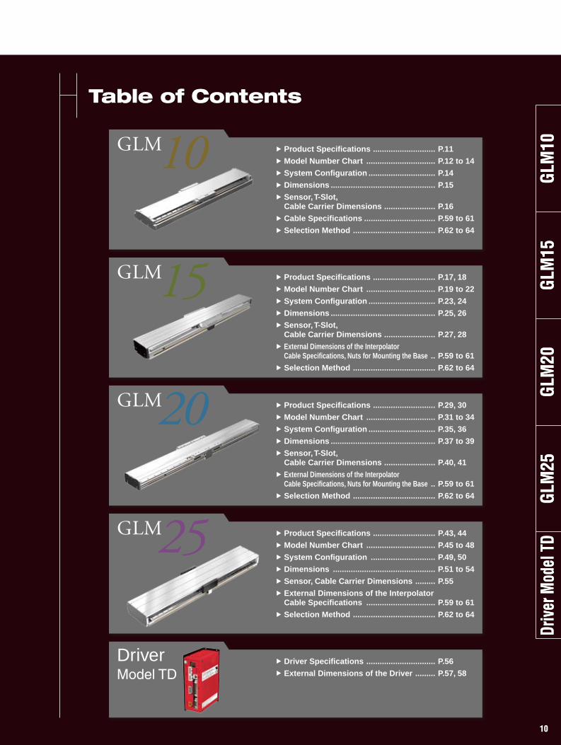
Product Specifications ............................ P.11
Model Number Chart ............................... P.12 to 14
System Configuration .............................. P.14
Dimensions ............................................... P.15
Sensor, T-Slot, Cable Carrier Dimensions ....................... P.16
Cable Specifications ................................ P.59 to 61
Selection Method ..................................... P.62 to 64
Product Specifications ............................ P.17, 18
Model Number Chart ............................... P.19 to 22
System Configuration .............................. P.23, 24
Dimensions ............................................... P.25, 26
Sensor, T-Slot, Cable Carrier Dimensions ....................... P.27, 28
External Dimensions of the InterpolatorCable Specifications, Nuts for Mounting the Base .. P.59 to 61
Selection Method ..................................... P.62 to 64
Product Specifications ............................ P.29, 30
Model Number Chart ............................... P.31 to 34
System Configuration .............................. P.35, 36
Dimensions ............................................... P.37 to 39
Sensor, T-Slot, Cable Carrier Dimensions ....................... P.40, 41
External Dimensions of the InterpolatorCable Specifications, Nuts for Mounting the Base .. P.59 to 61
Selection Method ..................................... P.62 to 64
Product Specifications ............................ P.43, 44
Model Number Chart ............................... P.45 to 48
System Configuration ............................. P.49, 50
Dimensions .............................................. P.51 to 54
Sensor, Cable Carrier Dimensions ......... P.55
External Dimensions of the InterpolatorCable Specifications ............................... P.59 to 61
Selection Method ..................................... P.62 to 64
Driver Specifications ............................... P.56
External Dimensions of the Driver ......... P.57, 58
THK Group, through the development of its business activities as well as the social life of each employee, acknowledges that we are deeply related to global environment, and thus would like to tackle with effectively reducing environmental impact. When procuring raw materials and parts used in the production of the products, or those indirect materials and tools used in the production processes, THK Group implements the measures to consider reducing their impact on the environment.
THK green procurement* For more details on UL, visit the Underwriters Laboratories website.
http://www.ul.com/
Linear motor : E315198Driver : E315162
THK's UL approval registrationFile no.
GLM
20G
LM10
GLM
15G
LM25
Driv
er M
odel
TD
GLM
20G
LM10
GLM
15G
LM25
Driv
er M
odel
TD
9 109 10
TD Driver: Designed Especially for Driving Linear Motors
Setup Tools
Quick setup Quick setup is possible by simply connecting it to the TD driver.
Easy operationSheet key and highly visible LCD display (16 characters x 2 lines). Even beginners can easily set the parameters.
Function• Parameter checking/change/writing/saving• Monitor (I/O, position, alarm, actual load factor)• JOG/INDEX operation• Communication speed setting
Features
Easy to operate on PC
Other than D-Con, the operational state can be observed with waveform display using your own PC.
Communications software is
offered free of charge from the website
Communications software can be downloaded free of charge after logging in the THK technical support site. (Japanese and English are available)https://tech.thk.com/
Function• Parameter checking/change/writing/saving• Monitor (I/O, position, alarm, actual load factor)• Logging (position/speed/waveform display of current)• JOG/INDEX operation • Communication speed setting
PC communications software D-ASYS
Features
Glossary
Table of Contents
RoHS directive
CE MarkingUL Approval
THK green procurement
This is a hazardous substances control act enforced by EU on July 1, 2006, prohibiting electric and electronic equipment to contain the specified hazardous substances. If the products contain the hazardous substances that are controlled by this directive, they cannot be sold within the EU region.
Statutory safety logo for the products sold in the EU region. For the unit products such as drivers, etc., obtaining the CE Marking approval became fully compulsory from January 1996 by the EMC directive and low voltage directive.
EMC directive Immunity test: Capacity to withstand noise from outside Emission test: Capacity to reduce the release of noise to outside
Low voltage directive Requirement of electric safety for the electric products that are operated by the power source of 50 to 1000VAC and 75 to 1500VDC.
UL stands for Underwriters Laboratories Inc., a nonprofit organization in the United States. The UL standard created by UL has garnered the public trust as the highest authority for safety standards, and the UL Marking is used by many state and local governments in the US. In addition, products with UL approval are widely recognized among consumers to have their "safety and reliability verified by a third party".
UL1004 (motor) Standard for the overall motor structure: Electrical safety (heat generation, fire)UL508C (driver) Standard for power converters: Electrical safety (heat generation, fire)
THK Group, through the development of its business activities as well as the social life of each employee, acknowledges that we are deeply related to global environment, and thus would like to tackle with effectively reducing environmental impact. When procuring raw materials and parts used in the production of the products, or those indirect materials and tools used in the production processes, THK Group implements the measures to consider reducing their impact on the environment.
* For more details on UL, visit the Underwriters Laboratories website. http://www.ul.com/
Linear motor : E315198Driver : E315162
THK's UL approval registrationFile no.
TD Driver: Designed Especially for Driving Linear Motors
Setup Tools Table of Contents
Quick setup Quick setup is possible by simply connecting it to the TD driver.
Easy to operate on PC
Other than D-Con, the operational state can be observed with waveform display using your own PC.
Communications software is
offered free of charge from the website
Communications software can be downloaded free of charge after logging in the THK technical support site. (Japanese and English are available)https://tech.thk.com/
Easy operationSheet key and highly visible LCD display (16 characters x 2 lines). Even beginners can easily set the parameters.
Function• Parameter checking/change/writing/saving• Monitor (I/O, position, alarm, actual load factor)• JOG/INDEX operation• Communication speed setting
Function• Parameter checking/change/writing/saving• Monitor (I/O, position, alarm, actual load factor)• Logging (position/speed/waveform display of current)• JOG/INDEX operation • Communication speed setting
Glossary
Digital operator D-Con
PC communications software D-ASYS
This is a hazardous substances control act enforced by EU on July 1, 2006, prohibiting electric and electronic equipment to contain the specified hazardous substances. If the products contain the hazardous substances that are controlled by this directive, they cannot be sold within the EU region.
RoHS directive
Features
Features
W : 83mm H : 141mm D : 23mm
GLM15
GLM10
GLM20
GLM25
Driver Model TD
Statutory safety logo for the products sold in the EU region. For the unit products such as drivers, etc., obtaining the CE Marking approval became fully compulsory from January 1996 by the EMC directive and low voltage directive.
EMC directive Immunity test: Capacity to withstand noise from outside Emission test: Capacity to reduce the release of noise to outside
Low voltage directive Requirement of electric safety for the electric products that are operated by the power source of 50 to 1000VAC and 75 to 1500VDC.
CE MarkingUL stands for Underwriters Laboratories Inc., a nonprofit organization in the United States. The UL standard created by UL has garnered the public trust as the highest authority for safety standards, and the UL Marking is used by many state and local governments in the US. In addition, products with UL approval are widely recognized among consumers to have their "safety and reliability verified by a third party".
UL1004 (motor) Standard for the overall motor structure: Electrical safety (heat generation, fire)UL508C (driver) Standard for power converters: Electrical safety (heat generation, fire)
UL Approval
Product Specifications ............................ P.11
Model Number Chart ............................... P.12 to 14
System Configuration .............................. P.14
Dimensions ............................................... P.15
Sensor, T-Slot, Cable Carrier Dimensions ....................... P.16
Cable Specifications ................................ P.59 to 61
Selection Method ..................................... P.62 to 64
Product Specifications ............................ P.17, 18
Model Number Chart ............................... P.19 to 22
System Configuration .............................. P.23, 24
Dimensions ............................................... P.25, 26
Sensor, T-Slot, Cable Carrier Dimensions ....................... P.27, 28
External Dimensions of the InterpolatorCable Specifications, Nuts for Mounting the Base .. P.59 to 61
Selection Method ..................................... P.62 to 64
Product Specifications ............................ P.29, 30
Model Number Chart ............................... P.31 to 34
System Configuration .............................. P.35, 36
Dimensions ............................................... P.37 to 39
Sensor, T-Slot, Cable Carrier Dimensions ....................... P.40, 41
External Dimensions of the InterpolatorCable Specifications, Nuts for Mounting the Base .. P.59 to 61
Selection Method ..................................... P.62 to 64
Product Specifications ............................ P.43, 44
Model Number Chart ............................... P.45 to 48
System Configuration ............................. P.49, 50
Dimensions .............................................. P.51 to 54
Sensor, Cable Carrier Dimensions ......... P.55
External Dimensions of the InterpolatorCable Specifications ............................... P.59 to 61
Selection Method ..................................... P.62 to 64
Driver Specifications ............................... P.56
External Dimensions of the Driver ......... P.57, 58
THK Group, through the development of its business activities as well as the social life of each employee, acknowledges that we are deeply related to global environment, and thus would like to tackle with effectively reducing environmental impact. When procuring raw materials and parts used in the production of the products, or those indirect materials and tools used in the production processes, THK Group implements the measures to consider reducing their impact on the environment.
THK green procurement* For more details on UL, visit the Underwriters Laboratories website.
http://www.ul.com/
Linear motor : E315198Driver : E315162
THK's UL approval registrationFile no.
GLM
20G
LM10
GLM
15G
LM25
Driv
er M
odel
TD
GLM
20G
LM10
GLM
15G
LM25
Driv
er M
odel
TD
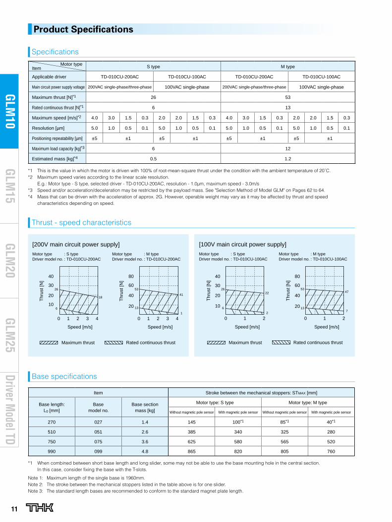
11
Driver Model TD
GLM
20G
LM10
GLM
15G
LM25
Product Specifications
Motor typeItem S type M type
Applicable driver TD-010CU-200AC TD-010CU-100AC TD-010CU-200AC TD-010CU-100AC
Main circuit power supply voltage 200VAC single-phase/three-phase 100VAC single-phase 200VAC single-phase/three-phase 100VAC single-phase
Maximum thrust [N]*1 26 53
Rated continuous thrust [N]*1 6 13
Maximum speed [m/s]*2 4.0 3.0 1.5 0.3 2.0 2.0 1.5 0.3 4.0 3.0 1.5 0.3 2.0 2.0 1.5 0.3
Resolution [μm] 5.0 1.0 0.5 0.1 5.0 1.0 0.5 0.1 5.0 1.0 0.5 0.1 5.0 1.0 0.5 0.1
Positioning repeatability [μm] ±5 ±1 ±5 ±1 ±5 ±1 ±5 ±1
Maximum load capacity [kg]*3 6 12
Estimated mass [kg]*4 0.5 1.2
*1 This is the value in which the motor is driven with 100% of root-mean-square thrust under the condition with the ambient temperature of 20˚C.*2 Maximum speed varies according to the linear scale resolution.
E.g.: Motor type - S type, selected driver - TD-010CU-200AC, resolution - 1.0μm, maximum speed - 3.0m/s*3 Speed and/or acceleration/deceleration may be restricted by the payload mass. See "Selection Method of Model GLM" on Pages 62 to 64.*4 Mass that can be driven with the acceleration of approx. 2G. However, operable weight may vary as it may be affected by thrust and speed
characteristics depending on speed.
Thrust - speed characteristics
Item Stroke between the mechanical stoppers: STMAX [mm]
Base length: L0 [mm]
Basemodel no.
Base sectionmass [kg]
Motor type: S type Motor type: M type
Without magnetic pole sensor With magnetic pole sensor Without magnetic pole sensor With magnetic pole sensor
270 027 1.4 145 100*1 85*1 40*1
510 051 2.6 385 340 325 280
750 075 3.6 625 580 565 520
990 099 4.8 865 820 805 760
*1 When combined between short base length and long slider, some may not be able to use the base mounting hole in the central section. In this case, consider fixing the base with the T-slots.
Note 1: Maximum length of the single base is 1960mm.Note 2: The stroke between the mechanical stoppers listed in the table above is for one slider.Note 3: The standard length bases are recommended to conform to the standard magnet plate length.
Base specifications
Specifications
4
Speed [m/s]
10
20
40
30
20
40
20 1 3420 1 3
80
60
Speed [m/s]
Thr
ust [
N]
Thr
ust [
N]
Motor type : S typeDriver model no. : TD-010CU-200AC
Motor type : M typeDriver model no. : TD-010CU-200AC
[200V main circuit power supply]
26
6
18
13
53
41
1
Maximum thrust Rated continuous thrust
[100V main circuit power supply]
0
20
10
21
40
30
0
40
20
1 2
80
60
Speed [m/s] Speed [m/s]
Maximum thrust Rated continuous thrust
6
2622
2
13
5347
7
Motor type : S typeDriver model no. : TD-010CU-100AC
Motor type : M typeDriver model no. : TD-010CU-100AC
Thr
ust [
N]
Thr
ust [
N]
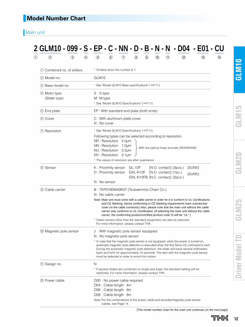
12
GLM
20G
LM10
GLM
15G
LM25
Driv
er M
odel
TD
Combined no. of sliders * Omitted when the number is 1.
Model no. GLM10
Base model no. * See "Model GLM10 Base specifications" (g P.11).
Motor type (Slider size)
S : S typeM : M type* See "Model GLM10 Specifications" (g P.11).
End plate EP : With standard end plate (both ends)
Cover C : With aluminum plate coverN : No cover
Resolution * See "Model GLM10 Specifications" (g P.11).
Following types can be selected according to resolution.NR : Resolution 5.0μmNN : Resolution 1.0μmNU : Resolution 0.5μmNV : Resolution 0.1μm* The values of resolution are after quadrature.
Sensor K : Proximity sensor GL-12F [N.O. contact] (3pcs.) (SUNX)D : Proximity sensor GXL-N12F [N.O. contact] (1pc.) (SUNX) GXL-N12FB [N.C. contact] (2pcs.)N : No sensor
Cable carrier B : TKP0180W40R37 (Tsubakimoto Chain Co.)N : No cable carrierNote: Main unit must come with a cable carrier in order for it to conform to UL Certifications
and CE Marking. (Items conforming to CE Marking requirements have a protective cover on the cable connector) Also, please note that the main unit without the cable carrier only conforms to UL Certification. (If selecting the main unit without the cable carrier, the conforming product/certified product code will be "UL".)
* Cable carriers other than the standard equipment can also be selected. For more information, please contact THK.
Magnetic pole sensor J : With magnetic pole sensor equippedN : No magnetic pole sensor* In case that the magnetic pole sensor is not equipped, when the power is turned on,
automatic magnetic pole detection is executed when the first Servo-On command is sent. During the automatic magnetic pole detection, the slider will travel several millimeters back and forth for approximately 10 seconds. The item with the magnetic pole sensor must be selected in order to avoid this motion.
Design no. N* If several sliders are combined on single axis base, the standard setting will be
restricted. For more information, please contact THK.
Power cable D00 : No power cable requiredD04 : Cable length 4mD06 : Cable length 6mD08 : Cable length 8mNote: For the combinations of the power cable and encoder/magnetic pole sensor
cables, see Page 14.
Model Number Chart
2 GLM10 - 099 - S - EP - C - NN - D - B - N - N - D04 - E01 - CU
Main unit
[The model number chart for the main unit continues on the next page]
With the optical linear encoder (RENISHAW)
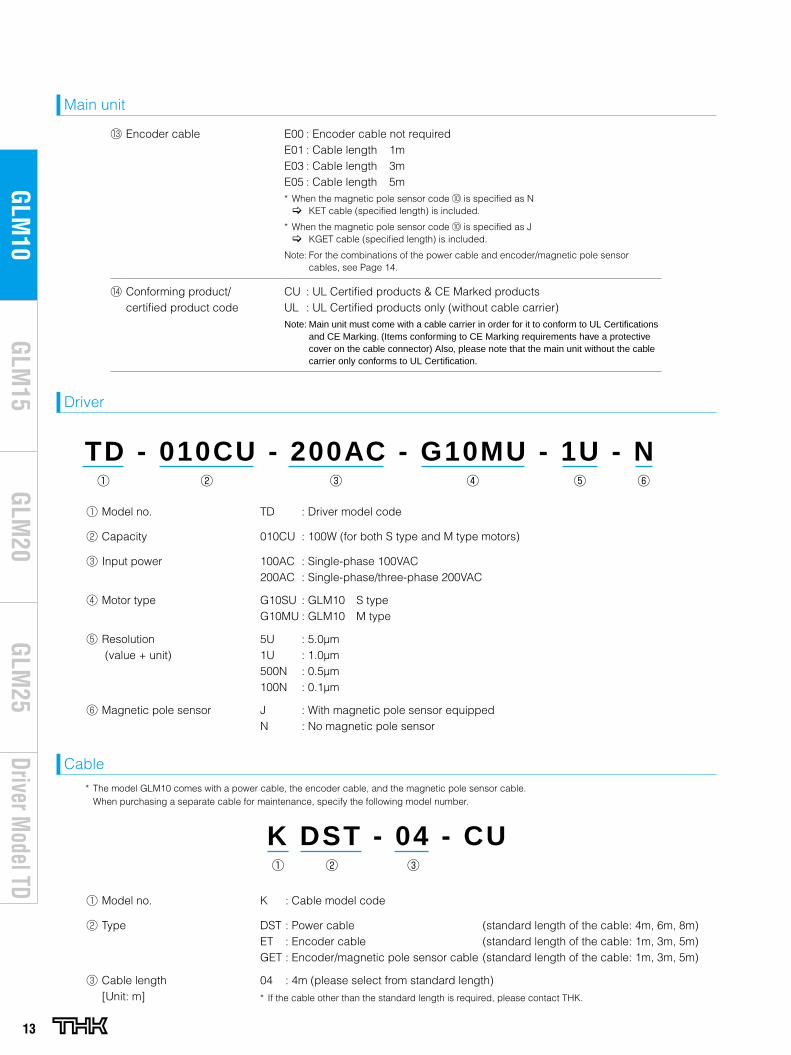
13
Driver Model TD
GLM
20G
LM10
GLM
15G
LM25
Main unit
TD - 010CU - 200AC - G10MU - 1U - N
Driver
K DST - 04 - CU
Cable
* The model GLM10 comes with a power cable, the encoder cable, and the magnetic pole sensor cable. When purchasing a separate cable for maintenance, specify the following model number.
Encoder cable E00 : Encoder cable not requiredE01 : Cable length 1mE03 : Cable length 3mE05 : Cable length 5m* When the magnetic pole sensor code is specified as N [ KET cable (specified length) is included.
* When the magnetic pole sensor code is specified as J [ KGET cable (specified length) is included.
Note: For the combinations of the power cable and encoder/magnetic pole sensor cables, see Page 14.
Conforming product/ certified product code
CU : UL Certified products & CE Marked productsUL : UL Certified products only (without cable carrier) Note: Main unit must come with a cable carrier in order for it to conform to UL Certifications
and CE Marking. (Items conforming to CE Marking requirements have a protective cover on the cable connector) Also, please note that the main unit without the cable carrier only conforms to UL Certification.
Model no. TD : Driver model code
Capacity 010CU : 100W (for both S type and M type motors)
Input power 100AC : Single-phase 100VAC200AC : Single-phase/three-phase 200VAC
Motor type G10SU : GLM10 S typeG10MU : GLM10 M type
Resolution (value + unit)
5U : 5.0μm1U : 1.0μm500N : 0.5μm100N : 0.1μm
Magnetic pole sensor J : With magnetic pole sensor equippedN : No magnetic pole sensor
Model no. K : Cable model code
Type DST : Power cable (standard length of the cable: 4m, 6m, 8m)ET : Encoder cable (standard length of the cable: 1m, 3m, 5m)GET : Encoder/magnetic pole sensor cable (standard length of the cable: 1m, 3m, 5m)
Cable length[Unit: m]
04 : 4m (please select from standard length)
* If the cable other than the standard length is required, please contact THK.
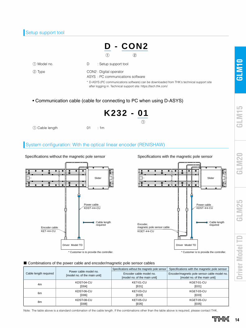
14
GLM
20G
LM10
GLM
15G
LM25
Driv
er M
odel
TD
D - CON2
K232 - 01
Setup support tool
System configuration: With the optical linear encoder (RENISHAW)
• Communication cable (cable for connecting to PC when using D-ASYS)
Cable length requiredPower cable model no.
[model no. of the main unit]
Specifications without the magnetic pole sensor Specifications with the magnetic pole sensor
Encoder cable model no. [model no. of the main unit]
Encoder/magnetic pole sensor cable model no. [model no. of the main unit]
4mKDST-04-CU
[D04]KET-01-CU
[E01]KGET-01-CU
[E01]
6mKDST-06-CU
[D06]KET-03-CU
[E03]KGET-03-CU
[E03]
8mKDST-08-CU
[D08]KET-05-CU
[E05]KGET-05-CU
[E05]
Note: The table above is a standard combination of the cable length. If the combinations other than the table above is required, please contact THK.
Driver Model TD
Encoder, magnetic pole sensor cable
Slider
KDST-∗∗-CUPower cable
KGET-∗∗-CU
Specifications without the magnetic pole sensor Specifications with the magnetic pole sensor
Driver Model TD
Encoder cable
Slider
KDST-∗∗-CUPower cable
KET-∗∗-CU
* Customer is to provide the controller. * Customer is to provide the controller.
: Cable length required
: Cable length required
¢ Combinations of the power cable and encoder/magnetic pole sensor cables
Model no. D : Setup support tool
Type CON2 : Digital operatorASYS : PC communications software
* D-ASYS (PC communications software) can be downloaded from THK's technical support site after logging in. Technical support site: https://tech.thk.com/
Cable length 01 : 1m
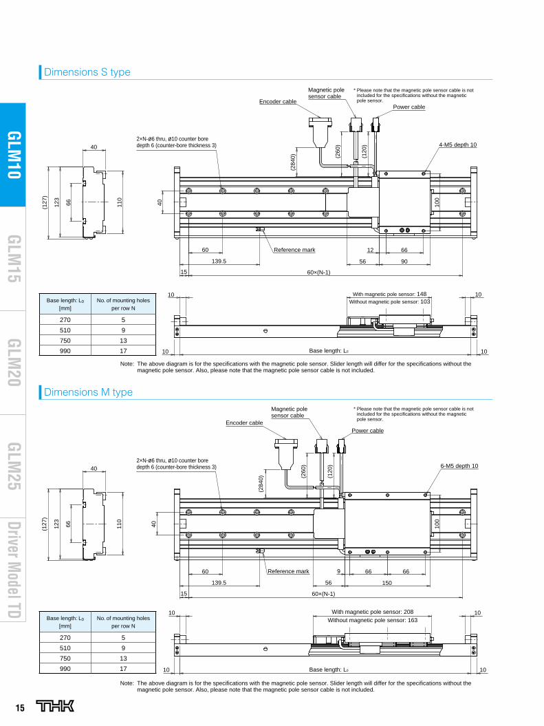
15
Driver Model TD
GLM
20G
LM10
GLM
15G
LM25
Dimensions S type
Dimensions M type
2×N-ø6 thru, ø10 counter bore depth 6 (counter-bore thickness 3)
66123
(127
)
110
66123
(127
)
110
40
40 100
100
60
139.5
15 60×(N-1)
66
90
(260
)
(120
)
(284
0)
(260
)
(120
)
(284
0)
With magnetic pole sensor: 148
Base length: L0
56
2×N-ø6 thru, ø10 counter bore depth 6 (counter-bore thickness 3)
Encoder cable
Magnetic pole sensor cable
Power cable
4-M5 depth 10
Reference mark 12
10 10
10
40
40
60
139.5
15 60×(N-1)
9 66 66
15056
With magnetic pole sensor: 208
10 Base length: L0 10
Encoder cablePower cable
6-M5 depth 10
Reference mark
10Without magnetic pole sensor: 103
Without magnetic pole sensor: 163
* Please note that the magnetic pole sensor cable is not included for the specifications without the magnetic pole sensor.
Note: The above diagram is for the specifications with the magnetic pole sensor. Slider length will differ for the specifications without the magnetic pole sensor. Also, please note that the magnetic pole sensor cable is not included.
Magnetic pole sensor cable
* Please note that the magnetic pole sensor cable is not included for the specifications without the magnetic pole sensor.
Note: The above diagram is for the specifications with the magnetic pole sensor. Slider length will differ for the specifications without the magnetic pole sensor. Also, please note that the magnetic pole sensor cable is not included.
1010
Base length: L0
[mm]No. of mounting holes
per row N
270 5
510 9
750 13
990 17
2×N-ø6 thru, ø10 counter bore depth 6 (counter-bore thickness 3)
66123
(127
)
110
66123
(127
)
110
40
40 100
100
60
139.5
15 60×(N-1)
66
90
(260
)
(120
)
(284
0)
(260
)
(120
)
(284
0)
With magnetic pole sensor: 148
Base length: L0
56
2×N-ø6 thru, ø10 counter bore depth 6 (counter-bore thickness 3)
Encoder cable
Magnetic pole sensor cable
Power cable
4-M5 depth 10
Reference mark 12
10 10
10
40
40
60
139.5
15 60×(N-1)
9 66 66
15056
With magnetic pole sensor: 208
10 Base length: L0 10
Encoder cablePower cable
6-M5 depth 10
Reference mark
10Without magnetic pole sensor: 103
Without magnetic pole sensor: 163
* Please note that the magnetic pole sensor cable is not included for the specifications without the magnetic pole sensor.
Note: The above diagram is for the specifications with the magnetic pole sensor. Slider length will differ for the specifications without the magnetic pole sensor. Also, please note that the magnetic pole sensor cable is not included.
Magnetic pole sensor cable
* Please note that the magnetic pole sensor cable is not included for the specifications without the magnetic pole sensor.
Note: The above diagram is for the specifications with the magnetic pole sensor. Slider length will differ for the specifications without the magnetic pole sensor. Also, please note that the magnetic pole sensor cable is not included.
1010Base length: L0
[mm]No. of mounting holes
per row N
270 5
510 9
750 13
990 17
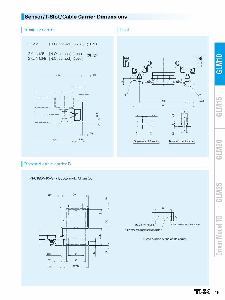
16
GLM
20G
LM10
GLM
15G
LM25
Driv
er M
odel
TD
Sensor/T-Slot/Cable Carrier Dimensions
Proximity sensor
(12.5)
(3)
(2.5
)
(4)110
87
GL-12F [N.O. contact] (3pcs.) (SUNX)
GXL-N12F [N.O. contact] (1pc.) (SUNX)GXL-N12FB [N.C. contact] (2pcs.)
T-slot
66
9
10.5
87
AB
5
5
8
1.5
30.
5
5.8
3.6
2 3.5
Dimensions of B section Dimensions of A section
Standard cable carrier B
TKP0180W40R37 (Tsubakimoto Chain Co.)
(67.5)
49
40
(74)
(1.5
)(1
01)
(4)
(44)
14
(10)
123
87
110
(11)
40
14
ø9.5 power cable
ø8.7 magnetic pole sensor cable
ø8.7 linear encoder cable
Cross section of the cable carrier
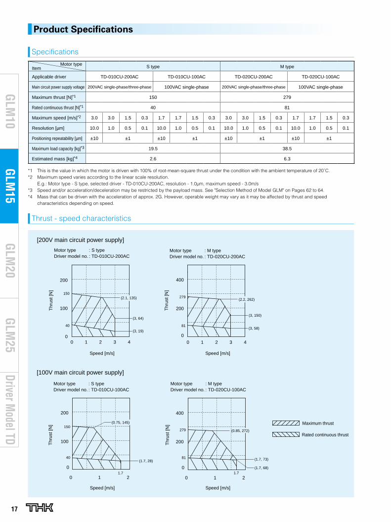
17
Driver Model TD
GLM
20G
LM10
GLM
15G
LM25
Product Specifications
Motor typeItem S type M type
Applicable driver TD-010CU-200AC TD-010CU-100AC TD-020CU-200AC TD-020CU-100AC
Main circuit power supply voltage 200VAC single-phase/three-phase 100VAC single-phase 200VAC single-phase/three-phase 100VAC single-phase
Maximum thrust [N]*1 150 279
Rated continuous thrust [N]*1 40 81
Maximum speed [m/s]*2 3.0 3.0 1.5 0.3 1.7 1.7 1.5 0.3 3.0 3.0 1.5 0.3 1.7 1.7 1.5 0.3
Resolution [μm] 10.0 1.0 0.5 0.1 10.0 1.0 0.5 0.1 10.0 1.0 0.5 0.1 10.0 1.0 0.5 0.1
Positioning repeatability [μm] ±10 ±1 ±10 ±1 ±10 ±1 ±10 ±1
Maximum load capacity [kg]*3 19.5 38.5
Estimated mass [kg]*4 2.6 6.3
*1 This is the value in which the motor is driven with 100% of root-mean-square thrust under the condition with the ambient temperature of 20˚C.*2 Maximum speed varies according to the linear scale resolution.
E.g.: Motor type - S type, selected driver - TD-010CU-200AC, resolution - 1.0μm, maximum speed - 3.0m/s*3 Speed and/or acceleration/deceleration may be restricted by the payload mass. See "Selection Method of Model GLM" on Pages 62 to 64.*4 Mass that can be driven with the acceleration of approx. 2G. However, operable weight may vary as it may be affected by thrust and speed
characteristics depending on speed.
Thrust - speed characteristics
Specifications
Motor type : S typeDriver model no. : TD-010CU-200AC
Motor type : M typeDriver model no. : TD-020CU-200AC
[200V main circuit power supply]
200
0
100
Speed [m/s]Speed [m/s]
Thr
ust [
N]
0 21 3 4
Thr
ust [
N]
0
0 1 32 4
400
200
150
40
(2.1, 135)
(3, 64)
(3, 19)
279
81
(2.2, 262)
(3, 150)
(3, 58)
[100V main circuit power supply]
Motor type : S typeDriver model no. : TD-010CU-100AC
Motor type : M typeDriver model no. : TD-020CU-100AC
Maximum thrust
Rated continuous thrust
0
100
200
0 1 2
200
0
0 1 2
400
Speed [m/s]
Thr
ust [
N]
Speed [m/s]
Thr
ust [
N]
1.7
150
40
(0.75, 145)
(1.7, 28)
1.7
279
81
(0.85, 272)
(1.7, 73)
(1.7, 68)
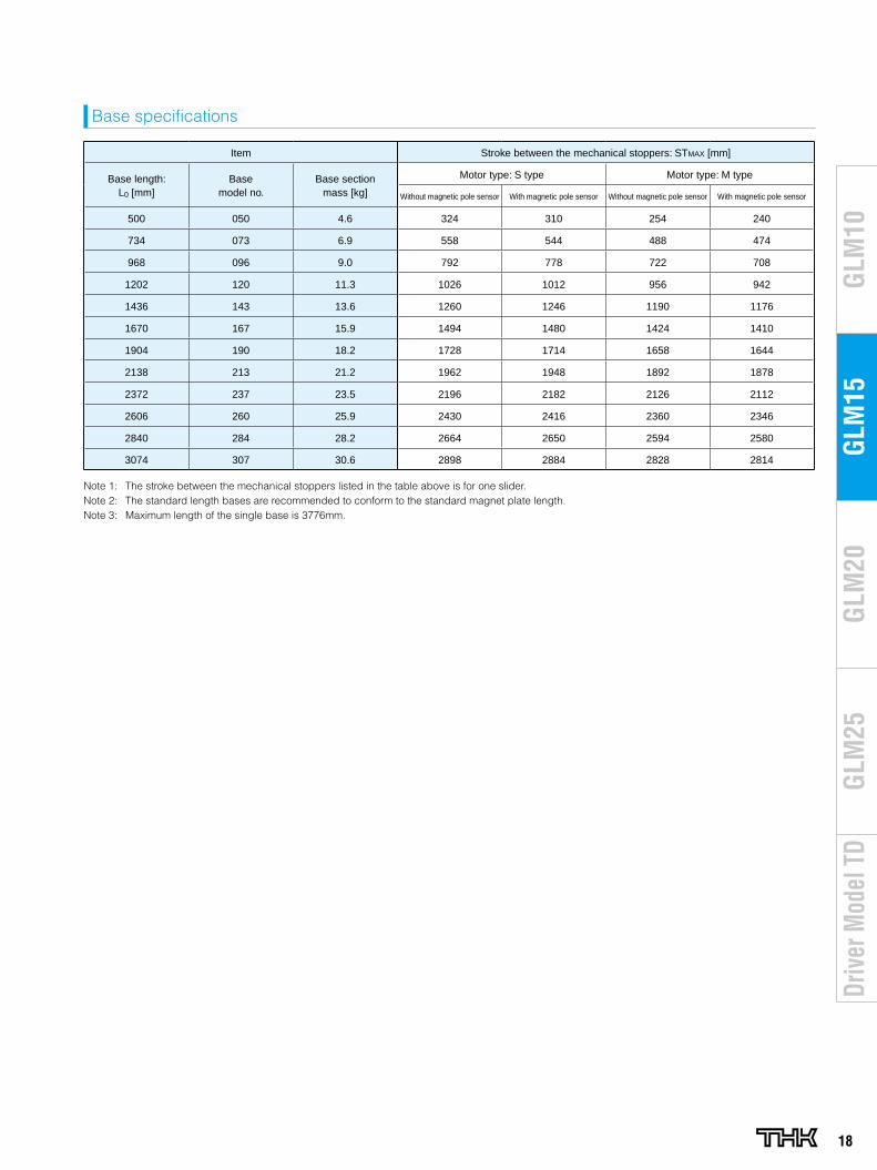
18
GLM
20G
LM10
GLM
15G
LM25
Driv
er M
odel
TD
Item Stroke between the mechanical stoppers: STMAX [mm]
Base length: L0 [mm]
Basemodel no.
Base sectionmass [kg]
Motor type: S type Motor type: M type
Without magnetic pole sensor With magnetic pole sensor Without magnetic pole sensor With magnetic pole sensor
500 050 4.6 324 310 254 240
734 073 6.9 558 544 488 474
968 096 9.0 792 778 722 708
1202 120 11.3 1026 1012 956 942
1436 143 13.6 1260 1246 1190 1176
1670 167 15.9 1494 1480 1424 1410
1904 190 18.2 1728 1714 1658 1644
2138 213 21.2 1962 1948 1892 1878
2372 237 23.5 2196 2182 2126 2112
2606 260 25.9 2430 2416 2360 2346
2840 284 28.2 2664 2650 2594 2580
3074 307 30.6 2898 2884 2828 2814
Note 1: The stroke between the mechanical stoppers listed in the table above is for one slider.Note 2: The standard length bases are recommended to conform to the standard magnet plate length.Note 3: Maximum length of the single base is 3776mm.
Base specifications
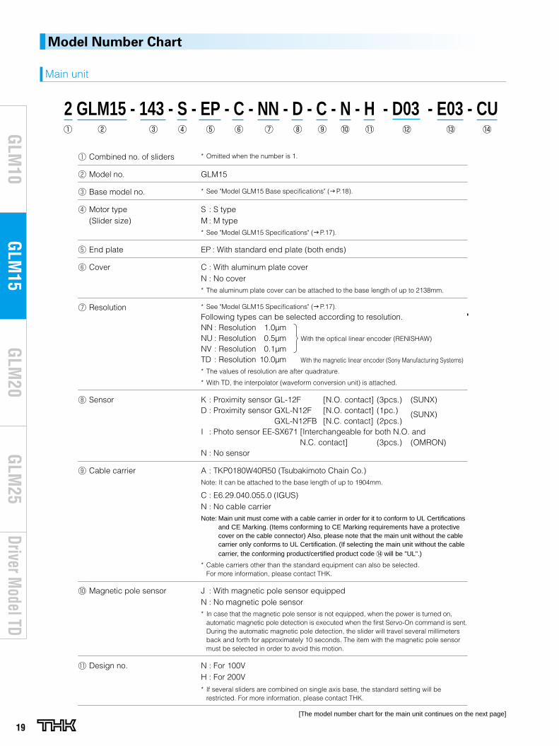
19
Driver Model TD
GLM
20G
LM10
GLM
15G
LM25
Combined no. of sliders * Omitted when the number is 1.
Model no. GLM15
Base model no. * See "Model GLM15 Base specifications" (g P.18).
Motor type(Slider size)
S : S typeM : M type* See "Model GLM15 Specifications" (g P.17).
End plate EP : With standard end plate (both ends)
Cover C : With aluminum plate coverN : No cover* The aluminum plate cover can be attached to the base length of up to 2138mm.
Resolution * See "Model GLM15 Specifications" (g P.17).
Following types can be selected according to resolution.NN : Resolution 1.0μmNU : Resolution 0.5μmNV : Resolution 0.1μmTD : Resolution 10.0μm* The values of resolution are after quadrature.
* With TD, the interpolator (waveform conversion unit) is attached.
Sensor K : Proximity sensor GL-12F [N.O. contact] (3pcs.) (SUNX)D : Proximity sensor GXL-N12F [N.O. contact] (1pc.) (SUNX)
GXL-N12FB [N.C. contact] (2pcs.)I : Photo sensor EE-SX671 [Interchangeable for both N.O. and
N.C. contact] (3pcs.) (OMRON)N : No sensor
Cable carrier A : TKP0180W40R50 (Tsubakimoto Chain Co.)Note: It can be attached to the base length of up to 1904mm.
C : E6.29.040.055.0 (IGUS)N : No cable carrierNote: Main unit must come with a cable carrier in order for it to conform to UL Certifications
and CE Marking. (Items conforming to CE Marking requirements have a protective cover on the cable connector) Also, please note that the main unit without the cable carrier only conforms to UL Certification. (If selecting the main unit without the cable carrier, the conforming product/certified product code will be "UL".)
* Cable carriers other than the standard equipment can also be selected. For more information, please contact THK.
Magnetic pole sensor J : With magnetic pole sensor equippedN : No magnetic pole sensor* In case that the magnetic pole sensor is not equipped, when the power is turned on,
automatic magnetic pole detection is executed when the first Servo-On command is sent. During the automatic magnetic pole detection, the slider will travel several millimeters back and forth for approximately 10 seconds. The item with the magnetic pole sensor must be selected in order to avoid this motion.
Design no. N : For 100VH : For 200V
* If several sliders are combined on single axis base, the standard setting will be restricted. For more information, please contact THK.
Model Number Chart
2 GLM15 - 143 - S - EP - C - NN - D - C - N - H - D03 - E03 - CU
Main unit
[The model number chart for the main unit continues on the next page]
With the optical linear encoder (RENISHAW)
With the magnetic linear encoder (Sony Manufacturing Systems)
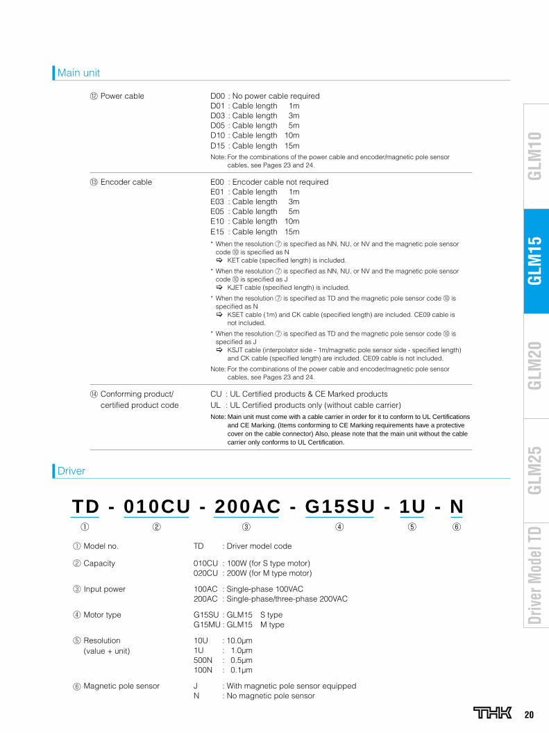
20
GLM
20G
LM10
GLM
15G
LM25
Driv
er M
odel
TD
Model no. TD : Driver model code
Capacity 010CU : 100W (for S type motor)020CU : 200W (for M type motor)
Input power 100AC : Single-phase 100VAC200AC : Single-phase/three-phase 200VAC
Motor type G15SU : GLM15 S typeG15MU : GLM15 M type
Resolution(value + unit)
10U : 10.0μm1U : 1.0μm500N : 0.5μm100N : 0.1μm
Magnetic pole sensor J : With magnetic pole sensor equippedN : No magnetic pole sensor
Power cable D00 : No power cable requiredD01 : Cable length 1mD03 : Cable length 3mD05 : Cable length 5mD10 : Cable length 10mD15 : Cable length 15mNote: For the combinations of the power cable and encoder/magnetic pole sensor
cables, see Pages 23 and 24.
Encoder cable E00 : Encoder cable not requiredE01 : Cable length 1mE03 : Cable length 3mE05 : Cable length 5mE10 : Cable length 10mE15 : Cable length 15m
* When the resolution is specified as NN, NU, or NV and the magnetic pole sensor code is specified as N [ KET cable (specified length) is included.
* When the resolution is specified as NN, NU, or NV and the magnetic pole sensor code is specified as J [ KJET cable (specified length) is included.
* When the resolution is specified as TD and the magnetic pole sensor code is specified as N [ KSET cable (1m) and CK cable (specified length) are included. CE09 cable is
not included.
* When the resolution is specified as TD and the magnetic pole sensor code is specified as J [ KSJT cable (interpolator side - 1m/magnetic pole sensor side - specified length)
and CK cable (specified length) are included. CE09 cable is not included.
Note: For the combinations of the power cable and encoder/magnetic pole sensor cables, see Pages 23 and 24.
Conforming product/ certified product code
CU : UL Certified products & CE Marked productsUL : UL Certified products only (without cable carrier) Note: Main unit must come with a cable carrier in order for it to conform to UL Certifications
and CE Marking. (Items conforming to CE Marking requirements have a protective cover on the cable connector) Also, please note that the main unit without the cable carrier only conforms to UL Certification.
Main unit
TD - 010CU - 200AC - G15SU - 1U - N
Driver
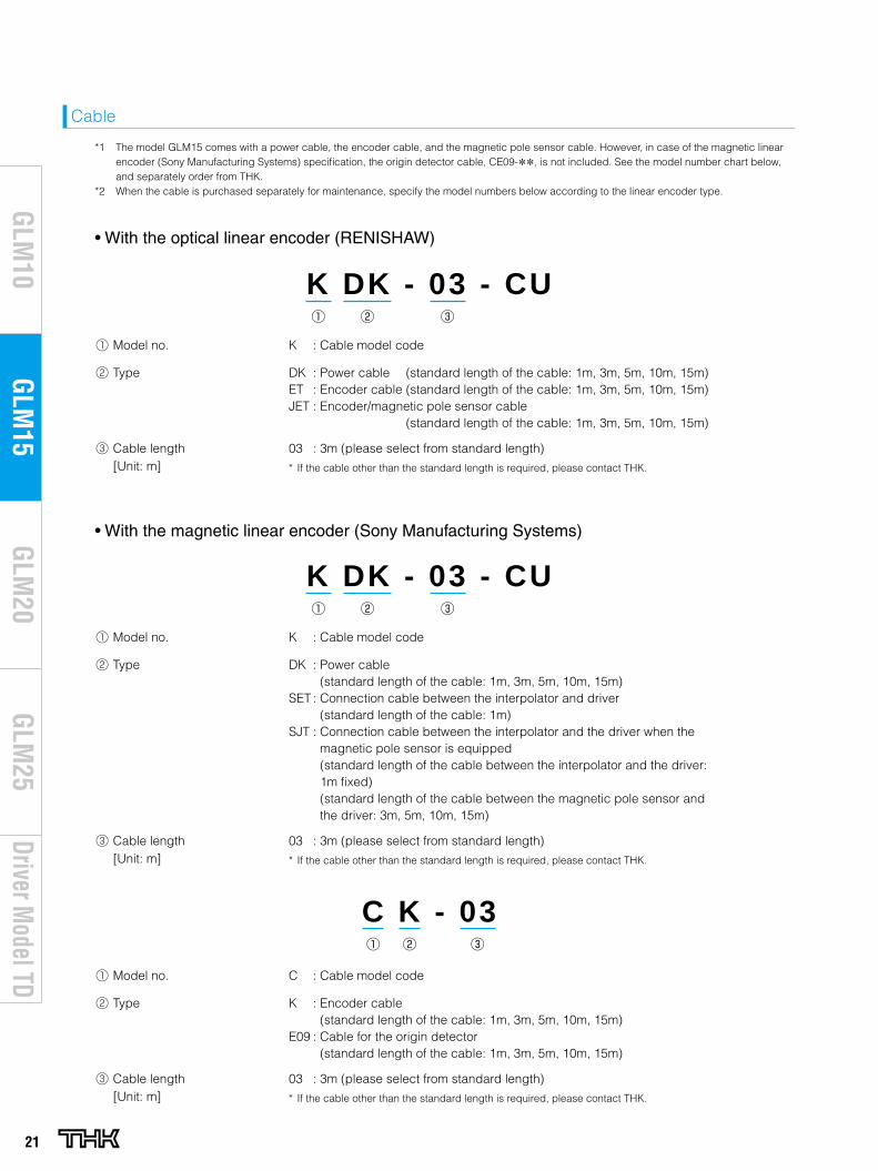
21
Driver Model TD
GLM
20G
LM10
GLM
15G
LM25
Model no. K : Cable model code
Type DK : Power cable (standard length of the cable: 1m, 3m, 5m, 10m, 15m)
SET : Connection cable between the interpolator and driver (standard length of the cable: 1m)
SJT : Connection cable between the interpolator and the driver when the magnetic pole sensor is equipped (standard length of the cable between the interpolator and the driver: 1m fixed) (standard length of the cable between the magnetic pole sensor and the driver: 3m, 5m, 10m, 15m)
Cable length[Unit: m]
03 : 3m (please select from standard length)
* If the cable other than the standard length is required, please contact THK.
Model no. K : Cable model code
Type DK : Power cable (standard length of the cable: 1m, 3m, 5m, 10m, 15m)ET : Encoder cable (standard length of the cable: 1m, 3m, 5m, 10m, 15m)JET : Encoder/magnetic pole sensor cable (standard length of the cable: 1m, 3m, 5m, 10m, 15m)
Cable length[Unit: m]
03 : 3m (please select from standard length)
* If the cable other than the standard length is required, please contact THK.
K DK - 03 - CU
• With the optical linear encoder (RENISHAW)
Cable
*1 The model GLM15 comes with a power cable, the encoder cable, and the magnetic pole sensor cable. However, in case of the magnetic linear encoder (Sony Manufacturing Systems) specification, the origin detector cable, CE09-**, is not included. See the model number chart below, and separately order from THK.
*2 When the cable is purchased separately for maintenance, specify the model numbers below according to the linear encoder type.
K DK - 03 - CU
• With the magnetic linear encoder (Sony Manufacturing Systems)
C K - 03
Model no. C : Cable model code
Type K : Encoder cable (standard length of the cable: 1m, 3m, 5m, 10m, 15m)
E09 : Cable for the origin detector (standard length of the cable: 1m, 3m, 5m, 10m, 15m)
Cable length[Unit: m]
03 : 3m (please select from standard length)
* If the cable other than the standard length is required, please contact THK.
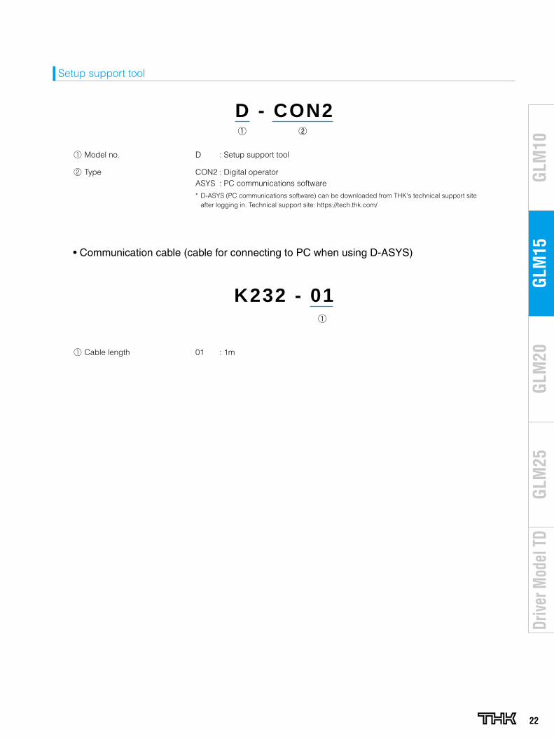
22
GLM
20G
LM10
GLM
15G
LM25
Driv
er M
odel
TD
Cable length 01 : 1m
Model no. D : Setup support tool
Type CON2 : Digital operatorASYS : PC communications software
* D-ASYS (PC communications software) can be downloaded from THK's technical support site after logging in. Technical support site: https://tech.thk.com/
D - CON2
Setup support tool
K232 - 01
• Communication cable (cable for connecting to PC when using D-ASYS)
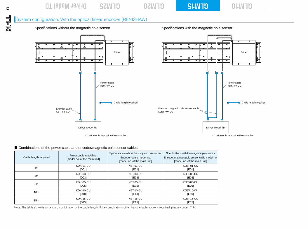
23
Driver Model TD GLM20 GLM10GLM15GLM25
System configuration: With the optical linear encoder (RENISHAW)
Cable length requiredPower cable model no.
[model no. of the main unit]
Specifications without the magnetic pole sensor Specifications with the magnetic pole sensor
Encoder cable model no. [model no. of the main unit]
Encoder/magnetic pole sensor cable model no. [model no. of the main unit]
1mKDK-01-CU
[D01]KET-01-CU
[E01]KJET-01-CU
[E01]
3mKDK-03-CU
[D03]KET-03-CU
[E03]KJET-03-CU
[E03]
5mKDK-05-CU
[D05]KET-05-CU
[E05]KJET-05-CU
[E05]
10mKDK-10-CU
[D10]KET-10-CU
[E10]KJET-10-CU
[E10]
15mKDK-15-CU
[D15]KET-15-CU
[E15]KJET-15-CU
[E15]
Note: The table above is a standard combination of the cable length. If the combinations other than the table above is required, please contact THK.
Driver Model TD
Encoder, magnetic pole sensor cable
Slider
KDK-∗∗-CUPower cable
KJET-∗∗-CU
Specifications without the magnetic pole sensor Specifications with the magnetic pole sensor
Driver Model TD
Encoder cable
Slider
KDK-∗∗-CUPower cable
KET-∗∗-CU
* Customer is to provide the controller. * Customer is to provide the controller.
: Cable length required : Cable length required
¢ Combinations of the power cable and encoder/magnetic pole sensor cables
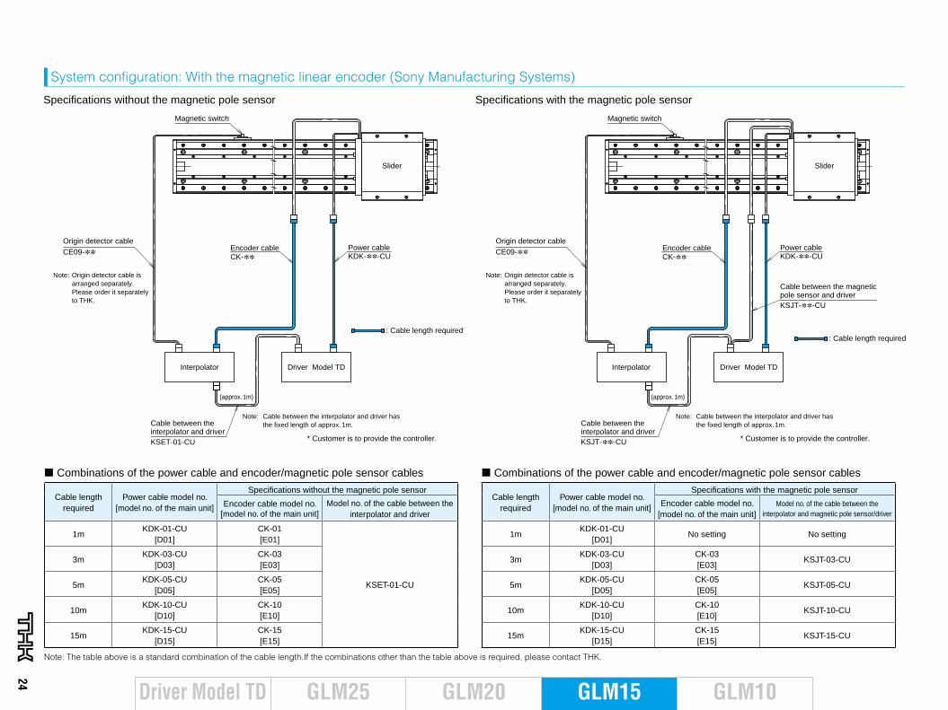
24
GLM20 GLM10GLM15GLM25Driver Model TD
System configuration: With the magnetic linear encoder (Sony Manufacturing Systems)
Cable length required
Power cable model no. [model no. of the main unit]
Specifications without the magnetic pole sensor
Encoder cable model no. [model no. of the main unit]
Model no. of the cable between theinterpolator and driver
1mKDK-01-CU
[D01]CK-01 [E01]
KSET-01-CU
3mKDK-03-CU
[D03]CK-03 [E03]
5mKDK-05-CU
[D05]CK-05 [E05]
10mKDK-10-CU
[D10]CK-10 [E10]
15mKDK-15-CU
[D15]CK-15 [E15]
Note: The table above is a standard combination of the cable length.If the combinations other than the table above is required, please contact THK.
Cable length required
Power cable model no. [model no. of the main unit]
Specifications with the magnetic pole sensor
Encoder cable model no. [model no. of the main unit]
Model no. of the cable between the interpolator and magnetic pole sensor/driver
1mKDK-01-CU
[D01]No setting No setting
3mKDK-03-CU
[D03]CK-03 [E03]
KSJT-03-CU
5mKDK-05-CU
[D05]CK-05 [E05]
KSJT-05-CU
10mKDK-10-CU
[D10]CK-10 [E10]
KSJT-10-CU
15mKDK-15-CU
[D15]CK-15 [E15]
KSJT-15-CU
Driver Model TD
Slider
Interpolator
Specifications without the magnetic pole sensor
Origin detector cable
KDK-∗∗-CUEncoder cable Power cable
KDK-∗∗-CUPower cable
CK-∗∗Encoder cableCK-∗∗CE09-∗∗
Origin detector cableCE09-∗∗
Magnetic switch Magnetic switch
* Customer is to provide the controller.
Cable between the interpolator and driver
Cable between the interpolator and driver
KSET-01-CU
(approx. 1m) (approx. 1m)
Note: Cable between the interpolator and driver has the fixed length of approx. 1m.
* Customer is to provide the controller.
Note: Cable between the interpolator and driver has the fixed length of approx. 1m.
Driver Model TD
Slider
Interpolator
KSJT-∗∗-CU
Specifications with the magnetic pole sensor
Cable between the magnetic pole sensor and driverKSJT-∗∗-CU
: Cable length required: Cable length required
Note: Origin detector cable is arranged separately. Please order it separately to THK.
Note: Origin detector cable is arranged separately. Please order it separately to THK.
¢ Combinations of the power cable and encoder/magnetic pole sensor cables ¢ Combinations of the power cable and encoder/magnetic pole sensor cables
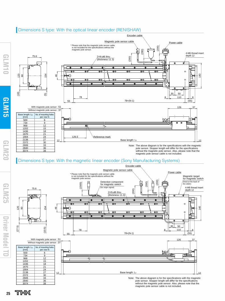
25
Driver Model TD
GLM
20G
LM10
GLM
15G
LM25
Dimensions S type: With the optical linear encoder (RENISHAW)
Power cable
46
78
55 78×(N-1) (55)
110 8
With magnetic pole sensor : 51 37
126.5Base length: L0
5030
154
140
140
(5)
75.6
90120
126
8
(200
)
Reference mark
2×N-ø6 thru (thickness 11.3)
4-M6 thread insert depth 12
(280
)
(
200)
Encoder cable
Magnetic pole sensor cable
(18)
1212
Without magnetic pole sensor : 37
46
30 50110 878
55 78×(N-1) (55)
37With magnetic pole sensor : 51
Base length: L012 12
154
75.6
90120
(27.
5)
(10.
5)
(30
0)
126
8
(150
0)
(200
) (
200)
2×N-ø6 thru (thickness 11.3)
Encoder cable
Power cableMagnetic pole sensor cable
Magnetic target for magnetic switch(fixed at the back of the slider)
Detection component for magnetic switch(for origin signal)
Without magnetic pole sensor : 37
Note: The above diagram is for the specifications with the magnetic pole sensor. Stopper length will differ for the specifications without the magnetic pole sensor. Also, please note that the magnetic pole sensor cable is not included.
Note: The above diagram is for the specifications with the magnetic pole sensor. Stopper length will differ for the specifications without the magnetic pole sensor. Also, please note that the magnetic pole sensor cable is not included.
* Please note that the magnetic pole sensor cable is not included for the specifications without the magnetic pole sensor.
* Please note that the magnetic pole sensor cable is not included for the specifications without the magnetic pole sensor.
4-M6 thread insert depth 12
Base length: L0[mm]
No. of mounting holesper row N
500 6734 9968 12
1202 151436 181670 211904 242138 272372 302606 332840 363074 39
Power cable
46
78
55 78×(N-1) (55)
110 8
With magnetic pole sensor : 51 37
126.5Base length: L0
5030
154
140
140
(5)
75.6
90120
126
8
(200
)
Reference mark
2×N-ø6 thru (thickness 11.3)
4-M6 thread insert depth 12
(280
)
(
200)
Encoder cable
Magnetic pole sensor cable(1
8)
1212
Without magnetic pole sensor : 37
46
30 50110 878
55 78×(N-1) (55)
37With magnetic pole sensor : 51
Base length: L012 12
154
75.6
90120
(27.
5)
(10.
5)
(30
0)
126
8
(150
0)
(200
) (
200)
2×N-ø6 thru (thickness 11.3)
Encoder cable
Power cableMagnetic pole sensor cable
Magnetic target for magnetic switch(fixed at the back of the slider)
Detection component for magnetic switch(for origin signal)
Without magnetic pole sensor : 37
Note: The above diagram is for the specifications with the magnetic pole sensor. Stopper length will differ for the specifications without the magnetic pole sensor. Also, please note that the magnetic pole sensor cable is not included.
Note: The above diagram is for the specifications with the magnetic pole sensor. Stopper length will differ for the specifications without the magnetic pole sensor. Also, please note that the magnetic pole sensor cable is not included.
* Please note that the magnetic pole sensor cable is not included for the specifications without the magnetic pole sensor.
* Please note that the magnetic pole sensor cable is not included for the specifications without the magnetic pole sensor.
4-M6 thread insert depth 12
Base length: L0[mm]
No. of mounting holesper row N
500 6734 9968 12
1202 151436 181670 211904 242138 272372 302606 332840 363074 39
Dimensions S type: With the magnetic linear encoder (Sony Manufacturing Systems)
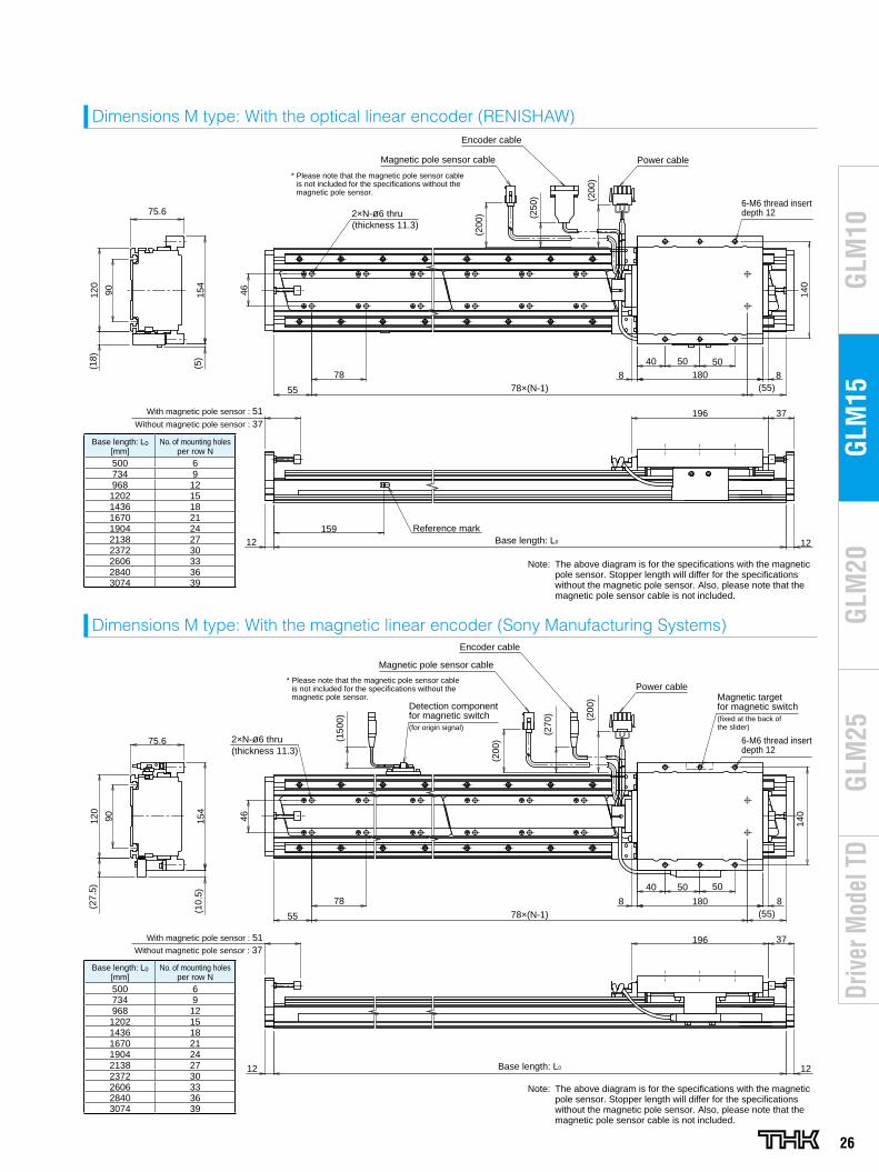
26
GLM
20G
LM10
GLM
15G
LM25
Driv
er M
odel
TD
Dimensions M type: With the optical linear encoder (RENISHAW)
Dimensions M type: With the magnetic linear encoder (Sony Manufacturing Systems)
46
40 50 50180 878
55 78×(N-1) (55)
37With magnetic pole sensor : 51
Base length: L012 12
154
90120
(18)
(5)
159 (
250)
196
8
(200
)
(200
)
75.6
Reference mark
2×N-ø6 thru(thickness 11.3)
Encoder cable
Power cable
Without magnetic pole sensor : 37
46
40 50 50
180 8
55
78
78×(N-1) (55)
37
Base length: L012 12
154
75.6
90120
(27.
5)
(10.
5)
(27
0)
196
8
(
200)
(200
)(150
0)
2×N-ø6 thru(thickness 11.3)
Detection component for magnetic switch(for origin signal)
Power cableMagnetic target for magnetic switch(fixed at the back of the slider)
With magnetic pole sensor : 51Without magnetic pole sensor : 37
Magnetic pole sensor cable
Encoder cable
Magnetic pole sensor cable
140
140
* Please note that the magnetic pole sensor cable is not included for the specifications without the magnetic pole sensor.
* Please note that the magnetic pole sensor cable is not included for the specifications without the magnetic pole sensor.
Note: The above diagram is for the specifications with the magnetic pole sensor. Stopper length will differ for the specifications without the magnetic pole sensor. Also, please note that the magnetic pole sensor cable is not included.
Note: The above diagram is for the specifications with the magnetic pole sensor. Stopper length will differ for the specifications without the magnetic pole sensor. Also, please note that the magnetic pole sensor cable is not included.
6-M6 thread insert depth 12
6-M6 thread insert depth 12
Base length: L0[mm]
No. of mounting holesper row N
500 6734 9968 12
1202 151436 181670 211904 242138 272372 302606 332840 363074 39
46
40 50 50180 878
55 78×(N-1) (55)
37With magnetic pole sensor : 51
Base length: L012 12
154
90120
(18)
(5)
159
(25
0)
196
8
(200
)
(200
)
75.6
Reference mark
2×N-ø6 thru(thickness 11.3)
Encoder cable
Power cable
Without magnetic pole sensor : 37
46
40 50 50
180 8
55
78
78×(N-1) (55)
37
Base length: L012 12
154
75.6
90120
(27.
5)
(10.
5)
(27
0)
196
8
(
200)
(200
)(150
0)
2×N-ø6 thru(thickness 11.3)
Detection component for magnetic switch(for origin signal)
Power cableMagnetic target for magnetic switch(fixed at the back of the slider)
With magnetic pole sensor : 51Without magnetic pole sensor : 37
Magnetic pole sensor cable
Encoder cable
Magnetic pole sensor cable
140
140
* Please note that the magnetic pole sensor cable is not included for the specifications without the magnetic pole sensor.
* Please note that the magnetic pole sensor cable is not included for the specifications without the magnetic pole sensor.
Note: The above diagram is for the specifications with the magnetic pole sensor. Stopper length will differ for the specifications without the magnetic pole sensor. Also, please note that the magnetic pole sensor cable is not included.
Note: The above diagram is for the specifications with the magnetic pole sensor. Stopper length will differ for the specifications without the magnetic pole sensor. Also, please note that the magnetic pole sensor cable is not included.
6-M6 thread insert depth 12
6-M6 thread insert depth 12
Base length: L0[mm]
No. of mounting holesper row N
500 6734 9968 12
1202 151436 181670 211904 242138 272372 302606 332840 363074 39
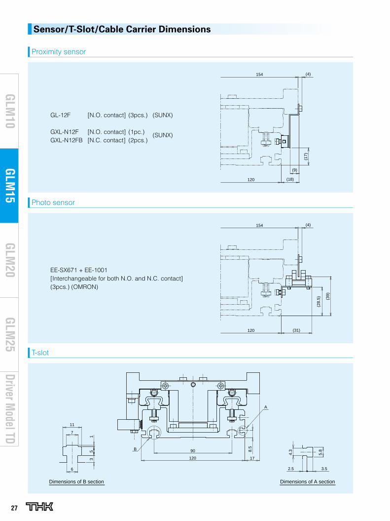
27
Driver Model TD
GLM
20G
LM10
GLM
15G
LM25
Sensor/T-Slot/Cable Carrier Dimensions
Proximity sensor
(17)
(18)
(9)
154 (4)
120
GL-12F [N.O. contact] (3pcs.) (SUNX)
GXL-N12F [N.O. contact] (1pc.) (SUNX)GXL-N12FB [N.C. contact] (2pcs.)
Photo sensor
(31)
(28.
5) (39)
154 (4)
120
T-slot
90
120
8.5
4.3
5.8
2.5
7
5
11
6
17
13
Dimensions of A sectionDimensions of B section
3.5
B
A
EE-SX671 + EE-1001 [Interchangeable for both N.O. and N.C. contact] (3pcs.) (OMRON)
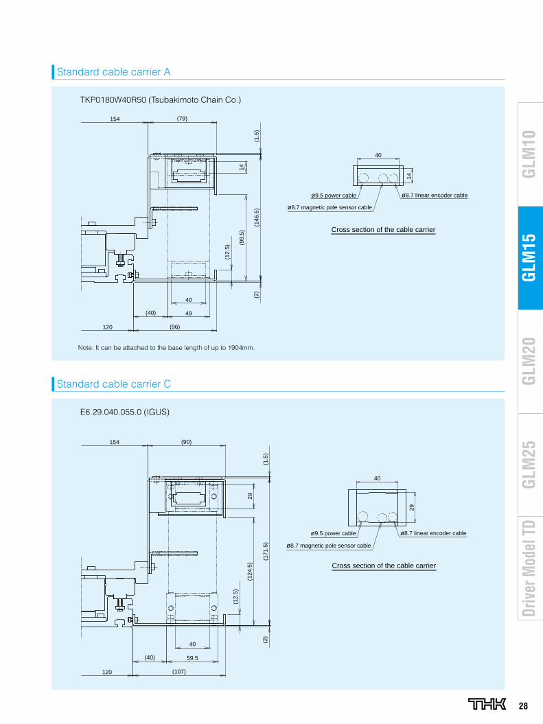
28
GLM
20G
LM10
GLM
15G
LM25
Driv
er M
odel
TD
Standard cable carrier A
(96)
(40) 49
40
(79)
14
(1.5
)
(99.
5)
(146
.5)
(2)
154
120
(12.
5)
40
14
ø9.5 power cable
ø8.7 magnetic pole sensor cable
ø8.7 linear encoder cable
Cross section of the cable carrier
Standard cable carrier C
(107)
(40) 59.5
40 (2)
(171
.5)
(1.5
)
(124
.5)
29
(90)154
120
(12.
5)
40
29
Cross section of the cable carrier
ø9.5 power cable
ø8.7 magnetic pole sensor cable
ø8.7 linear encoder cable
TKP0180W40R50 (Tsubakimoto Chain Co.)
E6.29.040.055.0 (IGUS)
Note: It can be attached to the base length of up to 1904mm.
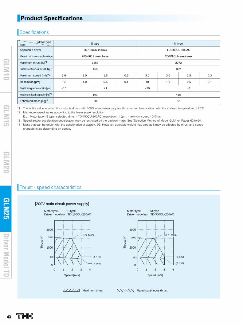
43
Driver Model TD
GLM
20G
LM10
GLM
15G
LM25
Motor typeItem S type M type
Applicable driver TD-150CU-200AC TD-300CU-200AC
Main circuit power supply voltage 200VAC three-phase 200VAC three-phase
Maximum thrust [N]*1 1557 3072
Rated continuous thrust [N]*1 450 892
Maximum speed [m/s]*2 3.0 3.0 1.5 0.3 3.0 3.0 1.5 0.3
Resolution [μm] 10 1.0 0.5 0.1 10 1.0 0.5 0.1
Positioning repeatability [μm] ±10 ±1 ±10 ±1
Maximum load capacity [kg]*3 193 415
Estimated mass [kg]*4 28 52
*1 This is the value in which the motor is driven with 100% of root-mean-square thrust under the condition with the ambient temperature of 20˚C.*2 Maximum speed varies according to the linear scale resolution.
E.g.: Motor type - S type, selected driver - TD-150CU-200AC, resolution - 1.0μm, maximum speed - 3.0m/s*3 Speed and/or acceleration/deceleration may be restricted by the payload mass. See "Selection Method of Model GLM" on Pages 62 to 64.*4 Mass that can be driven with the acceleration of approx. 2G. However, operable weight may vary as it may be affected by thrust and speed
characteristics depending on speed.
Specifications
Thrust - speed characteristics
Product Specifications
Motor type : S typeDriver model no. : TD-150CU-200AC
Motor type : M typeDriver model no. : TD-300CU-200AC
[200V main circuit power supply]
2000
0
1000
0 1 32 40 1 32 4
Speed [m/s] Speed [m/s]
Thr
ust [
N]
Thr
ust [
N]
Maximum thrust Rated continuous thrust
(1.9, 1496)1557
450 (3, 470)
(3, 354)
3072
892
(3, 757)
(3, 932)
(1.8, 2989)
0
4000
2000
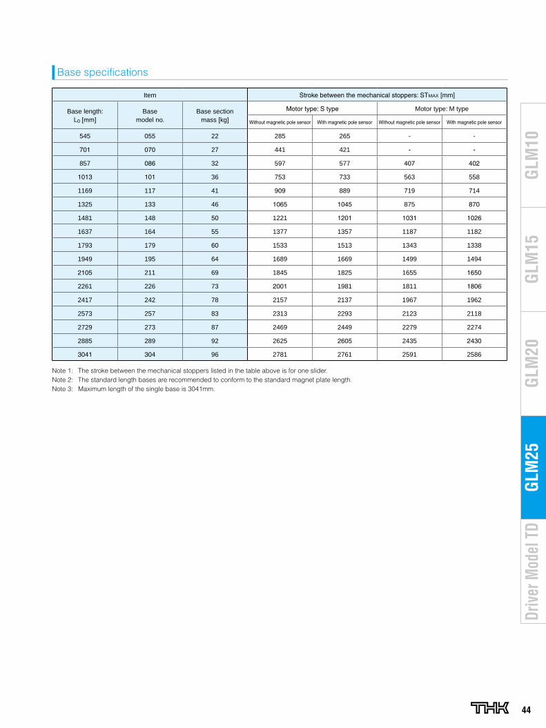
44
GLM
20G
LM10
GLM
15G
LM25
Driv
er M
odel
TD
Item Stroke between the mechanical stoppers: STMAX [mm]
Base length: L0 [mm]
Basemodel no.
Base sectionmass [kg]
Motor type: S type Motor type: M type
Without magnetic pole sensor With magnetic pole sensor Without magnetic pole sensor With magnetic pole sensor
545 055 22 285 265 - -
701 070 27 441 421 - -
857 086 32 597 577 407 402
1013 101 36 753 733 563 558
1169 117 41 909 889 719 714
1325 133 46 1065 1045 875 870
1481 148 50 1221 1201 1031 1026
1637 164 55 1377 1357 1187 1182
1793 179 60 1533 1513 1343 1338
1949 195 64 1689 1669 1499 1494
2105 211 69 1845 1825 1655 1650
2261 226 73 2001 1981 1811 1806
2417 242 78 2157 2137 1967 1962
2573 257 83 2313 2293 2123 2118
2729 273 87 2469 2449 2279 2274
2885 289 92 2625 2605 2435 2430
3041 304 96 2781 2761 2591 2586
Note 1: The stroke between the mechanical stoppers listed in the table above is for one slider. Note 2: The standard length bases are recommended to conform to the standard magnet plate length.Note 3: Maximum length of the single base is 3041mm.
Base specifications
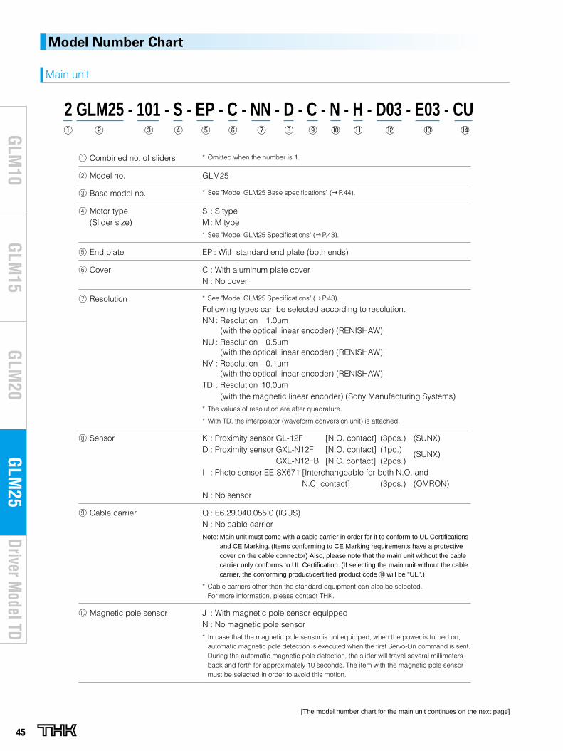
45
Driver Model TD
GLM
20G
LM10
GLM
15G
LM25
Model Number Chart
Main unit
2 GLM25 - 101 - S - EP - C - NN - D - C - N - H - D03 - E03 - CU
[The model number chart for the main unit continues on the next page]
Combined no. of sliders * Omitted when the number is 1.
Model no. GLM25
Base model no. * See "Model GLM25 Base specifications" (g P.44).
Motor type(Slider size)
S : S typeM : M type
* See "Model GLM25 Specifications" (g P.43).
End plate EP : With standard end plate (both ends)
Cover C : With aluminum plate coverN : No cover
Resolution * See "Model GLM25 Specifications" (g P.43).
Following types can be selected according to resolution.NN : Resolution 1.0μm
(with the optical linear encoder) (RENISHAW)NU : Resolution 0.5μm
(with the optical linear encoder) (RENISHAW)NV : Resolution 0.1μm
(with the optical linear encoder) (RENISHAW)TD : Resolution 10.0μm
(with the magnetic linear encoder) (Sony Manufacturing Systems)
* The values of resolution are after quadrature.
* With TD, the interpolator (waveform conversion unit) is attached.
Sensor K : Proximity sensor GL-12F [N.O. contact] (3pcs.) (SUNX)D : Proximity sensor GXL-N12F [N.O. contact] (1pc.) (SUNX)
GXL-N12FB [N.C. contact] (2pcs.)I : Photo sensor EE-SX671 [Interchangeable for both N.O. and
N.C. contact] (3pcs.) (OMRON)N : No sensor
Cable carrier Q : E6.29.040.055.0 (IGUS)N : No cable carrier
Note: Main unit must come with a cable carrier in order for it to conform to UL Certifications and CE Marking. (Items conforming to CE Marking requirements have a protective cover on the cable connector) Also, please note that the main unit without the cable carrier only conforms to UL Certification. (If selecting the main unit without the cable carrier, the conforming product/certified product code will be "UL".)
* Cable carriers other than the standard equipment can also be selected. For more information, please contact THK.
Magnetic pole sensor J : With magnetic pole sensor equippedN : No magnetic pole sensor
* In case that the magnetic pole sensor is not equipped, when the power is turned on, automatic magnetic pole detection is executed when the first Servo-On command is sent. During the automatic magnetic pole detection, the slider will travel several millimeters back and forth for approximately 10 seconds. The item with the magnetic pole sensor must be selected in order to avoid this motion.
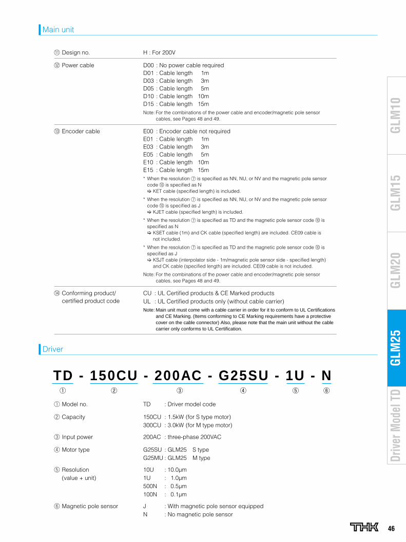
46
GLM
20G
LM10
GLM
15G
LM25
Driv
er M
odel
TD
Main unit
TD - 150CU - 200AC - G25SU - 1U - N
Driver
Design no. H : For 200V
Power cable D00 : No power cable requiredD01 : Cable length 1mD03 : Cable length 3mD05 : Cable length 5mD10 : Cable length 10mD15 : Cable length 15mNote: For the combinations of the power cable and encoder/magnetic pole sensor
cables, see Pages 48 and 49.
Encoder cable E00 : Encoder cable not requiredE01 : Cable length 1mE03 : Cable length 3mE05 : Cable length 5mE10 : Cable length 10mE15 : Cable length 15m* When the resolution is specified as NN, NU, or NV and the magnetic pole sensor
code is specified as N [ KET cable (specified length) is included.
* When the resolution is specified as NN, NU, or NV and the magnetic pole sensor code is specified as J [ KJET cable (specified length) is included.
* When the resolution is specified as TD and the magnetic pole sensor code is specified as N [ KSET cable (1m) and CK cable (specified length) are included. CE09 cable is
not included.
* When the resolution is specified as TD and the magnetic pole sensor code is specified as J [ KSJT cable (interpolator side - 1m/magnetic pole sensor side - specified length)
and CK cable (specified length) are included. CE09 cable is not included.
Note: For the combinations of the power cable and encoder/magnetic pole sensor cables, see Pages 48 and 49.
Conforming product/ certified product code
CU : UL Certified products & CE Marked productsUL : UL Certified products only (without cable carrier) Note: Main unit must come with a cable carrier in order for it to conform to UL Certifications
and CE Marking. (Items conforming to CE Marking requirements have a protective cover on the cable connector) Also, please note that the main unit without the cable carrier only conforms to UL Certification.
Model no. TD : Driver model code
Capacity 150CU : 1.5kW (for S type motor)300CU : 3.0kW (for M type motor)
Input power 200AC : three-phase 200VAC
Motor type G25SU : GLM25 S typeG25MU : GLM25 M type
Resolution(value + unit)
10U : 10.0μm1U : 1.0μm500N : 0.5μm100N : 0.1μm
Magnetic pole sensor J : With magnetic pole sensor equippedN : No magnetic pole sensor
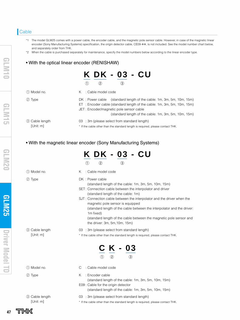
47
Driver Model TD
GLM
20G
LM10
GLM
15G
LM25
K DK - 03 - CU
• With the optical linear encoder (RENISHAW)
Cable
• With the magnetic linear encoder (Sony Manufacturing Systems)
K DK - 03 - CU
*1 The model GLM25 comes with a power cable, the encoder cable, and the magnetic pole sensor cable. However, in case of the magnetic linear encoder (Sony Manufacturing Systems) specification, the origin detector cable, CE09-**, is not included. See the model number chart below, and separately order from THK.
*2 When the cable is purchased separately for maintenance, specify the model numbers below according to the linear encoder type.
C K - 03
Model no. K : Cable model code
Type DK : Power cable (standard length of the cable: 1m, 3m, 5m, 10m, 15m)ET : Encoder cable (standard length of the cable: 1m, 3m, 5m, 10m, 15m)JET : Encoder/magnetic pole sensor cable
(standard length of the cable: 1m, 3m, 5m, 10m, 15m)
Cable length[Unit: m]
03 : 3m (please select from standard length)
* If the cable other than the standard length is required, please contact THK.
Model no. K : Cable model code
Type DK : Power cable (standard length of the cable: 1m, 3m, 5m, 10m, 15m)
SET : Connection cable between the interpolator and driver (standard length of the cable: 1m)
SJT : Connection cable between the interpolator and the driver when the magnetic pole sensor is equipped (standard length of the cable between the interpolator and the driver: 1m fixed) (standard length of the cable between the magnetic pole sensor and the driver: 3m, 5m,10m, 15m)
Cable length[Unit: m]
03 : 3m (please select from standard length)
* If the cable other than the standard length is required, please contact THK.
Model no. C : Cable model code
Type K : Encoder cable (standard length of the cable: 1m, 3m, 5m, 10m, 15m)
E09 : Cable for the origin detector (standard length of the cable: 1m, 3m, 5m, 10m, 15m)
Cable length[Unit: m]
03 : 3m (please select from standard length)
* If the cable other than the standard length is required, please contact THK.
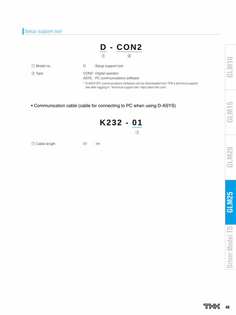
48
GLM
20G
LM10
GLM
15G
LM25
Driv
er M
odel
TD
Model no. D : Setup support tool
Type CON2 : Digital operatorASYS : PC communications software
* D-ASYS (PC communications software) can be downloaded from THK's technical support site after logging in. Technical support site: https://tech.thk.com/
Cable length 01 : 1m
Setup support tool
D - CON2
K232 - 01
• Communication cable (cable for connecting to PC when using D-ASYS)
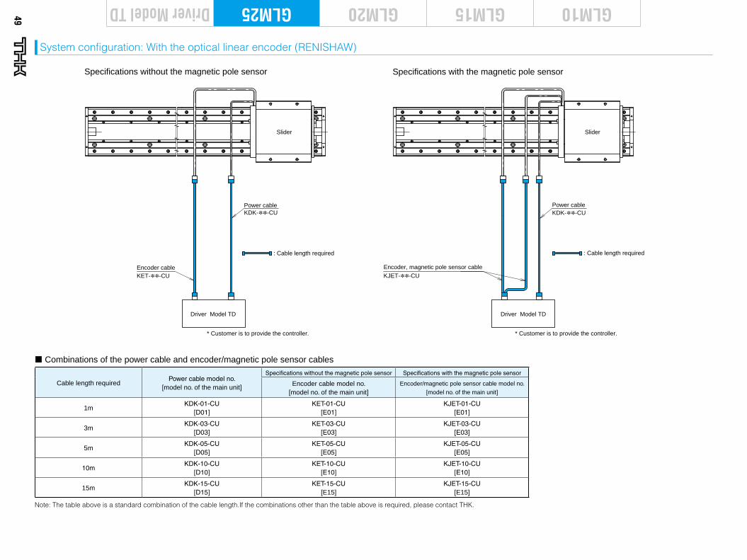
Driver Model TD
Encoder, magnetic pole sensor cable
Slider
KDK-∗∗-CUPower cable
KJET-∗∗-CU
Specifications without the magnetic pole sensor Specifications with the magnetic pole sensor
Driver Model TD
Encoder cable
Slider
KDK-∗∗-CUPower cable
KET-∗∗-CU
* Customer is to provide the controller. * Customer is to provide the controller.
: Cable length required : Cable length required
Cable length requiredPower cable model no.
[model no. of the main unit]
Specifications without the magnetic pole sensor Specifications with the magnetic pole sensor
Encoder cable model no. [model no. of the main unit]
Encoder/magnetic pole sensor cable model no. [model no. of the main unit]
1mKDK-01-CU
[D01]KET-01-CU
[E01]KJET-01-CU
[E01]
3mKDK-03-CU
[D03]KET-03-CU
[E03]KJET-03-CU
[E03]
5mKDK-05-CU
[D05]KET-05-CU
[E05]KJET-05-CU
[E05]
10mKDK-10-CU
[D10]KET-10-CU
[E10]KJET-10-CU
[E10]
15mKDK-15-CU
[D15]KET-15-CU
[E15]KJET-15-CU
[E15]
Note: The table above is a standard combination of the cable length.If the combinations other than the table above is required, please contact THK.
¢ Combinations of the power cable and encoder/magnetic pole sensor cables
System configuration: With the optical linear encoder (RENISHAW)
49
Driver Model TD GLM20 GLM10GLM15GLM25
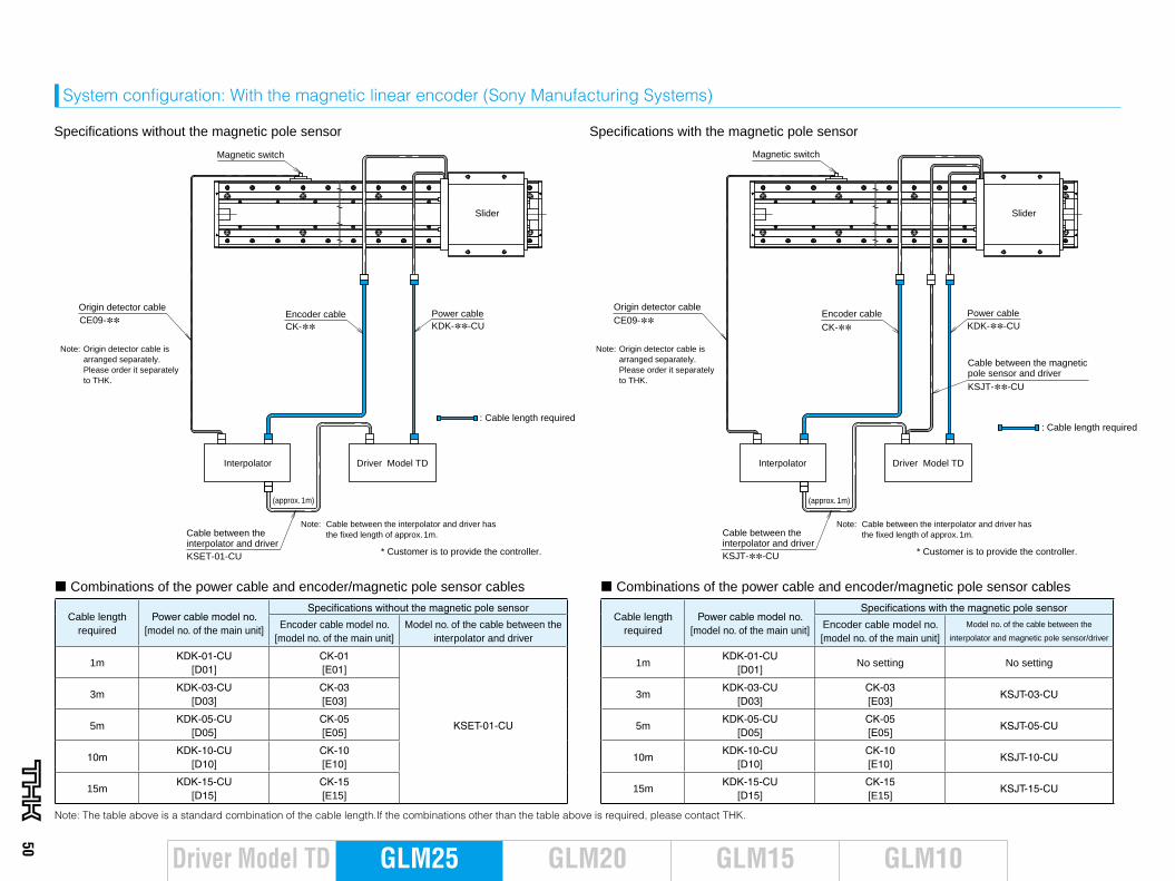
System configuration: With the magnetic linear encoder (Sony Manufacturing Systems)
Note: Origin detector cable is arranged separately. Please order it separately to THK.
Note: Origin detector cable is arranged separately. Please order it separately to THK.
Driver Model TD
Slider
Interpolator
Specifications without the magnetic pole sensor
Origin detector cable
KDK-∗∗-CUEncoder cable Power cableCK-∗∗CE09-∗∗
Magnetic switch
(approx. 1m)
Driver Model TD
Slider
Interpolator
Origin detector cable
KDK-∗∗-CUEncoder cable Power cable
CK-∗∗CE09-∗∗
Magnetic switch
(approx. 1m)
Specifications with the magnetic pole sensor
KSJT-∗∗-CU
: Cable length required: Cable length required
Cable between the interpolator and driver
Cable between the magnetic pole sensor and driver
KSET-01-CU * Customer is to provide the controller.
Note: Cable between the interpolator and driver has the fixed length of approx. 1m.
* Customer is to provide the controller.
Note: Cable between the interpolator and driver has the fixed length of approx. 1m. Cable between the
interpolator and driverKSJT-∗∗-CU
Cable length required
Power cable model no. [model no. of the main unit]
Specifications without the magnetic pole sensor
Encoder cable model no. [model no. of the main unit]
Model no. of the cable between the interpolator and driver
1mKDK-01-CU
[D01]CK-01 [E01]
KSET-01-CU
3mKDK-03-CU
[D03]CK-03 [E03]
5mKDK-05-CU
[D05]CK-05 [E05]
10mKDK-10-CU
[D10]CK-10 [E10]
15mKDK-15-CU
[D15]CK-15 [E15]
Note: The table above is a standard combination of the cable length.If the combinations other than the table above is required, please contact THK.
Cable length required
Power cable model no. [model no. of the main unit]
Specifications with the magnetic pole sensor
Encoder cable model no. [model no. of the main unit]
Model no. of the cable between the
interpolator and magnetic pole sensor/driver
1mKDK-01-CU
[D01]No setting No setting
3mKDK-03-CU
[D03]CK-03 [E03]
KSJT-03-CU
5mKDK-05-CU
[D05]CK-05 [E05]
KSJT-05-CU
10mKDK-10-CU
[D10]CK-10 [E10]
KSJT-10-CU
15mKDK-15-CU
[D15]CK-15 [E15]
KSJT-15-CU
¢ Combinations of the power cable and encoder/magnetic pole sensor cables ¢ Combinations of the power cable and encoder/magnetic pole sensor cables
50
GLM20 GLM10GLM15GLM25Driver Model TD
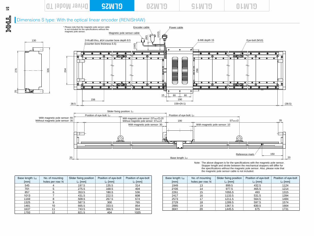
51
Driver Model TD GLM20 GLM10GLM15GLM25
Base length: L0
[mm]No. of mounting holes per row: N
Slider fixing positionL1 [mm]
Position of eye-bolt L2 [mm]
Position of eye-boltL3 [mm]
545 4 197.5 135.5 314701 5 275.5 168.5 404857 6 353.5 180.5 536
1013 7 431.5 222.5 6081169 8 509.5 267.5 6741325 9 587.5 300 7651481 10 665.5 333.5 8541637 11 743.5 366.5 9441793 12 821.5 404 1025
Dimensions S type: With the optical linear encoder (RENISHAW)
Base length: L0
[mm]No. of mounting holes per row: N
Slider fixing positionL1 [mm]
Position of eye-bolt L2 [mm]
Position of eye-bolt L3 [mm]
1949 13 899.5 432.5 11242105 14 977.5 465.5 12142261 15 1055.5 493 13152417 16 1133.5 531.5 13942573 17 1211.5 564.5 14842729 18 1289.5 597.5 15742885 19 1367.5 630.5 16643041 20 1445.5 675 1731
326
130
276
25
156
204
156×(N-1) (38.5)
Without magnetic pole sensor: 35 190 35
Position of eye-bolt: L2 Position of eye-bolt: L3
Slider fixing position: L1
38.5
150
Base length: L0
Eye-bolt (M10)2×N-ø9 thru, ø14 counter bore depth 8.5(counter-bore thickness 6.5)
Reference mark
80 80
190
With magnetic pole sensor: 30 With magnetic pole sensor: 10
(160
) (
80)
(410
)20 20
15
With magnetic pole sensor: (STMAX/2)-20Without magnetic pole sensor: STMAX/2
With magnetic pole sensor: 55
Magnetic pole sensor cable
Encoder cable Power cable
296
6-M6 depth 15
Note: The above diagram is for the specifications with the magnetic pole sensor. Stopper length and stroke between the mechanical stoppers will differ for the specifications without the magnetic pole sensor. Also, please note that the magnetic pole sensor cable is not included.
* Please note that the magnetic pole sensor cable is not included for the specifications without the magnetic pole sensor.
STMAX/2
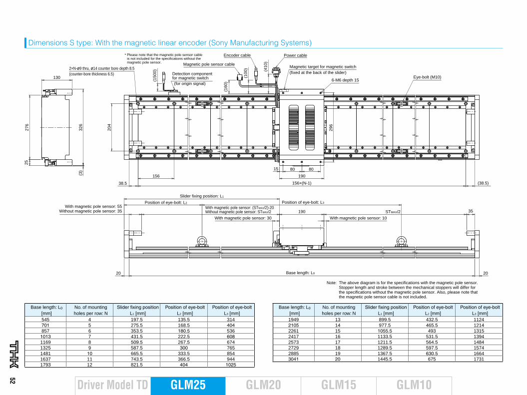
52
GLM20 GLM10GLM15GLM25Driver Model TD
Dimensions S type: With the magnetic linear encoder (Sony Manufacturing Systems)
326
130
276
25
156
204
156×(N-1) (38.5)38.5
20Base length: L020
15 80 80
190
(160
) (
100)
(410
)
(150
0)
(3)
With magnetic pole sensor: (STMAX/2)-20Without magnetic pole sensor: STMAX/2 190
Position of eye-bolt: L3Position of eye-bolt: L2
Slider fixing position: L1
(for origin signal)
Detection component for magnetic switch
Magnetic target for magnetic switch(fixed at the back of the slider)
35
296
Note: The above diagram is for the specifications with the magnetic pole sensor. Stopper length and stroke between the mechanical stoppers will differ for the specifications without the magnetic pole sensor. Also, please note that the magnetic pole sensor cable is not included.
* Please note that the magnetic pole sensor cable is not included for the specifications without the magnetic pole sensor. Magnetic pole sensor cable
Encoder cable Power cable
Eye-bolt (M10)6-M6 depth 15
2×N-ø9 thru, ø14 counter bore depth 8.5(counter-bore thickness 6.5)
Without magnetic pole sensor: 35With magnetic pole sensor: 55
With magnetic pole sensor: 30 With magnetic pole sensor: 10
STMAX/2
Base length: L0 [mm]
No. of mounting holes per row: N
Slider fixing positionL1 [mm]
Position of eye-bolt L2 [mm]
Position of eye-bolt L3 [mm]
545 4 197.5 135.5 314701 5 275.5 168.5 404857 6 353.5 180.5 536
1013 7 431.5 222.5 6081169 8 509.5 267.5 6741325 9 587.5 300 7651481 10 665.5 333.5 8541637 11 743.5 366.5 9441793 12 821.5 404 1025
Base length: L0
[mm]No. of mounting holes per row: N
Slider fixing positionL1 [mm]
Position of eye-bolt L2 [mm]
Position of eye-bolt L3 [mm]
1949 13 899.5 432.5 11242105 14 977.5 465.5 12142261 15 1055.5 493 13152417 16 1133.5 531.5 13942573 17 1211.5 564.5 14842729 18 1289.5 597.5 15742885 19 1367.5 630.5 16643041 20 1445.5 675 1731
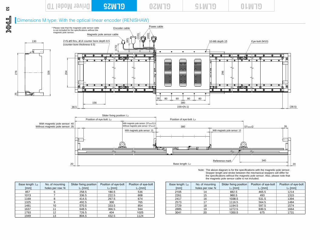
53
Driver Model TD GLM20 GLM10GLM15GLM25
Dimensions M type: With the optical linear encoder (RENISHAW)
Base length: L0
[mm]No. of mounting holes per row: N
Slider fixing positionL1 [mm]
Position of eye-boltL2 [mm]
Position of eye-boltL3 [mm]
857 6 258.5 180.5 5361013 7 336.5 222.5 6081169 8 414.5 267.5 6741325 9 492.5 300 7651481 10 570.5 333.5 8541637 11 648.5 366.5 9441793 12 726.5 404 10251949 13 804.5 432.5 1124
Base length: L0
[mm]No. of mounting holes per row: N
Slider fixing positionL1 [mm]
Position of eye-boltL2 [mm]
Position of eye-boltL3 [mm]
2105 14 882.5 465.5 12142261 15 960.5 493 13152417 16 1038.5 531.5 13942573 17 1116.5 564.5 14842729 18 1194.5 597.5 15742885 19 1272.5 630.5 16643041 20 1350.5 675 1731
Note: The above diagram is for the specifications with the magnetic pole sensor. Stopper length and stroke between the mechanical stoppers will differ for the specifications without the magnetic pole sensor. Also, please note that the magnetic pole sensor cable is not included.
STMAX/2Without magnetic pole sensor: 35With magnetic pole sensor: 40
156
204
326
130
276
25
30 80 80 80 80
380
156×(N-1) (38.5)
380 35
Position of eye-bolt: L3Position of eye-bolt: L2
Slider fixing position: L1
38.5
34020Base length: L020
Reference mark
(170
) (8
0)
(
400)
(
220)
With magnetic pole sensor: 15 With magnetic pole sensor: 10
296
* Please note that the magnetic pole sensor cable is not included for the specifications without the magnetic pole sensor.
Magnetic pole sensor cable
Encoder cablePower cable
Eye-bolt (M10)10-M6 depth 152×N-ø9 thru, ø14 counter bore depth 8.5(counter-bore thickness 6.5)
With magnetic pole sensor: (STMAX/2)-5Without magnetic pole sensor: STMAX/2
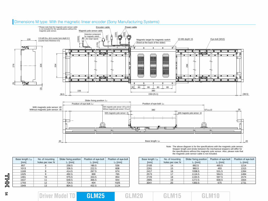
54
GLM20 GLM10GLM15GLM25Driver Model TD
Dimensions M type: With the magnetic linear encoder (Sony Manufacturing Systems)
Base length: L0
[mm]No. of mounting holes per row: N
Slider fixing positionL1 [mm]
Position of eye-boltL2 [mm]
Position of eye-boltL3 [mm]
857 6 258.5 180.5 5361013 7 336.5 222.5 6081169 8 414.5 267.5 6741325 9 492.5 300 7651481 10 570.5 333.5 8541637 11 648.5 366.5 9441793 12 726.5 404 10251949 13 804.5 432.5 1124
Base length: L0
[mm]No. of mounting holes per row: N
Slider fixing positionL1 [mm]
Position of eye-boltL2 [mm]
Position of eye-boltL3 [mm]
2105 14 882.5 465.5 12142261 15 960.5 493 13152417 16 1038.5 531.5 13942573 17 1116.5 564.5 14842729 18 1194.5 597.5 15742885 19 1272.5 630.5 16643041 20 1350.5 675 1731
STMAX/2
Note: The above diagram is for the specifications with the magnetic pole sensor. Stopper length and stroke between the mechanical stoppers will differ for the specifications without the magnetic pole sensor. Also, please note that the magnetic pole sensor cable is not included.
Without magnetic pole sensor: 35With magnetic pole sensor: 40
156
204
326
130
276
25
30 80 80 80 80
380
156×(N-1) (38.5)38.5
(170
) (1
00)
(
400)
(
220)
(150
0)
(3)
380 35
Position of eye-bolt: L3Position of eye-bolt: L2
Slider fixing position: L1
Base length: L020 20
296
* Please note that the magnetic pole sensor cable is not included for the specifications without the magnetic pole sensor. Magnetic pole sensor cable
Encoder cable Power cable
Eye-bolt (M10)10-M6 depth 152×N-ø9 thru, ø14 counter bore depth 8.5(counter-bore thickness 6.5)
(for origin signal)
Detection component for magnetic switch
Magnetic target for magnetic switch(fixed at the back of the slider)
With magnetic pole sensor: (STMAX/2)-5Without magnetic pole sensor: STMAX/2
With magnetic pole sensor: 15 With magnetic pole sensor: 10
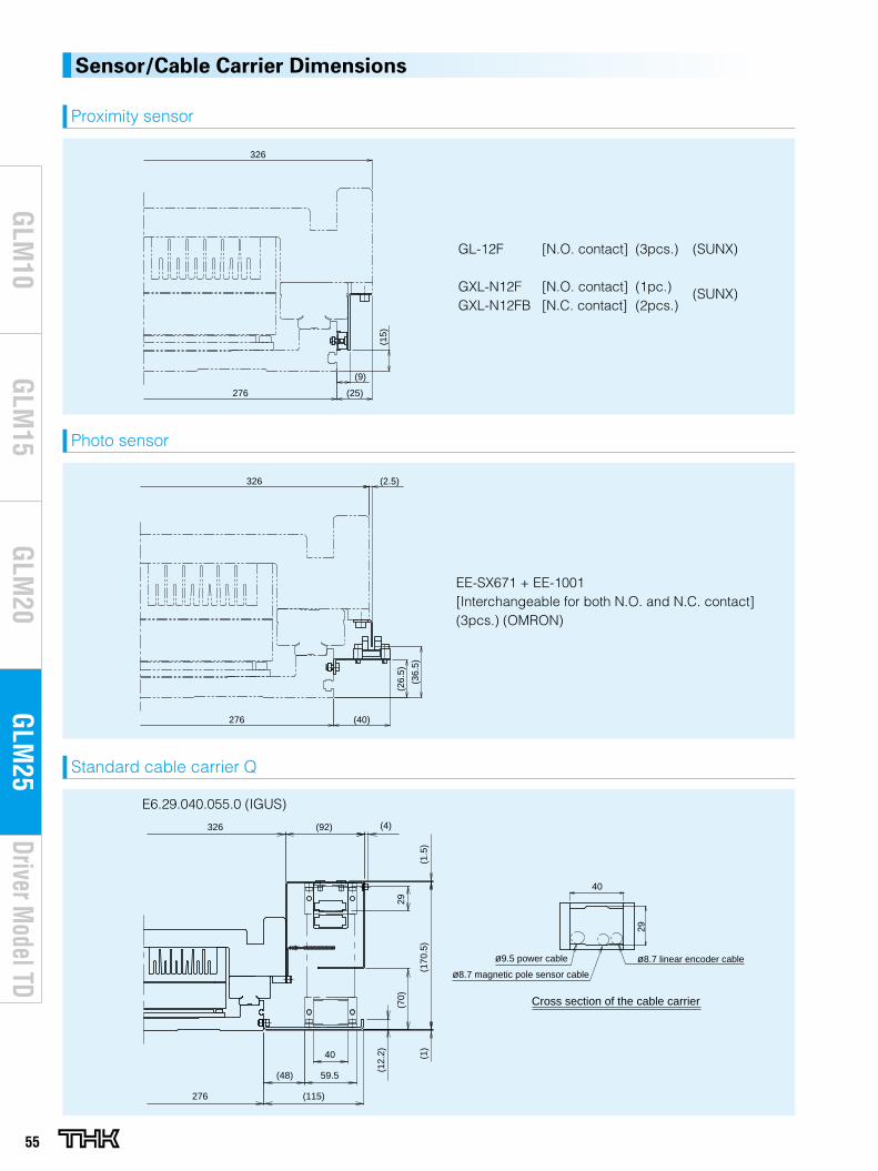
55
Driver Model TD
GLM
20G
LM10
GLM
15G
LM25
Proximity sensor
GL-12F [N.O. contact] (3pcs.) (SUNX)
GXL-N12F [N.O. contact] (1pc.) (SUNX)GXL-N12FB [N.C. contact] (2pcs.)
Photo sensor
EE-SX671 + EE-1001[Interchangeable for both N.O. and N.C. contact] (3pcs.) (OMRON)
Standard cable carrier Q
E6.29.040.055.0 (IGUS)
Sensor/Cable Carrier Dimensions
(25)
(9)(1
5)(40)
(2.5)
(36.
5)
(26.
5)
326
276 276
326
(25)
(9)
(15)
(40)
(2.5)
(36.
5)
(26.
5)
326
276 276
326
(115)
(48) 59.5
40
(92)
(1)
(170
.5)
(1.5
)
(4)
(70)
29
326
276
(12.
2)
40
29
ø9.5 power cable
ø8.7 magnetic pole sensor cable
ø8.7 linear encoder cable
Cross section of the cable carrier
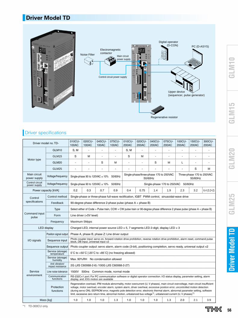
56
GLM
20G
LM10
GLM
15G
LM25
Driv
er M
odel
TD
Noise Filter
Electromagneticcontactor
Main circuit power supply
Control circuit power supply
Regenerative resistor
Digital operator(D-CON) PC (D-ASYS)
Upper device(sequencer, pulse generator)
Driver Model TD
Driver model no. TD-010CU-100AC
020CU-100AC
045CU-100AC
075CU-100AC
010CU-200AC
020CU-200AC
045CU-200AC
075CU-200AC
100CU-200AC
150CU-200AC
300CU-200AC
Motor type
GLM10 S, M - - - S, M - - - - - -
GLM15 S M - - S M - - - - -
GLM20 - - S M - - S M L - -
GLM25 - - - - - - - - - S M
Main circuit power supply
Voltage/frequency Single-phase 90 to 120VAC ± 10% 50/60HzSingle-phase/three-phase 170 to 250VAC
50/60HzThree-phase 170 to 250VAC
50/60Hz
Control circuit power supply Voltage/frequency Single-phase 90 to 120VAC ± 10% 50/60Hz Single-phase 170 to 250VAC 50/60Hz
Power capacity [kVA] 0.2 0.3 0.7 0.9 0.4 0.75 1.4 1.9 2.3 3.2 6.4 (3.2×2)
Control specifications
Control method Single-phase or three-phase full-wave rectification, IGBT PWM control, sinusoidal-wave drive
Feedback 90-degree phase difference 2-phase pulse (phase A + phase B)
Command input pulse
Type Select either of Code + Pulse train, CCW + CW pulse train or 90-degree phase difference 2 phase pulse (phase A + phase B)
Form Line driver (+5V level)
Frequency Maximum 5Mpps
LED display Charged LED, internal power source LED × 5, 7 segments LED 2-digit, display LED × 3
I/O signals
Position signal output Phase A, phase B, phase Z: Line driver output
Sequence input Photo coupler input: servo on, forward rotation drive prohibition, reverse rotation drive prohibition, alarm reset, command pulse block, DB input, universal input ×2
Sequence output Photo coupler output: servo alarm, alarm code (3-bit), positioning completion, servo ready, universal output ×2
Service environment
Service (storage) temperature 0˚C to +50˚C [-20˚C to +85˚C] (no freezing allowed)
Service (storage) humidity Max. 90%RH No condensation allowed
Anti vibration/ impact resistance 2G (JIS C60068-2-6) /100G (JIS C60068-2-27)
Line noise tolerance 1500V 500ns Common mode, normal mode
Communication functions
RS-232C×1 port: For PC communication software or digital operator connection. I/O status display, parameter setting, alarm display, and JOG motion are available
Protection functions
Regeneration overload, IPM module abnormality, motor overcurrent (U, V phases), main circuit overvoltage, main circuit insufficient voltage, motor overload, encoder alarm, system alarm, driver overheat, excessive position error, uncontrolled motion detection (during servo ON), EEPROM error, magnetic pole detection error, electronic thermal alarm, abnormal parameter setting, software limit, excessive zero return time, abnormal motion, unbalanced bus voltage*1, unbalanced current (U, V phases)*1
Mass [kg] 1.0 1.0 1.0 1.3 1.0 1.0 1.0 1.3 2.0 2.1 3.9
Driver specifications
*1 TD-300CU only.
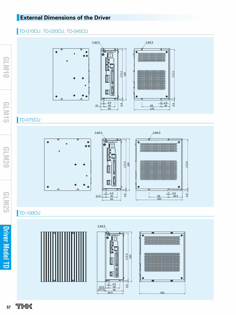
57
Driver Model TD
GLM
20G
LM10
GLM
15G
LM25
External Dimensions of the Driver
TD-010CU, TD-020CU, TD-045CU
TD-075CU
TD-100CU
6010
4.568 30
172.
53.
8
172.
53.
8
125
4.540
180
2-ø4.5 2-ø4.5
6512.5
4.5
16268 48.5
172.
53.
8
172.
53.
8 4.5
180
2-ø4.5 2-ø4.5
40
6512.5
4.5
165(29.5)
172.
53.
8
40
180
2-ø4.5
94.5
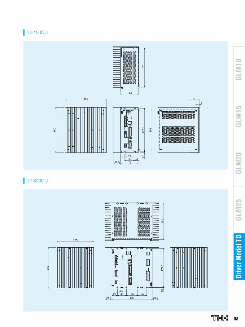
58
GLM
20G
LM10
GLM
15G
LM25
Driv
er M
odel
TD
TD-150CU
TD-300CU
165
180
1640
172.
53.
8
72
168
4
41
71.5
157
29.5
4.5
29.525 40 50 40
180 29.5
180
165
172.
538
161
4.5
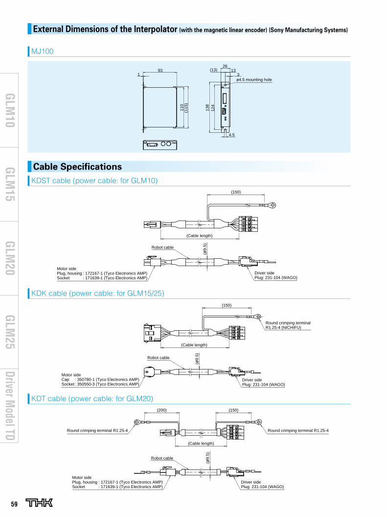
(200) (150)
(Cable length)
(ø9.
5)
Motor sidePlug, housing : 172167-1 (Tyco Electronics AMP)Socket : 171639-1 (Tyco Electronics AMP)
Driver sidePlug: 231-104 (WAGO)
Robot cable
Round crimping terminal R1.25-4 Round crimping terminal R1.25-4
FGPE
FGPE
Motor sideCap : 350780-1 (Tyco Electronics AMP)Socket : 350550-3 (Tyco Electronics AMP)
(Cable length)
Driver sidePlug: 231-104 (WAGO)
(150)
Round crimping terminalR1.25-4 (NICHIFU)
(ø9.
5)Robot cable
FG
59
Driver Model TD
GLM
20G
LM10
GLM
15G
LM25
External Dimensions of the Interpolator (with the magnetic linear encoder) (Sony Manufacturing Systems)
MJ100
110
(115
)
93 (13) 133
26
124
138
4.5
1ø4.5 mounting hole
Cable SpecificationsKDST cable (power cable: for GLM10)
KDK cable (power cable: for GLM15/25)
KDT cable (power cable: for GLM20)
Motor sidePlug, housing : 172167-1 (Tyco Electronics AMP)Socket : 171639-1 (Tyco Electronics AMP)
Driver sidePlug: 231-104 (WAGO)
(ø9.
5)
(Cable length)
Robot cable
(150)
FG
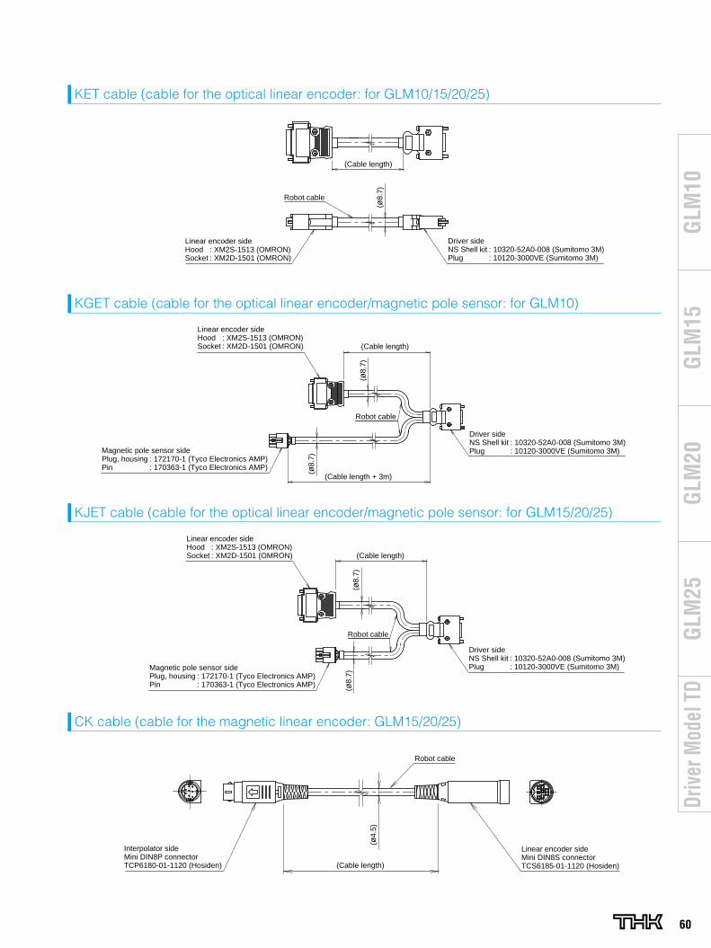
(Cable length)
Linear encoder sideHood : XM2S-1513 (OMRON) Socket : XM2D-1501 (OMRON)
Driver sideNS Shell kit : 10320-52A0-008 (Sumitomo 3M) Plug : 10120-3000VE (Sumitomo 3M)
(ø8.
7)
Robot cable
Linear encoder sideHood : XM2S-1513 (OMRON) Socket : XM2D-1501 (OMRON) (Cable length)
(ø8.
7)
Driver sideNS Shell kit : 10320-52A0-008 (Sumitomo 3M) Plug : 10120-3000VE (Sumitomo 3M)
Robot cable
Magnetic pole sensor sidePlug, housing : 172170-1 (Tyco Electronics AMP)Pin : 170363-1 (Tyco Electronics AMP)
(ø8.
7)
(Cable length + 3m)
60
GLM
20G
LM10
GLM
15G
LM25
Driv
er M
odel
TD
KET cable (cable for the optical linear encoder: for GLM10/15/20/25)
KGET cable (cable for the optical linear encoder/magnetic pole sensor: for GLM10)
Linear encoder sideHood : XM2S-1513 (OMRON)Socket : XM2D-1501 (OMRON)
Magnetic pole sensor sidePlug, housing : 172170-1 (Tyco Electronics AMP)Pin : 170363-1 (Tyco Electronics AMP)
Robot cable
Driver sideNS Shell kit : 10320-52A0-008 (Sumitomo 3M) Plug : 10120-3000VE (Sumitomo 3M)
(ø8.
7)(ø
8.7)
(Cable length)
KJET cable (cable for the optical linear encoder/magnetic pole sensor: for GLM15/20/25)
(ø4.
5)
(Cable length)
Linear encoder sideMini DIN8S connector TCS6185-01-1120 (Hosiden)
Interpolator sideMini DIN8P connector TCP6180-01-1120 (Hosiden)
Robot cable
CK cable (cable for the magnetic linear encoder: GLM15/20/25)
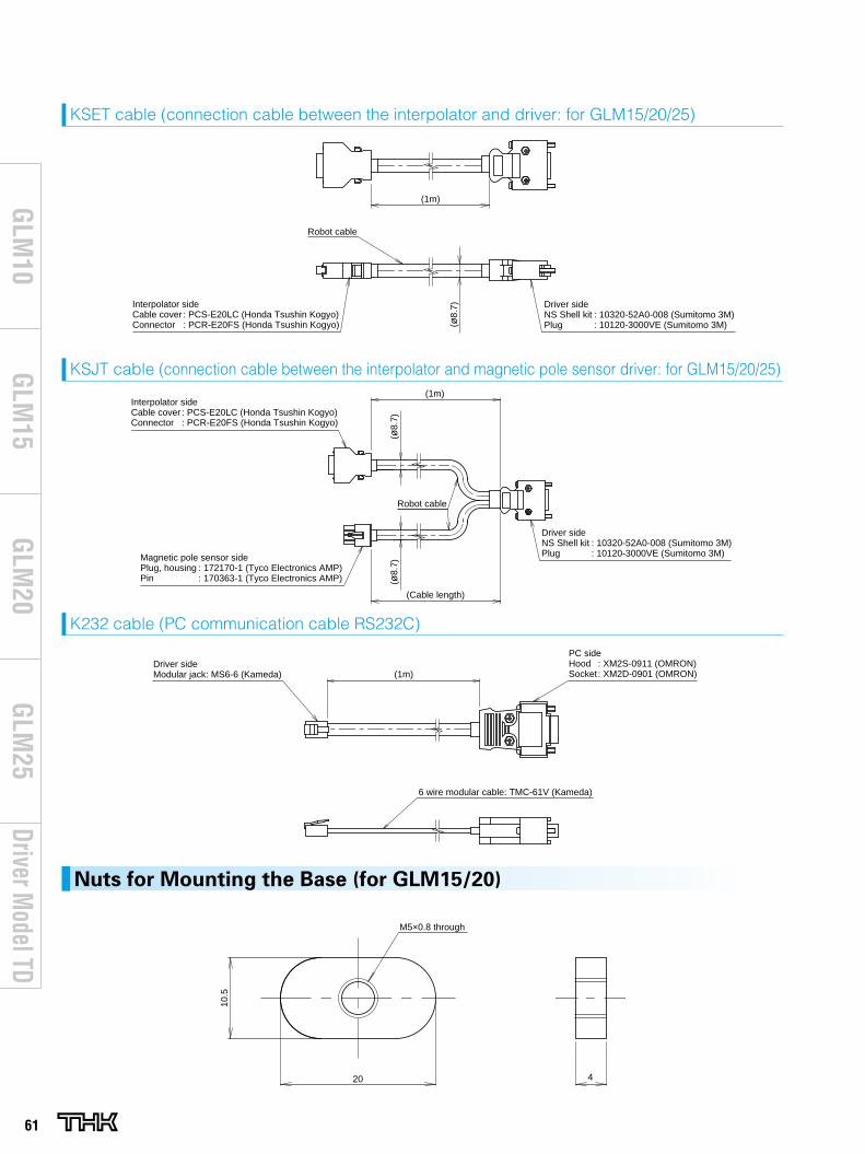
(1m)
Robot cable
Interpolator sideCable cover : PCS-E20LC (Honda Tsushin Kogyo)Connector : PCR-E20FS (Honda Tsushin Kogyo)
Driver sideNS Shell kit : 10320-52A0-008 (Sumitomo 3M)Plug : 10120-3000VE (Sumitomo 3M)(ø
8.7)
Interpolator sideCable cover : PCS-E20LC (Honda Tsushin Kogyo)Connector : PCR-E20FS (Honda Tsushin Kogyo)
(1m)(ø
8.7)
Magnetic pole sensor sidePlug, housing : 172170-1 (Tyco Electronics AMP)Pin : 170363-1 (Tyco Electronics AMP)
Driver sideNS Shell kit : 10320-52A0-008 (Sumitomo 3M) Plug : 10120-3000VE (Sumitomo 3M)
(ø8.
7)
Robot cable
(Cable length)
Driver sideModular jack: MS6-6 (Kameda)
PC sideHood : XM2S-0911 (OMRON) Socket : XM2D-0901 (OMRON)(1m)
6 wire modular cable: TMC-61V (Kameda)
61
Driver Model TD
GLM
20G
LM10
GLM
15G
LM25
KSET cable (connection cable between the interpolator and driver: for GLM15/20/25)
KSJT cable (connection cable between the interpolator and magnetic pole sensor driver: for GLM15/20/25)
K232 cable (PC communication cable RS232C)
10.5
20 4
M5×0.8 through
Nuts for Mounting the Base (for GLM15/20)
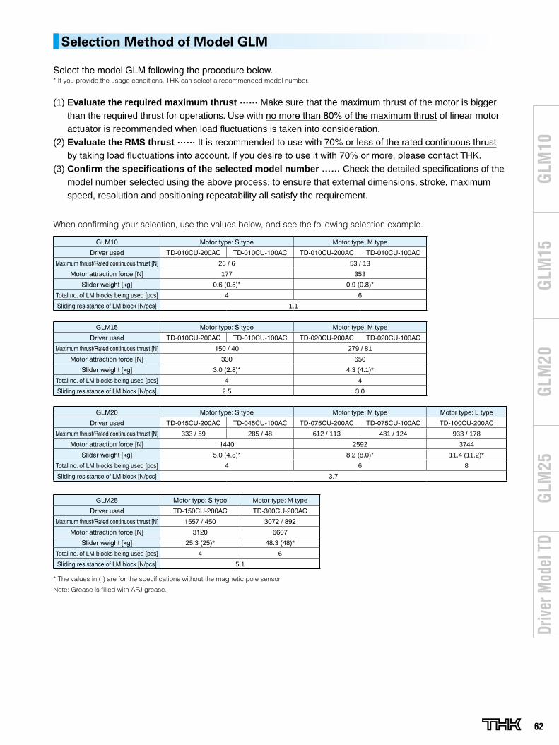
GLM15 Motor type: S type Motor type: M type
Driver used TD-010CU-200AC TD-010CU-100AC TD-020CU-200AC TD-020CU-100AC
Maximum thrust/Rated continuous thrust [N] 150 / 40 279 / 81
Motor attraction force [N] 330 650
Slider weight [kg] 3.0 (2.8)* 4.3 (4.1)*
Total no. of LM blocks being used [pcs] 4 4
Sliding resistance of LM block [N/pcs] 2.5 3.0
GLM20 Motor type: S type Motor type: M type Motor type: L type
Driver used TD-045CU-200AC TD-045CU-100AC TD-075CU-200AC TD-075CU-100AC TD-100CU-200AC
Maximum thrust/Rated continuous thrust [N] 333 / 59 285 / 48 612 / 113 481 / 124 933 / 178
Motor attraction force [N] 1440 2592 3744
Slider weight [kg] 5.0 (4.8)* 8.2 (8.0)* 11.4 (11.2)*
Total no. of LM blocks being used [pcs] 4 6 8
Sliding resistance of LM block [N/pcs] 3.7
GLM25 Motor type: S type Motor type: M type
Driver used TD-150CU-200AC TD-300CU-200AC
Maximum thrust/Rated continuous thrust [N] 1557 / 450 3072 / 892
Motor attraction force [N] 3120 6607
Slider weight [kg] 25.3 (25)* 48.3 (48)*
Total no. of LM blocks being used [pcs] 4 6
Sliding resistance of LM block [N/pcs] 5.1
* The values in ( ) are for the specifications without the magnetic pole sensor.
Note: Grease is filled with AFJ grease.
62
GLM
20G
LM10
GLM
15G
LM25
Driv
er M
odel
TD
Selection Method of Model GLM
Select the model GLM following the procedure below.* If you provide the usage conditions, THK can select a recommended model number.
(1) Evaluate the required maximum thrust …… Make sure that the maximum thrust of the motor is bigger than the required thrust for operations. Use with no more than 80% of the maximum thrust of linear motor actuator is recommended when load fluctuations is taken into consideration.
(2) Evaluate the RMS thrust …… It is recommended to use with 70% or less of the rated continuous thrust by taking load fluctuations into account. If you desire to use it with 70% or more, please contact THK.
(3) Confirm the specifications of the selected model number …… Check the detailed specifications of the model number selected using the above process, to ensure that external dimensions, stroke, maximum speed, resolution and positioning repeatability all satisfy the requirement.
When confirming your selection, use the values below, and see the following selection example.
GLM10 Motor type: S type Motor type: M type
Driver used TD-010CU-200AC TD-010CU-100AC TD-010CU-200AC TD-010CU-100AC
Maximum thrust/Rated continuous thrust [N] 26 / 6 53 / 13
Motor attraction force [N] 177 353
Slider weight [kg] 0.6 (0.5)* 0.9 (0.8)*
Total no. of LM blocks being used [pcs] 4 6
Sliding resistance of LM block [N/pcs] 1.1
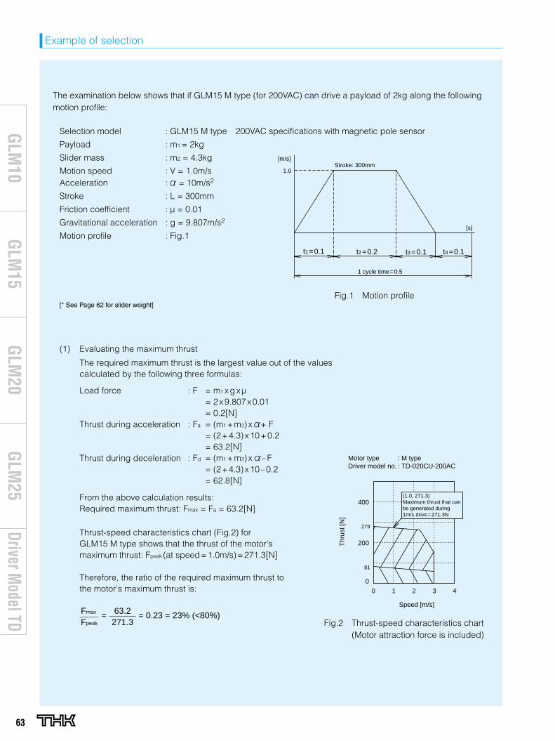
The examination below shows that if GLM15 M type (for 200VAC) can drive a payload of 2kg along the following motion profile:
Selection model : GLM15 M type 200VAC specifications with magnetic pole sensor
Payload : m1 = 2kg
Slider mass : m2 = 4.3kg
Motion speed : V = 1.0m/sAcceleration : = 10m/s2
Stroke : L = 300mm
Friction coefficient : μ = 0.01
Gravitational acceleration : g = 9.807m/s2
Motion profile : Fig.1
[* See Page 62 for slider weight]
Evaluating the maximum thrust
The required maximum thrust is the largest value out of the valuescalculated by the following three formulas:
Load force : F = m1 xgxµ = 2x9.807x0.01 = 0.2[N]Thrust during acceleration : Fa = (m1 +m2)x + F = (2+4.3)x10+0.2 = 63.2[N]Thrust during deceleration : Fd = (m1 +m2)x –F = (2+4.3)x10–0.2 = 62.8[N]
From the above calculation results: Required maximum thrust: Fmax = Fa = 63.2[N]
Thrust-speed characteristics chart (Fig.2) for GLM15 M type shows that the thrust of the motor's maximum thrust: Fpeak (at speed=1.0m/s)=271.3[N]
Therefore, the ratio of the required maximum thrust to the motor's maximum thrust is:
Fmax
Fpeak
63.2271.3
= = 0.23 = 23% (<80%)
(1)
Fig.1 Motion profile
Stroke: 300mm1.0
[m/s]
t1 =0.1 t3 =0.1
1 cycle time=0.5
t2 =0.2 t4 =0.1
[s]
Fig.2 Thrust-speed characteristics chart (Motor attraction force is included)
Speed [m/s]
Motor type : M typeDriver model no. : TD-020CU-200AC
0
0 1 32 4
400
200
279
81
Thr
ust [
N]
(1.0, 271.3)Maximum thrust that can be generated during 1m/s drive=271.3N
63
Driver Model TD
GLM
20G
LM10
GLM
15G
LM25
Example of selection
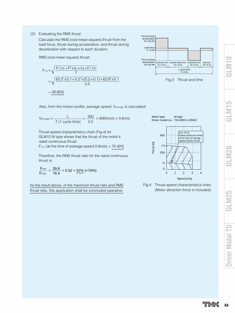
As the result above, of the maximum thrust ratio and RMS thrust ratio, this application shall be concluded operative.
39.8[N]
Fa2 x t1 +F2 x (t2 + t4)+Fd
2 x t3
T
=
=
63.22 x0.1+0.22 x (0.2+0.1)+62.82 x0.10.5
Frms
Fcont.39.876.4
= = 0.52 = 52% (<70%)
Evaluating the RMS thrust
Calculate the RMS (root-mean-square) thrust from the load force, thrust during acceleration, and thrust during deceleration with respect to each duration.
RMS (root-mean-square) thrust:
Thrust-speed characteristics chart (Fig.4) for GLM15 M type shows that the thrust of the motor's rated continuous thrust:Fcont. (at the time of average speed 0.6m/s) = 76.4[N]
Therefore, the RMS thrust ratio for the rated continuous thrust is:
(2)
Frms =
Thrust during acceleration
Fa=63.2N
Load force F=0.2N
Thrust during deceleration
Fd=62.8NAcceleration time
t1=0.1sConstant speed time
t2=0.2sDeceleration time
t3=0.1sStop time t4=0.1s
1 cycle timeT=0.5s
Fig.3 Thrust and time
279
81
Speed [m/s]
Motor type : M typeDriver model no. : TD-020CU-200AC
0
0 1 32 4
400
200Thr
ust [
N]
(0.6, 76.4)Rated continuous thrust at the time of average speed 0.6m/s=76.4N
Fig.4 Thrust-speed characteristics chart (Motor attraction force is included)
Also, from the motion profile, average speed: Vaverage is calculated:
Vaverage = L = 300 = 600mm/s = 0.6m/s T (1 cycle time) 0.5
64
GLM
20G
LM10
GLM
15G
LM25
Driv
er M
odel
TD
All rights reserved
“LM GUIDE,” “Caged Ball,” and “ ” are registered trademarks of THK CO., LTD. The actual products may differ from the pictures and photographs in this catalog. Outward appearances and specifications is subject to change without notification for purposes of improvement, please inquire before using them. Although great care has been taken in the production of this catalog, THK will not take any responsibility for damage resulting from typographical errors or omissions. In exporting our products and technology, or selling them for the purpose of export, THK has a basic policy of observing laws relating to foreign exchange,
trade and other laws. For export of THK products as single items, contact THK in advance.
Linear Motor Actuators GLM10,15,20,25
Precautions on Use Environment
The wrong environment can cause failure for the actuator and driver. The best places to use the device are as follows:• For actuators, an environment with a room and ambient temperature from 0 to 40 °C and humidity of no more than 80% RH that will not expose the
product to freezing or condensation.• For drivers, an environment with a room and ambient temperature from 0 to 50 °C and humidity of no more than 90% RH that will not expose the
product to freezing or condensation.• A place free from corrosive gas or flammable gas.• Places where none of the following are flying around: iron particles, or any other conductive particles, dust, oil mist, cutting fluid, water, salt,
organic solvents.• Places that are not exposed to direct sunlight or radiant heat.• Places where no strong electric fields or strong magnetic fields occur.• Places where vibration or impact are not transmitted to the unit.• Places that are easy to inspect and clean.
Safety Precautions• Do not drop or knock this product. Doing so may cause injury or damage the unit.• Unnecessarily disassembling this product may allow foreign objects to enter and reduce functionality. Also, there is a risk of electric shock from
the driver.• The PL seal is attached to the end plate of the unit body. If the user has selected a unit option without an end plate, no PL seal will be attached.
Therefore, the user must prepare his own PL seal.• The magnet plate (stator) is a very powerful magnet. Keep magnetic bodies (particularly metals) away from the magnet plate. There is a risk of
getting the finger(s) jammed between the metal body and the magnet due to the attractive force of the magnet. Also, persons using cardiac pacemakers should absolutely stay away from the magnet.
• Never touch the moving section of the actuator when it is energized. Also, when the product is in motion, or in a state of readiness for motion, do not enter the movement zone of the actuator.
• When carrying out installation, adjustment, inspection or maintenance of the actuator unit, driver or connected associated devices, always remove all plugs from the power sockets, and use locking or safety plugs etc. so that no one but an operator can turn on the power again. Also, display a notice explaining what work is in progress in a position that is readily seen.
• If two or more people are involved in the operation, confirm the procedures such as sequences, signs, and abnormalities in advance, and appoint another person for monitoring the operation.
• Read the manual carefully, understanding the content properly, and be sure to observe all safety precautions.
HEAD OFFICE 3-11-6, NISHI-GOTANDA, SHINAGAWA-KU, TOKYO 141-8503 JAPAN INTERNATIONAL SALES DEPARTMENT PHONE:+81-3-5434-0351 FAX:+81-3-5434-0353
Global site : http://www.thk.com/
TAIWANTHK TAIWAN CO.,LTD.
TAIPEI HEAD OFFICEPhone:+886-2-2888-3818TAICHUNG OFFICEPhone:+886-4-2359-1505 TAINAN OFFICEPhone:+886-6-289-7668
KOREASEOUL REPRESENTATIVE OFFICE
Phone:+82-2-3468-4351SINGAPORETHK LM SYSTEM Pte. Ltd.
NORTH AMERICATHK America,Inc.
HEADQUARTERSPhone:+1-847-310-1111 Fax:+1-847-310-1271CHICAGO OFFICEPhone:+1-847-310-1111 Fax:+1-847-310-1182NORTH EAST OFFICE Phone:+1-845-369-4035 Fax:+1-845-369-4909ATLANTA OFFICEPhone:+1-770-840-7990 Fax:+1-770-840-7897LOS ANGELES OFFICEPhone:+1-949-955-3145 Fax:+1-949-955-3149SAN FRANCISCO OFFICEPhone:+1-925-455-8948 Fax:+1-925-455-8965DETROIT OFFICEPhone:+1-248-858-9330 Fax:+1-248-858-9455TORONTO OFFICEPhone:+1-905-820-7800 Fax:+1-905-820-7811
SOUTH AMERICATHK Brasil LTDA
Phone:+55-11-3767-0100 Fax:+55-11-3767-0101EUROPETHK GmbH
DÜSSELDORF OFFICEPhone:+49-2102-7425-0 Fax:+49-2102-7425-299
EUROPEAN HEADQUARTERSPhone:+49-2102-7425-0 Fax:+49-2102-7425-217
SHANGHAI OFFICEPhone:+86-21-6219-3000 Fax:+86-21-6219-9890BEIJING OFFICEPhone:+86-10-8441-7277 Fax:+86-10-6590-3557CHENGDU OFFICEPhone:+86-28-8526-8025 Fax:+86-28-8525-6357GUANGZHOU OFFICEPhone:+86-20-8523-8418 Fax:+86-20-3801-0456
CHINATHK (CHINA) CO.,LTD.
TURKEY OFFICEPhone:+90-216-362-4050 Fax:+90-216-569-7150PRAGUE OFFICEPhone:+420-2-41025-100 Fax:+420-2-41025-199
FRANKFURT OFFICEPhone:+49-2102-7425-650 Fax:+49-2102-7425-699STUTTGART OFFICEPhone:+49-7150-9199-0 Fax:+49-7150-9199-888MÜNCHEN OFFICEPhone:+49-8937-0616-0 Fax:+49-8937-0616-26U.K. OFFICEPhone:+44-1908-30-3050 Fax:+44-1908-30-3070ITALY MILANO OFFICEPhone:+39-039-284-2079 Fax:+39-039-284-2527ITALY BOLOGNA OFFICEPhone:+39-051-641-2211 Fax:+39-051-641-2230SWEDEN OFFICEPhone:+46-8-445-7630 Fax:+46-8-445-7639 AUSTRIA OFFICEPhone:+43-7229-51400 Fax:+43-7229-51400-79SPAIN OFFICEPhone:+34-93-652-5740 Fax:+34-93-652-5746
EINDHOVEN OFFICETHK Europe B.V.
THK France S.A.S.Phone:+33-4-3749-1400
Phone:+31-040-290-9500 Fax:+31-040-290-9599
Fax:+33-4-3749-1401
HEADQUARTERSPhone:+86-411-8733-7111 Fax:+86-411-8733-7000
THK (SHANGHAI) CO.,LTD.Phone:+86-21-6275-5280 Fax:+86-21-6219-9890
Fax:+886-2-2888-3819
Fax:+886-4-2359-1506
Fax:+886-6-289-7669
Fax:+82-2-3468-4353
Fax:+65-6884-5550INDIABANGALORE REPRESENTATIVE OFFICE
Phone:+91-80-2330-1524
Phone:+65-6884-5500
Fax:+91-80-2314-8226
©THK CO., LTD. 200903003 E8 Printed in Japan
High-speed, low dust-generation and low noise have been achieved
Dedicated driver has been developed
UL Certified products & CE Marked products
GLM10,15,20,25
Linear MotorActuators
CATALOG No.339-4E-CU
Lin
ea
r M
oto
r A
ctu
ato
rs
GL
M10
, 15
, 20
, 25
UL
Ce
rtified
pro
du
cts
& C
E M
ark
ed
pro
du
cts
High-speed, low dust-generation and low noise have been achieved
Dedicated driver has been developed
UL Certified products & CE Marked products
UL
Ce
rtified
pro
du
cts
& C
E M
ark
ed
pro
du
cts
Related Documents