Ⅱ-101 Ⅱ-102 Linear Ball Spline C-Lube Linear Ball Spline MAG Linear Ball Spline G

Welcome message from author
This document is posted to help you gain knowledge. Please leave a comment to let me know what you think about it! Share it to your friends and learn new things together.
Transcript

Ⅱ-101 Ⅱ-102
Linear Ball Spline
C-Lube Linear Ball Spline MAGLinear Ball Spline G

1N=0.102kgf=0.2248lbs.1mm=0.03937inch
Features of Linear Ball Spline series ①
IKO Linear Ball Spline is a linear motion rolling guide in which an external cylinder makes linear motion along the spline shaft. Since the structure lets a ball to rotate on the spline track groove, it can receive not only the radial load but also rotating torque. Therefore it best fits the structure in which torque transmission and linear motion take place in parallel.
Both high speed durability performance and maintenance free performance are achievedC-lube Linear Ball Spline MAG realizes a long term maintenance free using the built-in lubrication parts C-Lube for ball recirculation way in external cylinder. Since the lubrication oil inside C-Lube maintains the lubrication performance for a long time, it reduces the annoying lubricating management works and also allows total system cost saving by reducing the oil supply structures.
High rigidity despite of compact sizeThe structure places large diameter balls in two rows and has four-point contact with the track, allowing greater rigidity and compact design.
Low frictional resistance and smooth motionThe optimum design based on the thorough analysis of ball recirculating route realized low frictional resistance and smooth linear motion durable for high speed operations.
Allows high accuracy and accurate positioningPreload removes the clearance along the rotation direction, allowing accurate positioning along the rotation direction.
Excellent features of compact linear ball spline realized by a simple structure by four-points contact in two-row raceways
Durability test assuming the chip mounter
《Test conditions》
《Result》
Number of strokes by 100 million times
0 2.0 4.0 6.0 8.0 10.0
Endured 779 million strokes!MAG 5
Endured 743 million strokes!MAG 6
Endured 692 million strokes!MAG 8
Endured 767 million strokes!MAG 10
Endured 880 million strokes!MAG 12
For the load from all directionsit gives a good balance
and high rigidity!
No play along the rotation direction!
Four point contact
Lubrication conditions
Test method
Operation condition
PostureMaximum velocity
AccelerationNumber of cycle
Stroke length
Vibration test machine
860 mm/s 10 G 18.2 Hz 15 mm
MAG
Vibration machine
Smooth
Endured total strokes of 200 million times without a problem, only by lubrication oil inside C-Lube, for vertical shaft and super high tact operation!Realized the maintenance free of 10 years of use equivalent to 10 years, in the test condition assuming the use for general chip mounters!!
Achieved maintenance free of more than 600 million total strokes in this severe operation conditions!!
Only lubrication oil inside C-lube, with no pre-packed grease
Vertical
Four point contact
Four point contact
Ⅱ-104Ⅱ-103

1N=0.102kgf=0.2248lbs.1mm=0.03937inch
Features of Linear Ball Spline series ②Free combination is enabled for model/accuracy/preload!!
Extreme interchangeable system
Interchangeable specification
A wide variety of models with different sectional shape and length are provided, for free replacement on the same spline shaft.
Select the products as many as you wish.
Spline shaft
High carbon steel spline hollow shaft
Spline shaft interchangeability
C-Lube Linear Ball Spline MAG Linear Ball Spline G Any combination of external
cylinders and spline shafts can be selected!
Any combination of external cylinders and spline shafts
can be selected!
External cylinder Spline shaft Assembled set
External cylinder interchangeability
Shape of external cylinders
Standard type Flange type
Standard Long
Length of external cylinder
External cylinder interchangeability
The simple structure of four-contact in two-row race-way yields small manufacturing errors or accuracy mea-surement errors, allowing the maintenance of each raceway in the high dimensions accuracy.Two accuracy classes of ordinary and high level are provided, to support even high traveling accuracy pur-poses.
The simple structure is leveraged to allow dimensions to be managed with high accuracy, for preloaded exter-nal cylinders that are interchangeable.It supports the applications requiring the rigidity of one higher rank.
By exchanging the external cylinder of Linear Ball Spline MAG of interchangeable specification with an external cylinder of C-Lube Linear Ball Spline G, you can achieve the maintenance free without changing the spline shaft.
Interchangeable specification allows for external cylinder and spline shaft dimensions to be strictly managed
based on unique advanced processing technology, resulting in an unparalleled level of interchangeability.
This allows external cylinders and spline shafts to be handled independently and selected in any combination,
allowing you to order just what you need, when you need it, and in the quantity you require.
Accuracy interchangeability
Preload interchangeability
Maintenance free is achieved only by replacing the external cylinder!
Light preload
Standard preload
High carbon steel spline solid shaftStainless steel spline solid shaft
It allows the rigidity improvement of units without design changes!It allows the rigidity improvement of units without design changes!
It allows the accuracy improvement of units without design changes!It allows the accuracy improvement
of units without design changes!It allows the accuracy improvement
of units without design changes!
Requirements of ;
Help● Wish to improve the rigidity and life of machines● Wish to improve the accuracy of machines● Wish to replace the external cylinder immediately● There are not enough external cylinders● Wish to replace the spline shaft immediately● The length of spline shaft is not sufficient● Wish to store only the external cylinders
in stock for emergency
Interchangeable specification realizes ;
Sorted out● Wish to prepare for a sudden design change● Wish to select freely the combination of high
accuracy and preload● Independent handling of external cylinders and
spline shafts● Free and independent combination of external
cylinders and spline shafts● Compactness - independent storing of
external cylinders and spline shafts
Touch
External cylinder Spline shaft
Rigidity is necessary after all!
Ⅱ-105 Ⅱ-106
Load Rating and Life Identification Number and Specification
2● Extremely small size realized by simple structure
The minimum size LSAG2 realizes an unparalleled small size of 2 mm shaft diameter and 6 mm external cylinder's outside diameter.
1Points● Compact size
Uses a unique ball retaining mechanism without using a retainer, allowing a small external cylinder outside diameter against shaft diameter. 3
● Wide range of variations for your needsThe external cylinder shape can be selected from two types, the standard (cylindrical shape) type and the flange type, and there are two types with different length of external cylinder with same section.Also for spline shaft, the solid shaft and the hollow shaft that allows piping/wiring/air removal are prepared for your selection to meet the requirements of mechanical/unit specifications.
4The spline shafts made of stainless steel are highly corrosion-resistant. They are suitable where rust prevention oil is not preferred, such as in a cleanroom environment.
LSAGLinear Ball Spline G
C-Lube Linear Ball Spline MAG
MAG
C-Lube Maintenance Free Series
Long term maintenance free supported!
The aquamarine end plate is the symbol of maintenance free.
● Stainless steel shaft with high corrosion resistance
External cylinder
Keyway
External cylinder body
Ball
C-Lube
End Plate
Seal
Spline shaft
Ⅱ-108Ⅱ-1071N=0.102kgf=0.2248lbs.1mm=0.03937inch
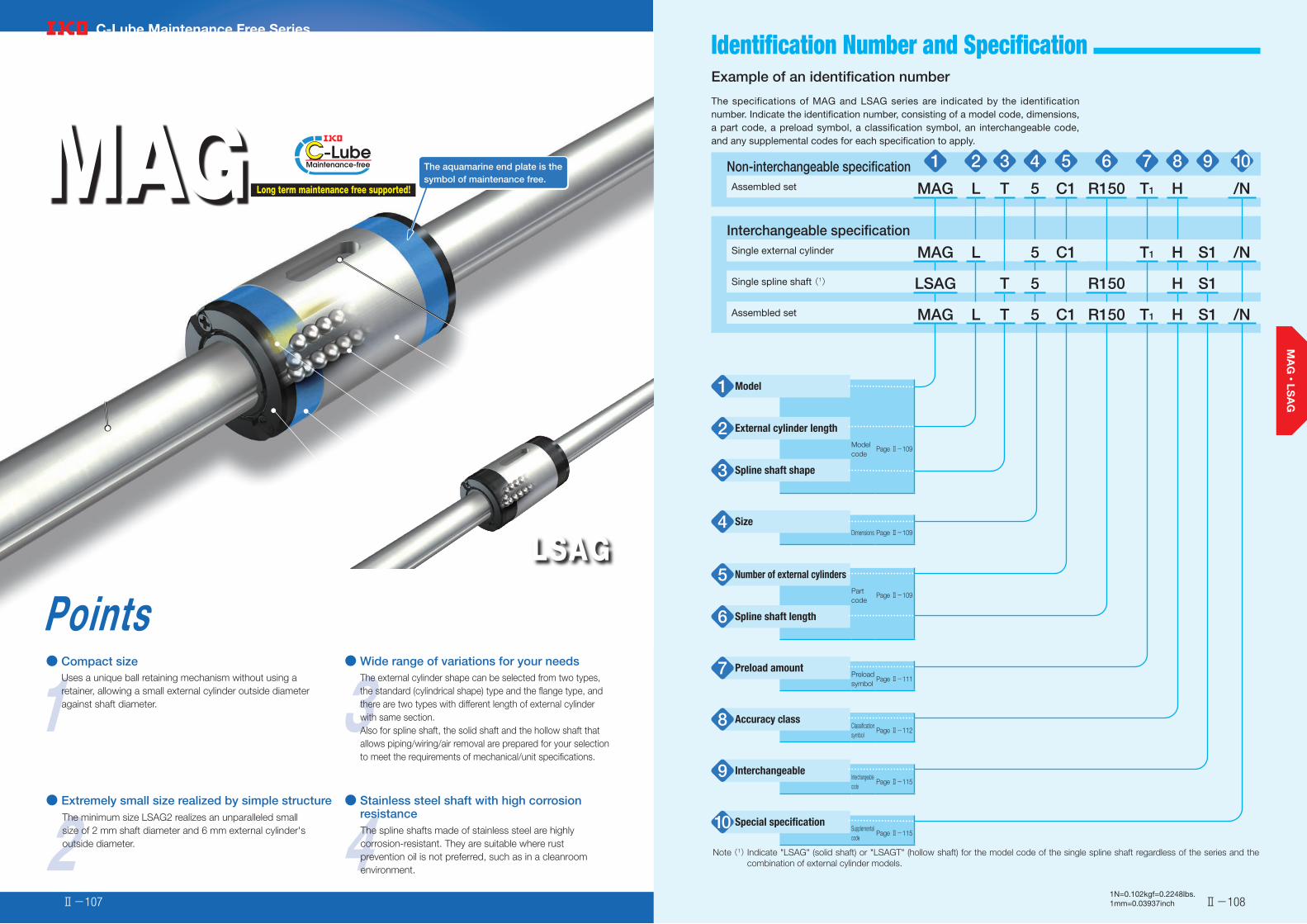
Example of an identification number
The specifications of MAG and LSAG series are indicated by the identification number. Indicate the identification number, consisting of a model code, dimensions, a part code, a preload symbol, a classification symbol, an interchangeable code, and any supplemental codes for each specification to apply.
Non-interchangeable specification 1 2 3 4 5 6 7 8 9 10Assembled set MAG L T 5 C1 R150 T1 H /N
Interchangeable specificationSingle external cylinder MAG L 5 C1 T1 H S1 /N
Single spline shaft (1) LSAG T 5 R150 H S1
Assembled set MAG L T 5 C1 R150 T1 H S1 /N
Model1
External cylinder length2Modelcode
Page Ⅱ-109
Spline shaft shape3
Size4Dimensions Page Ⅱ-109
Number of external cylinders5Partcode
Page Ⅱ-109
Spline shaft length6
Preload amount7 Preloadsymbol
Page Ⅱ-111
Accuracy class8 Classificationsymbol
Page Ⅱ-112
Interchangeable9 Interchangeablecode
Page Ⅱ-115
Special specification10 Supplementalcode
Page Ⅱ-115
Note (1) Indicate "LSAG" (solid shaft) or "LSAGT" (hollow shaft) for the model code of the single spline shaft regardless of the series and the combination of external cylinder models.

Spline Shaft Shape・Size・Number of External Cylinders・Spline Shaft Length-Identification Number and Specification -Model・External Cylinder Length・
Ⅱ-110Ⅱ-1091N=0.102kgf=0.2248lbs.1mm=0.03937inch
C-Lube Linear Ball Spline MAG(MAG series)
Standard typeFlange type
:MAG:MAGF
Linear Ball Spline G(1)(LSAG series)
Standard typeFlange type
:LSAG:LSAGF
For applicable models and sizes, see Table 1.Indicate "LSAG" (solid shaft) or "LSAGT" (hollow shaft) for the model code of the single spline shaft regardless of the series and the combination of external cylinder models.
Note (1) This model has no built-in C-Lube.
StandardLong
:No symbol:L
For applicable models and sizes, see Table 1.
Solid shaftHollow shaft
:No symbol:T
For applicable models and sizes, see Table 1.
2, 3, 4, 5, 6, 8, 10, 12, 1520, 25, 30
For applicable models and sizes, see Table 1.
:C○ For an assembled set, indicates the number of external cylinders assembled on a spline shaft. For a single external cylinder, only "C1" is specified.
:R○ The spline shaft length is indicated in mm.For standard and maximum lengths, see the dimension table.
Model1
External cylinder length2
Spline shaft shape3
Size4
Number of external cylinders5
Spline shaft length6
Table 1 Models and sizes of MAG and LSAG series
ShapeExternal cylinder
lengthModel
Size
2 3 4 5 6 8 10 12 15 20 25 30
Standard typeSolid shaft
MAG - - ○ ○ ○ ○ ○ ○ - - - -
LSAG ○ ○ ○ ○ ○ ○ ○ ○ ○ ○ ○ ○
MAGL - - ○ ○ ○ ○ - - - - - -
LSAGL - - - ○ ○ ○ ○ ○ ○ ○ ○ ○
Standard typeHollow shaft
MAGT - - ○ ○ ○ ○ ○ ○ - - - -
LSAGT - - ○ ○ ○ ○ ○ ○ - - - -
MAGLT - - ○ ○ ○ ○ - - - - - -
LSAGLT - - - ○ ○ ○ ○ ○ - - - -
Flange typeSolid shaft
MAGF - - - ○ ○ ○ ○ ○ - - - -
LSAGF ○ ○ ○ ○ ○ ○ ○ ○ ○ ○ ○ ○
LSAGFL - - - ○ ○ ○ ○ ○ ○ ○ ○ ○
Flange typeHollow shaft
MAGFT - - - ○ ○ ○ ○ ○ - - - -
LSAGFT - - ○ ○ ○ ○ ○ ○ - - - -
LSAGFLT - - - ○ ○ ○ ○ ○ - - - -
Remark: For the models indicated in , the interchangeable specification is available.
Standard
Long
Standard
Long
Standard
Long
Standard
Long

-Preload Amount- -Accuracy Class-
Ⅱ-111 Ⅱ-1121N=0.102kgf=0.2248lbs.1mm=0.03937inch
OrdinaryHighPrecision
:No symbol:H:P
For interchangeable specification products, assemble an external cylinder and a spline shaft of the same accuracy class.For applicable accuracy class, see Table 4.For details of accuracy class, see Table 5, Table 6, and Table 7.
Accuracy class8Clearance Standard Light preload
:T0
:No symbol:T1
Specify this item for an assembled set or a single external cylinder.For details of the preload amount, see Table 2.For applicable preload types, see Table 3.
Preload amount7
Table 4 Application of accuracy class
Size
Class(classification symbol)
Ordinary(No symbol)
High(H)
Precision(P)
2 ○ ○ ○3 ○ ○ ○4 ○ ○ ○5 ○ ○ ○6 ○ ○ ○8 ○ ○ ○
10 ○ ○ ○12 ○ ○ ○15 ○ ○ ○20 ○ ○ ○25 ○ ○ ○30 ○ ○ ○
Remark: The mark indicates that interchangeable specifications products are available.
Table 2 Preload amount
ItemPreload type
Preload symbol
Preload amount
NOperational conditions
Clearance T0 0(1) ・ Very light motionStandard (No symbol) 0(2) ・ Light and precise motion
Light preload T1 0.02 C0
・ Almost no vibrations・ Load is evenly balanced・ Light and precise motion
Notes (1) There is zero or subtle clearance. (2) Indicates zero or minimal amount of preload.
Remark: C0 indicates the basic static load rating.
Table 5 Tolerance of each part
unit: μm
Size
Relative to axial line of supporting part of spline shaft ③ Perpendicularity of mounting surface of flange with respect to axial line of spline shaft(2)
① Radial runout of periphery of parts mounting part(1)
② Perpendicularity of spline part end face(1)
Ordinary High Precision Ordinary High Precision Ordinary High Precision(No symbol) (H) (P) (No symbol) (H) (P) (No symbol) (H) (P)
2 33 14 8 22 9 6 27 11 83 33 14 8 22 9 6 27 11 84 33 14 8 22 9 6 27 11 85 33 14 8 22 9 6 27 11 86 33 14 8 22 9 6 27 11 88 33 14 8 22 9 6 27 11 8
10 41 17 10 22 9 6 33 13 912 41 17 10 22 9 6 33 13 915 46 19 12 27 11 8 33 13 920 46 19 12 27 11 8 33 13 925 53 22 13 33 13 9 39 16 1130 53 22 13 33 13 9 39 16 11
Notes (1) The values are for the processed shaft ends. (2) Applicable to the flange type.
A-B
A D B
C
A-B
A-B
Table 7
A-B
A-B
2 3 2
11
Parts mounting part
Support part
Spline partExternal cylinder
Parts mounting part
Support part
D C
D C
Table 3 Application of preload
Size
Preload type(preload symbol)
Clearance(T0)
Standard(No symbol)
Light preload(T1)
2 ○ ○ -3 ○ ○ -4 ○ ○ -5 - ○ ○6 - ○ ○8 - ○ ○
10 - ○ ○12 - ○ ○15 - ○ ○20 - ○ ○25 - ○ ○30 - ○ ○
Remark: The mark indicates that interchangeable specifications products are available.
-Accuracy Class- -Accuracy Class-
Ⅱ-113 Ⅱ-1141N=0.102kgf=0.2248lbs.1mm=0.03937inch
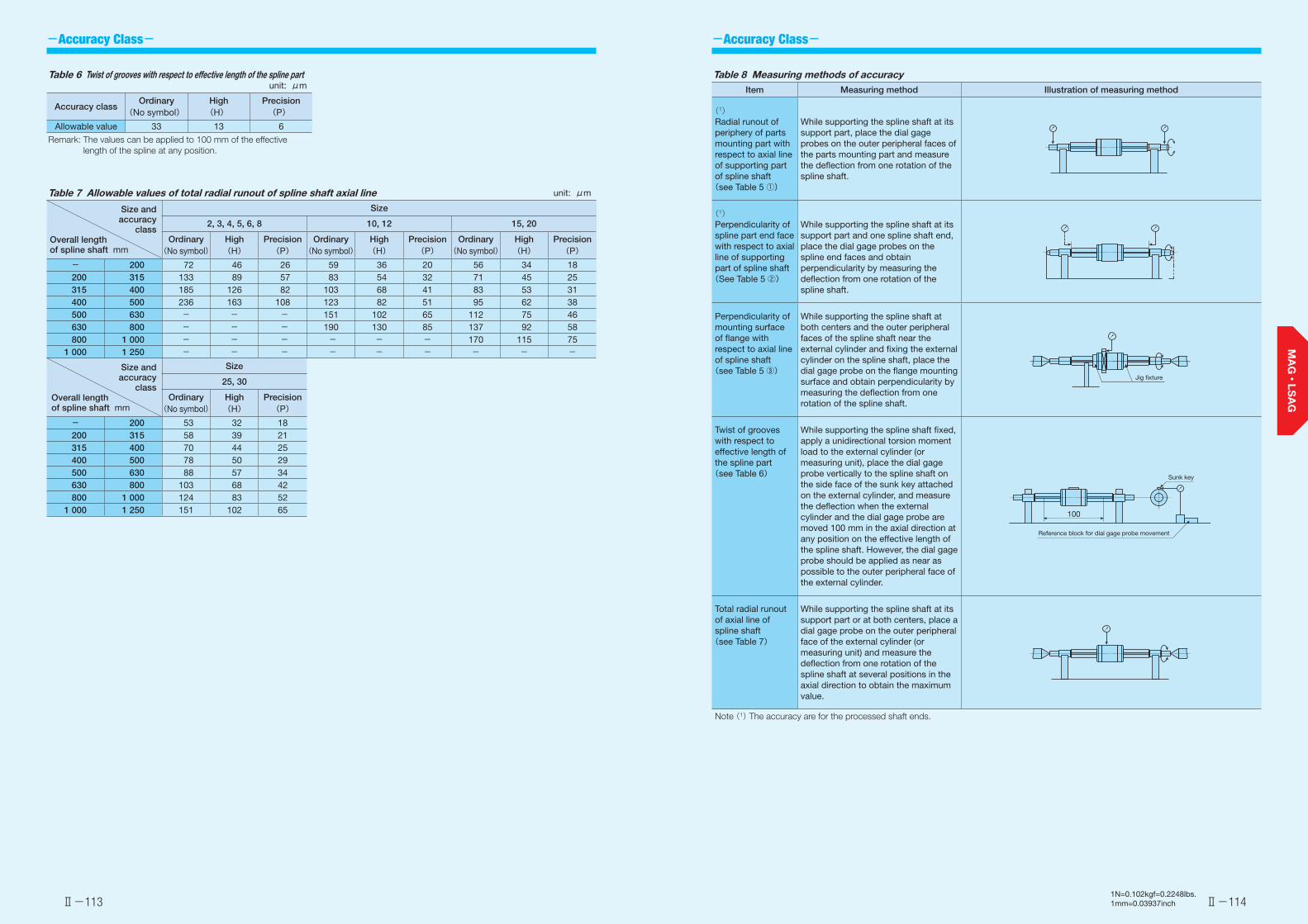
Table 6 Twist of grooves with respect to effective length of the spline part unit: μm
Accuracy classOrdinary
(No symbol)High(H)
Precision(P)
Allowable value 33 13 6
Remark: The values can be applied to 100 mm of the effective length of the spline at any position.
Table 8 Measuring methods of accuracyItem Measuring method Illustration of measuring method
(1)Radial runout of periphery of parts mounting part with respect to axial line of supporting part of spline shaft(see Table 5 ①)
While supporting the spline shaft at its support part, place the dial gage probes on the outer peripheral faces of the parts mounting part and measure the deflection from one rotation of the spline shaft.
(1)Perpendicularity of spline part end face with respect to axial line of supporting part of spline shaft(See Table 5 ②)
While supporting the spline shaft at its support part and one spline shaft end, place the dial gage probes on the spline end faces and obtain perpendicularity by measuring the deflection from one rotation of the spline shaft.
Perpendicularity of mounting surface of flange with respect to axial line of spline shaft(see Table 5 ③)
While supporting the spline shaft at both centers and the outer peripheral faces of the spline shaft near the external cylinder and fixing the external cylinder on the spline shaft, place the dial gage probe on the flange mounting surface and obtain perpendicularity by measuring the deflection from one rotation of the spline shaft.
Twist of grooves with respect to effective length of the spline part(see Table 6)
While supporting the spline shaft fixed, apply a unidirectional torsion moment load to the external cylinder (or measuring unit), place the dial gage probe vertically to the spline shaft on the side face of the sunk key attached on the external cylinder, and measure the deflection when the external cylinder and the dial gage probe are moved 100 mm in the axial direction at any position on the effective length of the spline shaft. However, the dial gage probe should be applied as near as possible to the outer peripheral face of the external cylinder.
Total radial runout of axial line of spline shaft(see Table 7)
While supporting the spline shaft at its support part or at both centers, place a dial gage probe on the outer peripheral face of the external cylinder (or measuring unit) and measure the deflection from one rotation of the spline shaft at several positions in the axial direction to obtain the maximum value.
Note (1) The accuracy are for the processed shaft ends.
Jig fixture
Reference block for dial gage probe movement
Sunk key
100
Table 7 Allowable values of total radial runout of spline shaft axial line unit: μm
Size and accuracy
classOverall length of spline shaft mm
Size
2, 3, 4, 5, 6, 8 10, 12 15, 20
Ordinary(No symbol)
High(H)
Precision(P)
Ordinary(No symbol)
High(H)
Precision(P)
Ordinary(No symbol)
High(H)
Precision(P)
- 200 72 46 26 59 36 20 56 34 18200 315 133 89 57 83 54 32 71 45 25315 400 185 126 82 103 68 41 83 53 31400 500 236 163 108 123 82 51 95 62 38500 630 - - - 151 102 65 112 75 46630 800 - - - 190 130 85 137 92 58800 1 000 - - - - - - 170 115 75
1 000 1 250 - - - - - - - - -
Size and accuracy
classOverall length of spline shaft mm
Size
25, 30
Ordinary(No symbol)
High(H)
Precision(P)
- 200 53 32 18200 315 58 39 21315 400 70 44 25400 500 78 50 29500 630 88 57 34630 800 103 68 42800 1 000 124 83 52
1 000 1 250 151 102 65

-Special Specification--Interchangeable Specification・Special Specification-
Ⅱ-115 Ⅱ-1161N=0.102kgf=0.2248lbs.1mm=0.03937inch
Table 11.1 Location and diameter of oil hole on a standard type external cylinder (Supplemental code /OH)
unit: mm
Identification number
F HIdentification
numberF H
LSAG 3 5 1.2 - - -LSAG 4 6
1.5
- - -LSAG 5 9 LSAGL 5 13
1.5LSAG 6 10.5 LSAGL 6 15LSAG 8 12.5 LSAGL 8 18.5LSAG10 15
2LSAGL10 23.5
2LSAG12 17.5 LSAGL12 27LSAG15 20 LSAGL15 32.5LSAG20 25
3LSAGL20 35.5
3LSAG25 30 LSAGL25 42LSAG30 35 LSAGL30 49
Remark: A typical identification number is indicated, but is applied to all LSAG series standard type models of the same size.
LSAG3, LSAG4
(F) Oil hole (H)
Oil hole (H)(F)
Oil hole
Oil hole
Table 11.2 Location and diameter of oil hole on a flange type external cylinder (Supplemental code /OH)
unit: mm
Identification number
F HIdentification
numberF H
LSAGF 3 2.1 1.2 - - -LSAGF 4
2.81.5
- - -LSAGF 5 LSAGFL 5 5.8
1.5LSAGF 63.5
LSAGFL 6 8LSAGF 8 LSAGFL 8 9.5LSAGF10 5
2LSAGFL10 13.3
2LSAGF12 7.5 LSAGFL12 17LSAGF15 9 LSAGFL15 21.5LSAGF20 11
3LSAGFL20 21.5
3LSAGF25 13 LSAGFL25 25LSAGF30 14 LSAGFL30 28
Remark: A typical identification number is indicated, but is applied to all LSAG series flange type models of the same size.
LSAGF3, LSAGF4
F Oil hole (H)
F Oil hole (H) Oil hole
LSAGF(L)30
Oil hole
Oil hole
S1 specificationS2 specificationNon-interchangeable specification
:S1:S2:No symbol
This is specified for the interchangeable specifications. Assemble a spline shaft and an external cylinder with the same interchangeable code. When using in combination with different interchangeable codes, please contact IKO. Note that the combination of interchangeable codes will not have any effect on accuracy.For applicable models and sizes, see Table 1."No symbol" is indicated for non-interchangeable specification.
/BS, /N, /OH, /Q, /RE, /S,/Y
For applicable special specifications, see Table 9.1 and Table 9.2.For combination of multiple special specifications, see Table 10.For details of special specifications, see pages Ⅱ-116 and Ⅱ-117.
Interchangeable9
Special specification10
Stainless steel end plate /BS
The standard synthetic resin end plates are replaced with stainless steel end plates. The total length of the external cylinder remains unchanged.
No seal /N
Seals at both ends of the external cylinder can be replaced with end pressure plates, which do not come in contact with the spline shaft, to reduce frictional resistance.This specification is not effective for dust protection.
Oil hole /OH
An oil hole is created on the external cylinder. For dimensions, see Table 11.1 and Table 11.2.
Stainless steel end plate
End pressure plate End pressure plate
Oil hole (H)(F) Oil hole (H)F
Table 9.1 Application of special specifications (Interchangeable specification, single external cylinder, and assembled set)
Special specificationSupplemental
code
Size
2 3 4 5 6 8 10 12 15 20 25 30
No seal /N - - - ○ ○ ○ ○ ○ ○ ○ ○ ○Oil hole(1) /OH - - - ○ ○ ○ ○ ○ ○ ○ ○ ○With C-Lube plate(1) /Q - - - ○ ○ ○ ○ ○ - - - -
Note (1) Applicable to LSAG series.
Table 9.2 Application of special specifications (Non-interchangeable specification)
Special specificationSupplemental
code
Size
2 3 4 5 6 8 10 12 15 20 25 30
Stainless steel end plate(1) /BS - - - ○ ○ ○ ○ ○ ○ - - -No seal /N - - - ○ ○ ○ ○ ○ ○ ○ ○ ○Oil hole(1) /OH - ○ ○ ○ ○ ○ ○ ○ ○ ○ ○ ○With C-Lube plate(1) /Q - - - ○ ○ ○ ○ ○ - - - -Special environment seal(1) /RE - - - ○ ○ ○ ○ ○ ○ - - -Stainless steel spline shaft(2) /S - - - ○ ○ ○ ○ ○ ○ ○ ○ ○Specified grease(1) /Y - - - ○ ○ ○ ○ ○ ○ - - -
Notes (1) Applicable to LSAG series. (2) Applicable to solid shaft.
Table 10 Combination of supplemental codesN ●
OH ● ○Q ● ○ ○
RE ● - ● ●S ● ● ● ● ●Y ● ● ● - ● ●
BS N OH Q RE S
Remarks 1. The combination of "-" shown in the table is not available. 2. Contact IKO for the combination of the interchangeable specification marked with ●. 3. When using multiple types for combination, please indicate by arranging the symbols in alphabetical order.

-Special Specification-
Ⅱ-118Ⅱ-1171N=0.102kgf=0.2248lbs.1mm=0.03937inch
With C-Lube plate /Q
The C-Lube impregnated with lubrication oil is attached inside the seal of the external cylinder, so that the interval for reapplicating lubricant can be extended. For the total length of the external cylinder with C-Lube plate, see Table 12.
C-Lube C-Lube
Table 12 Dimension of external cylinder with C-Lube plate (Supplemental code /Q)
unit: mm
Identification number
L1
Identification number
L1
LSAG 5 24 LSAGL 5 32LSAG 6 27 LSAGL 6 36LSAG 8 33 LSAGL 8 45LSAG10 38 LSAGL10 55LSAG12 43 LSAGL12 62
Remarks 1. The dimensions of the external cylinder with C-Lube at both ends are indicated.
2. A typical identification number is indicated, but is applied to all LSAG series models of the same size.
C-Lube C-Lube(L1)
Special environment seal /RE
The standard seals are replaced with seals for special environment that can be used at high temperatures. The total length of the external cylinder remains unchanged.
Stainless steel spline shaft /S
The material of the solid spline shaft is changed to stainless steel. The load rating will change to a value obtained by multiplying the load rating for the steel spline shaft by a factor of 0.8.
Specified grease /YCG /YCL /YAF /YBR /YNG
The type of pre-packed grease can be changed by the supplemental code.
① /YCG Low Dust-Generation Grease for Clean Environment CG2 is pre-packed.② /YCL Low Dust-Generation Grease for Clean Environment CGL is pre-packed.③ /YAF Anti-Fretting Corrosion Grease AF2 is pre-packed.④ /YBR MOLYCOTE BR2 Plus Grease [Dow Corning] is pre-packed.⑤ /YNG No grease is pre-packed.
Special environment seal
Special environment seal
L
θ
L
θ
L
θL
θ
IKO Linear Ball Spline spline shafts can receive loads in all directions. Therefore, attention must be paid to spline shaft strength.
For bending load
For bending load on the spline shaft, select a shaft diameter that fulfills the conditions in formula (1).
M=σ × Z (1)
M :Maximum bending moment acting on spline shaft N·mmσ :Spline shaft allowable bending stress 98 N/mm2
Z :Section modulus of spline shaft mm3 (See Table 13)
For torsion load
For torsion load on the spline shaft, select a shaft diameter that fulfills the conditions in formula (2).
T=τa × Zp (2)
For simultaneous torsion and bending load
For simultaneous torsion and bending load on the spline shaft, calculate the shaft diameters from the equivalent bending moment formula (3) and the equivalent torsion moment formula (4) and use the larger value.
Equivalent bending moment Me
Me = 1(M + M2+T 2)
(3)2
Me =σ × Z
Equivalent torsion moment Te
Te = M 2+T 2
(4) Te =τa × Zp
Stiffness of spline shaft
The torsion angle of the spline shaft caused by torsion moment must not exceed 0.25°per 1 meter.
θ =T × L
×360
(5)G × Ip 2π
0.25°≧1000 θ
L
T :Maximum torsion moment N·mmτa :Spline shaft allowable torsion stress 49 N/mm2
Zp :Polar section modulus of spline shaft mm3 (See Table 13)
θ :Torsion angle °L :Spline shaft length mmG :Shear Modulus 7.9×10⁴ N/mm2
Ip :Polar moment of inertia of section area of spline shaft mm4 (See Table 13)
√
√
Spline shaft strength
M :Maximum bending moment
T :Maximum torsion moment

Ⅱ-120Ⅱ-1191N=0.102kgf=0.2248lbs.1mm=0.03937inch
Dimensions of Attached Key
Table 15 Dimensions and tolerance of attached key
unit: mm
Size R r Cb
Dim. b tolerance
hDim. h
tolerance
5 2
+0.016+0.006
2
0-0.025
3.81
0.16~0.25
65.8
8 2.5 2.5 1.2510
3 37.8
1.512 11.815 3.5
+0.024+0.012
3.50-0.030
16 1.7520 4 4 21.5 225 5 5 23.5 2.5
0.25~0.430 7
+0.030+0.015
70-0.036
27.5 3.5
Remark: No key is attached to the Size 2, 3, and 4 series. For details of how to fix the key, see page Ⅱ-121.
r
r
h
b
C
The MAG and LSAG series standard types have keys shown in Table 15 attached.
Interchangeable specificationSingle external cylinder Example of identification number indication
MAGF 10 C1 T1 H S○ /N
Non-interchangeable specification
Only C1 can be specified.Please specify S1 or S2.
Order quantity
2 pieces
Assembled setExample of identification number indication
MAGF 10 C2 R200 T1 H /N
Single spline shaft Example of identification number indication
LSAG 10 R200 H S○ 1 unit
Assembled setExample of identification number indication
MAGF 10 C2 R200 T1 H S○ /N 1 set
Order quantity
Order quantity
1 setOrder quantity
(When 2 pieces are needed)
(When 1 unit is needed)
(When 1 set is needed)
(When 1 set is needed)
Please specify S1 or S2.
Please specify S1 or S2.
Identification number and quantity for ordering To order an assembled set of MAG and LSAG series, please specify the number of sets based on the number of spline shafts. For single external cylinder or single spline shaft of the interchangeable specification, please specify the number of units.
Load Direction and Load Rating The MAG and LSAG series must be used with their load rating corrected in accordance to the load direction. The basic dynamic load rating and basic static load rating shown in the dimension table should be corrected to values in Table 14.
Table 14 Load ratings corrected for load direction
Load rating and load direction
Size
Basic dynamic load rating Basic static load rating
Load direction Load direction
Downward Upward Lateral Downward Upward Lateral
2~12 C C 1.47C C0 C0 1.73C0
15~30 C C 1.13C C0 C0 1.19C0
Upward load
Downward load
Lateral load
Spline shaft sectional characteristics Table 13 Spline shaft sectional characteristics
Size
Moment of inertia ofsectional area
mm4
Section modulus : Zmm3
Polar moment of inertia of section area of spline shaft: IP
mm4
Polar section modulus : ZP
mm3
Solid shaft Hollow shaft Solid shaft Hollow shaft Solid shaft Hollow shaft Solid shaft Hollow shaft 2 0.60 - 0.65 - 1.4 - 1.4 - 3 3.6 - 2.5 - 7.5 - 5.0 - 4 12 12 6.0 6.0 24 24 12 12 5 29 28 12 11 59 58 24 23 6 61 60 21 20 120 120 41 41 8 190 190 49 47 390 380 98 96 10 470 460 95 93 960 940 190 19012 990 920 170 160 2 010 1 880 330 31015 1 580 - 240 - 3 260 - 480 -20 5 100 - 570 - 10 500 - 1 150 -25 12 000 - 1 080 - 24 800 - 2 200 -30 25 300 - 1 890 - 52 200 - 3 840 -

Lubrication Precaution for Use
Dust Protection
Ⅱ-121 Ⅱ-1221N=0.102kgf=0.2248lbs.1mm=0.03937inch
Lithium-soap base grease with extreme-pressure additive (Alvania EP Grease 2 [SHOWA SHELL SEKIYU K. K.]) is pre-packed in MAG and LSAG series. Additionally, MAG series has C-Lube placed in the recirculation part of balls, so that the interval for reapplicating lubricant can be extended and maintenance works such as grease job can be reduced significantly.Perform re-greasing as below. (1) Size 2, 3, and 4 series Specify either direct application of grease to the spline shaft raceway surface or oil hole specification (/OH). Note that the oil hole specification (/OH) is not available for the Size 2 series. (2) Size 5 and higher series Apply grease directly to the spline shaft raceway surface or the rolling elements. You may also specify the oil hole specification (/OH).
The external cylinders of MAG and LSAG series are equipped with special rubber seals as standard for dust protection. However, if large amount of contaminant or dust are floating, or if large particles of foreign substances such as chips or sand may adhere to the spline shaft, it is recommended to attach a protective cover to the linear motion mechanism.The Size 2, 3, and 4 series are not provided with seals. If the Size 3 and 4 series with seals is needed, contact IKO.
❶Fitting of external cylinderGenerally, transition fit (J7) is used for fitting between the external cylinder and the housing bore. When high accuracy and high rigidity are not required, clearance fit (H7) can also be used.
❷ Typical mounting structureMounting examples of the external cylinder are shown in Fig. 1.The rotation detent for external cylinders of the Size 2, 3, and 4 series should be mounted using the countersink provided on the external cylinder. Use screws M1.2 to M1.6 for Size 2, M1.6 to M2 for Size 3, and M2 to M2.5 for Size 4. At this point, be careful not to deform the external cylinder with screws.
Fig. 1 Mounting examples of external cylinder
❸ Multiple external cylinders used in close proximityWhen using multiple external cylinders in close proximity, greater load may be applied than the calculated value depending on the accuracy of the mounting surfaces and reference mounting surfaces of the machine or device. In such cases, allowance for greater applied load than the calculated value should be made.If two or more external cylinders are assembled on a spline shaft and two or more keys are used to fix the rotational direction of the external cylinder, the keyway position of the external cylinders are aligned before delivery. Please contact IKO.
Rotation detent for external cylinder for size 2, 3 and 4
Mounting example for standard type(Oil hole /OH specification)
Mounting example for flange type(Oil hole /OH specification)
❹ Additional machining of spline shaft end・ When machining the outside surface of the spline shaft,
make sure that the maximum diameter of the end machining part does not exceed d1 in the dimension table. If the machined outside surface exceeds d1, it will leave a track groove. ・ Perform annealing if additional machining wil l be
performed. ・ Shaft guide shapes for spline shafts can be prepared upon
request. Please contact IKO for further information.
❺ Operating temperatureMAG Series contains C-Lube. The operating temperature should not exceed 80˚C. The maximum operat ing temperature for LSAG series is 120˚C and temperature up to 100˚C is allowed for continuous operation. When the temperature exceeds 100˚C, contact IKO.When specifying LSAG series special specification with C-Lube plate (supplemental code /Q), utilize it below 80˚C.
❻ Arrangement of flange type (non-interchangeable specification) external cylinder
Table 16 shows arrangements of multiple flange type external cylinders in non-interchangeable specification. Arrangements that are not in Table 16 can be prepared upon request. Contact IKO for further information.
Table 16 Arrangement of flange type (Non-interchangeable specification) external cylinder
Number of external cylinders
Arrangement of external cylinders
1
2
3
4
5
6
❼ When mounting multiple assembled sets at the same time
For interchangeable specification products, assemble an external cyl inder and a spline shaft with the same interchangeable code ("S1" or "S2").For non-interchangeable specification products, use the same combination of external cylinder and spline shaft upon delivery.
❽ Assembly of external cylinder on spline shaftWhen assembling the external cylinder on the spline shaft, correctly fit the grooves of the external cylinder and the spline shaft and move the external cylinder softly in parallel direction. Rough handling may result in damaging of seals or dropping of steel balls.The non-interchangeable specification products are already adjusted so as to provide the best accuracy when the
marks of the external cylinder and the spline shaft face the same direction (see Fig. 2). Be careful not to change the assembly direction.
Fig. 2 Assembly direction of external cylinder
❾ Mounting of external cylinderWhen press-fitting the external cylinder to the housing, assemble them correctly by using a press and a suitable jig fixture. (See Fig. 3.)
Fig. 3 Press-fitting of external cylinder
JAPAN LSAG 10 H MAG10T1 H

Ⅱ-123 Ⅱ-124
C-Lube Linear Ball Spline MAG
TYTx
C, C0
T, T0
Identification number
Inte
rcha
ngea
ble Mass (Ref.)
gExternal cylinder dimensions and tolerances
mmSpline shaft dimensions and tolerances
mmBasic dynamic load rating(4)
Basic static load rating(4)
Dynamic torquerating(4)
Static torquerating(4) Static moment rating(4)
MAG series LSAG series(No C-Lube)
External cylinder
Spline shaft(per 100 mm) L1 L2
R d1(2) d2
C
N
C0
N
T
N・m
T0
N・m
TX
N・m
TY
N・mD Dim. D
toleranceW Dim. W
tolerancet d Dim. d
toleranceL(3) Maximum
length
- LSAG 2(1) - 1.0 2.3 6 0-0.008 8.5 4.7 - - 0.7 - 2 0
-0.010 1.2 - 50 100 100 222 237 0.28 0.30 0.221.4
0.392.4
- LSAG 3(1) - 2.1 5.4 7 0-0.009 10 5.9 - - 0.8 - 3 0
-0.010 2.2 - 100 150 150 251 285 0.45 0.51 0.311.9
0.533.3
MAG 4(1) -
2.5
9.6
8 0-0.009
15
7.9
- - 1 - 4 0-0.012 3.2
-
100 150
200
303 380 0.70 0.87
0.523.80
0.906.50
LSAG 4(1) - 12 0.522.9
0.905.0
MAGT 4(1) -8.2
151.5 150
0.523.80
0.906.50
LSAGT 4(1) - 12 0.522.9
0.905.0
MAGL 4(1) - -4.1
9.621 13.9
- 200 441 665 1.00 1.50 1.50
8.602.60
15.0MAGLT 4(1) - - 8.2 1.5 150
MAG 5 LSAG 5 ○4.8
14.9
10 0-0.009
18 9.4
2 +0.0140 1.2 6 5 0
-0.012 4.2
-
100 150 200
587 641 1.8 1.9 1.07.9
1.813.6MAGT 5 LSAGT 5 ○ 12.4 2
MAGL 5 LSAGL 5 ○8.1
14.926 16.9
- 879 1 180 2.6 3.5 3.2
19.35.5
33.4MAGLT 5 LSAGLT 5 ○ 12.4 2
MAG 6 LSAG 6 ○8.9
19
12 0-0.011
21 12.4
2 +0.0140 1.2 8 6 0
-0.012 5.2
-
150 200 300
711 855 2.5 3.0 1.711.7
3.020.3MAGT 6 LSAGT 6 ○ 16.5 2
MAGL 6 LSAGL 6 ○14.5
1930 21.4
-1 030 1 500 3.6 5.2 5.0
27.68.6
47.8MAGLT 6 LSAGLT 6 ○ 16.5 2
MAG 8 LSAG 8 ○15.9
39
15 0-0.011
25 14.6
2.5 +0.0140 1.5 8.5 8 0
-0.015 7
-
150 200 250
5001 190 1 330 5.5 6.2 3.3
22.05.6
38.1MAGT 8 LSAGT 8 ○ 33 3 400
MAGL 8 LSAGL 8 ○26.5
3937 26.6
- 5001 800 2 470 8.4 11.5 10.3
56.317.897.5MAGLT 8 LSAGLT 8 ○ 33 3 400
Notes (1) No seal is included.(2) d1 represents the maximum diameter for end machining. (Perform annealing if end machining will be performed.)(3) Represents standard length. We can produce other than the standard length, please specify the length of spline shaft by indicating
the length in mm with the identification number.(4) The direction of basic dynamic load rating (C ), basic static load rating (C0), dynamic torque rating (T ), static torque rating and static
moment rating (T0, TX, TY) are shown in the sketches below. The upper values of TX and TY are for one external cylinder and the lower values are for two external cylinders inclose contact.
(L1)
L2
L
d D
MAG(L)(T)4LSAG 2LSAG 3LSAG(T) 4
MAG(L)THollow shaft dimension for LSAG(L)T
d1
t
120°
d1
W
t+0.
05
0
d2
1N=0.102kgf=0.2248lbs.1mm=0.03937inch
MAG・LSAG
52 3302520151210864
Shape
Size
Standard type
MAG R150C25 /NH
MAGModel
Standard typeLSAGNumber of external cylinders(2)
2, 3, 4, 5, 6, 8
Length of spline shaft(150 mm)
S1S2
No symbolNo symbol
Light preloadStandard
Special specificationBS, N, OH, Q, RE, S, YNo symbol
Accuracy class
H HighOrdinary
P Precision
T
Length of external cylinderStandardLongL
No symbol
L
Spline shaft shapeSolid shaftHollow shaftT
No symbol
Clearance
Example of identification number of assembled set
Model code Dimensions Part code Preload symbol
T1
Classification symbol Supplemental codeInterchangeable code
1
2
3
Interchangeable
S2 specificationS1 specificationNon-interchangeable specification
9Preload amount
T1
T0
7
108
1 72 1098543 6
4
5
6
Size

Ⅱ-125 Ⅱ-126
C-Lube Linear Ball Spline MAG
TYTx
C, C0
T, T0
Identification number
Inte
rcha
ngea
ble Mass (Ref.)
gExternal cylinder dimensions and tolerances
mmSpline shaft dimensions and tolerances
mmBasic dynamic load rating(3)
Basic static load rating(3)
Dynamic torquerating(3)
Static torquerating(3) Static moment rating(3)
MAG series LSAG series(No C-Lube)
External cylinder
Spline shaft(per 100 mm) L1 L2
R d1(1) d2
C
N
C0
N
T
N・m
T0
N・m
TX
N・m
TY
N・mD Dim. D
toleranceW Dim. W
tolerancet d Dim. d
toleranceL(2) Maximum
length
MAG 10 LSAG 10 ○31.5
60.5
19 0-0.013
30 18.2
3 +0.0140 1.8 11 10 0
-0.015 8.9
-
200 300 600
1 880 2 150 10.9 12.5 7.041.5
12.171.9MAGT 10 LSAGT 10 ○ 51 4
- LSAGL 10 ○56.5
60.547 34.9
- 2 850 4 040 16.6 23.4 22.7
11539.3
200- LSAGLT 10 ○ 51 4
MAG 12 LSAG 12 ○44
87.5
21 0-0.013
35 23
3 +0.0140 1.8 15 12 0
-0.018 10.9
-
200 300 400 800
2 180 2 690 14.8 18.3 10.659.1
18.3102MAGT 12 LSAGT 12 ○ 66 6
- LSAGL 12 ○76.8
87.554 42
- 3 220 4 850 21.9 33.0 32.2
15755.7
272- LSAGLT 12 ○ 66 6
- LSAG 15 ○ 59.5111 23 0
-0.01340 27
3.5 +0.0180 2 20 13.6 0
-0.018 11.6-
200 300 400 1 000 4 180 6 070 31.3 45.6 27.8
15233.2
181
- LSAGL 15 ○ 110 65 52 - 6 400 11 500 48.0 86.5 94.0449
112535
- LSAG 20 ○ 130202 30 0
-0.01650 33
4 +0.0180 2.5 26 18.2 0
-0.021 15.7- 300 400 500
600 1 000 6 600 9 040 66.0 90.4 48.6
28858.0
343
- LSAGL 20 ○ 198 71 54 - 9 270 15 100 92.7 151 127650
151774
- LSAG 25 ○ 220310 37 0
-0.01660 39.2
5 +0.0180 3 29 22.6 0
-0.021 19.4- 300 400 500
600 800 1 20011 200 14 300 139 178 92.8
551111656
- LSAGL 25 ○ 336 84 63.2 - 15 400 23 200 193 290 2291 190
2731 420
- LSAG 30 ○ 430450 45 0
-0.01670 43
7 +0.0220 4 35 27.2 0
-0.021 23.5- 400 500 600
700 1 100 1 20015 400 19 400 231 292 147
874176
1 040
- LSAGL 30 ○ 634 98 71 - 21 300 31 600 320 474 3641 900
4342 260
Notes (1) d1 represents the maximum diameter for end machining. (Perform annealing if end machining will be performed.)(2) Represents standard length. We can produce other than the standard length, please specify the length of spline shaft by indicating
the length in mm with the identification number.(3) The direction of basic dynamic load rating (C ), basic static load rating (C0), dynamic torque rating (T ), static torque rating and static
moment rating (T0, TX, TY) are shown in the sketches below. The upper values of TX and TY are for one external cylinder and the lower values are for two external cylinders inclose contact.
(L1)
L2
L
d D
d1
d2
W
t+0.
05
0
MAGTHollow shaft dimension for LSAG(L)T
1N=0.102kgf=0.2248lbs.1mm=0.03937inch
52 3302520151210864
MAG・LSAG
Shape
Size
Standard type
MAG C2 /NH
MAGModel
Standard typeLSAGNumber of external cylinders(2)
Size
Length of spline shaft(300 mm)
S1S2
No symbolNo symbolLight preloadStandard
Special specificationBS, N, OH, Q, RE, S, YNo symbol
Accuracy class
H HighOrdinary
P PrecisionPrecision
T
Length of external cylinderStandardLongL
No symbol
Spline shaft shapeSolid shaftHollow shaftT
No symbol
Example of identification number of assembled set
Model code Dimensions Part code Preload symbol
T1
Classification symbol Supplemental codeInterchangeable code
1
2
3
Interchangeable
S2 specificationS1 specificationNon-interchangeable specification
9Preload amount
T1
7
108
1 72 1098543 6
4
5
6
R30012
10, 12, 15, 20, 25, 30
Ⅱ-127 Ⅱ-128
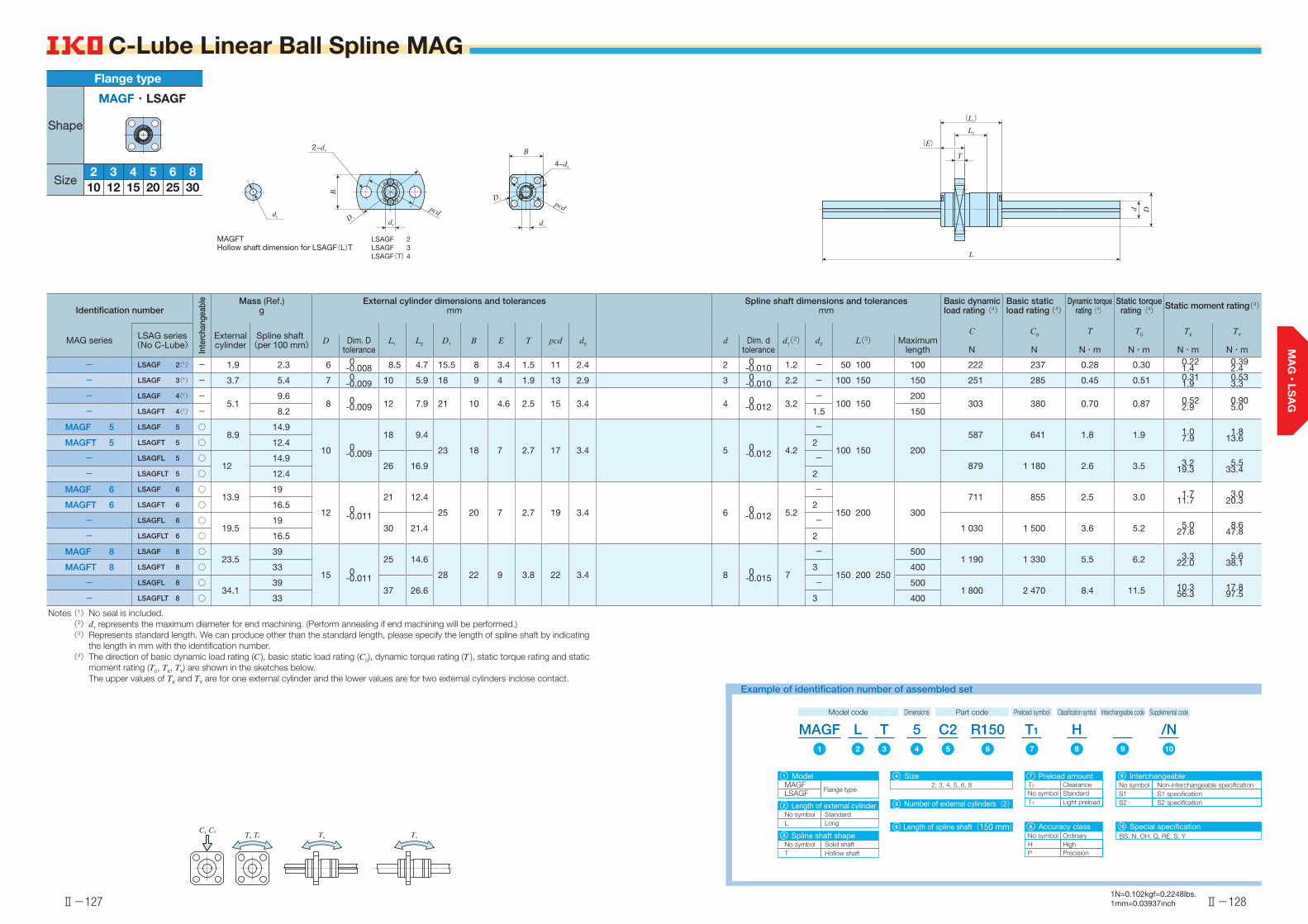
C-Lube Linear Ball Spline MAG
C, C0
T, T0 TYTX
Identification number
Inte
rcha
ngea
ble Mass (Ref.)
gExternal cylinder dimensions and tolerances
mmSpline shaft dimensions and tolerances
mmBasic dynamic load rating(4)
Basic static load rating(4)
Dynamic torquerating(4)
Static torquerating(4) Static moment rating(4)
MAG series LSAG series(No C-Lube)
External cylinder
Spline shaft(per 100 mm) L1 L2 D1 B E T pcd d3 d1(2) d2
C
N
C0
N
T
N・m
T0
N・m
TX
N・m
TY
N・mD Dim. D
toleranced Dim. d
toleranceL(3) Maximum
length
- LSAGF 2(1) - 1.9 2.3 6 0-0.008 8.5 4.7 15.5 8 3.4 1.5 11 2.4 2 0
-0.010 1.2 - 50 100 100 222 237 0.28 0.30 0.221.4
0.392.4
- LSAGF 3(1) - 3.7 5.4 7 0-0.009 10 5.9 18 9 4 1.9 13 2.9 3 0
-0.010 2.2 - 100 150 150 251 285 0.45 0.51 0.311.9
0.533.3
- LSAGF 4(1) -5.1
9.6 8 0
-0.009 12 7.9 21 10 4.6 2.5 15 3.4 4 0-0.012 3.2
-100 150
200 303 380 0.70 0.87 0.52
2.90.905.0- LSAGFT 4(1) - 8.2 1.5 150
MAGF 5 LSAGF 5 ○8.9
14.9
10 0-0.009
18 9.4
23 18 7 2.7 17 3.4 5 0-0.012 4.2
-
100 150 200
587 641 1.8 1.9 1.07.9
1.813.6MAGFT 5 LSAGFT 5 ○ 12.4 2
- LSAGFL 5 ○12
14.926 16.9
- 879 1 180 2.6 3.5 3.2
19.35.5
33.4- LSAGFLT 5 ○ 12.4 2
MAGF 6 LSAGF 6 ○13.9
19
12 0-0.011
21 12.4
25 20 7 2.7 19 3.4 6 0-0.012 5.2
-
150 200 300
711 855 2.5 3.0 1.711.7
3.020.3MAGFT 6 LSAGFT 6 ○ 16.5 2
- LSAGFL 6 ○19.5
1930 21.4
-1 030 1 500 3.6 5.2 5.0
27.68.6
47.8- LSAGFLT 6 ○ 16.5 2
MAGF 8 LSAGF 8 ○23.5
39
15 0-0.011
25 14.6
28 22 9 3.8 22 3.4 8 0-0.015 7
-
150 200 250
5001 190 1 330 5.5 6.2 3.3
22.05.6
38.1MAGFT 8 LSAGFT 8 ○ 33 3 400
- LSAGFL 8 ○34.1
3937 26.6
- 5001 800 2 470 8.4 11.5 10.3
56.317.897.5- LSAGFLT 8 ○ 33 3 400
Notes (1) No seal is included.(2) d1 represents the maximum diameter for end machining. (Perform annealing if end machining will be performed.)(3) Represents standard length. We can produce other than the standard length, please specify the length of spline shaft by indicating
the length in mm with the identification number.(4) The direction of basic dynamic load rating (C ), basic static load rating (C0), dynamic torque rating (T ), static torque rating and static
moment rating (T0, TX, TY) are shown in the sketches below. The upper values of TX and TY are for one external cylinder and the lower values are for two external cylinders inclose contact.
(L1)
(E)
L2
T
L
d D
LSAGF 2LSAGF 3LSAGF(T) 4
MAGFTHollow shaft dimension for LSAGF(L)T
pcd
2−d3
B
d1
D 1
B
4−d3
d1
pcdD 1
d2
1N=0.102kgf=0.2248lbs.1mm=0.03937inch
52 3302520151210864
Flange type
MAGF・LSAGF
Shape
Size
MAGFModel
Flange typeLSAGFNumber of external cylinders(2)
Size2, 3, 4, 5, 6, 8
Length of spline shaft(150 mm)
S1S2
No symbolNo symbol
Light preloadStandard
Special specificationBS, N, OH, Q, RE, S, YNo symbol
Accuracy class
H HighOrdinary
P Precision
Length of external cylinderStandardLongL
No symbol
Spline shaft shapeSolid shaftHollow shaftT
No symbol
Clearance
Example of identification number of assembled set
Model code Dimensions Part code Preload symbol Classification symbol Supplemental codeInterchangeable code
1
2
3
Interchangeable
S2 specificationS1 specificationNon-interchangeable specification
9Preload amount
T1
T0
7
108
MAGF1
T1
7
L2
/N109
H8
C25
54
T3
R1506
4
5
6

Ⅱ-129 Ⅱ-130
C-Lube Linear Ball Spline MAG
LSAGF(L) 30
C, C0
T, T0 TYTX
C, C0T, T0
Identification number
Inte
rcha
ngea
ble Mass (Ref.)
gExternal cylinder dimensions and tolerances
mmSpline shaft dimensions and tolerances
mmBasic dynamic load rating(3)
Basic static load rating(3)
Dynamic torquerating(3)
Static torquerating(3) Static moment rating(3)
MAG series LSAG series(No C-Lube)
External cylinder
Spline shaft(per 100 mm) L1 L2 D1 B E T pcd d3 d1(1) d2
C
N
C0
N
T
N・m
T0
N・m
TX
N・m
TY
N・mD Dim. D
toleranced Dim. d
toleranceL(2) Maximum
length
MAGF 10 LSAGF 10 ○45
60.5
19 0-0.013
30 18.2
36 28 10 4.1 28 4.5 10 0-0.015 8.9
-
200 300 600
1 880 2 150 10.9 12.5 7.041.5
12.171.9MAGFT 10 LSAGFT 10 ○ 51 4
- LSAGFL 10 ○70.1
60.547 34.9
- 2 850 4 040 16.6 23.4 22.7
11539.3
200- LSAGFLT 10 ○ 51 4
MAGF 12 LSAGF 12 ○59
87.5
21 0-0.013
35 23
38 30 10 4 30 4.5 12 0-0.018 10.9
-
200 300 400 800
2 180 2 690 14.8 18.3 10.659.1
18.3102MAGFT 12 LSAGFT 12 ○ 66 6
- LSAGFL 12 ○91.8
87.554 42
- 3 220 4 850 21.9 33.0 32.2
15755.7
272- LSAGFLT 12 ○ 66 6
- LSAGF 15 ○ 77111 23 0
-0.01340 27
40 31 11 4.5 32 4.5 13.6 0-0.018 11.6
-200 300 400 1 000
4 180 6 070 31.3 45.6 27.8152
33.2181
- LSAGFL 15 ○ 128 65 52 - 6 400 11 500 48.0 86.5 94.0449
112535
- LSAGF 20 ○ 150202 30 0
-0.01650 33
46 35 14 5.5 38 4.5 18.2 0-0.021 15.7
- 300 400 500600 1 000
6 600 9 040 66.0 90.4 48.6288
58.0343
- LSAGFL 20 ○ 218 71 54 - 9 270 15 100 92.7 151 127650
151774
- LSAGF 25 ○ 255310 37 0
-0.01660 39.2
57 43 17 6.6 47 5.5 22.6 0-0.021 19.4
- 300 400 500600 800 1 200
11 200 14 300 139 178 92.8551
111656
- LSAGFL 25 ○ 371 84 63.2 - 15 400 23 200 193 290 2291 190
2731 420
- LSAGF 30 ○ 476450 45 0
-0.01670 43
65 50 21 7.5 54 6.6 27.2 0-0.021 23.5
- 400 500 600700 1 100 1 200
15 400 19 400 231 292 147874
1761 040
- LSAGFL 30 ○ 680 98 71 - 21 300 31 600 320 474 3641 900
4342 260
Notes (1) d1 represents the maximum diameter for end machining. (Perform annealing if end machining will be performed.)(2) Represents standard length. We can produce other than the standard length, please specify the length of spline shaft by indicating
the length in mm with the identification number.(3) The direction of basic dynamic load rating (C ), basic static load rating (C0), dynamic torque rating (T ), static torque rating and static
moment rating (T0, TX, TY) are shown in the sketches below. The upper values of TX and TY are for one external cylinder and the lower values are for two external cylinders inclose contact.
(L1)
(E)
L2
T
L
d D
LSAGF(L) 30MAGFTHollow shaft dimension for LSAGF(L)T
D 1
d1
B
pcd
4−d3
B
4−d3
d1
pcdD 1
d2
1N=0.102kgf=0.2248lbs.1mm=0.03937inch
10, 12, 15, 20, 25, 30
MAGF R300C212 /NH
MAGFModel
Flange typeLSAGFNumber of external cylinders(2)
Size
Length of spline shaft(300 mm)
S1S2
No symbolNo symbolLight preloadStandard
Special specificationBS, N, OH, Q, RE, S, YNo symbol
Accuracy class
H HighOrdinary
P Precision
T
Length of external cylinderStandardLongL
No symbol
Spline shaft shapeSolid shaftHollow shaftT
No symbol
Example of identification number of assembled set
Model code Dimensions Part code Preload symbol
T1
Classification symbol Supplemental codeInterchangeable code
1
2
3
Interchangeable
S2 specificationS1 specificationNon-interchangeable specification
9Preload amount
T1
7
108
1 72 1098543 6
4
5
6
52 3302520151210864
Flange type
MAGF・LSAGF
Shape
Size
Related Documents