ELSEVIER Solar Energy Materials and Solar Cells 43 (1996) 203-222 ~Sdw~ Limiting efficiencies for photovoltaic energy conversion in multigap systems Antonio Marti *, Gerardo L. Arafijo Instituto de Energ(a Solar, UniversidadPolitdcnica de Madrid, E.T.S.L de Telecoraunicaci6n, Ciudad Universitaria, 28040Madrid, Spain Received 9 September 1995; revised 1 February 1996; accepted 25 March 1996 Abstract Multigap systems are better matched to the sun's spectrum than single gap systems and are, therefore, more efficient as photovoltaic converters. This paper reviews the different thermody- namic approaches used in the past for computing the limiting efficiency for the conversion of solar energy into work. Within this thermodynamic context, the limit ranges from 85.4% to 95.0% depending on the assumptions made. Detailed balance theory provides a more accurate model of the photovoltaic converter. It leads to a limit of 86.8% for a system with an infinite number of cells, as already pointed out by other authors. In this work, however, we use the concepts of angle and energy restriction to emphasize that this limit is independent of the light concentration. Systems with a finite number of ceils are also studied and their limiting efficiency is found to be higher than previously reported. Data for AM1.5 Direct spectrum, never computed before, are included. Keywords: Photovoltaics; Multigap; Limiting efficiency; Thermodynamics; Solar cells 1. Introduction A topic of interest in photovoltaics is the elucidation of the maximum efficiency of the photovoltaic conversion processes. A review of the literature shows that the different studies can be grouped in two main categories. In the first, authors studied the limiting efficiency of single gap solar cells. The present authors devoted a study to this subject [1]. In the second category, the limiting efficiency of multigap systems was used as a * Corresponding author. Email: [email protected] 0927-0248/96/$15.00 Copyright © 1996 Elsevier Science B.V. All rights reserved. PH S0927-0248(96)00015-3

Welcome message from author
This document is posted to help you gain knowledge. Please leave a comment to let me know what you think about it! Share it to your friends and learn new things together.
Transcript

ELSEVIER Solar Energy Materials and Solar Cells 43 (1996) 203-222
~ S d w ~
Limiting efficiencies for photovoltaic energy conversion in multigap systems
Antonio Marti *, Gerardo L. Arafijo Instituto de Energ(a Solar, Universidad Politdcnica de Madrid, E.T.S.L de Telecoraunicaci6n, Ciudad
Universitaria, 28040 Madrid, Spain
Received 9 September 1995; revised 1 February 1996; accepted 25 March 1996
A b s t r a c t
Multigap systems are better matched to the sun's spectrum than single gap systems and are, therefore, more efficient as photovoltaic converters. This paper reviews the different thermody- namic approaches used in the past for computing the limiting efficiency for the conversion of solar energy into work. Within this thermodynamic context, the limit ranges from 85.4% to 95.0% depending on the assumptions made. Detailed balance theory provides a more accurate model of the photovoltaic converter. It leads to a limit of 86.8% for a system with an infinite number of cells, as already pointed out by other authors. In this work, however, we use the concepts of angle and energy restriction to emphasize that this limit is independent of the light concentration. Systems with a finite number of ceils are also studied and their limiting efficiency is found to be higher than previously reported. Data for AM1.5 Direct spectrum, never computed before, are included.
Keywords: Photovoltaics; Multigap; Limiting efficiency; Thermodynamics; Solar cells
1. I n t r o d u c t i o n
A topic of interest in photovoltaics is the elucidation of the maximum efficiency of the photovoltaic conversion processes. A review of the literature shows that the different studies can be grouped in two main categories. In the first, authors studied the limiting efficiency of single gap solar cells. The present authors devoted a study to this subject [1]. In the second category, the limiting efficiency of multigap systems was used as a
* Corresponding author. Email: [email protected]
0927-0248/96/$15.00 Copyright © 1996 Elsevier Science B.V. All rights reserved. PH S0927-0248(96)00015-3

204 A. Marff, G.L Arafijo / Solar Energy Materials and Solar Cells 43 (1996) 203-222
way to approach the absolute limit of photovoltaic energy conversion (PVEC) and this is the category to which this paper belongs.
Although the question of the limiting efficiency of PVEC is one that ought to have a unique answer, different figures appear in the literature as will be detailed later. Sometimes, authors made different assumptions and used different approaches leading them to different results. Most of the time, the new figure arose from the consideration of a new aspect previously overlooked which progressively completed our understanding of the photovoltaic processes.
Two complementary approaches have been used in the past to answer the question of the limiting efficiency. The first, based on thermodynamics, is independent of the nature of the converter and is briefly reviewed in this paper ~ in the first section. The other, described in Section 2, is based on detailed balance arguments. It uses a more refined model that makes some assumptions about the nature of the converter: the solar cell. In Section 3, we make some remarks about the differences, concerning the limiting efficiency, between a system with an infinite number of cells and a system with a finite number of cells. The limiting efficiency for the finite system is higher than previously reported.
2. A brief thermodynamic review
Thermodynamics is the natural framework for the study of the upper bounds of the efficiency of those processes involving energy conversion: heat into mechanical work, light into heat, heat into chemical energy, etc., and in the case we are now dealing with, light into electrical work. By using thermodynamics, we claim there is a unique and definitive answer to the problem being analyzed. However, when reviewing the litera- ture, some confusion appears because different figures for the limiting efficiency of PVEC are reported, all obtained by using thermodynamic concepts.
Analyses involving thermodynamics represent an attempt to obtain a result that is independer~t of the nature of the converter. To understand the different hypotheses and definitions that lead to different results, we find the general description given by Landsberg of an energy converter in [2] very useful. Indeed, most of the discussion and explanation that follows has arisen from Ref. [3].
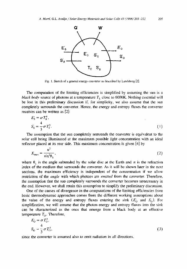
Landsberg's description of a general converter is graphically sketched in Fig. 1. The converter, assumed to be at a temperature T c, receives photons characterized by energy and entropy fluxes E~ and S~ respectively from an arbitrary source. In the general case, it also emits photons characterized by an energy and entropy fluxes, E~ and S~, towards a sink. The general converter produces heat (Q') and work (W') and, if the process is not steady-State, has internal energy and entropy varying at a rate E~ and S~, respectively. However, from now on, we will assume all processes are steady-state so that E~ and S~ are zero.
If these interchange processes occur irreversibly, we use Sg to represent the corre- sponding total rate of entropy increase. However, we shall assume for the moment that the interchange processes occur reversibly so that the additional entropy due to irreversibilities, S'g, will be taken as zero.
A. Mart[, G.L Arafijo / Solar Energy Materials and Solar Cells 43 (1996) 203-222 205
Q ' W '
E ~ E'o S's ~ S ' o
Fig. I. Sketch of a general energy converter as described by Landsberg [2].
The computation of the limiting efficiencies is simplified by assuming the sun is a black body source of photons at a temperature T s close to 6000K. Nothing essential will be lost in this preliminary discussion if, for simplicity, we also assume that the sun completely surrounds the converter. Hence, the energy and entropy fluxes the converter receives can be written as [2]:
4 = -5 ( )
The assumption that the sun completely surrounds the converter is equivalent to the solar cell being illuminated at the maximum possible light concentration with an ideal reflector placed at its rear side. This maximum concentration is given [4] by
n 2
gma x sin20s (2)
where 0 s is the angle subtended by the solar disc at the Earth and n is the refraction index of the medium that surrounds the converter. As it will be shown later in the next sections, the maximum efficiency is independent of the concentration if we allow restriction of the angle with which photons are emitted from the converter. Therefore, the assumption that the sun completely surrounds the converter becomes unnecessary in the end. However, we shall retain this assumption to simplify the preliminary discussion.
One of the causes of divergence in the computations of the limiting efficiencies from basic thermodynamic approaches comes from the different working assumptions about the value of the energy and entropy fluxes entering the sink (E 0 and So). For simplification, we will assume that the photon energy and entropy fluxes into the sink can be characterized as the ones that emerge from a black body at an effective temperature T O . Therefore,
4 S o = -~,,-r 8, (3)
since the converter is assumed also to emit radiation in all directions.

206 A. Martf, G.L. Ara~jo / Solar Energy Materials and Solar Cells 43 (1996) 203-222
Two balance equations corresponding to the energy and entropy conservation can now be written:
E' s=Q' + W' + E'o,
TcS' s = Q' + TcS' o, (4)
and, hence,
Q ' = rcS' s - TcS'o,
w ' = El - r c s l + r c s ; - Eb. (5)
Two main definitions for efficiency now become available:
W'
~71 = El _ E~) (6a)
W' n2= (6b)
The first one corresponds to the ratio between the power the converter produces as work and the power it consumes. Notice that the energy it consumes is the difference between the power received from the sun and the power emitted. The second definition is the definition of efficiency commonly used in photovoltaics: the ratio between the power extracted from the cell and the power received from the sun. This difference in definitions has been the source of some confusion [5].
With the first definition, Eq. 6a, the efficiency increases with T O (see Fig. 2). The maximum efficiency is, therefore, achieved when T o = T s (point A in Fig. 2) since, at higher temperatures, W' becomes negative which means that the surroundings are doing work on the system instead of the vice versa. At this point, the maximum efficiency
r/
Cl
/ ! I
P
To
Fig. 2. Qualitative behaviour of the power W', heat Q' and the efficiencies defined by Eq. (6) as a function of the emission temperature T o. Curve labelled as ~lt)v corresponds also to definition 2 but, following [3], does not assume the photovoltalc process as reversible. See Table 1 for identification of the dot labels.

A. Mart[, G.L Araftjo / Solar Energy Materials and Solar Cells 43 (1996) 203-222 207
ob ta ined is the same as the ef f ic iency o f a C a m o t engine [6] opera t ing be tween heat reservoirs at the sun ' s and Ear th ' s temperature :
Tc ~71,MAX = 1 Ts" (7)
Notice , however , that a l though the ef f ic iency is m a x i m u m when T o = T s, then W ' = 0 which is of no pract ica l use. In this context , def ini t ion 2 in (6) is preferred. Subst i tut ing (5) and (1) into Eq. (6b), the fo l lowing equat ion is obta ined:
4 4 T c + - 1 (8 )
172 = 1 -- "3" -~" s ~3 T O t ~ ' s ] "
Eq. (8) reaches its m a x i m u m for T o = T c g iv ing then:
! [ 5 / 4 4 T c + (9 )
= 3 Ts l '
which cor responds to the Landsbe rg l imi t ing ef f ic iency [2], poin t B in Fig. 2. Not ice that with def ini t ion 6b, max imiz ing the ef f ic iency is equiva lent to max imiz ing W' , Hence, when T O --- T c , W ' also is max imum. Henry [7] a s sumed that the m a x i m u m eff ic iency was for T o = 0 since, intui t ively, for this value no emiss ion losses occur. He found then that:
4 T c n'2,MAX = 1 - - - - - - , ( 1 0 )
3 T s
which cor responds to poin t C in Fig. 2. However , when en t ropy f lux conserva t ion is taken into account as in L a n d s b e r g ' s
approach descr ibed above, it is found that for T o = T c , a l though some emiss ion losses exist , these losses are compensa t ed because the Q' losses are lower than in the case in which T O = 0. Table 1 includes the main results that have been descr ibed above. Notice, however , that in this discussion, still all the processes have been as sumed reversible . The i r revers ib le nature of photovol ta ic energy convers ion has been po in ted out by several
Table 1 Summary of the main results about the limiting efficiency of the photovoltaic energy conversion considering thermodynamic approaches. Results refer to the sun assumed as a black body at T s = 6000K and Earth at T c = 300K. Dots refer to Fig. 2
Author Ref. Def. S'g T O Max. efficiency Result
Carnot DOT A [6] "qj 0 T s 1 - r~ 95.0% Henry DOT C [7] "q2 0 0 1 - 4_ r~ 93.3%
3 T s
4T~.~ I T~ 4 Landsberg DOT B [2] "q2 0 T C 1 - ~ r, + 7( r, ) 93.3% A. De Vos and Pauwels DOT D [3] "q2 (I-1) TDV = 2540K (1-2) 85.4%
s'~ 2 4 ~ - ' ~ ' = o sr~ + ~ ] ( I -1) r_~ r 4
nnv = (1 - ro)[1 - ( ~ ) ] (1-2)

208 A. MarE, G.L Arafijo / Solar Energy Materials and Solar Cells 43 (1996) 203-222
authors [3,8-11] and a detailed discussion is outside the scope of this paper. In any case, the computation of the entropy generation rate S'g requires additional hypotheses, some of them based on assumptions from the detailed balance theory. They will lead us to the curve labelled as ~qDv in Fig. 2 as will discussed in the next section.
3. The detailed balance approach for a multigap system
Previous results were obtained assuming that the entropy generation rate, S'g, was zero. Since no assumption was made about the nature of the converter, this hypothesis allowed us to compute an upper bound for the efficiency. We shall now present a different approach.
If some appropriate assumptions are made about the nature of the converter, the work rate W' can be computed directly. In our case, the converter will be a system of one or more solar cells and the framework of the detailed balance theory [12,13] will provide the necessary set of assumptions. This was reviewed in detail in other papers [1,14] at the time that the limiting efficiency of a system constituted by one cell was studied. For the convenience of the reader, we will, briefly summarize here these assumptions and the conclusions they lead us to.
The basic structure of the solar cell considered is illustrated in Fig. 3b. It consists in a semiconductor slab sandwiched between some regions p+ and n + arbitrarily thin. The following assumptions are made regarding the operation of the cell:
(a) Only radiative recombination processes take place. When describing the radiative generation-recombination mechanisms, photon absorption and spontaneous and stimu-
oll
p+ r l +
(a) (b) Fig. 3. (a) Elementary geometry for illuminating the cells in a concentration system. 0 s is the angle of the sun
sphere when it is seen from Earth, 0 x is the maximum angle with which photons reach the cell after the concentrator, 0 E is the angle with which photons are emitted from the cell. (b) Basic solar cell structure used
in the formulation of the detailed balance approach.

A. Marff, G.L. Ara(tjo / Solar Energy Materials and Solar Cells 43 (1996) 203-222 209
lated photon emission processes are considered. In addition, each photon is assumed to produce only one electron-hole pair when absorbed and vice versa: each electron-hole pair produces only one photon when recombined. Recently, attention has been given to the possibility that one photon generates two (or more) electron-hole pairs by means of optically induced impact ionization [15-17]. In this work, however, the one to one hypothesis will still be considered as the most likely absorption process. Furthermore, from the point of view of the limiting efficiency, it has been recognized [18] that the maximum efficiency of the hot carrier solar energy converter is essentially equivalent to that of an infinite stack of one to one solar cells.
(b) Carrier mobility is assumed to approach infinity so ohmic losses are neglected. Pseudo-Fermi level splitting becomes constant through the device and equal to the external voltage applied.
With these hypothesis, the current versus voltage characteristic of the solar cell was proved in [1] to be given by:
I = q( FA8 s -- FEM), (1 1)
where FAB s and FE~ are the number of photons absorbed and emitted per unit of time in the cell, respectively. These values can be computed from the following relationships:
FAB S = q fabs cos 0 d Ed $2 d S
2 E 2 1 0 < 0 x h3c 2 E
exp - 1 ~ r s
2 E 2 1
h3c 2 E
exp k T c
b S
7 r / 2 > 0 > 0 x
- 1
(12)
where the equation for 0 < 0 x (see Fig. 3a for the definition of the angle 0) corresponds to photons coming from the sun characterized as a black body at a temperature Ts; and the equation for 0 > 0 x corresponds to photons coming from the environment which is also taken to be at temperature T c. ~ is the solid angle that 0 sustains. The other term in Eq. (11) is given by
= f e b ( V ) c o s 0d Ed ~2dS FEU
2E: 1 b ( V ) = h3c2 E - q V (13)
exp - - 1 k:r c
The terms a and e in (12) and (13) are the absorptieity and the emissizity, respectively, and in the most general case they have angular dependence. In principle, there is no a priori reason to assume e = a under nonequilibrium conditions. However, in the framework of [1], it was proved that e = a still holds in nonequilibrium conditions providing hypotheses " a - b " are satisfied. It has to be emphasized that, when the
210 A. Martl, G.L Arafijo / Solar Energy Materials and Solar Cells 43 (1996) 203-222
current voltage characteristic of the solar cell is written as in Eqs. (11) to (13), photon recycling effects have already been taken into account.
Given the solar spectrum, the usage of only one cell does not provide the maximum possible efficiency since, for example, no power is extracted from photons with energies lower than the bandgap energy. Two solar cells can better match the solar spectrum, and when the scheme is taken to the limit, an infinite number of cells provides the best approach [19-21].
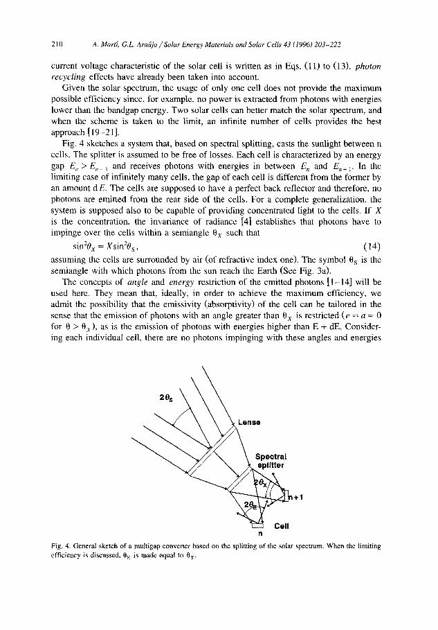
Fig. 4 sketches a system that, based on spectral splitting, casts the sunlight between n cells. The splitter is assumed to be free of losses. Each cell is characterized by an energy gap E, > E,_ i and receives photons with energies in between E n and En+ 1. In the limiting case of infinitely many cells, the gap of each cell is different from the former by an amount d E. The cells are supposed to have a perfect back reflector and therefore, no photons are emitted from the rear side of the cells. For a complete generalization, the system is supposed also to be capable of providing concentrated light to the cells. I f X is the concentration, the invariance of radiance [4] establishes that photons have to impinge over the cells within a semiangle 0 x such that
sinZ0x = Xsin20s, (14)
assuming the cells are surrounded by air (of refractive index one). The symbol 0 s is the semiangle with which photons from the sun reach the Earth (See Fig, 3a).
The concepts of angle and energy restriction of the emitted photons [1-14] will be used here. They mean that, ideally, in order to achieve the maximum efficiency, we admit the possibility that the emissivity (absorptivity) of the cell can be tailored in the sense that the emission of photons with an angle greater than 0 x is restricted (e = a = 0 for 0 > 0x), as is the emission of photons with energies higher than E + dE. Consider- ing each individual cell, there are no photons impinging with these angles and energies
20s
" ~ / ' ~ \ Spectral ~ 1+1
Cell n
Fig. 4. General sketch of a multigap converter based on the splitting of the solar spectrum. When the limiting efficiency is discussed, 0 E is made equal to 0×.
A. Mart[, G.L. Ara{~jo / Solar Energy Materials and Solar Cells 43 (1996) 203-222 211
so there is no need to have an absorptivity (emissivity) equal to unity in these ranges and it can be set equal to zero. By doing this, the photogenerated current of the cell is not affected but, the emission of photons, and, therefore, the losses are reduced, and the efficiency increased. Elsewhere, the absorptivity (emissivity) will be assumed equal to unity. Readers interested in a discussion about when the assumption of unit absorptivity does not lead to maximum efficiency can refer to [l].
With these considerations, and taking the number of ceils to infinity, if V(E) is the operating voltage of the cell with gap E, the elemental power extracted from this cell per unit of area is
dw' = sin2Oxf( E ,V )d E, (15)
with
2rr 1 1 VdE, (16)
- 1 exp ~ - 1
where the integration in the solid angle has been carried out already. The total power is obtained by integrating (15) in energies:
w' ; sin2Oxf f ( E , V ) d E. (17)
The efficiency, in the photovoltaic sense, is obtained by applying definition 6b. Therefore,
sin2Oxfy(e,V)de ff(E,V)de = ( i s )
"02 = XsinZ0s o" Ts 4 or T 4 '
where Eq, (14) has been used. This proves that the efficiency is independent of the concentration providing the angle of emission of photons is restricted to that of the incoming light as assumed above (0 E = 0 x in Fig. 3a).
Two different approaches have been used in the past to maximize (18). In the first one, described by De Vos and Pauwels [3], for illustrative and simplifying purposes, the operating voltage of each cell was linked to the photon energy in order to characterize the emission of photons from the system by means of an effective temperature To:
E - q V E
k-----~c = k-~o. (19)
Then, Eq. (18) resulted in Eq. (I-2) in Table 1 and T o was optimized to maximize the efficiency. The result was an optimum efficiency of 85.4% [3] which corresponds to an equivalent temperature T o = TDV = 2540K (Point D in Fig. 2). For their computations they used maximum concentration. In this paper, however, it is emphasized that it is not necessary to assume that the cell operates at the maximum concentration to obtain the maximum efficiency providing that the angle of emission of photons is restricted

212 A. Martl, G.L. Arafijo / Solar Energy Materials and Solar Cells 43 (1996) 203-222
(0 E = 0x). Therefore, the figure 85.4% is independent of the concentration. In any case, the simplification in Eq. (19) allowed De Vos and Pauwels to clearly illustrate how the photovoltaic conversion should be considered as an irreversible processes at the operat- ing voltage that corresponds to the maximum efficiency. With some additional calcula- tions involving entropy flux conservation, they computed the entropy generation S'g due to the irreversibilities in the conversion processes (Eq. (I-1) in Table 1, Eq. (31) in Ref. [3]). These results have also been included in the summary of Table 1 for comparison with the other thermodynamic approaches discussed in Section 1. In later discussions [9-11 ], the nature of the irreversibilities was described more and they were associated to the coupling of the converter to the external world by means of the interchange of both energy and matter (endoreversible processes).
A slightly more complicated but otherwise more realistic approach to maximizing (18), also described in [3], consists in maximizing the operating voltage for each individual cell so that V = Vm(E) with Vm(E) satisfying
0 -~f( E,Vm(E)) = 0. (20)
Computing (18) with V = Vm(E), we also obtained the maximum efficiency as 86.8% with the novelty that this figure is independent of the concentration providing that 0 E = 0 x, as mentioned already.
For the discussion above, the splitting system sketched in Fig. 4 has been used as the starting point for simplicity. Some objections to the model can arise from the fact that an additional external element, the splitter, has been introduced in the system and that this splitter has been assumed to be free of losses. It can be proved (see next section) that a stacked system as the one sketched in Fig. 5, which will be discussed in the next two sections, leads to the same equations (15 to 18) when the number of cells increases to infinity and therefore, to the same value of the limiting efficiency without the necessity of an external element. However, this system has interesting features regarding the limiting efficiency when the number of cells considered is finite.
4. Limiting efficiency of a system with a finite number of cells
In a stacked system, N cells are ordered by decreasing gap as sketched in Fig. 5a. The first (n = 1) is the cell with the lowest bandgap. It is, therefore, placed at the bottom of the stack. Sunlight travels from left to right. A perfect back reflector is placed at the rear side of the last cell to prevent emission losses in that direction.
At cell n + 1, photons with energies lower than the gap of the cell, E n + l, are allowed to pass through; then, the cell n absorbs those photons from the sun spectrum with energies E,+ l > E > E,. We will analyze now two different cases differing in the way the radiative losses are handled.
In case " a " , Fig. 5a, due to radiative recombination, cell n emits photons producing some energy losses for the cell. However, cell n + 1 and cell n - 1 benefit from these luminescence losses in cell n since cell n - 1 can collect all the photons that cell n

A. MarE, G.L. Ara{ijo / Solar Energy Materials and Solar Cells 43 (1996) 203-222 213
(a)
U')
ILl
cell
I
I
N
A,n+
)f Arn I
)fL,n
En
v
ibrA,n / I /
blA,n., (/?; / / j ' ) i l l
I i .i
. ' f ' , ' /
n + l n n-1 1
(b)
Ul
r e f l e c t o r - - . ~ bfR,n brR,n / / / I
, / / I
/ I ] ~,~ / / I -
/ / /
, i " 7
! E.I
cell N n + l n n-1 1
Fig. 5. Sketch of a stacked multigap system. In (a) no reflector is placed at the rear side of the cells and so, photons emitted from one cell can be absorbed by the others. In (b) a reflector is placed at the rear side. In this case, although the cells do not absorb photons from their neighbours, the radiative losses in each individual cell also decreases, In text it is discussed which approach give the maximum efficiency.
emits from the rear side and cell n + 1 can collect the portion of the photons emitted from the front side of cell n with energies higher than En÷ 1. This effect is called radiative coupling between the cells. Then, only the portion of the emitted photons with energies E n_ i < E < E, are wasted.
In case "b" , a reflector is placed at the rear side of the cells (Fig. 5b). The emission Tosses of cell n will be reduced. However, cells n - 1 and n + 1 will not benefit from

214 A. Martf, G.L. Arafijo / Solar Energy Materials and Solar Cells 43 (1996) 203-222
the luminescent photons coming from cell n as in the previous case. The following question arises: has this configuration a higher limiting efficiency than the previous configuration? The answer is " y e s " as it was anticipated in Ref. [22] for a system with two gaps. The discussion is generalized here to a higher number of gaps at the time that new results are presented.
To discuss these configurations simultaneously, we define the appropriate step function to describe the reflector at the rear side of cell n:
1(O) E > E . (21) rn = E < E.
The value " 1 " describes the situation for case b, in which reflectors are introduced, while " 0 " corresponds to case a. The absorptivity (emissivity) of cell n is given also by a step function.
[1 E > E,~ (22)
a, = E < E n
Considering the different sources for the photon radiance that cell n receives and its luminescent losses, the maximum power delivered by cell n is given by:
P. = qrrsinZOxVm,.fE(bs," + bar n(Vm,.+l) + bf .(Vm,.) + 1)
+ bL.(Vm,.) - 2bE(Vm..))d•, (23)
where I'm, x is the optimum operation voltage in cell x to achieve the maximum
Table 2 Description of the different spectral photon radiance involved in a stacked system of cells
Notation Value Meaning
bs. n (a n - a,,+ i )bs bJR,.( V,,) r,,+ ,a.b(V,,,)
b~..(V,,) r , ,anb(V , )
b~,.(V~+ i) a . ( 1 - r . + l ) a , , + t b ( V . + l ) b~,..(V._ 1 ) a,,(1 - r . ) a n _ l b ( V . _ l )
2 E 2
b(V.) a,, h3c2 e x p ( ( E - e V . ) / k r c ) - 1
b f . ( v . ) (1 - a.+ i )a .b (V . )
Coming from the sun and absorbed in cell n Emitted from cell n, reflected in reflector n + 1
and absorbed again in cell n Emitted from cell n, reflected in reflector
n and absorbed again in cell n Emitted from cell n + 1 and absorbed again in cell n
Emitted from cell n - 1 and absorbed again in cell n
Emitted from cell n. biased at V,,
Radiative losses in cell n not absorbed in any cell
(Note: Because cells with n = N + l and n = 0 does not exist, it is necessary to make a N + l = 0 , a 0 = 1 ,
VN+ i = 0 and V 0 = 0 to generalize the equations above)

A. Marff, G.L. Ara{tjo /Solar Energy Materials and Solar Ceils 43 (1996) 203-222 215
efficiency. Notice that in Eq. (23), the concept of angle restriction has been applied. The meaning of the spectral photon radiances b(Vm,.,) is summarized in Table 2.
After some manipulation, and taking into account that a , a , + 1 = a . , a , + i r,, + 1 = r,, ~ r and a,,r,,+l = r,,+l and the equations in Table 2, Eq. (23) can be rearranged as:
P,, = qrrsin2OxV.fE(( a , -- a.+ , ) b s + [a,,+ lb(Vm..+ l) - a . b ( Vm.,,)]
- r . + 1 [ b(Vm.n+ ,) - b(Vm,.) ] + a~(1 - r . ) [b(Vm. , ,_ 1) - b ( V m . . ) ] ) d E .
(24)
To achieve the maximum efficiency, the bandgap of the cells will still require optimization. Fig. 6 plots the optimum efficiency that results after the optimization of bandgaps and voltages. For comparison, we also plot the maximum efficiencies when terrestrial AM1.5 direct normal irradiance [23] is considered (instead of black body radiation at T s = 6000K) as characterizing the illumination from the sun. Also, the values corresponding to X = 1 sun and values without restricting the angle of emission (0z = 90 ° ) has been plotted. For reference, Table 3 summarizes the corresponding values. The following remarks can be pointed out:
(a) As it can be observed, both approaches (with and without reflectors) give the same result when the number of cells increase towards infinity. This result can be expected from Eq. (24) since, when number of cells tends to infinity, Vm,.+ 1 - Vm,~ ~ 0. Eq. (24) can be written as:
d P ( E ) = q~sin20x bs(E) 2 E 2 1
h3c e E - qVm( E) exp
kT
dE, (25)
which is independent of whether reflectors are used or not. Notice that Eq. (25) is identical to Eq. (15) with P playing the role of w' and, therefore, the value for the limiting efficiency for an infinite number of gaps, 86.8% for the sun assumed as a black body at T s = 6000K, is obtained as before. The figure corresponding to AM1.5 direct normal irradiance [23] has been computed here for the first time to our knowledge. It gives 85.0%. Linear interpolation of the data in Ref. [23] and trapezoidal integration have been used in the computations.
(b) However, when the number of cells is finite, the approach with reflectors gives a slightly higher efficiency than the approach without reflectors that in Ref. [20] was assumed to lead to the maximum efficiency. If we assume that the optimum voltages satisfies Vm.n+ ~ > Vm,n, this result can be proved as follows:
If the system consists of N cells and has reflectors, the power delivered is given by:
N
PwR(Vm) = ~_, P~(Vm), (26) n = l
where V m represents the set of opt imum voltages that maximizes the power and P,', is

216 A. Marti, G.L. Ara{~jo / Solar Energy Materials and Solar Cells 43 (1996) 203-222
(a) O ~timum efficiency (%)
90 . . . . . . . . . . . . . . . . . . . . . . . . . . . .
0 E=ex 80 infinite number of gaps
X=I sun eE=9oo ~ / 7 0 . . . . . . . . . . . . . . . . . . . . . . . . . . . .
60 ~
60
4ff
aft
2C
~ . ~ X = l s u n
~ - ~ e E = 9 0 o
(Black body 6000 K) , I I
2 3
Number of gaps
(b)
Optimum efficiency (%) 90
80 _-0 E=0x ~' infinite number of gaps
70-X=1 sun ( ~ E = 9 0 ° / . . . . . . /
. . . . . . . - 2 = = . . . . . . . . . . . . . / 60 ~ "
6o, . . . . i - " " ~-=1 sun i
40 - . . - 0E=90o
30 (AM1.5 normal direct)
20 L 2 3
Number of gaps
Fig. 6. Maximum efficiency as a function of the number of cells: (a) for the sun assumed as a black body at 6000K, (b) for AM1.5 direct normal irradiance [23]. In both cases, dots marked as " + " corresponds to the case with reflectors (illustrated in Fig. 5a) and dots marked as " X " to the case without reflectors (Fig. 5b). Both values are very close but the one corresponding to the case with reflectors is slightly higher.
g i v e n b y Eq . (24) w i t h the a p p r o p r i a t e s v a l u e s fo r r (Eq . (21)) . C o n v e r s e l y , i f t he
s y s t e m has n o r e f l e c t o r s , t he m a x i m u m d e l i v e r a b l e p o w e r is g i v e n by: N
PNR(Vm) = ~ P . ( V m ) , ( 2 7 ) n = l

A. Martf, G.L. Ara{tjo / Solar Energy Materials and Solar Cells 43 (1996) 203-222 217
Tab le 3
O p t i m u m ef f ic iency and b a n d g a p s for mul t igap sys tems wi th d i f ferent n u m b e r o f cells for the sun a s s u m e d as
a b l ack body at 6 0 0 0 K and for A M 1.5 d i rec t n o r m a l i r radiance [23] ( table be low) . The va lues o f the e f f ic iency
are plot ted in Fig. 6. " R e f l e c t o r s " m e a n s w h e t h e r back ref lec tors h a v e been p laced at the rear s ide o f all the
cel ls in the s tack or not. Las t cell in the s tack a lways has a back reflector. The case labeled as " ' M a x i m u m
c o n c e n t r a t i o n " is equ iva l en t a lso to the case o f opera t ion at one sun w h e n the ang le o f the emi t t ed photons
f r o m the cell is res t r ic ted to that o f the i n c o m i n g pho tons f r o m the sun
N. cells Descr ip t ion Ref lec tors? O p t i m u m gaps ( eV) E f f (%)
E l E 2 E3 E4
(Black body at 6 0 0 0 K )
1 sun, no angu l a r restr ic t ion Yes 1.31 - - - 3 t .0
1 1 sun no angu la r res t ic t ion N o 1.31 - - - 31 .0
M a x i m u m concen t ra t ion Yes 1.11 - - - 40.8
M a x i m u m concent ra t ion N o 1.11 - - - 40.8
1 sun, no angu la r restr ic t ion Yes 0.98 1.87 - - 42 .9
2 1 sun no angu la r rest ict ion N o 0.98 1.88 - - 42 .7
M a x i m u m concen t ra t ion Yes 0.77 1.70 - - 55.9
M a x i m u m concent ra t ion N o 0.78 1.71 - - 55.6
1 sun, no angu la r res t r ic t ion Yes 0.82 1.44 2.26 - 49.3
3 1 sun no angu la r rest ict ion N o 0.83 1.45 2.26 - 49.1
M a x i m u m concen t ra t ion Yes 0.62 1.26 2.10 - 63.8
M a x i m u m concent ra t ion N o 0.63 1.27 2.11 - 63.5
1 sun, no angu la r res t r ic t ion Yes 0.72 1.21 1.77 2.55 53.3
4 l sun no angu l a r rest ict ion N o 0.73 1.23 1.78 2.56 53 .0
M a x i m u m concen t ra t ion Yes 0 .52 1.03 1.61 2.41 68.8
M a x i m u m concen t ra t ion N o 0.53 1.05 1.68 2.41 68.4
I sun, no angu la r restr ic t ion Yes . . . . 69 .9
:e 1 sun no angu l a r rest ict ion N o . . . . 69.9
M a x i m u m concen t ra t ion Yes . . . . 86.8
M a x i m u m concen t ra t ion N o . . . . 86.8
( A M 1 . 5 direct no rmal i r radiance)
1 sun, no angu la r restr ic t ion Yes 1.13 - - - 32.5
1 1 sun no angu la r rest ict ion N o 1.13 - - - 32.5
M a x i m u m concen t ra t ion Yes 0 .94 - - - 44 .6
M a x i m u m concen t ra t ion N o 0 .94 - - - 44.6
1 sun, no angu la r restr ic t ion Yes 0.94 1.64 - - 44.3
2 1 sun no angu la r rest ict ion N o 0.94 1.64 - - 44.1
M a x i m u m concent ra t ion Yes 0.71 1.41 - - 59.7
M a x i m u m concen t ra t ion N o 0.71 1.41 - - 59.4
1 sun, no angu la r restr ic t ion Yes 0.71 1.16 1.83 - 50.1
3 1 sun no angu l a r rest ict ion N o 0.71 1.16 1.83 - 49 .7
M a x i m u m concent ra t ion Yes 0 .69 1.16 1.84 - 67 .0
M a x i m u m concen t ra t ion N o 0.69 1.16 1.83 - 66.6
1 sun, no angu l a r restr ic t ion Yes 0.71 1.13 1.55 2.13 54 .0
4 1 sun no angu la r rest ict ion N o 0.71 1.13 1.55 2.13 53.6
M a x i m u m concen t ra t ion Yes 0.53 1.13 1.55 2.13 71 .0
M a x i m u m concen t ra t ion N o 0.53 1.13 1.55 2.13 70.7
1 sun, no angu la r res t r ic t ion Yes . . . . 65.4
:c 1 sun no angu l a r rest ict ion N o . . . . 65.4
M a x i m u m concen t ra t ion Yes . . . . 85 .0
M a x i m u m concen t ra t ion N o . . . . 85.0

218 A. Martf, G.L. Ara~jo / Solar Energy Materials and Solar Cells 43 (1996) 203-222
Vm being the optimum set of voltages for the new arrangement and Pm given by Eq. (24) and with r = 0 in Eq. (21). Notice that, in general, V m ~ V m and, therefore,
PwR( Vm) ~ PwR( Vm), ( 2 8 )
(a) Optimum gaps (eV)
3
(b)
I
2 3 Number of gaps
Optimum gaps (eV) 2.5
2--(AM1-15.n°rmal direct) t "
i I 1 "iT, . . . . . . . . . . . . . . . . . . . . . . . . .
0.5 . . . . . . . . . . . . . . . . . . . . . . . . . . . ~- -
0 I I I i
1 2 3 4 Number of gaps
Fig. 7. (a) Optimum gaps as a function of the number of cells in the stack for the sun assumed as a black-body at T s = 600OK. Reflectors at the rear side of each cell as described in Fig. 5b have been assumed. Maximum concentration (or, equivalently, total restriction of the photons emitted from the cell) has been considered. Bars indicate the tolerance in the value of the optimum gap to keep the maximum efficiency not less than 1% of its maximum value when the other values of the gaps remain constant and equal to their optimum value (square dots). (b) The same for AM1.5 direct normal irradiance.

A. Martl, G.L. Arat~jo / Solar Energy Materials and Solar Cells 43 (1996) 203-222 219
since V m are not the optimum voltages for the configuration with reflectors. A direct calculation shows that
PwR(Vm) - PNR(Vm) =eTrsinaOxfE{rlVm,](bE.1(Vm.1) - b(O))
+ E rn(bE,n-l(gm..-l) --bE,n(Vm,n))(Vm.n-I -- Vna,.)) dE, ( 2 9 ) n=2
and, therefore, because Vm, . > Vm. ._ 1
PwR( Vm ) >-- PNR( Vm )' ( 3 0 )
which together with Eq. (28) leads to
PwR(Vm) >__ PNR(Vm), ( 3 1 )
as we wanted to show. (c) The sensitivity of the maximum efficiency with respect to the value of the
optimum bandgaps is lower as the bandgap of the cell in the stack is higher. In other words, the efficiency is more and more sensitive to the values of the gap of the cells as we consider the cells towards the bottom of the stack. This was pointed out in Ref. [24] for a system with two cells and it is illustrated here, in Fig. 7, for a system up to 4 cells. The sensitivity to the bottom cell gap is higher when AM1.5 direct normal irradiance spectrum is considered, instead of black body radiation at 6000K as illustrated in Fig. 7b.
Irradiance (Wm2mic "1) 1,200 1,100 2,1 eV
i ooij 500
400
200 l o o L I , I
- i
0 i ~ r . I
0.2 0.6
(dashed: 1 sun optimum gaps for a system of four cells)
1,13 eV I I
,, I
,,
0,71 eV
,
1 1.4 1.8 2.2 2.6 3 3.4 3.8
Wavelength (mic)
4.2
Fig. 8. Plot of the data corresponding to terrestrial direct normal solar spectral irradiance for air mass 1.5 [23]. The vertical lines show the optimum gaps for a system of four cells at one sun.

220 A. Martl, G.L. Arafijo / Solar Energy Materials and Solar Cells 43 (1996) 203-222
(d) When the sun is assumed as a black body at 6000K, the values of the optimum gaps depend on the concentration (if no angular restriction is provided) and also on whether reflectors have been placed at the rear side of the cells. The numerical results show that the optimum gaps shift towards values about 10 meV higher when no reflectors are placed in comparison with the case with reflectors. Also, when values at one sun are compared with values at maximum concentration (or total angular restric- tion) the optimum gaps shifts towards values in the range of 100-200 meV higher. However, when AM1.5 direct normal irradiance is considered, there is no such shift when the cases with reflectors and without reflectors are compared. Also, in the stacked system, when more than one cell is considered, only the optimum gap of the bottom cell is sensitive to concentration. Due to the valleys and crests that appear in the AM1.5 direct normal irradiance as a result of the atmospherical absorption, optimum gaps seems to be locked to them as illustrated in Fig. 8.
5. Conclusions
The limiting efficiency of photovoltaic energy conversion is 86.8% for the sun assumed as black body at 6000K, 85.0% if AM1.5 direct normal irradiance is consid- ered. These results are independent of the concentration providing the emission of photons can be restricted in angle to that strictly necessary to receive the photons from the sun. This limit is attributed to a system consisting of an infinite number of cells. The figures that result differ from the ones obtained from standard thermodynamic ap- proaches (93.3-95%) due to the different assumptions and even the definition of efficiency itself that is used (see Table 1). For systems consisting of a stack of a finite number of cells, the use of back reflectors increases the limiting efficiency slightly when compared to the situation without reflectors. The sensitivity of the optimum efficiency is higher for the bottom cells of the stack. Calculations involving AM1.5 direct normal irradiance have been included and show some peculiarities when compared with results corresponding to black body radiation at 6000K: the sensitivity of the efficiency to the value of the gap of the bottom cell increases and the value of the optimum gap for cells other than the bottom one does not shift significantly with concentration.
6. List of symbols
E~ E3 E~ E~ s~ s~ s~ Q, W'
Energy flux that the converter receives from the sun. Energy flux emitted from the converter to the sink. Internal energy variation rate in the converter. Energy gap of cell nth in a stacked system. Entropy flux that the converter receives from the sun. Entropy flux emitted from the converter to the sink. Internal entropy variation rate in the converter. Rate of heat conduction out of converter. Work produced per unit of time (power).

A, Martf, G.L. Arat~jo / Solar Energy Materials and Solar Cells 43 (1996) 203-222 221
T c Converter temperature. T s Temperature of the sun. T o Effective temperature for characterizing the photons emitted from the converter.
Stefan-Boltzman constant. X Light concentration. n Refraction index. 0 s Semiangle with which photons from the sun reach the Earth. 0 x Maximum semiangle with which photons impinge on the cell. 0 E Maximum semiangle for the photons emitted from the cell. 0 Angle that defines ray trajectories (Fig. 3a).
Solid angle sustained by 0. "q~ Efficiency (thermodynamic definition). ~q2 Efficiency (photovoltaic definition). FAB s Number of photons absorbed per unit of time in the cell. FEM Number of photons emitted per unit of time from the cell. a Absorptivity. e Emissivity. V Voltage. PwR Power delivered by a system with reflectors. PNR Power delivered by a system without reflectors. q Electron electric charge. h Planck's constant. c Speed of the light in vacuum. k Boltzman's constant.
Acknowledgements
This work has been partially supported by the Spanish PRONTIC under contract TIC-0778-C04-01 and "Acci6n Integrada" HB94029. The authors would like to thank Dr. P.A. Davies, Mr. P. Griffin and the reviewers for their comments and careful reading of the manuscript. Antonio wishes to remember his tutor, friend and coauthor of this paper, Gerardo, who died on 8 November 1995.
References
[1] G.L. Arafijo and A. MartL Absolute limiting efficiencies for photovoltaic energy conversion, Sol. Energy Mater. Sol. Cells 33 (1994) 213-240.
[2] P.T. Landsberg and G. Tonge, Thermodynamic energy conversion efficiencies, J. Appl. Phys. 51(7) (1980) RI-R20.
[3] A. De Vos and H. Pauwels, On the thermodinamic limit of photovoltaic energy conversion, Appl. Phys. 25 (1981) 119-125.
[4] W.R. McCluney, Introduction to Radiometry and Photometry, Ch. 5 (Artech House, Boston-London, 1994).
[5] J.E. Parrott, Thermodynamic limits to photovoltaic energy conversion, in: A. Luque and G.L. Arafijo (Eds.), Physical Limitations to Photovoltaic Energy Conversion (Adam Hilger, 1990),

222 A. Martl, G.L. Arafijo / Solar Energy Materials and Solar Cells 43 (1996) 203-222
[6] H.B. Callen, Termodinfimica, Ed. AC, Madrid, 1981. [7] C.H. Henry, Limiting efficiencies of ideal single and multiple energy gap terrestrial solar cells, J. Appl.
Phys. 32 (1980) 510-519. [8] J.E. Parrott, Thermodynamics of solar cell efficiency, Sol. Energy Mater. Sol. Cells 25 (1992) 73-85. [9] A. De Vos, Is a solar cell an endoreversible engine?, Solar Cells 31 (1991) 181-196.
[10] A. De Vos, Endoreversible Thermodynamics of Solar Energy Conversion (Oxford University Press, New York, 1992),
[11] A. De Vos, P.T. Landsherg, P. Baruch and J.E. Parrott, Entropy fluxes, endoreversibilities and solar energy conversion, J. Appl. Phys. 74(6) (1993) 3631-3637.
[12] W. Schockley and H.J. Queisser, Detailed balance limit of efficiency of p-n junction solar cells, J. Appl. Phys. 32 (1961) 510-519.
[13] J.E. Parrott, Self consistent detailed balance treatment of the solar cell, IEEE Proc. 133, Pt. J. No. 5 (1986) 314-318.
[14] G.L. Arafijo and A. Martl, Generalized detailed balance theory to calculate the maximum efficiency of solar cells, Proc. 1 lth European Photovoltaic Specialists Conf., Montreaux, 1992, pp. 142-145.
[15] P.T. Landsberg, H. Nussbaumer and G. Willeke, Band-band impact ionization and solar cell efficiency, J. Appl. Phys. 74(2) (1993) 1451-1452.
[16] J.H. Werner, R. Brendel and J. Queisser, New upper efficiency limits for semiconductor solar cells, 1st World Conf. on Photovoltaic Energy Conversion, Hawaii, 1994.
[17] J.H. Werner, S. Kolodinski and H. Queisser, Novel optimization principles and efficiency limits for semiconductor solar cells, Phys. Rev. Lett. (1994) 3851-3854.
[18] R.T. Ross and J. Nozik, Efficiency of hot carrier solar energy converters, J. Appl. Phys. 53(5) (1982) 3813-3818.
[19] A. De Vos, Detailed balance limit of the efficiency of tandem solar cells, J. Phys. D: Appl. Phys. 13 (1980) 839-846.
[20] H. Pauwels and A. De Vos, Determination of the maximum efficiency solar cell structure, Solid State Electronics 24(9) (1981) 835,843.
[21] J.E. Parrott, The limiting efficiency of an edge illuminated multigap solar cell, J. Phys. D: Appl. Phys. 12 (1979) 441-450.
[22] G.L. Arafijo and A. Martl, On the detailed balance limit of ideal multiple bandgap solar cells, Proc. 22nd IEEE Photovoltaic Specialists Conf., New York, 1991, pp. 290-294.
[23] E891-87, ASTM Standard, 1916 Race St., Philadelphia, PA 19103. [24] G.L. Arafijo and A. Martl, Limiting efficiencies of ideal multiple bandgap solar cells under concentrated
sunlight, Proc. 9th European Photovoltaic Science and Engineering Conf., Freiburg, 1991, pp. 111-114.
Related Documents