Roof S URVEY R EPORT Limited Roof Survey and Leak Investigation For Rainier School Building 2010 Buckley, Washington Client: State of Washington DSHS Olympia, Washington Prepared by: Building Envelope Technology & Research [BET&R] 4000 Delridge Way SW First Floor Seattle, WA 98106 Phone: 206-405-3455 Fax: 206-405-3458 www.bet-r.com ©2019

Welcome message from author
This document is posted to help you gain knowledge. Please leave a comment to let me know what you think about it! Share it to your friends and learn new things together.
Transcript
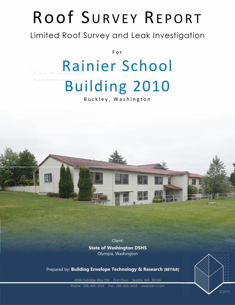
Roof S U R V E Y R E P O R T
Limited Roof Survey and Leak Investigation
F o r
Rainier School
Building 2010 B u c k l e y , W a s h i n g t o n
Client:
State of Washington DSHS Olympia, Washington
Prepared by: Building Envelope Technology & Research [BET&R]
4000 Delridge Way SW First Floor Seattle, WA 98106
Phone: 206-405-3455 Fax: 206-405-3458 www.bet-r.com
©2019

RAINIER SCHOOL: BUILDING 2010 ROOF SURVEY AND REPORT
DATE OF REPORT Friday, June 28, 2019
PROJECT: Rainier School – Building 2010 Limited Roof Survey and Report
TO Dean Heglund, DSHS Project Manager CC: Scott Ward, Rainier School
CLIENT State of Washington DSHS Pat Bockelman, Rainier School Sean Yates, Rainier School
TEL 360-902-8158 Nat Stiles, Rainier School
E-MAIL [email protected]
Darren Johnston, Harbor Engineers Jim Carlson, BET&R Stephen Elliott, BET&R Zephyr Delahunt, BET&R
FROM Scott Vlotho | BET&R Architect
SUBJECT
RAINIER SCHOOL – BUILDING 2010 LIMITED ROOF SURVEY PRELIMINARY OBSERVATIONS, FINDINGS, AND RECOMMENDATIONS
Greetings,
BET&R is pleased to provide the following Building 2010 Limited Roof Survey Preliminary Observations, Findings, and Recommendations Report, including a schematic rough order of magnitude (ROM) budget cost estimate for potential repairs. Dean Heglund, DSHS Project Manager, requested a proposal from BET&R to conduct the limited roof survey at select areas of the Building 2010 roofs that have a history of reported water intrusion. The primary focus of this roof survey is directed at the north slope of the gable roof area. Previous repairs have reportedly been conducted at this roof area to address water intrusion, resultant wood decay, and roof structural framing damage. The purpose of this Limited Roof Survey was to examine existing conditions, document findings, and provide preliminary recommendations for potential repairs or reroofing, along with a schematic ROM budget cost estimate. BET&R has assisted Washington Department of Social & Health Services (DSHS) with other Rainier School buildings on the Buckley, Washington campus, performing on-site exterior envelope surveys, providing survey and condition assessment reports, and preparing Construction Documents including reroofing and roof repair specifications and drawings for the subject projects, as well as administering construction of several roof replacements, repairs, and retrofit projects. We look forward to continuing our relationship with the State of Washington DSHS and Rainier School. Sincerely, Building Envelope Technology and Research (BET&R)

Rainier School, State of Washington DSHS Page 2 of 28
Building 2010 Limited Roof Survey Preliminary Survey and Report June 28, 2019
Copyright © 2019 Building Envelope Technology & Research
TABLE OF CONTENTS PAGE
A INTRODUCTION 2 - 3
B EXECUTIVE SUMMARY 4 - 10
Testing and Survey Overview
Summary of Findings at 2010 Building
Summary of Recommendations at 2010 Building
C 2010 BUILDING TESTING AND SURVEY 20 - 35
Survey and Observations
D CONCLUSION 36 - 56
Summary of Findings
Recommendations
E APPENDIX | EXHIBITS 57 – 63
Exhibit A | Harbor Consulting Engineer’s Site Visit Report 15 Pages
Exhibit B | Preliminary ROM Matrix 1 Page
Exhibit C | Other Campus Buildings Identified with water intrusion for
priority repairs 11 Pages

Rainier School, State of Washington DSHS Page 3 of 28
Building 2010 Limited Roof Survey Preliminary Survey and Report June 28, 2019
Copyright © 2019 Building Envelope Technology & Research
A. INTRODUCTION
At the request of Dean Heglund, Project
Manager for Washington State Department
of Social and Health Services (DSHS) at
Rainier School, Building Envelope Technology
& Research (BET&R) was engaged to perform
a preliminary visual and tactile survey of
select roof areas and related attic conditions
at the 2010 Building, located on the campus
of Rainier School. BET&R was also requested
to provide potential repair, retrofit, and roof
replacement options, along with preliminary
Rough Order of Magnitude (ROM) budget
cost estimates based on the preliminary
findings of our survey.
BET&R’s Survey of select roof areas at the 2010 Building was conducted on Friday, June 7, 2019, by
BET&R’s Architect Scott Vlotho, and Building Envelope Technologist, Zephyr Delahunt. Darren
Johnston, Structural Engineer, from Harbor Consulting Engineers (HCE), assisted with the survey and
provided preliminary analysis of the existing wood roof framing and structural system. Mr. Johnston’s
structural analysis and Site Visit Report is attached as an appendix to BET&R’s Roof Survey Report. The
intent of this preliminary survey was to provide an initial condition assessment of select roof areas and
was not intended to provide a complete analysis for the preparation of full design documents for any
roof retrofit or replacement options that may be considered by the State of Washington, DSHS, and
Rainier School officials.
On-going water intrusion at the 2010 Building stemming from the roof system and leaking into the attic
cavity has been reported at numerous areas within the attic space. Visual evidence of leak water
staining on the underlying roof structural framing members observed during our roof attic survey
indicated that water intrusion appears to be widespread throughout the subject roof attic area. Many
of the original buildings on campus have been constructed of cast-in-place concrete, forming the floors,
walls, and ceiling structures. An approximately 6-inch thick concrete slab exists at the Building 2010
ceiling level, providing the floor level for the attic. As a result of the thick concrete ceiling/attic floor,
water intrusion may occur for some time before leaks may be reported within the occupied interior
spaces of the buildings.
BET&R has been privileged to work on a number of buildings on the Rainier School campus, providing
us with valuable experience and technical information specifically related to the building envelope
systems of these historic buildings as well as the construction methods, roofing system materials, and
structural framing systems observed on these buildings. Our history on-site includes work on the
following buildings:

Rainier School, State of Washington DSHS Page 4 of 28
Building 2010 Limited Roof Survey Preliminary Survey and Report June 28, 2019
Copyright © 2019 Building Envelope Technology & Research
Auditorium Building: Reroofing Project of the steep-slope pan and cover clay roof tile areas
and low-slope reroofing with a new multiple-ply SBS modified-asphalt roofing membrane
system;
Oakley Hall: Roofing repairs and retrofit of the valleys and select mechanical curb and roof
penetrations at the existing clay tile roofing system;
Meyer Hall: Roofing repairs and retrofit of the valleys and select mechanical curb and roof
penetrations at the existing clay tile roofing system;
Hemlock-Spruce Hall: Select roofing repairs at select valleys and roof replacement of select
roof areas with new SBS-modified asphalt shingle roofing to tie into an existing asphalt shingle
roof areas;
P-43 Maintenance Building: Tear-off of an existing problematic exposed-fastener metal panel
roof system and replacement with a new SBS-modified asphalt shingle roofing system.
BRIEF HISTORY OF 2010 BUILDING AND BACKGROUND INFORMATION FOR RAINIER SCHOOL:
The Rainier School campus is located in Buckley,
Washington in a valley at the base of the foot
hills leading up to Mount Rainier. The primary
campus buildings were generally designed and
constructed from the late 1930’s through the
mid 1950’s. The geographic location of the
campus creates its own unique micro-climate
type weather conditions and challenges for the
building envelope systems of the buildings. The
weather is often more extreme than that
experienced at adjacent areas and
communities. Higher wind levels and velocities
are often experienced, and larger amounts of
precipitation, including both rain and snow fall,
can be heavier and more pronounced than
typical weather conditions for the region.
The subject of this roof survey, the 2010 Building, appears to have been designed in 1952 by the Seattle
architectural office of Naramore, Bain, Brady and Johanson (NBBJ). The first phase of the original
buildings constructed on-site were designed by noted Seattle architect, Graham and Painter Architects.
Historic campus maps of Rainier School appear to indicate that the 2010 Building was under
construction in 1953.
Like many of the original Rainier School campus buildings, the 2010 Building utilizes a thick cast-in-place
concrete structure for the primary walls and floor/ceiling components. With readily available timbers
and old-growth wood, the roof structures are framed with large-dimension, high-quality wood, milled
Rainier School, State of Washington DSHS Page 5 of 28
Building 2010 Limited Roof Survey Preliminary Survey and Report June 28, 2019
Copyright © 2019 Building Envelope Technology & Research
from the nearby forests. On top of the main structure, roof decking consists of 2x6 tongue-and-groove
“car decking” lumber. For the 2010 Building, the tongue-and-groove wood-roof decking was installed in
alignment running parallel to the slope of the roof, extending from the downslope eave, up to the ridge
of the roof areas, and supported by intermittent shaped 4x10 wood beams within the attic space. The
roofing systems consists of one layer of underlayment and mechanically-attached interlocking S-shaped
style red clay roofing tiles. The older original buildings at Rainier School incorporated more traditional
pan-and-cover clay tile roofing.
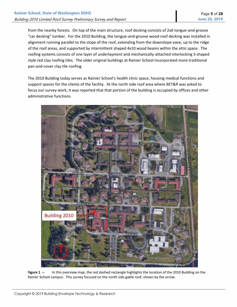
The 2010 Building today serves as Rainier School’s health clinic space, housing medical functions and
support spaces for the clients of the facility. At the north side roof area where BET&R was asked to
focus our survey work, it was reported that that portion of the building is occupied by offices and other
administrative functions.
Figure 1 -- In this overview map, the red dashed rectangle highlights the location of the 2010 Building on the Rainier School campus. This survey focused on the north side gable roof, shown by the arrow.
Rainier School, State of Washington DSHS Page 6 of 28
Building 2010 Limited Roof Survey Preliminary Survey and Report June 28, 2019
Copyright © 2019 Building Envelope Technology & Research
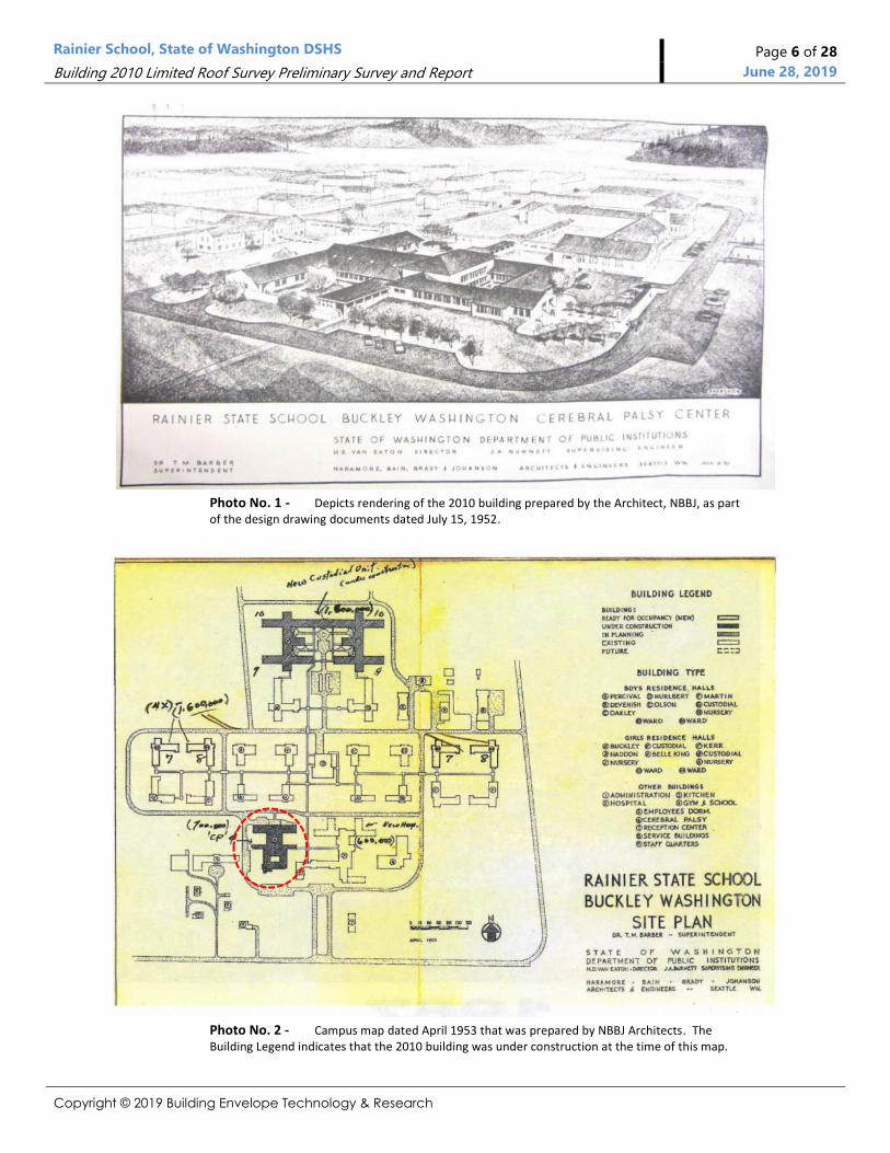
Photo No. 1 - Depicts rendering of the 2010 building prepared by the Architect, NBBJ, as part of the design drawing documents dated July 15, 1952.
Photo No. 2 - Campus map dated April 1953 that was prepared by NBBJ Architects. The Building Legend indicates that the 2010 building was under construction at the time of this map.

Rainier School, State of Washington DSHS Page 7 of 28
Building 2010 Limited Roof Survey Preliminary Survey and Report June 28, 2019
Copyright © 2019 Building Envelope Technology & Research
Photo No. 3 - Building 2010 Construction Photo
Photo depicts construction of the
2010 building. Note the main
Administration Building in the
background.
Photo No. 4 - Building 2010 Construction Photo
Aerial photograph of the Rainier
School site during construction of
Building 2010, identified with the
yellow circle. No date was
provided on the photo; however,
other documents appear to
indicate construction was
underway in 1953.
Photo No. 5 - Building 2010 1967 Aerial Campus View
Aerial photo of the Rainier School
campus as shown in 1967.
Building 2010 is circled near the
middle of the photo.
Rainier School, State of Washington DSHS Page 8 of 28
Building 2010 Limited Roof Survey Preliminary Survey and Report June 28, 2019
Copyright © 2019 Building Envelope Technology & Research
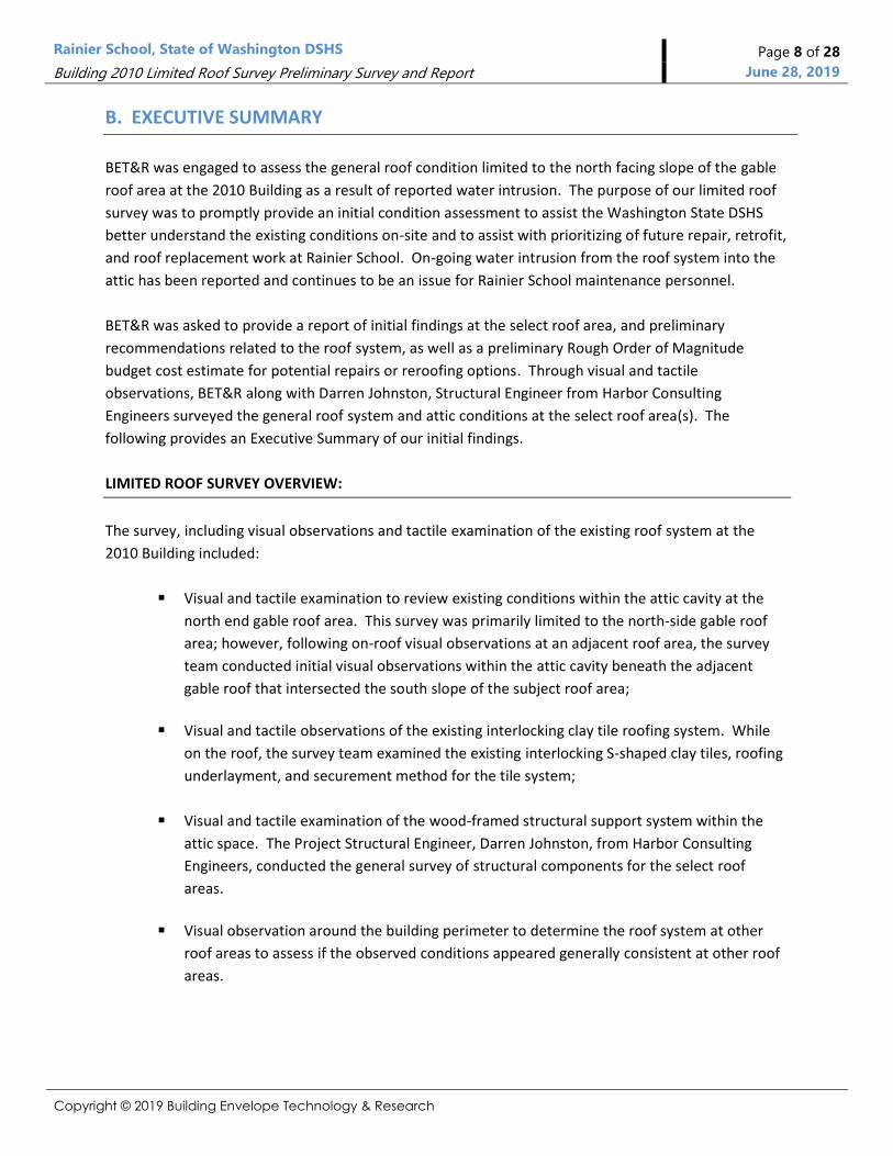
B. EXECUTIVE SUMMARY
BET&R was engaged to assess the general roof condition limited to the north facing slope of the gable
roof area at the 2010 Building as a result of reported water intrusion. The purpose of our limited roof
survey was to promptly provide an initial condition assessment to assist the Washington State DSHS
better understand the existing conditions on-site and to assist with prioritizing of future repair, retrofit,
and roof replacement work at Rainier School. On-going water intrusion from the roof system into the
attic has been reported and continues to be an issue for Rainier School maintenance personnel.
BET&R was asked to provide a report of initial findings at the select roof area, and preliminary
recommendations related to the roof system, as well as a preliminary Rough Order of Magnitude
budget cost estimate for potential repairs or reroofing options. Through visual and tactile
observations, BET&R along with Darren Johnston, Structural Engineer from Harbor Consulting
Engineers surveyed the general roof system and attic conditions at the select roof area(s). The
following provides an Executive Summary of our initial findings.
LIMITED ROOF SURVEY OVERVIEW:
The survey, including visual observations and tactile examination of the existing roof system at the
2010 Building included:
Visual and tactile examination to review existing conditions within the attic cavity at the
north end gable roof area. This survey was primarily limited to the north-side gable roof
area; however, following on-roof visual observations at an adjacent roof area, the survey
team conducted initial visual observations within the attic cavity beneath the adjacent
gable roof that intersected the south slope of the subject roof area;
Visual and tactile observations of the existing interlocking clay tile roofing system. While
on the roof, the survey team examined the existing interlocking S-shaped clay tiles, roofing
underlayment, and securement method for the tile system;
Visual and tactile examination of the wood-framed structural support system within the
attic space. The Project Structural Engineer, Darren Johnston, from Harbor Consulting
Engineers, conducted the general survey of structural components for the select roof
areas.
Visual observation around the building perimeter to determine the roof system at other
roof areas to assess if the observed conditions appeared generally consistent at other roof
areas.
Rainier School, State of Washington DSHS Page 9 of 28
Building 2010 Limited Roof Survey Preliminary Survey and Report June 28, 2019
Copyright © 2019 Building Envelope Technology & Research
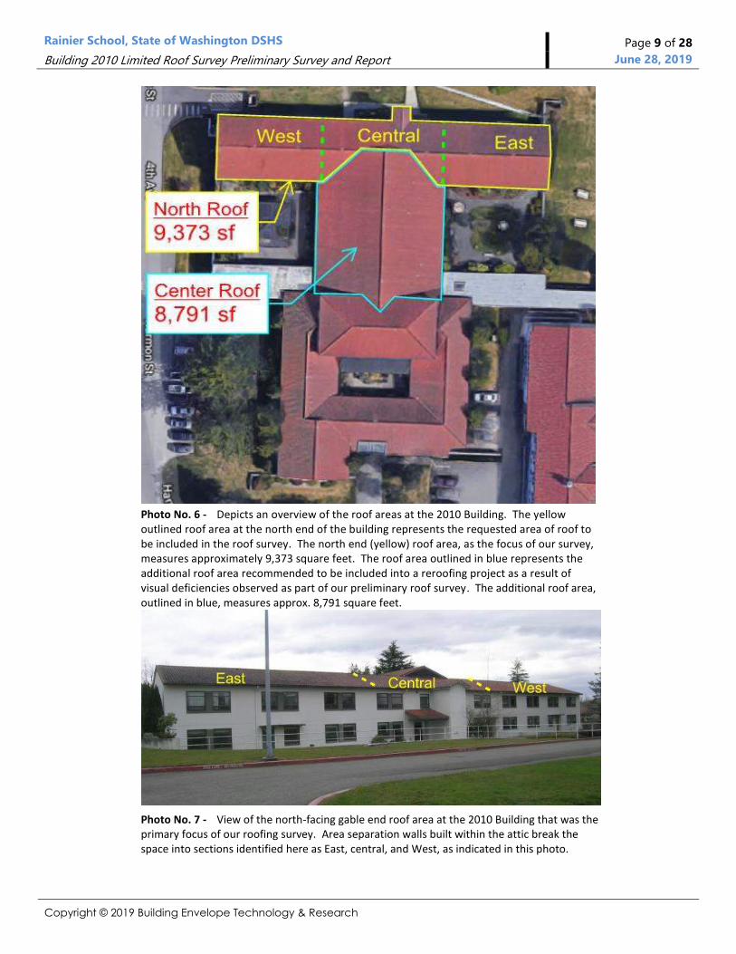
Photo No. 6 - Depicts an overview of the roof areas at the 2010 Building. The yellow outlined roof area at the north end of the building represents the requested area of roof to be included in the roof survey. The north end (yellow) roof area, as the focus of our survey, measures approximately 9,373 square feet. The roof area outlined in blue represents the additional roof area recommended to be included into a reroofing project as a result of visual deficiencies observed as part of our preliminary roof survey. The additional roof area, outlined in blue, measures approx. 8,791 square feet.
Photo No. 7 - View of the north-facing gable end roof area at the 2010 Building that was the primary focus of our roofing survey. Area separation walls built within the attic break the space into sections identified here as East, central, and West, as indicated in this photo.
Rainier School, State of Washington DSHS Page 10 of 28
Building 2010 Limited Roof Survey Preliminary Survey and Report June 28, 2019
Copyright © 2019 Building Envelope Technology & Research
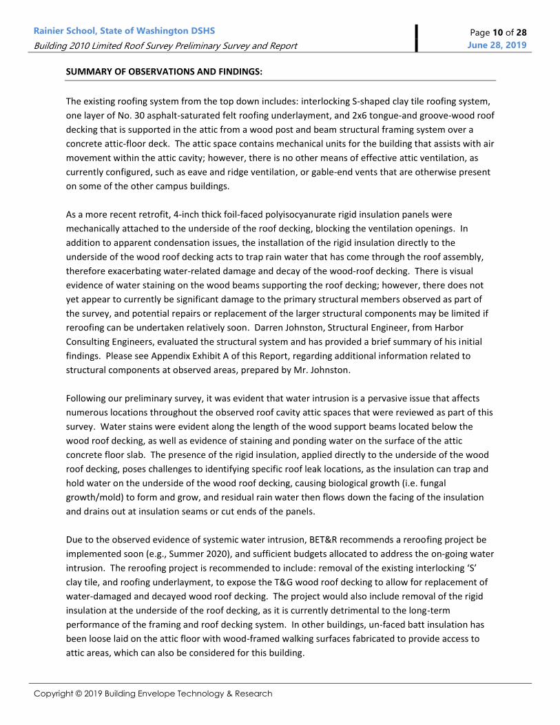
SUMMARY OF OBSERVATIONS AND FINDINGS:
The existing roofing system from the top down includes: interlocking S-shaped clay tile roofing system,
one layer of No. 30 asphalt-saturated felt roofing underlayment, and 2x6 tongue-and groove-wood roof
decking that is supported in the attic from a wood post and beam structural framing system over a
concrete attic-floor deck. The attic space contains mechanical units for the building that assists with air
movement within the attic cavity; however, there is no other means of effective attic ventilation, as
currently configured, such as eave and ridge ventilation, or gable-end vents that are otherwise present
on some of the other campus buildings.
As a more recent retrofit, 4-inch thick foil-faced polyisocyanurate rigid insulation panels were
mechanically attached to the underside of the roof decking, blocking the ventilation openings. In
addition to apparent condensation issues, the installation of the rigid insulation directly to the
underside of the wood roof decking acts to trap rain water that has come through the roof assembly,
therefore exacerbating water-related damage and decay of the wood-roof decking. There is visual
evidence of water staining on the wood beams supporting the roof decking; however, there does not
yet appear to currently be significant damage to the primary structural members observed as part of
the survey, and potential repairs or replacement of the larger structural components may be limited if
reroofing can be undertaken relatively soon. Darren Johnston, Structural Engineer, from Harbor
Consulting Engineers, evaluated the structural system and has provided a brief summary of his initial
findings. Please see Appendix Exhibit A of this Report, regarding additional information related to
structural components at observed areas, prepared by Mr. Johnston.
Following our preliminary survey, it was evident that water intrusion is a pervasive issue that affects
numerous locations throughout the observed roof cavity attic spaces that were reviewed as part of this
survey. Water stains were evident along the length of the wood support beams located below the
wood roof decking, as well as evidence of staining and ponding water on the surface of the attic
concrete floor slab. The presence of the rigid insulation, applied directly to the underside of the wood
roof decking, poses challenges to identifying specific roof leak locations, as the insulation can trap and
hold water on the underside of the wood roof decking, causing biological growth (i.e. fungal
growth/mold) to form and grow, and residual rain water then flows down the facing of the insulation
and drains out at insulation seams or cut ends of the panels.
Due to the observed evidence of systemic water intrusion, BET&R recommends a reroofing project be
implemented soon (e.g., Summer 2020), and sufficient budgets allocated to address the on-going water
intrusion. The reroofing project is recommended to include: removal of the existing interlocking ‘S’
clay tile, and roofing underlayment, to expose the T&G wood roof decking to allow for replacement of
water-damaged and decayed wood roof decking. The project would also include removal of the rigid
insulation at the underside of the roof decking, as it is currently detrimental to the long-term
performance of the framing and roof decking system. In other buildings, un-faced batt insulation has
been loose laid on the attic floor with wood-framed walking surfaces fabricated to provide access to
attic areas, which can also be considered for this building.
Rainier School, State of Washington DSHS Page 11 of 28
Building 2010 Limited Roof Survey Preliminary Survey and Report June 28, 2019
Copyright © 2019 Building Envelope Technology & Research
Following removal and replacement of the roof decking and related substrate components, we
recommend installation of a new roofing system consisting of 2-ply asphalt-based roofing
underlayment and new primary roof covering. Although we have reused and reinstalled the more
traditional pan-and-cover clay roofing tiles at other campus buildings, the existing mechanically-
attached interlocking S-profile clay tile roofing at the 2010 Building will be difficult to salvage for
reinstallation without breaking large numbers of them during removal. As such, we recommend
installation of new sheet metal panel roofing as a prudent roof system that will provide a long-term,
weather-tight roofing solution. The lighter metal panel roof system is also more appropriate for the
existing, relatively wide span, structural framing. While a reroofing project obviously entails all the
associated costs of reroofing, the exterior areas of the building itself appears to be in great condition,
and the primary roof structural members observed during this roof survey appear to still be in good
serviceable condition. A correctly designed roof replacement project, to be conducted as soon as
possible, will protect the structure and building into the future and reduce much larger costs that will
be necessary if reroofing is postponed. If water intrusion continues to be allowed, it will result in
further damage, fungal growth, and decay to persist and expand. As the primary clinic for medical
services on the Rainier School campus, the 2010 Building is a critical facility that should be prioritized
for proper reroofing, to be correctly designed in order to maintain the Building function and
operability.
During our survey we also observed an area of deflected/sagging roof-related components at the
center roof area adjacent the valley on the east side of the roof areas. Several large electrical conduits
are located below the area and attached to the underside of the roof decking. This area is an area of
critical concern and is recommended to be repaired immediately.
The layout of the 2010 Building allows for reroofing to be planned out, prioritized, and conducted in
phases as budgets become available. For an initial phase it is recommended that the north-side gable
roof, along with the adjacent north-south oriented roof area, extending perpendicular to the subject
roof area, both be included in the first phase of reroofing. Please Note: The two valleys where the roof
areas intersect appear to be particular systemic zones of water intrusion and are in poor condition
including extensive wood decay. Select areas of the adjacent north-south extending roof area also
showed visual evidence of deflection/sagging of the roof system and existing affected wood roof
decking, and is recommended to be further evaluated and included in a reroofing project. It appears
there are water-damaged and decayed roof decking that needs to be replaced in order to maintain the
integrity of the building. Although the observed deflection/sagging this subject roof area described
was outside of your requested primary roof survey area, the area in question requires further in-depth
evaluation and is recommended to be invasively investigated, evaluated, and repaired soon as a
potential emergency repair scenario. A number of large electrical conduits were attached to the
underside of the roof decking at this general location, and further degradation of the roof system may
lead to partial roof collapse and potential disruption to critical services and functions of the building.

Rainier School, State of Washington DSHS Page 12 of 28
Building 2010 Limited Roof Survey Preliminary Survey and Report June 28, 2019
Copyright © 2019 Building Envelope Technology & Research
Photo No. 8 - View of the north-facing gable roof area at the 2010 Building that was the primary focus of our roofing survey.
Photo No. 9 - View of the north-facing gable end roof area at the 2010 Building showing the west end of the roof area. It was reported that a portion of the roof area, shown by the red hatched line identified area, was previously repaired to address water-intrusions and water-damaged T&G roof decking.

Rainier School, State of Washington DSHS Page 13 of 28
Building 2010 Limited Roof Survey Preliminary Survey and Report June 28, 2019
Copyright © 2019 Building Envelope Technology & Research
SUMMARY OF RECOMMENDATIONS AT 2010 BUILDING:
Existing Clay Tile Roofing System at North End Roof Area(s)
Due to systemic water intrusion observed throughout numerous areas of the north end
gable roof as well as the adjacent intersecting roof areas, BET&R recommends removal and
replacement of the existing roofing system. The 2010 Building, which serves as the campus
health clinic and also houses clients that require acute care, is a critical facility and any
disruption of services due to issues related to on-going water intrusion would be
detrimental to the operation and mission of Rainier School. Given the systemic issues, and
difficulty to pin point specific origins of the water leaks partly due to the existing rigid
insulation fixed directly below the wood roof decking, it is our opinion that attempting to
perform targeted repairs, as we have done on some of the buildings on campus, is not
feasible as an efficient nor cost effective repair and thus not a prudent use of budget
resources. As part of the retrofit and reroofing project, the rigid insulation should be
removed from the underside of the decking, abated, and new un-faced-batt insulation
placed at the attic floor level, as has been done on other campus buildings. A wood-framed
walkway system can be constructed to provide access to attic areas of the building.
Ventilation of the attic spaces should also be addressed during reroofing design, so it can
be properly provided for with any reroofing work.
The existing interlocking S-profile clay roof tiles are more difficult to carefully remove,
stack, and store for reinstallation, as has been done on other campus buildings with the
more traditional pan-and-cover clay roofing tiles, and as such it may be prudent to consider
installation of a sheet metal panel roofing system, such as a standing-seam roof system
installed over new plywood roof sheathing and roofing underlayment. If it is the State of
Washington’s desire to maintain the look of the clay tile, sheet metal panel manufacturers
also fabricate metal panel systems to more closely replicate the look of clay tile, which may
be an option to consider.
Select structural repair and retrofit may also be needed within the attic cavities, and a
lighter metal panel roof system that does not weigh as much as the existing heavy clay
roofing tiles may assist to limit the level of retrofit needed, based upon the Project
Structural Engineer’s recommendations.
A reroofing project can be phased at the 2010 Building, and we recommend starting at the
north end gable roof area, extending in the east-west direction, as well as the transverse
center roof area extending north-south. The two recommended roof areas form a T-shape
and could be transitioned at the valley areas of adjacent roof areas for additional future
phases of work. This work can be achieved while the building is occupied, and completed
so as not to interfere with the function and operation of the facility. We have worked on
other Rainier School campus projects to ensure that the work is performed in a safe
Rainier School, State of Washington DSHS Page 14 of 28
Building 2010 Limited Roof Survey Preliminary Survey and Report June 28, 2019
Copyright © 2019 Building Envelope Technology & Research
manner that protects the safety and welfare of the clients, staff, and roofing personnel
while maintaining the integrity of the existing building, with the goal of delivering a high-
performance, water-tight building that can serve the campus for many years to come.
TABLE 1 | RAINIER SCHOOL: 2010 BUILDING
Condition Recommendation Location Test Performed ROM
A. North Roof Area Systemic water intrusion
observed throughout attic spaces,
Existing rigid insulation is problematic and traps leak water against wood decking,
Numerous broken tiles throughout field of roof area.
Remove interlocking Spanish clay tile roofing
Retrofit and repair roof structure members, as needed;
Install new plywood sheathing, underlayment and roofing system.
North end wing gable roof area as shown in roof plan below (Requested roof area of primary focus)
Tactile and visual testing
See attached ROM Matrix
B. Center Roof Area Systemic water intrusion
observed throughout attic spaces,
Existing rigid insulation is problematic and traps leak water against wood decking,
Numerous broken tiles throughout field of roof area.
Remove interlocking Spanish clay tile roofing Retrofit and repair roof structure members, as needed;
Install new plywood sheathing, underlayment and roofing system
Center wing gable roof area as shown in roof plan below (Included in survey due to observed deficiencies)
Tactile and visual testing
See attached ROM Matrix
C. 2010 LIMITED ROOF AREA AND ATTIC SURVEY
The following section provides a more detailed description of the survey work performed and
assessment of the conditions observed. This Report also includes information related to the initial
assessment of the roofing and attic structural components surveyed by Darren Johnston, from Harbor
Consulting Engineer’s. The end of this Report also includes a preliminary Rough Order of Magnitude
(ROM) estimate for potential reroofing options for further discussion and consideration.
On Friday June 7, 2019, BET&R, along with Harbor Consulting Engineer’s performed a roofing survey at
the north end roof area. The survey team performed visual and tactile observations within the attic
cavity as well as at the roof level. While on the roof to survey the subject north end roof area, visual
signs of roof sagging at the adjacent center roof area extending towards the south prompted the Team
to note the observations and conduct additional interior visual survey within the attic near the affected
area(s). No destructive test openings were conducted as part of this survey. The preliminary nature of
this initial survey and assessment was not conducted to serve as a design survey and additional
investigation will be needed as any potential future project proceeds. The following is a summary of the
observations and examination performed by BET&R at the select roof and attic areas:

Rainier School, State of Washington DSHS Page 15 of 28
Building 2010 Limited Roof Survey Preliminary Survey and Report June 28, 2019
Copyright © 2019 Building Envelope Technology & Research
Photo No. 10 - Interlocking Clay Roof Tile Profile
Photo depicting the profile of the
existing interlocking S-shaped profile
clay tile roofing system installed at the
2010 Building.
Photo No. 11 - Observations at Typical Valley
The copper valley flashing liner is in
poor condition at this time. The center
rib has been creased and pressed down
flat in several locations and should be
replaced with a new sheet metal valley
as part of a reroofing project. Several
cracked, and/or displaced roofing tiles
were also identified along the valleys
and field of the roof areas.
Photo No. 12 - Example of Cracked and Broken Roof Tiles Observed in Field of the Roof Areas
Close-up of typical cracked clay roofing
tiles observed at the subject roof areas.
The photo shows the exposed 1-ply
underlayment beneath the tiles leading
to the potential of water intrusion. UV
exposure accelerates the aging of the
underlayment, causing deterioration
and potential failure of the
underlayment.
Rainier School, State of Washington DSHS Page 16 of 28
Building 2010 Limited Roof Survey Preliminary Survey and Report June 28, 2019
Copyright © 2019 Building Envelope Technology & Research
Photo No. 13 - Building 2010 Attic Photo in West Roof Area
Area separation walls within the attic
break the overall space into three
separate attic sections. This photo
depicts existing attic conditions within
the west side of the subject roof area
looking west. Foil-faced
polyisocyanurate insulation is
mechanically-attached to the underside
of the tongue-and-groove wood roof
decking.
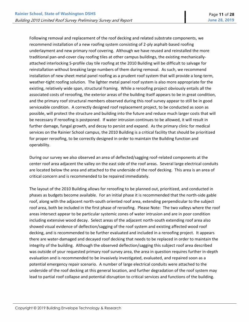
Photo No. 14 - Building 2010 Attic Photo in Center Roof Area
Depicts conditions at the west section
of the attic near the area separation
wall within the center attic area. The
arrows show evidence of water staining
on the wood beams. The insulation
inhibits identification of leak sources
and acts to trap rain water against the
wood decking, causing further damage
and decay to wood framing
components.
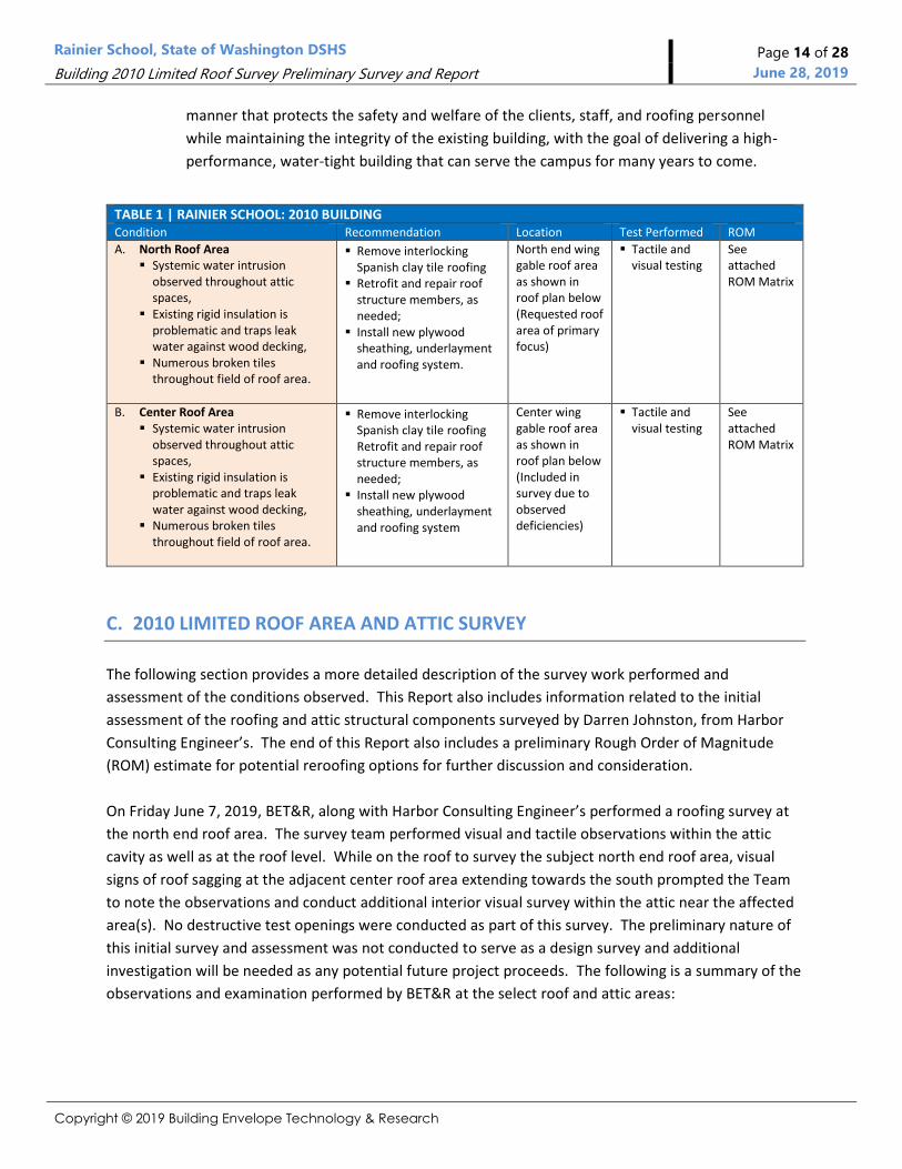
Photo No. 15 - Building 2010 Attic Photo in West Roof Area
The 2x6 T&G wood decking runs
parallel with the roof slope and is
supported along the ridge line, two
intermediate beams that extend the
length of the attic and along the
downslope eave edge. The two arrows
identify the two intermediate beams
that have been framed at approximate
10’-3” spacing intervals. The general
test opening area is also shown.

Rainier School, State of Washington DSHS Page 17 of 28
Building 2010 Limited Roof Survey Preliminary Survey and Report June 28, 2019
Copyright © 2019 Building Envelope Technology & Research
Photo No. 16 - Building 2010 North End Roof Area
As part of our roof survey, we removed
select areas of interior insulation under
the roof deck to observe conditions at
the wood decking. The arrow depicts the
general location of the testing and
survey area at the west side area of the
attic. The arrow points to a ridge vent
that is shown in photos below.
Photo No. 17 - North End Roof Area and Ridge Vent at Test Area
Closer photo of ridge vent location and
general area where observations of the
wood decking were documented from
within the attic space.
Photo No. 18 - Attic view at Ridge Vent Location
The arrow depicts the cut-out of the
wood decking at the location of the small
ridge vent that was blocked by the
insulation. The wood at the vent appears
to be in good, dry condition. Evidence of
water intrusion and staining was
observed downslope. The following
photos depict those conditions.
Rainier School, State of Washington DSHS Page 18 of 28
Building 2010 Limited Roof Survey Preliminary Survey and Report June 28, 2019
Copyright © 2019 Building Envelope Technology & Research
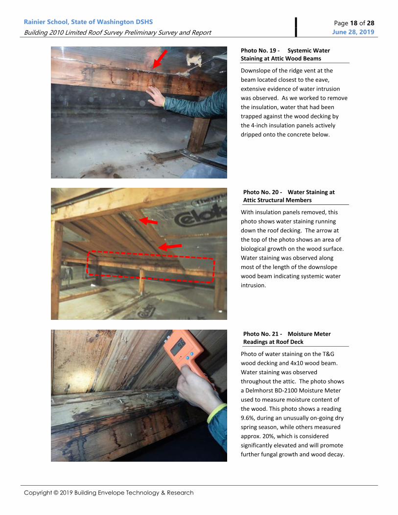
Photo No. 19 - Systemic Water Staining at Attic Wood Beams
Downslope of the ridge vent at the
beam located closest to the eave,
extensive evidence of water intrusion
was observed. As we worked to remove
the insulation, water that had been
trapped against the wood decking by
the 4-inch insulation panels actively
dripped onto the concrete below.
Photo No. 20 - Water Staining at Attic Structural Members
With insulation panels removed, this
photo shows water staining running
down the roof decking. The arrow at
the top of the photo shows an area of
biological growth on the wood surface.
Water staining was observed along
most of the length of the downslope
wood beam indicating systemic water
intrusion.
Photo No. 21 - Moisture Meter Readings at Roof Deck
Photo of water staining on the T&G
wood decking and 4x10 wood beam.
Water staining was observed
throughout the attic. The photo shows
a Delmhorst BD-2100 Moisture Meter
used to measure moisture content of
the wood. This photo shows a reading
9.6%, during an unusually on-going dry
spring season, while others measured
approx. 20%, which is considered
significantly elevated and will promote
further fungal growth and wood decay.

Rainier School, State of Washington DSHS Page 19 of 28
Building 2010 Limited Roof Survey Preliminary Survey and Report June 28, 2019
Copyright © 2019 Building Envelope Technology & Research
Photo No. 22 - Water Staining and Biological Growth Trapped by Insulation
As other insulation panels upslope
where removed, the water
staining continued. The white
colored substance appeared to be
biological growth (i.e. mold).
Water staining on the top-surface
of the insulation against the wood
decking, showed signs of staining
on the foil-facer.
Photo No. 23 - Water Staining and Biological Growth on Wood Structure
Closer photo of water staining and
biological growth which had been in
contact with the intermediate beam
closest to the ridge.
Photo No. 24 - Attic Conditions Downslope from Ridge Vent
The water staining shown in previous
photos continued to extend upslope and
appeared to originate near the point of
the arrow. For reference, the cutout for
the ridge vent is shown in the upper left
corner.

Rainier School, State of Washington DSHS Page 20 of 28
Building 2010 Limited Roof Survey Preliminary Survey and Report June 28, 2019
Copyright © 2019 Building Envelope Technology & Research
Photo No. 25 - North-facing gable end roof looking west
View of the north-facing side of the
gable roof looking west. The arrow
shows the approx. location of the test
area shown in previous photos.
Photo No. 26 - North-facing gable end roof near test area
Closer photo showing location of the
ridge vent location and BET&R roofing
technician conducting roof level
observations.
Photo No. 27 - Example gable vent at north end roof area
At the ridge vent, the openings were
protected with a sheet metal flashing
hood. As a general note, the small
ridge vents do not appear to be
effective for providing adequate roof
ventilation, particularly as the rigid
insulation fully blocks the vent opening.
It also appeared that no downslope
eave intake vents were provided.

Rainier School, State of Washington DSHS Page 21 of 28
Building 2010 Limited Roof Survey Preliminary Survey and Report June 28, 2019
Copyright © 2019 Building Envelope Technology & Research
Photo No. 28 - Attic View within West Section of Roof
Photo looking east within the west attic
area. The photo shows several areas of
water staining along the supporting
posts and beams.
Photo No. 29 - Attic View within Central Section of Roof
Photo near the stair access of the central
area in the attic. Again, several areas of
water staining on beams were observed.
Photo No. 30 - Attic View within East Section of Roof
Depicts evidence of water staining near
the east gable end of the east attic area.
Please refer to Site Visit Report prepared
by Harbor Consulting Engineer’s
regarding structural components.
Rainier School, State of Washington DSHS Page 22 of 28
Building 2010 Limited Roof Survey Preliminary Survey and Report June 28, 2019
Copyright © 2019 Building Envelope Technology & Research
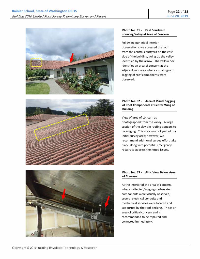
Photo No. 31 - East Courtyard showing Valley at Area of Concern
Following our initial interior
observations, we accessed the roof
from the central courtyard on the east
side of the building, going up the valley
identified by the arrow. The yellow box
identifies an area of concern at the
adjacent roof area where visual signs of
sagging of roof components were
observed.
Photo No. 32 - Area of Visual Sagging of Roof Components at Center Wing of Building
View of area of concern as
photographed from the valley. A large
section of the clay tile roofing appears to
be sagging. This area was not part of our
initial survey area; however, we
recommend additional survey effort take
place along with potential emergency
repairs to address the noted issues.
Photo No. 33 - Attic View Below Area of Concern
At the interior of the area of concern,
where deflected/sagging roof-related
components were visually observed,
several electrical conduits and
mechanical services were located and
supported by the roof decking. This is an
area of critical concern and is
recommended to be repaired and
corrected immediately.

Rainier School, State of Washington DSHS Page 23 of 28
Building 2010 Limited Roof Survey Preliminary Survey and Report June 28, 2019
Copyright © 2019 Building Envelope Technology & Research
Photo No. 34 - Valley at East Side of Roof Survey Area
Water intrusion was also identified to
be problematic at the two valley
locations observed during the survey.
The valley shown in this photo is
located in the courtyard space between
the north and center roof sections on
the eastern side of the building. The
valley flashing was in poor condition
and evidence of water intrusion within
the attic was prevalent.
Photo No. 35 - Evidence of Water-Staining at Valleys
Systemic observations of water
intrusion were noted along both of the
valley’s that intersect the north wing
roof area. Select wood framing
members may also need to be replaced
due to water-damage and decay at the
valley locations. Evidence of staining on
the concrete floor was also evident.
Photo No. 36 - Evidence of Water-Staining at Valleys
The west side valley also showed
evidence of water intrusion. On other
campus buildings, the existing valleys
have been problematic with on-going
water intrusion issues. Redesign and
retrofit of the valleys and flashing
systems is recommended.
Rainier School, State of Washington DSHS Page 24 of 28
Building 2010 Limited Roof Survey Preliminary Survey and Report June 28, 2019
Copyright © 2019 Building Envelope Technology & Research
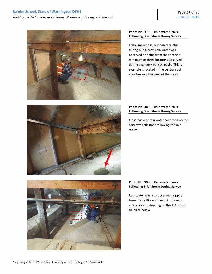
Photo No. 37 - Rain-water leaks Following Brief Storm During Survey
Following a brief, but heavy rainfall
during our survey, rain water was
observed dripping from the roof at a
minimum of three locations observed
during a cursory walk through. This is
example is located in the central roof
area towards the west of the stairs.
Photo No. 38 - Rain-water leaks Following Brief Storm During Survey
Closer view of rain water collecting on the
concrete attic floor following the rain
storm.
Photo No. 39 - Rain-water leaks Following Brief Storm During Survey
Rain water was also observed dripping
from the 4x10 wood beam in the east
attic area and dripping on the 2x4 wood
sill plate below.

Rainier School, State of Washington DSHS Page 25 of 28
Building 2010 Limited Roof Survey Preliminary Survey and Report June 28, 2019
Copyright © 2019 Building Envelope Technology & Research
D. CONCLUSION Survey Summary and General Findings:
During on-site roof survey work by BET&R and HCE, we discovered numerous deficiencies, and active
water intrusion was observed within the roof level and roof attic space of the 2010 Building during a
brief rain event. Rainier School personnel has reported that rain water leaks into the attic space of the
north end roof area at several locations, requiring buckets to contain and then empty out on a regular
basis. (Note: We observed water dripping out of the roof system and onto the attic floor following a
brief rain storm.)
Based upon our roof survey observations, systemic water intrusion appears to be widespread
throughout the roof attic areas requested for BET&R to survey. Signs of water intrusion were observed
in the field of the roof as well as at critical transitions and flashing intersections, and adjacent roof
areas’ valleys. While much of the visual evidence presented as surface staining on the wood framing
(e.g., wood roof beams) and other structural members, it is suspected that several areas of the tongue-
and-groove wood decking are very decayed, and will need to be replaced. Select areas of deteriorated
wood sill plates will also require replacement, based upon evaluation by the structural engineer we
engaged in the roof survey. We believe it is imperative to conduct repairs and reroofing as soon as
possible and prior to additional significant damage and degradation of wood structural members, as
the costs of future repairs and replacement will only multiply as damaged areas continue to expand
and further deteriorate.
As requested by DSHS based upon reports of on-going water intrusion from Rainier School personnel,
BET&R focused the limited roofing survey approved for the north end roof area of the 2010 Building.
While that was our primary focus, other areas of concern were briefly reviewed as part of a general
building walk-around and on-roof observations, and select areas have been identified in this Report for
further investigation followed by recommended repairs and retrofit.
As many of the central Rainier School campus buildings were constructed from the late 1930’s through
the mid 1950’s, the buildings have reached an age where more intense roof repair and retrofit (e.g.,
reroofing) projects are prudent and needed to extend the service life of the buildings. The quality of
original construction and level of craftsmanship and materials was extremely high, resulting in
structures that were built to last. With proper repair and retrofit now, the core campus buildings can
provide many more years of service life. We are also aware of several other campus buildings, with
long-active roofing-related water intrusion issues, and it is our opinion that retrofit and reroofing
projects can cost-effectively and efficiently be conducted to continue the storied history of the core
campus buildings and important functions that they serve.
Rainier School, State of Washington DSHS Page 26 of 28
Building 2010 Limited Roof Survey Preliminary Survey and Report June 28, 2019
Copyright © 2019 Building Envelope Technology & Research
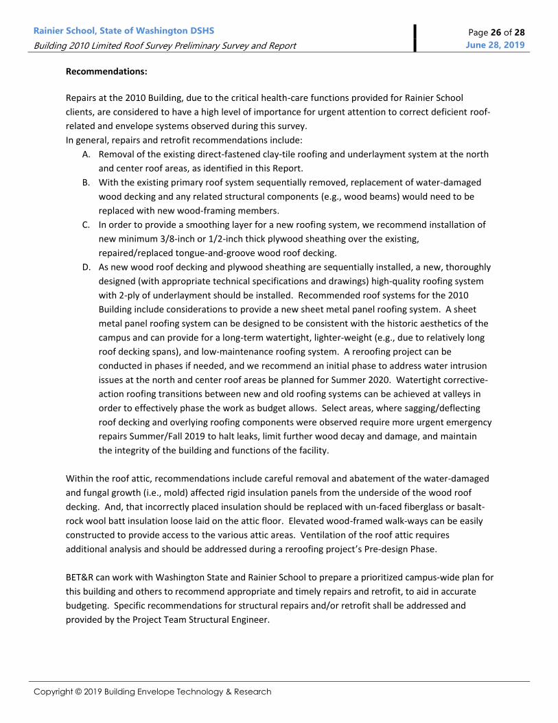
Recommendations:
Repairs at the 2010 Building, due to the critical health-care functions provided for Rainier School
clients, are considered to have a high level of importance for urgent attention to correct deficient roof-
related and envelope systems observed during this survey.
In general, repairs and retrofit recommendations include:
A. Removal of the existing direct-fastened clay-tile roofing and underlayment system at the north
and center roof areas, as identified in this Report.
B. With the existing primary roof system sequentially removed, replacement of water-damaged
wood decking and any related structural components (e.g., wood beams) would need to be
replaced with new wood-framing members.
C. In order to provide a smoothing layer for a new roofing system, we recommend installation of
new minimum 3/8-inch or 1/2-inch thick plywood sheathing over the existing,
repaired/replaced tongue-and-groove wood roof decking.
D. As new wood roof decking and plywood sheathing are sequentially installed, a new, thoroughly
designed (with appropriate technical specifications and drawings) high-quality roofing system
with 2-ply of underlayment should be installed. Recommended roof systems for the 2010
Building include considerations to provide a new sheet metal panel roofing system. A sheet
metal panel roofing system can be designed to be consistent with the historic aesthetics of the
campus and can provide for a long-term watertight, lighter-weight (e.g., due to relatively long
roof decking spans), and low-maintenance roofing system. A reroofing project can be
conducted in phases if needed, and we recommend an initial phase to address water intrusion
issues at the north and center roof areas be planned for Summer 2020. Watertight corrective-
action roofing transitions between new and old roofing systems can be achieved at valleys in
order to effectively phase the work as budget allows. Select areas, where sagging/deflecting
roof decking and overlying roofing components were observed require more urgent emergency
repairs Summer/Fall 2019 to halt leaks, limit further wood decay and damage, and maintain
the integrity of the building and functions of the facility.
Within the roof attic, recommendations include careful removal and abatement of the water-damaged
and fungal growth (i.e., mold) affected rigid insulation panels from the underside of the wood roof
decking. And, that incorrectly placed insulation should be replaced with un-faced fiberglass or basalt-
rock wool batt insulation loose laid on the attic floor. Elevated wood-framed walk-ways can be easily
constructed to provide access to the various attic areas. Ventilation of the roof attic requires
additional analysis and should be addressed during a reroofing project’s Pre-design Phase.
BET&R can work with Washington State and Rainier School to prepare a prioritized campus-wide plan for
this building and others to recommend appropriate and timely repairs and retrofit, to aid in accurate
budgeting. Specific recommendations for structural repairs and/or retrofit shall be addressed and
provided by the Project Team Structural Engineer.
Rainier School, State of Washington DSHS Page 27 of 28
Building 2010 Limited Roof Survey Preliminary Survey and Report June 28, 2019
Copyright © 2019 Building Envelope Technology & Research
REGARDING THIS REPORT:
On Site Survey, Report with Conclusions, and Recommendations:
This report, including initial conclusions and recommendations, is based upon observations of the
visible and apparent condition of the building, and the primary exterior components viewed and
examined on the date of this preliminary survey. Although care has been taken in the performance of
the survey, Building Envelope Technology & Research, Inc. (BET&R) makes no representations
regarding latent or concealed defects that may exist, and no warranty or guarantee is expressed or
implied.
This report is made in the best exercise of our technical ability, industry exposure, the time allotted,
and professional judgment. Conclusions in this summary report are based on estimates of the age and
normal service life of the various materials, components, and/or systems surveyed. Predictions of life
expectancy and the balance of useful service life are generally based on industry and regional
experienced comparisons. It is essential to understand that future weather (e.g., rain, snow and ice
accumulation, etc.) and compounding conditions (e.g., additional leakage, seismic event, etc.) can alter
the useful life of any material, item or building component. The weather exposure, (e.g., wetting and
drying, freeze-thaw cycling, etc.), use and misuse, irregularity of servicing, faulty manufacture and/or
construction, unfavorable conditions and installation, natural disasters (e.g., high-wind events,
earthquakes, etc.), and unforeseen circumstances make it impossible to state precisely, to the day,
when each item will require replacement.
Moisture Intrusion, Mold Growth, and Human Exposure to Mold
Persistent moisture intrusion, repetitive wetting, and/or the resulting elevated moisture content and
relative humidity in some situations can lead to the proliferation of biological and/or fungal growth
(e.g., mold) and other potentially hazardous contaminants and/or can spread fungus into interior
spaces, which can lead to allergic reactions in susceptible individuals and already compromised
persons, as well as other potential problems (hypersensitivity, etc.).
Limitations
This preliminary initial summary report is prepared for the exclusive use of the named Client and may
not be relied upon or used by any other party. In preparing this report for the named Client, the
authors assume no duty to lenders or other parties, none of whom are authorized to rely on its
contents.
Photographs were taken with the intent to document conditions and to help the Client understand the
actual conditions on-site. The photographs included in this summary report, were also taken to show
example areas, related conditions and situations; they are not inclusive of every situation, but of
general/typical conditions, and certain specific conditions.
This report provides an assessment/evaluation of the observed on-site conditions. It cannot be used as
specifications or written instructions for bidding, conducting repair or construction work. However, if

Rainier School, State of Washington DSHS Page 28 of 28
Building 2010 Limited Roof Survey Preliminary Survey and Report June 28, 2019
Copyright © 2019 Building Envelope Technology & Research
authorized by the Client, BET&R would be pleased to utilize this report to efficiently assemble a written
scope of work, or technical specifications and detail drawings from which to solicit bids and conduct
the necessary repairs and/or reroofing by quality-oriented contractors for the much-needed roof repair
and related work.
We trust the information is of assistance. Should you have any questions, comments or concerns
regarding the above initial Roof Survey, or if we may be of additional assistance, please do not hesitate to
contact me.
Respectfully,
Scott Vlotho, AIA
BET&R Architect | Building Envelope Technologist
BUILDING ENVELOPE TECHNOLOGY AND RESEARCH

Harbor Consulting Engineers, Inc.
3316 Fuhrman Avenue East Suite 250 ▪ Seattle, WA 98102 ▪ Telephone 206.709.2397 ▪ Facsimile 206.709.2398
SITE VISIT REPORT
TO: Mr. Scott Vlotho, A.I.A. 25 June 2019 Building Envelope Technology and Research RE: Rainier School Building 2010 Roof Framing Condition Assessment Report of Findings and
Recommendations for Repair and Rehabilitation 2120 Ryan Road Buckley, Washington
Dear Mr. Vlotho:
INTRODUCTION AND BACKGROUND Harbor Consulting Engineers, Inc. (Harbor) attended a one day on-site condition assessment of the timber roof framing of Building 2010 on the Rainier School Campus on 7 June 2019. In attendance during the site visit were Building Envelope Technology and Research (B.E.T. & R.) personnel Mr. Scott Vlotho, A.I.A. and Mr. Zephyr Delahunt. Harbor’s senior structural engineer Darren S. Johnston, P.E., S.E. performed the structural condition assessment. The building reviewed was a two story concrete framed early 1950’s era structure situated west of the main campus entry and administration offices. Record drawings for the building were not available at the time of our site visit and it is our understanding that record drawings cannot be located. Rainier School facility manager Mr. Scott Ward reported long term roof leakage in the attic of Building 2010. The focus of the structural assessment by Harbor is to determine the general structural condition of the timber roof framing and its serviceability to support superimposed roof dead and live loads. The building has complex and multi-level roof construction. The northern section of the building with an east-west dimension of approximately 224 feet and a north-south dimension of approximately 42 feet was reviewed in detail from the attic space. The attic of Building 2010 is accessible by an interior stairway. The attic space is partitioned into three areas separated by fire resistive barrier walls with an integral man door. The ceiling of the building was framed using reinforced concrete with structural slabs with upturned concrete beams loading concrete columns and bearing walls. The exterior walls of the building are constructed using exposed structural concrete and the second floor of the building appears to be a concrete structural slab. The lower floor of the structure is suspected to be a concrete slab on grade. Foundations appear to be conventional reinforced concrete strip footings and spread footings. The roof of the building is covered with manufactured thin Spanish-style roof tiles over roofing substrate. The roof framing over this portion of the building consists of 2X6 tongue and groove wood decking loading plumb 4X10 beams with shaped tops to support the decking slope. The shaped beam lines are placed at 1/6 points of the building short dimension with the central beam serving as ridge beam.
1 of 18

Harbor Consulting Engineers, Inc.
3316 Fuhrman Avenue East Suite 250 ▪ Seattle, WA 98102 ▪ Telephone 206.709.2397 ▪ Facsimile 206.709.2398
Timber beams are supported by 4X4 and 4X6 posts. Evidence of added post supports was noted in each of the three attic spaces. The central attic served by the access stairway houses a large air handler with ducting extending into the adjacent attic spaces. At some point following original construction the soffit of the roof decking was covered with foil-faced insulation panels anchored with annular shank nails with plate washers. The majority of the insulation panels were in place. Select locations had insulation panels removed during the site visit to view the underlying roof decking.
SITE VISIT OBSERVATIONS The attic was accessed and reviewed with personnel from B.E.T. & R. Selected locations in the northern attic section had rigid insulation panels removed to view the underlying roof decking condition. Harbor prepared field sketches of the three attic chambers showing the roof support beams, posts, upturned concrete beams, and dimensions. The three attic chambers were visually reviewed and digital photographs were taken to record conditions found. Harbor used a probe tool to evaluate timber framing exhibiting signs of deterioration. The roof was also accessed and briefly surveyed. Many roof tiles were loose and broken. The roofing assessment will be addressed by B.E.T. & R. in their written report. The following observations were made with respect to the timber roof framing of the northern section of Building 2010 based on visual and tactile methods of evaluation.
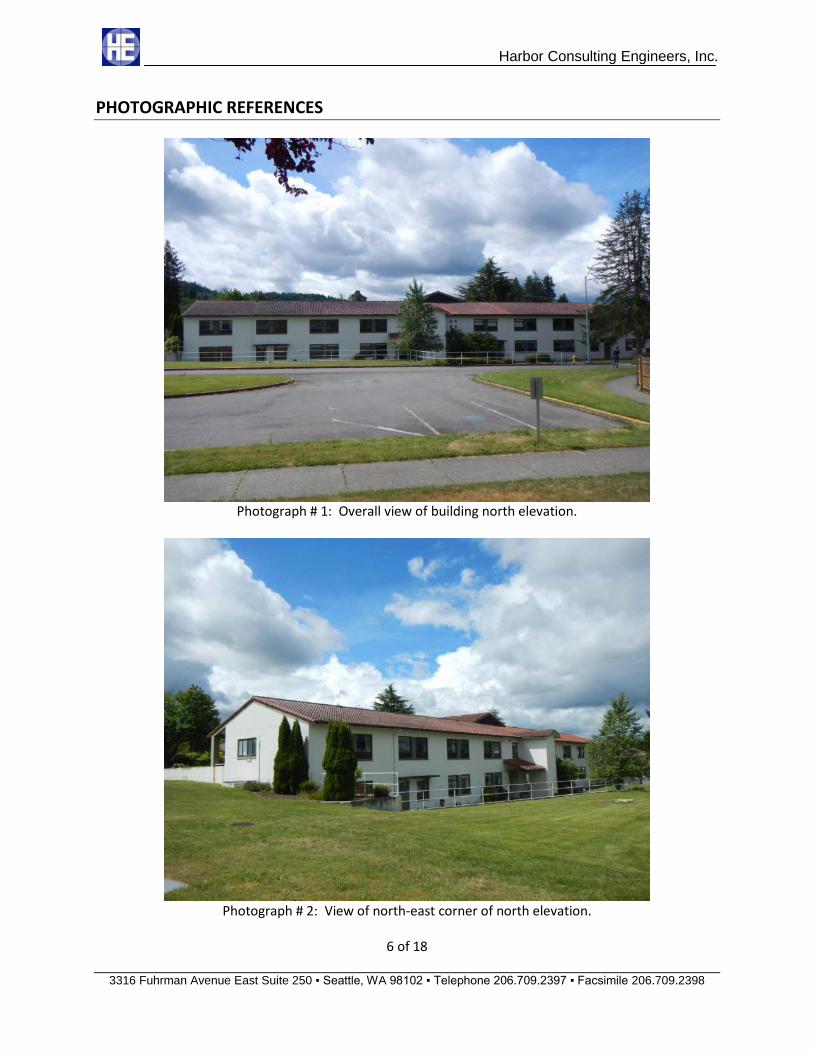
1. Overall orientation view of the building’s north elevation depicting the approximate 224 foot wide dimension. See photograph # 1
2. View of the north-east corner of the building. See photograph # 2.
3. View of the north-west corner of the building. See photograph # 3.
4. Roof decking exposed at corner porch recesses. See photograph # 4.
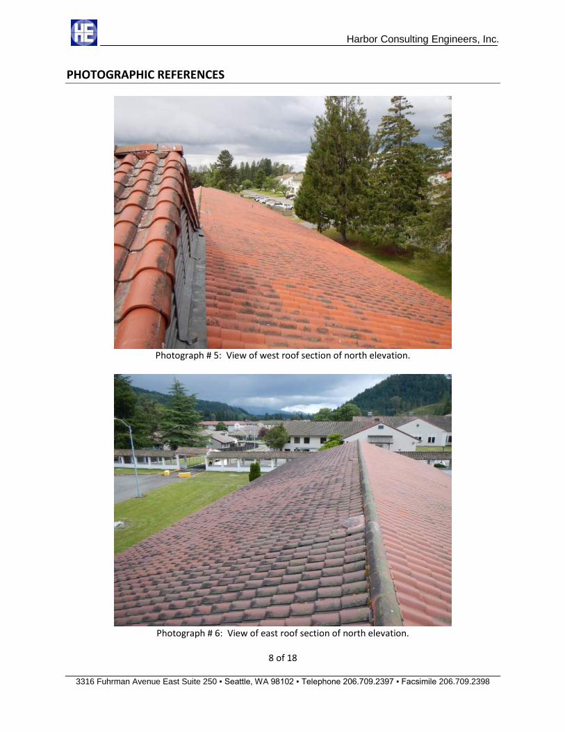
5. View of the west half of the northern section of roof just in front of the gable end vent. See photograph # 5.
6. View of the east half of the roof just beyond the gable end vent. See photograph # 6.
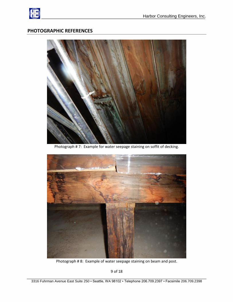
7. Example of water seepage staining noted on the soffit of the timber roof decking. See photograph # 7.
8. Example of water seepage staining noted on the beam and post supporting the roof. See photograph # 8.
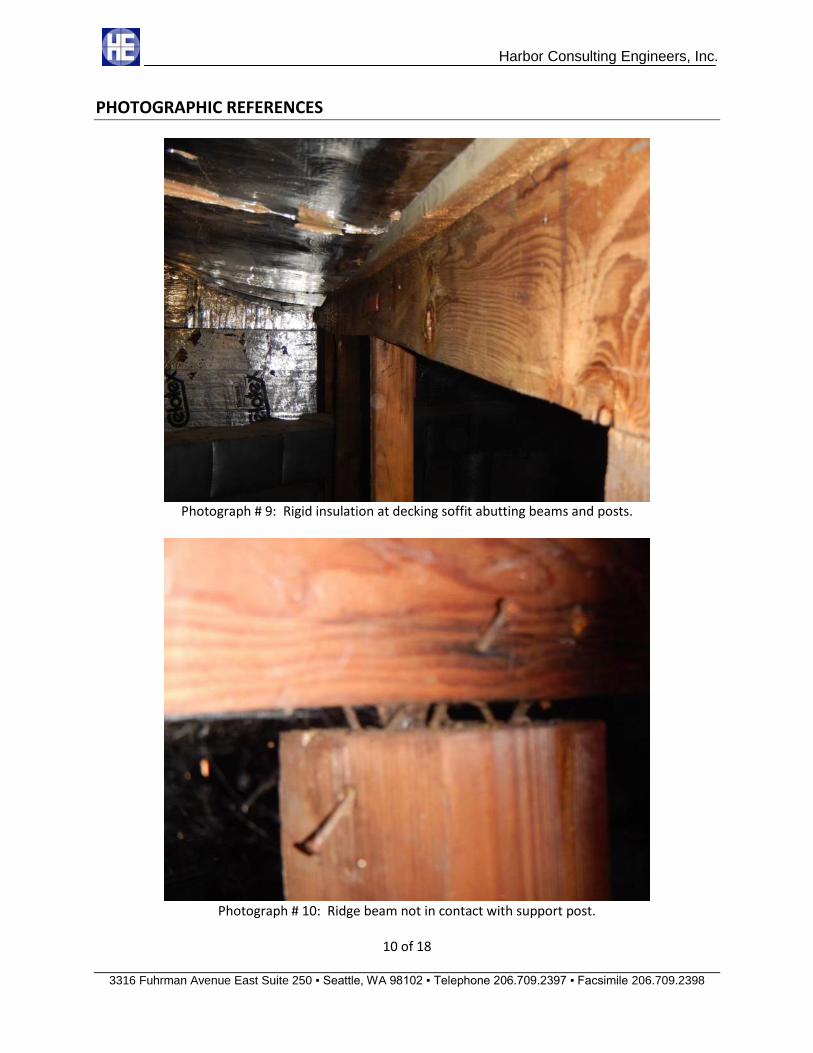
9. Typical rigid insulation installed below the roof decking with beam and post. See photograph # 9.
10. Timber post not in contact with ridge beam in the western attic chamber. See photograph # 10.
2 of 18
Harbor Consulting Engineers, Inc.
3316 Fuhrman Avenue East Suite 250 ▪ Seattle, WA 98102 ▪ Telephone 206.709.2397 ▪ Facsimile 206.709.2398
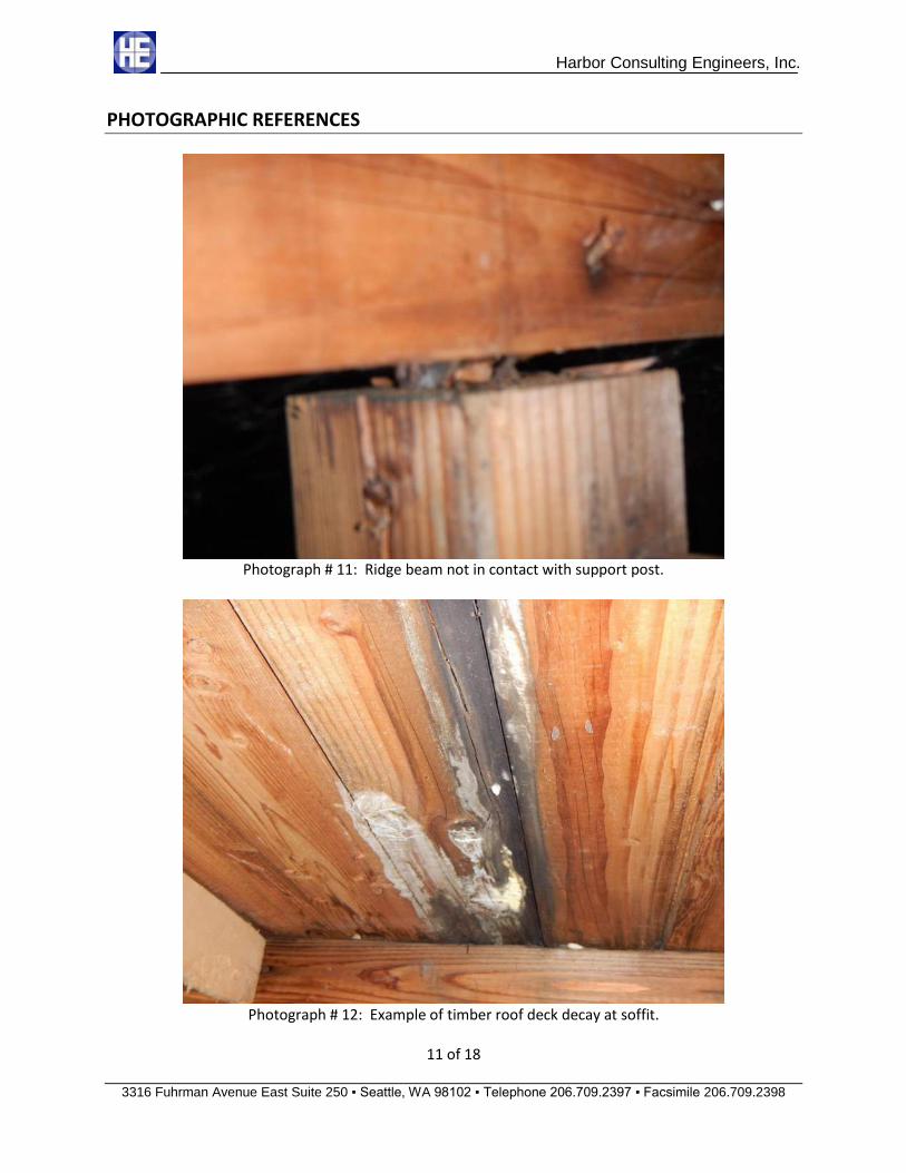
11. Timber post not in contact with the ridge beam in the western attic chamber. See photograph # 11.
12. Fungal decay growth noted at removed insulation panel at the western attic chamber. See photograph # 12.
13. Timber post not in contact with ridge beam in the western attic chamber. See photograph # 13.
14. View of roof and support framing in the central attic chamber note the non-plumb posts and curved beams. See photograph # 14.
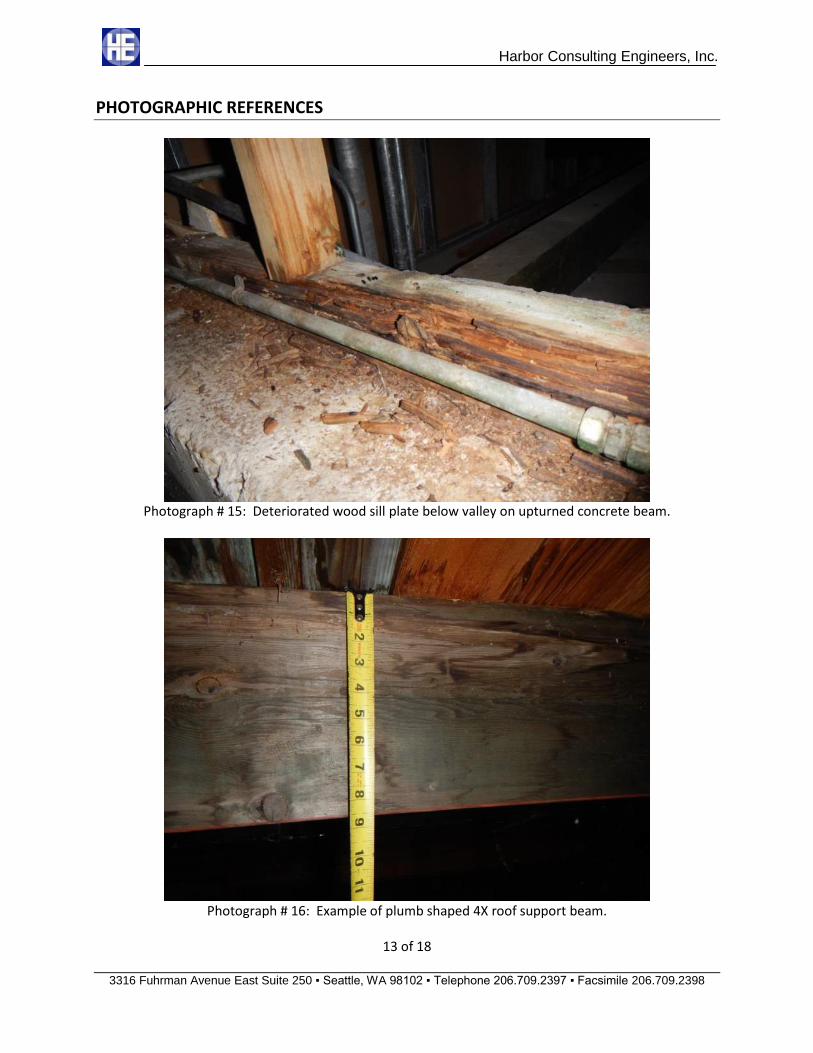
15. Decayed and deteriorated sill plate below the western valley of the central roof chamber. See photograph # 15.
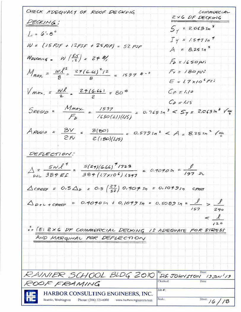
16. Example of plumb installation of 4X10 beams shaped at the top to receive roof decking. See photograph # 16.
17. Example of roof seepage staining noted at the western attic chamber. See photograph # 17.
18. Example of short post repair at upturned concrete beam in the western attic chamber. See photograph # 18.
19. High separation of ridge beam from supporting post found in the western attic chamber. See photograph # 19.
20. The attic roof vents were covered by post-original construction installed rigid insulation panels. No attic ventilation was noted in the northern attic section.
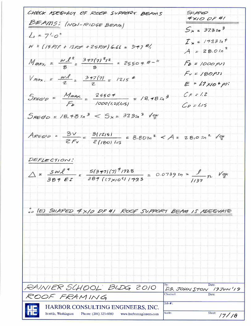
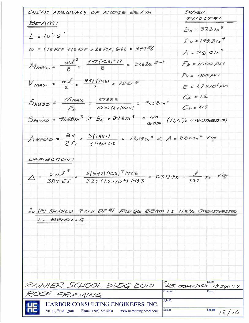
ADDITIONAL SITE VISIT ITEMS AND DISCUSSION The deformation of the shaped 4X10 nominal roof beams and the added post supports indicates a long term framing member creep issue with the roof structure. Harbor has performed structural evaluation analysis of the roof decking, roof beams, and support posts to determine member performance level. The structural analysis performed by Harbor is attached. The structural analysis revealed that the timber roof decking is adequate for bending stress and shear stress. However, the 2X6 tongue and groove roof decking is marginally over-deflected. With creep effects considered the long term total load deflection of the 2X6 roof decking is L/157 in a simple span installation. The shaped 4X10 support beams were determined to be adequate for locations with added post supports on a maximum 7 foot span in a simple span installation. The shaped 4X10 ridge beam was found to be 11.5 percent over-stressed in bending on a 10.5 foot span in a simple span installation. Observed beam deformations are higher than predicted by structural analysis due to high moisture content in the wood at roof leak areas over time resulting in increased deflections. Support posts are adequate by inspection but should be installed plumb in both directions. Locations where roof decking and support beams are installed as a continuous member over intermediate supports will result in decreased calculated deflections.
3 of 18

Harbor Consulting Engineers, Inc.
3316 Fuhrman Avenue East Suite 250 ▪ Seattle, WA 98102 ▪ Telephone 206.709.2397 ▪ Facsimile 206.709.2398
The incomplete ridge beam bearing on support posts is also an unusual framing member deformation. Some possible explanations for the observed upward vertical displacement of the ridge beam are as follows:
1) The roof decking has sufficient stiffness to deflect upwards. 2) The ridge beam has contracted over time from its full installed dimension due to long term and high degree of wood shrinkage. 3) The posts were installed loose and short. 4) Roof decking is functioning as an unintended force triangle tied by the concrete ceiling and braced by the intermediate supports at 1/6 points of the short building dimension. The likely explanation is item #4 above the force triangle. As the main sections of the roof framing settle downward on their beam support lines, each heel is restrained at the side walls. Compression at the ridge is balanced and since the roof slope is moderate the vertical component of ridge compression is greater than the dead load of the roof resulting in a net upward movement. If the roof decking were cut over the first beam at each side of the ridge the decking would slide down the roof plane and bear on the ridge beam.
Many of the support beams lines show pronounced curvature deformation even with the added timber posts. The range of movement the roof has experienced may have damaged the roofing underlayment materials leading to leakage and water damage. During the site visit a rain storm passed over the campus and active water leaks in the attic were noted. A section of the north elevation of the roof downslope from the Dutch hip containing the gable end louver was found to have sections of replaced roof decking and roof tiles.
RECOMMENDATIONS FOR REPAIR AND REHABILITATION Suggested structural repairs for the timber roof framing made in this report are intended to improve the structural performance of the timber roof system to support superimposed dead and live loads. There are several areas to address in the repair and rehabilitation of the roof framing system, these consist of the following:
1) Replace decayed or damaged roof decking and timber support beams. In conjunction with a re-roofing project the roof decking should be exposed and reviewed for signs of fungal decay. Damaged decking members should be replaced with preservative treated decking matching the dimensions of the original decking. Replacement decking should be installed in a minimum two-span layup with bearing on supports only. Support beams in the attic where deteriorated or severely deformed should be replaced with shaped 4X12 Douglas-Fir # 1 and Better to help stiffen the roof support.
2) Stiffen roof support beams to reduce deflection. In conjunction with a re-roofing project the
existing shaped 4X10 roof beams could be replaced with shaped 4X12 Douglas-Fir # 1 and Better members to reduce deflections of the roof. Alternately, the existing shaped 4X10 roof beams could have 2X10 members sistered on each side with support cleats on posts to increase the support beam stiffness and reduce roof framing deflections. The 2X10 sistering will only help
4 of 18
Harbor Consulting Engineers, Inc.
3316 Fuhrman Avenue East Suite 250 ▪ Seattle, WA 98102 ▪ Telephone 206.709.2397 ▪ Facsimile 206.709.2398
with applied loads since long term stress has already deformed the shaped 4X10 members.
3) Install positive connection hardware to resist uplift and lateral displacement of support beams. Economical light gauge post caps can be installed between the roof beams and posts.
4) Install positive connection hardware to resist uplift and lateral displacement of posts at the
concrete attic support slab. Post bases can be installed at the base of posts to sill plates and the concrete structural ceiling slab to anchor the post against uplift and lateral displacement.
5) Retrofit the attic space with ventilation meeting the requirements of the 2015 International Building Code to protect the timber roof framing members from deterioration.
Please call our office should you have any questions regarding this report or any of its recommendations.
HARBOR CONSULTING ENGINEERS, INC. Darren S. Johnston, P.E., S.E. Senior Project Manager
5 of 18
Harbor Consulting Engineers, Inc.
3316 Fuhrman Avenue East Suite 250 ▪ Seattle, WA 98102 ▪ Telephone 206.709.2397 ▪ Facsimile 206.709.2398
PHOTOGRAPHIC REFERENCES
Photograph # 1: Overall view of building north elevation.
Photograph # 2: View of north-east corner of north elevation.
6 of 18

Harbor Consulting Engineers, Inc.
3316 Fuhrman Avenue East Suite 250 ▪ Seattle, WA 98102 ▪ Telephone 206.709.2397 ▪ Facsimile 206.709.2398
PHOTOGRAPHIC REFERENCES
Photograph # 3: View of north-west corner of north elevation.
Photograph # 4: Exposed roof decking at corner porch recesses.
7 of 18
Harbor Consulting Engineers, Inc.
3316 Fuhrman Avenue East Suite 250 ▪ Seattle, WA 98102 ▪ Telephone 206.709.2397 ▪ Facsimile 206.709.2398
PHOTOGRAPHIC REFERENCES
Photograph # 5: View of west roof section of north elevation.
Photograph # 6: View of east roof section of north elevation.
8 of 18
Harbor Consulting Engineers, Inc.
3316 Fuhrman Avenue East Suite 250 ▪ Seattle, WA 98102 ▪ Telephone 206.709.2397 ▪ Facsimile 206.709.2398
PHOTOGRAPHIC REFERENCES
Photograph # 7: Example for water seepage staining on soffit of decking.
Photograph # 8: Example of water seepage staining on beam and post.
9 of 18
Harbor Consulting Engineers, Inc.
3316 Fuhrman Avenue East Suite 250 ▪ Seattle, WA 98102 ▪ Telephone 206.709.2397 ▪ Facsimile 206.709.2398
PHOTOGRAPHIC REFERENCES
Photograph # 9: Rigid insulation at decking soffit abutting beams and posts.
Photograph # 10: Ridge beam not in contact with support post.
10 of 18
Harbor Consulting Engineers, Inc.
3316 Fuhrman Avenue East Suite 250 ▪ Seattle, WA 98102 ▪ Telephone 206.709.2397 ▪ Facsimile 206.709.2398
PHOTOGRAPHIC REFERENCES
Photograph # 11: Ridge beam not in contact with support post.
Photograph # 12: Example of timber roof deck decay at soffit.
11 of 18

Harbor Consulting Engineers, Inc.
3316 Fuhrman Avenue East Suite 250 ▪ Seattle, WA 98102 ▪ Telephone 206.709.2397 ▪ Facsimile 206.709.2398
PHOTOGRAPHIC REFERENCES
Photograph # 13: Ridge beam not in contact with support post.
Photograph # 14: View of attic framing with rigid insulation (note non-plumb posts)
12 of 18
Harbor Consulting Engineers, Inc.
3316 Fuhrman Avenue East Suite 250 ▪ Seattle, WA 98102 ▪ Telephone 206.709.2397 ▪ Facsimile 206.709.2398
PHOTOGRAPHIC REFERENCES
Photograph # 15: Deteriorated wood sill plate below valley on upturned concrete beam.
Photograph # 16: Example of plumb shaped 4X roof support beam.
13 of 18

Harbor Consulting Engineers, Inc.
3316 Fuhrman Avenue East Suite 250 ▪ Seattle, WA 98102 ▪ Telephone 206.709.2397 ▪ Facsimile 206.709.2398
PHOTOGRAPHIC REFERENCES
Photograph # 17: Example of seepage staining on soffit of roof decking and support beams.
Photograph # 18: Repair of short timber post on upturned concrete beam.
14 of 18

Harbor Consulting Engineers, Inc.
3316 Fuhrman Avenue East Suite 250 ▪ Seattle, WA 98102 ▪ Telephone 206.709.2397 ▪ Facsimile 206.709.2398
PHOTOGRAPHIC REFERENCES
Photograph # 19: High beam separation from post of 3/4 inch.
15 or 18
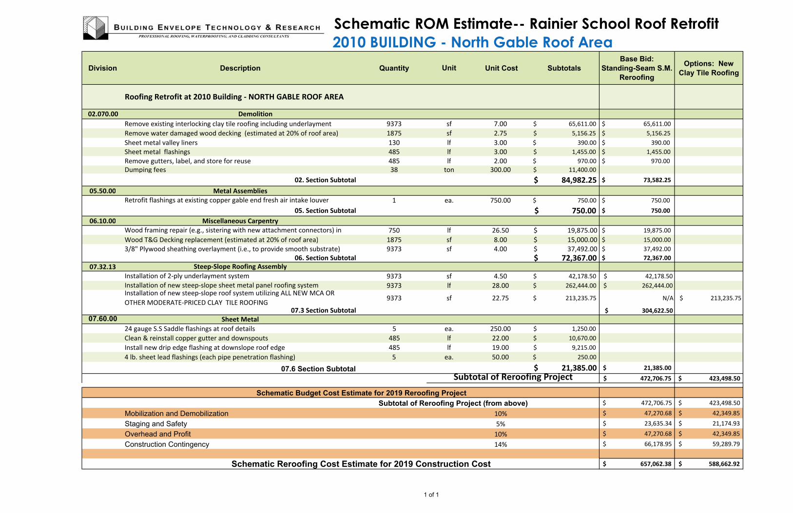
Schematic ROM Estimate-- Rainier School Roof Retrofit
2010 BUILDING - North Gable Roof Area
Division Description Quantity Unit Cost Subtotals
Base Bid:
Standing-Seam S.M.
Reroofing
Options: New
Clay Tile Roofing
Remove existing interlocking clay tile roofing including underlayment 9373 sf 7.00 $ 65,611.00 $ 65,611.00
Remove water damaged wood decking (estimated at 20% of roof area) 1875 sf 2.75 $ 5,156.25 $ 5,156.25
Sheet metal valley liners 130 lf 3.00 $ 390.00 $ 390.00
Sheet metal flashings 485 lf 3.00 $ 1,455.00 $ 1,455.00
Remove gutters, label, and store for reuse 485 lf 2.00 $ 970.00 $ 970.00
Dumping fees 38 ton 300.00 $ 11,400.00
2 02. Section Subtotal $ 84,982.25 $ 73,582.25
05.50.00 Metal Assemblies
1 ea. 750.00 $ 750.00 $ 750.00
05. Section Subtotal $ 750.00 $ 750.00
06.10.00 Miscellaneous Carpentry
750 lf 26.50 $ 19,875.00 $ 19,875.00
Wood T&G Decking replacement (estimated at 20% of roof area) 1875 sf 8.00 $ 15,000.00 $ 15,000.00
3/8" Plywood sheathing overlayment (i.e., to provide smooth substrate) 9373 sf 4.00 $ 37,492.00 $ 37,492.00
06. Section Subtotal $ 72,367.00 $ 72,367.00
07.32.13
9373 sf 4.50 $ 42,178.50 $ 42,178.50
9373 lf 28.00 $ 262,444.00 $ 262,444.00
9373 sf 22.75 $ 213,235.75 N/A $ 213,235.75
$ 304,622.50
07.60.00
24 gauge S.S Saddle flashings at roof details 5 ea. 250.00 $ 1,250.00
Clean & reinstall copper gutter and downspouts 485 lf 22.00 $ 10,670.00
Install new drip edge flashing at downslope roof edge 485 lf 19.00 $ 9,215.00
4 lb. sheet lead flashings (each pipe penetration flashing) 5 ea. 50.00 $ 250.00
07.6 Section Subtotal $ 21,385.00 21,385.00$
$ 472,706.75 $ 423,498.50
$ 472,706.75 $ 423,498.50
Mobilization and Demobilization 10% $ 47,270.68 $ 42,349.85
Staging and Safety 5% $ 23,635.34 $ 21,174.93
Overhead and Profit 10% $ 47,270.68 $ 42,349.85
Construction Contingency 14% $ 66,178.95 $ 59,289.79
657,062.38$ 588,662.92$ Schematic Reroofing Cost Estimate for 2019 Construction Cost
Schematic Budget Cost Estimate for 2019 Reroofing Project
Subtotal of Reroofing Project (from above)
Sheet Metal
Subtotal of Reroofing Project
Unit
02.070.00 Demolition
Roofing Retrofit at 2010 Building - NORTH GABLE ROOF AREA
Installation of new steep-slope roof system utilizing ALL NEW MCA OR
OTHER MODERATE-PRICED CLAY TILE ROOFING07.3 Section Subtotal
Retrofit flashings at existing copper gable end fresh air intake louver
Wood framing repair (e.g., sistering with new attachment connectors) in
Steep-Slope Roofing Assembly
Installation of 2-ply underlayment system
Installation of new steep-slope sheet metal panel roofing system
1 of 1
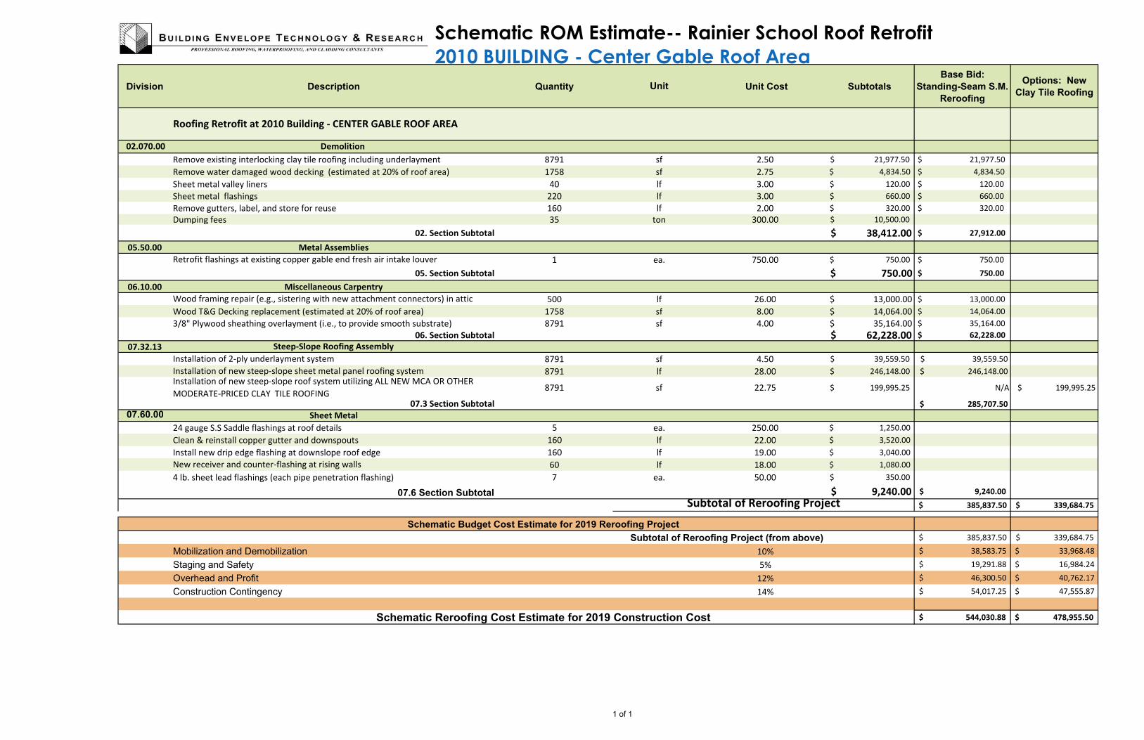
Schematic ROM Estimate-- Rainier School Roof Retrofit
2010 BUILDING - Center Gable Roof Area
Division Description Quantity Unit Cost Subtotals
Base Bid:
Standing-Seam S.M.
Reroofing
Options: New
Clay Tile Roofing
Remove existing interlocking clay tile roofing including underlayment 8791 sf 2.50 $ 21,977.50 $ 21,977.50
Remove water damaged wood decking (estimated at 20% of roof area) 1758 sf 2.75 $ 4,834.50 $ 4,834.50
Sheet metal valley liners 40 lf 3.00 $ 120.00 $ 120.00
Sheet metal flashings 220 lf 3.00 $ 660.00 $ 660.00
Remove gutters, label, and store for reuse 160 lf 2.00 $ 320.00 $ 320.00
Dumping fees 35 ton 300.00 $ 10,500.00
2 02. Section Subtotal $ 38,412.00 $ 27,912.00
05.50.00 Metal Assemblies
1 ea. 750.00 $ 750.00 $ 750.00
05. Section Subtotal $ 750.00 $ 750.00
06.10.00 Miscellaneous Carpentry
500 lf 26.00 $ 13,000.00 $ 13,000.00
Wood T&G Decking replacement (estimated at 20% of roof area) 1758 sf 8.00 $ 14,064.00 $ 14,064.00
3/8" Plywood sheathing overlayment (i.e., to provide smooth substrate) 8791 sf 4.00 $ 35,164.00 $ 35,164.00
06. Section Subtotal $ 62,228.00 $ 62,228.00
07.32.13
8791 sf 4.50 $ 39,559.50 $ 39,559.50
8791 lf 28.00 $ 246,148.00 $ 246,148.00
8791 sf 22.75 $ 199,995.25 N/A $ 199,995.25
$ 285,707.50
07.60.00
24 gauge S.S Saddle flashings at roof details 5 ea. 250.00 $ 1,250.00
Clean & reinstall copper gutter and downspouts 160 lf 22.00 $ 3,520.00
Install new drip edge flashing at downslope roof edge 160 lf 19.00 $ 3,040.00
60 lf 18.00 $ 1,080.00
4 lb. sheet lead flashings (each pipe penetration flashing) 7 ea. 50.00 $ 350.00
07.6 Section Subtotal $ 9,240.00 9,240.00$
$ 385,837.50 $ 339,684.75
$ 385,837.50 $ 339,684.75
Mobilization and Demobilization 10% $ 38,583.75 $ 33,968.48
Staging and Safety 5% $ 19,291.88 $ 16,984.24
Overhead and Profit 12% $ 46,300.50 $ 40,762.17
Construction Contingency 14% $ 54,017.25 $ 47,555.87
544,030.88$ 478,955.50$
Installation of new steep-slope roof system utilizing ALL NEW MCA OR OTHER
MODERATE-PRICED CLAY TILE ROOFING
Unit
Roofing Retrofit at 2010 Building - CENTER GABLE ROOF AREA
02.070.00 Demolition
Retrofit flashings at existing copper gable end fresh air intake louver
Wood framing repair (e.g., sistering with new attachment connectors) in attic
Steep-Slope Roofing Assembly
Installation of 2-ply underlayment system
Installation of new steep-slope sheet metal panel roofing system
Schematic Reroofing Cost Estimate for 2019 Construction Cost
07.3 Section Subtotal
Sheet Metal
New receiver and counter-flashing at rising walls
Subtotal of Reroofing Project
Schematic Budget Cost Estimate for 2019 Reroofing Project
Subtotal of Reroofing Project (from above)
1 of 1

Copyright © 2019 Building Envelope Technology & Research
Page 1 of 11
APPENDIX C: ADDITIONAL CAMPUS BUILDINGS IDENTIFIED WITH SEVERE
WATER INTRUSION ISSUES NEEDING REPAIR, RETROFIT, AND REPLACEMENT
Along with the roof survey of the 2010 Building, Rainier School personnel and the State of Washington
DSHS PM, provided a partial list of other campus buildings that have experienced severe long-term
water intrusion issues. Although a survey has not been conducted to determine the leak sources and
assessment of potential roofing and interior damages, this writer conducted an exterior walk-around
survey to photograph exterior conditions in order to compile a partial list of other campus buildings
requiring additional survey and condition assessment work. BET&R can assist Rainier School and the
DSHS with preparing a prioritized list of repair, retrofit, or reroofing projects following more in-depth
survey and analysis of these and other buildings. The following set of photos identifies and provides a
brief description of the individual buildings including preliminary information related to the subject
buildings and potential prioritization of importance.
In general, the campus buildings that have low-slope roof areas are currently roofed with aged, single-
ply roof membranes that are at the end of their useful service life. From previous surveys on other
buildings, and reports from Rainier School personnel, the existing low-slope roof areas consist of a
Hypalon single-ply roofing membrane. It appears that many of these low-slope roof membranes were
installed at least 20-30 years ago, have reached the end of their service life, and are in need of
replacement in the near future as budget allows. As Hypalon ages, the roof membrane surface coating
typically deteriorates, exposing the internal reinforcing scrim within the single-ply membrane sheet,
which may allow rain water to wick into and through the roofing membrane system. It is
recommended that these single-ply roof membranes be replaced before complete failure of the aged
membranes occur. BET&R recommends replacement of the single-ply roof membranes with a
multiple-ply SBS-modified asphalt roof membrane system. We have successfully reroofed the low-
slope roof area at the Auditorium in 2017 with a multi-ply SBS-modified asphalt roofing membrane
system, manufactured by Soprema, that is economical and could serve as a baseline benchmark roofing
system that Rainier School could rely on for many years of weather and water-tight service. With
proper maintenance and application of a coating system at appropriate intervals of the service life,
multiple-ply SBS-modified asphalt roofing membranes are capable of providing 40-plus years of
successful service life.
For campus buildings with steep-slopes roofs consisting of clay roofing tiles, BET&R has successfully
worked with Rainier School to reroof buildings, including the steep-slope portions of the Auditorium
Building, or repaired select portions of the roofs by carefully removing existing pan-and-cover clay tile
roofing, conducting repairs as needed, and them installing a new underlayment system followed by
reinstalling the existing clay roof tiles. This has proved to be an effective method to repair and renew
the older pan-and-cover clay tile roof areas. We have also replaced building roofs and select roof areas
with SBS-modified asphalt shingles, and have also considered sheet metal panel standing seam roof
systems for potential roof replacement.

Rainier School, State of Washington DSHS
Appendix C: Identified Rainier School Buildings With Water Intrusion Issues
Buckley, WA
June 28, 2019
Copyright © 2019 Building Envelope Technology & Research
Page 2 of 11
Depending on the building and existing roof system on specific campus buildings, appropriate cost-
affective, long-term roofing system can be selected, designed, and installed to extend the service life of
these campus buildings. The high-quality original construction for the older campus buildings is
evident and with economical roof repair and replacement projects, where needed, the buildings can
remain functional for many more years. Conducting roof repairs and replacement before further
water-damage, decay, and deterioration occurs is critical to preserve the buildings and is a prudent use
of resources as future repair and replacement costs will only escalate as deterioration persists and is
allowed to continue. Having a leak-free roof system is one of the first and most critical building
envelope components that needs to be maintained to sustain the service life of any building, as roofs
are the first line of defense in the Pacific Northwest’s often rainy, temperate climate.
Figure 1 -- In this overview map, campus buildings photographed for this appendix have been identified for
reference.
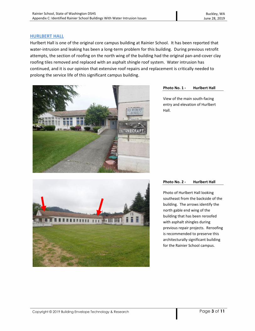
Rainier School, State of Washington DSHS
Appendix C: Identified Rainier School Buildings With Water Intrusion Issues
Buckley, WA
June 28, 2019
Copyright © 2019 Building Envelope Technology & Research
Page 3 of 11
HURLBERT HALL
Hurlbert Hall is one of the original core campus building at Rainier School. It has been reported that
water-intrusion and leaking has been a long-term problem for this building. During previous retrofit
attempts, the section of roofing on the north wing of the building had the original pan-and-cover clay
roofing tiles removed and replaced with an asphalt shingle roof system. Water intrusion has
continued, and it is our opinion that extensive roof repairs and replacement is critically needed to
prolong the service life of this significant campus building.
Photo No. 1 - Hurlbert Hall
View of the main south-facing
entry and elevation of Hurlbert
Hall.
Photo No. 2 - Hurlbert Hall
Photo of Hurlbert Hall looking
southeast from the backside of the
building. The arrows identify the
north gable end wing of the
building that has been reroofed
with asphalt shingles during
previous repair projects. Reroofing
is recommended to preserve this
architecturally significant building
for the Rainier School campus.
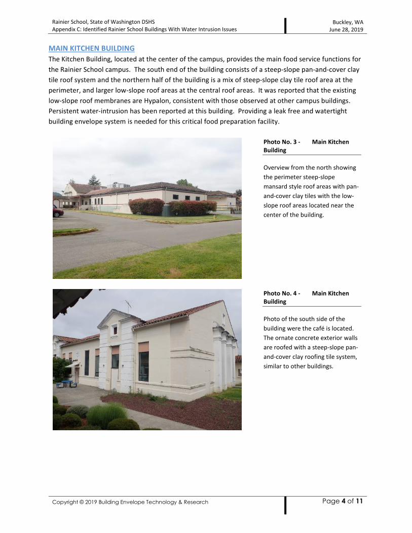
Rainier School, State of Washington DSHS
Appendix C: Identified Rainier School Buildings With Water Intrusion Issues
Buckley, WA
June 28, 2019
Copyright © 2019 Building Envelope Technology & Research
Page 4 of 11
MAIN KITCHEN BUILDING
The Kitchen Building, located at the center of the campus, provides the main food service functions for
the Rainier School campus. The south end of the building consists of a steep-slope pan-and-cover clay
tile roof system and the northern half of the building is a mix of steep-slope clay tile roof area at the
perimeter, and larger low-slope roof areas at the central roof areas. It was reported that the existing
low-slope roof membranes are Hypalon, consistent with those observed at other campus buildings.
Persistent water-intrusion has been reported at this building. Providing a leak free and watertight
building envelope system is needed for this critical food preparation facility.
Photo No. 3 - Main Kitchen
Building
Overview from the north showing
the perimeter steep-slope
mansard style roof areas with pan-
and-cover clay tiles with the low-
slope roof areas located near the
center of the building.
Photo No. 4 - Main Kitchen
Building
Photo of the south side of the
building were the café is located.
The ornate concrete exterior walls
are roofed with a steep-slope pan-
and-cover clay roofing tile system,
similar to other buildings.

Rainier School, State of Washington DSHS
Appendix C: Identified Rainier School Buildings With Water Intrusion Issues
Buckley, WA
June 28, 2019
Copyright © 2019 Building Envelope Technology & Research
Page 5 of 11
MAINTENANCE BUILDING
Similar to the older, original campus buildings, the Maintenance Building is a largely composed of
concrete. The existing low-slope roof membrane is reportedly an aged single-ply Hypalon roofing
membrane. Rain water leaks have been reported at numerous areas and it is our opinion that due to
the age, existing membrane condition, and reports of water intrusion, it is prudent to consider roof
replacement with a new multiple-ply roofing membrane system. This Project Team has successfully
designed, specified, and administered the construction phase and installation, in conjunction with
qualified roofing contractors, with a new low-slope multiple-ply SBS-modified asphalt roofing
membrane system. Replacement of the aged single-ply Hypalon roof membranes should be prioritized
as high importance.
Photo No. 5 - Maintenance
Building
Overview looking east towards the
Maintenance Building.
Photo No. 6 - Maintenance
Building
Photo depicting the series of low-
slope roof areas needing
replacement prior to failure of the
existing roof membrane system.
The building currently experiences
rain water intrusion leaks at
several locations.

Rainier School, State of Washington DSHS
Appendix C: Identified Rainier School Buildings With Water Intrusion Issues
Buckley, WA
June 28, 2019
Copyright © 2019 Building Envelope Technology & Research
Page 6 of 11
POWER HOUSE
The Power House also consists of a single-ply Hypalon roofing membrane at the various roof levels of
the building. Although we have not closely surveyed the roof areas, it is evident from a distance that
the existing roof membrane has deteriorated and is in need of replacement. Providing power to the
campus, this building serves a critical function for the entire facility.
Photo No. 7 - Power House
Building
Overview from the P-43 Building
looking southwest towards the
Power House. The low-slope
single-ply Hypalon membrane was
extended and rolled over the
perimeter edge of the identified
roof area. Visual evidence, even
from this distance, showed that
the existing membrane is aged, has
deteriorated, and is recommended
for replacement, as the membrane
has reached the end of its useful
service life.
Photo No. 8 - Power House
Building Low-Slope Roof
Close-up view of the existing
single-ply Hypalon membrane at
the east end roof area, identified
above. Areas of ponding are
evident and the edge of the
membrane shows signs of
deterioration and is recommended
for replacement.
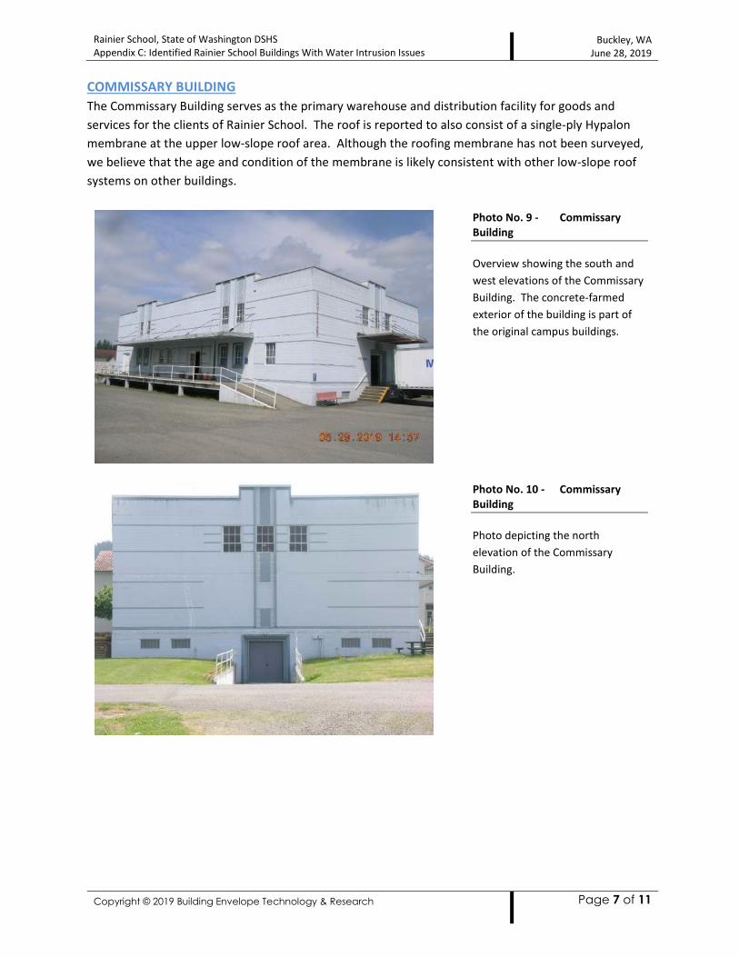
Rainier School, State of Washington DSHS
Appendix C: Identified Rainier School Buildings With Water Intrusion Issues
Buckley, WA
June 28, 2019
Copyright © 2019 Building Envelope Technology & Research
Page 7 of 11
COMMISSARY BUILDING
The Commissary Building serves as the primary warehouse and distribution facility for goods and
services for the clients of Rainier School. The roof is reported to also consist of a single-ply Hypalon
membrane at the upper low-slope roof area. Although the roofing membrane has not been surveyed,
we believe that the age and condition of the membrane is likely consistent with other low-slope roof
systems on other buildings.
Photo No. 9 - Commissary
Building
Overview showing the south and
west elevations of the Commissary
Building. The concrete-farmed
exterior of the building is part of
the original campus buildings.
Photo No. 10 - Commissary
Building
Photo depicting the north
elevation of the Commissary
Building.
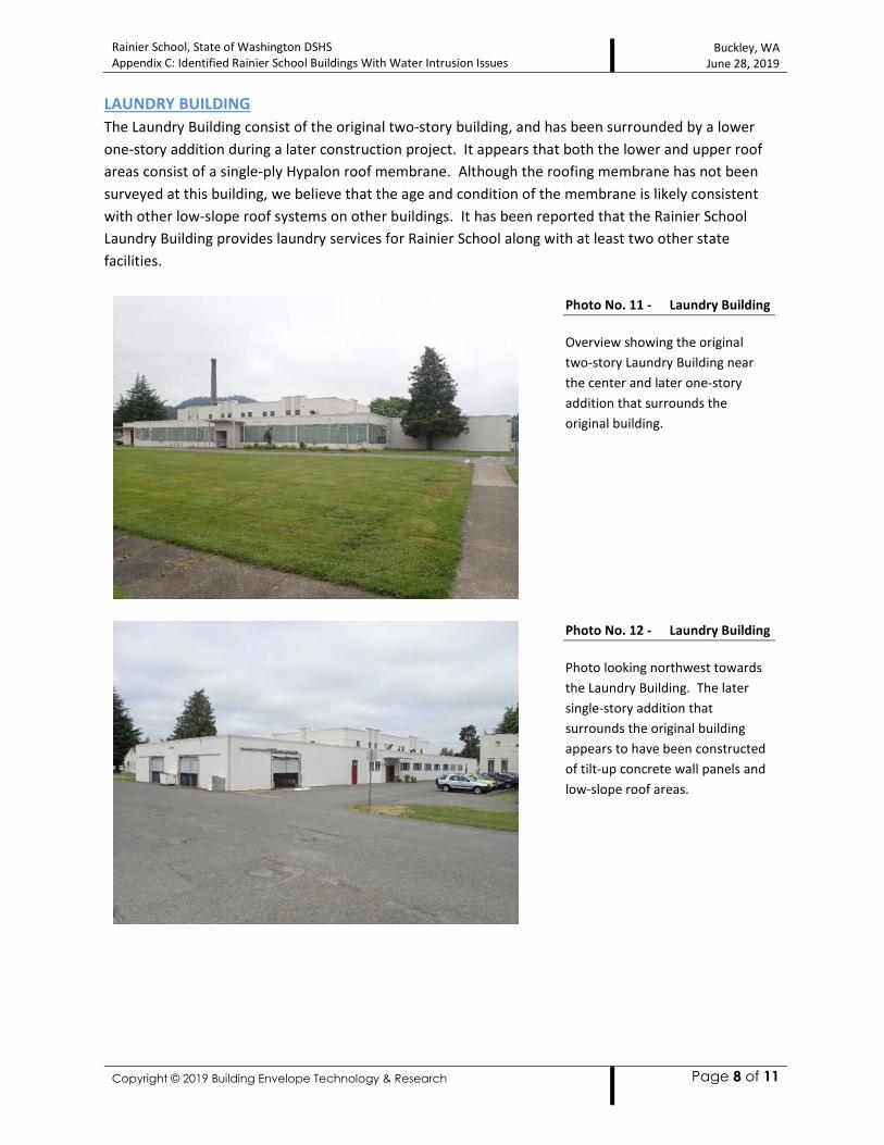
Rainier School, State of Washington DSHS
Appendix C: Identified Rainier School Buildings With Water Intrusion Issues
Buckley, WA
June 28, 2019
Copyright © 2019 Building Envelope Technology & Research
Page 8 of 11
LAUNDRY BUILDING
The Laundry Building consist of the original two-story building, and has been surrounded by a lower
one-story addition during a later construction project. It appears that both the lower and upper roof
areas consist of a single-ply Hypalon roof membrane. Although the roofing membrane has not been
surveyed at this building, we believe that the age and condition of the membrane is likely consistent
with other low-slope roof systems on other buildings. It has been reported that the Rainier School
Laundry Building provides laundry services for Rainier School along with at least two other state
facilities.
Photo No. 11 - Laundry Building
Overview showing the original
two-story Laundry Building near
the center and later one-story
addition that surrounds the
original building.
Photo No. 12 - Laundry Building
Photo looking northwest towards
the Laundry Building. The later
single-story addition that
surrounds the original building
appears to have been constructed
of tilt-up concrete wall panels and
low-slope roof areas.

Rainier School, State of Washington DSHS
Appendix C: Identified Rainier School Buildings With Water Intrusion Issues
Buckley, WA
June 28, 2019
Copyright © 2019 Building Envelope Technology & Research
Page 9 of 11
CARPENTRY SHOP
The Carpentry Shop is currently roofed with a low-slope sheet metal panel standing seam roof system.
Numerous interior leaks have been reported and are recommended to be addressed. Additional
survey is needed to better understand the source or water intrusion to assist with proper design and
specification of roofing related repairs.
Photo No. 13 - Carpentry Shop
Overview depicting the existing
Carpentry Shop at Rainier School
showing the low-slope roof profile
at the gable end.
Photo No. 14 - Carpentry Shop
Interior
Several interior leak locations were
reported. This photo shows
interior ceiling damage due to on-
going water intrusion.

Rainier School, State of Washington DSHS
Appendix C: Identified Rainier School Buildings With Water Intrusion Issues
Buckley, WA
June 28, 2019
Copyright © 2019 Building Envelope Technology & Research
Page 10 of 11
ADLER HALL AND OTHER BUIDLINGS WITHIN THIS RESIDENTIAL QUAD
BET&R has been privileged to work on a number of buildings on the Rainier School campus, providing
us with valuable experience and technical information specifically related to the building envelope
systems of these historic buildings as well as the construction methods and structural framing systems
observed on other buildings. Our history on-site includes work on the following buildings.
Photo No. 15 - Adler Hall and
other Residence Buildings
Photo depicting extensive roof
damage at Adler Hall. Reroofing
and replacement of damaged roof
structure members is
recommended for this building and
the other buildings that create a
four-building quad. While roof
replacement work may be
extensive, the high-quality
construction of the main building
structure is worth protecting on
our opinion.
Photo No. 16 - Adler Hall and
other Residence Buildings
Photo provided by the State of
Washington from the attic spaces
within these residential buildings.
Note that the tongue-and-groove
roof decking runs parallel with the
slope of the roof. It is likely that
much of the damage and decay is
isolated to the roof decking and
the primary, large-dimension wood
framed structural support
members remain largely intact and
serviceable for reroofing.
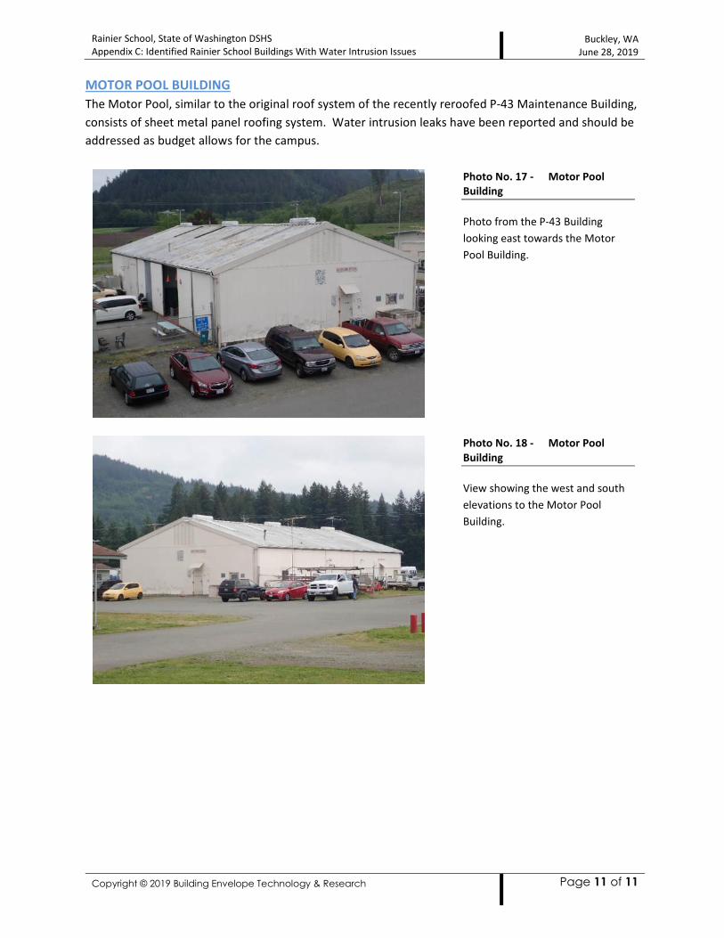
Rainier School, State of Washington DSHS
Appendix C: Identified Rainier School Buildings With Water Intrusion Issues
Buckley, WA
June 28, 2019
Copyright © 2019 Building Envelope Technology & Research
Page 11 of 11
MOTOR POOL BUILDING
The Motor Pool, similar to the original roof system of the recently reroofed P-43 Maintenance Building,
consists of sheet metal panel roofing system. Water intrusion leaks have been reported and should be
addressed as budget allows for the campus.
Photo No. 17 - Motor Pool
Building
Photo from the P-43 Building
looking east towards the Motor
Pool Building.
Photo No. 18 - Motor Pool
Building
View showing the west and south
elevations to the Motor Pool
Building.
Related Documents