1. Introduction The limit load is one of the most critical areas of interest in deformation failures, which has been the focus of research for many years in industry. The limit load is the maximum load that a structure assuming a perfectly plastic material can sustain. The implication of this phenomenon in a structure lies in the fact that the application of a proportional load beyond the limit load, would lead to plastic collapse. The accurate identification of the limit load is essential to the design and life assessment of mechanical structures. In circumstances where structures/components are subjected to cyclic loading histories, the relative variations of the induced mechanical and thermal stresses have serious implications on the life span of the structural components. In the analysis of structures subjected to cyclic loading histories with elastic–plastic materials, the component will experience either elastic/plastic shakedown or ratchetting depending upon the applied load level. The elastic shakedown limit is the highest cyclic load under which a material shakedown to an elastic response after the first few load cycles. When the elastic shakedown limit is exceeded, the structure may experience either alternating plasticity (plastic shakedown) or ratchetting. Ratchetting should be avoided at all costs since it leads to intolerable deformation and eventual collapse of the structure. Reverse-plasticity can be endured provided low cycle fatigue is taken into ∗Corresponding author, Ph.D., E-mail: [email protected] consideration. Hence, in the design of structures, it must be ensured that any inelastic strain accumulation is avoided or restricted to the number of cycles within a designed limit so that they will not damage the structure. Limit load, shakedown and ratchet analysis of loaded structures have been investigated by many researchers in past decades, respectively. The complex nature of the shakedown, ratchet mechanism means that analytical solutions are rare to obtain. Therefore, incremental Finite Element Analysis (FEA) is widely used to determine them. Taking the cylinder with nozzle as an example, Chen et al. (2016) summarized and compare the application of different limit load methods. The results investigated that limit load determined by linearization method was the smallest. Limit load determined by twice elastic slope criterion (Chen et al. (2016) cited the references from the ASME BPVC prior to 2010) was the nearest to the experimental results. Elastic- plastic finite element analysis had comparably computational precision. But Elastic-plastic finite element analysis required considerable amount of computation time and higher processing and storage capacity of the computer. Moreover, most of criteria for limit load estimation included any human factors based on a certain substantive characteristic of experimental results. The reasonable criterion should be objective and operational. Therefore, the scholars have been trying to develop an objective and operational determined limit load method. Chen et al. (2016) reviewed pseudo-elastic finite element method which was a simple and robust methods for identifying the limit load for a component or structure. They pointed out that the robust method was found to provide good accuracy approximations of obtained limit load, can save a lot of computation time. Limit load determined by some of robust Limit load, shakedown and ratchet analysis of pressurized lateral nozzle Xiaohui Chen ∗1,2 , Kunmin Zhuang 1,3 , Xuanchen Zhu 4 and Haofeng Chen 4 1 School of Control Engineering, Northeastern University, Qinhuangdao, 066004, China 2 School of Mechanical Engineering & Automation, Yanshan University, Qinhuangdao, 066004, China 3 School of Aerospace Engineering, Xiamen University, Xiamen, 361005, China 4 Department of Mechanical & Aerospace Engineering, University of Strathclyde, G1 1XJ, UK Abstract. This paper evaluates the limit load, shakedown limit and ratchet limit of the oblique nozzle based on the linear matching method (LMM). In order to study the influencing factors of the limit load, shakedown limit and ratchet limit of the oblique nozzle, oblique nozzle models with different dip angles, diameter-to-thickness ratios of the oblique nozzle and diameter- to-thickness ratios of the main pipe are established, respectively. Firstly, the limit load, shakedown limit and ratchet limit of the oblique nozzle are studied. At the same time, the influence of the loading mode on the shakedown limit and ratchet limit is also studied. Secondly, oblique nozzles with different defect lengths, widths and depths are established, respectively. The influence of loading paths on shakedown limit and ratchet limit of oblique nozzles with defects are also studied. Finally, shakedown limit and ratchet limit diagrams are obtained based on linear matching method. The correctness of shakedown limit and ratchet limit diagrams is validated by ABAQUS incremental elastic-plastic analysis. Keywords: oblique nozzle; LMM; limit load; shakedown limit; ratchet limit 1

Welcome message from author
This document is posted to help you gain knowledge. Please leave a comment to let me know what you think about it! Share it to your friends and learn new things together.
Transcript

1. Introduction
The limit load is one of the most critical areas of interest
in deformation failures, which has been the focus of research for many years in industry. The limit load is the maximum load that a structure assuming a perfectly plastic material can sustain. The implication of this phenomenon in a structure lies in the fact that the application of a proportional load beyond the limit load, would lead to plastic collapse. The accurate identification of the limit load is essential to the design and life assessment of mechanical structures.
In circumstances where structures/components are subjected to cyclic loading histories, the relative variations of the induced mechanical and thermal stresses have serious implications on the life span of the structural components. In the analysis of structures subjected to cyclic loading histories with elastic–plastic materials, the component will experience either elastic/plastic shakedown or ratchetting depending upon the applied load level. The elastic shakedown limit is the highest cyclic load under which a material shakedown to an elastic response after the first few load cycles. When the elastic shakedown limit is exceeded, the structure may experience either alternating plasticity (plastic shakedown) or ratchetting. Ratchetting should be avoided at all costs since it leads to intolerable deformation and eventual collapse of the structure. Reverse-plasticity can be endured provided low cycle fatigue is taken into
∗Corresponding author, Ph.D., E-mail: [email protected]
consideration. Hence, in the design of structures, it must be ensured that any inelastic strain accumulation is avoided or restricted to the number of cycles within a designed limit so that they will not damage the structure.
Limit load, shakedown and ratchet analysis of loaded structures have been investigated by many researchers in past decades, respectively. The complex nature of the shakedown, ratchet mechanism means that analytical solutions are rare to obtain. Therefore, incremental Finite Element Analysis (FEA) is widely used to determine them. Taking the cylinder with nozzle as an example, Chen et al. (2016) summarized and compare the application of different limit load methods. The results investigated that limit load determined by linearization method was the smallest. Limit load determined by twice elastic slope criterion (Chen et al. (2016) cited the references from the ASME BPVC prior to 2010) was the nearest to the experimental results. Elastic-plastic finite element analysis had comparably computational precision. But Elastic-plastic finite element analysis required considerable amount of computation time and higher processing and storage capacity of the computer. Moreover, most of criteria for limit load estimation included any human factors based on a certain substantive characteristic of experimental results. The reasonable criterion should be objective and operational. Therefore, the scholars have been trying to develop an objective and operational determined limit load method. Chen et al. (2016) reviewed pseudo-elastic finite element method which was a simple and robust methods for identifying the limit load for a component or structure. They pointed out that the robust method was found to provide good accuracy approximations of obtained limit load, can save a lot of computation time. Limit load determined by some of robust
Limit load, shakedown and ratchet analysis of pressurized lateral nozzle
Xiaohui Chen∗1,2, Kunmin Zhuang 1,3, Xuanchen Zhu 4 and Haofeng Chen 4
1 School of Control Engineering, Northeastern University, Qinhuangdao, 066004, China 2 School of Mechanical Engineering & Automation, Yanshan University, Qinhuangdao, 066004, China
3 School of Aerospace Engineering, Xiamen University, Xiamen, 361005, China 4 Department of Mechanical & Aerospace Engineering, University of Strathclyde, G1 1XJ, UK
Abstract. This paper evaluates the limit load, shakedown limit and ratchet limit of the oblique nozzle based on the linear matching method (LMM). In order to study the influencing factors of the limit load, shakedown limit and ratchet limit of the oblique nozzle, oblique nozzle models with different dip angles, diameter-to-thickness ratios of the oblique nozzle and diameter-to-thickness ratios of the main pipe are established, respectively. Firstly, the limit load, shakedown limit and ratchet limit of the oblique nozzle are studied. At the same time, the influence of the loading mode on the shakedown limit and ratchet limit is also studied. Secondly, oblique nozzles with different defect lengths, widths and depths are established, respectively. The influence of loading paths on shakedown limit and ratchet limit of oblique nozzles with defects are also studied. Finally, shakedown limit and ratchet limit diagrams are obtained based on linear matching method. The correctness of shakedown limit and ratchet limit diagrams is validated by ABAQUS incremental elastic-plastic analysis. Keywords: oblique nozzle; LMM; limit load; shakedown limit; ratchet limit
1
Xiaohui Chen, Kunmin Zhuang, Xuanchen Zhu and Haofeng Chen
methods was in well agreement with twice elastic slope criterion.
In fact, the Finite Element Analysis (FEA) can only obtain whether shakedown, reverse plasticity, ratchet occur under submitted load, which requires many calculations to generate the Bree-like diagram (1989). Cyclic elastic-plastic finite element analysis is widely used to obtain the cyclic response in general. Chen et al. (2017b) studied the effect of temperature on ratcheting strain of 90° elbow piping through finite element analysis. The results revealed that ratcheting strain of 90° elbow piping increased with increasing temperature. Ratchet limit of 90° elbow piping was determined by Chaboche model combined with Committee of Three Dimensional Finite elements (C-TDF) method. The results observed that there was no relationship between the dimensionless form of ratcheting boundary and temperature. Due to the time consuming cyclic elastic-plastic finite element analyses, the determination of structural responses under cyclic loading conditions are delayed compared with the achievements in limit load analyses. However, with the growing computing powers currently witnessed the elastic-plastic analyses become more reliable, economical, and yield more precise solutions than before. Hence, research efforts are focused on developing simplified numerical techniques capable of economically determining suitable bounding solutions to a variety of shakedown problems. Zheng et al. (2017) deduced theoretically analytical ratchet limits of cylindrical pipelines subjected to several typical cyclic nonproportional loading combinations, such as internal pressure, tension, compression, moment, torsion, and thermal loading in practical engineering.
So far, on the basis of Koiter’s (1960) kinematic and the Melan’s (1936) static theorems, anumber of direct methods have been proposed to determine the shakedown and the ratchet limit using Iterative elastic techniques. Iterative elastic techniques have been proposed to obtain rapid and approximate bounds for limit loads, shakedown limit and ratchet limit. The iterative elastic techniques begin with an initial elastic solution, which is modified in an iterative manner, through a series of linear elastic FE solutions, to redistribute stresses within the structure by changing the elastic modulus of the elements meshing the structure. The iterations proceed until a stress distribution in equilibrium with the externally applied load is reached. The iterative elastic techniques include the elastic compensation method (ECM) introduced by Marriott, the GLOSS R-node method proposed by Seshadri and Fernando (1991), Uniform Modified Yield (UMY) surface method and “anisotropic” Load Dependent Yield Modification method (LDYM) (Abou-Hanna and McGreevy 2011), non-cyclic method (Adibi-Asl and Reinhardt 2011a, b), Nonlinear Superposition Method (NSM) (Muscat et al. 2002, 2003, Abdalla et al. 2006), and the Linear Matching Method (LMM) (Ponter and Carter 1997, Barbera et al. 2017, Chen et al. 2014, Ure et al. 2014), and so on. all of the above methods are discussed in the section 2 of this study. Among these direct methods, the LMM has been proved to give accurate solution to practical engineering applications with complex cyclic load histories and geometries, including the
high temperature life assessment of structures compared with R5. The LMM ABAQUS user sub-routine (Tipping 2007) have been consolidated by the R5 (Ainsworth 2003) research program of British Energy Generation Ltd. (BEGL) to commercial standard, and now in extensive use for design and/or assess power plant components.
The main goal of this paper is to investigate the failure behaviours of the lateral nozzle on cyclic load by using the LMM and then generate the limit load, shakedown, ratchet bound interaction curves. The paper is subsequently structured as follows: initially the related formulations behind the Linear Matching Method are presented in section 2, followed by the description of the geometry model and practical operation load cycle of the lateral nozzle in section 3, which also present the elastic stress field of the structure calculated by the LMM. Shakedown limit analyses (section 4) of the structure under cycle loadingis presented, then the limit load, shakedown limit and ratchet limit interaction curves are constructed concerning the lateral nozzle. ABAQUS (2013) step-by-step inelastic analysis is introduced in this part to verify the applicability and effectiveness of the results.
2. Discussion on Iterative elastic techniques In past decades, limit load, shakedown and ratchet
analysis of loaded structures have been investigated by many researchers using the iterative elastic techniques. The iterative elastic techniques begin with an initial elastic solution, which is modified in an iterative manner, through a series of linear elastic finite element solutions, to redistribute stresses within the structure by changing the elastic moduli of the elements. The iterations proceed until a stress distribution in equilibrium with the externally applied loads is reached.
The Elastic Compensation Method (ECM) was developed from a concept given by Marriott (1988) and introduced by Mackenzie et al. (1993), also (Nadarajah et al. 1993 and Shi et al. 1993), as a direct limit method based on the lower bound limit theorem. Other variants of this method, that has been equally successful in evaluating the limit loads of cracked structures, includes the Reduced Modulus Method (Marriott 1988) and the Gloss r-node Method (Seshadri and Fernando 1991), with the full historical account of these methods detailed in the review paper of Mackenzie et al. (1993). The primary application of these methods is in the evaluation of the limit loads and shakedown limits for complex structural components (Engelhardt 2000). The elastic compensation method is a direct limit load method which was extended to be a shakedown method. The above methods, despite their capabilities, have certain uncertainties associated with them, as follows.
(1) Most of these methods are supported by standard FEA codes, which itself is an upper bound method based upon the Rayleigh-Ritz optimisation technique.
(2) These codes tend to achieve global rather than point-wise equilibrium, which leads to serious
2
Limit load, shakedown and ratchet analysis of pressurized lateral nozzle
implication on the methods' ability to converge to the utmost lower bound limit load, or worst still, it may not lie below the exact solution. The non-existence of any formal monotonic convergence proofs, further questions the methods’ stability.
(3) This method does not give the plastic ratchet boundary however it forms the basic idea for a number of the direct ratchet methods.
In view of overcoming these difficulties, as with the
elastic compensation method, the Linear Matching Method (LMM) was presented by Ponter and Carter (1996). A number of key differences exist between the LMM and the elastic compensation method including the use of incompressible strain fields in the method given in (Ponter and Carter 1996) and the ability to prove convergence of the upper bound see (Ponter and Carter 1996). A similar proof for the convergence of the lower bound is not available, and there are examples, see (Yang et al. 2005 and Chen et al. 2008), of the lower bound multiplier being non-convergent. In (Ponter and Engelhardt 2000, Ponter and Chen 2001) this method is extended to the shakedown boundary and ratcheting boundary. In this method the solution is matched as in Ponter et al. (2000) for an arbitrary cyclic load case. A constant residual stress is calculated based on the matched values of shear modulus at the points on the cycle where Melan’s theorem is violated and a corresponding strain field calculated. These solutions are then utilised in the calculation of the upper bound shakedown multiplier. The LMM’s core is an upper bound method, however lower bound estimates were possible for the shakedown version of the LMM due to the proportionality of the load case. More recently a lower bound approximation to the ratchet form of the LMM has been proposed (Ure et al. 2011) and developed (Chen et al. 2013 and Ure et al. 2013). This approximation uses the residual stress fields and cyclic stresses generated by the upper bound LMM and scales the elastic cyclic stress solutions until the resulting total stress fields satisfy Melan’s theorem. However, cases have been found in which this lower bound produce results in excess of the upper bound solution, this is demonstrated, thus it is not a strict lower bound. The lower bound is dependent on the behaviour of the upper bound solution. This can lead to residual stress fields which are amenable to lower bound solution but which are not necessarily a good description of the physics of the problem.
Unlike previously, this methodology does deliver a convergence proof that the upper bounds will monotonically reduce to the least upper bound limit load (Ponter and Carter 1997). Another advantage is in its ability in evaluating limit loads and ratchet limits, for structures satisfying any arbitrary convex yield condition (Ponter et al. 2000).
In terms of structural design, the drawback of an upper bound method is that only the fully converged solution is acceptable. Generally, lower bound methods are preferred because they approach the (unknown) mathematical solution from the safe side and thus rely less on convergence, which may be difficult to judge. Therefore, the non-cyclic method was introduced in Reinhardt (2008)
as a lower bound alternative to the upper bound LMM. Reinhardt noted that an upper bound method can only be accepted if it has fully converged, which may result in a number of problems. The method proposed in Reinhardt (2008) is based on the lower bound extended Melan’s theorem, see Gokhfeld (1980). The load history is decomposed into a constant load and a series of symmetric cyclic loads. Thus, in the non-cyclic method of Reinhardt (2008), the load range is applied to a finite element model with elastic perfectly plastic material properties. Unlike the method by Ponter and Chen (2001), this method is based on a lower bound shakedown formulation. For its implementation, a small amount of user programming is required. The method involves two plastic analyses, one that redistributes the cyclic stress and a second elastic-plastic analysis that determines the capacity of the structure to support the steady loads given that the cyclic stresses are present. The second step can be formulated as a limit load analysis. Further details of the work are given in (Adibi-Asl and Reinhardt 2011a, b), in which reasonable agreement with the LMM was demonstrated. Due to the use of non-linear cyclic solutions and lower bound limit analysis, this method is a strict lower bound. However, the requirement of separating the load cycle into just two extreme points is potentially limiting with regard to the assessment of complex structures/load cycles.
The non-linear superposition method was introduced in (Muscat et al. 2002, 2003). The method utilised non-linear analysis and superposition of elastic loads to estimate a lower bound ratchet boundary. A similar method more recently proposed by (Abdalla et al. 2006) has seen limited development to include simplified hardening models. The method is a strictly lower bound method based on “built in” material models in most commercially available finite element software packages. The method is relatively simple. This method is capable of determining the limit shakedown load of a structure or a component through performing only one elastic analysis and an elastic-plastic analysis, in addition to determining the elastic limit through the elastic-plastic analysis only. Moreover, the technique is capable of determining the reversed plasticity and ratchetting behaviors without the need to perform lengthy full cyclic loading elasto-plastic analyses.
Whilst the non-cyclic method is a lower bound, which is advantageous to design, it has a number of limitations. It is limited to a fully reverse cyclic load case and the lower bound repeated elastic limit analysis does not necessarily converge. In Martinand and Rice (2009), the hybrid method was introduced as an adaptation of the non-cyclic methods presented in Reinhardt (2008) and Adibi-Asl and Reinhardt (2009). For more complex structures/load histories it may be difficult or impossible to identify just two points in the load cycle which capture all the necessary maximums and minimums in the cyclic load history, stress history and plastic strain history. To overcome this limitation, the Hybrid Method decomposes the load history into a constant load and an arbitrary set of cyclic loads, Direct Cyclic Analysis (DCA), see Nguyen-Tajan et al. (2003), is then used to find the fully stabilised cyclic solution, if one exists, for the cyclic loads only.
3
Xiaohui Chen, Kunmin Zhuang, Xuanchen Zhu and Haofeng Chen
Both the isotropic Uniform Modified Yield method (UMY) and “anisotropic” Load Dependent Yield Modification method (LDYM), see Abou-Hanna and McGreevy (2011), are numerical implementations of the simplified ratchet method proposed by Gokhfeld (1980). The simplification used in this method occurs during the cyclic analysis. In the other methods mentioned thus far, the cyclic solutions required anon-linear analysis to redistribute the cyclic stress such that it satisfied the Extended Melan’s theorem completely. However, in the UMY and LDYM methods a single elastic analysis is conducted for the cyclic solutions. Once the cyclic stresses are known, the UMY and LDYM methods calculate a modified yield strength as in the Hybrid Method. The UMY method calculates the modified yield strength at the start of the ratchet analysis only, thus may result in non-conservative or overly conservative results as is the case with the Hybrid Method.
The LDYM method recalculates the modified yield strength at the beginning of each iteration, thus removing the possibility of non-conservatism due to the changing of the constant stress direction. This does not remove the possibility of non-conservatism due to the simplified cyclic stress description. In both the UMY and LDYM methods the ratchet analysis reduces to a limit analysis with reduced yield strength, as in the Hybrid method. The UMY and LDYM methods are therefore susceptible to the same instabilities as the other conventional elastic-plastic limit-based ratchet methods. These instabilities stem from the use of the radial return method, (see Section 3.6 for further discussion). Thus, whilst the UMY and LDYM methods are relatively computationally inexpensive, there are known issues with the approach which makes these methods insufficient as a strict lower bound. Thus, they are only a stress based lower bound and non-conservative results may be given by these approaches.
The creators of the ECM also pioneered another strict shakedown method based on nonlinear superposition of stress (Muscat et al. 2002, 2003). Nonlinear Superposition Method (NSM) was used and validated by application to several geometries including a plate with a central hole, nozzles in spherical shells (Muscat and Mackenzie 2003) and thick-walled cylinders with radial cross holes (Makulsawatudom et al. 2004). The method gave favourable results when compared to cyclic elastic-plastic FEA, and is able to predict more accurate shakedown limits than the ECM (Muscat et al. 2002). At present, however, this method is only formulated for two load extremes, but is nonetheless a useful method for determining strict shakedown limits and is still widely used today (Abdalla et al. 2007, Oh et al. 2008).
The driving force behind the creation of all of the above methods is so that industry can have a robust and accurate method of calculating shakedown loads or ratchet limit for design and assessment purposes. This is evidenced by the fact that a large number of publications are dedicated to application of these methods to pressure vessel or pipe geometries. In fact, several of the methods originate from within industry rather than academia. Examples of this are the DCA method of Martin (Rolls Royce), the Hybrid Method (Rolls Royce) and the Non-Cyclic Method (Atomic
Energy of Canada). The DCA Method and the Hybrid method have been developed with the Rolls Royce Hierarchal Finite Element Framework (HFEF) in mind (Martin et al. 2010, 2011), so that they can be incorporated into their analysis procedures used to assess plant components. The LMM has been adopted by EDF in the past for use alongside the R5 procedure. The LMM was proven as a useful tool when the analysis of an AGR super heater tube plate from EDF was undertaken (Chen and Ponter 2005a, b) using both the strict and global shakedown methods. In Chen and Ponter (2005a) the LMM procedure was used to produce the strict and global shakedown limits and the plastic strain range, which agreed well with full elastic-plastic analysis.
3. LMM framework for shakedown and ratchet analysis Chen et al. (2012) described in detail linear matching
method (LMM) framework for shakedown and ratchet analysis. The basis of the LMM is that limit state solutions can be developed by systematically reducing the elastic modulus of material in regions of high stress. Doing so reduces the maximum stress in these regions and allows the stress to redistribute in the body, which in turn increases the load at which all stresses lie within yield. A basic overview is presented here for convenience.
For a component with a body of a volume V and a surface area S, it is subjected to different mechanical loads, including the load 𝜆 P(x, t) over its surface and concentration of cycle load 𝜆 𝐹(𝑥, 𝑡) on the structure. Apply the displacement constraint u = 0 to the rest of the surface. The material is assumed to be linear elastic-perfectly plastic and to satisfy both the von-Mises yield criterion and the plastic incompressibility condition. These loads are applied over the time cycle 0 ≤ 𝑡 ≤ Δ𝑡. Then the corresponding elastic stress history can be expressed as
𝜎 (𝑥, 𝑡) = 𝜆 𝜎 (𝑥, 𝑡) + 𝜆 𝜎 (𝑥, 𝑡) (1)
where, 𝜎 (𝑥, 𝑡) and 𝜎 (𝑥, 𝑡) represent the elastic stress histories of 𝐹(𝑥, 𝑡) and P(x, t), respectively. In the time cycle of 0 ≤ t ≤ ∆t, the stress and strain rate are close to the following cycle states where
𝜎 (𝑡) = 𝜎 (𝑡 + Δ𝑡), (𝑡) = (𝑡 + Δ𝑡) (2) During the above cycle, the cyclic stress history can be
expressed as Eq. (3) 𝜎 (𝑥, 𝑡) = 𝜆𝜎 (𝑥, 𝑡) + �̅� (𝑥) + 𝜌 (𝑥, 𝑡) (3)
where 𝜆 is a load multiplier, �̅� (𝑥) is constant residual stress, 𝜌 (𝑥, 𝑡) is a changing residual stress, and satisfying the requirement of Eq. (4)
𝜌 (𝑥, 0) = 𝜌 (𝑥, Δ𝑡) (4)
4
Limit load, shakedown and ratchet analysis of pressurized lateral nozzle
For shakedown analysis, residual stress 𝜌 (𝑥, 𝑡) = 0. Stress history can be simplified to Eq. (5).
𝜎 (𝑥, 𝑡) = 𝜆𝜎 (𝑥, 𝑡) + �̅� (𝑥) (5) Based on Koiter’s theorem, the upper bound shakedown
limit, 𝜆 is given by 𝜆 = 𝜎 𝑑𝑡𝑑𝑉𝜎 𝑑𝑡𝑑𝑉 (6)
where is a kinematically admissible strain rate and = the effective strain rate. 𝜎 is the yield
strength of material. Consecutive iterations of the procedure are shown to converge to the least upper bound, 𝜆 𝜆 where 𝜆 is the exact shakedown multiplier.
The LMM divides a cyclic load into a cyclic component and a constant component. The calculation of the shakedown limit includes only a global minimization process to evaluate the constant residual stress caused by the combination of cyclic and constant loads. The analysis of the ratchet limit includes a two-stage non-linear minimization process. In the first stage, the residual stress is calculated by minimizing the increment of the energy function of the cyclic load. In the second stage, the global minimization is used to calculate the ratchet limit of the constant load.
For ratchet analysis, residual stress 𝜌 (𝑥, 𝑡) = 0. Stress history can be simplified to Eq. (7).
𝜎 (𝑥, 𝑡) = 𝜆𝜎 (𝑥, 𝑡) + 𝜌 (𝑥, 𝑡) (7)
The upper bound ratchet limit, 𝜆 is given by: 𝜆= ∑ 𝜎 𝑑𝑉 − 𝜎 (𝑡 ) + 𝜌 (𝑡 ) 𝑑𝑉𝜎 ∑ 𝑑𝑉 (8)
where = . Eq. (8) gives the capacity of the
body subjected to a predefined cyclic load history 𝜎 (𝑡 ) to withstand an additional constant load 𝜎 before ratcheting takes place. On the basis of this formulation, the LMM produces a sequence of monotonically reducing upper bounds, which converges to the least upper bound ratchet limit for the chosen class of displacement fields.
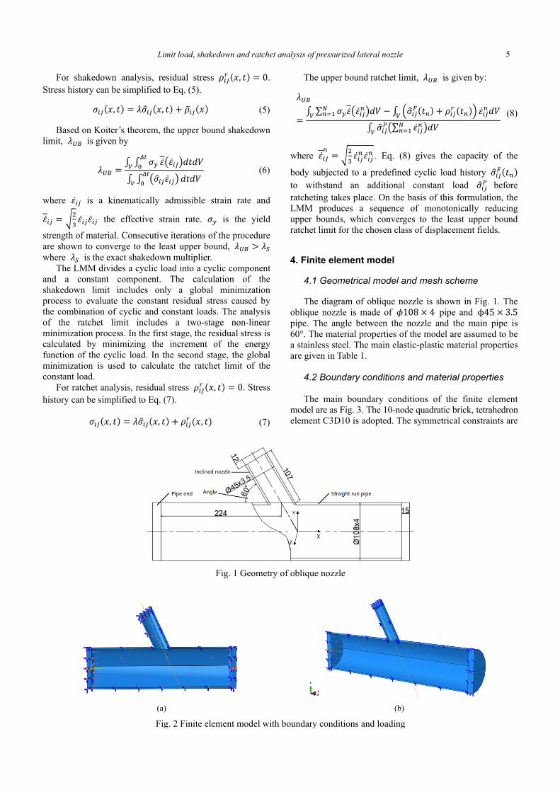
4. Finite element model 4.1 Geometrical model and mesh scheme The diagram of oblique nozzle is shown in Fig. 1. The
oblique nozzle is made of 𝜙108 × 4 pipe and ϕ45 × 3.5 pipe. The angle between the nozzle and the main pipe is 60°. The material properties of the model are assumed to be a stainless steel. The main elastic-plastic material properties are given in Table 1.
4.2 Boundary conditions and material properties The main boundary conditions of the finite element
model are as Fig. 3. The 10-node quadratic brick, tetrahedron element C3D10 is adopted. The symmetrical constraints are
Fig. 1 Geometry of oblique nozzle
(a) (b)
Fig. 2 Finite element model with boundary conditions and loading
5
Xiaohui Chen, Kunmin Zhuang, Xuanchen Zhu and Haofeng Chen
Table 1 Material properties
Elastic modulus E (Gpa)
Poisson ratio ν
Yield stress 𝑆 (Mpa)
190 0.3 320
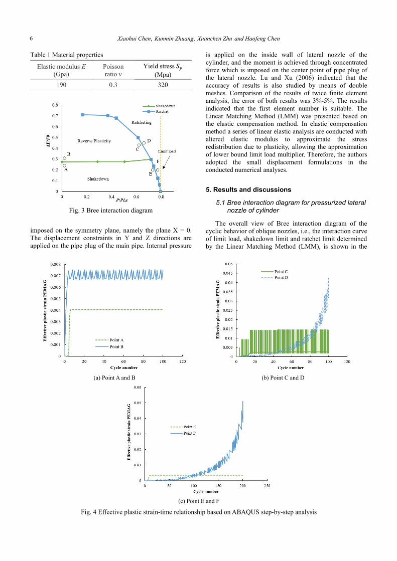
Fig. 3 Bree interaction diagram
imposed on the symmetry plane, namely the plane X = 0. The displacement constraints in Y and Z directions are applied on the pipe plug of the main pipe. Internal pressure
is applied on the inside wall of lateral nozzle of the cylinder, and the moment is achieved through concentrated force which is imposed on the center point of pipe plug of the lateral nozzle. Lu and Xu (2006) indicated that the accuracy of results is also studied by means of double meshes. Comparison of the results of twice finite element analysis, the error of both results was 3%-5%. The results indicated that the first element number is suitable. The Linear Matching Method (LMM) was presented based on the elastic compensation method. In elastic compensation method a series of linear elastic analysis are conducted with altered elastic modulus to approximate the stress redistribution due to plasticity, allowing the approximation of lower bound limit load multiplier. Therefore, the authors adopted the small displacement formulations in the conducted numerical analyses.
5. Results and discussions 5.1 Bree interaction diagram for pressurized lateral
nozzle of cylinder The overall view of Bree interaction diagram of the
cyclic behavior of oblique nozzles, i.e., the interaction curve of limit load, shakedown limit and ratchet limit determined by the Linear Matching Method (LMM), is shown in the
(a) Point A and B (b) Point C and D
(c) Point E and F
Fig. 4 Effective plastic strain-time relationship based on ABAQUS step-by-step analysis
6
Limit load, shakedown and ratchet analysis of pressurized lateral nozzle
Fig. 4. Normalized internal pressure (𝑃/𝑃 ) and normalized concentration force ( ΔF/𝐹 ) are used as abscissa and ordinate respectively. Herein, the reference concentration 𝐹 = 22000𝑁, 𝑃 is the ultimate pressure of the straight pipe with the same size as the main pipe, and determined by Eq. (9). 𝑃 = 2√3 𝜎 𝑙𝑛 𝑟𝑟 (9)
In order to verify the numerical results based on the
LMM, a step-by-step analysis based on ABAQUS was performed. Operating points of different loading combinations (points A, B, C, D, E and F in Fig. 4) are selected as reference points.
Regarding points A and B near the shakedown limit, the effective plastic strain curve is shown in Fig. 4(a). For load case A, there is no further increase in the effective plastic strain after the initial plastic strain is generated, and a stable reverse plastic behavior can be observed by the load case B. Regarding points C and D near the ratchet limit, the effective plastic strain curve is shown in Fig. 4(b). For the load case C, a stable reverse plastic behavior can be observed, and for the load case D, the ratcheting behavior of the structure can be seen. Regarding points E and F close to the ratchet limit are shown in Fig. 4(c), there is no further increase of the effective plastic strain after reaching the steady state cycle for Load Case E, indicating that the structure is in a shakedown state, while the ratcheting behavior of the structure can be clearly seen under the load condition F. In general, the above results demonstrate that the stability limits and ratcheting limits obtained using the LMM are accurate.
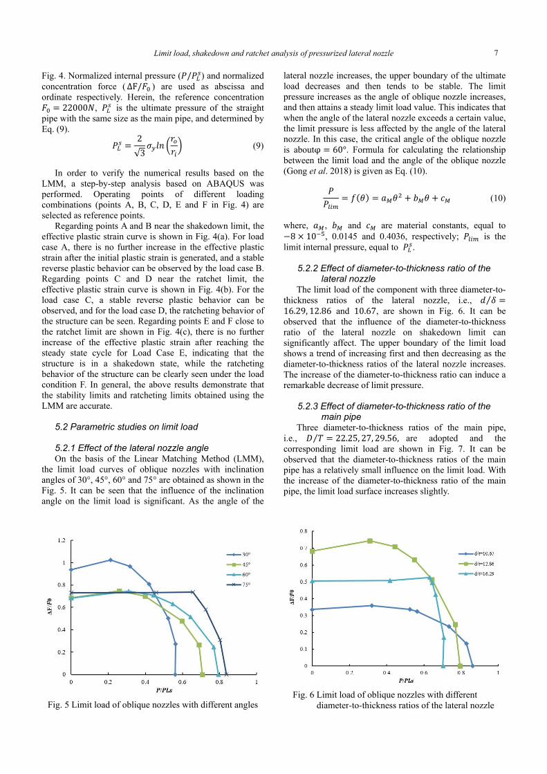
5.2 Parametric studies on limit load 5.2.1 Effect of the lateral nozzle angle On the basis of the Linear Matching Method (LMM),
the limit load curves of oblique nozzles with inclination angles of 30°, 45°, 60° and 75° are obtained as shown in the Fig. 5. It can be seen that the influence of the inclination angle on the limit load is significant. As the angle of the
Fig. 5 Limit load of oblique nozzles with different angles
lateral nozzle increases, the upper boundary of the ultimate load decreases and then tends to be stable. The limit pressure increases as the angle of oblique nozzle increases, and then attains a steady limit load value. This indicates that when the angle of the lateral nozzle exceeds a certain value, the limit pressure is less affected by the angle of the lateral nozzle. In this case, the critical angle of the oblique nozzle is aboutφ = 60°. Formula for calculating the relationship between the limit load and the angle of the oblique nozzle (Gong et al. 2018) is given as Eq. (10).
𝑃𝑃 = 𝑓(𝜃) = 𝑎 𝜃 + 𝑏 𝜃 + 𝑐 (10)
where, 𝑎 , 𝑏 and 𝑐 are material constants, equal to −8 × 10 , 0.0145 and 0.4036, respectively; 𝑃 is the limit internal pressure, equal to 𝑃 .
5.2.2 Effect of diameter-to-thickness ratio of the
lateral nozzle The limit load of the component with three diameter-to-
thickness ratios of the lateral nozzle, i.e., 𝑑 𝛿⁄ =16.29, 12.86 and 10.67, are shown in Fig. 6. It can be observed that the influence of the diameter-to-thickness ratio of the lateral nozzle on shakedown limit can significantly affect. The upper boundary of the limit load shows a trend of increasing first and then decreasing as the diameter-to-thickness ratios of the lateral nozzle increases. The increase of the diameter-to-thickness ratio can induce a remarkable decrease of limit pressure.
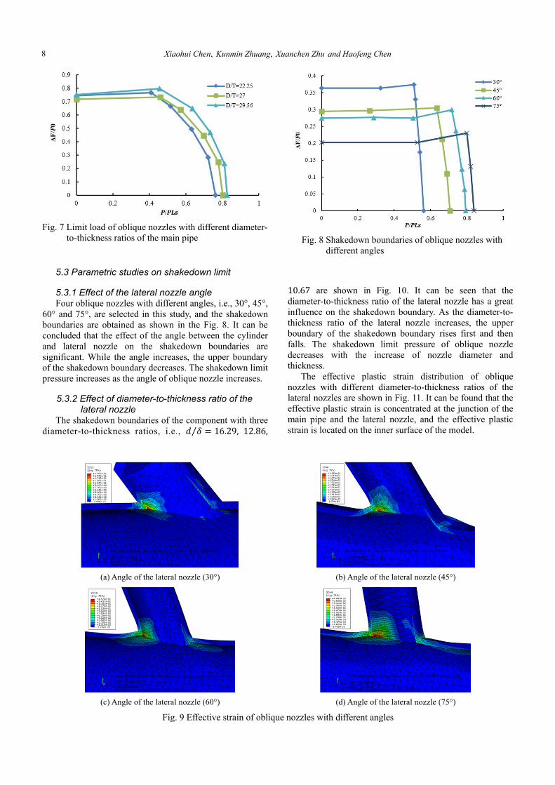
5.2.3 Effect of diameter-to-thickness ratio of the
main pipe Three diameter-to-thickness ratios of the main pipe,
i.e., 𝐷 𝑇⁄ = 22.25, 27, 29.56, are adopted and the corresponding limit load are shown in Fig. 7. It can be observed that the diameter-to-thickness ratios of the main pipe has a relatively small influence on the limit load. With the increase of the diameter-to-thickness ratio of the main pipe, the limit load surface increases slightly.
Fig. 6 Limit load of oblique nozzles with different diameter-to-thickness ratios of the lateral nozzle
7
Xiaohui Chen, Kunmin Zhuang, Xuanchen Zhu and Haofeng Chen
Fig. 7 Limit load of oblique nozzles with different diameter-to-thickness ratios of the main pipe
5.3 Parametric studies on shakedown limit 5.3.1 Effect of the lateral nozzle angle Four oblique nozzles with different angles, i.e., 30°, 45°,
60° and 75°, are selected in this study, and the shakedown boundaries are obtained as shown in the Fig. 8. It can be concluded that the effect of the angle between the cylinder and lateral nozzle on the shakedown boundaries are significant. While the angle increases, the upper boundary of the shakedown boundary decreases. The shakedown limit pressure increases as the angle of oblique nozzle increases.
5.3.2 Effect of diameter-to-thickness ratio of the
lateral nozzle The shakedown boundaries of the component with three
diameter-to-thickness ratios, i.e., 𝑑 𝛿⁄ = 16.29, 12.86,
Fig. 8 Shakedown boundaries of oblique nozzles with different angles
10.67 are shown in Fig. 10. It can be seen that the
diameter-to-thickness ratio of the lateral nozzle has a great influence on the shakedown boundary. As the diameter-to-thickness ratio of the lateral nozzle increases, the upper boundary of the shakedown boundary rises first and then falls. The shakedown limit pressure of oblique nozzle decreases with the increase of nozzle diameter and thickness.
The effective plastic strain distribution of oblique nozzles with different diameter-to-thickness ratios of the lateral nozzles are shown in Fig. 11. It can be found that the effective plastic strain is concentrated at the junction of the main pipe and the lateral nozzle, and the effective plastic strain is located on the inner surface of the model.
(a) Angle of the lateral nozzle (30°) (b) Angle of the lateral nozzle (45°)
(c) Angle of the lateral nozzle (60°) (d) Angle of the lateral nozzle (75°)
Fig. 9 Effective strain of oblique nozzles with different angles
8
Limit load, shakedown and ratchet analysis of pressurized lateral nozzle
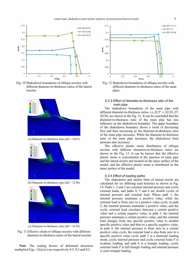
Fig. 10 Shakedown boundaries of oblique nozzles with different diameter-to-thickness ratios of the lateral nozzles
(a) Diameter-to-thickness ratio (d∕δ = 10.67)
(b) Diameter-to-thickness ratio (d∕δ = 12.86)
(c) Diameter-to-thickness ratio (d∕δ = 16.29)
Fig. 11 Effective strain of oblique nozzles with different diameter-to-thickness ratios of the lateral nozzles
Note: The scaling factors of deformed structures
multiplied Figs. 12(a)-(c) are respectively 0.5, 0.2 and 0.2.
Fig. 12 Shakedown boundaries of oblique nozzles with different diameter-to-thickness ratios of the main pipes
5.3.3 Effect of diameter-to-thickness ratio of the
main pipe The shakedown boundaries of the main pipe with
different diameter-to-thickness ratios, i.e.,𝐷 𝑇⁄ = 22.25, 27,29.56, are shown in the Fig. 12. It can be concluded that the diameter-to-thickness ratio of the main pipe has less influence on the shakedown boundary. The upper boundary of the shakedown boundary shows a trend of decreasing first and then increasing as the diameter-to-thickness ratio of the main pipe increases. While the diameter-to-thickness ratio of the main pipe increases, the shakedown limit pressure also increases.
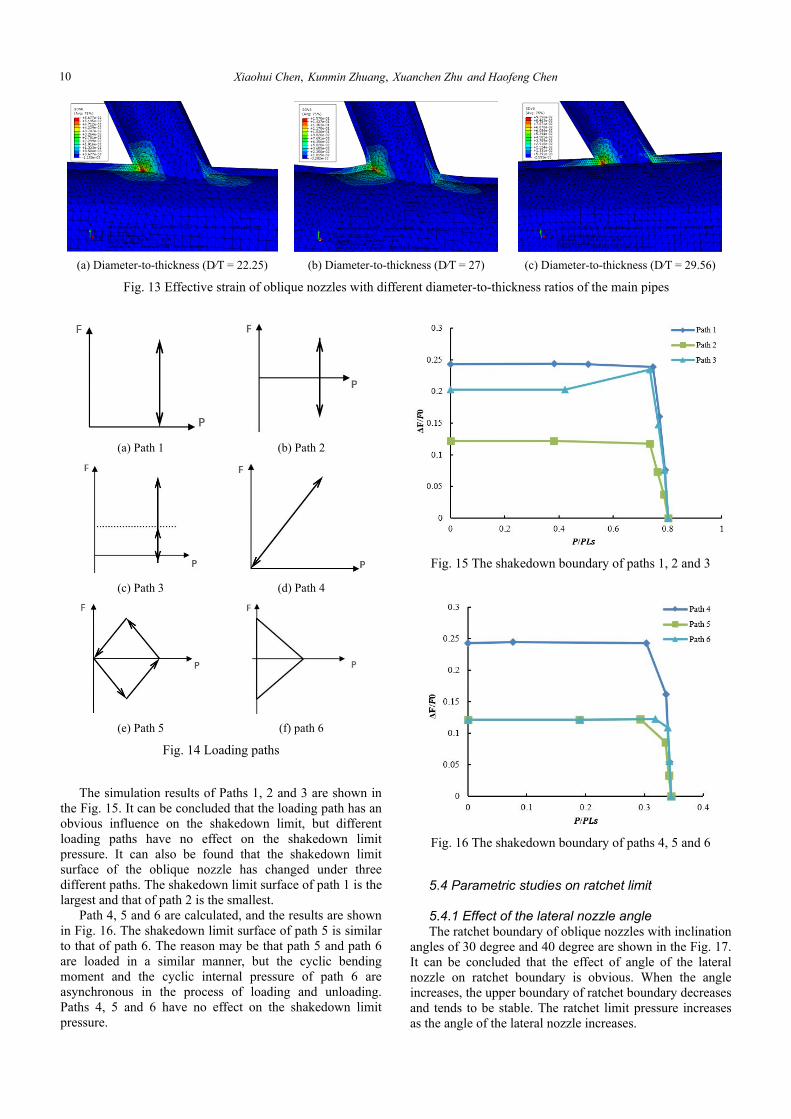
The effective plastic strain distribution of oblique nozzles with different diameters-to-thickness ratios are shown in the Fig. 13. It can be known that the effective plastic strain is concentrated at the junction of main pipe and the lateral nozzle and located on the inner surface of the model, and the effective plastic strain is distributed on the inner surface of the model.
5.3.4 Effect of loading paths The shakedown and ratchet limit of lateral nozzle are
calculated for six differing load histories as shown in Fig. 14. Paths 1, 2 and 3 are constant internal pressure and cyclic external loads, and paths 4, 5 and 6 are double cycles of internal pressure and external load. Where path 1, the internal pressure maintains a positive value, while the external load is from zero to a positive value cycle; in path 2, the internal pressure maintains a positive value, and the cyclic external load circulates between a certain positive value and a certain negative value; in path 3, the internal pressure maintains a certain positive value, and the external load changes from one specific positive value to another specific positive value and then to a specific negative value, in path 4, the internal pressure is from zero to a certain positive value cycle, the external load is also from zero to a specific positive value cycle; path 5 is a diamond loading mode, cyclic internal pressure and cyclic external loads F is in-phase loading; and path 6 is a triangle loading, cyclic external loads F is full triangle loading and internal pressure is semi-triangle loading.
9
Xiaohui Chen, Kunmin Zhuang, Xuanchen Zhu and Haofeng Chen
(a) Path 1 (b) Path 2
(c) Path 3 (d) Path 4
(e) Path 5 (f) path 6
Fig. 14 Loading paths The simulation results of Paths 1, 2 and 3 are shown in
the Fig. 15. It can be concluded that the loading path has an obvious influence on the shakedown limit, but different loading paths have no effect on the shakedown limit pressure. It can also be found that the shakedown limit surface of the oblique nozzle has changed under three different paths. The shakedown limit surface of path 1 is the largest and that of path 2 is the smallest.
Path 4, 5 and 6 are calculated, and the results are shown in Fig. 16. The shakedown limit surface of path 5 is similar to that of path 6. The reason may be that path 5 and path 6 are loaded in a similar manner, but the cyclic bending moment and the cyclic internal pressure of path 6 are asynchronous in the process of loading and unloading. Paths 4, 5 and 6 have no effect on the shakedown limit pressure.
Fig. 15 The shakedown boundary of paths 1, 2 and 3
Fig. 16 The shakedown boundary of paths 4, 5 and 6 5.4 Parametric studies on ratchet limit 5.4.1 Effect of the lateral nozzle angle The ratchet boundary of oblique nozzles with inclination
angles of 30 degree and 40 degree are shown in the Fig. 17. It can be concluded that the effect of angle of the lateral nozzle on ratchet boundary is obvious. When the angle increases, the upper boundary of ratchet boundary decreases and tends to be stable. The ratchet limit pressure increases as the angle of the lateral nozzle increases.
(a) Diameter-to-thickness (D∕T = 22.25) (b) Diameter-to-thickness (D∕T = 27) (c) Diameter-to-thickness (D∕T = 29.56)
Fig. 13 Effective strain of oblique nozzles with different diameter-to-thickness ratios of the main pipes
10
Limit load, shakedown and ratchet analysis of pressurized lateral nozzle
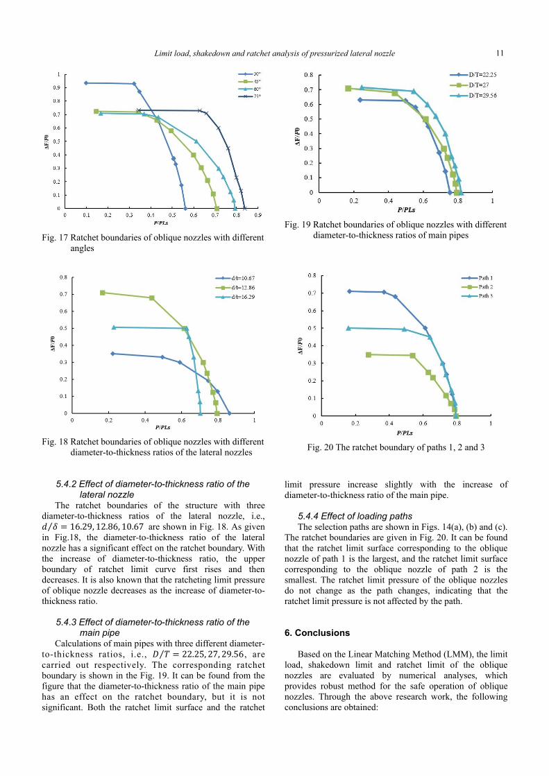
Fig. 17 Ratchet boundaries of oblique nozzles with different angles
Fig. 18 Ratchet boundaries of oblique nozzles with different diameter-to-thickness ratios of the lateral nozzles
5.4.2 Effect of diameter-to-thickness ratio of the
lateral nozzle The ratchet boundaries of the structure with three
diameter-to-thickness ratios of the lateral nozzle, i.e., 𝑑 𝛿⁄ = 16.29, 12.86, 10.67 are shown in Fig. 18. As given in Fig.18, the diameter-to-thickness ratio of the lateral nozzle has a significant effect on the ratchet boundary. With the increase of diameter-to-thickness ratio, the upper boundary of ratchet limit curve first rises and then decreases. It is also known that the ratcheting limit pressure of oblique nozzle decreases as the increase of diameter-to-thickness ratio.
5.4.3 Effect of diameter-to-thickness ratio of the
main pipe Calculations of main pipes with three different diameter-
to-thickness ratios, i.e., 𝐷 𝑇⁄ = 22.25, 27, 29.56, are carried out respectively. The corresponding ratchet boundary is shown in the Fig. 19. It can be found from the figure that the diameter-to-thickness ratio of the main pipe has an effect on the ratchet boundary, but it is not significant. Both the ratchet limit surface and the ratchet
Fig. 19 Ratchet boundaries of oblique nozzles with different diameter-to-thickness ratios of main pipes
Fig. 20 The ratchet boundary of paths 1, 2 and 3
limit pressure increase slightly with the increase of diameter-to-thickness ratio of the main pipe.
5.4.4 Effect of loading paths The selection paths are shown in Figs. 14(a), (b) and (c).
The ratchet boundaries are given in Fig. 20. It can be found that the ratchet limit surface corresponding to the oblique nozzle of path 1 is the largest, and the ratchet limit surface corresponding to the oblique nozzle of path 2 is the smallest. The ratchet limit pressure of the oblique nozzles do not change as the path changes, indicating that the ratchet limit pressure is not affected by the path.
6. Conclusions Based on the Linear Matching Method (LMM), the limit
load, shakedown limit and ratchet limit of the oblique nozzles are evaluated by numerical analyses, which provides robust method for the safe operation of oblique nozzles. Through the above research work, the following conclusions are obtained:
11
Xiaohui Chen, Kunmin Zhuang, Xuanchen Zhu and Haofeng Chen
(1) According to LMM, the Bree interaction diagram of the cyclic behavior of oblique nozzles, i.e., the interaction curve of limit load, shakedown limit and ratchet limit is calculated. Moreover, through the step-by-step analysis of ABAQUS, the curve of plastic strain and time is obtained, which validates the reliability of the linear matching method.
(2) The angle and diameter-to-thickness ratio of nozzle have greater influence on the limit load. The diameter-to-thickness ratio of the main pipe has little effect on the limit pressure.
(3) For the shakedown limit of oblique nozzles, the angle and the diameter to thickness ratio of the nozzles have a great influence on the shakedown limit. While the diameter to thickness ratio of main pipe has less influence on the shakedown limit.
(4) Ratcheting limit is greatly affected by angle and diameter-to-thickness ratio of nozzle, while the diameter-to-thickness ratio of main pipe has little effect on ratcheting limit.
Acknowledgments This work was partly supported by the Natural Science
Foundation of Hebei Province of China (No. E2018501022), China Postdoctoral Science Foundation Funded Project (No. 2017M610171) and Fundamental Research Funds for the Central Universities (No. N182304009).
References ABAQUS (2013), User’s Manual, Version 6.12-3. Abdalla, H.F., Megahed, M.M. and Younan, M.Y. (2006),
“Determination of shakedown limit load for a 90 degree pipe bend using a simplified technique”, J. Press. Vessel Technol., 128, 618-624. https://doi.org/10.1115/1.2349575
Abou-Hanna, J. and McGreevy, T.E. (2011), “A simplified ratcheting limit method based on limit analysis using modified yield surface”, Int. J. Pres. Ves. Pip., 88, 11-8. https://doi.org/10.1016/j.ijpvp.2010.12.001
Adibi-Asl, R. and Reinhardt, W. (2009), “Shakedown/Ratcheting Boundary Determination Using Iterative Linear Elastic Schemes”, In: Proceedings of the ASME Pressure Vessels and Piping Conference, Prague, Czech Republic, pp. 109-119.
Adibi-Asl, R. and Reinhardt, W. (2011a), “Non-cyclic shakedown/ratcheting boundary determination e Part 1: Analytical approach”, Int. J. Press. Ves. Pip., 88, 311-320. https://doi.org/10.1016/j.ijpvp.2011.06.006
Adibi-Asl, R. and Reinhardt, W. (2011b), “Non-cyclic shakedown/ratcheting boundary determination - Part 2: Numerical implementation”, Int. J. Press. Ves.Pip., 88, 321-329. https://doi.org/10.1016/j.ijpvp.2011.06.007
Ainsworth, R.A. (editor) (2003), “R5: Assessment Procedure for the High Temperature Response of Structures”, Issue 3, British Energy Generation Ltd.
Barbera, D., Chen, H.F., Liu, Y.H. and Xuan, F.Z. (2017), “Recent developments of the linear matching method framework for structural integrity assessment”, J. Press. Vessel Technol., 139(5), 051101. https://doi.org/10.1115/1.4036919
Bree, J. (1989), “Plastic deformation of a closed tube due to interaction of pressure stresses and cyclic thermal stresses”, Int.
J. Mech. Sci., 31(11-12), 865-892. https://doi.org/10.1016/0020-7403(89)90030-1
Chen, H.F. and Ponter, A.R.S. (2005a), “Integrity assessment of a 3D tubeplate using the linear matching method. Part 1. Shakedown, reverse plasticity and ratchetting”, Int. J. Pres. Ves. Pip., 82(2), 85-94. https://doi.org/10.1016/j.ijpvp.2004.07.015
Chen, H.F. and Ponter, A.R.S. (2005b), “Integrity assessment of a 3D tubeplate using the linear matching method. Part 2: Creep rela ation and reverse plasticity”, Int. J. Pres. Ves. Pip., 82(2), 95-104. https://doi.org/10.1016/j.ijpvp.2004.07.016
Chen, L., Liu, Y., Yang, P., Cen, Z. (2008), “Limit analysis of structures containing flaws based on a modified elastic compensation method”, Eur. J. of Mech. / A Solids, 27, 195-209. https://doi.org/10.1016/j.euromechsol.2007.05.010
Chen, H.F., Chen, W.H., Li, T.B. and Ure, J. (2012), “On shakedown, ratchet and limit analyses of defective pipeline”, J. Press. Vessel Technol., 134, 011202/1-8. https://doi.org/10.1115/1.4004801
Chen, H.F., Ure, J.M. and Tipping, D. (2013), “Calculation of a lower bound ratchet limit part 1 – Theory, numerical implementation and verification”, Eur. J. of Mech. / A Solids, 37, 361-368. https://doi.org/10.1016/j.euromechsol.2012.04.001
Chen, H.F., Ure, J. and Tipping, D.J. (2014), “Integrated structural analysis tool using the Linear Matching Method part 2–Application and verification”, Int. J. Pres. Ves. Pip.,1 20-121, 152-161. https://doi.org/10.1016/j.ijpvp.2014.05.005
Chen, X.H., Gao, B.J. and Wang, X.G. (2016), “Evaluation of limit load analysis for pressure vessels: Part I – Linear and Nonlinear methods”, Steel Compos. Struct., Int. J., 22(6), 1391-1415. https://doi.org/10.12989/scs.2016.22.6.1391
Chen, X.H., Gao, B.J. and Wang, X.G. (2017a), “Evaluation of limit load analysis for pressure vessels: Part II - Robust methods”, Steel Compos. Struct., Int. J., 23(1), 131-142. https://doi.org/10.12989/scs.2017.23.1.131
Chen, X.H., Wang, X.G. and Chen, X. (2017b), “Effect of temperature on ratcheting behavior of pressurized 90° elbow pipe under force controlled cyclic loading”, Smart Struct. Syst., Int. J., 19(5), 473-485. https://doi.org/10.12989/sss.2017.19.5.473
Engelhardt, M. (2000), “Computational modelling of shakedown”, University of Leicester, Thesis.
Gokhfeld, D.A. (1980), “Limit analysis of structures at thermal cycling”, Sijthoff & Noordhoff.
Gong, J.G., Niu, T.Y., Chen, H.F. and Xuan, F.Z. (2018), “Shakedown analysis of pressure pipeline with an oblique nozzle at elevated temperatures using the linear matching method”, Int. J. Press. Ves. Pip., 159, 55-66. https://doi.org/10.1016/j.ijpvp.2017.11.008
Koiter, W.T. (1960), “General theorems for elastic plastic solids”, In: Progress in Solid Mechanics, Vol. 1, J.N. Sneddon and R. Hill, eds., North Holland, Amsterdam, pp. 167-221.
Lu, M.W. and Xu, H. (2006), “Discussion on some important problems of design by analysis”, In: Pressure Vessles, 23, 15-19. [In Chinese]
Mackenzie, D., Boyle, J.T. and Hamilton, R. (1993), “The elastic compensation method for limit and shakedown analysis: a review”, J. Strain Anal., 35, 171-188. https://doi.org/10.1243/0309324001514332
Mackenzie, D., Boyle, J.T. and Hamilton, R. (2000), “The elastic compensation method for limit and shakedown analysis: a review”, J. Strain Anal. Eng. Des., 35(3), 171-188. https://doi.org/10.1243/0309324001514332
Makulsawatudom, P., Mackenzie, D. and Hamilton, R. (2004), “Shakedown behaviour of thick cylindrical vessels with cross holes”, Proceedings of the Institution of Mechanical Engineers, Part E: Journal of Process Mechanical Engineering, 218(3), 133-141. https://doi.org/10.1243/0954408041323430
Marriott, D.L. (1988), “Evaluation of deformation or load control
12
Limit load, shakedown and ratchet analysis of pressurized lateral nozzle
of stresses under inelastic conditions using the elastic finite element stress analysis”, Proceedings of the ASME Pressure Vessels and Piping Conference, Pittsburgh, PA, USA, 136, 3-9.
Martin, M. and Rice, D. (2009), “A hybrid procedure for ratchet boundary prediction”, In: ASME 2009 Pressure Vessels and Piping Conference, Prague, Czech Republic, pp. 81-88.
Martin, M., Rawson, L. and Rice, D. (2010), “A hierarchical finite element framework for the assessment of pressure vessels to the ASME III code”, In: ASME 2010 Pressure Vessels and Piping Conference, 1, 125-135.
Martin, M., Watson, C. and Wright, K. (2011), “Review of ASME III Code Case for the Application of Finite Element Based Limit Load Analysis”, In: ASME 2011 Pressure Vessels and Piping Conference, 1, 513-518.
Melan, E. (1936), “TheoriestatischunbestimmterSystemeaus ideal-plastichemBaustoff”, Sitzungsber. d. Akad. d. Wiss., Wien 2A(145), 195-218.
Muscat, M. and Mackenzie, D. (2003), “Elastic-shakedown analysis of axisymmetric nozzles”, J. Press. Vessel Technol., 125(4), 365-370. https://doi.org/10.1115/1.1613301
Muscat, M., Hamilton, R. and Boyle, J.T. (2002), “Shakedown analysis for complex loading using superposition”, J. Strain Anal. Eng. Des., 37(5), 399-412. https://doi.org/10.1243/030932402760203865
Muscat, M., Mackenzie, D. and Hamilton, R. (2003), “Evaluating shakedown under proportional loading by non-linear static analysis”, Com. Struct., 81(17), 1727-1737. https://doi.org/10.1016/S0045-7949(03)00181-0
Nadarajah, C., Mackenzie, D. and Boyle, J.T. (1993), “A method of estimating limit loads by iterative elastic analysis. II-Nozzle sphere intersections with internal pressure and radial load”, Int. J. Pres. Ves. Pip., 53, 97-119. https://doi.org/10.1016/0308-0161(93)90106-4
Nguyen-Tajan, T.M.L., Pommier, B., Maitournam, H., Houari, M., Verger, L., Du, Z.Z. and Snyman, M. (2003), “Determination of the stabilized response of a structure undergoing cyclic thermal-mechanical loads by a direct cyclic method”, In: Abaqus Users' Conference Proceedings.
Oh, C.-S., Kim, Y.-J. and Park, C.-Y. (2008), “Shakedown limit loads for elbows under internal pressure and cyclic in-plane bending”, Int. J. Pres. Ves. Pip., 85(6), 394-405. https://doi.org/10.1016/j.ijpvp.2007.11.009
Ponter, A.R.S. and Carter, K.F. (1996), “Limit state solutions, based upon linear elastic solutions with a spatially varying elastic modulus”, Comput. Method. Appl. Mech. Eng., 140, 237-258. https://doi.org/10.1016/S0045-7825(96)01104-8
Ponter, A.R.S. and Carter, K.F. (1997), “Limit state solutions, based upon linear elastic solutions with a spatially varying elastic modulus”, Comput. Meth. Appl. Mech. Eng., 140, 237-258. https://doi.org/10.1016/S0045-7825(96)01104-8
Ponter, A.R.S. and Chen, H. (2001), “A minimum theorem for cyclic load in excess of shakedown, with application to the evaluation of a ratchet limit”, Euro. J. Mech. A/Solids, 20, 539-553. https://doi.org/10.1016/S0997-7538(01)01161-5
Ponter, A.R.S. and Engelhardt, M. (2000), “Shakedown limits for a general yield condition: implementation and application for a Von Mises yield condition”, Eur. J. Mech. A/Solids, 19(3), 423-445. https://doi.org/10.1016/S0997-7538(00)00171-6
Ponter, A.R.S., Fuschi, P. and Engelhardt, M. (2000), “Limit analysis for a general class of yield conditions”, Eur. J. Mech. A/Solids, 19, 401-421. https://doi.org/10.1016/S0997-7538(00)00170-4
Reinhardt, W. (2008), “A noncyclic method for plastic shakedown analysis”, J. Press. Vessel Technol., 130(3), 031209. https://doi.org/10.1115/1.2937760
Seshadri, R. and Fernando, C.P.D. (1991), “Limit loads of mechanical components and structures using the Gloss R-node
method”, Proceedings of the ASME Pressure Vessels and Piping Conference, San Diego, CA, USA, 210, 125-134.
Shi, J., Mackenzie, D. and Boyle, J.T. (1993), “A method of estimating limit loads by iterative elastic analysis. III-Torispherical heads under internal pressure”, Int. J. Pres. Ves. Pip., 53, 121-142. https://doi.org/10.1016/0308-0161(93)90107-5
Tipping, D.J. (2007), “The Linear Matching Method: A Guide to the ABAQUS User Subroutines”, E/REP/BBGB/0017/GEN/07, British Energy Generation.
Ure, J.M., Chen, H.F., Chen, W., Li, T., Tipping, D.J. and Mackenzie, D. (2011), “A direct method for the evaluation of lower and upper bound ratchet limits”, Proceedings of the 11th International Conference on Mechanical Behaviour of Materials, June, Lake Como, Italy.
Ure, J.M., Chen, H.F. and Tipping, D. (2013), “Calculation of a lower bound ratchet limit part 2 : Application to a pipe intersection and dissimilar material join”, Eur. J. Mech. - A/Solids, 37, 369-378. https://doi.org/10.1016/j.euromechsol.2012.04.002
Ure, J., Chen, H.F. and Tipping, D.J. (2014), “Integrated structural analysis tool using the linear matching method part 1 – Software development”, Int. J. Pres. Ves.Pip., 120-121, 141-151. https://doi.org/10.1016/j.ijpvp.2014.05.004
Yang, P., Liu, Y., Ohtake, H., Yuan, H. and Cen, Z. (2005), “Limit analysis based on a modified elastic compensation method for nozzel-to-cylinder junctions”, Int. J. Pres. Ves.Pip., 82, 770-776. https://doi.org/10.1016/j.ijpvp.2005.06.005
Zheng, X.T., Peng, H.Y., Yu, J.Y., Wang, W., Lin, W. and Xu, J.M. (2017), “Analytical ratchet limit for pressurized pipeline under cyclic nonproportional loadings”, J. Pipeline Syst. Pract., 8(3), 04017002. https://doi.org/10.1061/(ASCE)PS.1949-1204.0000260
CC 1
13
Xiaohui Chen, Kunmin Zhuang, Xuanchen Zhu and Haofeng Chen
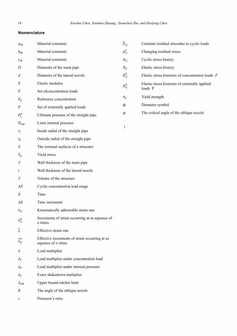
Nomenclature 𝑎 Material constants 𝑏 Material constants 𝑐 Material constants
D Diameter of the main pipe
d Diameter of the lateral nozzle
E Elastic modulus
F Set ofconcentration loads 𝐹 Reference concentration
P Set of externally applied loads 𝑃 Ultimate pressure of the straight pipe 𝑃 Limit internal pressure 𝑟 Inside radial of the straight pipe 𝑟 Outside radial of the straight pipe
S The external surfaces of a strucutre 𝑆 Yield stress
T Wall thickness of the main pipe
t Wall thickness of the lateral nozzle
V Volume of the structure
Δ𝐹 Cyclic concentration load range 𝛿 Time
Δ𝛿 Time increment
Kinematically admissible strain rate
Increments of strain occurring at as equence of n times
Effective strain rate
Effective increments of strain occurring at as equence of n times 𝜆 Load multiplier 𝜆 Load multiplier under concentration load 𝜆 Load multiplier under internal pressure 𝜆 Exact shakedown multiplier 𝜆 Upper bound ratchet limit 𝜃 The angle of the oblique nozzle
ν Poiosson’s ratio
𝜌 Constant residual stressdue to cyclic loads 𝜌 Changing residual stress 𝜎 Cyclic stress history 𝜎 Elastic stress history 𝜎 Elastic stress histories of concentration loads 𝐹𝜎
Elastic stress histories of externally applied loads P 𝜎 Yield strength 𝜙 Diameter symbol 𝜑 The critical angle of the oblique nozzle
1
14
Related Documents