LIGHTNIN ® LabMaster™ Mixer Operational Guide BK223116 Rev. H

Welcome message from author
This document is posted to help you gain knowledge. Please leave a comment to let me know what you think about it! Share it to your friends and learn new things together.
Transcript
LIGHTNIN®
LabMaster™ Mixer Operational Guide BK223116 Rev. H

1
Information in this user manual is subject to change without notice. © 2004 LIGHTNIN MIXERS All rights reserved. Printed in U.S.A. Reproduction in any manner whatsoever without the permission of LIGHTNIN is strictly forbidden. Trademarks LIGHTNIN is a registered trademark of LIGHTNIN. LabMaster is a trademark of LIGHTNIN.
2
1 REGULATORY NOTICES .......................................................................................................................... 6
2 LIGHTNIN LABMASTER MIXER INSTALLATION AND OPERATION ......................................... 10
3 ON/OFF SWITCH ....................................................................................................................................... 12
4 KEYPAD DEFINITIONS ........................................................................................................................... 12
5 RUN MODE ................................................................................................................................................. 12
5.1 FAULTS ...................................................................................................................................................... 13
6 SET MODE .................................................................................................................................................. 13
7 DIAGNOSTIC MODE ................................................................................................................................ 14
7.1 POWER ON TEST ........................................................................................................................................ 14 7.2 ENTERING DIAGNOSTIC MODE ................................................................................................................... 14 7.3 ACCEPTANCE TEST .................................................................................................................................... 14 7.4 POWER MEASUREMENT CALIBRATION....................................................................................................... 15 7.5 TEMPERATURE: CALIBRATION OF EXTERNAL PROBE ............................................................................... 15
8 ACCESSORIES ........................................................................................................................................... 16
8.1 STAINLESS STEEL CHUCK RETROFIT AND SHAFT INSTALLATION INSTRUCTIONS ...................................... 17
9 LABMASTER FEATURES AND SPECIFICATIONS............................................................................ 18
10 SALES OFFICES......................................................................................................................................... 19
11 WARRANTY................................................................................................................................................ 20
TABLES TABLE 1 LABMASTER KEYPAD................................................................................................................................ 12 TABLE 2 RUN MODE DISPLAY OPTIONS................................................................................................................... 12 TABLE 3 RUN MODE - KEYPAD DEFINITIONS ...................................................................................................... 12, 13 TABLE 4 FAULTS ...................................................................................................................................................... 13 TABLE 5 SET ITEMS.................................................................................................................................................. 13 TABLE 6 SET MODE - KEYPAD DEFINITIONS ............................................................................................................ 14 TABLE 7 POWER ON TEST ERROR ............................................................................................................................ 14 FIGURES FIGURE 1 - GENERAL ARRANGEMENT DRAWING (L1U10 & L5U10) ........................................................................ 8 FIGURE 2 - GENERAL ARRANGEMENT DRAWING (L1U10F & L5U10F) .................................................................... 9 FIGURE 3 - INITIAL INSTALLATION ........................................................................................................................... 10 FIGURE 4 - IMPELLERS ............................................................................................................................................. 11

3
WARNING NOTES
• DO NOT START MIXER BEFORE VERIFYING VOLTAGE CONFIGURATION.
• THE LabMaster MIXER IS SUPPLIED CONFIGURED FOR THE DESTINATION LINE VOLTAGE REQUESTED (115 OR 230 VOLTS). THE 230 VOLT EUROPEAN MODELS ARE 115 VOLT MIXERS SUPPLIED WITH A STEP DOWN TRANSFORMER. THE STEP DOWN TRANSFORMER CONVERTS 230 VOLT, 50HZ DOWN TO THE PROPER VOLTAGE FOR THE SUPPLIED MIXER. FAILURE TO USE THE SUPPLIED TRANSFORMER WITH THE SUPPLIED MIXER, WILL DAMAGE THE MIXER AND VOID ANY WARRANTIES. CHECK WHETHER THE VOLTAGE INDICATED ON THE REAR OF THE UNIT MATCHES THE AVAILABLE LINE VOLTAGE.
• DO NOT ATTEMPT TO SERVICE OR REPOSITION THE MIXER WHILE SHAFT/IMPELLER IS ROTATING.
• DO NOT ALLOW LOOSE CLOTHING OR PARTS OF THE BODY TO COME NEAR THE ROTATING MIXER SHAFT.
• BEFORE SERVICING THE MIXER, ALWAYS TURN THE POWER OFF USING THE ON/OFF SWITCH ON THE FRONT OF THE UNIT. UNPLUG AND REMOVE THE POWER CORD TO AVOID TANGLING OR BREAKING.
• DO NOT ATTEMPT TO OPEN OR REPAIR THE MIXER. THERE IS NO USER SERVICEABLE COMPONENTS IN THE MIXER. REMOVAL OR DESTRUCTION OF THE HOUSING VOIDS ANY WARRANTY, EXPLICIT OR IMPLIED. CONSULT THE FACTORY FOR QUALIFIED TECHNICAL SERVICE ASSISTANCE.
• USE ONLY HIGH QUALITY LIGHTNIN MIXER SHAFTS AND HEAVY-DUTY RING STANDS. USE OF NON-LIGHTNIN MIXER SHAFTS OR RING STAND COULD RESULT IN INJURY TO THE OPERATOR OR DAMAGE TO THE LabMaster MIXER.
• ALWAYS KEEP THE LabMaster MIXER SHAFT CLEAN. ACCUMULATION OF FOREIGN MATTER ON THE SHAFT COULD INCREASE THE POTENTIAL FOR PERSONAL INJURY.
• CARE MUST BE TAKEN WHEN SETTING THE OPERATING SPEEDS OF YOUR MIXER. OPERATION AT EXCESSIVE SPEEDS IN SMALL MIXING VESSELS COULD CAUSE CONTENTS TO SPLASH ON PERSONNEL IN THE AREA.
• AT CERTAIN SPEEDS, THE MIXER SHAFT MAY EXPERIENCE EXCESSIVE VIBRATION. THIS IS DUE TO NATURAL FREQUENCY OSCILLATIONS. OPERATING IN THIS MODE IS DANGEROUS. ALTER THE SPEED HIGHER OR LOWER TO ELIMINATE THE VIBRATION.

4
AVERTISSEMENT
• VERIFIER LA TENSION DU COURANT AVANT DE METTRE L'AGITATEUR EN MARCHE.
• LE SELECTEUR DE TENSION DU LabMaster A ETE POSITIONNE EN USINE POUR LA TENSION DU PAYS DESTINATAIRE DEMANDEE (115 OU 230 V). LES MODELES EUROPEENS 230 VOLT SONT DES AGITATEURS 115 VOLT FOURNIS AVEC UN TRANSFORMATEUR ABAISSEUR DE TENSION. CE TRANSFORMATEUR CONVERTIT LA TENSION DE 230 VOLT, 50Hz EN LA TENSION CORRESPONDANT A L’AGITATEUR FOURNI. LA NON-UTILISATION DU TRANSFORMATEUR FOURNI ENDOMMAGERA L’AGITATEUR ET ANNULERA LA GARANTIE. VERIFIER SI LA TENSION INDIQUEE, A L’ARRIERE DE L’APPAREIL, CORRESPOND BIEN A LA TENSION LOCALE DU SECTEUR.
• NE PAS DEPLACER L'AGITATEUR LORSQUE L'ARBRE PORTE HELICE TOURNE.
• EVITER TOUT CONTACT AVEC LES PARTIES TOURNANTES.
• AVANT TOUTE INTERVENTION SUR L’AGITATEUR, METTRE L’INTERRUPTEUR MARCHE-ARRET, SITUE EN FACADE DE L’APPAREIL, EN POSITION ARRET. DEBRANCHER ET RETIRER LE CORDON D’ALIMENTATION POUR EVITER DE L’EMMELER OU DE LE CASSER..
• EN CAS DE PANNE, NOUS CONSULTER. NE PAS ESSAYER D'OUVRIR OU DE REPARER L'AGITATEUR SOI MEME. L'ENTRETIEN DES COMPOSANTS INTERNES DEMANDE UN PERSONNEL ET UN OUTILLAGE SPECIALISES. TOUTE INTERVENTION PAR UNE PERSONNE NON HABILITEE ANNULERAIT LAGARANTIE.
• N'UTILISER QUE DES ACCESSOIRES FOURNIS PAR LIGHTNIN. L'UTILISATION D'ARBRES ET DE SUPPORTS D'AUTRE PROVENANCE PEUT ETRE. LA CAUSE D'ACCIDENTS CORPORELS OU MATERIELS.
• NETTOYER REGULIEREMENT L'ARBRE PORTE HELICE L'ACCUMULATION DE PRODUIT SUR L'ARBRE PEUT ETRE LA CAUSE D'ACCIDENTS CORPORELS OU MATERIELS.
• NE PAS FAIRE TOURNER L'AGITATEUR A DES VITESSES EXCESSIVES DANS DE PETITS VOLUMES AFIN D'EVITER DES PROJECTIONS DE PRODUIT.
• A CERTAINES VITESSES, L’AGITATEUR PEUT SUBIR DES VIBRATIONS EXCESSIVES. CELLES-CI SONT DUES AUX FREQUENCES NATURELLES D’OSCILLATION (LES HARMONIQUES). L’UTILISATION DE L’AGITATEUR A CES FREQUENCES EST DANGEREUX ET DOMMAGEABLE. POUR ELIMINER CES VIBRATIONS, IL FAUT AUGMENTER OU REDUIRE LA VITESSE

5
WARNUNGSHINWEISE: • DEN LabMaster NICHT ANSTELLEN BEVOR DIE SPANNUNGSEINSTELLUNG (Voltzah)
ÜBERPRÜFT WURDE.
• DER LabMaster WURDE FÜR DEN BETRIEB MIT DER VOM KUNDEN GEWÜNSCHTEN NETZSPANNUNG GELIEFERT (115 ODER 230 V). DIE EUROPÄISCHEN MODELLE FÜR 230V ANTRIEB SIND MIT EINEM TRANSFORMATOR FÜR UMSETZUNG DER NETZSPANNUNG VON 230V, 50Hz AUF 115V, 60Hz GELIEFERT. DIE UMGESETZTE SPANNUNG VON 115V IST RICHTIG FÜR DEN GELIEFERTEN LabMaster UND NICHT GEBRAUCH DES TRANSFORMATORS BESCHÄDIGT DEN LabMaster UND LÖSCHT ALLE PRODUKT GARANTIEN. BITTE PRÜFEN SIE, OB DIE AUF DER RÜCKSEITE DER ANTRIEBSEINHEIT ANGEGEBENE SPANNUNG MIT DER VERFÜGBAREN NETZSPANNUNG ÜBEREINSTIMMT.
• NICHT VERSUCHEN, DEN LabMaster ZU WARTEN ODER UMZUSTELLEN, WÄHREND SICH DIE WELLE/RÜHRORGAN DREHEN.
• LOCKERE KLEIDUNGSSTÜCKE ODER KÖRPERTEILE VON DER ROTIERENDEN WELLE UNBEDINGT FERNHALTEN.
• BEVOR SIE SERVICEARBEITEN AM RÜHRER VORNEHMEN SCHALTEN SIE GRUNDSÄTZLICH DEN RÜHRER MITTELS EIN-/AUSSCHALTER AN DER VORDERSEITE AUS UND ZIEHEN SIE DAS NETZKABEL, UM EINE EVENTUELLE VERWICKLUNG ODER KABELBRUCH ZU VERMEIDEN.
• NICHT VERSUCHEN, DEN LabMaster ZU ÖFFNEN ODER ZU REPARIEREN. ES GIBT KEINE AUSWECHSELBAREN BESTANDTEILE IM LabMaster. DAS BESEITIGEN ODER DIE ZERSTÖRUNG VON GEHÄUSEDICHTUNGEN HEBEN JEGLICHE GARANTIEN AUF, EGAL OB DIESE DEUTLICH ODER INBEGRIFFEN SIND. FRAGEN SIE BEIM HERSTELLER NACH QUALIFIZIERTER TECHNISCHER SERVICEUNTERSTUTZUNG.
• NUR HOCHQUALITÄTS RÜHRERWELLEN UND STABILE RINGSTATIVE VON LIGHTNIN BENUTZEN. DER GEBRAUCH VON RÜHRERWELLEN UND RINGSTATIVE EINER ANDEREN MARKE KÖNNEN ZU VERLETZUNGEN DES BEDIENERS ODER ZU SCHÄDEN AN DEM LabMaster SI MIXER FÜHREN.
• DIE LabMaster RÜHRERWELLE IMMER SAUBER HALTEN. SCHMUTZANHÄUFUNGEN AUF DER WELLE KÖNNEN DIE VERLETZUNGSGEFAHR DES BEDIENUNGSPERSONALS ERHÖHEN.
• DIE GESCHWINDIGKEITEN DES LabMasters MÜSSEN VORSICHTIG EINGESTELLT WERDEN. BEI MISCHUNGEN MIT HOHEN GESCHWINDIGKEITEN IN KLEINEN MISCHBEHÄLTERN KÖNNEN FLÜSSIGKEITEN AUF PERSONAL IN UNMITTELBARER NÄHE GESPRITZT WERDEN.
• BEI BESTIMMTEN DREHZAHLEN KÖNNEN AN DER RÜHRERWELLE GRÖßERE SCHWINGUNGEN, AUFGRUND DER EIGENSCHWINGUNGSZAHL DES RÜHRWERKES AUFTRETEN. EIN BETRIEB IN DIESEM BEREICH IST ZU VERMEIDEN UND ES SOLLTEN DREHZAHLEN ÜBER ODER UNTER DIESEM BEREICH GEWÄHLT WERDEN, UM DIESE SCHWINGUNGEN ZU VERMEIDEN.

6
1 Regulatory Notices This equipment is designed to be safe at least under the following conditions: Indoor use, altitude up to 2000m, temperature 5°C to 40°C, maximum relative humidity 80% for temperatures up to 31°C decreasing linearly to 50% relative humidity at 40%, mains supply voltage fluctuations not to exceed +/-10% of the nominal voltage, transient overvoltages according to Installation Category 11 and Pollution degree 2 in accordance with IEC 664. FCC Notice (U.S. Only) All models of Lightnin Labmaster series mixers are classified by the FCC as Class A digital devices and as such the following FCC notices apply: WARNING: Changes or modifications to this unit not expressly approved by
the party responsible for compliance could void the user’s authority to operate this equipment.
NOTE: This equipment has been tested and found to comply with the limits for a
Class A digital device, pursuant to Part 15 of the FCC rules. These limits are designed to provide reasonable protection against harmful interference when the equipment is operated in a commercial environment. This equipment generates, uses and can radiate radio frequency energy and, if not installed and used in accordance with the manufacturer’s instruction manual, may cause harmful interference to radio communications. Operation of this equipment in a residential area is likely to cause harmful interference in which case the user will be required to correct the interference at his own expense.
Shielded cables must be used with this unit to ensure compliance with the Class A FCC limits. IC Notice (Canada Only) All models of Lightnin Labmaster series mixer are classified by Industry Canada (IC) ICES-003, Issue 2 as Class A digital devices. Devices that are tested and comply with Class A FCC Specifications also comply with the Canadian Specification following the harmonization of Canadian Regulation with existing FCC regulations effective January 31, 1989. As such the following notices apply: This digital apparatus does not exceed the Class A limits for radio noise emissions from digital apparatus set out in the Radio Interference Regulations of the Canadian Department of Communications. Le present appareil numerique n’emet pas de bruits radioelectriques depassant les limites applicables aux appareils numeriques de la class A prescrites dans le Reglement sur le brouillage radioelectrique edicte par le ministere Des Communications du Canada.

7
CE Notice Marking by the CE symbol indicates compliance of all models of the LIGHTNIN Labmaster series mixers to the Machinery Directive, Low Voltage Directive and EMC Directive of the European Community. The LIGHTNIN LabMaster mixers meet technical standard EN55022 - Limits and Methods of Measurements of Radio Interference Characteristics of Information Technology Equipment (ITE) as a Class A device. As such the following notices apply: WARNING: This is a Class A product. In a domestic environment this product
may cause radio interference in which case the user may be required to take adequate measures.
VCCI Notice (Japan Only) All models of LIGHTNIN Labmaster series mixers are classified by the Voluntary Control Council for Interference (VCCI) as Class 1 information technology equipment (ITE) and as such the following VCCI notices apply: Class 1 Notice This equipment complies with the limits for a Class 1 digital device (devices used in commercial and/or industrial environments) and conforms to the standards for information technology equipment (ITE) that are set by the Voluntary Control Council for Interference for preventing radio frequency interference in commercial and/or industrial areas. Consequently, when used in a residential area or in an area adjacent to a residential area, this equipment may cause radio interference with radio and television receivers or other communications equipment. To ensure that such radio interference does not occur, it is important to install and use this equipment in accordance with the manufacturer’s instruction manual.

8
CERTIFIED
LIGHTNIN
ISO 9001
CERTIFIED BY:
5.002.003.12--L5U10
NOTES:(1) TOTAL MIXER WEIGHT: 18 LBS. OPTIONAL RING STAND WEIGHT: 14 LBS.(2) POWER CORD WITH GROUNDED PLUG. LENGTH APPROX. 6 FEET(3) ALL DIMENSIONS ARE IN INCHES.(4) THE SHAFT LENGTH OF THE L1U10 MODEL CAN BE ADJUSTED BY PASSING THE SHAFT THROUGH THE UNIT.(5) MODEL L5U10 ONLY
L1U10L5U10
MODEL
1/101/10
H.P.
7575
WATTS
1:13.66:1
SPEEDREDUCTION
CDATE: 2001
20 - 55050 - 1800
OUTPUTR.P.M.
R100DIA. (IN.)
LabMaster IMPELLERS INCLUDED
L1U10
MODELA310
DIA. (IN.)
4.00
A100DIA. (IN.)
2.72 2.00
(5)
7.25
9.63
4.6
4.50
1.31
A320DIA. (IN.)
---
4.88
1.14
1.3 MAXIMUM
2.00
5.00
ALL EQUIPMENT DESIGN AND APPLICATION DATA SHOWN HEREINAND RELATED KNOW-HOW IS CONFIDENTIAL AND THE PROPERTY
NO USE OR DISCLOSURE THEREOF MAY BE MADE WITHOUT
LABORATORY MIXER
DRAWING NO. DS-P-134E(BOOK)
OUR WRITTEN PERMISSION.
OF THE LIGHTNIN GROUP OF COMPANIES.
DIMENSION DRAWINGMIXERS AND AERATORS
VARIABLE SPEEDL1U10 & L5U10
LabMaster
R
COMPLIANT
20.98
3.03
0
8
5
2
LABMASTER
SET
RESET
STOP
RUN
4
7
1
6
9
3 9.88
1.5
6.00
11.38
STAINLESS STEEL CHUCK AVAILABLE ATEXTRA COST
2.60
OPTIONAL(5)
1.44
Figure 1 - General Arrangement Drawing

9
STAINLESS STEEL CHUCK AVAILABLE ATEXTRA COST
CERTIFIED
LIGHTNIN
ISO 9001
CERTIFIED BY:
5.002.003.12--L5U10F
NOTES:
(2) TOTAL MIXER WEIGHT: 18 LBS. OPTIONAL RING STAND WEIGHT: 14 LBS.(3) POWER CORD WITH GROUNDED PLUG. LENGTH APPROX. 6 FEET(4) ALL DIMENSIONS ARE IN INCHES.(5) THE SHAFT LENGTH OF THE L1U10F MODEL CAN BE ADJUSTED BY PASSING THE SHAFT THROUGH THE UNIT.(6) MODEL L5U10F ONLY
L1U10FL5U10F
MODEL
1/101/10
H.P.
7575
WATTS
1:13.66:1
SPEEDREDUCTION
CDATE: 2001
20 - 55050 - 1800
OUTPUTR.P.M.
R100DIA. (IN.)
LabMaster IMPELLERS INCLUDED
L1U10F
MODELA310
DIA. (IN.)
4.00
A100DIA. (IN.)
2.72 2.00
(6)
7.25
9.63
4.6
4.50
1.31
A320DIA. (IN.)
---
4.88
(6)
1.14
1.3 MAXIMUM
2.00
5.00
ALL EQUIPMENT DESIGN AND APPLICATION DATA SHOWN HEREINAND RELATED KNOW-HOW IS CONFIDENTIAL AND THE PROPERTY
NO USE OR DISCLOSURE THEREOF MAY BE MADE WITHOUT
WITH COMPUTER CONTROLLER
DRAWING NO. DS-P-135D(BOOK)
OUR WRITTEN PERMISSION.
OF THE LIGHTNIN GROUP OF COMPANIES.
DIMENSION DRAWINGMIXERS AND AERATORS
VARIABLE SPEED LAB MIXERL1U10F & L5U10F
LabMaster
R
COMPLIANT
2.60
20.98
3.03
0
8
5
2
LABMASTER
SET
RESET
STOP
RUN
4
7
1
6
9
3 9.88
1.5
6.00
11.38
OPTIONAL
1.44
SEEDETAIL "A"
RS-232 PORT PERMITS FEEDING DATA TO LAB COMPUTER
DETAIL "A"
RJ JACK
TEMPERATURE PROBEREADOUT IN ° F OR C
(1) VARIABLE SPEED RANGE: 50 - 1800 RPM
Figure 2 - General Arrangement Drawing
10
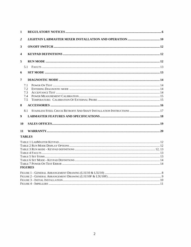
2 LIGHTNIN LabMaster Mixer Installation and Operation
2.1. Mount the mixer on the LIGHTNIN ring stand (or tank rim). Insert the mixer shaft into the shaft chuck and tighten. If shaft run-out is excessive, re-chuck the shaft. Orient the shaft/impeller in the approximate location illustrated in the plan and elevation views.
Figure 3 - Initial Installation
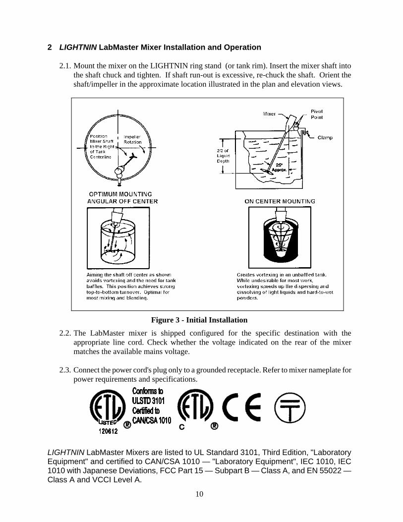
2.2. The LabMaster mixer is shipped configured for the specific destination with the appropriate line cord. Check whether the voltage indicated on the rear of the mixer matches the available mains voltage.
2.3. Connect the power cord's plug only to a grounded receptacle. Refer to mixer nameplate for
power requirements and specifications. LIGHTNIN LabMaster Mixers are listed to UL Standard 3101, Third Edition, "Laboratory Equipment" and certified to CAN/CSA 1010 — "Laboratory Equipment", IEC 1010, IEC 1010 with Japanese Deviations, FCC Part 15 — Subpart B — Class A, and EN 55022 — Class A and VCCI Level A.
11
2.4. Set the speed and start the mixer, adjusting the speed to achieve desired mixer action as outlined in Section 5 and Section 6.
CAUTION
Rotating Parts. Can cause minor injury.
Do not touch rotating parts.
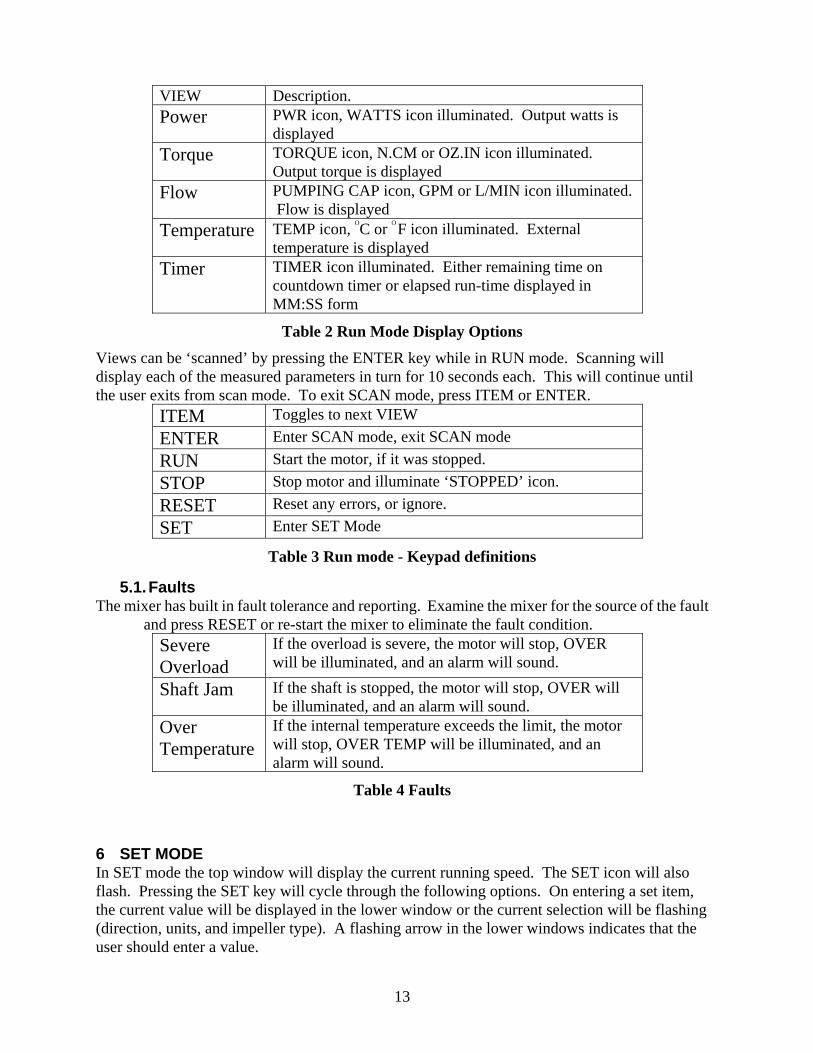
2.5. For models provided with additional styles and diameters of impellers when changes are made:
a. Install A310, A315, A320, and A100 impellers with the convex face of the blades facing up. Tighten set screw securely.
b. Install R100 impeller with the hub body portion of the impeller facing up. Tighten set screw securely.
c. A200 impeller can be oriented either way on shaft.
Figure 4 - Impellers
2.6. Each time a different impeller is installed, the mixer must be reconfigured to match the style and diameter of the impeller being used. See Section 6 for instructions.
2.7. Impeller Adjustment: (DISCONNECT POWER CORD PRIOR TO ADJUSTING) a. L1U10 and L1U10F models have the thru-shaft feature. Remove the blanking
grommet from the top of the housing. Impellers can be adjusted by raising or lowering the shaft. Loosen the chuck with chuck key, adjust the shaft to suit depth or desired mixing action. Retighten the chuck with chuck key. Re-install the grommet if thru-shaft feature is not in use.
b. On L5U10 and L5U10F series mixers without the thru shaft feature, adjust the impeller to the desired position on the shaft and secure with set screw.
2.8. Do not allow the mixer housing to become immersed or subjected to excessive splash or spray. The unit should be cleaned using a cloth moistened with warm water only – do not use detergent or solvent based cleaners. Should it be necessary to clean the Liquid Crystal Display (LCD), switch off the mixer and use lens cleaning tissue which should be lightly moistened with lens cleaning fluid or warm water.

12
2.9. There are no internal user serviceable components in the mixer. Do not attempt to open or dismantle mixers or warranty will be voided. Consult your nearest LIGHTNIN representative for qualified technical service assistance.
2.10. Two anti-surge fuses protect the mixer. It is recommended that the fuses be replaced in pairs, if necessary. Use only approved fuses. To change the fuses:
Disconnect power to unit. Located fuses above and below the AC power inlet
Using a flat screwdriver blade, insert into the slot on the fuse holder, exert a little downward pressure and rotate counter-clockwise and the fuse holder will reverse out of the housing. Replace new fuses and re-install holder.
Approved fuses: UL/CSA 3.15A 250v Anti-surge BUSSMAN type S506 IEC 2.5A 250v Anti-surge BUSSMAN type S506
2.11. REPOSITIONING DURING THE MIXING CYCLE: Sometimes more than one kind of mixing action is needed. For example, you may first
need to dissolve light powders, so start with the mixer centered to create a vortex that quickly disperses them into the batch. Stop the mixer and disconnect the power cord. Then, to maintain a uniform suspension or to blend in other fluids, reposition the mixer to angular off-center.
3 ON/OFF Switch The LabMaster is activated by depressing the ON/OFF button located on the front of the unit. When the LabMaster is ON, the LCD will be illuminated. 4 Keypad Definitions
Run 1 2 3 Stop 4 5 6 Reset 7 8 9 Set Item 0 Enter
Table 1 LabMaster Keypad
5 RUN MODE In RUN mode, the top window will always display the current running speed. The DIRECTION icon and the IMPELLER STYLE icon will also indicate the direction and the impeller style. The lower window will display the information selected by the ITEM key. Pressing the ITEM key will cycle through the following displays in the lower window.
13
VIEW Description. Power PWR icon, WATTS icon illuminated. Output watts is
displayed Torque TORQUE icon, N.CM or OZ.IN icon illuminated.
Output torque is displayed Flow PUMPING CAP icon, GPM or L/MIN icon illuminated.
Flow is displayed Temperature TEMP icon, OC or OF icon illuminated. External
temperature is displayed Timer TIMER icon illuminated. Either remaining time on
countdown timer or elapsed run-time displayed in MM:SS form
Table 2 Run Mode Display Options
Views can be ‘scanned’ by pressing the ENTER key while in RUN mode. Scanning will display each of the measured parameters in turn for 10 seconds each. This will continue until the user exits from scan mode. To exit SCAN mode, press ITEM or ENTER.
ITEM Toggles to next VIEW ENTER Enter SCAN mode, exit SCAN mode RUN Start the motor, if it was stopped. STOP Stop motor and illuminate ‘STOPPED’ icon. RESET Reset any errors, or ignore. SET Enter SET Mode
Table 3 Run mode - Keypad definitions
5.1. Faults The mixer has built in fault tolerance and reporting. Examine the mixer for the source of the fault
and press RESET or re-start the mixer to eliminate the fault condition. Severe Overload
If the overload is severe, the motor will stop, OVER will be illuminated, and an alarm will sound.
Shaft Jam If the shaft is stopped, the motor will stop, OVER will be illuminated, and an alarm will sound.
Over Temperature
If the internal temperature exceeds the limit, the motor will stop, OVER TEMP will be illuminated, and an alarm will sound.
Table 4 Faults
6 SET MODE In SET mode the top window will display the current running speed. The SET icon will also flash. Pressing the SET key will cycle through the following options. On entering a set item, the current value will be displayed in the lower window or the current selection will be flashing (direction, units, and impeller type). A flashing arrow in the lower windows indicates that the user should enter a value.

14
SET ITEM Description. Speed SPEED icon flashes. Current set speed displayed in
digits. Use 0-9 to enter new set speed. Direction DIRECTION icon (either clockwise or counter-
clockwise) illuminated. Use ITEM to toggle between directions. (Note: this set item will be skipped if the motor is running.)
Units MM or IN icon flashing. Use ITEM to toggle between units. Select MM for SI units (mm, L/min, n.cm, OC) or IN for English units (in, GPM, in.oz. or OF).
Timer TIMER icon flashes. Use 0-9 to enter the value for countdown timer in MM:SS form. With the countdown timer set, the unit will run until the timer expires. When the timer reaches 00:00, the unit will stop. If entry is 00:00, the unit will run continuously.
Impeller Style
IMP icon flashes. Use ITEM for select the impeller type. Upon selecting an impeller, the diameter is set to the default value. If you do not wish to use the default diameter, enter diameter in AAAA for millimetres or BBB.B for inches and tenths of inches. (Note: If USER is selected, the user will be prompted by an arrow to enter impeller diameter first, Press Enter, then enter Flow Constant and Press Enter again. Flow Constant is entered in hundredths. Example: XX67 is 0.67)
Table 5 Set Items After input or selection, there are three options. ENTER accepts setting and returns to RUN mode, SET accepts setting and cycle to next set item, RESET does not change setting and returns to RUN mode.
ITEM Toggles to next selection/icon (direction, units, or impeller icons)
ENTER Accept entered or selected setting and return to RUN mode
RUN Start the motor, if it was stopped. STOP Stop motor and illuminate ‘STOPPED’ icon. RESET Ignore inputs for the current set item and return to RUN
mode SET Toggle to the next set item, accepting any data or
selections made in the previous set item
Table 6 Set Mode - Keypad Definitions 7 DIAGNOSTIC MODE Diagnostics are used to test the unit on start-up and to calibrate power and temperature measurement.
15
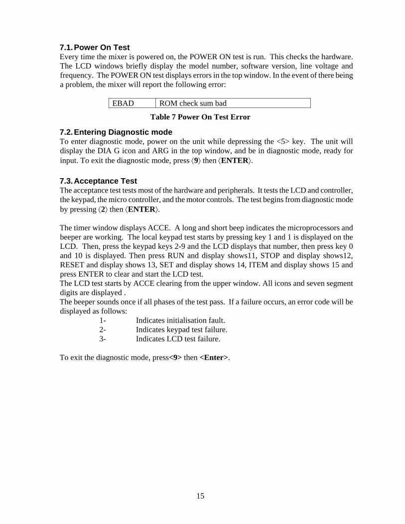
7.1. Power On Test Every time the mixer is powered on, the POWER ON test is run. This checks the hardware. The LCD windows briefly display the model number, software version, line voltage and frequency. The POWER ON test displays errors in the top window. In the event of there being a problem, the mixer will report the following error:
EBAD ROM check sum bad
Table 7 Power On Test Error
7.2. Entering Diagnostic mode To enter diagnostic mode, power on the unit while depressing the <5> key. The unit will display the DIA G icon and ARG in the top window, and be in diagnostic mode, ready for input. To exit the diagnostic mode, press ⟨9⟩ then ⟨ENTER⟩.
7.3. Acceptance Test The acceptance test tests most of the hardware and peripherals. It tests the LCD and controller, the keypad, the micro controller, and the motor controls. The test begins from diagnostic mode by pressing ⟨2⟩ then ⟨ENTER⟩.
The timer window displays ACCE. A long and short beep indicates the microprocessors and beeper are working. The local keypad test starts by pressing key 1 and 1 is displayed on the LCD. Then, press the keypad keys 2-9 and the LCD displays that number, then press key 0 and 10 is displayed. Then press RUN and display shows11, STOP and display shows12, RESET and display shows 13, SET and display shows 14, ITEM and display shows 15 and press ENTER to clear and start the LCD test. The LCD test starts by ACCE clearing from the upper window. All icons and seven segment digits are displayed . The beeper sounds once if all phases of the test pass. If a failure occurs, an error code will be displayed as follows:
1- Indicates initialisation fault. 2- Indicates keypad test failure. 3- Indicates LCD test failure.
To exit the diagnostic mode, press<9> then <Enter>.
16
7.4. Power Measurement Calibration
To ensure the most accurate results, you must calibrate the mixer with this simple program prior to any series of mixing experiments.
NOTE: Start this procedure with the mixer power on. The shaft and impeller must be removed and set the mixer to its minimum speed value, press enter and switch the mixer OFF.
In diagnostic mode, press ⟨6⟩ and then ⟨ENTER⟩. The mixer runs the power calibration program. It starts the mixer and runs the motor to maximum speed, incrementing by 5 % each time. At each speed, it calibrates the measurement. This procedure will take up to 3½ minutes to complete.
The calibration can be terminated at any time by pressing ⟨RESET⟩. To restart the calibration, press ⟨6⟩ then ⟨ENTER⟩.
Motor losses are temperature dependent. It is recommended that the calibration program be run prior to any series of mixing experiments. Frequent calibration ensures the most accurate results.
NOTE: If the calibration process fails, the mixer beeps repeatedly until ⟨RESET⟩ is pressed.
The program will exit to RUN mode.
7.5. Temperature: Calibration Of External Probe NOTE: This sequence is performed with the mixer motor stopped.
Enter diagnostic mode. In diagnostic mode, press ⟨7⟩ and then ⟨ENTER⟩. Place connected temperature probe in substance at known temperature and compare with temperature reading displayed on the LCD. To correct the mixer reading, press key 1 to increment reading upwards by one degree per actuation for degrees C and two degrees per actuation for degrees F. To decrease the LCD reading, press key 2. To exit the diagnostic mode, press<9> then <Enter>.

17
8 ACCESSORIES
LIGHTNIN LabMaster Mixer
Model
Power
Watts, HP
Thru Shaft
RS-232
Temp Probe
Output RPM
Torque
NcM, Oz.in
Catalog #. (115VAC)
Catalog # (230VAC)
L1U10F
75, 1/10
STD
STD
STD
50-1800
48, 68
836277PSP
836284PSP
L1U10
75, 1/10
STD
N/A
N/A
50-1800
48, 68
836275PSP
836282PSP
L5U10F
75, 1/10
N/A
STD
STD
20-550
159,225
836278PSP
836285PSP
L5U10
75, 1/10
N/A
N/A
N/A
20-550
159,225
836276PSP
836283PSP
Heavy-Duty Ring Stand
16 mm (.63″) Rod, 610 mm (24.0″)high Heavy Base Cat. #829453PSP 316 Stainless Steel Shafts
Model
Shaft Dia.*
Shaft
Length
Catalog Number
L1U10
9.5 mm (.38″)
610 mm (24.0″)
143727
L5U10
9.5 mm (.38″)
610 mm (24.0″)
143727
* 9.5 mm (.38″) dia. shaft turned down to 8 mm (.31″) dia. at impeller end
Impeller Ordering Information
Style
Bore Dia.
Dia.
Catalog Number
A310 8 mm (.31″) 64 mm (2.5″) 808955PSP A310 8 mm (.31″) 64 mm (2.5″)
ring guard 808999PSP
A310 8 mm (.31″) 86 mm (3.4″) 809410PSP A310 8 mm (.31″) 96 mm (3.8″) 809411PSP A310 8 mm (.31″) 114 mm (4.5″) 809412PSP A100 8 mm (.31″) 25 mm (1.0″) 800570PSP A100 8 mm (.31″) 38 mm (1.5″) 800569PSP A100 8 mm (.31″) 51 mm (2.0″) 800568PSP A100 8 mm (.31″) 51 mm (2.0″)
folding 800578PSP
A100 8 mm (.31″) 51 mm (2.0″) ring guard
800580PSP A100 8 mm (.31″) 69 mm (2.7″) 809417PSP A100 8 mm (.31″) 79 mm (3.1″) 809418PSP A200 8 mm (.31″) 51 mm (2.0″) 829448PSP A315 8 mm (.31″) 76 mm (3.0″) 869468PSP A315 8 mm (.31″) 102 mm (4.0″) 869470PSP A315 8 mm (.31″) 127 mm (5.0″) 869472PSP A320 8 mm (.31″) 76 mm (3.0″) 869513PSP A320 8 mm (.31″) 102 mm (4.0″) 869515PSP A320 8 mm (.31″) 127 mm (5.0″) 869381PSP A410 ‘A’ 8 mm (.31″) 100 mm (3.9″) 218837PSP R500 8 mm (.31″) 51 mm (2.0″) 869579PSP R500 8 mm (.31″) 76 mm (3.0″) 869580PSP R100 8 mm (.31″) 38 mm (1.5″) 809414PSP R100 8 mm (.31″) 51 mm (2.0″) 809415PSP Paddle 8 mm (.31″) 51 mm (2.0″) 800579PSP
311

18
8.1 LABMASTER STAINLESS STEEL CHUCKRETROFIT AND
SHAFT INSTALLATION INSTRUCTIONS SECTION 1 - STAINLESS STEEL RETROFIT - MODELS L1U10, L1U10F, L5U10, L1U10F
WARNING: DISCONNECT MOTOR POWER CORD OR OTHERWISE LOCK-OUT POWER SUPPLY BEFORE SERVICING THIS MIXER. EYE PROTECTION MUST BE WORN. 1.1 Place a hex key or screw driver (Maximum diameter 0.175”, Minimum length 4”) into the small hole in the back of
the LabMaster housing. The tool must pass through the holes in the mixer drive shaft and into a cup inside the case to prevent; bending the tool, possible damage to the inside of the mixer, and the drive shaft from turning.
1.2 Using a strap wrench or locking pliers, remove the steel chuck. 1.3 Apply Loctite 222MS to the drive shaft threads. 1.4 Thread the stainless steel chuck onto the drive shaft and tighten. 1.5 Remove the hex key or screw driver.
SECTION 2 - STAINLESS STEEL RETROFIT - MODELS L1U03, L1U08, L1U08F, L5U08, L5U08F
WARNING: DISCONNECT MOTOR POWER CORD OR OTHERWISE LOCK-OUT POWER SUPPLY BEFORE SERVICING THIS MIXER. EYE PROTECTION MUST BE WORN. 2.1 Restrain the mixer drive shaft. 2.2 Using a strap wrench or locking pliers, remove the steel chuck. 2.3 Apply Loctite 222MS to the drive shaft threads. 2.4 Thread the stainless steel chuck onto the drive shaft and tighten. 2.5 Remove the mixer drive shaft restraint.
SECTION 3 - SHAFT INSTALLATION WARNING: DISCONNECT MOTOR POWER CORD OR OTHERWISE LOCK-OUT POWER SUPPLY BEFORE SERVICING THIS MIXER. EYE PROTECTION MUST BE WORN. 3.1 To install the mixer shaft, back off (DO NOT REMOVE) the chuck screw, see below.
Note: Chuck screw removal will cause the chuck grip to fall out. 3.2 Insert the mixer shaft into the chuck bore. Tighten the chuck screw. The chuck grip will press against the mixer
shaft holding it in place. DO NOT IMPACT THE WRENCH OR USE AN EXTENSION 3.3 To remove the mixer shaft back off the chuck screw 1/4 turn. DO NOT REMOVE the chuck screw.
CHUCK GRIP
CHUCK SCREW
STAINLESS STEEL CHUCK
©©
REVISION2002
DATE 11-6-02
REVISED PAGE 1 OF 1
INST. NO. IT-5238LIGHTNINMIXERS AND AERATORS
® © LIGHTNIN

19
9 LabMaster FEATURES RS–232 port permits recording data and remote computer operation.
Speed Display: 50–1800 rpm for direct drive; 20–550 for gear drive
Process Watts and Torque Display
Timer Display (counts up or down).
Flow readout (L/min or GPM) for seven different impellers
Standard Temperature Probe –Readouts in oF or oC.
Thru-Shaft Design for infinitely variable impeller position.
Calibration for process watts and temperature measurement.
User-defined acceleration/deceleration rates with optional software package (default set by factory).
Overload indicator and alarm
Chemically Resistant Housing
Universal Mounting Clamp (use with ring stand or tank rim).
Tactile and audible feedback, sealed membrane control panel
Fuse protection for severe overload
Minor overload protection via automatic speed level control
75 Watts (1/10 hp), 115 or 230 volts, 50/60 Hz
SPECIFICATIONS MODEL L1U10(F) 115V L1U10(F) 230V L5U10(F) 115V L5U10(F) 230V
INPUT VOLTAGE +/- 15% 115 VOLTS 230 VOLTS 115 VOLTS 230 VOLTS INPUT CURRENT AMPS AC 2 AMPS 2 AMPS 2 AMPS 2 AMPS
INPUT FREQUENCY Hz +/-5% 50 / 60 50 / 60 50 / 60 50 / 60 SPEED RANGE RPM 50 TO 1800 50 TO 1800 20 TO 550 20 TO 550 SPEED REGULATION +/- 5 RPM PLUS (+)
+/- 0 .5% OF SET SPEED +/- 5 RPM PLUS (+)
+/- 0 .5% OF SET SPEED +/- 5 RPM PLUS (+)
+/- 0 .5% OF SET SPEED +/- 5 RPM PLUS (+)
+/- 0 .5% OF SET SPEED TIMER ACCURACY +/- 2% OF SET TIME +/- 2% OF SET TIME +/- 2% OF SET TIME +/- 2% OF SET TIME
MAX TORQUE 68 IN-OZ 68 IN-OZ 225 IN-OZ 225 IN-OZ POWER PEAK AT MAX RPM FOR 30 MINUTES 75 WATTS 75 WATTS 75 WATTS 75 WATTS
CONTINUOUS POWER AT MAX RPM 40 WATTS 40 WATTS 40 WATTS 40 WATTS
CURRENT AT RATED TORQUE +/- 15% 1.2 AMPS 1.2 AMPS 1.2 AMPS 1.2 AMPS
CURRENT LIMIT +/- 15% 1.4 AMPS 1.4 AMPS 1.4 AMPS 1.4 AMPS CURRENT TRIP +/- 15% 1.7 AMPS 1.7 AMPS 1.7 AMPS 1.7 AMPS
FUSES 5 X 20 mm FAST ACTING 250V 3.15 A 250T3.15 2.5 A 250T2.5 3.15 A 250T3.15 2.5 A 250T2.5
INTERNAL TEMP TRIP POINT +/- 5% DEG. C 60 DEG. C 60 DEG. C 58 DEG. C 58 DEG. C
DERATING ABOVE 25 DEG. C 1. 5 WATTS PER DEG. C 1. 5 WATTS PER DEG. C 1. 5 WATTS PER DEG. C 1. 5 WATTS PER DEG. C

20
10 SALES OFFICES LIGHTNIN LabMaster PRECISION MIXING INSTRUMENTS In addition to our LabMaster solid-state, microprocessor-controlled mixers, LIGHTNIN offers a complete line of fluid mixers for the laboratory and process industries. LIGHTNIN can make lab work easier and more precise. Just call us. Tell us what your lab needs to stir or mix, and we'll have your unit delivered. In fact, call anytime you have a question about mixing. You'll get answers drawn from over 50 years of mixing experience for applications large and small. LIGHTNIN mixers are at work around the clock doing hundreds of thousands of specific jobs for labs and production processes around the world. For immediate details on LIGHTNIN mixers or a demonstration, call LIGHTNIN or the LIGHTNIN Toll-free in the US 1-888 MIX BEST (1-888-649-2378)
United Kingdom
Brixworth +44 (0) 1604-88-0751
USA Rochester, NY +1 (585) 436-5550
Australia Homebush Bay +61 (2) 9763-4901
China Shanghai +86 (21) 5495-5616
Singapore Jurong +65-6264-4366

21
11 WARRANTY The LIGHTNIN mixer warranty: In the case of a failure of any mixer supplied, which is the result of defective material or workmanship, we will repair or replace it to your satisfaction, or refund the purchase price. This warranty extends to twelve (12) months after first installation of the mixer or for eighteen (18) months after its shipment from our factory, whichever period is shorter. REPLACEMENT PARTS, INSTRUCTION MANUALS, ELECTRONIC AND
MIXING APPLICATION TECHNICAL SUPPORT SPX PROCESS EQUIPMENT LIGHTNIN P.O. Box 31370 Rochester, New York 14603 Tel. (585) 436-5550 Fax (585) 436-5589 LIGHTNIN sales engineers are located in principal cities around the world.
Related Documents