Lighting Computer Graphics

Lighting Computer Graphics. Outline Lighting Lighting models Ambient Diffuse Specular Surface Rendering Methods.
Dec 24, 2015
Welcome message from author
This document is posted to help you gain knowledge. Please leave a comment to let me know what you think about it! Share it to your friends and learn new things together.
Transcript

Lighting
Computer Graphics

Outline
•Lighting•Lighting models
•Ambient•Diffuse•Specular
•Surface Rendering Methods

What we know
• We already know how to render the world from a viewpoint.

“Lighting”
• Two components:– Lighting Model or
Shading Model - how we calculate the intensity at a point on the surface
– Surface Rendering Method - How we calculate the intensity at each pixel

Jargon
• Illumination - the transport of light from a source to a point via direct and indirect paths
• Lighting - computing the luminous intensity for a specified 3D point, given a viewpoint
• Shading - assigning colors to pixels
• Illumination Models:
– Empirical - approximations to observed light properties
– Physically based - applying physics properties of light and its interactions with matter

The lighting problem…
• What are we trying to solve?
• Global illumination – the transport of light within a scene.
• What factors play a part in how an object is “lit”?
• Let’s examine different items here…

Two components
• Light Source Properties– Color (Wavelength(s) of light)– Shape– Direction
• Object Properties– Material– Geometry– Absorption
8 Angel: Interactive Computer Graphics 5E © Addison-Wesley 2009
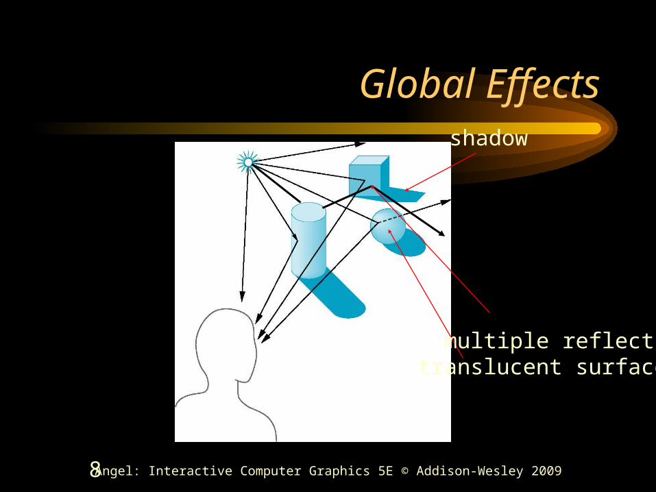
Global Effects
translucent surface
shadow
multiple reflection

9 Angel: Interactive Computer Graphics 5E © Addison-Wesley 2009
Local vs Global Rendering
• Correct shading requires a global calculation involving all objects and light sources– Incompatible with pipeline model which shades
each polygon independently (local rendering)
• However, in computer graphics, especially real time graphics, we are happy if things “look right”– Exist many techniques for approximating global
effects
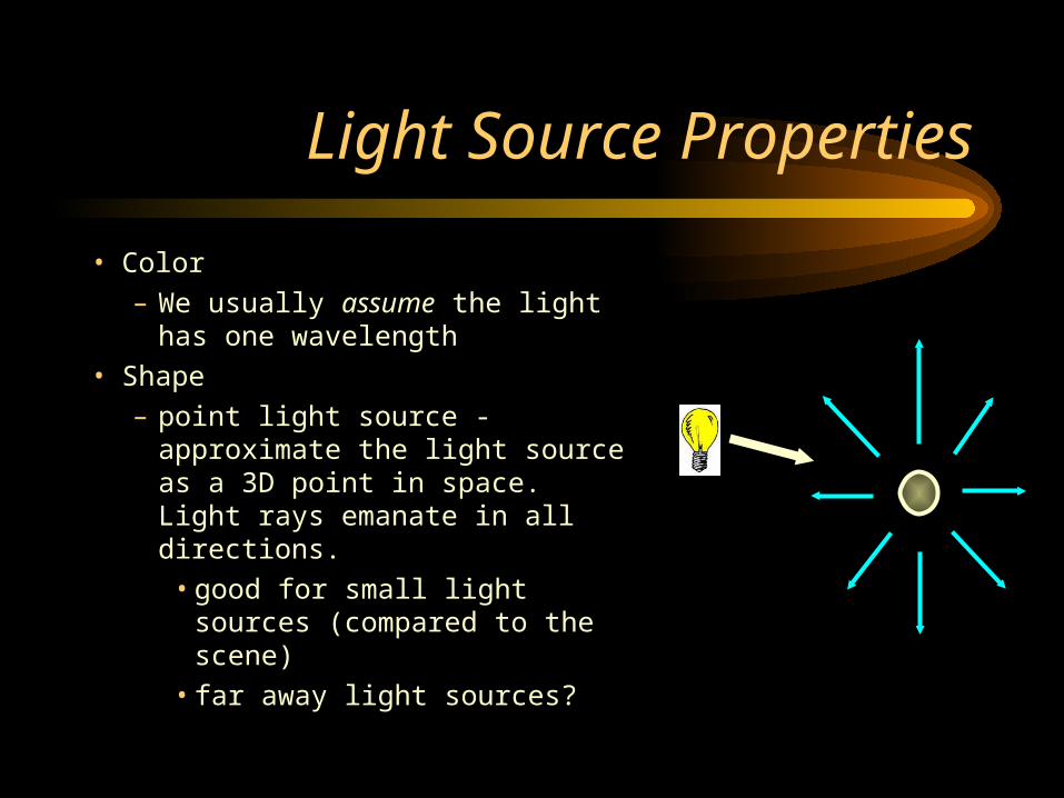
Light Source Properties
• Color– We usually assume the light has
one wavelength• Shape
– point light source - approximate the light source as a 3D point in space. Light rays emanate in all directions.
• good for small light sources (compared to the scene)
• far away light sources?

Distributed Lights
• Light Source Shape continued– distributed light source (not supported natively in
OpenGL) - approximating the light source as a 3D object. Light rays usually emanate in specific directions
• good for larger light sources
• area light sources

Light Source Direction
• In computer graphics, we usually treat lights as rays emanating from a source. The direction of these rays can either be:– Omni-directional (point light source)– Directional angle (spotlights)– Directional (parallel rays)

Light Position
• We can specify the position of a light with an x, y, and z coordinate.– What are some examples?– These lights are called positional lights
• Q: Are there types of lights that we can simplify?
A: Yep! Think about the sun. If a light is significantly far away, we can represent the light with only a direction vector. These are called directional lights. How does this help?

Contributions from lights
• We will breakdown what a light does to an object into three different components. This APPROXIMATES what a light does. To actually compute the rays is too expensive to do in real-time.– Light at a pixel from a light = Ambient +
Diffuse + Specular contributions.
– Ilight = Iambient + Idiffuse + Ispecular

Ambient Term - Background Light
• The ambient term is a HACK!• It represents the approximate
contribution of the light to the general scene, regardless of location of light and object
• Indirect reflections that are too complex to completely and accurately compute
• Iambient = color
Diffuse Term
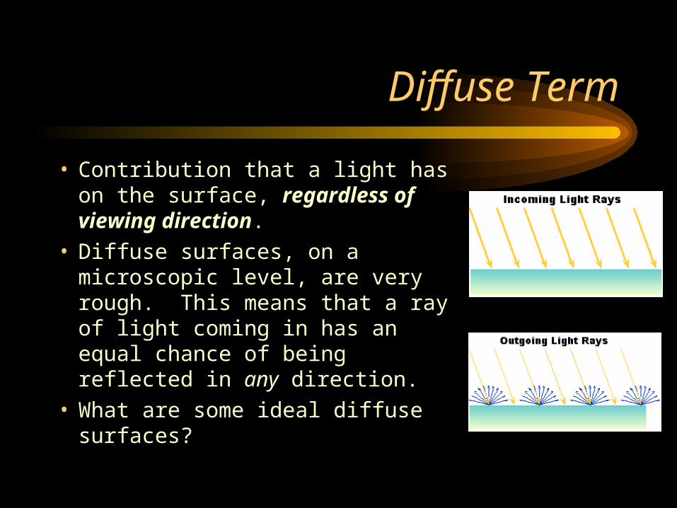
• Contribution that a light has on the surface, regardless of viewing direction.
• Diffuse surfaces, on a microscopic level, are very rough. This means that a ray of light coming in has an equal chance of being reflected in any direction.
• What are some ideal diffuse surfaces?

Lambert’s Cosine Law
• Diffuse surfaces follow Lambert’s Cosine Law• Lambert’s Cosine Law - reflected energy from a small
surface area in a particular direction is proportional to the cosine of the angle between that direction and the surface normal.
• Think about surface area and # of rays

Diffuse Term
• To determine how much of a diffuse contribution a light supplies to the surface, we need the surface normal and the direction on the incoming ray
• What is the angle between these two vectors?
• Idiffuse = kdIlightcos = kdIlight(N . L)
• Ilight = diffuse (intensity) of light
• kd [0..1] = surface diffuse reflectivity
• What CS are L and N in?• How expensive is it?
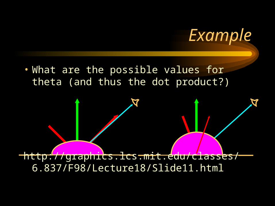
Example
• What are the possible values for theta (and thus the dot product?)
http://graphics.lcs.mit.edu/classes/6.837/F98/Lecture18/Slide11.html

20 Angel: Interactive Computer Graphics 5E © Addison-Wesley 2009
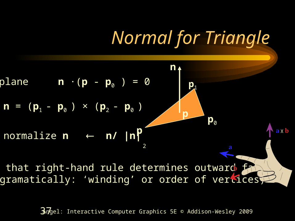
Normal for Triangle
p0
p1
p2
n
plane n ·(p - p0 ) = 0
n = (p1 - p0 ) × (p2 - p0 )
normalize n n/ |n|
p
Note that right-hand rule determines outward face(programatically: ‘winding’ or order of vertices)
X

Specular Reflection
• Specular contribution can be thought of as the “shiny highlight” of a plastic object.
• On a microscopic level, the surface is very smooth. Almost all light is reflected.
• What is an ideal purely specular reflector?
• What does this term depend on?
Viewing Direction
Normal of the Surface
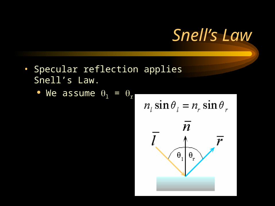
Snell’s Law
• Specular reflection applies Snell’s Law. We assume l = r

Snell’s Law is for IDEAL surfaces
• Most surfaces are not ideal.
• Think about the amount of light reflected at different angles. N
LR
V
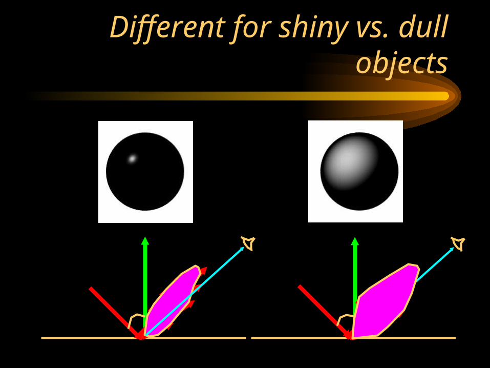
Different for shiny vs. dull objects

Snell’s Law is for IDEAL surfaces
• Think about the amount of light reflected at different angles.
N
LR
V
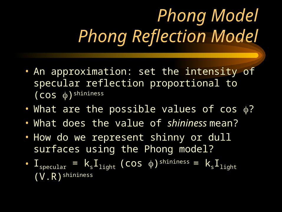
Phong ModelPhong Reflection Model
• An approximation: set the intensity of specular reflection proportional to (cos )shininess
• What are the possible values of cos ?• What does the value of shininess mean?• How do we represent shinny or dull surfaces using
the Phong model?
• Ispecular = ksIlight (cos )shininess = ksIlight (V.R)shininess

27 Angel: Interactive Computer Graphics 5E © Addison-Wesley 2009
The Shininess Coefficient
• Values of between 100 and 200 correspond to metals
• Values between 5 and 10 give surface that look like plastic
cos
90-90

How do we compute R?
• N*(N.L)
• R+L=2N(N.L)
• R = 2N(N.L)-LN
L
R
V
N(N.L)
L

Simplify this
• Instead of R, we compute halfway between L and V.
• We call this vector the halfway vector, H. N
L
R
V
shininessyspecularitlightsspecular HNIkI
VL
VLH
_
H
Combining the terms
• Ambient - the combination of light reflections from various surfaces to produce a uniform illumination. Background light.
• Diffuse - uniform light scattering of light rays on a surface. Proportional to the “amount of light” that hits the surface. Depends on the surface normal and light vector.
• Sepecular - light that gets reflected. Depends on the light ray, the viewing angle, and the surface normal.
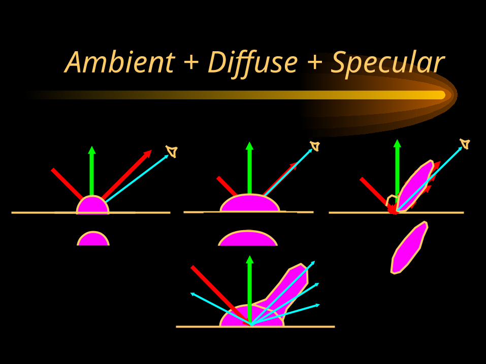
Ambient + Diffuse + Specular

Lighting Equation
Ilambient = light source l’s ambient component
Ildiffuse = light source l’s diffuse component
Ilspecular = light source l’s specular component
kambient = surface material ambient reflectivity
kdiffuse = surface material diffuse reflectivity
kspecular = surface material specular reflectivity
shininess = specular reflection parameter (1 -> dull, 100+ -> very shiny)
1
0
lights
l
shininessspecularldiffuselambientlfinal
shininessspecularspeculardiffusediffuseambientambientfinal
HNkILNkIkII
HNkILNkIkII
speculardiffuseambient
N
LR
V

Attenuation
• One factor we have yet to take into account is that a light source contributes a higher incident intensity to closer surfaces.
• What happens if we don’t do this?
2
210
1
dadaadf

Subtleties
• What’s wrong with:
2
210
1
dadaadf
What’s a good fix?
2
210
1,1min
dadaadf
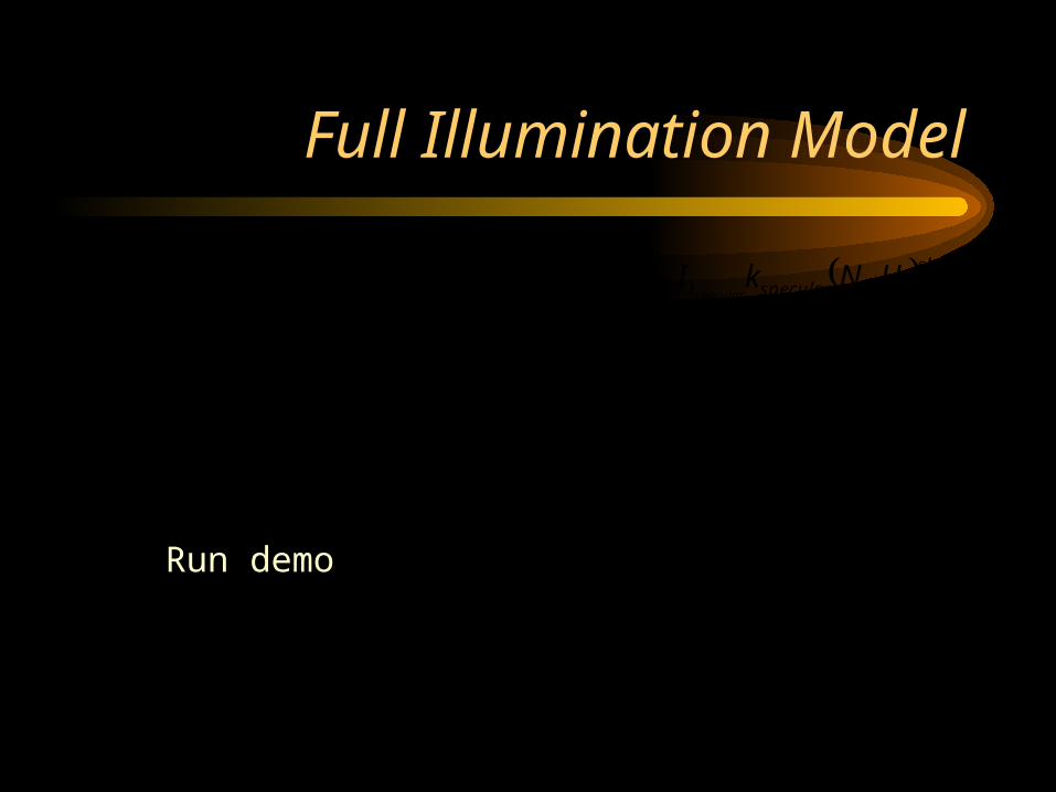
Full Illumination Model
2
210
1,1min
dadaadf
1
0
lights
l
shininessspecularldiffusellambientlfinal HNkILNkIdfkII
speculardiffuseambient
Run demo

36 Angel: Interactive Computer Graphics 5E © Addison-Wesley 2009
Steps in OpenGL lighting
1. Enable lighting and select model
2. Specify normals
3. Specify material properties
4. Specify lights
37 Angel: Interactive Computer Graphics 5E © Addison-Wesley 2009
Normal for Triangle
p0
p1
p2
n
plane n ·(p - p0 ) = 0
n = (p1 - p0 ) × (p2 - p0 )
normalize n n/ |n|
p
Note that right-hand rule determines outward face(programatically: ‘winding’ or order of vertices)
X

38 Angel: Interactive Computer Graphics 5E © Addison-Wesley 2009
Normals• In OpenGL the normal vector is part of the state
• Set by glNormal*()– glNormal3f(x, y, z);– glNormal3fv(p);
• Usually we want to set the normal to have unit length so cosine calculations are correct
– Length can be affected by transformations
– Note that scaling does not preserved length– glEnable(GL_NORMALIZE) allows for
autonormalization at a performance penalty

Shading
• Shading is how we “color” a triangle.
• Constant Shading
• Gouraud Shading

Constant Shading
• Constant Intensity or Flat Shading• One color for the entire triangle• Fast• Good for some objects• What happens if triangles are small?• Sudden intensity changes at borders

Gouraud Shading• Intensity Interpolation Shading• Calculate lighting at the vertices. Then interpolate
the colors

Gouraud Shading
• Relatively fast, only do three calculations
• No sudden intensity changes
• What can it not do?
• What are some approaches to fix this?
• Question, what is the normal at a vertex?

43Angel: Interactive Computer Graphics 5E © Addison-Wesley 2009
Enabling Shading• Shading calculations are enabled by
– glEnable(GL_LIGHTING)
– Once lighting is enabled, glColor() ignored• Must enable each light source individually
– glEnable(GL_LIGHTi) i=0,1…..• Can choose light model parameters
– glLightModeli(parameter, GL_TRUE)•GL_LIGHT_MODEL_LOCAL_VIEWER do not use
simplifying distant viewer assumption in calculation•GL_LIGHT_MODEL_TWO_SIDED shades both sides of
polygons independently
44 Angel: Interactive Computer Graphics 5E © Addison-Wesley 2009
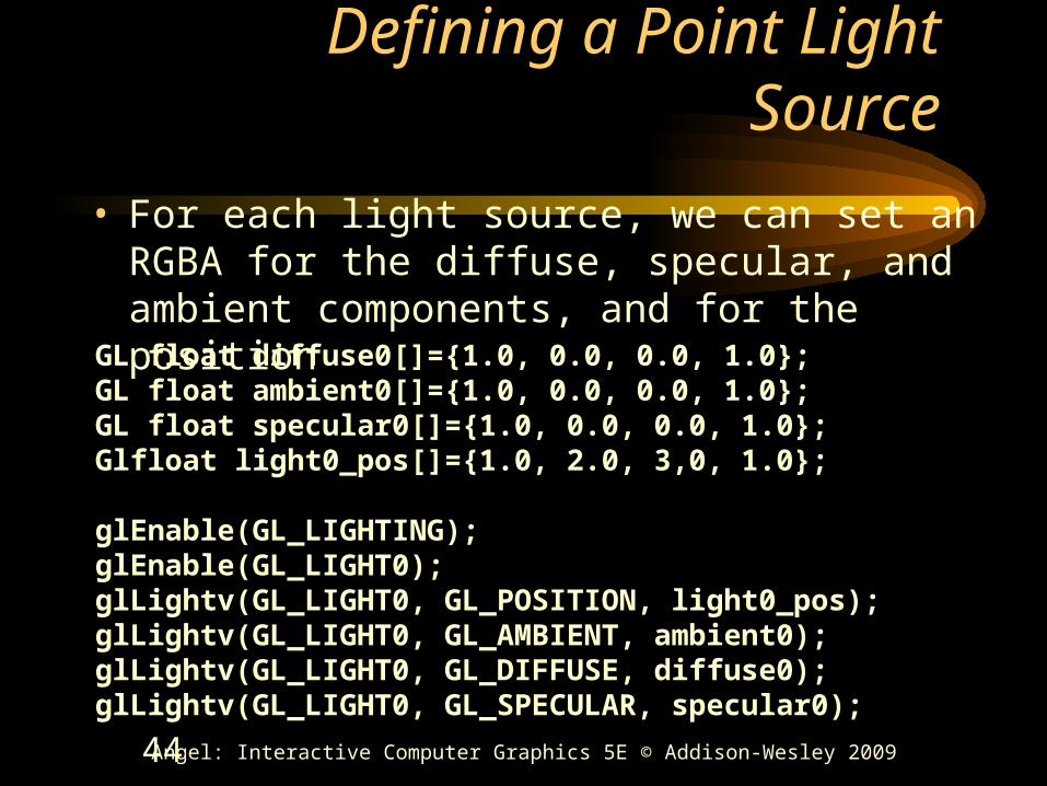
Defining a Point Light Source
• For each light source, we can set an RGBA for the diffuse, specular, and ambient components, and for the position
GL float diffuse0[]={1.0, 0.0, 0.0, 1.0};GL float ambient0[]={1.0, 0.0, 0.0, 1.0};GL float specular0[]={1.0, 0.0, 0.0, 1.0};Glfloat light0_pos[]={1.0, 2.0, 3,0, 1.0};
glEnable(GL_LIGHTING);glEnable(GL_LIGHT0);glLightv(GL_LIGHT0, GL_POSITION, light0_pos);glLightv(GL_LIGHT0, GL_AMBIENT, ambient0);glLightv(GL_LIGHT0, GL_DIFFUSE, diffuse0);glLightv(GL_LIGHT0, GL_SPECULAR, specular0);
45 Angel: Interactive Computer Graphics 5E © Addison-Wesley 2009
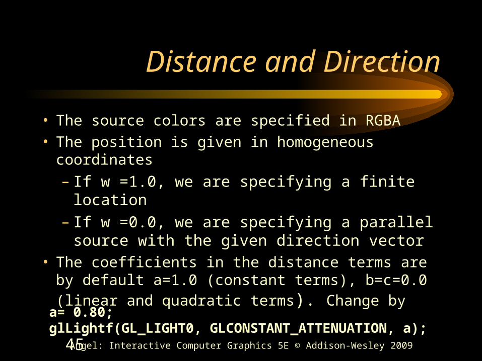
Distance and Direction
• The source colors are specified in RGBA
• The position is given in homogeneous coordinates
– If w =1.0, we are specifying a finite location– If w =0.0, we are specifying a parallel source
with the given direction vector• The coefficients in the distance terms are by default
a=1.0 (constant terms), b=c=0.0 (linear and
quadratic terms). Change bya= 0.80;glLightf(GL_LIGHT0, GLCONSTANT_ATTENUATION, a);
46 Angel: Interactive Computer Graphics 5E © Addison-Wesley 2009
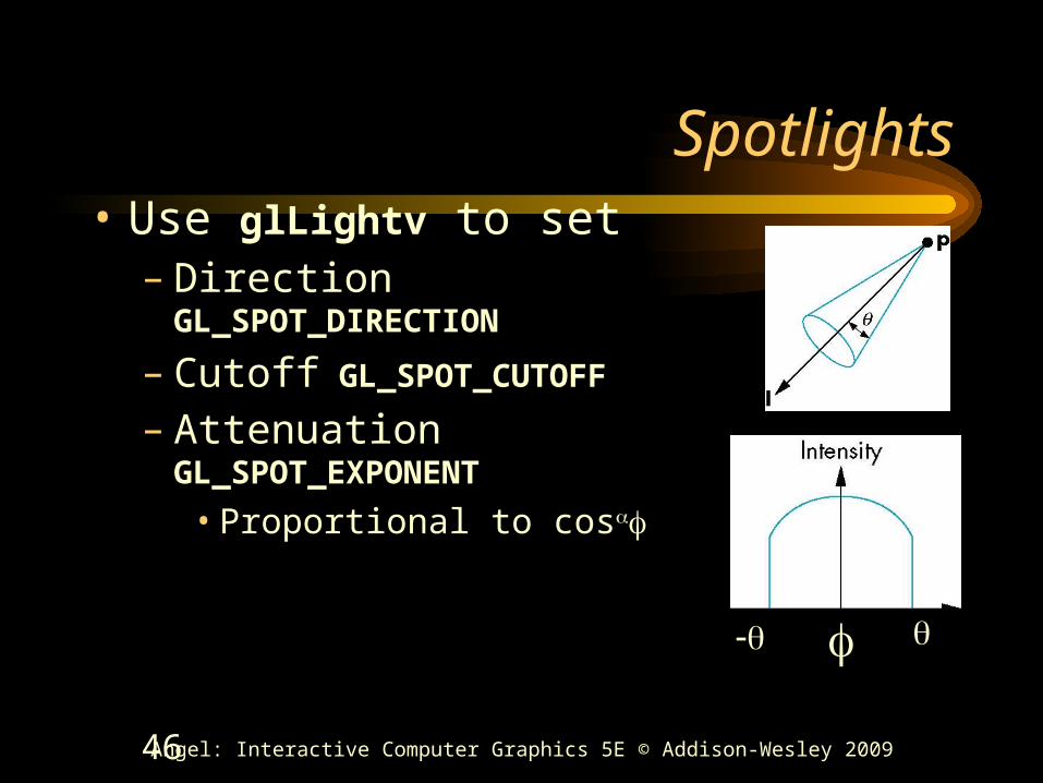
Spotlights• Use glLightv to set
– Direction GL_SPOT_DIRECTION– Cutoff GL_SPOT_CUTOFF– Attenuation GL_SPOT_EXPONENT
• Proportional to cos

47 Angel: Interactive Computer Graphics 5E © Addison-Wesley 2009
Global Ambient Light
• Ambient light depends on color of light sources– A red light in a white room will cause a red
ambient term that disappears when the light is turned off
• OpenGL also allows a global ambient term that is often helpful for testing– glLightModelfv(GL_LIGHT_MODEL_AMBIENT, global_ambient)

48 Angel: Interactive Computer Graphics 5E © Addison-Wesley 2009
Moving Light Sources• Light sources are geometric objects whose
positions or directions are affected by the model-view matrix
• Depending on where we place the position (direction) setting function, we can– Move the light source(s) with the object(s)– Fix the object(s) and move the light source(s)– Fix the light source(s) and move the object(s)– Move the light source(s) and object(s) independently
49 Angel: Interactive Computer Graphics 5E © Addison-Wesley 2009
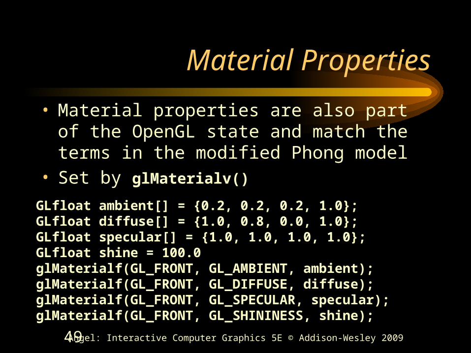
Material Properties
• Material properties are also part of the OpenGL state and match the terms in the modified Phong model
• Set by glMaterialv()
GLfloat ambient[] = {0.2, 0.2, 0.2, 1.0};GLfloat diffuse[] = {1.0, 0.8, 0.0, 1.0};GLfloat specular[] = {1.0, 1.0, 1.0, 1.0};GLfloat shine = 100.0glMaterialf(GL_FRONT, GL_AMBIENT, ambient);glMaterialf(GL_FRONT, GL_DIFFUSE, diffuse);glMaterialf(GL_FRONT, GL_SPECULAR, specular);glMaterialf(GL_FRONT, GL_SHININESS, shine);

50 Angel: Interactive Computer Graphics 5E © Addison-Wesley 2009
Front and Back Faces
• The default is shade only front faces which works correctly for convex objects
• If we set two sided lighting, OpenGL will shade both sides of a surface
• Each side can have its own properties which are set by using GL_FRONT, GL_BACK, or GL_FRONT_AND_BACK in glMaterialf
back faces not visible back faces visible

51 Angel: Interactive Computer Graphics 5E © Addison-Wesley 2009
Emissive Term
• We can simulate a light source in OpenGL by giving a material an emissive component
• This component is unaffected by any sources or transformations
GLfloat emission[] = 0.0, 0.3, 0.3, 1.0);glMaterialf(GL_FRONT, GL_EMISSION, emission);
Related Documents