© 2019 IEEE. This is the author’s version of the article that has been published in IEEE Transactions on Visualization and Computer Graphics. The final version of this record is available at: 10.1109/TVCG.2019.2934658 LightGuider: Guiding Interactive Lighting Design using Suggestions, Provenance, and Quality Visualization Andreas Walch, Michael Schw¨ arzler, Christian Luksch, Elmar Eisemann, and Theresia Gschwandtner Fig. 1. The components of LightGuider : (a) a 3D modeling view to place and modify luminaires, augmented with (b) a provenance tree, depicting several sequential modeling steps and parallel modeling branches, integrating information on the quality of the individual solutions, and providing guidance by pre-simulating and suggesting possible next steps to improve the design. A film-strip-like visualization (c) of screenshots helps to depict the evolution up to the currently selected state. A quality view (d) informs about the fulfillment level of the illumination constraints that need to be met, using bullet charts. Changing the weights of these constraints (e), and therefore, the lighting designer’s focus, triggers an update of the provenance tree node visualizations (reflecting the weights of the constraints in the distribution of the treemap space). Moreover, the defined weights are also considered in the generation of new suggestions, which are tailored towards satisfying constraints with higher weights. Abstract—LightGuider is a novel guidance-based approach to interactive lighting design, which typically consists of interleaved 3D modeling operations and light transport simulations. Rather than having designers use a trial-and-error approach to match their illumination constraints and aesthetic goals, LightGuider supports the process by simulating potential next modeling steps that can deliver the most significant improvements. LightGuider takes predefined quality criteria and the current focus of the designer into account to visualize suggestions for lighting-design improvements via a specialized provenance tree. This provenance tree integrates snapshot visualizations of how well a design meets the given quality criteria weighted by the designer’s preferences. This integration facilitates the analysis of quality improvements over the course of a modeling workflow as well as the comparison of alternative design solutions. We evaluate our approach with three lighting designers to illustrate its usefulness. Index Terms—guidance, 3D modeling, lighting design, provenance, global illumination 1 I NTRODUCTION Lighting design is the process of placing luminaires in a 3D environ- ment in such a way that the emitting light fulfills both technical and aesthetic requirements. Industry norms or customer wishes define the amount of light with a specific distribution (e.g., uniformity is often • Andreas Walch is with VRVis Forschungs GmbH. E-mail: [email protected]. • Michael Schw¨ arzler is with TU Delft. E-mail: [email protected]. • Christian Luksch is with VRVis Forschungs GmbH. E-mail: [email protected]. • Elmar Eisemann is with TU Delft. E-mail: [email protected]. • Theresia Gschwandtner is with TU Wien, Visual Analytics research division. E-mail: [email protected]. Manuscript received xx xxx. 201x; accepted xx xxx. 201x. Date of Publication xx xxx. 201x; date of current version xx xxx. 201x. For information on obtaining reprints of this article, please send e-mail to: [email protected]. Digital Object Identifier: xx.xxxx/TVCG.201x.xxxxxxx a key requirement) to illuminate a certain area (e.g., desktops). Si- multaneously, it is important for lighting designers to pay attention to architectural considerations. In contrast to standard CAD modeling, in which each manipulation typically leads to immediate visual feedback, the process for lighting design is usually decoupled and indirect. Simulating lighting in a new scene configuration is costly, because light propagates through a scene by reflecting off many surfaces. Light characteristics, geometry, and surface material properties (that influence the scattering of the light) all affect the outcome, which makes it impossible to predict an exact appearance without an accurate simulation. Consequently, the result of a modeling step is tough to predict, even for experienced designers. When relying on interactive workflows that approximate the result by relying on recent advances in terms of hardware and algorithms, lighting design takes a trial-and-error-based approach. A designer tries to converge to a solution in which all constraints are fulfilled as good as possible. The process is tiresome and the outcome is usu- 1 arXiv:1907.08553v2 [cs.GR] 7 Oct 2019

Welcome message from author
This document is posted to help you gain knowledge. Please leave a comment to let me know what you think about it! Share it to your friends and learn new things together.
Transcript
© 2019 IEEE. This is the author’s version of the article that has been published in IEEE Transactions on Visualization andComputer Graphics. The final version of this record is available at: 10.1109/TVCG.2019.2934658
LightGuider: Guiding Interactive Lighting Design usingSuggestions, Provenance, and Quality Visualization
Andreas Walch, Michael Schwarzler, Christian Luksch, Elmar Eisemann, and Theresia Gschwandtner
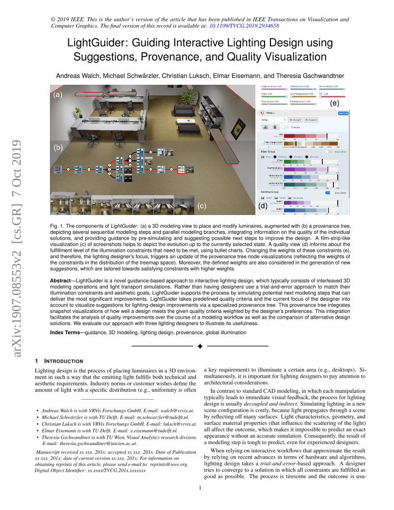
Fig. 1. The components of LightGuider : (a) a 3D modeling view to place and modify luminaires, augmented with (b) a provenance tree,depicting several sequential modeling steps and parallel modeling branches, integrating information on the quality of the individualsolutions, and providing guidance by pre-simulating and suggesting possible next steps to improve the design. A film-strip-likevisualization (c) of screenshots helps to depict the evolution up to the currently selected state. A quality view (d) informs about thefulfillment level of the illumination constraints that need to be met, using bullet charts. Changing the weights of these constraints (e),and therefore, the lighting designer’s focus, triggers an update of the provenance tree node visualizations (reflecting the weights ofthe constraints in the distribution of the treemap space). Moreover, the defined weights are also considered in the generation of newsuggestions, which are tailored towards satisfying constraints with higher weights.
Abstract—LightGuider is a novel guidance-based approach to interactive lighting design, which typically consists of interleaved 3Dmodeling operations and light transport simulations. Rather than having designers use a trial-and-error approach to match theirillumination constraints and aesthetic goals, LightGuider supports the process by simulating potential next modeling steps that candeliver the most significant improvements. LightGuider takes predefined quality criteria and the current focus of the designer intoaccount to visualize suggestions for lighting-design improvements via a specialized provenance tree. This provenance tree integratessnapshot visualizations of how well a design meets the given quality criteria weighted by the designer’s preferences. This integrationfacilitates the analysis of quality improvements over the course of a modeling workflow as well as the comparison of alternative designsolutions. We evaluate our approach with three lighting designers to illustrate its usefulness.
Index Terms—guidance, 3D modeling, lighting design, provenance, global illumination
1 INTRODUCTION
Lighting design is the process of placing luminaires in a 3D environ-ment in such a way that the emitting light fulfills both technical andaesthetic requirements. Industry norms or customer wishes define theamount of light with a specific distribution (e.g., uniformity is often
• Andreas Walch is with VRVis Forschungs GmbH. E-mail: [email protected].• Michael Schwarzler is with TU Delft. E-mail: [email protected].• Christian Luksch is with VRVis Forschungs GmbH. E-mail: [email protected].• Elmar Eisemann is with TU Delft. E-mail: [email protected].• Theresia Gschwandtner is with TU Wien, Visual Analytics research division.
E-mail: [email protected].
Manuscript received xx xxx. 201x; accepted xx xxx. 201x. Date of Publicationxx xxx. 201x; date of current version xx xxx. 201x. For information onobtaining reprints of this article, please send e-mail to: [email protected] Object Identifier: xx.xxxx/TVCG.201x.xxxxxxx
a key requirement) to illuminate a certain area (e.g., desktops). Si-multaneously, it is important for lighting designers to pay attention toarchitectural considerations.
In contrast to standard CAD modeling, in which each manipulationtypically leads to immediate visual feedback, the process for lightingdesign is usually decoupled and indirect. Simulating lighting in a newscene configuration is costly, because light propagates through a sceneby reflecting off many surfaces. Light characteristics, geometry, andsurface material properties (that influence the scattering of the light)all affect the outcome, which makes it impossible to predict an exactappearance without an accurate simulation. Consequently, the result ofa modeling step is tough to predict, even for experienced designers.
When relying on interactive workflows that approximate the resultby relying on recent advances in terms of hardware and algorithms,lighting design takes a trial-and-error-based approach. A designertries to converge to a solution in which all constraints are fulfilled asgood as possible. The process is tiresome and the outcome is usu-
1
arX
iv:1
907.
0855
3v2
[cs
.GR
] 7
Oct
201
9
ally a single local optimum, while all potential alternatives remainundiscovered. Today’s workflows do not support multiple solutionssimultaneously, which further reinforces this problem. Furthermore,it is hard to quantify and compare the potential of different solutionsduring the modeling process.
Approaches to improve the effeciency of lighting design throughautomation have so far not found their way into today’s workflows.One reason is that the parameter space for the possible designs is ex-tremely large. To solve this multi-objective optimization problem, analgorithm has to consider all (theoretically infinitely many) spatialconfigurations of light sources in terms of position and orientation, aswell as the possibility to switch or dim them, increase or decrease theirnumber, or to replace them by a different model. These decisions ofa lighting designer are input parameters of a complex lighting sim-ulation that needs to fulfill given constraints (e.g., all desktops needto be sufficiently illuminated without glaring persons). Furthermore,it is difficult to integrate aesthetic considerations, in non-interactive,simulation-based approaches. This places our work in the field of visualparameter space analysis according to Sedlmair et al. [36]. Moreover,the process of lighting design involves a stepwise improvement of thedesign while constantly evaluating if and how an individual decisionimproved the design and what constraints are affected in which way, aswell as the creation and comparison of multiple alternative designs withsubsequent fine-tuning of design decisions. Efficiently supporting thisprocess requires an interactive visualization of provenance informationincluding quality criteria for alternative branches of designs.
To support interactive lighting design, we propose to structure theworkflow using a Visual Analytics (VA) approach. It combines a 3Dsimulation of the lighting design with an enhanced provenance tree.The tree not only allows lighting designers to keep track of and assessmodeling actions, illumination states, and alternative designs, but it alsoacts as a guidance tool for suggestion-based modeling. The graphicaluser interface elements of our prototypical system can be seen in Fig. 1.Specifically, our contributions are:
• The first interactive modeling system with automatically-generated design suggestions, while at the same time preserv-ing artistic freedom to enable lighting designers to account forarchitectural and aesthetic considerations.
• A guidance mechanism, which takes the current illumination stateand the lighting designer’s preferences into account to suggestpromising design improvements by simulating multiple alterna-tive next steps.
• A visually-enhanced provenance tree to immediately assess thequality of different lighting designs, monitoring the progress ofthe design process, and comparing alternative solutions.
2 RELATED WORK
We structure works related to our novel VA lighting-design solutionwith respect to different scientific fields.
2.1 Lighting DesignLighting design using commercial tools [11, 19, 30] is mainly a 3Dmodeling task (a designer selects, places, and orients light sources), fol-lowed by a global illumination simulation. Accurate simulations, withmultiple light bounces take at least several seconds (using GPU-basedapproaches), but sometimes minutes or even hours to complete. Thisshows the difficulty of trial-and-error-based methods, whose successfor finding a local optimum that fulfills the constraints (such as industrynorms) depends strongly on skill and experience of the designer. Noneof the commercially available tools provide means for comparing solu-tions, modeling suggestions, or anything more than a linear undo/redoqueue. Their big advantage is the complete artistic freedom in termsof parameter selection—an aspect that seems to have a big impact onwhether designers choose a certain system.
In the scientific domain, several approaches automate or simplifylight-source placement and orientation—either with procedural meth-ods as suggested by Schwarz and Wonka [35], or by “painting” the
parts of a scene for illumination [20, 25, 27, 32, 34, 37]. While thesemethods deliver solutions to certain aspects, they ignore the iterative,interactive workflow of lighting designers, in which a large variety ofconsiderations (that may not all be quantifiable) play an important role.Other approaches focus on interactivity, and try to decrease the feed-back cycles between modeling and simulation. Both Luksch et al. [21]and Krosl et al. [18] rely on fast, GPU-based simulations. Despitebeing efficient, they do not offer guided modeling proposals or methodsto explore and compare parallel modeling tracks.
Sorger et al. [40] tackle the problem of comparing different lightconfigurations by linking the simulation results and a spatial viewwith non-spatial ranking and comparison visualizations. Their ideaof setting the importance of certain criteria to compute the overallscore (i.e., giving more weight to certain illumination requirements,to certain scene objects, or to global factors like maintenance costs)during the decision process, has influenced our work. Nevertheless,their approach does not take the modeling process itself into accountand presumes the availability of a high number of valid, pre-simulatedlighting configurations. This assumption rarely holds in real-worldscenarios (due to the trial-and-error-based methodology converging toa single valid solution), raising the need for novel methods that producemultiple solutions in parallel. Other solutions, such as proposed bySimons et al. [39], record light rays and offer visual-analytics tools toexplore, evaluate, and compare light interactions, potentially involvingseveral scenes. Nevertheless, they do not offer suggestions for scenemanipulations to fulfill given constraints.
2.2 Visual Parameter Space AnalysisThe modeling interactions of LightGuider, such as placement of lu-minaires or rearrangement of the scene, are the input parameters of acomplex lighting simulation, in which lighting designers try to generateoutput values, such as glare or direct illumination, that adhere to certainconstraints. Many solutions rely on an exhaustive sampling of theparameter space, such as Bruckner and Moller [5] who pre-computeparticle simulations and then cluster visually similar results. For our usecase it is not possible to conduct a sufficiently dense sampling in rea-sonable time, therefore, approaches relying on pre-computation are notapplicable. Coffey et al. [10] propose a tool for the simulation-drivendesign of biopsy needles. Mechanical engineers pick a specific designand evolve variations from that by dragging interactions. Althoughthey still rely on pre-computed design results, their workflow is similarto LightGuider’s. Flood management and barricade design typicallydeals with a large number of input and environmental parameters. Thedecision support system Visdom [31, 46] employs a tree visualizationthat allows domain experts to evaluate the quality of barricading plans,however, quality in this context can be quantified in damages and waterlevels, while LightGuider needs to convey the fulfillment of complexdesign constraints and aesthetic properties to light designers. Mark etal.’s Design Galleries approach [22] uses thumbnails of images or ani-mations computed in a preprocessing step by sampling a broad range ofinput parameters. Based thereon, Pfister et al. [28] apply this techniquefor the selection of transfer functions in volume rendering.
In accordance with Sedlmair et al. [36], we classify LightGuider asfollows: Utilizing an interactive lighting simulation, lighting designersstart out with a single sample and generate new samples on-the-fly sup-ported by guidance mechanisms (see Sect. 2.4) suggesting alternativesin the parameter space. Immediate feedback of the simulation resultsprovides them with local-to-global navigation. As lighting designersneed to evaluate qualitative as well as quantitative aspects of the sim-ulation output, the domain goals of LightGuider present a mixture ofdesign and engineering domain goals, which are reached through theoptimization of both. As a secondary analysis objective we identify par-titioning in the elaboration of alternative designs to illustrate differenttrade-offs.
2.3 Provenance VisualizationWhen it comes to provenance information in visualization, Raganet al. [29] give a comprehensive overview of the different types ofprovenance information (e.g., the history of data editing, the history of
2
© 2019 IEEE. This is the author’s version of the article that has been published in IEEE Transactions on Visualization andComputer Graphics. The final version of this record is available at: 10.1109/TVCG.2019.2934658
graphical views and visualization types, or the history of interactions)and different purposes of using them in the context of visualization (e.g.,recall different states of the analysis, action recovery, or collaboration).However, there are varying approaches to visualize this information.The most common choice is presenting the provenance tree as a node-link diagram that shows the sequence of states and alternative branchesof a workflow as described by Simmhan et al. [38].
Stitz et al. [43] focus on the scalability of node-link diagrams forencoding a history of analysis workflows. They use filtering, nodeaggregation, as well as a user-interest driven expansion of nodes (i.e., adegree-of-interest function) to make the tree more comprehensible. Ina different work, Stitz et al. [42] use a provenance tree for visualizingautomatically recorded user interactions and visualizations. Again, theyfocus on the efficient retrieval of analysis states by offering differentpossibilities for querying the data (e.g., query by user-generated exam-ples). These works offer sophisticated solutions to scalability problemsof provenance trees in the form of node-link diagrams, as well as so-lutions for efficient interaction with large trees. However, they do notfocus on integrating visual representations of additional information foreach tree node. Our application scenario requires a quick visual com-parison of multiple numerical variables (i.e., illumination constraints)for each state to enable the assessment of changes of quality for eachlighting design action as well as trends of the lighting design processand of alternative workflows.
Bors et al. [1] visualize provenance information for data qualitymanagement. They visualize the history of data editing actions in anode-link diagram augmented with visual information of how manydata records have been deleted or added at each step. Furthermore, theycombine this node-link diagram with a visualization that shows howthe data quality changes over time, giving details of the amount of datarecords that violate different specified data quality metrics. While theypair the provenance tree with an additional visualization (i.e., a stackedbar chart) of multiple numerical variables, this can only be done forone branch of the tree at a time, and thus, the comparison of multiplealternative workflows is not supported.
Besides node-link diagrams, there are examples of other visualiza-tion types used to show provenance information. Viegas et al. [45],for instance, visualize the history of the editing that was applied toa Wikipedia (wikipedia.org) page in a flow-like visualization. Thisvisualization is specifically designed to represent one page with textrunning from top to bottom, but the only interactions it supports (indi-rectly) are “adding text” and “removing text”. Thus, it does not lenditself to our problem scenario. Another approach by Su et al. [44]shows the editing history of illustrations. They provide a superimposedvisualization of two illustration states with “before” states renderedsemi-transparent. Moreover, the illustration is augmented with arrows,icons, and color. Arrows and icons indicate spatial transformations of(parts of) the illustration, while color indicates user changes. This is aspecialized design for the problem at hand and cannot be transferred toour application scenario.
2.4 GuidanceGuidance in visualization as defined by Ceneda at al. [6] can be foundin various forms and application scenarios. However, only a fewapproaches relate to our problem at hand. Bouali et al. [3] presenta guidance approach to automatically generate a set of information-visualization designs appropriate for the given data and tasks. A selec-tion of the most useful visualization mappings is input to the guidancemechanism, and influences future suggestions. O’Donovan et al. [24]present a similar approach that helps in creating graphic design layouts.The system interactively suggests changes in the position, scale, andalignment of elements that are placed on a page. Both systems presentguidance approaches to optimize a design.
Yang et al. [47] present a guidance approach that helps to discoverinteresting data and patterns based on the system user’s interests. Theyprovide a system to extract, combine, refine, and visualize such find-ings of interest. They distinguish between user-driven and data-drivenfindings. In our work we combine user-driven (i.e., the user chooseswhich areas and which illumination constraints are more important
than others) with data-driven (i.e., optimizing the current design withrespect to specified illumination constraints) steering of the guidancesuggestions.
3 BACKGROUND
In this section we define important concepts in the context of lightingdesign.
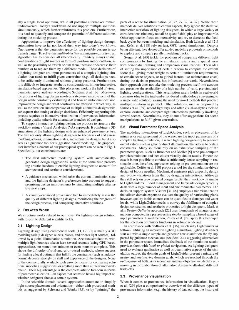
3.1 Generating Illumination DataGlobal light transport simulations give an estimation of the propagationof light from the sources via several bounces off scene surfaces to eachpoint in the scene. A realistic visualization of the light distribution ina 3D space helps to get an aesthetic impression of the result, whilethe quality of a lighting design is typically illustrated using a falsecolor coding. Lighting designers face many regulations and constraintsgiven by industry norms and customers, such as specific regions thathave to be illuminated with a minimum amount of light and a uniformdistribution, or certain critical positions for which no blinding shouldoccur (e.g., a person sitting at a desk). For this reason, designers rely onmeasuring surfaces (measuring incoming light in this area) and glareprobes (simulating a person’s field of view from a certain point anddirection) that are placed in the scene (see Fig. 2). They are typicallylinked to scene objects that have a certain semantic meaning (e.g., adesk) with specific norm-based target values assigned to them (seeSect. 3.2). In our approach, the light transport simulation is performedusing a GPU-based many-light approach similar to Luksch et al. [21],and the incoming light is stored in the texels of a light map that coversall surface geometry.
Fig. 2. A measuring surface on the desktop, and glare probes (simu-lating a person’s field of view while working on this desk) are used togather illumination information, such as the average illuminance and theuniformity on an area, or if a person is likely to be blinded. Dependingon the semantics, the target values of the measurement objects are setaccording to industry norms. Only designs in which all of these targetvalues are reached are considered valid. To fully support linking andbrushing in case of occlusions, outline-based highlighting enhancementsand semi-transparent area overlays are rendered without depth-testing.
Input Parameters. Similar to Sorger et al. [40] and accordingto the classification by Sedlmair et al. [36], we distinguish betweencontrol parameters (the lights in the scene, including their position andorientation), model parameters (defining the accuracy of the simulation,e.g., the resolution of the light maps, or the number of bounces) andenvironmental parameters (the scene with its materials, additionalillumination by sunshine / weather, etc.) as inputs for our simulation. Inour work we focus solely on the modification of the control parameters.As a simulation run is always coupled to a certain configuration of lightsources modeled by the designer or proposed by our guidance system,we refer to them together as modeling state or illumination state in thispaper.
3.2 Illumination ConstraintsApart from aesthetic considerations, we use the following quantifiable,industry-established metrics (e.g., as described in Zumtobel’s LightingHandbook [48]) to rate the quality of a solution:
3
Local indicators. The semantics of objects or regions in the scene,e.g., a desktop, are linked with local indicators. By assigning measuringsurfaces, statistical aggregations of the individual measurements (i.e.,of all the texels of the measuring surface) can be generated to definethe illumination quality. We focus on the industrially most-widelyused indicators, namely Average Illuminance (AVG), Uniformity G1 (=min/avg), and Uniformity G2 (= min/max).
Person-oriented indicators. Contrary to Sorger et al. [40], wealso take a view-dependent criterion into account—the Unified GlareRating (UGR) defined by the CIE [9], giving an estimation of whether aperson will be blinded by the lights in the scene. The optimal placementand configuration of the glare probes (simulating a person’s field ofview) is not as well-defined as for measuring surfaces, because of thetheoretical possibility of infinitely many probes. The designer choosesa feasible number at relevant spots.
Global indicators. We use the meta data of the luminaires to deriveglobal indicators, which are not measured in the simulation, nor linkedto certain objects. We consider Color Temperature in Kelvin (K) bycomputing the weighted average (per Lumen) of all light sources in agroup, and the Colour Rendering Index (CRI), for which we take theminimum value of the corresponding lights.
According to the DIN Standard EN 12464-1 [12] or customer re-quirements, the target values for these indicators are set per measuringsurface, glare probe, or the whole scene, and are referred to as illumina-tion constraints. We consider a solution valid if all of these illuminationconstraints are reached. Note that subjective opinions (such as aesthet-ics) could still disqualify a valid solution.
3.3 Interactions and Tasks in Lighting DesignThe actions that a lighting designer traditionally performs to find asuitable solution fulfilling the illumination constraints after setting upthe scene and defining the target values can coarsely be described bythe following workflow:
1. Selection, placement, and alignment of luminaires, followed by asimulation run
2. Verification of all illumination constraints followed by the de-signer’s choice of which requirement to improve
3. Selection of a modeling action (e.g., change the height of a light)that is likely to improve the selected illumination requirement andmaintains the aesthetic goals, followed by a new simulation run
4. Repetition of the two previous steps until all illumination con-straints are fulfilled and the aesthetic expectations are met
This iterative approach typically leads to the evaluation of only “onepath to a valid solution”. Only in cases in which the customer is not sat-isfied, further, alternative solutions are generated. Moreover, it shouldbe noted that since the different illumination constraints are connected,a modeling action would usually not only improve the targeted con-straint, but might also have negative effects on other constraints (e.g.,lowering a light would improve the Avg. Illuminance on a desktop butalso enhance Glare).
4 LIGHTGUIDER DESIGN REQUIREMENTS
We designed LightGuider to address the trial-and-error work-flow oflighting design, by automatically generating new solutions and visuallyguiding the lighting designer to find an optimal solution. Moreover, wepreserve the creative procedure of lighting design by enabling the de-signer to try and to compare different directions and consider aestheticaspects in addition to numerically defined illumination constraints.
In the course of more than ten years of tight collaboration with light-ing designers, we identified the following aspects required to improvethe lighting-design process:
R1 Lighting design should be interactive to account for artistic pref-erences.
R2 A 3D simulation of current and previous lighting designs areimportant to evaluate aesthetic considerations.
R3 The trial-and-error-based methodology should be superseded bya good visual overview of the history of modeling operations,parallel design branches, and intuitive restoration of modelingstates.
R4 A fast visual summary of the quality of each state (i.e., how well itmeets the illumination constraints) is required to evaluate the im-pact of certain modeling operations, the tendency of improvementwithin a modeling workflow, different intermediate solutions, aswell as parallel design branches.
R5 Visual means for a fast comparison of these states and solutionsshould be provided.
R6 The multi-objective optimization problem of finding promisinglight configurations within a huge parameter space should beguided by automatic means.
5 LIGHTGUIDER VISUALIZATION DESIGN & INTERACTIONS
To make informed decisions about our visualization and interactiondesign we analyzed (1) the data we need to communicate, (2) theintended users of the approach, as well as (3) the tasks they have tosolve (as described by Miksch and Aigner [23]). The data consistsof multiple aspects: the scene for which a lighting design should befound together with placed light sources, the outcome of light transportsimulations (see Sect. 3.1), the illumination constraints that should bemet (see Sect. 3.2), as well as the history of modeling operations. OurVA approach is specifically developed for lighting designers, who areour expected user group. These lighting designers need to choose aset of multiple lighting-design modeling parameters to find a lightingsolution that fulfills not only their aesthetic requirements but also anumber of illumination constraints.
5.1 System OverviewLightGuider is an enhancement to a lighting design prototype focusedon interactive editing of a 3D scene (R1) coupled with a fast lightsimulation (see Fig. 1). It consists of a spatial 3D editing, simulationand visualization view (see Sect. 5.2), which is partly and transparentlyoverlaid by the core component of our novel system—a graph-based2D visualization that is used to depict the modeling progress and toguide lighting designers to reach their goals (see Sect. 5.4). Integratedinto the existing user interface of the software, additional panels givedetailed information on a modeling state (see Sect. 5.3) and allow foradjusting the importance of illumination constraints and measuringsurfaces (see Sect. 5.6). All of these components are connected withregards to linking and brushing.
We tightly integrated our LightGuider approach into an establishedand well-evaluated lighting design tool by Luksch et al. [21], whichsupports placing of light sources, setting their parameters, and evalu-ating light transport simulations in a 3D scene, and thus, avoiding theneed for the designers to learn a new environment. This also allowedus to evaluate whether our novel attempt to guide the workflow wasaccepted by the domain experts, or whether they would rather prefertheir traditional methods while solving the given tasks (see Sect. 8).
5.2 3D ViewThe freely navigable 3D view (see Fig. 1 (a)) is a combined visual-ization, editing, and simulation interface. It displays the illuminated3D scene using the simulation information stored in the light maps inreal-time. Using typical manipulation tools known from CAD tools,light sources (i.e., the simulation’s control parameters) can be arbitrar-ily placed, moved, rotated, removed, exchanged, dimmed, and grouped.After each modification, the simulation is immediately restarted asyn-chronously, continuously converging to a new result while the designercontinues to freely interact with the scene. Furthermore, measuringsurfaces and glare probes can be placed and configured according tothe requirements. The visualization of measuring surfaces within their
4
© 2019 IEEE. This is the author’s version of the article that has been published in IEEE Transactions on Visualization andComputer Graphics. The final version of this record is available at: 10.1109/TVCG.2019.2934658
(a) (b) (c) (d)
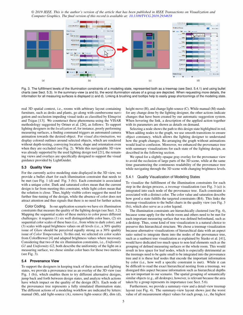
Fig. 3. The fulfillment levels of the illumination constraints of a modeling state, represented both as a treemap (see Sect. 5.4.1) and using bulletcharts (see Sect. 5.3). In the summary-view (a and b), the worst illumination values of a group are depicted. When requesting more details, theinformation for all measuring surfaces is displayed (c and d). Linking & brushing and tooltips help to easily grasp shortcomings of the modeling state.
real 3D spatial context, i.e., rooms with arbitrary layout containingfurniture, such as desks and plants, go along with cumbersome navi-gation and occlusion impeding visual tasks as classified by Elmqvistand Tsigas [13]. We counteract these phenomena using the VISARmethodology suggested by Ortner et al. [26], as follows: To supportlighting designers in the localization of, for instance, poorly performingmeasuring surfaces, a finding command triggers an automated cameraanimation towards the desired object. For visual discrimination, wedisplay colored outlines around selected objects, which are renderedwithout depth-testing, conveying location, shape and orientation evenwhen they are occluded (see Fig. 2). While this navigatable 3D viewwas already supported by the used lighting design tool [21], the remain-ing views and overlays are specifically designed to support the visualguidance provided by LightGuider.
5.3 Quality ViewFor the currently active modeling state displayed in the 3D view, weprovide a bullet chart for each illumination constraint that needs tobe met (see Fig. 1 (d) and Fig. 3 (b)). Each constraint is associatedwith a unique color. Dark and saturated colors mean that the currentdesign is far from meeting this constraint, while light colors mean thatthe solution is close. Thus, highly visible colors suggest the need forfurther fine-tuning of the design, while the absence of color does notattract attention and thus signals that there is no need for further action.
Color Coding. In our application scenario we have six illuminationconstraints that measure the quality of the lighting design (see Sect. 3.2).Mapping the sequential scales of these metrics to color poses differentchallenges: it requires (1) six well distinguishable color hues, (2) sixsequential color scales of these hues (i.e., from white to dark color), and(3) scales with equal brightness values on all levels (i.e., a 30% qualityissue of Glare should be perceived equally strong as a 30% qualityissue of Color Temperature). To this end, we selected six color scalesfrom ColorBrewer [4] and adapted brightness values where necessary.Considering that two of the six illumination constraints, i.e., UniformityG1 and Uniformity G2, both describe the uniformity of the light on ameasuring surface, we chose similar color hues for those two metrics(see Fig. 3).
5.4 Provenance ViewTo support the designers in keeping track of their actions and lightingstates, we provide a provenance tree as an overlay of the 3D view (seeFig. 1 (b)), which enables them to try different alternative designs,jump back and forth between design states, and analyze which actionshave which impact on the quality of the design (R3). Each node ofthe provenance tree represents a fully simulated illumination state.The different actions of a modeling workflow are indicated by letters:manual (M), add light-source (A), remove light-source (R), dim (d),
height move (H), and change light-source (C). While manual (M) standsfor any change done by the lighting designer, the other actions indicatechanges that have been created by our automatic suggestion system.When hovering the link, a description of the applied action togetherwith its parameters are shown as details on demand.
Selecting a node shows the path to this design state highlighted in red.When adding nodes to the graph, we use smooth transitions to ensureobject constancy, which allows the lighting designer to understandhow the graph changes. Re-arranging the graph without animationswould lead to confusion. Moreover, we enhanced the provenance treewith summary visualizations for each state of the lighting design, asdescribed in the following section.
We opted for a slightly opaque gray overlay for the provenance viewto avoid the occlusion of large parts of the 3D scene, while at the sametime guaranteeing the continuous readability of the provenance treewhile navigating through the 3D scene with changing brightness levels.
5.4.1 Quality Visualization of Modeling States
To visualize the fulfillment of the illumination constraints for eachstep in the design process, a treemap visualization (see Fig. 3 (a)) isintegrated into each node of the provenance tree. Each constraint isassociated with a distinct color. The color value and saturation describehow good a state fulfills the targeted constraints (R4). This links thetreemap visualization to the bullet charts in the quality view (see Fig. 3(b)), which also serve as a color legend.
The illumination constraints are hierarchically clustered (see Fig. 4),because some apply for the whole room and others need to be met foreach important measuring surface that was defined beforehand, such asa desktop. Thus, some kind of tree visualization is a natural choice topreserve this hierarchical structure. We chose a treemap visualizationbecause alternative visualizations of hierarchical data with an aspectratio suited to integrate them into the nodes of the provenance tree,such as a sunburst tree visualization as explained by Stasko et al. [41],would have dedicated too much space to non-leaf elements such as thegrouping of defined measuring surfaces or the whole room. This wouldresult in less space for leaf nodes, which is especially detrimental asthe treemaps need to be quite small to be integrated into the provenancetree and it is these leaf nodes that encode the important informationby color (i.e., how well a specific constraint is met). While it canbe difficult to read the exact hierarchical nesting from a treemap, wedisregard this aspect because information such as hierarchical depthsare not important in our scenario. The spatial grouping of semanticallysimilar objects (e.g., all desktops), however, is relevant because the areataken by a group represents its importance (see Sect. 5.6).
Furthermore, we provide a summary-view and a detail-view treemaplayout (see Fig. 4). The summary-view layout shows just the worstvalue of all measurement object values for each group, i.e., the highest
5
measurement surf. 1
measurement surf. 2
AVG G1 G2
room
global indicators
group 3: persons
glare probe 1 (UGR)
group 1: desktops
group 2: floors
local indicators
other indicators
measurement surf. 3
CRIK
AVG G1 G2
AVG G1 G2
person-oriented ind.
AVG G1 G2
AVG G1 G2
UGR
glare probe 2 (UGR)
glare probe 3 (UGR) Summary View
CRI
KUGR
(glare probe 1)
AV
G m
s 1
CRI
K
UGR(group3)
AVG(group1)
G1(group1)
G2(group1)
G2(group2)
AVG(group2)
G1(group2)
UGR(glare
probe 2)
UGR(glare
probe 3)
AV
G m
s 2
G1 m
s 1G
1 ms 2
G2 m
s 1G
2 ms 2
AV
G m
s 3
G1 m
s 3
G2 m
s 3
Detail View
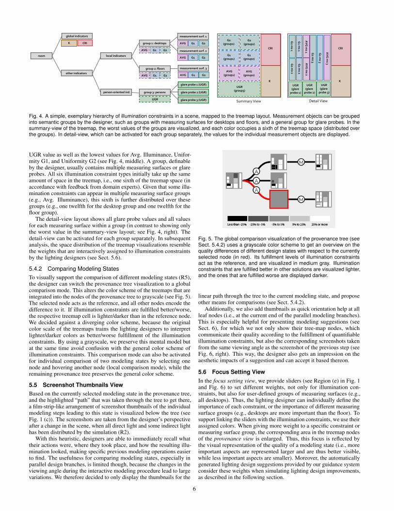
Fig. 4. A simple, exemplary hierarchy of illumination constraints in a scene, mapped to the treemap layout. Measurement objects can be groupedinto semantic groups by the designer, such as groups with measuring surfaces for desktops and floors, and a general group for glare probes. In thesummary-view of the treemap, the worst values of the groups are visualized, and each color occupies a sixth of the treemap space (distributed overthe groups). In detail-view, which can be activated for each group separately, the values for the individual measurement objects are displayed.
UGR value as well as the lowest values for Avg. Illuminance, Unifor-mity G1, and Uniformity G2 (see Fig. 4, middle). A group, definableby the designer, usually contains multiple measuring surfaces or glareprobes. All six illumination constraint types initially take up the sameamount of space in the treemap, i.e., one sixth of the treemap space (inaccordance with feedback from domain experts). Given that some illu-mination constraints can appear in multiple measuring surface groups(e.g., Avg. Illuminance), this sixth is further distributed over thesegroups (e.g., one twelfth for the desktop group and one twelfth for thefloor group).
The detail-view layout shows all glare probe values and all valuesfor each measuring surface within a group (in contrast to showing onlythe worst value in the summary-view layout; see Fig. 4, right). Thedetail-view can be activated for each group separately. In subsequentanalysis, the space distribution of the treemap visualizations resemblethe weights that are interactively assigned to illumination constraintsby the lighting designers (see Sect. 5.6).
5.4.2 Comparing Modeling StatesTo visually support the comparison of different modeling states (R5),the designer can switch the provenance tree visualization to a globalcomparison mode. This alters the color scheme of the treemaps that areintegrated into the nodes of the provenance tree to grayscale (see Fig. 5).The selected node acts as the reference, and all other nodes encode thedifference to it. If illumination constraints are fulfilled better/worse,the respective treemap cell is lighter/darker than in the reference node.We decided against a diverging color scheme, because the originalcolor scale of the treemaps trains the lighting designers to interpretlighter/darker colors as better/worse fulfillment of the illuminationconstraints. By using a grayscale, we preserve this mental model butat the same time avoid confusion with the general color scheme ofillumination constraints. This comparison mode can also be activatedfor individual comparison of two modeling states by selecting onenode and hovering another node (local comparison mode), while theremaining provenance tree preserves the general color scheme.
5.5 Screenshot Thumbnails ViewBased on the currently selected modeling state in the provenance tree,and the highlighted “path” that was taken through the tree to get there,a film-strip-like arrangement of screenshot thumbnails of the individualmodeling steps leading to this state is visualized below the tree (seeFig. 1 (c)). The screenshots are taken from the designer’s perspectiveafter a change in the scene, when all direct light and some indirect lighthas been distributed by the simulation (R2).
With this heuristic, designers are able to immediately recall whattheir actions were, where they took place, and how the resulting illu-mination looked, making specific previous modeling operations easierto find. The usefulness for comparing modeling states, especially inparallel design branches, is limited though, because the changes in theviewing angle during the interactive modeling procedure lead to largevariations. We therefore decided to only display the thumbnails for the
Fig. 5. The global comparison visualization of the provenance tree (seeSect. 5.4.2) uses a grayscale color scheme to get an overview on thequality differences of different design states with respect to the currentlyselected node (in red). Its fulfillment levels of illumination constraintsact as the reference, and are visualized in medium gray. Illuminationconstraints that are fulfilled better in other solutions are visualized lighter,and the ones that are fulfilled worse are displayed darker.
linear path through the tree to the current modeling state, and proposeother means for comparisons (see Sect. 5.4.2).
Additionally, we also add thumbnails as quick orientation help at allleaf nodes (i.e., at the current end of the parallel modeling branches).This is especially helpful for presenting modeling suggestions (seeSect. 6), for which we not only show their tree-map nodes, whichcommunicate their quality according to the fulfillment of quantifiableillumination constraints, but also the corresponding screenshots takenfrom the same viewing angle as the screenshot of the previous step (seeFig. 6, right). This way, the designer also gets an impression on theaesthetic impacts of a suggestion and can accept it based thereon.
5.6 Focus Setting ViewIn the focus setting view, we provide sliders (see Region (e) in Fig. 1and Fig. 6) to set different weights, not only for illumination con-straints, but also for user-defined groups of measuring surfaces (e.g.,all desktops). Thus, the lighting designer can individually define theimportance of each constraint, or the importance of different measuringsurface groups (e.g., desktops are more important than the floor). Tosupport linking the sliders with the illumination constraints, we use theirassigned colors. When giving more weight to a specific constraint ormeasuring surface group, the corresponding area in the treemap nodesof the provenance view is enlarged. Thus, this focus is reflected bythe visual representation of the quality of a modeling state (i.e., moreimportant aspects are represented larger and are thus better visible,while less important aspects are smaller). Moreover, the automaticallygenerated lighting design suggestions provided by our guidance systemconsider these weights when simulating lighting design improvements,as described in the following section.
6
© 2019 IEEE. This is the author’s version of the article that has been published in IEEE Transactions on Visualization andComputer Graphics. The final version of this record is available at: 10.1109/TVCG.2019.2934658
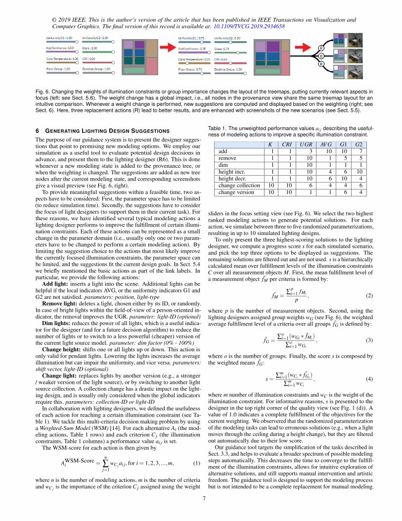
Fig. 6. Changing the weights of illumination constraints or group importance changes the layout of the treemaps, putting currently relevant aspects infocus (left; see Sect. 5.6). The weight change has a global impact, i.e., all nodes in the provenance view share the same treemap layout for anintuitive comparison. Whenever a weight change is performed, new suggestions are computed and displayed based on the weighting (right; seeSect. 6). Here, three replacement actions (R) lead to better results, and are enhanced with screenshots of the new scenarios (see Sect. 5.5).
6 GENERATING LIGHTING DESIGN SUGGESTIONS
The purpose of our guidance system is to present the designer sugges-tions that point to promising new modeling options. We employ oursimulation as a useful tool to evaluate potential design decisions inadvance, and present them to the lighting designer (R6). This is donewhenever a new modeling state is added to the provenance tree, orwhen the weighting is changed. The suggestions are added as new treenodes after the current modeling state, and corresponding screenshotsgive a visual preview (see Fig. 6, right).
To provide meaningful suggestions within a feasible time, two as-pects have to be considered: First, the parameter space has to be limited(to reduce simulation time). Secondly, the suggestions have to considerthe focus of light designers (to support them in their current task). Forthese reasons, we have identified several typical modeling actions alighting designer performs to improve the fulfillment of certain illumi-nation constraints. Each of these actions can be represented as a smallchange in the parameter domain (i.e., usually only one or two param-eters have to be changed to perform a certain modeling action). Bylimiting the suggestion choice to the actions that most likely improvethe currently focused illumination constraints, the parameter space canbe limited, and the suggestions fit the current design goals. In Sect. 5.4we briefly mentioned the basic actions as part of the link labels. Inparticular, we provide the following actions:
Add light: inserts a light into the scene. Additional lights can behelpful if the local indicators AVG, or the uniformity indicators G1 andG2 are not satisfied. parameters: position, light-type
Remove light: deletes a light, chosen either by its ID, or randomly.In case of bright lights within the field-of-view of a person-oriented in-dicator, the removal improves the UGR. parameter: light-ID (optional)
Dim lights: reduces the power of all lights, which is a useful indica-tor for the designer (and for a future decision algorithm) to reduce thenumber of lights or to switch to a less powerful (cheaper) version ofthe current light source model. parameter: dim factor (0% - 100%)
Change height: shifts one or all lights up or down. This action isonly valid for pendant lights. Lowering the lights increases the averageillumination but can impair the uniformity, and vice versa. parameters:shift vector, light-ID (optional)
Change light: replaces lights by another version (e.g., a stronger/ weaker version of the light source), or by switching to another lightsource collection. A collection change has a drastic impact on the light-ing design, and is usually only considered when the global indicatorsrequire this. parameters: collection-ID or light-ID
In collaboration with lighting designers, we defined the usefulnessof each action for reaching a certain illumination constraint (see Ta-ble 1). We tackle this multi-criteria decision making problem by usinga Weighted-Sum Model (WSM) [14]. For each alternative Ai (the mod-eling actions, Table 1 rows) and each criterion C j (the illuminationconstraints, Table 1 columns) a performance value ai j is set.
The WSM-score for each action is then given by
AWSM-Scorei =
n
∑j=1
wC j ai j, for i = 1,2,3, ...,m, (1)
where n is the number of modeling actions, m is the number of criteriaand wC j is the importance of the criterion C j assigned using the weight
Table 1. The unweighted performance values ai j describing the useful-ness of modeling actions to improve a specific illumination constraint.
K CRI UGR AV G G1 G2add 1 1 3 10 10 7remove 1 1 10 1 5 5dim 1 1 10 1 1 1height incr. 1 1 10 4 6 10height decr. 1 1 10 6 10 4change collection 10 10 6 4 4 6change version 10 10 1 1 6 4
sliders in the focus setting view (see Fig. 6). We select the two highestranked modeling actions to generate potential solutions. For eachaction, we simulate between three to five randomized parameterizations,resulting in up to 10 simulated lighting designs.
To only present the three highest-scoring solutions to the lightingdesigner, we compute a progress score s for each simulated scenario,and pick the top three options to be displayed as suggestions. Theremaining solutions are filtered out and are not used. s is a hierarchicallycalculated mean over fulfillment levels of the illumination constraintsC over all measurement objects M. First, the mean fulfillment level ofa measurement object ¯fM per criteria is formed by:
¯fM =∑
pi=1 fMi
p, (2)
where p is the number of measurement objects. Second, using thelighting designers assigned group weights wG (see Fig. 6), the weightedaverage fulfillment level of a criteria over all groups fG is defined by:
fG =∑
oi=1(wGi ∗ fMi)
∑oi=1 wGi
, (3)
where o is the number of groups. Finally, the score s is composed bythe weighted means fG:
s =∑
mi=1(wCi ∗ ¯fGi)
∑mi=1 wCi
, (4)
where m number of illumination constraints and wC is the weight of theillumination constraint. For informative reasons, s is presented to thedesigner in the top right corner of the quality view (see Fig. 1 (d)). Avalue of 1.0 indicates a complete fulfillment of the objectives for thecurrent weighting. We observered that the randomized parameterizationof the modeling tasks can lead to erroneous solutions (e.g., when a lightmoves through the ceiling during a height change), but they are filteredout automatically due to their low score.
Our guidance tool targets the simplification of the tasks described inSect. 3.3, and helps to evaluate a broader spectrum of possible modelingsteps automatically. This decreases the time to converge to the fulfill-ment of the illumination constraints, allows for intuitive exploration ofalternative solutions, and still supports manual intervention and artisticfreedom. The guidance tool is designed to support the modeling processbut is not intended to be a complete replacement for manual modeling.
7
7 IMPLEMENTATION
We implemented our proposed interactive visualization and guidancemethod in an existing lighting design software prototype with industry-standard modeling tools, a database with measured light sources, andan optimized, state-of-the-art GPU-based simulation kernel [21]. Thesoftware was extended by integrating web-based visualizations (primar-ily created with D3 [2]) using the Chromium browser libraries [15],and were linked to the 3D view via websockets. In our test scenes, atypical simulation run takes about 1 to 5 seconds to complete on ourdesktop workstation with an Intel i5 7660K CPU, 32GB RAM and aNVIDIA GTX 1080 graphics card at 1920x1080 resolution. The texelsize of the light map corresponds to a real-world area of 1x1cm, andwe limited the number of light bounces to three. The user study (seeSect. 8) was conducted using the same system and settings.
8 EVALUATION
We conducted a qualitative user study with three lighting designers.
8.1 Study DesignWe recruited three lighting designers as study participants to test ourprototype. None of them was involved in the design process nor did theysee our prototype before. We opted for a qualitative evaluation, whichis effective when working with domain experts to better understand howthey interact with the prototype, to observe which insights the expertscan derive from the visualizations, to collect detailed feedback of theusefulness of the prototype, and how it fits to their workflow [16, 17].We conducted individual testing sessions with one developer and therespective study participant.
The sessions started with a short interview to learn about the evalua-tors’ experience with visualizations and what tools they are currentlyusing. We introduced LightGuider, its functionality, and explained thelighting scenario used for this session within 15 minutes. We encour-aged the study participant to think aloud while performing the tasksmentioned below. The participants finished the tasks in approximately20 minutes, without any further training. We then conducted a semi-structured interview to learn about their impressions of the prototype.
• Task 1: Identify needs for improvement. Manipulate the pre-placed lights manually and use the bullet charts and provenancetree to reason if the lighting design changed for the better orworse (i.e., which illumination constraints are satisfied and whichaspects require further attention?).
• Task 2: Understand the provided guidance. Use the providedguidance to improve the current lighting design. Generate newsolutions and reason which one to choose and why.
• Task 3: Set the focus to important design aspects Manipulatethe weights that reflect how important the different illuminationconstraints are for different measuring surfaces.
• Task 4: Compare lighting designs Select one lighting design ofinterest and use the comparison view and reason which lightingdesigns are superior or inferior in which aspects.
Task 1 was designed to see if lighting designers can efficientlyinterpret the provenance tree and the visualization of illumination con-straints. Task 2 was aimed at evaluating if the provided guidance isunderstood and useful to the lighting designers. In Task 3 the designersshould learn how to fine-tune the provided guidance as well as thevisualization of the quality of the lighting designs. Finally, with Task 4we wanted to understand if the comparison view helps to derive furtherinsights. We encouraged all study participants to freely explore theprototype while executing the tasks and articulate any thoughts.
8.2 ResultsIn this section, we summarize our observations and comments threestudy participants (referred to as P1, P2, and P3) phrased while in-teracting with the prototype, as well as in the subsequent interviews.
Our study participants are familiar with interactive visualizations toanalyze lighting designs, however, measured data is mostly presentedin form of static numeric tables.
“Great overview! Only one glance is enough to see every-thing, especially due to the visual presentation of the datain contrast to numeric tables.” (P3)
While interacting with the prototype, we could observe a commonstrategy among study participants to use the latest provenance tree node,i.e., the integrated treemap as a starting point to gain a rough overviewof the quality of the current light design. The lighting designers appre-ciated the color saturation-based quality encoding.
“After realizing that whitish areas represent fully satisfiedrequirements, it is really easy to interpret the current state.”(P2)
“This one is the worst solution—I can see this because itcontains the darkest colors. This one, on the other hand, isthe best solution because it is lighter than the others.” (P1)
They used the summary-view layout (worst-case summary) of thetreemap to gain a fast overview, and they expanded the nodes to ac-cess the detail-view in case of dark-colored treemap nodes to betterunderstand which measuring surface does not meet the illuminationconstraints.
“I think the treemap is intuitive and easy to understand.”(P2)
When trying to improve the lighting design, they solely focused onmore saturated colors and consulted the linked bullet charts for details.One of the designers summarized the interaction with the bullet chartsas follows:
“You only have to check for the indicators [note: the blackline indicating the measured value for the respective illumi-nation constraint] to be within the white area on the rightside to know it is satisfied, that is consistent and allows todetect non-satisfied constraints efficiently.” (P3)
They also appreciated the weighting of constraints for enabling a fastchange of focus and for allowing them to efficiently filter out constraintsthat are not important in the given task or scenario. Besides using thelinking and brushing functionality, they also used the consistently-applied color scheme a lot to relate the constraint sliders, bullet charts,and treemap visualizations. Furthermore, the designers made use of thelinked 3D view to inspect the scene setup in more detail and to identifythe location of non-satisfied illumination constraints. The provenancetree motivated the designers to experiment with alternative lightingdesign strategies to improve the current design.
“I like the idea to go back to any state and to start a newbranch.” (P2)
They could easily find the best design solution even in complex prove-nance trees after a long design session, and they really appreciatedthe visual means for comparing different solutions and aspects, whichcommon tools do not provide in such an elegant way.
“With this tool the comparability is really good.” (P1)
Suggested Improvements. The lighting designers had a fewimprovement ideas, mostly related to usability, such as adding the pos-sibility to remove nodes from the provenance tree to clean-up failedattempts, to have the screenshot-strip only on demand, or to hide thecorresponding bullet charts (not only the treemap space) when assign-ing zero-weights to particular illumination constraints. However, theyformulated interesting ideas for improving the guidance mechanism.The first version of our guidance system took the current fulfillmentlevel of illumination constraints into account, i.e., when a constraint
8
© 2019 IEEE. This is the author’s version of the article that has been published in IEEE Transactions on Visualization andComputer Graphics. The final version of this record is available at: 10.1109/TVCG.2019.2934658
was already satisfied the generated suggestions would not aim at fur-ther improvement, even if this constraint had a high assigned weight.However, our first study participant clearly rejected this solution. Thus,we adapted the guidance generation for the other two study participantsso they could receive suggestions for further improving exactly theillumination constraint they set the focus on, even if this constraint wasalready met. Moreover, all participants expressed the wish to fine-tunethe suggestion generation, or as P2 phrased it: “...means to guide theguidance”. While we did not yet include such a functionality, integrat-ing mechanisms for designers to provide guidance themselves, and thus,to reveal the whole potential of guidance as a mixed-initiative process(as discussed by Ceneda et al. [7]), in which the guidance mechanismdynamically adjusts the provided suggestions to the designer’s actionsand feedback is an interesting research challenge stated by Ceneda etal. [8]. In particular, our study participants wanted to be able to setrestrictions to limit the parameter space for suggested modeling steps,and thus, to steer the suggestions into a desired direction. For instance,lighting designers might want to use a particular type of luminaires fora given project, or luminaires should only be positioned at pre-definedlocations. Still, guidance would be needed to optimize the remainingmodeling parameters of these setups. Second, designers suggested tomake the guidance mechanism transparent to the designer, which isrelated to the current research challenge of explainable AI (artificialintelligence) presented by Samek et al. [33]. While they were excitedabout the potential of receiving automatically generated suggestionsfor design improvement, they still wanted to be better informed howthe system came up with these suggestions and why.
9 DISCUSSION AND FUTURE WORK
In this section we summarize gained insights as well as future plans.
Lessons Learned. While our qualitative user study showed thatLightGuider was very well received by lighting designers, we alsogained some interesting insights, in particular with respect to the pro-vided guidance. Besides the two aspects we discussed in the previoussection 8.2, i.e., the aspects of steerable guidance and transparentguidance, another interesting study result should be mentioned. Ourfirst study participant pointed out that it would be beneficial to receivesuggestions exactly for the illumination constraint he set the focus on,even if it had already reached the minimum requirements—sometimesjust for checking out alternative solutions that might be aestheticallymore pleasing. He elucidated that while removing constraints makessense from a pure optimization-problem perspective, and would be theright approach in pure mathematical/technical scenarios that do nothave any creative/aesthetic aspects to him, it does not meet the realneeds of light designers. This underlines the creative aspect of thisprocess. Again, this finding is related to steerable guidance. How-ever, it also stresses the importance to understand the targeted users.This is known for visualization design, but it is also true for designingguidance. In our case, user-tailored guidance does not only need tosupport the optimization problem at hand, but also the creative freedomthat is necessary for lighting design.
Generalizability. Our presented interactive visualizations wouldvery well lend itself to other application fields. The provenance treein combination with the bullet charts for setting the subjective “im-portance” of a topic in combination with the automatically generatedsuggestions is a concept that fits decision support systems, tasks, suchas data cleansing, or defining data quality metrics, or generally usecases in which interactions with a large, multi-dimensional data spacecan be recorded and guided. Our selected set of constraints, in the caseof lighting design the illumination constraints, can easily be exchangedby any other measurement constraints.
Limitations. A shortcoming of our visualization approach in itscurrent form is scalability. The number of parallel and sequentialnodes in the provenance tree could pose a problem in longer modelingsessions. This can be solved by integrating a strategy for mergingand folding of nodes (as demonstrated by Stitz et al. [43]). Also,an increase of the number of illumination constraints would pose achallenge, because the number of well-distinguishable colors for their
encoding is limited. We suggest to counter this problem by groupingthese constraints. For significantly larger scenes with multiple roomsand measurement objects, the treemap leafs might get too small to beperceivable, which could be tackled by introducing another level of(semantic) hierarchy, and providing a provenance tree for each room.In terms of guidance, our approach scales well to the provision of moresuggestions (e.g., computed in the cloud), as presenting only the bestsolutions makes sure that the lighting designer is not overwhelmed.
Future Research. Our provenance tree shares similarities to visu-alizations known from version control systems and we want to investi-gate which known operations from these tools (e.g., merging, “cherrypicking”, removal of actions, etc.) are applicable. This would not onlyenable a more sophisticated, non-sequential undo mechanism (as shownfor vector graphics editing by Su et al. [44]), but would also allow de-signers to focus on solving local design problems that are then easilycombined into a global solution—ultimately, even in multi-user setups.Besides, we believe that our approach could integrate lighting designmethodologies of related works, e.g., the hierarchy-based weightingof objectives as well as the 3D comparisons proposed by Sorger etal. [40]. In particular, the combination of their ranking approach withLightGuider’s evaluation of parallel solutions could lead to a power-ful, holistic lighting design approach. Using procedural light-sourceplacement as presented by Schwarz et al. [35] for the generation ofmore advanced suggestion seems interesting as well, especially forthe alignment of light sources added to the scene (currently, lights areadded in the proximity of neighbors with a random offset). Finally,our current suggestion generation strategy is a comparatively simpleheuristic based on typical actions from lighting designers to demon-strate the capabilities of our visual guidance tool. One could couplethe generation of suggestions with the objects currently visible in the3D view frustum, or improve the suggestions based on the tracked be-havior of the designers (e.g., acceptance or rejection of suggestions, ormanual modeling) in a machine-learning approach. Besides improvingguidance suggestions, it could be a possibility to “learn aesthetics”.The capabilities of our system offer the possibility to collect the largeamounts of data needed for such learning approaches—maybe evenleading to style transfer in lighting design.
10 CONCLUSION
We presented LightGuider, a prototype combining VA, 3D modeling,and simulation for enhancing interactive lighting design. One of ournovelties is the integration of provenance visualizations and qualityinformation as well as guidance to improve lighting design, while leav-ing all artistic freedom to designers. Instead of a trial-and-error-basedworkflow leading to a single solution, LightGuider provides means toevaluate and explore different designs in a structured, comprehensibleway. The provision of automatically generated suggestions for furtherimprovement is essential to facilitate the laborious task of optimizinga design to fulfill the defined illumination constraints, and helps todiscover alternative solutions. The enhanced provenance and lightingdesign quality visualizations enable the comparison of different designapproaches and allow for an informed reasoning about their suitability.Our qualitative evaluation with three designers showed that the partici-pants very well perceived these features. They especially praised thegreat overview and visual comparison of modeling states and designs,the interactive visual feedback, and its potential to considerably facili-tate and speed up their task of lighting design. “This is a very valuableapproach to make lighting design optimization easy and fast” (P3).
ACKNOWLEDGMENTS
We wish to thank Miriah Meyer, Thomas Hollt, and Thomas Ortner fortheir insightful and valuable comments on this work, and the designersfrom Zumtobel Lighting for sharing their expert knowledge. VRVis isfunded by BMVIT, BMDW, Styria, SFG and Vienna Business Agencyin the scope of COMET - Competence Centers for Excellent Technolo-gies (854174) which is managed by FFG. This work is partly supportedby the VIDI NextView, funded by NWO Vernieuwingsimpuls.
9
REFERENCES
[1] C. Bors, T. Gschwandtner, and S. Miksch. Visually exploring data prove-nance and quality of open data. In Proc. EuroVis, pp. 9–11. EurographicsAssociation, Brno, Czech Republic, 2018.
[2] M. Bostock, V. Ogievetsky, and J. Heer. D3 data-driven documents. IEEETransactions on Visualization and Computer Graphics, 17(12):2301–2309,Dec. 2011.
[3] F. Bouali, A. Guettala, and G. Venturini. VizAssist: An interactive userassistant for visual data mining. The Visual Computer, 32(11):1447–1463,Nov. 2016.
[4] C. Brewer and M. Harrower. ColorBrewer2. http://colorbrewer2.org/.Accessed: 2019-06-17.
[5] S. Bruckner and T. Moller. Result-driven exploration of simulation param-eter spaces for visual effects design. IEEE Transactions on Visualizationand Computer Graphics, 16(6):1467–1475, Oct. 2010.
[6] D. Ceneda, T. Gschwandtner, T. May, S. Miksch, H.-J. Schulz, M. Streit,and C. Tominski. Characterizing guidance in visual analytics. IEEETransactions on Visualization and Computer Graphics, 23(1):111–120,Jan. 2017.
[7] D. Ceneda, T. Gschwandtner, T. May, S. Miksch, M. Streit, and C. Tomin-ski. Guidance or No Guidance? A Decision Tree Can Help. In Proc.EuroVA, pp. 19–23. Eurographics Association, Porto, Portugal, 2018.
[8] D. Ceneda, T. Gschwandtner, and S. Miksch. A review of guidanceapproaches in visual data analysis: A multifocal perspective. Eurograph-ics/IEEE VGTC Conference on Visualization (STAR), 38(3):forthcoming,June 2019.
[9] Commission Internationale de L’Eclairage: Standard CIE 117-1995 -Discomfort Glare in Interior Lighting, 1995.
[10] D. Coffey, C.-L. Lin, A. G. Erdman, and D. F. Keefe. Design by dragging:An interface for creative forward and inverse design with simulation en-sembles. IEEE Transactions on Visualization and Computer Graphics,19(12):2783–2791, Dec. 2013.
[11] DIAL GmbH. DIALux. https://www.dial.de. Accessed: 2019-06-17.[12] DIN Standard EN 12464-1: Light and lighting - Lighting of work places -
Part 1: Indoor work places, Aug. 2011.[13] N. Elmqvist and P. Tsigas. A taxonomy of 3d occlusion management for
visualization. IEEE Transactions on Visualization and Computer Graphics,14(5):1095–1109, Sept. 2008.
[14] P. C. Fishburn. Additive utilities with incomplete product sets: Applicationto priorities and assignments. Operations Research, 15(3):537–542, May1967.
[15] Google LLC. The Chromium Project. https://www.chromium.org/. Ac-cessed: 2019-06-17.
[16] T. Isenberg, P. Isenberg, J. Chen, M. Sedlmair, and T. Moller. A systematicreview on the practice of evaluating visualization. IEEE Transactions onVisualization and Computer Graphics, 19(12):2818–2827, Dec. 2013.
[17] S. Kriglstein and M. Pohl. Choosing the Right Sample? Experiences ofSelecting Participants for Visualization Evaluation. In W. Aigner, P. Rosen-thal, and C. Scheidegger, eds., Proc. EuroRV3, pp. 23–25. EurographicsAssociation, Cagliari, Sardinia, Italy, 2015.
[18] K. Krosl, C. Luksch, M. Schwarzler, and M. Wimmer. LiteMaker: In-teractive luminaire development using progressive photon tracing andmulti-resolution upsampling. In Proc. VMV, pp. 1–8. Eurographics Asso-ciation, Bonn, Germany, 2017.
[19] Lighting Analysts, Inc. AGi32. http://agi32.com. Accessed: 2019-06-17.[20] W.-C. Lin, T.-S. Huang, T.-C. Ho, Y.-T. Chen, and J.-H. Chuang. Inter-
active lighting design with hierarchical light representation. ComputerGraphics Forum, 32(4):133–142, July 2013.
[21] C. Luksch, R. F. Tobler, R. Habel, M. Schwarzler, and M. Wimmer. Fastlight-map computation with virtual polygon lights. In Proc. I3D, pp.87–94. ACM, New York, NY, USA, Mar. 2013.
[22] J. Marks, B. Andalman, P. A. Beardsley, W. Freeman, S. Gibson, J. Hod-gins, T. Kang, B. Mirtich, H. Pfister, W. Ruml, K. Ryall, J. Seims, andS. Shieber. Design Galleries: A general approach to setting parametersfor computer graphics and animation. In Proc. SIGGRAPH, pp. 389–400.ACM Press/Addison-Wesley Publishing Co., New York, NY, USA, 1997.
[23] S. Miksch and W. Aigner. A matter of time: Applying a data–users–tasksdesign triangle to visual analytics of time-oriented data. Computers &Graphics, 38:286–290, Feb. 2014.
[24] P. O’Donovan, A. Agarwala, and A. Hertzmann. DesignScape: Designwith Interactive Layout Suggestions. In Proc. CHI, pp. 1221–1224. ACM,New York, NY, USA, 2015.
[25] M. Okabe, Y. Matsushita, L. Shen, and T. Igarashi. Illumination brush:Interactive design of all-frequency lighting. In Proc. PG, pp. 171–180.IEEE Computer Society, Washington, DC, USA, 2007.
[26] T. Ortner, J. Sorger, H. Piringer, G. Hesina, and E. Groller. Visual analyticsand rendering for tunnel crack analysis. The Visual Computer, 32(6-8):859–869, June 2016.
[27] F. Pellacini, F. Battaglia, R. K. Morley, and A. Finkelstein. Lighting withpaint. ACM Trans. Graph., 26(2):Article 9, June 2007.
[28] H. Pfister, B. Lorensen, C. Bajaj, G. Kindlmann, W. Schroeder, L. S. Avila,K. Martin, R. Machiraju, and J. Lee. The transfer function bake-off. IEEEComputer Computer Graphics and Applications, 21(3):16–22, May 2001.doi: 10.1109/38.920623
[29] E. Ragan, E. Alex, J. Sanyal, and J. Chen. Characterizing provenance in vi-sualization and data analysis: An organizational framework of provenancetypes and purposes. IEEE Transactions on Visualization and ComputerGraphics, 22(1):31–40, Jan. 2016.
[30] Relux Informatik. ReluxSuite. http://relux.com. Accessed: 2019-06-17.[31] H. Ribicic, J. Waser, R. Fuchs, G. Bloschl, and E. Groller. Visual analysis
and steering of flooding simulations. IEEE Transactions on Visualizationand Computer Graphics, 19(6):1062–1075, June 2013.
[32] N. Z. Salamon, M. Lancelle, and E. Eisemann. Computational lightpainting using a virtual exposure. Computer Graphics Forum, 36(2):1–8,May 2017. doi: 10.1111/cgf.13101
[33] W. Samek, T. Wiegand, and K. Muller. Explainable artificial intelligence:Understanding, visualizing and interpreting deep learning models. ITUJournal: ICT Discoveries - Special Issue 1 - The Impact of ArtificialIntelligence (AI) on Communication Networks and Services, 1:1–10, Oct.2017.
[34] C. Schoeneman, J. Dorsey, B. Smits, J. Arvo, and D. Greenberg. Paintingwith light. In Proc. SIGGRAPH, pp. 143–146. ACM, NY, USA, 1993.
[35] M. Schwarz and P. Wonka. Procedural design of exterior lighting forbuildings with complex constraints. ACM Trans. Graph., 33(5):166:1–166:16, Sept. 2014.
[36] M. Sedlmair, C. Heinzl, S. Bruckner, H. Piringer, and T. Moller. Visualparameter space analysis: A conceptual framework. IEEE Transactionson Visualization and Computer Graphics, 20(12):2161–2170, Dec. 2014.
[37] A. Shesh and B. Chen. Crayon lighting: Sketch-guided illumination ofmodels. In Proc. GRAPHITE, pp. 95–102. ACM, NY, USA, 2007.
[38] Y. L. Simmhan, B. Plale, and D. Gannon. A survey of data provenancetechniques. Computer Science Department, Indiana University, Blooming-ton IN, 34(3):31–36, Sept. 2005.
[39] G. Simons, S. Herholz, V. Petitjean, T. Rapp, M. Ament, H. Lensch,C. Dachsbacher, M. Eisemann, and E. Eisemann. Applying visual analyticsto physically based rendering. Computer Graphics Forum, 38(1):197–208,July 2018. doi: 10.1111/cgf.13452
[40] J. Sorger, T. Ortner, C. Luksch, M. Schwarzler, M. E. Groller, andH. Piringer. LiteVis: Integrated visualization for simulation-based de-cision support in lighting design. IEEE Transactions on Visualization andComputer Graphics, 22(1):290–299, Jan. 2016.
[41] J. Stasko, R. Catrambone, M. Gzdial, and K. McDonald. An evalua-tion of space-filling information visualizations for depicting hierarchicalstructures. Int. J. Human-Computer Studies, 53(5):663–694, Nov. 2000.
[42] H. Stitz, S. Gratzl, H. Piringer, T. Zichner, and M. Streit. Knowledge-pearls: Provenance-based visualization retrieval. IEEE Transactions onVisualization and Computer Graphics, 25(1):120–130, Jan. 2019.
[43] H. Stitz, S. Luger, M. Streit, and N. Gehlenborg. AVOCADO: Visual-ization of workflow-derived data provenance for reproducible biomedicalresearch. Computer Graphics Forum, 35(3):481–490, June 2016.
[44] S. L. Su, S. Paris, F. Aliaga, C. Scull, S. Johnson, and F. Durand. Interactivevisual histories for vector graphics. Technical Report MIT-CSAIL-TR-2009-031, Massachusetts Institute of Technology (MIT), Cambridge, MA,June 2009.
[45] F. B. Viegas, M. Wattenberg, and K. Dave. Studying cooperation andconflict between authors with history flow visualizations. In Proc. CHI,pp. 575–582. ACM, New York, NY, USA, 2004.
[46] J. Waser, R. Fuchs, H. Ribicic, B. Schindler, G. Bloschl, and E. Groller.World Lines. IEEE Transactions on Visualization and Computer Graphics,16(6):1458–1467, Nov. 2010.
[47] D. Yang, Z. Xie, E. A. Rundensteiner, and M. O. Ward. Managing discov-eries in the visual analytics process. SIGKDD Explorations Newsletter,9(2):22–29, Dec. 2007.
[48] Zumtobel Lighting GmbH. The Lighting Handbook. https://www.zum-tobel.com/PDB/teaser/EN/lichthandbuch.pdf. Accessed: 2019-06-17.
10
Related Documents


![A guiding vector field algorithm for path following … · arXiv:1610.04391v2 [cs.SY] 7 Feb 2017 1 A guiding vector field algorithm for path following control of nonholonomic mobile](https://static.cupdf.com/doc/110x72/5b929c3509d3f2a22a8bb4b4/a-guiding-vector-eld-algorithm-for-path-following-arxiv161004391v2-cssy.jpg)


![arXiv:2004.00006v4 [cs.CV] 17 Jul 2020used image-based lighting model [10]. Accurate lighting estimation positively impacts realistic rendering, making it an important task in real-world](https://static.cupdf.com/doc/110x72/60108f065112971d0c4c4e9c/arxiv200400006v4-cscv-17-jul-2020-used-image-based-lighting-model-10-accurate.jpg)