Light transport measurement using ToF camera Yasuhiro Mukaigawa Nara Institute of Science and Technology 8916-5 Takayama-Cho, Ikoma, Nara 630-0192, Japan E-mail: [email protected] Abstract The time-of-flight camera was originally developed for depth sensing but can be used for different purposes by utilizing the principle. This paper introduces two applications based on light transport measurement using the time-of-flight camera. One is the recovery of the temporal point spread function, while the other is material classification. The presented applications show the future possibilities of the time-of-flight camera. 1 Introduction A Time-of-Flight (ToF) camera can measure a range image based on the delay of reflected light. The emitted light is amplitude-modulated and the algo- rithm for depth estimation assumes that the modu- lated light returns to the camera. However, the modu- lated light is distorted by multipath interference, such as interreflection and scattering, as shown in Fig. 1. Incorrect depths are computed as a result. We refer to this error as depth distortion. Depth distortion is problem in the field of depth sensing. However, depth distortion contains rich ge- ometric and optical information of the scene. We re- gard the distortion as a temporal light transport of the emitted light. That is, the ToF camera can be di- rectly or indirectly used for temporal light transport measurement. This paper introduces two examples of temporal light transport measurement using the ToF camera. One is the recovery of the temporal point spread function (PSF). We show that the temporal PSF of the scene can be recovered by combining a commercially available ToF camera with a simple de- lay circuit. The other is a material classification. We show that the depth distortion depends on the prop- erties of subsurface scattering. Material can thus be classified according to the depth distortion as a clue. ToF camera Amplitude-modulated light Temporal PSF Distorted reflection Subsurface scattering Figure 1: Distortion of the amplitude-modulated light due to subsurface scattering. 2 Recovering Temporal PSF using ToF Camera with De- layed Light Emission[1] Recovering the temporal PSF is important for vari- ous applications, especially the analysis of light trans- port. Some methods that use amplitude-modulated continuous-wave ToF cameras have been proposed to recover the temporal PSF, archiving resolution of sev- eral nanoseconds. In contrast, we show that sub- nanosecond resolution can be achieved using a pulsed ToF camera and an additional delay circuit. The delay circuit is inserted before the illumination so that the emission delay can be controlled on a sub- nanosecond scale as shown in Fig.2. We recover a temporal PSF of sub-nanosecond resolution from ob- servations for various delay settings. Figure 3 shows the experimental results. (a) shows the target scene, which includes a mirror and translu- cent objects. Strong interreflection and subsurface scattering occur in this scene. (b) shows the observed reflection and recovered temporal PSF. (c) compares the recovered temporal PSFs of different translucent materials. (d) shows the recovered PSFs for all pixels, known as transient images. Light propagation of the scene is thus visualized. (a) (b) (c) Figure 2: Experimental setting. (a) ToF camera. (b) light source. (c) delay circuit with a controller.

Welcome message from author
This document is posted to help you gain knowledge. Please leave a comment to let me know what you think about it! Share it to your friends and learn new things together.
Transcript

Light transport measurement using ToF camera
Yasuhiro MukaigawaNara Institute of Science and Technology
8916-5 Takayama-Cho, Ikoma, Nara 630-0192, JapanE-mail: [email protected]
Abstract
The time-of-flight camera was originally developed for depth sensing but can be used for different purposesby utilizing the principle. This paper introduces two applications based on light transport measurementusing the time-of-flight camera. One is the recovery of the temporal point spread function, while the other ismaterial classification. The presented applications show the future possibilities of the time-of-flight camera.
1 Introduction
A Time-of-Flight (ToF) camera can measure a rangeimage based on the delay of reflected light. Theemitted light is amplitude-modulated and the algo-rithm for depth estimation assumes that the modu-lated light returns to the camera. However, the modu-lated light is distorted by multipath interference, suchas interreflection and scattering, as shown in Fig. 1.Incorrect depths are computed as a result. We referto this error as depth distortion.
Depth distortion is problem in the field of depthsensing. However, depth distortion contains rich ge-ometric and optical information of the scene. We re-gard the distortion as a temporal light transport ofthe emitted light. That is, the ToF camera can be di-rectly or indirectly used for temporal light transportmeasurement. This paper introduces two examples oftemporal light transport measurement using the ToFcamera. One is the recovery of the temporal pointspread function (PSF). We show that the temporalPSF of the scene can be recovered by combining acommercially available ToF camera with a simple de-lay circuit. The other is a material classification. Weshow that the depth distortion depends on the prop-erties of subsurface scattering. Material can thus beclassified according to the depth distortion as a clue.
ToF camera
Amplitude-modulated light
Temporal PSF
Distorted reflectionSubsurface
scattering
Figure 1: Distortion of the amplitude-modulated lightdue to subsurface scattering.
2 Recovering Temporal PSFusing ToF Camera with De-layed Light Emission[1]
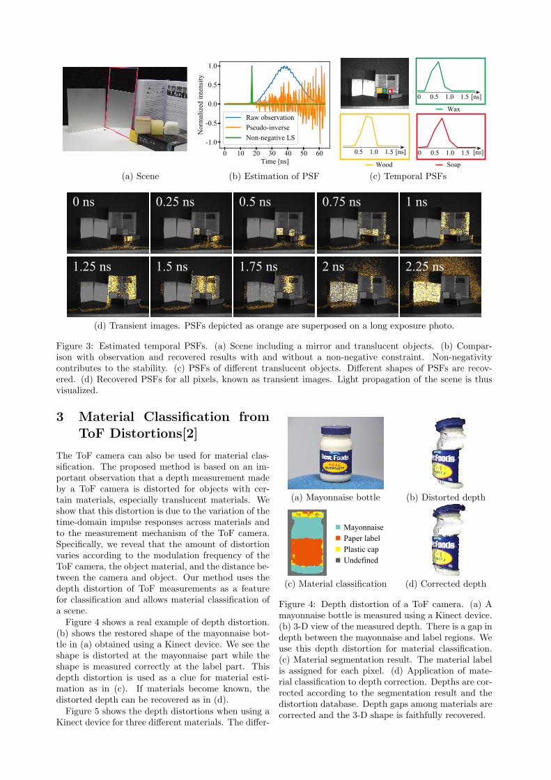
Recovering the temporal PSF is important for vari-ous applications, especially the analysis of light trans-port. Some methods that use amplitude-modulatedcontinuous-wave ToF cameras have been proposed torecover the temporal PSF, archiving resolution of sev-eral nanoseconds. In contrast, we show that sub-nanosecond resolution can be achieved using a pulsedToF camera and an additional delay circuit. Thedelay circuit is inserted before the illumination sothat the emission delay can be controlled on a sub-nanosecond scale as shown in Fig.2. We recover atemporal PSF of sub-nanosecond resolution from ob-servations for various delay settings.
Figure 3 shows the experimental results. (a) showsthe target scene, which includes a mirror and translu-cent objects. Strong interreflection and subsurfacescattering occur in this scene. (b) shows the observedreflection and recovered temporal PSF. (c) comparesthe recovered temporal PSFs of different translucentmaterials. (d) shows the recovered PSFs for all pixels,known as transient images. Light propagation of thescene is thus visualized.
(a)(b)
(c)
Figure 2: Experimental setting. (a) ToF camera. (b)light source. (c) delay circuit with a controller.
0 0.5 1.0 1.5 [ns]
0 0.5 1.0 1.5 [ns]
0 0.5 1.0 1.5 [ns]
Wood
Wax
Soap
(a) Scene (b) Estimation of PSF (c) Temporal PSFs
0 ns 0.25 ns 0.5 ns 0.75 ns 1 ns
1.25 ns 1.5 ns 1.75 ns 2 ns 2.25 ns
(d) Transient images. PSFs depicted as orange are superposed on a long exposure photo.
Figure 3: Estimated temporal PSFs. (a) Scene including a mirror and translucent objects. (b) Compar-ison with observation and recovered results with and without a non-negative constraint. Non-negativitycontributes to the stability. (c) PSFs of different translucent objects. Different shapes of PSFs are recov-ered. (d) Recovered PSFs for all pixels, known as transient images. Light propagation of the scene is thusvisualized.
3 Material Classification fromToF Distortions[2]
The ToF camera can also be used for material clas-sification. The proposed method is based on an im-portant observation that a depth measurement madeby a ToF camera is distorted for objects with cer-tain materials, especially translucent materials. Weshow that this distortion is due to the variation of thetime-domain impulse responses across materials andto the measurement mechanism of the ToF camera.Specifically, we reveal that the amount of distortionvaries according to the modulation frequency of theToF camera, the object material, and the distance be-tween the camera and object. Our method uses thedepth distortion of ToF measurements as a featurefor classification and allows material classification ofa scene.Figure 4 shows a real example of depth distortion.
(b) shows the restored shape of the mayonnaise bot-tle in (a) obtained using a Kinect device. We see theshape is distorted at the mayonnaise part while theshape is measured correctly at the label part. Thisdepth distortion is used as a clue for material esti-mation as in (c). If materials become known, thedistorted depth can be recovered as in (d).Figure 5 shows the depth distortions when using a
Kinect device for three different materials. The differ-
(a) Mayonnaise bottle (b) Distorted depth
MayonnaisePaper labelPlastic capUndefined
(c) Material classification (d) Corrected depth
Figure 4: Depth distortion of a ToF camera. (a) Amayonnaise bottle is measured using a Kinect device.(b) 3-D view of the measured depth. There is a gap indepth between the mayonnaise and label regions. Weuse this depth distortion for material classification.(c) Material segmentation result. The material labelis assigned for each pixel. (d) Application of mate-rial classification to depth correction. Depths are cor-rected according to the segmentation result and thedistortion database. Depth gaps among materials arecorrected and the 3-D shape is faithfully recovered.

(a) Acrylic board (b) Polystyrene board (c) Diffusion glass
Figure 5: Depth distortions measured using a Kinect device for three objects. The ground truth depth isobtained via a linear translation stage. The top row shows photographs of the target objects. Measurements ofthe second and third rows are different in terms of the surface orientation. Depth distortion at each frequencyvaries along with the actual depth and material. Depth distortion is similar for the same material regardlessof the surface orientation but largely different for different materials. This frequency- and depth-dependentdepth distortion is our important observation for material classification.
AluminumCopper
CeramicPlasterPaper
Flock paperNatural wood
CorkMedium density fiberboard
BambooCardboard
Cotton fabricFake leather
LeatherSynthetic fiber carpet
PolystyreneExpanded polyvinyl chloride
Rigid polyvinyl chlorideSilicone
PolypropyleneCoated acrylic board
White acryl 3mm thicknessWhite acryl 2mm thicknessWhite acryl 1mm thickness
Opal diffusion glassPolyurethane
0% 100%
Figure 6: Confusion matrix. Higher values of con-fusion are indicated red and appear on the diagonal.The overall accuracy is 90.5%.
ence in materials appears as depth distortion. We seethat depth distortion depends on not only the actualdepth but also the frequency of modulation.
We classified 26 different materials, includingmetal, wood, plastic, and fabric. Figure 6 shows theconfusion matrix. Higher values of confusion are in-dicated red and appears on the diagonal. The overallaccuracy is 90.5%.
Figure 7 shows the material segmentation resultsfor a white scene. It is difficult to classify the materialby eye or using a normal RGB camera because all ma-terials are white. However, pixels are independentlysegmented for each material without using shape in-formation.
4 Conclusion
This paper introduced an unusual use of the ToF cam-era. Depth sensing is of course important for under-
CeramicPlastic (PP) Plastic (PS)FabricFabric
Plastic (PP)
Ceramic
Plas
tic (P
S)
Figure 7: Left: Material segmentation results for awhite scene. All utensils are white and classificationis thus difficult using only with an RGB image. Right:The result of material classification. Although thereis estimation error due to the pixel-wise processingand there being only one depth variation, the sceneis much more interpretable than in the RGB image.
standing a scene but the light transport also has richoptical information of the scene. We are attemptingto develop new functions of the ToF camera so thatit becomes a new tool in the field of computer vision.AcknowledgmentThese works have been supported by JST CRESTJPMJCR1764.
References
[1] K. Kitano, T. Okamoto, K. Tanaka, T. Aoto, H.Kubo, T. Funatomi, Y. Mukaigawa, “RecoveringTemporal PSF using ToF Camera with DelayedLight Emission”, IPSJ Transactions on ComputerVision and Applications, June 2017.
[2] K. Tanaka, Y. Mukaigawa, T. Funatomi, H. Kubo,Y. Matsushita, Y. Yagi, “Material Classificationfrom Time-of-Flight Distortions”, IEEE Trans. onPattern Analysis and Machine Intelligence, Sep.2018.
Related Documents