Installation, use and maintenance instructions Light Oil Burners RL 70/M - 100/M - 130/M Low - High or Modulating Operation C6505053 - 2916050 (3) - 10/2008

Welcome message from author
This document is posted to help you gain knowledge. Please leave a comment to let me know what you think about it! Share it to your friends and learn new things together.
Transcript

Installation, use and maintenance instructions
Light Oil Burners
RL 70/M - 100/M - 130/M
Low - High or Modulating Operation
C6505053 - 2916050 (3) - 10/2008

2
CONTENTS
TECHNICAL DATA . . . . . . . . . . . . . . . . . . . . . . . . . . . . . . .page 3Burner models designations. . . . . . . . . . . . . . . . . . . . . . . . . . . . . 3Accessories . . . . . . . . . . . . . . . . . . . . . . . . . . . . . . . . . . . . . . . . . 3Burner description . . . . . . . . . . . . . . . . . . . . . . . . . . . . . . . . . . . . 4Packaging - Weight . . . . . . . . . . . . . . . . . . . . . . . . . . . . . . . . . . . 4Max. dimensions . . . . . . . . . . . . . . . . . . . . . . . . . . . . . . . . . . . . . 4Standard equipment . . . . . . . . . . . . . . . . . . . . . . . . . . . . . . . . . . . 4Firing rates . . . . . . . . . . . . . . . . . . . . . . . . . . . . . . . . . . . . . . . . . . 5Minimum furnace dimensions. . . . . . . . . . . . . . . . . . . . . . . . . . . . 5
INSTALLATION . . . . . . . . . . . . . . . . . . . . . . . . . . . . . . . . . . . . . . 6Boiler plate . . . . . . . . . . . . . . . . . . . . . . . . . . . . . . . . . . . . . . . . . . 6Blast tube length . . . . . . . . . . . . . . . . . . . . . . . . . . . . . . . . . . . . . 6Securing the burner to the boiler . . . . . . . . . . . . . . . . . . . . . . . . . 6Choice of nozzle. . . . . . . . . . . . . . . . . . . . . . . . . . . . . . . . . . . . . . 7Nozzle assembly . . . . . . . . . . . . . . . . . . . . . . . . . . . . . . . . . . . . . 7Combustion head setting . . . . . . . . . . . . . . . . . . . . . . . . . . . . . . . 7Fuel supply . . . . . . . . . . . . . . . . . . . . . . . . . . . . . . . . . . . . . . . . . . 8Hydraulic connections . . . . . . . . . . . . . . . . . . . . . . . . . . . . . . . . . 8Pump . . . . . . . . . . . . . . . . . . . . . . . . . . . . . . . . . . . . . . . . . . . . . . 9Air pressure switch . . . . . . . . . . . . . . . . . . . . . . . . . . . . . . . . . . . . 9Servomotor. . . . . . . . . . . . . . . . . . . . . . . . . . . . . . . . . . . . . . . . . 10Burner calibration . . . . . . . . . . . . . . . . . . . . . . . . . . . . . . . . . . . . .11Burner starting . . . . . . . . . . . . . . . . . . . . . . . . . . . . . . . . . . . . . . 12Burner operation. . . . . . . . . . . . . . . . . . . . . . . . . . . . . . . . . . . . . 13Oil pressure switch . . . . . . . . . . . . . . . . . . . . . . . . . . . . . . . . . . . 13Final checks . . . . . . . . . . . . . . . . . . . . . . . . . . . . . . . . . . . . . . . . 14Maintenance. . . . . . . . . . . . . . . . . . . . . . . . . . . . . . . . . . . . . . . . 14Procedure to refer burner operating conditionin high altitude plants . . . . . . . . . . . . . . . . . . . . . . . . . . . . . . 15Flame signal measurements . . . . . . . . . . . . . . . . . . . . . . . . . . . 16Siemens LAL control sequence of operations . . . . . . . . . . . . . . 16Siemens LAL control troubleshooting guide. . . . . . . . . . . . . . . . 17Factory wiring diagram - burner mounted LAL . . . . . . . . . . . . . . 18Field wiring diagram- burner mounted LAL . . . . . . . . . . . . . . . . 19Factory wiring diagram - remote panel . . . . . . . . . . . . . . . . . . . . 20Spare parts list . . . . . . . . . . . . . . . . . . . . . . . . . . . . . . . . . . . 23Start up reports . . . . . . . . . . . . . . . . . . . . . . . . . . . . . . . . . . . . . . 27
N.B.Figures mentioned in the text are identified as follows:1)(A) =part 1 of figure A, same page as text;1)(A)p.4 =part 1 of figure A, page number 4.
WARNING
Do not store flammable or hazardous materials in the vicinity of fuel burning appliances.
Improper installation, adjustment, alteration, service or main-tenance can cause property damage, personal injury or death. Refer to this manual for instructional or additional in-formation. Consult a certified installer, service representative or the gas supplier for further assistance.
Burner shall be installed in accordance with manufacturers requirements as outlined in this manual, local codes and au-thorities having jurisdiction.
3
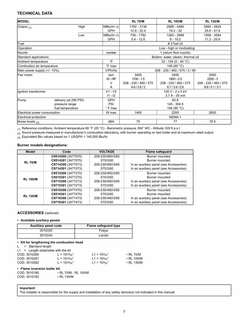
TECHNICAL DATA
(1) Reference conditions: Ambient temperature 68 °F (20 °C) - Barometric pressure 394” WC - Altitude 329 ft a.s.l.(2) Sound pressure measured in manufacturer’s combustion laboratory, with burner operating on test boiler and at maximum rated output.(3) Equivalent Btu values based on 1 USGPH = 140,000 Btu/hr.
Burner models designations:
ACCESSORIES (optional):
• Available auxiliary panels
• Kit for lengthening the combustion headL = Standard lengthL1 = Length obtainable with the kitCOD. 3010280 L = 1023/32” L1 = 155/32” • RL 70/MCOD. 3010281 L = 1023/32” L1 = 155/32” • RL 100/MCOD. 3010282 L = 1023/32” L1 = 155/32” • RL 130/M
• Flame inversion boiler kitCOD. 3010180 • RL 70/M - RL 100/MCOD. 3010183 • RL 130/M
MODEL RL 70/M RL 100/M RL 130/MOutput (1) High MBtu/hr (3)
GPH1792 - 313612.8 - 22.4
2688 - 448019.2 - 32
3564 - 582425.6 - 41.6
Low MBtu/hr (3)GPH
756 - 17925.4 - 12.8
1260 - 26889 - 19.2
1568 - 358411.2 - 25.6
Fuel # 2 fuel oilOperation Low - high or modulatingNozzle number 1 (return flow nozzle)Standard applications Boilers: water, steam, thermal oilAmbient temperature °F 32 - 104 (0 - 40 °C)Combustion air temperature °F max 140 (60 °C)Main power supply (+/- 10%) V/Ph/Hz 208 - 230 / 460 / 575 / 3 / 60Fan motor rpm
W - HPVA
34001100 - 1.5
208 - 230 / 460 / 5754.8 / 2.8 / 2
34001800 - 2.5
208 - 230 / 460 / 5756.7 / 3.9 / 2.8
34002200 - 3
208 - 230 / 460 / 5758.8 / 5.1 / 3.7
Ignition transformer V1 - V2I1 - I2
120 V - 2 x 5 kV3.7 A - 35 mA
Pump delivery (at 290 PSI)pressure rangefuel temperature
GPHPSI
° F max
60.8145 - 304.5194 (90 °C)
Electrical power consumption W max 1400 2200 2600Electrical protection NEMA 1Noise levels (2) dBA 75 77 78.5
Model Code VOLTAGE Flame safeguard
RL 70/M
C9514300 (3477070)C9514301 (3477075)C9714300 (3477073)C9714301 (3477073)
208-230/460/3/60575/3/60
208-230/460/3/60575/3/60
Burner mountedBurner mounted
In an auxiliary panel (see Accessories)In an auxiliary panel (see Accessories)
RL 100/M
C9515300 (3477270)C9515301 (3477275)C9715300 (3477273)C9715301 (3477273)
208-230/460/3/60575/3/60
208-230/460/3/60575/3/60
Burner mountedBurner mounted
In an auxiliary panel (see Accessories)In an auxiliary panel (see Accessories)
RL 130/M
C9516300 (3477470)C9516301 (3477475)C9716300 (3477473)C9716301 (3477473)
208-230/460/3/60575/3/60
208-230/460/3/60575/3/60
Burner mountedBurner mounted
In an auxiliary panel (see Accessories)In an auxiliary panel (see Accessories)
Auxiliary panel code Flame safeguard type3010330 Fireye3010334 Landis
Important:The installer is responsible for the supply and installation of any safety device(s) not indicated in this manual.

4
BURNER DESCRIPTION (A)1 Ignition electrodes2 Combustion head3 Screw for combustion head adjustment4 Screw for fixing fan to flange5 Pressure gauge for pressure on nozzle return6 Pump7 Non-drip nozzle holder8 Air damper9 Fan pressure test point 10 Boiler mounting flange11 Flame stability disk12 Servomotor, provides adjustment of fuel delivery reg-
ulator and of air damper.When the burner is not operating the air damper isfully closed in order to reduce to a minimum heat dis-persion from the boiler.
13 Slide bars for opening the burner and inspecting thecombustion head
14 Photocell (cad cell)15 High oil pressure switch16 Extensions for slide bars 14) (with kit)17 Ignition transformer18 Motor contactor and thermal overload with reset but-
ton19 Power switch for different operations:
automatic - manual - off.Button for:power increase - power reduction.
20 Valve assembly with pressure regulator on nozzlereturn
21 Terminal strip22 Knockouts for electrical connections by installer23 Flame safeguard with lock-out pilot light and lock-out
reset button24 Flame inspection window
Two types of burner failure may occur:
Flame safeguard Lock-out: if the Flame relay 23)(A)pushbutton lights up, it indicates that the burner is inlock-out.To reset, press the pushbutton.Motor trip: release by pressing the pushbutton on ther-mal overload 18)(A).
PACKAGING - WEIGHT (B) - Approximate meas-urements• The burners is supplied skid mounted. Outer dimen-sions of packaging are indicated in (B).• The weight of the burner complete with packaging isindicated in Table (B).
MAX. DIMENSIONS (C) - Approximate measure-mentsThe maximum dimensions of the burners are given in(C).Keep in mind that inspection of the combustion headrequires the burner to be opened and the rear part with-drawn on the slide bars.The maximum dimension of the burner when open, with-out casing, is given in measurement I.
STANDARD EQUIPMENT2 - Flexible hoses2 - Gaskets for flexible hoses1 - Burner head gasket4 - Screws to secure the burner flange to the boiler
1/2 W1 - Adaptor G 1/8“ / 1/8“ NPT1 - Instruction booklet1 - Spare parts list
(A)
inch A B C lbsRL 70/M 459/32“ 235/8“ 313/16“ 143RL 100/M 459/32“ 235/8“ 313/16“ 150RL 130/M 459/32“ 235/8“ 313/16“ 157
(B)
(C)
D2349
D36
D1217
(1) Blast tube: short - long (obtainable with the kit)
RL A B C D E F (1) G H I (1)70 261/8” 1121/32” 1415/32” 2127/32” 2625/32” 1023/32” - 155/32” 71/16” 1615/16” 377/16” - 423/4”
100 261/8” 129/32” 1415/32” 2127/32” 2625/32” 1023/32” - 155/32” 71/16” 1615/16” 377/16” - 423/4”130 273/4” 135/16” 1415/32” 2127/32” 2625/32” 1023/32” - 155/32” 77/16” 1615/16” 377/16” - 423/4”
5
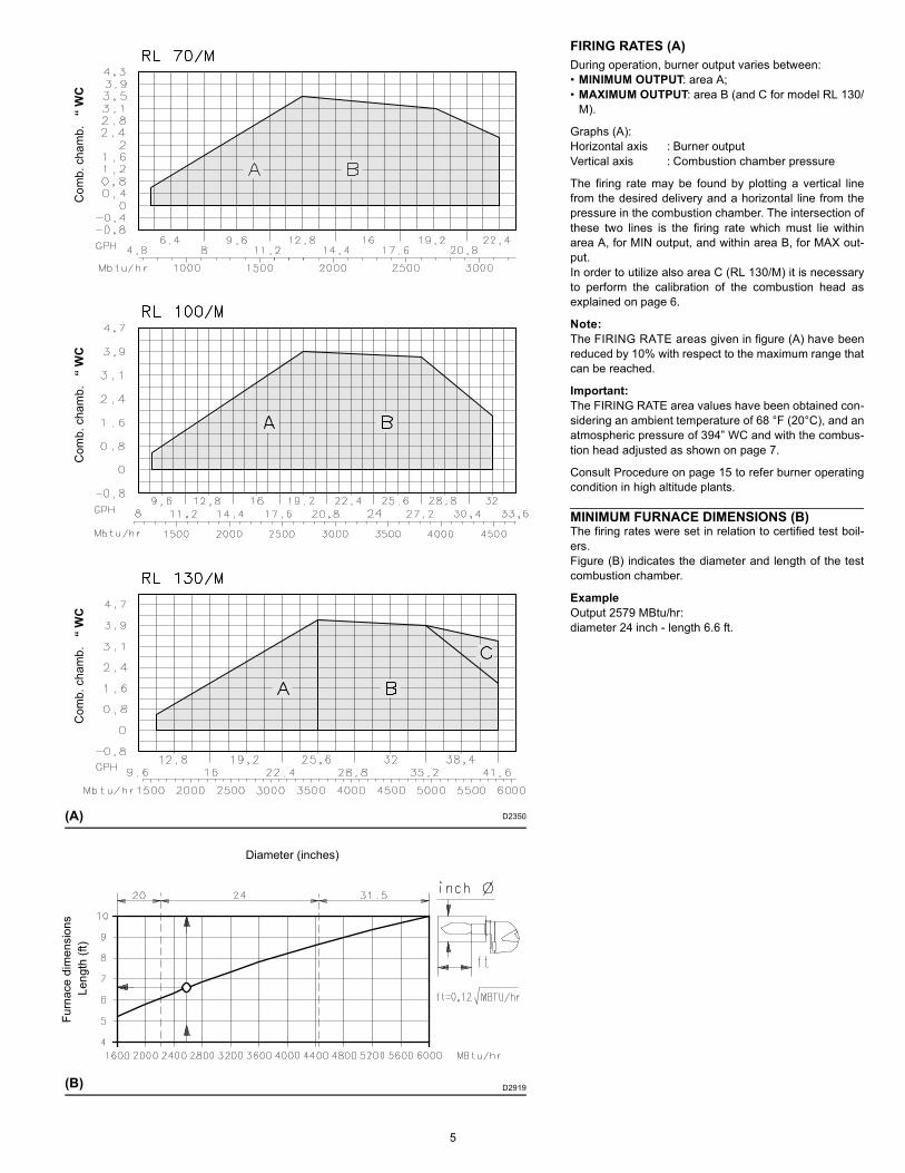
FIRING RATES (A)During operation, burner output varies between:• MINIMUM OUTPUT: area A;• MAXIMUM OUTPUT: area B (and C for model RL 130/
M).
Graphs (A):Horizontal axis : Burner outputVertical axis : Combustion chamber pressure
The firing rate may be found by plotting a vertical linefrom the desired delivery and a horizontal line from thepressure in the combustion chamber. The intersection ofthese two lines is the firing rate which must lie withinarea A, for MIN output, and within area B, for MAX out-put.In order to utilize also area C (RL 130/M) it is necessaryto perform the calibration of the combustion head asexplained on page 6.
Note: The FIRING RATE areas given in figure (A) have beenreduced by 10% with respect to the maximum range thatcan be reached.
Important: The FIRING RATE area values have been obtained con-sidering an ambient temperature of 68 °F (20°C), and anatmospheric pressure of 394” WC and with the combus-tion head adjusted as shown on page 7.
Consult Procedure on page 15 to refer burner operatingcondition in high altitude plants.
MINIMUM FURNACE DIMENSIONS (B)The firing rates were set in relation to certified test boil-ers. Figure (B) indicates the diameter and length of the testcombustion chamber.
ExampleOutput 2579 MBtu/hr:diameter 24 inch - length 6.6 ft.
(A) D2350
(B)
Com
b. c
ham
b.
“ W
CC
omb.
cha
mb.
“
WC
Com
b. c
ham
b.
“ W
C
D2919
Diameter (inches)
Leng
th (f
t)Fu
rnac
e di
men
sion
s
6
INSTALLATION
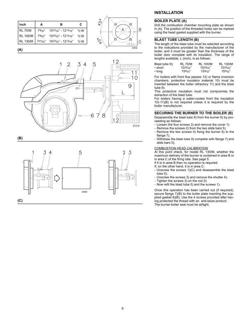
BOILER PLATE (A) Drill the combustion chamber mounting plate as shownin (A). The position of the threaded holes can be markedusing the head gasket supplied with the burner.
BLAST TUBE LENGTH (B) The length of the blast tube must be selected accordingto the indications provided by the manufacturer of theboiler, and it must be greater than the thickness of theboiler door complete with its insulation. The range oflengths available, L (inch), is as follows:
Blast tube 9): RL 70/M RL 100/M RL 130/M• short 1023/32” 1023/32” 1023/32”• long 155/32” 155/32” 155/32”
For boilers with front flue passes 12) or flame inversionchambers, protective insulaton material 10) must beinserted between the boiler refractory 11) and the blasttube 9).This protective insulation must not compromise theextraction of the blast tube.For boilers having a water-cooled front the insulation10)-11)(B) is not required unless it is required by theboiler manufacturer.
SECURING THE BURNER TO THE BOILER (B) Disassemble the blast tube 9) from the burner 6) by pro-ceeding as follows:- Loosen the four screws 3) and remove the cover 1).- Remove the screws 2) from the two slide bars 5).- Remove the two screws 4) fixing the burner 6) to the
flange 7).- Withdraw the blast tube 9) complete with flange 7) and
slide bars 5).
COMBUSTION HEAD CALIBRATIONAt this point check, for model RL 130/M, whether themaximum delivery of the burner is contained in area B orin area C of the firing rate. See page 5.If it is in area B then no operation is required.If, on the other hand, it is in area C:- Unscrew the screws 1)(C) and disassemble the blast
tube 5);- Unscrew the screws 3) and remove the shutter 4);- Tighten the screws 3) on the rod 2);- Now refit the blast tube 5) and the screws 1).
Once this operation has been carried out (if required),secure flange 7)(B) to the boiler plate inserting the sup-plied gasket 8)(B). Use the 4 screws provided after hav-ing protected the thread with an anti-seize product.The burner-boiler seal must be airtight.
(C)
D455
(B)
(A)
inch A B C
RL 70/M 79/32“ 1027/32“ - 1213/16“ 1/2 WRL 100/M 79/32“ 1027/32“ - 1213/16“ 1/2 WRL 130/M 721/32“ 1027/32“ - 1213/16“ 1/2 W
D1219
D690
7
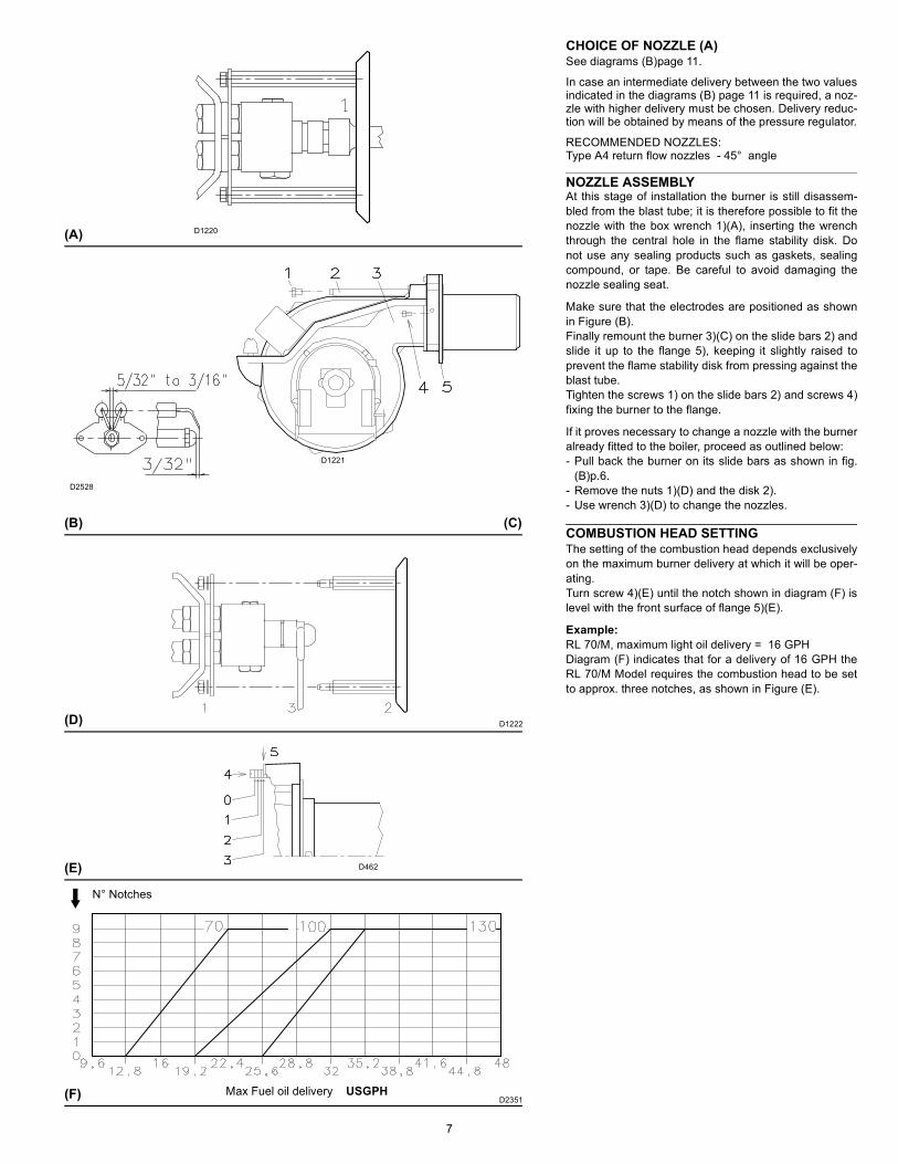
CHOICE OF NOZZLE (A)See diagrams (B)page 11.
In case an intermediate delivery between the two valuesindicated in the diagrams (B) page 11 is required, a noz-zle with higher delivery must be chosen. Delivery reduc-tion will be obtained by means of the pressure regulator.
RECOMMENDED NOZZLES:Type A4 return flow nozzles - 45° angle
NOZZLE ASSEMBLYAt this stage of installation the burner is still disassem-bled from the blast tube; it is therefore possible to fit thenozzle with the box wrench 1)(A), inserting the wrenchthrough the central hole in the flame stability disk. Donot use any sealing products such as gaskets, sealingcompound, or tape. Be careful to avoid damaging thenozzle sealing seat.
Make sure that the electrodes are positioned as shownin Figure (B).Finally remount the burner 3)(C) on the slide bars 2) andslide it up to the flange 5), keeping it slightly raised toprevent the flame stability disk from pressing against theblast tube.Tighten the screws 1) on the slide bars 2) and screws 4)fixing the burner to the flange.
If it proves necessary to change a nozzle with the burneralready fitted to the boiler, proceed as outlined below:- Pull back the burner on its slide bars as shown in fig.
(B)p.6.- Remove the nuts 1)(D) and the disk 2).- Use wrench 3)(D) to change the nozzles.
COMBUSTION HEAD SETTINGThe setting of the combustion head depends exclusivelyon the maximum burner delivery at which it will be oper-ating.Turn screw 4)(E) until the notch shown in diagram (F) islevel with the front surface of flange 5)(E).
Example:RL 70/M, maximum light oil delivery = 16 GPHDiagram (F) indicates that for a delivery of 16 GPH theRL 70/M Model requires the combustion head to be setto approx. three notches, as shown in Figure (E).
(D)
(B)
(A) D1220
D1221
(C)
D1222
D462(E)
N° Notches
Max Fuel oil delivery USGPHD2351(F)
D2528
8
HYDRAULIC SYSTEM
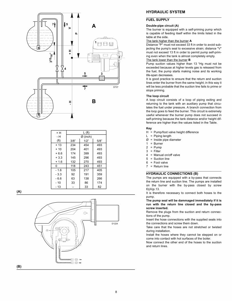
FUEL SUPPLYDouble-pipe circuit (A)The burner is equipped with a self-priming pump whichis capable of feeding itself within the limits listed in thetable at the side. The tank higher than the burner ADistance "P" must not exceed 33 ft in order to avoid sub-jecting the pump's seal to excessive strain; distance "V"must not exceed 13 ft in order to permit pump self-prim-ing even when the tank is almost completely empty.The tank lower than the burner BPump suction values higher than 13 “Hg must not beexceeded because at higher levels gas is released fromthe fuel, the pump starts making noise and its workinglife-span decreases.It is good practice to ensure that the return and suctionlines enter the burner from the same height; in this way itwill be less probable that the suction line fails to prime orstops priming.
The loop circuitA loop circuit consists of a loop of piping exiting andreturning to the tank with an auxiliary pump that circu-lates the fuel under pressure. A branch connection fromthe loop goes to feed the burner. This circuit is extremelyuseful whenever the burner pump does not succeed inself-priming because the tank distance and/or height dif-ference are higher than the values listed in the Table.
KeyH = Pump/foot valve height differenceL = Piping lengthØ = Inside pipe diameter1 = Burner2 = Pump3 = Filter4 = Manual on/off valve5 = Suction line6 = Foot valve7 = Return line
HYDRAULIC CONNECTIONS (B)The pumps are equipped with a by-pass that connectsthe return line and suction line. The pumps are installedon the burner with the by-pass closed by screw6)(A)p.13.It is therefore necessary to connect both hoses to thepump.The pump seal will be dammaged immediately if it isrun with the return line closed and the by-passscrew inserted.Remove the plugs from the suction and return connec-tions of the pump.Insert the hose connections with the supplied seals intothe connections and screw them down. Take care that the hoses are not stretched or twistedduring installation.Install the hoses where they cannot be stepped on orcome into contact with hot surfaces of the boiler.Now connect the other end of the hoses to the suctionand return lines.
(B)
(A)
+ H- H(ft)
L (ft)Ø (inch)
3/8” 1/2” 5/8”+ 13 234 454 493+ 10 204 401 493+ 6.6 174 399 493+ 3.3 145 296 493+ 1.6 132 270 4930 118 243 451- 1.6 105 217 405- 3.3 92 191 359- 6.6 63 138 266- 10 33 86 174- 13 – 33 82
A
B
1
2
3
7
5
6
6
4
7 5
- H+
HV
P
D737
D1224
315 /
16”
9
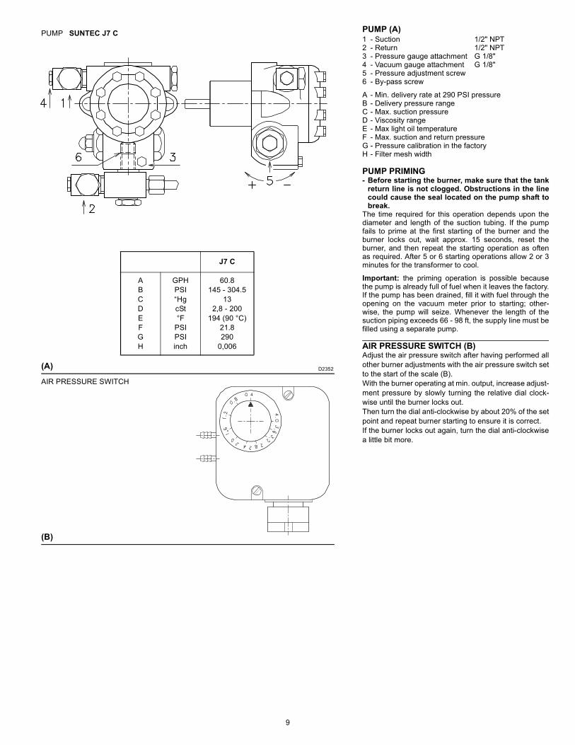
PUMP (A)1 - Suction 1/2" NPT2 - Return 1/2" NPT3 - Pressure gauge attachment G 1/8"4 - Vacuum gauge attachment G 1/8"5 - Pressure adjustment screw6 - By-pass screw
A - Min. delivery rate at 290 PSI pressureB - Delivery pressure rangeC - Max. suction pressureD - Viscosity rangeE - Max light oil temperatureF - Max. suction and return pressureG - Pressure calibration in the factoryH - Filter mesh width
PUMP PRIMING- Before starting the burner, make sure that the tank
return line is not clogged. Obstructions in the linecould cause the seal located on the pump shaft tobreak.
The time required for this operation depends upon thediameter and length of the suction tubing. If the pumpfails to prime at the first starting of the burner and theburner locks out, wait approx. 15 seconds, reset theburner, and then repeat the starting operation as oftenas required. After 5 or 6 starting operations allow 2 or 3minutes for the transformer to cool.
Important: the priming operation is possible becausethe pump is already full of fuel when it leaves the factory.If the pump has been drained, fill it with fuel through theopening on the vacuum meter prior to starting; other-wise, the pump will seize. Whenever the length of thesuction piping exceeds 66 - 98 ft, the supply line must befilled using a separate pump.
AIR PRESSURE SWITCH (B)Adjust the air pressure switch after having performed allother burner adjustments with the air pressure switch setto the start of the scale (B).With the burner operating at min. output, increase adjust-ment pressure by slowly turning the relative dial clock-wise until the burner locks out.Then turn the dial anti-clockwise by about 20% of the setpoint and repeat burner starting to ensure it is correct.If the burner locks out again, turn the dial anti-clockwisea little bit more.
(A)
PUMP SUNTEC J7 C
D2352
J7 C
ABCDEFGH
GPHPSI“HgcSt°F
PSIPSIinch
60.8145 - 304.5
132,8 - 200
194 (90 °C)21.8290
0,006
(B)
AIR PRESSURE SWITCH
10
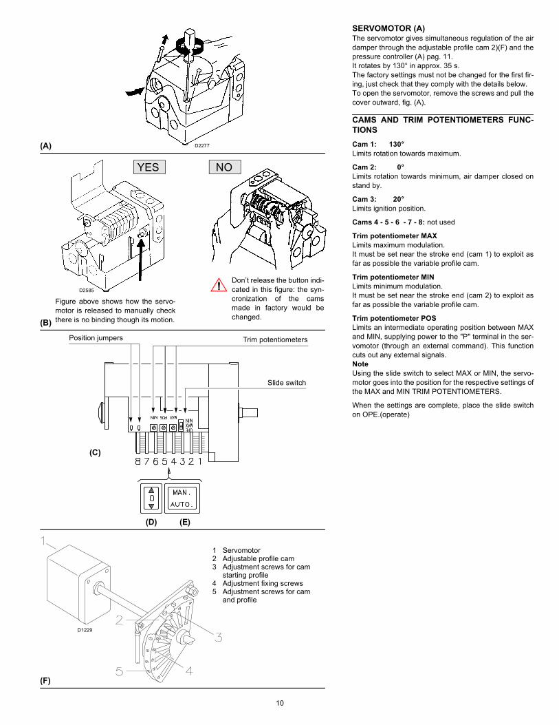
SERVOMOTOR (A)The servomotor gives simultaneous regulation of the airdamper through the adjustable profile cam 2)(F) and thepressure controller (A) pag. 11.It rotates by 130° in approx. 35 s.The factory settings must not be changed for the first fir-ing, just check that they comply with the details below.To open the servomotor, remove the screws and pull thecover outward, fig. (A).
CAMS AND TRIM POTENTIOMETERS FUNC-TIONSCam 1: 130° Limits rotation towards maximum.
Cam 2: 0° Limits rotation towards minimum, air damper closed onstand by.
Cam 3: 20° Limits ignition position.
Cams 4 - 5 - 6 - 7 - 8: not used
Trim potentiometer MAXLimits maximum modulation.It must be set near the stroke end (cam 1) to exploit asfar as possible the variable profile cam.
Trim potentiometer MINLimits minimum modulation.It must be set near the stroke end (cam 2) to exploit asfar as possible the variable profile cam.
Trim potentiometer POSLimits an intermediate operating position between MAXand MIN, supplying power to the "P" terminal in the ser-vomotor (through an external command). This functioncuts out any external signals.NoteUsing the slide switch to select MAX or MIN, the servo-motor goes into the position for the respective settings ofthe MAX and MIN TRIM POTENTIOMETERS.
When the settings are complete, place the slide switchon OPE.(operate)
(A)
(D)
(F)
D2277
(E)
1 Servomotor2 Adjustable profile cam3 Adjustment screws for cam
starting profile4 Adjustment fixing screws5 Adjustment screws for cam
and profile
D1229
(B)
D2585
NO
Figure above shows how the servo-motor is released to manually checkthere is no binding though its motion.
Don’t release the button indi-cated in this figure: the syn-cronization of the camsmade in factory would bechanged.
YES
(C)
Slide switch
Trim potentiometersPosition jumpers
11
BURNER CALIBRATIONThe optimum calibration of the burner requires an analy-sis of the flue gases at the boiler outlet.The following settings that have already been made donot require modification under normal circumstances:• Combustion head;• Servomotor, cams I - II - III
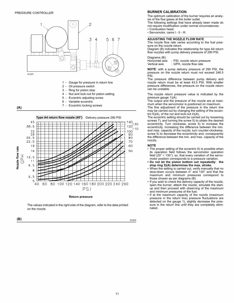
ADJUSTING THE NOZZLE FLOW RATEThe nozzle flow rate varies according to the fuel pres-sure on the nozzle return.Diagram (B) indicates this relationship for type A4 returnflow nozzles with pump delivery pressure of 290 PSI.
Diagrams (B):Horizontal axis : PSI, nozzle return pressureVertical axis : GPH, nozzle flow rate
NOTE: with a pump delivery pressure of 290 PSI, thepressure on the nozzle return must not exceed 246.5PSI.The pressure difference between pump delivery andnozzle return must be at least 43.5 PSI. With smallerpressure differences, the pressure on the nozzle returncan be unstable.
The nozzle return pressure value is indicated by thepressure gauge 1)(A).The output and the pressure of the nozzle are at maxi-mum when the servomotor is positioned on maximum.The fine adjustment of the pressure in the return linemay be carried out by changing the setting of the eccen-tric 6)(A), of the nut and lock-nut 4)(A).The eccentric setting should be carried out by looseningscrews 7), and turning the screw 5) to obtain the desiredeccentricity. Turn clockwise, screw 5) to increase theeccentricity, increasing the difference between the min.and max. capacity of the nozzle; turn counter-clockwise,screw 5) to decrease the eccentricity and, consequentlythe difference between the min. and max. capacity of thenozzle.
NOTE• The proper setting of the eccentric 6) is possible when
its operation field follows the servomotor operationfield (20° ÷ 130°): so, that every variation of the servo-motor position corresponds to a pressure variation.
• Do not let the piston bottom out repeatedly: thestop ring 3)(A) determines the max. stroke.
• When the setting is carried out, verify manually that noslow-down occurs between 0° and 130° and that themaximum and minimum pressures correspond tothose chosen as per diagrams (B).
• If you wish to check the delivery capacity of the nozzle,open the burner, attach the nozzle, simulate the start-up and then proceed with observing of the maximumand minimum pressures of the fuel.
• If at the maximum capacity of the nozzle (maximumpressure in the return line) pressure fluctuations aredetected on the gauge 1), slightly decrease the pres-sure in the return line until they are completely elimi-nated.
D1227
(A)
1 - Gauge for pressure in return line2 - Oil pressure switch3 - Ring for piston stop4 - Nut and lock-nut for piston setting5 - Eccentric adjusting screw6 - Variable eccentric7 - Eccentric locking screws
PRESSURE CONTROLLER
D2355(B)
Noz
zle
flow
rate
Return pressure
Delivery pressure 290 PSIType A4 return flow nozzle (45°)
The values indicated in the right side of the diagram, refer to the data printed on the nozzle.
12
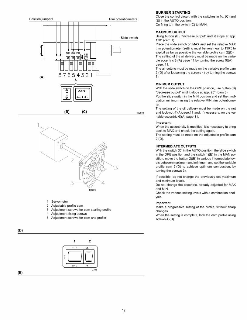
BURNER STARTINGClose the control circuit, with the switches in fig. (C) and(E) in the AUTO position.On firing turn the switch (C) to MAN.
MAXIMUM OUTPUTUsing button (B), "increase output" until it stops at app.130° (cam 1).Place the slide switch on MAX and set the relative MAXtrim potentiometer (setting must be very near to 130°) toexploit as far as possible the variable profile cam 2)(D).The setting of the oil delivery must be made on the varia-ble eccentric 6)(A) page 11 by turning the screw 5)(A)page. 11.The air setting must be made on the variable profile cam2)(D) after loosening the screws 4) by turning the screws3).
MINIMUM OUTPUTWith the slide switch on the OPE position, use button (B)"decrease output" until it stops at app. 20° (cam 3).Put the slide switch in the MIN position and set the mod-ulation minimum using the relative MIN trim potentiome-ter.The setting of the oil delivery must be made on the nutand lock-nut 4)(A)page.11 and, if necessary, on the va-riable eccentric 6)(A) page 11.
ImportantWhen the eccentricity is modified, it is necessary to bringback to MAX and check the setting again.The setting must be made on the adjustable profile cam2)(D).
INTERMEDIATE OUTPUTSWith the switch (C) in the AUTO position, the slide switchin the OPE position and the switch 1)(E) in the MAN po-sition, move the button 2)(E) in various intermediate lev-els between maximum and minimum and set the variableprofile cam 2)(D) to achieve optimum combustion, byturning the screws 3).
If possible, do not change the previously set maximumand minimum levels.Do not change the eccentric, already adjusted for MAXand MIN.Check the various setting levels with a combustion anal-ysis.
ImportantMake a progressive setting of the profile, without sharpchanges.When the setting is complete, lock the cam profile usingscrews 4)(D).
(E)
1 2
D791
(B) (C)
(D)
1 Servomotor2 Adjustable profile cam3 Adjustment screws for cam starting profile4 Adjustment fixing screws5 Adjustment screws for cam and profile
(A)
Slide switch
Trim potentiometersPosition jumpers
D1229
D2593
13
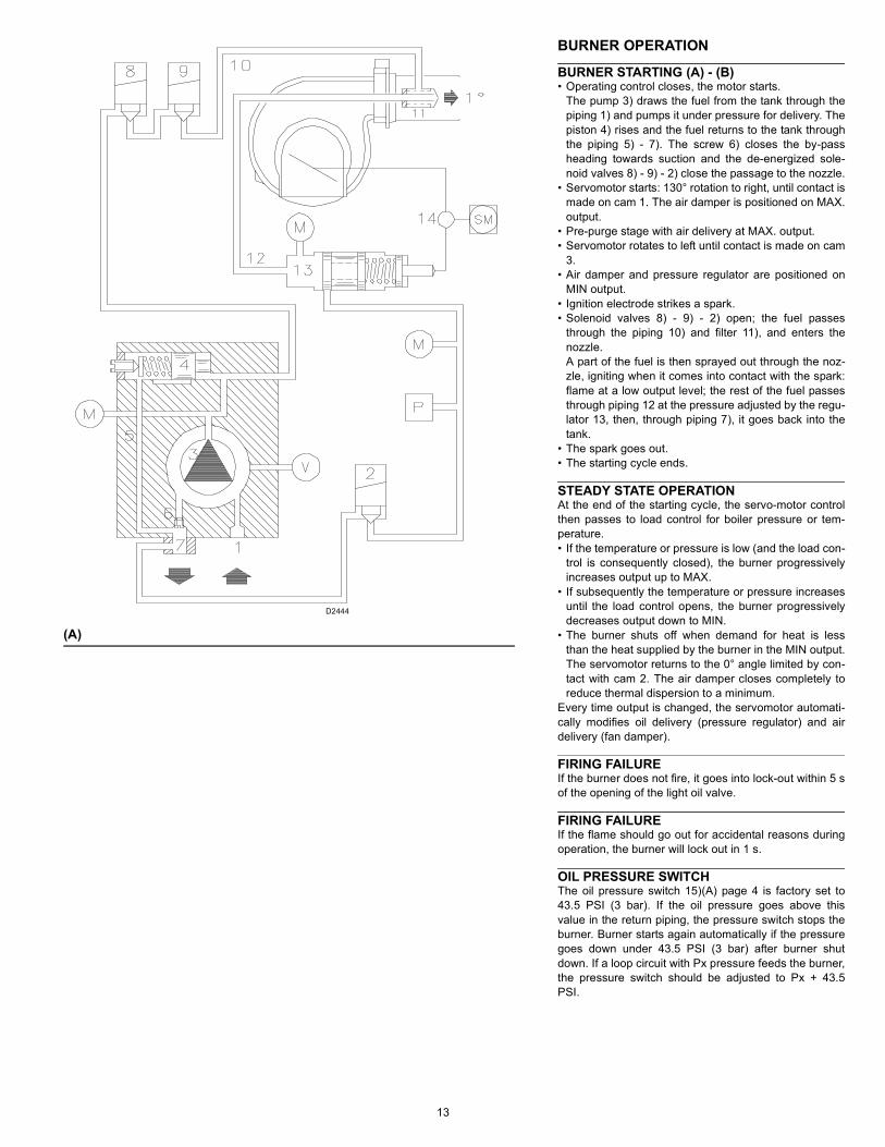
BURNER OPERATION
BURNER STARTING (A) - (B)• Operating control closes, the motor starts.
The pump 3) draws the fuel from the tank through thepiping 1) and pumps it under pressure for delivery. Thepiston 4) rises and the fuel returns to the tank throughthe piping 5) - 7). The screw 6) closes the by-passheading towards suction and the de-energized sole-noid valves 8) - 9) - 2) close the passage to the nozzle.
• Servomotor starts: 130° rotation to right, until contact ismade on cam 1. The air damper is positioned on MAX.output.
• Pre-purge stage with air delivery at MAX. output.• Servomotor rotates to left until contact is made on cam
3.• Air damper and pressure regulator are positioned on
MIN output.• Ignition electrode strikes a spark.• Solenoid valves 8) - 9) - 2) open; the fuel passes
through the piping 10) and filter 11), and enters thenozzle.A part of the fuel is then sprayed out through the noz-zle, igniting when it comes into contact with the spark:flame at a low output level; the rest of the fuel passesthrough piping 12 at the pressure adjusted by the regu-lator 13, then, through piping 7), it goes back into thetank.
• The spark goes out.• The starting cycle ends.
STEADY STATE OPERATIONAt the end of the starting cycle, the servo-motor controlthen passes to load control for boiler pressure or tem-perature.• If the temperature or pressure is low (and the load con-
trol is consequently closed), the burner progressivelyincreases output up to MAX.
• If subsequently the temperature or pressure increasesuntil the load control opens, the burner progressivelydecreases output down to MIN.
• The burner shuts off when demand for heat is lessthan the heat supplied by the burner in the MIN output.The servomotor returns to the 0° angle limited by con-tact with cam 2. The air damper closes completely toreduce thermal dispersion to a minimum.
Every time output is changed, the servomotor automati-cally modifies oil delivery (pressure regulator) and airdelivery (fan damper).
FIRING FAILUREIf the burner does not fire, it goes into lock-out within 5 sof the opening of the light oil valve.
FIRING FAILUREIf the flame should go out for accidental reasons duringoperation, the burner will lock out in 1 s.
OIL PRESSURE SWITCHThe oil pressure switch 15)(A) page 4 is factory set to43.5 PSI (3 bar). If the oil pressure goes above thisvalue in the return piping, the pressure switch stops theburner. Burner starts again automatically if the pressuregoes down under 43.5 PSI (3 bar) after burner shutdown. If a loop circuit with Px pressure feeds the burner,the pressure switch should be adjusted to Px + 43.5PSI.
(A)
D2444
14
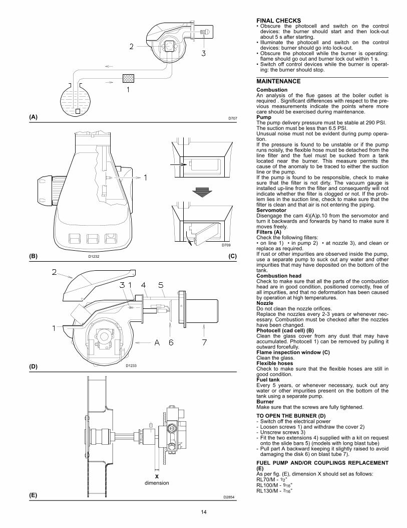
FINAL CHECKS• Obscure the photocell and switch on the control
devices: the burner should start and then lock-outabout 5 s after starting.
• Illuminate the photocell and switch on the controldevices: burner should go into lock-out.
• Obscure the photocell while the burner is operating:flame should go out and burner lock out within 1 s.
• Switch off control devices while the burner is operat-ing: the burner should stop.
MAINTENANCECombustionAn analysis of the flue gases at the boiler outlet isrequired . Significant differences with respect to the pre-vious measurements indicate the points where morecare should be exercised during maintenance.PumpThe pump delivery pressure must be stable at 290 PSI.The suction must be less than 6.5 PSI.Unusual noise must not be evident during pump opera-tion.If the pressure is found to be unstable or if the pumpruns noisily, the flexible hose must be detached from theline filter and the fuel must be sucked from a tanklocated near the burner. This measure permits thecause of the anomaly to be traced to either the suctionline or the pump.If the pump is found to be responsible, check to makesure that the filter is not dirty. The vacuum gauge isinstalled up-line from the filter and consequently will notindicate whether the filter is clogged or not. If the prob-lem lies in the suction line, check to make sure that thefilter is clean and that air is not entering the piping.ServomotorDisengage the cam 4)(A)p.10 from the servomotor andturn it backwards and forwards by hand to make sure itmoves freely.Filters (A)Check the following filters:• on line 1) • in pump 2) • at nozzle 3), and clean orreplace as required.If rust or other impurities are observed inside the pump,use a separate pump to suck out any water and otherimpurities that may have deposited on the bottom of thetank.Combustion headCheck to make sure that all the parts of the combustionhead are in good condition, positioned correctly, free ofall impurities, and that no deformation has been causedby operation at high temperatures.NozzleDo not clean the nozzle orifices.Replace the nozzles every 2-3 years or whenever nec-essary. Combustion must be checked after the nozzleshave been changed.Photocell (cad cell) (B)Clean the glass cover from any dust that may haveaccumulated. Photocell 1) can be removed by pulling itoutward forcefully.Flame inspection window (C)Clean the glass.Flexible hosesCheck to make sure that the flexible hoses are still ingood condition.Fuel tankEvery 5 years, or whenever necessary, suck out anywater or other impurities present on the bottom of thetank using a separate pump.BurnerMake sure that the screws are fully tightened.TO OPEN THE BURNER (D)- Switch off the electrical power- Loosen screws 1) and withdraw the cover 2)- Unscrew screws 3)- Fit the two extensions 4) supplied with a kit on request
onto the slide bars 5) (models with long blast tube)- Pull part A backward keeping it slightly raised to avoid
damaging the disk 6) on blast tube 7).FUEL PUMP AND/OR COUPLINGS REPLACEMENT(E)As per fig. (E), dimension X should set as follows:RL70/M - 1/2”RL100/M - 5/16”RL130/M - 7/16”
(A) D707
(B) D1232
D709
(D)
(C)
D1233
(E)
dimension
D2854
X

15
PROCEDURE TO REFER BURNER OPERATING CONDITION IN HIGH ALTITUDE PLANTS- Find the corrected burner capacity for the plant’s altitude in chart 1 and the corrected pressure in chart 2.- Check in the firing rate graph of the burner (page 5), if the working point defined by the values above is within the range limits.
If not, higher burner size is needed.
Reference conditions (Charts 1-2): Ambient temperature 68 °F (20 °C) - Barometric pressure 394” WC (1000 mbar) - Altitude 328 ft a.s.l. (100 m a.s.l.)
NoteCharts are based only on altitude variation(reference temperature = 68°F , 20°C)
To get the combined correction in case of differentair temperature, a compensation of 1000 ft each20°F (305 m each 11°C) is applicable.
ExampleRated capacity = 3000 MBtu/hr - Rated air pressure = 1.5”w.c.Real altitude = 5000 ft - Real temperature = 108°FΔ = 108°F - 68°F (reference temp.) = 40°F (equivalent 2000 ft variation)Proceeding as descripted above and considering a “virtual altitude” of (5000 + 2000) ft: - the corrected capacity is 3847 MBtu/hr;- the corrected burner air pressure is 1.92. Burner RL 100/M is OK
m. a.s.l. 0 100 305 610 915 1220 1525 1830 2135 2440ft a.s.l 0 328 1000 2000 3000 4000 5000 6000 7000 8000
500 494 500 512 530 551 571 593 616 641 6691000 987 1000 1023 1061 1101 1142 1186 1232 1282 13371500 1481 1500 1535 1591 1652 1713 1778 1848 1924 20062000 1974 2000 2046 2121 2202 2284 2371 2464 2565 26752500 2468 2500 2558 2652 2753 2855 2964 3079 3206 33433000 2962 3000 3069 3182 3303 3425 3557 3695 3847 40123500 3455 3500 3581 3712 3854 3996 4149 4311 4488 46804000 3949 4000 4092 4243 4404 4567 4742 4927 5130 53494500 4442 4500 4604 4773 4955 5138 5335 5543 5771 60185000 4936 5000 5116 5303 5505 5709 5928 6159 6412 66865500 5429 5500 5627 5834 6056 6280 6520 6775 7053 73556000 5923 6000 6139 6364 6606 6851 7113 7391 7694 80246500 6417 6500 6650 6894 7157 7422 7706 8006 8335 86927000 6910 7000 7162 7425 7708 7993 8299 8622 8977 93617500 7404 7500 7673 7955 8258 8564 8892 9238 9618 100298000 7897 8000 8185 8485 8809 9135 9484 9854 10259 106988500 8391 8500 8697 9016 9359 9705 10077 10470 10900 113679000 8885 9000 9208 9546 9910 10276 10670 11086 11541 120359500 9378 9500 9720 10076 10460 10847 11263 11702 12183 1270410000 9872 10000 10231 10607 11011 11418 11855 12318 12824 13373
Average barometric Pressure (20°C) mbar 1013 1000 977,4 942,8 908,2 875,8 843,5 811,85 779,8 747,8
Average barometric Pressure (68°F) "w.c. 399 394 385 371 358 345 332 320 307 294
Rated Capacity
Altitude
CORRECTED BURNER CAPACITY ACCORDING TO ALTITUDE1
m. a.s.l. 0 100 305 610 915 1220 1525 1830 2135 2440ft a.s.l 0 328 1000 2000 3000 4000 5000 6000 7000 8000
0,50 0,49 0,50 0,51 0,53 0,55 0,57 0,59 0,62 0,64 0,671,00 0,99 1,00 1,02 1,06 1,10 1,14 1,19 1,23 1,28 1,341,50 1,48 1,50 1,53 1,59 1,65 1,71 1,78 1,85 1,92 2,012,00 1,97 2,00 2,05 2,12 2,20 2,28 2,37 2,46 2,56 2,672,50 2,47 2,50 2,56 2,65 2,75 2,85 2,96 3,08 3,21 3,343,00 2,96 3,00 3,07 3,18 3,30 3,43 3,56 3,70 3,85 4,013,50 3,46 3,50 3,58 3,71 3,85 4,00 4,15 4,31 4,49 4,684,00 3,95 4,00 4,09 4,24 4,40 4,57 4,74 4,93 5,13 5,354,50 4,44 4,50 4,60 4,77 4,95 5,14 5,33 5,54 5,77 6,025,00 4,94 5,00 5,12 5,30 5,51 5,71 5,93 6,16 6,41 6,695,50 5,43 5,50 5,63 5,83 6,06 6,28 6,52 6,77 7,05 7,356,00 5,92 6,00 6,14 6,36 6,61 6,85 7,11 7,39 7,69 8,026,50 6,42 6,50 6,65 6,89 7,16 7,42 7,71 8,01 8,34 8,697,00 6,91 7,00 7,16 7,42 7,71 7,99 8,30 8,62 8,98 9,367,50 7,40 7,50 7,67 7,96 8,26 8,56 8,89 9,24 9,62 10,038,00 7,90 8,00 8,18 8,49 8,81 9,13 9,48 9,85 10,26 10,708,50 8,39 8,50 8,70 9,02 9,36 9,71 10,08 10,47 10,90 11,379,00 8,88 9,00 9,21 9,55 9,91 10,28 10,67 11,09 11,54 12,049,50 9,38 9,50 9,72 10,08 10,46 10,85 11,26 11,70 12,18 12,70
10,00 9,87 10,00 10,23 10,61 11,01 11,42 11,86 12,32 12,82 13,37Average barometric
Pressure (20°C) mbar 1013 1000 977,4 942,8 908,2 875,8 843,5 811,85 779,8 747,8
Average barometric Pressure (68°F) "w.c. 399 394 385 371 358 345 332 320 307 294
Rated Pressure
Altitude
CORRECTED BURNER AIR PRESSURE ACCORDING TO ALTITUDE2

16
FLAME SIGNAL MEASUREMENT (A)Min value for a good signal: 8 μA.If the value is lower, it can be due to:• Worn photocell;• Low current;• Bad set up of the burner.In order to measure the current, use a microammeter of100 μA c.c., connected to the scanner, as in the dia-gram.
SEQUENCE OF OPERATION - LAL CONTROLSee fig. (B) - (C).
Switching times are given in seconds, in the burner star-tup sequence.
Legend for the timest1 Pre-purge time with air damper opent2 Safety timet3 Pre-ignition time, short (“Z” connected to
terminal “16”)t4 Interval between voltage at terminals “18” and
“20”t5 Air damper running time to OPEN positiont6 Air damper running time to low-flame position
(MIN)t7 Permissible after-burn time t8 Interval to the OPEN command for the air damper
Min. detector current required at AC 230 V 8 μA
Max. detector current required without flame 0.8 μA
Max. detector current that can occur 35 μA
Instrument’s + pole to term. 22
Length of detector line
In the same cable as the control lines not perm.
Separate cable in the cable duct 20 m
Three-wire cable ---
Two-wire cable for the detector line (bl, sw); separate single-wire cable for the line (br)
---
Shielded cable (e.g. RG62, shielding insu-lated) 200 m
Shielding to term. 23
LAL 2.25t1t2t3t4
184212
t5t6t7t8
optionaloptional
124
(B)
(C)
Full modulation
High - low
D2871
D2883
(A)D3206
LAL2... Sub-base
17
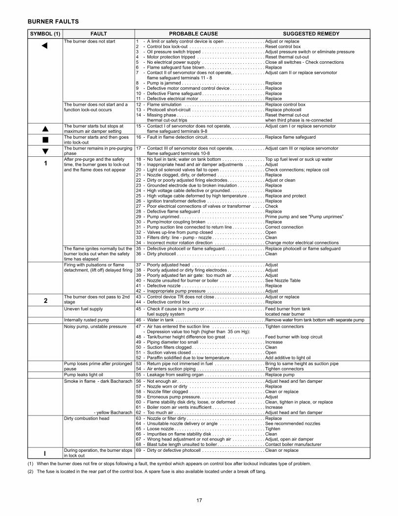
BURNER FAULTS
(1) When the burner does not fire or stops following a fault, the symbol which appears on control box after lockout indicates type of problem.
(2) The fuse is located in the rear part of the control box. A spare fuse is also available located under a break off tang.
SYMBOL (1) FAULT PROBABLE CAUSE SUGGESTED REMEDYThe burner does not start 1 - A limit or safety control device is open . . . . . . . . . . . . . . . . Adjust or replace
2 - Control box lock-out . . . . . . . . . . . . . . . . . . . . . . . . . . . . . . Reset control box3 - Oil pressure switch tripped . . . . . . . . . . . . . . . . . . . . . . . . . Adjust pressure switch or eliminate pressure4 - Motor protection tripped . . . . . . . . . . . . . . . . . . . . . . . . . . . Reset thermal cut-out5 - No electrical power supply . . . . . . . . . . . . . . . . . . . . . . . . . Close all switches - Check connections6 - Flame safeguard fuse blown . . . . . . . . . . . . . . . . . . . . . . . . Replace7 - Contact II of servomotor does not operate, . . . . . . . . . . . . . Adjust cam II or replace servomotor
flame safeguard terminals 11 - 88 - Pump is jammed . . . . . . . . . . . . . . . . . . . . . . . . . . . . . . . . . Replace9 - Defective motor command control device . . . . . . . . . . . . . . Replace10 - Defective Flame safeguard . . . . . . . . . . . . . . . . . . . . . . . . . Replace11 - Defective electrical motor . . . . . . . . . . . . . . . . . . . . . . . . . . Replace
The burner does not start and a function lock-out occurs
12 - Flame simulation . . . . . . . . . . . . . . . . . . . . . . . . . . . . . . . . Replace control box13 - Photocell short-circuit . . . . . . . . . . . . . . . . . . . . . . . . . . . . . Replace photocell14 - Missing phase . . . . . . . . . . . . . . . . . . . . . . . . . . . . . . . . . . . Reset thermal cut-out
thermal cut-out trips when third phase is re-connectedThe burner starts but stops at maximum air damper setting
15 - Contact I of servomotor does not operate, . . . . . . . . . . . . . Adjust cam I or replace servomotorflame safeguard terminals 9-8
The burner starts and then goes into lock-out
16 - Fault in flame detection circuit. . . . . . . . . . . . . . . . . . . . . . . Replace flame safeguard
The burner remains in pre-purging phase
17 - Contact III of servomotor does not operate, . . . . . . . . . . . . Adjust cam III or replace servomotorflame safeguard terminals 10-8
After pre-purge and the safety time, the burner goes to lock-out and the flame does not appear
18 - No fuel in tank; water on tank bottom . . . . . . . . . . . . . . . . . Top up fuel level or suck up water19 - Inappropriate head and air damper adjustments . . . . . . . . Adjust20 - Light oil solenoid valves fail to open . . . . . . . . . . . . . . . . . . Check connections; replace coil21 - Nozzle clogged, dirty, or deformed . . . . . . . . . . . . . . . . . . . Replace22 - Dirty or poorly adjusted firing electrodes. . . . . . . . . . . . . . . Adjust or clean23 - Grounded electrode due to broken insulation . . . . . . . . . . . Replace24 - High voltage cable defective or grounded. . . . . . . . . . . . . . Replace25 - High voltage cable deformed by high temperature . . . . . . . Replace and protect26 - Ignition transformer defective . . . . . . . . . . . . . . . . . . . . . . . Replace27 - Poor electrical connections of valves or transformer . . . . . Check28 - Defective flame safeguard . . . . . . . . . . . . . . . . . . . . . . . . . Replace29 - Pump unprimed. . . . . . . . . . . . . . . . . . . . . . . . . . . . . . . . . . Prime pump and see "Pump unprimes”30 - Pump/motor coupling broken . . . . . . . . . . . . . . . . . . . . . . . Replace31 - Pump suction line connected to return line . . . . . . . . . . . . . Correct connection32 - Valves up-line from pump closed . . . . . . . . . . . . . . . . . . . . Open33 - Filters dirty: line - pump - nozzle . . . . . . . . . . . . . . . . . . . . . Clean34 - Incorrect motor rotation direction . . . . . . . . . . . . . . . . . . . . Change motor electrical connections
The flame ignites normally but the burner locks out when the safety time has elapsed
35 - Defective photocell or flame safeguard. . . . . . . . . . . . . . . . Replace photocell or flame safeguard36 - Dirty photocell . . . . . . . . . . . . . . . . . . . . . . . . . . . . . . . . . . . Clean
Firing with pulsations or flame detachment, (lift off) delayed firing
37 - Poorly adjusted head . . . . . . . . . . . . . . . . . . . . . . . . . . . . . Adjust38 - Poorly adjusted or dirty firing electrodes . . . . . . . . . . . . . . . Adjust39 - Poorly adjusted fan air gate: too much air . . . . . . . . . . . . . Adjust40 - Nozzle unsuited for burner or boiler . . . . . . . . . . . . . . . . . . See Nozzle Table41 - Defective nozzle . . . . . . . . . . . . . . . . . . . . . . . . . . . . . . . . . Replace42 - Inappropriate pump pressure . . . . . . . . . . . . . . . . . . . . . . . Adjust
The burner does not pass to 2nd stage
43 - Control device TR does not close . . . . . . . . . . . . . . . . . . . . Adjust or replace44 - Defective control box . . . . . . . . . . . . . . . . . . . . . . . . . . . . . Replace
Uneven fuel supply 45 - Check if cause is in pump or . . . . . . . . . . . . . . . . . . . . . . . . Feed burner from tankfuel supply system located near burner
Internally rusted pump 46 - Water in tank . . . . . . . . . . . . . . . . . . . . . . . . . . . . . . . . . . . . . . . .Remove water from tank bottom with separate pumpNoisy pump, unstable pressure 47 - Air has entered the suction line . . . . . . . . . . . . . . . . . . . . . Tighten connectors
- Depression value too high (higher than 35 cm Hg):48 - Tank/burner height difference too great . . . . . . . . . . . . . . . Feed burner with loop circuit49 - Piping diameter too small . . . . . . . . . . . . . . . . . . . . . . . . . . Increase50 - Suction filters clogged . . . . . . . . . . . . . . . . . . . . . . . . . . . . . Clean51 - Suction valves closed . . . . . . . . . . . . . . . . . . . . . . . . . . . . . Open52 - Paraffin solidified due to low temperature . . . . . . . . . . . . . . Add additive to light oil
Pump loses prime after prolonged pause
53 - Return pipe not immersed in fuel . . . . . . . . . . . . . . . . . . . . Bring to same height as suction pipe54 - Air enters suction piping . . . . . . . . . . . . . . . . . . . . . . . . . . . Tighten connectors
Pump leaks light oil 55 - Leakage from sealing organ . . . . . . . . . . . . . . . . . . . . . . . . Replace pumpSmoke in flame - dark Bacharach
- yellow Bacharach
56 - Not enough air. . . . . . . . . . . . . . . . . . . . . . . . . . . . . . . . . . . Adjust head and fan damper57 - Nozzle worn or dirty . . . . . . . . . . . . . . . . . . . . . . . . . . . . . . Replace58 - Nozzle filter clogged . . . . . . . . . . . . . . . . . . . . . . . . . . . . . . Clean or replace59 - Erroneous pump pressure. . . . . . . . . . . . . . . . . . . . . . . . . . Adjust60 - Flame stability disk dirty, loose, or deformed . . . . . . . . . . . Clean, tighten in place, or replace61 - Boiler room air vents insufficient . . . . . . . . . . . . . . . . . . . . . Increase62 - Too much air . . . . . . . . . . . . . . . . . . . . . . . . . . . . . . . . . . . . Adjust head and fan damper
Dirty combustion head 63 - Nozzle or filter dirty . . . . . . . . . . . . . . . . . . . . . . . . . . . . . . . Replace64 - Unsuitable nozzle delivery or angle . . . . . . . . . . . . . . . . . . See recommended nozzles65 - Loose nozzle . . . . . . . . . . . . . . . . . . . . . . . . . . . . . . . . . . . . Tighten66 - Impurities on flame stability disk . . . . . . . . . . . . . . . . . . . . . Clean67 - Wrong head adjustment or not enough air . . . . . . . . . . . . . Adjust, open air damper68 - Blast tube length unsuited to boiler . . . . . . . . . . . . . . . . . . . Contact boiler manufacturer
During operation, the burner stops in lock out
69 - Dirty or defective photocell . . . . . . . . . . . . . . . . . . . . . . . . . Clean or replace
1
2
I

18
D2815
LAYOUT (A)Burners RL 70/M - RL 100/M - RL 130/M
Key to Layout (A)CMV - Motor contactorDA - Control boxFR - PhotocellMB - Terminal stripMV - Fan motorPA - Air pressure switchPO - High oil pressure switchRT - Thermal overloadS1 - Switch for following operations :
MAN = manualAUT = automatic
OFFS2 - Button for :
- = power reduction+ = power increase
SM - ServomotorTA - Ignition transformerTB - Burner ground (earth) connectionVM - Delivery pump valveVS - Delivery pump valve (safety valve)VR - Valve on nozzle return
Factory Wiring DiagramRL70 - 100 - 130/M with burner mounted Siemens LAL control
(A)D2873
Continuous fan operation Change the wire connection from terminal 7 to terminal 1, move the jumper from terminals 12-13 to terminals 4-12 and remove the wire from terminal 13 of control box.
19
(A)
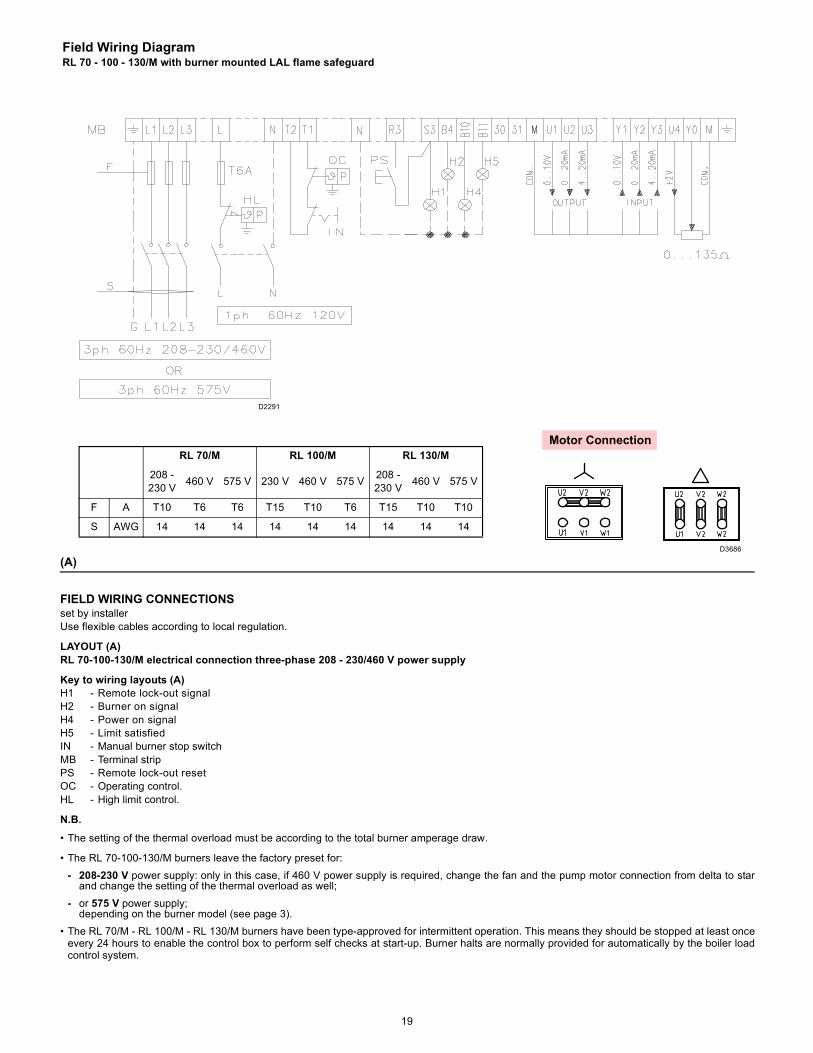
FIELD WIRING CONNECTIONSset by installerUse flexible cables according to local regulation.
LAYOUT (A)RL 70-100-130/M electrical connection three-phase 208 - 230/460 V power supply
Key to wiring layouts (A)H1 - Remote lock-out signalH2 - Burner on signalH4 - Power on signalH5 - Limit satisfiedIN - Manual burner stop switchMB - Terminal stripPS - Remote lock-out resetOC - Operating control.HL - High limit control.
N.B.• The setting of the thermal overload must be according to the total burner amperage draw.
• The RL 70-100-130/M burners leave the factory preset for:- 208-230 V power supply: only in this case, if 460 V power supply is required, change the fan and the pump motor connection from delta to star
and change the setting of the thermal overload as well;- or 575 V power supply;
depending on the burner model (see page 3).• The RL 70/M - RL 100/M - RL 130/M burners have been type-approved for intermittent operation. This means they should be stopped at least once
every 24 hours to enable the control box to perform self checks at start-up. Burner halts are normally provided for automatically by the boiler loadcontrol system.
Field Wiring DiagramRL 70 - 100 - 130/M with burner mounted LAL flame safeguard
RL 70/M RL 100/M RL 130/M
208 -230 V 460 V 575 V 230 V 460 V 575 V 208 -
230 V 460 V 575 V
F A T10 T6 T6 T15 T10 T6 T15 T10 T10
S AWG 14 14 14 14 14 14 14 14 14
D2291
Motor Connection
D3686
20
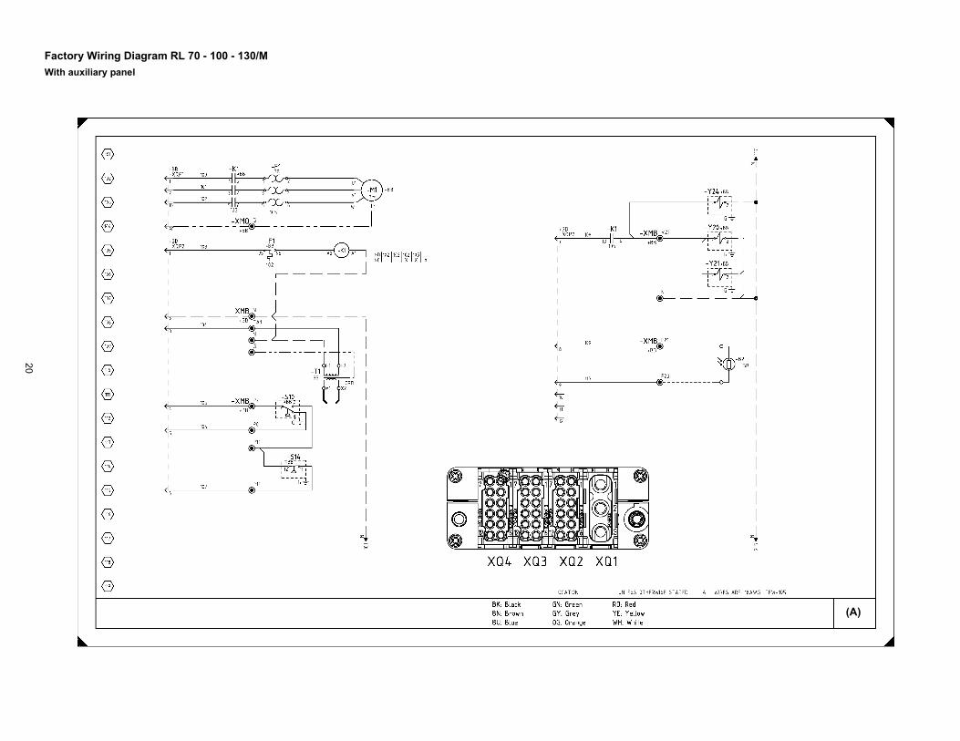
Factory Wiring Diagram RL 70 - 100 - 130/MWith auxiliary panel
(A)
21
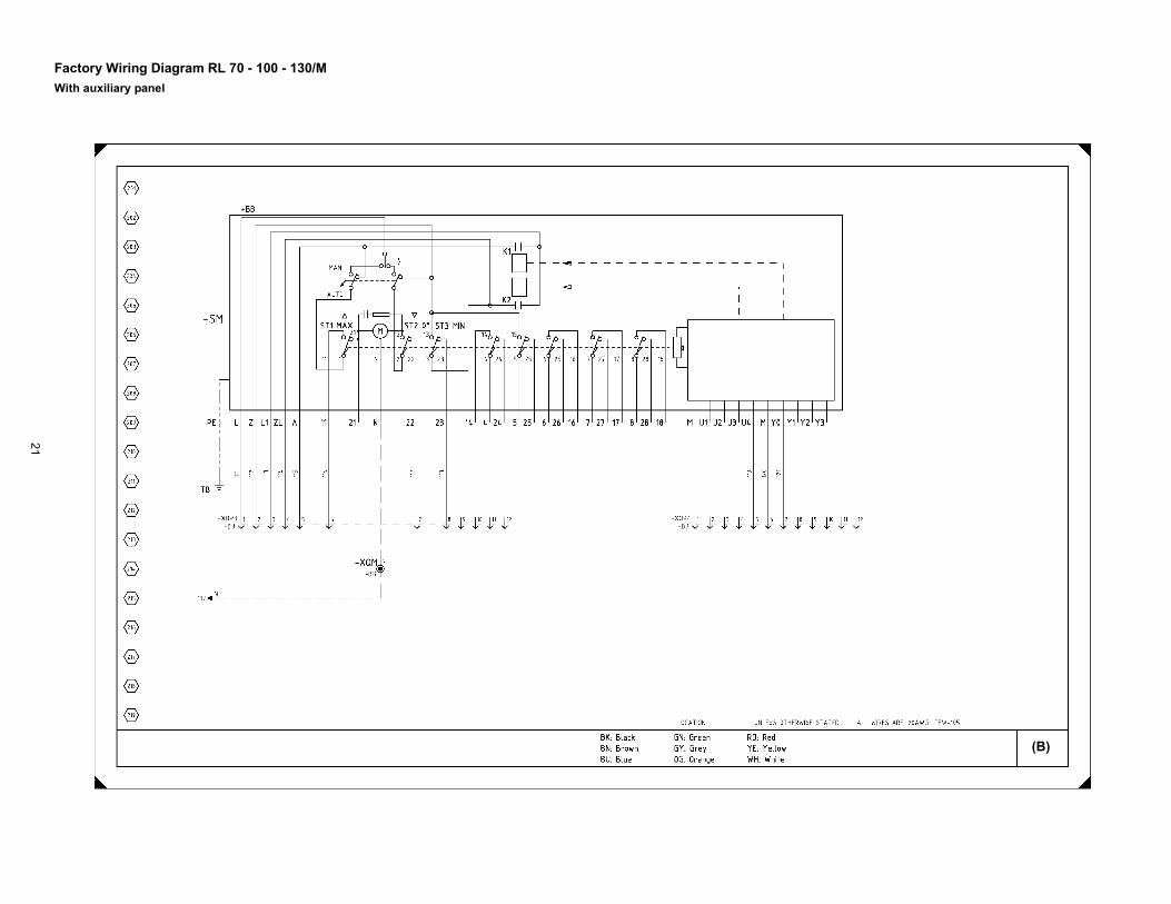
Factory Wiring Diagram RL 70 - 100 - 130/MWith auxiliary panel
(B)
22
LAYOUT (A) - (B) page 20 - 21Burners RL 70 - 100 - 130/MThe flame safeguard is in an auxiliary panel.See the internal electrical systems of the auxiliary panel in order to have the complete wiring diagram.
Key to Layouts (A) - (B)B2 - PhotocellBB - On the burnerF1 - Fan motor thermal overloadK1 - Fan motor contactorM1 - Fan motorSM - ServomotorS10 - Air pressure switchS14 - High oil pressure switchTB - Burner ground (earth) connectionT1 - Ignition transformerXMB - Burner terminal stripXMQ - Auxiliary panel terminal stripXQ1 - 3-pin plug-socketXQ2 - 12-pin plug-socketXQ3 - 12-pin plug-socketXQ4 - 12-pin plug-socketY20 - Safety oil valveY21 - Oil valve on deliveryY24 - Oil valve on return
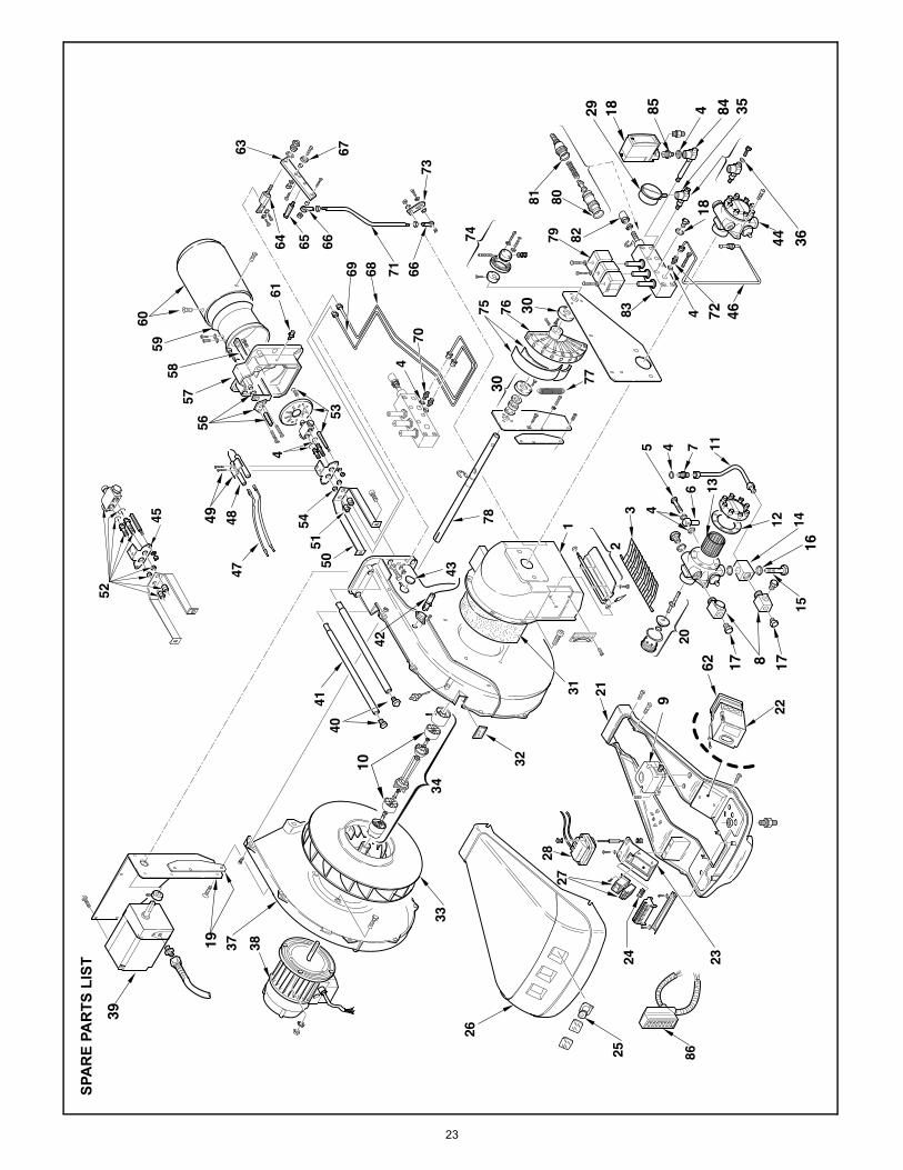
23
46
36
18
30
16
17
19
1 023456789
9
39
10
49
8 17
30
29 35
44
72
18 84485
62
SPA
RE
PAR
TS L
IST
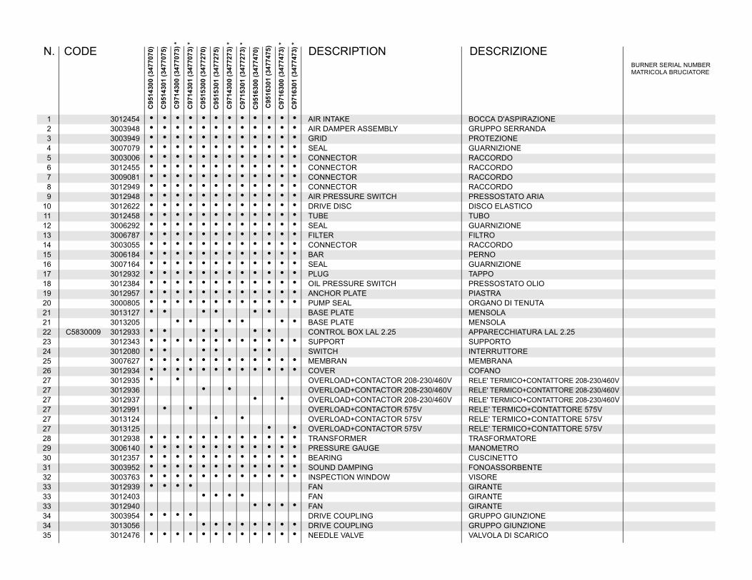
1 3012454 • • • • • • • • • • • • AIR INTAKE BOCCA D'ASPIRAZIONE2 3003948 • • • • • • • • • • • • AIR DAMPER ASSEMBLY GRUPPO SERRANDA3 3003949 • • • • • • • • • • • • GRID PROTEZIONE4 3007079 • • • • • • • • • • • • SEAL GUARNIZIONE5 3003006 • • • • • • • • • • • • CONNECTOR RACCORDO6 3012455 • • • • • • • • • • • • CONNECTOR RACCORDO7 3009081 • • • • • • • • • • • • CONNECTOR RACCORDO8 3012949 • • • • • • • • • • • • CONNECTOR RACCORDO9 3012948 • • • • • • • • • • • • AIR PRESSURE SWITCH PRESSOSTATO ARIA
10 3012622 • • • • • • • • • • • • DRIVE DISC DISCO ELASTICO11 3012458 • • • • • • • • • • • • TUBE TUBO12 3006292 • • • • • • • • • • • • SEAL GUARNIZIONE13 3006787 • • • • • • • • • • • • FILTER FILTRO14 3003055 • • • • • • • • • • • • CONNECTOR RACCORDO15 3006184 • • • • • • • • • • • • BAR PERNO16 3007164 • • • • • • • • • • • • SEAL GUARNIZIONE17 3012932 • • • • • • • • • • • • PLUG TAPPO18 3012384 • • • • • • • • • • • • OIL PRESSURE SWITCH PRESSOSTATO OLIO19 3012957 • • • • • • • • • • • • ANCHOR PLATE PIASTRA20 3000805 • • • • • • • • • • • • PUMP SEAL ORGANO DI TENUTA21 3013127 • • • • • • BASE PLATE MENSOLA21 3013205 • • • • • • BASE PLATE MENSOLA22 C5830009 3012933 • • • • • • CONTROL BOX LAL 2.25 APPARECCHIATURA LAL 2.2523 3012343 • • • • • • • • • • • • SUPPORT SUPPORTO24 3012080 • • • • • • SWITCH INTERRUTTORE25 3007627 • • • • • • • • • • • • MEMBRAN MEMBRANA26 3012934 • • • • • • • • • • • • COVER COFANO27 3012935 • • OVERLOAD+CONTACTOR 208-230/460V RELE' TERMICO+CONTATTORE 208-230/460V27 3012936 • • OVERLOAD+CONTACTOR 208-230/460V RELE' TERMICO+CONTATTORE 208-230/460V27 3012937 • • OVERLOAD+CONTACTOR 208-230/460V RELE' TERMICO+CONTATTORE 208-230/460V27 3012991 • • OVERLOAD+CONTACTOR 575V RELE' TERMICO+CONTATTORE 575V27 3013124 • • OVERLOAD+CONTACTOR 575V RELE' TERMICO+CONTATTORE 575V27 3013125 • • OVERLOAD+CONTACTOR 575V RELE' TERMICO+CONTATTORE 575V28 3012938 • • • • • • • • • • • • TRANSFORMER TRASFORMATORE29 3006140 • • • • • • • • • • • • PRESSURE GAUGE MANOMETRO30 3012357 • • • • • • • • • • • • BEARING CUSCINETTO31 3003952 • • • • • • • • • • • • SOUND DAMPING FONOASSORBENTE32 3003763 • • • • • • • • • • • • INSPECTION WINDOW VISORE33 3012939 • • • • FAN GIRANTE33 3012403 • • • • FAN GIRANTE33 3012940 • • • • FAN GIRANTE34 3003954 • • • • DRIVE COUPLING GRUPPO GIUNZIONE34 3013056 • • • • • • • • DRIVE COUPLING GRUPPO GIUNZIONE35 3012476 • • • • • • • • • • • • NEEDLE VALVE VALVOLA DI SCARICO
BURNER SERIAL NUMBERMATRICOLA BRUCIATORE
N. CODE DESCRIPTION DESCRIZIONE
C95
1430
0 (3
4770
70)
C95
1430
1 (3
4770
75)
C97
1430
0 (3
4770
73) *
C97
1430
1 (3
4770
73) *
C95
1530
0 (3
4772
70)
C95
1530
1 (3
4772
75)
C97
1430
0 (3
4772
73) *
C97
1530
1 (3
4772
73) *
C95
1630
0 (3
4774
70)
C95
1630
1 (3
4774
75)
C97
1630
0 (3
4774
73) *
C97
1630
1 (3
4774
73) *

36 3007169 • • • • • • • • • • • • O RING ANELLO OR37 3012012 • • • • • • • • • • • • HALF-SHELL GUSCIO38 3012941 • • MOTOR 208-230/460V MOTORE 208-230/460V38 3012942 • • MOTOR 208-230/460V MOTORE 208-230/460V38 3012943 • • MOTOR 208-230/460V MOTORE 208-230/460V38 3013059 • • MOTOR 575V MOTORE 575V38 3013060 • • MOTOR 575V MOTORE 575V38 3013061 • • MOTOR 575V MOTORE 575V39 3012944 • • • • • • • • • • • • SERVOMOTOR SERVOMOTORE40 3003481 • • • • • • • • • • • • SCREW VITE41 3003970 • • • • • • • • • • • • BAR PERNO42 C5360027 3006216 • • • • • • P.E. CELL FOTORESISTENZA43 3003996 • • • • • • • • • • • • PLUG TAPPO44 3006369 • • • • • • • • • • • • PUMP POMPA45 3012092 • • • • • • • • • • • • SUPPORT SUPPORTO46 3012475 • • • • • • • • • • • • TUBE TUBO47 3012959 • • • • • • • • • • • • H.T. LEAD COLLEGAMENTO48 3003796 • • • • • • • • • • • • ELECTRODE ELETTRODO49 3003495 • • • • • • • • • • • • U BOLT CAVALLOTTO50 3012461 • • • • • • • • • • • • SUPPORT SUPPORTO51 3012095 • • • • • • • • • • • • NUT DADO52 3012096 • • • • • • • • • • • • NOZZLE HOLDER ASSEMNLY GRUPPO PORTAUGELLO53 3012462 • • • • DIFFUSER DISC ELICA53 3012463 • • • • • • • • DIFFUSER DISC ELICA54 3012127 • • • • • • • • • • • • SPACER DISTANZIALE5556 3003974 • • • • • • • • • • • • CONTROL DEVICE GRUPPO REGOLATORE57 3003975 • • • • • • • • FRONT PIECE FRONTONE57 3003976 • • • • FRONT PIECE FRONTONE58 3012464 • • • • SQUARE SQUADRETTA58 3012465 • • • • SQUARE SQUADRETTA58 3012466 • • • • SQUARE SQUADRETTA59 3003983 • • • • • • • • SHUTTER OTTURATORE59 3003984 • • • • SHUTTER OTTURATORE60 3012467 • • • • END CONE IMBUTO FIAMMA60 3012468 • • • • END CONE IMBUTO FIAMMA60 3012469 • • • • END CONE IMBUTO FIAMMA61 3003322 • • • • • • • • • • • • CONNECTOR RACCORDO62 C5360001 3012950 • • • • • • • • • • • • CONTROL BOX BASE ZOCCOLO63 3012354 • • • • • • • • • • • • LEVER LEVA64 3012353 • • • • • • • • • • • • BAR PERNO65 3012352 • • • • • • • • • • • • BAR PERNO66 3006098 • • • • • • • • • • • • PIN JOINT SNODO SFERICO67 3003841 • • • • • • • • • • • • BEARING CUSCINETTO
BURNER SERIAL NUMBERMATRICOLA BRUCIATORE
N. CODE DESCRIPTION DESCRIZIONE
C95
1430
0 (3
4770
70)
C95
1430
1 (3
4770
75)
C97
1430
0 (3
4770
73) *
C97
1430
1 (3
4770
73) *
C95
1530
0 (3
4772
70)
C95
1530
1 (3
4772
75)
C97
1430
0 (3
4772
73) *
C97
1530
1 (3
4772
73) *
C95
1630
0 (3
4774
70)
C95
1630
1 (3
4774
75)
C97
1630
0 (3
4774
73) *
C97
1630
1 (3
4774
73) *
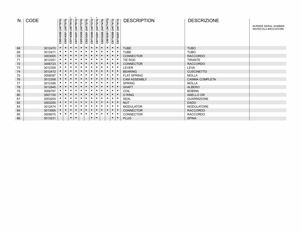
68 3012470 • • • • • • • • • • • • TUBE TUBO69 3012471 • • • • • • • • • • • • TUBE TUBO70 3003005 • • • • • • • • • • • • CONNECTOR RACCORDO71 3012351 • • • • • • • • • • • • TIE ROD TIRANTE72 3006723 • • • • • • • • • • • • CONNECTOR RACCORDO73 3012359 • • • • • • • • • • • • LEVER LEVA74 3012472 • • • • • • • • • • • • BEARING CUSCINETTO75 3006097 • • • • • • • • • • • • FLAT SPRING MOLLA76 3012358 • • • • • • • • • • • • CAM ASSEMBLY CAMMA COMPLETA77 3012356 • • • • • • • • • • • • SPRING MOLLA78 3012945 • • • • • • • • • • • • SHAFT ALBERO79 3006767 • • • • • • • • • • • • COIL BOBINA80 3007150 • • • • • • • • • • • • O RING ANELLO OR81 3003204 • • • • • • • • • • • • SEAL GUARNIZIONE82 3003200 • • • • • • • • • • • • NUT DADO83 3012474 • • • • • • • • • • • • MODULATOR MODULATORE84 3013065 • • • • • • • • • • • • CONNECTOR RACCORDO85 3009075 • • • • • • • • • • • • CONNECTOR RACCORDO86 3013231 • • • • • • PLUG SPINA
BURNER SERIAL NUMBERMATRICOLA BRUCIATORE
N. CODE DESCRIPTION DESCRIZIONE
C97
1630
0 (3
4774
73)
C97
1630
1 (3
4774
73)
C95
1430
0 (3
4770
70)
C95
1430
1 (3
4770
75)
C97
1430
0 (3
4770
73) *
C97
1430
1 (3
4770
73) *
C95
1530
0 (3
4772
70)
C95
1530
1 (3
4772
75)
C97
1430
0 (3
4772
73) *
C97
1530
1 (3
4772
73) *
C95
1630
0 (3
4774
70)
C95
1630
1 (3
4774
75)

27
BURNER START UP REPORT
Model number:
Project name:
Installing contractor:
Serial number:
Start-up date:
Phone number:
GAS OPERATION
Gas Supply Pressure:
Main Power Supply:
Control Power Supply:
Burner Firing Rate:
Manifold Pressure:
Pilot Flame Signal:
Low Fire Flame Signal:
High Fire Flame Signal:
CO2: Low Fire
O2: Low Fire
CO: Low Fire
NOX: Low Fire
Net Stack Temp - Low Fire:
Comb. Efficiency - Low Fire:
Overfire Draft:
High Fire
High Fire
High Fire
High Fire
High Fire:
High Fire:
OIL OPERATION
Oil supply pressure:
Oil suction pressure:
Control Power Supply:
Burner Firing Rate:
Low Fire Flame Signal:
High Fire Flame Signal:
Low Fire Nozzle Size:
High Fire Nozzle Size:
CO2: Low Fire
O2: Low Fire
CO: Low Fire
NOX: Low Fire
Net Stack Temp - Low Fire:
Comb. Efficiency - Low Fire:
Overfire Draft:
Smoke number:
High Fire
High Fire
High Fire
High Fire
High Fire:
High Fire:
CONTROL SETTINGS
Operating Setpoint:
High Limit Setpoint:
Low Gas Pressure:
High Gas Pressure:
Low Oil Pressure:
High Oil Pressure:
Flame Safeguard Model Number:
Modulating Signal Type:
NOTES

RIELLO S.p.A.Via degli Alpini 1I - 37045 Legnago (VR)Tel.: +39.0442.630111 Fax: +39.0442.630375http:// www.rielloburners.com
RIELLO BURNERS NORTH AMERICA35 Pond Park Road 1-800-4-RIELLO 2165 Meadowpine Blvd.Hingham, Massachusetts, 1-800-474-3556 Mississauga, Ontario, U.S.A. 02043 Canada L5N 6H6
http://www.riello-burners.com
Subject to modifications
Related Documents