20045701 (2) - 02/2012 Installation, use and maintenance instructions Light oil burners Single stage operation CODE MODEL 20045452 RDB2.2R T1 BF FCX22 20045453 RDB2.2R T3 BF FCX30

Welcome message from author
This document is posted to help you gain knowledge. Please leave a comment to let me know what you think about it! Share it to your friends and learn new things together.
Transcript
20045701 (2) - 02/2012
Installation, use and maintenance instructions
Light oil burners
Single stage operation
CODE MODEL
20045452 RDB2.2R T1 BF FCX22
20045453 RDB2.2R T3 BF FCX30


1 20045701
Contents
1 Information and general instructions . . . . . . . . . . . . . . . . . . . . . . . . . . . . . . . . . . . . . . . . . . . . . . . . . . . . . . . . . . . . . . . . . . . . . 3
1.1 Information about the instruction manual . . . . . . . . . . . . . . . . . . . . . . . . . . . . . . . . . . . . . . . . . . . . . . . . . . . . . . . . . . . . 31.1.1 Introduction . . . . . . . . . . . . . . . . . . . . . . . . . . . . . . . . . . . . . . . . . . . . . . . . . . . . . . . . . . . . . . . . . . . . . . . . . . . . . . . . . . 31.1.2 General dangers . . . . . . . . . . . . . . . . . . . . . . . . . . . . . . . . . . . . . . . . . . . . . . . . . . . . . . . . . . . . . . . . . . . . . . . . . . . . . . 31.1.3 Safety precautions . . . . . . . . . . . . . . . . . . . . . . . . . . . . . . . . . . . . . . . . . . . . . . . . . . . . . . . . . . . . . . . . . . . . . . . . . . . . . 31.1.4 Danger: live components . . . . . . . . . . . . . . . . . . . . . . . . . . . . . . . . . . . . . . . . . . . . . . . . . . . . . . . . . . . . . . . . . . . . . . . . 3
1.2 Guarantee and responsibility . . . . . . . . . . . . . . . . . . . . . . . . . . . . . . . . . . . . . . . . . . . . . . . . . . . . . . . . . . . . . . . . . . . . . 41.2.1 Owner’s responsibility . . . . . . . . . . . . . . . . . . . . . . . . . . . . . . . . . . . . . . . . . . . . . . . . . . . . . . . . . . . . . . . . . . . . . . . . . . 4
2 Safety and prevention. . . . . . . . . . . . . . . . . . . . . . . . . . . . . . . . . . . . . . . . . . . . . . . . . . . . . . . . . . . . . . . . . . . . . . . . . . . . . . . . . . 5
2.1 Introduction . . . . . . . . . . . . . . . . . . . . . . . . . . . . . . . . . . . . . . . . . . . . . . . . . . . . . . . . . . . . . . . . . . . . . . . . . . . . . . . . . . 5
2.2 Personnel training . . . . . . . . . . . . . . . . . . . . . . . . . . . . . . . . . . . . . . . . . . . . . . . . . . . . . . . . . . . . . . . . . . . . . . . . . . . . . 5
3 Technical description of the burner . . . . . . . . . . . . . . . . . . . . . . . . . . . . . . . . . . . . . . . . . . . . . . . . . . . . . . . . . . . . . . . . . . . . . . 6
3.1 Technical data . . . . . . . . . . . . . . . . . . . . . . . . . . . . . . . . . . . . . . . . . . . . . . . . . . . . . . . . . . . . . . . . . . . . . . . . . . . . . . . . 6
3.2 Burner models designation . . . . . . . . . . . . . . . . . . . . . . . . . . . . . . . . . . . . . . . . . . . . . . . . . . . . . . . . . . . . . . . . . . . . . . 6
3.3 Accessories (optional) . . . . . . . . . . . . . . . . . . . . . . . . . . . . . . . . . . . . . . . . . . . . . . . . . . . . . . . . . . . . . . . . . . . . . . . . . . 6
3.4 Burner description . . . . . . . . . . . . . . . . . . . . . . . . . . . . . . . . . . . . . . . . . . . . . . . . . . . . . . . . . . . . . . . . . . . . . . . . . . . . . 7
3.5 Packaging - weight - Approximate measurements. . . . . . . . . . . . . . . . . . . . . . . . . . . . . . . . . . . . . . . . . . . . . . . . . . . . . 7
3.6 Standard equipment. . . . . . . . . . . . . . . . . . . . . . . . . . . . . . . . . . . . . . . . . . . . . . . . . . . . . . . . . . . . . . . . . . . . . . . . . . . . 7
3.7 Burner dimensions . . . . . . . . . . . . . . . . . . . . . . . . . . . . . . . . . . . . . . . . . . . . . . . . . . . . . . . . . . . . . . . . . . . . . . . . . . . . . 8
3.8 Firing rate . . . . . . . . . . . . . . . . . . . . . . . . . . . . . . . . . . . . . . . . . . . . . . . . . . . . . . . . . . . . . . . . . . . . . . . . . . . . . . . . . . . . 9
4 Installation . . . . . . . . . . . . . . . . . . . . . . . . . . . . . . . . . . . . . . . . . . . . . . . . . . . . . . . . . . . . . . . . . . . . . . . . . . . . . . . . . . . . . . . . . . 10
4.1 Installation precautions . . . . . . . . . . . . . . . . . . . . . . . . . . . . . . . . . . . . . . . . . . . . . . . . . . . . . . . . . . . . . . . . . . . . . . . . 10
4.2 Notes on safety for the installation . . . . . . . . . . . . . . . . . . . . . . . . . . . . . . . . . . . . . . . . . . . . . . . . . . . . . . . . . . . . . . . . 11
4.3 Handling . . . . . . . . . . . . . . . . . . . . . . . . . . . . . . . . . . . . . . . . . . . . . . . . . . . . . . . . . . . . . . . . . . . . . . . . . . . . . . . . . . . . 11
4.4 Preliminary checks . . . . . . . . . . . . . . . . . . . . . . . . . . . . . . . . . . . . . . . . . . . . . . . . . . . . . . . . . . . . . . . . . . . . . . . . . . . . 11
4.5 Working position. . . . . . . . . . . . . . . . . . . . . . . . . . . . . . . . . . . . . . . . . . . . . . . . . . . . . . . . . . . . . . . . . . . . . . . . . . . . . . 11
4.6 Burner assembly . . . . . . . . . . . . . . . . . . . . . . . . . . . . . . . . . . . . . . . . . . . . . . . . . . . . . . . . . . . . . . . . . . . . . . . . . . . . . 124.6.1 CF - Chimney Vent Application . . . . . . . . . . . . . . . . . . . . . . . . . . . . . . . . . . . . . . . . . . . . . . . . . . . . . . . . . . . . . . . . . . 124.6.2 BF - Direct Vent Application . . . . . . . . . . . . . . . . . . . . . . . . . . . . . . . . . . . . . . . . . . . . . . . . . . . . . . . . . . . . . . . . . . . . . 12
4.7 A typical layout for RDB burner intake air . . . . . . . . . . . . . . . . . . . . . . . . . . . . . . . . . . . . . . . . . . . . . . . . . . . . . . . . . . 13
4.8 Boiler fixing. . . . . . . . . . . . . . . . . . . . . . . . . . . . . . . . . . . . . . . . . . . . . . . . . . . . . . . . . . . . . . . . . . . . . . . . . . . . . . . . . . 14
4.9 Hydraulic systems . . . . . . . . . . . . . . . . . . . . . . . . . . . . . . . . . . . . . . . . . . . . . . . . . . . . . . . . . . . . . . . . . . . . . . . . . . . . 154.9.1 General warnings . . . . . . . . . . . . . . . . . . . . . . . . . . . . . . . . . . . . . . . . . . . . . . . . . . . . . . . . . . . . . . . . . . . . . . . . . . . . . 154.9.2 Oil line connections . . . . . . . . . . . . . . . . . . . . . . . . . . . . . . . . . . . . . . . . . . . . . . . . . . . . . . . . . . . . . . . . . . . . . . . . . . . 154.9.3 Priming pump. . . . . . . . . . . . . . . . . . . . . . . . . . . . . . . . . . . . . . . . . . . . . . . . . . . . . . . . . . . . . . . . . . . . . . . . . . . . . . . . 16
4.10 Electrical wiring . . . . . . . . . . . . . . . . . . . . . . . . . . . . . . . . . . . . . . . . . . . . . . . . . . . . . . . . . . . . . . . . . . . . . . . . . . . . . . 174.10.1 Control box. . . . . . . . . . . . . . . . . . . . . . . . . . . . . . . . . . . . . . . . . . . . . . . . . . . . . . . . . . . . . . . . . . . . . . . . . . . . . . . . . . 17
4.11 Electrical wiring . . . . . . . . . . . . . . . . . . . . . . . . . . . . . . . . . . . . . . . . . . . . . . . . . . . . . . . . . . . . . . . . . . . . . . . . . . . . . . 18
5 Burner operation. . . . . . . . . . . . . . . . . . . . . . . . . . . . . . . . . . . . . . . . . . . . . . . . . . . . . . . . . . . . . . . . . . . . . . . . . . . . . . . . . . . . . 19
5.1 Combustion adjustment . . . . . . . . . . . . . . . . . . . . . . . . . . . . . . . . . . . . . . . . . . . . . . . . . . . . . . . . . . . . . . . . . . . . . . . . 19
5.2 Nozzles . . . . . . . . . . . . . . . . . . . . . . . . . . . . . . . . . . . . . . . . . . . . . . . . . . . . . . . . . . . . . . . . . . . . . . . . . . . . . . . . . . . . 195.2.1 Nozzles recommended . . . . . . . . . . . . . . . . . . . . . . . . . . . . . . . . . . . . . . . . . . . . . . . . . . . . . . . . . . . . . . . . . . . . . . . . 19
5.3 Pump pressure. . . . . . . . . . . . . . . . . . . . . . . . . . . . . . . . . . . . . . . . . . . . . . . . . . . . . . . . . . . . . . . . . . . . . . . . . . . . . . . 19
5.4 Burner adjustment table . . . . . . . . . . . . . . . . . . . . . . . . . . . . . . . . . . . . . . . . . . . . . . . . . . . . . . . . . . . . . . . . . . . . . . . . 20
5.5 Air damper adjustment . . . . . . . . . . . . . . . . . . . . . . . . . . . . . . . . . . . . . . . . . . . . . . . . . . . . . . . . . . . . . . . . . . . . . . . . . 21
5.6 Electrodes setting. . . . . . . . . . . . . . . . . . . . . . . . . . . . . . . . . . . . . . . . . . . . . . . . . . . . . . . . . . . . . . . . . . . . . . . . . . . . . 22
5.7 Fuel heating . . . . . . . . . . . . . . . . . . . . . . . . . . . . . . . . . . . . . . . . . . . . . . . . . . . . . . . . . . . . . . . . . . . . . . . . . . . . . . . . . 22
5.8 Burner start-up cycle . . . . . . . . . . . . . . . . . . . . . . . . . . . . . . . . . . . . . . . . . . . . . . . . . . . . . . . . . . . . . . . . . . . . . . . . . . 22
20045701 2
Contents
6 Maintenance . . . . . . . . . . . . . . . . . . . . . . . . . . . . . . . . . . . . . . . . . . . . . . . . . . . . . . . . . . . . . . . . . . . . . . . . . . . . . . . . . . . . . . . . 23
6.1 Notes on safety for the maintenance . . . . . . . . . . . . . . . . . . . . . . . . . . . . . . . . . . . . . . . . . . . . . . . . . . . . . . . . . . . . . . 23
6.2 Maintenance programme. . . . . . . . . . . . . . . . . . . . . . . . . . . . . . . . . . . . . . . . . . . . . . . . . . . . . . . . . . . . . . . . . . . . . . . 236.2.1 Maintenance frequency . . . . . . . . . . . . . . . . . . . . . . . . . . . . . . . . . . . . . . . . . . . . . . . . . . . . . . . . . . . . . . . . . . . . . . . . 236.2.2 Checking and cleaning . . . . . . . . . . . . . . . . . . . . . . . . . . . . . . . . . . . . . . . . . . . . . . . . . . . . . . . . . . . . . . . . . . . . . . . . 23
7 Faults / Solutions . . . . . . . . . . . . . . . . . . . . . . . . . . . . . . . . . . . . . . . . . . . . . . . . . . . . . . . . . . . . . . . . . . . . . . . . . . . . . . . . . . . . 24
8 Spare parts . . . . . . . . . . . . . . . . . . . . . . . . . . . . . . . . . . . . . . . . . . . . . . . . . . . . . . . . . . . . . . . . . . . . . . . . . . . . . . . . . . . . . . . . . 25
8.1 Exploded spare parts. . . . . . . . . . . . . . . . . . . . . . . . . . . . . . . . . . . . . . . . . . . . . . . . . . . . . . . . . . . . . . . . . . . . . . . . . . 25
8.2 Spare parts list. . . . . . . . . . . . . . . . . . . . . . . . . . . . . . . . . . . . . . . . . . . . . . . . . . . . . . . . . . . . . . . . . . . . . . . . . . . . . . . 26

Information and general instructions
3 20045701
1.1 Information about the instruction manual
1.1.1 Introduction
The instruction manual supplied with the burner: is an integral and essential part of the product and must not be
separated from it; it must therefore be kept carefully for anynecessary consultation and must accompany the burner evenif it is transferred to another owner or user, or to another sys-tem. If the manual is lost or damaged, another copy must berequested from the Technical Assistance Service of the area;
is designed for use by qualified personnel; offers important indications and instructions relating to the
installation safety, start-up, use and maintenance of theburner.
Symbols used in the manual
In some parts of the manual you will see triangular DANGERsigns. Pay great attention to these, as they indicate a situationof potential danger.
1.1.2 General dangers
The dangers can be of 3 levels, as indicated below.
1.1.3 Safety precautions
Good safety practices must be used when working on burnerequipment. The potential energy in the electrical supply, fuel andrelated equipment must be handled with extreme care to preventequipment failures, injuries and potential death.
1.1.4 Danger: live components
Other symbols
This symbol indicates a list.
Abbreviations usedCh. ChapterFig. FigurePag. PageSec. SectionTab. Table
Delivery of the system and the instruction manual
When the system is delivered, it is important that: The instruction manual is supplied to the user by the system
manufacturer, with the recommendation to keep it in the roomwhere the heat generator is to be installed.
The instruction manual shows:– the serial number of the burner;
– the address and telephone number of the nearest Assis-tance Centre;
The system supplier carefully informs the user about:– the use of the system, – any further tests that may be necessary before the system is
started up, – maintenance and the need to have the system checked at
least once a year by the manufacturer or another specialisedtechnician.To ensure a periodic check, the manufacturer recommendsthe drawing up of a Maintenance Contract.
1 Information and general instructions
WARNING
READ THESE INSTRUCTIONS AND SAVE FORREFERENCE
DANGER
Maximum danger level! This symbol indicates operations which, if not car-ried out correctly, cause serious injury, death orlong-term health risks.
WARNING
This symbol indicates operations which, if not car-ried out correctly, may cause serious injury, deathor long-term health risks.
CAUTION
This symbol indicates operations which, if not car-ried out correctly, may cause damage to the ma-chine and/or injury to people.
WARNING
If you smell gas, open window, extinguish any openflames, stay away from electrical switches, evacu-ate the building and immediately call the gas com-pany.
If this equipment is not installed, operated, operatedand maintained in accordance with the manufactur-ers intructions, this product could expose you tosubstances in fuel or from fuel combustion whichcan cause death or serious illness.
WARNING
Improper servicing of this equipment may create apotential hazard to equipment and operators.
Servicing must be done by a fully trained andqualified personnel.
DANGER
This symbol indicates operations which, if not car-ried out correctly, lead to electric shocks with lethalconsequences.
ENVIRONMENTAL PROTECTION
This symbol gives indications for the use of the ma-chine with respect for the environment.
............................................................................................
...........................................................................................
...........................................................................................
...........................................................................................

20045701 4
Information and general instructions
1.2 Guarantee and responsibility
The manufacturer guarantees its new products from the installa-tion date, in accordance with the regulations in force and/or thesales contract. At the moment of the first start-up, check that theburner is integral and complete.
In particular, the rights to the guarantee and the responsibilitywill no longer be valid, in the event of damage to things or injuryto people, if such damage/injury was due to any of the followingcauses: incorrect installation, start-up, use and maintenance of the
burner; improper, incorrect or unreasonable use of the burner; intervention of unqualified personnel; carrying out of non authorised modifications on the equipment; use of the burner with safety devices that are faulty, incorrectly
applied and/or not working; installation of untested supplementary components on the
burner; powering of the burner with unsuitable fuels; faults in the fuel power supply system; use of the burner even following an error and/or an irregularity; repairs and/or overhauls incorrectly carried out; modification of the combustion chamber with inserts that pre-
vent the regular development of the flame, as structurallyestablished;
insufficient and inappropriate surveillance and care of thoseburner components most subject to wear and tear;
use of non-original components, including spare parts, kits,accessories and optionals;
force majeure.
The manufacturer furthermore declines any and every re-sponsibility for the failure to observe the contents of thismanual.
1.2.1 Owner’s responsibility
Please pay attention to the Safety Warnings contained withinthis instruction manual. Keep this manual for your records andprovide it to your quali fi ed service agency for use in profession-ally setting up and maintaining your burner.
Your burner will provide years of ef fi cient operation if it is pro-fessionally installed and maintained by a qualifi ed service tech-nician. If at any time the burner does not appear to be operatingproperly, immediately contact your qualifi ed service agency forconsultation.
We recommend annual inspection/service of your gas heatingsystem by a qualifi ed service agency.
Failure to follow these instructions, misuse, or incorrect adjust-ment of the burner could lead to equipment malfunction and re-sult in asphyxiation, explosion or fire.
WARNING
Failure to observe the information given in this man-ual, operating negligence, incorrect installation andthe carrying out of non authorised modifications willresult in the annulment by the manufacturer of theguarantee that it supplies with the burner.
WARNING
If you smell gas: Do not touch any electrical items. Open all windows. Close all gas supply valves. Contact your local gas authority immediately.
• Do not store flammable or hazardous materialsin the vicinity of fuel burning appliances.
• Improper installation, adjustment, alteration,service or maintenance can cause propertydamage, personal injury or death.
• Refer to this manual for instructional or addition-al information.
• Consult a certified installer, service representa-tive or the gas supplier for further assistance.
• Burner shall be installed in accordance withmanufacturers requirements as outlined in thismanual, local codes and authorities having ju-risdiction.

Safety and prevention
5 20045701
2.1 Introduction
The burners have been designed and built in compliance withcurrent regulations and directives, applying the known technicalrules of safety and envisaging all the potential danger situations.
It is necessary, however, to bear in mind that the imprudent andclumsy use of the equipment may lead to situations of death riskfor the user or third parties, as well as the damaging of the burn-er or other items. Inattention, thoughtlessness and excessiveconfidence often cause accidents; the same applies to tirednessand sleepiness.
It is a good idea to remember the following: The burner must only be used as expressly described.
Any other use should be considered improper and thereforedangerous.In particular:it can be applied to boilers operating with water, steam,diathermic oil, and to other users expressly named by the
manufacturer;the type and pressure of the fuel, the voltage and frequency ofthe electrical power supply, the minimum and maximum deliv-eries for which the burner has been regulated, the pressurisa-tion of the combustion chamber, the dimensions of thecombustion chamber and the room temperature must all bewithin the values indicated in the instruction manual.
Modification of the burner to alter its performance and destina-tions is not allowed.
The burner must be used in exemplary technical safety condi-tions. Any disturbances that could compromise safety must bequickly eliminated.
Opening or tampering with the burner components is notallowed, apart from the parts requiring maintenance.
Only those parts envisaged by the manufacturer can bereplaced.
2.2 Personnel training
The user is the person, body or company that has acquired themachine and intends to use it for the specific purpose. He is re-sponsible for the machine and for the training of the peopleworking around it.
The user: Undertakes to entrust the machine exclusively to suitably
trained and qualified personnel. Must take all the measures necessary to prevent unauthorised
people gaining access to the machine. Undertakes to inform his personnel in a suitable way about the
application and observance of the safety instructions. Withthat aim, he undertakes to ensure that everyone knows theuse and safety instructions for his own duties.
Must inform the manufacturer if faults or malfunctioning of theaccident prevention systems are noticed, along with any pre-sumed danger situation.
Personnel must always use the personal protective equipmentenvisaged by legislation and follow the indications given in thismanual.
Personnel must follow all the danger and caution indicationsshown on the machine.
Personnel must not carry out, on their own initiative, opera-tions or interventions that are not within their province.
Personnel are obliged to inform their superiors of every prob-lem or dangerous situation that may arise.
The assembly of parts of other makes, or any modifications,can alter the characteristics of the machine and hence com-promise operating safety. The manufacturer thereforedeclines any and all responsibility for any damage that maybe caused by the use of non-original parts.
2 Safety and prevention
20045701 6
Technical description of the burner
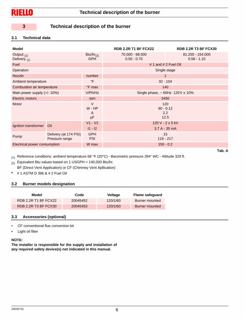
3.1 Technical data
Tab. A
(1) Reference conditions: ambient temperature 68 °F (20°C) - Barometric pressure 394” WC - Altitude 329 ft.
(2) Equivalent Btu values based on 1 USGPH = 140,000 Btu/hr.
BF (Direct Vent Application) or CF (Chimney Vent Apllication)
* # 1 ASTM D 396 & # 2 Fuel Oil
3.2 Burner models designation
3.3 Accessories (optional)
• CF conventional flue conversion kit
• Light oil filter
NOTE:The installer is responsible for the supply and installation ofany required safety device(s) not indicated in this manual.
3 Technical description of the burner
Model RDB 2.2R T1 BF FCX22 RDB 2.2R T3 BF FCX30
Output (1)Delivery (1)
Btu/hr(2)GPH
70.000 - 98.0000.50 - 0.70
81.200 - 154.0000.58 - 1.10
Fuel # 1 and # 2 Fuel Oil
Operation Single stage
Nozzle number 1
Ambient temperature °F 32 - 104
Combustion air temperature °F max 140
Main power supply (+/- 10%) V/Ph/Hz Single phase, ~ 60Hz 120V ± 10%
Electric motors rpm 3450
Motor VW - HP
AµF
12090 - 0.12
2.212.5
Ignition transformer OilV1 - V2
I1 - I2
120 V - 2 x 5 kV
3.7 A - 35 mA
PumpDelivery (at 174 PSI)Pressure range
GPHPSI
15116 - 217
Electrical power consumption W max 150 - 0.2
Model Code Voltage Flame safeguard
RDB 2.2R T1 BF FCX22 20045452 120/1/60 Burner mounted
RDB 2.2R T3 BF FCX30 20045453 120/1/60 Burner mounted

Technical description of the burner
7 20045701
3.4 Burner description
1 Oil pump2 Control box3 Reset button with lock-out lamp4 Flange with insulating gasket5 Air damper adjustment screw6 Pump pressure adjustment screw
7 Bleeder connection8 Flame detector9 Combustion head10 Air intake (CF)11 Motor
3.5 Packaging - weight - Approximate measurements
The burners are skid mounted. Outer dimensions of packaging areindicated in Tab. B.
The weight of the burner complete with packaging is indicated inTab. B.
Tab. B
3.6 Standard equipment
1 - Burner head gasket1 - Flange with insulating gasket1 - Screw of by-pass pump1 - Screw and nuts for flange1 - 4 pin plug1 - Hexagonal key1 - Nipple 3/8 - 1/44 - Screws for flange to be fixed to boiler1 - Nipple 3/8 - 3/81 - Flexible oil pipe2 - Pipe connectors2 - Female adaptors 1/4 NPT
9
4
1 7
21083
6
511
Fig. 1
D12187
inch A B C lbs
RDB 2.2R T1 BF FCX22 15 35/64“ 11 39/64“ 12 1/64“ 24.3
RDB 2.2R T3 BF FCX30 15 35/64“ 11 39/64“ 12 1/64“ 24.3Fig. 2
D36

20045701 8
Technical description of the burner
3.7 Burner dimensions
The maximum dimensions of the burner is given in Fig. 3.
Fig. 3
Flange Burner CF version
3 25/64” 8 9/64”
51/8”
51/64”
45°
ø 3
1/ 2
”
8 5
5/ 6
4”7/ 1
6”
6 11
/ 16”
D4592
253/ 6
4”
45°
9 11
/ 64”
7 3/32”
5 23/64” 5 29/32”
5 29/32”
D4087
253/ 6
4”
51/64”
8 9/64”3 25/64”
611
/ 16”
911/ 6
4”
855/ 6
4”
523/64” 529/32”
ø 3
1 /2”
ø 61/64”
Burner BF version
Technical description of the burner
9 20045701
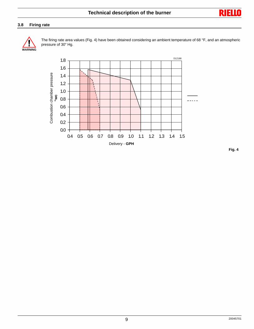
3.8 Firing rate
WARNING
The firing rate area values (Fig. 4) have been obtained considering an ambient temperature of 68 °F, and an atmosphericpressure of 30” Hg.
0.8 0.9 1.0 1.1 1.2 1.30.0
0.70.60.50.4
0.2
0.4
0.6
0.8
1.0
1.2
1.4
1.6
1.8
1.4 1.5
Fig. 4
D12188
Delivery - GPH
Com
bust
ion
cham
ber
pres
sure
“wc

20045701 10
Installation
4.1 Installation precautions
4 Installation
WARNING
AIR FOR COMBUSTION
Do not install burner in room with insufficient air for combustion. Be sure there is an adequate air supply for combustion ifthe boiler room is enclosed. It may be necessary to create a window to permit sufficient air to enter the boiler room.The installer must follow local ordinances in this regard.
CANADA It is suggested that the installer follow CSA standard B139.
USA It is suggested that the installer follow NFPA manual #31.
CHIMNEY
Be sure chimney is sufficient to handle the exhaust gases. It is recommended that only the burner be connected to thechimney. Be sure that it is clean and clear of obstructions.
OIL FILTER
An external oil filter is REQUIRED, even though there is an internal strainer in the pump.The filter should be replaced at least once a year, and the filter container should be thoroughly cleaned prior to installinga new filter cartridge.
DRAFT
Follow the instructions furnished with the heating appliance.The pressure in the combustion area should be kept as close to zero as possible. The burner will operate with a slight draftor pressure in the chamber.
ELECTRICAL CONNECTIONS
CANADA All electrical connections should be done in accordance with the C.E.C. Part 1, and all local codes.The system should be grounded.
USA All electrical connections should be done in accordance with the National Electrical Code, and all local ordi-nances. The system should be grounded.
CONTROL BURNER OPERATION
Check out the burner and explain its operation to the homeowner. Be sure to leave the Owner’s Instruction sheet with thehomeowner.
FIRE EXTINGUISHER
If required by local codes, install an approved fire extinguisher.
ELECTRICAL CONNECTIONS
In most localities, a number 14 wire should be used inside a metal conduit. The system should be grounded.A service switch should be placed close to the burner on a fireproof wall in an easily accessible location.
WARNING
The burner settings used in this manual were obtained under laboratory conditions and may vary from those ob-tained in the actual installation of the burner. Combustion results must be verified using proper combustion test equipment. Riello will not be responsible for the improper installation or set-up of the appliance.

Installation
11 20045701
4.2 Notes on safety for the installation
After carefully cleaning all around the area where the burner willbe installed, and arranging the correct lighting of the environ-ment, proceed with the installation operations.
4.3 Handling
The packaging of the burner includes a wooden platform, so it ispossible to move the burner (still packaged) with a transpallettruck or fork lift truck.
With regard to the transport in the obligatory passages, refer tothe burner dimensions shown in Fig. 3, page 8.
Check also that the area in which you are working is empty and thatthere is an adequate escape area (i.e. a free, safe area to whichyou can quickly move if the burner should fall). During the handling,keep the load at not more than 10” from the ground.
4.4 Preliminary checks
Checking the consignment
4.5 Working position
The burner is designed to work only in the positions 1, 2, 3 and 4(Fig. 5).
DANGER
All the installation, maintenance and disassemblyoperations must be carried out with the electricitysupply disconnected.
WARNING
The installation of the burner must be carried out byqualified personnel, as indicated in this manual andin accordance with the regulations of authoritieshaving jurisdiction. Reference for the recommended installation prac-tises shall be made to NFPA#31 for USA, CSAStandard B139 (oil burner only) for Canada.Oil-burning equipment shall be connected to flueshaving sufficient draft at all times, to assure safeand proper operation of the burner.
WARNING
The handling operations for the burner can be high-ly dangerous if not carried out with the greatest at-tention: keep any unauthorised people at adistance; check the integrity and suitableness of theavailable means of handling.
CAUTION
After positioning the burner near the installationpoint, correctly dispose of all residual packaging,separating the various types of material. Before proceeding with the installation operations,carefully clean all around the area where the burnerwill be installed.
CAUTION
After removing all the packaging, check the integrityof the contents. In the event of doubt, do not use theburner; contact the supplier.
The packaging elements (wooden cage or card-board box, nails, clips, plastic bags, etc.) must notbe abandoned as they are potential sources of dan-ger and pollution; they should be collected and dis-posed of in the appropriate places.
WARNING
The output of the burner must be within the boiler'sfiring rate.
WARNING
A burner label that has been tampered with, re-moved or is missing, along with anything else thatprevents the definite identification of the burnermakes any installation or maintenance work diffi-cult.
WARNING
The burner must be installed in conformity with leg-islation and local standards.
DANGER
Any other position could compromise the correctworking of the appliance. Installation 4 is not recommended for safety rea-sons.Installation 5 is forbidden for safety reasons.
Fig. 5
S8218
1 2 3
4 5

20045701 12
Installation
4.6 Burner assembly
4.6.1 CF - Chimney Vent Application
In case of CF applications, the burner shall not operate without pro-tection A)(Fig. 6) of the suction inlet.
4.6.2 BF - Direct Vent Application
In case of BF applications an optional snorkel and gasket are avail-able replacing A) with B)(Fig. 6).
This item can be supplied separately.
The combustion air supply is through a flexible or rigid pipe con-nected to the air intake.
Consequently, you must comply with the following requirementsand instructions:
The combustion air intake tube must be: fastened securely to the burner; made of a suitable material, with temperature characteristics
in the range - 22 °F to 176 °F; in compliance with all requirements of applicable regulations
in force in the country of destination. The intake-tube / burner system must not allow a loss of over
70.67 ft3/h at 0.2"wc: for instance, the above requirements willbe met if you use flues for pressure exhaust of flue gases (thecondensation kind).
Make sure the air intake tube’s inlet is positioned so that it isnot likely to be obstructed by foreign matter and, where neces-sary, use suitable screens.
The temperature of the incoming air must not exceed 104 °F; The inside diameter of the intake tube must be at least 4 inch. The intake tube can be up to 100 ft in length.
Under no circumstances should the air’s entry in the hoseintake area be obstructed.
The hose must not be blocked in any way or feature a shuttingdevice (valves, membranes etc.).
Coaxial tubes must not be installed for any reason.
WARNING
For correct bf application, the burner must be in-stalled on an appropriate BF boiler.
WARNING
Length is reduced if there are bends in the intakesection.For instance, using a tube with a smooth inside sur-face, you must allow for the following losses:– for each 45° bend, tube length is reduced by
5 ft;– for each 90° bend, tube length is reduced by
10 ft.
WARNING
Burner installation must comply with one of the in-stallations illustrated in the Fig. 7.
D5884
D5883
Fig. 6
A
B

Installation
13 20045701
4.7 A typical layout for RDB burner intake air
A Use an approved air intake kit.B Always keep intake air run to the minimum.C Maximum intake air run of 4 (inch) diameter, flexible or rigid
type of venting = 100ft. D Reduce intake air length by 10’ for every 90° elbow used. 5’
for every 45° elbow used.E It is suggested that air intake venting be insulated with R7
(min.) foil lined insu lation a minimum of 10’ from air intakesource (prevent condensation or corrosion of intake air vent-ing).
F Used approved type of intake air vacuum breaker and to beinstalled in the same room and the burner, for the event ofintake air source being blocked, this device should be testedto prove that in the event of intake air source is blocked thatthe vacuum breaker balancer is set correctly and can providesufficient air for combustion for the burner. If the room that the burner is installed into cannot provideenough air or air quality is a concern, an additional air inletsource will have to be providing to this room.
Fig. 7
S8212
RDB BF burner installation example
THIS INTAKE AIR LAYOUT FOR CHIMNEY APPLICATIONS ONLY
for retrofit applications
RDB 2.2R burner
Approved fresh air intake kit
Vacuum breaker or approved equivalent
Combustion air in
Flue gases out

20045701 14
Installation
4.8 Boiler fixing
Put on the flange 1)(Fig. 8) the screw and two nuts. Fix the flange 1)(Fig. 9) to the boiler door 4) using screws 2). If necessary, the nuts 3)(Fig. 9) interposing the insulating gas-
ket 5).
Fig. 8
1
E9095
5
1
E9094
2
4
3
Fig. 9

Installation
15 20045701
4.9 Hydraulic systems
4.9.1 General warnings
On the market we can find many variants of liquid bio fuels and alsoblends of mineral and bio-fuels of various origin, including low qual-ity or not standardised products.For this very important reason, damage to burner hydraulic compo-nents can occur, when the fuel is changed.
4.9.2 Oil line connections
This burner is shipped with the oil pump set to operate on a singleline system.
To operate on a two-line system the by-pass plug 3)(Fig. 10) mustbe installed.
Pump pressure must be set at time of burner start-up.
A pressure gauge is attached to the pressure port 4)(Fig. 10) forpressure readings. Two pipe connectors 2) are supplied with theburner for connection to either a single or twoline system. Also supplied are two adaptors 1), two female 1/4” NPT, to adaptoil lines to burner pipe connectors. All pump port threads are British Parallel Thread design. Direct connection of NPT threads to the pump will damage thepump body. Riello manometers and vacuum gauges do not require any adapt-ers, and can be safely connected to the pump ports. An NPT (metric) adapter must be used when connecting othergauge models.
1 Adaptors2 Pipe connectors3 By-pass plug4 Pressure port5 Pressure adjuster6 Suction gauge connection
7 Valve8 Auxiliary pressure test point9 Pump cover10 Supply port11 Return port
WARNING
Do not operate a single line system with the by-pass plug installed.
Operating a single line system with the by-passplug installed will result in damage to the pumpshaft seal.
WARNING
The pump requires periodic maintenance carriedout by a qualified and authorised technician in con-formity with legislation and local standards.Maintenance is essential for the reliability of thepump, avoiding the excessive consumption of fueland consequent pollution.
WARNING
If the pump cover 9) is removed for any reason, besure the O-ring, is properly seated in the pump cov-er before re-attaching the pump cover to the pumphousing.
WARNING
The suction plug 10)(Fig. 10) is made of plastic.Once removed, it must not be used again. In single-pipe installations, the plug in the return line11)(Fig. 10) must be tottally in steel. In the two pipes systems, before starting the burnermake sure that the return pipe-line is not clogged. An excessive back pressure would cause the dam-age of the pump seal.
WARNING
Fuel pipe supply system The fuel pipe supply system must be carried
out according to the indications supplied in theinstruction manual.
It is advisable to use a pipe with internal diame-ter of 3/8".
Check periodically the pipes conditions. It is necessary to install a filter on the fuel sup-
ply line.
CAUTION
To install the by-pass plug Remove the return plug 11) and install the by-
pass plug 3) using the 2.5 mm hexagonal key.
Fig. 10D10904
2
1
9
10
311
4
5
7
6
8

20045701 16
Installation
4.9.3 Priming pump
On the system in Fig. 11 it is sufficient to loosen the suction gaugeconnection 6)(Fig. 10) and wait until oil flows out.
On the systems in Fig. 12 and Fig. 13 start the burner and wait forthe priming. Should lock-out occur prior to the arrival of the fuel,await at least 20 seconds before repeating the operation.
The pump suction should not exceed a maximum of 0,4 bar (30 cmHg). Beyond this limit gas is released from the oil. Oil pipes mustbe completely tight.
In the vacuum systems (Fig. 13) the return line should terminatewithin the oil tank at the same level as the suction line.
In this case a non-return valve is not required. Should however thereturn line arrive over the fuel level, a non-return valve is required.
This solution however is less safe than previous one, due to thepossibility of leakage of the valve.
H = difference of levelL = Max. lenght of the suction lineP = Max. lenght
WARNING
Before starting the burner, make sure that the tankreturn line is not clogged.
Obstructions in the line could cause the sealingorgan located on the pump shaft to break.
SINGLE LINE SYSTEM-PIPE LENGHTSHft
L ft3/8” 12/”
1.53.05.06.5
3365
130195
65130260325
H
P
min
. 0.3
3 f
t
D5741
Fig. 11
Fig. 12
H
D1842
P
H
TWO LINE SYSTEM-PIPE LENGHTSHft
L ft3/8” 12/”
01.643.294.936.589.8711.5
1151008065502520
33033033029523010065
WARNING
Pipe dope or Teflon tapes are NOT to be usedon any direct oil connection to the fuel pump.
The height ‘P’ in pipe length charts should notexceed 13 feet (4 m).
The vacuum should not exceed 11.44 inches ofmercury.
WARNING
An external, appropriately listed and certified oil fil-ter must be placed in the fuel line between the fueltank and the burner pump.
WARNING
ALWAYS KEEP THE VALVE FROM THE TANKSHUT OFF IF THE BURNER IS SHUT DOWN FORAN EXTENDED PERIOD OF TIME.
WARNING
IT IS IMPORTANT THAT THE FUEL LINE BECOMPLETELY SEALED AND FREE FROM AIRLEAKS OR ANY INTERNAL BLOCKAGES.
WARNING
WHEN THE BYPASS PLUG IS INSTALLED, ATWO-PIPE SYSTEM MUST BE USED OR FAIL-URE OFTHE PUMP SHAFT WILL OCCUR.
D5740
Fig. 13
HP
H

Installation
17 20045701
4.10 Electrical wiring
Testing:
Check the shut-down of the burner by opening the thermostats andthe lock-out by darkening the photoresistance.
4.10.1 Control box
To remove the control box (Fig. 14) from the burner proceed as fol-lows: loosen the screw 1), open the protection 2) and remove all
components; remove the coil 3) and loosen the two screws 4); move a little the control box and remove the high voltage
leads.
DANGER
The electrical wiring must be carried out with the electrical supply disconnected. Electrical wiring must be carried out by qualified personnel and in compliance with the regulations currently in force in
the country of destination. The manufacturer declines all responsibility for modifications or connections different from those shown in the electri-
cal layouts. Do not invert the neutral with the phase in the electrical supply line.
Any inversion would cause a lockout due to firing failure. The electrical safety of the device is obtained only when it is correctly connected to an efficient earthing system,
made according to current standards. It is necessary to check this fundamental safety requirement. In the event of doubt, have the electrical system checked by qualified personnel. Do not use the gas tubes as an earthing system for electrical devices.
The electrical system must be suitable for the maximum input power of the device,as indicated on the label and in themanual, checking in particular that the section of the cables is suitable for the input power of the appliance.
Do not touch the device with wet or damp body parts and/or in bare feet. Do not pull the electric cables. Wires of AWG 18 or 16 (0.82 or 1.31 mm2) section and standard rated 221° F. (Unless requested otherwise by local
standards and legislation).
WARNING
All the installation, maintenance and disassemblyoperations must be carried out with the electricitysupply disconnected.
The installation of the control box must be carriedout by qualified personnel, as indicated in this man-ual and in compliance with the standards and regu-lations of the laws in force.
E9151
Fig. 14
12
3
4
4
20045701 18
Installation
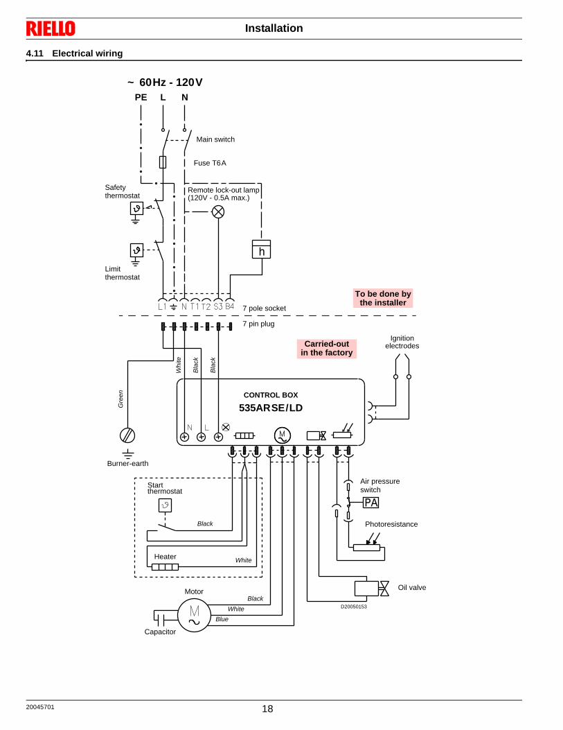
4.11 Electrical wiring
PA
h
~ 60Hz - 120VL NPE
Main switch
Fuse T6A
Safetythermostat
Limitthermostat
7 pin plug
7 pole socket
CONTROL BOX
535ARSE/LD
Ignitionelectrodes
Burner-earth
Motor
Capacitor
Heater
Start thermostat
Black
White
BlackWhite
Blue
Remote lock-out lamp(120V - 0.5A max.)
Carried-outin the factory
To be done bythe installer
Oil valve
Photoresistance
Air pressureswitch
D20050153
Whi
te
Bla
ck
Bla
ck
Gre
en
Burner operation
19 20045701
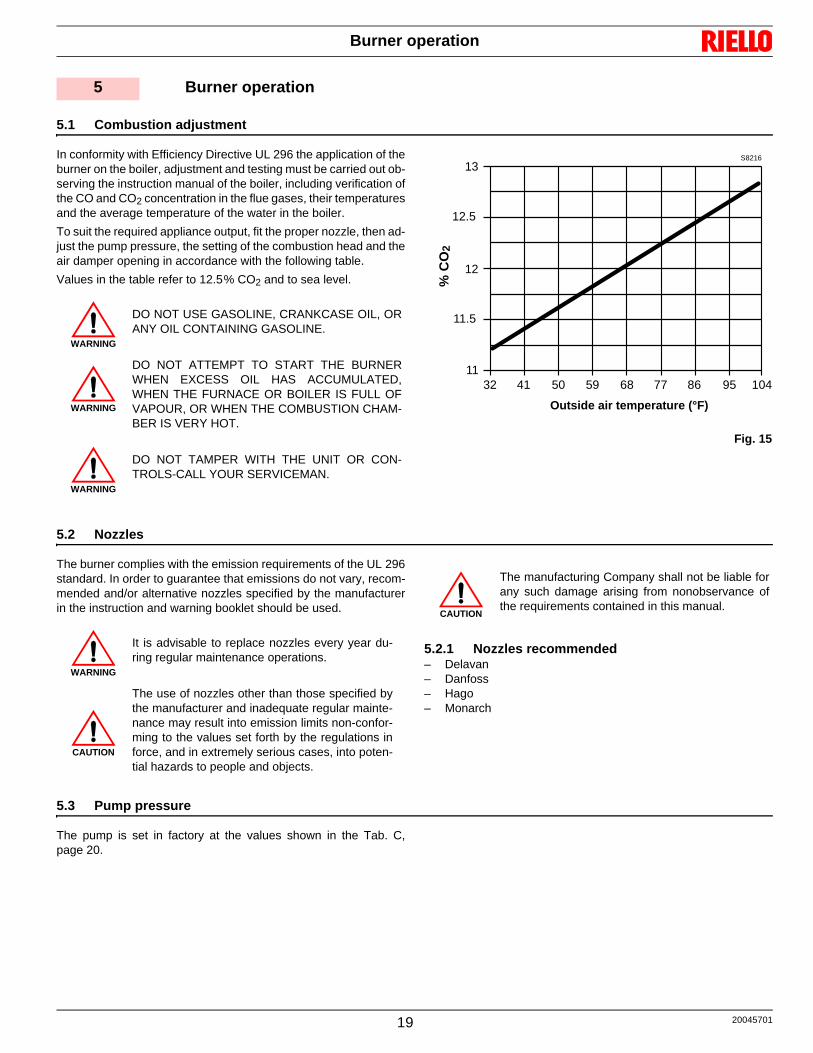
5.1 Combustion adjustment
In conformity with Efficiency Directive UL 296 the application of theburner on the boiler, adjustment and testing must be carried out ob-serving the instruction manual of the boiler, including verification ofthe CO and CO2 concentration in the flue gases, their temperaturesand the average temperature of the water in the boiler.
To suit the required appliance output, fit the proper nozzle, then ad-just the pump pressure, the setting of the combustion head and theair damper opening in accordance with the following table.
Values in the table refer to 12.5% CO2 and to sea level.
5.2 Nozzles
The burner complies with the emission requirements of the UL 296standard. In order to guarantee that emissions do not vary, recom-mended and/or alternative nozzles specified by the manufacturerin the instruction and warning booklet should be used.
5.2.1 Nozzles recommended– Delavan– Danfoss– Hago– Monarch
5.3 Pump pressure
The pump is set in factory at the values shown in the Tab. C,page 20.
5 Burner operation
WARNING
DO NOT USE GASOLINE, CRANKCASE OIL, ORANY OIL CONTAINING GASOLINE.
WARNING
DO NOT ATTEMPT TO START THE BURNERWHEN EXCESS OIL HAS ACCUMULATED,WHEN THE FURNACE OR BOILER IS FULL OFVAPOUR, OR WHEN THE COMBUSTION CHAM-BER IS VERY HOT.
WARNING
DO NOT TAMPER WITH THE UNIT OR CON-TROLS-CALL YOUR SERVICEMAN.
11
11.5
12
12.5
13
32 41 50 59 68 77 86 95 104
Fig. 15
Outside air temperature (°F)
% C
O2
S8216
WARNING
It is advisable to replace nozzles every year du-ring regular maintenance operations.
CAUTION
The use of nozzles other than those specified bythe manufacturer and inadequate regular mainte-nance may result into emission limits non-confor-ming to the values set forth by the regulations inforce, and in extremely serious cases, into poten-tial hazards to people and objects.
CAUTION
The manufacturing Company shall not be liable forany such damage arising from nonobservance ofthe requirements contained in this manual.
20045701 20
Burner operation
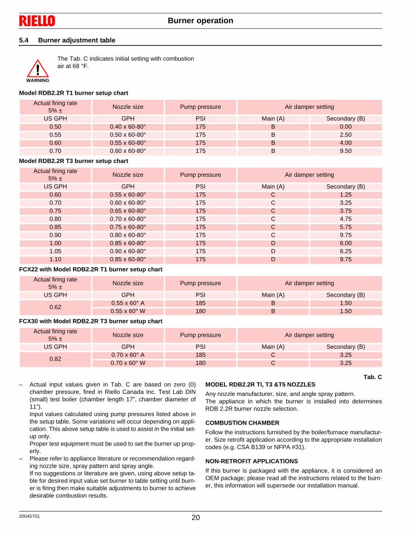
5.4 Burner adjustment table
Model RDB2.2R T1 burner setup chart
Model RDB2.2R T3 burner setup chart
FCX22 with Model RDB2.2R T1 burner setup chart
FCX30 with Model RDB2.2R T3 burner setup chart
Tab. C– Actual input values given in Tab. C are based on zero (0)
chamber pressure, fired in Riello Canada Inc. Test Lab DIN(small) test boiler (chamber length 17”, chamber diameter of11”). Input values calculated using pump pressures listed above inthe setup table. Some variations will occur depending on appli-cation. This above setup table is used to assist in the initial set-up only. Proper test equipment must be used to set the burner up prop-erly.
– Please refer to appliance literature or recommendation regard-ing nozzle size, spray pattern and spray angle.If no suggestions or literature are given, using above setup ta-ble for desired input value set burner to table setting until burn-er is firing then make suitable adjustments to burner to achievedesirable combustion results.
MODEL RDB2.2R TI, T3 &T5 NOZZLES
Any nozzle manufacturer, size, and angle spray pattern.The appliance in which the burner is installed into determinesRDB 2.2R burner nozzle selection.
COMBUSTION CHAMBER
Follow the instructions furnished by the boiler/furnace manufactur-er. Size retrofit application according to the appropriate installationcodes (e.g. CSA B139 or NFPA #31).
NON-RETROFIT APPLICATIONS
If this burner is packaged with the appliance, it is considered anOEM package; please read all the instructions related to the burn-er, this information will supersede our installation manual.
WARNING
The Tab. C indicates initial setting with combustionair at 68 °F.
Actual firing rate5% ±
Nozzle size Pump pressure Air damper setting
US GPH GPH PSI Main (A) Secondary (B)0.50 0.40 x 60-80° 175 B 0.000.55 0.50 x 60-80° 175 B 2.500.60 0.55 x 60-80° 175 B 4.000.70 0.60 x 60-80° 175 B 9.50
Actual firing rate5% ±
Nozzle size Pump pressure Air damper setting
US GPH GPH PSI Main (A) Secondary (B)0.60 0.55 x 60-80° 175 C 1.250.70 0.60 x 60-80° 175 C 3.250.75 0.65 x 60-80° 175 C 3.750.80 0.70 x 60-80° 175 C 4.750.85 0.75 x 60-80° 175 C 5.750.90 0.80 x 60-80° 175 C 9.751.00 0.85 x 60-80° 175 D 6.001.05 0.90 x 60-80° 175 D 6.251.10 0.85 x 60-80° 175 D 9.75
Actual firing rate5% ±
Nozzle size Pump pressure Air damper setting
US GPH GPH PSI Main (A) Secondary (B)
0.620.55 x 60° A 185 B 1.500.55 x 60° W 180 B 1.50
Actual firing rate5% ±
Nozzle size Pump pressure Air damper setting
US GPH GPH PSI Main (A) Secondary (B)
0.820.70 x 60° A 185 C 3.250.70 x 60° W 180 C 3.25
Burner operation
21 20045701
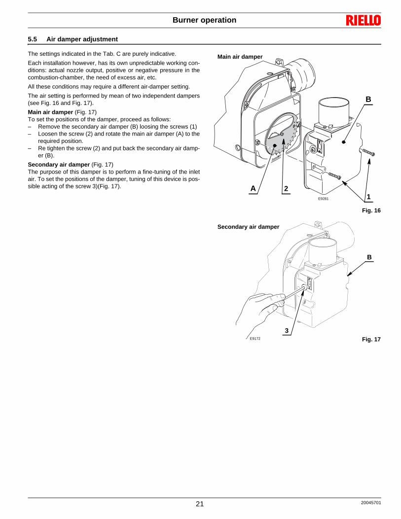
5.5 Air damper adjustment
The settings indicated in the Tab. C are purely indicative.
Each installation however, has its own unpredictable working con-ditions: actual nozzle output, positive or negative pressure in thecombustion-chamber, the need of excess air, etc.
All these conditions may require a different air-damper setting.
The air setting is performed by mean of two independent dampers(see Fig. 16 and Fig. 17).
Main air damper (Fig. 17)To set the positions of the damper, proceed as follows:– Remove the secondary air damper (B) loosing the screws (1)– Loosen the screw (2) and rotate the main air damper (A) to the
required position.– Re tighten the screw (2) and put back the secondary air damp-
er (B).
Secondary air damper (Fig. 17)The purpose of this damper is to perform a fine-tuning of the inletair. To set the positions of the damper, tuning of this device is pos-sible acting of the screw 3)(Fig. 17).
Fig. 16
Main air damper
B
12A
E9281
Fig. 17E9172
B
3
Secondary air damper

20045701 22
Burner operation
5.6 Electrodes setting
To adjust the electrodes proceed as follows: loosen the screw 1)(Fig. 18) and move the electrodes ahead; fix the screw 1).
5.7 Fuel heating
In order to obtain smooth starting and operation across its outputrange the burner is fitted with an electric resistance, which heats upthe light oil in the nozzle line.
This resistance is energized when the thermostat calls for heat andafter a delay of approximately two minutes depending on roomtemperature, the motor will start.
The resistance remains energised during working and cuts outwhen burner shuts-down.
5.8 Burner start-up cycle
Lock out is indicated by a lamp on the control box (3, Fig. 1, page 7)
WARNING
The installation and disassembly operations mustbe carried out with the electricity supply discon-nected.
WARNING
Measures must be respected!
5/32” ± 1/64”
D5230
3/32” - 7/64”
Fig. 18
1
Thermostat
Motor
Ignition transformer
Flame
Lock-out lamp
Lock-out due to failure to light BNormal
0 ÷ 150sD5329
0 ÷ 150s ~12s~12s ~5s
Resistance
Valve
B

Maintenance
23 20045701
6.1 Notes on safety for the maintenance
The periodic maintenance is essential for the good operation,safety, yield and duration of the burner.
It allows you to reduce consumption and polluting emissions andto keep the product in a reliable state over time.
Before carrying out any maintenance, cleaning or checking op-erations:
6.2 Maintenance programme
6.2.1 Maintenance frequency
The combustion system should be checked at least once a yearby a representative of the manufacturer or another specialised te-chnician.
6.2.2 Checking and cleaning
Combustion
The optimum calibration of the burner requires an analysis of theflue gases. Significant differences with respect to the previousmeasurements indicate the points where more care should be ex-ercised during maintenance.
Pump
The delivery pressure must be stable. Unusual noise must not beevident during pump operation. If the pressure is found to be unsta-ble or if the pump runs noisily, the flexible hose must be detachedfrom the line filter and the fuel must be sucked from a tank locatednear the burner. This measure permits the cause of the anomaly to be traced to ei-ther the suction piping or the pump. If the pump is found to be re-sponsible, check to make sure that the filter is not dirty. The vacuum meter is installed upstream from the filter and conse-quently will not indicate whether the filter is clogged or not. Contrarily, if the problem lies in the suction line, check to make surethat the filter is clean and that air is not entering the piping.
Flexible hoses
Check to make sure that the flexible hoses are still in good condi-tion and that they are not crushed or otherwise deformed. Checkperiodically the flexible pipes conditions.
Fuel tank
Approximately every 5 years, or whenever necessary, suck anywater or other impurities present on the bottom of the tank using aseparate pump.
Filters
Check the following filter boxes: on fuel supply line; in the pump;and clean or replace as required.If rust or other impurities are observed inside the pump, use a se-parate pump to lift any water and other impurities that may have de-posited on the bottom of the tank. Then clean the insides of thepump and the cover sealing surface.
Nozzles
Do not clean the nozzle openings; do not even open them. Replacethe nozzles every every year or whenever necessary. Combustionmust be checked after the nozzles have been changed.
Combustion head
Check to make sure that all the parts of the combustion head arein good condition, positioned correctly, free of all impurities, andthat no deformation has been caused by operation at high temper-atures.
Photoresistance
Clean the photoresistance.
Fan
Check to make sure that no dust has accumulated inside the fan oron its blades, as this condition will cause a reduction in the air flowrate and provoke polluting combustion.
Boiler
Clean the boiler as indicated in its accompanying instructions in or-der to maintain all the original combustion characteristics intact, es-pecially the flue gas temperature and combustion chamberpressure.
Leave the burner working without interruptions for 10 min. and setrightly all the components stated in this manual. Then carry out a combustion check verifying:• smoke temperature at the chimney;• content of CO2 (%);• content of CO (ppm);• smoke value according to opacity smokes index according to
Bacharach scale.
6 Maintenance
DANGER
The maintenance interventions and the calibrationof the burner must only be carried out by qualified,authorised personnel, in accordance with the con-tents of this manual and in compliance with thestandards and regulations of current laws.
DANGER
Disconnect the electricity supply from the burner bymeans of the main switch of the system.
DANGER
Close the fuel interception tap.

20045701 24
Faults / Solutions
Here below you can find some causes and the possible solutionsfor some problems that could cause a failure to start or a bad work-ing of the burner.
A fault usually makes the lock-out lamp light which is situatedinside the reset button of the control box 3)(Fig. 1, page 7).
When lock out lamp lights the burner will attempt to light only afterpushing the reset button. After this if the burner functions correctly,the lock-out can be attributed to a temporary fault.
If however the lock out continues the cause must be determinedand the solution found.
7 Faults / Solutions
FAULTS POSSIBLE CAUSES SOLUTION
The burner will not startwhen the limit thermostatcloses.
Lack of electrical supply. Check presence of voltage in the L - N clamps ofthe control box.
Check the conditions of the fuses.
Check that safety thermostat limit is not lock out.
The photoresistance sees false light. Eliminate the light.
Resistance or heating resistance. Replace them.
The connections in the control box are wronglyinserted.
Check and connect completely all the plugs.
Burner runs normally inthe prepurge and ignitioncycle and locks out after 5seconds ca.
The photoresistance is dirty. Clean it.
The photoresistance is defective. Change it.
Flame moves away or fails. Check pressure and output of the fuel.
Check air output.
Change nozzle.
Check the coil of solenoid valve.
Burner starts with an igni-tion delay.
The ignition electrodes are wrongly positioned. Adjust them according to the instructions of thismanual.
Air output is too high. Set the air output.
Nozzle dirty or worn. Replace it.

Spare parts
25 20045701
8.1 Exploded spare parts
8 Spare parts
10
30
9 11
12
14
13
32
33
31
16
17
34 15
35
18
19
25
23
26
27
28
2924
21
4
22
8
7
6
5
3
2
1
20
30
30
36
37
30

20045701 26
Spare parts
8.2 Spare parts list
*ADVISED PARTSA = Spare parts for minimum fittingsA+B = Spare parts for basic safety fittingsA+B+C = Spare parts for extended safety fittings
N. CODE
2004
5452
2004
5453
DESCRIPTION
1 3005787 • • GASKET A
2 3006384 • • FLANGE
3 3002507 • CUP - SHAPED HEAD A
3 3002447 • CUP - SHAPED HEAD A
4 20029332 • • HIGH VOLTAGE LEAD A
5 3006552 • • ELECTRODE BRACKET
6 3008855 • • NOZZLE HOLDER
7 3008845 • • COLLAR C
8 20029346 • • HEALTER ASSEMBLY B
9 3005788 • • FAN C
10 3008647 • • AIR DAMPER ASSEMBLY C
11 20045943 • • P.E. CELL A
12 3006938 • • 7 POLE SOCKET C
13 3020064 • • CAPACITOR 4.5 µF B
14 20046151 • • 7 PIN PLUG
15 3008842 • • TUBE AND CONNECTOR
16 3020475 • • PUMP C
17 3000443 • • JOINT A
18 20029357 • • MOTOR + CAPACITOR C
19 3008648 • • COIL B
20 3008856 • • CONNECTOR
21 3008649 • • PROTECTION
22 3020168 • • ELECTRODE ASSEMBLY A
23 20029354 • • COVER
24 20029334 • • CONTROL BOX B
25 20029342 • • LEAD COIL B
26 3007162 • • O-RING B
27 3008653 • • FILTER-O-RING B
28 3007582 • • NEEDLE VALVE
29 3008651 • • REGULATOR A
30 3008878 • • KIT SEALS C
31 3006992 • • OIL PIPE A
32 3005847 • • CONNECTOR 3/8” - 1/4” C
33 3006571 • • CONNECTOR 3/8” - 3/8” C
34 20029329 • • BLEEDER C
35 3006993 • • OIL PIPE
36 20045945 • • PRESSURE SWITCH A
37 20026386 • • AIR DAMPER
*


Subject to modifications
RIELLO BURNERS NORTH AMERICA
35 Pond Park Road 1-800-4-RIELLO 2165 Meadowpine Blvd
Hingham, Massachusetts, 1-800-474-3556 Mississauga, Ontario
U.S.A. 02043 Canada L5N 6H6
http://www.riello-burners.com
RIELLO S.p.A.
I-37045 Legnago (VR)
Tel.: +39.0442.630111
http:// www.riello.it
http:// www.rielloburners.com
Related Documents