Light by Gs Monk
Nov 28, 2014
Welcome message from author
This document is posted to help you gain knowledge. Please leave a comment to let me know what you think about it! Share it to your friends and learn new things together.
Transcript


160129 > mS


LIGHTPRINCIPLES AND EXPERIMENTS
BY
GEORGE S. MONKAssistant Professor of I
Jhy#'ic*
University of Chicago
FIRST EDITION
McGRAW-HILL BOOK COMPANY, INC.
YORK AND LONDON1937
COPYRIGHT, 1937, BY THE
McGiiAW-HiLL BOOK COMPANY, IN<\
PRINTED IN THE UNITED STATES OF AMKRICA
All rights reserved. This book, or
parts thereof, may not be reproducedin any form ivithout permission of
the publishers.
THE MAPLE PRESS COMPANY, YORK, PA.

PREFACE
l^ETring thirteen years' teaching of the subject of light at an
intermediate level, in classroom and laboratory, the author
has had the usual experience of finding it necessary to refer
students to several different textbooks for outside reading to
supplement the lectures. Rarely has it been possible to find a
single textbook in which the treatment of a given topic contained
the degree of elaboration consistent with the purposes of an
intermediate course. For this reason the author believed that
a text covering the essentials of geometrical and physical optics,
with the addition of several chapters covering the more recently
developed subjects of modern optics, would serve a useful
purpose.
The book is intended for students who have finished the equiva-
lent of an ordinary sophomore college course in general physics.
It is .intended for both those for whom an intermediate course
in the subject is the last, and those who expect to continue
graduate study in the field of light or in associated fields in
the physical or biological sciences. For this reason, while the
emphasises on physical optics, particularly interference, diffrac-
tion, and polarization, considerable space has also been devoted
to geometrical optics, a subject which is only too often not a
familiar one to students who will later use optical instruments
whose principles they should understand. A working knowledgeof elementary mathematics, including the fundamentals of the
differential and integral calculus, is required,- but so far as
possible each topic has been treated so that abstract mathematical
development is subordinated to the discussion of the physical
concepts involved. This has required that in several instances
where the mathematical theory is beyond the scope of the book
only the results are set down, while in other cases mere algebraic
development has been relegated to appendices. An experiment,
not necessarily novel, has been tried in basing several of the
problems upon illustrations in the book, thus supplying a.degree
of substitution for laboratory experience.

vi PREFACE
Other texts have been drawn upon freely in compiling this
one, principally Drude, "Theory of Optics"; Wood, "Physical
Optics"; Preston, "Theory of Light"; L. W. Taylor, "College
Manual of Optics"; Mann, "Manual of Optics "; Born, "Optik";
Williams, "Applications of Interferometry"; Hardy and Perrin,"Principles of Optics"; and to a lesser extent many others. The
author acknowledges with gratitude advice and criticism byhis colleagues, especially Professors H. G. Gale, A. H. Compton,and Carl Eckart, each of whom read parts of the manuscript.
Thanks are also due Dr. Rudolf Kingslake for valuable criticisms
of an earlier draft of the chapters on geometrical optics, and
Dr. J. S. Campbell for criticisms of an earlier draft of the chapters
on interference, diffraction, and polarization. Helpful criticism
by Dr. George E. Ziegler, Mr. Richard W. Hamming, and Mr.
Alfred Kelcy is acknowledged, as well as comments and correc-
tions by members of classes during the preparation of the
manuscript. A great deal is due to the helpful and stimulating
advice given by Professor F. K. Richtmyer, who suggested
important changes and additions. Acknowledgments for illustra-
tions copied or otherwise obtained froni others are for the most
part made at the point of insertion. Exceptions are: Fig. 7-8,
which was copied from a cut kindly supplied by the Bausch and
Lomb Optical Company; Fig. 11-17, which is a copy of a photo-
graph made for the author some years ago by Dr. J. S. Campbell;
Fig. 13-9, from a wash drawing made by Miss Libuse Lukas;
Fig. 14-10a, from a spectrogram made by Mr. Leonard N.
Liebermann; Fig. 16-1, supplied by the Mount Wilson Observa-
tory; and Fig. 16-12, adapted from an illustration by F. E. Foster
in the Physical Review, 23, 669, 1924.
Finally, no words of the author can express the thanks due
his wife, Ardis T. Monk, for criticisms of the manuscript, for
reading and correcting the proof, and for the preparation of the
index.ft
GEORGE S. MONK.UNIVERSITY OF CHICAGO,
September, 1937.

CONTENTSPAOK
PREFACE v
CHAPTER I
FUNDAMENTAL CONCEPTS IN GEOMETRICAL OPTICS 1
Fundamental Postulates The Ray The Optical Length of a RayFermat's Principle The Principle of Reversibility The Law
of Malus-VThe Focal Length of a Thin Lens-^l^o J"hin LensesThe Concept of Principal Planes Equivalent Focal Lengths.
CHAPTER II
THE LAWS OF IMAGE FORMATION 8
Ideal Optical Systems Refraction at a Spherical Surface
The Collinear Relation Lateral Magnification Collinear Equa-tions for a Single Refracting Surface Principal Points and Planes
Conjugate Rays and Conjugate Points LaGrangef
s LawLongitudinal Magnification Angular Magnification, Nodal Points
Mirror Systems.
CHAPTER IIIV,
COMBINATIONS OF OPTICAL SYSTEMS 19
Equation for a Thin Lens Combination of Two Systems AGeneral Lens Formula Classification of Optical Systems
Telescopic Systems.
CHAPTER IV
APERTURES IN OPTICAL SYSTEMS 31
The Stop The Aperture Stop Entrance and Exit Pupils TheChief Ray Telecentric Systems.
CHAPTER V
PHOTOMETRY THE MEASUREMENT OF LIGHT 36
Photonwftric Standards Brightness of Extended Sources Lam-bert's Cosine Law Photometric Principles Applied to Optical
Systems Numerical Aperture Natural Brightness Normal
Magnification Effects of Background.
CHAPTER VI
ABERRATIONS IN OPTICAL SYSTEMS 45
Spherical Aberration Third-order Corrections to Spherical
Aberration Coddington's Shape and Position Factors Astig-
vii

viii CONTENTSPAGK
matlsm Primary and Secondary Foci Astigmatic Difference
Coma Elimination of Coma Aplanatic Points Curvature of
Field Distortion Chromatic Aberration Cauchy's DispersionFormula The Fraunhofer Lines Two Kinds of Chromatism
Achromatizing of a Thin Lens Achromatism of the HuygensOcular The Secondary Spectrum.
CHAPTER VII
OPTICAL INSTRUMENTS. 72
The Simple Microscope The Magnifier Compound MagnifiersThe Gauss Eyepiece The Micrometer Eyepiece The Com-
pound Microscope Numerical Aperture Condensers Vertical
and Dark Field Illuminators Telescopes The Reflecting Tele-
scope Oculars (Eyepieces) The Huygens Eyepiece The Rams-den Eyepiece Erecting the Image The Spectrometer.
CHAPTER VIII
THE PRISM AND PRISM INSTRUMENTS , 88
The Prism Spectrometer Dispersion of a Prism-^Resolving Powerof a Prism The Constant-deviation Prism Index of Refraction
by Means of Total Reflection The Abbe Refractometer.
CHAPTER IX
THE NATURE OF LIGHT 100
Light as a Wave Motion Velocity, Frequency, and Wave-length
Simple Harmonic Motion Phase and Phase Angle Composi-tion of Simple Harmonic Motions Characteristics of a WaveMotion The Principle of Superposition The Wave Front The
Huygens Principle; Secondary Waves Amplitude and Intensity
The Velocity of Light Wave Velocity and Group Velpcity.
CHAPTER XINTERFERENCE OF LIGHT 120
Interference and Diffraction Compared Conditions for Inter-
ference No Destruction of Energy Methods for ProducingInterference Younfe's Experiment The Fresnel Mirrors TheFresnel Biprism The Rayleigh Refractometer The Williams
Refractometer.
CHAPTER XI
INTERFERENCE OF LIGHT DIVISION OF AMPLITUDE 1 37
^ Colors in Thip Fi|ma N^wtflTi'ff B^gffl Double and MultipleBeams Tbp> Minfrelftmi T^.piforometer The Form of the FringesThe Visibility of the Fringes, Visibility Curves Multiple
Beams The Fabry-Perot Interferometer Intensity Distribution
in Fabry-Perot Fringes Resolving Power of the Fabry-PerotInterferometer The Shape of the Fabry-Perot Fringes.

CONTENTS ix
PAGECHAPTER XII
DIFFRACTION. . . ^ 1G4
Fresnel and^raunhofer Diffraction Fresnel Zonies The Zone
Plate Cylindrical Wave Front DiffractioTT by a Circulai
Obstacle Diffraction at a Straight Edge The Cornu Spiral
Fresnel and Fraiifrfrofer Diffraction Compared Fraunhofei
Diffraction by a Single Slit By Two , Equal Slits Limit oi
Resolution The Stellar Interferometer Many Slits. TheLPiffraction Gratinp The Dispersion of a Grating Resolving Powei
of a Grating The Echelon Diffraction by a Rectangular Open-
ing Diffraction by a Circular Opening.i^ "' '' " ' ' "^^**
CHAPTER XIII
/POLARIZATION OF LIGHT 208
Polarization by Double Refraction The Wave-velocity Surface
Positive and Negative Crystals. Uriiaxial Crystals Polariza-
tion by Reflection Brewster's Law Direction of Vibration in
Crystals Plane of Polarization The Cosine-square Law of
Mains The Nicol Prism Double Image Prisms. The Wollaston
Prism Elliptically Polarized Light Wave Plates The Babinet
Compensator The Reflection of Polarized Light Rotation of
the Plane of Vibration on Reflection The Nature of Uripolarized
Light The Fresnel Rhomb General Treatment of Double
Refraction Optic Axes in Crystals Axes of Single Ray Velocity
Rotatory Polarization FresnePs Theory of Rotatory Polariza-
tion The Cornu Double Prism Half-shade Plates and Prisms.^
CHAPTER XIV
SPECTRA 250
Kinds of Spectra Early Work on Spectra The Balmer Formula
for Hydrogen The Rydberg Number Series in Spectra The
Hydrogen Series The Quantum Theory of Spectra Kirchhoff's
Law of Emission and Absorption Kirchhoff's Radiation LawStefan-Boltzman Law Wien's Displacement Laws Distribution
Laws Planck's Quantum Hypothesis The Rutherford AtomModel The Bohr Theory of Spectra Energy-level DiagramsBand Spectra of Molecules Continuous Absorption and
Emission by Atoms The Structure of Spectral Lines The
Broadening of Lines The Complex Structure of Lines.
CHAPTER XVLIGHT AND MATERIAL MEDIA 272
Absorption Laws of Absorption Surface Color of Substances
Color Transmission Absorbing Blacks Early Theories* of Dis-
persion The Electromagnetic Theory of Dispersion The Quan-tum Theory of Dispersion Residual Rays Metallic Reflection
The Optical Constants of Metals The Scattering of Light by

x CONTENTSPAGE
Gases Polarization of Scattered Light Fluorescence Polariza-
tion of Fluorescence Phosphorescence Fluorescence in GasesResonance Radiation Raman Effect The Photoelectric Effect.
CHAPTER XVITHE EFFECTS OF MAGNETIC AND ELECTRIC FIELDS 300
The Zeeman Effect Classical Theory of the Zeeman Effect
The Anomalous Zeeman Effect Quantum Theory of the Anoma-lous Zeeman Effect The Stark Effect The Faraday Effect TheKerr Magneto-optical Effect The Kerr Electro-optical Effect
The Cotton-Mouton Effect Measurement of Time Intervals
with Kerr Cells Velocity of Light with Kerr Cells.
CHAPTER XVII
THE EYE AND COLOR VISION 323
The Optical System of the Eye Defects in the Optics of the
Eye Binocular Vision The Stereoscope Optical Illusions
The Contrast Sensitivity of the Eye Flicker Sensitivity, Per-
sistence of Vision Spectral Sensitivity Color Hue Saturation
Brilliance Color and the Retina Complementary Colors
Theories of Color Vision Color Mixing versus Pigment MixingColorimeters Color Matching Graphical Representations of
Chromaticity.
EXPERIMENTS IN LIGHT1. FOCAL LENGTHS OF SIMPLE LENSES 343
2. CARDINAL POINTS OF LENS SYSTEMS 347
3. A STUDY OF ABERRATIONS 349
4. MEASUREMENT OF INDEX OF REFRACTION BY MEANS OF A
MICROSCOPE 352
5. THE PRISM SPECTROMETER 353
6. THE SPECTROPHOTOMETER 358
7. INDEX OF REFRACTION BY TOTAL REFLECTION 365
8. WAVE-LENGTH DETERMINATION BY MEANS OF FRESNEL'S BIPRISM. 368
9. MEASUREMENT OF DISTANCE WITH THE MICHELSON INTERFEROM-
ETER 370
10. MEASUREMENT OF INDEX OF REFRACTION WITH A MICHELSONINTERFEROMETER 376
11. RATIO OF Two WAVE-LENGTHS WITH A MICHELSON INTERFEROM-"""
ETER 380
12. THE FABRY-PEROT INTERFEROMETER 382
13X MEASUREMENT OF WAVE-LENGTH BY DIFFRACTION AT A SINGLE
SLIT 384
14T THE DOUBLE-SLIT INTERFEROMETER 387
15. THE DIFFRACTION GRATING 390
16. SIMPLE POLARIZATION EXPERIMENTS 395
17. ANALYSIS OF ELLIPTICALLY POLARIZED LIGHT WITH A QUARTER-WAVE PLATE 399

CONTENTS xi
PAOK
THE BABINET CQMPENSATOK 401
ROTATORY POLARIZATION OF COMMON SUBSTANCES 403
20. VERIFICATION OF BREWSTER'S LAW 407
21. THE OPTICAL CONSTANTS OF METALS 410
22. POLARIZATION OF SCATTERED LIGHT 412
23. THE FARADAY EFFECT 414
APPENDICESI. A COLLINEAR RELATION USEFUL IN GEOMETRICAL OPTICS . . . 419
II. THIRD-ORDER CORRECTION FOR SPHERICAL ABERRATION FOR A
THIN LENS IN AIR 421
III. DERIVATION OF EQUATIONS FOR ASTIGMATIC FOCAL DISTANCESAT A SINGLE REFRACTING SURFACE 424
IV. ADJUSTMENT OF A SPECTROMETER 426.
V. PREPARATION OF MIRROR SURFACES 430
VI. MAKING CROSS HAIRS 435
VII. STANDARD SOURCES FOR COLORIMETRY 436
VIII. THE FRESNEL INTEGRALS 438
TABLES OF DATAI. USEFUL WAVE-LENGTHS 443
II. INDICES OF REFRACTION OF SOME COMMON SUBSTANCES .... 444
III. REFLECTING POWERS OF SOME METALS 445
IV. FOUR-PLACE LOGARITHMS . 446
V. TRIGONOMETRIC FUNCTIONS 448
VI. LOGARITHMS OF TRIGONOMETRIC FUNCTIONS 452
INDEX 461


LIGHT: PRINCIPLES ANDEXPERIMENTS
CHAPTER I
FUNDAMENTAL CONCEPTS IN GEOMETRICAL OPTICS
1. Fundamental Postulates. Optical phenomena may bedivided into two classes. The most important of these in the
light of modern experimental discovery is that which is includedin the subject of physical optics, which deals with theories of the
nature of light and of its interaction with material objects,
together with experimental verification of these theories. Funda-mental to the study of physical optics, however, is a knowledgeof the principles of another class of optical phenomena which,after the introduction of a few fundamental experimental facts,
may be described without taking into account any hypotheses
concerning the nature of light or its interaction with material
bodies. This division of optics, concerned with image formation
by optical systems and with the laws of photometry, is called
geometrical optics, since its description is founded almost entirely
on geometrical relations. Because an understanding of the laws
of image formation is fundamental, geometrical optics will be
dealt with first.
There are certain experimental facts, sometimes regarded as
postulates, upon which the study of geometrical optics may be
based:
1. Light is propagated in straight lines in a homogeneous medium.2. Two independent beams of light may intersect each other and
thereafter be propagated as independent beams.
3. The angle of incidence of light upon a reflecting surface is equal to
the angle of reflection.
4. On refraction, the ratio of the sine of the angle of incidence to the
sine of the angle of refraction is a constant depending only on the nature
of the media (Snell's law).
1

2 LIGHT: PRINCIPLES AND EXPERIMENTS [CHAP. I
To these four facts may be added the concept of the ray and
certain deduced laws which are subject to experimentalverification.
2. The Ray. The ray may be defined as the path along which
light travels. Since for most purposes it is possible to consider
the light to be a wave motion spreading out with the same velocity
in all directions from the source (in a homogeneous and isotropic1
medium), we may say that the ray is the direction in which this
wave motion is propagated. Indeed, it is not necessary to
specify the wave form of the light, but simply to consider it to
be propagated in straight lines, since any consideration of the
physical nature of the light takes us outside the realm of geo-
metrical optics. While some exception may be taken to the use
of the ray concept as not conforming to modern ideas of the
nature of light, it is found most convenient in discussing the
characteristics of optical systems to trace the paths of the rays
from a source through succeeding media in accordance with the
preceding four laws.
3. The Optical Length of a Ray. It has been proved experi-
mentally that light undergoes a change in velocity in passing
from one medium to another, and that the index of refraction
given by Snell's law, n = sin ^'/sin r, is also given by
_ velocity in vacuo~velocity in the medium
As given here, n & is the absolute index of the medium. Since
the velocity of light in air is very little different from that in
vacuo, for optical purposes the index of air is taken as unity.
For example, the index of refraction of glass is commonly given by
__ velocity in air~~
velocity in glass'
this is the ratio of the absolute index of glass to that of air.
The optical length of a ray of length I'm a medium of index n
is denned as the product nl. Light rays from a point source at
1 A medium is said to be optically isotropic when it has the same optical
properties in all directions. Thus, water, and glass free from strains, are
isotropic. Glass with strains, and all crystals except cubic, are anisotropic.
On the other hand, any one of these is homogeneous if different portions of its
mass have the same characteristics.

SBC. 1-4] FUNDAMENTAL CONCEPTS
on the optical axis of a lens (Fig. 1-1) reach the lens at its ver-
tex B sooner than at any other point, A. At the surfaces the
rays will undergo refraction and, if the lens is free from aberra-
tions, will converge to an image point /. If the distance BB'is greater than AA' the retardation along the axis in the glass
will be more than between A and A'. While the linear pathOAA'I is greater than OBB'I, the optical paths are the same; i.e.,
the times taken by the light to go from to / over the two pathsare the same.
Let the indices of refraction of air and glass be na and na ,
respectively. Then the optical paths
OA - nn + AA' - na +A'I - na and OB na + BB' - na + B'l - na
are the same. A more general statement is that 2^ / is
constant for all rays traversing a perfect optical system, where k
FIG. 1-1.
is the linear distance in each medium of index of refraction n.
In ordinary lens systems the statement would be true only for
two adjacent rays.
4. Fermat's Principle. If, in Fig. 1-1, the angle made bythe ray OA with the axis is 6, then
I)
BO'
This is the mathematical statement of a principle first stated by
Fermat, the principle of least time, which says that the path taken
by light in passing between two points is that which it will
traverse in the least time.
Sometimes the general law expressed by Fermat's principle is
called the law of extreme path. Light reflected from a plane sur-
face at P, in Fig. 1-2, travels from A to B by the shortest path

LIGHT: PRINCIPLES AND EXPERIMENTS [CHAP. I
A'
s
Fio. 1-2.
APB. To prove this, consider the distance of the virtual imageA! from B through P as compared to the distance through anyother point P' on the surface. According to the law of reflection,
i = i', hence APB is the actual path of the light, and is equal to
A'PB, which is shorter than any other path A'P'B. In this case
the "extreme" path is the short-
est path; in other cases, however,"extreme" may mean either a
maximum or a minimum.
Illustration may be simplified
by introducing the aplanatic sur-
face. A reflecting or refracting
surface is aplanatic if it causes
all rays incident upon it from an
object to converge to a single
image oint. Thus, an ellipsoid
of revolution is an aplanatic surface by reflection for a point object
placed at one focus, the image point being the other focus, since
the sum of the distances from the two foci of the ellipsoid to
any point on the surface is constant.
Ah aplanatic refracting surface is illustrated in Fig. 1-3 by the
curve SPS'. The equation of such a surface is
n\ - AP + n2- PB = constant,
where n\ and nz are the indices of refraction of the two media
and AP and PB are the linear
distances, respectively, from
the object point to the surface,
and from the surface to the
image point. The surface is
concave toward the medium of
greater index, n2 ; consequently
the optical path
wi AQ + nz QB Fw. 1-3.
is the same as that through the point P.
Now suppose the rays to be refracted, instead of at the surface
SPS', at another surface, through P and Qi, of greater curvature
than SPS', and tangent to the first surface at P. Then

SEC. 1-6] FUNDAMENTAL CONCEPTS
m AP 4- w2 PB = m AQ + n2 Q5=
i AQ -f n2 QQi 4- ^2 Q\B> ni - AQ + ni QQi + n2 Qi
(since n> ni AQi + n2 QiB
(since rii AQ -f wi QQi > HI
Since the point Qi is any point on the second surface except P,the optical path of the light through P is a maximum for this
surface.
On the other hand, consider the light to be refracted from a
third surface, passing through P and Qz, but of smaller curvature
than SPS'. By an argument similar to the preceding one, the
optical path of the ray refracted at P can be shown to be less than
that of any other ray refracted at the third surface, and hence to
be a minimum.Thus the optical path of a ray by refraction may be either a
maximum or a minimum.
6. The Principle of Reversibility. By referring to Fig. 1-1
it will be seen also that a ray starting from 7 and traversing the
path IA' must of necessity be subject to refraction through the
lens which will make the ultimate path of the ray AO. The
fact that the direction in which the light is propagated may be
reversed without changing the path of a ray is known as the
principle of reversibility.
6. The Law of Malus. From the geometrical laws already
stated, particularly from Fermat's principle, may be deduced
another principle, the lawgof Malus, which states that an ortho-
tomic system of rays remains orthotomic after any number of
refractions and reflections. An orthotomic system is one which
contains only rays which may be cut at right angles by a properly
constructed surface. The geometrical proof will not be given
here. It is evident that if we consider the light to be radiated
from a point source in all directions, the surface of a sphere
about the point will, in a homogeneous and isotropic medium,
constitute the surface cutting the rays at right angles. The
passage of the light into another medium will give rise to another
surface which, although not a sphere having its center at the
source, will nevertheless cut all the rays at right angles. An
extended source may be considered as a multiplicity of point

6 LIGHT: PRINCIPLES AND EXPERIMENTS [CHAP. I
sources. From the standpoint of the wave theory, in which we
may regard the ray as the direction of propagation of the wave,the law of Malus needs no proof.
7. The Focal Length of a Thin Lens. A "thin" lens is one
whose thickness is negligible compared to its focal length.
In a simple thin lens, the optical axis is the line through the
center of the lens joining the centers of curvature of the surfaces.
If the lens is used to form an image of an object, then the rela-
tion
a a' f
holds, when a, the distance from object to lens, a', the distance
from image to lens, and /, the principal focal length of the lens,
are measured along the optical axis. It will be shown in the
following chapters that I//, sometimes called the power of the
lens, depends only on the radii of curvature r\ and r2 of the sur-
faces and the index of refraction n of the substance used, and is
given by1
If in eq. 1-1 a is put equal to infinity, a' = /. By definition, the
focal length of a simple thin lens is the distance from the lens at
which all incident rays parallel to the axis will meet after refrac-
tion. Similarly, if a' =,a =
/; the lens thus possessing two
principal focal points.
8. Two Thin Lenses. If two thin lenses are used coaxially,
the focal length / of the combination depends upon their focal
lengths /i and /? and the distance d between them and is given by
1 1 1 d-f=
7- + 7 -
/ fi hThis relationship will be developed in the following chapters.
9. The Concept of Principal Planes. It is evident that the
distance / in eq. 1-3 is not in general measured to any of the four
surfaces of the lenses. Nevertheless, the principal focal length
must be measured to some axial point. Only in the simplest
cases of single thin lenses, or of combinations of thin lenses very
close together is the principal focal length given even approxi-
mately by the distance to the lens from the point where incident
parallel rays meet. For thick lenses and most combinations it is

SEC. 2-5J THE LAWS OF IMAGE FORMATION 11
the image space there is a point /i, with coordinates (x' t y'),
conjugate to Oi. The point F is the principal focal point in the
object space. If a point source of light is placed at F, all the
rays which are emergent from the optical system will be parallel
to the optical axis XX'. Similarly, the point F' is the principal
focal point in the image space. Rays which are parallel to the
optical axis in the object space will, after interception by the
(0.0) (0.0)
F'
Fi. 2-2. The coordinates in the object and image spaces.
optical system, meet at F1
. In the figure y' is negative, illus-
trating the case for a real image formed by an ordinary
double-convex lens. The rays proceed from left to right. Byconvention, distances in the object space are positive to the
right of F, and in the image space to the left of F'.
4. Lateral Magnification. The ratio y'/y in eq. 2-7 is known
as the lateral magnification and is characterized by the symbol 0.
n'
I- a :- *K~~~ '-\
4
5. Collinear Equations for a Single Refracting Surface. If the
system is a single refracting surface, then, in eq. 2-1, a = / x,
and a' = /' xf. Substituting these values in eq. 2-5, we
obtain xx' ffr
,which is eq. 2-6. To obtain eq. 2-7 for a single
surface we may proceed as follows: Consider an object 00\ and
its conjugate image //i, as illustrated in Fig. 2-3. Putting

12 LIGHT: PRINCIPLES AND EXPERIMENTS [CHAP. II
= y and II\ =y', and assuming that y and y
fare small
compared to 0V and 7F, we may write
tan y _ y(f' x'} .__sin ^ _ n'
tan ^>' ?/'(/ x)
~sin <p'
~~
n
From this it follows, using eq. 2-4, that
2/'(/-
*) /
which by simplification becomes y'/y = f/x = x'/f, which is
eq. 2-7.
6. Principal Points and Planes. It should be pointed out that
the distances / and /' as obtained from the collinear relation are
not necessarily the focal lengths in the object and image spaces;
thus far this has only been shown to be true for a single refracting
>
F'
FIG. 2-4. The principal (unit) planes are where x = f and x' f.
surface. In coaxial systems in general they are thus far con-
sidered only as two numbers whose values depend upon the
characteristics of the optical system, such as the radii of curva-
ture of the surfaces, the indices of refraction of the media, and
the distances between the surfaces. They can be given a more
definite meaning for ideal systems by considering eq. 2-7. Thevalue of the lateral magnification, 0, will be unity when / = x
or when /'= x'. Since x and x' are the distances from the
principal focal points to the object and image planes, respectively,
the value = 1 defines two planes perpendicular to the optical
axis whose distances from F and F' are f ( x) and f (~xr
).
These planes are illustrated in Fig. 2-4 by the lines marked Pand P' perpendicular to the optical axis. These planes are called
the unit or principal planes. Their intersections with the axis
are called the principal points. By eqs. 2-6 and 2-7, for these
values of x and x', y'=
y, and both are on the same side of the
axis. Moreover, nothing in the development of the collinear
SBC. 2-7] THE LAWS OF IMAGE FORMATION 13
eqs. 2-6 and 2-7 requires that the principal planes be located
between the focal points F and F' as shown in Fig. 2-4, but only
that the distances from F to P and from F' to P' have the same
sign for the condition 1.
7. Conjugate Rays and Conjugate Points. Although the
concept of conjugate points has been introduced in Sec. 2-3,
some further discussion of it is worth while. As a result of the
one to one relation existing between points, lines, or planes in the
object space and image space, it follows that corresponding to
every ray originating at an object point and lying in the object
space there is a second ray in the image space which is a con-
tinuation of the first. These two rays constitute a pair of
conjugate rays. Moreover, corresponding to each point lying
on a ray in the object space there is a point lying on the conjugate
ray in the image space. Any such two points constitute a pair of
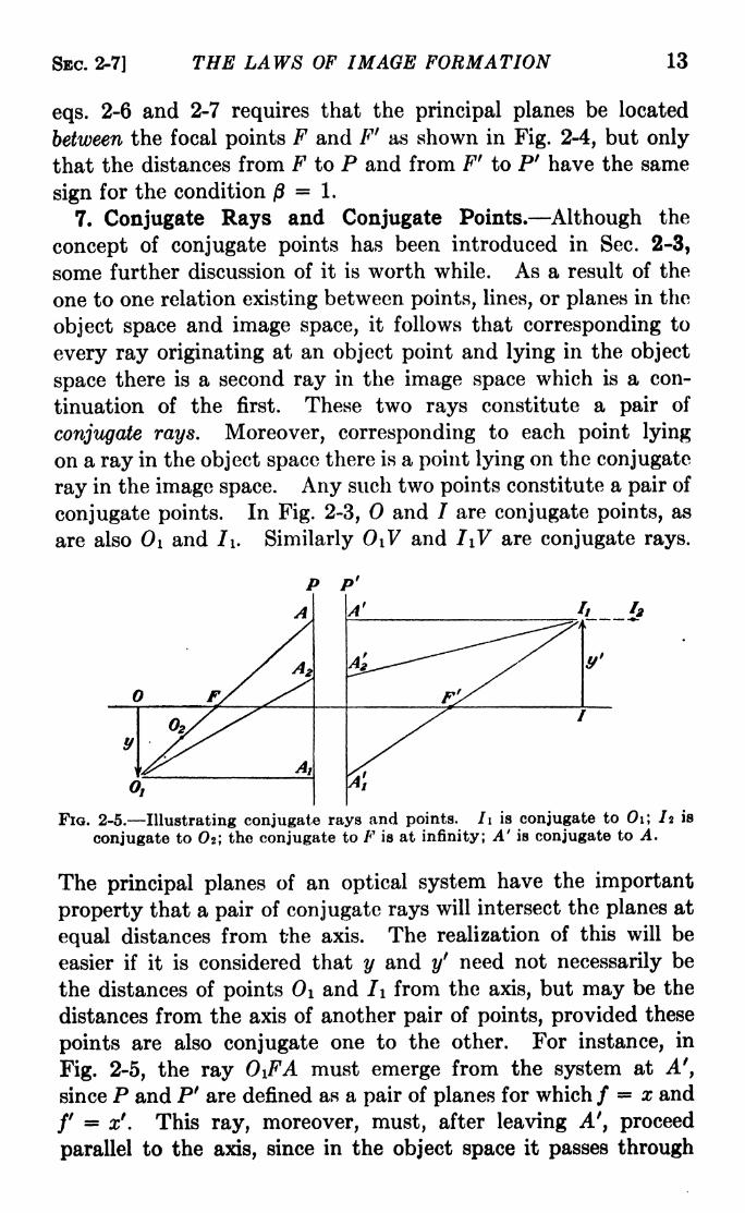
conjugate points. In Fig. 2-3, and / are conjugate points, as
are also 0\ and I\. Similarly 0\V and I\V are conjugate rays.
Fio. 2-5. Illustrating conjugate rays and points. Ii is conjugate to Oil Iz is
conjugate to Of, the conjugate to F is at infinity; A' is conjugate to A.
The principal planes of an optical system have the important
property that a pair of conjugate rays will intersect the planes at
equal distances from the axis. The realization of this will be
easier if it is considered that y and y' need not necessarily be
the distances of points 0\ and /i from the axis, but may be the
distances from the axis of another pair of points, provided these
points are also conjugate one to the other. For instance, in
Fig. 2-5, the ray 0\FA must emerge from the system at A',
since P and P' are defined as a pair of planes for which / x and
f = x'. This ray, moreover, must, after leaving A', proceed
parallel to the axis, since in the object space it passes through

14 LIGHT: PRINCIPLES AND EXPERIMENTS [CHAP. II
F. If the object point were any other point on the line 0\FAexcept Oi, this would still be true. For any other point, such
as Oz, however, the conjugate point in the image space would not
be at /i but at some point such as I2 . Similarly, there will be a
ray Ai'F'Ii conjugate to the ray 0\A\, and a ray A 2'/i conjugateto the ray 0\A^. But for all such pairs of conjugate rays, there
is only one pair of planes for which (3= 1 and these are the
principal planes of the system. In Fig. 2-5 we may see also that
the distances / and /' of these planes from the principal focal
points F and Ff
may be regarded as the principal focal lengths
of the system. A comparison with the definitions of / and /'
given in eqs. 2-2 and 2-3 shows that the principal planes of a
single refracting surface coincide and cut the axis at the vertex
of the surface. It is also evident that only in the case where the
indices of the initial and final media are the same will / =/'.
8. LaGrange's Law. Returning to a further consideration
of Fig. 2-3, it follows that since /' x' = a' and / x a, the
equation for the lateral magnification may be written
ft= y- =^ (2-8)
y
provided the angles <f> and <?' are small. If we consider in addi-
tion a paraxial ray, i.e., one which makes a very small angle with
the axis and lies close to the axis throughout its length, from
to 7, then, putting AV h, we have
h = au =a'u', (2-9)
4
in which u and u' are the angles made by the ray in the object
and image spaces, respectively. Also, for small angles, SnelPs
law may be written
^ = 1. (2-10)<p n
Combining eqs. 2-8 and 2-9, there results
(2-11)y
and from eq. 2-10 it follows that
nyu =n'y'u', (2-12)
SEC. 2-10] THE LAWS OF IMAGE FORMATION 15
which is known as LaGrange's law, and sometimes as the Smith-
Helmholtz law. It may be shown that this law can be extended
to the case of refraction at any number of successive surfaces,
provided y and u are both very small. This is tantamount to an
assumption that the rays under consideration are paraxial rays.
9. Longitudinal Magnification. From elementary considera-
tions, it is evident that for an object of any depth along the a>direc-
tion there will be a corresponding depth in the image. Indicating
these distances by da and da', respectively, we may define the
longitudinal magnification a as the ratio da'/da. By differentia-
tion of eq. 2-5 it follows that
a"2
a = /da (2-13)
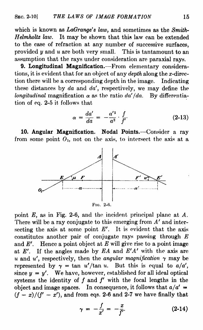
10. Angular Magnification. Nodal Points. Consider a rayfrom some point 0\, not on the axis, to intersect the axis at a
FIG. 2-6.
point E, as in Fig. 2-6, and tho incident principal plane at A.
There will be a ray conjugate to this emerging from A' and inter-
secting the axis at some point E''. It is evident that the axis
constitutes another pair of conjugate rays passing through Eand E'. Hence a point object at E will give rise to a point imageat Ef
. If the angles made by EA and E'A' with the axis are
u and u', respectively, then the angular magnification y may be
represented by 7 = tan w'/tan u. But this is equal to a/a',
since y =y'. We have, however, established for all ideal optical
systems the identity of / and /' with the focal lengths in the
object and image spaces. In consequence, it follows that a/a' =
(/ x)/(f xf
), and from eqs. 2-6 and 2-7 we have finally that
_ _ - _7 ~x7~
f (2-14)
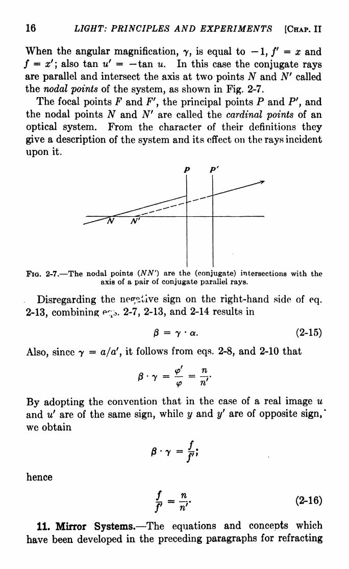
16 LIGHT: PRINCIPLES AND EXPERIMENTS [CHAP. II
When the angular magnification, 7, is equal to 1, /'= x and
/ =x'\ also tan u1
tan u. In this case the conjugate raysare parallel and intersect the axis at two points N and Nf
called
the nodal points of the system, as shown in Fig. 2-7.
The focal points F and Ff
,the principal points P and P', and
the nodal points N and Nfare called the cardinal points of an
optical system. From the character of their definitions they
give a description of the system and its effect on the rays incident
upon it.
P P r
FIG. 2-7. The nodal points (NN r
) are the (conjugate) intersections with theaxis of a pair of conjugate parallel rays.
Disregarding the nep^tive sign on the right-hand side of eq.
2-13, combining PT> 2-7, 2-13, and 2-14 results in
j3= 7 a. (2-15)
Also, since y = a/a', it follows from eqs. 2-8, and 2-10 that
<p' n/3 7 = =
(p n
By adopting the convention that in the case of a real image u
and u' are of the same sign, while y and y' are of opposite sign,'
we obtain
hence
f _n(2-16)
11. Mirror Systems. The equations and concepts which
have been developed in the preceding paragraphs for refracting

SBC. 2-11] THE LAWS OF IMAGE FORMATION 17
surfaces can be used with slight modifications for mirrors. In
Fig. 2-8,
. _ (a-
r) sin p (r-
a') sin psin * -----
g----- =-
p-
,
from which it follows that
(a r) _ (r a')
b P
For paraxial rays, b = a and b' = a' approximately, so that
I + J- = ?.(2-17)a a' r
This is analogous to eq. 2-1. Since
for small angles r = 2/, it follows
that for a mirrorj "j j-a'~j5k--------------a -I------.........\111 k -----r -------
1
- + -3-- (2-18)
The conventions already adopted may be used for the case of
mirrors also. In Fig. 2-8, r is negative, while in the case of a
convex mirror, r would be positive.
Problems
1. Given a lens system for which /= -MO, /' = +8, x =12,
y +6. Using a diagram, find x' and y'.
2. Given an optical system for which / = +10, /'=
16, x = 20,
y = 0. Using a diagram, find x'.
3. How far from a convergent mirror must an object be placed to
give an image four times as large, if the focal length of the mirror is
50 cm.?
4. An object is 1 m. in front of a concave mirror whose radius of
curvature is 30 cm. It is then required to move the image 15 cm.
farther from the mirror. Through what distance must the object be
moved, and which way?5. An object is placed between two plane mirrors which are inclined
at an angle of 60 deg. How many images are formed?
6. What must be the angle between two plane mirrors if a ray inci-
dent on one and parallel to the other becomes after two reflections
parallel to the first?
7. A small bubble in a sphere of glass 5 cm. in diameter appears,
when looked at along the radius of the sphere to be 1.25 cm. from the

18 LIGHT: PRINCIPLES AND EXPERIMENTS [CHAP, II
surface nearer the eye. What is its actual position? If the image of
the bubble is 1 mm. in height, what is its real diameter? What will be
the longitudinal magnification? (Assume n = 1.5)
8. A spherical bowl of liquid has a radius of 10 cm. For what index
of refraction will the focus of the sun's rays be at one side, i.e., at P^Pa7?
9. A spherical bowl of 20 cm. radius is filled with water. What will
be the apparent position of a bubble, seen along a radius, which is
15 cm. from the side of the bowl? What will be the lateral magnifica-tion ? The longitudinal magnification ?
10. What must be the focal length of a lens which will give an imageof the sun 6 in. across?
11. Derive the expression for the longitudinal magnification a from
eq. 2-6, and show that it is the same as given in eq. 2-13.
12. An object lies 250 mm. in front of the incident nodal point of a
lens whose focal length is +60 mm. Where is the image with respect
to the emergent nodal point? Use a diagram in answering the question.

CHAPTER III
COMBINATIONS OF OPTICAL SYSTEMS
1. Equation for a Thin Lens. In Sec. 2-2, by considering the
refraction of rays at a spherical surface, it was found that the
distance a' of an image point on the axis from the vertex of thesurface was related to the distance a of the conjugate object pointfrom the same vertex by eq. 2-1 :
n.
n' n' na a r
in which n is the index of refraction of the medium in the object
space to the left of the surface r, and n' is the index of the mediumof the image space to the right of the surface. Equation 2-1 is
based upon the important hypothesis that the aperture of the
optical system, in this case consisting of a single refracting sur-
face, is small compared to the other dimensions involved. Tworays were considered, one constituting the optical axis, the other
a paraxial ray OAI (Fig. 2-1) incident upon the surface at a
relatively short distance from the axis. To continue this pro-cedure and thus derive a lens formula for an ideal system of morethan one surface, with a distance of any appreciable amountbetween the surfaces, would be extremely cumbersome. It is
relatively easy, however, to obtain the formula for a thin lens.
As the term is used here, a thin lens means one in which the
distance between the surfaces is so small relative to other dimen-
sions that it may be ignored.
In Fig. 3-1, the essential features of Fig. 2-1 are reproduced.The radius of curvature of the first surface is now called r\
and there is added a second surface of radius r2 . Both n and r2
are by convention positive, and the medium to the right of the
second surface has the index n". As in eq. 2-1, the image dis-
tance obtained by refraction at the first surface only is
n n'^_
n' nC*-\\
a am'~
n19

LIGHT: PRINCIPLES AND EXPERIMENTS [CHAP. Ill
where amf
is used for the image distance, to distinguish it from
a', which will be reserved for the image distance for the entire
lens.
With regard to the second surface, the conjugate points Im and/ have the relation of object and image. Hence we may write
an equation analogous to eq. 3-1,
am a
n" - n'(3-2)
the object distance om'for the second surface being negative.
Adding eqs. 3-2 and 3-1, we obtain
n n' n n" n'(3-3)a a r\ r%
If the system is a thin lens in air, n = n" =1, and n' may be
o Iff*
FIG. 3-1.
called n, the index of refraction of the glass, whereupon^eq. 3-3
becomes
. (- -f = (na a TI r2(3-4)
Since by definition the principal focus of a system is that point at
which incident rays parallel to the axis will meet, by the substi-
tution of oo for a in eq. 3-4, a' becomes /, the focal length of the
lens, and the right-hand member of this equation is equal to
i//.
By comparison with eqs. 2-5 and 2-18 it will be seen that the
focal length for any system in air is given by

SBC. 3-2] COMBINATIONS OF OPTICAL SYSTEMS 21
In using eq. 3-4 it is important to remember that r\ and r2 are
positive when the surfaces are convex toward the object. For a
surface concave toward the object, the sign of r must be changed.2. Combinations of Two Systems. Since the equations
developed in Chap. II apply to any ideal optical system, i.e.,
one in which the sizes of the apertures and objects are limited,
they can be used for an ideal system composed of two coaxial
parts. These parts may consist of separate lenses placed
coaxially, of lens and mirror combinations, or of several refracting
surfaces placed coaxially so as to constitute an image-forming
system. It is the purpose here to show how the cardinal points
and equations for the focal length of the combination can be
expressed in terms of the characteristics of the separate parts.
FIG. 3-2.
In Fig. 3-2 is shown a ray passing through two systems having
a common axis. The subscript 1 refers to the first system, the
subscript 2 to the second, and symbols with no subscript to
the combination considered as a single system. As before,
primed symbols refer to the image spaces for the -systems, and
unprimed symbols to the object spaces. In accordance with the
procedure in Sees. 2-3 to 2-10, inclusive, the origins of the systems
will be the focal points. For example, the point FI is the origin
in the object space in the first system, FI is the origin in the
conjugate image space,- and Fris the origin in the image space for
the combination. 'The ray incident to the entire system is
parallel to the optic axis and will consequently pass through
F\ and F'. Let hi = hi represent the distance from the axis
of the intersections of the ray with Pi and Pi, and hj = h^
represent the distance from the axis of its intersections with /Yand P2 . Let A, the separation of the principal focal points FI
and Fz,be positive when there is no overlapping of the inner focal
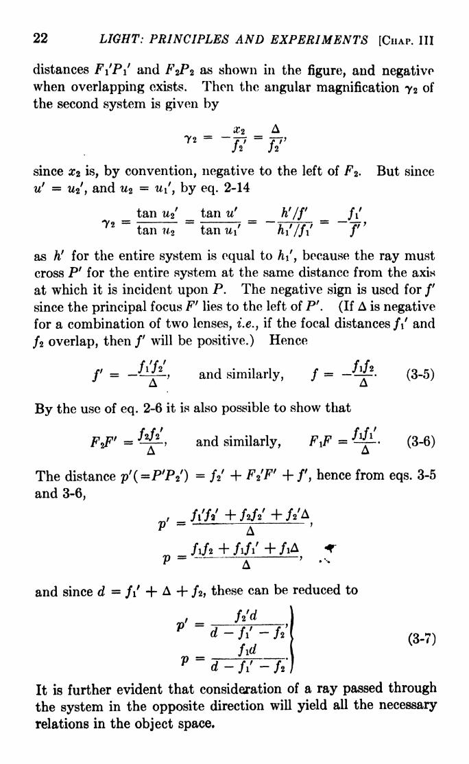
22 LIGHT: PRINCIPLES AND EXPERIMENTS [CHAP. Ill
distances F\P\ and FzPz as shown in the figure, and negativewhen overlapping exists. Then the angular magnification 72 of
the second system is given by
_ 2 _ A72 f i ft'h h
since Xz is, by convention, negative to the left of F* But since
u' = W, and w2= u\, by eq. 2-14
tan u% tan72 =
tan 7*2 tan u\ hi/f\ f
as hf
for the entire system is equal to h\, because the ray must
cross P' for the entire system at the same distance from the axis
at which it is incident upon P. The negative sign is used for /'
since the principal focus F' lies to the left of P'. (If A is negative
for a combination of two lenses, i.e., if the focal distances f\ and
/2 overlap, then /' will be positive.) Hence
f = JlK, and similarly, / = -^2
-
(3-5)
By the use of eq. 2-6 it is also possible to show that
, and similarly, F,F = -'-
(3-6)
The distance p'^PTY) = ft + Ft'F' +f, hence from eqs. 3-5
and 3-6,
A
+ /iA/Y\ - -^^ V -T
P -A
' %
and since d =fi + A -f /2 ,
these can be reduced to
d-fS -
fid(3-7)
It is further evident that consideration of a ray passed through
the system in the opposite direction will yield all the necessary
relations in the object space.

SEC. 3-3] COMBINATIONS OF OPTICAL SYSTEMS 23
For a combination in air of two lenses of focal lengths /i and/2,
/- ?J A d - fi
-/,'
- + - -
{3'8)
or
3. A General Lens Formula. -Methods have been described for
obtaining the characteristics of image formation by refracting sur-
faces, and it has been shown that the fundamental formulas of
ideal lens systems may be obtained by applying the principles
of projective geometry to the optical case. Often it is found
desirable to introduce the concept of the power of a system in
increasing the convergence of the rays incident upon it. A lens
in air is said to have a power of 1 diopter when its focal length is
1 m.; one having a power of 10 diopters has a focal length of
0.1 m. Thus the power (P of a lens in air is the reciprocal of its
focal length in meters.
In a more general case, however, the index of refraction of the
medium into which the rays emerge must be considered. For
example, if light is incident in air upon a lens sealed to the end of
a tube of water, the focal length /' in the water will be greater
than the focal length / in air. A more extreme case would be
that of a lens immersed in a medium of higher index than that of
the glass. In this case the lens, convergent in air, would be
divergent in the medium of higher index. In a divergent system,
i.e., one which decreases the convergence of the rays incident
upon it, the power is a negative quantity.
Using the concept 6f power of convergence described above,
a general lens formula may be obtained. 1 In Fig. 3-3 the shaded
area bounded oAtrfet, right by the surface Si represents a system
upon which light is incident from the left. Let y be the distance
from the axis of a ray parallel to it, and let h be the distance
from the axis at which the ray leaves Si. If the surface S2 were
not present, such rays parallel to the axis would converge to
FQ', and the focal length of the system A to the left of Si would
be /o'. The addition of S2 ,cut by the ray under consideration at
a distance h from the axis, will cause the ray to cross the optical
1 The elegant method here described was originated by Professor C. W.
Woodworth.

24 LIGHT: PRINCIPLES AND EXPERIMENTS [CHAP. Ill
axis at F', and the focal length of the combination will be/7
. Thevalue of fo will depend upon the index of refraction of the mediumbetween the surfaces Si and $2, and the value of /' upon that to
the right of Sz. Hence we may redefine the power of the systemas the index of refraction divided by the focal length; i.e.,
(Po = n/fj and (Pi = n'/f1. Assuming that the aperture is so
small that ho and h may be considered to lie in the surfaces Si
and $2, we get, from similar triangles, to a sufficient degree of
approximation,
h. f i _ h
.
n-'/o -- (3-9)
and
= - - -. (3-10)n i t\Jif vj VJ
But by eq. 2-1 the object and image distances for a single refract-
ing surface are given by
n' n_'a a
In the present case, a' V>J<", and a
3-9 and 3-10
,hence from eqs.
(3-11),kin' - n\
(P = (P + -I )y\ r I
The second term on the right-hand side gives the amount bywhich the power of the system will be changed by the addition

SBC. 3-3] COMBINATIONS OF OPTICAL SYSTEMS 25
of a refracting surface of radius r. There will be a similar term
for every such surface added, hence eq. 3-11 is a recurrent
formula, and for any system may be written
(Pi- h\(ni
- n_Ay)\rT~')' (3-12)
The value of the h at each added surface may be obtained as
follows: In Fig. 3-3
t = ViF' -
where KQ refers to the distance from the axis at which the rays
FIG. 3-4.
emerge from the system A. Substituting in this the value of
/</ from <P = n// ',A- -sT\
(3-13)n
If y is put equal to unity, eq. 3-11 can be simplified to
(Pi= (Pi-i + -(wi
-rii- (3-14)
and, using the general subscript i as before, eq. 3-13 becomes
hi = ftt-i n(3-15)
in which n is the index for the part of the system in which t lies.
The equation for a single lens may now be found. In Fig. 3-4
a lens of index n in air has surfaces of radii n and r2 ,and a thick-
ness between its vertices of t. The power of the first surface is
given by eq. 3-14
(3-16)

26 LIGHT: PRINCIPLES AND EXPERIMENTS [CHAP. Ill
ft
since for parallel light entering the lens (Po = 0, and h\ = y\ = 1.
For the second surface, by eq. 3-15, hz hi --J
>or, substi-
71
tuting the value of (Pi from eq. 3-16,
n ri
Also, by eq. 3-14, (P2 = (Pj H -2
(1 ri), which on substitution7*2
of /i2 from eq. 3-17 and (Pi from eq. 3-16 becomes
n - 1 n - 1 . t (n-
I)2
<P =----1
--- ^-'--
r* r2 n
This is the power of the entire lens, which may be written
<PC = (n-
1)(-- - + -
i-Z_l)= i (3-18)
\ri r2 n r^ / f
For a thin lens in air, t may be put equal to zero, and eq. 3-18
is reduced to the familiar form
= (n- l)i - t. (3-19)
It is frequently desirable to know the distance from the back
face of the lens to the emergent focal point F'. This is given bythe ratio hz/hi
= ///', from which, since hi =1,
' = 2= - . -Z. (3-20)
By means of eq. 3-18 v' can also be expressed in terms of rz
instead of r\.
By methods similar to that above, the equation analogous to
eq. 3-18 for I//, and one analogous to eq. 3-20 for v, may be found.
If the lens system is in air, / =/'. It is evident that, in order
to obtain the focal length of a system, eqs. 3-14 and 3-15 may be
used successively for as many surfaces as there are in the
combination.
4. Classification of Optical Systems. Often a lens or mirror
is designated as convex or concave, according to the shape of its
surface. The difficulty in this usage is that simply the concavity
SEC. 3-5] COMBINATIONS OF OPTICAL SYSTEMS 27
or convexity of the surfaces is not enough to describe the character
of the system. A more useful procedure is to describe a system
by its effect upon the light incident on it, i.e., the convergence or
divergence imposed upon the rays.
Convergent systems can be characterized as dioptric or katop-
tric. The former are those in which the image moves to the right
as the object moves to the right, i.e., toward the lens system,
while the latter are those in which the image moves to the left
as the object moves to the right. Thus it will be seen that a
"double-convex" lens, of index greater than unity, is convergent
and dioptric, since no matter where the object is, as it moves to
the right the image does likewise. On the other hand, a concave
mirror, also convergent, is katoptric since the image moves to the
left as the object moves to the right. A combination of two
such mirrors is dioptric. Hence there is a general rule that a
dioptric system is one composed of one or more refracting sur-
faces, or these combined with an even number of reflections,
while a katoptric system is composed of an odd number of
reflections, or combinations of these with refractions. Similarly,
divergent systems may also be characterized as dioptric or
katoptric.
Since the difference produced in a lens by changing from convex
to concave refracting surfaces is a difference in the signs of the
principal foci, we can classify optical systems as follows:
Convergent: Dioptric :/ positive, /' positive
Katoptric : / positive, /' negative
Divergent: Dioptric : / negative, /' negative
Katoptric -./negative,/' positive
If a lens system is classified according to its power of increasing
the convergence of the rays incident upon it, a convergent system
is said to-be positive, while a divergent lens is negative. A positive
lens may also be defined as one which forms an inverted image
of a distant object.
A simple lens which has a greater thickness between its
vertices than at its rim is convergent, arid one which is thinner is
divergent.
5. Telescopic Systems. In the strict sense of the word a
telescope is a combination of two or more lenses, mirrors, or both,
for the purpose of obtaining magnified images of objects which,
because of their great distance, appear too small for distant

28 LIGHT: PRINCIPLES AND EXPERIMENTS [CHAP. Ill
vision. The term telescope is also employed, however, when a
single lens or mirror of great light-gathering power is used to
enable the observer to photograph images or spectra of distant
objects, such as celestial bodies. In this case no ocular, or eye-
piece, is needed. By telescopic systems as discussed in this
section are meant those combinations of objective and ocular with
which distant objects are observed visually. When the object
is very distant, it can be said to be an infinite distance away,and the image formed by the objective will be at the emergent
principal focus. For best vision this point should also be the
incident principal focus of the ocular, whereupon the rays will be
parallel upon reaching the eye. Thus we have for consideration
a coaxial optical system of two parts for which, as shown in
Fig. 3-5, A = 0.
FIG. 3-5. The principal planes of a telescopic system.
For such a system, the equation xx' =ff' has no meaning,
since x and x' are both infinite, or at least very large comparedto the other dimensions of the system. Consequently the focal
distances / and f for the entire system are also infinite or very
large, and we may choose any pair of conjugate points on the axis
as origins in the object and image spaces. But although the
focal positions of object and image may be distant, the relation
between them is still that of conjugate points. In consequence,
the ratio between x and x' and the lateral magnification will be
finite and definite quantities, and we may write
x' = ax, and y (3-21)
From the first of these may be obtained by differentiation
dx' = a dx, which says that the longitudinal magnification aof a telescopic system is constant. Since A =
0, i.e., since Fjand Fz coincide,
constant. (3-22)

SEC. 3-5] COMBINATIONS OF OPTICAL SYSTEMS 29
Also, as A approaches zero, the limiting value of ///' is, by eqs.
3-6, /i/2//i'/2;
; or, for a telescopic system with the same mediumon both sides,
r
Also, the limiting value of a(=x'/x = FiF'/F\F) is, by eq. 3-6,
given by fzfz/fifi ; or, for a telescope in air,
a = -(3-23)
The angular magnification 7 is also constant for a telescopic sys-
tem. To show this, consider a pair of conjugate rays as shown
in Fig. 3-6. Let (x,y) and (#',?/') be any pair of conjugate points
on these rays. Since any pair of points, A and A', on the axis
FIG. 3-6.
may serve as origins, the tangents of u and u' are respectively
y/x and y'/x'. Thus, by eqs. 2-15, 3-22, and 3-23,
7 - - & (3-24)<x jz
Also, y'u'/yu =|8
2/a. Since for any optical system this ratio
is also equal to i> for a telescope in air a = 2,from which it
follows that 7 = 1/0, or, the reciprocal of the lateral magnifica-
tion has the same numerical value as the angular magnification.
It should be noted that the magnifying power of a telescopic
system, ordinarily obtained by dividing the principal focal
length of the objective by that of the ocular, is the angular, and
not the lateral, magnification.
Problems
1. Using diagrams, locate the principal planes of the lenses havingthe following characteristics:
(a) n = +10, r2= -10, t = 2, n = 1.5
(6) n = -10, r2 +10, t = 2, n 1.5

30 LIGHT: PRINCIPLES AND EXPERIMENTS [CHAP. Ill
(c) ri = oo, r 2= + 10, t = 2, n = 1.5
(d) n = +10, r 2=
oo, t = 1, n = 1.5
(c) n = +5, r 2= +10, J = 1.5, n = 1.5
(/) ri = +10, r 2= +5, =
1.5, n = 1.5.
(Note that f is the d of Fig. 3-2)
2. A sphere of glass has a radius of 10 and an index of 1.5. Usinga diagram, locate all the cardinal points for the separate refracting
surfaces and for the whole sphere.
3. Repeat Prob. 2 above for a hemisphere of glass of the same radius
and index of refraction.
4. An air-glass-water system has the following constants: HI =1,
7i 2=
1.5, n 3=
1.33, r\ = +10, r2=
12, t = 2. Using a diagram,locate all the cardinal points for the separate components and for the
whole system.
5. Using a diagram to scale, locate all the cardinal points of the
separate components and the whole system for the schematic eye givenon page 323.
6. Obtain eq. 3-18 by the relations given in Sec. 3-2. NOTE: makeuse of eqs. 2-2 and 2-3.
7. A luminous point source is on the axis of a convergent lens, and
an image is formed 25 cm. from the lens on the other side. If a second
lens is placed in contact with the first, the image is formed 40 cm. from
the combination and on the same side as the first image. What is the
focal length of the second lens? Consider both lenses to be thin.
8. A bowl of water, spherical in shape, has a radius of 10 cm. Wherewill the focus of the sun's rays be?
9. What is the focal length of a spherical bubble of air suspended in
glycerin if the bubble has a diameter of 2 mm.?10. What will be the focal length of a sheet of glass bent into cylin-
drical form, if the thickness of the glass is 2 cm., the index of refraction
is 1.5, and the radius of the cylinder is 5 m.?
11. Is it possible to have two thin lenses, one divergent, the other
convergent, for which /2=
/i, used together to give an image at a
finite distance? If so, will the image be real or virtual? Discuss all
cases, and illustrate them with diagrams.
12. Using the power formulas of Sec. 3-3, find the focal length of a
doublet made of a double-convex lens of index n\, and a concavo-planelens of index n 2 ,
which are in contact. Let r\ = r*, r3 = r2 . Call the
thicknesses of the two lenses ti and < 2 , respectively.
13. Using the formula derived in the preceding problem, find the
actual focal length of the achromatic doublet calculated in Sec. 6-16,
if instead of being a thin lens, the values of t\ and t 3 are 5 and 3 mm.,
respectively.
CHAPTER IV
APERTURES IN OPTICAL SYSTEMS
1. The Stop. If an object is placed before a simple converginglens the rays which combine to form the image will be only those
which pass through the lens. The rim of the lens thus consti-
tutes the aperture or stop of the optical system. Should the
image be formed by a simple lens and the eye, it is not certain
whether the rays which combine to form the image on the retina
are limited by the rim of the lens or by the iris of the eye. Most
compound systems, such as photographic objectives, telescopes,
microscopes, etc., are provided with circular openings which act
as stops in addition to those which may be due to lens apertures.
In general an optical system has one stop which is in such a.
position that it will, by limiting the rays, improve image forma-
tion as well as provide a restriction on the aperture of the
instrument.
The use of stops is not necessarily to reduce the effects of
faults or aberrations. Even if perfect imagery be assumed, with
coaxial surfaces as in the ideal optical system, restrictions on
aperture may be necessary. For the image must be formed on a
single plane, even if the object has considerable depth. Withmost lens systems, only for points in a given object plane will
there be sensibly point images in a chosen image plane. Points
in object planes nearer to, or farther from, the lens will be repre-
sented by circles of confusion whose dimensions will depend uponthe longitudinal magnification and upon the size of the cone of
rays from the object point through the lens system. Limitingthe extent of this bundle will in general tend to reduce the size
of the circles of confusion and thus improve the performance of
the system.Another effect of stops in certain positions is to limit the
extent of the object field for which an image may be obtained.
2. The Aperture Stop. Consider a simple convergent lens,
thin enough so that it may be represented by a pair of principal31

32 LIGHT: PRINCIPLES AND EXPERIMENTS [CHAP. IV
planes superposed as in Fig. 4-1. Let groups of rays be drawn as
shown. From the laws of image formation it is evident that
rays from the object space crossing at Eythe edge of the stop S,
will give a virtual image of E at E'. It will be seen that E' need
0'
FIG. 4-1. A front stop as aperture stop.
not necessarily be between the object and the lens; its position
along the axis will depend on the character of the image formation
and the position of E. While S limits the bundle of rays passing
to the lens from any point on the object, the rays after refraction
proceed to any point on the image as if limited 1>y stop S1
. The
actual stop S is called the aperture stop of the system, and in the
case described is called a front stop.
3. Entrance and Exit Pupils. A more general case is that of a
combination of systems which may be represented by two thin
convergent lenses as in Fig. 4-2. Here the first lens LI represents
all the component parts lying on the side of the aperture stop S
toward 0, and the second lens Lz, all the components on the side
toward /. Also, LI will give an image of S at some position Si.
This image is called the entrance pupil. Its position may be
found by the ordinary laws of image formation. For instance,
if in Fig. 4-2, is an object position for which S is the aperture
stop of the system, and L\ a simple lens, then the equation
*-|
= _gives the position of the entrance pupil. Here a
a a f
is the distance from LI to S, a' is the distance from L\ to S\, and
/ is the focal length of L\. Similarly, there will be at some posi-
tion Sz an image of S produced by L2 ;this image is called the
exit pupil If an observer looks through the optical system with
his eye in the vicinity of 0, he will see the image of S at a posi-
tion Si, and if he looks through the sysCem with his eye at 7, he
will see the image of S at a position Si. For an extended object,
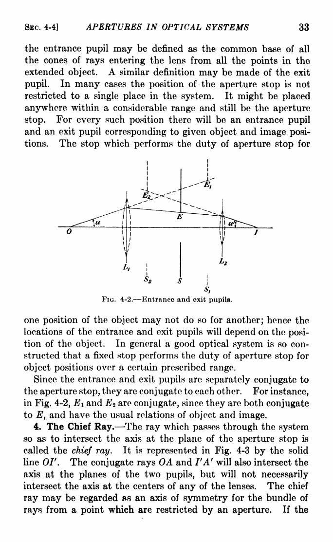
SBC. 4-4] APERTURES IN OPTICAL SYSTEMS 33
the entrance pupil may be defined as the common base of all
the cones of rays entering the lens from all the points in the
extended object. A similar definition may be made of the exit
pupil. In many cases the position of the aperture stop is not
restricted to a single place in the system. It might be placed
anywhere within a considerable range and still be the aperture
stop. For every such position there will be an entrance pupil
and an exit pupil corresponding to given object and image posi-
tions. The stop which performs the duty of aperture stop for
1*1
FIG. 4-2. Entrance and exit pupils.
one position of the object may not do so for another; hence the
locations of the entrance and exit pupils will depend on the posi-
tion of the object. In general a good optical system is so con-
structed that a fixed stop performs the duty of aperture stop for
object positions over a certain prescribed range.
Since the entrance and exit pupils are separately conjugate to
the aperture stop, they are conjugate to each other. For instance,
in Fig. 4-2, Ei and E* are conjugate, since they are both conjugateto E, and have the usual relations of object and image.
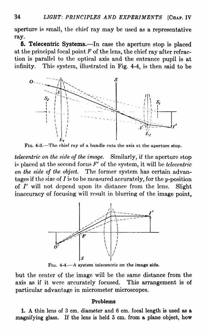
4. The Chief Ray. The ray which passes through the systemso as to intersect the axis at the plane of the aperture stop is
called the chief ray. It is represented in Fig. 4-3 by the solid
line OIf. The conjugate rays OA and I'A' will also intersect the
axis at the planes of the two pupils, but will not necessarily
intersect the axis at the centers of any of the lenses. The chief
ray may be regarded as an axis of symmetry for the bundle of
rays from a point which are restricted by an aperture. If the
34 LIGHT: PRINCIPLES AND EXPERIMENTS [CHAP. IV
aperture is small, the chief ray may be used as a representative
ray.
6. Telecentric Systems. In case the aperture stop is placedat the principal focal point F of the lens, the chief ray after refrac-
tion is parallel to the optical axis and the entrance pupil is at
infinity. This system, illustrated in Fig. 4-4, is then said to be
o...
FIG. 4-3. The chief ray of a bundle cuts the axis at the aperture stop.
telecentric on the side of the image. Similarly, if the aperture stopis placed at the second focus F' of the system, it will be telecentric
on the side of the object. The former system has certain advan-
tages if the size of / is to be measured accurately, for the ^-position
of /' will not depend upon its distance from the lens. Slight
inaccuracy of focusing will result in blurring of the image point,
Fio. 4-4. A system telecentric on the image side.
but the center of the image will be the same distance from the
axis as if it were accurately focused. This arrangement is of
particular advantage in micrometer microscopes.
Problems
1. A thin lens of 3 cm. diameter and 6 cm. focal length is used as a
magnifying glass. If the lens is held 5 cm. from a plane object, how

APERTURES IN OPTICAL SYSTEMS 35
far from the lens must the eye be placed if an area of the object 8 cm.
in diameter is to be seen?
2. A telescope has for its objective a thin positive lens of 20 cm. focal
length and 5 cm. aperture, and for its ocular a thin positive lens of
4 cm. focal length and 2 crn. aperture. Use a diagram and locate the
position and size of the exit pupil, and the size of the field of view.
3. A lens system whose entrance pupil is 25 mm. and exit pupil is
20 mm. in diameter has a principal focal length of +12.5 cm. If an
object whose height is 15 mm. is placed on the axis 30 cm. in front of
the entrance pupil, where is the image, and what is its size?
4. A camera has a thin lens whose aperture is 8 mm. and whose focal
length is 10 cm. What is the //number of the system if a stop 7 mm.in diameter is mounted 5 mm. in front of the lens? If it is mounted5 mm. behind the lens? (The //number, or relative aperture, is the
ratio of the focal length to the entrance pupil of the system.)
6. Two thin lenses are placed 3.5 cm. apart. The first, nearer the
object, has a focal length of +25 cm. and an aperture of 3.5 cm. diame-
ter; the second has a focal length of 30 cm. arid an aperture of 4 cm.
diameter. Which is the aperture stop for an object position 15 cm.
from the first lens? If a stop with a diameter of 2.5 cm. is placed between
them 2 cm. from the first lens, find the location of the aperture stop,
the locations and apertures of the extranco and exit pupils for the object
position given. What is the //number of the system?6. Using a diagram, describe a system which is telecentric on the
side of the object.
CHAPTER V
PHOTOMETRY THE MEASUREMENT OF LIGHT
1. Photometric Standards. The unit of luminous intensity
of a source of light is the candle. If the candle power of a source
is said to be 10, its luminous intensity is 10 candles. Thestandard candle was originally of sperm wax, weighing ^ lb.,
% in. diameter, and burning 120 grains per hr. The primarystandards used in Great Britain, France, and the United States
are specially made carbon filament lamps, operated at 4 watts
per candle. In Germany and some other European countries
the legal standard is the Hefner lamp, which burns amyl acetate
and has an intensity of 0.9 U. S. standard candles when the flame
is at a height of 40 mm. The unit of measurement of the light
flux or flow of radiant energy from a source is the lumen. This is
an arbitrary unit by which the flux is evaluated by its visual
effect, and has the dimensions of power. The quantity of light
radiated in any given direction from a point source of unit
candle power into unit solid angle is 1 lumen. Hence the total
luminous flux from a point source having unit candle power in all
directions is 4w lumens.
A source rarely radiates with the same flux in all directions.
If the actual candle power is /, then the total luminous flux is
given by
/4ir/ rfw. (5-1)
Hence we can define the luminous intensity, measured in candles,
by
/ = (5-2)
If the mean candle power is /, F 4irl.
At a distance r from the source let the light fall on a surface
of area da, which subtends the solid angle rfw at the source, and36

SEC. 5-2] PHOTOMETRY THE MEASUREMENT OF LIGHT 37
whose normal makes an angle with the direction of the light as
shown in Fig. 5-1; then, since the areS, da is given by
J /IT 0\da = ----, (5-3)cos v '
it follows by comparison with eq. 5-2 that
jr. T i Ida cos 6 ,_ . xdF = Jdw = ----3---
(5-4)
The illumination J? on a surface is defined as the flux per unit
area; i.e.,
dF I cos e&=-== -~(o-o)da r2v '
In the metric system the unit of illumination is the lumen per
square meter.
du> _.___
Fi. 5-1.
A simple method for comparing the luminous intensities
(candle powers) of two point sources is at once evident. If two
sources I\ and /2, at distances ri and r2 respectively from a screen
on which the light is incident at the same angle 6, produce on the
screen equal illumination, then
fl=?? (fM})
The experimental determination of equality of illumination
either by the eye or by some auxiliary device is a matter of con-
siderable difficulty. This is especially true when the illumination
is either very faint or very strong, or when the sources do not
have the same color. The measurement of relative illumination
is called photometry. If the measurement takes into account the
wave-length of the light it is called spectrophotometry.f
2. Brightness of Extended Sources. If the source is not a
point, but is of appreciable size, it is customary to speak of its
brightness instead of its intensity. Brightness is denned as the
intensity per unit area of the source, measured in candles per

38 LIGHT: PRINCIPLES AND EXPERIMENTS [CHAP. V
square centimeter in metric units. If B is the brightness, the
intensity in a direction making an angle a with the normal to
the radiating surface is given by
7 = B ds cos a. (5-7)
Substituting in eq. 5-7 the value of 7 given by eq. 5-4, it follows
that the flux through the solid angle subtended by the area da in
Fig. 5-2 receiving the light is
B ds da cos a cos B,
,_ _ x
(5-8)
where is the angle between the normal to da and the direction
of the light. Some luminous surfaces do not radiate uniformlyin all directions, so that rigorously the variation of B with ashould be taken into account. In what follows it is assumed that
B is independent of a.
FIG. 5-2.
The term "brightness" is also used to mean the intensity of
reflection of a diffusely reflecting surface. Such a surface has the
same brightness at every angle of observation. Similarly, a
radiating surface which has the same brightness in every direction
is called a diffusely radiating surface.
Brightness may be measured in lamberls as well as in candles
per square centimeter. The brightness of a perfectly diffusing
surface which radiates or reflects 1 lumen per sq. cm. is 1 lambert.
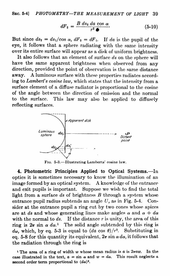
3. Lambert's Cosine Law. Consider a radiating sphere for
which every element of surface has the same brightness. As seen
from a point F, Fig. 5-3, whose distance r away from the sphere
is large compared to the diameter of the sphere, it will appear as a
flat disk. The flux from an element of area ds, at the center of
this disk, falling normally upon an area da at P, will, by eq. 5-8, be
B dsi da
Also, the flux which appears to come from another element of the
same size on the disk will in reality be that from an element ds2
of the sphere, and will be
SBC. 6-4] PHOTOMETRY THE MEASUREMENT OF LIGHT 39
B ds2 da cos a
But since ds2=
rfsi/cos a, e^2= dFi. If rfa is the pupil of the
eye, it follows that a sphere radiating with the same intensityover its entire surface will appear as a disk of uniform brightness.
It also follows that an element of surface ds on the sphere will
have the same apparent brightness when observed from anydirection, provided the point of observation is the same distance
away. A luminous surface with these properties radiates accord-
ing to Lambert's cosine law, which states that the intensity from a
surface element of a diffuse radiator is proportional to the cosine
of the angle between the direction of emission and the normalto the surface. This law may also be applied to diffusely
reflecting surfaces.
Apparent disk
PDistant
point
FIG. 5-3. Illustrating Lamberts' cosine law.
4. Photometric Principles Applied to Optical Systems. In
optics it is sometimes necessary to know the illumination of an
image formed by an optical system. A knowledge of the entrance
and exit pupils is important. Suppose we wish to find the total
light from a surface ds of brightness B through a system whose
entrance pupil radius subtends an angle U, as in Fig. 5-4. Con-
sider at the entrance pupil a ring cut by two cones whose apices
are at ds and whose generating lines make angles a and a -f- da
with the normal to ds. If the distance r is unity, the area of this
ring is 2ir sin a da. 1 The solid angle subtended by this ring is
da, which, by eq. 5-3 is equal to (da cos 0)/r2
. Substituting in
eq. 5-8 for this quantity its equivalent, 2ir sin a da, it follows that
the radiation through the ring is
1 The area of a ring of width w whose mean radius is a is 2iraw. In the
case illustrated in the text, a = sin a and w = da. This result neglects a
second order term proportional to (da)8.

40 LIGHT: PRINCIPLES AND EXPERIMENTS [CHAP. V
dF = 2irB ds da cos a sin a (5-11)
and the total luminous flux through the pupil is
f UFu = 2irB ds I sin a cos a da = irB ds sin2
C7. (5-12)jo
Similarly, if we consider the image ds' of ds to be formed by a
system whose exit pupil has a radius subtending an angle V,corresponding to an entrance pupil of radius U, the luminous
flux through the exit pupil is
FV - irB' ds' sin 2U', (5-13)
where B' is the brightness of the image ds'. Assuming the
da
. 5-4.
transmitting media to be transparent,, *
B ds sin 2 U = B' ds' sin 2 U 1. (5-14)
Because of light absorption and reflection from the lens surfaces,
in actual practice the right-hand member of the equation will be
the smaller of the two.
It can be proved that in a so-called aplanatic system, for a
single position on the axis
ny sin u =n'y' sin u' = constant (5-15)
for any number of media in an optical system. The angles
u and u' are those made with the axis by a pair of conjugate rays;
hence they can be identified with U and U'tthe rim rays to the
boundaries of the entrance and exit pupils. In eq. 5-14, since
ds and ds' are elements of area, we may write
and consequently,
* _ (y.\*t
~v/
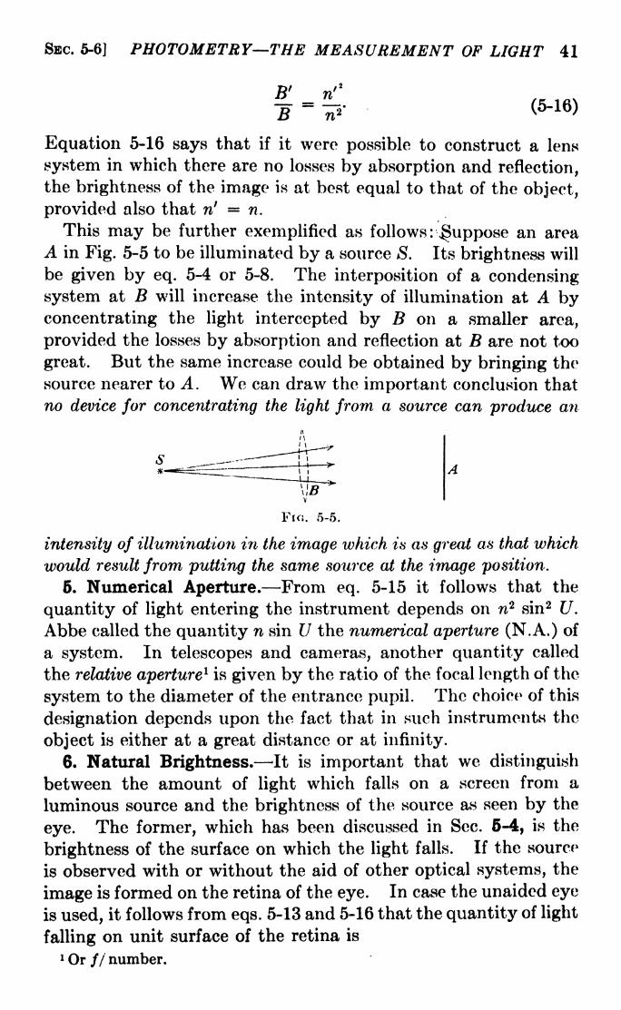
SBC. 5-6] PHOTOMETRY THE MEASUREMENT OF LIGHT 41
B' w'2
~B=
~tf'(5~16>
Equation 5-16 says that if it were possible to construct a lens
system in which there are no losses by absorption and reflection,the brightness of the image is at best equal to that of the object,
provided also that n' n.
This may be further exemplified as follows : ^uppose an area
A in Fig. 5-5 to be illuminated by a source <S. Its brightness will
be given by eq. 5-4 or 5-8. The interposition of a condensing
system at B will increase the intensity of illumination at A byconcentrating the light intercepted by B on a smaller area,
provided the losses by absorption and reflection at B are not too
great. But the same increase could be obtained by bringing the
source nearer to A. We can draw the important conclusion that
no device for concentrating the light from a source can produce an
Fio. 5-5.
intensity of illumination in the image which is as great as that which
would result from putting the same source at the image position.
6. Numerical Aperture. From eq. 5-15 it follows that the
quantity of light entering the instrument depends on rc2 sin2 U.
Abbe called the quantity n sin U the numerical aperture (N.A.) of
a system. In telescopes and cameras, another quantity called
the relative aperture1is given by the ratio of the focal length of the
system to the diameter of the entrance pupil. The choice of this
designation depends upon the fact that in such instruments the
object is either at a great distance or at infinity.
6. Natural Brightness. It is important that we distinguish
between the amount of light which falls on a screen from a
luminous source and the brightness of the source as seen by the
eye. The former, which has been discussed in Sec. 5-4, is the
brightness of the surface on which the light falls. If the source
is observed with or without the aid of other optical systems, the
image is formed on the retina of the eye. In case the unaided eye
is used, it follows from eqs. 5-13 and 5-16 that the quantity of light
falling on unit surface of the retina is
1 Or // number.
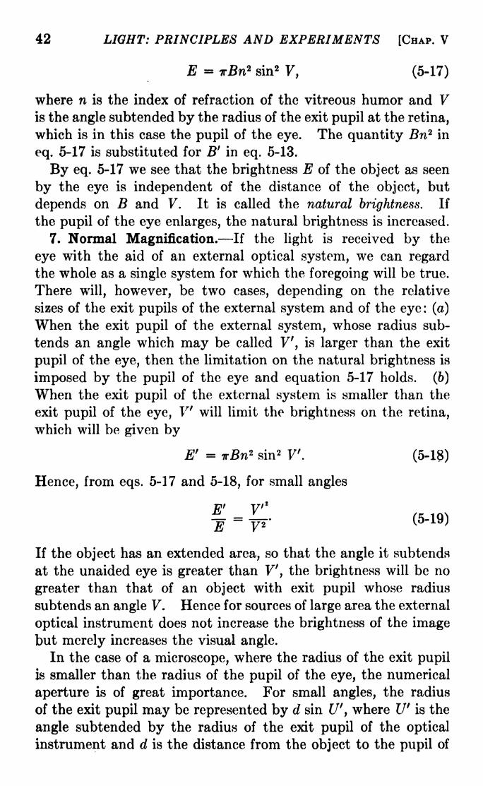
42 LIGHT: PRINCIPLES AND EXPERIMENTS [CHAP. V
E - TrBn2 sin2F, (5-17)
where n is the index of refraction of the vitreous humor and Vis the angle subtended by the radius of the exit pupil at the retina,
which is in this case the pupil of the eye. The quantity Bn2 in
eq. 5-17 is substituted for B f
in eq. 5-13.
By eq. 5-17 we see that the brightness E of the object as seen
by the eye is independent of the distance of the object, but
depends on B and V. It is called the natural brightness. If
the pupil of the eye enlarges, the natural brightness is increased.
7. Normal Magnification. If the light is received by the
eye with the aid of an external optical system, we can regard
the whole as a single system for which the foregoing will be true.
There will, however, be two cases, depending on the relative
sizes of the exit pupils of the external system and of the eye : (a)
When the exit pupil of the external system, whose radius sub-
tends an angle which may be called V, is larger than the exit
pupil of the eye, then the limitation on the natural brightness is
imposed by the pupil of the eye and equation 5-17 holds. (6)
When the exit pupil of the external system is smaller than the
exit pupil of the eye, V will limit the brightness on the retina,
which will be given by
E' = T#n2 sin 2 V. (5-18)
Hence, from eqs. 5-17 and 5-18, for small angles
E' F'*
If the object has an extended area, so that the angle it subtends
at the unaided eye is greater than F', the brightness will be no
greater than that of an object with exit pupil whose radius
subtends an angle F. Hence for sources of large area the external
optical instrument does not increase the brightness of the imagebut merely increases the visual angle.
In the case of a microscope, where the radius of the exit pupil
is smaller than the radius of the pupil of the eye, the numerical
aperture is of great importance. For small angles, the radius
of the exit pupil may be represented by d sin Ur
,where V is the
angle subtended by the radius of the exit pupil of the optical
instrument and d is the distance from the object to the pupil of

SEC. 6-8] PHOTOMETRY THE MEASUREMENT OF LIGHT 43
the eye, the latter being placed at the exit pupil of the instrument.
If h is used for the radius of the pupil of the eye, then
E' _ d* sin* V~E--
T?--
(5'20)
Here E is the brightness without, and E' is that with, an external
instrument. By eq. 5-15, it follows that
sin2 V = . sin2 V.n' y'
Since y' /y2 =
|32,where /3 is the lateral magnification, eq. 5-20
may be written
E' _ dV sin* U~E
-
whence, since n2 sin2 (/= [N.A.]2,
it follows that E'/E is pro-
portional to the square of the numerical aperature. Hence for
the greatest brightness E' it is necessary to have as large a
numerical aperture as possible. Also, for a numerical apertureof a certain size it is possible to have a magnification such that
E' equals the natural brightness E. A magnification of this
amount is called the normal magnification.
8. Effects of Background. For point sources and those of
very small area, the foregoing rules do not hold, principally
because of departures from the laws of rectilinear propagation.
When small angular apertures such as that of the eye are used,
diffraction plays an important part. Roughly speaking, the size
of the image of a point source on the retina depends inversely on
the size of the pupil of the eye. When a star is seen with the
unaided eye, the light enters an area irhz
',if with a telescope, the
light enters an area ira*, where a is the radius of the telescope
objective. If the exit pupil of the telescope is less than or equal
to the pupil of the eye, all the light passing through the objective
enters the eye. Hence the effect on the retina will be an increase
on the brightness of the star in the ratio a2/A 2
,where A is the
radius of the exit pupil of the telescope. If the exit pupil of the
telescope is greater than h, not all of the light enters the eye, and
in this case the increased brightness will be a2/h
2 times that with
the unaided eye. In either case, there will be an increase in the
44 LIGHT: PRINCIPLES AND EXPERIMENTS [CHAP. V
brightness of the starlight. On the other hand, as shown in
Sec. 6-7, the brightness of the background of the sky is not
increased. If the magnification is greater than the normal
magnification, it may even be diminished. Thus, with a telescope
we can see stars of smaller luminosity than with the naked eye,
even when a considerable amount of skylight is present. If
nearby objects are viewed, the length of the telescope must be
small in comparison to the distance of the object for an increase
of brightness to be obtained.
In dealing with vision, the physiological aspects should not be
neglected. Especially in the case of persons who are color-blind
or partly so, objects of different sizes differ in their visibility.
The effects of irradiation must also be taken into account. From
the bottom of a deep shaft stars can be seen even in broad day-
light. Here the starlight has not been reduced, neither has the
brightness of the sky, but merely the total light sent into the
eye from the whole sky. Objects not distinguishable in a dim
light may be seen more easily by restricting the vision to those
objects by masking off the light of nearby brighter areas. Irradi-
ation of the eye by ultraviolet light from an otherwise invisible
source will also serve to obscure the vision of surrounding objects.
The aperture of an optical instrument also serves to limit the
ability to see separately objects which are close together, i.e., it
determines the resolving power of the instrument. The sub-
ject of resolving power will be discussed in the chapter on
diffraction.
Problems
1. Find two points on the straight line joining two sources where the
illumination is the same. The sources are 20 candle power and 30 candle
power, respectively, and are 300 cm. apart.
2. A simple lens having a diameter of 8 cm. and a focal length of
25 cm. is used to focus the light of the sun on a white screen. What is
the ratio of the brightness of the image to the brightness when the screen
is illuminated by the sunlight without the use of a lens?
3. A lamp whose intensity is 75 candles is placed 300 cm. from a
screen whose reflecting power is 70 per cent. If the screen is a diffuse
reflector, what is its brightness in candles per cm. 2? In lamberts?
4. Why does a celestial telescope enable us to see stars brighter by
contrast with the background of the sky?

CHAPTER VI
ABERRATIONS IN OPTICAL SYSTEMS
There are five aberrations, or faults, in ordinary lens or mirror
systems, which are due to the shapes of the surfaces employed,the relative positions of the stops, or the position of the object:
spherical aberration, astigmatism, coma, curvature of the irnag^
field, and distortion of the image. To these may be added, for
lenses but not mirrors, the fault called chromatic aberration,
which is due to the variation of index of refraction of transparentsubstances with color. Spherical and chromatic aberration occur
even in the case of point objects on the axis of a lens system,while the other four astigmatism, coma, curvature of the field,
and distortion occur in the case of point objects off the axis.
If the angle made by any ray with the axis is u, the assumptionhas been made in the theory of ideal optical systems that
sin u = u. This assumption leads to the so-called first-order
theory. The expansion of sin u into a series results in
U 1.
//. ,\sm u = ug-j
-f ^ ^TJ+ (6-1)
The extent of the departure from ideal theory depends upon the
extent to which terms in odd orders of u must be added; this in
turn depends either upon the size of the aperture of the lens, or
the distance of the object point from the axis, or both. The
rigorous mathematical analysis of these aberrations to the third
and higher orders has been made the subject of a great deal of
study. Indeed, the subject is one still engaging the attention of
specialists in the field of optics, and a great deal of progress is
being made in the development of new methods for reducingthese aberrations to a minimum in optical systems. Althoughthe subject is one which is too extensive to be mastered by anybut highly trained specialists, the fundamental ideas involved
are relatively simple.46

46 LIGHT: PRINCIPLES AND EXPERIMENTS [CHAP. VI
The most comprehensive analysis of the five aberrations wasmade by von Seidel, who developed a group of five terms for their
correction. 1 These terms are to be applied to first-order theoryfor ideal optical systems to take into account the third-order
corrections for rays making appreciable angles with the axis.
When the oblique rays fulfill the same conditions as the paraxial
rays, the terms become zero. However, the equations thus
obtained cannot be solved explicitly for the radii of curvature of
the refracting surfaces, so that in practice it is more expedient
to trace the path of each ray through the optical system and in
this manner find the appropriate surface curvatures for the reduc-
tion of the aberrations to the required degree.
( 1. Spherical Aberration. The equations for refraction in ideal
optical systems given in Chap. II were derived on the assumption
FIG. 6-1. Illustrating spherical aberration.
that the aperture of the refracting surface was sufficiently small
so that distances from the object to points on the surface could
be considered equal. This was also assumed with regard to
distances from the image to the refracting surface. For any
optical system, the departure from this equality will depend on
the size of the aperture used. On refraction at a spherical sur-
face, as the ratio of aperture to focal length is increased, the
rim rays, i.e., those which are refracted at the boundary of the
surface, will converge to an image point considerably closer to
the surface than will the paraxial rays, which are those lying
extremely close to the axis throughout their lengths. The
point /' in Fig. 6-1, to which the paraxial rays converge, is called
the Gaussian image point. Each rim ray extended beyond the
1 A simple treatment of the von Seidel equations is given in Whittaker's
"Theory of Optical Instruments."

SBC. 6-1] ABERRATIONS IN OPTICAL SYSTEMS 47
axis cuts the caustic (the envelope of all rays of different slopes)
at N, where the diameter of the circular cross section of the entire
bundle of rays has its minimum value in the range from L to /'.
This area is called the least circle of aberration. It can be reduced
in size by diminishing the aperture, at the expense of illumination,
by changing the shape of the surface, or by combining several
refracting surfaces which mutually compensate for the aberration.
The last two methods may introduce other defects in the image,so that in most cases a compromise must be effected which will
yield the result most satisfactory for the purpose of the particular
optical system.
(a) (b)
Fia. 6-2. Demonstration of the effect of spherical aberration in a single lens,
(a) is a photograph of a screen, (b) is a photograph taken of a point source of
monochromatic light with the lens covered by the screen. The photographic
plate was placed at the Gaussian image point. Only the rays through the large
central hole in (a) are in focus in (b).
An excellent illustration of spherical aberration can be made
with an ordinary plano-convex lens. Figure 6-2a is a photograph
of an opaque screen having a hole in the middle and smaller
holes in zones at different distances from the axial position.
With this screen placed over the lens and a point of light about
1 mm. in diameter as a source, the photograph in Fig. 6-26 was
made. A filter was used to render the light nearly mono-
chromatic. The image at the center corresponds to the Gaussian
image point and is formed by the rays through the central hole.
The rings of images about this point show the rapid increase of
spherical aberration for zones of larger radius. If the screen were
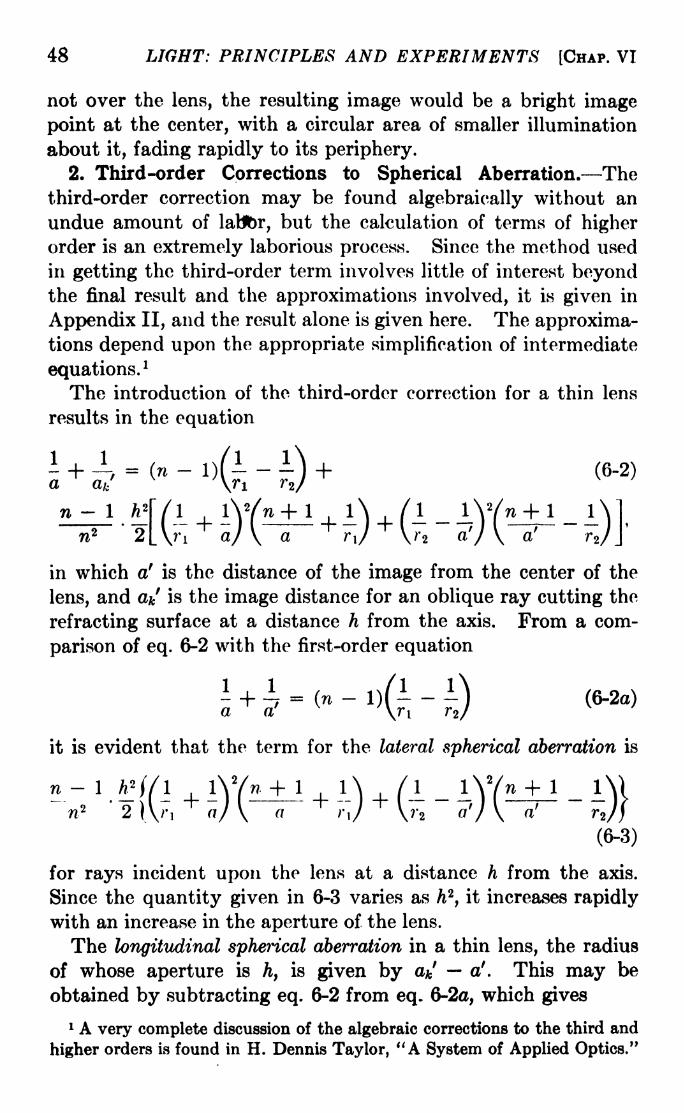
48 LIGHT: PRINCIPLES AND EXPERIMENTS [CHAP. VI
not over the lens, the resulting image would be a bright image
point at the center, with a circular area of smaller illumination
about it, fading rapidly to its periphery.
2. Third-order Corrections to Spherical Aberration. Thethird-order correction may be found algebraically without an
undue amount of labor, but the calculation of terms of higherorder is an extremely laborious process. Since the method used
in getting the third-order term involves little of interest beyondthe final result and the approximations involved, it is given in
Appendix II, and the result alone is given here. The approxima-tions depend upon the appropriate simplification of intermediate
equations.1
The introduction of the third-order correction for a thin lens
results in the equation
a ak,. (_,)(!-!)+ (6-2)
n 1 htf ( 1 l\Yn + 1 1\ /I 1
w*~~'
~2\ \7 a/ V a F/ \r a7
in which a' is the distance of the image from the center of the
lens, and a*/ is the image distance for an oblique ray cutting the
refracting surface at a distance h from the axis. From a com-
parison of eq. 6-2 with the first-order equation
- + -^ = (n-
l)(---} (8-2o)
a a' '\ri r2/
it is evident that the term for the lateral spherical aberration is
n -1 A* //I 1\Y + 1 1\ /I lV/n + 1 l
"n'
2 )V,+
a) \~^T+7j
+\Tt
~J) \~J~
~7(6-3)
for rays incident upon the lens at a distance h from the axis.
Since the quantity given in 6-3 varies as h2,it increases rapidly
with an increase in the aperture of the lens.
The longitudinal spherical aberration in a thin lens, the radius
of whose aperture is ht
is given by a*' a'. This may be
obtained by subtracting eq. 6-2 from eq. 6-2a, which gives
1 A very complete discussion of the algebraic corrections to the third and
higher orders is found in H. Dennis Taylor, "A System of Applied Optics."

SBC. 6-3] ABERRATIONS IN OPTICAL SYSTEMS 49
where [S.A.] is written for the lateral spherical aberration, or,
ak' - a' = -a
If the difference between a' and a*/ is not too great, the last
equation may be written
ak' - a
1 = -' 2[S.A.].
This is the difference between the focal lengths of the rim raysand paraxial rays. In using these equations, it should be remem-bered that by convention the radius r2 of the second surface of a
double-convex lens is negative.
3. Coddington's Shape and Position Factors. Coddingtonhas obtained an expression for the spherical aberration of a thin
lens in terms of two quantities which we may denote by s and p,
factors representing respectively the "shape" of the lens and the
position of the object. The values of these factors in terms of
known constants are stated as follows: In the first-order equationfor a simple lens, eq. 6-2a, let
1 _ (1 + p) I _ (1 -p)a
"
~2f'
a' 2f""'
n 2/(n-
1) r, 2f(n- 1)
Substituting these in 6-3, the lateral aberration becomes
(3n
Differentiating with respect to s, we obtain
d[S.A.] _ h* \2(n + 2)8 + 4(n -l)(n + I)p1
"~5T""V5
'
I ^^T)rJ'
which becomes zero when
(6-6)
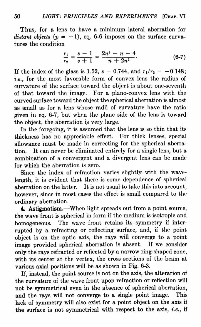
50 LIGHT: PRINCIPLES AND EXPERIMENTS [CHAP. VI
Thus, for a lens to have a minimum lateral aberration for
distant objects (p=
1), eq. 6-6 imposes on the surface curva-
tures the condition
r\ _ s 1 _ 2w* n 4
r^
~7+~I n + 2w2
'
If the index of the glass is 1.52, s = 0.744, and n/r2= -0.148;
i.e., for the most favorable form of convex lens the radius of
curvature of the surface toward the object is about one-seventh
of that toward the image. For a plano-convex lens with the
curved surface toward the object the spherical aberration is almost
as small as for a lens whose radii of curvature have the ratio
given in eq. 6-7, but when the plane side of the lens is toward
the object, the aberration is very large.
In the foregoing, it is assumed that the lens is so thin that its
thickness has no appreciable effect. For thick lenses, special
allowance must be made in correcting for the spherical aberra-
tion. It can never be eliminated entirely for a single lens, but a
combination of a convergent and a divergent lens can be made
for which the aberration is zero.
Since the index of refraction varies slightly with the wave-
length, it is evident that there is some dependence of spherical
aberration on the latter. It is not usual to take this into account,
however, since in most cases the effect is small compared to the
ordinary aberration.
4. Astigmatism. When light spreads out from a point source,
the wave front is spherical in form if the medium is isotropic and
homogeneous. The wave front retains its symmetry if inter-
rupted by a refracting or reflecting surface, and, if the point
object is on the optic axis, the rays will converge to a point
image provided spherical aberration is absent. If we consider
only the rays refracted or reflected by a narrow ring-shaped zone,
with its center at the vertex, the cross sections of the beam at
various axial positions will be as shown in Fig. 6-3.
If, instead, the point source is not on the axis, the alteration of
the curvature of the wave front upon refraction or reflection will
not be symmetrical even in the absence of spherical aberration,
and the rays will not converge to a single point image. This
lack of symmetry will also exist for a point object on the axis if
the surface is not symmetrical with respect to the axis, i.e., if

SEC. 6-5] ABERRATIONS IN OPTICAL SYSTEMS 51
it is not a surface of revolution about the axis. In either case,
the resulting image will be astigmatic, and the cross sections of
the wave front at positions near the focus will be as shown in
Fig. 6-4. When astigmatism is present, there are two line foci
at right angles to each other, while the closest approach to a
point image is a circular patch or confusion of light between them.
Sometimes a distinction is made between the astigmatism pro-
duced by oblique rays, as described above, and that produced by
OOo o_
image point
FIG. 6-3. Showing the shapes of stigmatic bundles before and behind the imagepoint.
the refraction or reflection by cylindrical surfaces. In the latter
case, there is merely one focal position, so that the image of a
point source is drawn out into a line parallel to the axis of the
cylinder. For simplicity, only the first case will be discussed,
as it is more definitely classified as an aberration.
5. Primary and Secondary Foci. The two line foci shown in
Fig. 6-4 are known as the primary and secondary foci, the former
0>o> - o O
Fio. 6-4. Showing the shapes of astigmatic bundles before and behind the two
astigmatic line images of a point object.
being nearer to the system in the illustration. The primary
focus is sometimes called the meridional and sometimes the
tangential focus, while the secondary is sometimes called the
sagittal focus.
The equations giving the distances from a single refracting
surface to the two astigmatic image positions are derived in
Appendix III. They are, for the primary and secondary foci,
respectively,
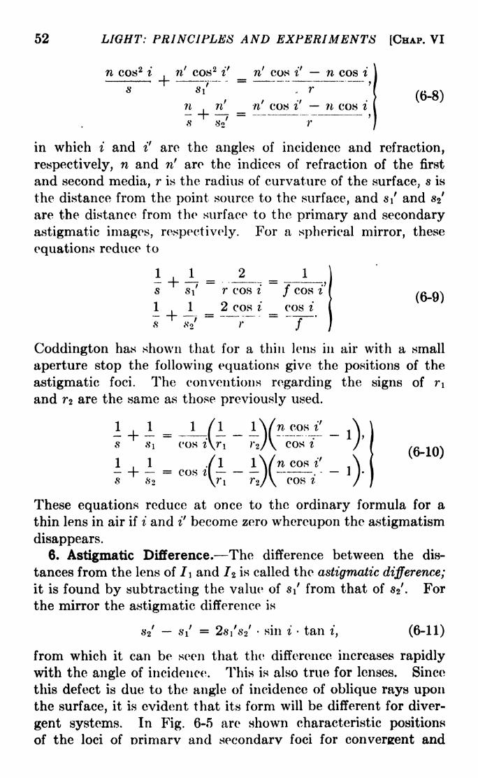
52 LIGHT: PRINCIPLES AND EXPERIMENTS [CHAP. VI
n cos 2 i,
n' cos 2i' n' cos i' n cos i
s Si - r
?i n' _ -n7
cos i' n cos i
8 so' r
(6-8)
in which i and i7
are the angles of incidence and refraction,
respectively, n and n' are the indices of refraction of the first
and second media, r is the radius of curvature of the surface, is
the distance from the point source to the surface, and s\ and 8%
are the distance from the surface to the primary and secondary
astigmatic images, respectively. For a spherical mirror, these
equations reduce to
(6-9)
Coddington has shown that for a thin lens in air with a small
aperture stop the following equations give the positions of the
astigmatic foci. The conventions regarding the signs of r\
and TZ are the same as those previously used.
l + i = .JJl _ lY."-^ _ As i cos i\r\ t'z/ \ cos t /
1,1 /I iVncosi' A= cos il II . II-&2 \?"i r2/\ COS ? /
(6-10)
These equations reduce at once to the ordinary formula for a
thin lens in air if i and i' become zero whereupon the astigmatism
disappears.
6. Astigmatic Difference. The difference between the dis-
tances from the lens of I\ and 1% is called the astigmatic difference;
it is found by subtracting the value of i
7 from that of s27
. For
the mirror the astigmatic difference is
Si7 = 2si
7s 2
7sin i tan i, (6-11)
from which it can be seen that the difference increases rapidly
with the angle of incidence. This is also true for lenses. Since
this defect is due to the angle of incidence of oblique rays uponthe surface, it is evident that its form will be different for diver-
gent systems. In Fig. 6-5 are shown characteristic positions
of the loci of orimarv and secondary foci for convergent and
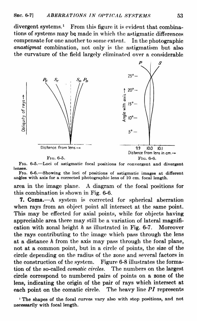
SBC. 6-7] ABERRATIONS IN OPTICAL SYSTEMS 53
divergent systems.l From this figure it is evident that combina-
tions of systems may be made in which the astigmatic differences
compensate for one another to some extent. In the photographicanastigmat combination, not only is the astigmatism but also
the curvature of the field largely eliminated over a considerable
P S
o>*>
JQO
PC Sc25-
f20-
*Xcs
15-i
en ,^o
Distance from lens - 9.9 10.0 10.1
Distance from lens in cm.-
FIG. 6-5. FIG. 6-6.
FIG. 6-5. Loci of astigmatic focal positions for convergent and divergentlenses.
FIG. 6-6. Showing the loci of positions of astigmatic images at different
angles with axis for a corrected photographic lens of 10 cm. focal length.
area in the image plane. A diagram of the focal positions for
this combination is shown in Fig. 6-6.
7. Coma. A system is corrected for spherical aberration
when rays from an object point all intersect at the same point.
This may be effected for axial points, while for objects having
appreciable area there may still be a variation of lateral magnifi-
cation with zonal height h as illustrated in Fig. 6-7. Moreover
the rays contributing to the image which pass through the lens
at a distance h from the axis may pass through the focal plane,
not at a common point, but in a circle of points, the size of the
circle depending on the radius of the zone and several factors in
the construction of the system. Figure 6-8 illustrates the forma-
tion of the so-called comatic circles. The numbers on the largest
circle correspond to numbered pairs of points on a zone of the
lens, indicating the origin of the pair of rays which intersect at
each point on the comatic circle. The heavy line PI represents
1 The shapes of the focal curves vary also with stop positions, and not
necessarily with focal length.

54 LIGHT: PRINCIPLES AND EXPERIMENTS [CHAP. VI
the chief ray of the bundle. Each zone of the lens produces a
comatic circle, the radius increasing as h increases. The centers
of the comatic circles will also be displaced, either toward or
FIG. 6-7. Illustrating pure coma.
away from the axis. In the case illustrated, the resulting flare of
the pear-shaped image is away from the axis, and the coma is said
to be positive. If the flare is nearer the axis than the image point
of the chief ray, the coma is negative.
Fio. 6-8. The formation of comatic images. Pairs of rays from a given zone,such as 1 and 1, 2 and 2, etc., meet at points not common to all rays, but lying ona comatic circle whose distance from the axis varies with the radius of the zone.
Since the condition which results in coma is a difference of
lateral magnification for rays passing through different zones of a
lens, the constancy of y'/y for all zones will result in its elimina-
tion. It can be shown that provided y' and y are small distances
in the object and image planes,

SBC. 6-9] ABERRATIONS IN OPTICAL SYSTEMS 55
n'y' sin u' = ny sin u, (6-12)
where u and u' are the angles between conjugate rays and the
axis. 1 Hence the magnification will be constant and coma will be
absent, provided sin u'/sin. u is constant. This is known as
Abbe's sine condition. For small angles u and u', it is the sameas LaGrange's law.
Figure 6-9 is a photograph of a region of the sky taken with a
24-in. reflecting telescope. The effect of coma shows in stellar
images which are some distance from the center of the field.
For a very distant object near the axis coma will be absent if
r--.= constant. (6-13)
sin u ^ '
This equation is easily derived from eq. 6-12.
8. Elimination of Coma. It can be shown that the condition
for no coma, i.e., the sine condition, can also be stated in the
terminology of Coddingtoii as
s(2n + l)(n-
1) + (n + l)p =0, (6-14)
in which s and p are, respectively, the shape factor and the position
factor as before. Since this equation is linear in s, it is possible
to eliminate coma entirely from a lens system for a single object
position. A lens system which is corrected for both spherical
aberration and coma for a single object position is called aplanatic.
It can be shown 2 that the condition for no spherical aberration
for two positions P\ arid P- of the object, when they are near
each other on the axis, is
sin 2
where Pz and Pi are the images of P 2 and PI. Since this con-
dition and the sine law cannot be true at the same time, an optical
system cannot be made aplanatic for more than one position of
the object.
9. Aplanatic Points. Two points on the axis which have the
property that rays proceeding from one of them shall all con-
verge to, or appear to diverge from, the other are called aplanatic
1 For a simple proof of the sine law, see Drude, "Theory of Optics," pp.
58 and 505, in the English translation.
2 See Drude, "Theory of Optics," p. 62 of the English translation.

56 LIGHT: PRINCIPLES AND EXPERIMENTS [CHAP. VI
o

SEC. 6-9] ABERRATIONS IN OPTICAL SYSTEMS 57
points. A useful device for describing their properties, originallydiscovered by Thomas Young, although later independentlydiscussed by Weierstrass, is illustrated in Fig. 6-10. Light froma medium of index n is refracted at a spherical surface into a
medium of index n'. The surface is given by a circle drawn
FIG. 6-10. Young's construction for refraction at a spherical surface.
concentrically with two circles whose radii are equal to rn/n'
and rn'/n, where r is the radius of curvature of the surface. The
projection of an incident ray cuts the larger circle at point M,and
a line drawn from M to the center C cuts the smaller circle at AT.
FIG. 6-11. Axial aplanatic points in refraction.
A straight line from the point of incidence A through AT is the
refracted ray. The construction of a few such rays, incident on
the surface at different distances from the axis, will readily illus-
trate that they cannot intersect in a single given point. If how-
ever, the points M and N are on the axis, as illustrated in

58 LIGHT: PRINCIPLES AND EXPERIMENTS [CHAP. VI
Fig. 6-11, the refracted rays will all meet at N. Conversely, if
rays originate at N, after refraction they will appear to come from
a virtual source M. In this case the points M and N are called
aplanatic points of the refracting surface. They have the prop-
erty that rays originating at one of them will be refracted so as to
pass through or be projected back through the other. These
points have an important practical application in the construc-
tion of microscope objectives. As illustrated in Fig. 6-12, the
lens closest to the object is made hemispherical, with the flat
surface near the object. Light from P, the object position, will
be refracted so that there will be a virtual image at P'. Themedium between P and the spheri-
cal surface is made practically con-
tinuous by immersing the object in
an oil of index of refraction about
the same as that of the glass.
The lateral magnification of the
image at P' will be P'V/PV. If a
second lens Lz is added in the form
of a meniscus with its concaveFIG. 6-12. The principle of
aplanatic points applied to a micro-spherical surface having a center of
scope objective.r
, .,, ,
curvature at P,there will be a
second refraction at the rear, convex, surface, giving rise to a vir-
tual image at P" with a second lateral magnification. There is a
limit to which the magnification can be repeated in this manner,
because of the introduction of chromatic aberration.
An aplanatic refracting surface has the equation
na n'a' = constant,
in which a and a' are the distances from the object and image,
respectively, to the surface. This is the equation of a Cartesian
oval. For an aplanatic reflecting surface, the equation is
a a' = constant. This is the equation of an ellipsoid of
revolution about the line joining the object and image points.
10. Curvature of Field. It has been shown that for an object
point not on the axis there are two line or astigmatic foci. If
the object is an extended plane, the astigmatic images will not
be planes, but curved surfaces. For object points on or near
the axis, there will be sharp point-to-point representation in the
image plane, but as the distance from the axis is increased, the

SBC. 6-10] ABERRATIONS IN OPTICAL SYSTEMS 59
sharpness of the image will decrease. Instead, each point of
the object will be represented by a blurred patch, the size of whichwill be greater for greater distances from the axis. Even if the
defects of spherical aberration, astigmatism, and coma are cor-
rected, this patch will be a circle of confusion and will be the
closest approach possible to a sharp-point focus. The surface
containing this best possible focus for all parts of the image will
not be a plane, but a surface of revolution of a curved line aboutthe axis. This defect is known as curvature of the field. Thecondition for its removal was first stated by Petzval. While this
condition may be applied to systems composed of a number of
lenses, for a pair of thin lenses in air it reduces to
=0- (6-15)
For a convergent combination in which /i is the focal lengthof the positive, and fz is the focal length of the negative com-
ponent, /2 must be greater than f\. Therefore, in order that
eq. 6-15 may be satisfied, it is necessary that n2 be less than n\.
In the earlier days of the past half century it was not possible to
fulfill this condition for an ordinary achromatic doublet. Such
a doublet is made of a convergent lens of crown glass in contact
with a divergent lens of flint glass, the reason for this combination
being that the flint glass, having a higher index of refraction, also
has higher dispersive power necessary for the correction of
chromatic aberration. About 50 years ago, however, under the
leadership of Abbe, there were developed at the Jena glass works
certain kinds of glasses for which, in a given pair, the one havinga higher index had the lower dispersive power. With these
glasses achromatic doublets can be made which also have a flat
field free from astigmatism.
Astigmatism may be corrected to a considerable extent by the
use of an aperture stop which will limit each bundle of rays to
those in the neighborhood of the chief ray from any object point.
Similarly, curvature of the field may also be corrected. The
proper use of a front stop is made in certain kinds of inex-
pensive cameras to reduce curvature of the field, at the expense
of aperture. Usually a meniscus lens is employed, as illustrated
in Fig. 6-13. While for objects off the axis there is some astig-
matism, by the proper location of the aperture stop it is possible

60 LIGHT: PRINCIPLES AND EXPERIMENTS [CHAP. VI
to obtain fairly good images on a flat field. This is due to the
fact that at all parts of the field the circles of least confusion,
midway between the astigmatic image surfaces, lie very nearlyin a plane.
To eliminate both curvature of the field and astigmatism or,
rather, to correct them to a suitable degree simultaneously, it is
necessary to use at least two thin lenses. In photographic
Fio. 6-13. Astigmatic primary and secondary focal planes for a meniscus lens.
objectives, where the elimination of these defects is desirable, the
lens combination is sometimes a triplet of two convergent lenses
and one divergent lens.
11. Distortion. One of the requirements of an ideal optical
system is that the magnification is to be constant, no matter at
what angle the rays cross the axis. The failure of actual systemsto conform to this condition is called distortion. The introduction
Fio. 6-14. The pinhole optical system.
of a stop, useful in reducing astigmatism and curvature, will also
aid in correcting distortion. If an image is formed by means of a
pinhole in a screen, the magnification will be constant, as shownin Fig. 6-14, since each pair of conjugate points in the object and
image planes will be joined by a straight line. This constancyof magnification can be expressed by the equation
tan uf
tan u= constant

SEC. 6-12] ABERRATIONS IN OPTICAL SYSTEMS 61
for all values of u. If a lens is used in place of the pinhole, there
will still be constant magnification, or, as it is called, rectilinear
projection, provided the lens is sufficiently thin. For an ordinary
lens, the presence and location of a stop will make a considerable
difference in the amount and character of the distortion.
If the lens system is made of two symmetrically placed elements
with the aperture stop midway beween them, the entrance andexit pupils will be at the principal planes of the combination.
This system is free from distortion for unit magnification. For
other magnifications, on account of the large angles of incidence
for points far from the axis, spherical aberration will be present.
The emergent ray, traced backward, will seem to come from a
point Pi' not coincident with the emergent principal plane.
Similarly, for large angles, the incident ray will intersect the axis
Fu. 6-15.-- A symmetrical doublet.
\at Pi, near P. Only for paraxial rays will the chief ray of anybundle intersect the axis at the principal planes, as shown in
Fig. 6-15. The result is that the system of rays from an extended
object will suffer a change of magnification with increasing dis-
tance from the axis. To be free from the resulting distortion, the
system must be corrected for spherical aberration with respect
to the pupils and must fulfill the condition that tan u'/t&n. u =
constant. Any system thus corrected for both distortion and
spherical aberration is called an orthoscopic or rectilinear system.
Since the change of magnification present in distortion may be
either an increase or a decrease, there are two kinds of distortion,
illustrated by diagrams in Fig. 6-16, and by photographs in
Fig. 6-17.
12. Chromatic Aberration. In the development of simple
lens theory, the variation of index of refraction with wave-
length was ignored. While this variation can be turned to useful
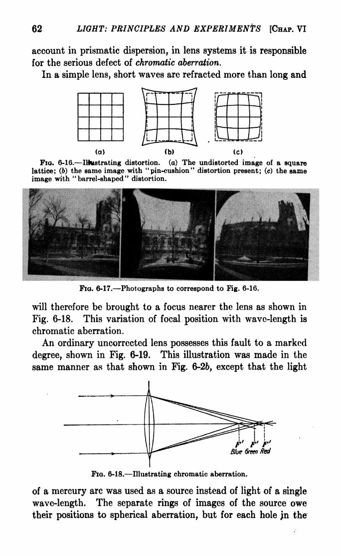
62 LIGHT: PRINCIPLES AND EXPERIMENTS [HAP. VI
account in prismatic dispersion, in lens systems it is responsible
for the serious defect of chromatic aberration.
In a simple lens, short waves are refracted more than long and
(a) (b) (c)
Fio. 6-16. Illustrating distortion, (a) The undistorted image of a squarelattice; (6) the same image with "pin-cushion" distortion present; (c) the sameimage with "barrel-shaped" distortion.
Fio. 6-17. Photographs to correspond to Fig. 6-16.
will therefore be brought to a focus nearer the lens as shown in
Fig. 6-18. This variation of focal position with wave-length is
chromatic aberration.
An ordinary uncorrected lens possesses this fault to a marked
degree, shown in Fig. 6-19. This illustration was made in the
same manner as that shown in Fig. 6-26, except that the light
Fio. 6-18. Illustrating chromatic aberration.
of a mercury arc was used as a source instead of light of a single
wave-length. The separate rings of images of the source owe
their positions to spherical aberration, but for each hole jn the

SBC. 6-13J ABERRATIONS IN OPTICAL SYSTEMS , 63
screen, except the center one, a small spectrum is formed. There
is a small amount of dispersion in the central image, since the
hole at the center of the screen is not vanishingly small. Like-
wise, for each other hole, there is a small amount of spherical
aberration, which results in a blurring of the spectrum so that the
separate images of the mercury spectrum have a tendency to
overlap. For each hole in the ring nearest the center, however,the SDectrum is distinct.
FIG. 6-19. Showing both spherical and chromatic aberration of a single lens.
The screen shown in Fig. 6-2a was placed over the lens and the photographicplate placed at the Gaussian image point. Since the unfiltered mercury arc was
used, each out-of-focus image is a spectrum.
13. Cauchy's Dispersion Formula. The index of refraction
of a transparent substance may be represented with sufficient
accuracy for many purposes by Cauchy's formula
n - n + + + - -
, (6-16)\a2^4 * ^ "
in which no, B t C, etc., are constants depending on the substance.
For practical purposes it is sufficient to use only the first two
terms of the right-hand side of eq. 6-16.

64 LIGHT: PRINCIPLES AND EXPERIMENTS [CHAP. VI
14. The Fraunhofer Lines. Accurate knowledge of indices of
refraction of glass dates from the time of Fraunhojer, who wasthe first to measure the indices in terms of definite spectral
positions instead of colors. He utilized the positions of the
strong absorption lines in the solar spectrum, whose wave-lengthshe found to be constant. His designations of these lines byletters are still used in optics. Since the development of strong
laboratory sources of light, other reference lines have come into
use, to most of which small letters have been assigned. In the
following table a number of wave-lengths are given, including all
the principal Fraunhofer lines. The unit used is the angstrom,
equal to 10~ 8 cm.
The variation of index of refraction with wave-length is small
compared to the index itself. For ordinary glass it is never more
than 2 per cent for the visible spectrum, i.e., for the range of
wave-length represented in the table above, and it is frequently
less. In designating a particular kind of glass it is customary
among manufacturers to give as the principal means of identifica-
tion the index of refraction for the D-line of Fraunhofer, and to
add for working purposes the indices for several other lines, and
the dispersive power, defined in Sec. 6-16.
15. Two Kinds of Chromatism. By the term chromatic
aberration is usually meant the difference with color of image-
position distance from the lens. Even if a system is corrected

SEC. 6-16] ABERRATIONS IN OPTICAL SYSTEMS 65
for this defect, there might still be chromatism present, for,
especially i the lens is thick, the principal planes for different
colors will not necessarily coincide. The result will be a differ-
ence of focal length for different wave-lengths, giving rise to a
difference of magnification. This defect is known as chromatic
difference of magnification, and sometimes as lateral chromatism.
Difference of image position for different wave-lengths is knownas axial, or longitudinal, chromatic aberration.
16. Achromatizing of a Thin Lens. The focal length of a thin
lens is given by
= (n-
l)k, (6-17)
in which k is a constant for a given lens. By differentiation,
df i jan w- -
where the quantity co = dn/(n 1) is called the dispersive power.1
For a range of wave-length from the C- to the (7-lines, for instance,
it may be written
fl'Q ^C / r* t f\\w =lr-T
. (6-19)
It should be pointed out that the numerator in eq 6-19 is not
strictly an infinitesimal dn but a finite Aw. In other words, co
is not the dispersive power for a particular wave-length, but the
average dispersive power over a range of wave-length. The
use of the symbol, dn, is justified by the fact that the difference
of index over the visible spectrum is rarely more than about
2 per cent of the index itself.
For a lens made of twa_thin4eesin contact.
1 = I + I,
from which, by differentiation, is obtained
_/*
<0l . C02= + ,
f> J\ h
1 It is customary for glass makers to give the value of 1 /, sometimes
called the Abbe number v.

66 LIGHT: PRINCIPLES AND EXPERIMENTS [CHAP. VI
since eq. 6-18 applies to each component separately. If the
system is to be corrected for chromatic aberration, df/f* must be
zero, and therefore
= o.
J2(6-21)
Hence f\ and /2 must be of opposite sign, since for all transparent
substances <oi and W2 have the same sign.1
Equation 6-21 says
that achromatism is obtained by combining two thin lenses, one
convergent and one divergent, of different dispersive powers.
Their focal lengths may now be calculated.
From eqs. 6-20 and 6-21,
=O>2
and /,2= (6-22)
Using eqs. 6-19 to 6-22, it is possible to calculate the correction
over any desired range. First must be decided for what wave-
lengths equality of focal length is desired. It is also important
to notice that if the first lens is to be convergent and the com-
bination also convergent, by eq. 6-22, f\ < /2. Hence, by
eq. 6-21, <oi < o>2.
A common combination Is a convergent lens of crown glass,
and a divergent lens of flint glass, corrected for equality of focus
for the F- and C-lines. Representative glasses of this type have
the following indices :
To calculate the focal lengths of the two lenses so that the
focal length fD of the combination is 50 cm., we may proceed as
follows : From eq. 6-19,
,, nw - me 1.53162 - 1.52293 ftft1AWQf;^(crown) = ^_ 1 g-gggjj
- 0.0165395.
1.63265 - 1.61549co2 (flint)
= = 0.0276614.nZD - 1 0.62036
1 That is. in the Cauchv formula, the constant B is alwavs oositive.
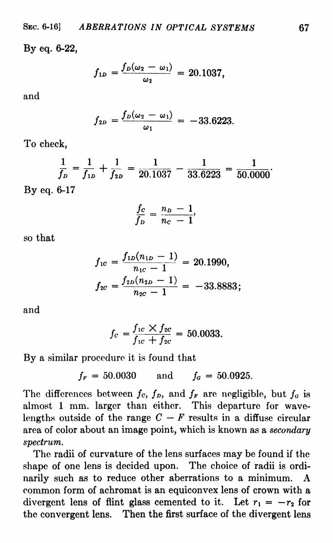
SEC. 6-16] ABERRATIONS IN OPTICAL SYSTEMS 67
By eq. 6-22,
fa = 'J^ m = 20.1037,CU2
and
To check,
I-JL-l-JLs: J 1 = 1
ID fio fa 20.1037 33.6223 50.0000*
By eq. 6-17
fc no 1
nc
so that
fie=
; j-
f _ J1D\n<lD x/ QQ QCOQ.J2C i d*5.5<5,
and
Jo-JIC "T /2C
By a similar procedure it is found that
ff = 50.0030 and f = 50.0925.
The differencevS between /c , fD ,and fF are negligible, but f is
almost 1 mm. larger than either. This departure for wave-
lengths outside of the range C F results in a diffuse circular
area of color about an image point, which is known as a secondary
spectrum.
The radii of curvature of the lens surfaces may be found if the
shape of one lens is decided upon. The choice of radii is ordi-
narily such as to reduce other aberrations to a minimum. Acommon form of achromat is an equiconvex lens of crown with a
divergent lens of flint glass cemented to it. Let n = r2 for
the convergent lens. Then the first surface of the divergent lens

68 LIGHT: PRINCIPLES AND EXPERIMENTS [CHAP. VI
will have the same radius as r2 . Using the index for the D-line
and applying eq. 6-17 in turn for each of the lenses, we obtain
n = 22.1061, rz = -22.1061,r, = -22.1061, r, = -369.402.
It is important to point out that the achromatism thus obtained
is an equality of focal length only, unless the lenses are very thin;
also that combining two lenses of different indices does not
accurately achromatize the combination for more than two wave-
lengths. In order to make a system achromatic or nearly so for
any appreciable region of the spectrum it is necessary to use more
than two elements. For the lens to be achromatic with respect
to image position, each element must be separately achromatized.
This is because the focal planes are not the same for different
a
FIG. 6-20.
wave-lengths. In Fig. 6-20 the lateral magnification of the first
lens is y\/y = a'/a, that of the second is y'/yi =b'/b, and that
of the whole system is y'/y =b'a'/ba. In order that the system
may be achromatized with respect to image position, there mustbe no difference of the distance b' for different wave-lengths, or
A6' =0, (6-230),
and for constancy of lateral magnification for different wave-
lengths,
(6-236)
Since a is constant, the condition in eq. 6-236 may be written
A(6'a'/6)= 0. But 6 -f- a' is constant for all wave-lengths,
hence
Aa' = -A6. (6-24)
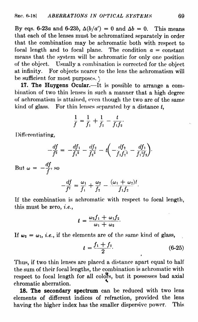
SBC. 6-18] ABERRATIONS IN OPTICAL SYSTEMS 69
By eqs. 6-23a and 6-236, A(6/a') = and A6 = 0. This meansthat each of the lenses must be achromatized separately in order
that the combination may be achromatic both with respect to
focal length and to focal plane. The condition a = constant
means that the system will be achromatic for only one position
of the object. Usually a combination is corrected for the objectat infinity. For objects nearer to the lens the achromatism will
be sufficient for most purposes. )
17. The Huygens Ocular. It is possible to arrange a com-bination of two thin lenses in such a manner that a high degreeof achromatism is attained, even though the two are of the samekind of glass. For thin lenses separated by a distance t,
1 _ 1 1 t
7" i Tf fl f* /!/
Differentiating,
/2
/I2
/22
V /I/'/2
But co = TJ so
df _ 0>i,
C02 (CO) + CO->)/~ " '
If the combination is achromatic with respect to focal length,
this must be zero, i.e.,
. _ t02/l + tO 1/2
COi + C02
If 2= wi, i>e., if the elements are of the same kind of glass,
t = ^4^2- (6-25)
^J
Thus, if two thin lenses are placed a distance apart equal to half
the sum of their focal lengths, the combination is achromatic with
respect to focal length for all colors, but it possesses bad axial
chromatic aberration.
18. The secondary spectrum can be reduced with two lens
elements of different indices of refraction, provided the lens
having the higher index has the smaller dispersive power. This

70 LIGHT: PRINCIPLES AND EXPERIMENTS [CHAP. VI
is true of glasses developed at the Jena Glass Works. With
these glasses it is also possible to correct for chromatic aberration
and curvature of the field at the same time. The Petzval con-
dition for no curvature of the field may be written
=0,
while eq. 6-21 may be written
/i2 +/2Wi = 0;
eliminating /i and /2 ,the result is
This result holds, it must be remembered, only for lens systems
which are so thin that no variation of the position of the principal
planes with color exists. Actually, very good achromats which
are not ideally thin can be made. A system which is aplanatic
and achromatic for two or more colors, and is free from secondary
spectrum is called apochromatic.
It is clear that there can be no such thing as perfect image
formation such as is postulated by the theory of ideal optical
systems. Some of the aberrations cannot be entirely eliminated,
and it is possible only to reduce them to a degree consistent with
the purpose for which the system is intended. The practical
lens maker accomplishes this by tracing representative rays
through the system.1
Problems
1. The radii of curvature of both faces of a thin convergent lens are
the same length. Show that for an object placed a distance from the
lens equal to twice its focal length the longitudinal spherical aberration
is given by
2/(n-
1)2'*
2. A spherical wave from a near-by source is refracted at a plane
surface of glass. What will be the character of the wave front after
refraction? Will it be free from aberrations?
3. Find the lengths and positions of the astigmatic line images formed
by a concave mirror whose diameter is 10 cm. and whose radius of
1 For an exposition of these methods the student is referred to Hardy and
Perrin, "The Principles of Optics," McGraw-Hill.

ABERRATIONS IN OPTICAL SYSTEMS 71
curvature is 50 cm. if the source is a point 75 cm. from the axis on a
plane 125 cm. from the vertex of the mirror. Find also the astigmaticdifference.
4. Using Young's construction, show the path of a ray refracted at a
convex lens surface of radius +r, (n'<n).5. Locate the conjugate aplanatic points of a spherical glass refracting
surface of radius +5, if the index is 1.57.
6. Calculate the constants of the doublet described in Sec. 6-16, if it
is achromatized for the C- and (r-lines, instead of for the C- and F-lines.

CHAPTER VII
OPTICAL INSTRUMENTS
1. The Simple Microscope. The Magnifier. If an objectis held somewhat closer to a thin positive lens than its principalfocal point and viewed through the lens, an enlarged, erect,
virtual image will be seen. Used in this way, the lens is a simple
magnifier. Its magnification is the ratio of the size of the imageformed on the retina with the aid of the lens to its size when viewed
by the unaided eye at normal reading distance. If this distance
is called N, and the virtual image formed by the magnifier is
considered to be N cm. away from the eye, then by eq. 2-7 the
lateral magnification is
R _ tf _ N + EV-r--
rBut E, the distance between the emergent focal point F f
of the
magnifier and the eye, is usually very small compared to TV and
may be neglected. Also, it is customary to consider N to be
about 25 cm., so that the magnification of a simple magnifier
may be written
25/3=
-y-(/in centimeters). (7-1)
Here/ is used instead of/', since for a lens in air they are the same.
It is best to avoid eyestrain by placing the object at the principal
focus F of the lens (see Fig. 7-1) so that the virtual image is at
infinity. This does not invalidate eq. 7-1, as a good working
rule, since the angle subtended by the virtual image at infinity
is not much different from that at normal reading distance, andthe virtual image is about the same size. This may be quicklyverified by experiment. To obtain the largest field, the eyeshould be close to the lens. A simple magnifier may be corrected
in the usual manner for chromatic aberration.
2. Compound Magnifiers* Because large magnification causes
great increase of the aberrations, simple magnifiers are usually72
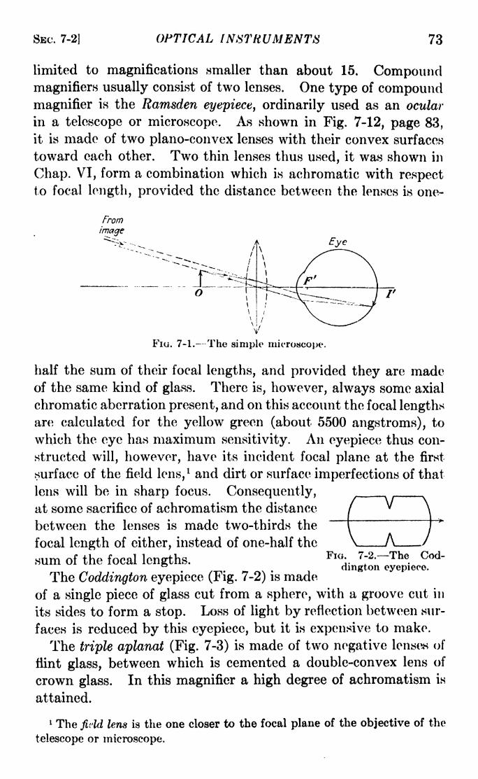
SEC. 7-2] OPTICAL INSTRUMENTS 73
limited to magnifications smaller than about 15. Compoundmagnifiers usually consist of two lenses. One type of compoundmagnifier is the Ramsden eyepiece, ordinarily used as an ocular
in a telescope or microscope. As shown in Fig. 7-12, page 83,
it is made of two plano-convex lenses with their convex surfaces
toward each other. Two thin lenses thus used, it was shown in
Chap. VI, form a combination which is achromatic with respectto focal length, provided the distance between the lenses is one-
From
image
o
FIG. 7-1. The simple microscope.
half the sum of their focal lengths, and provided they are madeof the same kind of glass. There is, however, always some axial
chromatic aberration present, and on this account the focal lengthsare calculated for the yellow green (about 5500 angstroms), to
which the eye has maximum sensitivity. An eyepiece thus con-
structed will, however, have its incident focal plane at the first
surface of the field lens,x and dirt or surface imperfections of that
lens will be in sharp focus. Consequently,at some sacrifice of achromatism the distance
between the lenses is made two-thirds the
focal length of either, instead of one-half the
sum of the focal lengths.Fl0
:.7;2--The
.
dmgton eyepiece.The Coddington eyepiece (Fig. 7-2) is made
of a single piece of glass cut from a sphere, with a groove cut in
its sides to form a stop. Loss of light by reflection between sur-
faces is reduced by this eyepiece, but it is expensive to make.
The triple aplanat (Fig. 7-3) is made of two negative lenses of
flint glass, between which is cemented a double-convex lens of
crown glass. In this magnifier a high degree of achromatism is
attained.
1 The field lens is the one closer to the focal plane of the objective of the
telescope or microscope.

74 LIGHT: PRINCIPLES AND EXPERIMENTS [CHAP. VII
There are several other types of magnifiers, most of which are
constructed for special purposes. One of these is a single block
of glass with a spherical top and with a flat or slightly concave
base to be placed in contact with the object.
3. The Gauss Eyepiece. For laboratory telescopes, espe-
cially those used with spectrometers, the Gauss eyepiece is
very convenient. Its construction is shown in Fig.
7-4. It is the same as the Ramsden eyepiece,~~"
except that between the two elements a thin plane
plate of glass is placed at an angle of 45 deg. with
FIG. 7-3- The the axis. Light admitted through an opening inrip e ap ana . ^e g^ Qf j. ne fafe is reflectcd down the axis of the
telescope, illuminating the cross hairs in its path. When the
telescope is focused for parallel light and has its axis perpendic-
ular to 'a plane reflecting surface placed before the objective,
images of the cross hair will be at the principal focus of the
objective. When these images coincide exactly with the cross
hairs themselves, the axis of the telescope is exactly perpendicu-
Source
Cross-hairs
U
JDraw fube-
f
FIG. 7-4. The Gauss eyepiece and draw tube.
lar to the reflecting surface. The focusing of the telescope for
parallel light may also be made more exact by eliminating all
difference of sharpness between the cross hairs and their images.l
4. The Micrometer Eyepiece. When small distances are to
be measured, a convenient instrument is the micrometer eyepiece.
This can be constructed in several forms, one of which is illus-
trated in Fig. 7-5. At the focal plane of the eyepiece are a fixed
1 For instructions concerning the use of the Gauss eyepiece, see
Appendix IV.

SBC. 7-6] OPTICAL INSTRUMENTS 75
cross hair F, and a movable cross hair M . The latter may be
moved perpendicularly to the axis of the eyepiece by means of a
fine-pitched screw. The head H may be divided into appropriate
divisions, usually small fractions of a millimeter, although for
some purposes angular measure is more convenient. With a
head of sufficient diameter the divisions may represent very small
distances or fractions of a degree, and in addition a vernier maybe used. It is not practical, however, to make divisions smaller
than are justified by the accuracy of the micrometer screw.
Sometimes a small-toothed edge is provided in the focal planeso that whole turns of the micrometer head may be easily counted.
If the ocular is of the Huygcns type (see Sec. 7-12), the cross hairs
are placed at the focal plane of the eye lens, and for the toothed
edge may be substituted a scale finely ruled on glass.
Objective
- Image atr infinity
IG. 7-6. The compound microscope.
6. The Compound Microscope. The optical parts of a com-
pound microscope consist of an objective and an eyepiece or ocular.
The former serves to produce a much enlarged real image of the
object; the latter, to view this image with still further magnifica-

76 LIGHT: PRINCIPLES AND EXPERIMENTS [CHAP. VI I
tion, in comparison with a scale if measurements of the object
are to be made. A schematic diagram is shown in Fig. 7-6.
The magnification is the product of the magnifying powers of
the two elements. Frequently a microscope is equipped with a
variety of objectives and oculars for different magnifications.
6. Numerical Aperture. In the chapter on diffraction it will
be shown that the radius of the image of a point object, i.e., the
distance from the center of the image to the first minimum of t ho
diffraction pattern, is given by
r = , (7-2)
where is the angle of diffraction, i.e., the angle subtended at the
lens by r. By convention, the limit of resolution of an optical
instrument is said to be reached when the center of the image of
one object just coincides with the first dark minimum of the
diffraction pattern of a second object. Hence images of two
point objects can just be resolved when their distance apart is r.
In the microscope, on account of the greater magnification,
the angle is large. Moreover, the object points seen with a
microscope are not self-luminous, and hence in themselves pro-
duce diffraction images of the source. Abbe has shown that in
consequence the smallest distance between two points in the
object which can be resolved is given by X/2n sin a, where n is
the index of refraction of the medium between the object and the
objective, and a is the angle between the axis and the limiting
rays which pass through the entrance pupil of the microscope.
The quantity n sin a was called by Abbe the numerical aperture
(N.A.) of a microscope. It is obvious that the limitation thus
set on the magnifying power is not due to aberrations but to the
effects of diffraction. From eq. 7-2 it follows that the size of the
central bright maximum of the diffraction pattern of a point
object is proportional to the wave-length of the light used. For
this reason, sometimes ultraviolet light is used to obtain higher
resolving power.The oil-immersion microscope
1is one in which the numerical
aperture and hence the resolving power is increased by the use of
an oil, usually oil of cedarwood, between the object and the
objective. Loss of light by reflection is thereby also eliminated.
1 See Sec. 6-9.

SEC. 7-8J OPTICAL INSTRUMENTS 77
7. Condensers. If the object is viewed with transmitted
light, it is frequently desirable to obtain greater illumination by* "^ans of a condenser. Sometimes this is merely a concave
mirror, which can be adjusted to reflect a convergent beam of
light from a nearby source into the objective. For short-focus
objectives more powerful condensers are used. They become in
fact integral parts of the optical system, and are often corrected
for aberrations so as to improve their light-gathering power.The larger the numerical aper-
ture, the more important does
the efficiency of the condenser
become.
8. Vertical and Dark-field
Illuminators. When veryshort-focus objectives are used
to view opaque objects which
must be illuminated from
above, it is difficult to illumi-
nate the object by ordinary
means. To overcome this diffi-
culty, a vertical illuminator may be used. This may consist of a
prism or mirror which reflects to the object a beam of light
admitted into the tube from the side, as shown in Fig. 7-7.
For observing small particles in colloidal suspensions, or fine
rulings on surfaces, it is desirable to use a dark-field illuminator.
In this type the light is incident upon the object at angles such
that it does not pass by transmission or ordinary specular1
reflection directly into the objective. Small particles or lines,
however, serve to diffract the light, and it is by means of the
pencil of diffracted light from each particle that the presence
of the particle is observed. One means of effecting this is bymeans of condensers such as are illustrated in Fig. 7-8. The
condenser contains an opaque centered disk which allows only a
ring of light to pass obliquely through a point in the object
just below the center of the objective. With dark-field illumina-
tion, particles as small as 5 X 10~7 cm. in diameter, or about
of the wave-length of light, may be observed.
<cO (b)
Fi. 7-7. Vertical illuminators.
1
Specular reflection is ordinary reflection from a polished surface, diffuse
reflection from a matt surface.
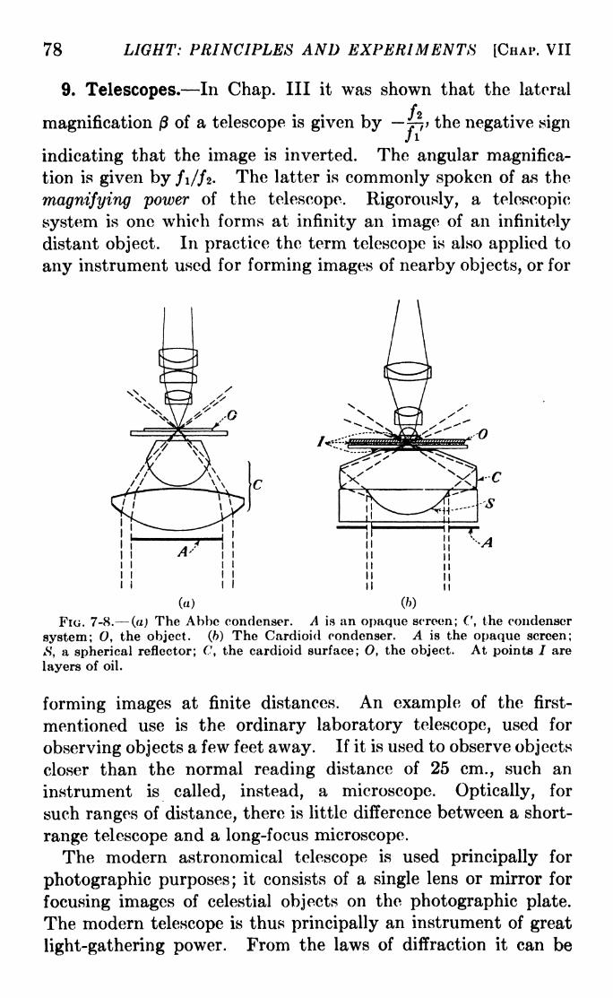
78 LIGHT: PRINCIPLES AND EXPERIMENTS [CHAP. VII
9. Telescopes. In Chap. Ill it was shown that the lateral
magnification of a telescope is given by ft; the negative sign
indicating that the image is inverted. The angular magnifica-
tion is given by fi/fz- The latter is commonly spoken of as the
magnifying power of the telescope. Rigorously, a telescopic
system is one which forms at infinity an image of an infinitely
distant object. In practice the term telescope is also applied to
any instrument used for forming images of nearby objects, or for
Av -'-4
(a)
FIG. 7-8. (a) The Abbe condenser. A is an opaque screen; (', the condenser
system; O, the object, (b) The Cardioid condenser. A is the opaque screen;
*S', a spherical reflector; C, the cardioid surface; O, the object. At points / are
layers of oil.
forming images at finite distances. An example of the first-
mentioned use is the ordinary laboratory telescope, used for
observing objects a few feet away. If it is used to observe objects
closer than the normal reading distance of 25 cm., such an
instrument is called, instead, a microscope. Optically, for
such ranges of distance, there is little difference between a short-
range telescope and a long-focus microscope.
The modern astronomical telescope is used principally for
photographic purposes; it consists of a single lens or mirror for
focusing images of celestial objects on the photographic plate.
The modern telescope is thus principally an instrument of great
light-gathering power. From the laws of diffraction it can be

SEC. 7-10] OPTICAL INSTRUMENTS 79
shown that the resolving power of a telescope is determined by the
size of the objective. To take full advantage of this, however,in visual use, it is necessary that the objective be the aperture
stop of the system. It is then the entrance pupil. In a visual
astronomical telescope in which both objective and ocular are
positive systems, a measure of the magnifying power may be
made by comparing the diameter of the objective with that of the
exit pupil, since the ratio of these two dimensions is equal to
/i//2- To find the size of the exit pupil, the telescope may be
pointed to the sky and a ground glass or paper screen used to
locate the position where the beam emerging from the eyepiece is
smallest. The well-defined disk of light at this point is the exit
pupil.
In order that the maximum field may be viewed, the entrance
pupil of the eye should be made to coincide with the exit pupil of
the telescope. In the Galilean telescope, the exit pupil is virtual,
and the field of view is in consequence restricted. This form
has, however, the advantage of shorter overall length, since the
eyepiece is a negative lens placed closer to the objective than
its principal focal point.
10. The Reflecting Telescope. Large modern astronomical
telescopes which are used principally for photographic observa-
tions are of the reflecting type. The mirror is a parabolized
surface, usually of glass coated with metal of high reflecting
power. Silver, chemically deposited, was until recently the
metal used. The disadvantage of silver is that it tarnishes
readily and loses its reflecting power. With recent improvementin technique it is now possible to deposit aluminum by evapora-tion in a high vacuum on even the largest mirrors. The oxide
formed on the aluminum on exposure to the air is an extremely
thin coat of transparent substance preserving the metal from
tarnish. Sometimes combinations of two metals prove more
satisfactory than aluminum alone, as, fir instance, a base coat
of chromium with a top coat of aluminum. Indeed, the tech-
nique of evaporation of metals for the production of reflecting
surfaces is so new that probably great improvements will be madein the future. In addition to its value in the visible spectrumbecause of superior reflecting power and durability, aluminum
has proved of great service in extending astronomical spectro-
scopic observations into the ultraviolet. Silver is almost trans-
80 LIGHT: PRINCIPLES AND EXPERIMENTS [CHAP. VIJ
parent in the region of 3300 angstroms, a fact which previouslylimited the ultraviolet spectroscopy of stellar objects.The image formed with a paraboloidal mirror is free from
spherical aberration on the axis and from chromatic aberration
over the entire field. For this reason, it is possible to make thefocal length shorter with relation to the aperture than in a
refracting telescope. The new telescope of the McDonaldobservatory has a diameter of 82 in. and a focal length of 26 ft.,
or a relative aperture of //3.8, resulting in a reduction of photo-graphic exposure time. In this way, the range of the instrumentfor faint celestial objects is effectively increased.
In the neighborhood of the axis, the field of a paraboloidal
reflecting telescope suffers from coma, a defect in which each
image is elongated as shown in Fig. 6-9. The length of the
comatic image, i.e., its dimension measured along a radius fromthe center of the field, is given approximately by L = 3/>2
0/16F2
,
where D/F is the relative aperture and 6 is the angular distanceof the star image in seconds of arc from the center of the field.
The breadth of the comatic image is approximately two-thirds of
the length. While the defect of coma thus increases in propor-tion to 0, the astigmatism is proportional to 2
,so that for tho
region close to the axis the elimination of coma is more important.In actual practice, differences of temperature in a turbulent-
atmosphere cause a blurring or "boiling," so that even stellar
images at the axis are enlarged and irregular. For this reasonthe distance from the axis at which coma becomes noticeable
depends upon the definition, or "seeing," as it is called. For
correcting this defect of coma the telescopes which have been
developed may be classified in three groups.a. In the first group may be placed those which achieve their
purpose to some extent by the addition of other mirror surfaces,which may or may not be modified from a spherical shape.While the original two-surface reflecting telescope proposed byGregory (Fig. 7-9a) and the Cassegrain form (Fig. 7-96) fall
in this group, the greatest advance was made by Schwarzschild
who, in 1905, designed a two-mirror telescope of the Gregoriantype in which each surface was modified in shape so that comaand spherical aberration were reduced to a minimum in the
neighborhood of the axis. It had a relative aperture of 1/3.5.Since in this instrument the field is flat and the residual astigma-

SBC. 7- JO] OPTICAL INSTRUMENTS 81
tism is balanced so that the primary and secondary foci coincide
at short distances from the axis, it fulfills the conditions for the
anastigmat described in Sec. 6-6, and can be called the Schwarzs-
child anastigmat.
b. In a second group may be placed those telescopes in which
the coma of a paraboloidal mirror is corrected by the use of a
specially designed lens placed between the mirror and its principal
focus. The disadvantage of correcting lenses of this type is that
in many cases they reduce the relative aperture by increasing the
focal length.
Oregorian
Newtonian
(c)
Fio. 7-9. -Early types of reflecting telescopes.
Professor Frank E. Ross of the Yerkes Observatory has
designed a "zero-power" lens combination 1
placed between the
mirror and its focal point, which makes no essential change
in the position of the principal focal plane of the telescope mirror,
but corrects for coma over a considerable area. It makes no
reduction in relative aperture, and actually increases the photo-
graphic speed of the telescope since the comatic images are
decreased in size.
c. A third type of correcting device is a single plate which has
surfaces so shaped that it modifies the character of the bundle
of rays from a point source before it reaches the reflecting mirror.
A most successful corrector of this type designed by B. Schmidt
1 Astrophysical Journal, 81, 156, 1935.

82 LIGHT: PRINCIPLES AND EXPERIMENTS [CHAP. VII
is illustrated in Fig. 7-10. The reflector is made spherical instead
of paraboloidal, so that coma is absent. At its center of curva-
ture is placed a disk of glass, one of whose surfaces is plane and
the other shaped so that the light refracted by it is made slightly
divergent by an amount necessary to eliminate spherical aberra-
tion. With a telescope of this type in which the mirror has a
diameter of 71 cm. and a focal length of 1 m. good star imageshave been obtained over a field 12 degrees in diameter.
FIG. 7-10. (a) An ordinary spherical reflector; (6) the Schmidt reflecting
telescope. The curvature of the upper surface of the compensating plate is
exaggerated./
11. Oculars (Eyepieces). In the section on magnifiers it was
pointed out that a Ramsden eyepiece makes an excellent reading
glass or magnifier. --In fact the only difference between magni-fiers and oculars is that while the former are used to view real
objects, the latter are used to view images formed by another
part of an optical system. Any magnifier will serve as an
eyepiece for a telescope or microscope, but most of them not so
well as an eyepiece specially constructed for the purpose. The
triple aplanat in particular makes an excellent eyepiece.
12. The Huygens Eyepiece. The two principal types of
oculars are the Huygens and the Ramsden. ^ The Huygens,sometimes called a negative ocular, is illustrated in Fig. 7-11. It is
made of two elements of the same kind of glass separated by a

SEC. 7-13] OPTICAL INSTRUMENTS 83
distance equal to one-half the sum of their focal lengths. The
field lens A is placed just inside the focus F of the objective,
this focus serving for the field lens as a virtual object of which an
erect image I is formed closer to A. The eye lens B is so placedthat / is at its focal point, thus forming an image at infinity.
The ratio of the focal length of the field lens to that of the eyelens is about 2:1 if the eyepiece is to be used for a microscope and
somewhat larger for a\^telescope. Sometimes a scale or cross
/ F
-The Huygens eyepiece.
hairs, or both, are placed at /, but if the eye lens is uncorrected
for aberrations, the scale cannot be very long. Because the
distance between the elements is (/i /2)/2, the Huygens ocular
is free from chromatic aberration with respect to focal length,
although the longitudinal aberration and curvature of the field
are considerable. These may be corrected by special means,such as changing the curvature of the surfaces of the field lens
Field Field Eye Exit
stop lens lens pupil
FIG. 7-12. The Ramsden eyepiece.
while retaining its converging power, or achromatizing the
eye lens.
fer 13. ^The Ramsden Eyepiece. The essentials of construction
of the Ramsden eyepiece, shown in Fig. 7-12, have been described
in the section on magnifiers. This ocular has a flatter field than
the Huygens and possesses the added advantage that the focal
plane of the objective precedes the field lens, so that a scale or

84 LIGHT: PRINCIPLED AND EXPERIMENTS [CHAP. VII
traveling cross hair can be used more successfully. The Ramsdenalso has the added advantage that it may be focused very sharplyon the cross hairs or scale. This is important if eyestrain is to be
avoided. The observer should first relax the accommodation byresting the eye on a distant view; then, while looking in the eye-
piece, he should draw it away from the cross hairs until theyjust begin to appear diffuse. Two or three trials will quicklydetermine the correct focal position for the eyepiece.
14. Erecting the Image. Sometimes it is desirable to havean erect image instead of the inverted image seen in the ordinary
Erect virtual
image
(a)
Inverted -^T- ^
virtualimage"'
Fio. 7-13. (a) The Galilean refracting telescope; (6) the astronomical refractingtelescope.
eyepiece. In the prism binocular this is done by means of
prismatic reflections. The simple negative lens of the Galilean
telescope (Fig. 7-13a) also serves to erect the image. In terres-
trial telescopes, where it is desirable that a distant scene be
erected, a four-element eyepiece, illustrated in Fig. 7-14 is used.
15. The Spectrometer. Perhaps the most important optical
instrument for the study of light is the spectrometer. It may be
used to determine indices of refraction, to study the effects of
diffraction, interference, and polarization, and to make observa-
tions on spectra. For the last-named purpose it has reached its
greatest development in the spectrograph which is essentially a
spectrometer equipped with a camera in place of the eyepiece.

SBC. 7-15] OPTICAL INSTRUMENTS 85
The essential parts of a spectrometer are shown in Fig. 7-15.
At S is a slit, with accurately parallel jaws, which may be altered
in width from about 0.001 mm. to a few millimeters. The varia-
tion in width may be accomplished by a motion of one jaw
(unilateral), if only narrow slits are to be used, or of both jaws
equally (bilateral) in case wide apertures are desired, or sym-
FIG. 7-14. -The erecting eyepiece.
metry of widening is to be maintained. The slit is mounted at
one end of a tube, at the other end of which is the collimator
lens Li which for ordinary visual purposes must be a good crown-
flint achromat. The collimator tube is equipped with one or
more devices for altering its length. Usually this is accomplished
by a rack and pinion which can be turned to change the slit
distance from the lens. At L2 is a second lens, preferably an
FIG. 7-15. The spectrometer.
achromat identical with L\. This lens, the tube on which it is
mounted, and the eyepiece E constitute a telescope. At the
focal plane of the objective are mounted the cross hairs. The
distance of the cross hairs and eyepiece from the objective maybe changed by means of a rack and pinion. In some cases, the
lenses L\ and L2 are also independently mounted on drawtubes

86 LIGHT: PRINCIPLES AND EXPERIMENTS [CHAP. VII
which may be clamped to the main tubes at different distances.
The collimator and telescope tubes are mounted on arms which
have as an axis of rotation the central vertical axis of the spec-
trometer. With this axis as a center of rotation also are the
spectrometer table T on which prisms or other optical parts maybe mounted between the collimator and telescope, and a grad-uated circular scale. The circular scale should be as large as the
dimensions of the instrument will permit. It is divided into
units of angle, and may be graduated from to 180 deg. in two
equal sections or from to 90 deg. in each quadrant. It should
be read at opposite sides, either by means of verniers or bymicroscopes. In addition to being adjustable about the central
axis, the collimator and telescope are also adjustable about
vertical axes and horizontal axes perpendicular to their lengths.
When the instrument is in adjustment, the longitudinal axes of
the collimator and telescope should meet at the central vertical
axis of the spectrometer.Directions for the adjustment of a spectrometer will be found
in Appendix IV.
Problems
1. What is the magnifying power of a glass ball 1.5 cm. in diameter?
(n = 1.5)
2. A piece of capillary glass tubing has an outside diameter of 7 mm.The capillary appears to be about 1 mm. wide when looked at through
the glass wall. What is its real diameter? (n 1.5)
3. A magnifying glass whose focal length is 6 cm. is used to view an
object by a person whose smallest distance of distinct vision is 25 cm.
If he holds the glass close to the eye, what is the best position of the
object?
4. The objective of a telescope has a diameter of 30 mm. and a focal
length of 20 cm. When focused on a distant object, it is found that the
diameter of the exit pupil is 2.5 mm. What is the magnifying powerof the system? If the eyepiece is a single thin lens what is its focal
length?
6. A celestial telescope has a focal length of 25 ft. What must be the
focal length of an eyepiece which will give a magnification of 300
diameters?
6. The objective of a telescope has a focal length of 40 cm. and the
ocular has a focal length of 5 cm. Plot the magnification as a function
of object distance, if the latter varies from 5 m. to infinity.

OPTICAL INSTRUMENTS 87
7. The objective of a field glass has a focal length of 24 cm. Whenit is used to view an object 2 m. away the magnification is 3.5. Whatis the focal length of the ocular? What will be the magnification for an
object a great distance away?8. A large astronomical telescope usually has a "finder
11 attached
to it, which consists of a short-focus telescope fastened to the cylinder
of the larger one. Explain the use of the finder.

CHAPTER VIII
THE PRISM AND PRISM INSTRUMENTS
1. The Prism Spectrometer. Probably the most importantuse of the prism is for the spcctroscopic analysis of light. Becauseof the variation with wave-length of the index of glass and other
transparent substances, light passed through a prism is spreadout into a spectrum by means of which the analysis may be made.
FIG. 8-1.---A section through a prism perpendicular to the refracting edge.
In Fig. 8-1 is shown a section made by passing a plane through a
prism perpendicular to the two refracting surfaces and the
refracting edge of the prism, i.e., the edge in which the refracting
surfaces intersect. The plane of the paper is the plane of
incidence. A beam of) light incident on the first surface is bent
by refraction through an angle i r, and at the second surface
through an angle i' r',where i and i' are the angles made
between the directions of the beam in air and the normals to the?
surfaces. The total deviation is thus A = i + i' r r'.
From the geometry of the figure it is easily proved that A, the
refracting angle of the prism, is equal to r H- r', so that
A - i + i' - A. (8-1)
If the incident beam is fixed in direction, and the prism rotated
88
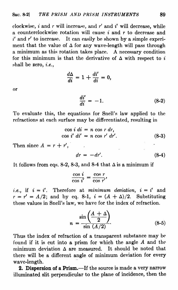
SEC. 8-2] THE PRISM AND PRISM INSTRUMENTS 89
clockwise, i and r will increase, and r' and i' will decrease, while
a counterclockwise rotation will cause i and r to decrease and
i' and r' to increase. It can easily be shown by a simple experi-
ment that the value of A for any wave-length will pass througha minimum as this rotation takes place. A necessary condition
for this minimum is that the derivative of A with respect to i
shall be zero, i.e.,
or
gr= -1. (8-2)
To evaluate this, the equations for Snell's law applied to the
refractions at each surface may be differentiated, resulting in
cos i di = n cos r dr,
cos i' di' n cos r' dr'. (8-3)
Then since A = r + r',
dr = dr'. (8-4)
It follows from eqs. 8-2, 8-3, and 8-4 that A is a minimum if
cos i _ cos r
cos if
cos r'
i.e., if i = i'. Therefore at minimum deviation, i = i' and
r = / = A/2; and by eq. 8-1, i = (A + A)/2. Substituting
these values in Snell's law, we have for the index of refraction.
'A + A'
n = .\A/' (8-5)sin (A/2)
Thus the index of refraction of a transparent substance may be
found if it is cut into a prism for which the angle A and the
minimum deviation A are measured. It should be noted that
there will be a different angle of minimum deviation for every
wave-length.2. Dispersion of a Prism. If the source is made a very narrow
illuminated slit perpendicular to the plane of incidence, then the

90 LIGHT: PRINCIPLES AND EXPERIMENTS [CHAP. VIII
dispersion resulting from the dependence of n upon X will result
in a spectrum in which each wave-length of the incident light will
be a line, i.e., an image of the slit,1 whose magnification depends
upon the focal lengths and the adjustment of the telescope and
collimator.
Dispersion can be defined as the rate of change of deviation
with wave-length. For a given prism angle A and a constant
angle i the deviation changes with index of refraction and with
i'. Thus the definition of dispersion just given becomes, from
eq. 8-1,
n dA _ di'v ~j\ ~j\"d\ d\
This expression is for the angular dispersion, and not for the
actual separation of the spectral lines at the focal plane of the
telescope objective. Its value cannot be obtained in a single
step since there is no simple expression connecting i' and X.
It is possible to find di'/dn from Snell's law and dn/d\ by differ-
entiation of the Cauchy dispersion function of eq. 6-16; these
multiplied together give the desired expression for di'/d\. This
derivation will now be made.
The Cauchy dispersion formula
n - Wo + r + ' ' '
is an empirical relation in which the values of no and B are experi-
mentally determined. It is not valid when the region of the
spectrum to be considered contains absorption bands, but it is
satisfactory for ordinary transparent substances such as glass,
quartz, fluorite, etc. By differentiation,
dn 2B ,Q ^3x
= ~v" (8
'7)
In order to obtain di'/dn we may proceed as follows: From
Snell's law, for the second surface,
cos irdi' = dn sin r' + n cos / dr
f
, (8-8)
1 If only a slit and prism are used, and the spectrum lines viewed with the
unaided eye, the optical system of the eye produces the images of the slit.

SEC. 8-2] fHE PRISM AND PRISM INSTRUMENTS 91
while for the first surface, since i is constant,
n cos r dr + dn sin r = 0.
Since dr dr', eq. 8-9 may be written
7 , dn sin rdr =
n cos r
which, substituted in eq. 8-8, gives
di' sin (r + /) sin A
(8-9)
dn cos i cos r cos z cos r
Multiplying eqs. 8-7 and 8-10 gives for the dispersion
di' -2B sin A
(8-10)
X3 cos i cos r
Thus the dispersion of a prism depends on four factors:
A
Pi
(8-11)
(1) the
FIG. 8-2.
character of the glass, given by the constant B, (2) the wave-
length X, (3) the refracting angle A of the prism, and (4) the
direction of the light through the prism as given by the angle r.
The value of i' will, of course, depend on r, A, and B, and also on i.
For the case of minimum deviation, eq. 8-11 may be simplified.
Consider a beam of light of width a, composed of parallel rays,
emerging from the prism. At minimum deviation (Fig. 8-2),
a = P'Q' cos i', R'Q' - P'Q' sin (A/2), whence
P'Q' = (QQ'- PP'}
2 sin (A/2)'

92 LIGHT: PRINCIPLES AND EXPERIMENTS [CHAP. VIII
If we call QQ' PP' the effective thickness t, then
t cos i'a
2 sin (A/2)
Putting the value of cos i' from this equation in eq. 8-11, modified
for the condition of minimum deviation, we obtain
dif 2Bt
The negative sign has been dropped since it merely indicates, as
shown by eq. 8-7, that as X increases, n decreases.
Each image of the slit, or spectrum line, is observed to be
curved. Rays from the upper and lower ends of the slit undergo
greater dispersion than those from the center, having a longer
path through the prism because they pass through at an angle
with the optical axis of the system, i.e., with the plane of Fig.
8-1. The greater the distance above or below the axis is the part
of the slit from which a ray comes, the greater is the dispersion,
thus accounting for the fact that all lines are curved, with their
ends pointing toward shorter wave-lengths.
It should be emphasized that the dispersion D given by eqs.
8-11 and 8-12 is the change of angle with wave-length. Some-times the term dispersion is used to mean the separation in
angstroms per millimeter in the field of the telescope or on the
photograph of the spectrum. Thus a spectrum is said to have a
dispersion of 10 angstroms per millimeter when two spectrumlines whose difference of wave-length is 10 angstroms are just
1 mm. apart. Obviously this quantity will depend not onlyon the angular dispersion D, but also on the focal length, i.e.,
on the magnification of the telescope or camera objective.
3. Resolving Power of a Prism. It is customary to define
the resolving power of a dispersive instrument as
R = 1
where d\ is the smallest wave-length difference which can be
detected at the wave-length X. It will be shown in the chapteron diffraction that limitation of the wave front from a narrow-
slit source by an aperture of width a results in an intensity
distribution in the image, shown in Fig. 12-17. Moreover, two
SEC. 8-3] THE PRISM AND PRISM INSTRUMENTS 93
such images are said to be just resolved when the middle of one
coincides with the first minimum of intensity of the other. 1 The
angular separation between the two images is then 6 = X/a.
In case the angular separation is that between two spectral lines,
= dif
. Hence for X in eq. 8-13 may be substituted a di', so
that the resolving power is
a di'
But by eq. 8-12 this is equal to a D, so that
(8-14)
provided the prism is set for minimum deviation.
Thus the resolving power of a prism at minimum deviation
depends on the character of the glass, the wave-length, and the
effective thickness of the prism. Since the effective thickness
depends on the refracting angle A and the aperture a, any increase
in either will result in an increase in the resolving power. Thelimit to the value of A for a single prism is imposed by the
necessity for keeping ;*' less than the critical angle of refraction.
Sometimes the light is passed through two or more prisms in
succession in order to obtain greater dispersion, but this involves
other optical problems which limit the usefulness of the method.
Further consideration of eqs. 8-12 and 8-14, both of which,it must be remembered, apply only in the case of minimum
deviation, is desirable to point out that while the width a of the
beam of light intercepted by the prism appears explicitly in the
expression for D, it does not appear in that for R. Nevertheless,while the resolving power depends on the aperture in the case of
the prism, the dispersion does not. This apparent paradox is
because, in eq. 8-12, t is always proportional to a; if a is decreased
in a certain ratio, the effective thickness t is reduced in the same
ratio, and the dispersion will be unchanged. On the other hand,if a is reduced, R will be reduced in proportion, since R is equalto a D.
The resolving power of a prism is not necessarily that of the
spectrometer on which it is mounted. If the aperture of the
system is limited by the sizes of the collimator and telescope,
1 See Fig. 12-19o.
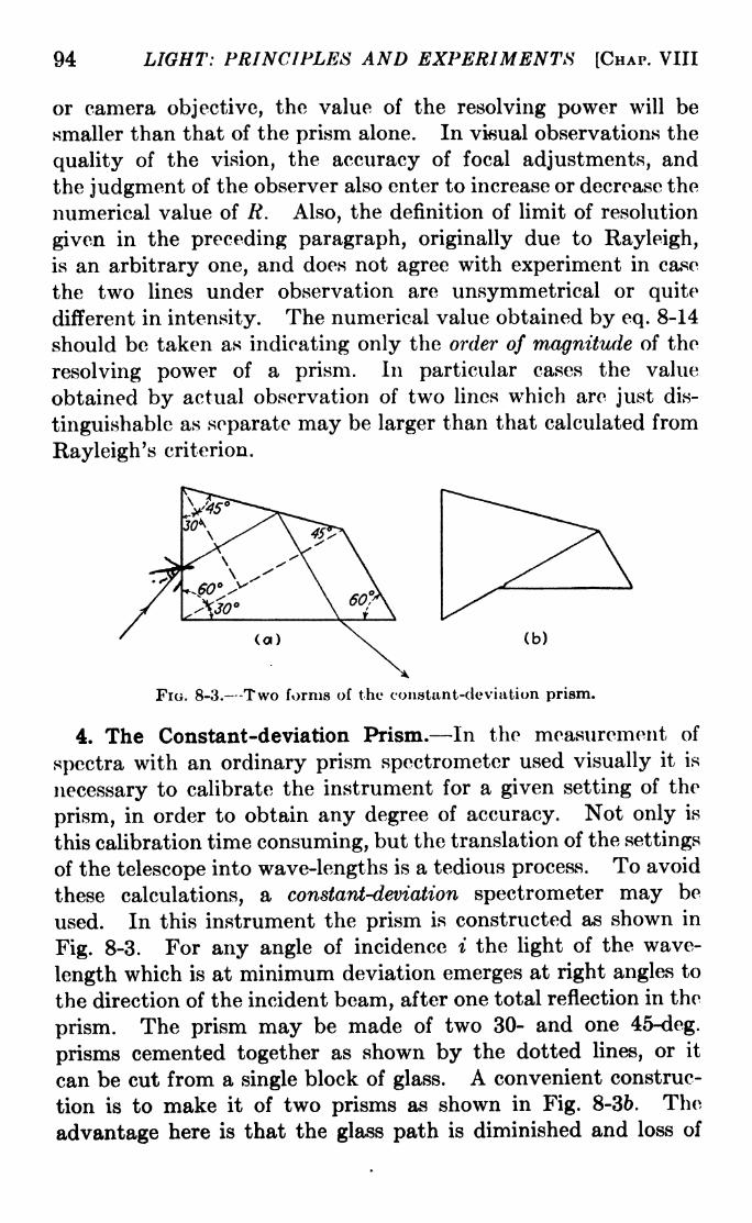
94 LIGHT: PRINCIPLES AND EXPERIMENTS [CHAP. VIII
or camera objective, the value of the resolving power will be
smaller than that of the prism alone. In visual observations the
quality of the vision, the accuracy of focal adjustments, and
the judgment of the observer also enter to increase or decrease the
numerical value of R. Also, the definition of limit of resolution
given in the preceding paragraph, originally due to Rayleigh,
is an arbitrary one, and does not agree with experiment in case
the two lines under observation are unsymmetrical or quite
different in intensity. The numerical value obtained by eq. 8-14
should be taken as indicating only the order of magnitude of the
resolving power of a prism. In particular cases the value
obtained by actual observation of two lines which are just dis-
tinguishable as separate may be larger than that calculated from
Rayleigh 's criterion.
(b)
FIG. 8-3. -Two forms of the constant-deviation prism.
4. The Constant-deviation Prism. In the measurement of
spectra with an ordinary prism spectrometer used visually it is
necessary to calibrate the instrument for a given setting of the
prism, in order to obtain any degree of accuracy. Not only is
this calibration time consuming, but the translation of the settings
of the telescope into wave-lengths is a tedious process. To avoid
these calculations, a constant-deviation spectrometer may be
used. In this instrument the prism is constructed as shown in
Fig. 8-3. For any angle of incidence i the light of the wave-
length which is at minimum deviation emerges at right angles to
the direction of the incident beam, after one total reflection in the
prism. The prism may be made of two 30- and one 45-deg.
prisms cemented together as shown by the dotted lines, or it
can be cut from a single block of glass. A convenient construc-
tion is to make it of two prisms as shown in Fig. 8-36. The
advantage here is that the glass path is diminished and loss of
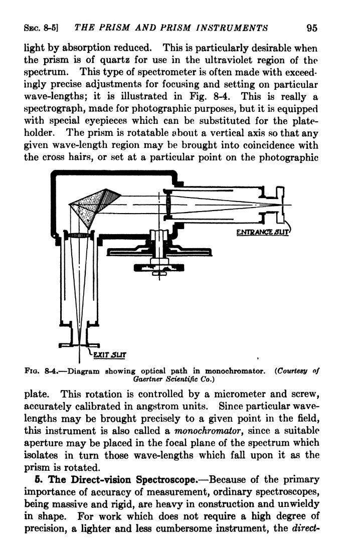
SBC. 8-5] THE PRISM AND PRISM INSTRUMENTS 95
light by absorption reduced. This is particularly desirable whenthe prism is of quartz for use in the ultraviolet region of the
spectrum. This type of spectrometer is often made with exceed-
ingly precise adjustments for focusing and setting on particular
wave-lengths; it is illustrated in Fig. 8-4. This is really a
spectrograph, made for photographic purposes, but it is equippedwith special eyepieces which can be substituted for the plate-
holder. The prism is rotatable about a vertical axis so that anygiven wave-length region may be brought into coincidence with
the cross hairs, or set at a particular point on the photographic
EJCIT5IJT
FIG. 8-4. Diagram showing optical path in monochromator. (Courtesy ofGaertner Scientific Co.)
plate. This rotation is controlled by a micrometer and screw,
accurately calibrated in angstrom units. Since particular wave-
lengths may be brought precisely to a given point in the field,
this instrument is also called a monochromator, since a suitable
aperture may be placed in the focal plane of the spectrum which
isolates in turn those wave-lengths which fall upon it as the
prism is rotated.
6. The Direct-vision Spectroscope. Because of the primary
importance of accuracy of measurement, ordinary spectroscopes,
being massive and rigid, are heavy in construction and unwieldyin shape. For work which does not require a high degree of
precision, a lighter and less cumbersome instrument, the direct-

)6 LIGHT: PRINCIPLED AND EXPERIMENTS [CHAP. VIII
vision spectroscope, is used. If two prisms, one of flint glass and,he other of crown are placed together as shown in Fig. 8-5, the
lifference of dispersion will result in a difference of deviation and;he production of a spectrum, for if the deviations of the two
jrisms are equal for one wave-length, they will not be HO for any)ther wave-length. To obtain sufficient dispersion it is custom-
iry to cement together three or five prisms, as illustrated in
ftg. 8-6. It is evident that the entire optical system is nearlyn a straight line. The composite prism is usually cemented,>r otherwise firmly fixed, in a tube provided with a slit at one end,
in appropriate collimator and telescope, and cross hairs or scale
or calibration. Since the whole instrument can be pointed
;asily at a source and used in a manner similar to a monocular, it
s extremely useful for rapid visual inspection of spectra. Some>f the more elaborate direct-vision spectroscopes may even be
ised for measurement of spectral-line positions with an accuracy)f about 1 angstrom.
FIG. 8-5. FIG. 8-6. The direct-vision prism system.
6. Critical Angle of Refraction. If the angle of incidence of a
Deam of light on a glass surface is increased until it approaches)0 deg., the angle of refraction will approach a limiting value
ivhich depends on the indices of refraction of the glass and of the
ur traversed by the incident beam. In the case of a glass plate
n air, the index of the air may be taken as unity, so that for
> = 90, the index of refraction of the glass is given by
n = _^L_, (8-15)sin rc
where rc is called the critical angle of refraction. For glass whose
index is 1.5, rc is approximately 41.8 deg. Consequently any
light incident from the glass side on the air-glass interface at an
angle greater than rc will be totally reflected, since there can be
none refracted. Total-reflection prisms so constructed as to take
advantage of this principle are often better than mirrors for
turning beams of light through right angles. The reflecting
power of most metal mirrors is far from unity and varies with

SBC. 8-7] THE PRISM AND PRISM INSTRUMENTS 97
the wave-length. The total-reflection prism is free from dis-
persion, since the angle of reflection is independent of the wave-
length. On the other hand, a glass prism absorbs some light,
and for regions of the spectrum not transmitted by ordinary
glass the prism must be made of quartz or fluorite. In some
cases rock salt or lithium fluoride prisms are used.
It is necessary that the reflecting surface of the prism be free
from dirt, oxidation, or other contamination, since the presenceof a film other than air will change the critical angle, and more
often than not cause light to be refracted out of the prism. Bymeans of prisms of special design, the light can be turned through
angles other than a right angle.1
FIG. 8-7. Critical angle of refraction. If the direction of the light is reversed, all
rays incident on AB at angles greater than that for ray a will be totally reflected.
7. Index of Refraction by Means of Total Reflection. The
phenomenon of total reflection of light provides a useful means
of determining the index of refraction of transparent substances.
If a prism is illuminated by a broad beam of convergent light
as shown in Fig. 8-7, the field at E will be divided into a dark
portion on one side of the ray a and a bright portion on the other.
If the refracting angle A of the prism is measured, and the angle
i' between the normal to the surface AC and the emergent ray a,
and these two values substituted in eq. 8-20, the index of the
prism may be calculated. It will then be possible to measure
the index of refraction of a liquid placed in contact with the
side AB.Let the index of refraction of this medium be n, and that of the
glass prism, na . Then Snell's law,
1 A fairly complete discussion of total-reflection prisms of a variety of
designs is found in Bureau of Standards Scientific Paper No. 550, 1927, by I. C.
Gardner.

98 LIGHT: PRINCIPLES AND EXPERIMENTS [CHAP. VIII
n sin i = ng sin r,
at grazing incidence becomes
^ = -4 (8-16)n sin r
At the surface AC the prism is in contact with air, and SnelFs
law for this case is
sin i' = n g sin r'. (8-17)
Also
A = r + r'. (8-18)
Eliminating r and r' from these three equations, we have
n = sin A\/na2 sin 2
i' sin i' cos .A. (8-19)
The measured values of A, i', and ng substituted in eq. 8-19 will
FIG. 8-8.
give the value of n, the desired index of refraction of the liquid.
The value of n,the index of refraction of the glass prism, may
be found with great precision for any wave-length by measuringthe angle A and the minimum deviation A, and substituting their
values in eq. 8-5. This method is to be preferred to the measure-
ment of ng by a measurement of i' for grazing incidence as sug-
gested above. If, however, the latter method is to be used,
eq. 8-19 may be put into a suitable form by putting n =1,
whereupon
[
^ ~1 2sin i + cos A
sin A J
SEC. 8-8] THE PRISM AND PRISM INSTRUMENTS 99
8. The Abbe Refractometer. This is an instrument designedto make use of the principles outlined in the two precedingsections for measuring the indices of refraction of liquids. While
many refinements are built into the best instruments, the essen-
tial optical part is a pair of right-angle prisms illustrated in
Fig. 8-8. When placed with their diagonal sides face to face
with a thin film of liquid between, the index of refraction of the
liquid may be found by measuring the angle i9
corresponding to
the light which enters the prism A and is refracted at the critical
angle. Substituting of this value, and the measured values
of A and ng in eq. 8-19, yields the value of the index of refraction
of the liquid. *
Problems
1. Show that the constants of the Cauchy dispersion formula are
given by
/&1A1J W 2X 2
2
A =^1 2~^~X7~
'
J5 = r - c-~
AI AI>
in which HI and n 2 are the indices of refraction at two wave-lengths Xi
and X 2 .
2. What will be the dispersion of a 60-deg. prism made of glass No. 3
in Table 2 at the end of this volume, at 7000 angstroms? At 4000
angstroms? Give the units in each case. If the prism face is com-
pletely filled with light, how wide must it be if the sodium doublet
5890 and 5896 angstroms is to be just resolved?
3. What factors actually enter into an experimental determina-
tion of resolving power other than those considered in the preceding
problem?4. A prism for a spectrograph is to be made out of glass whose index
UD is 1.72. What is the maximum prism angle which can be used?
5. The critical angle of refraction of a substance is 58 deg. What is
its index of refraction?
6. Show that if the angle of a glass prism is larger than twice the
critical angle of refraction, no light can be passed through it by refraction.

CHAPTER IX
THE NATURE OF LIGHT
1. Light as a Wave Motion. Speculations, theories, and
investigations concerning the nature of light have had a promi-nent place in man's intellectual endeavors since the beginning of
history. There havejboeh short periods of time when groups,sometimes including practically all students of natural philosophy,have been convinced that-the nature of light was understood.
On the whole, however, during most of the time, diverse opinionshave been held, based on conflicting theories and speculations or
on apparently conflicting experimental evidence. It is not
within the province of an intermediate course in optics to present
the history, or the arguments concerning different theories, of
the nature of light, or, more generally, of radiation. But just
as in the introduction to geometrical optics the concept of the ray
was adopted because it enabled us to continue expeditiously our
development of the subject of image formation, so in physical
optics we can adopt the concept of light as a wave motion propa-
gated from a source in all directions through space. Moreover,we can make use of the wave theory only as long as it is not in
conflict with observations, whether these be in the limited field
of the topic under discussion or in some other part of the larger
field of physical phenomena.The quantum theory introduces a concept of light which is
more complex than a mere wave motion. According to this
view, when light is emitted or absorbed, the energy of the 1
light appears in the form of concentrated units, called photon^.1
These photons are supposed to move in straight lines, when in
free space, with the speed of light, and to have an energy which
is related in a simple manner to the frequency of the associated
1 It is perhaps worthwhile to warn the student against the indiscriminate
use of the words "photon
" and "quantum.1 ' A photon consists of a certain
amount or quantum of energy,*? but not all quanta are photons.100
*

SBC. 9-l| THE NATURE OF LIGHT 101
light wave. In problems of the transmission of light, where no
interchange of energy between radiation and matter isinvolved,
the quantum theory, like the classical wave theory, describes the
propagation of the light in terms of a wave motion. It is prob-lems of this kind, including mainly refraction, diffraction, inter-
ference, and polarization, with which we shall be concerned in the
next few chapters. For these purposes, therefore, the assump-tion of light waves is entirely adequate, and it is not necessarythat we concern ourselves with the complementary assumptionof the existence of photons. On the other hand, the origin of
spectra, the interaction of light with material media throughwhich it passes, and certain phenomena classified under the
headings of magneto- and electro-optics cannot be satisfactorily
explained by the classical wave theory of radiation. For these,
the quantum theory signalized by the names of Planck, Ein-
stein, Bohr, and others offers a satisfactory explanation. This
early quantum theory, however, in turn fails to encompass all
the intricacy of detail in modern observations in the field of light.
To take its place has arisen what is known as quantum mechanics.
While this later quantum theory goes far in unifying the classical
and earlier quantum concepts, we have not lived long enoughwith it to reduce it to simple terms. Accordingly, for an ele-
mentary presentation, it is necessary to rely upon classical or
quantum theories in turn to "explain" those phenomena to
which they are individually best fitted. This process is, however,not entirely without a satisfactory basis, for, it will be noted, in
order to deal with either the origin of the radiant energy (as
photons) in atoms or molecules, as in spectra, or its interaction
with material media, as in the photoelectric effect, the quantumtheory is more suitable, while the classical wave theory is quitesufficient to explain those light phenomena which deal only with
the passage of the light through space. In diffraction, where we are
accustomed to thinking of a material obstacle as taking part in
what happens, it is entirely immaterial of what elements the
obstacle is made; the important detail is that a part of the
"front" of the light propagated through space is obstructed andcannot pass on to the place where the image is formed. Even in
polarization, where the nature of the medium assuredly enters
into the entire problem, we can describe the characteristics of the
transmitted light adequately by means of the classical theory.
102 LIGHT: PRINCIPLES AND EXPERIMENTS [CHAP. IX
Experimental evidence supports the hypothesis that light is
a wave motion, transverse in character, propagated through
space with a finite velocity. The theory of light as a transverse
wave motion has gone through several phases. In the earliest
of these, it was felt absolutely necessary to suppose space to
consist of an elastic-solid medium of great rarity, patterned in its
characteristics after those substances which were known to be
the medium of transfer of other disturbances such as sound and
water waves. This elastic-solid medium could, therefore, be
considered to consist of particles obeying the same laws as ordi-
nary matter, but in such a way that suitable density and elasticity
could be assigned to the medium. Later, this hypothetical
medium was abandoned in favor of the more abstract idea of an
all-pervading "luminiferous ether," different from the elastic-
solid medium in that it possessed no such definite"particle''
characteristics, but retaining the properties of elasticity and
density so necessary for the representation of the wave motion
which traverses it. With Maxwell's introduction of the elec-
tromagnetic theory of light, this elastic medium was replaced byone with the electrical characteristics of a dielectric constant
and a magnetic permeability. On this view the wave has an
electric field and a magnetic field, each transverse to the direc-
tion of propagation and perpendicular to the other. This elec-
tromagnetic theory of light waves has now completely superseded
the idea of waves in an elastic ether. The ether, if we continue
to use the term, is now thought of as a region with certain elec-
trical characteristics rather than as an elastic solid. In this sense
the idea of transverse waves in the ether is in accord with the
latest developments of relativity and quantum theory.
2. Velocity, Frequency, and Wave-length. The velocity of
light in free space is the same for all wave-lengths. This con-
clusion is supported by a variety of observation. A wave dis-
turbance propagated through space with a velocity c and a
frequency n will have a wave-length X. These three quantities
are related by the equation
c = nX. (9-1)
The value of c is approximately 3 X 10 10 cm. sec." 1;hence for a
wave-length X = 5 X 10~6cm., the frequency n will be 0.6 X 10 15
sec." 1. If the time it takes a point on the wave train to pass

SEC. 9-3] THE NATURE OF LIGHT 103
through a complete cycle of phases is called the period T, then
n = 1/T, and
_ XC ~
T'(9-2)
3. Simple Harmonic Motion. It has been pointed out in
Sec. 9-1 that our concept of the nature of a light disturbance has
passed beyond the stage at which it was considered to be an
oscillatory displacement of material particles. The form of
analytical expression, however, need not be changed. At a point
in space, the disturbance due to the passage of a train of light
waves may be a simple or a complex wave motion. Also, it can
be shown that a complex oscillatory motion may be represented
FIG. 9-1. Illustrating simple harmonic motion.
as a summation of a number of simple harmonic motions. Wemay therefore arrive at equations describing wave motions bythe development of the summation of a number of simple har-
monic disturbances of a material particle.
The equation for a simple harmonic motion may be obtained
by considering the motion executed by a point P moving with
uniform angular speed in a fixed circle. The projection of this
motion upon a diameter of the circle is a simple harmonic motion.
We may thus consider the motion of a particle S in a straight line
(Fig. 9-la) to be a simple harmonic motion, provided the dis-
placement of S is always given by
s = a sin w<,
in which a is the maximum displacement, i.e., the radius of the
circle, co is the angular velocity of the point P, and t is the time
which has elapsed since the particle left the point in its upward
journey. If T is the time taken for one complete cycle, then

104 LIGHT: PRINCIPLES AND EXPERIMENTS [CHAP. IX
w = 27T/77
, and the displacement will be
s a sin 2*7=- (9-3)
In Fig. 9-16 the displacement is plotted as a function of the time,
the solid curve being the graph of eq. 9-3. In general, however,it is desirable to express the displacement in terms of the time
which has elapsed since the beginning of the motion, i.e., since the
particle was at some other point such as S'. In eq. 9-3, however,it is assumed that the particle is at the position of zero displacer
ment at the beginning of the time t. In general this will not be
true. To represent the most general case, therefore, we must
consider that the particle is at some position S' when t = 0;
the displacement s is, as before, the distance from to S, and
instead of eq. 9-3, we have
s = a sin (POP' - BOP") = a sin I 2r -<p I (9-4)
If the point S' should be above the middle point 0, as S", the
value of <p is positive. The dotted curve in Fig. 9-16 is the graphof eq. 9-4.
4. Phase and Phase Angle. The phase of a simple harmonic
motion refers to the particular stage of the cycle of motion being
executed. Two particles executing simple harmonic motions
parallel to AA' in Fig. 9-la are in the same phase if they are at
the positions of zero displacement at the same time and are also
moving in the same direction; if moving in opposite directiorife
they are in opposite phase. It is not necessary, however, that
the simple harmonic motions be executed in parallel lines nor
that they be of the same amplitude. They must be going throughthe same part of their cyclical motion at the same time, so that
the equations for the displacements are the same functions (sines
or cosines) of the same angles. The motions represented by eqs.
9-3 and 9-4 are not in the same phase, the difference of phase
angle between them being <p. On the other hand, the motions
given by
x = a sin(34
-)'
y = 6 sin (2^ -<f),

SEC. 9-5] THE NATURE OF LIGHT 105
are in the same phase, even though they are along x- and y-direc-
tions perpendicular to each other, and have different maximumamplitudes.
Obviously the phase angle corresponding to the displacement
passes through all values from to 2ir in succession, repeating this
change as long as the motion continues. It follows that the
phase angle in eq. 9-4 is given by
5. Composition of Simple Harmonic Motions. There are twocases to be considered: The composition of (1) simple harmonic
(a) (b)
FIG. 9-2. (a) Graphical method of composition of two simple harmonicmotions. (6) The solid line gives the resultant of two simple harmonicmotions which are shown by the dotted lines.
motions in the same direction, and (2) simple harmonic motions
at right angles. All cases come under these two heads, since
two or more motions at an angle not nor 90 deg. can be sepa-
rately resolved into components at right angles, which maythereupon be composed. There are two general methods, the
graphical and the analytical, for effecting this composition.
The graphical method will be discussed first.
Graphical Methods. The composition of two simple harmonic
motions of the same period T, executed in the same direction,
but not necessarily of the same amplitude, may be represented as
in Fig. 9-2a. The displacements Si and s2 differ in phase angle
by P2OPi. The total displacement OS along AA' is given by the
projection of the resultant radius OR, which is the diagonal of the

106 LIGHT: PRINCIPLES AND EXPERIMENTS [CHAP. IX
parallelogram formed by the radii OP\ and OP2 . Also,
OS = OS i + OSz- The individual simple harmonic motions
and their resultant are plotted in
Fig. 9-25.
While this method may be applied
successively to as many componentsas desired, a much easier method is to
make use of the vector polygon, illus-
trated in Fig. 9-3. The lengths of the
vectors are the amplitudes of the
separate components; the angles a\ t
2 , etc., are the phase angles; OR is
the amplitude of the resultant, andFIG. 9-3. Vector addition of ^
simple harmonic motions in its phase angle is ROB. This method,8ame line '
which may be extended to give the
summation of any number of components, is extremely useful in
the solution of problems in diffraction and will be made use of in
Chap. XII.
FIG. 9-4. Composition of two simple harmonic motions at right angles.
If the two component vibrations are at right angles, they maybe compounded graphically as illustrated in Fig. 9-4. The
basis of the method is to make use of a series of equidistant points
on circles drawn concentrically, with their radii equal to the
maximum amplitudes of the two disturbances. These points are
numbered so that the zero point in each case corresponds to the
displacement for which t = 0. The values of the simultaneous

SEC. 9-5] THE NATURE OF LIGHT 107
displacements corresponding to the number k may be called
xk and yk, respectively. In order to get the displacement due to
the composition of the two disturbances at any instant i, it is
necessary to find on this coordinate diagram the position of the
point (xi,yi). The resultant disturbance will be the curve
plotted through a series of points thus found.
Analytical Methods. As in the case of graphical methods there
are two general cases to be considered: (a) when the vibrations
take place in the same direction, (b) when at right angles. Thefirst of these is important in diffraction and interference, which
are dealt with in the chapters immediately following this. Since
the only problem of vibrations at right angles with which wehave to deal is in the case of double refraction in crystals, case
(6) will not be discussed here. The special case referred to will
be found in the treatment of elliptically polarized light, Sec.
13-11.
For case (a) consider two simple harmonic motions executed
in the same direction with the same period T. They may be
represented by
(9-5)
The difference in phase between them is given by <p\
Expanding each sine term in eq. 9-5, and adding,
s = Si -h 2= ai(sin 6 cos <pi cos sin <
4- 2(sin 6 cos v>2 cos 6 sin v>2), (9-6)
in which for convenience the symbol has been substituted for
2irt/T. At this point it is convenient to choose an angle 8 such
that
A cos 5 = ai cos <p\ + a 2 cos,
,q-,
A sin 6 = ai sin ^i + a sin
If the first of eqs. 9-7 is multiplied by sin 6 and the second bycos 9, and the second subtracted from the first,
A (cos 5 sin sin 6 cos 6) a\ sin cos <pi -f a2 sin 6 cos <p
ai cos 6 sin <f>\a2 cos 6 sin

108 LIGHT: PRINCIPLES AND EXPERIMENTS [CHAP. IX
in which the right-hand side is the same as the right-hand side of
eq. 9-6. Hence,
s = s\ -f 2= Al sin 2ir-=j cos 5 cos 2?r~ sin 8
J
= A sin \2irt- A (9-8)
Also, if eqs. 9-7 are squared and added, the result is
cos (<p*-
>i). (9-9)
It is evident that A is the resultant amplitude of the compositionof the two simple harmonic motions, for if <?2 <f>\ is zero or any
integral multiple of 2ir, the disturbances are in the same phaseand A 2 =
(a\ + a2)2
;while if w <pi is equal to (2n l)/2
times 2rr, where n is a whole number, the disturbances are in the
opposite phase, and A 2(a\ a2)
2. In this case, the amplitude
will be zero provided a t= a2 .
6. Characteristics of a Wave Motion. Although, as has been
pointed out in Sec. 9-1, light waves are no longer thought of as
disturbances in an elastic-solid medium, in order to develop
the equation of a wave motion adequate for present purposes,
we may consider the form of the wave to depend upon the motion
transmitted to the particles of such a medium. A particle
moving with a harmonic motion of the kind described in the
previous sections will act as the source of a wave train. Let O
(Fig. 9-5) be a source communicating its harmonic motion to a
medium having an elasticity E and a density d. The velocity
of propagation of the wave is e = \/E/d. The displacement at
a given instant along the line OS is given by s = a sin 2trt/T,
and the displacement at the same instant of a particle from a
(t t'\point X a distance x from is given by 6 = a sin 2r( -~,
~~~f)'
where t' is the time it takes the wave to travel from to X. In
other words, the difference of phase between the motions at
and X is given by t'IT. But since the time taken by the wave
to travel from to X is t' = x/c, and since c = \/T, t'/T = x/\.
Hence the displacement at X is given by
W' *}H*~x|
a sin ZrU; - r (9-10)

SBC. 9-7] THE NATURE OF LIGHT 109
Although eq. 9-4 bears a superficial resemblance to eq. 9-10,
it is not the same. The former gives the displacement at anytime t of a single vibrating particle; the latter gives at any one
FIG. 9-5. Illustrating the characteristics of a simple wave motion.
instant an instantaneous "snapshot" of the displacements of all
the particles along the path of the wave.
The difference of phase between the motions at and X is
x/\'} if this quantity is a whole number, the motions at the two
points are in the same phase. Two particles at points X\ andX2 will execute motions whose difference of phase is given by the
difference of their phase angles
(9-11)
DistanceFio. 9-6. Superposition of two wave trains traveling in the same direction
7. The Principle of Superposition. If light from two sources
passes through a small opening at the same time, two separate
images will be formed, each of which will in no way be affected
by the presence or absence of the other. This will be true,
unless the sources are so close together that their images overlap,
even though at the opening the wave trains pass through the
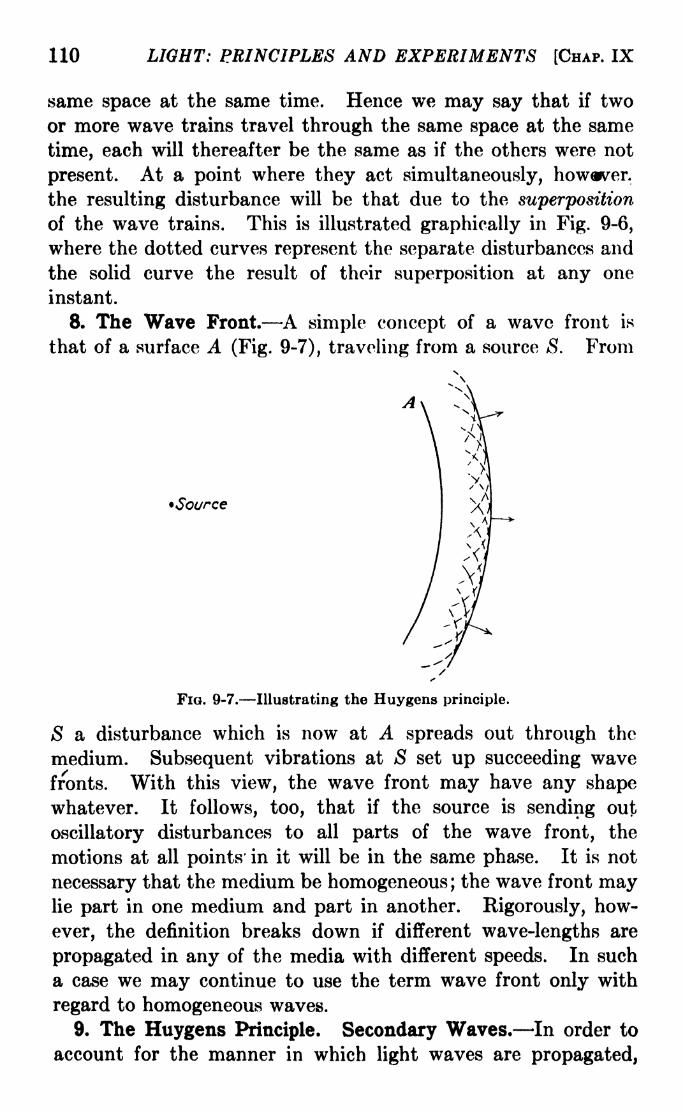
110 LIGHT: PRINCIPLES AND EXPERIMENTS [CHAP. IX
same space at the same time. Hence we may say that if two
or more wave trains travel through the same space at the same
time, each will thereafter be the same as if the others were not
present. At a point where they act simultaneously, howwver,
the resulting disturbance will be that due to the superposition
of the wave trains. This is illustrated graphically in Fig. 9-6,
where the dotted curves represent the separate disturbances and
the solid curve the result of their superposition at any one
instant.
8. The Wave Front. A simple concept of a wave front is
that of a surface A (Fig. 9-7), traveling from a source S. From
Source
FIG. 9-7. Illustrating the Huygens principle.
S a disturbance which is now at A spreads out through the
medium. Subsequent vibrations at S set up succeeding wave
fronts. With this view, the wave front may have any shapewhatever. It follows, too, that if the source is sending out
oscillatory disturbances to all parts of the wave front, the
motions at all points in it will be in the same phase. It is not
necessary that the medium be homogeneous ;the wave front may
lie part in one medium and part in another. Rigorously, how-
ever, the definition breaks down if different wave-lengths are
propagated in any of the media with different speeds. In such
a case we may continue to use the term wave front only with
regard to homogeneous waves.
9. The Huygens Principle. Secondary Waves. In order to
account for the manner in which light waves are propagated,
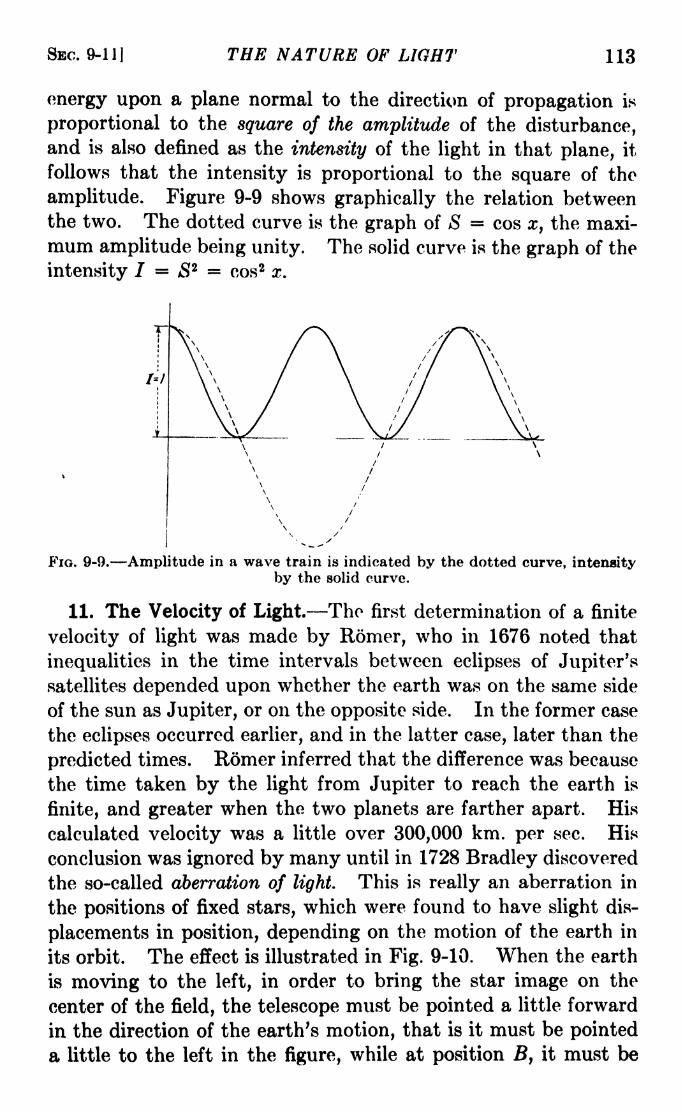
SBC. 9-11] THE NATURE OF LIGHT 113
energy upon a plane normal to the direction of propagation is
proportional to the square of the amplitude of the disturbance,and is also defined as the intensity of the light in that plane, it
follows that the intensity is proportional to the square of the
amplitude. Figure 9-9 shows graphically the relation betweenthe two. The dotted curve is the graph of S = cos x, the maxi-
mum amplitude being unity. The solid curve is the graph of the
intensity / = S2 cos2 x.
FIG. 9-9. Amplitude in a wave train is indicated by the dotted curve, intensityby the solid curve.
11. The Velocity of Light. The first determination of a finite
velocity of light was made by Romer, who in 1676 noted that
inequalities in the time intervals between eclipses of Jupiter's
satellites depended upon whether the earth was on the same side
of the sun as Jupiter, or on the opposite side. In the former case
the eclipses occurred earlier, and in the latter case, later than the
predicted times. Romer inferred that the difference was because
the time taken by the light from Jupiter to reach the earth is
finite, and greater when the two planets are farther apart. His
calculated velocity was a little over 300,000 km. per sec. His
conclusion was ignored by many until in 1728 Bradley discovered
the so-called aberration of light. This is really an aberration in
the positions of fixed stars, which were found to have slight dis-
placements in position, depending on the motion of the earth in
its orbit. The effect is illustrated in Fig. 9-10. When the earth
is moving to the left, in order to bring the star image on the
center of the field, the telescope must be pointed a little forward
in the direction of the earth's motion, that is it must be pointed
a little to the left in the figure, while at position B, it must be

114 LIGHT: PRINCIPLES AND EXPERIMENTS [CHAP. IX
pointed a little to the right. The angle of aberration a. is about20.5 sec. of arc. Bradley concluded that this alteration of the
apparent direction of the light was due to the relative velocities,
c of the light and v of the earth. The relation between these
velocities and a is given by tan a =v/c. This gives a value of a
little less than 300,000 km. per sec. for c.
In 1849, Fizeau made a preliminary experimental determina-
tion of the velocity of light, using the toothed-wheel method,illustrated schematically in Fig. 9-11. A simple illustration will
Earth'sorbit
v \
FIG. 9-10. Illustrating how the angle of aberration arises. During the time
the light traverses the length of the telescope, the latter moves from the position
indicated by the dotted outline to that given by the solid outline.
suffice to show the manner in which this device may be used to
measure c. Suppose the light beam passes through a slot on
the rim, is reflected from the distant mirror, and returns on the
same path just as the next slot is exactly in position to receive it.
Then the ratio of the velocity of the wheel's rim to the velocity
of light is the same as the ratio of the distance between the two
slots to the distance traveled by the light, which is 2TM in the
figure.
In the year following Fizeau's experiment, the rotating-mirror
method was used by Foucault. This method is shown schematic-
ally in Fig. 9-12. Light from the source S is reflected from the
rotating mirror R to a distant mirror M. The center of curvature

SEC. 9-11] THE NATURE OF LIGHT 115
of M is at R so that with a stationary mirror R the light will
be reflected directly back on its path, to S. Actually it returns
to /Si, having been reflected by mirror Af2 . If R is turning at
high speed, in the time during which the light passes from R to
M and back, the mirror has turned through a small angle, so that
FIG. 9-11. Fizcau'e toothed-wheel apparatus. T is the toothed wheel; Licollimates the beam of light; Li at the distant station focuses the light upon themirror M; the source is at <S; and the eyepiece or telescope at E.
the return beam, instead of arriving at Si, is observed at Si, a
small distance from Si. From a measurement of S\Si, the
angle through which R has turned may be calculated. If also
the angular velocity of R and the distance 2RM are known, the
velocity of light may be found.
FIG. 9-12. Foucault's rotating-mirror apparatus.
The actual experimental technique and calculations involved
in both Fizeau's and Foucault's experiments are far more than
the bare details just given, and the reader is referred to more
extended treatises for their complete description.1
1See, for instance, Preston, "Theory of Light," 4th ed., Macmillan.
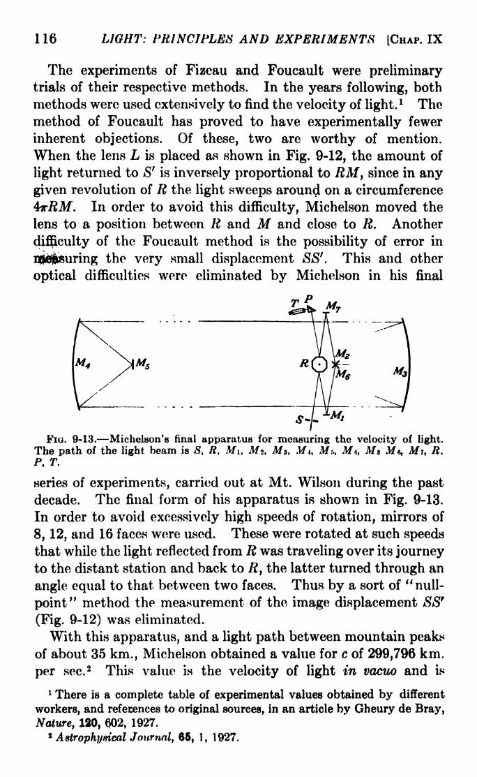
1 16 LIGHT: PRINCIPLES AND EXPERIMENTS (CHAP. IX
The experiments of Fizeau and Foucault were preliminarytrials of their respective methods. In the years following, both
methods were used extensively to find the velocity of light.l The
method of Foucault has proved to have experimentally fewer
inherent objections. Of these, two are worthy of mention.
When the lens L is placed as shown in Fig. 9-12, the amount of
light returned to S' is inversely proportional to RM, since in any
given revolution of R the light sweeps around on a circumference
4irRM . In order to avoid this difficulty, Michelson moved the
lens to a position between R and M and close to R. Another
difficulty of the Foucault method is the possibility of error in
i|jfi|wuring the very small displacement SS'. This and other
optical difficulties were eliminated by Michelson in his final
FIG. 9-13. Michelson's final apparatus for measuring the velocity of light.
The path of the light beam is S, R, Mi, M, Ms, M*, M:,, M\, Ms M , Mi, R,P, T.
series of experiments, carried out at Mt. Wilson during the past
decade. The final form of his apparatus is shown in Fig. 9-13.
In order to avoid excessively high speeds of rotation, mirrors of
8, 12, and 16 faces were used. These were rotated at such speeds
that while the light reflected from R was traveling over its journeyto the distant station and back to R, the latter turned through an
angle equal to that between two faces. Thus by a sort of "null-
point" method the measurement of the image displacement SSf
(Fig. 9-12) was eliminated.
With this apparatus, and a light path between mountain peaksof about 35 km., Michelson obtained a value for c of 299,796 km.
per sec. 2 This value is the velocity of light in vacuo and is
1 There is a complete table of experimental values obtained by different
workers, and references to original sources, in an article by Gheury de Bray,
Nature, 120, 602, 1927.*Astrophysical Journal, 85, 1, 1927.

SBC. 9-12] THE NATURE OF LIGHT 117
obtained by adding to the observed velocity a correction for the
index of refraction of the atmosphere. In a later experiment,carried to conclusion after his death in 1931, the light path wasenclosed in an evacuated tube 1 mile long. By means of multiple
reflections, the actual path was made eight to ten times as great.
A rotating mirror with 32 faces was used. The mean value of
many determinations was 299,774 km. per sec.1
These later determinations of c by Michelson and his associates
were made with such a degree of precision that there was remark-
able consistency between the individual observations of which
the published values are the mean. Conservatively estimated,this consistency was between 50 and 500 times as great as in
previous experimental determinations.
The velocity of light has also been obtained by using the Kencell (effect of electrical birefringence) as a shutter to cut off the
light beam. By this method, which is discussed in Sec. 16-10,
the value of c is found to be 299,778 km. per soc.'
^12. Wave Velocity and Group Velocity. Rayleigh was the
first to point out that the velocity of light measured in a refracting
medium is not the velocity of the individual waves. Instead,
because of the difference of velocity with wave-length, the
measured value will be that of a periodicity impressed upon the
wave train. The velocity of this periodicity is called the group
velocity. Consider a wave train having two wave-lengths, as
illustrated in Fig. 9-14a, in which the dotted line represents the
longer wave-length, traveling faster than the shorter. While at
the instant represented the two are in phase at point A, giving
rise to a group amplitude shown in Fig. 9-146, somewhat later
the amplitude will build up a little to the left of the point A.
In other words, the group will have a slightly smaller velocity
than that of the individual waves. The energy belongs to the
group rather than to the waves, and the observed velocity will be
that of the group.The effect may be illustrated by the manner in which waves
travel over the surface of water. It will be noticed that the
1 MICHELSON, PEASE, and PEARSON, Astrophysical Journal, 82, 935, 1935.
This series of experiments indicated also a monthly variation over a range of
about 20 km. per sec., but the spread of the observations was sufficiently
great to render its reality questionable. Whether this is real or is due to
some instrumental effect is not at present known.
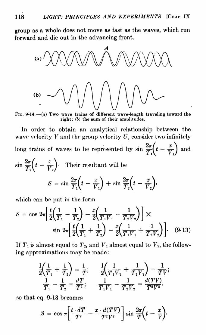
118 LIGHT: PRINCIPLES AND EXPERIMENTS [CHAP. IX
group as a whole does not move as fast as the waves, which run
forward and die out in the advancing front.
(b)
FIG. 9-14. (a) Two wave trains of different wave-length traveling toward the
right; (6) the sum of their amplitudes.
In order to obtain an analytical relationship between the
wave velocity V and the group velocity U, consider two infinitely
r/ x \long trains of waves to be represented by sin 7=-! t =-
)
^i\ KI/
2ir/ x \[ t 77- )
Their resultant will be\ K 2/
and
sn
a . 2iri. x \ . . 2irf. xs = sm
F,V~YJ
+ smF,V
~ Ywhich can be put in the form
S = cos3r[i(l
-1)
-l(f v i
-,^-J J
X
sn (9-13)
If Ti is almost equal to T>2) and V\ almost equal to 72 ,the follow-
ing approximations may be made:
J_T2
so that eq. 9-13 becomes
e f*'^S = cos TT-
f^. 2*1
sin -=rl

SBC. 9-12] THE NATURE OF LIGHT 119
This is an equation in which the cosine part is a periodically
varying amplitude factor, representing a wave group whichmoves with a velocity V equal to the ratio of dT/Tz to
d(TV)/T2Vz,so that, using the relationship V = \/T, we obtain
V*dT Vd\ - XrfF XdF~d(TV)
In an experimental determination of the velocity of light in
carbon bisulphide, Michelson found that the ratio of the velocityin air to that in carbon bisulphide was 1.76. The ratio of the
indices of refraction, however, gave a value of 1.64. The differ-
ence is because the index of refraction is expressed as the ratio of
the wave velocities, while, as pointed out above, the measured
velocity is that of the group. By applying the correction termin eq. 9-14 the figures were found to agree.
Problems
1. Plot the graph of the simple harmonic motion given by
s = 5 cos-p
2. Using the parallelogram method, draw the graph of
Si = ai sinf
2wjr and s 2= #2 sin
V^TT^T +
representing two displacements along the same axis, for a\ =5, a 2
=(3,
T! = 2T 2 , <p= 7T/4.
3. Draw a graph of the resultant motion of displacements
x = a sin ( 27r 0i ),
y = b sin
where a =7, 6 = 10, 0i = ?r/6, 6 2
= T/2.

CHAPTER X
INTERFERENCE OF LIGHT
1. Interference and Diffraction Compared. In Sec. 9-9 it
was shown that two Huygens wavelets will unite to produce light,
provided the difference of path from their starting^jjoint. to the
point wherejjhey combine is equal to an even number of half
wave-lengtfis ;and that they will unite to produce darkness if the
difference of path is an odd number of half wave-lengths. Simi-
larly it was shown that the effect of restricting t.hfi lighten a
portion of the wave front by a narrow slit will produce an inten-
srty~paElerh in Which the distribution of energy depends on the
wave-length of the light and the width of the slit. All such
patterns which similarly depend on the limitation of the wave front
are called diffraction patterns. They may be shown to owe their
appearance to the fact "that "in directions other than that of the
incident wave there is not complete mutual cancellation of the
light. A phenomenon bearing a superficial resemblance to that
of diffraction is obtained if the beams of light from two separate
parts of the wave front are made to reunite under conditions which
will be described. The result is called interference of light. It is
similar to diffraction in the sense that there exist alternate light
and dark regions, depending on whether the two wave trains
cancel each other, wholly or in part, or whether they reinforce
each other. It is different from diffraction, however, since it does
not necessarily depend upon any restriction of the wave front.
Instead, the best interference patterns are produced with wave-
fronts so extended that no diffraction phenomena of ordinary
magnitudes exist.
'2. Conditions for Interference. There are certain experi-
mental conditions which must be fulfilled for the production of
observable interference. These are:
a. The light in the two wave fronts which combine to give interference
must originally come from the same source.
b. The difference of optical path between the beams must be very
small, unless the light is monochromatic or nearly so.
120

SBC. 10-2] INTERFERENCE OF LIGHT 121
c. The wave fronts, on recombining to form interference patterns,
must be at a small angle to each other.
There is a fourth condition concerning the state of polarization
of the light, which may be left to the chapter dealing with that
subject.
The first condition is made necessary by the nature of light
itself. According to spectral theory, radiation of a particular
frequency occurs when an atom or molecule undergoes a transi-
tion from a given energy state to one of smaller energy. Such
FIG. 10-1.
transitions occupy a time of the order of 10~8sec., during which a
photon, or quantum, of radiant energy, passes out into space.
The chance is believed to be extremely small that the same or
another atom or molecule in another part of the source will emit
a train of waves of any duration capable of producing interfer-
ence with that from the first.
The second condition may be illustrated by the diagrammatic
representation in Fig. 10*1 of two interfering trains of white light.
These are originally from the same source, but by some sort of
apparatus the original wave train has been divided into two
at a very small angle, advancing toward the right. The differ-
ence of optical path from the source to the position A is zero,

122 LIGHT: PRINCIPLES AND EXPERIMENTS [CHAP. X
and there the two waves, indicated by solid curves, will be in the
same phase and will also reinforce each other throughout their
paths. Since the difference of path from the source is zero, the
reinforcement will take place for all wave-lengths. At a position
B, where the difference of path is X/2, the two wave trains indi-
cated by solid curves Are opposite in phase and will cancel each
other, provided they are of the same amplitude, while some other
pair of wave trains of different wave-length X7
,indicated by the
dotted curves, will not be opposite in phase and will to some
degree reinforce each other. At a position C, as at A, there is
again reinforcement for wave trains of wave-length X, and can-
cellation for those of wave-length X7
. Thus, for white light, onlya few fringes are seen on either side of the middle position A.
Outside of the region where fringes are seen, although at each
point destructive interference exists for some wave-length, partial
or complete reinforcement exists for all others. This results in
a complete masking of all interference except for the few fringes
already mentioned. Except for the middle one, these will be
colored, with the dispersion increasing with increasing distance
from the middle.
If the source is one which contains only a few strong mono-
chromatic 'radiations, interference fringes will appear with fair
visibility over a considerable range on either side of the middle
position. The mercury arc and the neon discharge tube are
examples of this type of source.
If there are only two wave-lengths, the fringes will have maxi-
mum visibility at the point of zero difference of path, and also
at the points where the path difference is an integral number of
times one wave-length and also an integral number of times the
other. At points in between, reinforcement will take place for
one wave-length and partial or complete cancellation for the
other, with the result that the visibility of the fringes will be
low or zero. 1 There will be a more extended treatment of this
1 The appearance or nonappearance of the fringes depends also upon the
difference of color, i.e., upon the sensitivity of the eye for the two colors.
If one wave-length is in the yellow, to which the eye is most sensitive, and
the other in the deep blue, the fringes due to the yellow will be seen even if
the intrinsic intensity of the blue is equal to that of the yellow. But by a
proper adjustment of the intensity of each one, they may be made to cancel
each other.
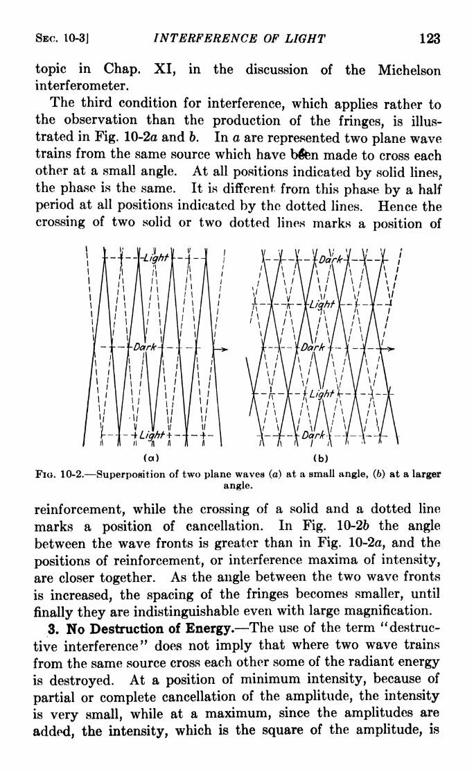
SEC. 10-3] INTERFERENCE OF LIGHT 123
topic in Chap. XI, in the discussion of the Michelsoninterferometer.
The third condition for interference, which applies rather to
the observation than the production of the fringes, is illus-
trated in Fig. 10-2ct and b. In a are represented two plane wavetrains from the same source which have b&n made to cross eachother at a small angle. At all positions indicated by solid lines,
the phase is the same. It is different from this phase by a half
period at all positions indicated by the dotted lines. Hence the
crossing of two solid or two dotted lines marks a position of
FIG. 10-2.-
ii
(a) (b)
-Superposition of two plane waves (a) at a small angle, (6) at a larger
angle.
reinforcement, while the crossing of a solid and a dotted line
marks a position of cancellation. In Fig. 10-26 the angle
between the wave fronts is greater than in Fig. 10-2a, and the
positions of reinforcement, or interference maxima of intensity,
are closer together. As the angle between the two wave fronts
is increased, the spacing of the fringes becomes smaller, until
finally they are indistinguishable even with large magnification.
3. No Destruction of Energy. The use of the term "destruc-
tive interference" does not imply that where two wave trains
from the same source cross each other some of the radiant energy
is destroyed. At a position of minimum intensity, because of
partial or complete cancellation of the amplitude, the intensity
is very small, while at a maximum, since the amplitudes are
added, the intensity, which is the square of the amplitude, is

124 LIGHT: PRINCIPLES AND EXPERIMENTS [CHAP. X
correspondingly large. Conside^ a region of maxima and minimadue to two wave fronts of eqifeil amplitude a, in which the inten-
sity pattern is that shown graphically in Fig. 10-3. It is required
to find the total illumination over a range from x = to x =k,
as shown by the shaded area. According to eq. 9-9 this will be
given by
/ = f*"*
(2a2 + 2a2 cos
^/ X **(10-1)
where <p is the amount by which the difference of phase between
the interfering wave fronts varies along the wave front between
x and x = k. Since <p is a
linear function of x, we may write
<p= mx (see cq. 9-10). By inte-
grating, we have
. 2a 2 + sin mkm
(10-2)
2a'
Intensify
FIG. 10-3.
Since the interference pattern is
at a maximum at both and k,
km =2ir, the second term on
the right is zero, and the total
illumination in any such area
of the field of view is / = 2a2k.
This is exactly the illumination
in the area if the two waves had combined without interference.
Hence in the phenomenon of interference there is no destruction
of energy, but only a redistribution.
w/4. Methods for Producing Interference. Instruments for
producing interference phenomena may be divided into two
general classes: (A) Those which by reflection, refraction, or
diffraction change the directions of two parts of the wave front
so that afterward they reunite at a small angle; (B) those which,
usually by a combination of reflection and refraction, divide the
amplitude of a section of the wave front into two parts to be later
reunited to produce interference. In both cases the usual con-
ditions for interference must always be observed. In all instru-
ments of class A it is necessary to use either a point source
or a very narrow elongated source such as an illuminated slit

SEC. 10-5] INTERFERENCE OF LIGHT 125
parallel to the intersection of the two wave fronts. With instru-
ments of class A, which may be^characterized as effecting a
division of wave front, diffraction will also usually be observed,
although often the spacing between the maxima and minima of
the diffraction pattern is so large in comparison with the spacingbetween the interference fringes that it is easy to distinguish
between the two effects. In the instruments of class B, which
may be characterized as effecting a division of amplitude in a
more extended portion of the wave front, it is not necessary to
use a point or narrow line source. Since the wave front is
divided in amplitude, if upon reunion corresponding points in the
separate parts are superposed, the first condition for interference
will hold.
While the classification just given is probably the most impor-
tant, all instruments for producing interfejncjg. patterns mayalso be grouped in two other categories, depending upon the
existence or~nonexistence of a (^in^lernentaryjQattejn.In general,
those of class ^n(3ivision of wave front) do notpossess comple-
menlarjrpatterns, while those of classj?
witEjt few^ceptioiis7 do^bssessjhem. Since a more extended
disciissioiTof this distinction involves a description of the details
of each instrument, it will not be carried out here.
5. Young's Experiment. Historically the first true inter-
ference effect to be recognized as such was due to Thomas
Young. It belongs to class A, since the device he used recom-
bined two different parts of the wave front so as to produce
alternate light and dark fringes. His apparatus consisted of a
pinhole to admit the light of the sun, and, in another screen a
short distance away, two pinholes sufficiently close together so
that the light diffracted at the first hole entered both of them.
The arrangement is illustrated in Fig. 10-4.
Diffraction also occurred at each of the two holes in the second
screen, and in the overlapping portions of the diffracted wave
fronts interference was observed. For best results it is more
convenient to use narrow slits instead of pinholes, care being
taken to make all the slits perpendicular to a common plane.
The maxima and minima will then be evenly spaced bright and
dark lines of equal width. The maxima will appear where the
difference of path between the two wave fronts is an even number
of half wave-lengths. Figure 12-136, page 177, in the chapter on

126 LIGHT: PRINCIPLES AND EXPERIMENTS [CHAP. X
diffraction is a photograph of the pattern obtained with Young's
apparatus, using slits instead of pinholes. The large scale
pattern of maxima and minima is due to diffraction, while
interference is responsible for the finer pattern which is most
pronounced in the middle but extends over practically the entire
field.
The analysis of the conditions for the production of this inter-
ference pattern will not be undertaken here. While the results
are strictly due to what has been called interference of light, it is
customary to treat the effects due to two or more parallel slits
as extensions of the diffraction due to one slit. Since it is
somewhat easier to handle the analysis in this way, a more com-
plete discussion will be given in Chap. XII.
'in Region ofinterference
Fia. 10-4. Illustrating Young's apparatus.
Among the devices for obtaining interference by a division
of the wave front into two parts, three will be selected for dis-
cussion, since they illustrate most generally the variety of condi-
tions which may exist. These are the Fresnel mirrors, the
Fresnel biprism, and the Rayleigh refractometer.
6. The Fresnel Mirrors. The first of these is in a sense an
adaptation of Young's apparatus, designed to eliminate as far as
possible the presence of the diffraction pattern due to the narrow
slits in the second screen. It is illustrated in Fig. 10-5. Light
from a source 5, which is usually a narrow illuminated slit,
passes to two mirrors which are inclined at a very small angle,
with their line of intersection parallel to the slit S. The fringes
may be seen by placing the eye near the mirrors so as to receive
the reflected light, but ordinarily an eyepiece will be needed to
magnify them. If monochromatic light is used, its wave length
may be determined. Let a be the angle between the mirrors,
Di the distance from the slit S to the intersection of the mirrors,
Z>2 the distance from the mirrors to the point of observation, and
e the distance between two adjacent bright fringes F\ and F*.

SBC. 10-6J INTERFERENCE OF LIGHT 127
The difference of path between the distances SFi and SF2 is
X. The light appears to come from two virtual sources'&i andSz ,
whose distances from the point of observation are DI -+ D2 ,
and whose linear separation may be called d. Since the, angle
FIG. 10-5. Illustrating the Fresnel mirrors.
between the reflected beams is twice that between the mirrors, to
a sufficient degree of approximation,
2 =(10-3)
Also,
3"5TTTS' (1
-4)
Combining these,
2aeDi
Since all the dimensions on the right-hand side of eq. 10-5 maybe measured with considerable accuracy, a fairly precise value of
the wave-length X may be found. Usually the mirrors are set so
that the angle of incidence is large. In this case the angular aper-
ture subtended at the source slit by each mirror is small, and
diffraction is present. An added drawback is that the diffraction
pattern has approximately the same spacing as the interference
pattern, so that the two are not always distinguishable. A
photograph of the fringes obtained with the Fresnel mirrors is
shown in Fig. 10-6.

128 LIGHT: PRINCIPLES AND EXPERIMENTS [CHAP. X
S
1
I

SBC. 10-7] INTERFERENCE OF LIGHT 129
7. The Fresnel Biprism. A much better device for obtainingthe interference between two sections of a wave front, with
diffraction either largely eliminated or distinctly separated in
appearance from the interference pattern, is the Fresnel biprism,
illustrated in Fig. 10-7. The biprism is usually made of a single
piece of glass so shaped that it is in reality two triangular prismsbase to base, with equal and small refracting angles a. The
biprism is set so that it is illuminated by light from a slit S. In
order that the interference fringes may be distinct, the refracting
edges of the two prisms should be parallel to each other, arid the
u ^J^1
Fio. 10-7. The Fresnel biprism.
intersection of the two inclined faces should be accurately parallel
to the slit.
To find the wave-length X of monochromatic light, it is neces-
sary to know the distance d between the virtual images Si and <S2
from which the rays bent by refraction seem to come, the dis-
tances DI and Z>2, and the separation e of two adjacent bright
fringes in the field of view at the cross hairs. The value of d
may be calculated if the index of refraction n of the biprism and
its refracting angle a are known. Since the angles are small, we
may consider the light to be passing through the prisms at minimum
deviation, whence
n . snsn (10-6)
where 5 is the angle of deviation. Equation 10-6 may be put
in the form
. a .a d . a . 8n sm jr
** sm -x cos 5 4- cos75sm =;'
i i i ft ft
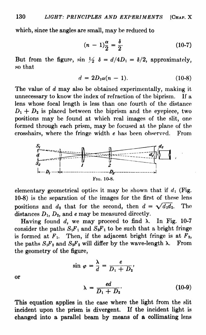
130 LIGHT: PRINCIPLES AND EXPERIMENTS [CHAP. X
which, since the angles are small, may be reduced to
= - (10-7)
But from the figure, sin l d = d/4Di = 5/2, approximately,so that
d = 2Dia(n-
1). (10-8)
The value of d may also be obtained experimentally, making it
unnecessary to know the index of refraction of the biprism. If a
lens whose focal length is less than one fourth of the distance
#1 + DZ is placed between the biprism and the eyepiece, two
positions may be found at which real images of the slit, one
formed through each prism, may be focused at the plane of the
crosshairs, where the fringe width e has been observed. From
Si
S
&
FIG. 10-8.
elementary geometrical optics it may be shown that if d\ (Fig.
10-8) is the separation of the images for the first of these lens
positions and e?2 that for the second, then d = \/didz . The
distances D\, D2 ,and e may be measured directly.
Having found d, we may proceed to find X. In Fig. 10-7
consider the paths S\Fi and SzFi to be such that a bright fringe
is formed at FI. Then, if the adjacent bright fringe is at F2 ,
the paths SiFz and SzFz will differ by the wave-length X. Fromthe geometry of the figure,
8m * =d=
or
This equation applies in the case where the light from the slit
incident upon the prism is divergent. If the incident light is
changed into a parallel beam by means of a collimating lens

SBC. 10-7] INTERFERENCE OF LIGHT 131

132 LIGHT: PRINCIPLES AND EXPERIMENTS [CHAP. X
after leaving the slit, Di is very large compared to >z, so that the
latter may be ignored, and eq. 10-9 becomes
ed
Substituting in this the value of d given in eq. 10-8,
X =
or, finally,
X = 2ea(n - 1). (10-10)
But for small prism angles a(n 1)=
6, the angle of deviation,
so that
X = 2e8. (10-11)
The fringes obtained with a biprism are shown in Fig. 10-9.
f. The Rayleigh Refractometer. This instrument, illus-
trated in Fig. 10-10, has been used extensively for the determina-
^ ^
Fio. 10-10. The Rayleigh refractometer. The figure in the circle illustrates
the arrangement of the compensating mirrors; B\ and Bz are in front of the tubes,
while Ba is below them.
tion of indices of refraction of liquids and gases. While it
possesses some of the general features of Young's apparatus, as
do the Fresnel biprism and mirrors, there are important differ-
ences to be noted. In the Rayleigh refractometer the two inter-
fering beams are originally at a large angle when they leave the
source Si, while in Young's apparatus they travel over nearly
adjacent paths in a diffracted beam. In the second place, the
two portions of the wave front passing through the slits <Sa and S*

SEC. 10-8] INTERFERENCE OF LIGHT 133
are collimated by a lens L\ so that they remain parallel for somedistance. They then pass through a second lens Z/2, placed some
distance from the first, which focuses the two beams, forming an
image of the slit S\ at its principal focus. This image will,
however, be a wide diffraction pattern similar to that shown in
Fig. 12-14, page 179, with fine interference fringes superposed
upon it. The greater the distance between Sz and $2', the finer
will be the interference fringes. Since focusing in only one planeis required, the eyepiece E may be a cylinder with its axis parallel
to the slits. Since this has a magnification in only one plane it
gives a brighter image. The distance between LI and L2 is
made great enough, and the separation of Si and Sz is made wide
enough, so that two tubes containing liquids or gases whose
indices are to be compared may be placed side by side in the
paths of the beams. The glass windows at the ends of these
tubes must be of good optical glass with accurately plane faces.
A change in the index of refraction of the substance in the
tubes may be found as follows : Let us suppose that the two tubes
contain a gas under the same conditions of pressure and tempera-ture. Given equal lengths, the optical paths are equal. A slight
change in the conditions in one tube will cause a change in the
optical path there, and hence a displacement of the fringes. Ameasurement of the amount of this shift, which under actual
conditions is very small, is difficult and subject to uncertainty
because of the narrowness of the fringes. Instead, it is customaryto make use of a so-called coincidence method. At B\ and B 2
in the paths of the beams are placed two plane- parallel plates
of optical glass, of the same thickness, each at an angle of about
45 deg. to the vertical. Under these conditions the optical paths
through them are the same and will produce no displacement of
the fringes. If, however, the index of refraction of the gas, and
hence the optical path through B\ tis altered, the fringes, having
been shifted on that account, may be brought back to their
original position by a rotation of B\ about a horizontal axis
perpendicular to the length of the tubes. Wheri this rotation is
made, the optical path through B\ will be changed by an amount
which is a measure of the index change. In order to provide a
fiducial position to which the fringes may be brought back each
time, there is placed across the lower part of the field, below the
level of the tubes, a plate of glass B 3 ,whose retardation is the

134 LIGHT: PRINCIPLES AND EXPERIMENTS [CHAP. X
same as that of #2 . Through this may be observed a set of
fringes undisturbed by any changes in the tubes. The presenceof this set of fringes as a fiducial system renders the use of a
cylindrical eyepiece necessary, since one of the ordinary type will
result in the superposition of all rays from a single source point,
whether they pass through the tubes or below then %It is
desirable to use white light, as the central bright fringe is easily
identified, while over a considerable range all monochromatic
fringes look alike. Moreover, because of selective absorptionin the tubes, the fringes in the upper and lower parts of the field
of view may not be the same in appearance. This makes it
difficult to find accurately the fractional part of a fringe in white-
light fringes, which are colored except for the central fringe. On
(a)
FIG. 10-11.
this account it is customary to locate the central fringe of the
system in white light, and substitute monochromatic light to
measure the fractional part of a fringe. The motion of plate Bi
must be controlled and calibrated with extreme accuracy bymeans of a micrometer screw. 1
The Rayleigh refractometer has some serious drawbacks.
It will be seen in the discussion of the Michelson interferometer
that these are inherent in interference apparatus of class A, and
are absent when those of class B arc used. On the other hand,
the Rayleigh refractometer in its most modern form is still used
a great deal for measurements of refractive, index, and at least
one portable instrument is on the market.' The principal draw-
back is that the slits S2 and >S2' must be put as far apart as possible
so that tubes of sufficient width may be used. It is also desirable
that the tubes be sufficiently far from each other so that the
physical conditions in them may be controlled separately. Onthe other hand, the farther apart the slits are, i.e., the greater
1 In some forms of this instrument BI and Ba are fixed at right angles
and turned together about a horizontal axis.

SEC. 10-9] INTERFERENCE OF LIGHT 135
the angle their separation subtends at the primary slit Si, the
finer will be the fringes. The resulting loss of intensity whenthese are magnified makes measurements difficult. One of the
most useful devices for increasing the separation of a pair of
interfering beams without increasing the angle subtended at the
primary slit is the biplate illustrated in Fig. 10-1 la. An ingenious
application of the principle of the biplate has been made by W. E.
Williams in a modification of the Rayleigh refractometer. l
9. The Williams Refractometer. The essential feature of
this instrument is illustrated in Fig. 10-116. Instead of passing
through two narrow slits, each of width a, the light after collima-
tion passes through a slit of width 2a and is then divided into
equal parallel beams by refraction through a five-sided prism.
Thus the beams are separated by a distance w which depends on
the size of the prism. Williams has shown that with this arrange-
ment the primary slit Si may be opened to a width Q.715w/atimes the maximum value used in the Rayleigh refractometer,
resulting in a considerable increase in the intensity of the fringes,
which permits greater accuracy of measurement.
Problems
1. The light from a straight incandescent filament falls on two parallel
slits separated by 0.2 mm. If the interference fringes on a screen 75 cm.
away have a spacing of 2.2 mm., what is the wave-length of the light
used?
2. One of the tubes of a Rayleigh refractometer is filled with air, the
other being evacuated. Then the second is filled with air under the
same conditions of temperature and pressure and 98 fringes are seen to
pass the field of view. What is the index of refraction of the air if
sodium light is used and the tubes are each 20 cm. long?
3. What will be the angle of tilt of the compensating plate required to
restore the fringes to their original condition, in the preceding problem,
if the plate has a thickness of 5.1 mm.? (Use n = 1.5 and derive an
equation similar to that used in Experiment 10.)
4. The interference pattern shown in Fig. 10-9 is twice the size of the
original photograph. If the biprism was 35 cm. from the slit, and the
photographic plate 448 cm. from the biprism, what was the wave-length
of the light used? (NOTE: the diifraction patterns also shown in the
photograph, on either side, are those due to the common base of the
1 WILLIAMS, W. E., Proceedings of the Physical Society of London, 44, 451,
1932.

136 LIGHT: PRINCIPLES AND EXPERIMENTS [CHAP. X
prisms. By measurements of their separation, the distance d in eq. 10-9
may be obtained.)
5. A Fresnel biprisrn, in which the refracting angles are 2 deg. and
the index of refraction is 1.5, receives from a narrow slit the light of the
mercury green line, 5461 angstroms. A soap film is placed in the pathof the light which has passed through one of the prisms, and the inter-
ference fringes shift 3.5 fringes. What is the- thickness of the film in
millimeters? (Assume n = 1.33 for the soap solution.)

CHAPTER XI
INTERFERENCE OF LIGHT DIVISION OF AMPLITUDE
In Chap. X it was pointed out that in general there are two
ways of producing interference of light: (A) By a division of the
wave front into two or more sections restricted in width, whichare later recombined, and (B) by a division of amplitude of a
more or less extended portion of the wave front into beams whichare afterward recombined to produce interference. The first
of these methods has been illustrated in Chap. X by Young's
apparatus, the Fresnel biprism and mirrors, and the Rayleighrefractomcter.
1. *6olors in Thin Films. Perhaps the simplest example of
the division of amplitude is the colors in thin films. A simpledevice showing this type of interference is a pair of plane glass
plates pressed close together at one edge and separated by a verythin sheet of foil at the opposite edge, so that the enclosed
air film is in the shape of a wedge. In Fig. 11-1 is a sketch of the
arrangement, and in Fig. 11-16 is a photograph of fringes obtained
with it. In the sketch the angle of the wedge is much exagger-ated. Also, for simplicity the changes of wave-length and direc-
tion which take place in the glass because of refraction are ignored.In Fig. 11-16 the slight curvature of the fringes is due to unequal
pressure on the ends of the plates, which were bent a little by
cjamping.2. Newton's Rings. The first accurate measurements of
interference fringes were made by Newton, although he did not
recognize in the phenomenon of Newton's rings the superpositionof two wave fronts. Instead, he proposed an explanation based
on a corpuscular theory of radiation, making certain assumptionsas to the manner in which the reflection and refraction of the
light took place.
The rings are obtained when two plates of glass having slightly
different curvatures are pressed together so that they touch at one
point. The thin wedge-shaped film of air enclosed between the
plates provides a path difference between the two reflected'
137

LIGHT: PRINCIPLES AND EXPERIMENTS [CHAP. XI*
beams (see Fig. 11-3) of at most a few waVe-lengths, so that the
fringes may be observed with white light. If one of the glass
plates is accurately plane and the other slightly convex and
spherical, the fringes are concentric rings of color.
It is perhaps less complicated to consider first the generalcase of interference in the case of films instead of proceeding at
once to the particular case of Newton's rmcrs. Althoiiffh in
(a) (6)
FIG. 11-1. Interference fringes with a wedge-shaped film of air enclosed
between two plane plates. The fine lines in the photograph are due to scratches
on the glass plates, which were old interferometer plates.
the following derivations the phase difference, and hence the
interference, between beams will be referred to, it must be kept in
mind that the interference is actually between pairs of wave
fronts which owe their presence to a division of amplitude of the
primary wave front incident upon the apparatus.
Consider light to be incident in air upon a thin film of trans-
parent medium having plane-parallel surfaces, an index of refrac-
tion /i, and a thickness e, as illustrated in Fig. 11-2. While the
beam reflected at A is proceeding toward G, that refracted at Aand reflected at B must traverse the path ABA'. Hence the
difference of path at any front as indicated by the line A'F, drawn

SEC. 11-2] DIVISION OF AMPLITUDE 139
normal to AG and A'H, will^be (AB + BA'} - AF. But this
is equal to 2ep cos i* where i is the angle at which the ray strikes
the surface BB'. If, then, the two reflected rays are brought to
a focus on a screen by means of a lens, it
appears that there would be a maximum of
intensity when 2eju cost' = nX, and a mini-
mum when 2ejj, cos i1 = (n -j- M)^> where
n is an integer representing the number of
waves in the difference of path. Actually,
however, the conditions of reflections are
not the same at A and B. At A the reflec-
ritakes place in air from the bounding
face of a denser medium, while at B the
rejection is in the denser medium from a
bounding surface of air. It has been found
by experiment that in the former case there
is a change of phase of IT, corresponding to
a path difference of X/2, while in the latter
case there is no change of phase, so that the
situation is exactly opposite to that stated above, and the beams
AG and 4/# will reinforce each other to produce a maximum when
(11-la)
(11-16)
K
cos i' (n -f-
while they will produce a minimum when
2eiJ. cos i' = nX.
On the other hand, since the transmitted rays BJ and B'K
suffer no difference of phase, they will reinforce each other when
2e/i cos i' = wX,
and counteract each other when
cos (n -f (11-26)
In the case of Newton's rings, eqs. 11-la and 11-16 will hold
for reflected light, provided /* is put equal to unity, since the
two interfering reflections take place with opposite phase exactly
as in the case described above.
The radius of any ring may be found as follows: Let r (Fig.
11-3), be the radius of curvature of a curved glass surface AOMwhich rests upon a plane glass surface OB. Then, since LA is

140 LIGHT: PRINCIPLES AND EXPERIMENTS [CHAP. XI
nearly the same as OB, and AB is nearly the same as e, the
separation between the two surfaces at B, it follows that
_(r_ 6)2 -f
where p is the radius of the fringe caused by the interference
of the two beams, one reflected
from the upper surface at A, the
other from the lower surface at B.
Since e must be small compared to
the other dimensions for the third
condition for interference to bo
fulfilled,
p2 = 2re
to a sufficient degree of apprwria-tion. But by eq. 11-1, when /u is
unity
(n2e =
COS 7,
FIG. 11 -3. -Illustrating the for-for a bright .fringe, and hehc<
mation of Newton s rings. The .
curvature of AOM is exaggerated;actually i at A and B would be p
2 = -- '.j|-*' ..y
almost the same. COS
For small angles i\ cos i' is approximately unity, aj
of the fringe is given by
where n has the values 0, 1, 2, 3, etc., for the first ,
etc., rings, respectively. The radius of a dark fringi
given by
P (11-5)
Since for n =0, by eq. 11-5, p = 0, for reflected light there will
be a dark spot at the center of the fringe system. Also, the
radii of the dark fringes are proportional to the square roots of
whole numbers. Similarly, for the transmitted light, there will
be a bright spot at the center, and the radii of the bright rings
are proportional to the square roots of whole numbers. Thus
the interference patterns produced by reflection and trans-
mission are complementary.

SBC. 11-2] DIVISION OF AMPLITUDE 141
A photograph of Newton's rings obtained with monochromatic
light is shown in Fig. 11-4.
If the upper plate is made of glass of a smaller index of refrac-
tion than the lower one and a liquid of intermediate index is
placed between them, the pattern obtained by reflection will bo
complementary to that obtained with an air film between the
plates, since at each interface the reflection will take place in a
medium of a given index at the bounding surface of one of higher
FIG. 11-4. Photograph of Newton's rings obtained with an uncemented
achromat. The white spot occurs at the center because the two surfaces were
slightly separated there.
index of refraction, and in both cases a change df phase of ir
will occur,
The pattern obtained by transmission is not as easy to see
as that obtained by reflection, since the light transmitted is
much greater than that reflected, resulting in a background of
light against which the interference pattern is dimly observed.
It is desirable that the surfaces for producing Newton's rings
be clean and free from oxidation. In order that the best results
may be obtained it is necessary that the glass surfaces be freshly
ground and polished, since the films which develop with age are
not removable by ordinary means. 1
1See, for instance, a brief paper on this subject by W. W. Sleator and
A. E. Martin in the Journal of the Optical Society of A im-rica 24, 29, 1934.
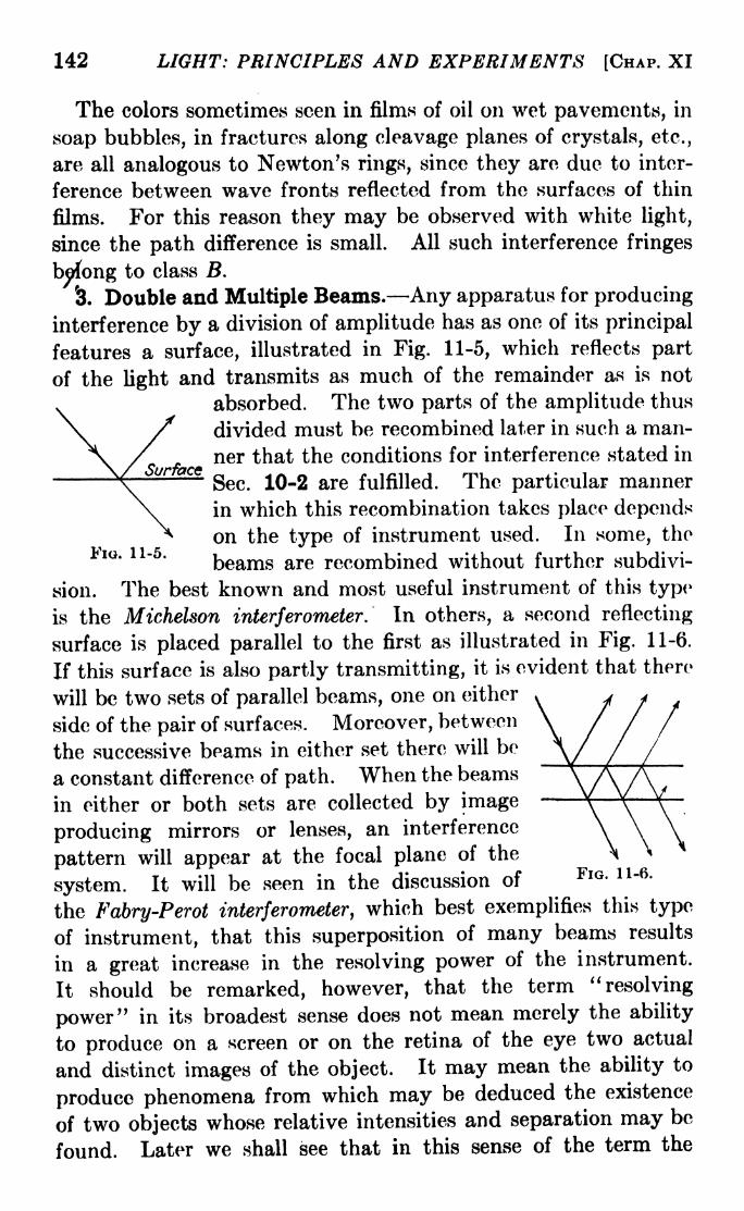
142 LIGHT: PRINCIPLES AND EXPERIMENTS [CHAP. XI
The colors sometimes seen in films of oil on wet pavements, in
soap bubbles, in fractures along cleavage planes of crystals, etc.,
are all analogous to Newton's rings, since they are due to inter-
ference between wave fronts reflected from the surfaces of thin
films. For this reason they may be observed with white light,
since the path difference is small. All such interference fringes
belong to class B.
'3. Double and Multiple Beams. Any apparatus for producing
interference by a division of amplitude has as one of its principal
features a surface, illustrated in Fig. 11-5, which reflects part
of the light and transmits as much of the remainder as is not
absorbed. The two parts of the amplitude thus
/ divided must be recombined later in such a man-' ner that the conditions for interference stated inarace
^^ ^^ ^^ fulfilled. The particular mariner
in which this recombination takes place depends
on the type of instrument used. In some, theFIG. 11-5.
beams are recombined without further subdivi-
sion. The best known and most useful instrument of this type
is the Michelson interferometer. In others, a second reflecting
surface is placed parallel to the first as illustrated in Fig. 11-6.
If this surface is also partly transmitting, it is evident that there
will be two sets of parallel beams, one on either
side of the pair of surfaces. Moreover, between
the successive beams in either set there will be
a constant difference of path. When the beams
in either or both sets are collected by image
producing mirrors or lenses, an interference
pattern will appear at the focal plane of the
system. It will be seen in the discussion of FlG - u "6 '
the Fabry-Perot interferometer, which best exemplifies this type
of instrument, that this superposition of many beams results
in a great increase in the resolving power of the instrument.
It should be remarked, however, that the term "resolving
power" in its broadest sense does not mean merely the ability
to produce on a screen or on the retina of the eye two actual
and distinct images of the object. It may mean the ability to
produce phenomena from which may be deduced the existence
of two objects whose relative intensities and separation may be
found. Later we shall see that in this sense of the term the
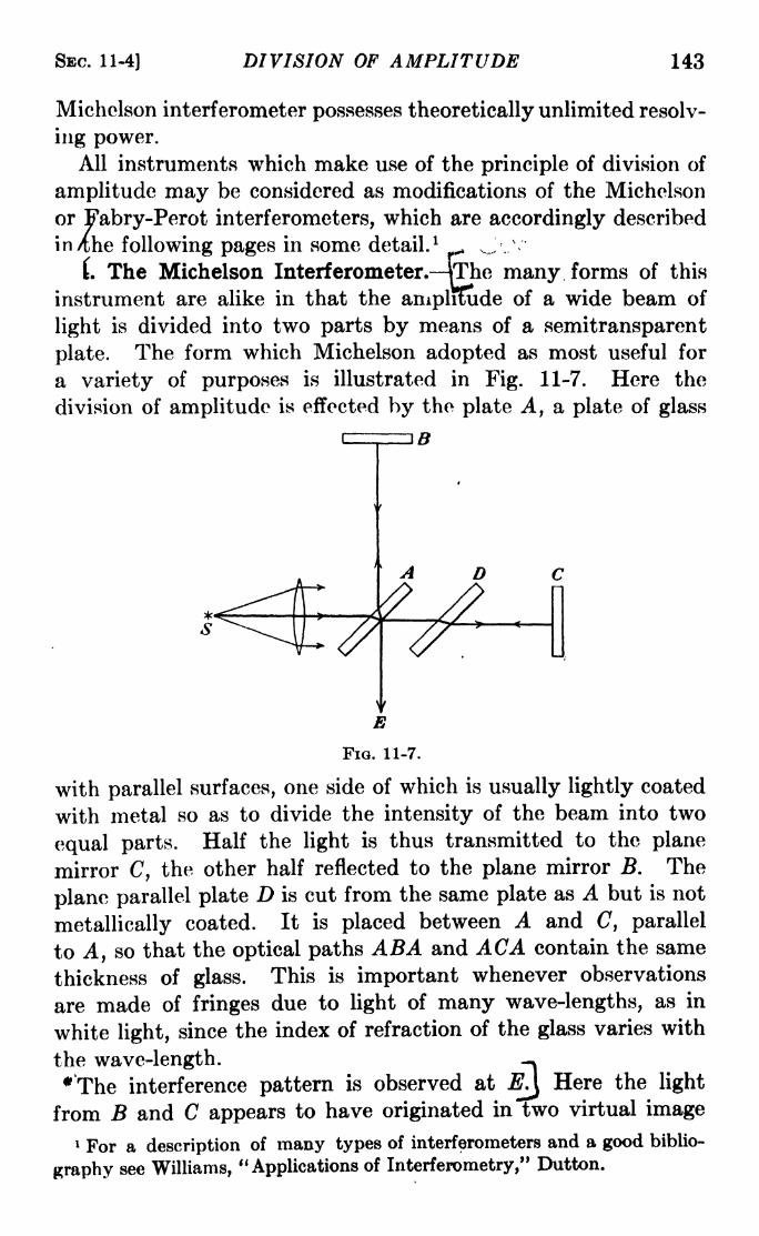
SEC. 11-4] DIVISION OF AMPLITUDE 143
Micholson interferometer possesses theoretically unlimited resolv-
ing power.All instruments which make use of the principle of division of
amplitude may be considered as modifications of the Michelson
or Fabry-Perot interferometers, which are accordingly described
in /the following pages in some detail. 1 _ v,,/.v
. The Michelson Interferometer. VThe many forms of this
instrument are alike in that the amplitude of a wide beam of
light is divided into two parts by means of a semitransparent
plate. The form which Michelson adopted as most useful for
a variety of purposes is illustrated in Fig. 11-7. Here the
division of amplitude is effected by the plate A, a plate of glass
Fia. 11-7.
with parallel surfaces, one side of which is usually lightly coated
with metal so as to divide the intensity of the beam into two
equal parts. Half the light is thus transmitted to the plane
mirror C, the other half reflected to the plane mirror B. The
plane parallel plate D is cut from the same plate as A but is not
metallically coated. It is placed between A and C, parallel
to A, so that the optical paths ABA and ACA contain the same
thickness of glass. This is important whenever observations
are made of fringes due to light of many wave-lengths, as in
white light, since the index of refraction of the glass varies with
the wave-length. -*
*'The interference pattern is observed atJ0J
Here the light
from B and C appears to have originated in two virtual image
1 For a description of many types of interferometers and a good biblio-
graphy see Williams, "Applications of Interferometry," Dutton.

144 LIGHT: PRINCIPLES AND EXPERIMENTS [CHAP. Xl
planes situated in the neighborhood of B. We may consider one
of the virtual image planes to be Mi (Fig. 11-8). Let Mi be
the plane which replaces mirror B. If Mz is, likewise, the plane. which replaces mirror C in the field of view,
-M2 then the virtual image due to the light from~M* C must be in a plane Mi which makes an
FIG. 11-8.angle with Mi twice that between Mi and
1 Thus for purposes of analysis the mirrors B and C are
replaced by two virtual image planesM i and Mi, and the interfer-
ometer is considered as a pair of plane wave fronts with an air space
between them. If the distances from A to B and A to C are
not equal, and if B and C are not at right angles, these wave
FIG. 11-9.
fronts will be as shown in Fig. ll-9jmt is desired to find the
character of the fringes formed at some point P. The first
step is to find the path difference between the two virtual wave
fronts. 2
The following notation will b* used:
D = the distance from a point P, where the interference
fringes are formed, perpendicular to the planes Mi and
Mi, which must for the production of fringes be at such a
small angle that they can be considered to have a com-
mon perpendicular.
2<f>= the small angle between the surfaces, in a plane perpen-
dicular to their line of intersection. The plane in which
1Since, when a reflector is turned through an angle, the reflected beam is
turned through twice that angle.2 The derivation given here is essentially that presented by Michelson in
Philosophical Magazine, (5), 13, 236, 1882.

SEC. 11-4] DIVISION OF AMPLITUDE 14ft
this angle lies will depend on the adjustment of
mirrors A and B.
d = the angle between the perpendicular D and the line
joining P and a\.
i = the projection of the angle 5 on a plane containing 2<p.
= the projection of the angle 5 on a plane perpendicularto that containing 2<p.
A = the difference of path between the distance a\P and 6iP.
2t = the distance a b .
2t = the distance a\b\.
The planes Pb and ai&i are two parallel lines which define a
plane in which the angle 8 lies; hence,
1 A = aibi cos 5 = 2t cos d. (11-6)~
But 2t = 2to + a\c tan 2<p, or, since a\c = D tan i,<
t to + D tan <p tan i
to a sufficient degree of approximation since the angles are small.
Substituting this value of t in eq. 11-6,
A =(2*o + 2D tan <p tan i} cos 6. (11-7)
ButD
tan 2 i -fcos 5 =
$
Hence,
A = *- (11-8)VI + tan 2
i + tan 2
'^>
Thus we see that the path, and hence the phase, difference
between the two beams a\P and biP may vary over the area of
the wave front contributing to the fringes at P, and the phenome-non of interference may be obliterated. If the sizes of the
angles <p, i, and 8 are restricted sufficiently so that the maximumvalue of A is X/2 or less a single phase will predominate and the
fringes will be distinct. In most cases the pupil of the eye places
a sufficient restriction on i and 0, provided it is at a suitable
distance from the interferometer, so that the fringes are easily
seen. Sometimes the use of a pinjiole in front of the eye will
improve the visibility of the fringes

146 LIGHT: PRINCIPLES AND EXPERIMENTS [CHAP. XI
5. The Distinctness of the Fringes. The fringes will be most
distinct when dA/d0 and d&/di are both zero. Imposing on
eq. (11-8) these two conditions gives
D - fc*ELi, (ll_9)tan <p^ '
for the distance between P and the position of the surfaces for
which the fringes will be most distinct. An examination of
eq. 11-9 shows that if U = then D =0, and the fringes will be
best at the surface of B (Fig. 11-8). This means that if the eye is
placed at normal reading distance from the mirror J5, the fringes
will appear distinct when the lengths of the optical paths in the
two arms of the interferometer are the same. Equation 11-9
also says that when i is zero, D is zero, which is another way of
saying that the area of the wave front is sufficiently restricted in
a direction perpendicular to the intersection of the two wavefronts so that no troublesome confusion of phases exists. If
<p is zero, the wave fronts are parallel, i.e., the mirrors are at
right angles; if also to is zero, the optical paths in the two arms of
the interferometer are the same and also the mirrors are per-
pendicular, and over the entire field the two wave fronts will
cancel each other. If <p and i have the same sign, D is positive,
and the fringes are formed in front of the mirror B', if they
ha^ve opposite sign, D is negative and the fringes lie behind B.
6. The Form of the Fringes. Any point on the plane where
thlffringes are formed may be described by the equations
x D tan i
y = D tan (
Substituting these values in eq. 11-8, we obtain the general
equation for the form of the interference fringes,
Ay = (4D2 tan2
<p- A2
)z2 + (StoD
2 tan <p)x + D2(W - A 2).
(11-11)
An analysis of this equation shows 1 that the fringes take the
forms of straight lines, circles, parabolas, ellipses, or hyperbolas,
depending on the values assigned to A and <p. The complete
theory will not be discussed here; certain details are, however,
worthy of attention since they bear directly upon the successful
1 SHEDD, JOHN C., Physical Review, 11, 304, 1900; also Mann, "Manual of
Optics," Ginn.

SEC. 11-71 DIVISION OF AMPLITUDE 147
use of the instrument. For A =0, eq. (11-11) becomes
* = T-^-> (11-12)tan<f>
v '
which is the equation of a straight line. This is the central
fringe of the system of fringes obtained with a white-light source.
Those on either side of it, corresponding to A very small, will be
curved in opposite directions on either side of the central fringe,
although the curvature is not noticed for the few fringes which
occur with a white-light source. The curvature is scarcelynoticeable with a monochromatic source within the relatively
small area of the field of the instrument unless A is large enoughto correspond to about 100 fringes from the central fringe. Bymoving the mirror B back and forth rapidly about the positionfor A =
0, the change of curvature may be detected. This
maneuver constitutes one method of finding approximately the
center of the fringe system. With the limits of the position for
B thus determined, white light may be substituted for the mono-chromatic source, and the mirror moved very slowly until the
white-light fringes come into the field of view.
If(f>=
0, eq. 10-11 becomes
2
- A 2)
x z + y- = - ---, (11-13)
which is the equation of a circle. Hence, when the virtual source
images are parallel, the fringes will be circular inform5j As A
becomes small, the diameters of the circles will become large,
until for A =0, the entire field will be either dark or bright. In
theory it will be dark for A =0, since the reflection of the
two beams at the dividing plate A introduces a difference of
phase of ir, and a difference of path of X/2. Actually, however,a field entirely dark is difficult to observe since very slight irregu-
larities in the metallic coats, lack of planeness of the glass
surfaces, or inhomogeneity in the glass may have an effect
which is of maximum observability for this adjustment of the
interferometer. The field will in general be dark, with irregular
streaks and patches of light showing.
7. The Visibility of the Fringes. Visibility Curves. Althoughthe Michelson interferometer was originally designed as a refrac-
tometer to measure the relative difference of path introduced
into the two arms of the instrument by a change in the medium.
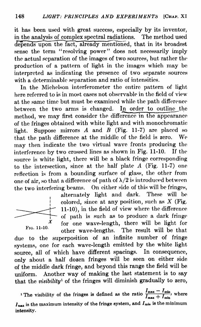
148 LIGHT: PRINCIPLES AND EXPERIMENTS [CHAP. XI
it has been used with great success, especially by its inventor,
in the analysis of_cpmplex spectral radiations. The method used
depends Tipon the fact,"already mentioned, that in its broadest
sense the term "resolving power" does not necessarily implythe actual separation of the images of two sources, but rather the
production of a pattern of light in the images which may be
interpreted as indicating the presence of two separate sources
with a determinable separation and ratio of intensities.
In the Michelson interferometer the entire pattern of light
here referred to is in most cases not observable in the field of view
at the same time but must be examined while the path difference
between the two arms is changed. In order to outlinc^the
method, we may first consider the difference in the appearance
of the fringes obtained with white light and with monochromatic
light. Suppose mirrors A and B (Fig. 11-7) are placed so
that the path difference at the middle of the field is zero. Wemay then indicate the two virtual wave fronts producing the
interference by two crossed lines as shown in Fig. 11-10. If the
source is white light, there will be a black fringe corresponding
to the intersection, since at the half plate A (Fig. 11-7) one
reflection is from a bounding surface of glass, the other from
one of air, so that a difference of path of X/2 is introduced between
the two interfering beams. On either side of this will be fringes,
alternately light and dark. These will be
colored, since at any position, such as X (Fig.
11-10), in the field of view where the difference
of path is such as to produce a dark fringe
for one wave-length, there will be light forFIG. 11-10.
other wave.lengtjls xhe result will be that
due to the superposition of an infinite number of fringe
systems, one for each wave-length emitted by the white light
source, all of which have different spacings. In consequence,
only about a half dozen fringes will be seen on either side
of the middle dark fringe, and beyond this range the field will be
uniform. Another way of making the last statement is to say
that the visibility1 of the fringes will diminish gradually to zero,
1 The visibility of the fringes is defined as the ratio ,"", /" > where
'max T" 'mlnmln
is the maximum intensity of the fringe system, and /,, is the minimum
intensity.

SBC. 11-7] DIVISION Ob' AMPLITUDE 149
so that beyond a half dozen on either side of the central minimumnone will be seen. On the other hand, if.strictly..mongchrgmatic
light is used, there will be no dimi-
nution of the visibility ofthe fringes,
no matter how far away from the
central dark fringe they are exam-
ined. These details are illustrated
with a fair degree of exactness in
Fig. 11-11, in which (a), (6), and (c)
are photographs obtained with red,
green, and blue monochromatic
radiations, respectively, and (d) is
the photograph of the white-light
fringes due to the superposition of
all the radiations from a white-light
source. Although the range of sen-
sitivity of the eye is not the sameas that of the photographic plate,
Fig. 11-1 Id approximates closely
the visual appearance of white-light
fringes -
Center
Figure 11-12 illustrates the Fro. ll-ll Interference fringes
effect produced by narrowing the with a Mi<>helson interferometer.
spectral range of white light. In a are shown the fringes due
to the entire range of wave-length in a white-light source, while
in 6 are shown those obtained when a filter is interposed, which
(a) (ft) (c)
FIG. 11-12. (a) White light fringes. The arrows point to the central dark
fringe. (6) Fringes with white light through a filter which transmitted a bandof about 100 angstroms. The arrows point to the central dark fringe, (c)
Fringes with the green line of mercury, 5461 angstroms.
permits the passage of a band of light of only about 100 ang-
stroms. In Fig. ll-12c are shown the fringes, with the same

150 LIGHT: PRINCIPLED AND EXPERIMENTS [CHAP. XI
adjustment of the interferometer as in a and 6, from the green
mercury line, whose wave-length is 5461 angstroms.If the light incident upon the interferometer is composed of
two radiations, the visibility of the fringes will pass throughalternations whose spacing will depend upon the ratio of the two
wave-lengths. If this ratio is large, the alternations will occur
rapidly, as illustrated in Fig. ll-13a and 6. In a is shown the
effect due to the superposition of the fringes of the two mercurylines 5461 and 4358 angstroms, and in b is shown the effect due
to the mercurv lines 5461. 5770. and 5790 ano-stroms. The
(a) (b)
FIG. 11-13. Interference fringes (a) with X4358 and X6461; (6) with X5461 andthe two yellow mercury lines X5770 and X5790.
last two are so nearly alike that in the field of view they have the
effect of a single radiation.
Thus far in the discussion of visibility, the effect due to indi-
vidual spectral lines has been treated as though each such radiation
were monochromatic. Actually, however, there is no such thing
as a completely monochromatic radiation, although in some the
range of wave-length dX is extremely small. Owing to circum-
stances which depend on the nature of the radiating atoms or
molecules and the conditions in the source, even the most nearly
monochromatic radiations have a width rfX, so that with sufficient
difference of path introduced between the two arms of the inter-
ferometer the visibility of the fringes will drop to zero. More-
over, most so-called single spectral lines, such as the mercurylines mentioned in the last paragraph, are composed of several
SEC. 11-7] DIVISION OF AMPLITUDE 151
individual lines whose difference of wave-length is so small that
none but the highest resolving power will make it possible for
them to be observed directly as separate lines. The Michelson
interferometer possesses theoretically unlimited resolving power;
although it does not enable the observer to see this fine structure
of spectral lines directly, the interpretation of the alternations of
visibility just illustrated makes it possible to determine the
presence and character of the fine structure.
No satisfactory method has been developed for determining
accurately changes in visibility by any but visual means. Conse-
quently, Michelson's method of analysis of spectral lines byvisibility curves, while it was the first to yield the structure of
many important radiations, has not progressed beyond the initial
stages developed by its inventor. Other instruments of high
resolving power have taken its place, although the results
obtained by Michelson have in many cases not been surpassed in
accuracy. His method consists essentially in plotting the
visibility graphically as a function of the difference of optical
path between the beams traversing the two arms of the inter-
ferometer. This graph, however, may be regarded as the result-
ant intensity graph of a number of separate intensities. By the
use of specially designed mechanical analyzers, these componentsare found, and the wave-length ratios and relative intensities of
the corresponding individual lines determined. A few of Michel-
son's visibility curves, taken from his published papers, are
shown in Fig. 11-14.
By means of this method, Michelson was able to show that the
red radiation from cadmium vapor was most nearly mono-
chromatic of all those that he examined. Accordingly he
used it as a primary standard of wave-length for comparisonwith the standard meter, using interference methods. 1 This
comparison was carried out first by Michelson, and later byBenoit, Fabry, and Perot with the Fabry-Perot interferometer,
confirming Michelson's measurement. 2 The value of the wave-
1 " D6termination experimeiitale de la valeur du metre en longueurs d'onde
lumineuses." Translated from the English by Benoit. The details are
described briefly in Michelson, "Light Waves and Their Uses," and Michel-
son, "Studies in Optics," both published by the University of Chicago Press.
2 BENOIT, FABRY, and PEROT, Travaux et memoirs Bureau international,
11, 1913.

152 LIGHT: PRINCIPLES AND EXPERIMENTS [CHAP. XI
length of the red cadmium line thus obtained in terms of the
standard meter in dry air at 15C. and 760 mm. Hg pressure is
6438.4696 angstroms. This value has been accepted by inter-
national agreement as a primary standard of wave-length.
(a)
(b)
(c)
0.1 20 40 60 80 100 120 140 160 180200220240mm.
A ff
0.1 0.2 20 40 60 80 100 120 140 160 180 200 220 240 260 280mm.
A B
O.I 20 40 60 80 100 120 140 160 180 200 220 240 260 280 300 320mm.
A B
1.0
0.5
0.1 0.2
A0.3 0.4 10 20 30mm
Fio. 11-14. Michelson's visibility curves. In each ease graph B shows the
variation of visibility of fringes with path difference in millimeters, and A showsthe interpretation of B in terms of intensity distribution in the spectral line used
(a) The red cadmium line (primary standard) 6438.4696 angstroms; (b) the
sodium lines 5890 and 5896 angstroms; (c) the mercury line 5790 angstroms; and
(rf) the red hydrogen line, H, 6563 angstroms.
By the use of visiblity curves, Michelson was also the first to
show that the red hydrogen line, 6563 angstroms, is really a very
close double. His result is in good agreement with those obtained
later by the use of instruments of direct resolving power, and
with the structure of the line deduced theoretically by the applica-
tion of the Quantum theorv to the analysis of spectra.
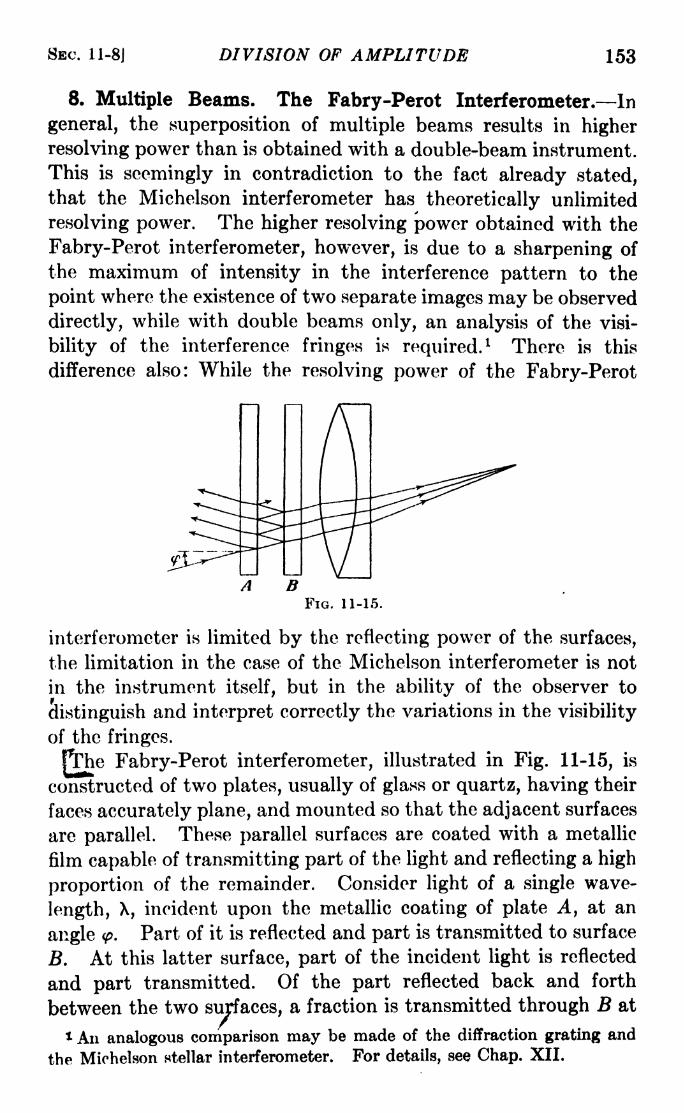
SEC. 11-8] DIVISION OF AMPLITUDE 153
8. Multiple Beams. The Fabry-Perot Interferometer. In
general, the superposition of multiple beams results in higher
resolving power than is obtained with a double-beam instrument.
This is seemingly in contradiction to the fact already stated,that the Michelson interferometer has theoretically unlimited
resolving power. The higher resolving power obtained with the
Fabry-Perot interferometer, however, is due to a sharpening of
the maximum of intensity in the interference pattern to the
point where the existence of two separate images may be observed
directly, while with double beams only, an analysis of the visi-
bility of the interference fringes is required.1 There is this
difference also: While the resolving power of the Fabry-Perot
FIG. 11-15.
interferometer is limited by the reflecting power of the surfaces,
the limitation in the case of the Michelson interferometer is not
in the instrument itself, but in the ability of the observer to
distinguish and interpret correctly the variations in the visibility
of the fringes.
PThe Fabry-Perot interferometer, illustrated in Fig. 11-15, is
constructed of two plates, usually of glass or quartz, having their
faces accurately plane, and mounted so that the adjacent surfaces
are parallel. These parallel surfaces are coated with a metallic
film capable of transmitting part of the light and reflecting a high
proportion of the remainder. Consider light of a single wave-
length, X, incident upon the metallic coating of plate A, at an
angle <p. Part of it is reflected and part is transmitted to surface
B. At this latter surface, part of the incident light is reflected
and part transmitted. Of the part reflected back and forth
between the two surfaces, a fraction is transmitted through B at
1 An analogous comparison may be made of the diffraction grating and
the Michelson stellar interferometer. For details, see Chap. XII.

154 LIGHT: PRINCIPLES AND EXPERIMENTS [CHAP. XI
each incidence upon it. There are similar sets of reflections
due to the surfaces of the plates on which no metal is deposited,
but these surfaces have relatively low reflecting power. It is
customary to make each of the plates slightly wedge-shaped, so
that its two surfaces are at a small angle. This causes anyreflections at the outer, uncoated surfaces to be thrown to one
side so as not to be superposed upon the pattern of fringes
obtained with the inner metal surfaces. This wedge shapeintroduces a slight amount of prismatic dispersion, but not
enough to cause serious difficulty* For angles of incidence
greater than zero, each beam under-
goes a small sidewise displacement
owing to refraction, but this is the
same in both plates for all beams
having the same angle of incidence,
and so may be neglected.
We may thus consider the inter-
ferometer to be essentially a pair of
parallel surfaces of as high reflect-
ing power as possible. By reference
to this simplified concept which is illustrated in Fig. 11-16, we
may readily see that
AD = p\ = 2d cos <p, (11-14)
in which p is the number of wave-lengths in the common differ-
ence of path of consecutive rays such as Ei, Ez, etc., and d is the
separation of the surfaces. We may then call p the order of
interference between thesuccessive
beams E\, Ez ,etc. It should
be emphasized that the focal poinkof these parallel beams will be
the principal focus of the eye lens, in case of visual observation
of the fringes, or of the projecting lens, as shown in Fig. 11-15,
regardless of the manner in which the original beam of light is
projected upon the interferometer. The plane of incidence
represented by the page in Fig. 11-15 is one of an infinite number,
all containing the normal to the reflecting surfaces, hence there
will be a circle of focal points for each angle of incidence <f>.If p
is a whole number, the difference of path between successive
elements will be an integral number of wave-lengths, and the
amplitudes of the successive beams will add to give a maximumof intensity in the form of a circular fringe. Since there will be

SEC. 11-8J DIVISION OF AMPLITUDE 155
for any wave-length several values of <p for which p will be a whole
number, there will correspond to each wave-length a number of
concentric circles of maximum intensity!At the center of the pattern, the intensity will depend on
the difference of path for <f>= 0. For this case, eq. 11-14 becomes
PX - 2d, (11-15)
where P is used to indicate the order of interference at the center
of the ring system, while p is used to indicate the order of inter-
ference for a bnghtfrinee^ExceDtinanoccasional instance,
Fio. 11-17. Fabry-Perot fringes of the mercury line 6461 angstroms.
P is not a whole number, while p is always a whole number.
Provided all wave-lengths undergo the same change of phase on
reflection from the metallically coated surfaces, we may assume
d to be constant, whereupon
PiXi = P2X 2= = constant, (11-16)
so that if the ratios of the P's can be found, the ratios of the wave-
lengths may be calculated. If one of the observed radiations is
either the primary standard, 6438.4696 angstroms, or else a
suitable secondary standard of wave-length, the other wave-
lengths may all be found with a high degree of accuracy. The
use of the Fabry-Perot interferometer for the comparison of
wave-lengths with primary or secondary standards has been
adopted by international agreement for the establishment of
wave-lengths of spectral lines throughout the visible, ultraviolet,
156 LIGHT: PRINCIPLES AND EXPERIMENTS [CHAP. XI
and infrared spectral regions. For secondary standards, the
spectra of iron, copper, and neon are principally used.
The use of the Fabry-Perot interferometer in the measurement
of the length of the standard meter in terms of the wave-length
of the red cadmium line has already been referred to in Sec. 11-7.
The instrument may also be adapted to a number of other uses,
probably the principal one at the present time being the examina-
tion of the fine structure of spectral lines. l A photograph of the
system of fringes of the green mercury radiation, 5461 angstroms,is shown in Fig. 11-17. The composite structure of the line,
which can be found also by the visibility-curve method with the
Micjielsori interferometer, is shown very well.
. Intensity Distribution in Fabry-Perot Fringes. From a
consideration of Fig. 11-16, it is evident that the rate at which the
intensity of the successive parallel beams E\, Ez, E3) etc.,
decreases depends upon the reflecting and transmitting powers
of the metallically coated surfaces. Let Q and R represent
respectively the fractional parts of the incident light intensity
transmitted and reflected at each of the surfaces. Then the
transmitted beam E\ will have an intensity Q2 and an amplitude
Q; beam Ez will have intensity Q2R 2 and amplitude QR; beam #3
will have intensity Q^R* and amplitude QR 2,and so on. The
amplitude of the nth beam will be QRn~ l. Neglecting the small
change of phase on reflection which takes place at the surface
of the metal, the constant difference in phase between successive
beams is
= 8 '
A
The disturbance at any point on the incident wave front may be
represented by
S a cos2-^
= a cos wt.
It is possible, however, to use exponential instead of trigono-
metric expressions with some shortening of the labor involved.
Since e** = cos at + i sin at, the disturbance may be repre-
1 For a fairly complete discussion of the uses of the Fabry-Perot inter-
ferometer, and an excellent bibliography, see Williams, "Applications of
Tnterferometry."

SEC. 11-9] DIVISION OF AMPLITUDE 157
sented by the real part of ***. If the difference of phase between
the successive transmitted beams E\, / 2 , etc., is 6, the total
amplitude of the sum of the beams at any instant will be the
real part of
2 = Qe1^ + QRe**-'* + Q/2V ( '-2*> + (11-18)
This can be put in the form
(1M9)
But the amplitude factor
Q C1 - Re~* 1 - R cos 6 + iR sin 5
_ ~ 1 R cos 6 iR sin 6_ ^_________,
an expression in which the numerator is of the form X iY,
where X = Q(l R cos 5) and Y = QR sin 6. Since this
represents the amplitude of the superposed beams, the intensity
is given by
;(1- R cos 6)
2 + R z sin 2 6
(1 --~272"c()s"6"4-~_22)2
Q 2
(1- 2R cos 6 + /2
8)
1 + 2/2(1- cos 6)
- 2# + R-
Q2
(1- RY + 4/2 sin 2
(6/2)
Q 2 1
(1- RY 4# /Y> '
-f IAjLt1 Of 1'
1 4. _ r>N- . sm- ( ^
(11-20)
When 6 = 0, 2ir, 4?r, etc., sin 2(6/2) =
0, and the maximum
intensity of the fringes is Q 2/(l /2)
2;when 6 = T, Sir, 5ir, etc.,
sin 2(6/2) =
1, and the minimum intensity of the fringe systemis Q2
/(l + /2)2
. It will be seen that the intensity never drops
to zero although it may become very small.
The visibility of the fringes is defined as
7 T
F-* mftx * mjp-f -TTT"* max i^ * min

158 LIGHT: PRINCIPLES AND EXPERIMENTS [CHAP. XI
Hence for the Fabry-Perot fringes, the visibility is
V = -y (11-21)
and thus depends only on the reflecting power of the metal
surfaces, and is independent of their transparency!10. Resolving Power of the Fabry-Perot InteTferometer. By
uuicrentiation, from eq. 11-15, we obtain
P d\ + X dP =0,
from which it follows that the resolving power is
X P
or, the resolving power, defined as the ratio of the wave-lengthto the smallest difference of wave-length which may be detected,
is equal to the order of interference at the center of the ring
system divided by the smallest change of order dP which can be
detected. Actually, since the value for p is different from
that for P, for any given wave-length, by only a small number,
provided one considers a bright fringe only a few rings outside
the center, the actual measurement of dP may be more easily
made on a fringe near the center instead of at the center itself,
since at the center of the pattern the width of the rings is so large
as to render estimates of intensity variation in them difficult.
This point is taken up in detail in Sec. 11-11.
The value of dP may be found from eq. 11-20. Consider two
adjacent bright fringes in the interference pattern, belonging to
two wave-lengths, X and X + d\ between which the difference
of order dP, corresponding to their difference of wave-length d\,
is to be found. It will be shown in the chapter on Diffraction
that, according to. an arbitrary criterion established by Rayleigh,
two images are said to be just resolved when the maximum of
intensity of one of them corresponds in position with the first
minimum of intensity of the other, as illustrated in Fig. 11-18.
This criterion, which agrees very well with experimentally
determined measures of limit of resolution in optical imagery,
was originally set up with regard to spectral-line images producedwith diffraction gratings, and may be considered to hold suffi-
ciently well in the present case. The intensity for either of the

SEC. 11-10] DIVISION OF AMPLITUDE 159
adjacent bright fringes in the Fabry-Perot ring system may be
called /,, and by the last section is equal to Q2/(l jR)
2,while
the intensity at the center of the pattern shown in Fig. 11-18 is,
for either image, given by eq. 11-20. Consequently we may write
1
1
(11-23)
It can be shown from diffraction theory that in case the images
are equal in width and intensity and symmetrical, the intensity
at a point c 2 , midway between the images, will be 8/Tr2
,or about
- dP HFIG. 11-18.
0.81, times the maximum of either, so that the intensity of each
image at the point c2 is 0.405 times the intensity of either at its
maximum. Thus we may write
J = 0.405.
Substituting this value in eq. 11-23, there results
2M _ -0.405) (1
-81
\2/
It should be kept in mind, however, that the minimum inten-
sity of the fringes, given by Q2/(l + #)
2,never drops to zero,
although for heavy metallic coats on the interferometer surfaces
it may become so small that it is negligible for visual observations
and correct photographic exposures. Also, it is not always true

160 LIGHT: PRINCIPLES AND EXPERIMENTS [CHAP. XI
that the fringes of two radiations to be resolved have even approx-
imately the same intensity; consequently the Rayleigh criterion
does not hold with great rigor. Moreover, the Fabry-Perot
fringes are not symmetrical, but are unsymmetrically widened
toward the center of the ring system. Since taking these excep-
tions into account would require a greater departure from simple
theory than is justified in obtaining an expression for resolving
power, which, after all, can only agree approximately with anyobserved value, we may disregard them. Then in the present
case dP in eq. 11-22 may be said to correspond to a change in
phase of IT, since the difference of order of unity between two
fringes corresponds to a difference of phase of 27r. Hence at the
Rayleigh limit of resolution, 5 = TT dP. Substituting this value
of 5 in eq. 1 1-23, we obtain
6 = 2 sin- 10.595(1
-1.627?
so that the resolving power is
X P PTT
-H = dP,
d\ (IP.
, 0.367(1-
2wn~ft 1
From this equation the theoretical resolving power of the Fabry-Perot interferometer may be calculated. The negative sign in
front of the right-hand member may be disregarded, as it means
simply that a positive increase of wave-length corresponds to a
negative change of order dP. For a wave-length of 5,000 ang-
stroms and a mirror separation d of 10 mm., it follows from eq.
1 1-15 that P is 40,000. From eq. 1 1-24 are calculated the resolv-
ing powers shown in the following table:
Reflecting Power, Per Cent Resolving Power
50 139,60075 349,20090 1,047,200
This shows that the resolving power increases very rapidlywith the reflecting power of the metallic coating. Only the best
metallic coats have reflecting powers of 85 per cent or better,
and not all metals are satisfactory for the purpose. Those
most useful for both the visible and near ultraviolet are alumi-

SEC. 11-11] DIVISION OF AMPLITUDE 161
num, chromium, platinum, gold, nickel, and silicon. For the
visible only, silver is very useful, but it possesses a band of almost
complete transmission in the region of 3300 angstroms. Until
recently it has been difficult to obtain uniform deposits, but the
development of the modern evaporating process, outlined in
Appendix V, has resulted in the production of deposits which are
not only more uniform but more durable. In addition, the
evaporating process has made it possible to obtain highly reflect-
ing coats of metals not obtainable by earlier methods. Themost useful metal for all-round purposes is probably aluminum,which is a good reflector over practically the entire available
range of optical spectra and retains its reflecting power for very
long periods.
11. The Shape of the Fabry-Perot Fringes. In the last
section it was stated that the fringes obtained with this inter-
ferometer are not symmetrical about their maxima. This maybe shown in the following manner: Dividing eq. 11-15 by eq.
11-14,
- = = i-/7>v (11-25)
p cos (p cos (a/2)
in which a is the angular diameter of the pth fringe. The cosine
term may be expanded into a series:
COS 1-^1 = 12
~4 -2! 16 -4!
For observations made with a sufficiently small, only the first
two terms of the series are significant, hence eq. 11-25 may be
written
P = 2-j (11-26)
If D is the linear diameter of a fringe, and F is the principal
focal length of a lens or mirror used to focus the fringes, then
a = D/F. Hence eq. 1 1-26 may be written
For a given fringe p is a constant, so that differentiating eq.
162 LI$HT: PRINCIPLES AND EXPERIMENTS [CHAP. XI
11-27 with respect to D, we obtain
dD
On substitution of this value for dP in eq. 11-22, it follows that
d\ dP p D dDwhence
dDd\ ~p\D
'
For any fixed separation of the interferometer surfaces the ratio
P/p is constant for a given X and is practically equal to unity
provided a fringe not too far from the center is taken. We maytherefore write
-5 <*
where K is a constant depending on the wave-length and the
principal focal length of the projecting lens or mirror. Equation11-28 says that the change in diameter of a fringe with wave-
length is inversely proportional to the diameter of the fringe.
For fringes with very small diameters, i.e., for fringes which lie
very close to the center of the system, the change in D with small
changes of X will be very large. This means that the bright
fringes in the pattern, for a single wave-length, will not be
symmetrical in shape, but will be unsymmetrically broadened
toward the center and sharper on the outer edge. Hence in
determining the wave-lengths of spectral lines, it is desirable to
avoid the use of the rings close to the center of the pattern
unless great care is taken to set accurately on the maximum of
intensity of the fringes rather than on the geometric center.
Problems
1. Describe a method by which Newton's rings could be used to
determine the ratio of two wave-lengths 1000 angstroms apart, say 5000
and 6000 angstroms.
2. Between the convergent crown and divergent flint glass elements
of an uncemented achromatic doublet Newton's rings are formed. Whenseen by reflection through the flint element there is a dark fringe at the
center, and the fourth bright fringe has a radius of 1.16 cm. If the

DIVISION OF AMPLITUDE 163
radius of curvature of the crown glass interface is 50 cm., and the inci-
dent light is nearly normal, what is the radius of curvature of the flint
glass face next to it? Assume a wave-length of 5500 angstroms.
3. A Michelson interferometer is adjusted so that white light fringes
are in the field of view. Sodium light is substituted and one mirror
moved until the fringes reach minimum visibility. How far is the mirror
moved?4. A certain spectral line which is a close doublet has a mean wave-
length of 3440 angstroms, and a separation between the components of
0.0063 angstrom. If the mirrors of a Fabry-Perot interferometer have a
reflecting power of 85 per cent, what must be their separation to resolve
the doublet? What resolving power is indicated? Assume the width
of each component to be less than 0.002 angstrom.
6. What is the resolving power of a Fabry-Perot interferometer in
which the separation is 15 mm., for a reflecting power of 75 per cent?
For a reflecting power of 90 per cent? (Assume X = 5000 angstroms.)
6. What will be the effect on the resolving power of a Fabry-Perot
interferometer if one of the plates has a reflecting power of 60 per cent
and the other 80 per cent? Will it make any difference which plate has
the higher reflecting power?

CHAPTER XII
DIFFRACTION
In Sec. 9-9 it was shown that if a plane wave from a distant
point S is incident on a slit of width a, the result will not be a
sharply outlined single image of the slit but a series of images
separated by regions of zero intensity, forming a diffraction pat-
tern. The effect produced by diffraction is not to be confused
with that obtained with an instrument fulfilling the conditions
for interference proper. To be sure, the pattern of maxima andminima in diffraction is due to the reinforcement and cancellation
of parts of wave fronts exactly as in interference, but by the
principle of superposition it is shown that true interference maybe obtained with no limitation whatever on the extent of the
wave front. With certain types of interferometers, both true
interference and diffraction are present.
1. Fresnel and Fraunhofer Diffraction. Phenomena of this
kind, i.e., those which owe their appearance to a limitation of
*s
FIG. 12-1. Fresnel diffraction at a slit.
the wave front, are divided into two general classes. When the
wave front from a source, not necessarily at an infinite distance,
passes one or more obstacles and then proceeds directly to the
point of observation without modification by lenses or mirrors,
the resulting phenomenon is known as Fresnel diffraction. Whenthe wave front incident upon the obstacles is plane, either from a
distant source or by collimation, and the diffracted light is
focused by a lens or mirror, or is observed at a distance infinitely
far from the obstacle, the result is known as Fraunhofer diffrac-164

SBC. 12-2] DIFFRACTION 165
tion. The difference between these types of diffraction may be
further illustrated by a comparison of the forms of the diffracted
wave fronts. In Fig. 12-1 light from a source S is intercepted
by a slit so that only the portion AB is transmitted. With Pas a center, strike an arc CD. The effect at P, due to Fresnel
diffraction, is the result of the summation of all the disturb-
ances which occur along CD at the same time. While it must
not be supposed that a wave front actually occurs at CD, it is
possible to define the surface thus represented as the diffracted
wave front with reference to the point P. In Fraunhofer diffrac-
tion both the real wave front incident on the obstacle and the
diffracted wave front are plane, as shown in Fig. 12-2.
*S
B
FIG. 12-2. Illustrating the existence of a real wave front CD in Fraunhoferdiffraction. The existence of CD may be deduced from the Huygens principle.
2. Fresnel Zones. While many of the important applications
of diffraction are of the Fraunhofer class, the methods developed
by Fresnel constitute a simple approach to the theory of diffrac-
tion and will be considered first. From a consideration of the
Huygens principle, Fresnel was led to the conclusion that light
of a given wave-length from a point (Fig. 12-3) will producethe same illumination at P, no matter whether it passes directly
from to P or is regarded as due to the summation of the effects
at P of all the Huygens wavelets originating along W, a wavefront proceeding originally from 0. He divided the wave front
into many elements in the following manner: Draw lines PM\ t
PM2, etc., in Fig. 12-3 such that
PM i- PMo + ;
PM2- PM l + ;
etc.
Then if the figure is rotated about OP, each such pair of lines will
enclose a zone whose distance from P is X/2 smaller than the
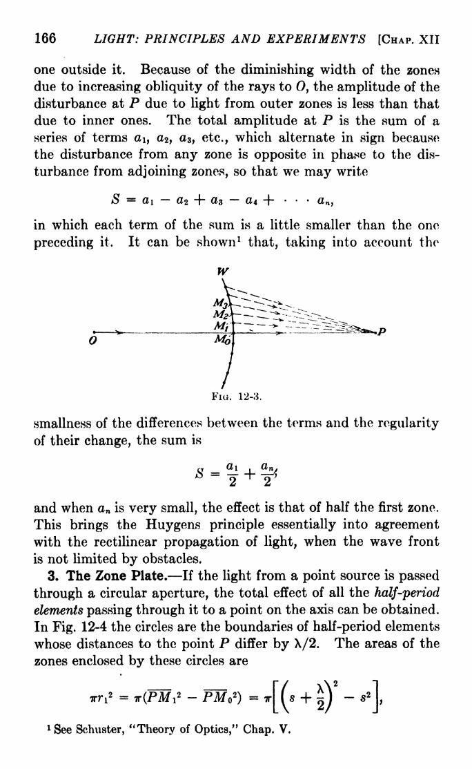
166 LIGHT: PRINCIPLES AND EXPERIMENTS [CHAP. XII
one outside it. Because of the diminishing width of the zones
due to increasing obliquity of the rays to 0, the amplitude of the
disturbance at P due to light from outer zones is less than that
due to inner ones. The total amplitude at P is the sum of a
series of terms a\, a2 ,a3 , etc., which alternate in sign because
the disturbance from any zone is opposite in phase to the dis-
turbance from adjoining zones, so that we may write
S ai a2 + a3 o 4 + an ,
in which each term of the sum is a little smaller than the one
preceding it. It can be shown 1
that, taking into account the
wV
O
IFIG. 12-8.
smallness of the differences between the terms and the regularity
of their change, the sum is
e a\ . an/6 -
2+ T
and when an is very small, the effect is that of half the first zone.
This brings the Huygens principle essentially into agreementwith the rectilinear propagation of light, when the wave front
is not limited by obstacles.
3. The Zone Plate. If the light from a point source is passed
through a circular aperture, the total effect of all the half-period
elements passing through it to a point on the axis can be obtained.
In Fig. 12-4 the circles are the boundaries of half-period elements
whose distances to the point P differ by X/2. The areas of the
zones enclosed by these circles are
!See Schuster, "Theory of Optics," Chap. V.

SEC. 12-3J D1WKAVT1UN ID/
7r(r22 - n) = 7r(PM2
2 - - J( + X)
2
etc., where s is the distance from the zone plate to the image and r
gives the radius of each circle, so that if X is small enough com-
pared to the other dimensions, X2is negligible and the area of each
zone is irsX. Consequently the consecutive zones will, becauseof the approximate equality of their obliquity, almost cancel
each other. But if alternate zones are blocked out so that theytransmit no light, the remaining ones will give an image at P. Aseries of transmitting zone apertures of this sort is called a zone
plate. If s is required to be 100 cm., for a wave-length of 0.00005
cm., the area of each zone will be about 0.0157 sq. cm.
etc.
M4
;,-M3
,MOo
FIG. 12-4.
The radii of the zone boundaries are r\ = -\Ax, r2 = \/2sX,etc., hence a zone plate may be constructed by first drawing on a
large sheet concentric circles whose radii are proportional to
the square roots of the consecutive integers 1, 2, 3, etc., and then
blackening alternate zones. This drawing can be copied photo-graphically in any desired size. The negative, or positive, thus
obtained may be used to produce an image of a distant object,such as the sun, at a distance s from the plate. Thus the smaller
the reproduction the shorter will be its"focal length." The
intensity of the image produced with a zone plate will be greaterif alternate zones are not blocked out but are left transmitting,with a phase difference of one half period introduced betweenthem and adjacent zones. This can be done with some degreeof success by covering a glass plate with a thin coating of waxwhich is then scraped away in the annular area corresponding to
alternate zones. The plate is then etched slightly with dilute

168 LIGHT: PRINCIPLES AND EXPERIMENTS [CHAP. XII
hydrofluoric acid to the proper depth. Obviously this method is
limited to the few zones which are of sufficient width to permitthe treatment. 1
4. Diffraction by a Circular Obstacle. If a circular obstacle is
hiternosed between a Doint source of light and the observer, all
JPIO. iz-o. Lsmracnon 01 iigm oy a circular oostacie. \a) snows tne origin
image point at the center of the shadow. (6) the same as (a) but with distances
so chosen that distinct circular fringes also appear in the shadow. The fringesoutside the shadow are analogous to those in Fig. 12-7. (c) the same as (a) and (6)
but with a circular obstacle 20 cm. in diameter held in the hand, and the lightcondensed by a lens so as to make the virtual distance from source to screen
equal to 7 km. (d) was taken with the monogram of the letters I and U as asource instead of a point source, (a), (6), and (c) copied from Arkadiew: Physi-kalische Zeitschrift, 14, 832, 1913. (d) copied from M. E. Hufford, PhysicalReview, 3, 241, 1914.
the light due to a number of central zones will be obstructed. Inthis case, by summing up the amplitudes due to the remainingzones in_the way^joutlinedJn.Sec..jL&8i it will be found that the
resulting disturbance is that due to one-half the first zone to
pass the edge of the obstacle. If the obstacle is not too large,
there should be on the axis at the center of the shadow of the
obstacle an image of the point source of practically the same
1 Some interesting details on the construction of zone plates are given in
Wood, "Physical Optics," Macmillan. The subject is treated more fullyin t.ho edition of 191 1 than in the later edition of 1934.

SEC. 12-3J
intensity as if the obstacle were not there. This result wasdeduced by Poisson, who considered it an argument against the
validity of FresnePs theory. Thereupon, Arago performed the
experiment, and showed that the image actually exists as pre-
dicted. The effect is illustrated in Fig. 12-5.
5. Cylindrical Wave Front. When the source is long and
narrow, as in the case of a hot filament or an illuminated slit, it
is convenient to consider the zones to be not concentric rings
but rather strips parallel to the source on a cylindrical wavefront. Let (Fig. 12-5A) represent such a source, and W a
cylindrical wave front whose axis is perpendicular to the page at
0. Then as before on either side of M points Afi, M2 , etc., maybe chosen such that the distances of the successive zones Ma
*o
Fio. 1
etc., from a point P differ by X/2. It is evident from Fig.
12-5A that the adjacent strips, which may be called half-period
zones, will differ in area rapidly at first, and then more slowly as
strips of higher number are considered. The outer ones will be
practically equal in area and their effects at P will cancel each
other, so that the amplitude at P will be due to only a few strips
about the point M o, which is known as the pole of the wave front
with respect to P.
*%&. Diffraction at a Straight Edge. Consider light from a line
source perpendicular to the page in Fig. 12-6, passing a straight-
cdged obstacle B to a screen. It is required to find the illumina-
tion at any point on the screen. Let us first consider a point P'
above P on the screen, well outside the geometrical shadow of
the obstacle. A straight line drawn from to P' intersects the
wave front at the point B', which is thus the pole of the wave
front with respect to P', and by the arguments of the precedingsection the amplitude at P' will be due only to the half-period

170 LIGHT: PRINCIPLES AND EXPERIMENTS [CHAP. XII
zones in the neighborhood of B''
. If P' is sufficiently far awayfrom P so that the obstacle imposes no limit on the elements
effectively contributing to the amplitude at P', full illumination
will exist, but if P' is a point on the screen near enough to P so
that the effective half-period zones about the pole B' are partly
obstructed, the amplitude at P' will suffer a modification depend-
ing, in the final analysis, upon whether or not there is an odd
or an even number of zones between B and B'. If the number is
even, their contribution to the amplitude at P1will be a minimum,
(a) (b)
Fia. 12-6. Diffraction at a straight edge. The source is a slit at O perpendicularto the plane of the paper.
since alternate ones are opposite in phase; if the number is odd,
the amplitude from them to P' will be a maximum, since all but
one tend to cancel each other.
As points farther and farther into the region below P arc con-
sidered, the farther will their poles lie along the wave front
below the edge of the obstacle, and the smaller will be the numberof zones contributing to the amplitude on the screen. Hence
the intensity below P will fall off gradually to zero.
For a maximum at P', BP1 - B'P' = (2n + l)X/2, and for a
minimum, BP' B'P' = 2nX/2, where n is zero or any integer.
Now if OB =a, BP =
6, and PP' =x,
BP' =, 6 2 approximately 6
OP' = v (a + 6)2 + xz = approximately a + 6 + TV
o)

SBC. 12-6]
Hence for a maximum,
DIFFRACTION 171
(2n26 2(a + 6)
or,
X =\-
a ^W
* ~\-
a-^n^
a
a mm >mum>
where n is zero or an intecror. Thus the r1iffra.rt.inn nn.t.fnm
FIG. 12-7. Photograph of diffraction at a straight edge.
be a series of maxima and minima as shown in Fig. 12-66. Aphotograph of the pattern is shown in Fig. 12-7.
6. The Cornu Spiral. The explanation of the intensity dis-
tribution observed in certain diffraction patterns of the Fresnel
type which has been presented in the preceding sections is
quite elementary, and is limited in its applicability. It serves,
however, to furnish an introduction to a much more elegantmethod of representing the disturbance at any point in a diffrac-

172 LIGHT: PRINCIPLES AND EXPERIMENTS [CHAP. XII
tion pattern. This method, due to Cornu, makes use of the
expedient of dividing the wave front into elements, which are
thereupon summed up by an extension of the vector-polygon
method introduced in Sec. 9-5.
In Sec. 12-5, in order to represent the amplitude at a point P,the wave front was considered to be divided into half-period
zones MoMi, M\M^ etc., as in Fig. 12-5A, on either side of the
pole MQ of the point P. The zone M M i was constructed bychoosing a point M \ such that the distance M\P is X/2 greater
than the distance MoP; similarly MZP is X/2 greater than M\P,
(d) (e)
FIG. 12-8. Application of the vector polygon method, (a) The sum of two
half-period zones of different amplitudes and opposite phase; (6) the sum of
two half-period zones of the same amplitude and same phase; (c) and (d) vector
polygons of eighth-period dements which together give the same as (a); (e)
vector polygon of eighth-period elements giving the same as (6) .
and so on. On the other side of the point M ,the corresponding
zones are Af MY, Mi'MJ, etc., the entire system of zones thus
being symmetrical about the point Af . If it is desired to
represent graphically by a vector polygon the amplitude at P due
to the zones M M i and JlfiAf2 ,the polygon will consist of a pair
of vectors as indicated in Fig. 12-8a. These are parallel and in
opposite directions because the phase difference between them
is TT; the vectors are not equal in length because the area of
zone AfoMi is greater than that of zone M]M2 . Similarly in
Fig. 12-86 is the vector polygon summing the amplitudes due
to the two zones Afi'Afo and AfoAfi on either side of Mo, the

SEC. 12-6] DIFFKACTION 173
resultant amplitude being given by the vector Mi Mi. It is
evident that by this method it will not be possible to represent
the amplitude due to any part of the wave front unless it con-
tains a whole number of half-period zones. Suppose, however,each zone is divided into k smaller elements, such that adjacentones differ in phase, not by fr, but by ir/k. For instance, if k is 4,
the phase difference between successive elements will be x/4, and
the vector summation of the amplitude at P due to all the ele-
ments in the zone M Mi will be that shown in Fig. 12-8c, that
Fio. 12-9. The Cornu spiral. The convolutions close up spirally to J and J'.
The distance along the curve from Mk-i to Ma corresponds to a half convolution,representing a half-period zone. The distance from to Mk-i represents twohalf-period zones opposite in phase.
for MiM* will be that in Fig. 12-8rf, and for Mi'M + MQMithat in Fig. 12-8e. Also, it is now possible to sum up the ampli-tude over fourths of zones. If the number of these small
elements in each zone is made very large, each vector will be corre-
spondingly small, and the succession of vectors representing the
elements will be a smooth curve. The curve representing all
the elements on both sides of Mo for an unobstructed wave is knownas the Cornu spiral, shown in Fig. 12-9. The entire curve is
not drawn, but the two arms are terminated in convolutions, of
which only about two are shown, which become smaller and
smaller and more nearly circular until they are finally asymptdticto circles of zero radius at J and J'. The straight line joining
J and J' and passing through the origin represents the entire

174 LIGHT: PRINCIPLES AND EXPERIMENTS [CHAP. XII
wave when it is unlimited by obstacles. Referring once more
to Fig. 12-5A, in this case the point P will receive full illumination.
Suppose, however, an obstacle is brought gradually in front of
the source from one side so that as it advances, it cuts off more
and more of the wave front. In doing so it will cut off successive
half-period zones, each of which is represented in the Cornu
spiral by a half convolution such as MkMk-i (Fig. 12-9), arid
the vector representing the summation will no longer be the line
joining J' and J, but will be a line joining J' and a point which
moves along the spiral from J toward 0. The correspondingillumination from the source will alternate between maximumand minimum. When half the wave front has been cut off, i.e.,
when the obstacle is at the pole of the point P (Fig. 12-5A), the
(b)
Fio. 12-10.
(O
total amplitude will be represented 011 the Cornu spiral by the
vector J'O.
Only two of the many graphical solutions of problems in
diffraction will be mentioned; the case of the straight edge and
the case of the single slit.
a. The Straight Edge. Actually this case has just been
described in considering an obstacle gradually brought in from
the side 86 as to obscure more and more of the wave front, exceptthat the alternations of intensity were considered as taking placeat a single point on a screen as the obstacle advanced. If,
instead, point P' in Fig. 12-6 is considered to move along the
screen toward P, then the intensity at the moving point will
alternate. On the Cornu spiral (Fig. 12-10a), a few alternations
in amplitude will be in the order J'Af3 for a maximum, J'MZ for
a minimum, J'M\ for a maximum, and thenceforth the amplitudewill diminish until J'O (Fig. 12-106) represents the amplitudeat the geometrical edge of the shadow on the straight line from

SEC. 12-6] DIFFRACTION 175
the source past the edge of the obstacle. Thenceforth the ampli-tude vector J'M (Fig. 12-10c), will reduce gradually in lengthto zero, as M moves along the curve, representing the gradually
diminishing illumination on the screen in the shadow.
FIG. 12-11.
6. The Single Slit. Consider a slit (Fig. 12-11) so narrow
that only the two central zones, one on each side of the pole of P,contribute light to P. The amplitude at P will then be given
by the vector Mi Mi (Fig. 12-12a). As points above P are
considered, the amplitude will be given by a series of vectors
(a) (b)
Fia. 12-12. Amplitudes in Fresnel diffraction at a slit.
such as Mz'Mz until when P' is reached, for which the^edge of
the slit is the pole, the amplitude is given by ON. Hence, whenthe slit width is only two zones, the center of the pattern is a maxi-
mum. Suppose, however, the slit is as wide as four zones. Thenthe amplitude at P (Fig. 12-11), is given by N'N (Fig. 12-126),
and for points just above P by M\M\ ywhich is longer than
N'N, so that in this case the intensity at the middle of the
pattern is a minimum. For cases where the aperture is smaller
than a single zone, the vector joining the two points in the spiral
is so short that it can be moved along the spiral in either direc-

176 LIGHT: PRINCIPLES AND EXPERIMENTS [CHAP. XII
tion without alternations in length, but with its greatest lengthwhen it extends equal distances on each side of 0, indicating that
th^rewill be a maximum at the middle of the pattern.
1
7. Fraunhofer and Fresnel Diffraction Compared. While it
is possible to make use of the graphical methods outlined in the
preceding sections to describe diffraction effects of the Fraun-
hofer class, the difficulties involved in a mathematical analysis
are far less than in the case of Fresnel diffraction. This is
because in Fraunhofer effects the diffracted wave is plane, mak-
ing possible a fairly simple method of summing up analytically
\\
*s
FIG. 12-13o. Fresnel diffraction through two parallel slits. While inter-
ference fringes will appear across the entire field, their visibility will he greatestat the middle point.
the disturbances reaching any point, while in the Fresnel case the
diffracted wave front is not plane.
The experimental advantages of Fraunhofer over Fresnel
diffraction are really found in those cases where the effects
to be observed are produced by the interference between two or
more beams. The diffraction is present for the reason that these
particular interference phenomena are without exception pro-
duced by apparatus belonging in class A (see Sec. 10-4) in which
a division of the wave front is made. In all apparatus such as
the grating, the echelon, and the Michelson stellar interferometer,
the elements recombined are relatively narrow sections of the
wave front from a slit source or a source of small size, and the
recombination necessary for interference is effected by focusing.
A simple experiment will serve to illustrate the point. Figures
1 For a more complete discussion of the Cornu spiral, see Meyer, "TheDiffraction of Light, X-rays, and Material Particles," University of Chicago
Press, 1934. There is also a comprehensive treatment in Preston, "Theoryof Light," 4th ed., Macmillan. See also Appendix VIII of this text.

SBC. 12-7] DIFFRACTION 177
.3
'a
g-
g
feO
oo
gcj
r fti
S= 5
us
Jl**.
^ O-
33a *
CSI

178 LIGHT: PRINCIPLES AND EXPERIMENTS [CHAP. XII
12-13o and 6 illustrate Fresnel diffraction through two slits.
Obviously the effect due to the superposition of the two diffracted
beams occurs in a region of poor illumination. It is true that by
decreasing the width of each slit the regions of greatest intensity
could be made to spread out until they overlapped, but this would
be at the expense of illumination and little would be gained. If a
lens system is used, as illustrated in Figs. 12-14a and 6, the most
intense portions of the diffraction patterns may be superposed
at the focus, and the interference fringes will be observed in the
FIG. 12-14a. Fraunhofer diffraction through two parallel slits. The visibility
of the fringe system is highest in the region of maximum intensity.
brightest part of the field. This is the advantage which the
Rayleigh refractometer has over Young's experimental apparatus
(see Sees. 10-6 and 10-8)* The two are analogous, but the
former uses Fraunhofer and the latter Fresnel diffraction. In
Young's apparatus the two slits from which the interfering
pencils of light come are so close together that it cannot be used
for comparisons of optical path.
78. Fraunhofer Diffraction by a Single Slit.1 This is illustrated
1 This is the first of a series of treatments, each of which gives the intensity
distribution in a pattern due to diffraction. In many texts it is customaryto adopt a standard method of derivation which is thereafter applied to each
case in turn. The author feels that in an intermediate course the methodsof analysis are often as valuable an acquisition for the student as an under-
standing of the phenomena themselves. Moreover, a variety of treatment
often enhances the understanding of the entire field. For this reason
different approaches have been made as often as feasible to the cases of
diffraction treated in this chapter.
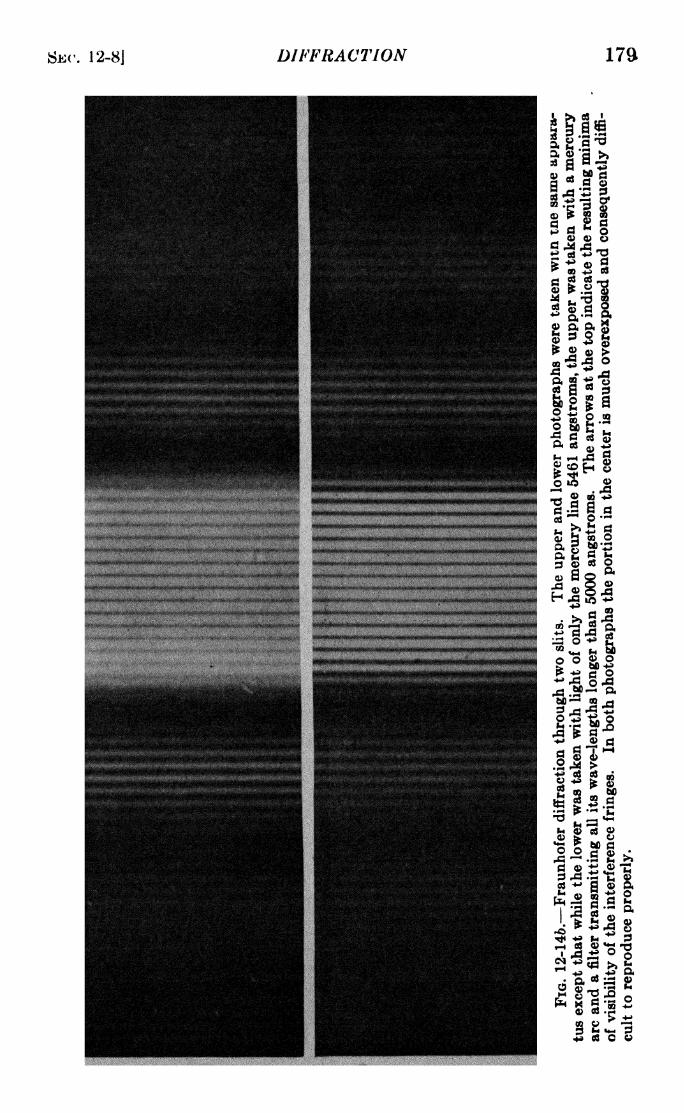
SEC. 12-8J DIFFRACTION 179

180 LIGHT: PRINCIPLES AND EXPERIMENTS [CHAP. XII
by Fig. 12-2, but to assist in the derivation, a diagram showingmore detail is desirable. In Fig. 12-15 a plane wave train of
wave-length X is incident upon a slit at an angle i to the normal
to the slit. All parts of the incident wave are in the same phaseof disturbance and can be represented by the expression
,s c sin r
Each part of the wave front passing through an element dx of
the slit will be out of phase with that passing through the middle
by an amount 2ir8/\, where 8 is the total difference of path 61 -f 52
between that part of the wave front which traverses the center
of the slit and that which traverses the element dx in passing to
the diffracted wave front. By the geometry of the figure, it
FIG. 12-15.
follows that 6 = z(sin i sin 0), where x is the distance from
the middle of the slit to the element dx and 8 is the angle of
diffraction. By convention the positive sign is used for sin 9
when the angle is as represented in the figure, and the negative
sign for diffraction. to the other side of the normal to the slit.
The disturbance in the elementary pencil of light from dx will
thus after diffraction be of the form
, ,. n \ t x (sin i + sin 0)~|, ,
.
ds' = c sin 2ir\ -~ =- \dx. (12-1)
In order to obtain the entire disturbance after diffraction, the
function of x given in eq. 12-1 may be integrated between the
limits and +:

SBC. 12-8] DIFFRACTION 181
ff = c f
+ /2
Sinfcf
i - fJ-a/2 L-* A.
(12-2)
in which for convenience ^ is substituted for the quantitysin i -f sin 0. Expanding the sine function in eq. 12-2
j/+o/2
' = c sin 2ir7p I cos* J-a/2
c cos ? sn ir-A
(12-3)
in which the second term on the right-hand side, being an even
function, is equal to zero. Hence
c sin 2ir~
sm
-o/2
Sin IT-r-
ac-~ sin<f>a
(12-4)
Thus the disturbance in the diffracted wave is of the same form
as in the incident wave but has instead of a constant amplitude c,
the amplitude
ac sin 7r(g?a/X)
which depends upon the width of the opening, the wave-length,
and the angles of diffraction and incidence. The intensity of
the resulting diffraction pattern, after the light has been brought
to a focus by a lens, is proportional to the square of the amplitude.
Considering the proportionality factor to be unity, we have from
eq. 12-4,
a 2c2 sin2
7 =
For simplicity, we may put this equal to (sin2u)/u
2 and proceed
to analyze the intensity pattern as follows :
a. When u =0, (sin u)/u is an indeterminate quantity which
evaluated gives unity. This corresponds to <p 0, the middle
of the diffraction pattern, and to i, or, in other words, to a
position directly opposite the source.

182 LIGHT: PRINCIPLES AND EXPERIMENTS [CHAP. XII
b. When u = mw, for m =1, 2, 3, etc., the intensity will be
zero, representing a series of equidistant minima on either side
of the central maximum given by case a. It should be noticed
that the distance between the two minima corresponding to
m = 4-1 and m 1 is twice the distance between any other
two adjacent minima.
c. Between the minima will exist a series of maxima whose
positions cannot be found by inspection. To locate them we mayput the first derivative of the intensity with respect to u equal
to zero.
dl _ 2 sin u
du u"-(u cos u sin u) = 0. (12-6)
The first factor on the right-hand side gives the cases (a) and (b)
already discussed. The second factor put equal to zero can be
FIG. 12-10.
written tan u = u. In order to find the values of u satisfying
this equation, we may find the values which satisfy simultane-
ously the equations y = tan u and y = u. These graphs are
shown in Fig. 12-16. The intersections of the solid lines are the
required values of u. The dashed lines parallel to the ^/-axis
give the values of u for which the angle is 7r/2, 3ir/2, 57T/2, etc.,
and the dotted lines the values corresponding to the positions
of maxima. It is apparent that the maxima do not lie midway

SEC. 12-8] DIFFRACTION 183
between the minima but are displaced somewhat toward the
middle of the pattern, the displacement being greatest for
the maximum of lowest order. The values of u for the central
maximum and the first six maxima on either side are given below,
together with the relative intensities, the intensity for the
central maximum being taken as unity.
An examination of eq. 12-5 discloses that if the slit is madenarrower the entire diffraction pattern will broaden. Since the
= -J/7 ~2/7 -ii +ii
FIG. 12-17. Graph of intensity distribution in the diffraction pattern of u
single slit.
minima occur where ira<(>/\= mir, a smaller value of a corre-
sponds, for any given value of m, to a larger value of <p, and hence
of sin 0. Increasing the angle of incidence will also result in a
broadening of the pattern, since it will diminish the effective
aperture, which is a cos i. An increase in X will also correspond
to an increase in v for both the maxima and the minima. Henco
if light of more than one wave-length be incident on the slit each
maximum except the central one will consist of a spectrum whose

184 LIGHT: PRINCIPLES AND EXPERIMENTS [CHAP. XII
violet end will be closer to the middle of the pattern than the red
and whose width will be proportional to the order of the maxi-
mum. A graph of the diffraction pattern of a single-slit openingwith monochromatic light is shown in Fig. 12-17. A photographof the diffraction pattern obtained with one slit is shown in
Fig. 12-26.
'9. Two Equal Slits. If two parallel slits are used, the resulting
disturbance after diffraction can be found analytically by the
same procedure as followed in finding that for a single slit. For
simplicity consider the two slits to be of equal width a, and
separated by an opaque space 6. Each part of the wave front
passing through an element dx in either slit will, as before, be
out of phase with that passing through the middle of the first
slit by an amount 27r5/X. Consequently eq. 12-1 gives the
disturbance ds' in each element of the diffracted wave, and to
find the disturbance in the entire diffracted wave front, the
integration over the entire wave front passing through two slits
may be performed. The total disturbance will be
, f. r . N f +o/2 , /+3a/2+6Sr
(two slits)= I ds' + I ds',V '
J-a/2 J+a/2+b'
since the distances of the boundaries of the two slits are the
limits of integration given. The result is
, n sin (ira<f>/\) TT(O + b)<p . 2irt /10 -,S = 2ac - -^
- cos r sin -7=-; (12-7)r \ /
and the intensity, given by the square of the amplitude factor,
is then
As would be expected, a comparison of eqs. 12-5 and 12-8 shows
that the intensity of the maximum for two equal openings is four
times the intensity for a single opening of the same width, the
amplitude being twice as great. Also, except for the factor 4, the
expression for the intensity is the same as that for a single slit
multiplied by the factor cos2w-^--
,which varies between
A
unity and zero for positive and negative values of <p, and hence
for positive and negative values of 0. Two important features

SBC. 12-9] DIFFRACTION 185
in the intensity pattern for two slits then follow: (1) Thedistribution of intensity due to a slit of width a, which will be a
diffraction pattern like that shown in Fig. 12-17; and (2) super-
posed upon this a series of maxima and minima whose spacing
is determined by the values of a and 6, which will be a series of
interference fringes in which the maxima are limited in intensity
by the diffraction pattern. To show the result graphically we
may first construct the graph of 4o2c2 , /x ( 9 ,and under the
2
I TT-
7i 2ir
FIG. 12-18. Graph of the intensity distribution in the diffraction and inter-
ference pattern due to two equal slits, for which 6 = 3a.
curve thus obtained, draw the graph of cos2[ir(a + b)<p/\]. By
inspection of the latter function we see that there will be a series
of minima when ir(a + b)<f>/\= (2m 4- 1)^/2, and a series of
maxima when ir(a 4- b)v/\ =mir, where m =
0, 1, 2, 3, etc., or
(12-9)
, . . x (2m -f,
v?(mmima) = -^ ,> = sin i H- sin 0,(L -f- o)
**V(maxima) = 2mX
2(o + 6)T = sin i 4- sin 6.
Hence the maxima will be evenly spaced and midway between
the minima. The intensity of a maximum for a particular value
flf m will in all cases be limited by the value of , /x ( 9 > but it"* *(ira<t>/\)
2
pend also upon the relation between b and a. If b is equalto an integer times a, there will be a value of m corresponding to
a maximum of the two slit interference pattern which will be

186 LIGHT: PRINCIPLES AND EXPERIMENTS [CHAP. XII
located at the minimum of the diffraction pattern. The graphshown in Fig. 12-18 is for the case where b = 3a.
The pattern obtained with two or more openings is an inter-
ference pattern since it is due to the superposition of separate
beams, originally from the same source, in such a manner that a
regular distribution of maxima and minima of intensity is the
result.
10. Limit of Resolution. According to Rayleigh's criterion,
the limit of resolution with a single opening is reached when the
two objects are such a distance apart that the central maximumof the diffraction pattern of one object coincides with the first
minimum of the diffraction pattern of the other. We mayconsider the two objects to be two parallel incandescent fila-
ments, or two slits close together and illuminated, or, in fact,
any two sources of light parallel to the diffracting slit. In Sec.
12-8 it was shown that the first minimum of the diffraction
pattern of a single object occurs when u =ira<f>/\
=TT, or when
V X/a. But <p= sin i + sin 0, so that for normal incidence,
and provided <p is not too large (i.e., provided a is not too small),
<p= = -
(12-10)fL
If, however, the intensity pattern is due to two slits, it follows
from eqs. 12-9 that the limit of resolution is reached when
If a has the same value in both eqs. 12-10 and 12-11, it follows
that the angular separation of two objects which are just resolved
is less than half that for a single slit, the exact ratio between the
two angular separations depending on the value of b. The
larger b is, the smaller will be the angle for the limit of resolution
with two slits and the greater will be the resolving power. If,
moreover, the a in eq. 12-11 is a', much smaller than a in eq.
12-10, and the value of a' + b is the same as that of a, the
resolving power of the two slits will be twice that of the single
opening. This condition is approximated in the case of the
stellar interferometer which will be discussed later. In the
simplest form of this instrument, the central part of a lens of
width a is covered up, permitting the light to pass only through

SEC. 12-11] DIFFRACTION 187
two narrow openings at the edge, whose separation is a' -f 6,
where a' is the width of each opening and b is the width of the
cover. In this case, a' + b is approximately equal to a.
There is a difference, however, in what is observed with one
and with two slits. If diffraction images of two objects are
obtained with a single slit, at the limit of resolution the graphical
representation of the result is that given in Fig. 12-19o. Here the
central images are so much greater in intensity than the others
that in most cases they are the principal observable features,
especially if the slit is wide. If two slits are used, at the limit of
resolution the graphical representation is that given in Fig.
ABi i
f\
(a)
O
(b)
Fig. 12-19. The difference between superposition at the Rayleigh limit in the
case of (a) diffraction by a single slit, and (6) interference by two slits.
12-196, where for each image there are several maxima not
differing much in intensity. The resulting effect of the super-
position of the two interference patterns with the separation
shown in the figure is a disappearance of the fringes. If the
superposition is not at the limit of resolution, some alternations
of intensity will be visible, the maximum visibility of the fringes
being when the dotted curve is exactly superposed on the one
represented by the solid line, but with a separation between
points A and B equal to the distance between two adjacent
maxima. The test for limit of resolution is then determined
by the degree of visibility of the fringes. This principle is madeuse of in Michelson's stellar interferometer.
11. The Stellar Interferometer. It now remains to show
that the angular separation between the diffraction (or interfer-
ence) maxima is the angular separation between the objects.

188 LIGHT: PRINCIPLES AND EXPERIMENTS [CHAP. XII
This may be done with the aid of Fig. 12-20. Points 0\ and 2
represent two very distant objects, and the straight lines con-
necting them to /i and 1 2 are the chief rays of the rays collected
by the lens which focuses the light at the image plane. The
distance between I\ and /a in the case of one opening is, for the
limit of resolution, the distance between the principal maximumof /i and the first minimum in its diffraction pattern.
In the case of two slits, the situation requires a more com-
plicated diagram. At the limit of resolution, given by the
disappearance of the interference fringes, the angle 6 is, in this
case, the angle between the two central maxima of the inter-
(a)
Middle
ofIt
X5^ Middle
(b)
FIG. 12-20. (a) Shows the relation between the angular separations of the
two objects and the two images with one slit. The lens has been omitted, (b)
Shows the corresponding case for two slits. The distance a + b is from center
to center of the slits and the distance e is from the upper slit to the inclined dottedline. There is no relation between the scales used in the two diagrams.
ference pattern, these maxima being indicated by A and B in
Fig. 12-196. The angle 0, subtended at the slit plane by the dis-
tance between the maxima A and B, is the same as that subtended
at the slit plane by the distance between the two point objects.
From Fig. 12-206
Bin B = = -4-r>a 4- 6
but by eq. 12-11,
A-2(o + 6)'
when the limit of resolution is reached. These two values of 6
will be the same when e = A/2, but since this is true when the
fringes disappear, it follows that for a separation of the two slits

SBC. 12-11] DIFFRACTION 189
such that the visibility of the fringes is a minimum as shown, the
separation s of the two objects is given by
I I i
D 2(a + b)
Similarly, the disappearance of the fringes, or, rather, the
adjustment of the separation between the slits so that the visibil-
ity of the fringes is a minimum, may be madeuse of to measure the diameters of stellar objects
whose distances are known. The application
of the principle in this case may by illustrated
by considering the case of a distant slit con-
sidered as a source. Let 1, 2, 3, 4, 5, ... n
(Fig. 12-21) represent elements in the plane of
the source parallel to its sides. For each of
these elements there will be, because of the
double slit, a pattern of equidistant maxima .
Fia '
.
12-21-~For. .
two point sourcesand minima. Patterns from elements 1, 2, the zones i, a, 3,
3 . . . n will be superposed as shown graphi- :
n each gl an!~ . r i
interference pattern
cally in Fig. 12-22. It is evident that unless the of the type iiius-
angular separation of elements 1 and n at the *rate<* m FJ8-
12:?2
by the intensity
plane of the double slit is B = A/2(a -f- 6), curves correspond-
alternations of intensity will still be observed,in ly numbered.
i.e., the visibility of the fringes will not be a minimum. If, how-
ever, the angular separation of elements 1 and n is A/2(a -f- 6),
the visibility will be a minimum, and zero in case the intensity is
uniform across the source.
An analytic treatment of the visibility of the fringes may be
based on further consideration of eq. 12-8. In this equation,
the quantity (a + b)<p is the total difference of path for light
diffracted at a particular angle 6 through the two openings, and
(a + 6)v>A is consequently the number of wave-lengths n in
that difference of path. Also, since in practice the angles i and 6
are very small, we may substitute the angles for their sines, so
that <p** i + 0. Thus for an element of the source of width di
t
considering that for small angles sin (ira^/A) =ira<p/\, we may
write eq. 12-8 in the form
- 4B2 cos2*n(i + 0) (12-12)
where B is the amplitude for a particular point in the diffraction

190 LIGHT: PRINCIPLES AND EXPERIMENTS [CHAP. XII
pattern from either opening, and n is the number of wave-
lengths difference of path. The total intensity will be
/ = f+a/2
4B* cos 2irn(6 + i)di, (12-13)J a/2
where a is the angular width of the source as seen from the posi-
tion of the double slit. Since the double slit is in front of the
objective of a telescope, a is the angular width subtended at the
telescope. If the intensity is uniform over the source, the value
FIG. 12-22. Each of the curves 1, 2, 3, ... n indicates a maximum of aninterference pattern from a line element in the source, due to two slits. Thedotted curve at the top of the picture indicates that, unless the two slits have a
suitable separation, there will be maxima and minima of intensity in the com-
posite pattern.
of B will be the same for all elements di, so that eq. 12-13 may be
written
I = 2B2F C+a/2
di + f+"/2
cos 2irnO cos 2irni diLJ-o/2 J-a/2
I
J
a
-/2sn sn di
.J
Putting
2 2/ sin 2irni di = S,)
there results
/ = p -f c cos 2irnd S sin 2irn6.
The condition for maxima and minima of intensity is
rf/
da
(12-14)
(12-15)
sn cos 2ira0)=
0,
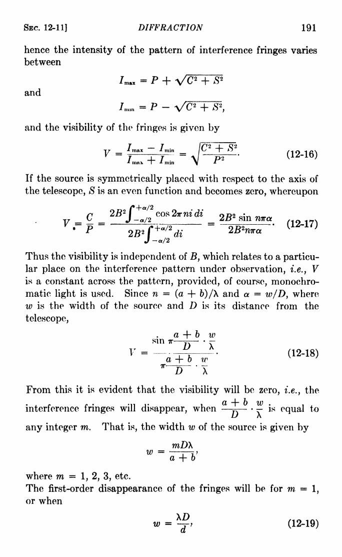
SEC. 12-11] DIFFRACTION 191
hence the intensity of the pattern of interference fringes varies
between
= P + VC2 +and
/nun = P - VC'2 + S 2
and the visibility of the fringes is given by
V ={=-=4=5
. --(12-16)
* max l" * min
If the source is symmetrically placed with respect to the axis of
the telescope, S is an even function and becomes zero, whereupon
( }
-/2
Thus the visibility is independent of B, which relates to a particu-
lar place on the interference pattern under observation, i.e., Vis a constant across the pattern, provided, of course, monochro-
matic light is used. Since n = (a -f 6)/X and a = w/D, where
w is the width of the source and D is its distance from the
telescope,
a -f b wsm
"~~lT'
XV = -f---
(12-18)a + b w ^ '
*~~D~'
X
From this it is evident that the visibility will be zero, i.e., the
interference fringes will disappear, whenj?
is equal toL) A
any integer m. That is, the width w of the source is given by
wDXW = -
j Y>a -f b
where m =1, 2, 3, etc.
The first-order disappearance of the fringes will be for m =1,
or when
w - i (12-19)

192 LIGHT: PRINCIPLES AND EXPERIMENTS [CHAP. XII
where d is the separation of the two openings in the double slit.
The disappearances of higher order will in general be moredifficult to observe, since they correspond to larger values of 6,
the separation between the two slits, for which the fringes become
very narrow.
Should the focal plane of the eyepiece not be exactly at the
focal plane of the objective of the telescope, the fringes will
still be visible, provided the relation expressed in eq. 12-19 does
not hold. In any case there is a separate diffraction patternfor each of the slits in front of the objective, and these two pat-
terns will overlap in some part of their extent. The only effect
of absence of correct focusing of the telescope eyepiece will be
that the fringes may not be observed in the most intense portion
of the field of view; they will in any case be present. Moreover,since the width of the two openings is inversely proportional to
the widths of the resulting diffraction maxima, the fringes will
still be seen (provided eq. 12-19 does not hold), even if each of
the fringes has appreciable width. If white light is used, all
of the fringes except the central one will be slightly colored at
the edges, owing to the small amount of dispersion present.
Since this dispersion is quite small, the disappearance of the
fringes, or, at least, the reduction of the visibility to a minimum,
may still be observed. In this case, the value of A in eq. 12-19
will depend on the sensitivity of the eye to color. For most
eyes the wave-length for maximum sensitivity is approximately5700 angstroms.
If the distance between two illuminated objects is to be
measured, their separation is given by
- - (12-20)
a result which may be derived by the preceding analysis.
If the source is a circular disk of uniform luminosity, a series of
strip elements on its surface will decrease in height as the edge
of the disk is approached. For this reason the angle subtended
at the telescope by the disk*must be somewhat larger than the
angle for the disappearance of the fringes. Theory shows that
in this case the diameter of the disk is given by
(,2-2!)

SBC. 12-11] DIFFRACTION 193
Similarly, in case the separation s of two stars is to be meas-
ured, it is given by
0.61XD
a (12-22)
where s is the distance between the centers of the stars. In
eqs. 12-20, 12-21, and 12-22, a is the separation between the twoslits.
Observations by this method of the diameters and separationsof celestial objects are usually made with a telescope whose
B'A 1
Fia. 12-23. The dotted circle represents the aperture of an objective; the
two heavily shaded portions represent that part of the objective through which
light passes.
central portion is covered by a shield, so that there is used only
light which passes through two narrow slots whose distance apart
can be changed. From the four preceding equations, it will bo
seen that the angular diameter of an object is proportional to
w/D, and the angular separation of two
objects to s/D. Hence the smaller these
quantities are, the larger must be the
value of a, the linear distance between
the slots, so that the measurement of A
diameters or separations of very distant
celestial objects, or those with relatively
small dimensions, would be impossible
except with a telescope objective of enormous size. For such
objects, instead of having two movable slots over the objective
as illustrated in Fig. 12-23, an arrangement of total reflection
prisms is mounted on a crossarm placed in front of the objective,
as illustrated in Fig. 12-24. While the prisms B and B' are
A'
FIG. 12-24.

194 LIGHT: PRINCIPLES AND EXPERIMENTS [CHAP. XII
primarily for the purpose of reflecting the two interfering beams
into the objective, it follows from the third condition for inter-
ference given in Sec. 10-2 that with this arrangement the fringes
are sensibly wider and hence more easily observed than if the
angle between the beams were larger.
12. Many Slits. The Diffraction Grating. If the diffraction
is by more than two equidistant slits of equal width, the equa-
tion for the disturbance after diffraction may be obtained by
integrating 12-1 between successive limits ~ to-f^' o ~^~ ^ *
o (\ K y?
-o" + &> ~o~ + 2& to "o" + 26, etc. This procedure is so long and2i i t
involved that it is likely to mask the significance of the final
result. Therefore a more descriptive method of accounting for
the resulting diffraction pattern will be used.
In the case of two slits it was shown that interference maxima
will occur at values of <f> for which the elements of disturbance
from corresponding points in the two slits have path differences
of mX, where m =0, 1, 2, 3, etc., i.e., phase differences of 2mir.
Correspondingly there will be minima for values of <f>which the
difference of path is (2m + l)X/2, and the difference of phase is
(2m H- l)ir. Let us now consider the case of three slits. Obvi-
ously maxima will occur for the same values of <p as for two slits,
i.e., where the difference of path through successive slits is mX.
These are called principal maxima. But the minima will not
occur midway between these as in the case of two slits. The
reason is that, the difference of phase between corresponding
elements of disturbance from successive slits being at the mid-
point (2m + I)TT, two of the elements will cancel each other, and
the third will give rise to a maximum. This series of maxima,
midway between the principal maxima for three slits, will not
have an intensity comparable to that of the principal maxima,
and are called secondary maxima. On either side of these
secondary maxima will occur minima at values of <p for which the
disturbances from all three slits have a phase difference such
that their sum is zero.
These results can be described graphically by an adaptation
of the vector polygon method described in Sec. 6 of this chapter.
Consider each slit to be the source of a Huygens wavelet which
has the usual characteristic of sending light in all directions, but

SBC. 12-12] DIFFRACTION 195
with a maximum intensity in the direction of the incident wave.
Thus each slit contributes an element of amplitude to the dis-
turbance in a particular part of the diffraction pattern. Foreach element e\ t
ez , e$, let amplitude vectors v\, v2 , v$ be drawn,with the angles 'between them corresponding to a difference of
phase which will be different at different points in the pattern.Then the results are as shown in Fig. 12-25. At point D of the
diffraction pattern, for instance, at which the path difference
between successive elements is X, and the phase difference 27r,
the vectors are all in the same straight line, and add up to givethe resulting amplitude of the first-order maximum. This
Central
imageSecondarymaximum
First
order
Pathdiff.
those tiff.
Amplitude AFIG. 12-25.
amplitude squared gives the intensity graphically represented
above D. Similarly, at point A the path difference between
successive elements is X/3, and the phase difference is 2ir/3, so
that the vectors form a closed polygon. This corresponds to
zero amplitude and intensity. At B, the path difference between
successive elements is X/2 and the phase difference v, hence
three such vectors give a resultant amplitude corresponding to
the disturbance due to one element. As the angle <f> increases,
the intensity diminishes, the graph of the entire pattern being
enclosed by a diffraction curve exactly as in the case of two slits.
Similar results may be obtained for more than three slits. In
Fig. 12-26 are photographs of the patterns for 1, 2, 3, 4, 5, and
6 equal and equidistant slits. These photographs were made
with gratings in which the ratio of opaque to open space was
3:1. Theory predicts that when this ratio is a whole number,
there will be missing interference maxima which will occur at
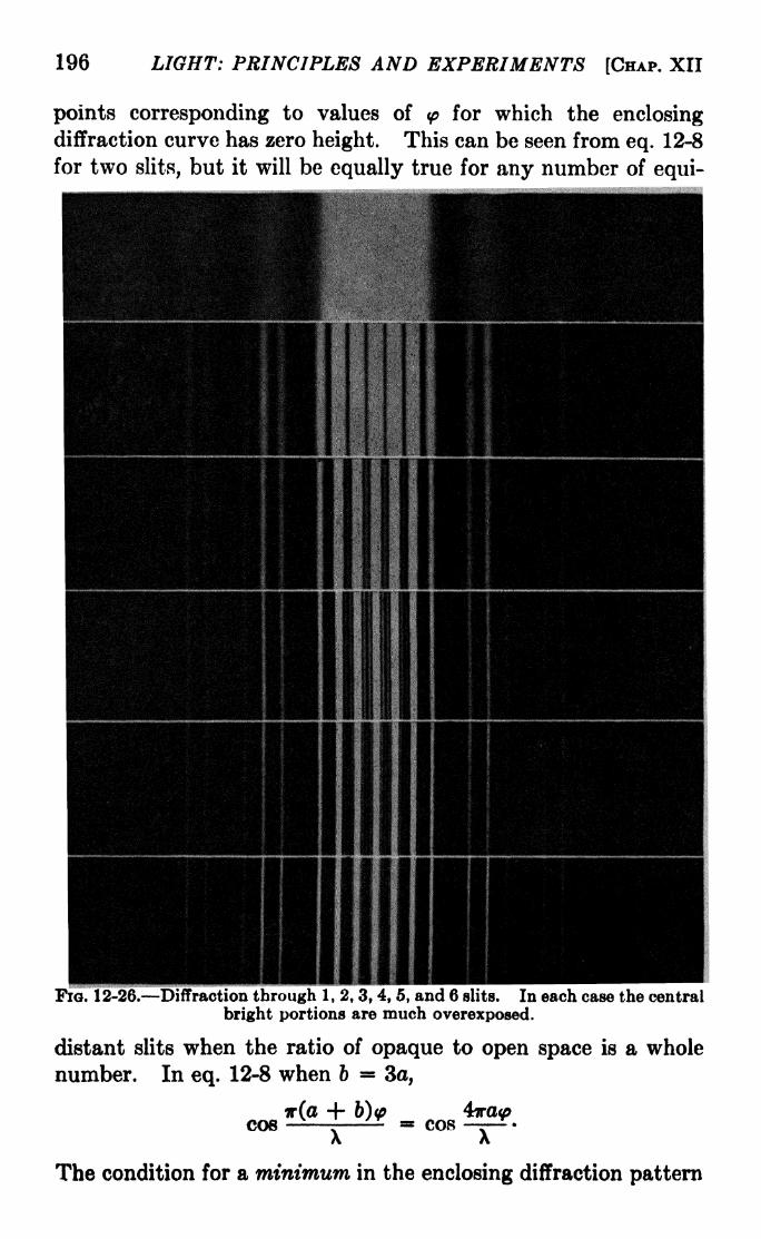
196 LIGHT: PRINCIPLES AND EXPERIMENTS [CHAP. XII
points corresponding to values of <p for which the enclosingdiffraction curve has zero height. This can be seen from eq. 12-8
for two slits, but it will be equally true for any number of equi-
FIG. 12-26. Diffraction through 1, 2, 3, 4, 5, and 6 slits. In each case the central
bright portions are much overexposed.
distant slits when the ratio of opaque to open space is a whole
number. In eq. 12-8 when 6 * 3a,
-f-COS -r- = COS
A A
The condition for a minimum in the enclosing diffraction pattern

SBC. 12-13] DIFFRACTION 197
is that va<p/\ T, but in this case cos (4^ra<f>/\) cos 47r, which
corresponds to a maximum in the interference pattern. These
orders are actually missing in the photographs. Also the num-ber of secondary maxima is N 2, where N is the number of
openings. Their intensity relative to the principal maximadecreases as N increases. This is not clearly evident in the
photographs, which were printed from the negatives so as to
suppress the principal maxima, the latter being much overexposedin the negative. The most important thing illustrated in this
series is that as N increases the principle maxima, or orders
become increasingly sharp. For very large values of Ntthe
intensities of the secondary maxima are practically zero, and
each principal maximum (with a perfect grating) is a sharp
image of the slit.
These results are for monochromatic light. If more than one
wave-length is present in the source, each order will consist of a
spectrum. Since <p m\/(a -f- 6), it is evident these the spectrawill have the blue end nearer the central image, i.e., at smaller
values of<f>,
than the red end.
Diffraction gratings in practice are made by ruling lines close
together with a diamond on polished metal or glass surfaces. In
most cases the entire surface retains its reflecting qualities, the
rulings serving merely to create a
surface with a periodic structure.
It might seem at first as if the funda-
mental concept of diffraction does
not hold in such a case, since the \/\/\ / \ /incident waves are not interrupted -\ -\' \' */
or cut off by obstacles in the form
of opaque spaces. However, the
periodicity of the reflecting surface FlQ - 12'27 *
consists of regularly spaced strips, of a width appropriate to the
wave-lengths of the diffracted light, which are as effective in
giving rise to regularly spaced elements of disturbance as in the
case of a transmission grating. This is illustrated in Fig. 12-27.
Moreover, by shaping the diamond tool with which the grating
is ruled, it is possible to send a preponderance of light into
particular orders.
13. The Dispersion of a Grating. In eq. 12-9 the position
of a maximum was given by
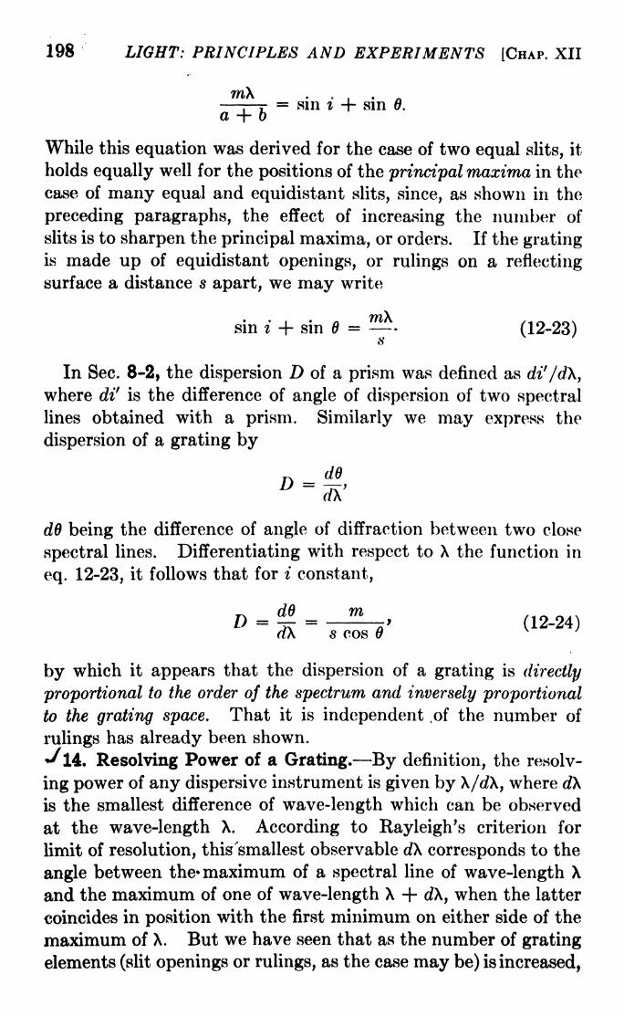
198 LIGHT: PRINCIPLES AND EXPERIMENTS [CHAP. XII
wX !/-rr = sin i + sin 6.
While this equation was derived for the case of two equal slits, it
holds equally well for the positions of the principal maxima in the
case of many equal and equidistant slits, since, as shown in the
preceding paragraphs, the effect of increasing the number of
slits is to sharpen the principal maxima, or orders. If the gratingis made up of equidistant openings, or rulings on a reflecting
surface a distance s apart, we may write
sin * + sin 9 = -
(12-23)8
In Sec. 8-2, the dispersion D of a prism was defined as di'/d\,
where di' is the difference of angle of dispersion of two spectral
lines obtained with a prism. Similarly we may express the
dispersion of a grating by
dO
d& being the difference of angle of diffraction between two close
spectral lines. Differentiating with respect to X the function in
eq. 12-23, it follows that for i constant,
D = . _ , (12-24)s cos 6
^ J
by which it appears that the dispersion of a grating is directly
proportional to the order of the spectrum and inversely proportional
to the grating space. That it is independent .of the number of
rulings has already been shown.
^14. Resolving Power of a Grating. By definition, the resolv-
ing power of any dispersive instrument is given by X/rfX, where dX
is the smallest difference of wave-length which can be observed
at the wave-length X. According to Rayleigh's criterion for
limit of resolution, this'smallest observable d\ corresponds to the
angle between the*maximum of a spectral line of wave-length X
and the maximum of one of wave-length X + d\, when the latter
coincides in position with the first minimum on either side of the
maximum of X. But we have seen that as the number of grating
elements (slit openings or rulings, as the case may be) is increased,

SEC. 12-15] DIFFRACTION 199
the maxima become narrower, and the position of the minimum oneither side of the principal maximum (a spectral line) becomescloser to the center of the maximum. For instance, in the case
of six slits the distance between one principal maximum and the
next is the same as for two slits, but the distance between each
principal maximum and the adjacent minimum is one-third
as great as for two slits. For N slits, the distance between a
principal maximum and an adjacent minimum may be seen to be
2/N times the corresponding distance for two slits, the latter
being X/2s when a + b in eq. 12-9 is replaced by s. Thus the
angle of diffraction corresponding to this distance becomes, for
N slits,
It'
^s= ^sin ^ = COS 6 d6 ' (12-25)
The resolving power may now be obtained from the relations in
eqs. 12-24 and 12-25; i.e.,
f^ A (Itr A Tfl -m r ^ -. r /-grk r%/-\R =-jr
=-jr -js
=--Q Ns cos 6 = mN . (12-26)
d\ d\ dd s cos 6^ '
Thus the resolving power of a grating is the product of the order
of interference m and the number of rulings N on the grating,
and is independent of the grating space.
The resolving power may also be obtained by applying the
general principle illustrated in Sec. 8-3, wherein it was shown that
the resolving power of a prism may be obtained by multiplying
the dispersion by the width a of the beam of light intercepted
by the prism, or, by putting R = aD. Applying this principle to
the case of the grating, for which, if w be used for the width of
the diffracted beam and I the length of the grating,
w I cos 6.
Thus,771
R = w - D = / cos 6K COS 6
in which l/s is the number of rulings on the grating, so that
R = mN.
15. The Echelon. This instrument, invented by Michelson,
is an interesting illustration of the application of the principles of

200 LIGHT: PRINCIPLES AND EXPERIMENTS [CHAP. XII
both diffraction and interference. Like the diffraction grating,it is an "interference spectrometer," belonging to class A (see
Sec. 10-4), in which there is a division of the wave front. It
consists of a pile of plane-parallel plates of equal thickness,
arranged as illustrated in Fig. 12-28, each plate projecting beyondthe one following it by a small width w. Consider a plane wavefront F, advancing toward the right. Upon reaching any one of
the surfaces such as S\tan ele-
ment of the wave front of width
w passes through air, while
another element of the same
width traverses the thickness t
of the glass plate between sur-
faces Si and S%. The diffrac-
tion pattern will be spread over
a very small area if, as in prac-
tice, w is of the order of mag-nitude of 1 mm. . At an angle
of diffraction with the normal
to the face of the glass plate the. path difference between the
light through glass and that through air is n(cd) ab. But
>-$.-
TWi_
Sj SfFIG. 12-28.
db t cos B w sin 0,
which for small angles may be written
ab = t wB.
The path difference at angle 6 is thus
(n l)t -h wO = wX,
(12-27)
(12-28)
where m is the order of interference for a single plate at angle d.
The dispersion d&/d\ obtained from eq. 12-28 is given by
WJL
w d\(12-29)
In order to express D in terms of measurable quantities, it is
desirable to eliminate m between eqs. 12-28 and 12-29. Since
is small, we may for this purpose write eq. 12-28 in the form
m s

SBC. 12-15] DIFFRACTION 201
Substituting this value ofm in eq. 12-29, we obtain
!,.[(. -D-X*]^. (WO)
The resolving power is given by the product of the total
aperture and the dispersion (see Sec. 8-3). The total aperture a
is the product of the number of plates N and the width w of each
step, so that
Nwt
For small angles, (n-
1)= md/t. Substituting this value of
(n 1) in eq. 12-31, we obtain
R = mN - Nt~ (12-32)
The second term on the right-hand side is small compared to the
first, so that to a high degree of approximation, R = mN, the
same as for the grating.
The appearance of the spectrum will, however, be totally
different from that ordinarily obtained with a grating. For,
note that the smallest difference of path obtainable is that intro-
duced by one of the plates. For small 0, m (n l)t/\, so
that if t 1 cm., X = 5 X 10~6cm., and n 1.5, then
m = 10,000. Thus the orders observed are always very high,
and since the angle of diffraction is small they will be very close
together, i.e., the orders will overlap in such a way as to makeobservations on an extended region of the spectrum impossible.
In order to avoid the overlapping of orders, auxiliary dispersion
with a prism is used to isolate a spectrum line to be examined.
The prismatic and echelon dispersions are in this case parallel,
instead of at right angles, as in the case of the Fabry-Perotinterferometer. It is customary to pass the light first through
the slit, collimator and prism of an ordinary spectrometer, and
then through the echelon, which is inserted between the prism
and the camera or telescope objective. Since the intensity is
distributed over a very narrow region, because of the small width
of the central diffraction minimum (i.e., large w), only a few
orders are seen at one time. For instance, with the dimensions
given above, a 30-plate echelon would yield only three orders of

202 LIGHT: PRINCIPLES AND EXPERIMENTS [CHAP. XII
comparable intensity, their numerical values being of the order of
magnitude of 300,000, say, 299,999, 300,000, and 300,001.Because of the extremely high order of interference possible,
the echelon is particularly useful in the analysis of fine structure
of spectral lines (see Chap. XIV).If made of glass, the echelon cannot be used to examine the
ultraviolet below 3500 angstroms. A quartz echelon will givefair transmission to 1800 angstroms. In recent years, reflection
echelons have been constructed, the steps being coated with
reflecting metal, so that the instrument may be used for veryshort wave-lengths. For regions below 2200 angstroms it is,
of course, necessary to place the entire instrument in an evacuated
chamber.
The principal drawback to the echelon is the practical diffi-
culties involved in its construction. The plates must be of glass
of highest optical quantity, if used for transmission, and their
thicknesses must be as nearly the same as it is possible to makethem. Another obvious disadvantage is that it is capable of no
modifications in dimension to suit special conditions, as are the
Michelson and the Fabry-Perot interferometers.
16. Rectangular Opening. The analytical expression for the
diffraction of a slit of width a derived in Sec. 12-8 took no account
of the length of the slit, that dimension being considered to be
so great that the resulting diffraction was negligible. If the
opening, instead of being very long, has a length comparable to
its width, the expression for the elements of disturbance after
diffraction must contain terms taking account of both directions.
Instead of eq. 12-1, we may write
ds' = c sin 27r ^ - yi~J \dx dy, (12-33)
L J
where <pi= sin ii + sin 0i, and ^2 = sin *2 + sin 2 ,
the sub-
scripts referring to the width a and length 6 of the opening. Then+a/2 / -H6/2
S' c sin 27T~
c cos 2ir^ I I sin 27rlyi~ ' yzy
Ida: di/.f J-o/2 J-6/2 \ A /
Since the integral of the sine between limits with the same value
but opposite sign is zero, we can write

SEC. 12-17] DIFFRACTION 203
Q' , inS = c sm
c cos
4 f*+<*/% (*-
41 * I* J -a/2 J-
j_r +a/2 r
TJ-a/2 J-
cos
sm
cos
sm-fc/2 X X
The second term is equal to zero, and the first is
dx dy. (12-35)
S' = abc sin 2ir
the intensity is given by
*sin sm
(12-36)
smx
sm '
x(12-37)
The resulting diffraction pattern for monochromatic light is
shown in Fig. 12-29.
Fro. 12-29. Diffraction by a rectangular opening whose height is five-thirds
its width. The brightest central image and those next to it are much over-
exposed, while of the orders, observed visually, which should complete the
rectangular lattice, only four appear in the photograph.
. Diffraction by a Circular Opening. While the resolving
power for a long slit opening of width a is given by 8 = X/a,
that for a circular opening is given by 6 = 1.22 X/a, where in
each case 6 is the angle between the center of the diffraction
pattern of a point object and the first minimum of intensity.

204 LIGHT: PRINCIPLES AND EXPERIMENTS [CHAP. XII
This can be shown in the following manner: Consider a planewave advancing in a direction normal to the plane of a circular
opening AB, of radius r (Fig. 12-30a). It is required to find the
expression for the intensity in the diffraction pattern at an angle0. The resulting diffraction will be like that obtained by a lens
which brings all rays diffracted at a common angle to a focus.
(a) (b)
Fio. 12-30. Diffraction through a circular opening, (a) Side view of openingwith wave-front advancing in a direction normal to the screen. (6) Front viewof the opening.
The disturbance at this point will be due to the addition of all
the elements over the area of the opening. The path difference
between the element ds at C and that at A will be AC sin B, and
the phase difference, 2irAC sin (0/X), so that if the disturbance at
A is S = sin (2vt/T}, after diffraction that due to an element ds at
C will be
S' - AC sin
jds.(12-38)
But light diffracted at the angle through an element ds' (Fig.
12-306) has the same path difference as regards the light from Aas has that from ds, since ds' lies on a perpendicular to the line
AB at C. Since AC r -f p cos ?. and since also the element
ds' has an area p d<p dp in polar coordinates, the disturbance from
ds' may be written

SBC. 12-17] DIFFRACTION 205
ds' = sin 2?rft r sin 6 p cos
<f> sin 0\, , ,, rt rt/xv
( ^--
x-- -
^-
rp ** (12"39)
and the total disturbance at the angle is
cos ~ cos
in which M = - and AT = t
(12-40)
The integral
of the second term, being an even function, is zero, so that
p cos <p sin , ,--dpd<p.
Lt/. / t sin 0\ (* fr .
tsin 27rf ~ r
JI I cos 2x-
(12-41)
The integration with respect to <p must be carried out in series
and that with respect to p by parts,1
giving as the final result
for the intensity:
77 - , ,- n + - + VA 4. I
2
^J -,etc.J
,
in which n = (wr/X) sin 6. The series in the brackets, which maybo denoted by ,
is convergent for all values of w, and goes through
positive and negative values alternately as n increases. Therewill accordingly be maximum values corresponding to ds/dn =
0,
and zero values when s = 0. The maxima and minima in
the resulting circular diffraction pattern, whose center will be
on the normal to the opening, are thus at positions for which
sin = nX/irr, where for given values of r and X, n/w takes the
values in the following table:
1 For the steps in the integration see Preston, "Theory of Light," 4th ed.,
Macmillan. A discussion is also to be found in Meyer, "Diffraction
of Light, X-Rays, and Material Particles," Appendix C, University of
Chicago Press.

206 LIGHT: PRINCIPLES AND EXPERIMENTS [CHAP. XII
Since n is inversely proportional to X, the minima for shorter
wave-lengths will be rings of smaller diameter. Likewise, since
n is proportional to r, the radius of the opening, the minima will
become smaller in diameter as the aperture is increased in size.
Thus the size of the ring for the first minimum of intensity will be
very small for a large telescope, and the resolving power will be
correspondingly large. The resolving power, ao.oordincr to
Fro. 12-31. Photograph of diffraction pattern obtained with a circular opening.The central image is much overexposed.
Rayleigh's criterion, is given by sin 6 = n\/irr, in which the
value W/TT= 0.61 is substituted, giving for small angles
6 = 0.61--r
Problems
1. What is the diameter of the central image, i.e., the diameter of
the first dark ring, formed on the retina of the eye, of a distant point
object? Assume the wave-length 5500 angstroms, and consider the
diameter of the exit pupil of the eye to be 2.2 mm. and its distance from
the retina to be 20 mm.2. Because of atmospheric disturbances, it is rarely true that the
diffraction pattern of a star is seen distinctly; instead, the star image
may be twice the size of the central image of the diffraction pattern

DIFFRACTION 207
predicted by theory. If this is true, how far from the center of the field
3f the 100-in. telescope will the effects of coma first become visible?
The focal length of the telescope is to be taken as 45 ft.
3. If the headlights of a car are 6 in. across and 3 ft. apart, how close
must an observer with normal eyes be to distinguish them as separate
objects?4. In making the upper half of Fig. 12-146, a yellow filter was used
which transmitted all wave-lengths greater than 5000 angstroms, a
mercury arc being used. In making the lower half, only the green line,
5461 angstroms was used. Count the number of interference fringes
between the points of minimum visibility and calculate the mean wave-
length of the additional radiations effective in making the upper half
r)f the illustration.
6. How must a grating of alternate transmitting and opaque spacesbe constructed so that every third order will be "missing"?
^6. A diffraction grating has 15 cm. of surface ruled with 10,000
rulings per centimeter. What is its resolving power? What would be
the size of a prism of glass for which B = 1.1 X 10~ 10 cm. which would
give the same resolving power at 5500 angstroms? If the mirrors of a
Fabry-Perot interferometer have a reflecting power of 80 per cent, whatmust be their separation to obtain the same resolving power as the
grating?
7. The spectrum lines formed by the concave diffraction grating are
astigmatic images of the slit. The equations for the primary and
secondary focal distances from the grating may be obtained from eqs. 0-8,
for a single surface, by putting n =1, n' =
I, and changing the signs
of s\, $2', and r. In place of the angle of refraction i' is to be used the
angle of diffraction 6. Find the values for $/, s 2 ', and the value of
the astigmatic difference s% /. Show that on the normal the length
of the astigmatic spectral lines is given by / sin i tan i, where / is the
length of the rulings 011 the grating.
8. Describe four ways of obtaining the absolute value of a wave-
length of light.
9. Describe four methods for obtaining the ratio of two wave-lengths.

CHAPTER XIII
POLARIZATION OF LIGHT
Thus far for none of the phenomena described has it been
necessary to assume that the light is a wave motion of a particularsort. The explanations given for diffraction and interference
will hold equally well for longitudinal waves, in which the oscilla-
tory motion is in the direction of propagation; for transverse
waves, in which the oscillations are at right angles to the direction
of propagation; and for waves having a composite motion like
that of surface waves in water. The phenomenon of polariza-
tion, however, requires for its explanation the hypothesis that
the vibrations are transverse.
1. Polarization by Double Refraction. Although double
refraction of light in crystalline media was observed by Bartho-
linus in 1669, the first comprehensive investigation of the phe-nomenon was made by Huygens in 1690. He observed that on
passing through a crystal of Iceland spar (calcite), light was doubly
refracted, i.e., the beam was divided into two, whose separation
depended upon the thickness and orientation of the crystal.
From certain elementary experiments he concluded that the two
rays had properties related to two planes at right angles to each
other, one of them containing the crystallographic axis. Huygensgave to the phenomenon jbhe name polarization.
The property of double refraction is possessed by all exceptcubic crystals. It is also a property of some organisms under
strain. Since Iceland spar shows the property to a marked degreeit is used extensively for experimental purposes, and offers a
convenient medium for study. {Calcite (crystallized calcium
carbonate) has planes of cleavage in three directions, forming a
rhombohedron. Each obtuse angle in each plane is 101 55'
and each acute angle 78 5'.) The form of the crystal is shown
in Fig. 13-1. At each of the opposite corners A and A' are three
equal obtuse angles. The line AC is an axis of symmetry with
respect to these three faces and its direction through the crystal
is associated with important optical properties Suppose the
208

SBC. 13-1) POLARIZATION OF LIGHT 209
crystal to Be placed .with its face A'B' on a screen with a pinholein it to admit light ffom beneath. On looking down into the
face AB not one image but two will be seen. Obviously these
are due to two beams which travel in the crystal with different
angles of refraction. More conveniently a black dot on a sheet
of white paper may be used instead of the pinhole. The followingobservations may be made:
a. No matter how the crystal is turned about an axis per-
pendicular to the paper, a line drawn through the two images of
i Side View
FIG. 18-1. Planes of cleavage and direc-
tion of optic axis of calcite.
Dot
Fi. 13-2.
the dot will be parallel to the projection of AC (Fig. 13-2) on the
surface of AB, as shown in Fig. 13-2a, in which the obtuse anglesare the same in Figs. 13-1 and 13-2. Figure 13-26 shows the
manner in which the two beams pass upward through the crystal.
6. (As the crystal is turned about a vertical axis, the imagetoward A remains stationary. This image corresponds to the
ordinary ray, for which the crystal acts like an isotropic mediumsuch as glass or water.
(IThe other image rotates about the first
as the crystal is turned, and its position is such that the ray must
be bent away from the normal in contradiction to the ordinary
law of refraction. This ray is called the extraordinary ray\
c. The dot corresponding to the ordinary ray appears closer
to the top of the crystal than that for the extraordinary ray.

210 LIGHT: PRINCIPLES AND EXPERIMENTS [CHAP. XIII
d. If the crystal is tilted up on the corner A' (Fig. 13-1), the
two dots draw together. If the two corners A and A' wereflattened and polished in planes perpendicular to AC, only one
image would be seen when viewed perpendicularly, no matter
how the crystal was rotated about AC, as if the light werein an isotropic medium. The direction AC is called the optic
axis of the crystal; it is not a particular line, but a direction
through the crystal.
e. If the crystal were to be flattened and polished in two planes
parallel to the optic axis and the dot viewed perpendicularly
through these, in general only one image would be seen as in d.
/. If two calcite crystals are placed one above the other above
the dot, and the top one rotated about a vertical axis as indicated
in Fig. 13-3a, 6, and c, the images will appear as shown.
2B,
(a) (b)
FIG. 13-3. Two crystals of calcite superposed, (a) Axes coinciding; (6) axesat an' acute angle; (c) axes opposite.
These observations may be explained as follows : ^Consider a
section through the crystal which contains both the ordinaryand extraordinary rays. It will also contain the optic axis
and will be perpendicular to the upper and lower cleavage
planes. This section is called a principal plane.1
1 In Fig. 13-4
is shown a principal plane as the plane of incidence, the line ACbeing the same direction as in Fig. 13-1 and 13-2. A parallel
beam of ordinary light passing up through the crystal from a dot
on the lower cleavage plane is divided into two beams which
travel through the crystal in different directions and with
different velocities.
JFor the ordinary ray traversing the crystal in any direction,
the Huygens wavelets will be spherical in shaped In Fig. 13-4
\]In optical mineralogy a principal section or plane is one containing the
ray and the optic axis of the mineral.^

SBC. 13-2] POLARIZATION OF LIGHT 211
these wavelets are represented by small circles, the commontangent of which will be the wave front. I The perpendicular to
the wave front is the direction of the ordinary ray. ( The extraor-
dinary ray travels through the crystal with a velocity which is the
same as that of the ordinary rayin the direction of the optic axis,
and which becomes increasingly
greater as its"direction of propa-
gation makes~larger angles with
the axis, until its maximumvelocity occurs perpendicular to
the axis. This is shown by the
variationIn the appearance of
depth of the two refracted im-
ages which is described in experi-
ment (c) above. In order to FIG. 13-4. The passage of the ordi-
nary ray through calcite.represent the propagation of the
extraordinary ray, the Huygens wavelets must be drawn as
ellipses, l as in Fig. 13-5, with the long axis perpendicular to the
optic axis of the crystal. The wave front of the extraordinary
ray will be the common tangent of the ellipses. While the wave
FIG. 13-5. The passage of the extraordinary ray through calcite.
front remains parallel to itself, the ray is not normal to it, thus
acting in a manner contradictory to the ordinary laws of refrac-
tion. If the light should be incident upon the crystal at such
an angle that its direction through the crystal is parallel
optic axis, there will be only one ray.
2. The Wave-velocity Surface. In the foregoing it is
posed (1) that the light is incident normally to the surface of the

212 LIGHT: PRINCIPLES AND EXPERIMENTS [CHAP. XIII
crystal, and (2) that the optic axis is parallel to the plane of
incidence. If (2) holds but (1) does not, the resulting refraction
is as illustrated in Fig. 13-6. Here the plane of the paper is the
plane of incidence. The optic axis is parallel to this plane, and
MN indicates the intersection with the surface of the crystal
which is perpendicular to that plane. To find the path of a
plane wave, MM', incident obliquely on the face of the crystal,
we may proceed as follows: By the usual Huygens construction,
a circle is drawn with the center at M and a radius equal to
M'N/riQ, where n is the index of refraction of the ordinary ray.
The line drawn from N tangent to this circle will be the refracted
FIG. 13-6. Optic axis not in refracting surface of crystal.
wave front for the ordinary ray, and MO drawn through the
point of tangency is the direction of the ray. Since the velocity
of the extraordinary ray is greater than that of the ordinary in
directions other than that of the axis, the Huygens construction
will be an ellipse touching the circle at the axis and having^ a
semimajor axis equal to M'N/ne. The tangent from N to this
ellipse is the extraordinary wave front, and Me drawn to the
point of tangency is the ray.
t. The laws of refraction in ordinary isotropic media were first
stated by Descartes as follows: "The incident and refracted
rays (a) are in the same plane with the normal to the surface,
(6) they lie on opposite sides of it, and (c) the sines of their inclina-
tions to it bear a constant ratio to one another." It is evident
that for the case just described (c) is not obeyed, for the ratio of
the sines of the angles for the extraordinary ray will vary with the
angle of incidence./ If the optic axis is not in the plane of inci-
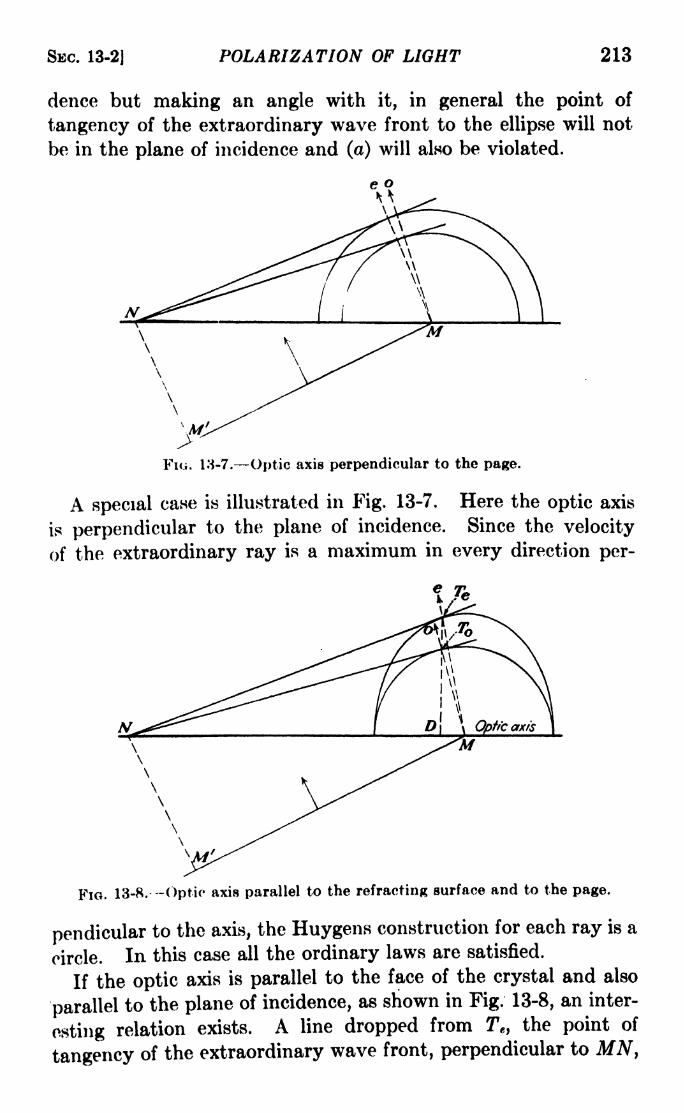
SBC. 13-2J POLARIZATION OF LIGHT 213
dence but making an angle with it, in general the point of
tangency of the extraordinary wave front to the ellipse will not
be in the plane of incidence and (a) will also be violated.
Fiu. 18-7. Optic axis perpendicular to the page.
A special case is illustrated in Fig. 13-7. Here the optic axis
is perpendicular to the plane of incidence. Since the velocity
of the extraordinary ray is a maximum in every direction per-
FIG. 13-8.- -Optic axis parallel to the refracting surface and to the page.
pendicular to the axis, the Huygens construction for each ray is a
circle. In this case all the ordinary laws are satisfied.
If the optic axis is parallel to the face of the crystal and also
parallel to the plane of incidence, as shown in Fig. 13-8, an inter-
esting relation exists. A line dropped from Te ,the point of
tangency of the extraordinary wave front, perpendicular to MN,

214 LIGHT: PRINCIPLES AND EXPERIMENTS [CHAP. XIII
will pass through To, since the polar1 of any point such as N on
the chord of contact of a circle and an ellipse is the same for both
curves. When an ellipse is projected into a circle, the ratio of two
lines such as TeD and T D is the same as the ratio of the semi-
major to the semiminor axis; hence it follows that
tanr = TfDtan re TQD n
(13-1)
where ne is understood to correspond to the maximum velocity
of the extraordinary ray through the crystal. This relation and
FIG. 13-9.
others which may be found by similar constructions have been
experimentally verified, supporting the assumption that the
surface of the Huygens wavelet for the extraordinary ray is an
ellipsoid of revolution formed by revolving an ellipse about its
minor axis, which is parallel to the optic axis.
I Of great assistance to an understanding of the manner in
which the two rays traverse the crystal is a model of the wave-
velocity surface. In the case of calcite this will consist of a sphere
inside an ellipsoid and tangent to it at the extremities of the
minor axis./ A very satisfactory model, illustrated in Fig. 13-9,

SEC. 13-4| POLARIZATION OF LIGHT 215
may be made of three pieces of cardboard, one circular, the other
two elliptical, fitted together at right angles. On these may be
indicated by circles or colored areas the wave-velocity surface
of the ordinary ray. The model represents, of course, the dis-
tances traversed in a given time by the light from a point source
inside the crystalline medium.3. Positive and Negative Crystals. Uniaxial Crystals.
Caicite is one of a group of crystals which possess a single direc-
tion in which the wave-velocity surfaces are tangent to one
another.l These are called uniaxial crystals.1* \ Crystals in which
the common tangent to the two wave fronts corresponds to morethan one direction through the crystal are called biaxial,n Uni-
axial crystals may be further divided into two groups, dependingon whether the velocity of the extraordinary ray is greater or
smaller than that of the ordinary. Caicite belongs to the former
class and is called a negative crystal, while those of the latter are
called positive. \ \ The most useful positive uniaxial crystal is
quartz,| since it occurs in abundance in many places, is hard, and
transmits a considerable portion of the near ultraviolet in the
spectrum. I The wave model for a positive crystal will consist
of a sphere outside an ellipsoid of revolution about the major p.xis
of the ellipse, which would be equal to the diameter of the sphereA
The indices for a partial list of positive and negative crystals
are given in Table II at the end of the book.
\In addition to the property of double refraction, some crystals
also absorb the two rays unequally. In tourmaline, an aluminous
silicate of boron containing sodium, magnesium, or iron, one of
them is absorbed completely, so that if two plj^es are ^ut from
it with their faces parallel to the optic a*^ .,. ^pncrossed, extinguish the light completely. Recently some success
has been achieved in the preparation of crystals of quinine-iodine
sulphate in thin sheets of transparent material. These have
properties similar to those of tourmaline, so that pieces cut from
the same sheet and crovssed may be used with considerable success
in experiments in polarized light. This material, called polaroid,
is also useful for the reduction of glare due to light reflected from
polished surfaces, since such light is often polarized^
4. Polarization by Reflection. In 1808 Malus discovered that
after reflection fron^the surface of a transparent substance such
as glass the light exhibited the same properties of polarization

216 LIGHT: PRINCIPLES AND EXPERIMENTS [CHAP. XIII
as* the separate beams transmitted through doubly refracting
crystals. This can be demonstrated in the following way: Froma source (Fig. 13-10a) allow a beam of light to pass through a
horizontal slot about 5 mm. high to a clean glass plate Pi at an
angle of incidence of about 57 deg. Above Pi place another glass
plate P2 which can be rotated about a vertical axis. It is con-
venient to exclude light from other sources by laying beneath Pia piece of black cloth or paper. If possible. P2 should be made of
black glass, but if this is not available, a backing of black paper
may be gummed to it, or it may be coated on the back with
optical blacky On looking into P2 from the position indicated in
f
i
- Pile of
\ plates
FKJ. 13-10.
Fig. 13-10a, no great change in intensity will be observed in the
light from S as P2 is rotated about a horizontal axis, but if it is
turned through 90 deg. about a vertical axis, it will be found that
afterward a rotation about a horizontal axis will cause the light
to. chan*^ ;" intensity. When the angle of P2 is such that the
pj' .V AAsiice upon it is at right angles to the plane of inci-
dence upon Pj, and the angle of incidence of the ray upon P2 is
about 57 deg., the light from S will be extinguished. The angle
of incidence upon either mirror is then called the polarizing angle.
This experiment can be explained by certain assumptions as to
the nature of the light and the effect upon it of reflection at the
two mirrors. Let us suppose that the light is a transverse wave
motion, composed of vibrations in all possible orientations in
planes perpendicular to the direction of propagation. Then
these vibrations may be resolved into two sets of components
perpendicular to each other, as shown in Fig. 13-11, in which the
short bars crossing the rays represent components of vibration
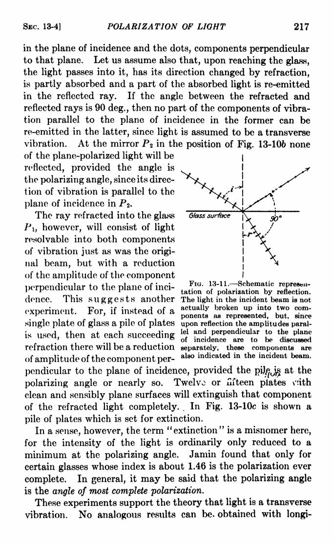
SEC. 13-4] POLARIZATION OF LIGHT 217
in the plane of incidence and the dots, components perpendicularto that plane. Let us assume also that, upon reaching the glass,
the light passes into it, has its direction changed by refraction,
is partly absorbed and a part of the absorbed light is re-emitted
in the reflected ray. If the angle between the refracted andreflected rays is 90 deg., then no part of the components of vibra-
tion parallel to the plane of incidence in the former can be
re-emitted in the latter, since light is assumed to be a transverse
vibration. At the mirror P* in the position of Fig. 13-106 noneof the plane-polarized light will be
reflected, provided the angle is
the polarizing angle, since its direc-
tion of vibration is parallel to the
plane of incidence in Pa.
The ray refracted into the glass
P\ t however, will consist of light
resolvable into both componentsof vibration just as was the origi-
nal beam, but with a reduction
of the amplitude of the component
perpendicular to the plane of inci-, J
10 ' i3-ii.-^hematic* r i tation of polarization by reflection.
donee. This suggests another The light in the incident beam is not
experiment. For, if instead of a actual|
y broken up;n
,
to *w cPm'
K ' ponents as represented, but, since
single plate of glaS a pile of plates upon reflection the amplitudes paral-
thpn at pap lel and Perpendicular to the planeL11CI1. rtl/ VjCtCl , . . , j i i- i
_of incidence are to be discussed
refraction there will be a reduction separately, these components are
of amplitude of the component per-also &t** in incident beam.
pendicular to the plane of incidence, provided thepU/pJ^
a
polarizing angle or nearly so. Twelvo or nfteen plates \*rith
clean and sensibly plane surfaces will extinguish that componentof the refracted light completely. .
In Fig. 13-10c is shown a
pile of plates which is set for extinction.
In a sense, however, the term "extinction" is a misnomer here,
for the intensity of the light is ordinarily only reduced to a
minimum at the polarizing angle. Jamin found that only for
certain glasses whose index is about 1.46 is the polarization ever
complete. In general, it may be said that the polarizing angle
is the angle of most complete polarization.
These experiments support the theory that light is a transverse
vibration. No analogous results can be. obtained with longi-

218 LIGHT: PRINCIPLES AND EXPERIMENTS [CHAP. XIII
tudinal sound waves. The hypothesis which has been introduced
concerning the nature of the mechanism of reflection has been
found by other experiments to be sound and is supported byaccepted theories of the nature of light.
6. Brewster's Law. It is evident that if the mirror Pi (Fig.
13-106) is set at angles other than the angle of polarization, the
reflected beam will contain a considerable proportion of light
whose direction of vibration contains a component parallel
to the plane of incidence. At the polarizing angle, this is reduced
to a minimum, and the reflected and refracted rays are per-
pendicular to each other. Then Snell's law becomes
n = sin sin i
sin r sin (90 i)
= tan i. (13-2)
This result is known as Brewster's law, after its discoverer.
The polarizing angle thus depends upon the transparent sub-
stance used, and to a small extent upon the wave-length of the
light. The polarizing angles for the orange and blue for two
representative kinds of glass are given below:
For ^.toueu metallic surfaces Brewster's law does not hold,
although some degree of polarization occurs upon reflection.
6. Direction of Vibration in Crystals. We are now, in a posi-
tion to determine the direction of vibration of the two rays in
calcite. Let P\ (Fig. 13-10a) be placed at the polarizing angle
and in place of Pz be placed a section of calcite split along cleavage
planes, with a dot of ink on its lower surface. It will be observed
that when the calcite is held with the cleavage faces horizontal
and is turned about a vertical axis, there is a position where the
ordinary ray disappears. This will be when the principal section
of the crystal, containing the optic axis, is perpendicular to the
plane of incidence. If the crystal is turned through an angle of
90 deg. the extraordinary ray disappears. Because of some

SBC. 13-7] POLARIZATION OF LIGHT 219
inaccuracy in adjustment of the apparatus the disappearance in
either case may not be complete, but the reduction to almost zero
intensity will be evident. From this experiment it is clear that
the ordinary ray corresponds to a vibration in a plane perpendicu-lar to the principal section, while the extraordinary ray correspondsto a vibration in the principal section. At an angle of the crystal
about halfway between the two positions the dots will be approxi-
mately of equal intensity. This experiment throws additional
light upon the experiment (e) in the first section in this chapter,where the number and intensity of the images changed as one
crystal was rotated above another.
7. Plane of Polarization. From his observations on double
refraction in calcite Huygens concluded that the ordinary and
extraordinary rays must in some way be related to the principal
plane and the optic axis. He differentiated between the two
rays by postulating that the ordinary ray was polarized in the
principal plane and the extraordinary perpendicular to it. Theexistence of these so-called planes of polarization is substantiated
by further consideration of polarization by reflection. In
Sec. 13-4 it was pointed out that only when the two mirrors P t
and PZ (Fig. 13-10a) are arranged so that the planes of incidence
and reflection at both mirrors coincide is the light which reaches
the eye a maximum in intensity. This may be interpreted in
the form of a conventional statement that the plane of incidence
thus described is the plane of polarization of the reflected light.
Actually, however, from the results of experiments, some of
which have been outlined in the preceding paragraphs, it appearsthat the direction of vibration in every case is perpendicular to
this plane of polarization. The original phraseology of Huygensstill persists in treatises on the subject, and plane of polarization
is still referred to, rather than plane of vibration] in fact, fre-
quently both terms are used. There seems to be no reason for
using both terms in an elementary discussion of the phenomenaof polarization of light. This text will avoid further description
of the phenomena in terms of the plane of polarization and will
continue to refer to the direction of vibration of polarized beams.
It is not denied that something of importance may be taking
place in directions other than the direction of vibration;whatever
it may be, however, does not come within the scope of the present
discussion.

220 LIGHT: PRINCIPLES AND EXPERIMENTS [CHAP. XIII
8. The Cosine-square Law of Maltis. When Pi (Fig. 13-10a)
is set at the polarizing angle, a ray of ordinary light incident
upon it and the polarized ray reflected from it define the plane of
reflection at the mirror. If P2 is also set at the polarizing angle
so that the plane of reflection from it is at right angles to that from
Pi, extinction will take place. For positions of the two mirrors
in which their respective planes of reflection are not at right
angles, the light will be partly reflected. (These facts were
summed up by Malus in the statement that with the two mirrors
set at the polarizing angle the intensity of the twice reflected
beam varies as the square of the cosine of the angle between
the planes ofreflection^
For instance, if Pi and P2 have the
positions shown in Fig. 13-10a, the intensity is 7, but if P 2 is
oriented to a position making an angle intermediate between
those shown in Fig. 13-10a and 6, say, 60 deg. from that in a,
then the intensity of the light reflected from P 2 is
/' = / cos2 60 = 7/4.
At the position shown in Fig. 13-106, I' = 0.
9. The Nicol Prism. As a device for producing or examining
plane-polarized light, the glass plate used at the polarizing angle is
lacking in convenience. Also, to obtain plane polarization over
any considerable area it is necessary to collimate the light.
It is usual to employ some prism of double-refracting crystal
arranged so that light vibrations in only one plane are trans-
mitted. One of the most convenient prisms is the nicol, namedafter William Nicol, who first described its construction in 1828.
The original form was made of a rhombohedron of calcite about
three times as long as it was wide. As shown in Fig. 13-12a,
this is cut along a plane perpendicular to the shorter diagonal
of the end face, which is diamond-shaped. The two pieces are
then cemented together again with Canada balsam, which has an
index of refraction intermediate between n and ne for calcite.
Since the natural angle of the end faces is slightly altered, light
incident upon the nicol parallel to the long sides will be refracted
so that the extraordinary ray is incident upon the interface at an
angle less than the critical angle of refraction, and will thus be
transmitted with no appreciable loss of intensity, while the
ordinary ray is incident at an angle greater than the critical
angle of refraction and so is totally reflected. The direction of

SEC. 13-10] POLARIZATION OF LIGHT 221
vibration of the transmitted extraordinary ray is in the plane
containing the ray and the short diagonal of the end face, as
illustrated in Fig. 13-126. Nicol prisms are often made in other
shapes, to admit beams of wider angle or greater cross-sectional
area, but the effect is the same, i.e., to transmit light with vibra-
tions in only one plane. It is usual in examinations of polarized
light to make use of two nicols. The one nearer the source,
(a)
AB
(b)
FIG. 13-12. The Nicol prism, (a) Principal section; (6) side view; (c) end view,
the arrow showing the direction of vibration of the transmitted light.
called the polarizer, is for the purpose of producing the plane-
polarized beam; the other, nearer the eye, called the analyzer, is
for the purpose of examining the state of polarization of the
transmitted light.
10. Double Image Prisms. The Wollaston Prism. While
the nicol transmits light vibrations in a, single plane and eliminates
the vibrations perpendicular to that! plane by total reflection,
it is sometimes necessary to retain both components so that the
two separate images, polarized perpendicularly to each other,
are in the field of view. This can be done for objects with

222 LIGHT: PRINCIPLES AND EXPERIMENTS [CHAP. XIII
limited area by the use of an ordinary crystal of calcite, but with
the disadvantage that the emerging beams are parallel andcannot be easily separated to any greater extent. There are
several polarizing devices which will give two diverging beams,
tjie vmost useful probably being the Wollaston prism. Its con-
struction and use are illustrated in Fig. 13-13. The light is
incident normally on a compound prism of quartz with parallel
faces made of two prisms cemented together, whose optic axes
are perpendicular to the direction of propagation but also per-
pendicular to each other. The ordinary and extraordinarybeams will thus traverse the first prism in the same direction
but with different velocities. Since the second prism is cut with
its optic axis perpendicular to that of the first, the ordinarybeam in the first prism will become the extraordinary in the
second, and vice versa. At the interface between the two prisms,
t
the beam traveling faster in the
first than in the second has an
angle of refraction which is smaller
than the angle of incidence. Like-
wise, the beam which travels
slower in the first prism than in
the second has an angle of refrac-
tion which is larger than its angleof incidence. The interface is cut
FIG. 13-13.- The Wollaston prism,at such an angle that the two plane-
polarized beams traversing the
second prism are equally inclined to the emergent face. Thuseach beam will undergo the same amount of bending by refrac-
tion, and the two will emerge into the air at the same angle to
the normal but oppositely inclined. The larger the distance from
the prism, the farther apart will be the two images.
If to a Wollaston prism is added a nicol used as an analyzer,
the combination is known as a Cornu polariscope. The nicol
may be rotated to an angle such that the two plane-polarized
images are transmitted with the same intensity, in which case the
ratio of the intensities incident upon the nicol is proportional to
the square of the tangent of the angle. The Cornu polariscope
is a useful device for the detection of small amounts of polariza-
tion, since a small change of angle of the nicol results in a large
change of the relative intensities of the two images.

SEC. 13-11] POLARIZATION OF LIGHT 223
( 11. Elliptically Polarized Light. Wave Plates. Suppose abeam of plane-polarized light is incident, as in Fig. 13-14a,
upon a thin section of crystal whose faces are parallel to each
other. For convenience suppose also that the optic axis is
parallel to the faces but makes an angle a with the plane of
vibration of the incident beam. Then the original vibration
will be divided in the crystal into two components as illustrated in
Fig. 13-146. The component of vibration parallel to the axis
(extraordinary ray) will have an amplitude A cos a, and that
perpendicular (ordinary ray), an amplitude A sin a, where Ais the amplitude of the incident vibration. If the plate is thin
and the source of appreciable area, there will be no detectable
M-f
rr '/
I/ *' e7
/
\_
(a) (b) (c)
FIG. 13-14. The heavy arrow in (ft) indicates the original plane of vibration of
a plane-polarized beam, and in (c) the plane of vibration after passing througha half-wave plate.
separation between the two beams, but since their velocities
are not the same, they will emerge from the crystal with a differ-
ence in phase. If the retardation of phase (of the ordinary in a
negative crystal, the extraordinary in a positive) corresponds to
an even number of half wave-lengths difference of path, the plane
of vibration of the emergent beam will be the same as that of the
incident beam. If the retardation corresponds to an odd numberof half wave-lengths, the two components will after emergencehave the relative positions shown in Fig. 13-14c, and their com-
bined effect will be that of a plane vibration in a plane making an
angle 2a with that of the incident beam. A plate which thus
effects a turn of the plane of vibration of the light is called a
half-wave plate. If the angle a is 45 deg., the emergent vibration
will be in a plane at right angles to the incident plane-polarized
beam.
If the retardation corresponds to an odd number of quarter
wave-lengths, the emergent components will combine to form,

224 LIGHT: PRINCIPLES AND EXPERIMENTS (CHAP. XIII
not a plane vibration, but one which in general is elliptical in foim.
An analogue is the motion of a particle which executes an ellip-
tical motion in a plane which is moved normal to its surface.
If in addition the angle a is 45 deg., circularly polarized light
results. A plate of crystal which produces these results is called
a quarter-wave plate.
The effect upon the passage of plane-polarized light throughthin crystals can be best treated analytically. Let OP (Fig.
13-15) represent the amplitude and direction of vibration of a
plane-polarized beam traveling perpendicular to the page, and
OX the direction of the optic axis of a double-refracting crystal,
of which the plane cutting OXperpendicular to the page is a
principal section. In the crystal
the incident vibration will be sepa-
rated into two, one parallel, the
other perpendicular, to the prin-
cipal section. After passageFIO. 13-15.
through a crystal whose thick-
ness is such that a path difference of 6 is introduced between the
ordinary and extraordinary rays, the amplitude of the X- and
F-components is given by
n t
x = a cos2ir-fp>
/ 8\y = o cos
2ir[ 7= + -)V V
(13-3)
If these two equations are combined so as to eliminate t, the
result will be 1
z2
2/^ _ 2xy cos (2
tf"*" P ^~
= sin 2
=p, (13-4)A
which is the equation of an ellipse, representing in general the
character of the vibration aft6r emergence from the crystal.
This ellipse may be inscribed in a rectangle whose sides are 2a
and 26, the ratio of the sides depending on the angle a between
the ^original plane of vibration and the principal section OA.
1 This may be done by solving the first equation for cos 2irt/T, expandingthe second and solving it for sin 2vt/T; squaring and adding, makingsuitable substitutions.

SBC. 13-11) POLARIZATION OF LIGHT 225
The particular character of the transmitted light will dependupon the values of 6 and a.
Case 1. 8 wX, n =0, 1, 2, 3, etc., eq. 13-4 becomes
*- -\- 0.
a o
The emergent light is plane-polarized, the vibrations being in the
same direction as in the original beam.
Case 2. 5 = (2n + l)X/2, n =0, 1, 2, 3, etc., eq. 13-4
X 11
becomes hj-
0. The emergent light is plane-polarizedG& (/
in a direction making an angle 2a with the original beam. The
original beam is in the first and third quadrants, the emergent is
in the second and fourth quadrants. If a 45, the vibrations
5X
(b)
Flo. 13-16. In (a) the angle a is w/4; in (/>) it is leHs than w/4.
in the emergent beam will be in a plane perpendicular to those in
the incident beam.
Case 3. 8 = (2n + l)A/4, n =0, 1, 2, 3, etc., eq. 13-4
x^ y^becomes -5 + j-$
= 1. The emergent beam is ellipticallyCL c/
polarized with the axes of the ellipse parallel and perpendicular,
respectively, to the principal section of the crystal. If a = 45,a = b and 2
-f- 2/2 = a 2
,and the emergent light is circularly
polarized. For 5 = A/4 the vibration corresponds to the motion
of a particle moving in a clockwise direction in a circle of radius
a; for 5 = 3A/4 the circular vibration will be in the opposite sense,
i.e., counterclockwise.
Case 4. If 5 is other than an integral multiple of X/4, and
therefore does not come under one of the three cases above, the
light will in general be elliptically polarized.
For a =7T/4, these results may be represented graphically as
in Fig. 13-16a. The straight line on the left represents the plane
of the emergent vibration for a plat^bf thickness zero, or the

226 LIGHT: PRINCIPLES AND EXPERIMENTS [CHAP. XIII
plane of vibration of the incident beam. The others represent
the effect on the state of polarization of the emergent light by
passage through such crystal thicknesses as to introduce addi-
tional path differences of A/8. The arrows indicate the direction
of rotation in the cases of circular and elliptical polarization.
If the angle a is less than 45 deg., the resulting vibrations will
be as in Fig. 13-166. If a is greater than 45 deg., the effect will
be to increase the vertical axis instead of diminishing it.
It will be noticed that except for a = or ?r/2 it is possible to
produce elliptically polarized light with wave plates which
introduce a retardation of an odd number of quarter wave-
lengths, the difference between this case and case 4 above beingthat with the quarter-wave plate the axes of the ellipse are parallel
and perpendicular to the principal section of the crystal. It
should also be noticed that it is impossible to obtain circularly
polarized light with a quarter-wave plate unless the angle
between the optic axis and the plane of vibration of the incident
light is 45 deg.)'
In practice it is customary to make quarter-wave plates and
half-wave plates of mica. Although mica is not uniaxial but
biaxial, in some kinds the angle between the two axes is small.
Mica vsplits easily along planes of cleavage which are perpendic-
ular to the bisector of the angle made by the optic axes. Because
of the strains introduced when it is made into thin sheets, cello-
phane is also anisotropic, and may be used for making quarter-
wave plates by superposing two pieces at a suitable angle.
In the preparation of wave plates it is customary to mark with
an arrow the plane of vibration of the slower component through
the crystal; if the plate is made of calcite or some other uniaxial
negative crystal, this is also perpendicular to the direction of the
optic axis. In mica, it indicates only the plane of vibration of the
slower component, or the principal section in which that com-
ponent vibrates.
( 12. The Babinet Compensator. In the production or analysis
of elliptically polarized light the quarter-wave plate is limited to
a narrow band of wave-lengths. There are several devices which
do not have this limitation, the compensator of Babinet being
the most useful. As illustrated in Fig. 13-17, it is made of two
wedges of quartz with their optic axes perpendicular to each
other, and both perpendicular to the direction of propagation of
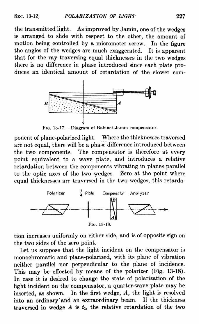
SBC. 13-12] POLARIZATION OF LIGHT 227
the transmitted light. As improved by Jamin, one of the wedgesis arranged to slide with respect to the other, the amount of
motion being controlled by a micrometer screw. In the figure
the angles of the wedges are much exaggerated. It is apparentthat for the ray traversing equal thicknesses in the two wedgesthere is no difference in phase introduced since each plate pro-duces an identical amount of retardation of the slower com-
FIG. 13-17. Diagram of Babinet-Jamin compensator.
ponent of plane-polarized light. Where the thicknesses traversed
are not equal, there will be a phase difference introduced between
the two components. The compensator is therefore at every
point equivalent to a wave plate, and introduces a relative
retardation between the components vibrating in planes parallel
to the optic axes of the two wedges. Zero at the point where
equal thicknesses are traversed in the two wedges, this retarda-
Polciriier Compensator Analyzer
Fio. 13-18.
tion increases uniformly on either side, and is of opposite sign on
the two sides of the zero point.
Let us suppose that the light incident on the compensator is
monochromatic and plane-polarized, with its plane of vibration
neither parallel nor perpendicular to the plane of incidence.
This may be effected by means of the polarizer (Fig. 13-18).
In case it is desired to change the state of polarization of the
light incident on the compensator, a quarter-wave plate may be
inserted, as shown. In the first wedge, A, the light is resolved
into an ordinary 'and an extraordinary beam. If the thickness
traversed in wedge A is t\ t the relative retardation of the two

228 LIGHT: PRINCIPLES AND EXPERIMENTS [CHAP. XIII
beams is t\(ne no), while for thickness k traversed in wedge Bthe relative retardation is h(ne nQ). The total retardation
will be
e- n ). (13-5)
For the light traversing equal thicknesses of A and B, 8 = 0.
At distances from this middle position having retardations
X, 2X, 3X, etc., the light is plane-polarized and vibrating parallel
to the original plane, as at the middle position. At positions
midway between these, where the retardation is X/2, 3X/2, 5X/2,
etc., the transmitted light is plane-polarized but vibrating in a
plane making an angle 20 with the original plane of vibration,
Center
iFio. 13-19. Polarizations due to a Babinet compensator with its axes at
45 deg. to the direction of vibration of an incident plane-polarized beam. Thefringe pattern (d) really has an intensity distribution similar to that of double-beam interference fringes and only the positions of the minima are indicated.
where B is the angle between that plane and the direction of the
optic axis in the first wedge. Thus there is a set of equidistant
positions at which the light is plane-polarized, and in any adjacent
pair of such positions the planes of vibration are parallel to,
and at an. angle of 26 to, the original plane of vibration. At all
other positions the light will in general be elliptically polarized.
If B = 45, the alternate plane-polarized beams transmitted
by the compensator will consist of vibrations at right angles to
each other. Midway between these the retardation will be like
that of a quarter-wave plate with its principal section at 45 deg.
to the plane of vibration of the incident light, and the'transmitted
light will be circularly polarized. At other positions, the retarda-
tion will be that of a fractional-wave plate producing elliptically
polarized light. This situation is illustrated in Fig. 13-19a, in
which the arrows on the circles and ellipses represent the direction
of rotation introduced. If the field of the compensator now be

SEC. 13-12] POLARIZATION OF LIGHT 229
viewed through a nicol (analyzer) set so as to extinguish the light
transmitted at the middle position, there will be seen a set of dark
fringes crossing the field perpendicular to the long edge of the
compensator. These are indicated in Fig. 13-19d Only the
central fringe will be black if white light is used; the others will
be colored. If 9 7* 45, the fringes will be dark, but not black,
with monochromatic light. The distance apart of the fringes
will correspond to phase differences of 2ir, or path differences of X.
If the analyzer is rotated- through 45 deg., these fringes will
disappear and the entire field will become uniform in intensity,
since the analyzer will have no effect at the positions of circular
Flo. 13-20.
polarization, and at all other positions will effect a retardation
changing plane or elliptical vibrations to circular ones.
It is thus evident that the compensator will in general transmit
elliptically polarized light for which the ellipticity will depend
upon the 8 in eq. 13-5 and which will, for 6 = 45 and also
for certain values of 5 be plane or circularly polarized. It is
possible to obtain an equation representing the form of the
emergent vibration for any value of 8. Let the plane and ampli-
tude at any instant of a plane-polarized beam incident on the
compensator be represented by OP, (Fig. 13-20) and the X- and
F-directions represent the directions of the optic axes of the
wedges A and B, respectively. The components of OP in the
X- and F-directions are, respectively,
a OP cos 0,
6 = OP sin 0,
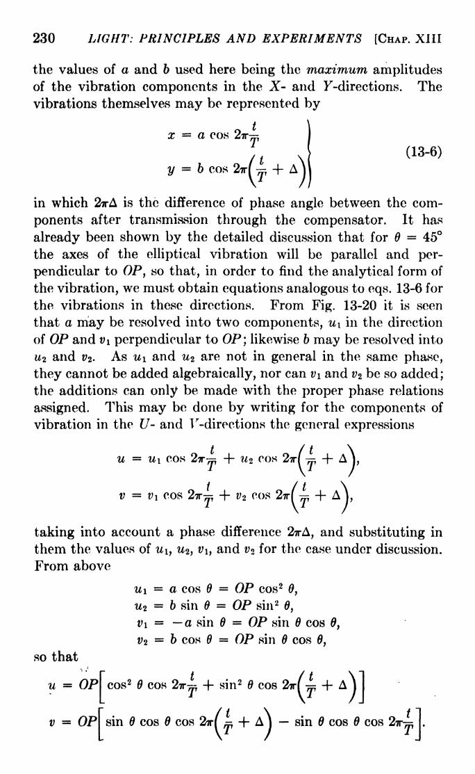
230 LIGHT: PRINCIPLES AND EXPERIMENTS [CHAP. XIII
the values of a and 6 used here being the maximum amplitudesof the vibration components in the X- and F-directions. Thevibrations themselves may be represented by
x = a cos 2ir-~
y = b cos 2ir
(13-6)
in which 2irA is the difference of phase angle between the com-
ponents after transmission through the compensator. It has
already been shown by the detailed discussion that for = 45
the axes of the elliptical vibration will be parallel and per-
pendicular to OP, so that, in order to find the analytical form of
the vibration, we must obtain equations analogous to eqs. 13-6 for
the vibrations in these directions. From Fig. 13-20 it is seen
that a may be resolved into two components, u\ in the direction
of OP and Vi perpendicular to OP] likewise b may be resolved into
u-i and vz . As u\ and HZ are not in general in the same phase,
they cannot be added algebraically, nor can v\ and vz be so added;the additions can only be made with the proper phase relations
assigned. This may be done by writing for the components of
vibration in the U- and Indirections the general expressions
U U\ COS lT
v = v\ cos ?r~
taking into account a phase difference 2?rA, and substituting in
them the values of u\ y u^, Vi, and v for the case under discussion.
From above
u\ = a cos 6 = OP cos26,
HI = b sin B = OP sin 20,
Vi = a sin = OP sin cos 0,
t>2= b cos = OP sin cos 0,
so that
u - OP
v = OP
cos2 cos 2ir-~. + sin 2 cos 2r( -^
sin cos cos 2ir( ^ H- A
Jsisin cos cos
i]

SEC. 13-12] POLARIZATION OF LIGHT 231
The phase number A is 6/X, or the number of wave-lengthsdifference of path in the distance 6 given in eq. 13-5, so we maywrite
2irA = n ). (13-7)
For the special case,= 45, the equations for u and v reduce
to
u
v =
OP2
OPcos
which by a simple trigonometric transformation become
u
cos TrA
V
cos
= OPcos27r(4 + V
= -OP sin 27T
(I+ f>
On squaring and adding, these reduce to
cos 2(A/2)
'
sin2(A/2)
= OP 5
(13-8)
This gives the form of the vibrations for different values of A,
i.e., for different positions in the field of view. If the light trans-
mitted at the position A = is extinguished by a nicol, the inten-
sity at all other positions is given by v* = OP 2 sin 2(A/2),-^
If the light incident upon the compensator is changed from
>lane to elliptically polarized light by means of a quarter-wave
)late inserted between the polarizer and the compensator, in
general there will be a shift of the fringes by an amount dependingjn the ratio of the major and minor axes. There will also be a
change in their blackness since nowhere will the light be plane-
polarizedin the plane extinguished by the analyzer. A rotation
M the analyzer to the angle of extinction will restore the blackness
rf the fringes. \
The value ol 2irA given in eq. 13-7 may be found experimentally.
The entire fringe system may be moved to bring successive dark
fringes under the cross hairs by moving wedge B. If the actual
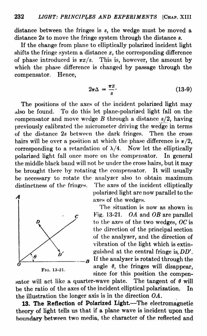
232 LIGHT: PRINCIPLES AND EXPERIMENTS [CHAP. XIII
distance between the fringes is s, the wedge must be moved a
distance 2s to move the fringe system through the distance 8.
If the change from plane to elliptically polarized incident light
shifts the fringe system a distance x, the corresponding difference
of phase introduced is TTX/S. This is, however, the amount bywhich the phase difference is changed by passage through the
compensator. Hence,
27rA - -
(13-9)
The positions of the axes of the incident polarized light mayalso be found. To do this let plane-polarized light fall on the
compensator and move wedge B through a distance s/2, having
previously calibrated the micrometer driving the wedge in terms
of the distance 2s between the dark fringes. Then the cross
hairs will be over a position at which the phase difference is 7r/2,
corresponding to a retardation of A/4. Now let the elliptically
polarized light fall once more on the compensator. In general
the middle black band will not be under the cross hairs, but it maybe brought there by rotating the compensator. It will usually
be necessary to rotate the analyzer also to obtain maximumdistinctness of the fringes. The axes of the incident elliptically
polarized light are now parallel to the^w
axes of the wedges.The situation is now as shown in
Fig. 13-21. OA and OB are parallel
to the axes of the two wedges, OC is
the direction of the principal section
of the analyzer, and the direction of
vibration of the light which is extin-
guished at the central fringe ia,DD'.
If the analyzer is rotated through the
F ^ 13 21 angle 0, the fringes will disappear,since for this position the compen-
sator will act like a quarter-wave plate. The tangent of will
be the ratio of the axes of the incident elliptical polarization. In
the illustration the longer axis is in the direction OA.
13. The Reflection of Polarized Light. The electromagnetic
theory of light tells us that if a plane wave is incident upon the
boundary between two media, the character of the reflected and

SBC. 13-13] POLARIZATION OF LIGHT 233
refracted waves will depend upon the state of polarization of the
wave as well as upon the character of the two media and the angleof incidence. Consider a vector (Fig. 13-22) representing an
electric force at an angle with the plane of incidence to be resolved
into components of amplitude a and 6 perpendicular and parallel,
respectively, to that plane. Then for an isotropic transparentmedium the components of amplitudeai and 61 in the reflected wave are
shown to be given by
sin (i r)CL\
= a~j-. j
r>sm (i + r)
(13-10)
- hl= tan *'
~Surface
tan (i + r)
These equations were originally
derived by Fresnel for the transmis-
sion of light on the assumption of an
elastic-solid medium, although certain
of his assumptions have not been able
to withstand the test of experiment.Flo> 13'22 -
The equations themselves, however, have been experimentally
proved correct.
An examination of eqs. 13-10 and 13-11 discloses that no matter
what i may be, a\ never becomes zero, while for i + r = 90,61 0. This corresponds to the condition for maximum polariza-
tion, in agreement with Brewsler's law.
If the second medium has a higher index of refraction than
the first, i > r, and by eq. 13-10, ai and a are of opposite sign,
which can be interpreted as meaning that on reflection there is a
change of phase IT in the vibrations perpendicular to the plane of
incidence. The vibrations 61 and b parallel to the plane of
incidence are alike in sign if i + r < 90, and different in sign
if i + r > 90. In Fig. 13-22, where i + r is taken less than
90 deg. this sign convention, which may also be interpreted as a
change of phase, is illustrated.
For normal incidence, the sine and the tangent may be replaced
by the angle and, in the limit, eqs. 13-10 and 13-11 become, on
combining with i = nr (SnelFs law)
a, . -<A^4> (13-12)n -f- 1

234 LIGHT: PRINCIPLES AND EXPERIMENTS [CHAP. XIII
and .
*>-if (13-13)
Since a change of phase occurs on reflection, it follows that for
the case of normal incidence, provided n > 1, there will be a
node at the surface and standing waves set up if the reflection
takes place at the surface of a denser medium. Actually the
node will be at the surface only if n = <x>, i.e., if the reflected and
incident waves are equal in amplitude; for reflection at ordinarymedia there is only a minimum at the surface. From the
postulates of the electromagnetic theory it follows also that in
the equation similar to eq. 13-13 for the magnetic force, like signs
in the two sides really mean no difference in phase in the incident
and reflected amplitudes. In order to determine whether the
light is the electric force or the magnetic force in an electro-
V///77
'- Mirror
Fio. 13-23. Fringes appear OH the film where it intersects loop.
magnetic wave, Wiener, Drude, and others performed experi-
ments in which the standing waves were recorded on extremelythin transparent photographic or fluorescent films on plates
inclined at small angles to a mirror surface, as illustrated in Fig.
13-23. These experiments proved conclusively that what wehave described as transverse light vibrations consist of the electric
disturbance in an electromagnetic wave of light frequency. The
experiments also showed that the node at reflection was not at
the surface, but a very small distance below it.
14. Rotation of the Plane of Vibration on Reflection. If the
light incident on a surface is a plane-polarized beam of amplitudeA vibrating in a plane making an angle a with the plane of inci-
dence, the vibration can be resolved into two components, one
of amplitude a = A sin a perpendicular to, and one of ampli-tude b = A cos a parallel to, the plane of incidence. For a
transparent isotropic medium the reflected light will thus have
components of amplitude
A . sin (i r) / ^\ai = A sin a.
-;.-, ( (13-14)
sin (i H- r)
SEC. 13-15] POLARIZATION OF LIGHT 235
perpendicular to, and
61 = A cos aan V* r>
(13-15)tan (i + r)v '
parallel to, the plane of incidence. The reflected plane-polarizedvibration will in general lie in a plane inclined to the plane of
incidence at an angle 0, and the components of the reflected beam
may therefore also be written
a x= B sin 0, (13-16)
6, = B cos 0, (13-17)
perpendicular and parallel, respectively, to the plane of incidence.
From eqs. 13-14, 13-15, 13-16, and 13-17 it follows that
-tan a ^ = tan 0. (13-18)cos (i + r)v '
When the light is incident normally, then tan a = tan 0. Asthe angle of incidence increases, /? becomes greater than a until,
when the angle of complete polarization is reached, tan /3=
oo,
and = 90, in accordance with Brewster's law. For greater
angles of incidence, /? > 90, (90 /3) becomes negative and
finally equals a when i = 90. Equations analogous to those
above may be developed for the case of refraction, and for the
reflection and refraction of elliptically polarized light. Theconclusions thus reached have been tested by experiment and
found to be valid.
15. The Nature of Unpolarized Light. The descriptive
mechanism employed in the discussion of polarized-light phe-nomena often leads the student to infer that the nature of
ordinary light, which has suffered no reflection from, nor trans-
mission through, material media, is disclosed by a dogged applica-
tion of the mechanical picture of linear vibration components.A typical question which arises is, "What is the form of the
transverse vibration in ordinary (unpolarized) light in, say, some
unit element of the beam?" It seems worth while to clarify
this point by indicating the limits to the use of the descriptive
mechanism of the phenomena of polarization. In order to
explain these phenomena, it is found convenient to consider
separately the components of transverse vibration perpendicular
and parallel to a given plane. In many cases, experiment
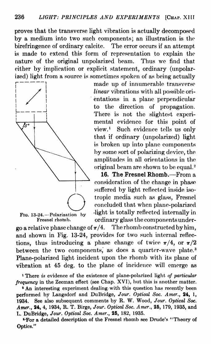
236 LIGHT: PRINCIPLES AND EXPERIMENTS [CHAP. XIII
j
1
proves that the transverse light vibration is actually decomposed
by a medium into two such components; an illustration is the
birefringence of ordinary calcite. The error occurs if an attemptis made to extend this form of representation to explain the
nature of the original unpolarized beam. Thus we find that
either by implication or explicit statement, ordinary (unpolar-
ized) light from a source is sometimes spoken of as being actually
made up of innumerable transverse
linear vibrations with all possible ori-
entations in a plane perpendicularto the direction of propagation.There is not the slightest experi-
mental evidence for this point of
view. 1 Such evidence tells us onlythat if ordinary (unpolarized) light
is broken up into plane components
by some sort of polarizing device, the
amplitudes in all orientations in the
original beam are shown to be equal.2
16. The Fresnel Rhomb. From a
consideration of the change in phasesuffered by light reflected inside iso-
tropic media such as glass, Fresnel
concluded that when plane-polarized
-light is totally reflected internally in
ordinary glass the components under-
go a relative phase change of x/4. The rhomb constructed by him,and shown in Fig. 13-24, provides for two such internal reflec-
tions, thus introducing a phase change of twice 7r/4, or 7r/2
between the two components, as does a quarter-wave plate.3
Plane-polarized light incident upon the rhomb with its plane of
vibration at 45 deg. to the plane of incidence will emerge as
1 There is evidence of the existence of plane-polarized light of particular
frequency in the Zeeman effect (see Chap. XVI), but this is another matter.8 An interesting experiment dealing with this question has recently been
performed by Langsdorf and DuBridge, Jour. Optical Soc. Amer., 24, 1,
1934. See also subsequent comments by R. W. Wood, Jour. Optical Soc.
Amer., 24, 4, 1934, R. T. Birge, Jour. Optical Soc. Amer., 26, 179, 1935, and
L. DuBridge, Jour. Optical Soc. Amer., 25, 182, 1935.
*"For a detailed description of the Fresnel rhomb see Drude's "Theory of
Optics."
Fia. 13-24. Polarization byFresnel rhomb.

SEC. 13-17] POLARIZATION OF LIGHT 237
ircularly polarized light. Moreover, the effect is the same for
ill wave-lengths, since the variation of index of refraction with
wave-length is insufficient to cause any trouble. The disadvan-
tage of the Fresnei rhomb is that the emergent beam, while in
the same direction as the incident, is displaced sideways with
respect to it so that a rotation of the rhomb causes a movementof the image which is difficult to follow with other apparatus.
17. General Treatment of Double Refraction. Thus far
the subject of double refraction has been confined to uniaxial
crystals. These are characterized by possessing a single direc-
tion through the crystal for which there is a common tangent to
the wave fronts of two vibrations in planes perpendicular to each
other. In biaxial crystals, however, the mechanism of wave
propagation is not so simple. In order to explain in a most
general way the optical properties of transparent crystalline
media, Fresnei developed a theory which, though founded on
assumptions which may be criticized,
gave an accurate representation of the
experimental facts. The intention here
is simply to give the conclusions reached
by the theory as to the form of the light
waves propagated through crystals, and
their state of polarization.1 We may
suppose that at any instant many plane
waves are traveling in different direc-
tions through a point (Fig. 13-25) in
a crystal. For each such plane wavethere will be, in general, directions of surface is given by the curved
maximum and minimum velocities of
propagation at right angles to each other. The form of the
wave surface after a given time is represented by the curved line
in Fig. 13-25; it is the common tangent to the plane waves at
that instant. Since in any direction there are in general two
wave velocities, this wave surface consists of two surfaces or
sheets, only one being shown in the figure. The equation of the
wave surface derived by Fresnei is
1 For an extended treatment of Fresnel's theory see Preston, "Theory of
Light"; or Schuster, "Theory of Optics." For a complete treatment of the
subject from the standpoint of the electromagnetic theory of light see
Born, "Optik."

238 LIGHT: PRINCIPLES AND EXPERIMENTS [CHAP. XIII
-T^l? + -^T5 + -T-^2 =0, (13-19)
r 2 a 2 r2 62 r2 c2
where a, 6, and c represent the velocities of propagation throughthe crystal of the vibrations which are respectively parallel to
the x-, y-j and z-axes, and r2 = z2-f- y
2 + z 2- We may consider
that a > b > c. Equation 13-19 may be written
r'2(a
2*24- by2 + cV) - a'2(6
2 + r2)*
2 - 6 2(c
2 + a 2)?/
2
- c2(a2 + 6 2
)z2 + a 26V2 = 0.
The properties of this surface are more easily examined bystudying its projections on the three planes, each of which is
defined by a pair of the coordinate axes.
By putting x =0, we obtain the intersection of the wave
surface and the t/z-plane. The equation of this intersection is
(r2 - a 2
)(6V + c2* 2 - 6V2)=
0,
since in the ?/z-planc r2 =y~ -f- z'
2,and is satisfied by
y2 + z2 = a'2
,
a circle of radius a, and
+ - -1
c2 ^ 62~
'
an ellipse with semiaxes 6 and c, lying entirely within the circle.
Similarly, putting 2 = 0, the intersection with the xy-plane is
shown to be
a circle of radius c, and
! -i- HI =62 "*"
a2
an ellipse with semiaxes a and 6, lying outside the circle. Theintersection with the zz-plane, obtained by putting y =
0, is
a circle of radius 6, and
__|_ _ _ 1
c2^
a2 '
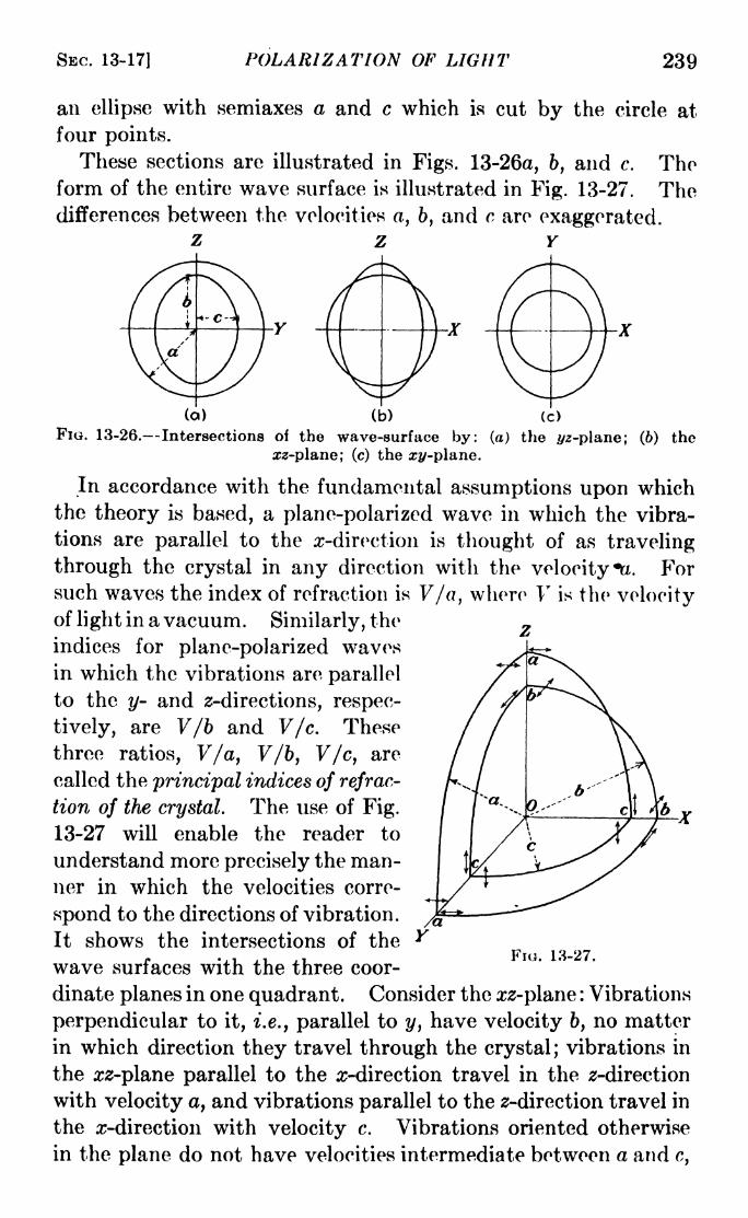
SEC. 13-17] POLARIZATION OF LIGHT 239
an ellipse with semiaxes a and c which is cut by the circle at
four points.
These sections are illustrated in Figs. 13-26a, b, and c. Theform of the entire wave surface is illustrated in Fig. 13-27. Thedifferences between the velocities a, b, and c are exaggerated.
Z Z Y
the
(a) (b)
FIG. 13-26. Intersections of the wave-surface by: (a) the z/2-plane; (6)
a!-plane; (c) the xy-plane.
In accordance with the fundamental assumptions upon whichthe theory is based, a plane-polarized wave in which the vibra-
tions are parallel to the ^-direction is thought of as traveling
through the crystal in any direction with the velocity *tt. Forsuch waves the index of refraction is V/a, where V is the velocityof light in a vacuum. Similarly, the
indices for plane-polarized wavesin which the vibrations are parallel
to the y- and z-directions, respec-
tively, are V/b and V/c. These
three ratios, V/a, V/b, V/c, are
called the principal indices of refrac-
tion of the crystal. The use of Fig.
13-27 will enable the reader to
understand more precisely the man-ner in which the velocities corre-
spond to the directions of vibration.
It shows the intersections of the
wave surfaces with the three coor-
dinate planes in one quadrant. Consider the zz-plane : Vibrations
perpendicular to it, i.e., parallel to y, have velocity 6, no matter
in which direction they travel through the crystal; vibrations in
the zz-plane parallel to the ^-direction travel in the z-direction
with velocity a, and vibrations parallel to the z-direction travel in
the z-direction with velocity c. Vibrations oriented otherwise
in the plane do not have velocities intermediate between a and c,
FIG. 13-27.
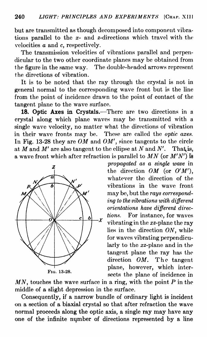
240 LIGHT: PRINCIPLES AND EXPERIMENTS [CHAP. XIII
but are transmitted as though decomposed into component vibra-
tions parallel to the x- and 2-directions which travel with the
velocities a and c, respectively.
The transmission velocities of vibrations parallel and perpen-
dicular to the two other coordinate planes may be obtained from
the figure in the same way. The double-headed arrows represent
the directions of vibration.
It is to be noted that the ray through the crystal is not in
general normal to the corresponding wave front but is the line
from the point of incidence drawn to the point of contact of the
tangent plane to the wave surface.
18. Optic Axes in Crystals. There are two directions in a
crystal along which plane waves may be transmitted with a
single wave velocity, no matter what the directions of vibration
in their wave fronts may be. These are called the optic axes.
In Fig. 13-28 they are OM and OM', since tangents to the circle
at M and M' are also tangent to the ellipse at N and N'. That^is,
a wave front which after refraction is parallel to MN (or M'N') is
propagated as a single wave in
the direction OM (or O'M'),whatever the direction of the
vibrations in the wave front
may be, but the rays correspond-
ing to the vibrations with different
orientations have different direc-
tions. For instance, for waves
vibrating in the zz-plane the raylies in the direction ON, while
for waves vibrating perpendicu-
larly to the zz-plane and in the
tangent plane the ray has the
direction OM. The tangent
plane, however, which inter-
sects the plane of incidence in
MN, touches the wave surface in a ring, with the point P in the
middle of a slight depression in the surface.
Consequently, if a narrow bundle of ordinary light is incident
on a section of a biaxial crystal so that after refraction the wavenormal proceeds along the optic axis, a single ray may have anyone of the infinite number of directions represented by a line
FIG. 13-28.

SEC. 13-19] POLARIZATION OF LIGHT 241
from to a point on the circle of contact, depending on the
particular direction of its vibration, and the rays of the entire
bundle spread out so that each ray becomes a line in the surface
of the circular cone whose apex is at O and whose base is the
circle MN. This is shown by the phenomenon of internal conical
Screen
Fio. 13-29. Internal conical refraction.
refraction. A crystal C (Fig. 13-29) is cut with its faces per-
pendicular to the bisector of the angle between the optic axes,
and a narrow pencil of light is allowed to fall on a limited area
of the surface. In general there will be two images of the hole
on the screen, but for a certain direction O'O of the incident beamthere is a ring of light which has the same diameter for different
distances from the screen. The angle of the cone
of refraction agrees with that predicted by theory.
19. Axes of Single Ray Velocity. The two
directions OP and OP' are called the axes of single
ray velocity. At the points P and P' there is an
infinity of tangents to the surface, two of which, in
the plane of incidence, are illustrated in Fig.
13-30. This is another way of saying that there
is an infinity of wave normals at P. Since the
direction of emergence of the light into the air depends uponthe direction of the wave normal in the crystal, there will be,
corresponding to a ray traversing the crystal in the direction
OP (or OP') a hollow cone of rays leaving the crystal. This
phenomenon, called external conical refraction^ can be demon-strated by the use of the same crystal that is used for demonstrat
Fiti. 13-30.
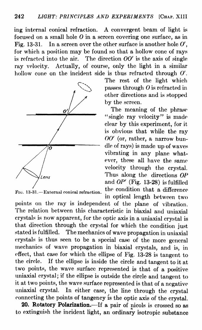
242 LIGHT: PRINCIPLES AND EXPERIMENTS [CHAP. XIII
ing internal conical refraction. A convergent beam of light is
focused on a small hole in a screen covering one surface, as in
Fig. 13-31. In a screen over the other surface is another hole 0',
for which a position may be found so that a hollow cone of rays
is refracted into the air. The direction 00' is the axis of single
ray velocity. Actually, of course, only the light in a similar
hollow cone on the incident side is thus refracted through 0'.
The rest of the light which
passes through is refracted in
other directions and is stopped
by the screen.
The meaning of the phrase"single ray velocity" is made
clear by this experiment, for it
is obvious that while the ray00' (or, rather, a narrow bun-
die of rays) is made up of waves
vibrating in any plane what-
ever, these all have the same
velocity through the crystal.
Lens Thus along the directions OPand OP1
(Fig. 13-28) is fulfilled
Fu, 13-31.-External conical refraction.the C dition that a difference
in optical length between two
points on the ray is independent of the plane of vibration.
The relation between this characteristic in biaxial and uniaxial
crystals is now apparent, for the optic axis in a uniaxial crystal is
that direction through the crystal for which the condition juststated is fulfilled. The mechanics of wave propagation in uniaxial
crystals is thus seen to be a special case of the more generalmechanics of wave propagation in biaxial crystals, and is, in
effect, that case for which the ellipse of Fig. 13-28 is tangent to
the circle. If the ellipse is inside the circle and tangent to it at
two points, the wave surface represented is that of a positiveuniaxial crystal; if the ellipse is outside the circle and tangent to
it at two points, the wave surface represented is that of a negativeuniaxial crystal. In either case, the line through the crystal
connecting the points of tangency is the optic axis of the crystal.20. Rotatory Polarization. If a pair of nicols is crossed so as
to extinguish the incident light, an ordinary isotropic substance

SBC. 13-30] POLARIZATION OF LIGHT 243
placed between them will produce no effect. The same thingis true if a thin section of calcite with its faces perpendicular to
the optic axis is placed between the nicols, provided the light is a
parallel beam. But if a thin section of crystal quartz so cut is
used, light will be transmitted by the analyzer. The analyzer
may then be rotated to an angle at which the light will once morebe extinguished, proving that after passing through the Quartz
plate, it is still plane-polarized but vibrating in a plane different
from that of the light incident on the quartz. From the ordinarylaws of double refraction the failure of the calcite to produce anyeffect was to have been expected, since both the ordinary and
extraordinary rays traverse the crystal in the direction of the
optic axis with the same velocity, and no difference of phase is
introduced between them. From these considerations also the
same result might have been expected with the quartz plate, but
instead there is definite evidence that a rotation of the plane of
vibration has taken place. The use of thicker plates of quartzwill show that the angle of this rotation is proportional to the
thickness traversed.
Crystal quartz and other substances which have this power to
turn through an angle the plane of vibration of a polarized beamtransmitted along the optic axis are said to be optically active.
This property is quite distinct from that possessed by half-wave
plates in effecting a change in the plane of vibration by a relative
retardation between the ordinary and extraordinary plane vibra-
tions, for, as has been seen, the result may be produced when the
light traverses the crystal in a direction along which these two
vibrations have the same velocity. Some crystals rotate the
plane of vibration in a right-handed (clockwise) direction and
others in a left-handed (counterclockwise) direction, and are
accordingly called right-handed or dextrorotatory and left-
handed or levorotatory. Quartz occurs in both forms, the
crystal symmetry of one being the mirror image of that of the
other. A rotation is said to be right-handed when the observer
looking toward the light source sees the plane of polarization
rotated in a clockwise direction. If the crystal is turned around
so that the light traverses it jn the opposite direction, no changein the direction of rotation of the plane of polarization is observed;
destruction of the crystal state, as in the case of fused quartz,
destroys the optical activity of the substance.
244 LIGHT: PRINCIPLES AND EXPERIMENTS [CHAP. XIII
Many liquids and organic substances in solution have been
found to be optically active. A solution of an active substance
in an inactive one possesses a power of optical rotation which is
proportional to the amount of active substance present in a given
quantity of solution. While this rule is generally true, in some
cases the rotation is found to vary slightly with the nature of the
solvent. An approximate formula for the rotation p, in degrees,
is given by
p = A + Bs + Cs2, (13-20)
where s represents the weight of the solvent in 100 parts byweight of solution, and B and C are empirical constants. A is
defined as the molecular rotation of the pure substance, for s = 0,
molecular rotation in turn being defined as the amount of rota-
tion of the plane of polarization produced by a column 10 cm. in
length containing 1 gm. of the substance per cubic centimeter,
or, as the amount of rotation produced by a thickness of 10 cm.
of the pure substance divided by the density of the substance.
For most purposes the second two terms on the right-hand side
of the equation are negligible. The molecular rotation, some-
times called the specific rotation, of sucrose (cane sugar) for the
D-line of sodium (5893 angstroms) is +66.67 deg., the positive
sign indicating that the substance is right-handed. The almost
complete dependence of the angle of rotation on the density of
the optically active substance in solution has made the rotatory
power an extremely useful means of determining the purity of
sugar. The effect produced by a given thickness of a particular
sample may be compared with that of one of standard purity,
and the percentage of foreign substance may thus be determined.
The angle of rotation of the plane of vibration in optically
active substances is nearly proportional to the reciprocal of the
wave-length squared. If the proportionality were exact, the
law could be written p = K/\ z,where K is a constant. A better
agreement with experiment is obtained if to the right-hand side
of the equation are added terms whose values depend on natural
free periods of vibration in the crystal.l The relation between the
rotation and wave-length is called dispersion of the rotation.
21. FresnePs Theory of Rotatory Polarization. Fresnel
assumed that the incident plane-polarized light upon entering the
1 For a more complete discussion of this topic, see Drude, "Optics."

SBC. 13-21] POLARIZATION OF LIGHT 245
quartz was broken into two beams circularly polarized in oppositedirections and propagated through the crystal with different
velocities. In Fig. 13-32a and 6 are represented two opposite
circular vibrations in which, when they are superposed, the linear
components in the X-direction will neutralize each other, leaving
only a plane vibration in the F-direction as in Fig. 13-32c. But
if the left-handed vibration travels through the crystal faster
(a) (b) (c)
Fi. 13-32.
(d)
than the right-handed, after emergence from the crystal the
components in a direction represented by U (Fig. 13-32rf) will
neutralize each other, leaving only a plane vibration in the
F-direction. The angle between the Y- and V-directions dependson the relative velocities of the two circular vibrations and the
thickness of crystal traversed.
If this explanation is correct, then the two vibrations, since
they travel with different velocities, should undergo different
Fio. 13-33.
amounts of bending by refraction at an oblique surface. Fresnel
found that the resulting separation of the beams, while very small,
could be detected if a narrow beam is passed through a block
made of alternate prisms of right- and left-handed quartz, as
illustrated in Fig. 13-33, the prisms being cut so that the light
traversed them in the general direction of the optic axis. While
in the first prism the left-handed circularly polarized beam travels
faster than the right-handed, in the second it travels slower.
Since the light is incident upon each oblique face at a large angle,
refraction of the two components takes place at slightly different
angles at each face, thus increasing the separation of the beams.

246 LIGHT: PRINCIPLES AND EXPERIMENTS [CHAP. XIII
Upon examination with a quarter-wave plate and an analyzer,the two beams may be shown to be circularly polarized in opposite
directions.
The rotation of the plane of vibration can be described analyti-
cally as follows: Let
X\ ad
= a sin - -
represent a left-handed circular vibration, and
d= a cos - - -
T r wi i (t
i z (i sin -7-1 t
)
a right-handed circular vibration, the two having the same period
and amplitude and traveling in the same direction with velocities
V} and vz , respectively, through a crystal of thickness d. Super-
position of the two can be represented by adding the X-compo-nents and the F-components separately, i.e.,
X = X,
Y = yi
F 27rA=a[
cos ^^- cos
y, = a. 27Tsm ~ . 27T/ r/\l~ sm
"^v s;}
which may be changed to the form
X = 2a cos -=f
y = 2a cos -7=7
*
2U,+
i
4 I I
*1
2'+
Trrffl 1 1cos -7=7 >
^1^2 VlJ(13-21)
according to which the X- and y-components of the combined
vibration have the same phase, hence the result is a plane-
polarized vibration. The plane of this vibration is given by
(13-22)y _ T^/i i
x~ tan Y^
~r
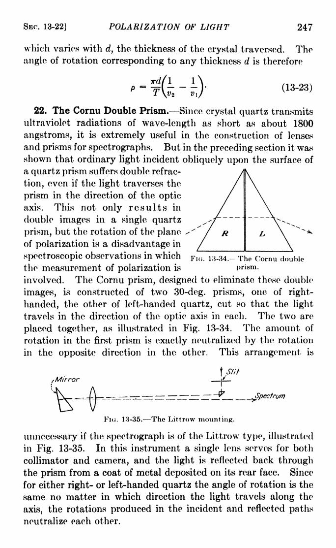
SEC. 13-22] POLARIZATION OF LIGHT 247
which varies with d, the thickness of the crystal traversed. The
angle of rotation corresponding to any thickness d is therefore
(13-23)p--srt---
22. The Cornu Double Prism. Since crystal quartz transmits
ultraviolet radiations of wave-length as short as about 1800
angstroms, it is extremely useful in the construction of lenses
and prisms for spectrographs. But in the preceding section it wasshown that ordinary light incident obliquely upon the surface of
a quartz prism suffers double refrac-
tion, even if the light traverses the
prism in the direction of the optic
axis. This not only results in
double images in a single quartz
prism, but the rotation of the planeof polarization is a disadvantage in
spectroscopic observations in which
the measurement of polarization is
involved. The Cornu prism, designed to eliminate these double
images, is constructed of two 30-deg. prisms, one of right-
handed, the other of left-handed quartz, cut so that the light
travels in the direction of the optic axis in each. The two are
placed together, as illustrated in Fig. 13-34. The amount of
rotation in the first prism is exactly neutralized by the rotation
in the opposite direction in the other. This arrangement is
FIG. 13-34.- The Cornu double
prism.
tMirrort\i
__---- - ^--~ ~ ___^Spectrum
Fiu. 13-35. The Littrow mounting.
unnecessary if the spectrograph is of the Littrow type, illustrated
in Fig. 13-35. In this instrument a single lens serves for both
collimator and camera, and the light is reflected back through
the prism from a coat of metal deposited on its rear face. Since
for either right- or left-handed quartz the angle of rotation is the
same no matter in which direction the light travels along the
axis, the rotations produced in the incident and reflected paths
neutralize each other.

248 LIGHT: PRINCIPLES AND EXPERIMENTS [CHAP. XIII
23. Half-shade Plates and Prisms. Measurements of rotatory
polarization may be made by setting a pair of nicols for extinction,
interposing the optically active substance between them, and
recording the angle through which the analyzer is turned to
produce extinction once more. This method is not very accurate,
because it is difficult to tell just when the light is completely cut
off. Since a determination of equality of intensity of two parts
of the field may be made with greater accuracy, it is customary to
introduce into the optical path some device for substituting this
setting for the setting for extinction. One of these, the Laurent
half-shade plate, consists of a semicircular half-wave plate of
quartz or other crystal set between the polarizer and analyzer
and close to the former, with its optic axis at a small angle 6
with the principal section of the polarizer. In order to com-
pensate for the absorption and reflection of this plate, the other
half of the field is covered with a piece of glass of appropriate
color and thickness. The smaller the angle 0, the greater the
change in relative intensity of the two halves of the field of view
when the analyzer is rotated. For small values of 6, however,the intensity in both halves will be small. For this reason it is
customary to mount the half-wave plate to permit its adjustmentover a small range of angle. The observations are made by
turning the analyzer until the two halves of the field are equally
bright. In some instruments a small nicol covering one half of
the field is substituted for the Laurent plate.
Another device which serves the same purpose as the Laurent
plate is the Cornu-Jellet prism. This is made by splitting a
nicol in a plane parallel to the
direction of vibration of the trans-
mitted light, and removing a sec-
tion, as illustrated in Fig. 13-36a.
(a) (b) When the two pieces are joinedFIG. 13-36. The Cornu-Jellet
together, as showri in Fig. 13-366,
the planes of vibration of the light
transmitted by the two halves make a small angle with each other,and extinction takes place for different settings of the analyzer.When the beam through one half is extinguished, a small amountof light is transmitted through the other. In making observa-
tions of the rotation of the plane of polarization in a substance,it is customary to set the analyzer with its plane of transmission
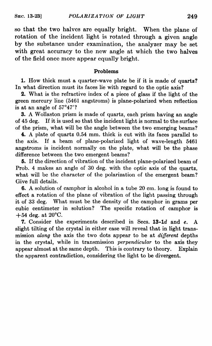
SEC. 13-23] POLARIZATION OF LIGHT 249
so that the two halves are equally bright. When the plane of
rotation of the incident light is rotated through a given angle
by the substance under examination, the analyzer may be set
with great accuracy to the new angle at which the two halves
of the field once more appear equally bright.
Problems
1. How thick must a quarter-wave plate be if it is made of quartz?In what direction must its faces lie with regard to the optic axis?
2. What is the refractive index of a piece of glass if the light of the
green mercury line (5461 angstroms) is plane-polarized when reflection
is at an angle of 5747'?
3. A Wollaston prism is made of quartz, each prism having an angleof 45 deg. If it is used so that the incident light is normal to the surface
of the prism, what will be the angle between the two emerging beams?4. A plate of quartz 0.54 mm. thick is cut with its faces parallel to
the axis. If a beam of plane-polarized light of wave-length 5461
angstroms is incident normally on the plate, what will be the phasedifference between the two emergent beams?
5. If the direction of vibration of the incident plane-polarized beam of
Prob. 4 makes an angle of 30 deg. with the optic axis of the quartz,
what will be the character of the polarization of the emergent beam?Give full details.
6. A solution of camphor in alcohol in a tube 20 cm. long is found to
effect a rotation of the plane of vibration of the light passing throughit of 33 deg. What must be the density of the camphor in grams percubic centimeter in solution? The specific rotation of camphor is
+54 deg. at 20C.7. Consider the experiments described in Sees. 13-ld and e. A
slight tilting of the crystal in either case will reveal that in light trans-
mission along the axis the two dots appear to be at different depthsin the crystal, while in transmission perpendicular to the axis they
appear almost at the same depth. This is contrary to theory. Explainthe apparent contradiction, considering the light to be divergent.

CHAPTER XIV
SPECTRA
1. Kinds of Spectra. In general there are three kinds of
spectra :
a. Bright Line Spectra. These have their origin in incandescent
gases at low pressure as in a partly evacuated discharge tube, in
flames, in the glowing gas between the terminals of an electric
arc or spark, and in certain so-called gaseous nebulae such as the
irregular nebula in Orion, and in the tails of comets. The
spectrum seen when only the edge of the sun is observed througha spectroscope is a bright line spectrum. In the majority of
cases, bright line spectra are those of monatomic gases, althoughcertain of them called band spectra are due to molecules.
6. Continuous Spectra. These are due to incandescent solijds
or liquids, such as a lamp filament, the poles of an electric arc,
molten metals of high melting point, and also to incandescent
gases at high pressure such as exist in lower levels in stars.
Gases at low pressures for which the most conspicuous spectrumis one of bright line emission may under certain circumstances
also emit a spectrum which is continuous over a given spectral
range. The manner in which spectral theory explains this typeof emission will be given in later sections.
c. Absorption Spectra. These are in general of two sorts:
continuous absorption, and line absorption. A type of con-
tinuous absorption, i.e., over a considerable range of wave-length,will be discussed briefly in the sections on dispersion. Line-
absorption spectra commonly occur when the light from a source
emitting a continuous spectrum is observed with a spectroscopeafter passing through gases at low pressure and lower temperaturethan that of the source. For the production of this type of
spectrum, it is necessary that the atoms or molecules of the
intervening gas be in a condition.to absorb energy of radiation
which strikes them. The mechanism of this line absorption is
explained on the basis of the quantum theory of spectra.
2. Early Work on Spectra. Although the dispersion of light
into a spectrum by a prism had been studied by Kepler and others,250

SEC. 14-3] SPECTRA 251
Newton was the first to formulate the precise laws of dispersion.
He invented the word "spectrum" for the band of color obtained
from the sun's light with a prism. Fraunhofer's discovery of the
significance of the absorption lines in the solar spectrum1 was
the beginning of what might be called the first pioneering era in
spectroscopy, which lasted for about 30 years after Fraunhofer's
discovery.
The relationship existing between laboratory and celestial
spectra was first clearly stated by Kirchhoff in 1859. Byexhaustive experiments carried out in collaboration with Bunsen,he showed that if a burning salt is placed between any hotter
source of a continuous white-light spectrum and the spectroscope,there will be seen a spectrum crossed by absorption lines whose
positions coincide with the bright lines obtained from the burningsalts alone. His conclusion was that the cooler flame absorbs
light of the same wave-length as it will emit. He inferred there-
fore that the Fraunhofer lines in the solar spectrum are due to
the presence of a solar atmosphere cooler than the underlying
body of the sun, and containing the same elements which give rise
to corresponding bright lines in the laboratory. A year or two after
the announcement of these conclusions he published the funda-
mental law of radiation and absorption: The ratio between the
absorptivity and emissive power is the same for each kind of rays
for all bodies at the same temperature.
3. The Balmer Formula for Hydrogen. The half century
following Kirchhoff was a period of accelerated accumulation of
experimental data and technique, much of which was in the field
of astrophysics. Engrossing as the story of these developments
may be, it cannot be told here. 2 The first step toward precise
knowledge of the origin of spectra was made in 1885 by Balmer,who showed that with a high degree of approximation the wave-
lengths of the hydrogen lines could be fitted into the formula
= 3645
1 See Sec. 6-14.2 The reader is referred to Crew, "Rise of Modern Physics," Scheiner,
"Astrophysical Spectroscopy," and Lockyer, "Inorganic Evolution as
Studied by Spectrum Analysis," for the history and background of spec-
troscopy during this period.

252 LIGHT: PRINCIPLES AND EXPERIMENTS [CHAP. XIV
where n is an integer equal to or greater than 3, and X is in
angstroms.4. The Rydberg Number. It is a little easier to connect this
formula with developments to be described later if a change is
made from wave-length (X) to wave number (v), the number of
waves in a centimeter in vacuo. We then have
'-^- 3\ (14-2)
in which n =3, 4, 5 . . .
,and R has the approximate value
109,700. In 1890, Rydberg discovered that the number R is
with slight variations common to all elements. For any particu-
lar element the formula is
For instance, with this formula the wave numbers of certain
lines in the helium spectrum are given with the atomic number 1 of
helium Z 2, rii=
3, n2=
4, 5, 6, etc. It may be perplexing
to the student that in illustrating eq. 14-3 by choosing n\ = 3
instead of 2, for helium, nothing is said to indicate the reason for
that choice. That reason will appear in the following sections.
5. Series in Spectra. The lines of the hydrogen spectrum
given by the Balmer formula (eq. 14-1) constitute what is called
a series. Several years before Balmer's discovery it was noticed
that in the spectra of several elements, notably those of sodium
and potassium, most of the lines could be fitted into series. In
these spectra there is not a single series of lines, as in hydrogen,but several series, each of which is extended throughout the
spectrum. Also, the series themselves consist of doublets,
triplets, or higher multiple groups. Since the lines in different
series for a given element are different in appearance, some being
predominantly strong, others diffuse, others sharp, etc., it became
customary to classify series as principal, sharp, diffuse, funda-
mental, etc., the letters P, S, D, F, etc., being used for convenience.
Because of the existence of a real physical significance to these
differences of appearance, the letters have remained in the nota-
1 By "atomic number" is meant the ordinal number of the atom in the
periodic table of the elements, beginning with hydrogen as number one.

SBC. 14-6| SPECTRA 253
tion of spectral theory. In Fig. 14-1 are some reproductions of
spectra showing series. 1
6. The Hydrogen Series. It occurred independently to two
workers in this field, Rydberg and Ritz, that in the Balmer
formula (eq. 14-3) n\ might be a running integer as well as n*.
For instance, if, as in the Balmer formula, n\ = 2, n2=
3, 4,
DIFFUSEI III
FIQ. 14-1. The spectrum of sodium, showing the principal series doublet andsome members of the sharp and diffuse series. The principal series doublet
(5890 and 5896 angstroms) is overexposed and surrounded by Rowland ghostsdue to imperfections in the diffraction grating used. The other lines in the
spectrum are due to impurities in the source.
5, . . ., etc., the series of wave-lengths represented is 6563,
4861, 4340 angstroms, . . ., etc., while if n\ is put equal to 1,
and tt2 put equal to 2, 3, 4, 5, etc., successively, the calculations
yield the wave-lengths 1216, 1026, 972 angstroms, . . ., etc.,
fractional parts of angstroms being omitted. These lines, lying
in the far ultraviolet, were observed by Lyman. Thus far, five
series of hydrogen spectra have been observed. These are listed
below, designated in accordance with custom by the names of
the original observers. The values of ni and nz are given in
each case.
HYDROGEN SERIES OP ATOMIC SPECTRA
Lyman series:
p -^*2j,
n 2, 3, 4, 5, etc.
1 For summary of the work in this subject see Fowler, "Report on series
in Line Spectra," Fleetway Press, 1922; or White, "Introduction to Atomic
Spectra," McGraw-Hill.

254 LIGHT: PRINCIPLES AND EXPERIMENTS [CHAP. XIV
Balmer series:
/I 1\v = R(
22~
^2 ), n =3, 4, 5, 6, etc.
Paschen series:
/I _ 1\=
#(32 n2 ), n =4, 5, 6, 7, etc.
Bracket! series:
/I 1\=
#(42 ^2 1, n =5, 6, 7, 8, etc.
Pfund series:
=6, 7, 8, 9, etc.
The last three of these series lie in the infrared, as can be
verified by calculation.
It is now evident that for any element a fair approximation to
the wave numbers of series is given by eq. 14-3, and that the
illustration at the end of Sec. 14-4 gives only one of the series
of the helium spectrum^ Others will correspond to different
values of n\ and n2 ,in accordance with the rules laid down. It
must be kept in mind, however, that only the simplest of series
formulas have been presented here. Others which give a closer
approximation to the wave-lengths may be found in treatises on
the subject of line spectra.
7. The Quantum Theory of Spectra. The attention of manyspectroscopists was focused upon series relations in spectra from
the time of Balmer's discovery, but it was not until the announce-
ment of the Bohr theory about 30 years later that the physical
significance of these relations was disclosed. Series relations
still are spectroscopic tools of tremendous power, for, by their
aid, if several lines of a spectral series are experimentally identi-
fied, the wave-lengths of the rest can be predicted. During the
quarter century following Balmer's discovery, however, there
remained unsolved the riddle of spectra: What, precisely, is the
connection between the wave-lengths of the radiation and the
changes in the atoms or molecules from which that radiation is
emitted? The answer to this question did not follow from series
relations in spectra. Several lines of investigation convergingto a common end, and brought together by the insight of Niels

SEC. 14-9] SPECTRA 255
Bohr, gave us a theoretical explanation which later was expandedinto what might be called the quantum theory of spectra. Thelines of investigation contributing to this end will now be taken
up in detail.
8. KirchhofFs Law of Emission and Absorption. In order to
trace the events leading to modern theories of spectra, it is
necessary to outline the developments in the field of radiation
which followed the work of Kirchhoff. 1
The relation between emission and absorption deduced byKirchhoff and mentioned in Sec. 14-2 rests on more extensive
grounds than observations on solar aborption. A study of their
characteristics shows that certain substances such as lampblack,
deep-piled velvet, etc., absorb a greater amount of the radiation
that falls upon them than other substances, while at the same
time they also act as good radiators. Experiments with such
surfaces led to the theoretical concept of a perfect black body,
which may be defined as one whose surface absorbs all the radia-
tion falling upon it. Obviously this (ideal) surface does not
reflect at all. For any surface, the fraction of the radiation,
falling upon its surface, which is absorbed is called the absorp-
tivity of the surface. Similarly, the emissive power of a body is
defined as the total radiation emitted per unit time per unit area
of its surface. From both experimental and theoretical con-
siderations, Kirchhoff was led to the general law of radiation
connecting these quantities and stated in the next section.
9. KirchhofPs Radiation Law. The relation between absorp-
tivity (A) and emissive power (E) is given by Kirchhoff's law,
which may be stated as
Tjl
-j= constant (14-4)
at a given temperature, for all bodies. Since A 1 for a so-called
perfect black-body radiator, it follows that the law may be stated,
in words: at a given temperature, the ratio of the emissive power to
the absorptivity of any body is the same for all bodies and is equal
to the emissive power of a black body at the same temperature.
1 For a more detailed discussion of these developments, as well as of the
quantum theory of spectra, the reader is referred to Richtmyer, "Intro-
duction to Modern Physics," McGraw-Hill, and Reiche, "Quantum
Theory," Dutton.

256 LIGHT: PRINCIPLES AND EXPERIMENTS [CHAP. XIV
10. Stefan-Boltzmann Law. In 1879, Stefan proposed the
relationshipE = ffT\ (14-5)
where E is the total emissive power of a black body at an absolute
temperature T, and <r* is a constant. Subsequently, the same
law was deduced theoretically by Boltzmann, who applied the
reasoning of the Carnot cycle of energy exchange in heat engines
to a hypothetical engine in which radiation was the working
substance. The Stefan-Boltzmann law has been verified
experimentally. It should be
emphasized that the radiation dealt
with has a continuous spectrum.
11. Wien's Displacement Laws.
In 1893, on the basis of classical
thermodynamics, Wien announced
his famous wavelength-temperature
displacement law, which may be putin the form
T = constant, (14-6)Wavelength
FIG. 14-2. showing the dis- in which XmM is the wave-length for
placement toward the violet, with which tjiere js the maximum energyincreasing temperature, of the
wave-length (xmajt) of the energy of radiation at absolute temperaturemaximum. y The yalue^^e constant prod-
uct is found to be 0.2884 cm.-deg. By the particular nature of
the theoretical considerations upon which the law is based, Wien
was enabled to obtain another relation, namely, the energy-
temperature displacement law, which may be written
t
UJ
= constant X (14-7)
where Em** is the energy of radiation at the maximum for T.
These laws have been verified by experiment. Equation 14-6 is
illustrated graphically in Fig. 14-2. Further comprehension
of the significance of the displacement laws may be gained byconsideration of Fig. 14-3, in which are plotted as ordinates
experimental values of E\/T* against values of XT' as abscissae
for three temperatures. E\ is an expression for the energy
* The experimental value of a is usually given as 5.735 X 10~6erg cm.~a
deg.~~4 sec." 1
.
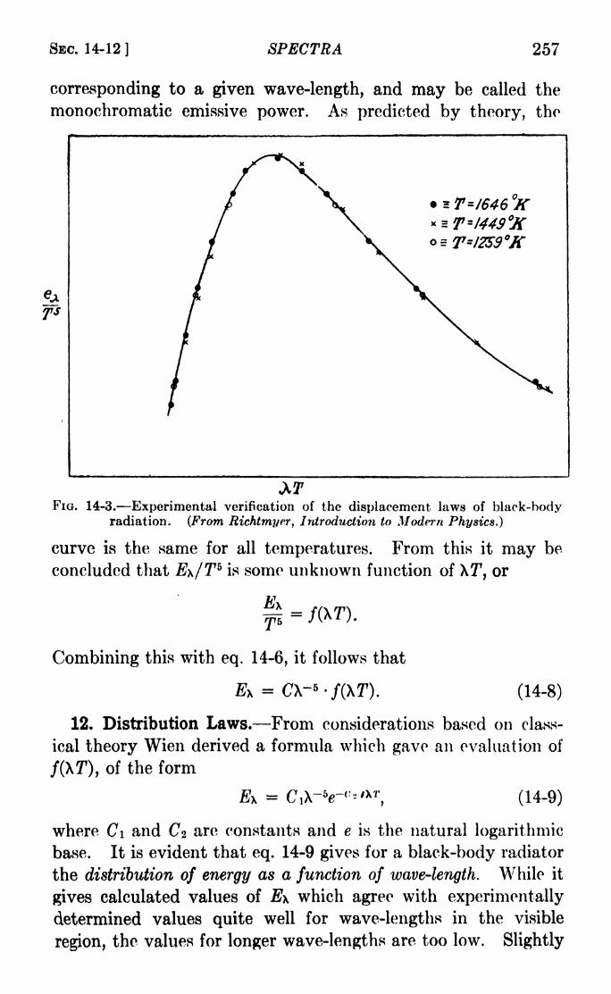
SBC. 14-12] SPECTRA 257
corresponding to a given wave-length, and may be called the
monochromatic emissive power. As predicted by theory, tho
FIG. 14-3. Experimental verification of the displacement laws of black-bodyradiation. (From Richtmyer, Introduction to Modern Physics.)
curve is the same for all temperatures. From this it may be
concluded that E\/T5is some unknown function of XT, or
Combining this with eq. 14-6, it follows that
Ei = C\-*-f(\T). (14-8)
12. Distribution Laws. From considerations based on class-
ical theory Wien derived a formula which gave an evaluation of
/(XT), of the form
= C,X-V-<'"* 7
', (14-9)
where Ci and C% are constants and e is the natural logarithmic
base. It is evident that eq. 14-9 gives for a black-body radiator
the distribution of energy as a function of wave-length. While it
gives calculated values of E\ which agree with experimentally
determined values quite well for wave-lengths in the visible
region, the values for longer wave-lengths are too low. Slightly

258 LIGHT: PRINCIPLES AND EXPERIMENTS [CHAP. XIV
different distribution formulas, obtained by various processes of
deduction based on classical theory, were obtained by others,
notably the Rayleigh formula
(14-10)
in which C\ and Cz are not necessarily the same constants as in
Wien's formula. Rayleigh's theoretical treatment was later
extended by Jeans, who proposed the formula
J0x = Cm- 4, (14-11)
in which C is a constant and kT is the total energy associated
with each degree of freedom of the medium in which the radiation
is supposed to exist.1 The formulas of Rayleigh and Rayleigh-
Jeans agree with experiment for very long waves, but they give
values which are too high in the visible spectrum.13. Planck's Quantum Hypothesis. Experimental tests car-
ried out by Lummer and Pringsheim proved conclusively that
none of the distribution laws completely agreed with observa-
tions. Numerous attempts to modify the formulas derived from
classical theory so as to bring complete agreement with experi-
ment failed. Finally, in 1900, Planck decided to alter his methodof deducing the distribution law by introducing a new and radical
concept. In all previous deductions, the energy of radiation
had been supposed to be divided among a great many hypo-thetical "oscillators" in the black body. In arriving at the
mean energy it had been customary to suppose that an individual
oscillator might possess any possible quantity of energy.
Planck's radical departure consisted in postulating that the
energy of the radiator was divided into a finite number of discrete
units of energy of magnitude e, these energy units or "quanta"
being distributed at random among the individual oscillators.
The mftnber of different ways in which this distribution of energy
may be divided among the oscillators was called by Planck the
thermodynamic probability of a particular arrangement or dis-
tribution. Making use of well-established rules of mathematical
1 It should be kept in mind that no attempt is made here to give the
student a complete understanding of the theoretical bases of these formulas.
Fascinating as the development of the subject is, it is intended here only to
introduce the formulas so as to contrast them with the more successful
formula of Planck, whose work was part of the prelude to the quantum
theory of spectra.

SBC. 14-14] SPECTRA 259
procedure, with the aid of this novel concept Planck arrived at an
expression for the mean energy V of an oscillator:
V -
in which A; is a constant. But from classical considerations alone,
Planck had deduced that
E* =]?
(14-13)
while it is evident from eq. 14-8 that the displacement laws, which
are in rigorous agreement with experiment, hold that E\ is pro-
portional to some function /(XT7
). Hence it follows that U is
proportional to some function of (XT7
). Planck concluded that
in view of the form of eq. 14-12, and the necessity for keeping in
agreement with the displacement laws, it followed that
=
where v is the frequency of the radiation and h is a constant.
The symbol h stands for Planck's quantum of action and has the
value 6.547 X 10~27erg sec. Planck's distribution formula is
where Ci and c2* are constants. For short waves this is the same
as Wien's formula, and for long waves is the same as the Ray-leigh-Jeans formula.
14. The Rutherford Atom Model. During the time when the
laws of radiation were engaging the attention of many research
workers, and in the decade following, older concepts of the nature
of matter were being subjected to rigorous scrutiny. The dis-
covery of radioactivity and the development of the concept of a
fundamental unit of electrical charge, the electron, stimulated
experiments which showed conclusively that the older ideas
concerning the structure of atoms must be modified. Finally,
in 1911, on the basis of experimental results obtained in a lengthy
investigation of the manner in which a-particles were scattered
* c2 is equal to hc/k, where c is the velocity of light, and k is Boltzmann's
constant, the gas constant Ro divided by the Avogadro number No- k has
the value 1.3708 X 10~ 16erg deg.-. The value of c2 is 1.432 cm.-deg.
260 LIGHT: PRINCIPLES AND EXPERIMENTS [CHAP. XIV
by thin metallic foil, Rutherford postulated that an atom con-
sisted of a positively charged nucleus of extremely small dimen-
sions, surrounded by planetary negatively charged electrons,
the distances between the electrons and the nucleus being very
great compared to the dimensions of the charged particles
themselves.
16. The Bohr Theory of Spectra. At first it seemed as if the
Rutherford atom model would lead the way on classical groundsto a solution of the riddle of emission (bright line) spectra, for it
can be shown that the frequency of revolution of the planetaryelectrons depends upon the energy of the atom. On the other
hand, the radiation of any part of the energy would necessarily
lead to a gradual change of that frequency, and hence to the
emission of a continuous spectrum, and not the separate line
spectra which are observed. The problem, for the hydrogenatom at least, was finally solved by Bohr, who assumed the
Rutherford atom model, and in addition made three hypotheses
concerning the manner in which the radiation takes place.
Bohr assumed, first, that the planetary electrons revolve about
the nucleus, not in all possible paths but only in certain discrete
orbits. He assumed that the orbits are circular and are
limited to those for which the angular momentum is an integral
multiple of h/2ir, where h is Planck's quantum constant. Heassumed, second, that no radiation takes place while an electron
remains in one of these orbits, but only when it passes from a
given orbit to one of lesser energy, i.e., to one of smaller radius.
He assumed, third, that when the electron passes from one of these
quantum orbits of energy TF2 to one of lesser energy W\, radiation
is emitted whose frequency, v, i,s given by1
c Wi-v =
x=-~h
The calculation of the values of Wz and W\ for hydrogen is
simple. If a is the radius of a given orbit, e the charge on the
electron, and E the charge on the nucleus, then the force of
attraction is eE/a?. For equilibrium this must be equal to the
1 In making this assumption, Bohr was adopting not only Planck's
hypothesis, but a far more drastic one proposed by Einstein to explain the
photoelectric effect (see Sec. 15-20).

SEC. 14-15] SPECTRA 261
centrifugal force on the electron, which is mow2,where m is the
mass of the electron and o> the angular velocity, or
ma3o>
2 = eE. - (14-16)
If Z is the atomic number, then E = eZ. Also, by Bohr's
first hypothesis, the angular momentum is a multiple of h/2ir,
or
(14-17)
where n is an integer. From eqs. 14-16 and 14-17 it is possible
to obtain values of an and,the radius and angular velocity
corresponding to orbit n.
and
C0n
(14-18)
The total energy W in an orbit is the sum of the kinetic and
potential energies, or
IT/ 2 2W = prWa20>
2 --;
2 a
which by the use of eq. 14-16 becomes
p*ZW = -~2a
Combining this expression with the first of eqs. 14-18, it follows
that
Combining this expression with eq. 14-15, we obtain finally
' -A- ^rfe -
i) (14-19)
This may now be compared with the Rydberg formula, eq. 14-3.
While v is the wave number, v is the frequency, so that vc = v.
262 LIGHT: PRINCIPLES AND EXPERIMENTS [CHAP. XIV
Hence it follows from eqs. 14-3 and 14-19 that the Rydbergnumber is
2ir2e4w
a result which may be verified by calculation, given
e = 4.770 X 10- 10 e.s.u.
m = 9. X 10~28gr.
h = 6.547 X 10~27erg sec.
c = 2.998 X 10 10 cm. sec.- 1
.
Although the Bohr formula gives values of the wave-lengths
agreeing well with experiment for hydrogen, much more extensive
hypotheses have been necessary to formulate a quantum theoryDf spectra which holds for all atomic and molecular radiation.
It is found, for instance, that the concept of circular orbits fails.
The existence of discrete energy states, however, is completely
verified, as is also the concept, expressed in eq. 14-15, that the
Frequency of a given spectrum line is proportional to the differ-
ences of energies of the beginning and end energy states involved
in a transition of an electron from a higher to a lower energystate.
It was pointed out in Sec. 14-4 that the Rydberg number is
nearly the same for all elements. The slight variation is because
of the effect of the mass of the nucleus, which has been neglected
in the preceding discussion. From elementary mechanics it
Follows that instead of m, the mass of the electron, the quantity
mM/(m + M) twhere M is the mass of the nucleus, should be
used in eq. 14-19. Then the value of R conforms more closely
to the experimental values. The value of M may be calculated
from
_ atomic wt. of element X mass of oxygen atom___
The quantity mM/(m -f- M) is known as the reduced mass. It
approaches m as M approaches .
16. Energy-level Diagrams. In the foregoing sections an
explanation has been presented of the manner in which the simple
Bohr formula in terms of physical quantities such as the chargeon and mass of the electron, Planck's constant, and the atomic
number, may be applied to give the wave-lengths of atomic
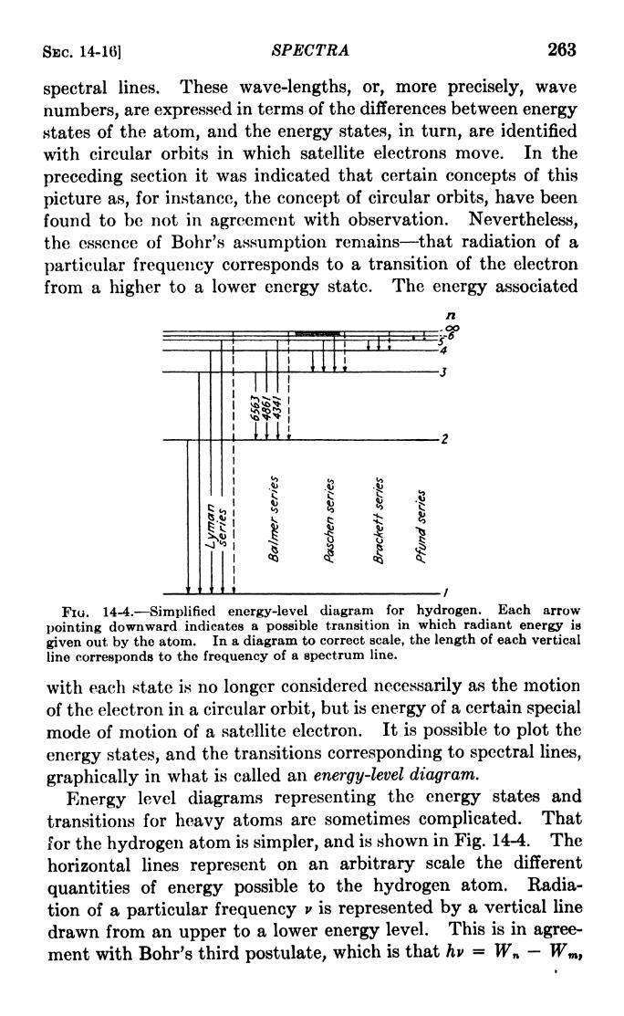
SBC. 14-16] SPECTRA 263
spectral lines. These wave-lengths, or, more precisely, wave
numbers, are expressed in terms of the differences between energy
states of the atom, and the energy states, in turn, are identified
with circular orbits in which satellite electrons move. In the
preceding section it was indicated that certain concepts of this
picture as, for instance, the concept of circular orbits, have been
found to be not in agreement with observation. Nevertheless,
the essence of Bohr's assumption remains that radiation of a
particular frequency corresponds to a transition of the electron
from a higher to a lower energy state. The energy associated
n
FIG. 14-4. Simplified energy-level diagram for hydrogen. Each arrow
pointing downward indicates a possible transition in which radiant energy is
given out by the atom. In a diagram to correct scale, the length of each vertical
line corresponds to the frequency of a spectrum line.
with each state is no longer considered necessarily as the motion
of the electron in a circular orbit, but is energy of a certain special
mode of motion of a satellite electron. It is possible to plot the
energy states, and the transitions corresponding to spectral lines,
graphically in what is called an energy-level diagram.
Energy level diagrams representing the energy states and
transitions for heavy atoms are sometimes complicated. That
for the hydrogen atom is simpler, and is shown in Fig. 14-4. The
horizontal lines represent on an arbitrary scale the different
quantities of energy possible to the hydrogen atom. Radia-
tion of a particular frequency v is represented by a vertical line
drawn from an upper to a lower energy level. This is in agree-
ment with Bohr's third postulate, which is that hv = Wn- Wm,
264 LIGHT: PRINCIPLES AND EXPERIMENTS [CHAP. XIV
where Wn and Wm are the higher and lower energy states,
respectively.
17. Band Spectra of Molecules. In addition to the so-called
line spectra due.to emission of radiation by atoms, there is another
type of spectrum due to radiation by molecules. The former
consist in the main of spectral lines which for any particular
series are far apart, while the latter, called band spectra, appearwith sufficient dispersion to be bands of closely grouped lines
having a definite regularity in their spacing and, in many cases,
with insufficient dispersion, to be continuous. A band is charac-
terized by a head) either on the violet or red side, the lines there
being usually so close as to be indistinguishable, and becoming
gradually more widely spaced and fainter toward the tail (see
Fig. 14-6). Bands having the head on the violet side are said
to be degraded toward the red, while those having the head on the
red side are degraded toward the violet. For heavy molecules
such as Mn0 2 , 84, etc., the bands are more closely spaced than
for light molecules such as CO, N2, etc., while the series of bands
belonging to H2 are so widely spaced and overlap to such an
extent that the system resembles an atomic spectrum.As in the simple Bohr theory of atomic spectra, the energy
states in the molecule are limited to those for which the angular
momentum due to its rotation is an integral multiple of h/2ir.
Using j for the running number indicating different states
(i.e.,j 0, 1, 2, etc.), and deriving from mechanics the expression
for the angular momentum of the molecule, it may be shown
that the energy Wr due to the rotation in any state is given by
W --," r~ o >>'
h'fSir
2/'
where / is the moment of inertia. The difference between values
of Wr for different values of j will represent a change in rotational
energy. But changes may also take place in what might be
called the internal energy, Wim of the molecule, owing to changesof the electronic orbits in the atoms, and to vibrations of the
atoms within the molecule. For this reason, the total energy Wis given as
W = + Tftot - (14"20)
SBC. 14-17] SPECTRA 265
One of the problems in the analysis of band spectra is to estab-
lish the relationship between the frequencies of the spectral linos
in a band and the transitions between energy states in the
molecule. According to quantum theory, the frequency of the
line is given by v in
hv = W - W", (14-21)
whore W is the higher, and W" the lower energy state. Thus
the frequency may be found by substituting values of W from
eq. 14-20 into eq. 14-21. Before doing this, however, it should
be stated (a) that modern quantum theory substitutes j(j -\- 1)
for.;2
,and (b) that the value of / may also change during a transi-
tion, because of a change in the size of the molecule. With these
details in mind, we obtain
. _ W - W" _ h \j'(j' + 1) _ j"(j" + 1)1v
he 8^[ /' I"J
"*"
(14-22)
It should also be stated that changes in rotational and internal
energy are independent. The change in the internal energy
accounts for the location of the band in a particular region of the
spectrum; the change in rotational energy, for the line in the
band. The quantities / and /' are quantum integers which
according to certain selection principles have a difference
Aj(=/ j") which can only have the values 1, 0, or +1.
A further condition holds that neither j' nor j" can be less than
zero.
Putting
' W "1 = Aint * ' iut J ">
- = BTil ***
lUTT-CI 1
and
h fl __/"
the three possible values of Aj give three series of wave numbers
conventionally designated as

266 LIGHT: PRINCIPLES AND EXPERIMENTS [CHAP. XIV
R(j) = A + 2B(j + 1) + C(j + 1)' j - 0, 1, 2, ,
QO) = A + Cy + Cy2
j =0, 1, 2,
. .
,
Ptf) = A - 2y + Cy2
j -1, 2, 3, .
These three equations therefore describe three branches, P, Q,
and Rj which exist in any electronic band for which the conditions
given above hold. Figure 14-5 is a diagram in which the values
of wave numbers are shown as plotted as abscissas against the
quantum numbers j as ordinates. In the case illustrated /' > 7",
FIG. 14-5. At the bottom are shown the wave numbers and intensities of
individual lines in the branches of a band system, while above they are plotted
against quantum number j. The band represented is degraded toward the red.
and the band degrades toward the red. This diagram shows that
the head is simply the position of the turning point of one of the
branches. The greater intensity of the head is usually because
of the close grouping of the lines at that point, although some-
times the lines in that part of the branch are also more intense.
In Fig. 14-6 are shown several typical band spectra with dis-
persion permitting illustration of the structure described above.
18. Continuous Absorption and Emission by Atoms. Ordi-
narily the absorption of white light by atoms of a given element
results only in line absorption such as that found in solar and
stellar spectra, but under proper conditions it is possible to
produce continuous absorption also. If the frequency v of the
light incident upon the absorbing gas is sufficiently great, the

SBC. 14-18] SPECTRA 267
energy communicated to some of the atoms will be sufficient to
eject an electron completely, causing ionization. The absorptionwill take place at a wave-length shorter than that correspondingto w2
= in eq. 14-3. This is the same as saying that when the
Fio. 14-6. Photographs of band spectra, (a) Some bands of the NO mole-cule (Mulliken) ; (6) the CN band at 3883 angstroms (Mark Fred) ; (c) bands of
F: molecule (Gale and Monk) with low dispersion and an iron comparisonspectrum; (d) one of the Ft bands with high dispersion.
n in the first of eqs. 14-18 becomes infinite, the value of anbecomes infinite, and the Bohr theory ceases to apply, so that all
energies are possible. Since all such high frequencies will thus
eject the electron, there will be a continuous absorption band to
the violet of the convergence frequency of the line series.
FIG. 14-7. Line absorption and continuous absorption by the sodium atom.
Decreasing wave-length toward the right. On the left of the arrow indicating
the convergence limit are several members of the spectrum of sodium; on the
right is the continuous absorption. (Photograph by G. R. Harrison.)
It should be stated that, while the discussion strictly applies
to the hydrogen atom, it applies to the general case with some
changes of quantum details. Continuous absorption is illus-
trated by the photograph of the sodium spectrum in Fig. 14-7.

268 LIGHT: PRINCIPLES AND EXPERIMENTS [CHAP. XIV
1
In a similar manner, a continuous emission spectrum may be
produced, by the radiation of energy by atoms to whose finite
energy levels an ejected electron has returned from orbits other
than those represented by a series of finite integers w2 -
The energy level diagram representing these cases is shown in
Fig. 14-8, the shaded portion at the top representing the con-
tinuum of energy levels greater than n2= <. A continuous
absorption by atoms in a gas is
represented by arrows from dis-
crete levels and ending in the
shaded area; and continuous
emission by arrows starting in
the shaded area and ending at
the discrete levels.
19. The Structure of Spectral
Lines. General. A spectralline owes its characteristics
mainly to three things: (a) It is
an image of the source, which is
E j T usually a very narrow slit; (b) it
Fi. 14-8. Energy level diagram depends upon the character of
for emission and absorption. Vertical tne diffraction or interference 1
lines E represent absorption by excita- 11,11-(ion; I, ionization; T, types of emis- pattern produced by the disper-sion; the line downward from the sjve instrument; (c) it dependscontinuum to level 1, continuous . .
emission. upon causes inherent in the
source. It is the third of these
which is to be discussed here. The conditions in the source
may result in a broadening of the line, either symmetrical
or asymmetrical, or it may split up th'e line into a complex of
lines.
20. The Broadening of Lines, a. The Natural Breadth of a
Line. In quantum mechanics, the discrete energy levels postu-
lated by the Bohr theory are considered rather as the locations
of maxima in a probability distribution of energy changes in the
atom. This may best be visualized by considering the horizontal
lines representing levels in such a diagram as Fig. 14-4, not as
infinitely thin lines but having width and a density distribution.
A spectrum line due to like transitions in many atoms will,
therefore, have a width and shape depending on the character-
istics of the two levels involved in the transition.

SEC. 14-21] SPECTRA 269
6. The Doppler Broadening. This is due to the random motionsof the radiating atoms and hence is often subject to experimentalcontrol. It can be shown that the "half width" of a line, as
shown by Fig. 14-9, is given by 1.67-, where v is thec\ u '
frequency for no motion of the atom, c is the velocity of light,
R is the universal gas constant, T is the absolute temperature,and u the molecular weight.
c. Breadth Due to Collision. It is assumed that while an atomwhich is absorbing or radiating energy collides with another
atom, the phase and amplitudeof the radiation may change.This leads to a half width equal
IRTto 4Nr*d< where N is the
Avogadro number, d the densityof the gas, r the average distance
between nuclear centers when
closest, and Ry T, and u have
the same significance as before.
d. Broadening and AsymmetryDue to Pressure. It is found that
increasing the pressure FIG. 14-9. Illustrating the half-widthof a spectrum line.
on a
radiating gas causes an unsym-metrical widening of the line and a shift of its maximum toward
longer wave-lengths. This may also be considered as due to the
interaction of the electric fields of the atoms and ions in a dis-
charge, and thus, as a broadening due to the Stark effect (see
Sec. 21d below).
21. The Complex Structure of Lines, a. Fine Structure
(MuUiplet Structure). An electron in a given energy state has
orbital motion and spin motion. The angular momenta of these
may be coupled in different ways, giving rise to a splitting of the
energy levels postulated in the simple Bohr theory into sublevels.
For instance, if a given level, n =2, is divided into two, rather
close together, there will be two spectral lines instead of one,
as in the case of the sodium doublet 5890 and 5896. The spacingof these multiplets, i.e., doublets, triplets, etc., in the spectrumincreases with atomic weight, being so small for the lighter
elements that the lines appear single except with the highest

270 LIGHT: PRINCIPLES AND EXPERIMENTS (CHAP. XIV
resolution. The fine structure separation for the two com-
ponents of the red hydrogen line 6563 angstroms is only 0.14
angstrom. On the other hand, the multiplets of heavier ele-
ments may be separated by over 100 angstroms.
6. Hyperfine Structure. As the name suggests, this Is a
complex structure of much less separation than fine structure.
r
(a)
202
Isotopes
FIG. 14-10. Hyperfine structure of the green mercury line, 5461 angstroms.Above, photograph with the second order of a concave grating, 30-ft. radius of
curvature, and 30,000 lines per inch, ruled by Gale at Ryerson Laboratory.Below, the theoretical hyperfine spin and isotope structure. The displacementsin wave number from left to right are -0.765, 0.468, -0.315, -0.093, -0.064,
-0.037, 0, +0.020, +0.121, +0.195, +0.305, +0.753 cm.-i. Visually, all butthe strong central five components are easily resolved with the grating used.
Hyperfine structure is due to two causes. One of these is the
presence in a source of more than one isotope of an element, giving
rise to a line for each nuclear mass; the other is the spin of the
atomic nucleus. Figure 14-10a is a photograph of the mercury
green line, 5461 angstroms, while 6 shows the theoretical structure.
In this case both causes of hyperfine structure are present.
c. The Zeeman Effect. In a strong magnetic field, a single line
is split up into many components whose separation depends on

SEC. 14-21] SPECTRA 271
the strength of the field. This effect is to be discussed in detail
in Chap. XVI.d. The Stark Effect. An effect similar to that discovered by
Zeeman is produced if the source is in a strong electric field.
This effect will also be discussed in Chap. XVI.
Problems
1. Using the simple Bohr formula, calculate the wave numbers of
the first five members of the spectrum emitted by ionized helium, i.e.,
helium atoms which have lost one satellite electron by ionization andare radiating with the second. Make a chart of the energy levels andtransitions for these five lines.
2. Taking R to be 109,677.7, and using eq. 14-2, calculate the values
of v and X for the convergence of the Balmer series, i.e., the value of X
for which n = <*>. From the relationship hv = eV, where e is the
charge on the electron, calculate the value of V in volts required to
excite this line.
3. Considering the sun as a black-body radiator with a surface
temperature of 6000 abs., compute the total energy in ergs radiated
by it in one year. How much of this is intercepted by the earth?
4. Calculate the radius of the normal orbit (n =1) of an electron
in a hydrogen atom. Calculate also its velocity along the orbit, and its
total energy.
6. The atomic weight of hydrogen is 1.0082, and of deuterium,
(heavy hydrogen) 2.01445. Compute the separation in wave numberand wave-length of the first two lines of the hydrogen and deuterium
Balmer series.
6. If the value of Xmax for a black body is 5000 angstroms, what is its
absolute temperature? At this temperature, what energy in ergs does
it radiate in an hour for each square centimeter of surface?
7. The reduced mass may be represented by
m
where A is the atomic weight and Mh is the mass of the oxygen atom
divided by 16. Calculate the values of R for hydrogen, deuterium,
helium, oxygen, copper, and silver. Plot them against the atomic
weights. To what value of R (called R*) is the curve through the
plotted points asymptotic?8. When an electric-arc light between terminals of, say, iron is enclosed
in a chamber and subjected to an atmospheric pressure of several
atmospheres, many of the spectrum lines are widened and show self-
reversal (by self-reversal is meant the appearance of a sharp dark center
to the bright emission line). Explain these two effects (see Sec. 14-lc).

CHAPTER XV
LIGHT AND MATERIAL MEDIA
In all the preceding chapters except Chap. XIV, which traced
the rise of the quantum theory of spectra, the principles dealt
with have been those which concern only the light itself, no
account being taken of its interaction with material media throughwhich it passes. This is true even in the case of the treatment of
prismatic dispersion and chromatism, for there was no further
discussion of the nature of the media, except that the refraction
of the light took place in accordance with Snell's law. In the
present and following chapters, the nature of the media will be
taken into account. The subject is far too extensive for an
exhaustive discussion, which would, indeed, be out of place in an
intermediate text. It is the intention, however, to present it
fully enough to give the student an introduction to moderntheories of the interaction of light with media through which it is
transmitted.
1* Absorption. Light energy incident upon the surface of a
medium undergoes absorption, refraction, reflection, or scatter-
ing. A large part of the energy absorbed is changed to heat or
chemical energy. Some substances absorb light of one wave-
length group and afterward emit light of another, almost invari-
ably greater, this phenomenon being known as fluorescence.
For some substances the absorption is general, i.e., it is the sameor nearly so for all wave-lengths. Others exhibit selective absorp-tion which is more or less complete for certain spectral regions
while for others the transmission is very high. Among sub-
stances showing general absorption are thin metallic films, lamp-
black, and metallic blacks which are composed of finely divided
particles of pure metal. These "blacks" will be discussed later.
The absorption by a gas of energy corresponding to those
frequencies which atoms may emit has been discussed in Chap.XIV.
2. Laws of Absorption* If a beam of light of intensity 7 is
incident upon absorbing material, it may be said that each ele-
272

SEC. 15-3] LIGHT AND MATERIAL MEDIA 273
ment of thickness, or each layer, absorbs the same fraction of the
light passing through it. Then the intensity / of the light after
passing through a total thickness d is given by
/ = he-*"1
,
where /i is the coefficient of absorption of the material and e is the
Napierian logarithmic base. This is known as Lambert's law.
The value of M depends upon the wave-length of the light.
A similar relation has been proposed for absorption by solu-
tions. Here the absorption depends not only upon the thickness
d traversed but also upon the total number of absorbing mole-
cules and hence upon the concentration, whereupon we have
-Act!l
in which A is the absorption coefficient for unit concentration,
or the molecular-absorption coefficient, and c the concentration.
This is known as Beer's law. While Lambert's law is upheld byobservations, Beer's law does not always hold, since in some cases
A varies with the concentration.
3. Surface Color of Substances. Most substances owe their
surface color to selective absorption. Internal reflections and
refractions take place beneath the surface between the particles
as well as absorption by them, the light which is finally returned
from the substance being that which is least absorbed. There-
fore an object which is red because of selective absorption of
shorter wave-lengths will appear almost black if illuminated
only with blue light. A small amount of color is, of course,
reflected from the particles in the outermost layer.
The internal reflections and refractions which thus account
for color would not take place if the medium were homogeneous.It is evident therefore that a mixture of two colored pigmentsdoes not produce the same color that results when two light
beams of the same two colors are combined. While in the latter
case the eye receives the actual wave-lengths in the combination,in the former the absorption of the mixed pigments is not neces-
sarily the sum of the separate absorptions.
A substance which appears white has that property because
it is composed of finely divided transparent particles which are
either not in optical contact, as in the case of powdered glass or
crystal, or are embedded in a transparent medium of different

C80
o"o.
o 60
e40
8
274 LIGHT: PRINCIPLES AND EXPERIMENTS [CHAP. XV
index of refraction, as in the case of white paint. If either the
finely divided powder or the surrounding medium have selective
absorption, the paint will appear not white but colored.
4. Color Transmission. The color transmitted by an absorb-
ing medium depends mainly upon the selective absorption. If
the medium is homogeneous, so that the same fraction is absorbed
by each unit layer, the intensity of the transmitted light is given
by /a', where 7 is the intensity of the light refracted into the first
surface of the medium, t is the thickness, and a is the transmission
coefficient.
Certain aniline dyes exhibit a characteristic of transmission
called dichroism (or dichromatism). For instance, while the
light transmitted by a concen-
trated solution of cyanine
appears red, that by a dilute
solution is blue. Also, with
greater concentration there is
an increase in the purity1 ofr /
the color. This is so because
a20h \ the coefficient of transmission
for the blue is smaller than that
4000 ""~~~50oo ^eooo TOGO ^or *ne roc^ while at the sameWavelength in Angstroms time the visual sensation due to
Fio.16-1. T]
= transmitted light; D -tho W js groater than that
diffused light.lor the red. Because of the
latter factor, with small concentration blue will predominate, in
spite of the small transmission coefficient, while great concentra-
tion will practically absorb all the blue, leaving only red with
increased purity.
Similar results are obtained with thick and thin layers of sub-
stances exhibiting dichroism, provided the concentrations are
equal.
Scattering is also partly responsible for color of transmission,
especially in colloids, although even there it plays a minor role.
In Fig. 15-1 are shown the relations, for a colloidal solution of gold,
between the coefficient of absorption, the transmission, and the
scattering of light.
!
Purity is the ratio of the luminosity of the dominant monochromatic
radiation to the total luminosity.
4J

SEC. 15-6] LIGHT AND MATERIAL MEDIA 275
5. Absorbing Blacks. In Sec. 16-1 was mentioned the prop-
erty of general absorption possessed by certain metallic blaeks,
such as lampblack, platinum black, chemically precipitated silver,
and other metals in a finely divided state. These substances
which when in solid blocks exhibit high reflection, either specular
if polished or diffuse if rough, owe their peculiar blackness to the
finely divided state. In this state the lampblack or metal is
really a mass having great porosity. The light is reflected
mostly into the open spaces between the particles, with a partial
absorption at each reflection. The ideal arrangement of particles
for this effect would be an array of needle-shaped highly absorbing
particles all on end to the surface, as in the case of black velvet.
6. Early Theories of Dispersion. Reference has already been
made to Cauchy's dispersion formula, which is simply an empirical
relation of the form
n = n + , + 4 + (15-1)
in which rio, B, C, etc., are constants depending on the substance.
This formula tolls us nothing of the nature of that substance,
nor of its interaction with the light passing through it. More-
over, it is not in agreement with the facts in all cases. For sub-
stances which are not transparent for all wave-lengths but show
selective absorption, the index of refraction, n, does not increase
continuously as the wave-length decreases, as required by Cau-
chy's formula. Instead, for wave-lengths slightly shorter
than those in the region of absorption, the index is less than for
wave-lengths slightly greater than those of light absorbed. The
effect, known as anomalous dispersion, can be examined bymeans of successive dispersion by two prisms whose refracting
edges are at right angles..1
A formula, due to Sellmeior representing the situation, is
'
The particles of the substance are supposed to possess a natural
period of vibration whose frequency corresponds to X. D is a
1 For detailed descriptions of such experiments the reader is referred to
Wood, "Physical Optics," Editions of 1911 and 1934, Macmillan.

276 LIGHT: PRINCIPLES AND EXPERIMENTS (CHAP. XV
constant. In the case of a substance which shows more than one
absorption band, the formula may be written
(15-3)
A graphical description of the results for two absorption bands
is given in Fig. 15-2.
Sellmeier's formula is an improvement on that of Cauchybecause it gives more accurate values for n as the region of an
absorption band is approached. -In regions very close to the
absorption band, however, it cannot
be applied, since n becomes infinite.
In other regions it represents the
experimental results very well.
Helmholtz proposed a mechanical
formula based upon the supposition
that the atoms, being capable of
vibration about fixed positions with-
in the molecule, were subject to
vibrations due to the oscillatory
motion of the light wave transmitted
through the medium. In order to overcome the difficulty
inherent in Sellmeier's formula, and to account for absorption,
he supposed also that the vibration of the atom was attended by a
damping force of a frictional character. The theory of Helm-holtz was extended by Ketteler, who produced a modified formula
containing a term for the index of refraction for very long waves.
Both the Helmholtz and the Helmholtz-Ketteler dispersionformulas are found to agree within limits with experimentalresults. Although the latter formula is not unlike that obtained
on the basis of the electromagnetic theory, and involves a term
for the dielectric constant of the medium, for purposes of com-
parison with eq. 15-3 it will be given in the simplified form
(15-4)
where Dfis a constant, and CrX2 the term representing the fric-
tional force. 1
1 For a good summary of the earlier theories of dispersion see Preston,'The Theory of Light," Macmillan.

SEC. 15-7] LIGHT AND MATERIAL MEDIA 277
7. The Electromagnetic Theory of Dispersion. The formulas
given in the preceding section were either empirical or based uponthe assumption of material particles possessing natural vibration
periods, and set into oscillation mechanically by the light wave
While the generality of the Helmholtz-Ketteler formula was
greater than that of any which preceded it, particularly because
of the inclusion of the damping term, its fundamental assump-tions were not in harmony with the electromagnetic theory and
the electron theory of matter. The basis of a more rigorous
electromagnetic theory of dispersion was laid down by Drude and
Voigt,1 and later was brought into harmony with modern
theory.In this theory a concept of a damping factor was introduced
as in that of Helmholtz. According to the modern electron
theory of matter, atoms consist of positively charged nuclei and
negatively charged electrons. In the electric field of the light
wave these are set into oscillation. The idea may be illustrated
by considering a body carrying positive and negative charges to
exist in the electric field of a condenser. Owing to the field,
the negative charges will be displaced toward the positive plate
of the condenser and the positive charges toward the negative
side resulting in an induced dipole moment in the body. If the
condenser is discharged, the dipole will be set into oscillation.
A similar picture holds for the effect of the electromagnetic light
wave upon the atoms of the substance through which the light
passes. An equation of motion, which includes also a dampingterm to account for the absorption of light energy, may be set up.
This equation leads to a solution which may be expressed in terms
of the dielectric constant of the medium. The manner in which
this may be related to the index of refraction is as follows.
According to the electromagnetic theory, for frequencies of
vibration as great as those of light, the index of refraction of a
material medium is given by n \/e, where e is the dielectric
constant, or specific inductive capacity, of the medium. If the
1 See Drude, "Optics," Longmans, and Houstoun, "A Treatise on Light."
For more modern presentations see Lorentz, "Problems of Modern Physics,"
Ginn; also Slater and Frank, "Introduction to Theoretical Physics,"
McGraw-Hill. A summary of theories of dispersion and a review of the
quantum theory of dispersion is presented by Korff and Breit in Reviews of
Modern Physics, 4, 471, 1932.

278 LIGHT: PRINCIPLES AND EXPERIMENTS [CHAP. XV
medium is absorbing, its index of refraction n is best given as a
complex quantity, and may be written n = n(l IK) where K is
the absorption index. l The resulting dispersion formula is
e 2
N-
in which N is the number of electrons per unit volume, e the
charge on the electron, ra its mass, v the frequency of the light,
and vt the natural frequency of vibration of an electron.
When v is not near va ,the frictional term G may be neglected,
the right-hand side of the equation is real, and eq. 15-5 becomes
i
N
Upon using the relation c = v\ to change from frequency to
wave-length, eq. 15-6 takes the form
ATe 2X.
2 X 2
which has the same form as Sellmeier's formula, eq. 15-3.
On the other hand, for values of v very close to v, the frictional
term is important and cannot be neglected. Considering the
case for absorption by gases, for which n is very close to unity,
1 Sometimes called the extinction coefficient, and sometimes the coefficient
of absorption. The two are related, but not the same. In traversing per-
pendicularly a thin layer of absorbing material of thickness d, the amplitude
of vibration of light of wave-length X decreases in the ratio 1 : e , where
K is the extinction coefficient. In consequence, the ratio of the intensities of
-4 *
the emerging and incident light is given by /i//o = e \ For an absorb-
ing layer of thickness X, this ratio is given by /i//o = e""4* 71
",from which it
follows that ic= T" log y.
The coefficient of absorption, which may be
called M, is related to the extinction coefficient by /u= 47nc/X, since / = he~*d
.
The term absorption index is preferred, because the word extinction implies
complete dissipation of the light energy.

SEC. 15-8] LIGHT AND MATERIAL MEDIA 279
and assuming only one natural frequency v,, eq. 15-5 may be
written
w2(l- w)* =
2m
Separating this into real and imaginary parts, we obtain
2mand
Ne'2
- /2)2 + GV
6V
(15-8)
(15-9)2m (v,2 - r2
)2 +
The values of n and K are plotted in Fig. 15-3.
The results given above are for gases, in which each molecule
is considered to be entirely free from
the influence of others. In liquids
and solids this influence must be
taken into account. The result is a
dispersion formula of the same form
as eq. 15-5, except that the natural
frequencies are different by a factor
depending upon the effects of the
molecules upon each other.
8. The Quantum Theory of Dis-
persion. From the preceding sec-
tions on dispersion it is evident that
on the basis of any classical model
the index of refraction of a medium is given by a formula con-
taining a term proportional to
1
P.*- V2
'
where v is the frequency of the incident radiation and vs is the
frequency of an oscillator whose character depends upon the
particular assumptions involved. According to the quantumtheory of spectra, however, this oscillation frequency is not
that of the radiation, yet experiments show that there must be
some intimate connection between the refraction, dispersion,
and absorption of a medium. In terms of the quantum conceptof the origin of spectra, there should, then, be some relation
between the change of energy hva
'
in absorption (and hence the
FIG. 15-3.

280 LIGHT: PRINCIPLES AND EXPERIMENTS [CHAP. XV
frequency corresponding to an absorption region of the spectrum)and the dispersion of the light. Experimentally it is shown
conclusively that there are absorption bands in spectral regions
of so-called "anomalous" dispersion.
This discrepancy between the meaning of v, in dispersion
formulas and the significance of va for absorption in spectral
theory was one of the indications that the quantum theory in its
earlier form was not sufficiently comprehensive to account for
a wide range of associated phenomena. Owing to the eiforts
of many investigators in the past decade, there has grown out
of this difficulty a more satisfactory theory known as quantummechanics. So far as spectra are concerned, the older concepts
of energy states and much of the complex mechanism of the
older quantum theory are retained. With regard to dispersion,
the concept outlined in Sec. 15-7, that the index of refraction
depends upon the electric dipole moment acquired by the
particles under the influence of radiation, holds as in the electro-
magnetic theory. The quantum mechanics dispersion formula
is the same in form as eq. 15-6, except that (a) the term vs
no longer relates to the natural frequencies of vibration of
the particles, but to frequencies associated with the transitions
between energy states, and (6) the numerator comprises terms
which depend upon the probabilities of the transitions. In
addition, the more general quantum theory of dispersion1
accounts also for the existence in scattered radiation of the
Raman effect, which is to be discussed in Sec. 16-19.
9. Residual Rays. In 1896 E. F. Nichols, working in Rubens'
laboratory, discovered that in the regions of wave-length 8.5
microns (= 85,000 angstroms) and 20 microns, crystal quartz
possesses metallic reflecting power; i.e., for those wave-lengths
it is as good a reflector as is a polished metal surface for visible
light. Nichols' work was quickly followed by investigations of
other crystalline solids. The discovery of this property of
selective reflection was of great importance, for in these same wave-
length regions crystal quartz has pronounced absorption bands.
Consequently the absorptive characteristics of solid transparent
1Originally developed by Kramers and Heisenberg, Zeitschrift far Physik,
31, 681, 1925, and later derived from the general considerations of quantummechanics. The mathematical theory involved is beyond the scope of this
text, but may be found in any comprehensive treatise on quantum mechanics.

SBC. 15-9] LIGHT AND MATERIAL MEDIA 281
substances may be determined by finding its residual rays
(reststrahlen). Also, substances with this characteristic, used
as reflectors, serve to isolate rather narrow bands of wave-lengthin the infrared, thus taking the place of niters for isolating such
regions.
Of considerable importance theoretically is the fact that
observations on residual rays permit determinations of the charac-
teristic frequencies of the absorbing substances, since these fre-
quencies are evidently associated with the mechanism of
absorption.
In spectral regions at which ordinary transmitting substances
exhibit high selective absorption the value of the absorptionindex K (eq. 15-5) may be sufficiently large compared to (n 1)
so that the reflectivity1
is considerably higher than for other
wave-lengths. This correspondence between selective reflection
and selective absorption of transparent substances has been verified
by numerous experiments on residual rays. The table shows the
wave-lengths of residual rays of maximum intensity and absorp-tion maxima for a number of solid substances.
1 This quantity is defined in the next section.
282 LIGHT: PRINCIPLES AND EXPERIMENTS [CHAP. XV
It is evident that the region of maximum absorption does not
coincide exactly with the region of strongest intensity of the
residual rays, the former being displaced toward longer
wave-lengths.l
10. Metallic Reflection. In the preceding paragraphs dealing
with the characteristics of ordinary transparent and semi-
transparent substances, it has been stated that there is apparenta relation between ordinary selective absorption arid the posses-
sion by the substance of characteristic electronic frequencies of
vibration. In the discussion of residual rays, it appears, further,
that so-called transparent media often have the property of
metallic reflection for certain wave-lengths in the infrared, and
at the same time have strong absorption for those wave-lengths.
Turning to a consideration of ordinary metallic substances, it is
found, conversely, that for certain wave-length regions these
may also act like transparent media.
Transparent substances and metals are also at opposite
extremes with regard to electrical conductivity. Most trans-
parent substances are good dielectrics, i.e., they are poor con-
ductors. The property of electrical conductivity has been
found to be associated with the presence of so-called free elec-
trons, which are not bound in fixed relation to the molecules or
atoms as are the electrons, mentioned above, responsible for
absorption bands, but which may migrate more or less freely
through the metal in response to an electromotive force. The
peculiar optical properties of metals, namely, their reflectivity,
absorption, and transmission, are therefore dependent not only
upon the bound electrons, but also upon these free electrons.
For certain wave-length regions, therefore, a knowledge of the
optical constants of metals may be obtained from a knowledge of
the electrical conductivity. Theoretically also, it is possible to
study the manner in which these free electrons act under the
influence of electromagnetic waves of light.
The reflectivity R of a metal is defined as the ratio for normal
incidence of the intensity of the reflected to that of the incident
light. This may be obtained for metals from Fresnel's equations.
In eq. 13-12 the amplitude of the reflected light for normal
1 For a discussion of the theory of residual rays the reader is referred to
Max Born, "Optik."

SEC. 15-10] LIGHT AND MATERIAL MEDIA 283
incidence for vibrations perpendicular to the plane of incidence
is given as
n - 1a\ = a : T >
n -f 1
and in eq. 13-13, for vibrations in the plane of incidence, as
6, = fc!LZn + 1
These equations are for transparent media. For metals, which
absorb strongly, n must be replaced by n(l IK), as indicated
in Sec. 16-7. Making the substitution in eq. 13-12 we obtain
a\ _ 1 n -f- inn
a 1 + n inn
which, multiplied by its conjugate, gives the reflectivity
(n-
I)2 + nV
(,
' ( }
and for transparent media becomes simply
(n + )2
From the electromagnetic theory of light it can be shown that
n2K = *, (15-11)v
where a is the electrical conductivity and v is the frequency of
the light. From eqs. 15-10 and 15-11 and making use of assump-tions based on experimental results, it is possible
1 to obtain R in
terms of a. Equation 15-10 may be put in the form
R = l + / j(n 4- I)
2 + nhi 2
Also, we may make the assumption that for metals the absorption
is very nearly unity. Putting K = 1, there results
For very long wave-lengths it is found that n for metals is very
much greater than unity, so that we may ignore all terms in the

284 LIGHT: PRINCIPLES AND EXPERIMENTS [CHAP. XV
denominator of eq. 15-13 smaller than 2n2. Also, in eq. 15-11,
putting K = 1, we have n2 =<r/v. Making these approximations
and substitutions in eq. 15-13, we have
R = 1 - -?==. (15-14)
This simplified and only approximate relationship between the
reflectivity and the conductivity of a metal does not applybelow 5 microns. For copper, using infrared radiation of wave-
length 12 microns, Hagen and Rubens found experimentallythe value 1 R = 1.6 X 10~2
,while from the conductivity the
calculated value is 1.4 X 10~2.
11. Optical Constants of Metals. It has been shown that the
value of the index of refraction n and the absorption index K maybe found in terms of the electrical conductivity of a metal.
These quantities may also be found by direct optical experiment.
It may be shown by the electromagnetic theory that incident
plane-polarized light becomes, on reflection from the surface of a
metal, elliptically polarized. The extent of this polarization
depends upon the azimuth of the plane of vibration of the
beam and its angle of incidence. It may be shown that the
following equations1 hold with a fair degree of precision:
K = sin A tan
cos 2\(/. v.v.^} Arfyr
n = sm <p tan ^ ;r ^-7;
1 + cos A sin 2^
2/11 2\ -2 * 1 cos A sin 2\l/w2(l + 2
)= sin 2
<f> tan2 ^ ~ - ~
1 + cos A sm
(15-15)
where A is the difference of phase introduced by reflection
between the component of the vibration parallel, and that
perpendicular, to the plane of incidence, and <f>is the angle of
incidence. The angle ^ is called the angle of the restored planeof polarization
2 measured from the plane of incidence. Thus,when incident plane-polarized light is changed by reflection to
elliptically polarized light, it may be changed to plane-polarized
light once more by a X/4-plate or Babinet compensator, and
1 The derivation of these equations may be found in Drude's "Theoryof Optics."
2 It will he recalled that the plane of polarization is perpendicular to the
plane of vibration.

SBC. 15-12] LIGHT AND MATERIAL MEDIA 285
tan ^ is given by the ratio of the component (of the reflected light)
parallel, to that perpendicular, to the plane of incidence.
Methods of determining v and ^ are described in Experiment 21,
for the case where A =ir/2.
A value of the reflectivity R is found by substituting n arid K
obtained from eqs. 15-15 in eq. 15-10. l
12. The Scattering of Light by Gases. If a strong beam of
white light is passed through a cloud of small particles of dust or
condensed water vapor, the cloud takes on a color which depends
upon the size of the particles. With the smallest particles the
color will be blue, while with increasing size the light scattered
will contain longer and longer wave-lengths until finally it is
gray, or even white. At the same time, the light of the direct
beam transmitted through the cloud will appear more and more
red, until it cannot be seen at all. The same general effect maybe observed with particles in suspension in a liquid. A simple
experiment may be performed by mixing a weak solution of
hyposulphite of soda (hypo) with a little dilute acid, causing a
precipitation of sulphur. The aggregations of sulphur particles
increase in size as the chemical action proceeds. Although the
best method for demonstrating the effect of size on scattering
is to project a beam of light from a strong source through the
liquid, a simpler way is instructive. The mixture may be madein a large beaker or battery jar, and a 25- or 40-watt lamp
plunged beneath its surface, taking care, of course, not to bring
about a short circuit in the socket. After a minute or so, the
image of the lamp takes on an orange hue which becomes more
pronounced until it can no longer be seen through the side of the
jar. At the same time the scattered light seen by looking at the
side of the jar changes from a blue white to a yellowish white.
The selective scattering of light by particles can also be seen
in the smoke from a freshly lighted cigar, which is blue from
the tip while that drawn through the cigar and exhaled, being
made up of coagulations of carbon particles, is gray. The colors
of sunsets in a cloudy sky are also due to the scattering of light
by water drops and sometimes dust particles. Often the most
lurid sunset reds may be seen in the neighborhood of a smokyindustrial district.
1 A good summary of formulas, data, and bibliography is given byJ. Valasek in the International Critical Tables, Vol. V, p. 248.

286 LIGHT: PRINCIPLES AND EXPERIMENTS [CHAP. XV
Because of these common observations it was originally
supposed that the blue color of a clear sky was due to minute
dust particles in suspension in the upper atmosphere. It was
shown by Lord Rayleigh that this is not the case, and that the
sky owes its blue color to the scattering of light by the molecules
of the atmosphere. An overcast sky is, then, gray or dull white
because the light is scattered by water drops of larger size. Also,
if there were no atmosphere, the sky would be absolutely black
at all times except for those points where celestial objects would
appear.
That ordinary skylight contains very little red is shown by
landscape photographs taken through yellow or red color filters
with plates specially sensitized to the red. With even a pale-
yellow filter a clear sky appears dark in a photographic print,
paling to a lighter shade at the horizon. For aerial surveys of
landscapes photographic plates specially sensitized to the infrared
are used, since details ordinarily obscured by scattered light of
shorter wave-lengths are thus brought out distinctly. In this
manner, landscapes many miles distant have been photographedfrom aeroplanes.
The scattering of light by small particles was studied experi-
mentally by Tyndall. He showed that the larger the scattering
particles, the larger proportion of longer wave-lengths the
scattered light contained, i.e., the less blue it became. His
experiments led him to the conviction that gas particles were not
responsible for any of the scattering. The principles on which
the scattering may be explained were first stated by Rayleigh.He showed that the sky owes its blue color to scattering of light
by the molecules of the atmosphere, the intensity of scattering
being proportional to the inverse fourth power of the wave-length.
Rayleigh's published papers on this topic appeared through a
period of almost half a century, and treat the problem in all
details. His conclusions may be summarized briefly as follows: 1
The molecules of a gas traversed by the incident light may be
considered as sources of secondary waves. Each molecule acts
on the light individually, i.e., as if unaffected by the presence of
other molecules. Between the primary wave incident upon a
molecule and the secondary wave given off from it there exists a
definite phase relation. Because the molecules are distributed1 See Schuster, "Theory of Optics," 2d ed., p. 325.
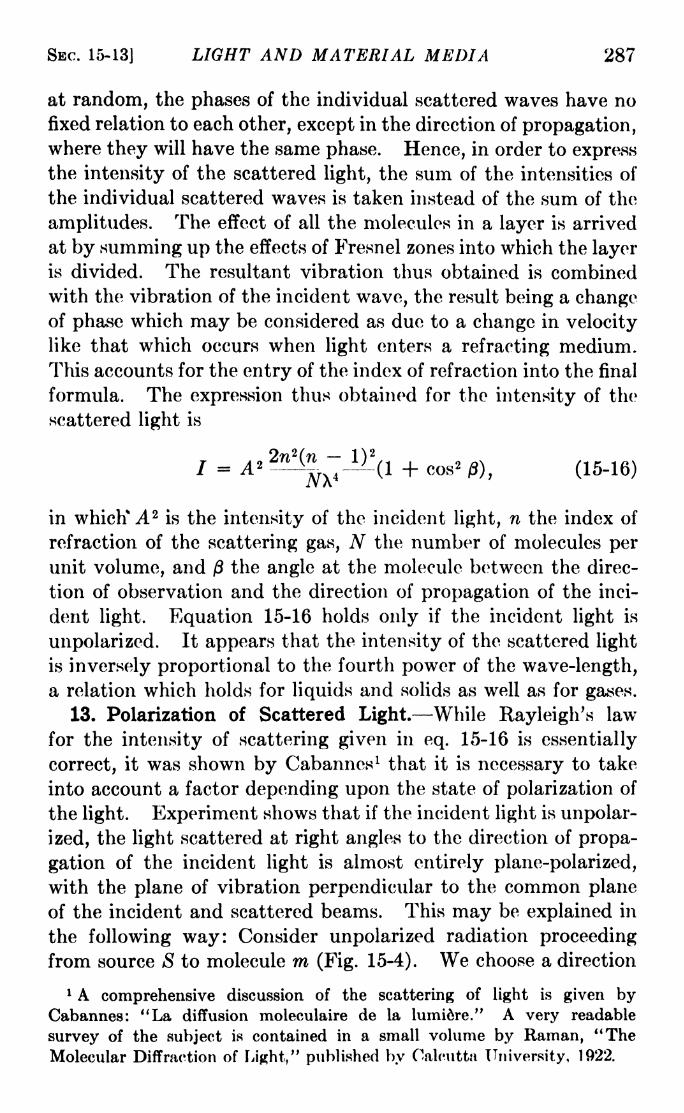
SEC. 15-13] LIGHT AND MATERIAL MEDIA 287
at random, the phases of the individual scattered waves have no
fixed relation to each other, except in the direction of propagation,where they will have the same phase. Hence, in order to expressthe intensity of the scattered light, the sum of the intensities of
the individual scattered waves is taken instead of the sum of the
amplitudes. The effect of all the molecules in a layer is arrived
at by summing up the effects of Fresnel zones into which the layeris divided. The resultant vibration thus obtained is combined
with the vibration of the incident wave, the result being a changeof phase which may be considered as due to a change in velocity
like that which occurs when light enters a refracting medium.
This accounts for the entry of the index of refraction into the final
formula. The expression thus obtained for the intensity of the
scattered light is
(1 + cos* 0, (15-16)
in which* A 2is the intensity of the incident light, n the index of
refraction of the scattering gas, N the number of molecules per
unit volume, and ft the angle at the molecule between the direc-
tion of observation and the direction of propagation of the inci-
dent light. Equation 15-16 holds only if the incident light is
unpolarized. It appears that the intensity of the scattered light
is inversely proportional to the fourth power of the wave-length,a relation which holds for liquids and solids as well as for gases.
13. Polarization of Scattered Light. While Rayleigh's law
for the intensity of scattering given in eq. 15-16 is essentially
correct, it was shown by Cabanncs 1 that it is necessary to take
into account a factor depending upon the state of polarization of
the light. Experiment shows that if the incident light is unpolar-
ized, the light scattered at right angles to the direction of propa-
gation of the incident light is almost entirely plane-polarized,
with the plane of vibration perpendicular to the common plane
of the incident and scattered beams. This may be explained in
the following way: Consider unpolarized radiation proceeding
from source S to molecule ra (Fig. 15-4). We choose a direction
1 A comprehensive discussion of the scattering of light is given byCabannes: "La diffusion moleculaire de la lumiere." A very readable
survey of the subject is contained in a small volume by Raman, "TheMolecular Diffraction of Light," published by Calcutta University, 1922.

288 LIGHT: PRINCIPLES AND EXPERIMENTS [CHAP. XV
S' perpendicular to Sm in which the scattered light is to be
observed. In accordance with the usual treatment of problemsin polarization, the unpolarized beam is considered to be resolved
into two components of vibration, one perpendicular to the plane
SmS', the other in that plane. The direction of vibration of the
second of these components is the same as the direction of propa-
gation mS' of the scattered beam under observation and thus
will contribute nothing to the light at S'. The light at S' should
therefore be completely plane polarized with its direction of
vibration perpendicular to the plane SmS'. The argument holds
for any point of observation on a plane, containing mSr
,to which
Sm is normal. At points of observation as S" not in this plane,
S" S'
Fi<5. 15-4.
the light should be partially polarized. Actual experimentsshow that the light scattered in directions perpendicular to the
direction of propagation of the incident light is not completely
polarized, for reasons which will be discussed later. The use of
a double image prism such as a Wollaston reveals a strong com-
ponent of vibration perpendicular to the plane of S and S' and a
weak component parallel to it.1 Cabannes finds that the inten-
sity of scattering is represented more closely if the right-hand
side of eq. 15-16 is multiplied by a factor
6 - lp
where p is the ratio of the weak (parallel) to the strong (per-
pendicular) component of polarization.
The existence of some unpolarized scattered radiation in a
direction at right-angles to the direction of propagation of the
incident beam is believed to be because some of the molecules are
1 It should not be assumed that this means the presence of two plane-
polarized beams, one perpendicular and one parallel to the mutual plane of
propagation, but rather that the scattered light is a mixture of plane-
polarized and ordinary light.

SBC. 15-14] LIGHT AND MATERIAL MEDIA 289
anisotropic. This term may be explained in the following manner.
Suppose a molecule to consist of three atoms, one with a positive
charge and two with negative charges, as in the case of carbon
dioxide. As long as the geometrical center of the double negative
charge coincides with the position of the positive, the molecule
has no electric moment, but if this coincidence does not exist, the
molecule is said to have an electric dipole moment. Also, if
the centers of electrical charge do coincide, the imposition of an
external electric field will cause a relative displacement of the
charges, resulting in an induced dipole. We may consider the
vibration of these induced dipoles to be the origin of the scattered
radiation. Since the molecules are oriented at random, the vibra-
tions of many of them will be at angles with the direction of
vibration of the light incident upon them. Such molecules are
said to be optically anisotropic, and their contribution to the
scattering is responsible for that part of the light which is
uupolarized.
Accurate measurements of the intensity and state of polariza-
tion of the light scattered by gases are extremely difficult. Not
only is its intensity a minute fraction of the incident light, but
it is often completely masked by the greater scattering from dust
particles. It is also difficult to get rid of multiple reflections in
the apparatus.l In much of the earlier work it is probable that
improper collimation of the incident light gave spurious results.
In accounting for the phenomenon of scattering in the atmospherestill other disturbing factors enter, such as the presence of a
certain amount of light scattered by the earth's surface, and
secondary scattering by the atmosphere. At the same time,
scattering is of considerable importance, since in some details
it depends upon molecular structure, and thus offers a means
of investigating that structure. Also, as is evident from eq.
15-16, it provides a method of determining N, the number of
molecules per unit volume, and, from it, calculating the Avo-
gadro number.
14. Fluorescence. While irradiated with light, many sub-
stances emit in all directions some of the energy of radiation
which they absorb, the color of the light emitted by these sub-
1 See an article by R. J. Strutt (Rayleigh the Younger), Proceedings of
the Royal Soc. (London), 95, 155, 1918.

290 LIGHT: PRINCIPLES AND EXPERIMENTS [CHAP. XV
stances, which are said to exhibit the property of fluorescence,
depending upon the substance and not upon the wave-length of
the incident light. Radiation of short wave-length, such as
ultraviolet light or x-rays, is particularly effective in producingfluorescence. The term owes its origin to the fact that the effect
was first noticed in fluorspar, which emits a blue light whenirradiated with sunlight.
Among other common substances which fluoresce with a blue
light are: paraffine wax, kerosene, benzene, some lubricating oils,
an aqueous solution of aesculin, and an aqueous solution of
quinine sulphate with a few drops of sulphuric acid added. Asolution of chlorophyll in alcohol shows red fluorescence. Fluores-
cene in solution shows yellow green, as does also uranium glass.
When irradiated with x-rays or cathode rays, most glasses
fluoresce, the color depending on the kind of glass. Ultraviolet
light causes the cornea and lens of the eye and the teeth to
fluoresce strongly, and, in smaller amount, the hair and nails also,
the strength of the effect appearing to depend on personal char-
acteristics, such as pigmentation. It has been observed that after
passing through a solution which fluoresces, the light exhibits
reduced power of exciting the same fluorescence, because of
absorption of the exciting light. Thus a weak light falling upon a
solution excites marked fluorescence only in the layer it first
strikes.
The fluorescent light is not of a single wave-length but a band
with a pronounced maximum of intensity. It was formerly
believed that the wave-lengths emitted were always longer than
those of the radiation effective in producing the fluorescence, a
conclusion reached by Stokes and known as Stokes' law. Morerecent investigations have shown that while Stokes' law is
generally obeyed, the wave-length of maximum intensity of
fluorescence is independent of the wave-length of the exciting
light. The intensity of the fluorescence of any solution also
depends upon the character of the solvent.
15. Polarization of Fluorescence. It has been found that
fluorescence of solutions is polarized. The degree of polarization
in some cases depends upon the concentration and the tempera-ture. In general, the more viscous the solvent, the more strongly
is the fluorescence polarized, probably because of the tendency of
the solvent to hold the molecules in a fixed orientation.

SEC. 15-17] LIGHT AND MATERIAL MEDIA 291
In the case of isotropic substances, the polarization also
depends upon the obliquity of emission. Some fluorescent
crystals also exhibit peculiarities of polarization. No such
degree of polarization exists in fluorescence, however, as in
scattering of light, where almost complete plane polarization
exists, the vibrations being at right angles to the incident beam.
16. Phosphorescence. The term fluorescence is used whenthe process of emission goes on while the substance is beingirradiated. Substances which continue to emit light for sometime after the exciting light is removed are termed phosphorescent.The emission continues for different periods of time, depending on
the substance and sometimes on temperature changes. Calcium
sulphide continues its phosphorescence for many hours after the
exciting radiation is removed, and is for this reason used as an
ingredient in phosphorescent paint.
Phosphorescence and fluorescence are difficult to distinguish,
since the former persists in some cases only for an extremely small
fraction of a second after the exciting light is removed. Actually,all solid fluorescent substances are phosphorescent. It is cus-
tomary to limit the use of the term phosphorescence to the prop-
erty exhibited by certain crystalline substances which contain
impurities in the form of metallic particles. It is these particles
which are responsible for the phosphorescence. In all other
cases of so-called phosphorescence a better term is delayed, or
persistent, fluorescence.
Little is known of what is actually going on in a solid which
absorbs light and fluoresces. It is believed that a photochemical
process takes place owing to the absorption of light energy, the
process later reversing with the accompaniment of light emission.
17. Fluorescence in Gases. Rayleigh the younger has
observed that the D-lines of sodium (5890 and 5896 angstroms)
are emitted from a glass container of sodium vapor when it is
irradiated by the light of the zinc line at 3303 angstroms. This
is a case of true fluorescence, and is explained by the quantum
theory of spectra in the following manner.
The D-lines of sodium constitute the first member of the
principal series, of which the second member is the doublet
3302.3 and 3302.9. Upon being irradiated by light of that
wave-length (of the zinc spectrum in the case quoted) the atoms
of the sodium vapor absorb energy of radiation, thereupon under-
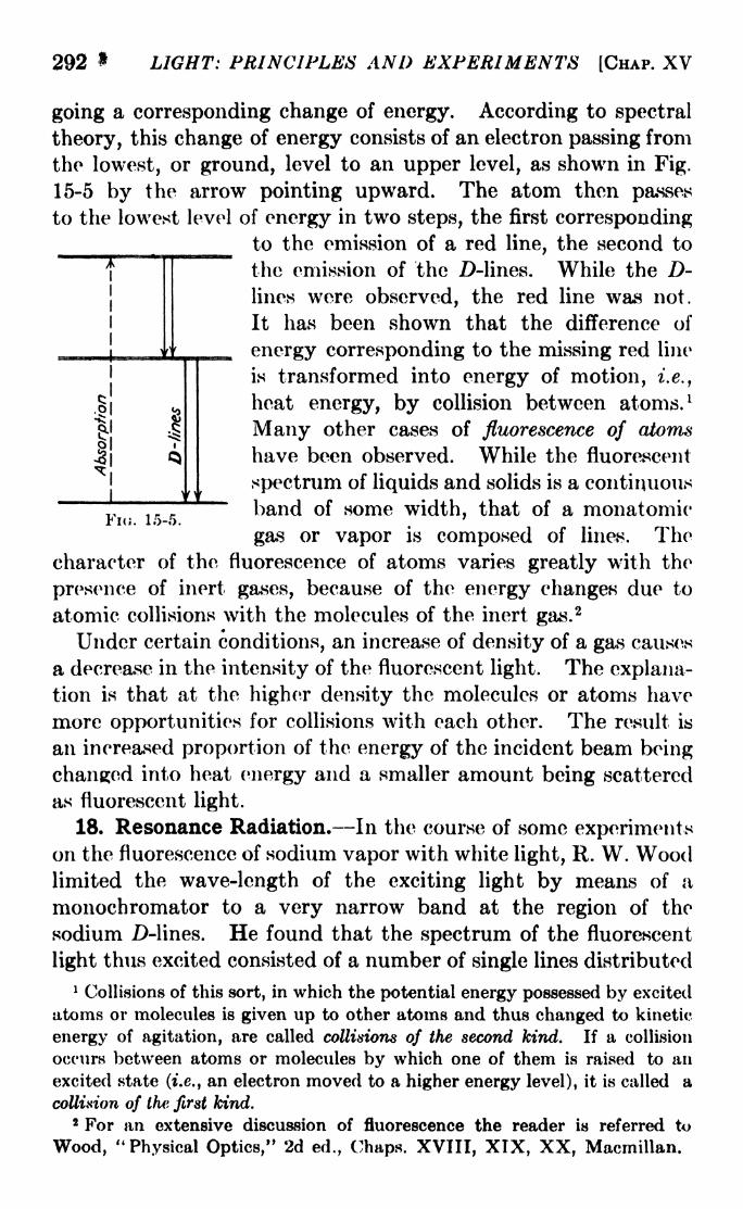
292 * LIGHT: PRINCIPLES AND EXPERIMENTS [CHAP. XV
^*r
I
I 1
e-1
li
Fni. 15-5.
going a corresponding change of energy. According to spectral
theory, this change of energy consists of an electron passing from
the lowest, or ground, level to an upper level, as shown in Fig.
15-5 by the arrow pointing upward. The atom then passes
to the lowest level of energy in two steps, the first correspondingto the emission of a red line, the second to
the emission of the ZMines. While the D-lines were observed, the red line was not.
It has been shown that the difference of
_ energy corresponding to the missing red line
is transformed into energy of motion, i.e.,
heat energy, by collision between atoms. 1
Many other cases of fluorescence of atoms
have been observed. While the fluorescent
spectrum of liquids and solids is a continuous"~
band of some width, that of a monatomic
gas or vapor is composed of lines. Thecharacter of the fluorescence of atoms varies greatly with the
presence of inert gases, because of the energy changes due to
atomic collisions with the molecules of the inert gas.2
Under certain conditions, an increase of density of a gas causes
a decrease in the intensity of the fluorescent light. The explana-tion is that at the higher density the molecules or atoms have
more opportunities for collisions with each other. The result is
an increased proportion of the energy of the incident beam being
changed into heat energy and a smaller amount being scattered
as fluorescent light.
18. Resonance Radiation. In the course of some experimentson the fluorescence of sodium vapor with white light, R. W. Woodlimited the wave-length of the exciting light by means of a
monochromator to a very narrow band at the region of the
sodium D-lines. He found that the spectrum of the fluorescent
light thus excited consisted of a number of single lines distributed
1 Collisions of this sort, in which the potential energy possessed by excited
atoms or molecules is given up to other atoms and thus changed to kinetic
energy of agitation, are called collisions of the second kind. If a collision
occurs between atoms or molecules by which one of them is raised to an
excited state (i.e., an electron moved to a higher energy level), it is called a
collision of the first kind.2 For an extensive discussion of fluorescence the reader is referred to
Wood, "Physical Optics," 2d ed., Chaps. XVIII, XIX, XX, Macmillan.

SEC. 15-19] LIGHT AND MATERIAL MEDIA 293
throughout the spectrum. The wave-length distribution
changed with slight alterations in the exact wave-length rangeallowed to pass from the incident light by the monochromator.The fluorescence obtained in this manner he called resonance,
radiation, and the spectra, resonance spectra. Resonance radia-
tion may be obtained by the use of an irradiating source consistingof a single line of a metallic spectrum, and also with other vaporsthan that of sodium. ^ <
19. Raman Effect.-(ln. 1928, Raman, after several years of
investigation of light scattering, discovered that when a trans-
Fio. 15-6. Raman effect in carbon tetrachloride. Above, the spectrum of the
incident light. Below, the spectrum of the scattered light, showing the Ramanlines on either side of the stronger lines due to ordinary scattering. (FromRaman and Kri&hnan, Proceedings of the Royal Society of London, 122, 23, 1929.)
parent liquid is irradiated with monochromatic light from a
strong source the spectrum of the scattered light contains, in
addition to the exciting line of frequency v, several weaker
lines on either side, whose frequencies are given by v + Av.
Later, the same effect was discovered in solids and gases. Thedifferences AJ> are independent of the frequency of the original
radiation and depend only on the nature of the scattering
medium. The appearance of the displaced lines, known as the
Ramaneffectfas
illustrated in Pig. 15-6. As is evident, it is not
necessary td use strictly monochromatic light provided the
spectrum of the source contains only relatively few lines.
The lines displaced to thejed are oftenjsferred to as StokesJLnes
and those to the violet as anti-Stokeslineg.)
This custom arose
from the hypothesis proposed by. Stokes many years earlier, and
referred to in Sec. 15-14, that secondary radiation such as

294 LIGHT: PRINCIPLES AND EXPERIMENTS [CHAP. XV
fluorescence was always of longer wave-length than the incident
light. In the Raman effect the anti-Stokes lines are invariablyfainter than the Stokes lines.
The displaced lines are so much fainter than the lines of the
exciting radiation that very long exposures are necessary to
photograph them. ^A simple type of apparatus is shown in Fig.
15-7. The source M is usually a quartz mercury arc of great
intensity. The liquid to be examined is contained in a horn-
shaped tube R, shielded from extraneous light and surrounded
by a water cooler W, the small end of the horn being blackened
and curved so that light reflected internally will be directed
away from the larger end at which the observations are made.
M
Fio. 15-7.- A form of Raman tube. j
The discovery of Raman was not entirely unexpected. In
1923, A. H. Compton, while examining the spectra of x-rays
scattered by a solid, discovered in the spectrum of the scattered
radiation a line of smaller freqyency than that ofc^the incident
x-rays. Also, in the same yearjdt had been predicted by Smekal 1
that in addition to light of the same frequency as the incident
radiation thorc should be present in the spectrum of ordinary
scattered radiation lines with combination frequencies v vm,
where vm is a characteristic frequency of absorption of the
molecule, to be observed in the absorption spectrum in the infra-
red. Smekal's suggestion was that when a photon of energyhv is incident on a molecule there will take place an exchange of
energy in which the photon will either be augmented by, or
have subtracted from it, an amount of energy hvm . In 1924, a
similar prediction was made by Kramers2upon the basis of a
new quantum theory of dispersion (Sec. 15-8), which was pub-
1 Naturwssenschaft, 11, 873, 1923.
2Nature, 113, 673, 1924.
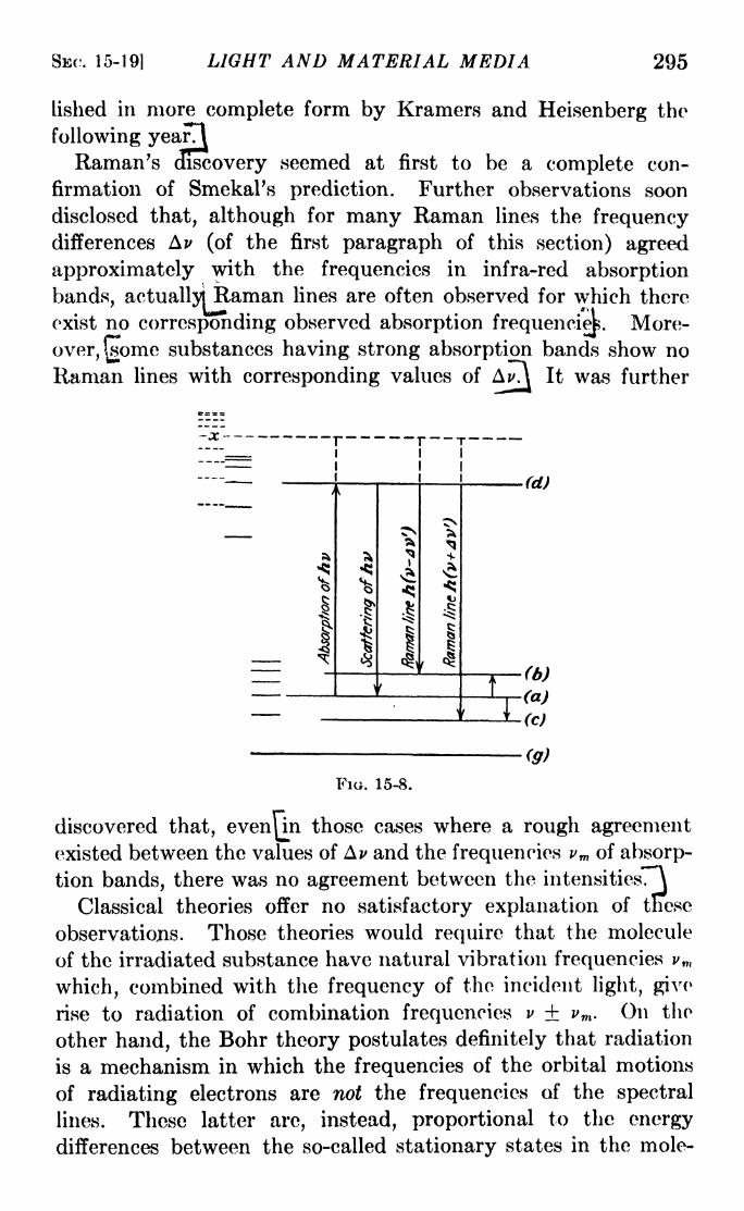
SEC. 15-19] LIGHT AND MATERIAL MEDIA 295
lished in more complete form by Kramers and Heisenberg the
following yearTI
Raman's cEscovery seemed at first to be a complete con-
firmation of SmekaPs prediction. Further observations soon
disclosed that, although for many Raman lines the frequencydifferences Av (of the first paragraph of this section) agreed
approximately with the frequencies in infra-red absorption
bands, actually! Raman lines are often observed for which thereAMMft ' X
4
exist no corresponding observed absorption frequenciep. More-
over, (jsome substances having strong absorption bands show no
Raman lines with corresponding values of AJvt It was further
(g)
FIG. 15-8.
discovered that, evenj^inthose cases where a rough agreement
existed between the values of AJ> and the frequencies vm of absorp-
tion bands, there was no agreement between the intensitiesTA
Classical theories offer no satisfactory explanation of tnese
observations. Those theories would require that the molecule
of the irradiated substance have natural vibration frequencies vm
which, combined with the frequency of the incident light, give
rise to radiation of combination frequencies v vm . On the
other hand, the Bohr theory postulates definitely that radiation
is a mechanism in which the frequencies of the orbital motions
of radiating electrons are not the frequencies of the spectral
lines. These latter are, instead, proportional to the energy
differences between the so-called stationary states in the mole-

296 LIGHT: PRINCIPLES AND EXPERIMENTS [CHAP. XV
cule. Moreover, in the Raman effect the intensities of the
lines displaced toward the red are greater than those displaced
toward the violet, as shown in Fig. 15-6, an effect also not in
accordance with the classical concept of combination frequencies.
The explanation of the Raman effect is really to be found as an
integral part of the quantum theory of dispersion gind maybereduced to the following simple terms.")
Consider a molecule in the energy state indicated by a vibra-
tional energy level a, Fig. 15-8, to be struck by a photon of
energy hv, and raised to an energy state represented by level d,
for which the transitions d > b or d c are not possible accordingto the selection rules of theory. Then Raman radiation is
possible only if there exist in the molecule higher energy levels,
represented by the group of horizontal dotted lines x, between
which and the two levels 6 and c transitions are possible. It is
to be understood that 6 and c likewise each represents a familyof levels, so that groups of Raman lines will be observed. Also,
the incident quantum may be that corresponding to any line
emitted by the irradiating source.
There are three possible ways in which radiation may take
place. Either the molecule, upon being struck by a photon of
energy hv, may scatter the same quantum, contributing to the
intensity of a spectral line of the same wave-length as that of
the incident photon (ordinary scattered light) ;it may reradiate
a quantum & v\ = hv (Ea Eb) where Ea Eb is the difference
of energy hAv between levels a and 6, contributing thereby to
the intensity of a Raman line displaced toward the red; or it
may reradiate a quantum hv2 hv -f- (Ec Ea), contributing
to the intensity of a Raman line displaced toward the
violet. The level a represents only one of a number of possible
enerjjrstates in which the molecule may be at the time it is
struck by the photon. This bears upon the question of the
intensities of the Stokes and anti-Stokes lines, and the dependenceof these intensities upon the transition probabilities. If, as
usually happens, the molecule is in a low energy state, represent-
ing a relatively small total energy of the molecule, then the
probability is enhanced that it will reradiate with energy
h(v-
If, on the other hand, the original level a is relatively high (a

SEC. 15-19] LIGHT AND MATERIAL MEDIA 297
more unusual circumstance for substances under ordinary
temperature conditions), the probability is enhanced that it
will reradiate with energy h(v + AJ>). Hence it is apparentthat there is no dependence of the Raman line intensities upon the
probability of transitions between levels a and b or a and c, but
only on the probability of the transitions a * x and x b or
x > c.
{inthe complete theory of the Raman effect/^of which the
foregoing is only 'a~ 'C'dTTfteTfised and oversimplified account^ it is
supposed that the transitions to and from the level represented
by the dotted lines x are not real but virtual. This meansthat the initial photon of energy hv does not actually raise the
molecular energy to the level x. If scattering takes place, the
upper level is one such as d from which an actual transition
d a may occur. If Raman lines appear, the dual energy
change a > x and x > 6 theoretically represented as responsible
for each Stokes line really consists of only a single transition,1
the same being true for the anti-Stokes lines. This theoretical
interpretation agrees with the fact mentioned earlier, that in
some cases no infrared absorption bands are found at frequencies
corresponding to the values of Ai>. Not only do the differences
of frequency Av appear in the Raman spectrum, but theory holds
that the Raman lines cannot occur unless energy levels such as
a and b actually existjIn this manner the ftlaman effect
offers an experimental method of finding those characteristic
energy states of the molecule, even though there can be found
no absorption bands in the spectrum to correspond to themjA superficial comparison or the Raman effect with fluorescence
may leave the reader in doubt as to the difference between them,since in both cases the substance radiates energy correspondingto frequencies other than those of the irradiating light. In the
case of fluorescence the reradiated energy is of a frequencywhich the fluorescing substance is able to absorb, with no depend-ence upon the frequency of the incident light, while in the
Raman effect there is a fixed frequency difference Ai> between
the displaced radiation and the incident radiation, no matter
what the frequency of the latter may be. 2
1 There will, accordingly, be a modification of the usual selection rules,
given in Sec. 14-17.2 A full discussion of experimental work in the Raman effect will be found
in R. W. Wood, "Physical Optics," Mapmillnn, 1934.
298 LIGHT: PRINCIPLES AND EXPERIMENTS [CHAP. XV
One important difference between ordinary and modified
scattered radiation, i.e., between that which gives rise to the
undisplaced spectrum line and that which causes the Ramanlines, is in the phase relationship which the two bear to the
incident light. In ordinary scattering there is a definite phaserelation between the incident and scattered radiation. In the
Raman effect the radiations from different molecules have phasedifferences which vary from one molecule to the next, and also
different states of polarization. For this reason, ordinary
scattering is called coherent, and the Raman, incoherent sc&tterine
20. The Photoelectric Effect. For the most part the phenom-ena described in this chapter illustrate the importance of the
quantum theory of radiation whenever the interaction of that
radiation with matter is involved. The usefulness of that theorywill be still more fully brought out in the following chapter.
Historically, however, its first great success in explaining the
interaction of light and matter was in connection with a phenom-enon which is not strictly optical, but which involves the effect
of light, called the photoelectric effect. It is that whenever a
metallic surface is irradiated by visible or ultraviolet light,
x-rays, or -y-rays from radioactive substances, electrons, are
ejected from the surface. The effect is much greater for some
metals, such as sodium, potassium, and cesium, than for others,
these metals being largely used, accordingly, in the construction
of the modern photoelectric cell. It is found that the velocity
possessed by an ejected electron depends, not upon the intensity
of the radiation, but upon its frequency. This result cannot be
explained on the basis of classical theory, since, if we call the
kinetic energy of the electron )^wv2,there is every reason to
believe that more intense radiation, possessing greater energy,
might communicate more energy to the electron and thus give
it a greater velocity than does weaker radiation.
The true explanation was given by Einstein in 1905. By an
extension of Planck's hypothesis, that the energy of the "oscil-
lators" in a black-body radiation consists of integral amounts of
some indivisible unit of energy e (see Sec. 14-13), proportional
to hv. It follows inescapably from that theory that the energy
of radiation must itself be quantized.
Einstein carried this result still farther by the hypothesis that
the energy of each quantum of radiation is not, as required by
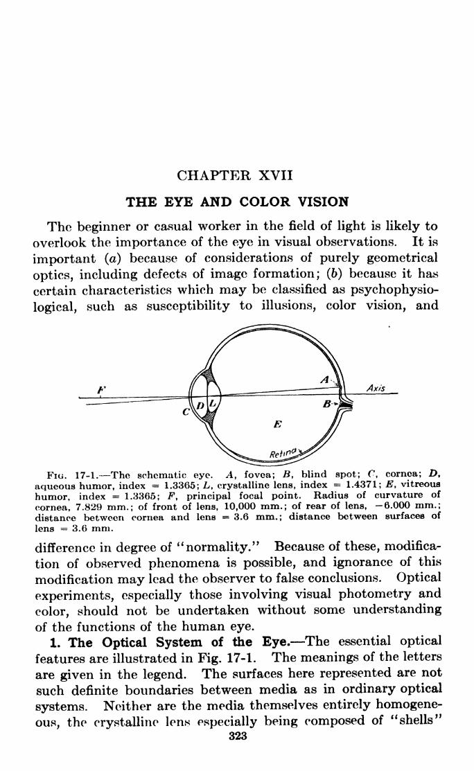
CHAPTER XVII
THE EYE AND COLOR VISION
The beginner or casual worker in the field of light is likely to
overlook the importance of the eye in visual observations. It is
important (a) because of considerations of purely geometrical
optics, including defects of image formation; (6) because it has
certain characteristics which may be classified as psychophysio-
logical, such as susceptibility to illusions, color vision, and
Fi. 17-1. The schematic eye. A, fovea; B, blind spot; C, cornea; D,
aqueous humor, index = 1.3365; L, crystalline lens, index = 1.4371; E, vitreous
humor, index = 1.3365; F, principal focal point. Radius of curvature of
cornea, 7.829 mm.; of front of lens, 10,000 mm.; of rear of lens, 6.000 mm.;distance between cornea and lens = 3.6 mm.; distance between surfaces of
lens = 3.6 mm.
difference in degree of ''normality." Because of these, modifica-
tion of observed phenomena is possible, and ignorance of this
modification may lead the observer to false conclusions. Optical
experiments, especially those involving visual photometry and
color, should not be undertaken without some understanding
of the functions of the human eye.
1. The Optical System of the Eye. The essential optical
features are illustrated in Fig. 17-1. The meanings of the letters
are given in the legend. The surfaces here represented are not
such definite boundaries between media as in ordinary optical
systems. Neither are the media themselves entirely homogene-
ous, the crystalline lens especially being composed of "shells"
323
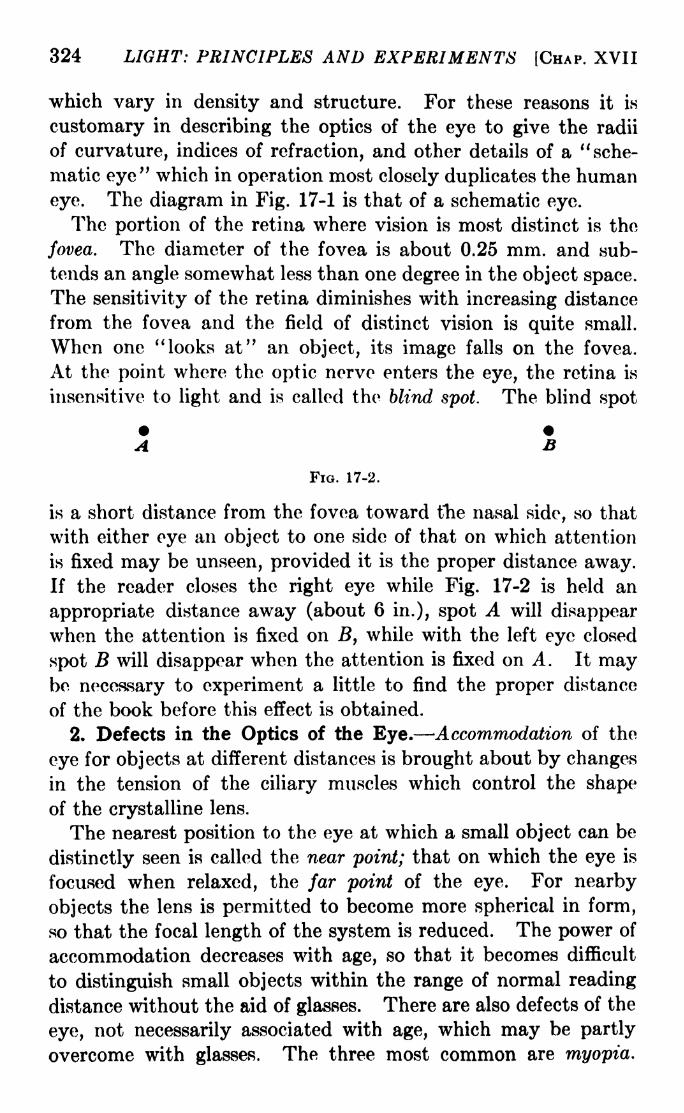
324 LIGHT: PRINCIPLES AND EXPERIMENTS [CHAP. XVII
which vary in density and structure. For these reasons it is
customary in describing the optics of the eye to give the radii
of curvature, indices of refraction, and other details of a "sche-
matic eye" which in operation most closely duplicates the human
eye. The diagram in Fig. 17-1 is that of a schematic eye.
The portion of the retina where vision is most distinct is the
fovea. The diameter of the fovea is about 0.25 mm. and sub-
tends an angle somewhat less than one degree in the object space.
The sensitivity of the retina diminishes with increasing distance
from the fovea and the field of distinct vision is quite small.
When one " looks at" an object, its image falls on the fovea.
At the point where the optic nerve enters the eye, the retina is
insensitive to light and is called the blind spot. The blind spot
B
FIG. 17-2.
is a short distance from the fovea toward the nasal side, so that
with either eye an object to one side of that on which attention
is fixed may be unseen, provided it is the proper distance away.If the reader closes the right eye while Fig. 17-2 is held an
appropriate distance away (about 6 in.), spot A will disappearwhen the attention is fixed on B, while with the left eye closed
spot B will disappear when the attention is fixed on A. It maybe necessary to experiment a little to find the proper distance
of the book before this effect is obtained.
2. Defects in the Optics of the Eye. Accommodation of the
eye for objects at different distances is brought about by changesin the tension of the ciliary muscles which control the shapeof the crystalline lens.
The nearest position to the eye at which a small object can be
distinctly seen is called the near point; that on which the eye is
focused when relaxed, the far point of the eye. For nearby
objects the lens is permitted to become more spherical in form,
so that the focal length of the system is reduced. The power of
accommodation decreases with age, so that it becomes difficult
to distinguish small objects within the range of normal reading
distance without the aid of glasses. There are also defects of the
eye, not necessarily associated with age, which may be partly
overcome with glasses. The three most common are myopia.

SEC. 17-4] THE EYE AND COLOR VISION 325
hyperopia, and astigmatism. The first two are the result of
abnormalities in the distance from the front of the eye to the
retina, while the last is caused by lack of sphericity of the refract-
ing surfaces, principally the cornea. An eye in which light
from a distant object is focused exactly at the retina whenaccommodation is entirely relaxed is said to be emmetropic.
Eyes which are myopic or hyperopic are said to be ametropic.
These conditions are illustrated in Fig. 17-3. That the eye also
suffers from barrel-shaped distortion
can be shown by looking at a grid of
perpendicular lines. The pattern will <a )
appear convex if held close to the
oye.
3. Binocular Vision. Ability to
bring the image of an object simul-
taneously on the fovea of each eye is
called binocular vision. The pupils of
the eyes in humans are separated bya distance of a few inches, so that
with one eye the superposition of
objects along the line of sight is not
quite the same as it is with the other.
The resulting slight difference in the
images formed on the fovea of each
eye enables one to determine depth in the object, or, in
other words, to perceive space in three dimensions. Otherfactors enter into the situation, especially when illumination is
poor, .the distance great, or the scene unfamiliar. A personhaving only one eye capable of seeing may make use "of othercriteria of distance, such as the relative size of objects, their
relative displacement in the case of motion, or a recollection of
past experiences.
4. The Stereoscope. In an ordinary photograph, objects at
different distances are all projected on a single plane, so that the
picture itself gives no effect of depth or relative distance and
dependence must be made upon experience and judgment in
forming a mental picture of the depth of the scene. To enhancethe effect of depth, the stereoscope is used. Two photographsare taken, with a slight lateral displacement of the camera, or
with a stereoscopic camera which takes two pictures at the same
FIG. 17-3.

326 LIGHT: PRINCIPLES AND EXPERIMENTS [CHAP. XVII
B
time with twin lens systems separated by a few inches. The
prints are then mounted side by side and looked at through a
stereoscope, one form of which is
illustrated in Fig. 17-4. With
a little practice some personsare able to achieve stereoscopic
vision of a pair of photographswithout aid, the process con-
sisting of seeing each photo-
graph separately, the left-hand
picture with the left eye and
the right-hand picture with the
right eye, and bringing the twointo coincidence.
The principles of binocular vision are made use of in the con-
struction of microscopes and telescopes, duplex optical systems
being set side by side in the instrument. Some so-called binocular
microscopes are not stereoscopic in the true sense, having merelytwo oculars both of which receive the image formed by the
objective, through a mirror or prism system. The purpose in this
case is to enable the observer to use both eyes and relieve
eyestrain.
Fio. 17-4.- A form of stereoscope.
(a)
Fio. 17-5. Optical illusions.
5. Optical Illusions. Ocular experience with the common-
place often leads one astray in viewing the uncommon. Ordi-
nary optical illusions are illustrated in Fig. 17-5, in which a, 6,

SEC. 17-71 THE EYE AND COLOR VISION 327
and c are geometrical-optical, and d is due to irradiation. In d
the white center circle looks larger than the black, although it is
exactly the same size. Irradiation is sometimes a source of
error in the measurement of spectral line positions, especially in
absorption spectra. When the background between the lines
is more dense than that on either side there is a tendency to
estimate the lines to be farther apart than their positions shown
by a purely objective microphotometric measurement.
6. The Contrast Sensitivity of the Eye. While an extensive
treatment of the limitations and capabilities of the human eyewould carry us beyond the field of physics and into those of
psychology and physiology,1 certain characteristics of vision
which are important in experimental optics will be discussed
briefly in this and the following sections.
The eye is designed to afford satisfactory vision over as wide
a range of conditions as possible, and for this reason it is not a
good judge of differences of brightness or intensity except under
the most restricted conditions. The ability to distinguish
between areas of different brightness is made use of in photom-
etry. Most photometers are arranged so that the two fields to
be compared are seen at the same time, one, the standard, being
capable of fairly rapid variation of brightness. It is importantthat the two areas be arranged so that the effect of contour on
relative brightness is reduced to a minimum. Ordinarily one
of the areas is a small square or circle at the center of a like
figure of considerably greater area. The contrast sensitivity maybe measured by adjusting the brightness of the center spot so
that it is barely different from that of the larger area. If the
difference of brightness is A#, and the brightness of the larger
area B, then AB/B is the contrast sensitivity. It is practically
constant for brightness above about 1 candle per square meter,
but it increases very rapidly as the brightness decreases.
7. Flicker Sensitivity. Persistence of Vision. The sensation
in the retina does not cease at once when the stimulus is removed,and in consequence the intermittency of a flickering light will
not be detected, provided the flicker is rapid enough. With a
1See, for instance, Helmholtz, "Physiological Optics," English trans-
lation by J. P. C. Southall, published by the Optical Society of America;also Troland, "Psycho-physiology," Van Nostrand; Parsons, "Introduction
to the Study of Colour Vision," Cambridge University Press; and Collins,
"Colour Blindness," Harcourt, Brace.

328 LIGHT: PRINCIPLES AND EXPERIMENTS [CHAP. XVII
field brightness of about 1 candle per square meter the critical
frequency beyond which no flicker may be detected is about
30 times per second. The critical frequency is a function of the
alternation in brightness.
A flicker method is often used for the comparison of photo-
graphs in which slight changes are to be sought, as in photographsof areas of the sky, taken at different times. In order to detect
the presence of stellar objects whose proper motion (motionacross the line of sight) is great compared to those of the general
background of stars, the two photographs are arranged so that
by shifting a mirror back and forth, first one and then the other
may be seen in the field of a microscope. If any stellar object
is in different positions in the two photographs, its displacementrelative to the general background may be detected and, with a
micrometer eyepiece, measured.
The flicker photometer may be used for the comparison of the
intensities of two sources between which there is a considerable
difference of color. The light of one source is reflected to the
eye from a stationary white screen Si. The light of the other
source is reflected from the surface of a rotating disk 82, with
white vanes. This disk is so placed that Si may be seen throughits open spaces, which have the same total area as the vanes.
The disk may be rotated at a speed such that while the colors
blend, the illuminations do not. The sense of flicker which is
experienced when the two sources are not of the same intensity
disappears when their distances arc adjusted so as to equalize
the illuminations. The flicker photometer should be used under
carefully controlled conditions, and only when the intensities are
sufficiently high so that there is no Purkinje effect (see Sec. 17-8).
Flicker methods are also used to reduce the intensity of a
source, the light usually being passed through a disk from which
sectors have been cut. In this case the rate at which the light
is alternated by reason of the interposition of the opaque parts
of the disk must be greater than the critical frequency mentioned
above. It has been proved that the apparent brightness of an
object viewed through such a rotating disk is proportional to the
ratio of the angular aperture of the open to the opaque sectors.
This is known as Talbot's law.
8. Spectral Sensitivity. The sensitivity of the normal eye
as a function of wave-length is shown by the solid curve in Fig. 17-6
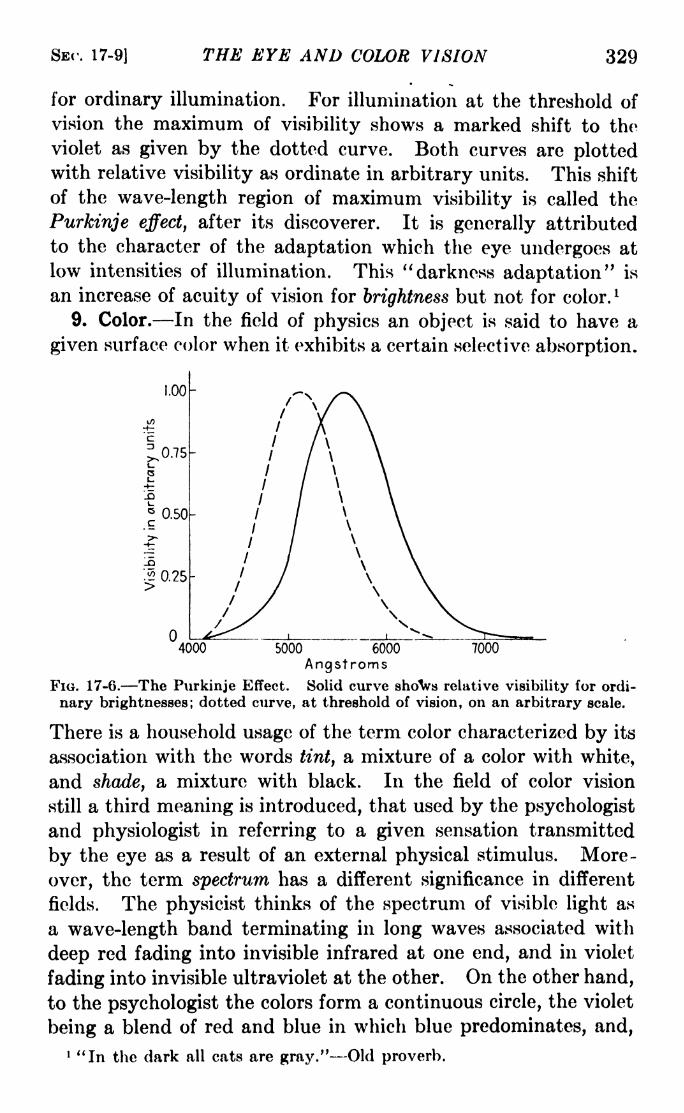
SEC. 17-9] THE EYE AND COLOR VISION 329
for ordinary illumination. For illumination at the threshold of
vision the maximum of visibility shows a marked shift to the
violet as given by the dotted curve. Both curves are plottedwith relative visibility as ordinate in arbitrary units. This shift
of the wave-length region of maximum visibility is called the
Purkinje effect, after its discoverer. It is generally attributed
to the character of the adaptation which the eye undergoes at
low intensities of illumination. This "darkness adaptation" is
an increase of acuity of vision for brightness but not for color. l
9. Color. In the field of physics an object is said to have a
given surface color when it exhibits a certain selective absorption.
4000 70005000 6000
AngstromsFIG. 17-6. The Purkinje Effect. Solid curve shoVs relative visibility for ordi-
nary brightnesses; dotted curve, at threshold of vision, on an arbitrary scale.
There is a household usage of the term color characterized by its
association with the words tint, a mixture of a color with white,
and shade, a mixture with black. In the field of color vision
still a third meaning is introduced, that used by the psychologist
and physiologist in referring to a given sensation transmitted
by the eye as a result of an external physical stimulus. More-
over, the term spectrum has a different significance in different
fields. The physicist thinks of the spectrum of visible light as
a wave-length band terminating in long waves associated with
deep red fading into invisible infrared at one end, and in violet
fading into invisible ultraviolet at the other. On the other hand,
to the psychologist the colors form a continuous circle, the violet
being a blend of red and blue in which blue predominates, and,
1 "In the dark all cats are gray." Old proverb.

330 LIGHT: PRINCIPLES AND EXPERIMENTS [CHAP. XVII
beyond the violet, purple, a "nonspectral" blend of blue and red
in which red predominates once more. 1
The psychological definition of color is perhaps best given in
the following words:2 " Color is the general name for all sensations
arising from the activity of the retina of the eye and its attached
nervous mechanisms, this activity being, in nearly every case
in the normal individual, a specific response to radiant energy of
certain wave-lengths and intensities."
10. Hue. The spectrum is said to be made up of hues.
Four of these, red, yellow, green, and blue, are unique in that
they are not composed of mixtures of others. Orange is con-
sidered as a mixture of red and yellow. Two other blends of
contiguous hues are blue-green and yellow-green. Violet is a
mixture of red and blue with blue predominating; purple, a
nonspectral mixture of red and blue with red predominating.With the addition of black and white, from these nine hues all
colors may be produced. "Hue is that attribute of certain
colors in respect of which they differ characteristically from the
gray of the same brilliance and which permits them to be classed
as reddish, yellowish, greenish, or bluish."
The sensation of white is produced by any color if sufficiently
intense. Hence yellow, which produces relatively the largest
stimulus, is said to contain the greatest amount of white.
11. Saturation. A color is said to be saturated when it is
mixed with the smallest possible quantity of white or black.
According to the preceding section, yellow is less saturated than
the red obtained from the same white-light spectrum. However,if the entire spectrum is reduced in luminosity, the red is said
to become desaturated by mixture with black, while at the same
time the yellow approaches saturation by a reduction of its
1 As a result of the combined planning and research of those whose chief
interest is in the field of colorimetry, the subject of color has been lifted from
the realm of vague concept and discordant terminology to the position of a
well-developed technology with precise techniques. This has come about
largely through the exchange of ideas and deliberations of international
commissions meeting at intervals of several years, and dealing with the
subjects of illumination, color, and spectrophotometry. Several of the
references in the following sections are to reports of these commissions.2 This definition, as well as those of hue, saturation, and brilliance quoted
in following sections, are from the Report of the Committee on Colorimetry
for 1920-1921, Jour. Opt. Soc. Amer., 6, 527.

SEC. 17-13] THE EYE AND COLOR VISION 331
luminosity. "Saturation is that attribute of all colors possessinga hue which determines their degree of difference from a grayof the same brilliance."
12. Brilliance. The term closest to this in meaning in physicsis brightness'or luminosity, but since these have already beenused with objective meaning, the term brilliance will be used to
indicate the relative excitability of the retina for different partsof the spectrum. Thus, the yellow is the most brilliant color
in the spectrum of a white-light source of ordinary intensity.1
"Brilliance is that attribute of any color in respect of which it
may be classed as equivalent to some member of a series of grays
ranging between black and white."
13. Color and the Retina. The retina of the human eye is a
complicated structure composed of many layers, each of a
composite structure. The parts most directly associated in
theory with color vision are the rods and cones. That the rods
and cones play an important part in the mechanism is shown bythe following observed relations. 2
a. In case of congenital absence of both rods and cones, blindness
exists.
6. If the fovea has no rods, that part of the retina suffers from night
blindness, a term describing various degrees of inability to see with low
illumination.
c. Color blindness accompanies a congenital absence of cones.
d. Animals having a predominance of rods (bats, owls, etc.) have good
night vision and poor day vision, while birds, with a predominance of
cones, have the opposite characteristics.
e. Rapidity of adaptation to dark is associated with the extent of
changes which take place in the rods.
The relationships just given support the theory that the rods
are important in brightness vision and the cones in color vision.
All parts of the retina do not have the same degree of sensitivity
to color, which is probably due to the cones becoming relatively
infrequent as the periphery is reached. In normal eyes the
retina is sensitive to yellow over the largest area and to blue
1 It is perhaps worth while to warn against confusion of this distribution
of brilliance with the distribution of radiant energy associated with a
source at a given temperature, as described by Wien's distribution law.
2 These relations have been adapted from Bills, "General Experimental
Psychology," Ixmgmans.

332 LIGHT: PRINCIPLES AND EXPERIMENTS [CHAP. XVII
over one almovst as large, to red over a still smaller area, and to
green over the smallest.
14. Complementary Colors. If two colored lights are mixed,the resulting stimulus matches that of a third, the exact color
of which depends upon the proportions of the mixture. Often in
such cases the match is not perfect, the mixture being less
saturated than the third color. As the spectral separation
(difference of wave-length) of the two colors mixed is increased,
the saturation becomes less. Two colors sufficiently far apartin the spectrum give, when mixed, the sensation of white. Such
colors are called complementary. Table 17-1, of complementary
colors, is due to Helmholtz. 1
Color
Red 6562A
Orange \
6077A
Yellow,Yellow
Yellow
Yellow
Yellow green
5853A5739A5671A5644A5636A
Complementary color
Green blue I 4921 ABlue
i 4897ABlue
j
4851ABlue
I4821A
Indigo blue 4G45A
Indigo blue 461 8AViolet
j4330A and beyond
16. Theories of Color Vision. 2 It is found by experiment that
a color stimulus may be accurately matched by a mixture of
correct amounts of three color stimuli. The first person to makeuse of this as the basis of a mechanistic theory of color vision
seems to have been the versatile genius, Thomas Young. His
postulation of the existence in the human eye of three independ-
ent mechanisms of color perception, each correlated with one
of the three primaries, red, green, and blue, is the basis of what
is now universally known as the Young-Helmholtz theory of
color vision. Equal stimulation of all three mechanisms results
1 A more extended table of complementaries, based on the standard
source for colorimetry, used in place of the so-called white-light source
of earlier research (see Sec. 17-18), is to be found on p. 31 of the "Handbookof Colorimetry," by A. C. Hardy, The Technological Press, 1936. The
values of complementaries listed in this table are those of the dominant
wave-lengths of complementary colors (see item 6, Sec. 17-19).2 For a more extensive treatment see Parsons, "An Introduction to the
Study of Colour Vision," Cambridge University Press.

SBC. 17-15] THE EYE AND COLOR VISION 333
in gray. Black is the absence of any stimulus. The relative
sensitivity of the different mechanisms is illustrated by Fig. 17-7.
The Young-Helmholtz theory accounts for after-images as due
to retinal fatigue, but does not account for the gray after-imageof black nor the black after-image of gray. It does riot account
for contrast, nor for the existence of color-sensitive zones in the
retina. It accounts only partly for color blindness, not providingfor the gray vision of the color blind. On the other hand, the
correspondence between the fundamental postulate of Young and
the experimental facts of the science of colorimetry make the
theory a suitable conveyance for the concepts and nomenclature
of the purely metrical phases of that science.
R
4000 5000 6000" "" "
7000
FIG. 17-7. Relative sensitivity of the red, green, and blue mechanisms of
color perception. The shape of the curves is illustrative only, and conformsto no particular set of data.
The theory of Bering claims the existence in the retina of two
mutually exclusive processes: (a) anabolism, the process bywhich matter is transformed into tissues; and (6) catabolism, the
process by which substance is broken down in the tissue. This
theory recognizes the presence in the retina of three mechanisms
which can be excited in either of these processes. Anabolic
excitation yields the sensations of green, blue, and black; cata-
bolic, red, yellow, and white. This theory explains the phe-nomena of complementary colors, but not the mixture of black
and white to form gray. It accounts only partly for color
blindness.
The theory of Ladd-Franklin assumes that in the rods and
cones of the retina exist types of molecules which are affected
and modified by the action of the light. This bold hypothesis
goes far to bring the trichromatic theory of Young-Helmholtzand that of Hering into accord. It does not account for binoc-

334 LIGHT: PRINCIPLES AND EXPERIMENTS [CHAP. XVII
ular effects. Also, the possibility of molecular changes and
motions occurring with the rapidity required by visual phe-nomena has been gravely questioned. It is a theory which
concerns chiefly the psychologist and physiologist. Those
interested only in the physical aspects of color vision and colori-
metric measurements find the trichromatic theory of Young a
suitable conveyance for the concepts and definitions involved in
their work.
16. Color Mixing versus Pigment Mixing. Colored lights maybe mixed in a variety of ways, some of which will be described
in the next section. A simple method, however, is to paint
on a disk a red sector and a green one. With a suitable choice
of angle of the two sectors, on rotating the disk the visual sensa-
tion will be yellow. If some of the same pigments are mixed, the
mixture will not appear yellow, but dull brown. The difference
is that while in the first case there is a true mixture of the two
stimuli, both occurring at the retina, in the second case the light
received by the eye is that which is not absorbed. With the
red and green pigments mixed, the light which is not entirely
absorbed contains not only yellow, but some red and some green.
17. Colorimeters. A colorimeter is an instrument for measur-
ing the character and intensity of a stimulus due to a color or a
mixture of colors. One of the earliest precision colorimeters is
the color-patch colorimeter of Abney. This is a spectrometric
device equipped with two or more slits at the plane where the
spectrum is focused, by means of which varying relative amounts
of different spectral regions can be isolated. These are then
brought into superposition in a field of some area and comparedwith the original white light. Another instrument, designed byH. E. Ives, makes use of filters instead of slits to isolate the
spectral primaries. There are many difficulties to be overcome
in the construction and use of a colorimeter, in part because of
the dual character of vision, i.e., sensitivity to color and to
brilliance. While the subject is too extensive for completetreatment here, certain developments of the past decade which
have transformed colorimetry into a precise quantitative science
will be discussed.
18. Color Mixing. It is found by experiment that a color
stimulus may bo accurately matched by a mixture of correct
amounts of three color stimuli. Three colors thus used are

SEC. 17-18] THE EYE AND COLOR VISION 335
called primaries. No three primaries will combine to match all
colors, but, as will be seen later, this is not as severe a limitation
as might at first appear. We may express this additive char-
acter of color stimuli by the equation
S = Pi + P2 + P 3 , (17-1)
where S is the color stimulus to be matched and PI, PI, and PS,
are the three primaries. Sometimes the color stimulus produced
by the mixture is unsaturated, and to compensate for this a
suitable amount of white must be added to 8.
In the earlier work done in color mixture, the different regions
of the spectrum were matched with combinations of three given
primaries, and the amounts of the primaries recorded by the
observer. But observers differ slightly among themselves, even
though they have normal color vision. Consequently, in more
recent compilations of colorimetric data it has been the practice
to average the results obtained by numbers of carefully selected
observers. Those data have been standardized by international
commissions. The negative values of the primary stimuli which
occur in matching certain spectral colors with any given set of
primaries are eliminated by a simple mathematical transforma-
tion. Let r, g, and b be three values in energy units of the three
original primaries which, an observer finds, will mix to match
a certain wave-length from a given source, arid r', gf
,and b
f
the
translated values in terms of a new set of primaries. Then
r' = kir + fag 4- fab,}
g'= far + fag + fab f
> (17-2)
6' = far + fag + fab,j
where the k's are the values of the original primaries in terms of
the new primaries. Thus the values obtained with any set of
primaries may be translated in terms of any other set, and hence
in terms of a set so chosen that it contains no negative values.
It follows, however, that the set so chosen by international
agreement is based on primaries which are not real colors, an
expedient which, because of the linear transformation given
above, causes no unsurmountable difficulty.
The values of the primaries corresponding to wave-lengths
at intervals of 50 angstroms throughout the visible spectrum
are given in energy units in the report of the Committee on

336 LIGHT: PRINCIPLES AND EXPERIMENTS [CHAP. XVII
Colorimetry1 for 1928-1931, and also in the "Handbook of
Colorimetry."2 These values are called tristimulus values and
are designated by x, y, z for luminous sources and X, Y, Z for
diffuse reflection from coloredsurfaces. In Fig. 17-8 the values
are plotted as ordinates against
wave-length as abscissas. For
instance, the tristimulus values
of the recommended standard
source (illuminant C, Appendix
VII) for wave-length 4800 ang-stroms are given by the ordinates
at that wave-length of the three
curves.
Thus it is now possible to obtain
the chromaticity, or color value, of
a sourco m terms of an interna-FIG. 17-8. Tristimulus values for ..
i A i t -^standard illuminant C. (Adapted tionally adopted set Ot specifica-
from A. C. Hardy, "Handbook of tions by comparing it spectro-C'olorimetry."') . .
photometrically with the adopted
standard. The chromaticity is given in terms of three so-called
trichromatic coefficients:
4000 5000
Xx =
,_-
x + y
y -
* x '$ + *
Z --: . .
x 4- y +
(17-3)
The chromaticity is by this means evaluated as a quantity
independent of the total brightness (brilliance).
19. Graphical Representations of Chromaticity. a. The Color
Triangle. The experimental results of color mixture give support
to the construction of a geometrical figure which will express
graphically all the known results and concepts associated with
the science of colorimetry. If the concept of brilliance is omitted,
this can be done on a plane figure called the color triangle, shown
1 Transactions of the Optical Society (London), 33, 73, 1931-1932.2 Compiled by A. C. Hardy and associates; published by the Technology
Press, 1936.

SE<\ 17-19] THE EYE AND COLOR VISION 337
Green
in Fig. 17-9. The color triangle proper is shown by the heavyinscribed line along which the respective spectral positions are
given by the Fraunhofer letters.
In order to express also the concept of brilliance, the color
diagram must have a third
dimension. The resulting fig-
ure is generally called a color
pyramid. No single three-
dimensional diagram has been
proposed which embodies all
the experimental facts and the
concepts of color vision. Per-
haps the best figure is one
which indicates only the dimen-
-gfuesions as in Fig. 17-10. l In
T.- TT n TU i * 'i what follows, however, it willFIG. 17-9. The color triangle.
' '
be seen that in reality only two
dimensions are required, provided the tristimulus values are
evaluated in terms of trichromatic coefficients.
White
D
Blue
Green
te/Aj>w
Black
FIG. 17-10. A three-dimensional color diagram.
b. The Chromaticity Diagram. For purposes of colorimetric
evaluation, the color triangle has been standardized, and byinternational commission has been referred, not to the indefinite
quantity known as white light, but to standard illuminant C(see Appendix VII). The resulting figure is called a chromaticity
1Adapted from the report of the Committee on Colorimetry, Journal of
the Optical Society of America, 6, 527, 1922.
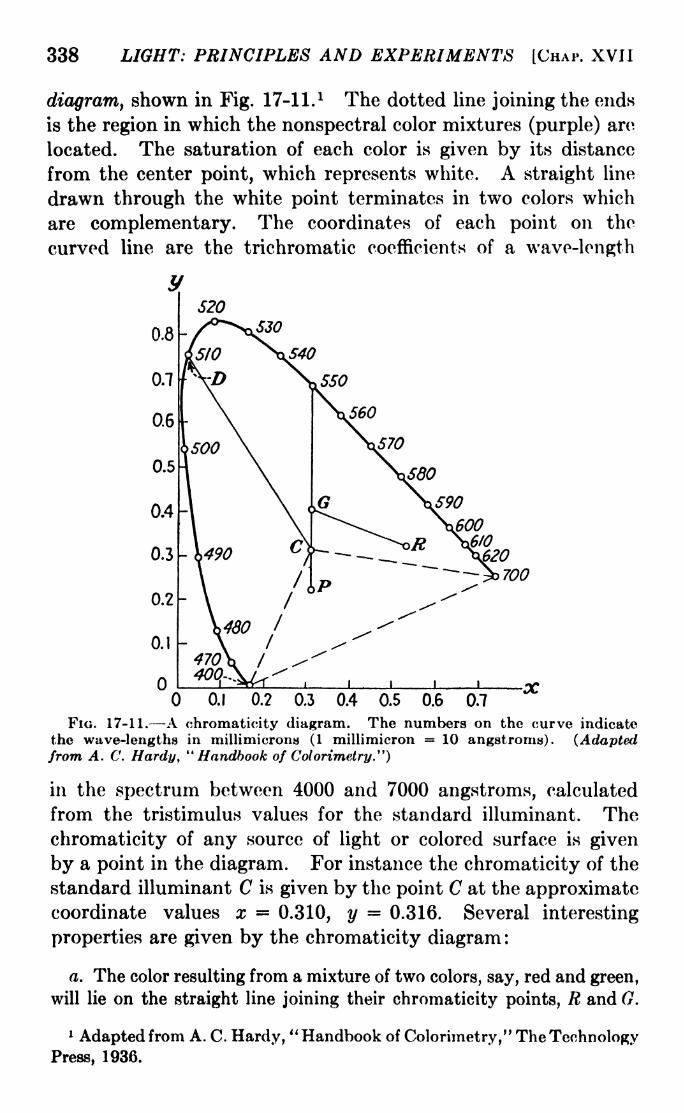
338 LIGHT: PRINCIPLES AND EXPERIMENTS [CHAP. XVII
diagram, shown in Fig. 17-11. 1 The dotted line joining the ends
is the region in which the nonspectral color mixtures (purple) are
located. The saturation of each color is given by its distance
from the center point, which represents white. A straight line
drawn through the white point terminates in two colors which
are complementary. The coordinates of each point on the
curved line are the trichromatic coefficients of a wave-length
0.1 0.2 0.3 0.4 0.5 0.6 0.7
FIG. 17-11. A chromaticity diagram. The numbers on the curve indicate
the wave-lengths in millimicrons (1 millimicron = 10 angstroms). (Adaptedfrom A. C. Hardy, "Handbook of Colorimetry")
in the spectrum between 4000 and 7000 angstroms, calculated
from the tristimulus values for the standard illuminant. The
chromaticity of any source of light or colored surface is given
by a point in the diagram. For instance the chromaticity of the
standard illuminant C is given by the point C at the approximatecoordinate values x 0.310, y 0.316. Several interesting
properties are given by the chromaticity diagram :
a. The color resulting from a mixture of two colors, say, red and green,
will lie on the straight line joining their chromaticity points, R and 0.
1 Adapted from A. C. Hardy, "Handbook of Colorimetry," The TechnologyPress, 1936.
SEC. 17-19] THE EYE AND COLOR VISION 339
b. Hence, if a straight line is drawn from C to a point I) on the curve
(see Fig. 17-11), the color corresponding to any point on that straightline will result from a mixture of illuminant C and the spectrum color
corresponding to /). The point D then gives the dominant wave-lengthof the color in question.
c. The purples are all represented by points lying within the dotted
triangle.
d. As in the case of the earlier color triangles, complementaries as,
for instance, G and P lie on a straight line drawn through C, which is
analogous to the white point.
Problems
1. An object is 30 cm. from the eye. What is the numerical aperturewhen the entrance pupil of the eye is 5 mm.?
2. A person whose vision is hypermetropic possesses a range of
accommodation permitting him to see clearly objects closer than 150 cm.
If he is fitted with glasses which are convergent lenses of 20 cm. focal
length, how near may he bring a printed page and still see the print
clearly?
3. A farsighted person can see objects clearly if they are more than
50 cm. away. If he uses a reading glass of 15 cm. focal length, whatlateral magnification does he obtain?
4. A person with normal vision adjusts a telescope for his own use.
It is then used by a person who has no power of accomodation for nearby
objects. What adjustments should the second person make? If it is
to be used instead by a person who is very shortsighted, what adjust-
ments should he make?5. Can objects bo seen distinctly when the eye and object are under
water? Explain your answer.


EXPERIMENTS IN LIGHT

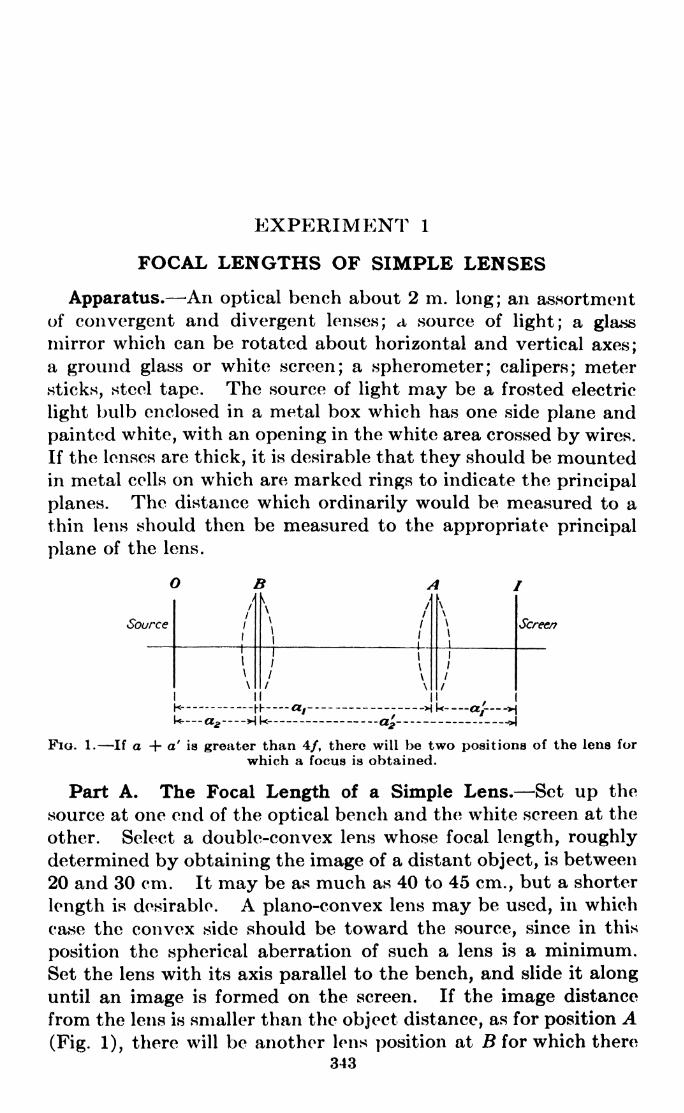
EXPERIMENT 1
FOCAL LENGTHS OF SIMPLE LENSES
Apparatus. An optical bench about 2 m. long; an assortment
of convergent arid divergent lenses; a source of light; a glassmirror which can be rotated about horizontal and vertical axes;a ground glass or white screen; a spherometer ; calipers; meter
sticks, steel tape. The source of light may be a frosted electric
light bulb enclosed in a metal box which has one side plane and
painted white, with an opening in the white area crossed by wires.
If the lenses are thick, it is desirable that they should be mountedin metal cells on which are marked rings to indicate the principal
planes. The distance which ordinarily would be measured to a
thin lens should then be measured to the appropriate principal
plane of the lens.OB A I
Fia. 1. If a + a' is greater than 4/, there will be two positions of the lens for
which a focus is obtained.
Part A. The Focal Length of a Simple Lens. Set up the
source at one end of the optical bench and the white screen at the
other. Select a double-convex lens whose focal length, roughlydetermined by obtaining the image of a distant object, is between
20 and 30 cm. It may be as much as 40 to 45 cm., but a shorter
length is desirable. A plano-convex lens may be used, in which
case the convex side should be toward the source, since in this
position the spherical aberration of such a lens is a minimum.Set the lens with its axis parallel to the bench, and slide it alonguntil an image is formed on the screen. If the image distance
from the lens is smaller than the object distance, as for position A(Fig. 1), there will be another lens position at B for which there
343

344 LIGHT: PRINCIPLES AND EXPERIMENTS
will bo an image on the screen. Then, referring to Fig. 1,
0,2= ai and 2
= a\. Measure the distances as accurately as
possible and calculate the focal length / of the lens from the
equation | 7= -v Keep in mind that unless the lens is
a a' f
thin, the values of a and a' should be measured from the object
and image planes to the principal planes P and P', respectively.
Source
Image-
Lens
r\
Pfane
Mirror
FIG. 2. Auto-collimating method for determining/.
Part B. Focal Length by the Autocollimation Method. Set
up the source, lens, and plane mirror as shown in Fig. 2, using
the same lens as in Part A. Adjust the mirror and lens so that
an image of the cross wires falls on the white surface of the lampenclosure. The distance from the lens
(or its nearer principal plane if this is
known) to the cross wires is the prin-
cipal focal length /.
Part C. Index of Refraction with a
Spherometer. First set the sphero-meter (Fig. 3) on a plane glass surface
or metal plate and screw the center
point up or down until it is just in
contact with the plate. If it is too far
down, the spherometer will rock on its
legs. Holding the center knob firmly
in this position, twist the micrometer
dial on its shaft until its zero markcomes into coincidence with the vertical
V
Fio. 3. A Bpherometer.
scale. The reading on the vertical scale is the zero markfor the measurement which is to be made, and should be
on one of the divisions. If it is not, it is probable that the
micrometer either is not flat or its plane is not perpendic-
ular to the screw of the spherometer, in which case a record

EXP. 1J FOCAL LENGTHS OF SIMPLE LENSES 345
of the variation should be made. Place the spherometer on the
lens surface to be measured and turn the center knob until the
center point just makes contact with the lens with no rocking.
Record the amount the center point has been elevated (or
depressed for a concave surface) from the zero point previouslydetermined. Press the leg points on a piece of paper and measure
the three distances d between each pair of legs, and obtain an
average value for d. In case the points are flattened by wear, be
sure that the distances measured are not to the centers of the
depressions in the paper but to the edges corresponding to the
points of the legs which were in contact with the lens surface.
Calculate the radius of curvature by means of the equation
_r ~
d 2
6id)
where s is the distance measured with the spherometer. Repeatfor the second surface. Calculate the index of refraction bymeans of the equation
1, ,Jl l\
7 = (n-
1)1 I-
/ Vi rt/(2)
Part D. The Focal Length of a Divergent Lens. Choose a
convergent lens of somewhat longer focal length than the diver-
gent lens to be measured and set it up on the optical bench as in
FIG. 4.
Fig. 4. There will be a real image at /i. Place the divergent
lens L2 between this image and LI. Then /i will serve as a
virtual source for which L2 will form an image at 72 . The
distances 7iL2 and 72L2 are a and a', respectively, in the equation
a a /
Part E. Index of Refraction of a Divergent Lens. Repeat
Part C for the divergent lens whose focal length has been found
in Part D.

346 LIGHT: PRINCIPLES AND EXPERIMENTS
PartE'. Curvature of a Concave Surface. Second Method.The curvature of the concave surface may be found by the sphe-rometer and also by another method which serves as a check on
the spherometer measurement. In a suitable clamp set up a
polished strip or small rod of metal, as for instance, a large
needle. Illuminate it with a lamp held near by, and set it at a
position in front of the concave surface where the inverted
image of its point will coincide exactly with it as shown in Fig. 5.
The point of coincidence may be determined by eliminating the
parallactic displacement as the eye is moved from side to side
and up and down. If the other lens surface also reflects enough
light to interfere, smear it with a little vaseline which can be
\Image
i
I ) i
\ i ^~-
fyeA A A / \J^*~*
~N V ,
yeti 6 fl
Eyepiece/ \
Object
FIG. 6. A point and its image coincide at the center of curvature of a sphericalmirror.
wiped off later with a soft cloth or lens paper. Some observers
will find it desirable to use an eyepiece of moderate power in
eliminating the parallax. The distance from the object point
to the lens surface is the radius of curvature of the surface.
In addition to the details of measuring technique and manipula-tive skill in this experiment, there are some important lessons
to be learned regarding the effect of inaccuracies in the different
observations. For the divergent lens, calculate the error intro-
duced into the measurement of radius of curvature by an error
of 1 per cent in the measurement of the distance between the
spherometer legs. How does this compare with the mean error
of three successive observations of r by method E"! Conclude
your report of the experiment with a discussion of the relative
accuracy of measurement of / by the methods outlined, the
probable percentage of error in the measurement of the index
of refraction, and the sources of all errors.
If the principal planes of the lenses are known, what additional
accuracy is gained by measuring all distances from them rather
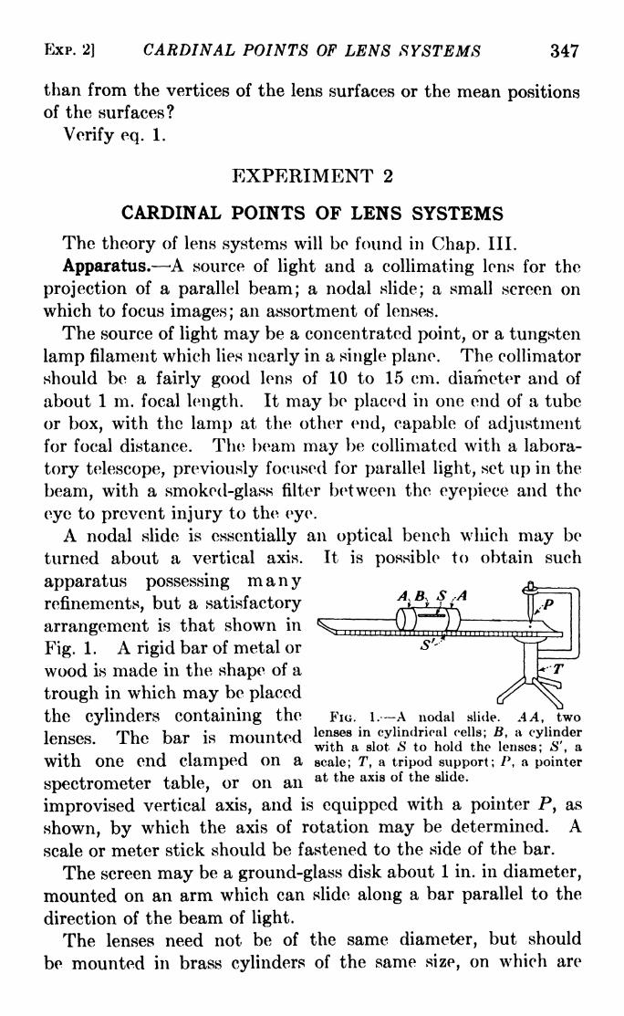
EXP. 2] CARDINAL POINTS OF LENS SYSTEMS 347
than from the vertices of the lens surfaces or the mean positionsof the surfaces?
Verify eq. 1.
EXPERIMENT 2
CARDINAL POINTS OF LENS SYSTEMS
The theory of lens systems will be found in Chap. III.
Apparatus. A source of light and a collimating lens for the
projection of a parallel beam; a nodal slide; a small screen on
which to focus images; an assortment of lenses.
The source of light may be a concentrated point, or a tungsten
lamp filament which lies nearly in a single plane. The collimator
should be a fairly good lens of 10 to 15 cm. diameter and of
about 1 m. focal length. It may be placed in one end of a tube
or box, with the lamp at the other end, capable of adjustmentfor focal distance. The beam may be collimated with a labora-
tory telescope, previously focused for parallel light, set up in the
beam, with a smoked-glass filter between the eyepiece and the
eye to prevent injury to the eye1
.
A nodal slide is essentially an optical bench which may be
turned about a vertical axis. It is possible to obtain such
apparatus possessing manyrefinements, but a satisfactory i >
; t.
arrangement is that shown in ^ , ,\)J )/"""O ^Si 1 IT 1 L I I I II 1 1 I 1 1 1 I 1 I I
jjli i i i i j
Fig. 1. A rigid bar of metal or S''''
wood is made in the shape of a
trough in which may be placed
the cylinders containing the FIG. I.--A nodal slide. A A, two
loncna TTr Kor i rnmintoH lenses in cylindrical cells; B, a cylinderlenses. ne oar in inuuiiteti .,, i * o .. u u ^.u i owith a slot o to hold the lenses; o , a
with One end clamped On a scale; T, & tripod support; /', a pointer
spectrometer table, or on an at the axis of the slide,
improvised vertical axis, and is equipped with a pointer P, as
shown, by which the axis of rotation may be determined. Ascale or meter stick should be fastened to the side of the bar.
The screen may be a ground-glass disk about 1 in. in diameter,
mounted on an arm which can slide along a bar parallel to the
direction of the beam of light.
The lenses need not be of the same diameter, but should
be mounted in brass cylinders of the same size, on which are
P
_( i i i j i i i i
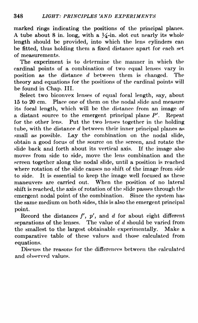
348 LIGHT: PRINCIPLES 'AND EXPERIMENTS
marked rings indicating the positions of the principal planes.
A tube about 8 in. long, with a 3^-in- slot cut nearly its whole
length should be provided, into which the lens cylinders can
be fitted, thus holding them a fixed distance apart for each set
of measurements.
The experiment is to determine the manner in which the
cardinal points of a combination of two equal lenses vary in
position as the distance d between them is changed. The
theory and equations for the positions of the cardinal points will
be found in Chap. III.
Select two biconvex lenses of equal focal length, say, about
15 to 20 cm. Place one of them on the nodal slide and measure
its focal length, which will be the distance from an image of
a distant source to the emergent principal plane P 9
. Repeatfor the other lens. Put the two lenses together in the holding
tube, with the distance d between their inner principal planes as
small as possible. Lay the combination on the nodal slide,
obtain a good focus of the source on the screen, and rotate the
slide back and forth about its vertical axis. If the image also
moves from side to side, move the lens combination and the
screen together along the nodal slide, until a position is reached
where rotation of the slide causes no shift of the image from side
to side. It is essential to keep the image well focused as these
maneuvers are carried out. When the position of no lateral
shift is reached, the axis of rotation of the slide passes through the
emergent nodal point of the combination. Since the system has
the same medium on both sides, this is also the emergent principal
point.
Record the distances /', p', and d for about eight different
separations of the lenses. The value of d should be varied from
the smallest to the largest obtainable experimentally. Make a
comparative table of these values and those calculated from
equations.Discuss the reasons for the differences between the calculated
and observed values.

Exi>. 3] A STUDY OF ABERRATIONS 349
EXPERIMENT 3
A STUDY OF ABERRATIONSFor the theory of Aberrations see Chap. VI.
Apparatus. An optical bench, a mounting for lenses with a
turntable graduated to degrees, a concentrated source of light,
lenses, diaphragms, and red, blue, and green filters.
Spherical Aberration. The source of light should preferablybe monochromatic. This may be obtained by focusing the
light of a mercury arc on a hole about 1 mm. in diameter througha color filter which transmits only the green line of mercury,5461 angstroms. If this is too faint, use a concentrated filament
lamp or a Point-o-lite. Mount the turn-
table so that it may slide along the bench.
The screen may be a large sheet of bristol
board, or white celluloid.
For a lens, an ordinary projection
lantern condenser is suitable. It should
be mounted in a brass cylinder on which
grooves are cut coinciding with the
principal planes. A diaphragm like that
shown in Fig. 1 is then mounted over the
lens. Notice that the holes are arranged,
not radially, but so that the images will not fall on each other
as the focal position is changed.The purpose of the experiment is to obtain a set of measure-
ments of the longitudinal spherical aberration (L.S.A.) for differ-
ent focal lengths. Adjust the lens in its holder with the convex
side toward the source, and with its axis passing through the
source. For several object positions, each obtained by movingthe lens, find the focal distance for rays through the center
opening, and also for rays through the openings at distances
hi t hz, and h^ from the center. The maximum range of difference
of the focal distance between the focus for the center openingand that for the outermost zone should give the L. S. A. Calcu-
late the values of the L. S. A. from the following equation:
L .S .A .. "(
~i)
.
*'[(! +1Y .
(..+_! + 1)n22L\ri a/ \ a r lj
I IV /n+l 1
n~7)
'
\~Hr- 7
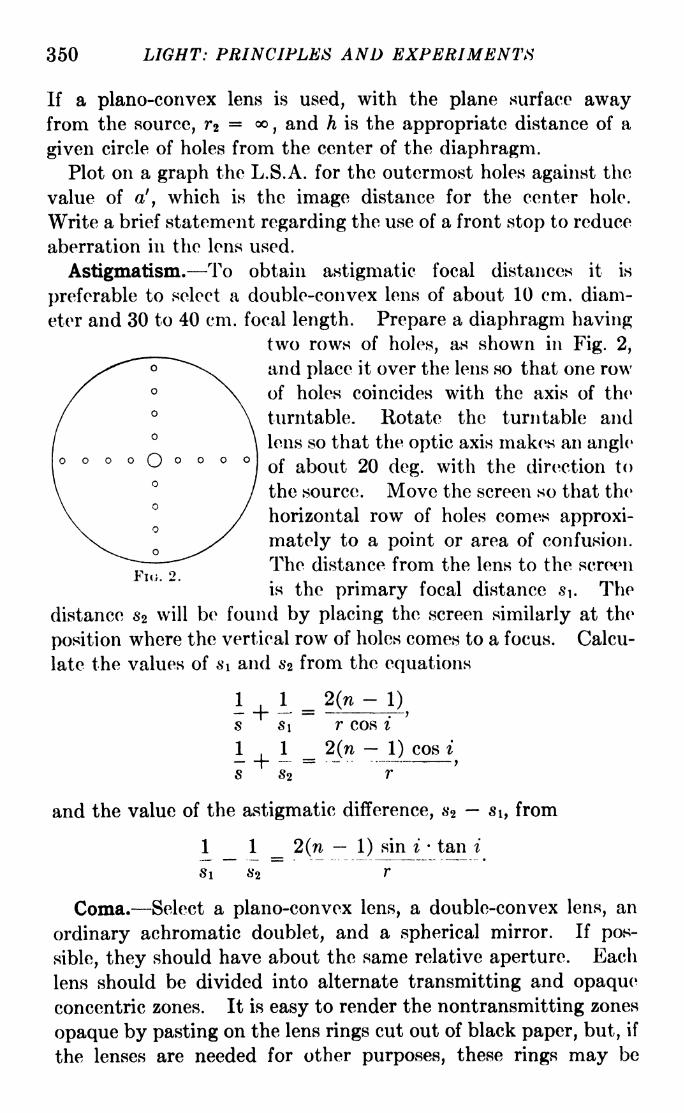
350 LIGHT: PRINCIPLES AND EXPERIMENTS
If a plano-convex lens is used, with the plane surface awayfrom the source, rz = ,
and h is the appropriate distance of a
given circle of holes from the center of the diaphragm.Plot on a graph the L.S.A. for the outermost holes against the
value of a', which is the image distance for the center hole.
Write a brief statement regarding the use of a front stop to reduce
aberration in the lens used.
Astigmatism. To obtain astigmatic focal distances it is
preferable to select a double-convex lens of about 10 cm. diam-
eter and 30 to 40 cm. focal length. Prepare a diaphragm havingtwo rows of holes, as shown in Fig. 2,
arid place it over the lens so that one row
of holes coincides with the axis of the
turntable. Rotate the turntable and
lens so that the optic axis makes an angle
of about 20 deg. with the direction to
the source. Move the screen so that the
horizontal row of holes comes approxi-
mately to a point or area of confusion.
The distance from the lens to the screen
is the primary focal distance si. The
distance s* will be found by placing the screen similarly at the
position where the vertical row of holes comes to a focus. Calcu-
late the values of s\ and s% from the equations
FIG. 2.
2(ns
-s
s\ r cos i
2(n 1) cos i. . - , .
y
r
and the value of the astigmatic difference, s2 i, from
1 1 2(n 1) sin i- tan i
Coma. Select a plano-convex lens, a double-convex lens, an
ordinary achromatic doublet, and a spherical mirror. If pos-
sible, they should have about the same relative aperture. Each
lens should be divided into alternate transmitting and opaqueconcentric zones. It is easy to render the nontransmitting zones
opaque by pasting on the lens rings cut out of black paper, but, if
the lenses are needed for other purposes, these rings may be

EXP. 3] A STUDY OF ABERRATIONS 351
pasted on a thin disk of glass the size of the lens. A transmittingcenter disk and three transmitting zones are recommended.The source should be a small point of high intensity. This can
be a Poirit-o-lite lamp or an illuminated pinhole about 1 mm. in
diameter. If sunlight is available, the experiment may be
performed in parallel light. Obtain an axial image with each
lens, tilt the lens, and refocus. In general it will be difficult to
observe the comatic images without tilting the lens to so large an
angle that astigmatism will also be present.Make as accurately as possible a drawing of the comatic
images with each lens. For which, if any, of the lenses or mir-
rors used, is coma absent?
Curvature of the Field and Distortion. For simple lenses these
aberrations are marked with objects having large area. It is
difficult, however, to distinguish between curvature of the field
and astigmatism. The distortion due to a doublet of two convexlenses will be examined. Select two equal double-convex lenses
of about 6 cm. aperture and 15 cm. focal length, each mountedin a tube so that the two may be placed different distances
apart by sliding the lens tubes into another one which fits them
tightly. For the source use a blackened photographic plate
ruled with a rectangular grid of scratches about 1 cm. apart.
This is to be backed with a sheet of thin white paper and illumi-
nated from behind with a strong source of light.
Measure the change in focus for regions of the image field at
different distances from the axis. This will give the curvature
of the field. Measure also the difference in magnification for
different zones. This will give the distortion. Plot both the
curvature and the distortion separately as ordinates on a single
sheet of graph paper, against the distance from the axis as
abscissa.
Chromatic Aberration. Mount the plano-convex lens used
in the determination of spherical aberration with a concentrated
filament for a source. With a red filter, measure the focal dis-
tance. Repeat with a blue filter. The difference in focus is a
measure of the chromatic aberration. Repeat the experimentwith an ordinary achromatic doublet.

352 LIGHT: PRINCIPLES AND EXPERIMENTS
EXPERIMENT 4
MEASUREMENT OF INDEX OF REFRACTION BY MEANSOF A MICROSCOPE
Apparatus. This consists mainly of a microscope mounted
horizontally on a carriage in fairly accurate ways so that it is
capable of horizontal motion of a few centimeters. The dis-
tance moved is measured by means of a linear scale and a microm-
eter head graduated to thousandths of a millimeter. In case the
movable carriage and micrometer are not available, a tenth-
millimeter scale may be attached to the horizontal microscopeand the distance it is moved may be measured by means of a
second, vertical, microscope focused on the scale and equippedwith a micrometer eyepiece. In some cases high-grade micro-
scopes are equipped with micrometers capable of measuring the
focusing distance with great accuracy, so that no auxiliary
measuring microscope is needed.
There should also be an adjustable stand on which specimensand cells may be mounted in front of the horizontal microscope,
and a source of light, preferably diffuse.
Part A. Refractive Index of a Glass Block. The block to be
examined should be one for which the index can also be measured
by means of the grazing incidence method (see
Experiment 7) and should therefore be a rec-
tangular block with one end and two sides
polished. The distance between the sides Aand B (Fig. 1) is measured with a micrometer
caliper to hundredths of a millimeter. Sprinkle
a few grains of lycopodium powder on the
surfaces. The microscope is first focused on a
grain at A, and its position read, then on a grain at J3, and a reading
taken. Since the angles of incidence of the rays entering the
microscope are very small, to a high degree of approximation the
distance the microscope is moved between readings is equal to
the actual distance AB divided by the index of refraction of the
glass. From this the index may be calculated.
Part B. Refractive Index of a Liquid. Use one of the liquids
to be examined in Experiment 7. First, on the inside walls of a
dry cell with parallel glass walls like that shown in Fig. 2, sprinkle
a little lycopodium powder and measure the distance between

EXP. 5] THE PRISM SPECTROMETER 353
the walls by the method described in Part A. In this case,
however, the distance moved by the microscope between readingswill be the actual separation of the inner
walls of the cell. Then remove the
powder from the inner walls and sprinkle
a little on the outer walls, and repeat the
measurements. Then, without movingthe cell, place the liquid in it, and re-
measure the distance (apparent) between
the outer walls. If a is the apparentdistance measured between the outer
walls without the liquid, b the apparent distance between themwith the liquid, and r the actual distance between the inner
walls, then
Fio. 1.
r - (a-
6)
Answer the following questions :
1. How many figures after the decimal place in the value of n are you
justified in retaining? Explain your answer.
2. What error in Part A would be introduced by having an angle of
5 deg. between the normal to the plane surfaces and the axis of the
microscope?3. What error in Part H would be introduced under the same
conditions?
4. Justify the assumption involved in the statement that the angle
can be substituted for its sine in making the measurements in this
experiment.
EXPERIMENT 5
THE PRISM SPECTROMETER
Apparatus. A spectrometer equipped with a Gauss eye-
piece, a prism of approximately 60 deg. refracting angle, an
extra slit to be fitted over the telescope objective, a white light
source, a mercury arc, a helium source.
The adjustment of the spectrometer should be made first
according to the directions in Appendix IV. It is recommended
that the student read through these directions with a view to
understanding their purpose, rather than follow them line byline without appreciating the significance of each operation.
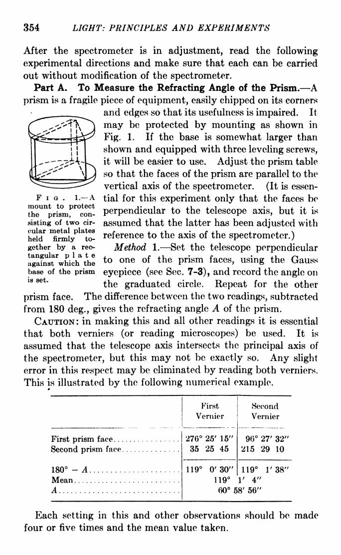
354 LIGHT: PRINCIPLES AND EXPERIMENTS
After the spectrometer is in adjustment, read the following
experimental directions and make sure that each can be carried
out without modification of the spectrometer.
Part A. To Measure the Refracting Angle of the Prism. Aprism is a fragile piece of equipment, easily chipped on its corners
and edges so that its usefulness is impaired. It
may be protected by mounting as shown in
Fig. 1. If the base is somewhat larger than
shown and equipped with three leveling screws,
it will be easier to use. Adjust the prism table
so that the faces of the prism are parallel to the
vertical axis of the spectrometer. (It is essen-
tial for this experiment only that the faces be
perpendicular to the telescope axis, but it is
assumed that the latter has been adjusted with
reference to the axis of the spectrometer.)Method 1. Set the telescope perpendicular
to one of the prism faces, using the Gauss
eyepiece (see Sec. 7-3), and record the angle on
the graduated circle. Repeat for the other
prism face. The difference between the two readings, subtracted
from 180 deg., gives the refracting angle A of the prism.
CAUTION: in making this and all other readings it is essential
that both verniers (or reading microscopes) be used. It is
assumed that the telescope axis intersects the principal axis of
the spectrometer, but this may not be exactly so. Any slight
error in this respect may be eliminated by reading both verniers.
This is illustrated by the following numerical example.
FIG. 1. Amount to protectthe prism, con-
sisting of two cir-
cular
held
gether by a rec-
tangular plateagainst which the
base of the prismis set.
Each setting in this and other observations should be madefour or five times and the mean value taken.

EXP. 5] THE PRISM SPECTROMETER 355
Fu;. 2.
Method 2. Project the light through the slit and collimator
lens (white light will do) and set the prism on the table with the
refracting edge at the center as in Fig. 2. Set the telescope in
position I so that the reflected image of the slit in good focus is
exactly at the intersection of the
cross hairs. Repeat for position II.
The angle between the two settings
of the telescope is twice the prism
angle.
Part B. To Find the Index of
Refraction and Dispersion Curve of
the Prism by the Use of the Angleof Minimum Deviation. For this
part of the experiment a discharge
tube containing helium and mercuryin correct quantities to yield spectra
of approximately equal strengths
is excellent, although two separate
sources may be used. If the helium source is not available, someother such as hydrogen or neon may be used, or even sunlight.
All that is required is a dozen or so easily distinguishable lines
throughout the range of the visible spectrum. Do not use a slit
that is too wide. The spectrum lines should be so narrow that
they appear as sharp lines with no perceptible evidence of the
width of the slit. A table of wave-lengths of suitable elements
is given in Appendix VI.
With the prism removed, and a mercury source in front of the
slit, set the telescope and collimator in line so that the imageof the slit falls exactly on the cross hairs, and record the'angle
of the telescope. Then place the prism on the table as in Fig. 3.
Do not move the collimator, but set the prism so that the light
from the slit completely fills one face of the prism. Swing the
telescope to one side and look directly at the spectrum in the
other face of the prism. Rotate the prism table and prism
about the vertical axis, first in one direction, then in the other,
watching the spectrum at the same time. It will be noted that
as the prism is rotated, the spectrum changes position, but for
a particular angle of the prism the direction of motion of the
spectrum reverses. That is, if the prism and collimator occupythe position shown in Fig. 3, as the prism is turned clockwise,
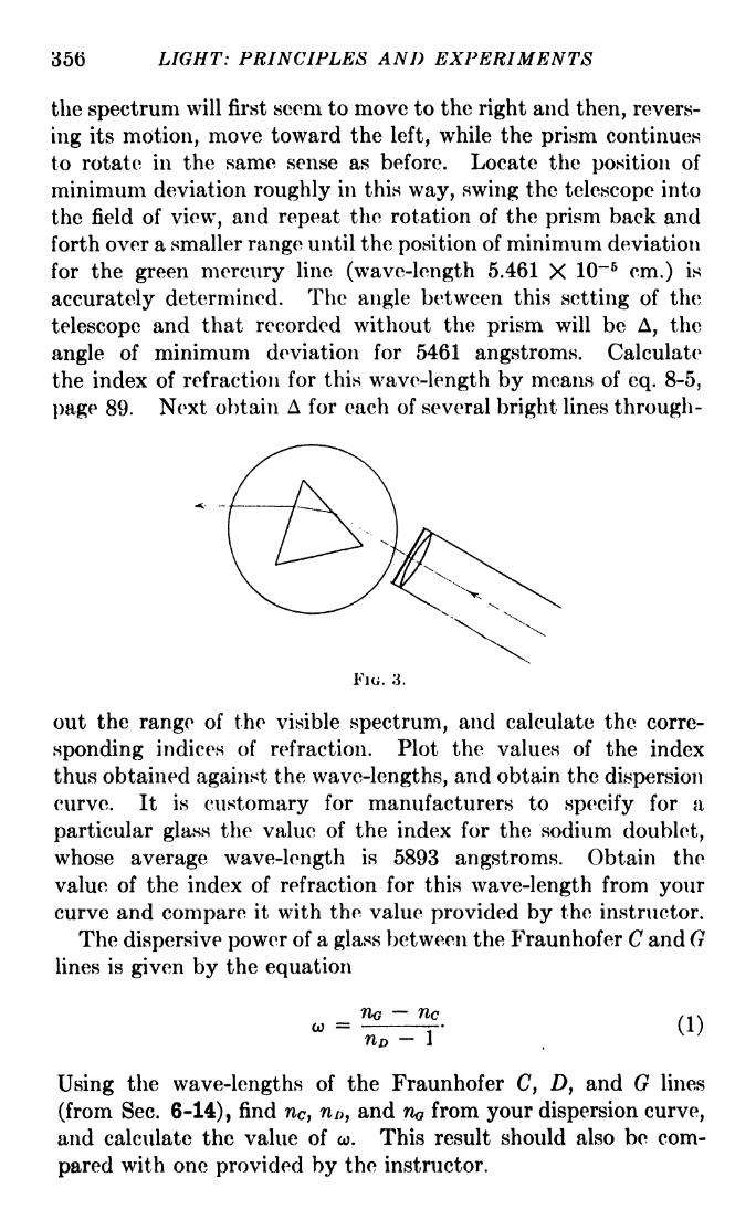
35(5 LIGHT: PRINCIPLES AND EXPERIMENTS
the spectrum will first seem to move to the right and then, revers-
ing its motion, move toward the left, while the prism continues
to rotate in the same sense as before. Locate the position of
minimum deviation roughly in this way, swing the telescope into
the field of view, and repeat the rotation of the prism back and
forth over a smaller range until the position of minimum deviation
for the green mercury line (wave-length 5.461 X 10~ 6cm.) is
accurately determined. The angle between this setting of the
telescope and that recorded without the prism will be A, the
angle of minimum deviation for 5461 angstroms. Calculate
the index of refraction for this wave-length by means of eq. 8-5,
page 89. Next obtain A for each of several bright lines through-
Fio. 3.
out the range of the visible spectrum, and calculate the corre-
sponding indices of refraction. Plot the values of the index
thus obtained against the wave-lengths, and obtain the dispersion
curve. It is customary for manufacturers to specify for a
particular glass the value of the index for the sodium doublet,
whose average wave-length is 5893 angstroms. Obtain the
value of the index of refraction for this wave-length from yourcurve and compare it with the value provided by the instructor.
The dispersive power of a glass between the Fraunhofer C and Glines is given by the equation
no /,>.W =-r- (1)
Using the wave-lengths of the Fraunhofer C, D, and G lines
(from Sec. 6-14), find nc , n/>, and no from your dispersion curve,
and calculate the value of w. This result should also be com-
pared with one provided by the instructor.
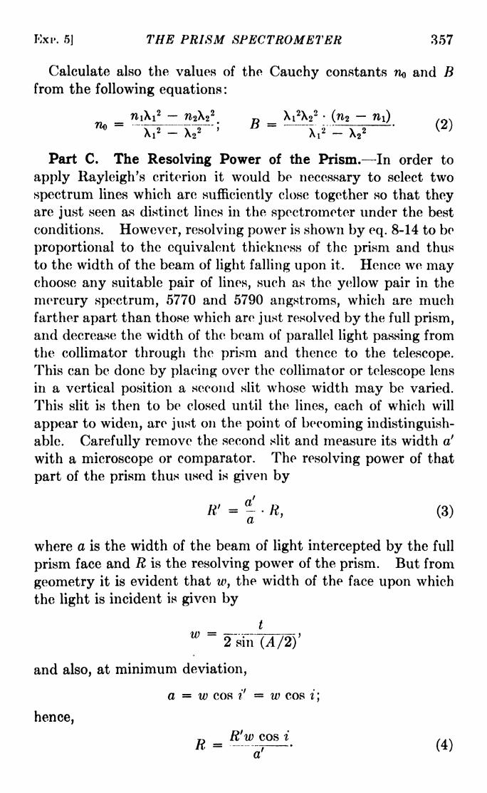
Kxi>. 5] THE PRISM SPECTROMETER 357
Calculate also the values of the Cauchy constants no and Bfrom the following equations :
Xi2X2
2(n2
-
Part C. The Resolving Power of the Prism. In order to
apply Rayleigh's criterion it would be necessary to select two
spectrum lines which are sufficiently close together so that theyare just seen as distinct lines in the spectrometer under the best
conditions. However, resolving power is shown by eq. 8-14 to be
proportional to the equivalent thickness of the prism and thus
to the width of the beam of light falling upon it. Hence we maychoose any suitable pair of lines, such as the yellow pair in the
mercury spectrum, 5770 and 5790 angstroms, which are muchfarther apart than those which are just resolved by the full prism,
and decrease the width of the beam of parallel light passing from
the collimator through the prism and thence to the telescope.
This can be done by placing over the collimator or telescope lens
in a vertical position a second slit whose width may be varied.
This slit is then to be closed until the lines, each of which will
appear to widen, are just on the point of becoming indistinguish-
able. Carefully remove the second slit and measure its width a'
with a microscope or comparator. The resolving power of that
part of the prism thus used is given by
R' = R, (3)
where a is the width of the beam of light intercepted by the full
prism face and R is the resolving power of the prism. But from
geometry it is evident that w, the width of the face upon which
the light is incident is given by
t
w = =--.-2 sin (A/2)
and also, at minimum deviation,
a = w cos i' = w cos i;
hence,
R'w cos i ,.,

358 LIGHT: PRINCIPLES AND EXPERIMENTS
Now we can calculate R' for the width a', from the fundamentaldefinition of resolving power, i.e.,
Thus, by eq. 3, R can be obtained from the experimental results.
For the average wave-length used, calculate also the value of Rfor the entire prism from
2BtK =
X3
and compare it with the experimental result. Compute from
R = aD where D is the dispersion of the prism, the values of the
resolving power for several wave-lengths.
EXPERIMENT 6
THE SPECTROPHOTOMETERSpectrophotometers which make possible the comparison of
the intensities of sources over small ranges of wave-length may be
constructed in various ways. Two forms will be described here,
in both of which the actual comparisonis effected by the use of polarized light.
The Glan Spectrophotometer. This
instrument is similar to the ordinary
spectrometer, but has certain modifi-
cations making possible the comparisonof two sources. The light from one of
these passes directly into the upper
portion Si of the slit (Fig. 1), while
that from the other is directed into the lower portion $2 bymeans of a total reflecting prism. Inside the collimator tube,
at a suitable distance from the slit, is placed a Wollaston prism
(see Sec. 13-10). This prism divides the light from each of the
sources into two beams which arc polarized so that the directions
of their plane vibrations are perpendicular to each other. These
four beams are refracted by an ordinary 60-deg. prism set on the
spectrometer table, so that four parallel spectra are formed, one
above the other. The middle two of these which we may call
spectrum 2 and spectrum 3 are from /Si and Sz or vice versa, and
consist of light vibrations which are in perpendicular planes.
Spectra 1 and 4 do not appear in the field of view of the eyepiece.
Between the collimator lens and the refracting prism is placed a
FIG. 1.
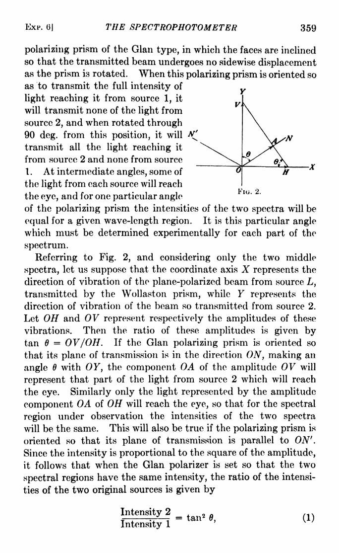
EXP. 6j THE SPECTROPHOTOMETER 359
polarizing prism of the Glan type, in which the faces are inclined
so that the transmitted beam undergoes no sidewise displacementas the prism is rotated. When this polarizing prism is oriented so
as to transmit the full intensity of
light reaching it from source 1, it
will transmit none of the light from
source 2, and when rotated through90 deg. from this position, it will A!
transmit all the light reaching it
from source 2 and none from source~i~ T M> .._.
1. At intermediate angles, some of Jf
the light from each source will reachKic 2
the eye, and for one particular angle
of the polarizing prism the intensities of the two spectra will be
equal for a given wave-length region. It is this particular anglewhich must be determined experimentally for each part of the
spectrum.
Referring to Fig. 2, and considering only the two middle
spectra, let us suppose that the coordinate axis X represents the
direction of vibration of the plane-polarized beam from source L,
transmitted by the Wollaston prism, while Y represents the
direction of vibration of the beam so transmitted from source 2.
Let OH and 0V represent respectively the amplitudes of these
vibrations. Then the ratio of these amplitudes is given bytan 6 = 0V/OH. If the Glan polarizing prism is oriented so
that its plane of transmission is in the direction ON, making an
angle 6 with OF, the component OA of the amplitude 0V will
represent that part of the light from source 2 which will reach
the eye. Similarly only the light represented by the amplitude
component OA of OH will reach the eye, so that for the spectral
region under observation the intensities of the two spectra
will be the same. This will also be true if the polarizing prism is
oriented so that its plane of transmission is parallel to ON'.
Since the intensity is proportional to the square of the amplitude,
it follows that when the Glan polarizer is set so that the two
spectral regions have the same intensity, the ratio of the intensi-
ties of the two original sources is given by
Intensity 2 ,.
,,,.
.jr,-^r = tan2
0, (1)Intensity 1

360 LIGHT: PRINCIPLES AND EXPERIMENTS
where is the angle between the setting of the polarizing prismfor equal intensities and the setting for complete extinction of
the light from source 1.
An ordinary spectrometer may be converted into a Glan
spectrophotometer with a few changes. Across the middle of
the slit is placed a strip which blocks the light and effectively
divides the slit into an upper and a lower portion. The Wollaston
prism is inserted in the tube so that the images from Si and $2
(Fig. 1), coincide vertically. It should be possible to rotate the
Wollaston through a small angle about the optical axis, and to
move it along the collimator tube a short distance in either direc-
tion. A nicol in a holder having a circle preferably graduatedin four quadrants is fitted on the end of the collimator tube
between the lens and the refracting prism. The eyepiece is
equipped with a pair of long slit jaws which may be opened wide
enough so as to permit a view of the entire spectrum, or closed
so as to permit the transmission of a band of only about 25 to 30
angstroms. This slit, or diaphragm, should be mounted at the
focal plane of the eyepiece.
Part A. The Comparison of Continuous Spectra. The dis-
tribution of intensities of a number of sources may be comparedwith that of a standard lamp. While an accurate standard maybe used, it is neither necessary nor advisable for ordinary class
studies. It is satisfactory to use instead an ordinary new 40-watt
Mazda lamp as an arbitrary standard. To this a sticker should
be affixed near the base to indicate the side of the lamp from
which the light is to be taken throughout a series of measure-
ments, since the brightness of such a lamp is not the same whenviewed from different directions. With this improvised standard
several sources may be compared, as, for instance, an old-
fashioned carbon filament lamp, a ruby lamp, a gasoline Welsbach
lamp, or sunlight. The intensity distribution in the light from a
second 40-watt, 110-volt lamp operated on 135 to 150 volts mayalso be studied, if voltages higher than 110 are available, or a
lamp of lower rated voltage than 110 may similarly be overrun.
To place the two spectra exactly one above the other, a mer-
cury arc or other bright-line source may be used in front of the
slit with the total reflection prism removed. If the bright lines
due to light passing through Si and S2 are not exactly in line,
the Wollaston prism should be rotated slightly until the spectra

EXP. 6] THE SPECTROPHOTOMETEli 361
coincide vertically. At the same time, if the two .spectra are not
exactly edge to edge, a slight displacement of the Wollaston
prism may be made along the tube to bring them together with-
out overlapping or separation.The prism which refracts the light is next to be calibrated.
Setting it for minimum deviation approximately for the yellow,
using any convenient lines, such as the sodium lines or the
mercury lines, the angle of the telescope should be plotted against
wave-length for a number of positions in the spectrum. Either
sunlight or ordinary laboratory sources will serve for this purpose.It is not necessary to read the angle of the telescope closer than
Y deg. for any setting, since the comparisons to be made later
are of regions of the spectrum several angstroms in width.
Enough readings should be taken, however, so that a graph
may be made, with wave-lengths as abscissas and telescope
settings as ordinates. After the points are plotted, a smooth
curve should be drawn through them, so that for any subsequent
position of the telescope the corresponding wave-length may be
quickly read from the graph.
Next set up the standard lamp and the source to be comparedwith it. If clear glass lamps are used, a piece of finely ground
glass should be placed between each lamp and the slit, and as
close to the former as possible without the risk of breakage byheat. Glass ground to a sufficiently fine grain may be made by
grinding lantern-slide cover glasses with fine carborundum, or
emery, and water, using a flat piece of iron as a tool. When the
lamps are accurately in place and the zero position of the polarizing
prism determined, set the telescope on a region in the red end of
the spectrum, rotate the polarizing prism until the spectra
of the two sources appear the same intensity, and record the
setting of the polarizer. Make several settings for each position
in the spectrum, and average their values. Then move the
telescope to successive regions of the spectrum about 100 or
200 angstroms apart, and make similar observations. Calculate
the intensity ratios by means of eq. 1, and plot the values
obtained. (Remember that the telescope gives an inverted
image of the slit.
Part B. Absorption of Colored Transmitting Substances.
Using the same adjustments as in Part A, allow the light from the
standard source to pass through both parts of the slit, and place

362 LIGHT: PRINCIPLES AND EXPERIMENTS
a piece of didymium glass about 5 mm. thick over the lower part.
Measure and plot the relative transmissions for each spectral
region as outlined above. Other substances whose absorption
may be measured are solutions of potassium permanganate,cobalt chloride, and thin films of metal evaporated or otherwise
deposited on glass. A very useful chart of the transmissions of
about 50 substances is to be found on page 16 of Wood's "Phys-ical Optics," 1911 edition. Extensive tables of the spectral
transmissions of substances are also to be found in the "Hand-book of Chemistry and Physics," published by the Chemical
Rubber Company, and others are procurable from the CorningGlass Works, the Eastman Kodak Company, and Jena Glass
Works (Fish-Schurman Company, agents).
Part C. (Optional) Relative Intensities of Bright Lines in a
Spectrum. By using a slit of sufficient width so that each brightline from a source such as the mercury arc appears as a narrow
rectangle of light, the intensities of lines in discontinuous spectra
may be compared with the spectrum of a white-light source.
This comparison, however, cannot be used to obtain the relative
intensities within the discontinuous spectrum itself unless the
distribution of intensity in the white-light source is known.
While this distribution can be measured for any continuous
spectrum, it is perhaps best to use a standardized and calibrated
white-light source for this part of the experiment.
A tungsten ribbon lamp operated at a sufficiently high tempera-ture may be said to radiate in accordance with the Wien distri-
bution law, which may be written
E\ -VC2/XT\5 >
where E\ is the energy radiated for a particular wave-length X,
T is the absolute temperature, and Ci and c% are constants. The
value of c2 is commonly taken as 1.433 cm.-deg. On p. 363 is a
calibration for brightness temperature of a special standard
lamp, made of a tungsten ribbon filament.
This lamp, operated on a current of 26 to 28 amp., may be
said to approximate a black body. Hence, by Wien's law, the
energy distribution in its spectrum may be calculated. If this
distribution is known, it is possible to obtain with a fair degree
of accuracy the distribution of intensity in the visual part of a

EXP. 6] THE SPECTROPHOTOMETER 363
spectrum which is compared with it. However, the student is
to be warned against undertaking this part of the experiment
RELATION BETWEEN CURRENT AND TEMPERATURECurrent, amp. Brightness temperature, K.
13.0 1,48415.5 1,66718.5 1,85622.5 2,07627.0 2,30032.5 2,549
without careful supervision by the instructor, since calibrated
lamps are expensive and may easily be ruined.
In reporting this experiment, answer the following question:
In adjusting the Wollaston prism so that the two spectra aro
exactly edge to edge, it will probably be found that when theyare so adjusted in the red, they will overlap in the blue or vice
versa. Explain why this should be so.
FIG. 3. The Brace-Lemon spectrophotometer. C\ and Cz, collimators; N\ andN, nicols; T, telescope; B, Brace prism.
The Brace-Lemon Spectrophotometer. Another type of spec-
trophotometer which may be used with considerable precision is
the Brace-Lemon, illustrated in Fig. 3. It has two identical
collimators, in one of which are set two Glan polarizing prisms.
The prism nearer the collimator lens is fixed in azimuth, while
the other may be rotated. The dispersive instrument is a Brace
compound prism made of two 30-deg. prisms. On one of these
is deposited an opaque coat of suitable metal of high reflecting

364 LIGHT: PRINCIPLES AND EXPERIMENTS
power, which covers the middle section of the prism face, the
dividing edges between this coat and the unobstructed portionsof the face being perpendicular to the refracting edge of the
prism. Sometimes the reflecting coat is deposited on one half
of the prism face, the upper or lower, and the remaining half
left transparent. The two 30-deg. prisms are then sealed
together with Canada balsam, so that the reflecting coat is
between the two halves of the compound prism.
This instrument has the advantage that when the compoundprism is properly made and adjusted with reference to the
optical path of the light, the dividing line between the two
spectra to be compared is rendered invisible.
In order to make a comparison of two sources, one of them is
set before each slit, and the rotatable prism, whose zero position
has been previously determined, is turned until the intensities
in a given spectral region are the same.
Since the Brace compound prism is fragile and the adjustmentsmust be made very exactly, it is perhaps desirable that the
instrument be of a fixed form, and not adjustable by the student.
In case adjustments are necessary, they may be made as follows:
1. The spectrometer should be adjusted with the Brace prism removed
in the same manner as for any similar instrument, the essential require-
ments being that the axis of each collimator and that of the telescope
should be perpendicular to the vertical axis of the instrument, and that
the axis of rotation of the telescope should coincide with that vertical
axis.
2. The rotatable polarizing prism A'i should be set for minimum
transmission; i.e., its plane of transmission should be set parallel to
that of iV 2 .
3. The Brace prism should be replaced, leveled so that its faces are
parallel to the vertical axis, and set at the proper height. It should
then be set for minimum deviation for the yellow.
4. The prism should be calibrated in the manner outlined for the
Glan spectrophotometer, and a calibration curve constructed by means
of which the approximate wave-length region be found for any angle of
the telescope.
6. The collimator slits should be the same width. For this purpose,
it is essential that each should be provided with a micrometer head.
It will be necessary to determine the zero, i.e., the setting for which no
light passes through the slit, for each micrometer, since the slit rnay not
be closed when the head reads zero.
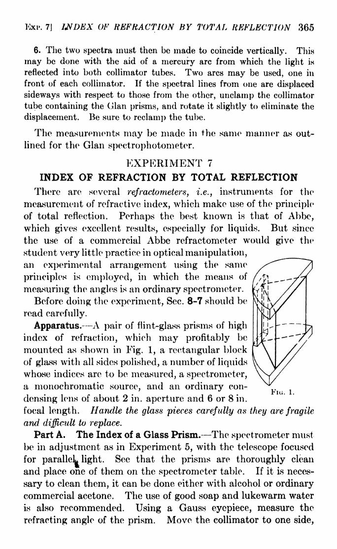
Kxr. 7] WDEX OF REFRACTION BY TOTAL REFLECTION 365
6. The two spectra must then be made to coincide vertically. This
may be done with the aid of a mercury arc from which the light is
reflected into both collimator tubes. Two arcs may be used, one in
front of each collimator. If the spectral lines from one are displaced
sideways with respect to those from the other, unclamp the collimator
tube containing the Glan prisms, arid rotate it slightly to eliminate the
displacement. Be sure to reelamp the tube.
The measurements may be made in the same manner as out-
lined for the Gian speetrophotometer.
EXPERIMENT 7
INDEX OF REFRACTION BY TOTAL REFLECTIONThere are several refractometers, i.e., instruments for the
measurement of refractive index, which make use of the principle
of total reflection. Perhaps the best known is that of Abbe,which gives excellent results, especially for liquids. But since
the use of a commercial Abbe refractometer wovdd give the
student very little practice in optical manipulation,an experimental arrangement using the same
principles is employed, in which the means of
measuring the angles is an ordinary spectrometer.
Before doing the experiment, Sec. 8-7 should be
read carefully.
Apparatus. A pair of flint-glass prisms of high
index of refraction, which may profitably be
mounted as shown in Fig. 1, a rectangular block
of glass with all sides polished, a number of liquids
whose indices are to be measured, a spectrometer,
a monochromatic source, and an ordinary con-
densing lens of about 2 in. aperture and 6 or 8 in.
focal length. Handle the glass pieces carefully as they are fragile
and difficult to replace.
Part A. The Index of a Glass Prism. The spectrometer must
be in adjustment as in Experiment 5, with the telescope focused
for paralleL light. See that the prisms are thoroughly clean
and place one of them on the spectrometer table. If it is neces-
sary to clean them, it can be done either with alcohol or ordinary
commercial acetone. The use of good soap and lukewarm water
is also recommended. Using a Gauss eyepiece, measure the
refracting angle of the prism. Move the collimator to one side,
FIG. 1.

366 LIGHT: PRINCIPLES AND EXPERIMENTS
or, if it is rigidly mounted, rotate the prism table. Adjust the
source and condensing lens so that a broad beam illuminates the
entire diagonal face of the prism. Looking into the face AB(Fig. 2) at the illumination, with the telescope swung to one
side, rotate the prism table until the field of view observed at e
is divided by a sharp vertical line on one side of which the field
is not illuminated. It is essential that no light from the source
fall on the side BC, which can be covered with a screen of card-
board. The bright side of the field will obviously coincide with
light which is incident upon the diagonal face at angles less than
90 deg., and in the case illustrated in Fig. 2 it will be on the left
of the field of view. As the table and prism are rotated, the
bright field will become narrower and will be seen to have a
sharp vertical edge. A precaution to be taken at this point is
to be sure that this apparent division between light and dark is
not an image of the boundary of the source itself. This can be
done by shifting the source or condenser lens slightly from side to
side, observing carefully meanwhile to see whether the apparentdivision also moves. The telescope is now to be swung into the
field of view, and the cross hairs set accurately on the line of
division. Record the setting of the telescope on the divided
circle. Then by means of the Gauss eyepiece set the telescope
perpendicular to the face AB of the prism and record the angle.
The difference between these two settings will be the angle i'
of eq. 8-19. The index of refraction may now be found bymeans of eq. 8-20 since the medium m in this case is air, the
index of which is practically unity. Putting nm 1, and
solving for ng ,we have.
- (sin i' + cos 4V2
fig tyA "l 1.
sin 2 A
Since the angle i' may be either on the left- or right-hand side
of the normal to the surface AB, it may be either positive or
negative; in the illustration in Fig. 2 it is positive.

KXP. 7] INDEX OF REFRACTION BY TOTAL REFLECTION 367
Part B. Index of Refraction of a Liquid. Liquids which maybe conveniently tested are: Distilled water, glycerin, and cedar
oil which has been prepared for oil immersion in microscopes.Put a drop of the liquid whose index is to be measured on tho
diagonal face of one of the prisms, and lay the other gently on it,
so that the two form a rectangular block. Do not press them
B
FIG. 3.
together tightly. Set them on the prism table and illuminate as
shown in Fig. 3. Rotate the table until the division of the field
into light and dark areas is in the field of view, as in Part A.
The selection of the dividing boundary will be aided in this
case by the fact that interference fringes are formed in the thin
film of liquid between the prisms. These fringes will in general
appear tangent to the boundary, as in Fig. 4. If the prisms are
pressed together too tightly, the fringes will be so sharp and
FIG. 4. The boundaryis the vertical division in
the middle.
FIG. 5.
conspicuous as to make the setting of the cross hairs on the
boundary difficult. As in Part A, record the setting of the
telescope for the boundary and the normal to the surface.
Remember that i' may be either negative or positive. By meansof eq. 8-19 the index of refraction of the liquid may be calculated.
Part C. Index of Refraction of a Glass Plate. Thoroughlyclean the 45 deg. prisms. Put on the surface of one of them a dropor two of some liquid whose index is higher than that of the
glass plate, and place the block gently on the face AC, as shown
in Fig. 5. Liquids suitable for the purpose are: Methylene

368 LIGHT: PRINCIPLES AND EXPERIMENTS
iodide, index 1.74; a-monobromnapthalene, index 1.66; aniline,
index 1.56. Locate the boundary between the light and dark
fields as before. It will be distinguished as in Part B by the
presence of interference fringes. There may be two boundaries,
one corresponding to the index of the glass block, the other
to the index of the liquid. The one to be chosen is that corre-
sponding to the smaller index. Carry out the measurements
as in Part B, and calculate the index of refraction for the glass
block by means of eq. 8-20.
EXPERIMENT 8
WAVE-LENGTH DETERMINATION BY MEANS OFFRESNEL'S BIPRISM
The theory of the Fresnel apparatus is to be found in Sees. 10-6
and 10-7.
Apparatus. An optical bench about 2 m. long, a mercury
arc, a filter transmitting only 5461 angstroms, an accurate slit, a
biprism mounted in a rotatable holder provided with a circular
rack so that the biprism may be rotated about an axis perpen-
Filkr. >-S/it Cross-
FIG. 1.---Arrangement of apparatus for use of Fresnel oiprism.
dicular to the common prism base, a high power micrometer
eyepiece with cross hairs, an achromatic lens of about 30 cm.
focal length and 5 cm. aperture. On account of the dimness
of the fringes, it is advisable to perform this experiment in a
separate room, or in a space sufficiently screened so that there
is no disturbance from other light sources.
Part A. The apparatus is shown in Fig. 1. Be careful to place
the biprism not more than about 35 cm. from the slit. Makesure that the cone of light from the slit covers the biprism, and
have the slit quite narrow. Adjust all parts so that the optical
axis is horizontal arid centered with respect to each part. Set
the common face F of the biprism toward the slit and perpen-dicular to the direction of light. This may be done with sufficient
accuracy by sighting down the biprism and, if need be, getting
the image of the slit which is reflected from F into coincidence
with the slit opening. Move the eyepiece along the bench out

EXP. 8] FRESNEL'S B1PRJSM 369
of the way and place the eye at E in the figure. A very fine
pattern of fringes will be seen between the two virtual images of
the slit. Next place the eyepiece, previously accurately focused
on the cross hairs, at E and look through it. Be sure of at least
four settings. Let Si, s2 ,s3 ,
s4 ,and s5 be those fringe positions
on the left-, and si', s2', s3', /, and s6' be those on the right-hand
side of the pattern. Suppose also that Si is the 30th fringe
from 81. Then the value of e obtained from
Si-
Si
is 30 times as accurate as that obtained by measuring the distance
between any two consecutive fringes, since any lack of precision
in making the settings is divided by 30. Thus five independentdeterminations of e may be made, each of a high degree of
accuracy, from which a final average value of the spacing of the
fringes may be obtained.
To measure d, place the lens between the biprism and the
eyepiece. Provided the distance between these is more than
four times the focal length of the lens, there will be two positions
of the lens for which real images of the slit will be in focus at the
plane of the cross hairs. With the eyepiece micrometer, measure
the separations d\ of the virtual images for the first position, and
r/2 for the second position. The value of d is given by
d =
By means of equation 10-9 calculate X.
Hand in the answers to the following in your report :
a. Derive the equation d =-\/di X ^2-
6. Enumerate the possible sources of error in your result.
c. Calculate the probable error of your final result for X.
Part B. (Optional.) The Use of Parallel Light. If a lens
is placed between the slit and the biprism with its principal
focus at the slit, parallel light will be incident upon the latter.
The position of the lens should be determined with great care.
This can be done by using a telescope, previously adjusted for
parallel light, in place of the eyepiece, with the biprism removed.
With the telescope in place, move the lens until a sharp imageof the slit is in good focus at the cross hairs. Replace the biprism

370 LIGHT: PRINCIPLES AND EXPERIMENTS
and micrometer eyepiece, and measure e as in Part A. Since the
wave-length with parallel light may be calculated by means of
eq. 10-11, the only remaining measurement is that of the angle 25,
between the virtual images. This may be obtained with a
telescope which can be turned about a vertical axis and whose
angle of rotation can be measured with great accuracy. The
angle of rotation may be measured by means of a mirror mounted
on the telescope so that the deviation of a beam of light may be
found, or the telescope may be equipped with a micrometer and
scale.
Part B may also be done on a spectrometer, in which case the
biprism is mounted at the center of the spectrometer table
and the angles measured on the divided circle.
Part C. (Optional.) Measurement of 3. with Fresnel Mir-
rors. In case a biprism is not available, a pair of mirrors may be
used, inclined at a very small angle. In this case the observations
are the same as in Part A for the biprism, except that instead
of d, the angle a between the mirrors is to be found and X calcu-
lated by means of eq. 10-5.
EXPERIMENT 9
MEASUREMENT OF DISTANCE WITH THEMICHELSON INTERFEROMETER
The theory of this instrument is presented in Sees. 11-4, 5, 6,
and 7.
Apparatus. A Michelson interferometer, equipped with three
plane mirrors A, B, and B' as shown in Fig. 1, a mercury arc, a
filter transmitting only the green mercury line 5461 angstroms,
a white-light source.
Adjustment of the Interferometer. The mirrors A, B, and B'
should have good reflecting surfaces. If they are made of glass,
metallic coatings may be deposited by one of the methods
outlined in Appendix V. The dividing plate C, which should
be cut from the same plane parallel plate as the compensator D,
may have on its front surface (nearer the observer) a semi-
transparent metallic coat which will transmit half the light to
B and B' and reflect half to A. This mirror should not be
handled unnecessarily as the half coat is fragile and easily rubbed
off. Fringes may be obtained without the half coat, and even
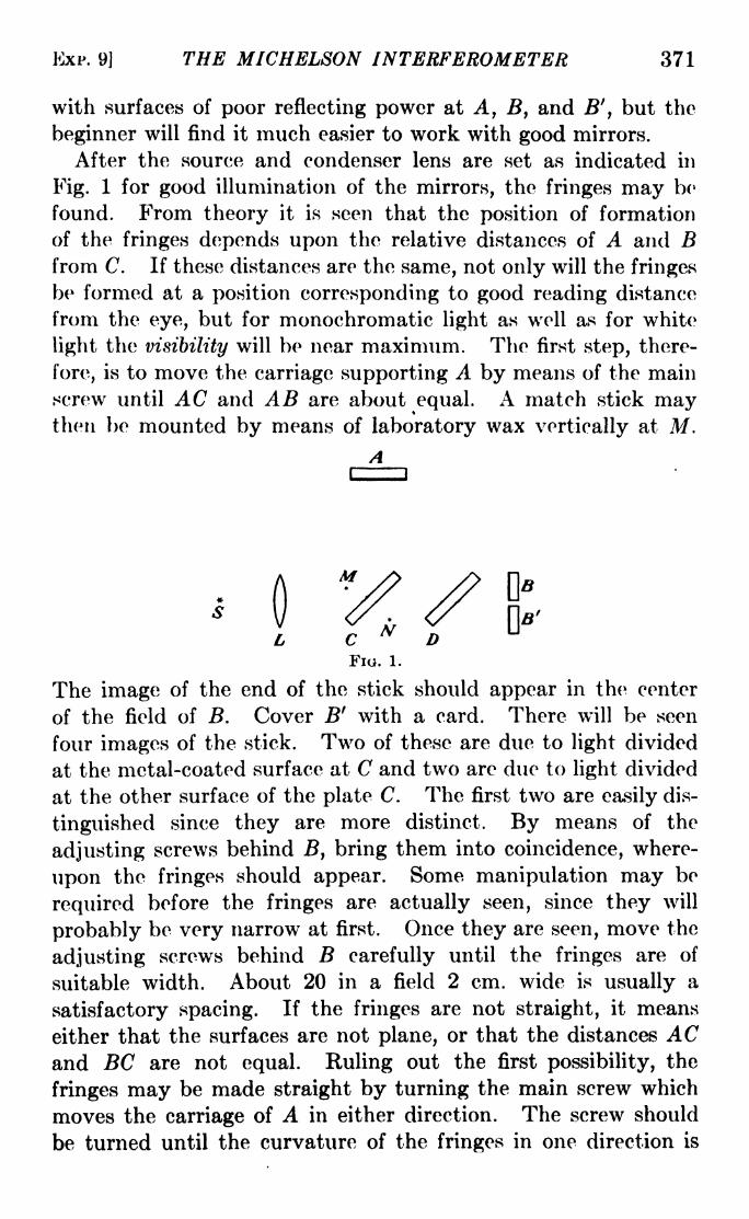
EXP. 9] THE MICHELSON INTERFEROMETER 371
with surfaces of poor reflecting power at A, B, and B', but the
beginner will find it much easier to work with good mirrors.
After the source and condenser lens are set as indicated in
Fig. 1 for good illumination of the mirrors, the fringes may bo
found. From theory it is seen that the position of formation
of the fringes depends upon the relative distances of A and Bfrom C. If these distances are the same, not only will the fringes
be formed at a position corresponding to good reading distance
from the eye, but for monochromatic light as well as for white
light the visibility will be near maximum. The first step, there-
fore, is to move the carriage supporting A by means of the mainscrew until AC and AB are about equal. A match stick maythen be mounted by means of laboratory wax vertically at M.
A
The image of the end of the stick should appear in the center
of the field of B. Cover B' with a card. There will be seen
four images of the stick. Two of these are due to light divided
at the metal-coated surface at C and two are due to light divided
at the other surface of the plate C. The first two are easily dis-
tinguished since they are more distinct. By means of the
adjusting screws behind B, bring them into coincidence, where-
upon the fringes should appear. Some manipulation may be
required before the fringes are actually seen, since they will
probably be very narrow at first. Once they are seen, move the
adjusting screws behind B carefully until the fringes are of
suitable width. About 20 in a field 2 cm. wide is usually a
satisfactory spacing. If the fringes are not straight, it means
either that the surfaces are not plane, or that the distances ACand BC are not equal. Ruling out the first possibility, the
fringes may be made straight by turning the main screw which
moves the carriage of A in either direction. The screw should
be turned until the curvature of the fringes in one direction is

372 LIGHT: PRINCIPLES AND EXPERIMENTS
pronounced and then reversed until the curvature is in the other
direction. The position sought can then be found between
narrow limits. If the fringes change their slope while this is done,the track on which the carriage moves is not clean, and should be
wiped with a clean cloth and a little oil. B' may now be adjustedin the same manner, and a distance in front or behind B of
about 0.1 mm.Different purposes may be served in this experiment, some of
which require more elaborate adjustments than are possible
with the instrument as described. It should be kept in mind,
however, that the procedure is satisfactory, no matter how
simple, if it teaches the student how to manipulate the inter-
ferometer and understand its basic principles. The purpose of
this experiment, therefore, is to assist in the understanding of
the optical phenomena. To demonstrate the accuracy obtain-
able in comparison with that of a micrometer microscope, the
distance between the mirrors B and B' will be measured.
Part A. Comparison of the Measurement of Distance by
Fringe Counting and by a Micrometer Microscope. For this
it will be necessary to have a micro-
meter microscope rigidly attached to
the bed of the interferometer and
focused on a fine line or ruling at right
angles to the motion of A, and on a
plate attached to the carriage of A. A tenth-millimeter scale
ruled on glass may be used.
If B and B' are parallel, the virtual sources with which we
may replace them are indicated in Fig. 2 by the parallel lines
b and 6'. The dotted line a\ is the virtual source which replaces
A when white-light fringes are obtained in A and B. Whenwhite fringes are obtained in the common field of A and B', the
mirror will have been moved through the distance d to a position
indicated by the virtual source a*. This distance can be meas-
ured roughly, (1) by means of the micrometer head on the main
screw which moves A, (2) by the micrometer microscope, and
(3) by counting the number of monochromatic fringes which
pass a point in the field of view. Since the total path distance
introduced by method (3) between B and B' is 2d, we have
2d nX, where n is the number of fringes which pass a given
point in the field.

EXP. 9j THE MICHELSON INTERFEROMETER 373
It is necessary to locate the positions of A for which white-light
fringes are obtained in turn in B and B'. This can be done by the
following steps:
1. Adjust B and B' until the fringes in both are straight, of equal
width, and parallel.
2. Using a white-light source held between the mercury arc and the
interferometer, move A back and forth slightly until the white-light
fringes appear in either B or B'. (There may be some lost motion in the
bearings of the main screw, but the angle of turn required to take this
up may be easily found by observing the monochromatic fringes.)
If white-light fringes are found in B first, and B' is farther away from ('
than B, next move A to correspond to the position of B' and find the
white-light fringes. It should then be possible to move A from one
position to the other two or three times so as to get the corresponding
angle of turn on the micrometer head of the main screw.
3. With the white-light fringes in view in either B or B', take up the
lost motion in the direction which will bring them into the other field.
It is now necessary to establish a fiducial point for counting
fringes. This can be done elaborately in a variety of ways, but
a satisfactory arrangement is a pair of wires, one fixed at Mand one at N (Fig. 1). If the head is kept in a position so that
these two are superposed, there should be no mistake in counting
fringes because of a shift of the point of view. (For persons of
normal vision, or with good accommodation, there will be no
difficulty in seeing the fringes and the wires clearly; for persons
who are farsighted, it may be necessary to mount between the
eye and the interferometer a lens of 15 to 25 cm. focal length.)
Set the moving cross hair of the micrometer microscope on
the ruled line or scratch on the carriage at A, repeating the
setting several times in the same direction, and recording each
observation.
Count the monochromatic fringes which pass as the main
screw is turned slowly until the black central fringe seen in B'
is coincident with the fiducial mark. For slow turning of the
screw there is usually provided an auxiliary worm gear which
can be brought to bear against the edge of the micrometer head.
If the distance between B and B' is 0.1 mm., the number of
fringes of the green mercury line (5.461 X 10~6cm.) which pass
should be about 367.

374 LIGHT: PRINCIPLES AND EXPERIMENTS
Again set the moving cross hair of the micrometer microscopeon the ruled line, which will have been moved, repeating the
setting several times as before. The distance through which the
ruled line and hence the mirror A has been moved should be
n\
where n is the number of fringes counted.
Repeat the count, moving A in the opposite direction.
Also repeat the settings on the ruled line with the micrometer
microscope.
Answer the following questions :
1. Compare the accuracy of your observations by the two methods.
2. In making the preliminary adjustments with the mercury arc, did
you notice some fringes, elliptical in shape, superposed on the fringes to
be measured? If so, attempt an explanation of their origin.
3. Remove the compensating plate D, and look for the white-light
fringes. To what is their appearance due? What do you conclude
regarding the function of the compensating plate?
Part A'. The Use of Circular Fringes. If circular fringes
are used, it will not be necessary to use any fiducial mark, since
these fringes are formed when the mirrors are parallel. Hence,no matter where the eye is placed in the field of view, the fringes
will suffer no changes in diameter. Hence there is no difference
of phase introduced by an accidental shifting of the head. In
this case, it is necessary to count the fringes which appear from
or disappear into the center of the system as one of the mirrors
is moved. It is a little harder to count circular fringes, how-
ever, unless the light is strictly monochromatic, especially whenthe path difference AC BC is small. If the path difference is
small the circular fringes are very large, and for zero pathdifference they cannot be distinguished at all. Under these
circumstances it will be impossible to keep accurate count.
Part B. The Calibration of a Scale. If mirrors B and B'
are mounted on a carriage which may be moved in accurate
ways by a screw in the same fashion as is mirror A, the distance
BB' may be used to step off some other distance which is several
times BB' . This may be done by moving A from coincidence
with B to coincidence with B'}then moving B and B' until B is
EXP. 9] THE MICHELSON INTERFEROMETER 375
once more in coincidence with A, and so on until the full distance
in the larger step is measured. If this larger distance is not an
even multiple of BB', some difficulty is experienced, unless the
remainder can be measured by an independent method. Sup-
pose, for instance, the larger distance is the spacing between two
scale marks on a standard millimeter scale. Then
K = n(BB') + a fraction of BB',
where K is the larger distance, n is the whole number of times
BB' is stepped off. The fraction may be measured in the
manner already described by a count of monochromatic fringes.
Part B'. The Calibration of a Scale. Alternative Method.In case the interferometer is one with only a single mirror at B, a
tenth-millimeter scale may be calibrated with a not excessively
large fringe count. A scale ruled on glass with divisions of 0.1
mm. is recommended. This can be attached to the carriage of A,and extended beyond the bed of the interferometer so that it
may be illuminated from beneath, with a vertical microscope
equipped with a micrometer eyepiece directly above the scale.
It is recommended that a point of light or small source be used,
placed so as to give, in effect, dark-field illumination. In other
words, instead of placing the source directly on the optical axis
of the microscope, place it so that the light diffracted by the
scale divisions is seen in the microscope.
White-light fringes are not needed. Instead, straight fringes
of monochromatic light may be used. The procedure is to set
the moving cross hair of the micrometer microscope on the
image of one of the scale divisions S\. Several settings should
be made and the average of the micrometer readings taken.
Then mirror A is moved until the micrometer cross hair is over
another scale division Sz, the fringes being counted meanwhile.
It is important to realize, however, that bringing the cross hair
of the micrometer microscope into coincidence with Si and $2
in the ways described above are not comparable procedures.
The setting on Si is the average of a number, rapidly made, while
that on Sz can be made only once, since fringes are being counted,
and is then made slowly. Consequently the distance from Si
to Sz measured in this way may be in error. This possibility
of error can be checked by setting the cross hair once more on S*
by turning the micrometer head, making several such settings

376 LIGHT: PRINCIPLES AND EXPERIMENTS
in the identical manner in which the cross hair was formerly set
on Si. Any difference is to be added or subtracted from the
rated scale distance Sz Si. For instance, suppose that whenthe micrometer microscope was originally set on Si the averageof the readings on the head was 87.5, the pitch of the micrometer
screw being 1 mm. That when the corrective setting was
finally made on Sz, the average of the readings on the head
turned out to be 88.8. The difference in the settings is 0.013 mm.This amount is to be added to or subtracted from the rated dis-
tance between Sz and Si, depending on whether increased readingson the head correspond to an advance of the cross hair toward
$2 or a motion back toward Si.
Another method which may be successful if it is practiced
before the experiment is under way is as follows: Start counting
fringes a little before the cross hair reaches Si, and when the
observer at the microscope decides the cross hair is just on *Sj,
note the extent of the count. Also, continue counting a little
after the cross hair is seen to reach S%. If HI is the number in
the count as the cross hair passes Si, and w2 is the number in the
count as it passes $2, then n2 n\ is the number of fringes
corresponding to Sz S\.
(Sz -Si)=
(rh HI) =
Obviously, if the rated distance Sz Si is known accurately,
the wave-length of the light may be found, instead of the scale
being calibrated.
EXPERIMENT 10
MEASUREMENT OF INDEX OF REFRACTION WITHA MICHELSON INTERFEROMETER
Theory. If a plane-parallel plate of index of refraction n is
inserted normal to the path of one of the beams of light traversing
the arms of a Michelson interferometer, the increase of optical
path introduced will be 2(n l)t, where t is the thickness of the
plate. The factor 2 occurs because the light traverses the plate
twice. For monochromatic light of wave-length X, the difference
of path introduced is N\, where N is the number of fringes dis-
placement introduced when the plate is inserted. Hence, if a
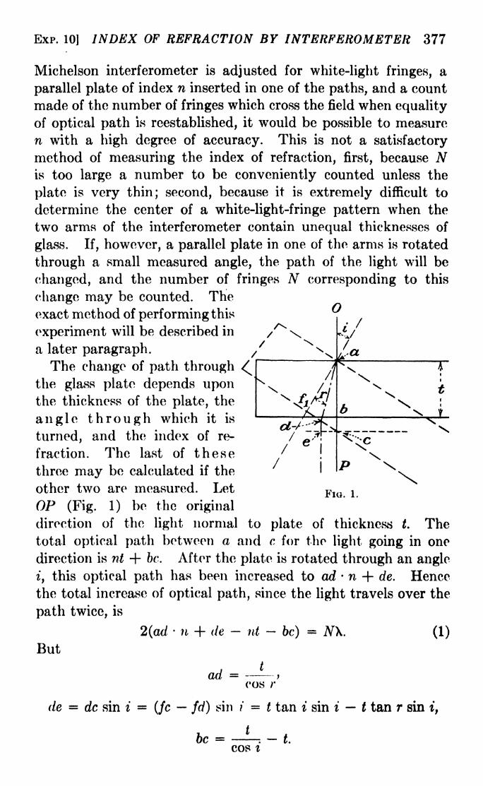
EXP. 10] INDEX OF REFRACTION BY INTERFEROMETER 377
Michelson interferometer is adjusted for white-light fringes, a
parallel plate of index n inserted in one of the paths, and a count
made of the number of fringes which cross the field when equality
of optical path is reestablished, it would be possible to measure
n with a high degree of accuracy. This is not a satisfactory
method of measuring the index of refraction, first, because Nis too large a number to be conveniently counted unless the
plate is very thin; second, because it is extremely difficult to
determine the center of a white-light-fringe pattern when the
two arms of the interferometer contain unequal thicknesses of
glass. If, however, a parallel plate in one of the arms is rotated
through a small measured angle, the path of the light will be
changed, and the number of fringes N corresponding to this
change may be counted. Theexact method of performing this
experiment will be described in
a later paragraph.The change of path through
the glass plate depends uponthe thickness of the plate, the
angle through which it is
turned, and the index of re-
fraction. The last of these
three may be calculated if the
o
/ \\FlQother two are measured. Let
OP (Fig. 1) be the original
direction of the light normal to plate of thickness t. Thetotal optical path between a and c for tho light going in one
direction is nt + be. After the plate is rotated through an angle
i, this optical path has been increased to ad - n + de. Hence
the total increase of optical path, since the light travels over the
path twice, is
2(ad- n + de - nt - be}
= N\. (1)
But
Aadcos r
de = dc sin i (jc fd) sin ? = t tan i sin i t tan r sin i,
hr t\J\s ~. (/
COS I

378 LIGHT: PRINCIPLES AND EXPERIMENTS
So,
nt . . , ... , , . . . t N\----\- i t an i sin i t tan r sin i nt ----: -\- t = -^r--
cos r cos i 2
Using Snell's law, n sin r = sin i, this may bo reduced to
n(l- cos 02* - ArX =
(2t-
iVX)(l- cos + ^-- (2)
Since the last term is small compared to the others, it may be
neglected, leaving for the index of refraction
(2t- N\)(l - cosQ
27(T- cos - '
^ }
In the experiment, two such plates, PI and P%, are used, one in
either arm of the interferometer. These are made only half as
high as the mirrors A and B so as to permit the observation in
the field of view above them of fringes unaffected by the changeof angle i. The use of two plates insures equal optical pathsin the two arms, at all times when the angles of these plates
with the direction of the light beams are the same, making
possible the observation of white-light fringes through the plates
when they arc tilted at the same angle with the beam.
First, by the method outlined in Experiment 8, obtain in the
upper part of the field vertical white-light fringes. This had
better be done with the half plates Pi and Pz already in place,
as inserting them afterward may be the cause of an accidental
displacement of the other parts of the interferometer. With
the white light fringes obtained, next set Pi and PZ normal to
the light path as nearly as can be done while looking down on the
instrument. Then, while observing the fringes, turn PI slowly
until the fringes appear also in the lower part of the field. Nowobserve what happens if half plate P 2 is rotated a slight amountin one direction. If the lower fringes move completely out of
the field and do not return, rotate P2 in the other direction.
What will usually happen is that either in turning one way or the
other the fringe system will be displaced a number of fringes, say,
to the right, and then move in the opposite direction. This
indicates that the half plate Pi was not, in the rough adjustmentof the plate normal to the light path, set normal with sufficient
precision. Hence it is to be rotated by such an amount that

EXP. 10] INDEX OF REFRACTION BY INTERFEROMETER 379
eventually the white-light fringes in the lower part of the field
will move continuously out of the field in one direction upon a
turn of Pz in one sense, and out of the field in the same direction
with a turn of PZ in the opposite sense, without returning in
either case. If the half plates PI and PI are cut from the same
parallel plate, i.e., are of exactly the same thickness, the white-
light fringes should coincide in the upper and lower parts of the
field.
Sometimes it is impossible to obtain the adjustment described
in the preceding paragraph. This may be due to the fact that
one of the half plates is "leaning" slightly in its frame, a con-
dition which may be corrected by rocking the plate slightly.
Another reason for lack of adjustment may be that the half
plates are not cut from a parallel plate, but from one which has a
slight wedge shape, the two sides being out of parallelism by a
fringe or two. In this case the fringes in the upper and lower
parts of the field of view of the interferometer may not be
parallel, and one of the plates should be turned over in its frame.
After the white-light fringes extend across both the upper and
lower portions of the field, and the half plates are precisely
normal to the beams, turn P\ through an angle of about 15 deg.
This should be done in the direction in which the last adjustmentof that plate was made, so that there is no lost motion to be
taken up. (If no micrometer attachment is available for deter-
mining exactly the angle that P\ is turned through, a small
mirror fastened to the cell for Pi and facing in the direction of a
telescope and scale placed about 6 ft. away may be used. The
angle will then be measured in the conventional manner with the
telescope and scale.) Having turned Pi, and measured its
angle, slowly turn Qz through the same angle, meanwhile count-
ing fringes to the number (N) of monochromatic light which
pass a selected point in the field, until the white-light fringes
reappear in the lower part of the field and coincide with those
in the upper. For this purpose, the green line of mercury maybe used, and a source of white light be held or clamped in such a
way that part of the field is illuminated by it. Thus the mono-
chromatic fringes may be observed to pass, and at the same time
the white-light fringes will be detected when they appear. Anexcellent check on the value of N is then to turn P2 in the opposite
direction, meanwhile counting fringes, until the white-light

380 LIGHT: PRINCIPLES AND EXPERIMENTS
fringes once more appear in coincidence. P-t will then have been
turned through twice the angle i, and the number of fringes in
this second count should be 2N.
Remove Pz and measure its thickness t with a micrometer
caliper. Then calculate the value of n, using cq. 3.
Answer the following questions :
1. What percentage of error is introduced in the measurement of the
index of refraction by an error of 10 min. of arc in the measurement of
the angle through which Pa is turned from the normal position?
2. What percentage of error is introduced in the measurement of the
index by an error of 0.005 mm. in the thickness of /Y?
3. What percentage of error is introduced in the measurement of the
index by an error in the count of N of five fringes?
4. Would any appreciable improvement in the result be obtained by
retaining the last term in eq. 2?
EXPKRIMP;NT 11
THE RATIO OF TWO WAVE-LENGTHS WITH THEMICHELSON INTERFEROMETER
Read Sec. 11-7 for the discussion of visibility fringes.
Apparatus. A Michelson interferometer, a mercury arc, a
filter of didymium glass about 5 mm. thick, aqueous solutions of
copper nitrate, cobalt sulphate, and nickel acetate, an assortment
of gelatin filters, a condensing lens. Uranine may be substi-
tuted for the solution of cobalt suphato.
Part A. The solutions are to be prepared of sufficient densityso that the combined filter will permit the transmission of only
X4358 and X5461. It is essential that these be of about the same
visual intensity. The transmission of the filter can be tested
with a direct-vision spectroscope or a spectrometer and 60-deg.
prism. Of the stronger mercury lines, copper nitrate transmits
only those from X4046 to X5790, inclusive. Nickel chloride
cuts out X4046 and X4071. Didymium glass cuts out X5770
and X5790, and cobalt sulphate or uranine cuts out the faint
green line X4916. These solutions may be mixed together in a
filter cell about 1 cm. thick, or better still, in separate cells. If
there is any precipitate present, the addition of a little hydro-chloric acid will remove it.
Adjust the interferometer for white-light fringes. With the
mercury arc and the combined filter the succession of maxima
EXP. 11] THE RATIO OF TWO WAVE-LENGTHS 381
and minima will be clearly seen. Count the number of fringes
from the minimum closest to the center of the white-light patternto the thirtieth minimum away. Obtain by division an averagenumber of fringes N between any two consecutive minima. Nwill not necessarily be a whole number. The ratio of the two
N Iwave-lengths will be given by ^ Since this ratio is so far
from unity, N being small, it will be necessary to try both the
positive and negative signs.
Part B. Remove the didymium glass and substitute a filter
which transmits only X5770 and X5790. This may be composedof an orange gelatin filter with an aqueous solution of cobalt
sulphate. Since the two wave-lengths are almost the same,
many fringes (between 200 and 300) must pass the field of view in
passing from one position of maximum visibility to another.
Moreover, at minimum visibility the counting of the fringes will
be impossible or nearly so. Instead it will be necessary to rely
on the accuracy of the main screw which moves the carriage.
First calibrate the screw by turning the micrometer head
through about one-tenth of a turn, counting the fringes mean-
while. Then set for the first position of minimum visibility
next to the position of zero path difference, and read the microm-
eter. Turn the screw until the twentieth minimum comes into
the field, keeping track meanwhile of the total number of turns
of the screw. The fractional part of a turn may be read from the
micrometer. The total number of fringes which have passed
may thus be calculated.
Since the screw may not possess an accuracy warranting
this calculation, an alternative method is suggested as a check.
Substitute a filter transmitting only the green line of mercury,and turn the screw through exactly one revolution, counting
fringes meanwhile. This will determine the pitch of the screw.
(If this is already accurately known, the foregoing will not
be necessary.) Then, if, say, the screw wap turned through
3.32 turns in passing from one minimum of visibility to a distant
one for X5770 and X5790, since the distance moved is equal to
ATX/2, we have
2 X 3.32 X 0.05 = N0.0000578
382 LIGHT: PRINCIPLES AND EXPERIMENTS
where the pitch of the screw is taken as 0.05 cm. and the average
wave-length is used. In the example, the number of fringes is
about 5743, corresponding to the passage from a given mini-
mum to the twenty first from it. Hence 5743/21, or 273.48
fringes would pass in going from one minimum to the next, and
273.48/274.48 is the ratio of the wave-lengths. For the accuracy
possible it is not material whether in (N 1)/AT the -f- or
sign is used. Assuming the correct value for the longer wave-
length to be 5790.66, the value for the shorter becomes 5769.56.
The correct value is 5769.60.
EXPERIMENT 12
THE FABRY-PEROT INTERFEROMETERIn the discussion of the theory of this instrument in Sec. 8-11
it has been pointed out that the use of multiple beams instead of
double beams to produce interference results in a great decrease
in the width of the interference maxima. Thus the observer is
permitted to see, distinctly separated, the interference fringes
due to two or more radiations. Since, however, for each mono-
chromatic radiation, the interference pattern consists of a, set-
of concentric rings, there is no direct method of finding out which
of two wave-lengths may be the larger. For instance, in the
interference pattern of the complex mercury line A = 5461 illus-
trated in Fig. 11-17, it is not immediately possible to say whether
the faint fringes shown are of shorter or longer wave-length
than the brighter ones. If, however, however, two radiations
already well known are used, the ratio of their wave-lengths
may be found.
Apparatus. A Fabry-Perot interferometer with one plate on a
movable carriage so that it may be moved perpendicular to its
face by means of a screw, a mercury arc, a condensing lens, and a
filter transmitting only 5770 and 5790 angstroms.
Since the sharpness of the fringes depends on the number of
reflections between the two plates, care should be taken to see
that the reflecting coats are as bright as possible. Aluminum
deposited on the plates by evaporation is exceedingly durable.
The coats of metal should be much thicker than half coats in
order to insure high reflecting power. Care should be taken to
see that the ways in which the carriage moves are clean and free
from dust.

EXP. 12] THE FABRY-PEROT INTERFEROMETER 383
In finding the fringes, which are circular, it is best to have the
separation between the mirrors as small as possible, since then
the diameters of the innermost fringes are very large.
Do not jam the mirrors together.
Set up the mercury arc and condensing lens so that the entire
area of the plates is well illuminated. Hold a pencil or matchstick between the rear mirror and the lens, and manipulate the
adjusting screws in front of the interferometer until the manifold
images of the stick coincide. The fringes will then be seen,
probably poorly defined and as if astigmatic. Careful adjust-
ment is then made by turning the screws, which change the tilt
of the fixed mirror, meanwhile observing whether the diameters
change as the eye is moved from side to side and up and down.
If on moving the eye to the left, the circles become larger, the
distance between the mirrors on the left is greater than that on
the right, and further adjustment should be made. In this
manner, get the two mirrors as nearly parallel as possible. Thenrun the movable carriage back a few millimeters and see if the
parallelism is lost. If, to any appreciable extent, it is, the waysmust be cleaned again or other necessary steps taken to improvethe mechanical performance.Next insert the filter transmitting only the two wave-lengths
to be observed. A tentative turn or two of the main screw will
show that, as the carriage moves, single and double fringes
alternate. If the metallic coatings are not very thick, the
resolving power will be less, and instead of definite doubling of
the fringes, there will be simply a decrease in visibility of the
interference pattern.
The radius of any circular fringe increases as the mirrors are
moved apart, and decreases as they are brought together. Abright fringe for a given wave-length \i has a radius which
depends on the separation of the mirrors, the orders of inter-
ference of the fringe, and the wave-length, as given by the
equation
2e cos i = PiXi,
where e is the separation of the mirrors, Pi is the order of inter-
ference, or number of wave-lengths difference of path between
two interfering beams, and i is the angle subtended by the radius
of the fringe. Hence, if there is another longer wave-length \2

384 LIGHT: PRINCIPLES AND EXPERIMENTS
whose fringes have the same radii as Xi, i.e., if the fringes for the
two are exactly superposed, then
2e cos i = P2\2.
As the distance between the two mirrors is increased, in passing
from one position of coincidence to the next, the change in NZwill be one less than the change in N\. Hence, if N is the numberof fringes which appear at the center of the pattern as the distance
is increased, then
(N -1)X, = #Xi.
Actually, the wave-lengths are so nearly alike that it is not
possible to tell which set of fringes belongs to the longer, and the
procedure is to count the number of fringes which appear at the
center between two successive coincidences (or maxima of
visibility) and obtain the ratio of the wave-lengths by the equation
X, N 1
X2 NIf one of the wave-lengths is known, the other may be calcu-
lated. Determination of the point at which the fringes are
exactly superposed is difficult. However, the error in this
determination can be reduced by counting from one maximumor point of superposition to the fifth or sixth from it, and obtain-
ing a mean value for N. An alternative procedure is to count
from the position of minimum visibility instead. If the fringes
are very sharp, this will correspond to the position where the
two sets are midway between each other, with dark rings of
equal width and blackness between them.
EXPERIMENT 13
MEASUREMENT OF WAVE-LENGTH BY DIFFRACTIONAT A SINGLE SLIT
For the theory of diffraction by a single slit, see Sec. 12-8.
It is evident from eq. 12-5 that the intensity obtained bydiffraction of light through a single slit becomes zero for values
of <p m/a, where a is the width of the slit and m is an integer.
Since <p sin i sin 0, satisfactory experimental conditions
will exist if i is made zero, so that sin 6 m/a. It must be
remembered, however, that eq. 12-5 is based on the assumption

EXP. 13] WAVE-LENGTH BY DIFFRACTION 385
that the light illuminating the slit is collimated, so that the
pattern is one obtained by Fraunhofer diffraction.
Apparatus. A spectrometer, a mercury arc, a filter for the
transmission of the green mercury line 5461 angstroms, an
auxiliary slit. (In case a spectrometer is not available for this
experiment, satisfactory results may be obtained if the primary
slit, upon which the light of a mercury arc is focused through a
filter, is placed at a distance of about 20 ft. from a laboratory
telescope, which has an auxiliary slit fitted over its objective.
The telescope must be capable of rotation about a vertical axis,
and there must be provided also some method for measuringthis rotation to an accuracy of about 5 sec. of arc. The use of a
spectrometer is advised.)
If a filter transmitting only the green line is not available or
if its use dims the light too much, the light from the collimator
may first be passed through a prism, and thereafter the greenline allowed to fall upon the auxiliary slit.
With a spectrometer correctly focused so that an image of the
primary slit is at the plane of the cross hairs, and a satisfactory
filter, or prismatic dispersion, set the auxiliary slit with its jawsat the center of the spectrometer table so that the plane of the
jaws is perpendicular to the beam of light from the collimator.
Adjust the width of the auxiliary slit so that the fringes are dis-
tinct and of measurable width. Frequently there is difficulty in
getting sufficient light intensity to permit accurate settings on the
diffraction minima. In this case it is not good practice to openthe primary slit at the source end of the collimator too wide, since
this results in a blurring of the pattern. The primary slit
should be closed to as small dimensions as will afford good
visibility of the fringe pattern. Proper shielding of the instru-
ment from extraneous light, and allowing time for the eye to
become accustomed to conditions, will be of advantage.
It is recommended that before observations are begun, the
auxiliary slit be removed carefully and its width measured bymeans of a micrometer microscope or comparator. This may be
done afterward, but in case there is any danger of altering the
slit width by moving it, time will be saved by finding it out at the
start.
The quantities to be measured are the width a of the auxiliary
slit and the angle between two successive minima. Since the

386 LIGHT: PRINCIPLES AND EXPERIMENTS
angle to be measured is very small, sin 6 may be put equal to 6, so
that = w/a, from which 6 may be calculated. The easiest
settings to make are obviously those on minima which are close
to the middle of the pattern where the intensity is greatest.
However, increased accuracy may result if as many minima as
possible are measured, and a weighted mean of the resulting
value of be found. If the light is not too faint, it should be
possible to set on eight or ten minima on either side. In case
difficulty is experienced in seeing the cross hairs when they are
set on minima, flashing a utility light of low brightness into the
telescope will help.
As in other experiments, there should be several settings madefor each position of the telescope, and the mean taken in each
case. It is possible to obtain a final average value of B by simply
subtracting the mean value of each setting from the mean value
of the next contiguous one, thus obtaining several values of 6
which may be averaged. It should be pointed out, however, that
the result thus obtained is not the mean of independent observa-
tions. Furthermore, the observations are not of equal weight.
A better practice is to subtract the setting on the first minimumon one side from the first minimum on the other side of the
central image, yielding a value twice 0, and assign to it a weight
of 2; then subtract the setting on the second minimum on the
one side from the setting on the second minimum on the other
side, yielding a value four times 0, with a weight of 4, and so on,
as far out as minima can be distinguished. This practice of
weighting, however, which assumes that all the observations are
of equal difficulty, should be modified in the present case since
the minima become progressively more difficult to distinguish
as one goes further out from the center of the pattern. The
following modification is suggested. Suppose the settings on the
two seventh minima are as follows :
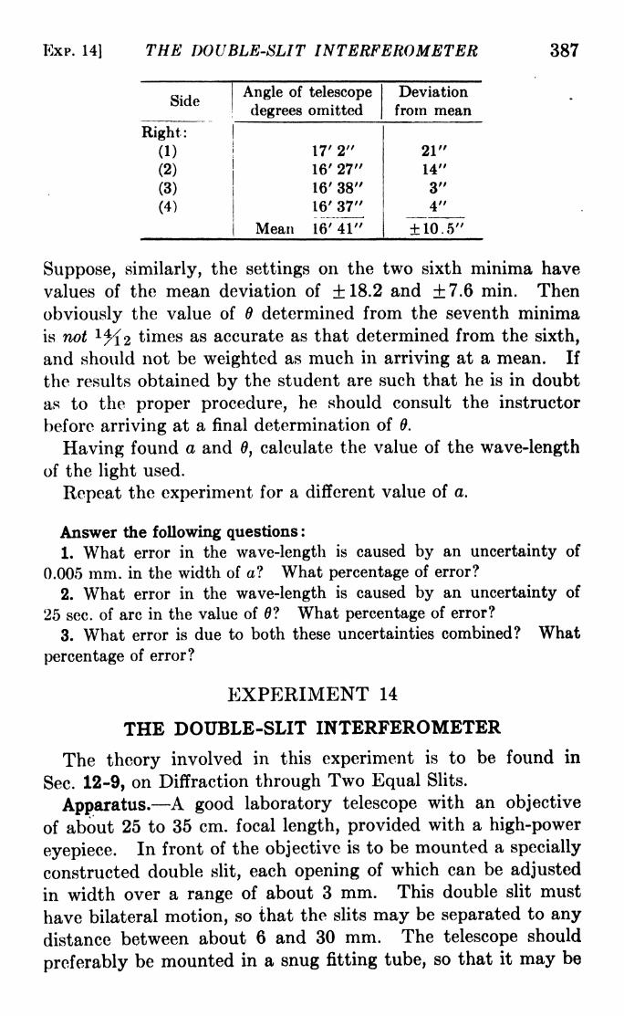
EXP. 14] THE DOUBLE-SLIT INTERFEROMETER 387
Suppose, similarly, the settings on the two sixth minima have
values of the mean deviation of 18.2 and +7.6 min. Then
obviously the value of 6 determined from the seventh minima
is not l%2 times as accurate as that determined from the sixth,
and should not be weighted as much in arriving at a mean. If
the results obtained by the student are such that he is in doubt
as to the proper procedure, he should consult the instructor
before arriving at a final determination of 9.
Having found a and 6, calculate the value of the wave-length
of the light used.
Repeat the experiment for a different value of a.
Answer the following questions :
1. What error in the wave-length is caused by an uncertainty of
0.005 mm. in the width of a? What percentage of error?
2. What error in the wave-length is caused by an uncertainty of
25 sec. of arc in the value of 0? What percentage of error?
3. What error is due to both these uncertainties combined? What
percentage of error?
EXPERIMENT 14
THE DOUBLE-SLIT INTERFEROMETER
The theory involved in this experiment is to be found in
Sec. 12-9, on Diffraction through Two Equal Slits.
Apparatus. A good laboratory telescope with an objective
of about 25 to 35 cm. focal length, provided with a high-power
eyepiece. In front of the objective is to be mounted a specially
constructed double slit, each opening of which can be adjusted
in width over a range of about 3 mm. This double slit must
have bilateral motion, so that the slits may be separated to any
distance between about 6 and 30 mm. The telescope should
preferably be mounted in a snug fitting tube, so that it may be

388 LIGHT: PRINCIPLES AND EXPERIMENTS
rotated about its axis, in order to adjust the double slits to a
vertical position. If this is not feasible, the double slit should
be rotatable. A single slit to be used as a source, accurately
round pinholes, filters, and a mercury arc are also needed. Arotatable biprism is necessary for Part E, in case that part is done.
Adjustments. Set the single slit in a vertical position, and
illuminate it with a mercury arc, provided with a filter to permit
the passage of the green line X5461. An image of the arc must
be projected on the slit, so that the latter is truly a source with
respect to the observing telescope. The single slit and the double
slits must be vertical, or at least parallel to each other.
It will be necessary to adjust the width of the single slit so that
the resulting interference pattern can be made to disappear (or
reach a minimum visibility) within the range of motion of the
double slit. Obviously, from the equation
l\w=d'
in which w is the slit width, and I the distance between the source
slit and the telescope, a rough preliminary calculation of the
most desirable value of w will save a great deal of time. For a
value of I of about 8 m. and a separation d of the double slits of
about 1.5 cm., w would be about 0.3 mm.The double slits should be equal in width. A suitable width,
for other dimensions given, is about 1 mm., although a smaller
width can be used if there is sufficient light intensity. A greater
width will, of course, result in a more brilliant image, but the
diffraction pattern from each slit will be narrower, and the
number of fringes in the brightest portion of the image will be
less. When the telescope is correctly focused, the image seen
in the eyepiece will be similar to the two-slit diffraction patternseen in Fig. 12-146, except that there will usually be more and
narrower interference fringes. As will be seen from the theory,
the number and spacing of the interference fringes will depend
upon the ratio of the common width of the double slits to the
width of the opaque space between them.
Part A. With proper illumination on the slit, and the maxi-
mum intensity of the cone of light directed to the telescope,
adjust the source slit to a width between 0.2 and 0.3 mm. Focus
the telescope on the slit and mount the double slit in front of the

EXP. 14] THE DOUBLE-SLIT INTERFEROMETER 389
objective, so that the source slit and the double slits are parallel.
Fringes should be seen. Beginning with the widest separation,
slowly reduce the separation of the double slits until the fringes
disappear. Record the distance from center to center of the
double slits at this point, and continue narrowing the separation
until the last disappearance is observed. It is sometimes
difficult, especially for the beginner, to detect the point of
disappearance, because (a) the slit source may be slightly
wedged-shaped, in which case disappearance will not occur
simultaneously along the fringes; (6) the fringes are so narrow
that they are indistinct; (c) the two slits are not of the same
width, and only a minimum visibility is attained. In case of
failure to observe disappearance or to identify it as a first-order
disappearance, the theoretical separation d of the double slits maybe approximately calculated by eq. 1, to aid in the observations.
White light may be used instead of the mercury arc, since the
order of interference is quite small. In this case, in the calcula-
tion of w from eq. 1, the value of X to which the eye has maximum
sensitivity should be used. For most eyes this is between
5.5 X 10~5 and 5.7 X 10~5 cm. Make several determinations
of d and I and calculate w and the mean error of observation.
Measure the width of the single slit carefully with a microm-
eter microscope, a traveling microscope, or a comparator, repeat-
ing the measurements for different places on the slit. Replace
the single slit in its former position in the optical train.
Part B. Set the double slit at a separation of about 1 to 2 cm.
and vary the width of the single slit slowly, observing the succes-
sive widths for which the fringes disappear. For this purpose
it is desirable that the slit be equipped with a micrometer head
for quick reading. If this is not available, the width for each
disappearance must be measured as before. The widths observed
should be multiples of some value which, within experimental
error, will be the value of w obtained in Part A. The allowable
error of the experimental determination of w by observation
of the disappearance of the fringes in Parts A and B is between
2 per cent and 8 per cent, depending upon the care and skill of
the operator and the precision of the mechanical parts.
Part C. Remove the double slit and the eyepiece and substi-
tute a micrometer eyepiece. Can you measure the width of the
slit? If so, with what accuracy? What limits the accuracy in

390 LIGHT : PRINCIPLES AND EXPERIMENTS
this case? Compare the accuracy of this measurement with
the ones made in Parts A and B.
Part D. Remove the single slit and substitute a pinholein a thin metal sheet. Use white light for greater intensity. In
this case the angular diameter is given by 1.22\l/d, when the
fringes disappear.
Part E. Place the rotable biprism over the pinhole so that
the two images seen through the biprism just touch edges whenviewed through the telescope without the double slit. Replacethe double slit, orient it to the angle of the biprism, and measure
the separation of the two virtual images by the disappearanceof the fringes as before. The distance between the centers of
the two virtual images of the pinhole is given by a =0.61XZ/*/.
Repeat Part C for this source.
EXPERIMENT 15
THE DIFFRACTION GRATING
The theory of this experiment is to be found in Sec. 12-12.
Apparatus. A spectrometer, a mercury arc, a helium dis-
charge tube, a plane diffraction grating of the reflection type, a
Gauss eyepiece. If only a transmission grating is available, the
following procedure must be modified slightly.
Adjust the spectrometer as directed in Appendix IV. Place
the mercury arc in front of the slit, which may be opened to a
width of about 0.5 mm. By looking at the face of the collimator
lens, make sure that the entire lens is filled with light. Set the
grating on the spectrometer table so that (a) its plane contains
the main vertical axis of the spectrometer, (6) the cone of light
from the collimator is centered on the ruled area of the grating,
(c) the rulings are parallel to the axis of the spectrometer, (d)
the slit is parallel to the rulings.
Adjustments for (a) and (6) may be initially made by simple
inspection, with the telescope swung out of the way. To insure
that the axis actually lies in the surface, the Gauss eyepiece
method may be used. Assuming that the telescope is in adjust-
ment so that its axis cuts, and is perpendicular to, the axis of the
spectrometer, the latter will be parallel to the grating surface
when the image of the cross hairs reflected from the surface of
the grating coincides with the cross hairs themselves.

EXP. 15] THE DIFFRACTION GRATING 391
Before making adjustment (c), fasten a wire or match across
the middle of the slit, and set the spectrometer table so that the
angle of incidence is between 50 and 60 deg. Then each line
of the spectrum, in as many orders as can be reached on both
sides of the central image (direct reflection), should be examined
through the telescope. When the middle of the slit stays the
same height in the field of view, the rulings are parallel to the
axis.
Before attempting adjustment (d), ascertain whether the slit
is in a fixed position, or if it may be rotated. If the former is the
case, do not risk damaging it by forcing rotation. If rotatable
about the axis of the collimator, turn it until the image of the
obstacle is sharpest; then the slit will be parallel to the
rulings.
At this point it is well to caution the student that precise
adjustments and observations are not possible unless the telescope
is properly focused on the spectrum lines. Remember also
that even if the instrument is fitted with so-called achromats, the
focal lengths will not be the same for all wave-lengths. It is also
well to find out if the grating has Rowland or Lyman ghosts.l If
these exist, they should be ignored in making the observations.
Before continuing, narrow the slit until the lines are as sharp
as possible. This stage will be reached when closing the slit
further makes no apparent change in the width of a line but
simply a reduction in the intensity.
Part A. With the foregoing adjustments made, next find the
setting in angle on the circle of the spectrometer, (a) when the
telescope is normal to the grating, (6) when the central image
(direct reflection) is on the cross hairs, (c) when each strong
line of the mercury spectrum, in each order which can be reached,
is on the cross hairs. Tabulate these data. In the first column
put the order of the spectrum; in the second, the wave-lengths;
in the third, the angles. From settings (a), (6), and (c) the
values of i and 6 may be found and put in columns four and
five. The grating equation is
1 Rowland ghosts are false images of a spectrum line, grouped symmetric-
ally on both sides of the line; they are usually faint in low orders. Lyman
ghosts are false orders of spectra occurring at angles for which m is not a
whole number (see eq. 1). Both types are due to irregularities in the ruling
of the grating.
392 LIGHT: PRINCIPLES AND EXPERIMENTS
'i /> fH\ , ., x
sin z + sin 6 = T-> (1)
in which i is the angle of incidence, the angle of diffraction, m the
order, X the wave-length, and d the grating space. From eq. 1
and the observed data, the wave-lengths of the lines may be
calculated if the grating space is known, or vice versa. The nega-tive sign is used when the spectrum is on the same side of the
normal to the grating as the central image.Part B. Resolving Power. Since ft = X/dX when the limit
of resolution is reached, the resolving power is found by deter-
mining the limit of resolution which, according to Rayleigh's
criterion, is reached when two spectrum lines are a distance apartsuch that the central maximum of the diffraction (or interference)
pattern of one line falls upon the first minimum of the other.
With the particular grating used, it would be difficult to find two
spectrum lines which just fulfill this requirement. Moreover, it
is essential that the entire grating be uniformly illuminated.
The procedure is, then, to find the resolving power r of a small
width w of the grating, and calculate R for the entire grating
from the relation
if _ entire width W of grating
width w illuminated to obtain r'
In order to use only a small portion of the grating, place over
the telescope lens an auxiliary slit. When this is closed to a
width a, the value of w is given by w = a/cos 0.
At this stage the student should make sure that he has a
satisfactory source of a close pair of lines. For moderately low
resolving power the yellow doublet of mercury at 5770 and
5790 angstroms is suitable, but if the grating has rulings as
close as, say, 5000 to the centimeter, its resolving power will be
so high that the auxiliary slit width must be very small. For
the ordinary reflection grating, therefore, the sodium doublet
at 5890 and 5896 angstroms is 'most satisfactory. There are
many sources of this light, perhaps the most brilliant being that
obtained when an oxygas flame is trained on a small piece of
pyrex tubing held on an iron rod about ^ in. in diameter. If
oxygen is not available, a well-adjusted air-gas flame and soft
glass tubing will do.

EXP. 15] THE DIFFRACTION GRATING 393
With the proper source in operation in front of the first slit,
close down the auxiliary slit until the two lines of the doublet can
just be observed separately. Make several trials. Carefullyremove the auxiliary slit and measure its width a with a microm-eter microscope. Find and calculate w.
The resolving power of a grating is given by
It = mn, (3)
where m is the order, and n is the total number of rulings. Fromthe known value of the grating space and the measured value
of w calculate r. Then find R from eq. 2. Compare this
with the value of R given by the definition of resolving power:R = X/dX (when the limit of resolution is reached).
Part C. Dispersion. This is defined as D = dQ/d\. Calcu-
late Z> from the values of 6 for two close lines such as the mercury
yellow lines, and compare it with D obtained from
D= md cos 6
Discuss the errors and their probable origin, in your determina-
tions of the wave-lengths.
Part D. The Transmission Grating. The foregoing direc-
tions are for a reflection grating of fairly high dispersion. In
case only a transmission replica is available, the directions will
apply with slight modifications. Instead of the angle of the
direct reflection, that of the transmitted beam, i.e., at 180 deg.
from the collimator setting, must be used. Also, in eq. 1 the
positive sign is used if the diffracted light is on the same side
of the normal as the incident beam. Other modifications may be
suggested by the instructor.
Part E. The Concave Grating. In case only a concave grat-
ing is available, essentially the same quantities may be found
by experiment, but the procedure will be quite different, depend-
ing on the type of mounting used. There are three general
ways of mounting a concave grating:
a. The Rowland Circle. If light is incident at an angle i
with the normal to the grating, then the position of the astigmatic
spectral line is given by the equation for the primary astigmatic
focus (eq. 6-8), with 6, the angle of diffraction, substituted for
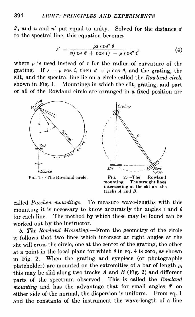
394 LIGHT: PRINCIPLES AND EXPERIMENTS
i', and n and ri put equal to unity. Solved for the distance s1
to the spectral line, this equation becomes
ps cos'2
s(cos -f- cos i) p cos 2 i(4)
where p is used instead of r for the radius of curvature of the
grating. If s = p cos i, then sf = p cos 0, and the grating, the
slit, and the spectral line lie on a circle called the Rowland circle
shown in Fig. 1. Mountings in which the slit, grating, and partor all of the Rowland circle are arranged in a fixed position are
Grating
* Source
FIG. 1.- -The Rowland circle.
Slit _holder
FIG. 2. -The Rowlandmounting. The straight lines
intersecting at the slit are thetracks A and B.
called Paschen mountings. To measure wave-lengths with this
mounting it is necessary to know accurately the angles i and 6
for each line. The method by which these may be found can be
worked out by the instructor.
b. The Rowland Mounting. From the geometry of the circle
it follows that two lines which intersect at right angles at the
slit will cross the circle, one at the center of the grating, the other
at a point in the focal plane for which in eq. 4 is zero, as shown
in Fig. 2. When the grating and eyepiece (or photographic
plateholder) are mounted on the extremities of a bar of length p,
this may be slid along two tracks A and B (Fig. 2) and different
parts of the spectrum observed. This is called the Rowland
mounting and has the advantage that for small angles 0' on
either side of the normal, the dispersion is uniform. From eq. 1
and the constants of the instrument the wave-length of a line

EXP. 16] SIMPLE POLARIZATION EXPERIMENTS 395
exactly on the normal may be found, after determining i and 8.
This may be repeated for each line, or else the dispersion may be
found for a small region near the normal, and an interpolationmethod used.
c. The Eagle Mounting. Sometimes it is convenient to set
the grating so as to utilize the diffracted light which is returned
directly back along the same path as the incident beam, or
nearly so, as shown in Fig. 13-35 for a prism instrument. This
type of mounting is little used except for photographic spectro-
scopy. In case it is necessary to use it for visual determinations
of wave-length, it is recommended that Baly, "Spectroscopy,"Vol. I, be consulted.
EXPERIMENT 16
SIMPLE POLARIZATION EXPERIMENTS
The theory of this experiment is to be found in Chap. XIII.
Apparatus. A polariscope1 of design similar to that supplied by
the Gaertner Scientific Co., illustrated in Fig. 1, a white light
with diffusing bulb, a monochromatic source such as a mercuryarc and filter for X5461, or a sodium burner (which need not be
very bright), a supply of the polarizing materials mentioned in
the directions given below.
Procedure. 1. Make a dot on a piece of white paper and over
it place a rhomb of calcite 1 cm. thick or more. Rotate the
rhomb and identify the o- and e-rays. Which travels the faster
through the crystal? This may be determined by seeing which
image appears to be nearer the upper face. The one which
travels the slower should be nearer. Why? Does this identify
calcite as a positive or negative crystal? Check your conclusions
with the theory in Chap. XIII.
2. Tilt the rhomb so that the light is transmitted in a direc-
tion nearly parallel to the optic axis. If a crystal is at hand
which is flattened and polished in two planes cut perpendicular
'Less expensive devices are sold in which the analyzer and polarizer
consist of the patented substance "polaroid." These are extremely useful,
but cannot be used for so wide a variety of experiments as the older polari-
scopes unless they are completely equipped and have polaroid of the best
quality sealed between good optical glass plates. These experimental
directions are written for a complete polariscope, and may be modified by the
instructor if only a simpler device is available.

396 LIGHT: PRINCIPLES AND EXPERIMENTS
to the optic axis, so much the better. What do you observe
regarding the apparent positions of the two images when viewed
in this direction?
3. Arrange the frosted-bulb white-light source and a screen
with an opening o as shown in Fig. 2. The instrument may be
vertical or at any convenient angle.
Flo. 1. The polariscope. (Courtesy of Uaertner Scientific Co./
4. Adjust mirror m (Fig. 2) at such an angle with the axis of
the instrument that the light through the opening o is incident
at about 57 deg. Mirror m is then the polarizer. At the upper
s end set the blackened mirror m' which
will then act as the analyzer. Set m' so
that the beams om, mm1
, and m'e (Fig. 2)
are in the same plane. Rotate m' about
a horizontal axis so that the angle of
incidence of mm' is about 57 deg. Thenturn m' about an axis parallel to mm'
,
watching the reflected light meanwhile.
The light should be extinguished whenm'e makes an angle of 90 deg. with om.
If extinction is not complete, a slight adjustment of tho angles
of m and m' may make it so.
5. Remove m' and substitute the pile of plates at an angle of
57 deg. with mm'. Look through these from above and rotate
ol.

BXP. 16] SIMPLE POLARIZATION EXPERIMENTS 397
about an axis parallel to mm1
as before. At which angle is the
extinction most complete? This illustrates the almost com-
plete polarization by successive transmission through successive
surfaces, each one of which is at the polarizing angle.
6. Remove the pile of plates and substitute the Nicol prismas an analyzer. Rotate this about axis mm' until the light is
extinguished. Then place the rhomb of calcite on a rotable
holder in the path mm' . Rotate the calcite until the ordinary
ray is extinguished. Then rotate the analyzer until the o-ray
reappears and the e-ray is extinguished. Do the results of these
observations confirm the statement that the plane of vibration
of the o-ray is perpendicular to the principal section of the caicite
and that of the e-ray is parallel to it? Explain in detail.
7. Replace the white-light source with a monochromatic
source. Remove the rhomb of calcite, turn the analyzer to
extinction, and replace the rhomb with a half-wave plate for the
wave-length of the source. What do you observe when the
half-wave plate is rotated? Set the plate at the position for
extinction, record the angle, and turn it in either direction
through about 25 deg. Then note the setting in angle of the
nicol, turn the nicol until the light is extinguished once more, and
note the angle through which the nicol has been turned. This
angle should be twice 25 deg., or 50 deg. From the fact that the
analyzer can extinguish plane-polarized light incident upon and
transmitted by a half-wave plate, what do you infer regarding
the nature of the light vibration so transmitted?
8. Remove the half-wave plate, set the analyzer for extinc-
tion, and replace the half-wave plate with a quarter-wave plate,
set at any angle at random. Now rotate the analyzer. Can
you extinguish the light? If so, turn the quarter-wave plate
through an angle of about 15 deg. and try again.
Remove the quarter-wave plate, set the nicol for extinction,
replace the quarter-wave plate set for extinction, and note the
direction of its principal section as indicated by the line on its
face. What angle does it make within the direction of vibration
of the light incident upon it? Now turn the quarter-wave
plate through 45 deg. Upon rotating the nicol, what happensto the transmitted light? Does your observation confirm the
statement that a quarter-wave plate, with its principal section
at 45 deg. to the plane of vibration of plane-polarized light

398 LIGHT: PRINCIPLES AND EXPERIMENTS
incident upon it, changes the plane-polarized to circularly
polarized light?
9. Replace the quarter-wave plate with a small sheet of
cellophane. What do you conclude regarding the optical char-
acteristics of cellophane? Wrinkle the cellophane and observe
what happens to the transmitted light. What precautions does
this suggest in the use of wave plates? Replace the monochro-
matic source with white light, and repeat the observations with
cellophane.
10. Replace the cellophane with a cube of ordinary glass
about 1 cm. on a side. Are there any variations in the light
transmitted through different parts? Now put a small labora-
tory clamp on the sides of the cube, and squeeze it. Observe
that the effect of strains in an optically isotropic medium is to
render it anisotropic.
11. Replace the glass cube with a section of calcite cut per-
pendicular to the optic axis. Observe the change in the pattern
as the analyzer is rotated. Replace the white light with mono-
chromatic light and repeat these observations with the section
of calcite. Keeping in mind that the light is divergent, explain
the rings and brushes seen. Because many nicols have too small
a field, this experiment with the calcite section may be performed
more easily with disks of polaroid used as analyzer and polarizer,
instead of the polariscope.
12. Use a sodium source. Remove the calcite crystal, sot the
analyzer for extinction, and replace the calcite with a section of
quartz about 5 mm. thick cut perpendicular to the optic axis.
The light will reappear. Record the position of the analyzer
and turn it to extinction once more. Does the angle through
which it was turned confirm the statement that light transmitted
along the optic axis of quartz has its plane of vibration rotated
an angle to 21.7 deg. for every millimeter of thickness? Keepin mind that both right- and left-handed-rotatory quartz exist.
Which is the specimen you have used?
13. Make either a half-wave or quarter-wave plate of mica
or cellophane and submit it to the instructor for approval. Since
X5461 is so universally used, it is better to use the mercury
source. If mica is used, it may be split with a fine needle. If
cellophane, use the thickness ordinarily used for cigar wrappers.
More than one layer may be necessary. Two with the directions

EXP. 17] ANALYSIS OF ELLIPTICALLY POLARIZED LIGHT 309
of the striae at an angle of about 45 deg. make a fairly satisfactory
quarter-wave plate.
EXPERIMENT 17
ANALYSIS OF -EUBJByjLIiPOLARIZED LIGHTWITH AT QUARTER-WAVE PLATE
The theory of elliptically polarized light and of wave plates
contained in Sec. 13-11 should be read carefully before this
experiment is begun.
Apparatus. A spectrometer equipped with two graduatedcircles to fit over the collimator and telescope lenses, a third
circle to be mounted as described later, a quarter-wave plate,
preferably for Hg-5461, a Wollastori prism, two nicols, a Gauss
eyepiece, and a mercury arc with a filter transmitting only the
green line at 5461 angstroms. If a spectrometer table is not
available, the essential elements of a collimator and telescope
may be clamped on some suitable mounting or optical bench,
since the experiment is performed with no deviation of the beam.
The description following will assume the use of a spectrometer.
Polaroids may be used instead of nicols, provided they are
mounted in good quality optical glass.
The experiment consists of producing a beam of plane-polarized
light with a nicol and changing this to elliptically polarized
light with a thin sheet of mica; then analyzing the light thus
produced, to find the orientation and eccentricity of the ellipse.
To this end, it is desirable to mount all the polarizing parts in
the space between the collimator and telescope lenses. One of
the circles can be clamped over the telescope lens, one over the
collimator, and the third attached either to the telescope or
collimator tube by an arm, as shown in Fig. 1, Exp. 18. *
The Wollaston prism is used to accomplish the preliminary
orientation of the nicols. With the collimator and telescope in
line, and the slit vertical, place the Wollaston in the circle over
the collimating lens, and rotate it until the two images of the
slit are superposed in a vertical line. Now clamp a circle over
the telescope lens, fasten its index at zero and put in it a Nicol
1 If space prevents this, the middle circle may be over the telescope
lens, and the third circle be placed at the eyepiece end of the telescope, hut
this is not so desirable. If it is so done, the nicol in the third circle may be
put between the field and eye lenses of the eyepiece.

400 LIGHT: PRINCIPLES AND EXPERIMENTS
prism with its plane of transmission approximately horizontal.
This plane may be previously found by extinguishing, with the
nicol, skylight reflected at the angle of complete polarization
(about 57 deg.) from a plate of glass, the plane of transmission
then being vertical. With the index clamped, turn the nicol
slightly until one of the images of the slit is extinguished. Deter-
mine this position as accurately as possible. Replace the
Wollaston with this nicol, having clamped the index at zero, and
turn it in the tube until the other image is extinguished. The
planes of transmission of the polarizer and analyzer are now
respectively vertical and horizontal. Keeping them crossed,
mount the A/4 plate in the third (middle) circle, and turn it until
the light is extinguished once more. Retaining all positions,
fasten firmly over the end of the polarizer a thin piece4 of mica.
This may be done with a little wax or plasticine. The light will
be restored, indicating that the mica transmits elliptically
polarized light. There is, of course, the possibility that the
mica may be a quarter- or half-wave plate, but this is not probable
and may be guarded against beforehand. Now proceed as
follows :
a. Set the analyzer at the position for minimum intensity.
6. Turn the X/4 plate through about 5 deg. and reset the
analyzer for minimum intensity. This intensity will be either
greater or less than that in (a). If it is less, the X/4 plate was
turned in the right direction. If it is greater, then
c. Repeat (6), turning the X/4 plate in the other direction and
find a position of less minimum intensity than in (a). In any
case,
d. Orient the X/4 plate and analyzer to the positions for which
extinction occurs. Call a the total angle through which the
analyzer has been turned from its position before the mica wa?
introduced, and call ft the corresponding total angle through
which the X/4 plate has been turned. The axes of the ellipse
are at the angle with that of the planes of transmission of the
polarizer and analyzer when crossed. If the slit of the spectro-
graph is accurately vertical and the preliminary adjustment with
the Wollaston was accurately made, these planes of transmission
are respectively vertical and horizontal.
The ratio of the amplitudes in these directions is given by
tan (a-
0).

EXP. THE BABINET COMPENSATOR 401
Make a graph of the elliptical vibration, orienting the ellipse
with reference to the planes of transmission of the nicols as X-and F-axes.
Answer these questions :
1. Suppose the mica had been a quarter-wave plate; could the experi-
ment have turned out as described? Explain.
2. Suppose it had been a half-wave plate; then could the analysis of
elliptically polarized light have been carried out? Explain.
EXPERIMENT 18
THE BABINET COMPENSATOR
Read carefully Section 13-12.
Apparatus. A polarizer and analyzer, a Babinet compensator
of the Jamin type, a quarter-wave plate, a spectrometer, a white-
light source, and a source of monochromatic light such as a
mercury arc with a filter to transmit 5461 angstroms. If a
B
FIG. 1. The Babinet-Jamin compensator B and analyzing nicol A, mounted at
the eye end of the telescope tube.
spectrometer is not available, a pair of ordinary laboratory
telescopes may be used, if the experiment is one in which the
state of polarization to be examined is produced by transmission
as through a quarter-wave plate. In any experiment in which
an angle of reflection is to be measured, the spectrometer is
essential. For convenience, the instructions Will assume the use
of a spectrometer.
The polarizer is mounted at the slit end of a spectrometer
collimator. At the eyepiece end of the telescope is mounted the
Babinet compensator. Beyond this, as shown in Fig. 1, is
mounted the analyzer. The eye end of the analyzer should be

402 LIGHT: PRINCIPLES AND EXPERIMENTS
equipped with a simple magnifyer of such focal length that in
sharp focus are the cross hairs of the Babinet compensator. In
some cases, instead of cross hairs, there are ruled two parallel
lines on one of the wedges, perpendicular to the long edge of the
wedge. The telescope and collimator should be adjusted for
parallel light so that the image of the polarizing nicol will also
be at the focal plane of the magnifyer.
It is supposed that light in some unknown state of polarization
is to be examined. For the purpose of class room experiment,
this may be produced by using a X/4 plate oriented to such an
angle that the light is elliptically polarized. The collimator
and telescope should in this case be clamped in line.
Part A. To Find the Phase Difference between the Com-
ponents of the Elliptical Polarization. The instrument must first
be adjusted. Use a source of white light (the unfiltered mercuryarc will do in this case). Remove the compensator, and set the
analyzer for extinction. The compensator is equipped with two
adjustments: (a) One wedge may be moved with respect to
the other; (6) the entire compensator may be rotated about the
optical axis of the instrument. Rotate the compensator so that
the pointer is on one of the 45-deg. marks, and replace it so that
the wedges are parallel or perpendicular to the plane of trans-
mission of the analyzer. This will be the case when the fringes
disappear. Clamp the* compensator tightly on the draw tube
and rotate the wedge 45 deg. This will give the position of
maximum distinctness of the fringes. Place the cross hairs on
the central fringe which is black. Replace the white light with
monochromatic light. Now move the wedge until the next black
fringe is under the cross hairs and record the distance moved.
This distance may be called 2s corresponding to a difference of
phase of 2ir and a path difference of X. Now introduce a plate
of mica or a X/4 plate between the polarizer and analyzer so that
the light incident on the compensator is elliptically polarized.
In general the axes of the ellipse will not be parallel to the
principal section of either wedge, and the fringes will be shifted.
But it should be made certain that the polarization of the light
transmitted by the X/4 plate is elliptical and not circular or
plane. Move the wedge until the dark fringe is once more under
the cross hairs. Calling the distance moved x, we have the
corresponding difference of phase

EXP. 1] ROTATORY POLARIZATION 403
This is, however, the amount by which the phase difference is
changed by passage through the compensator (see eq. 13-7).
Hence
2?rA = T-- (1)*
v
Part B. To Find the Position of the Axes of the Ellipse. Let
plane-polarized light fall on the compensator and move the wedge
through a distance s/2, having previously calibrated the microm-
eter driving the wedge by measuring the distance 2s between the
dark fringes. Then the cross hairs will be over a position at
which the phase difference is ir/2, corresponding to a retardation
of X/4. Now let the elliptically polarized light fall once moreon the compensator. In general the middle black band will not
be under the cross hairs, but it may be brought there by rotatingthe compensator. It will usually be necessary to rotate the
analyzer also, to obtain maximum distinctness of the fringes.
The axes of the elliptically polarized light are now parallel to the
axes of the wedges.
Part C. The Ratio of the Axes of the Ellipse. The situation
will now be as shown in Fig. 13-21. OA and OB are parallel
to the axes of the two wedges, OC is the direction of the principal
section of the analyzer, and the direction of vibration of the
light which is extinguished at the central fringe is DD' . If the
analyzer is rotated through the angle 6, the fringes will disappear,
since for this position the compensator will act like a quarter-
wave plate. The tangent of 6 will be the ratio of the axes of the
elliptical polarization. In the illustration the longer axis is in
the direction OA. ,r #
EXPERIMENT 19
ROTATORY POLARIZATION OF COMMONSUBSTANCES
Read Sees. 13-19 and 20.
There are many polarimeters designed solely for the measure-
ment of the rotatory powers of optically active substances,
especially for the measurement by this means of the purity of
sugar. When the graduated circle of the analyzer is calibrated
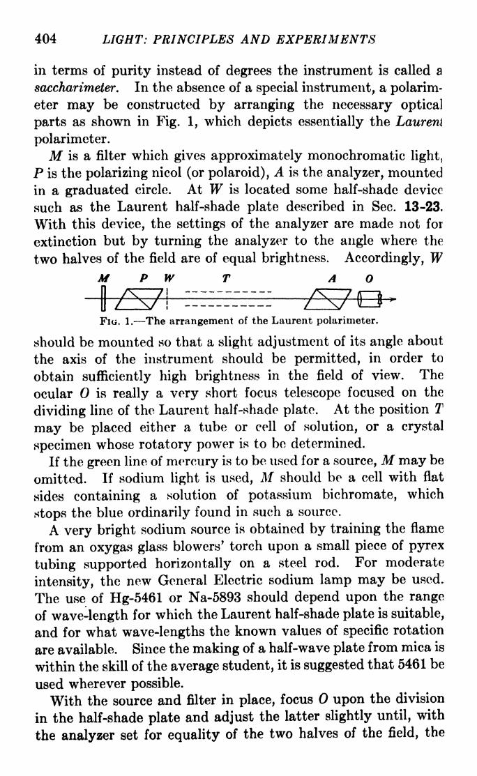
404 LIGHT: PRINCIPLES AND EXPERIMENTS
in terms of purity instead of degrees the instrument is called a
saccharimeter. In the absence of a special instrument, a polarim-
eter may be constructed by arranging the necessary optical
parts as shown in Fig. 1, which depicts essentially the Laurent
polarimeter.
M is a filter which gives approximately monochromatic light,
P is the polarizing nicol (or polaroid), A is the analyzer, mounted
in a graduated circle. At W is located some half-shade device
such as the Laurent half-shade plate described in Sec. 13-23.
With this device, the settings of the analyzer are made not for
extinction but by turning the analyzer to the angle where the
two halves of the field are of equal brightness. Accordingly, WM P W T A
FIG. 1. The arrangement of the Laurent polarimeter.
should be mounted so that a slight adjustment of its angle about
the axis of the instrument should be permitted, in order to
obtain sufficiently high brightness in the field of view. The
ocular is really a very short focus telescope focused on the
dividing line of the Laurent half-shade plate. At the position T
may be placed either a tube or cell of solution, or a crystal
specimen whose rotatory power is to bo determined.
If the green line of mercury is to be used for a source, M may be
omitted. If sodium light is used, M should be a cell with flat
sides containing a solution of potassium bichromate, which
stops the blue ordinarily found in such a source.
A very bright sodium source is obtained by training the flame
from an oxygas glass blowers' torch upon a small piece of pyrex
tubing supported horizontally on a steel rod. For moderate
intensity, the new General Electric sodium lamp may be used.
The use of Hg-5461 or Na-5893 should depend upon the range
of wave-length for which the Laurent half-shade plate is suitable,
and for what wave-lengths the known values of specific rotation
are available. Since the making of a half-wave plate from mica is
within the skill of the average student, it is suggested that 5461 be
used wherever possible.
With the source and filter in place, focus upon the division
in the half-shade plate and adjust the latter slightly until, with
the analyzer set for equality of the two halves of the field, the
EXP. 191 ROTATORY POLARIZATION 405
greatest brightness is obtained. At least five settings of the
analyzer for equality should be recorded, and the average taken.
The analyzer should then be rotated through 180 deg. and the
process repeated. These two settings 180 deg. apart are the zero
settings of the polarimeter. Then the various specimens to be
tested may be inserted at T and the analyzer rotated until
equality of the two halves is once more attained. Each deter-
mination of this position should be made at least five times, and
the average recorded, repeating after rotation through 180 deg.
It should be remembered that the insertion of a medium at T
changes the optical path and throws out of its focus upon the
dividing line of W, so that refocusing is necessary.
Sometimes the angle of rotation is so large that it is not
immediately known whether the rotation of the plane of vibration
is clockwise or counterclockwise. A second observation may be
made with a shorter length of substance or, in the case of solu-
tion, with smaller concentration, to determine this point. Or,
the rotation may be observed with both the 5461 line of mercuryand the 4356 line. The rotation of the plane is usually smaller
for the red than for the blue.
Part A. The Optical Rotation of Quartz. The rotation is
proportional to the thickness of quartz traversed (in the direc-
tion of the optic axis), and depends upon the wave-length and
slightly upon the temperature. If the angle of rotation p for the
green mercury line is known, that for sodium light may be
found from the equation
<P(6893)=
V>(5461) X 0.85085. (1)
The temperature effect is given by
Vt = *>o(l + 0.0001440 between 4 and 50C.
The value of ^(54i) at 20C. for a plate 1 mm. thick cut perpen-
dicular to the optic axis is 25.3571 deg. of arc.
It should be kept in mind that quartz occurs both right-handed
and left-handed. The specimen used should be examined with
white light between crossed nicols to make sure that it is not cut
from a twinned crystal.
Part B. The Rotatory Power of Pure Cane Sugar. In this
case the so-called direct method may be used, which supposes
that the sample of sugar contains no impurities which are also
optically active.

406 LIGHT: PRINCIPLES AND EXPERIMENTS
With a good analytical balance weigh out 26 gm. of pure cane
sugar (rock candy), which has been previously pulverized anddried in a desiccator for about 24 hr., or over sulphuric acid
in vacuo. Mix this thoroughly with distilled water, allowingnone of the sugar to be lost, in a graduate to make exactly
100 c.c. The most scrupulous cleanliness and exactness in
measurement should be observed. Keep the solution covered
to avoid loss by evaporation.
Fill a tube 20 cm. long with the sugar solution, having first
determined exactly what the length of the column of liquid will
be. Record the mean of several determinations of equality in
the two halves of the field. Repeat after rotating the analyzer
through 180 deg. The specific rotation is given by
where X is the wave-length used, a is the observed rotation in
degrees of arc, I the length of the solution in decimeters, and c
the concentration in grams per 100 c.c. of solution. The value
[~\20C.
a'
for cane sugar (sucrose, C^H^On) is 66.45 dee.J5893
of arc. Since it is a little difficult to make observation at
exactly 20C., a correction of 0.02 deg. of arc may be subtracted
from the experimentally determined value for each degree centi-
grade above 20C.The rotation ratio for sucrose, analogous to that given in
eq. 1 for quartz, is
? ( U9J)=
*> ( M6i) X 0.84922. (3)
Part C (Optional). The purity of a commercial sample of
cane sugar may be tested by the method outlined in Part B.
The sample should be prepared in the same manner as in Part B,
except that the solution should be a little stronger than 26 gm.
to each 100 c.c. of water, until it is certain that there will be
no turbidity. If the solution is slightly turbid, it may be
clarified as follows: Make a saturated solution of alum in
water. Pour into about two thirds of it a slight excess of
ammonium hydroxide and then pour in enough of the remaining
one third to get a slightly acid reaction. Add to the sugar
solution only a drop at a time. Too much will, because of the

EXP. 20J VERIFICATION OF BREWSTER'S LAW 407
change in concentration, introduce an error which cannot be
neglected. The remaining water should now be put in to bringthe concentration to specifications.
Substituting the value of a obtained for this sample into eq. 2,
calculate the value of c, and the percentage of purity.
Part D (Optional). The methods described above make no
provision for the errors possible due to the presence of optically
active impurities. For this purpose, the invert method is used.
Take 100 c.c. of the solution prepared in Part C, and add drop
by drop 10 c.c. of concentrated hydrochloric acid, specific gravity1.2 (38.8 per cent solution), shaking meanwhile. Since the reac-
tion is delayed, set this aside for not less than 24 hr. and keep the
temperature at 20C. or over. Dilute the invert solution to 200
c.c. Measure the rotation as before, and multiply it by 2,
because of the reduced concentration. Calculate c as directed
in Part C.
The result obtained in this manner will be more accurate than
by the direct method, provided the invert solution is properly
made.
Part E (Optional). Measure the rotations of several optically
active substances.
EXPERIMENT 20
VERIFICATION OF BREWSTER'S LAWFrom Fresnel's laws of reflection, in Sees. 13-13 and 14, which
should be read carefully before this experiment is begun, it
follows that for transparent isotropic media tan ip=
n, an
equation known as Brewster's law. The angle ip is that for
which i + T = 90 deg. This affords an experimental method of
determining n, the principal difficulty being that it is required
to find the angle of a Nicol prism, or other analyzer, at which
extinction of a polarized beam occurs.
It is also possible to measure the change, upon reflection, of
the direction of vibration of a plane-polarized beam. This
change is given by eq. 13-18:
cos (i r)tan a jr. (
= tan /?,cos (i H- r)
where a is the angle between the direction of vibration of the
incident light and the plane of incidence and the angle between

4Q8 LIGHT. PRINCIPLES AND EXPERIMENTS
the direction of vibration of the reflected light and the same
plane. If both i and r are known, the values of ft for several
values of a may be calculated. It is a simple matter to measure i
and a, but the measurement of r is difficult. If n is knownbeforehand from some other experiment, r may be calculated
from Snell's law. For this reason it is convenient to use in the
experiment a prism or glass block for which the value of n has
been quite accurately determined.
Apparatus. A spectrometer equipped with graduated circles
which may be clamped on the telescope and collimator tubes, a
100
30 40 50 60. 70
Angle of Incidence, i
Fio. 1.
80 90
pair of nicols to go in the circles, a Gauss eyepiece, sources of
white and monochromatic light, and a prism or block of glass
whose index is known. Polaroids may be used instead of nicols,
but they should be mounted in good optical glass.
Part A. This consists of a trial determination of n from
Brewstcr's law. Adjust the collimator and telescope for parallel
light, and clamp over the telescope lens one of the graduated
circles containing a nicol. Open the slit wide. The circle and
nicol should be previously examined so that the setting corre-
sponding to the plane of vibration of the transmitted light is
known, or a Wollaston prism may be employed as described
in Experiment 17. Use a monochromatic source of as high

EXP. 20] VERIFICATION OF BREWSTER'S LAW 409
intensity as possible and one for which n is known. On the
spectrometer table set the glass prism or block so that the light
from the collimator is reflected from one face. It is importantthat the face be absolutely clean. The riicol should be set so that
its plane of transmission is parallel to the plane of incidence, i.e.,
in a horizontal plane. This will insure maximum intensity at
the beginning of the experiment. Rotate the spectrometertable slowly and the telescope twice as fast, so as to keep the
light in view at all times. Somewhere in the neighborhood of an
angle of incidence of 57 deg., depending on the glass used, it
should be possible to extinguish the light by turning the nicol.
Reference to Fig. 1 shows that this point of extinction is difficult
to determine accurately, because the curve of reflection is not
symmetrical about the point where 7 = 0. By means of the
Gauss eyepiece find the normal to the glass surface. Substitute
the value of ip in Brewster's law and compare the calculated and
known values of n.
Part B. Fit the second nicol into a graduated circle and clampit over the collimator lens. Orient the nicol so that its plane of
transmission makes an angle other than or 90 deg. with the
plane of incidence. Use monochromatic light for which n is
known. With the analyzer measure for several values of i
on either side of the angle of complete polarization determined
in Part A. The angle i should be at intervals of between 2 and
5 deg. To find each 0, the analyzer should be set for extinction
several times and a mean value recorded. Do not forget to
record the position of the normal at each setting i. (To render
this unnecessary, it is possible to use a very convenient table, so
geared that it turns half as fast as the telescope. Ordinarily
this is called a minimum deviation table. With this equipment,
i need only be measured once.) Make a table of data, with i in
the first column, calculated in the second, and measured /3 in
the third. There should, of course, be a change in the sign of
at the angle of complete polarization. Plot the measured
angles of against the corresponding values of i. The point
where the curve crosses the i-axis gives ip . From this, n maybe calculated.
How does the value of n obtained compare with that from
Part A? with that from other experiments? What are the chief
sources of error in this experiment?

410 LIGHT: PRINCIPLES AND EXPERIMENTS
EXPERIMENT 21
THE OPTICAL CONSTANTS OF METALS
The theory of metallic reflection is discussed briefly in Sees.
15-10 and 11. For a more extended discussion the student
should consult Drude, "Theory of Optics," and Wood, "Physical
Optics." The principal experimental facts may be summarized
as follows:
a. Metals do not completely polarize light at any angle of reflection.
6. Plane-polarized light incident upon a metallic surface is uponreflection changed to elliptically polarized light, unless the plane of
vibration is either parallel or perpendicular to the plane of incidence.
c. The ellipticity is due to a phase difference A introduced, on reflec-
tion, between the components of the vibration parallel and perpendicular
to the plane of incidence. The ellipticity is greatest for the angle of
incidence <p for which this phase difference A =ir/2. This angle is
called the angle of principal incidence $.
d. Circularly polarized light incident at the angle <p is reflected as
plane-polarized light with its plane of vibration making an angle ^ with
the plane of incidence. The angle $ is called the angle of principal
azimuth.
As stated in the text, theoretical relationships can be obtained
between these angles and the quantities n, the index of refraction
of the substance, and K, the absorption index. These are given
in one form with a high degree of approximation in eqs. 15-15,
for any value of A. In order to make these equations applicable
to the experimental conditions described above, A is put equal
to IT/2, whereupon eqs. 15-15 become
K = tan 2#,
w2(l + *2
)= sin 2 cos 2
.
As will be seen from (c) and (d} above, there are two experi-
mental methods of determining n and K. Incident plane-polar-
ized light may be reflected from the surface at the angle <p, and
the value of # determined for which it becomes circularly polar-
ized upon reflection. Or, incident circularly polarized light maybe reflected as plane-polarized and the azimuth # determined
for which it is completely extinguished by an analyzer.
Since difference of phase is responsible for the change of polar-
ization, the experiment should be performed, not with white, but
monochromatic light.

EXP. 21] THE OPTICAL CONSTANTS OF AfETALS 411
With n and * known, the value of the reflectivity R may be
calculated by means of eq. 15-10.
Apparatus. The spectrometer, polarizer, and analyzer usedin Experiments 17 and 20, or, the polarizer, analyzer, and Babinet
compensator used in Experiment 18. A mercury arc and filter
for X5461. Several plane glass surfaces freshly coated with
metals. It is recommended that heavy opaque aluminum,silver, and copper be deposited by evaporation on plane glass
surfaces about 2.5 cm. square. If evaporation is not possible,
polished plane surfaces may be used, although in the polishing
process the surface often takes on foreign matter which changesits character.
Part A. n and K with the Babinet Compensator. Set the
wedges of the compensator so that the central dark fringe is dis-
placed through a distance which corresponds to a phase differ-
ence of one quarter of a complete period. Set the analyzer for
maximum blackness of the fringe. Then allow plane-polarized
light to fall on one of the coated plates, which should be held
securely at the middle of the spectrometer table. Change the
angle of incidence by rotating the table, and the telescope twice
as fast, until the central dark fringe comes back to the central
position. Record this angle of incidence, which is <p. Thenturn the analyzer until the central fringe is once more black.
This will give the angle #.
Part B. Alternative Method with Quarter-wave Plate. With
a X/4 plate change the plane-polarized light transmitted by the
polarizer to circularly polarized light. Let this be incident uponthe metallic surface, and find the angle of incidence (<p) for which
the reflected light is plane-polarized, as determined by the
analyzer. Record also the azimuth of the analyzer, i.e., the
angle its plane of transmission makes with the plane of incidence.
Substitute the values of <p and # found by either of these
methods in eqs. 1 to get n and K.
From eq. 15-10, calculate R, the reflectivity. The following
values of n and K are taken from the International Critical Tables,
Vol. V, page 248. They are for opaque surfaces. Semitrans-
parent surfaces yield different values. The values of the optical
constants of metals vary widely among observers, principally
because of the difficulty of obtaining an uncontaminated
surface.

412 LIGHT: PRINCIPLES AND EXPERIMENTS
EXPERIMENT 22
POLARIZATION OF SCATTERED LIGHT
Read Sees. 15-12 and 13 on the scattering of light and its
polarization.
Apparatus. A spherical liter flask, a 500-watt projection
amp, a cylindrical shield of metal with a slot in one side aboutI cm. wide. A Nicol prism or polaroid in a graduated circle.
k little hyposulphite of soda and some concentrated sulphuricicid.
Clean the flask and put in it about a quarter of a teaspoonful)f hyposulphite of soda. Half fill the flask with distilled water
ind shake it to dissolve the hyposulphite of soda and also to
5et rid of the bubbles which gather on the sides. In a graduatenix about 0.5 c.c. of concentrated sulphuric acid with 100 c.c.
>f distilled water, and wait till it clears. Set the lamp in a
vertical position, base down, put the shield around it, and set
.he flask so that the broad wedge of light through the slot falls
m the hyposulphite of soda solution.
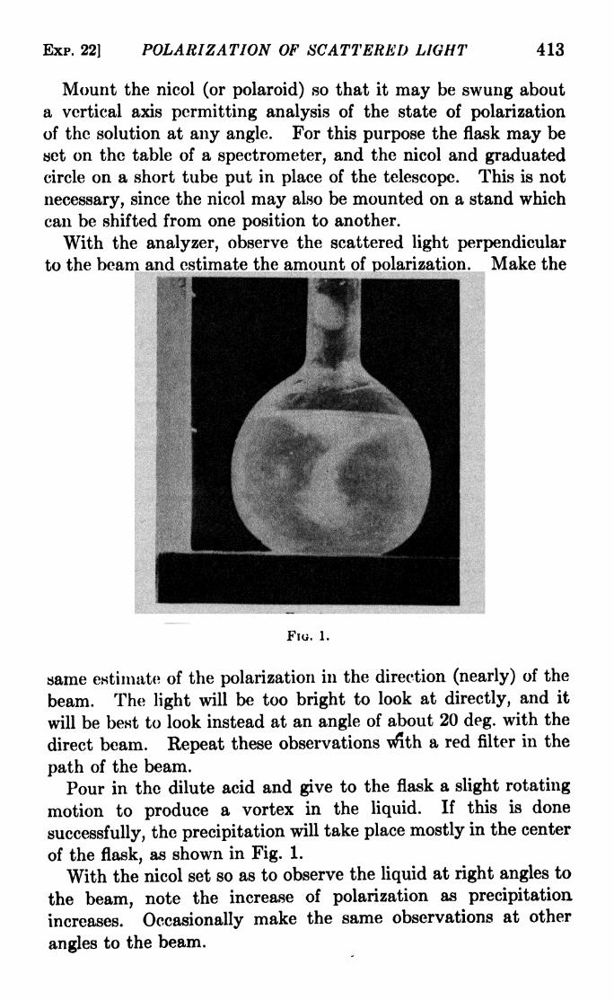
EXP. 22) POLARIZATION OF SCATTERED LIGHT 413
Mount the nicol (or polaroid) so that it may be swung about
a vertical axis permitting analysis of the state of polarization
of the solution at any angle. For this purpose the flask may be
set on the table of a spectrometer, and the nicol and graduatedcircle on a short tube put in place of the telescope. This is not
necessary, since the nicol may also be mounted on a stand which
can be shifted from one position to another.
With the analyzer, observe the scattered light perpendicular
to the beam and estimate the amount of polarization. Make the
FIG. 1.
same estimate of the polarization in the direction (nearly) of the
beam. The light will be too bright to look at directly, and it
will be best to look instead at an angle of about 20 deg. with the
direct beam. Repeat these observations with a red filter in the
path of the beam.
Pour in the dilute acid and give to the flask a slight rotating
motion to produce a vortex in the liquid. If this is done
successfully, the precipitation will take place mostly in the center
of the flask, as shown in Fig. 1.
With the nicol set so as to observe the liquid at right angles to
the beam, note the increase of polarization as precipitation
increases. Occasionally make the same observations at other
angles to the beam.

414 LIGHT: PRINCIPLED AND EXPERIMENTS
Write a description of what you have observed, noting espe-
cially the degree of polarization before and after the acid was
poured in the flask, the growth in polarization, the direction of
vibration of the scattered light, the color effects, and any other
effects you have seen.
EXPERIMENT 23
THE FARADAY EFFECT
For the theory of this experiment, read Sec. 16-6.
Apparatus. In order to produce the rotation of the plane of
vibration of a light beam traversing a medium in a magnetic
field, it is necessary to have a coil of considerable field strength.
While such coils are not ordinarily part of the equipment of a
light laboratory, they actually cost far less than many pieces of
optical equipment and may be used for a variety of purposes, in
laboratory instruction, lecture demonstration, and research. Acoil with a hollow cylindrical center, having a field strength of
about 1,000 gauss, will produce a measurable Faraday -effect
in a column of carbon bisulphide 15 cm long. The field at the
center of a single solenoid of length L and radius jR, due to current
7 through n turns per centimeter, is given by
H = 4irnl .
J-;.=) (gauss)+ R 2
and for many layers of turns, there will be a value of.// for each
layer. For successful operation over any but very short periods
of time, the coil should be water-cooled. There are different
systems of water cooling, a common one being the insertion every5 or 10 cm. along the coil of a hollow disk through which water
flows at a good rate. Unless the laboratory is equipped for
the construction of a properly insulated and water-cooled coil, it is
wiser to purchase one of sufficient strength, exactly as telescopes,
spectrometers, microscopes, and other accessories are purchased.
The remaining items of apparatus consist of a polarizer and
analyzer, a graduated circle for the latter, a half-shade plate, a
mercury arc and filter, or a sodium source. The use of sodium
is not recommended as more precise determinations are possible
with Hg-5461. Tubes for containing liquids may be similar
to those used for the sugar experiment, Experiment 19, Part B.
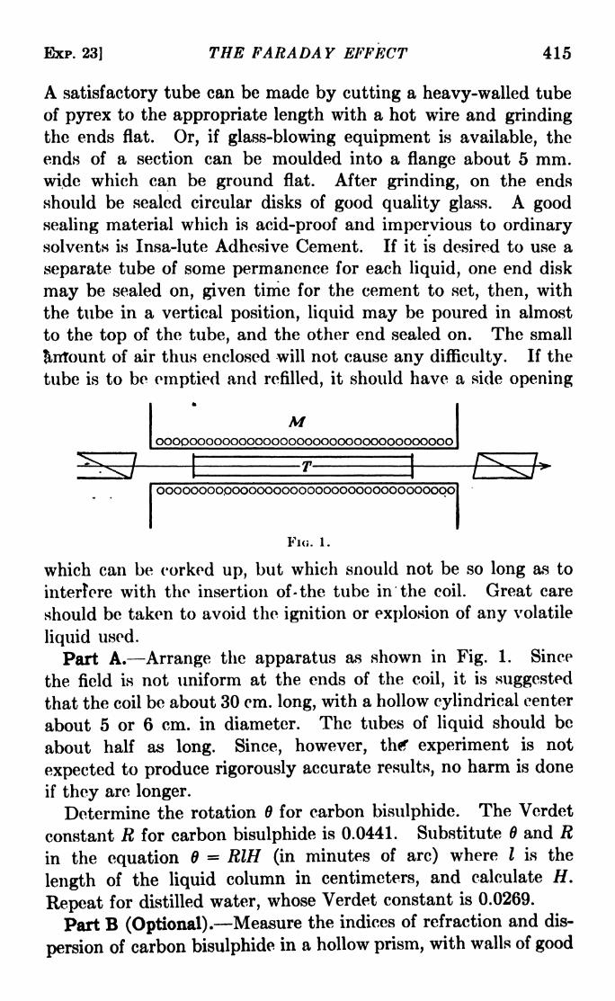
BXP. 23] THE FARADAY EFFECT 415
A satisfactory tube can be made by cutting a heavy-walled tube
of pyrex to the appropriate length with a hot wire and grinding
the ends flat. Or, if glass-blowing equipment is available, the
ends of a section can be moulded into a flange about 5 mm.wide which can be ground flat. After grinding, on the ends
should be sealed circular disks of good quality glass. A good
sealing material which is acid-proof arid impervious to ordinarysolvents is Insa-lute Adhesive Cement. If it is desired to use a
separate tube of some permanence for each liquid, one end disk
may be sealed on, given time for the cement to set, then, with
the tube in a vertical position, liquid may be poured in almost
to the top of the tube, and the other end sealed on. The small
fintount of air thus enclosed will not cause any difficulty. If the
tube is to be emptied and refilled, it should have a side opening*
Mooopoooooooooooooooooooooooooooooooo
oooooooo.ooooooooooooooooooooooooocx>ol
Fio. 1.
which can be corked up, but which snould not be so long as to
interfere with the insertion of-the tube in the coil. Great care
should be taken to avoid the ignition or explosion of any volatile
liquid used.
Part A. Arrange the apparatus as shown in Fig. 1. Since
the field is not uniform at the ends of the coil, it is suggested
that the coil be about 30 cm. long, with a hollow cylindrical center
about 5 or 6 cm. in diameter. The tubes of liquid should be
about half as long. Since, however, thf experiment is not
expected to produce rigorously accurate results, no harm is done
if they are longer.
Determine the rotation for carbon bisulphide. The Verdet
constant R for carbon bisulphide is 0.0441. Substitute 6 and Rin the equation - RIH (in minutes of arc) where / is the
length of the liquid column in centimeters, and calculate H.
Repeat for distilled water, whose Verdet constant is 0.0269.
Part B (Optional). Measure the indices of refraction and dis-
persion of carbon bisulphide in a hollow prism, with walls of good

416 LIGHT: PRINCIPLES AND EXPERIMENTS
optical glass free from strains, over the range from about 4300 to
6000 angstroms by the method of Experiment 5. Find the
value of dn/d\ for X4356 and X5461 of mercury, and for the
sodium lines. Find the angle of rotation 6, and substitute
0, X, dn/d\, e, m, and c in the equation
e
and thus calculate H.
In each case a good filter is desirable, as the color effects due to
dispersion of rotation are pronounced.Part C (Optional). If facilities permit, an exceedingly inter-
esting experiment is to measure the rotation due to a semi-
transparent iron film in a magnetic field. With the evaporatingoutfit (Appendix V) deposit a thin film of iron on one half of a
circular disk of good optical glass about 1 in. in diameter, andfree from strains. A coat which transmits between one half
to one fourth of the light is satisfactory. Fasten this in a
support which will hold it in a position normal to the field and
place it at the middle of the coil. Measure the rotation produced
by the glass alone and that by the iron coating and the glass,
subtract the first from the second, to obtain the rotation due to
the iron film. Since the angle will be very small, the experimentshould be regarded only as qualitative, and a^ a demonstration
of the rotatory power of iron. A field of 5000 gauss or over
will be required for this experiment.

APPENDICES


APPENDIX I
A COLLINEAR RELATION USEFUL IN GEOMETRICALOPTICS
For an ideal optical system, a point-to-point, line-to-line, and
plane-to-plane correspondence between object and image maybe expressed in terms of coordinate geometry by the equations
=
y =
I
ax 4- by
4-
-\- cz
4-
_
d
ax 4- by + cz -\-d
4" b sy -\- c*z 4- ds
-f by 4- cz 4- d\'
(D
in which x, y, and z represent the coordinates of an object pointand x', y
f
,and z
f
the coordinates of the conjugate image point.
We may conventionally prescribe that the object space be
placed on the left, with positive directions to the right and up,while the image space be on the right with positive directions to
the left and up.This general relationship can be limited for ideal symmetrical
coaxial optical systems. A symmetrical optical system is one
in which each reflecting or refracting surface is generated by
rotating an element of the surface about the optic axis. In such a
system, for any plane of incidence containing the optic axis, the
magnification in, and position of, the image plane will alwaysbe the same for a given object plane. Hence we need consider
only the xy- and x'y'-planes, the optic axes being in the x- and
^'-directions. Equations 1 may accordingly be simplified to
x' = a\x
ax4-
4- by
+4- d
4- dz
ax 4- by + d
(2)
A second property of symmetrical optical systems is that a
change in the size alone of the object causes no change in the
419

420 LIGHT: PRINCIPLES AND EXPERIMENTS
position of the image, but only a conjugate change of size. Thismeans that a change in the value of y in eqs. 2 must cause no
change in x', but only in y'. As the equations stand, this is not
true, but it can be made true by putting 6, 61, 02, and rf2 each equalto zero, reducing the equations to
ami *--,. (3)-,ax 4- d ax -f d
These may be solved for x and y, obtaining
di dx' , yf
(adi aid)x = -,, an(i y = v l '
ax a\
Now the coefficients a, d, a\, di, and b2 are values for a particular
optical system depending on the radii of curvature of the surfaces,
their distance apart, and the indices of refraction of the media.
Furthermore, the linear equation ax -f- d = obviously repre-
sents the principal focal plane in the object space, since it places
x' at infinity. Likewise the equation ax' ai = represents
the principal focal plane in the image space. By the substitu-
tions x = xi -- and x' = x\ H -> the origins are shifted toa a
the principal focal points. The resulting equations are
ad i aid
(4)
XiXi =
y
y ax i
We may further simplify eqs. 4 by putting
i- aid _ ff
,, 62
a*" ' a
where / and /' are constants depending upon the radii of curva-
ture of the surfaces, their distances apart, and the indices of
refraction of the media, so that finally, dropping the subscripts,
xx' =//', and y- = f- = y- (5)
y x j
Equations 5 hold for any ideal optical system in which the fore-
going limitations placed on the general collinear relation exist.

APP. TIJ CORRECTION FOR SPHERICAL ABERRATION 421
APPENDIX II
THIRD-ORDER CORRECTION FOR SPHERICALABERRATION FOR A THIN LENS IN AIR
From Fig. 2-1,
n' _ sin <p _ a -f- r\ b'
n sin <?' b a' TI^ '
But by the cosine law,
62 = (a + r,)* + r,2 -
2(a + rOn cos a (2)
and
6' =(a' ri)
2 + ^i2-f 2(a' ri)ri cos a. (3)
a 2 a 4 a 6
By expansion, cos a = 1o7 + T]~ A! "^~
' ' ' Neglecting
higher powers of a than the second, and substituting for a its
approximate value
and
6 = a (5)
Using the binomial theorem
{x ~T~ y)~ x ~t~ tix y ~i~
for n 2, considering the right-hand member of eq. 4 to be
CL I t*i h^
2xy, y = --^ and, to a sufficient degree of approximation,
ri 2
considering h to be small.
and, similarly,
-<['--?)}Substituting eqs. 6 and 7 in eq. 1,

422 LIGHT: PRINCIPLES AND EXPERIMENTS
in which HZ and n\ have been substituted for n' and n, and the
subscript m is used to indicate the image distance with a single
surface. This substitution is made in order to facilitate the
application of the results to the case of a lens in air, in which
case n\ n$ = 1 and nz= n.
Since in view of the approximation already made h is small
with respect to the other dimensions, we can substitute for a'
wherever it occurs in the coefficient of /i2 the value derived from
the first-order equation,
n\ nz _ HZ n\
a a' r\
whence
Hl n '2 n*~ ni
a am'
4. _i_ 4-, .
For the second surface of the lens, the distance to the virtual
object from the vertex is am', hence the equation analogousto eq. 8 for this surface is
_ n - j_ _^ n 3~ ni
' '~
/i2/
where a^ is the distance from the lens to the focus for the rays
intersecting the lens at a distance h from the axis. Since h is
small, we can substitute for amf wherever it occurs in the coeffi-
cient of A 2 the value of am'
derived from
am'
a' r z
whence for the second surface,
__^ Va'n2/\

Apr. II] CORRECTION FOR SPHERICAL ABERRATION 423
For the case of a lens in air, n\ = n 3= 1 and n2
= n. Substitut-
ing these values in eqs. 9 and 11,
1 n _n-\ h*(n- 1V 1 1\V + 1 1\
a+ 57
~~TT~ + 2\~^~An +
/ \~^~ +n/
l\(
1 _ iVA 4- 1 _ J_\/\^ a'/ \
'r2/
and
_ JL + J_ = l - n.
h*(n
am' ak
'r 2
+2\ n 2
(13)
The sum of eqs. 12 and 13 is
n - 1 W\(l iV/n + 1,A
n2'
2L\r,^
a) \ a"*"
n/
For paraxial rays,
1.
lf ^( l l\ /i-x- H ,
= (n 1)1---
) (lo)a a' '\ri r2/v '
Hence,
I _ J_ = _!L~J. ^a' ak
'~
n 2"
2'
where K is the quantity in the large brackets in eq. 14. The
difference between the focal lengths for paraxial rays and those
intersecting a lens a distance h from the axis may be written
/ / ^ n I h~K,
,
ak' - a' = -a'
-^---=- (lb)
11 &
provided the difference between ak' and a' is small enough so
that for their product may be substituted a' .

424 LIGHT: PRINCIPLES AND EXPERIMENTS
APPENDIX III
DERIVATION OF EQUATIONS FOR ASTIGMATICFOCAL DISTANCES AT A SINGLE REFRACTING
SURFACE
In Fig. 1 let be an object point, not on the axis, in the plane
containing the line element AP of a single spherical refracting
surface and C, its center of curvature. Then if coma is absent,
all the rays which have the same inclination u as OP with OCwill intersect the line OC extended in a point such as 1%. Let
Fio. 1.
OP =s, and PIz = s2 . Then, from the law of sines, in triangle
OP/28 82 0/2
sin u' sin u sin (<p <?')'
in triangle OPCr= = OC
.
sin a sin u sin v5'
and in triangle PC/ 2
r ,S'2 C/2
(1)
(2)
sin u sn a sn
From eq. 2,
from eq. 3,
sin u
_ r sin <p'
2sin u'
(3)
(4)
(5)

APP. Ill] EQUATIONS FOR ASTIGMATIC DISTANCES 425
Adding eqs. 4 and 5,
PC + C7. - 07. - - + (6)sin w sm w v '
Substituting this value of 0/2 in eq. 1 and using the first and last
members of eq. 1,
s
sn w sn [shijp
sin <p'
sin u sin t*'(7)
From the first and second members of eq. 1, sin u (s2 sin u')/s,
whence eq. 7 becomes
s
sn u sn
I'" -" '1
(<p </)LS2 sin u' sin u' \
Expanding sin (<p <?') and substituting for sin <p its value from
Snell's law, i.e.,
sin <p= sin ^', (9)
eq. 8 may be written
n n _ n cos<f>
n cos <p , .
s s z r
This gives the distance s2 ,measured from the surface, of the
sagittal or secondary focus.
Consider next two rays, OP and another adjacent ray OA.
Since they are refracted by the surface at different distances
from the intersection of OC with the surface they will, after
refraction, intersect at a point I\ not on OC extended. Let the
angle between OA and OC be u + du, that between AI\ and
P/i be du', and let PI\ s\. Since fron>the figure
<p a + w, and <?'= a u',
by differentiation it follows that
d<p= da + rfw, and d<p
f = c/a' dw'. (11)
Considering the angles du, du', and da to be equal to their sines,
it follows from the law of sines that
, PA cos <p t ,PA cos <?' , PA M0v
du = -----t du - ----- > da = - j (12)'

426 LIGHT: PRINCIPLES AND EXPERIMENTS
whence, in eq. 11,
/II-
\r
T) ^ i
cos j j / r>^= P.4I - H---, and d< = PA
s
Differentiation of SnelPs law in eq. 9 gives
n eos <p d^ = n' cos <p
f
d<p', (14)
and on substituting the values of dy and dp' from eq. 13 this
becomes
1 COS <
cosr s
, ,[1 COS <p'l= n cos <p >
L r si J
which may be written
n cos 2<p n' cos- \p _ n' cos </?' n cos
This gives the distance lf measured from the surface, of the
tangential or primary focus.
APPENDIX IV
ADJUSTMENT OF A SPECTROMETER
Spectrometers vary widely in their adaptability to a variety
of uses, precision and ease of adjustment, and consequently in
cost. For most of the experiments in this book a moderately
expensive instrument will serve as well as the most costly to
demonstrate the principles of optics. The precision to be
desired is perhaps greatest in the case of the experiments on the
index of refraction of a prism and the dispersion of prisms and
gratings. There are certain minimum requirements to be met
by any instrument. The optical parts should be of good quality,
the mechanical construction should be rigid and sufficiently
massive to prevent flexure, and the graduated circle should permitan accuracy of setting at least to 5 sec. of arc.
The essential parts of a spectrometer are: A circle graduatedin degrees of arc, equipped either with verniers or micrometer
microscopes with which angles may be read; a rotatable table
on which prisms or other optical parts may be set; a collimator
and slit; and a telescope. The ideal arrangement is to have each
one of these four parts independently rotatable on a cone or axis,
but arranged so that the table, the collimator, and the telescope
APP. IV] ADJUSTMENT OF A SPECTROMETER 427
may either be clamped to the mounting or to the graduatedcircle. Sometimes the verniers (or microscopes) are fixed to
the arm of the telescope so that they rotate with it, while the
table, the collimator, or both, may be clamped to the graduatedcircle. In any case, the user of the spectrometer should studythe demands made by any particular experiment before proceed-
ing with its performance.When in adjustment, the telescope and collimator tubes should
be set so that no matter what their angle about a vertical axis
may be, their axes are always perpendicular to, and intersect, the
main vertical axis of the spectrometer. A satisfactory instru-
ment will be equipped with devices to make this possible. More-
over, when in adjustment, the slit of the collimator should be
at the principal focus of the collimator lens, and the telescopecross hairs should be at the principal focus of the telescope
objective.
1. Adjustment of the Telescope for Parallel Light. Method1. Remove the telescope from the spectrometer and point it
at a bright object, such as a lamp globe or the sky. With the
eye previously accommodated to distant vision, slide the eyepiece
in or out in the draw tube, keeping the position of the cross
hairs fixed until the cross hairs appear sharp. This will insure
that the experimenter makes observations with a minimum of
eyestrain. It is well, perhaps, as a final adjustment, to pull
the eyepiece out to the point beyond which the cross hairs
appear to become slightly blurred. Next point the telescope
through an open window at some object a few hundred feet
away, and rack the cross hair and eyepiece together in or out
until a distinct image is seen. Try this several times. Makesure that the eyepiece has a sufficiently snug fit in the drawtube
so that it will not slip too freely and destroy this adjustment.
Method 2. This involves the use of a Gauss eyepiece, without
which several experiments cannot be performed. It is described
in detail in Sec. 7-3 and is illustrated in Fig. 7-4. Its relation
to the spectrometer is illustrated in Fig. 1. Light from a source
will thus be reflected past the cross hairs through objective O.
If it is then reflected from a plane surface M, such as the face of a
mirror or prism, directly back into the collimator, an image of
the cross hairs will appear. Provided the cross hairs are at the
principal focus of 0, this image will be in the same plane. When

428 LIGHT: PRINCIPLES AND EXPERIMENTS
the cross hairs and their image are both in sharp focus, with no
parallactic displacement, the telescope is in correct adjustmentfor parallel light.
2. Adjustment of the Collimator for Parallel Light. Thecollimator and the telescope should next be set so that their
axes are coincident and intersect the vertical axis of the spectrom-eter. This may first be done roughly by sighting along the
tubes. A finer adjustment may be made by the use of a block
set on the prism table with a vertical edge at the center of the
table, sighting past it with -the slit and eyepiece removed, with-
out disturbing the position of the cross hairs. Replace the
Cross-
hairs
II
Fia. 1. Sketch of a telescope equipped with a Gauss eyepiece
eyepiece and slit, taking care to bring the former once more into
correct focus on the cross hairs. Open the slit to a convenient
width, say a millimeter or less. Rack the slit in or out until a
sharp image of it is at the plane of the cross hairs without paral-
lactic displacement. The collimator will then be adjusted for
parallel light.
2a. Alternative Method of Focussing a Spectrometer. Schus-
ter's Method. If neither a distinct object nor a Gauss eyepiece
is available, the following method, due to Schuster, may be
employed.Use the mercury arc with filter for 5461 angstroms, or a sodium
source. Adjust the telescope and collimator in a straight line
across the center point of the spectrometer table. Put the
prism so that it has maximum illumination from the collimator
and orient it to the position of minimum deviation (see Sec. 8-1).
Rotate the prism slightly to the other side of minimum deviation
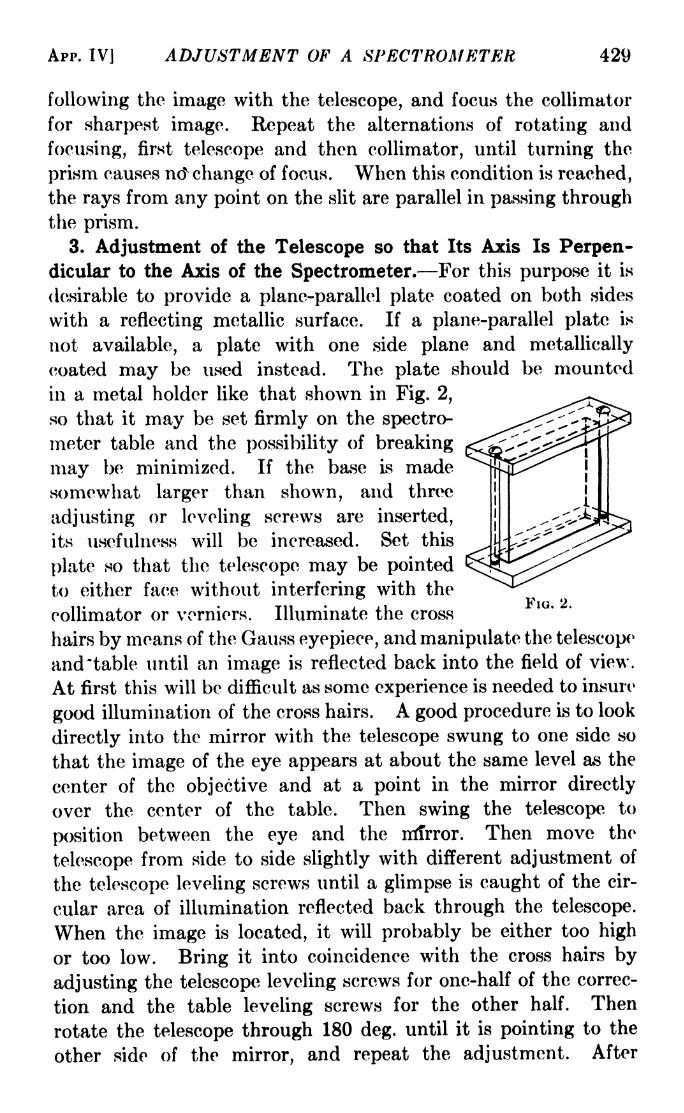
APP. IV] ADJUSTMENT OF A SPECTROMETER 429
following the image with the telescope, and focus the collimator
for sharpest image. Repeat the alternations of rotating and
focusing, first telescope and then collimator, until turning the
prism causes nd change of focus. When this condition is reached,
the rays from any point on the slit are parallel in passing throughthe prism.
3. Adjustment of the Telescope so that Its Axis Is Perpen-dicular to the Axis of the Spectrometer. For this purpose it is
desirable to provide a plane-parallel plate coated on both sides
with a reflecting metallic surface. If a plane-parallel plate is
not available, a plate with one side plane and metallically
coated may be used instead. The plate should be mounted
in a metal holder like that shown in Fig. 2,
so that it may be set firmly on the spectro-
meter table and the possibility of breaking
may be minimized. If the base is madesomewhat larger than shown, and three
adjusting or leveling screws are inserted,
its usefulness will be increased. Set this
plate so that the telescope may be pointed
to either face without interfering with the
collimator or verniers. Illuminate the cross
hairs by means of the Gauss eyepiece, and manipulate the telescope
and "table until an image is reflected back into the field of view.
At first this will be difficult as some experience is needed to insure
good illumination of the cross hairs. A good procedure is to look
directly into the mirror with the telescope swung to one side so
that the image of the eye appears at about the same level as the
center of the objective and at a point in the mirror directly
over the center of the table. Then swing the telescope to
position between the eye and the mirror. Then move the
telescope from side to side slightly with different adjustment of
the telescope leveling screws until a glimpse is caught of the cir-
cular area of illumination reflected back through the telescope.
When the image is located, it will probably be either too high
or too low. Bring it into coincidence with the cross hairs by
adjusting the telescope leveling screws for one-half of the correc-
tion and the table leveling screws for the other half. Then
rotate the telescope through 180 deg. until it is pointing to the
other side of the mirror, and repeat the adjustment. After
FIG. 2.
430 LIGHT: PRINCIPLES AND EXPERIMENTS
several corrections of position on either side, the image of the
cross hairs should coincide with the cross hairs themselves, no
matter on which side the telescope may be. It should be
noted that, although the mirror surface is in adjustment, the
table may not be, so that the substitution of a prism or grating
may necessitate some further leveling. The telescope, however,
should now be correctly set so that its axis is perpendicular to,
and intersects, the principal axis of the spectrometer.
In some cases the axis of rotation of the table is not coincident
with the axis of the instrument. The adjustment above is,
however, the most useful one. In case it is desired simply to
adjust the telescope perpendicular to the axis of the table, this
may be done by moving the mirror and table through 90 deg.
between adjustments with the Gauss eyepiece.
The collimator may now receive its final adjustment. Set the
telescope and collimator in a straight line pointing toward a
light source so that the slit, in a vertical position, coincides with
the intersection of the cross hairs. Place a hair, toothpick, or
fine wire across the slit and on a level with the center of the
collimator tube, and adjust the leveling screws of the latter
until the shadow of the obstacle coincides with the intersection
of the cross hairs. Sometimes the slit length and eyepiece
magnification are such that no obstacle is required, both ends
of the slit being in view at the same time.
An alternative method is to rotate the slit to a horizontal
position for leveling the collimator. This is not generally
recommended, since often there is no provision for free rotation
of the drawtube of the slit. Forced rotation of the slit may then
tend to destroy some defining pin in the tube, or wear the threads
of the connection between the drawtube and the slit so that the
latter may no longer be definable in a vertical position.
APPENDIX V
PREPARATION OF MIRROR SURFACES
1. Chemical Deposition of Silver. For this method the stu-
dent is referred to the "Handbook of Chemistry and Physics,"
published by the Chemical Rubber Publishing Co. The method
is tedious and uncertain and should not be used unless the more
satisfactory evaporation method cannot be used.

APP. VJ PREPARATION OF MIRROR SURFACES 431
2. Deposition by Evaporation. This is by far the most
satisfactory method, and can be used for the greatest variety
of substances. Since the essential parts of the apparatus are a
tungsten coil which can be raised electrically to a high tempera-
ture, an enclosure in which the pressure can be reduced to
approximately a cathode-ray vacuum,and a rack for supporting the plate to
be coated, quite simple apparatus can
be utilized. The writer has obtained
good surfaces, for use in a small inter-
ferometer, by making use of a liter
flask into which was sealed temporarily
a glass plug carrying the leads to the
heating coil, the vacuum being obtained
with an oil pump and a trap of outgassed
charcoal. However, such devices areFT?
only temporary, and the laboratory in L-
which much optical work is to be done
should be provided with a more perma-nent equipment, such as is illustrated in
Fig. 1.
A base plate of steel is mounted
firmly on a stand, table, or rigid shelf.
The base plate should be thick enoughto withstand the force of atmospheric
pressure on its lower surface, with a FlG i Evaporating appa-
wide margin of safety. For a bell jar ratus. B, base plate; WW,_. ,. , ,, ! , , i i i_ water-cooled electrodes; T,
of 6 in. diameter the plate should be u^d air or CO2 trap. D
cold-rolled steel % in. thick, and thicker diffusion pump; F, to fore
. ,. mi i_ J.L i i pump; P, plate to be coated;
for larger jars. Ihrough the plate are ^ shield .
R> glass rod for
drilled a hole about 1 in. in diameter moving shield; s, sylphon; E,_ .. j , ,1 testing electrode; C, heatingfor evacuation and two or more holes coiL
about 3 in. apart for the terminals.
While two terminals are sufficient for most purposes, three permit
the use of two heating coils which may be used for different
metals. The terminals should be water-cooled so as to prevent
overheating, a suggested design being shown in Fig. 2. Ordinary
automobile spark plugs screwed into the base plate from above
have been used in place of water-cooled terminals, but they are
short-lived.
jrr . . ;Ar -* ^ I

432 LIGHT: PRINCIPLES AND EXPERIMENTS
The bell jar should be of good quality and ground with emeryon the base plate. The neck should preferably be of the type
which can be fitted with a stopper. On this is fastened with some
suitable cement such as deKhotinsky, sealing wax, shellac, or
glyptal, a disk of brass with a rod extending through it, to act as a
terminal for a high-voltage discharge from a spark coil. The base
plate may serve as the other terminal. This discharge is useful
for testing the vacuum.
A very useful device, not absolutely
necessary, is a sylphon about 2 in. long
soldered to the lower side of the disk.
This is then firmly sealed to the top of the
jar. The rod which acts as the high-
tension terminal is made quite long, and
equipped on its lower end with a glass
extension. The rod may then be flexed
so as to explore, with the glass end, a
considerable area inside the bell jar. The
writer has used this device for steering a
glass shield in and out between the heat-
ing coil and the surface to be coated.
Instead of a bell jar, a large cylinder
of metal is sometimes used, with a heavy
glass plate sealed on top. This plate may also be of metal, in
which case one or more windows about 2 in. in diameter should
be put in.
A stand S (Fig. 1) of convenient size is used inside the bell
jar. On this may be mounted the mirror to be coated, suspended
face down on a thin sheet of metal cut to size and shape.
The diffusion pump, preferably a three-stage type with a
cooling trap T built into its upper end, as shown in Fig. 1,
should be equipped at its upper end with a %-in. flange to be
sealed on the lower side of the base plate. It is absolutely
essential that this pump be held rigidly. A convenient method is
to make the base plate the top of a table, the four legs being
ordinary water pipe about 1 in. in diameter. Large flanges
fitted to the tops of these pipes may then be screwed directly
to the base plate. The diffusion pump is then clamped in place
to the legs with large laboratory clamps, and sealed to the base
plate.
FIG. 2.
APP. V] PREPARATION OF MIRROR SURFACES 433
An ordinary Hyvac pump will serve as a fore pump. In case
a diffusion pump cannot be obtained, one or more charcoal
traps may be used to aid in the evacuation of the jar. This
process is, however, slow and tedious, especially since it is
sometimes necessary to make several trials for a desired coat.
The trap T in the top of the diffusion pump must be filled
with a cooling solution or liquid air, to prevent mercury vaporfrom rising into the bell jar and contaminating the metal deposit.
A satisfactory cooling solution is made by packing the trap with
dry ice and slowly pouring ordinary commercial acetone over it.
A small stopcock may be sealed to the upper part of the pumpjust below the flange to admit air to the jar.
The heating coil should be of tungsten for evaporating most
metals. For a few with low boiling points, such as antimony, it
may be of nickel. A suitable diameter for tungsten wire is
30 mils. It may be wound while red-hot into a helix to be
mounted horizontally. The winding can be done on a steel rod
about % in. in diameter or slightly larger. Some have a prefer-
ence for a cone-shaped helix to be mounted vertically, acting
as a sort of pot into which the metal is placed. The exact form
of the heating coil should be dictated by practical considerations
and experience, as its form is not important for ordinary mirror
coating.
There should be a large rheostat used in series with the heating
coil, to control the current, and fuses inserted in the circuit for
safety. The heating current may be 110 volts alternating
current.
After the coil is made and clamped in place, it should be
preheated in a high vacuum to get rid of the oxide on its surface.
The sylphon attachment mentioned above is useful in this
operation, as it eliminates opening the Hbell jar and pumping
down again after loading the coil with metal. Always after the
coil is heated, sufficient time should elapse for it to cool before
admitting air, so that oxidation is avoided.
Aluminum is by far the best metal for mirror surfaces. It
should be as pure as possible. Pure aluminum may be procured
in pellet form which can be conveniently spaded into the coil.
Some aluminum contains copper, which may be dissolved out
with nitric acid. Some workers use pure aluminum wire which
is fastened in small lengths to turns of the tungsten helix.

434 LIGHT: PRINCIPLES AND EXPERIMENTS
To render the apparatus airtight, the bell jar should be put in
place and moved slightly to grind out any particles of dust
which might adhere to its lower flange. Then, before pumpingis started, the edge should be sealed with plasticine. A special
plasticine in which apiezon oil is used is excellent, as the oil has a
very low vapor pressure. For most work, however, ordinary
plasticine will serve. Hot paraffine wax may also be
used.
The high-tension test coil for testing the vacuum may be an
ordinary )^-kva. transformer, with a rating of about 10,000 volts
across the secondary. A satisfactory vacuum for evaporation
is reached when no discharge is possible between the upper
terminal and the base plate. When this vacuum is attained,
turn on the heating current slowly, making sure the cooling
water is flowing through the terminals.
A suitable deposit is a matter of experience.
3. Deposition by Cathodic Sputtering. The same bell jar as
for evaporation may be used, except that to the electrode at the
top of the bell jar should be attached firmly a disk of the metal
to be sputtered. The disk should be slightly larger than the
metal to be sputtered. This disk is to be the cathode of a high-
tension discharge. A suitable source is the ^2-kva. transformer
mentioned in Sec. 2 above, but in this case the second terminal
in the apparatus must either be a small point shielded from the
mirror surface or it must be removed as far as possible from the
mirror surface. This may be accomplished by having a side
tube of about 1 in. diameter sealed to the tube connecting the
base plate and the diffusion pump, just below the flange. This
side tube should be about 6 in. long and have an aluminum
electrode sealed into the end of it.
Sputtering must be done with a higher pressure than evapora-
tion. This pressure may be calibrated roughly by the width
of the cathode dark space, which grows as the pressure drops.
A dark space of about 3 cm. indicates a satisfactory pressure.
The mirror to be coated should be mounted face up, below the
cathode, and just inside the cathode dark space.
Aluminum does not sputter well. Silver may be used suc-
cessfully, and is by far the best metal if this method of deposition
is to be used. The exact amount of deposit for a suitable mirror
is a matter of experience. Sputtering is found to be most
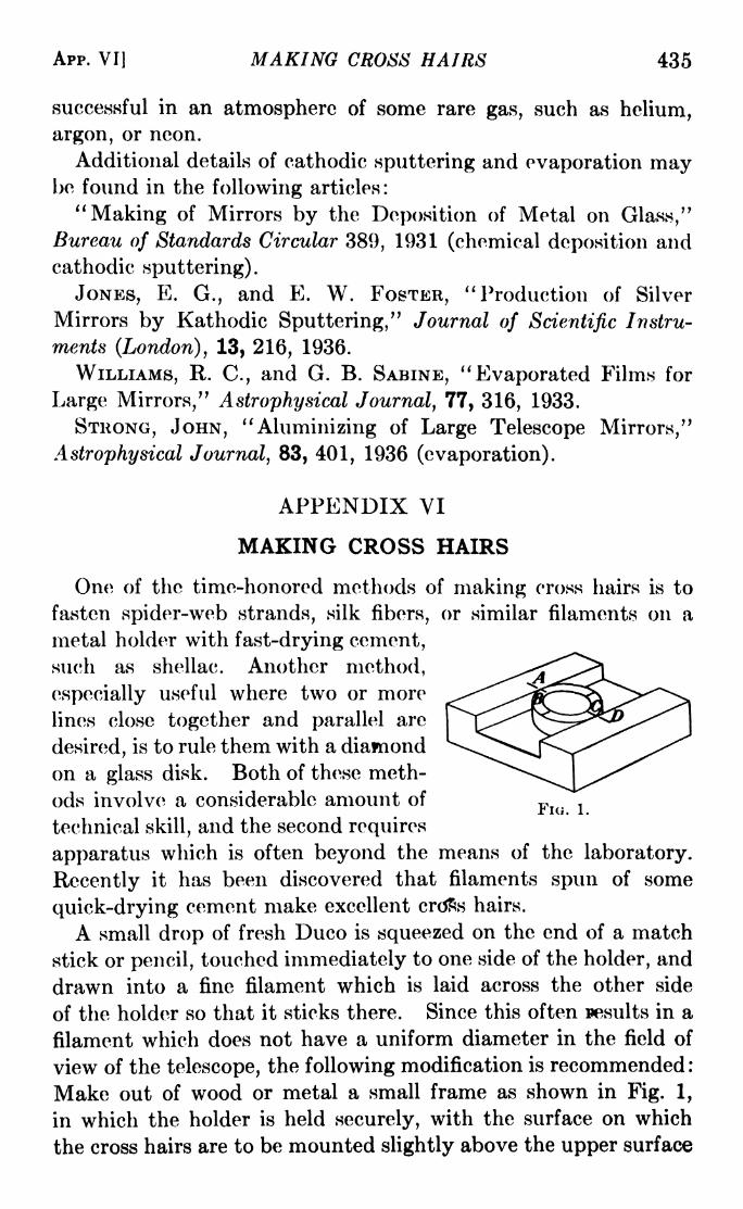
Apr. VI] MAKING CROSS HAIRS 435
successful in an atmosphere of some rare gas, such as helium,
argon, or neon.
Additional details of cathodic sputtering and evaporation maybe found in the following articles:
"Making of Mirrors by the Deposition of Metal on Glass,"Bureau of Standards Circular 389, 1931 (chemical deposition andcathodic sputtering).
JONES, E. G., and E. W. FOSTER, "Production of Silver
Mirrors by Kathodic Sputtering," Journal of Scientific Instru-
ments (London), 13, 216, 1936.
WILLIAMS, R. C., and G. B. SABINE, "Evaporated Films for
Large Mirrors," Astrophysical Journal, 77, 316, 1933.
STRONG, JOHN,"Aluminizing of Large Telescope Mirrors,"
Astrophysical Journal, 83, 401, 1936 (evaporation).
APPENDIX VI
MAKING CROSS HAIRS
One of the time-honored methods of making cross hairs is to
fasten spider-web strands, silk fibers, or similar filaments on a
metal holder with fast-drying cement,such as shellac. Another method,
especially useful where two or more
lines close together and parallel are
desired, is to rule them with a diamond
on a glass disk. Both of these meth-
ods involve a considerable amount of -,rio. 1.
technical skill, and the second requires
apparatus which is often beyond the means of the laboratory.
Recently it has been discovered that filaments spun of some
quick-drying cement make excellent crdss hairs.
A small drop of fresh Duco is squeezed on the end of a match
stick or pencil, touched immediately to one side of the holder, and
drawn into a fine filament which is laid across the other side
of the holder so that it sticks there. Since this often results in a
filament which does not have a uniform diameter in the field of
view of the telescope, the following modification is recommended:
Make out of wood or metal a small frame as shown in Fig. 1,
in which the holder is held securely, with the surface on which
the cross hairs are to be mounted slightly above the upper surface

436 LIGHT: PRINCIPLES AND EXPERIMENTS
of the frame. The fresh Duco is touched at A, drawn quickly
to a filament which is lowered to points B and C on the holder,
and fastened at D. Then a small drop of Duco is laid on the
filament at B and C to anchor it securely. The Duco must be
quite fresh or it will not spin properly. With a little practice,
extremely fine cross hairs can be made in this manner. It is
recommended that the entire operation be carried on under a
hand magnifier or equivalent lens mounted in position above
the frame.
APPENDIX VII
STANDARD SOURCES FOR COLORIMETRY 1
It is recommended that three illuminants A, B, and C as
described below, be adopted as standards for the general col-
orimetry of materials.
A. A gas-filled lamp operated at a color temperature of
2848K.B. The same lamp used in combination with a filter consisting
of a layer, 1 cm. thick of each of two solutions B\ and J52 ,con-
tained in a double cell made of colorless optical glass. The
solutions are to be made up as follows:
Solution B\:
Copper sulphate (CuSO 4.5H 2O) 2. 452 gramsMannite [C6H8(OH) fi]
2. 452 grams
Pyridine (C 5H 5N) 30.0 c.c.
Water (distilled) to make 1000.0 c.c.
Solution B 2 :
Cobalt ammonium sulphate
[CoSO 4.(NH 4 ) 2SO 4.6H 2O] 21 . 71 grams
Copper sulphate (CuSO 4.5H 2O) 16.11 grams
Sulphuric acid (sp. gr. 1.835) 10.0 c.c.
Water (distilled) to make 1000.0 c.c.
C. The same lamp used in combination with a filter consisting
of a layer, 1 cm. thick of each of two solutions C\ and C2 ,contained
in a double cell made of colorless optical glass. The solutions
are to be made up as follows :
1 Taken from T. SMITH and J. GUILD, "The C.I.E. Colorimetric Standards
and Their Use," Transactions of the Optical Society, London, 33, 73, 1931-1932.

APP. VII] STANDARD SOURCES FOR COLORIMETRY 437
Solution C\\
Copper sulphate (CuSO 4.5H 2O) 3. 412 gramsMannite [C6H8(OH) 6] 3. 412 gramsPyridine (CjH 6N) 30. c.c.
Water (distilled) to make 1000. c.c.
Solution C-i\
Cobalt ammonium sulphate
[CoSO 4.(NH 4 ) 2S0 4.6H 20] 30. 580 gramsCopper sulphate (CuSO 4.5H 2O) 22 . 520 gramsSulphuric acid (sp. gr. 1.835) 10.0 c.c.
Water (distilled) to make 1000. c.c.
It is also recommended that the following spectral-energydistribution values for each of these illuminants shall be used in
computation of colorimetric quantities from spectrophotometricmeasurements .
Source A. The spectral distribution of energy from this source
may be taken for all colorimetric purposes to be that of a black
body at a temperature of 2848K. The value assumed for
Planck's constant c$ is 14,350 micron-deg.
SPECTRAL DISTRIBUTION OF ENERGY; SOURCES B AND C

438 LIGHT: PRINCIPLES AND EXPERIMENTS
Sources B and C. The spectral distributions of energies
for these sources, as computed from the spectrophotometric
measurements of the transmission of the filters made by Messrs.
Davis and Gibson of the Bureau of Standards, are tabulated
on p. 437.
APPENDIX VIII
THE FRESNEL INTEGRALS
In Sec. 12-6 a vector-polygon method has been described bywhich the amplitude of the distribution due to any part of a
light wave may be evaluated. Whenthe separate elements of the disturb-
ance are taken small enough, the
vectors representing them become a
curve which for an unobstructed wavefront is the Cornu spiral (Fig. 12-9)
X of which a drawing to scale is included
in this appendix. Cornu originally
constructed this spiral by plotting
the values of Fresnel's integrals, which may be derived in the
following manner:
Consider such a curve (Fig. 1) representing the summa-tion of a number of elements of amplitude of a wave disturbance.
Let x and y be the coordinates of an element of disturbance dS.
Then the angle <j> between the z-axis and the tangent to the
curve is the phase of the element dS. We may write
,dx . dy
cos * -, mn 4-
= .
x =/ cos dS, y =
J sin <> dS. (1)
It is now necessary to evaluate <f> and dS in terms of an actual
wave front. For this purpose we may consider a cylindrical
wave front W originating at a line source L (Fig. 2), perpendicularto the paper. It is required to find the intensity at a pointon the screen. By the cosine law, and substituting for 9 its
approximate value s/a,
c* = (a + 6)2 -fa2 -
2a(a + 6) cos -,(Ji

APP. VIII] THE FRESNEL INTEGRALS 439
or
or
c2 = 6 2H s 2
, approximately,
a + 6
2a6
This is sufficiently accurate when 8 is small.
The difference of phase be-
tween the disturbance at due
to its pole and that due to dWis measured by (c &)/X, so
that, if the first is given by sin
2irt/T, the second is given by
sin 27r( ~FIG. 2.
D (3)
and the entire disturbance due to all the elements by
=Jsin
2
The integral is taken between limits appropriate to the particular
case.
The amplitude contributed to O by an element of the wave
front dW is proportional to its area, inversely proportional to
the distance c from dW, and depends also on the obliquity of the
wave front. If we neglect these considerations and assume
merely that the amplitude due to any element is proportional
to the length of the element, then we may identify dW in eq. 3
as dS in eqs. 1. Similarly the phase angle <f> may be related to
the path difference (c 6), for </>=
(c 6), so that by eq. 2A
(a + *>X2
Substituting v2 for (a + b)s2/a6X, we may now write the expres-
sion for the intensity / due to the wave front in terms of the x and
y coordinates given in eqs. 1:
;[(/<-?sin (̂4)

440 LIGHT: PRINCIPLES AND EXPERIMENTS
The integrals in eq. 4 are known as Fresnel'i* integrals. Theyhave been evaluated by Gilbert,
1 and appear in the followingtable.
TABLE OF FREBNEL'B INTEGRALS
From these values the Cornu spiral shown in Fig. 3 was plottedon a large scale and reduced photographically.The assumptions made in this derivation, that is small, and
that dW is proportional to the length of the element,are tanta-
mount to the assumption that the effective portion of the cylin-
drical wave front is really confined to a very small area about
the pole of any point O under consideration.
1 GILBERT, PHILIPPE, Acad6mie Royale de Belgique, 31, 1, 1863. Correc-
tions have been made to his values of the cosine term for v\ equal to 0.1
and 1.8.

\
<N
d'3
a
Ji**
O+(3
1
C9
<41
O
&
441


TABLES OF USEFUL DATATABLE I. USEFUL WAVE-LENGTHS
The wave-lengths listed are principally those of lines which may beobtained with discharge tubes of helium, hydrogen, neon, mercury; withthe mercury arc, or in the spectrum of the sun. Only the stronger lines
due to these sources are listed. There are a few, such as the cadmium lines,
which may be obtained with an ordinary mercury arc containing an aftialgamof mercury and the other metals desired. The values given are in angstroms(1 angstrom = 10~ 8
cm.).
In any particular source there may appear lines fainter than those listed,
or lines due to impurities. If the wave-lengths of such lines are measured,
they may usually be identified by consulting H. Kayser, "Tabelle der
Hauptlinien der Linienspektra aller Elemente," published by Julius Springer,or Twyman and Smith, "Wave-length Tables for Spectrum Analysis,"
published by Adam Hilger, Ltd. An extensive table of wave-lengths is also
included in the more recent editions of the "Handbook of Chemistry and
Physics," published by the Chemical Rubber Publishing Co.
Hydrogen6562.8 H4861 . 3 H/j
4340.5
4101 . 7
3970.1
3889.0
H7
HHf
4339.2
4347.5
4358? 3
4077.8
4046.84046.6
|
Fraunhofer Lines
Helium7065.2
6678.1
5875.6
5047.
5015.
4921 . 9
4713.1
4471.5
4437.5
4387.9
4143.8
4120.8
4026.2
3964.7
3888.6
Neon6929.5
6717.0
6678.3
6599.0
6532.9i If the solar spectrum is
seen owing to a blend of Fe
6500.5
6402 2
6383.0
6334.4
6304.86266.5
6217.3
6163.6
6143.1
6096.2
6074.3
6030.0
5975.5
5944.8
5881.9
5852.5
5820.2
5764.4
5400.6
5341.1
5330.8
Mercury
^6234.36123.5
6072.6
5790.
5769.60
5460.
4916.0
used, with small dispersion, a wide absorption line also will be
and Ca lines, with a mean wave-length of 4307.8 angstroms.
443
Miscellaneous
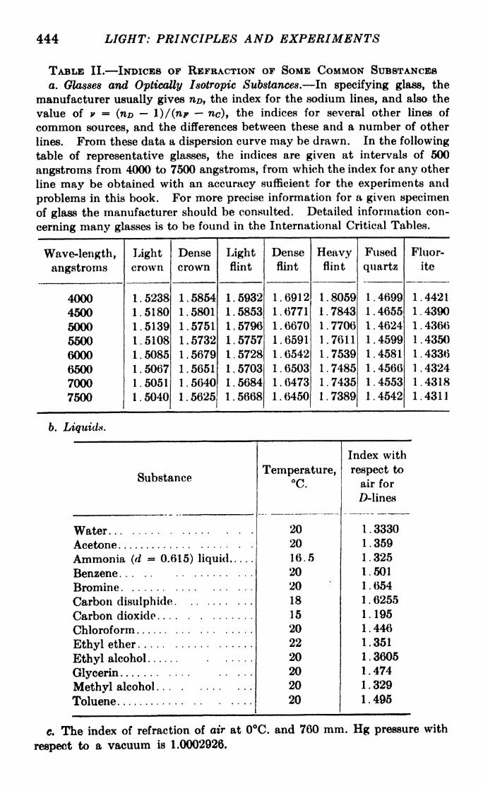
444 LIGHT: PRINCIPLES AND EXPERIMENTS
TABLE II. INDICES OF REFRACTION OF SOME COMMON SUBSTANCES
a. Glasses and Optically Isotropic Substances. In specifying glass, the
manufacturer usually gives n/>, the index for the sodium lines, and also the
value of v = (nD l)/(np nc), the indices for several other lines of
common sources, and the differences between these and a number of other
lines. From these data a dispersion curve may be drawn. In the following
table of representative glasses, the indices are given at intervals of 600
angstroms from 4000 to 7500 angstroms, from which the index for any other
line may be obtained with an accuracy sufficient for the experiments and
problems in this book. For more precise information for a given specimen
of glass the manufacturer should be consulted. Detailed information con-
cerning many glasses is to be found in the International Critical Tables.
b. Liquids.
c. The index of refraction of air at 0C. and 760 mm. Hg pressure with
respect to a vacuum is 1.0002926.

TABLES OF USEFUL DATA 445
d. Some Uniaxial Crystal*.
TABLE III. REFLECTING POWERS OF SOME METALSSince the measured reflecting power varies widely with the origin of the
surface and its age, these factors should be taken into account in using the
figures given below. The values given for silver, aluminum, and gold are
compiled from graphical data in an article on the evaporating process byJohn Strong in Astrophysical Journal, 83, 401, 1936, and are for freshly
evaporated opaque coatings. Experience shows that for the visible region
the reflecting power of silver diminishes between 15 and 20 per cent in two
or three weeks' time. The values for platinum, copper, steel, monel, and
speculum are for polished massive metals. In general these have less
reflecting power than the evaporated coats of the same metals. Additional
data may be found in the International Critical Tables,
* From other sources than those indicated above.

446 LIGHT: PRINCIPLES AND EXPERIMENTS
TABLE IV. FOUR-PLACE LOGARITHMIC TABLES

TABLES OF USEFUL DATA 447
TABLE IV. FOUR-PLACE LOGARITHMIC TABLES. (Continued]

448 LIGHT: PRINCIPLES AND EXPERIMENTS
TABLE V. TRIGONOMETRIC FUNCTIONS
Natural Cosines 45-90 c Mean Differences
(Subtract)

TABLES OF USEFUL DATA 449
TABLE V. TRIGONOMETRIC FUNCTIONS. (Continued)

450 LIGHT: PRINCIPLES.AND EXPERIMENTS
TABLE V. TRIGONOMETRIC FUNCTIONS. (Continued)

TABLES OF USEFUL DATA 451
TABLE V. - -TRIGONOMETRIC FUNCTIONS. (Continued)
Natural Tangents 45-90 Differences

452 LIGHT: PRINCIPLES AND EXPKRIMKNTX
TABLE VI. LOGARITHMS OK TRIGONOMETRY FUNCTIONS

TABLES OF USEFUL DATA 453
TABLE VI. LOGARITHMS OF TRIGONOMETRIC FUNCTIONS. (Continued)

454 LIGHT: PRINCIPLES AND EXPERIMENTS
TABLE VI. LOGARITHMS OF TRIGONOMETRIC FUNCTIONS. (Continued)

TABLES OF USEFUL DATA 455
TABLE VI. LOGARITHMS OF TRIGONOMETRIC FUNCTIONS. (Continued)


ANSWERS TO PROBLEMS
Answers are included only for those problems requiring a numerical solution
Chapter II, page 17
1. x 9 = -6.67; y'= -5.0. 2. x' = -8; y'
= +1.3. For a real image, 62.5 cm. away; for a virtual image, 37.5 cm. away.4. 72.25 cm. toward the mirror.
5. 5. 6. 60 cleg.
7. 1.5 cm. from surface; diameter = 1.20 mm.; a = 1.04.
8. n = 2.
9. 13.9 from the side; = +1.235; a = +1.15.10. About 54 ft.
12. 78.9 from the emergent nodal point.
Chapter III, page 29
2. / =/'
= +15; p = p' = 10; P and P' coincide at middle of sphere.3. / =
/'= +20; p = 0; p' = -6.67.
4. / = +15.9; /'- +21.2; A - -136; p = -<>
17 .
6. ft= +23.266; // = +31.095; /2
= + 132.85; // = +142.85;
/, = +85.712; /a'= +79.712; / = + 15.497; /'
= +20.712.
7. /2= -66.67 cm.
8. / = +20; at principal focal point F'\ 10 cm. outside of bowl.
9. If the index of glycerin is taken as 1.48, / = 1.04 mm.10. If only one side of the cylinder is used, and considering r\ = +500 cm.
and r 2= +498 cm., / = -373,500 cm. Considering r {
= r 2= +500
(.m.,/ = +750,000 cm.
Chapter IV, page 34
1. Less than 1 cm.
2. Exit pupil is 4.8 cm. toward eye from ocular and has a diameter of 1 cm.
3. HINT: find /3 for the entrance and exit pupils and use eq. 2-7. Image is
20.9 cm. to right of exit pupil and is 1.31 mm. in height.
4. If stop in front, //15; if behind, //1 3.5.
6.
Chapter V, page 44
1. One point 135 cm. from 20-candle-power lamp toward 30-candle-power
lamp; another point 133.5 cm. on side of 20-candle-power lamp.2. 1186.
3. Brightness = 5.83 X 10~ 4 candles per cm.2 = 1.83 X 10~3 lamberts.
457

458 LIGHT: PRINCIPLES AND EXPERIMENTS
Chapter VI, page 70
3. Distance of primary image from mirror vertex = 25.1 cm.; of secondary
image = 36.2 cm. Length of primary image = 3.06 cm.; length of
secondary image = 4.4 cm.; astigmatic difference = 11.1 cm.
6. 8.31 and 12.85 along axis from vertex.
6. fc = 50.0 179 cm., f = 50.000 cm., fP = 49.9645cm.,/,, = 50.0178cm.
Chapter VII, page 86
1. - 22.2. 4. ft=
8; / = 2.5.
2. 0.67 mm. 5. 1 in.
3. 4.16 cm. from glass. 7. /> = 7.79 cm.; 0* = 3.08.
Chapter VIII, page 99
2. Assuming minimum deviation in each case, dispersion at 4000 angstromsis 3.1 1 X 10s radians per cm., at 7000 angstroms is 5.66 X 10² radians percm. Sodium doublet just resolved if t 1.7 cm.
4. About 65 deg. 5. n = 1.18.
Chapter X, page 135
1. 5.86 X 10~5 cm. 4. 5461 angstroms.2. n = 1.00029. 5. 5.76 X i()" 4 cm.
3. About 14 17'.
Chapter XI, page 162
2. About 50 cm. 3. 0.0145 cm. 4. 5.945 mm.6. For R = 0.75, resolving power = 520,000; for R = 0.90, resolving
power = 1,475,000.
Chapter XII, page 206
1. 1 .22 X 10~3 cm.
2. For visual observations, about 51 sec. of arc or 3.5 mm. from center; for
photographic observations, a larger distance.
3. About 10,000 ft. 4. About 5.8 X 10~6 cm. 6. 6 = a.
6. R = 150,000 in first order; about 113 cm. on a side; 3.567 mrn.
Chapter XIII, page 249
1. t = 0.015 times an odd integer; parallel to the optic axis.
2. n = 1.58. 3. About 1 deg. 4. 0.0167T.
5. Slightly elliptical, direction of major axis parallel to original plane of
vibration.
6. 1.99.
Chapter XIV, page 271
1. 9875.02, 15239.22, 18473.69, 20572.95, 22012.21, all cm- 1.
2. vx = 27419.42 cm.' 1 -
)w - 3647 angstroms; V = 3.4 volts.

ANSWERS TO PROBLEMS 459
3. Total radiation per year = 1.42 X 1041ergs; of which 6.56 X 10" 1 strikes
the earth.
4. a, = 0.53 X I0-"cm.;t> = 2.182 X 108 cm. per sec.; W = 2.15 X 10~ 4
ergs.
6. Separations may be calculated from Rn/lti> = 8.9952/8.9976.6. T = 5786 deg. ahs.; E = 2.285 X 10 14
ergs.
Chapter XVI, page 322
1. About 15,000 gauss.
2. Yes, at 2150 angstroms in first order, 4300 angstroms in second order, etc.
4. About 20,000 gauss; R = 0.03.
Chapter XVII, page 339
1. Numerical aperture = 0.1503, assuming/' for eye is 2.07 cm2. About 30 cm. 3. Mngnification is about 3.33.

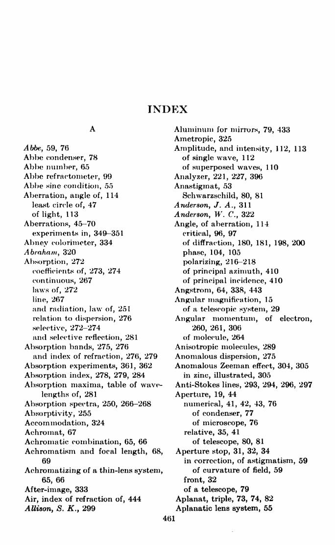
INDEX
Abbe, 59, 76
Abbe condenser, 78
Abbe number, 65
Abbe refractometer, 99
Abbe sine condition, 55
Aberration, angle of, 114
least circle of, 47
of light, 113
Aberrations, 45-70
experiments in, 349-351
Abney colorimeter, 334
Abraham, 320
Absorption, 272
coefficients of, 273, 274
continuous, 267laws of, 272
line, 267
arid radiation, law of, 251
relation to dispersion, 276
selective, 272-274and selective reflection, 281
Absorption bands, 275, 276
and index of refraction, 276, 279
Absorption experiments, 361, 362
Absorption index, 278, 279, 284
Absorption maxima, table of wave-
lengths of, 281
Absorption spectra, 250, 266-268
Absorptivity, 255
Accommodation, 324
Achromat, 67
Achromatic combination, 65, 66
Achromatism and focal length, 68,
69
Achromatizing of a thin-lens system,
65, 66
After-image, 333
Air, index of refraction of, 444
Allison, S. K., 299
Aluminum for mirrors, 79, 433
Ametropic, 325
Amplitude, and intensity, 112, 113
of single wave, 112
of superposed waves, 110
Analyzer, 221, 227, 396
Anastigmat, 53
Schwarzschild, 80, 81
Anderson, J. A., 311
Anderson, W. C., 322
Angle, of aberration, 114
critical, 96, 97
of diffraction, 180, 181, 198, 200
phase, 104, 105
polarizing, 216-218of principal azimuth, 410
of principal incidence, 410
Angstrom, 64, 338, 443
Angular magnification, 15
of a telescopic system, 29
Angular momentum, of electron,
260, 261, 306
of molecule, 264
Anisotropic molecules, 289
Anomalous dispersion, 275
Anomalous Zeeman effect, 304, 305in zinc, illustrated, 305
Anti-Stokes lines, 293, 294, 296, 297
Aperture, 19, 44
numerical, 41, 42, 43, 76
of condenser, 77
of microscope, 76
relative, 35, 41
of telescope, 80, 81
Aperture stop, 31, 32, 34
in correction, of astigmatism, 59
of curvature of field, 59
front, 32
of a telescope, 79
Aplanat, triple, 73, 74, 82
Aplanatic lens system, 55
461

462 LIGHT: PRINCIPLES AND EXPERIMENTS
Aplanatic points, 55-58
of microscope objective, 58
Aplanatic surface, 4
equation of, 4, 58
Aplanatic system, 40
Apochromatic system, 70
Arago, 169
Arkadiew, W ., 168
Astigmatic difference, 52, 53
measurement of, 350
Astigmatic focal planes for meniscus
lens, 60
Astigmatic focus, primary, 393
Astigmatic image positions, 51, 52
equations for, 52
derivation of, 424-426
illustrated, 53
Astigmatic spectral line, 393
Astigmatism, 50-53
correction of, 59
of the eye, 325
in paraholoidal reflectors, 80
Atom model, Bohr's, 260
Rutherford's, 259, 260
Atomic number, 252
Atomic spectra, 251-255, 260-264
illustrated, 253, 267
Avogadro number, 259, 269, 287, 289
Axes, of elliptically polarized light,
225
positions of, 232, 400, 403
ratio of, 403
optic, in biaxial crystals, 240-242
of single ray velocity, 241, 242
Axis, optic, in uniaxial crystals, 209
210, 242
optical, 6, 8, 11
B
Babcock, //. />., 304, 306
Babinet compensator, 226-232, 284,
318
Babinet-Jamin compensator, 227
in analysis of elliptically polarized
light, 401-403, 411
Background, effects of, 43
Balmer formula, 251, 252
Buhner lines in Stark effect, 309Balmer series, in helium, 252
in hydrogen, 251, 253, 254
convergence X of, 271
wave-lengths of, 443
Balij, E. C. C., 395
Band spectra, 264-268
diagrams of, 266
photographs of, 267
Bartholinus, 208
Beams, J. H'., 321
Becquerel, Jean, 313, 314
Beer's law, 273
Benoit, J. R., 151
Biaxial crystals, 215
double refraction in, 237
optic axes in, 240-242
principal indices of refraction of,
239
rays in, 240
wave surface in, 239, 240
Bills, A. G., 331
Binocular vision, 325
Biprism (see Fresnel biprism)
Birefringence, 319
Birefringence constants, 319, 320
Birge, It. T., 236
Black body, defined, 255
Blacks, absorbing, 275
Blind spot, 323, 324
Bohr, N., 101, 254, 255
Bohr formula, 261, 262
Bohr theory, of absorption and
emission of radiation, 266-268
of atomic spectra, 260-264
of molecular spectra, 264-268
in Raman effect, 295, 296
of Stark effect, 311
Boltzmann, 256
Boltzmann's constant, 259
Born, A/., 237, 282
Brace, D. B., 313
Brace-Lemon spectrophotomctcr,363-365
Brace prism, 363, 364
Brackett series, 254
Bradley, 113, 114
Bray, de, Gheury, 116
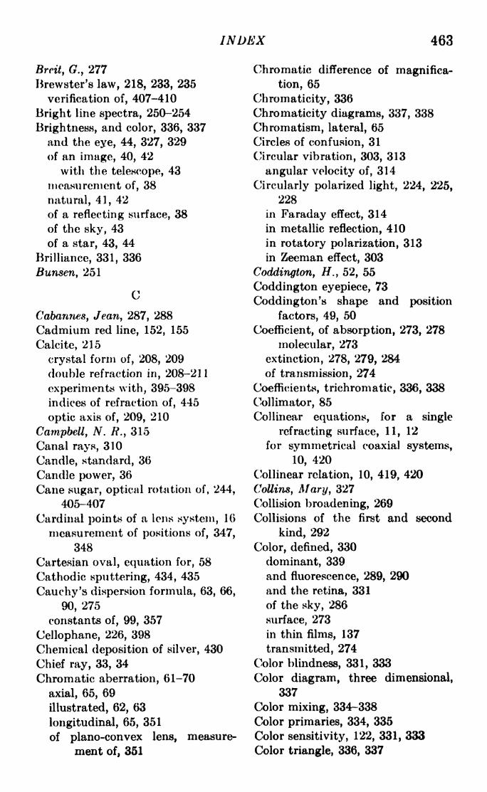
INDEX 463
Brcit, (?., 277
Brewster's law, 218, 233, 235
verification of, 407-410
Bright line spectra, 250-254
Brightness, and color, 336, 337
and the eye, 44, 327, 329
of an image, 40, 42
with the telescope, 43
measurement of, 38
natural, 41, 42
of a reflecting surface, 38
of the sky, 43
of a star, 43, 44
Brilliance, 331, 336
Bunsen, 251
C
Cabannes, Jean, 287, 288
Cadmium red line, 152, 155
Calcite, 215
crystal form of, 208, 209
double refraction in, 208-211
experiments with, 395-398
indices of refraction of, 445
optic axis of, 209, 210
Campbell, N. /?., 315
Canal rays, 310
Candle, standard, 36
Candle power, 36
Cane sugar, optical rotation of, 244,
405-407
Cardinal points of a lens system, 16
measurement of positions of, 347,
348
Cartesian oval, equation for, 58
Cathodic sputtering, 434, 435
Cauchy's dispersion formula, 63, 66,
90, 275
constants of, 99, 357
Cellophane, 226, 398
Chemical deposition of silver, 430
Chief ray, 33, 34
Chromatic aberration, 61-70
axial, 65, 69
illustrated, 62, 63
longitudinal, 65, 351
of plano-convex lens, measure-
ment of, 351
Chromatic difference of magnifica-
tion, 65
Chromaticity, 336
Chromaticity diagrams, 337, 338
Chromatism, lateral, 65
Circles of confusion, 31
Circular vibration, 303, 313
angular velocity of, 314
Circularly polarized light, 224, 225,
228
in Faraday effect, 314
in metallic reflection, 410
in rotatory polarization, 313
in Zeeman effect, 303
Coddington, H.y 52, 55
Coddington eyepiece, 73
Coddington's shape and position
factors, 49, 50
Coefficient, of absorption, 273, 278
molecular, 273
extinction, 278, 279, 284
of transmission, 274
Coefficients, trichromatic, 336, 338
Collimator, 85
Col linear equations, for a single
refracting surface, 11, 12
for symmetrical coaxial systems,
JO, 420
Collinear relation, 10, 419, 420
Collins, Mary, 327
Collision broadening, 269
Collisions of the first and second
kind, 292
Color, defined, 330
dominant, 339
and fluorescence, 289, 290
and the retina, 331
of the sky, 286
surface, 273
in thin films, 137
transmitted, 274
Color blindness, 331, 333
Color diagram, three dimensional,
337
Color mixing, 334-338
Color primaries, 334, 335
Color sensitivity, 122, 331, 333
Color triangle, 336, 337

464 LIGHT: PRINCIPLES AND EXPERIMENTS
Color value, 336
Color vision, 331
theories of, 332-334
Colorimeters, 334
Colorimetry, standard sources for,
436-438
Colors, complementary, 332, 333
primary, 334, 335
in thin films, 137
Coma, 53-55
elimination of, 55
illustrated, 54, 56
observation of, 350, 351
in paraboloidal reflectors, 80
Comatic circles, 53, 54
Combinations of two systems, 21
Compton, A. //., 294, 299
Condensers, 77
Abbe, 78
Cardioid, 78
Conductivity, electrical, and optical
properties, 282, 283, 284
Cones, 331, 333
Conical refraction, external and
internal, 241, 242
Conjugate points, 13, 14, 20
Conjugate rays, 13, 14
Continuous absorption and emis-
sion, 267, 268
Continuous spectra, 250
Contrast sensitivity, 327
Coordinates, in combination of two
systems, 21
in object and image spaces, 1 1,419
Cornea, 323, 325
Cornu double prism, 247
Cornu-Jellet prism, 248
Cornu polariscope, 222
Cornu spiral, 171-176, 438, 440
graph of, 441
Cotton-Mouton birefringence con-
stant, 319, 320
Cotton-Mouton effect, 319
Crew, H.9251
Critical angle of refraction, 96, 97
Cross-hairs, instructions for making,. 435, 436
Crystalline lens, 323, 324
Crystals, character of light trans-
mitted by, 225
classes of, 215
direction of vibration in, 218, 219
optic axes in, 209, 210, 240-242
principal section of, 210, 219
wave fronts in, 211
wave surfaces in, 237, 239
wave-velocity surfaces in, 211-215Curvature of field, 58
correction of, 59
experiment in, 351
Cyanine, color transmission of, 274
D
Dark-field illumination, 77
de Bray, Gheury, 116
Descartes laws of refraction, 212
Dichroism, 274
Dielectric constant, 276, 277
Diffraction, 164-206
by circular opening, 203-206
by rectangular opening, 202, 203
(See also Fraunhofer diffrac-
tion; Fresnel diffraction)
Diffraction grating, 194-199, 390-
395
adjustments of, 390, 391
concave, 393-395
dispersion of, 197, 198, 393, 394
mountings for, 393-395
resolving power of, 198, 199, 392,
393
transmission, 393
Diopter, 23
Dioptric system, 27
Dipole moment, 277, 289
Direct-vision prism system, 96
Direct-vision spectroscope, 95, 96
Dispersion, anomalous, 275
early theories of, 275, 276
electromagnetic theory of, 277-
279
of a grating, 197, 198, 393, 394
of a prism, in angstroms per
millimeter, 92
angular, 92

INDEX 465
Dispersion, of a prism, factors affect-
ing, 91
at minimum deviation, 92, 358
quantum theory of, 279, 280
of rotation, 244
Dispersion curve of a prism, deter-
mination of, 357
Dispersion formulas, 63, 275-278
Dispersive power, 64, 65, 69, 356
Distortion, 60
experiment in, 351
illustrated, 62
Doppier broadening of a spectrum
line, 269
Double refraction, in calcite, 208-
215
in an electric field, 316-319
in gases, 318, 319
general treatment of, 237-240
in liquids, 317, 318
in a magnetic field, 319
wave fronts in, 211-214
wave surfaces in, 239
Double slit interferometer, 387-390
(See also Fraunhofer diffrac-
tion;Fresnel diffraction;
Limit of resolution)
Doublet, symmetrical, 61
Drude, P., 55, 234, 236, 244, 277, 284
du Bois, #., 316
Du Bridge L., 236
E
e/m, 304, 306, 314
Eagle mounting, 395
Echelon, 199-202
dispersion of, 200
order of interference in, 200-202
reflection, 202
resolving power of, 201
Einstein, A., 101, 260, 298
Einstein's photoelectric equation,
299
Electric field, in Kerr effect, 317
in Stark effect, 310
Electric force, 233, 234
and the light vibration, 234
Electrical Kerr constant, 318for carbon bisulphide, 318
table of, 319
Electro-optical effect, 316
in gases, 318, 319
in liquids, 318, 319
relation to electric field, 317
Electron, angular momentum of,
260, 261 306
charge and mass of, 262
ratio of charge to mass, 304, 306,
314
Electron spin, 269, 307
Electronic bands, 266
Elliptically polarized light, 223
analysis of, 399-403
analytic treatment of, 224, 229-
232
in Kerr effect, 315, 316, 318
in metallic reflection, 284
position of axes, 232, 400, 403
ratio of axes, 403
Emissive power, 255
Emmetropic, 325
Energy, internal, 264, 265
rotational, 265
Energy distribution, in interference
patterns, 123, 124
in standard sources, table, 437
Energy distribution laws, 257-259,
331, 362
Energy-level diagrams, 262
for absorption and emission, 268
for anomalous Zeeman effect, 308
for hydrogen, 263
for normal Zeeman effect, 307
Energy levels, in fluorescence, 292
probability distribution in, 268
for Raman effect, 295, 296
splitting of, in magnetic field, 307,
308
Energy states, atomic, 262
molecular, 264
Entrance pupil, 32-34, 40
of telescope, 79
Evaporation method for coating
mirrors, 431-434

466 LIGHT: PRINCIPLES AND EXPERIMENTS
Exit pupil, 32, 33, 40, 42, 43
of telescope, 79
Extinction coefficient, 278, 279, 284
Extraordinary ray, 395, 397
in calcite, 211
defined, 209
direction of vibration of, in 'nicol,
221
indices of refraction of, 212, 445
Extreme path, law of, 3, 4
Eye, accommodation of, 324
color sensitivity of, 122, 331, 333
far and near points of, 324
optical defects of, 324, 325
optical system of, 323, 324
schematic, 323
sensitivity of, 327, 328
Eye lens, 83
Eyepiece, Coddington, 73
erecting, 84, 85
four-element, 84, 85
Gauss, 74, 353, 354, 366, 427, 429
Huygens, 69, 75, 82, 83
micrometer, 74, 75
Ramsden, 73, 74, 82-84
triple aplanat, 73, 74, 83
(See also Ocular)
F
f/ number, 35, 41
Fabry, C., 151
Fabry-Perot interferometer, 142,
153-162
fringe intensity distribution in,
156-158
fringe shape in, 161, 162
order of interference in, 154, 155
ratio of wave-lengths, determined
with, 382-384
resolving power of, 158-161
Far point of the eye, 324
Faraday, M., 300, 301, 312, 316
Faraday effect, 312
experiment in, 414-416
explanation of, 313
and Kerr effect, 316
magnitude of, 314
in solutions, 314
Format's principle, 3-5
Field lens, 83
Fine structure of spectrum lines,
151, 152, 202, 269, 312
Fizeau, 114-116
Flicker photometer, 328
Flicker sensitivity, 327, 328
Fluorescence, of atoms, 292
in gases, 291, 292
polarization of, 290
and Raman effect, 297
Focal distances, astigmatic; deriva-
tion of equations for, 424-426
Focal length, of combination of
two thin lenses, 23
equivalent, 7
of thin lens system, 6, 20
from power formula, 25, 26
Focal length measurement, 343
by autocollimation, 344
of divergent lens, 345
Focal lengths, of components of an
achromat, 66
principal, of a system, 14
Focal points in combinations, 21
Focus, meridional, 51
primary, 51, 393, 426
sagittal, 51
secondary, 51
tangential, 51, 426
Foster, E. W., 435
Foster, J. S., 310, 311
Foucault, 114-116
Fovea, 323, 324, 331
Fowler, A., 253
Frank, N. H., 277
Fraunhofer, 251
Fraunhofer diffraction, 176, 385
defined, 164
in the echelon, 199-202
illustrated, 179, 196, 203, 206
by single slit, 178, 180-184
by two slits, 179, 184-186, 387-
390
Fraunhofer lines, 64, 356
table of, 64, 443
Fred, M., 267
Fresnel, 111, 165, 169, 237

INDEX 467
Fresnel biprism, 126, 129-132
interference fringes with, 131
in wave-length determination,
368-370
wave-length equation for, 130, 132
Fresnel diffraction, 176
denned, 164
illustrated, 168, 171, 177
by single slit, 175
by straight edge, 169-171, 174
by two slits, 176, 177
Fresnel equations, 233-235, 282
for absorbing media, 283
Fresnel integrals, 438-441
table of, 440
Fresnel mirrors, 126-128
interference fringes with, 128
in wave-length determination, 370
wave-length equation for, 127
Fresnel rhomb, 236, 237
Fresnel zones, 165, 166, 287
Fresnel's theory of rotatory polariza-
tion, 244-247
G
Gaertner Scientific Company, 95, 395
Gate, H. G., 267, 270
Gardner, I. C., 97
Gauss eyepiece, 74, 353, 354, 366,
427, 429
Gaussian image point, 46, 47
Geometrical optics, postulates of, 1
Ghosts, Rowland, 253, 391
Lyman, 391
Gilbert, P., 440
Glan polarizing prisms, 359, 363
Glan spectrophotometcr, 358, 359
Grating (see Diffraction grating)
Grating mountings, 393-395
Group velocity, 117-119
Guild, J., 436
H
h, 259, 262, 299, 311
Hagen, E., 284
Hale, G. E., 301
Half-shade plates and prisms, 248,404
Half-wave plate, 223, 226, 397Half-width of a spectrum line, 269
Hardy, A. <?., 70, 332, 336, 338
Harrison, G. R., 267
Hefner lamp, 36
Heisenberg, W ., 280, 295
Helmholtz, 276, 277, 327, 332
Helrnholtz-Ketteler dispersion for-
mula, 276
Hering's theory, 333
Houstoun, R. A., 112, 277, 302
Hue, 330
Hufford, M. E., 168
Huygens, 208, 219
Huygeiis construction in double
refraction, 211-213
Huygens ocular, 69, 75, 82, 83
Huygens principle, 110-112, 165, 166
Huygens wavelets, 111, 210, 211
Hydrogen, Stark effect in, 309
visibility curve for Ha of, 152
Hydrogen series, 253, 254
wave-lengths of, 443
Hyperfine structure, 270
Hyperopia, 325
Hyposulphite of soda, light scatter-
ing by, 285, 412, 413
Iceland spar (sec Calcite)
llluminant, standard, 336, 338, 436-
438
Illumination, of an image, 39-41
of a surface, measurement of, 37
Illuminators, dark field, 77
vertical, 77
Index of absorption, 278, 279, 284
measurement of, 411
Index of refraction, of carbon bisul-
phide, 119
complex, for absorbing media, 278,
283
defined, 2
determined, by minimum devia-
tion, 89

468 LIGHT: PRINCIPLES AND EXPERIMENTS
Index of refraction, determined, by
refractometer, 133-135
by total reflection, 97, 98
in double refraction, 212
in eletromagnetic theory, 277,
278
measurement of, by Babinet com-
pensator, 411
for divergent lens, 345
of glass block, 352
of glass plate, 367, 368
of glass prism, 365, 366
of liquids, 352, 353, 367
by Michelson interferometer,
376-380
by microscope, 352, 353
by spherometer, 345
by total reflection, 365-368
for metals, 284
Indices of refraction, in Faraday
effect, 314
numerical values of, 444, 445
principal, 239
Intensity comparisons, 37, 359
of bright lines 362
of continuous spectra, 360, 301
Intensity distribution, in continuous
spectra, 257-259, 360
in diffraction patterns, 170, 171,
176, 178, 183, 185, 195,205
in Fabry-Perot interferometer
fringes, 156-158
in interference patterns, 123, 124
Interference, compared with diffrac-
tion, 120, 176
conditions for, 120-123
division of amplitude, 124, 125,
137-162
in Newton's rings, 137-141
in thin films, 137
(See also Fabry-Perot inter-
ferometer; Michelson inter-
ferometer)
division of wave front, 124, 125
diffraction in, 176
Fresnel biprism, 126, 129-132
in Fresnel mirrors, 126-128
Interference, division of wave front,
in Rayleigh refractometer,
126, 132
(See also Echelon)with double and multiple beams,
142
general methods for production
of, 124, 125
order of, 154, 155, 198, 199
Interference fringes, in diffraction
patterns, 176-179, 185
forms of, 146, 147, 161, 162
illustrated, 128, 131, 138, 141,
149, 150, 155, 177, 179
intensity distribution in, 156-158
visibility of, 147-152, 158, 177,
179, 187
defined, 148, 157
Interferometer, double slit, 387-390
Fabry-Perot, 142, 153-162
Michelson, 142-152, 370-382
stellar, 153, 187-194
loriization, 267
Irradiation, 44, 326
Isotope effect, 270, 312
Isotropic medium, 2
refraction in, 212
Ives, H. E., 334
Ives colorimeter, 334
Jamin, 217
Jeans, Sir J., 258
Jena Glass Works, 59, 70, 362
Jones, E. G., 435
K
Karolus, A., 321
Katoptric system, 27
Kayser, 77., 443
Kepler, 250
Kerr, 315, 316
Kerr cell, 318
in measurement, of time intervals,
320, 321
of velocity of light, 321, 322

INDEX 469
Kerr constant, electrical, 318
magnetic, 316
Kerr effect, electro-optical, 316-319
magneto-optical, 315
KeMeler, 276
Kirchhoff, 251, 255
KirchhofPs laws of absorption, emis-
sion, and radiation, 255
Korff, S. A., 277
Kramers, IL A., 280, 294, 295
Krishnan, K. N., 293
Kundt, 314
L
Ladd-Franklin theory, 333
LaGrange's law, 14, 55
Lambert, the, defined, 38
Lambert's cosine law, 38, 39
Lambert's law of absorption, 273
Langsdorf, A., Jr., 236
Larmor, /., 315
Lateral magnification, 43, 54
defined, 11
of a telescopic system, 28
Lateral spherical aberration, 48, 50
Laurent half-shade plate, 248, 404
Laurent polar imeter, 404
Lawrence, E. O., 321
Least time, principle of, 3
Lemoine, J., 320
Lens (see Thin lens)
Lens combination, zero power, 81
Lens combinations, 21-29, 65-67
Lens formula, general; derivation
of, 23-26
Light, theories of, 100-102
Light flux, unit of, 36
Limit of resolution, of one and two
slits, 186, 187
Rayleigh's criterion of, 186
(See also Resolving power)
Line spectra, absorption, 260
emission, 250-254
Littrow mounting, 247
Lockyer, Sir N., 251
Longitudinal chromatic aberration,
63, 351
Longitudinal magnification, 15
of a telescopic system, 28
longitudinal spherical aberration, 48
measurement of, 349, 350
Lorentz, H. A., 277, 301, 302
Lo Surdo, 309-31 1
Lumen, defined, 36
Luminous intensities, comparison of,
37
Luminous intensity, of an image, 41
of a source, 36
Lummer, O., 258
Lyinan, T., 253
Lyman ghosts, 391
Lyrnan series, 253
M
MeDonald observatory telescope, 80
Magnetic field, angle of rotation of
plane of vibration produced by,
313, 416
effect of, on energy levels, 307, 308
on light source, 300
strength of, in Faraday effect, 416
in Zeeman effect, 302, 304, 308
Magnetic force, 234
Magnetic Kerr constant, 316
Magneto-optical effect, 315, 316
Magnification, angular, 15, 22, 29
chromatic difference of, 65
of compound microscope, 75
lateral, 11, 28, 54
longitudinal, 15, 28
normal, 43
of simple microscope, 72
Magnifier, compound, 72, 73
simple, 72
(See also Eyepiece; Ocular)
Magnifying power, 29, 78
Mains, 215
cosine-square law of, 220
law of, 5
Mann, C. R., 146
Martin, A. E., 141
Mass, reduced, 262
Maxwell, J. f.,102

470 LIGHT: PRINCIPLES AND EXPERIMENTS
Metallic reflection, experimentalfacts of, 410
Fresnel equations for, 283
of polarized light, 315, 316
Metals, contrasted with transparent
substances, 282
optical constants of, 284, 410, 411
table of, 412 ,
reflecting powers of, table, 445
Meyer, C. F., 176, 205
Mica, 226
Michelson, A. A., 116, 117, 119, 144,
151, 152, 199, 322
Michelson interferometer, 142, 143-
152
adjustment of, 370-372
form of fringes in, 146, 147
measurement, of distance with,
370-376
of index of refraction with, 376-
380
resolving power of, 143, 151, 153
visibility of fringes in, 147-152
wave-length ratios with, 380-382
Michelson stellar interferometer,
153, 187-194
Micrometer eyepiece, 74, 75
Microscope, compound, 75
numerical aperture of, 76
oil-immersion, 76
simple, 72, 73
Microscope objective, aplanatic
points of, 58
Millimicron, 338
Mills, John, 313
Minimum deviation of a prism, 89
and dispersion, 92
and resolving power, 93
Mirror, paraboloidal, 79, 80
aberrations of, 80
Mirror surfaces, preparation of, 430-
435
Mirror systems, equations for, 17
Mittelstaedt, 0., 321, 322
Molecular absorption coefficient, 273
Molecular rotation of plane of vibra-
tion, 244
Molecular spectra, 264-268
Molecules, anisotropic, 289
Monk, G. S., 267
Monochromator, 95
Atulliken, R. S., 267
Multiplet structure, 269, 270, 305,
312
Myopia, 324
N
n slits, diffraction by, 194, 196
Near point of the eye, 324
Negative crystals, 215
uniaxial, 242
Negative lens system, 27
Newton, Sir I., 251
Newtonian telescope*, 81
Newton's rings, 137-141
illustrated, 141
wave-length equation for, 140
Nichols, E. F., 280, 281
Nicol, W., 220
Nicol prism, construction of, 220,
221
Night blindness, 331
Nodal points, defined, 16
Nodal .slide, 347
Normal magnification, 43
Normal triplet, 340
Nuclear spin, 270, 312
Numerical aperture, 41-43
of condensers, 77
of microscope, 76
O
Objective, 28, 29
Ocular, 28, 29
negative, 82
(See also Eyepiece)
Optic axes in biaxial crystals, 240-
242
Optic axis, 242
of calcite, 209
defined, 210
Optical axis, 6, 8, 1 1
Optical constants of metals, 284,
410, 411
table of, 412

INDEX 471
Optical illusions, 326, 327
Optical rotation, in cane sugar,
244, 405-407
in quartz, 243, 405
Optical system, ideal, 8, 419
equations for, 420
symmetrical, properties of, 419,
420
Optically active substances, 243,
312, 313
molecular, or specific, rotation by,
244
Order of interference, 154, 155, 198-
202
Ordinary ray, in culcite, 211
defined, 209
index of refraction for, 212, 445
Orthoscopic system, 61
Orthotomic system, 5
Parallel (IT) components in Zeeman
effect, 305, 306
Paraxial ray, 14
Parsons, J. H., 327, 332
Paschen-Back effect, 308, 309
Paschen mounting, 394
Paschen series, 254
Pearson, F.t117
Pease, F., 117
Perot, A., 151
Perpendicular (a-) components in
Zeeman effect, 305, 306
Perrin, F. H., 70
Petzval condition, 59. 70
Pfund series, 254
Phase angle, 104, 105
Phase change on reflection, 139, 234
Phase difference, 104, 107, 109, 124,
145, 156, 180, 195, 402, 403
Phase retardation, 139
in Babinet compensator, 228
in crystals, 223, 224
Phosphorescence, 291
Photoelectric effect, 298, 299
Photometer, 327
flicker, 328
(See also Spectrophotometer)
Photometric standards, 36
Photometry, 37
Photon, 100, 299
Pigment mixing, 334
Pin-hole optical system, 60
Planck, M., 101, 258
Planck's constant, 437
Planck's distribution law, 259
Planck's quantum constant, h, 259,
262, 299, 311
Planck's quantum hypothesis, 258,
259, 298
Plane, of polarization, 219, 284of vibration, 219, 284, 397
rotation of, by electric field ,-
316-319
by magnetic field, 312-blo,
319, 320
by optically active sub-
stances, 242-247, 405-407on reflection, 234, 235, 407-40CJ
Plane polarized light, 217, 219, 220,
222, 223 '
in metallic reflection, 410
passage of, through o crystal, 224,
225
plane, of polarization of, 219, 284
of vibration of, 219, 284, 397
(See also Plane of vibration)
in Zeeman effect, 304
Poisson, 169
Polarimeter, 403
Laurent, 404
Polariscope, 395, 396
Conui, 222
Polarization, 208-249
circular, 224, 225, 228, 303, 313,
314, 410
by double refraction, 208-215,
237-240
elliptical, 223-232, 284, 315
of fluorescence, 290
plane of, 219, 284
by reflection, 215-218
by refraction, 216, 217
rotatory, 242-249, 312, 313, 403-
407
of scattered light, 287-289, 412-414

472 LIGHT: PRINCIPLES AND EXPERIMENTS
Polarized light, reflection of, 232-
235, 410
in spectrophotometers, 358jf
Polarizer, 221, 227, 396
Polarizing angle, 216, 217
of glass, 216, 218
Polarizing prisms, Cornu-Jellet, 248
Glan, 359, 363
nicol, 220
Wollaston, 221
Polaroid, 215, 395
Pole of wave front, 169
Position factors, 49, 50
Positive crystals, 215
uniaxial, 242
Positive lens system, 27
Power, candle, 36
dispersive, 64, 65, 69, 356
emissive, 255
of a lens, or lens system, 6, 23, 24,
26
magnifying, 29, 78
reflecting, 160, 445
resolving, 93, 151, 158-160, 186,
198, 199, 206, 357, 358x>rfw-,..- effect in spectrum lines, 269
Preston, T., 112, 115, 176, 205, 237,
276
Primary standard of wave-length,
152, 155
Principal focal lengths, 14
Principal focal points, of coaxial
optical systems, 1 1
of a spherical surface, 9
of a thin lens, 6
Principal planes, 6, 7
denned, 12
of a telescopic system, 28
Principal points, denned, 12
Principal section, of a crystal, 210,
219, 397
of a nicol, 221
Pringsheim, P., 258
Prism, dispersion of, 89-92, 358
dispersion curve of, 356
measurement of index of refrac-
tion of, 355, 356, 365, 366
minimum deviation of, 89, 355, 356
Prism, refracting angle of, 88
measurement of, 354, 355
resolving power of, 92-94, 357, 358
total deviation of, 88
Prism binocular, 84
Prisms, Brace, 363, 364
constant-deviation, 94
total-reflection, 96, 97, 193, 358
(See also Polarizing prisms)
Purity, denned, 274
Purkinje effect, 328, 329
Q
Quantum, of energy, 100
of radiation; relation to wave-
front, 299
Quantum constant, h, 259, 262, 299,
311
Quantum mechanics, 101
Quantum numbers, 265, 307
Quantum theory, 101
Planck's, 258, 259
of spectra (see Bohr theory)
Quarter-wave plate, 224, 226, 227,
284,397-401,411
Quartz crystals, 215, 247, 248
indices of refraction of, 445
optical rotation of, 243, 405
R
Radiation, and absorption, law of,
251
resonance, 292, 293
Radiation laws, 255-259, 331, 362
Radius of curvature, of concave
surface, measurement of, 346
of cornea, 323
measurement of, with npherom-
eter, 345
sign of, 8, 19
Raman, C. F., 287, 293, 294
Raman effect, 293-298
in carbon tetrachloride, illus-
trated, 293
Raman lines, 295
intensities of, 297

INDEX 473
Ramsden eyepiece, 73, 74, 82-84
Ray, in biaxial crystals, 240-242
defined, 2
optical length of, 2, 3
Rayleigh, Lord, 94, 117, 160, 286
Rayleigh ,Lord (the younger; R. J.
Strutt), 289, 291
Rayleigh distribution law, 258
Rayleigh-Jeans law, 258, 259
Rayleigh refractometer, 132-135
Rayleigh 's criterion, of limit of
resolution, 186-188
of resolving power, 93, 94, 198, 357
Rectilinear system, 61
Reduced mass, 262
Reflecting power, of metals, table of,
445
and resolving power, 160
Reflecting surface, aplanatic, 58
brightness of, 38
Reflecting telescope, 80-82
Reflection, diffuse, 38, 77
Fresnel equations for, 233-235,
282, 283
metallic, 282-284, 315, 316, 410
plane of, 220
of polarized light, 232-235, 283,
284
rotation of plane of vibration by,
234, 235, 407-409
selective, 280, 281
specular, 77
Reflectivity, 281
defined, 282
equations for, 283, 284
measurement of, 411
Refracting surface, aplanatic, 58
astigmatic focal distances for, 424,
426
colliriear equations for, 1 1
Refracting telescope, 78, 79, 84
Refraction, external and internal
conical; 241, 242
laws of, 1, 212
for extraordinary ray, 212-214
at a spherical surface, 8-10
(See also Double refraction)
Refractometer, 365
Abbe, 99
Rayieigh, 132-135
Williams, 135
Reiche, F., 255
Relative aperture, 35, 41
of a telescope, 80, 81
Residual rays, 280, 281
table of, 281
Resolving power, of a circular
opening, 206
of Fabry-Perot interferometer,
158-160
of a grating, 198, 199
and limit of resolution, 186
of Michelson interferometer, 143,
151, 153
of one and two slits, 186, 187
of a prism, 92-94
measurement of, 357, 358
Resonance radiation, 292, 293
Retina, 324, 331
Reversibility, principle of, 5
Richtmyer, F. K., 255, 257, 299
Righi, A., 313
Rite, H7., 253
Rods, 331, 333
Romer, 113
Rosette orbit, 303
Ross, F. #., 81
Rotating mirror, in velocity of light
measurement, 114-117
Rotation, dispersion of, 244
of plane of vibration (see Plane
of vibration)
molecular, 244
specific, 244
Rotatory polarization, 242-249
of common substances, 403-407
contrasted with Faraday effect,
312
explanatipn of, 313
FresnePs theory of, 244-247
Rowland circle, 393, 394
Rowland ghosts, 253, 391
Rowland mounting, 394
Ruark, A. E., 311
Rubens, 280, 284

474 LIGHT: PRINCIPLES. AND EXPERIMENTS
Runge, C.t305
Rutherford's atom model, 259, 260
Rydberg, J. R., 253
Rydherg number, 252, 262
Sabine, G. B., 435
Saccharimeter, 404
Saturation, 330, 331
Scattered light, intensity of, 287, 288
polarization of, 287-289, 412-414
Scattering, coherent, 298
by gases, 285-289
incoherent, 298
by liquids, 293
Raman, 293-298
secondary, 289
of x-rays, 294
Scheiner, J., 251
Schmidt, B., 81, 82
Schmidt corrector for telescope, 81,
82
Schuster, A., 166, 237, 286
Schuster's method of focussing, 428
Schwarzschild anastigmat, 80, 81
Secondary waves, 110, 111
Selection principles, 265, 307 -
Sellmeier's dispersion formula, 275,
276
Sensitivity of the eye, for color, 122,
131, 333
for contrast, 327
flicker, 327, 328
spectral, 328, 329, 333
Series in spectra, 251-254, 267
Shade, 329
Shape factors, 49, 50
Shedd, J. ., 146
Sign conventions, for A, 21
for ideal optical systems, 8, 11,21,
419
for mirrors, 17
for radius of curvature, 8, 19
for single refracting surface, 8
Silver, cathodic sputtering of, 434,
435
chemical deposition of, 430
jtolver, reflecting power of, table, 445
i Simple harmonic motions, 103-105
composition of, analytical, 107,
108
graphical, 105, 106
Single slit (see Fraunhofer diffrac-
tion; Fresnel diffraction;
Resolving power)
Sky, color of, 286
Slater, J. ., 277
Sleator, W. W., 141
Smekal, A., 294, 295
Smith, T., 436, 443
Smith-Helmholtz law (see La-
grange's law)'
Snell's law, 1
at the polarizing angle, 218
for small angles, 14
Sodium absorption, 267
Sodium doublet, Zeeman effect in,
308
Sodium series, 253, 267
SouthaU, J. P. C., 327
Space quantization, 307
Specific rotation, 244, 247, 406
Spectra, 250-271
band, 264-268
Bohr theory of, 260-262
classification of, 250
multiplets in, 269
quantum theory of, 254, 255, 260-
271
resonance, 293
series in, 252-254
Spectral sensitivity, 328
Spectral transmission, 362
Spectrograph, 84
Spectrometer, 84-86
adjustment of, 426-430
constant-deviation, 94, 95
parts of, 85
prism, 88/, 353-358
Spectrophotometer, 358-365
Spectrophotometry, 37
Spectroscope, direct-vision, 95, 96
Spectrum, 63, 329
secondary, 67, 69
solar, 64, 443
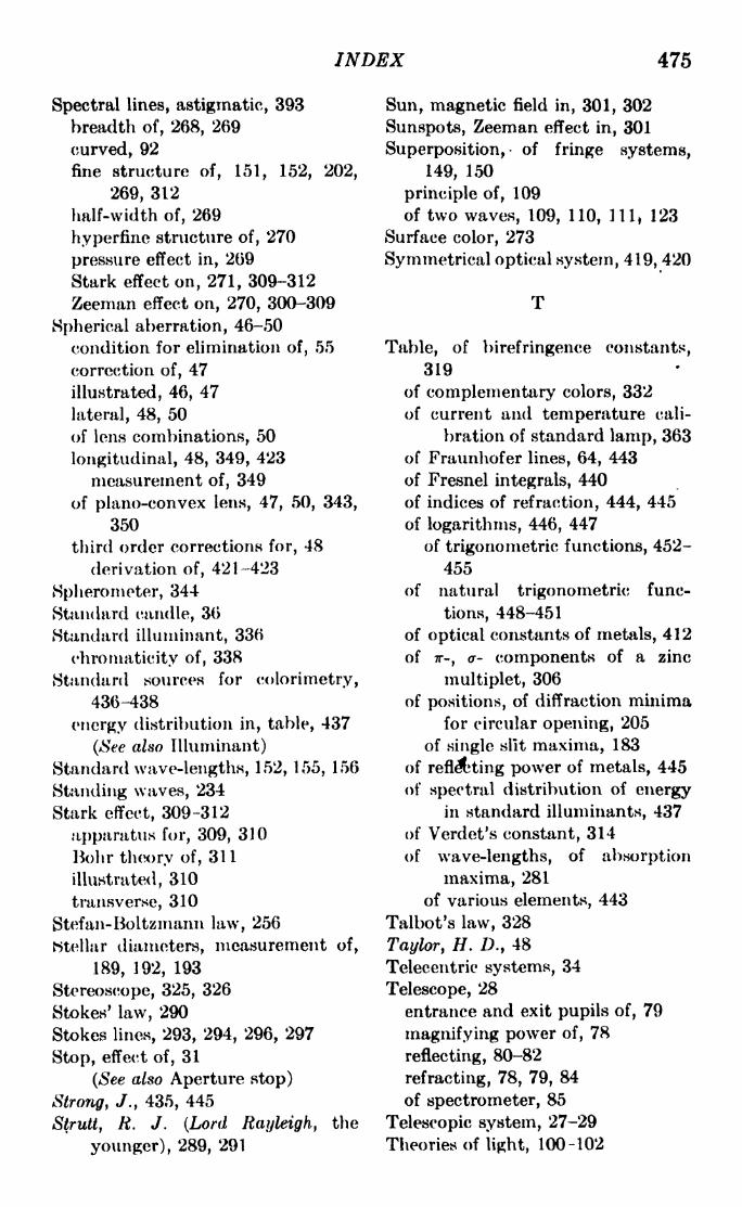
INDEX 475
Spectral lines, astigmatic, 393
breadth of, 268, 269
curved, 92
fine structure of, 151, 152, 202,
269, 312
half-width of, 269
hyperfiiie structure of, 270
pressure effect in, 2G9
Stark effect on, 271, 309-312
Zeeman effect on, 270, 300-309
Spherical aberration, 46-50
condition for elimination of, 55
correction of, 47
illustrated, 46, 47
lateral, 48, 50
of lens combinations, 50
longitudinal, 48, 349, 423
measurement of, 349
of plano-convex lens, 47, 50, 343,
350
third order corrections for, 48
derivation of, 421-423
Spherometer, 344
Standard candle, 30
Standard illuininant, 336
chrornaticity of, 338
Standard sources for colorimetry,
436-438
energy distribution in, table, 437
(See also Illuminant)
Standard wave-lengths, 152, 155, 156
Standing waves, 234
Stark effect, 309-312
apparatus for, 309, 310
Bohr theory of, 311
illustrated, 310
transverse, 310
Stefan-Boitzmann law, 256
htellar diameters, measurement of,
189, 192, 193
Stereoscope, 325, 326
Stokes' law, 290
Stokes lines, 293, 294, 296, 297
Stop, effect of, 31
(See also Aperture stop)
Strong, /., 435, 445
Strutt, R. J. (Lord Rayleigh, the
younger), 289, 291
Sun, magnetic field in, 301, 302
Sunspots, Zeeman effect in, 301
Superposition, of fringe systems,
149, 150
principle of, 109
of two waves, 109, 110, HI, 123
Surface color, 273
Symmetrical optical system, 419, 420
Table, of birefringence constants,
319
of complementary colors, 332
of current and temperature cali-
bration of standard lamp, 363
of Fraunhofer lines, 64, 443
of Fresnel integrals, 440
of indices of refraction, 444, 445
of logarithms, 446, 447
of trigonometric functions, 452-
455
of natural trigonometric func-
tions, 448-451
of optical constants of metals, 412
of TT-, a- components of a zinc
multiplet, 306
of positions, of diffraction minimafor circular opening, 205
of single slit maxima, 183
of reflating power of metals, 445
of spectral distribution of energyin standard illuminants, 437
of Verdet's constant, 314
of wave-lengths, of absorption
maxima, 281
of various elements, 443
Talbot's law, 328
Taylor, H. D., 48
Teleceutric systems, 34
Telescope, 28
entrance and exit pupils of, 79
magnifying power of, 78
reflecting, 80-82
refracting, 78, 79, 84
of spectrometer, 85
Telescopic system, 27-29
Theories of light, 100-102

476 JGHT: PRINCIPLES AND EXPERIMENTS
TV' d, colors in, 137
<3ns, derivation of equation
for, 19, 20
focal length of, 6, 20
optical axis of, 6
positions of astigmatic foci for, 52
spherical aberration of, 48, 50,
421-423
Thin lens system, 19-29
"acfirbmatic combination, 65, 66
focal length of, 6, 23, 26
Tint, 329
Toothed wheel, in velocity of light
measurement, 114
Total reflection, 96
Total-reflection prism, 96, 97, 193
Tourmaline, 215
index of refraction of, 445
Transverse vibration, direction of,
in crystals, 218, 219
and the electric force, 234
evidence for, 217
Trichromatic coefficients, 336, 338
Trichromatic theory of Young-
Helmholtz, 332, 333, 334
Tristimulus values, 336
Troland, L. T., 327
Twyinan, F. TV., 443
Tyndatt, J., 286
U
Uniaxial crystals, 215, 219, 226, 242,
243
experiments with, 395, 397, 398,
405
indices of refraction of, 445
Unit planes (see Principal planes)
Unpolarized light, nature of, 235
Urey, H. C., 311
Valasek, J., 285
van Biesbroeckj G. -A., 56
Velocity of light, in carbon bisul-
phide, 119
in crystals, 210, 222
Velocity of light, determinations of,
]
113-117' with Kerr cells, 321, 322
relation of, to frequency and
wave-length, 102
wave and group, 117-119
Verdet's constant, for carbon disul-
phide, 313
defined, 313
measurement of, 415
table of, 314
Vertical illuminators, 77
Vibration, plane of (see Plane of
vibration)
Visibility of interference fringes, 177,
179, 385
analysis of, 189-191
defined, 148, 157
in Fabry-Perot interferometer,
158'
in Michelson interferometer, 147-
152
minimum, 187, 389
in test for limit of resolution, 187
Visibility curves, 151, 152
Vision, binocular, 325
color, 331-334
functions of rods and cones in, 331
persistence of, 327, 328
stereoscopic, 326
Vaigt, W., 277
von Seidel, LM 46
W
Wave front, 110
in crystals, 211-214, 237-240
cylindrical, 169
pole of, 169
Wave and group velocity, 1 17-1 19
Wave-length determination, byFresnel biprism, 368-370
by single slit diffraction, 384-387
Wave-length standards, primary,
152, 155
secondary, 156
Wave-lengths, of absorption max-
ima, table of, 281

INDEX 477
Wave-lengths, ratio of, with Fabry-Perot interferometer, 382-384
with Michelson interferometer,380-382
of various elements, table of, 443Wave motion and light, 100, 102
(Characteristics of, 108, 109
displacement in, 108, 109
velocity of, 108
Wave-number, defined, 252
Wave plate, 223, 227Wave surface in biaxial crystals, 239
Wave-velocity surface, 211-215of calcite, illustrated, 214
Weierstrass, 57
White, H. L\, 253, 311
Whittaker, E. T., 46
Wieii displacement laws, 256
Wien distribution law, 257, 331, 362 -
Wiener, 234
Williams, R. C., 435
Williams, W. E., 135, 143, 156
Williams refractorneter, 135
Woliaston prism, 318, 358, 360
construction of, 221, 222
Wood, R. W., 168, 275, 292, 297, 362
Woodworth, C. W., 23
Yourig, Thomas, 57, 332
Young-Helmholtz theory, 332, 333,334
Young's apparatus, 126, 132
Young's construction, 57
Young's experiment, 125, 126
Z
Zeeman effect, 300-309
anomalous, 304, 305, 306-308in chromium, illustrated, 304
classical theory of, 302-304
energy levels in, 307, 308
inverse, 301
, normal, 305, 307
quantum theory of, 306-309in sunspots, illustrated, 301
Zeeman patterns, 304
anomalous, in sodium, 308in zinc, 305
normal triplet, 304Zero power lens combination, 81
Zone plate, 166, 167
Zones, Fresnel, 165, 166


Related Documents