Washington University in St. Louis Washington University in St. Louis Washington University Open Scholarship Washington University Open Scholarship Mechanical Engineering Design Project Class Mechanical Engineering & Materials Science Fall 12-10-2017 Light Activated Blinds Group K Light Activated Blinds Group K Griffin Beriont Washington University in St. Louis Kessashun Arthur Washington University in St. Louis Madeline Stadler Washington University in St. Louis Follow this and additional works at: https://openscholarship.wustl.edu/mems411 Part of the Mechanical Engineering Commons Recommended Citation Recommended Citation Beriont, Griffin; Arthur, Kessashun; and Stadler, Madeline, "Light Activated Blinds Group K" (2017). Mechanical Engineering Design Project Class. 75. https://openscholarship.wustl.edu/mems411/75 This Final Report is brought to you for free and open access by the Mechanical Engineering & Materials Science at Washington University Open Scholarship. It has been accepted for inclusion in Mechanical Engineering Design Project Class by an authorized administrator of Washington University Open Scholarship. For more information, please contact [email protected].

Welcome message from author
This document is posted to help you gain knowledge. Please leave a comment to let me know what you think about it! Share it to your friends and learn new things together.
Transcript

Washington University in St. Louis Washington University in St. Louis
Washington University Open Scholarship Washington University Open Scholarship
Mechanical Engineering Design Project Class Mechanical Engineering & Materials Science
Fall 12-10-2017
Light Activated Blinds Group K Light Activated Blinds Group K
Griffin Beriont Washington University in St. Louis
Kessashun Arthur Washington University in St. Louis
Madeline Stadler Washington University in St. Louis
Follow this and additional works at: https://openscholarship.wustl.edu/mems411
Part of the Mechanical Engineering Commons
Recommended Citation Recommended Citation Beriont, Griffin; Arthur, Kessashun; and Stadler, Madeline, "Light Activated Blinds Group K" (2017). Mechanical Engineering Design Project Class. 75. https://openscholarship.wustl.edu/mems411/75
This Final Report is brought to you for free and open access by the Mechanical Engineering & Materials Science at Washington University Open Scholarship. It has been accepted for inclusion in Mechanical Engineering Design Project Class by an authorized administrator of Washington University Open Scholarship. For more information, please contact [email protected].

Our final demonstration of our project did not fully meet our expectations, but we were able to meet the
majority of our performance goals. We were able to achieve a circuitry setup in which we had light being
received and transmitted to activate the motor to drive the motion of the blinds. We were able to keep the
overall design under our weight goal of approximately three pounds. We were also able to ensure that our
battery life was well able to perform more than 30 cycles of the light detection to movement process.
Meeting our performance goals posed a bigger issue than we had thought as we decided to use pure
circuitry instead of some type of Arduino Software. This made our overall process and execution more
complex although we were not able to fully succeed in accomplishing our performance goals. Another
key takeaway is that motors are more complex than we thought in regards to providing enough torque to
speed ratio. Since we were constrained to keep a small budget, we could not afford a motor that could
meet our needs by itself. After doing the initial demonstration of our prototype, we determined that we
should have designed a gear system that could have increased torque. Overall, we learned that the
planning and executing is a complex process that requires a lot of trial and error. In future projects, we
would definitely have planned multiple design build cycles to ensure the best possible results/product.
MEMS 411: Senior Design Project
Project Name
Kessashun Arthur
Griffin Beriont
Madeline Stadler

Project Name Introduction and Background Information
Page 1 of 35
TABLE OF CONTENTS
List of Figures ........................................................................................................................................... 4
List of Tables ............................................................................................................................................ 5
1 Introduction and Background Information............................................................................................ 6
1.1 Initial Project Description ............................................................................................................. 6
1.2 Existing Products .......................................................................................................................... 6
1.3 Relevant Patents ............................................................................................................................ 6
1.4 Codes & Standards ........................................................................................................................ 6
1.5 Project Scope ................................................................................................................................ 6
1.6 Project Planning ............................................................................................................................ 8
1.7 Realistic Constraints ..................................................................................................................... 8
1.7.1 Functional ............................................................................................................................. 8
1.7.2 Safety .................................................................................................................................... 8
1.7.3 Quality ................................................................................................................................... 9
1.7.4 Manufacturing ....................................................................................................................... 9
1.7.5 Timing ................................................................................................................................... 9
1.7.6 Economic .............................................................................................................................. 9
1.7.7 Ergonomic ............................................................................................................................. 9
1.7.8 Ecological ............................................................................................................................. 9
1.7.9 Aesthetic ............................................................................................................................... 9
1.7.10 Life Cycle .............................................................................................................................. 9
1.7.11 Legal ................................................................................................................................... 10
1.8 Revised Project Description ........................................................................................................ 10
2 Customer Needs & Product Specifications ......................................................................................... 10
2.1 Customer Interviews ................................................................................................................... 10
2.2 Interpreted Customer Needs........................................................................................................ 11
2.3 Target Specifications................................................................................................................... 12
3 Concept Generation ............................................................................................................................ 13
3.1 Functional Decomposition .......................................................................................................... 13
3.2 Morphological Chart ................................................................................................................... 14
3.3 Concept #1 – “Solinearcuit” ....................................................................................................... 15
Project Name Introduction and Background Information
Page 2 of 35
3.4 Concept #2 – “power provides rotation” ..................................................................................... 16
3.5 Concept #3 – “Lights, battery, action” ........................................................................................ 17
3.6 Concept #4 – “spins with the sun” .............................................................................................. 18
3.7 Concept #5 – “directurns” ........................................................................................................... 18
3.8 Concept #6 – “solar powered code monkey” .............................................................................. 19
4 Concept Selection ............................................................................................................................... 20
4.1 Concept Scoring Matrix .............................................................................................................. 20
4.2 Explanation of Winning Concept Scores .................................................................................... 20
4.3 Explanation of Second-Place Concept Scores ............................................................................ 21
4.4 Explanation of Third-Place Concept Scores ............................................................................... 21
4.5 Summary of Evaluation Results .................................................................................................. 21
5 Embodiment & Fabrication plan ......................................................................................................... 22
5.1 Exploded view with Bill of Materials ......................................................................................... 22
5.2 Isometric drawing with additional views .................................................................................... 23
6 Engineering Analysis .......................................................................................................................... 23
6.1 Engineering Analysis Results ..................................................................................................... 23
6.1.1 Motivation ........................................................................................................................... 23
6.1.2 Summary Statement of the Analysis ................................................................................... 23
6.1.3 Methodology ....................................................................................................................... 25
6.1.4 Results ................................................................................................................................. 25
6.1.5 Significance ......................................................................................................................... 25
6.2 Product Risk Assessment ............................................................................................................ 26
6.2.1 Risk Identification ............................................................................................................... 26
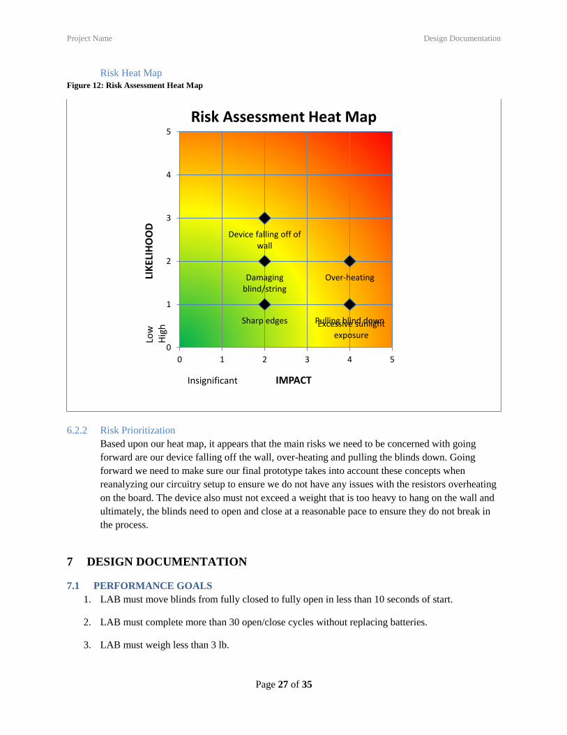
Risk Heat Map .................................................................................................................................... 27
6.2.2 Risk Prioritization ............................................................................................................... 27
7 Design Documentation ........................................................................................................................ 27
7.1 Performance Goals ...................................................................................................................... 27
7.2 Working Prototype Demonstration ............................................................................................. 28
7.2.1 Performance Evaluation ...................................................................................................... 28
7.2.2 Working Prototype – Video Link ........................................................................................ 28
7.2.3 Working Prototype – Additional Photos ............................................................................. 29
8 Discussion ........................................................................................................................................... 30
8.1 Design for Manufacturing – Part Redesign for Injection Molding ............................................. 30

Project Name Introduction and Background Information
Page 3 of 35
8.1.1 Draft Analysis Results ........................................................................................................ 30
8.1.2 Explanation of Design Changes .......................................................................................... 30
8.2 Design for Usability – Effect of Impairments on Usability ........................................................ 31
8.2.1 Vision .................................................................................................................................. 31
8.2.2 Hearing ................................................................................................................................ 31
8.2.3 Physical ............................................................................................................................... 31
8.2.4 Language ............................................................................................................................. 31
8.2 Overall Experience ...................................................................................................................... 31
8.2.1 Does your final project result align with the initial project description? ............................ 31
8.2.2 Was the project more or less difficult than you had expected? ........................................... 31
8.2.3 In what ways do you wish your final prototype would have performed better? ................. 32
8.2.4 Was your group missing any critical information when you evaluated concepts? ............. 32
8.2.5 Were there additional engineering analyses that could have helped guide your design? ... 32
8.2.6 How did you identify your most relevant codes and standards and how they influence
revision of the design? ........................................................................................................................ 32
8.2.7 What ethical considerations (from the Engineering Ethics and Design for Environment
seminar) are relevant to your device? How could these considerations be addressed? ...................... 32
8.2.8 On which part(s) of the design process should your group have spent more time? Which
parts required less time? ...................................................................................................................... 33
8.2.9 Was there a task on your Gantt chart that was much harder than expected? Were there any
that were much easier? ........................................................................................................................ 33
8.2.10 Was there a component of your prototype that was significantly easier or harder to
make/assemble than you expected? .................................................................................................... 33
8.2.11 If your budget were increased to 10x its original amount, would your approach have
changed? If so, in what specific ways? ............................................................................................... 33
8.2.12 If you were able to take the course again with the same project and group, what would you
have done differently the second time around? ................................................................................... 33
8.2.13 Were your team member’s skills complementary? ............................................................. 34
8.2.14 Was any needed skill missing from the group? .................................................................. 34
8.2.15 Has the project enhanced your design skills? ..................................................................... 34
8.2.16 Would you now feel more comfortable accepting a design project assignment at a job?... 34
8.2.17 Are there projects you would attempt now that you would not have attempted before? .... 34
9 Appendix A - Parts List ...................................................................................................................... 35
10 Appendix B - CAD Models ............................................................................................................ 35

Project Name Introduction and Background Information
Page 4 of 35
LIST OF FIGURES
Figure 1: Gantt Chart .................................................................................................................................... 8 Figure 2: Function tree for LAB ................................................................................................................. 13 Figure 3: Concept Design #1: Solinearcuit ................................................................................................. 15 Figure 4: Concept Design #2: Power Provides Rotation ............................................................................ 16 Figure 5: Concept Design #3: Lights, Battery, Action................................................................................ 17 Figure 6: Concept Design #4: Spins with the Sun ...................................................................................... 18 Figure 7: Concept Design #5: Directurns ................................................................................................... 18 Figure 8: Concept Design #6: Solar Powered Code Monkey ..................................................................... 19 Figure 9: Exploded View with Bill of Materials ......................................................................................... 22 Figure 10: Isometric Drawi
.................................................................................................................................................................... 23 Figure 11: Stresses Present on the Motor .................................................................................................... 25 Figure 12: Risk Assessment Heat Map ....................................................................................................... 27 Figure 13: Image of Final Prototype ........................................................................................................... 29 Figure 14: (Before) Draft Analysis Results ................................................................................................ 30 Figure 15: (After) Draft Analysis Results ................................................................................................... 30 Figure 16: Solidworks Model of Final Part ................................................................................................ 35

Project Name Introduction and Background Information
Page 5 of 35
LIST OF TABLES
Table 1: Target product specifications for light automated blinds.............................................................. 12 Table 2: Morphological Chart for LAB ...................................................................................................... 14 Table 3: Concept Scoring Matrix ................................................................................................................ 20 Table 4: Risk Prioritization ......................................................................................................................... 26 Table 5: Parts List ....................................................................................................................................... 35

Project Name Introduction and Background Information
Page 6 of 35
1 INTRODUCTION AND BACKGROUND INFORMATION
1.1 INITIAL PROJECT DESCRIPTION
The purpose of this project is to develop an attachable device to a pair of rolling blinds that will
automatically open them when sunlight is detected and close them when the sun goes down. This
device will promote energy efficiency during warmer and colder months. And be a commodity
for those who tend to forget to open close blinds.
1.2 EXISTING PRODUCTS
MOVE – blind and shade motorizer: This product uses a motor to open and close various
different kinds of shades and blinds that can be found in a typical household. It is easily installed,
small, but requires human operation to open and close. It attaches to the string of the blinds and
uses a pulley motion to raise and lower them.
1.3 RELEVANT PATENTS
N/A
1.4 CODES & STANDARDS
European Standard on Internal Blinds – Protection from strangulation hazards – Test Methods
(safety regulations for all blinds, windows, doors, & shutters)
1.5 PROJECT SCOPE
1. Write an overview of the purpose of the project
- The purpose of this project is to develop an attachable device to a pair of rolling blinds that
will automatically open them when sunlight is detected and close them when the sun goes
down. This device will promote energy efficiency during warmer and colder months. And be
a commodity for those who tend to forget to open close blinds.
2. Identify the customer for your eventual product
- Customers for this product would be average home/apartment owners, as well as businesses
with many windows that want to promote efficiency. Another potential market could be those
who have hard-to-reach blinds.
3. Specify the value or benefits to the customer
Project Name Introduction and Background Information
Page 7 of 35
- This will be an inexpensive device that will more than pay for itself long-term. Energy bills
can be reduced by using this device year-round, to compensate for most homeowners not
immediately opening and closing blinds at sunrise and sunset. Larger building/businesses can
see even greater savings over time. Beyond being a luxury, it requires no human interaction
after installation.
4. Define the project goals. A project goal statement should ideally be:
- The goal of the project is to produce a device that can easily be attached to an existing pair of
rolling blinds. This device will be able to roll up and unroll the blinds without any human
operation throughout the process. It will also be able to detect light and use the detection as
an indication of when to roll/unroll. Ideally the device will be light weight and easy to install;
no electrical connectivity will be necessary.
5. Identify what is in scope – what will the project accomplish?
- Some of the design factors that are in the scope of this project include the following:
i. Open and close blinds with motor use
ii. Light sensing component of a circuit to activate motor
iii. Connectivity to an existing pair of rolling blinds
iv. Casing that doesn’t expose any electrical components; little to no installation needed for
device
v. Battery usage if necessary
6. Identify what is out of scope – what will the project not accomplish?
- Some of the design factors that are not in the scope of this project include:
i. Fully run on solar power
ii. Remote to allow manual operation
iii. Wireless capabilities (mobile app)
iv. Calibration of which side of the house window is on us light intensity
v. Design to fit all types of blinds
7. Identify a few critical success factors for your project
- Some of the critical success factors for this project include:
i. Must roll and unroll a pair of blinds automatically
ii. Must remain attached or connected to a pair of blinds
iii. Must detect sunlight vs darkness
8. Identify project assumptions Identify items taken as being true for the purposes of planning a
project but could change later; think about the potential impact if the assumption prove to be false
- We assume that all rolling blinds have a uniform design and a similar size. We also assume
that all windows will have a reasonable amount of sunlight exposure. If these prove to be
false, we would have to adjust the sensitivity of out light detecting or accept that all windows
cannot use it. We would also have to make size adjustments or make a more versatile design.
9. Identify project constraints
- For the scope of our project, we are constrained with programming and software ability. We
cannot make a device that is very “home” compatible as many poplar modern products are.
We are constrained to a single type of blinds and a single method of opening and closing.
Testing also may be constrained as we cannot test the products functionality with natural light
at any point of the day or night.
10. Identify key project deliverables
Project Name Introduction and Background Information
Page 8 of 35
- Some of the key deliverables for this project included:
i. Open and close in a reasonable amount of time
ii. Size under 80 in2 per side
iii. Responds to sunlight detection
iv. Relatively cheap to produce; able to sell for $30
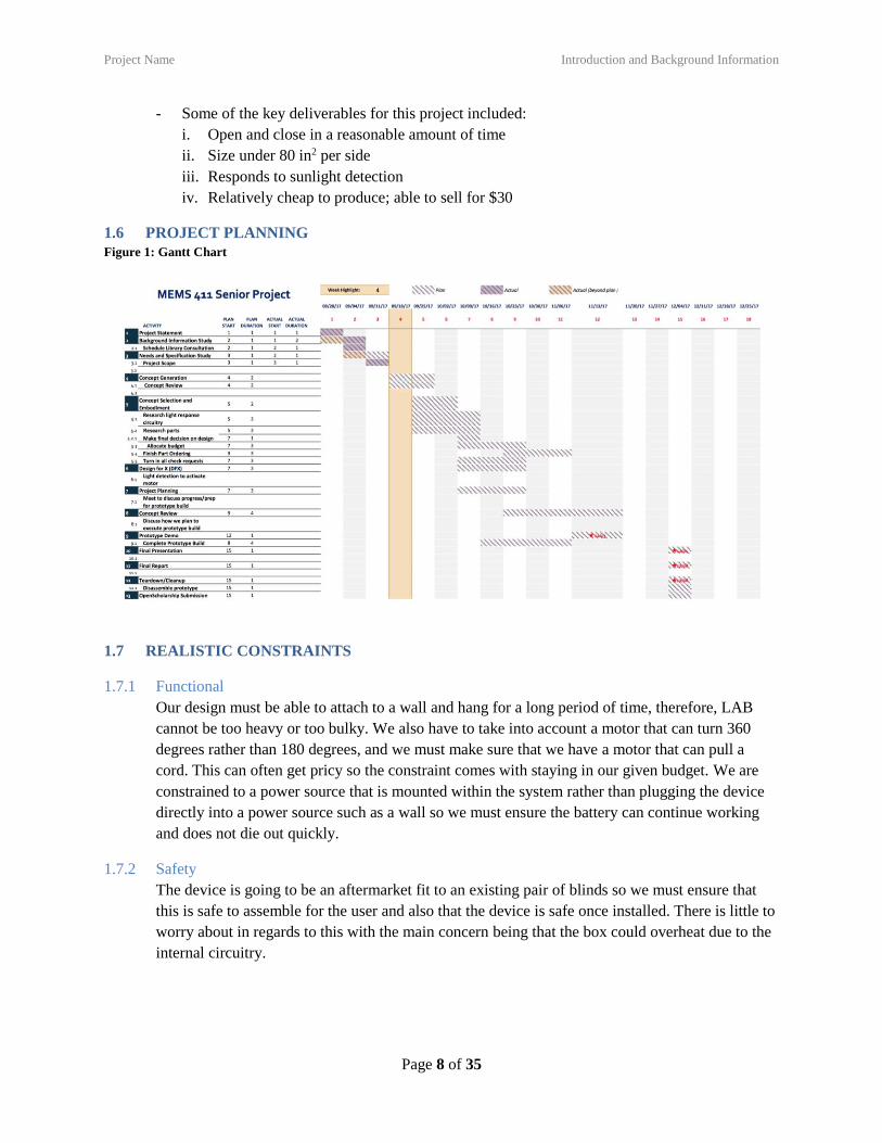
1.6 PROJECT PLANNING
Figure 1: Gantt Chart
1.7 REALISTIC CONSTRAINTS
1.7.1 Functional
Our design must be able to attach to a wall and hang for a long period of time, therefore, LAB
cannot be too heavy or too bulky. We also have to take into account a motor that can turn 360
degrees rather than 180 degrees, and we must make sure that we have a motor that can pull a
cord. This can often get pricy so the constraint comes with staying in our given budget. We are
constrained to a power source that is mounted within the system rather than plugging the device
directly into a power source such as a wall so we must ensure the battery can continue working
and does not die out quickly.
1.7.2 Safety
The device is going to be an aftermarket fit to an existing pair of blinds so we must ensure that
this is safe to assemble for the user and also that the device is safe once installed. There is little to
worry about in regards to this with the main concern being that the box could overheat due to the
internal circuitry.

Project Name Introduction and Background Information
Page 9 of 35
1.7.3 Quality
One of the standards that was applicable was that blinds can often be a choking hazard so we
must ensure that the attachment can be manually stopped. We also have to keep in mind that a lot
of small parts make up our part so these must be labeled as a potential choking hazard as well.
1.7.4 Manufacturing
We do not have any constraints involved with manufacturing as all of our parts are easy to find on
the market today, but we do not have the budget to mass produce the product. This is the only
constraint we have, but we are not too concerned, because we have the means to find all of the
parts required to build this device.
1.7.5 Timing
We are constrained to one semester to complete the entire project. We also are under a time
constraint for each assignment. This makes our design concept generation a very quick process to
ensure we can focus our efforts on perfecting that design through the semester. We also are given
two weeks to update our prototype after the initial presentation so we must work quickly to make
changes with little time to purchase new parts.
1.7.6 Economic
The biggest economic constraint is that we are provided a budget for this project. We have to be
able to find parts that are inexpensive in order to stay within that budget and also leave room in
case we must make improvements and have to last minute order parts. Mass manufacturing this
part would be ideal, but this is also a constraint, because this is extremely expensive compared to
that budget we are allotted. For example, many motors with high torque are available, but very
few are under hundreds of dollars.
1.7.7 Ergonomic
One of our biggest constraints was using internal circuitry. This required a lot of manual rewiring
rather than using a computer software where we could easily rewrite the code quickly.
1.7.8 Ecological
Our biggest constraint is trying to make a product with reusable or recyclable parts. Most of our
design is/ will meet this goal. The only issue we may have is that we plan to use a battery.
Batteries can be recycled, but most people just toss them into the trash can which is horrible for
the environment.
1.7.9 Aesthetic
This product is ideally for a residential home, therefore, the user is most likely looking for
something to blend in with their current home décor. We also want to make a product that is an
easy fit onto the wall and is out of the way. These are our constraints when trying to keep our
product pleasing for the consumer.
1.7.10 Life Cycle
We want to create a product that requires very little maintenance by the consumer, therefore,
having a durable device is required. We also want to ensure our battery remains working for a
long period of time so the user is not constantly changing it. Most of our parts must also be

Project Name Customer Needs & Product Specifications
Page 10 of 35
recyclable so that they do very little harm to the environment after the user is finished with the
product.
1.7.11 Legal
We must comply with the standard that states the blinds cannot be hazardous to the consumer
during operation. Other than this, there are not realistic constraints in regards to legal issues.
1.8 REVISED PROJECT DESCRIPTION
The goal of this project is to produce a device that can easily be attached to an existing pair of
rolling blinds. This device will be able to roll up and unroll the blinds without any human
operation throughout the process. It will also be able to detect light, and use this detection as an
indication of when to roll and unroll. This device will promote energy efficiency during warmer
and colder months and be a commodity for those who tend to forget to open and close the blinds.
2 CUSTOMER NEEDS & PRODUCT SPECIFICATIONS
2.1 CUSTOMER INTERVIEWS
1. Are the majority of your blinds within reach?
- Yes, most of them are in reachable spots.
2. Do you have any concerns about the solar panel versus manually rolling the blinds?
- Yes, what about days when the sun does not come up. I want to be able to manually open the
blinds if I have to. Yes, the sun does not hit the side of my house.
3. Do you have an issue with an added attachment on the current string that opens the blinds?
- I want it as small as it can be.
4. How fast should the blinds open? Does it even matter?
- I don’t want it fast, but I don’t want it slow. It should be a reasonable time frame that it takes for
the blinds to open and close.
5. Do you think this is convenient for people who may forget to shut their blinds in the evening?
- Yes. I make sure to shut my blinds so people cannot see in my house. I always get out of bed to
shut them if I realize I may have forgotten.
6. Is there a particular reason you prefer your blinds open during the day? Why?
- I open them to get sunlight into the house, because I t makes me feel better.
7. How much would you spend on a solar panel attachment that we are thinking about creating if
your blinds were in fact out of reach? Would you even spend the money on this?
- Oh wow! If I couldn’t reach them that would be bad. I probably would spend about $50 a
blind.
8. Would you also like a remote in case you feel like closing them during the day in case you want
to get rid of the light?
- Yes. That would be worth it to me.
9. Do you have any other capabilities you want to see from this sort of product?
- I have nothing else I would need. It if works, create it for other types of blinds systems.
Honestly, I just would really like the remote in case it is sunny an I want to take a nap.
10. I asked the interviewee for other questions he is thinking…
Project Name Customer Needs & Product Specifications
Page 11 of 35
- Can I control it with my phone? Are they all attached to one unit so they open in unison or is
this just for a single window panes blinds? Can I control it from my Bluetooth remote or an
app on my phone that I control from anywhere?
11. Do you think having only solar energy to activate is an issue?
- Yes. I think a battery backup is necessary. Sometimes we don’t get sunlight and people in
Seattle rally don’t get sunlight. Are you going to only sell this in Jamaica?
12. Do you think appearance is necessary to think about?
- Yes. My wife would not like this attachment to throw off the theme of the house so I need
different colors or I need to be able to paint it. I also don’t want that in the way when the
blinds shut.
13. Do you think this product would sell in a more commercialized setting rather than home settings?
- Absolutely. If I own a company, I want my blinds to open while we work and I want them to
close when no one is there. If I don’t have to remember to do that, that is an added bonus. Not
to mention, some companies cannot even reach their blinds that easy.
14. Do you prefer the blinds you have?
- Yes I like that I can tilt mine open. But like I said, in commercial settings, they want rolling
blinds, because they can clean them easy and also most are out of reach. You should make
this product geared towards a commercial buyer for a company.
2.2 INTERPRETED CUSTOMER NEEDS
1. Do you have any concerns about the solar panel versus manually rolling the blinds? - Yes, what
about days when the sun does not come up. I want to be able to manually open the blinds if I have
to. Yes, the sun does not hit the side of my house.
- LAB allows manual opening.
2. Do you have an issue with an added attachment on the current string that opens the blinds? - I
want it as small as it can be.
- LAB should be small and out of the way.
3. How fast should the blinds open? Does it even matter? - I don’t want it fast, but I don’t want it
slow. It should be a reasonable time frame that it takes for the blinds to open and close.
- LAB opens blinds at a reasonable pace.
4. Do you think this is convenient for people who may forget to shut their blinds in the evening? -
Yes. I make sure to shut my blinds so people cannot see in my house. I always get out of bed to
shut them if I realize I may have forgotten.
– LAB closes blinds when the sun goes down.
5. Is there a particular reason you prefer your blinds open during the day? Why? – I open them to
get sunlight into the house, because it makes me feel better.
6. How much would you spend on a solar panel attachment that we are thinking about creating if
your blinds were in fact out of reach? Would you even spend the money on this? – Oh wow! If I
couldn’t reach them that would be bad. I probably would spend about $50 a blind.
- LAB should be relatively inexpensive.
7. Would you also like a remote in case you feel like closing them during the day in case you want
to get rid of the light? – Yes. That would be worth it to me.
- LAB has remote control/ wall attachment should be available.

Project Name Customer Needs & Product Specifications
Page 12 of 35
8. Do you have any other capabilities you want to see from this sort of product? – I have nothing
else I would need. It if works, create it for other types of blinds systems. Honestly, I just would
really like the remote in case it is sunny an I want to take a nap.
- Remote available so blinds close without disrupting people from rest.
9. I asked the interviewee for other questions he is thinking…- Can I control it with my phone? Are
they all attached to one unit so they open in unison or is this just for a single window panes
blinds? Can I control it from my Bluetooth remote or an app on my phone that I control from
anywhere?
- LAB system contains wireless capabilities if not only light powered.
10. Do you think having only solar energy to activate is an issue? – Yes. I think a battery backup is
necessary. Sometimes we don’t get sunlight and people in Seattle rally don’t get sunlight. Are
you going to only sell this in Jamaica?
- LAB has an alternative way to open blinds.
11. Do you think appearance is necessary to think about? – Yes. My wife would not like this
attachment to throw off the theme of the house so I need different colors or I need to be able to
paint it. I also don’t want that in the way when the blinds shut.
- LAB is available in multiple colors or can be painted.
12. Do you think this product would sell in a more commercialized setting rather than home settings?
– absolutely. If I own a company, I want my blinds to open while we work and I want them to
close when no one is there. If I don’t have to remember to do that, that is an added bonus. Not to
mention, some companies cannot even reach their blinds that easy.
- LAB has completely automatic open/close setting.
13. Do you prefer the blinds you have? – Yes I like that I can tilt mine open. But like I said, in
commercial settings, they want rolling blinds, because they can clean them easy and also most are
out of reach. You should make this product geared towards a commercial buyer for a company.
- LAB is compatible with larger width blinds that exist in a company setting.
2.3 TARGET SPECIFICATIONS
Table 1: Target product specifications for light automated blinds.
Metric
Number
Associated
Needs Metric Units Acceptable Ideal
2 2 Area of the entire box in2 <80 <70
3 3 Time to open the blinds Seconds 8<x<10 6<x<8
4 4,8,9 Does the blind perform these
tasks? 1=yes,0=no 1 1
5 5 Cost for the consumer dollars <50 <30
6 10 Color options integers >1 >2
7 12
Torque to enable the blinds to
work with different size
blinds such as home vs
commercial settings
lbf/in 6<x<8 5<x<7
Project Name Concept Generation
Page 13 of 35
3 CONCEPT GENERATION
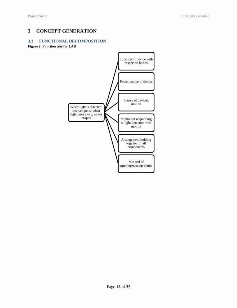
3.1 FUNCTIONAL DECOMPOSITION
Figure 2: Function tree for LAB
When light is detected, device opens; when
light goes away, motor stopes
Location of device with respect to blinds
Power source of device
Source of device's motion
Method of responding to light detection with
motion
Arrangement/holding together of all components
Method of opening/closing blinds
Project Name Concept Generation
Page 14 of 35
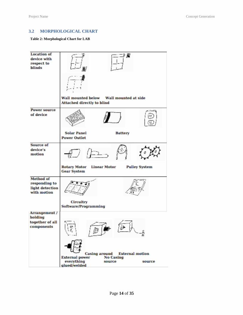
3.2 MORPHOLOGICAL CHART
Table 2: Morphological Chart for LAB
Project Name Concept Generation
Page 15 of 35
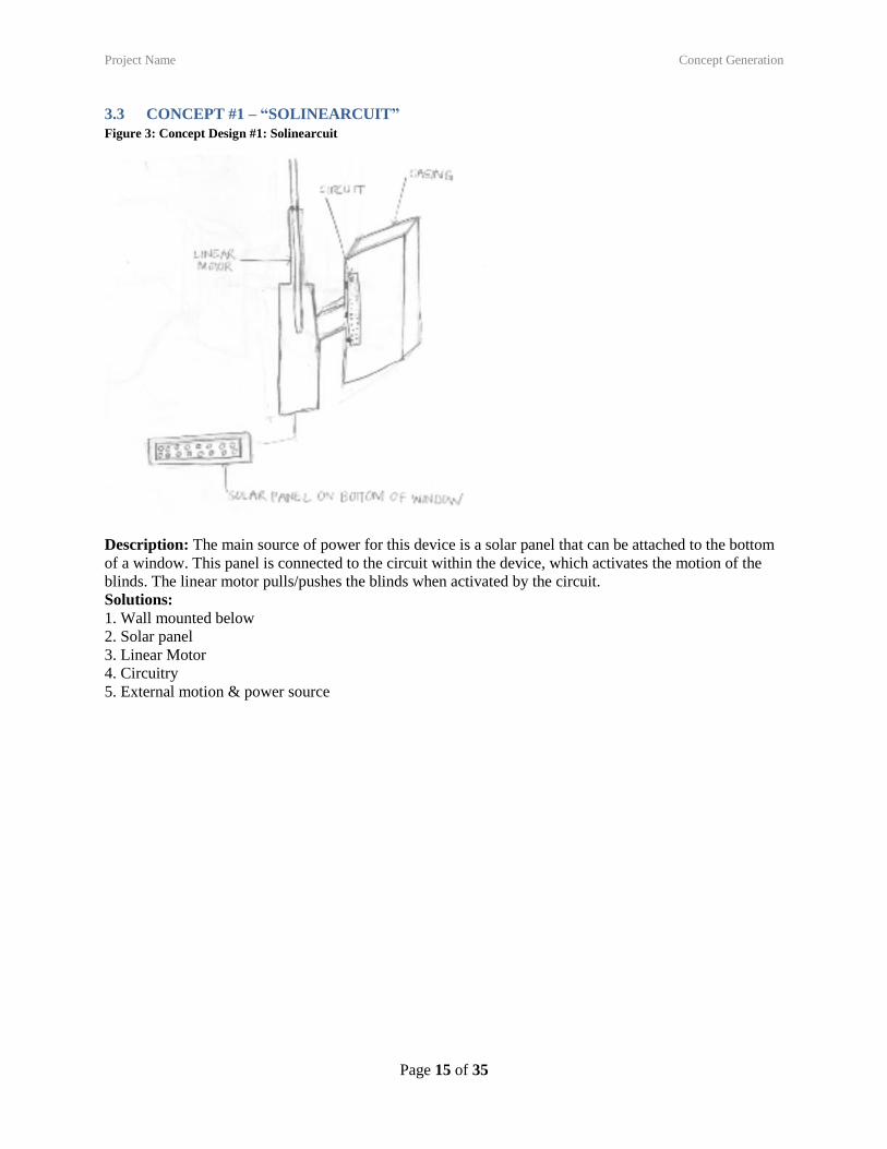
3.3 CONCEPT #1 – “SOLINEARCUIT”
Figure 3: Concept Design #1: Solinearcuit
Description: The main source of power for this device is a solar panel that can be attached to the bottom
of a window. This panel is connected to the circuit within the device, which activates the motion of the
blinds. The linear motor pulls/pushes the blinds when activated by the circuit.
Solutions:
1. Wall mounted below
2. Solar panel
3. Linear Motor
4. Circuitry
5. External motion & power source
Project Name Concept Generation
Page 16 of 35
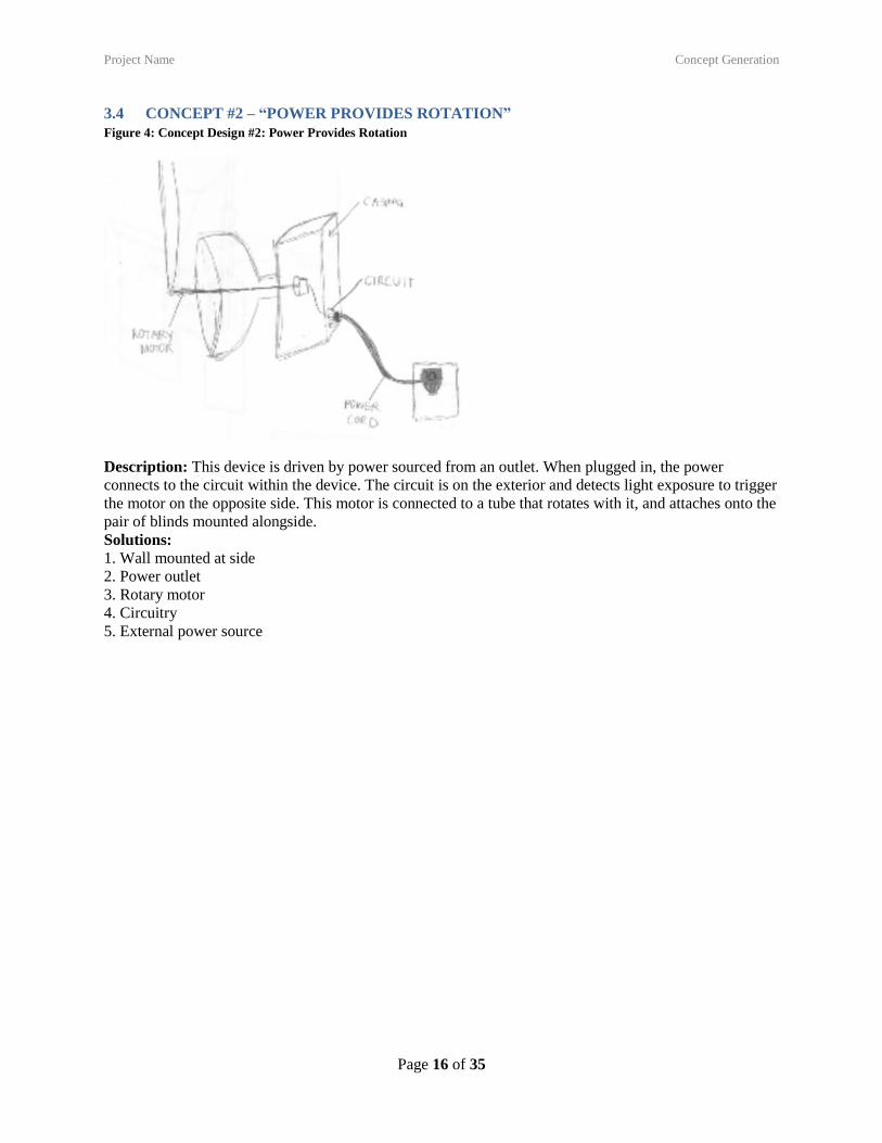
3.4 CONCEPT #2 – “POWER PROVIDES ROTATION”
Figure 4: Concept Design #2: Power Provides Rotation
Description: This device is driven by power sourced from an outlet. When plugged in, the power
connects to the circuit within the device. The circuit is on the exterior and detects light exposure to trigger
the motor on the opposite side. This motor is connected to a tube that rotates with it, and attaches onto the
pair of blinds mounted alongside.
Solutions:
1. Wall mounted at side
2. Power outlet
3. Rotary motor
4. Circuitry
5. External power source

Project Name Concept Generation
Page 17 of 35
3.5 CONCEPT #3 – “LIGHTS, BATTERY, ACTION”
Figure 5: Concept Design #3: Lights, Battery, Action
Description: This device is attached to the wall beneath the pair of blinds. It has a circuit internally that
converts light detection to rotary motion with the motor. The photo diode is exposed to the outside light
through a small window at the top of the device, and the motor is on the outside. The motor has a clip
where the string of a blind can be attached and wind the blind up and down when activated.
Solutions:
1. Wall mounted below
2. Battery
3. Rotary motor
4. Circuitry
5. External motor

Project Name Concept Generation
Page 18 of 35
3.6 CONCEPT #4 – “SPINS WITH THE SUN”
Figure 6: Concept Design #4: Spins with the Sun
Description: This device is mounted on the wall alongside the blind. It has a cone shaped attachment that
allows it to connect to the “tube” of blinds of various sizes. A solar panel hangs beneath it with adhesive
that allows it to be attached directly to the window. The device is programmed with software that
activates the internal motor connected to the tube when solar power is first received from the panel, and
vice versa when light goes away.
Solutions:
1. Wall mounted at side
2. Solar panel
3. Rotary motor
4. Software/programming
5. Casing around everything
3.7 CONCEPT #5 – “DIRECTURNS”
Figure 7: Concept Design #5: Directurns
Project Name Concept Generation
Page 19 of 35
Description: This design attaches directly to the blinds with a rotary motor turning the tube to open and
close the blinds. The motor is activated using circuitry to register the sunlight. All components are within
a square casing, with an external power source of a power outlet.
Solution:
1. Attached directly to blind
2. Power outlet
3. Rotary motor
4. Circuitry
5. External power source
3.8 CONCEPT #6 – “SOLAR POWERED CODE MONKEY”
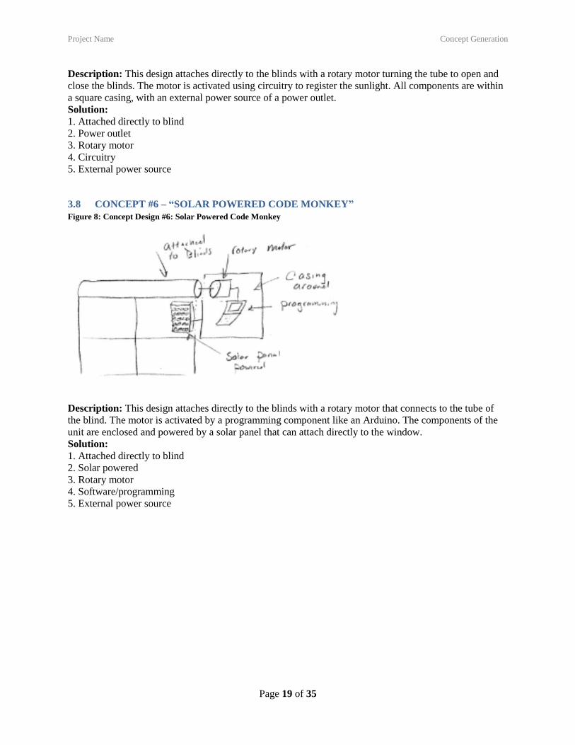
Figure 8: Concept Design #6: Solar Powered Code Monkey
Description: This design attaches directly to the blinds with a rotary motor that connects to the tube of
the blind. The motor is activated by a programming component like an Arduino. The components of the
unit are enclosed and powered by a solar panel that can attach directly to the window.
Solution:
1. Attached directly to blind
2. Solar powered
3. Rotary motor
4. Software/programming
5. External power source
Project Name Concept Selection
Page 20 of 35
4 CONCEPT SELECTION
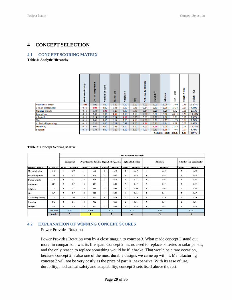
4.1 CONCEPT SCORING MATRIX
Table 2: Analytic Hierarchy
Table 3: Concept Scoring Matrix
4.2 EXPLANATION OF WINNING CONCEPT SCORES
Power Provides Rotation
Power Provides Rotation won by a close margin to concept 3. What made concept 2 stand out
more, in comparison, was its life span. Concept 2 has no need to replace batteries or solar panels,
and the only reason to replace something would be if it broke. That would be a rare occasion,
because concept 2 is also one of the most durable designs we came up with it. Manufacturing
concept 2 will not be very costly as the price of part is inexpensive. With its ease of use,
durability, mechanical safety and adaptability, concept 2 sets itself above the rest.
Project Name Concept Selection
Page 21 of 35
4.3 EXPLANATION OF SECOND-PLACE CONCEPT SCORES
Lights, Battery, Action
Lights, Battery, Action powered came in a close second to concept 2. One of the reasons that it
fell to concept 2 was its lifespan. In our scoring matrix, Concept 3 had a lifespan score of 3 while
concept 2 had a lifespan score of 5. What helped to put this concept in second place was its
adaptability, durability, size, and mechanical safety. The design is adaptable and durable due to
its casing component, and ability to be moved from point A to point B in one piece. The size also
makes it easy to move as well as hang from the wall without falling. Most of these designs are
very safe, because they are out of the way of the user. The Its cost of parts, and number of parts,
gave it low scores in those aspects respectively; however, the other areas that it excels in
outweighs those two factors.
4.4 EXPLANATION OF THIRD-PLACE CONCEPT SCORES
Solinearcuit
Solinearcuit came in third place. Concept 1 excels in adaptability and durability; however, where
it as its pitfalls is in lifespan and cost of parts. Even though it has a smaller lifespan and a higher
cost of parts in comparison to concept 2 and 3, it scores much better than concept 4, 5, and 6. This
has to do with the number of parts that are involved, the size, ease of use, and mechanical safety.
Where this product will be hard to accomplish is the solar panel. In general, solar panels are very
pricy, which is why this design did not score very high in regards to cost of components. As our
budget is limited, we will want our spending on other components to assure we can keep within
the given budget.
4.5 SUMMARY OF EVALUATION RESULTS
The most important criterion was safety which is quite important when building any piece of
machinery. The user must not be worried about getting injured throughout the process of using
the product. Ease of use and durability were also weighted very high. The user must be able to
use the product easily or else they will more than likely end up returning it. This idea also goes
along with durability. If the product does not hold up, then the user will be angry and more than
likely argue for their money back. Taking a look at the design concepts, it appears that the most
valuable to least valuable were as follows: the rotary motor wall powered, rotary motor battery
powered, linear motor puller, rotary motor with solar panel, direct attachment of rotary motor
with power cord and finally, the direct attachment with the solar panel and computerized
software.
Project Name Embodiment & Fabrication plan
Page 22 of 35
5 EMBODIMENT & FABRICATION PLAN
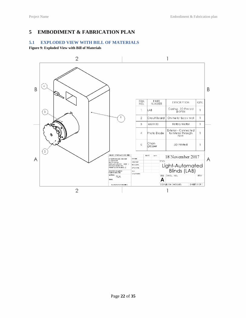
5.1 EXPLODED VIEW WITH BILL OF MATERIALS
Figure 9: Exploded View with Bill of Materials
Project Name Engineering Analysis
Page 23 of 35
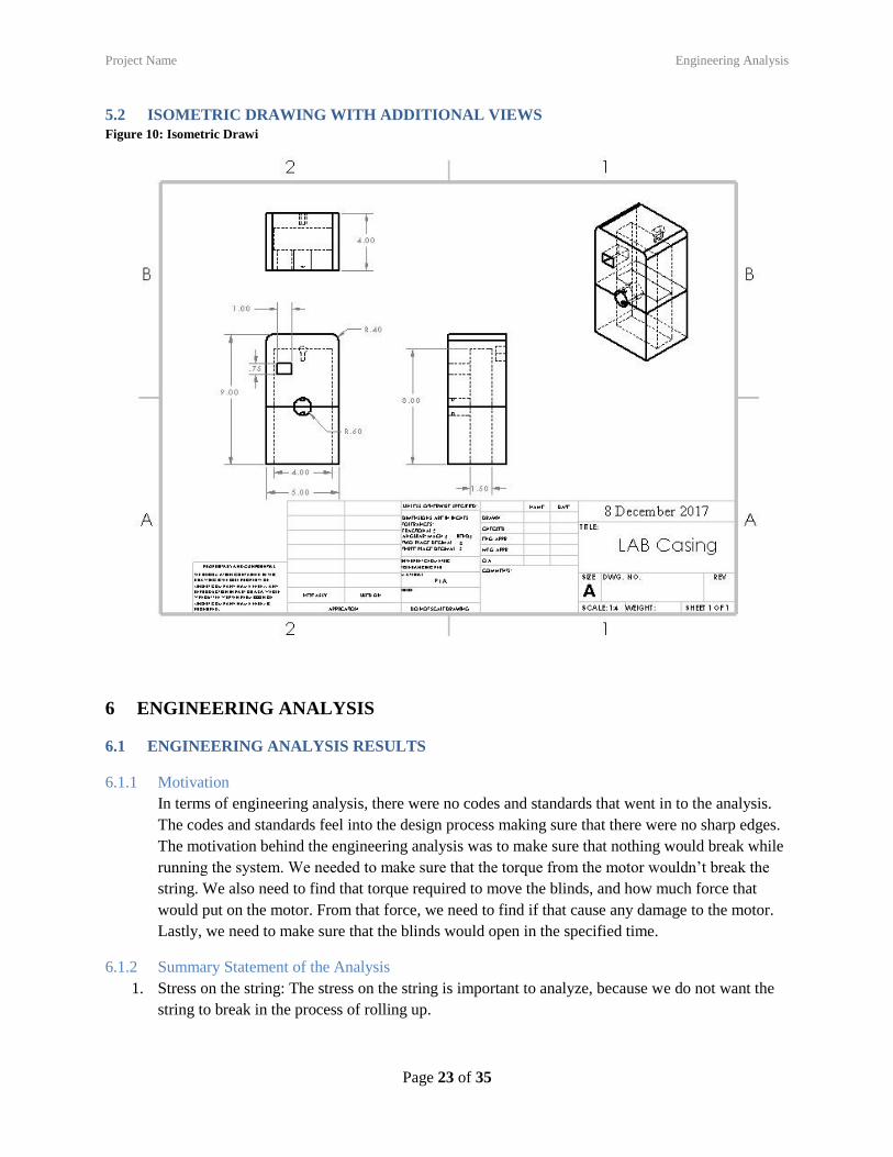
5.2 ISOMETRIC DRAWING WITH ADDITIONAL VIEWS
Figure 10: Isometric Drawi
6 ENGINEERING ANALYSIS
6.1 ENGINEERING ANALYSIS RESULTS
6.1.1 Motivation
In terms of engineering analysis, there were no codes and standards that went in to the analysis.
The codes and standards feel into the design process making sure that there were no sharp edges.
The motivation behind the engineering analysis was to make sure that nothing would break while
running the system. We needed to make sure that the torque from the motor wouldn’t break the
string. We also need to find that torque required to move the blinds, and how much force that
would put on the motor. From that force, we need to find if that cause any damage to the motor.
Lastly, we need to make sure that the blinds would open in the specified time.
6.1.2 Summary Statement of the Analysis
1. Stress on the string: The stress on the string is important to analyze, because we do not want the
string to break in the process of rolling up.
Project Name Engineering Analysis
Page 24 of 35
𝜎𝑠𝑡𝑟𝑖𝑛𝑔 =𝐹
𝐴
𝐴 = 𝜋𝑟2 = 0.093 𝑖𝑛2
𝐹 = 20𝑙𝑏𝑠
𝜎𝑠𝑡𝑟𝑖𝑛𝑔 = 215.19 𝑙𝑏𝑠
2. The torque required to move the blinds: If the motor is moving too fast or too slow, the product
will not work. If we can determine the torque required, we can ensure the blinds will roll up
correctly.
𝑇 = 𝑟 × 𝐹 = 40𝑙𝑏𝑠
The radius of the pulley is 2 inches. We tested a 20 pound weight attached to the string and it
would move the blinds. So the torque is a simple equation, and it comes back to 40lbs required to
move the blinds.
3. The speed to move the blinds: The overall time that the blinds need to roll up within is one of our
performance goals so we must calculate this accurately to ensure we are getting the motor to
move at the right speed to make our time goal.
𝑉 =𝐿
𝑡 𝐿 = 6𝑓𝑡 = 72 𝑖𝑛 𝑡 = 10𝑠
𝑉 = 7.2𝑖𝑛
𝑠
𝜔 =𝑉
𝑟 𝑟 = 2𝑖𝑛 𝜔 = 3.6 𝑟𝑎𝑑𝑠
𝑠⁄
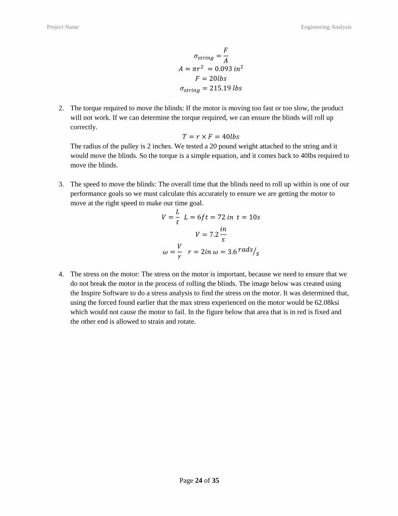
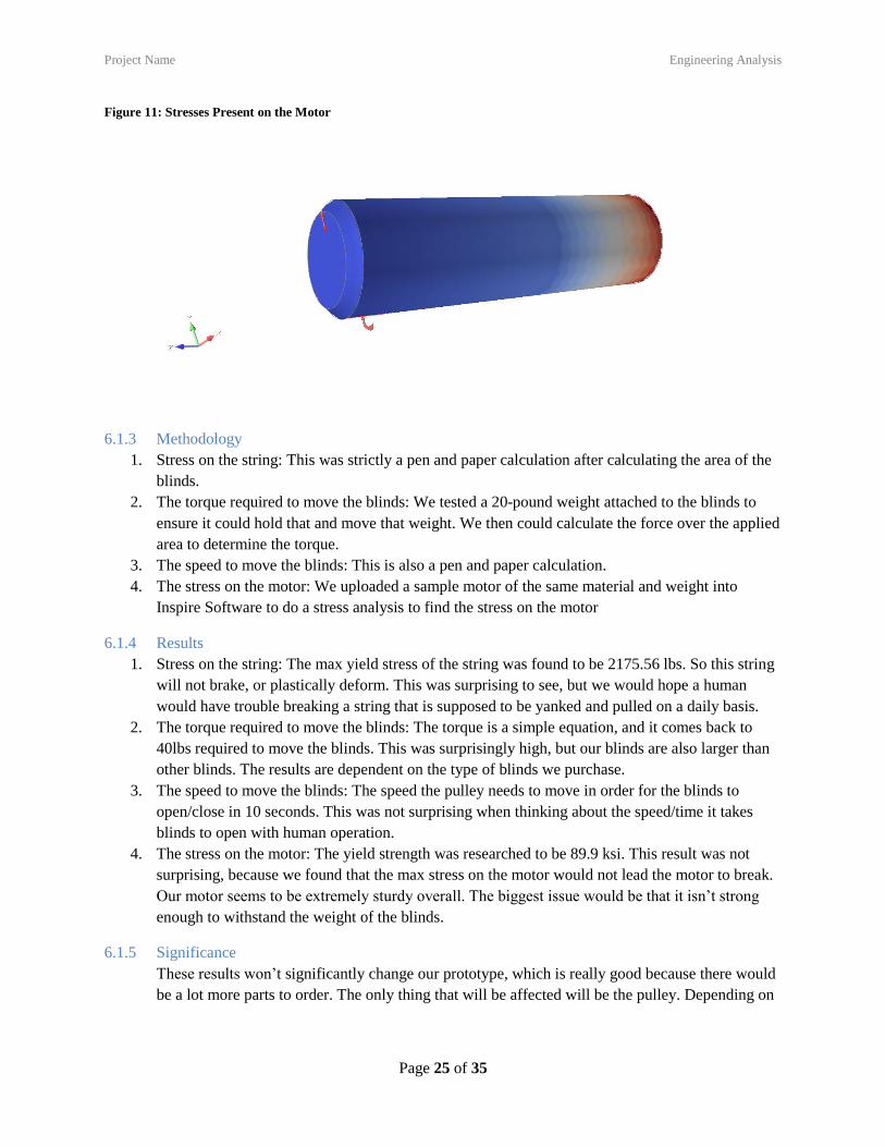
4. The stress on the motor: The stress on the motor is important, because we need to ensure that we
do not break the motor in the process of rolling the blinds. The image below was created using
the Inspire Software to do a stress analysis to find the stress on the motor. It was determined that,
using the forced found earlier that the max stress experienced on the motor would be 62.08ksi
which would not cause the motor to fail. In the figure below that area that is in red is fixed and
the other end is allowed to strain and rotate.
Project Name Engineering Analysis
Page 25 of 35
Figure 11: Stresses Present on the Motor
6.1.3 Methodology
1. Stress on the string: This was strictly a pen and paper calculation after calculating the area of the
blinds.
2. The torque required to move the blinds: We tested a 20-pound weight attached to the blinds to
ensure it could hold that and move that weight. We then could calculate the force over the applied
area to determine the torque.
3. The speed to move the blinds: This is also a pen and paper calculation.
4. The stress on the motor: We uploaded a sample motor of the same material and weight into
Inspire Software to do a stress analysis to find the stress on the motor
6.1.4 Results
1. Stress on the string: The max yield stress of the string was found to be 2175.56 lbs. So this string
will not brake, or plastically deform. This was surprising to see, but we would hope a human
would have trouble breaking a string that is supposed to be yanked and pulled on a daily basis.
2. The torque required to move the blinds: The torque is a simple equation, and it comes back to
40lbs required to move the blinds. This was surprisingly high, but our blinds are also larger than
other blinds. The results are dependent on the type of blinds we purchase.
3. The speed to move the blinds: The speed the pulley needs to move in order for the blinds to
open/close in 10 seconds. This was not surprising when thinking about the speed/time it takes
blinds to open with human operation.
4. The stress on the motor: The yield strength was researched to be 89.9 ksi. This result was not
surprising, because we found that the max stress on the motor would not lead the motor to break.
Our motor seems to be extremely sturdy overall. The biggest issue would be that it isn’t strong
enough to withstand the weight of the blinds.
6.1.5 Significance
These results won’t significantly change our prototype, which is really good because there would
be a lot more parts to order. The only thing that will be affected will be the pulley. Depending on
Project Name Engineering Analysis
Page 26 of 35
how our test preform under these analyses will determine if the pulley would need to be changed.
The pulley will contribute to the most torque.
6.2 PRODUCT RISK ASSESSMENT
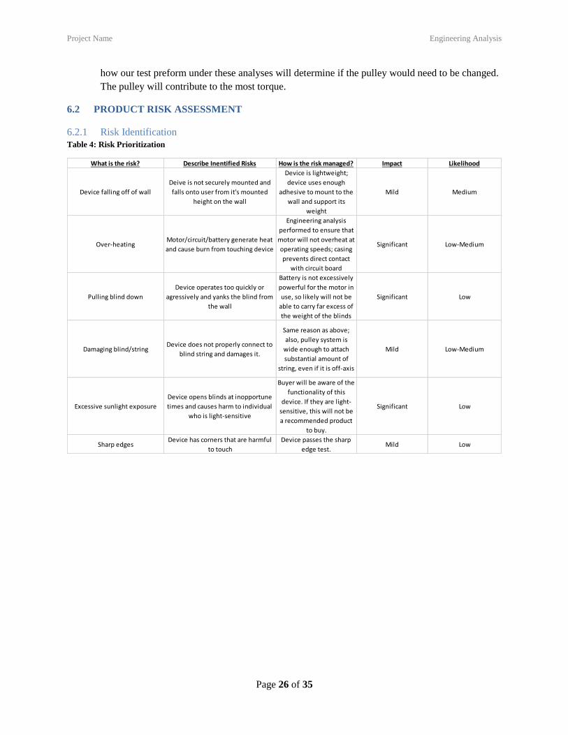
6.2.1 Risk Identification
Table 4: Risk Prioritization
What is the risk? Describe Inentified Risks How is the risk managed? Impact Likelihood
Device falling off of wall
Deive is not securely mounted and
falls onto user from it's mounted
height on the wall
Device is lightweight;
device uses enough
adhesive to mount to the
wall and support its
weight
Mild Medium
Over-heatingMotor/circuit/battery generate heat
and cause burn from touching device
Engineering analysis
performed to ensure that
motor will not overheat at
operating speeds; casing
prevents direct contact
with circuit board
Significant Low-Medium
Pulling blind down
Device operates too quickly or
agressively and yanks the blind from
the wall
Battery is not excessively
powerful for the motor in
use, so likely will not be
able to carry far excess of
the weight of the blinds
Significant Low
Damaging blind/stringDevice does not properly connect to
blind string and damages it.
Same reason as above;
also, pulley system is
wide enough to attach
substantial amount of
string, even if it is off-axis
Mild Low-Medium
Excessive sunlight exposure
Device opens blinds at inopportune
times and causes harm to individual
who is light-sensitive
Buyer will be aware of the
functionality of this
device. If they are light-
sensitive, this will not be
a recommended product
to buy.
Significant Low
Sharp edgesDevice has corners that are harmful
to touch
Device passes the sharp
edge test.Mild Low
Project Name Design Documentation
Page 27 of 35
Risk Heat Map
Figure 12: Risk Assessment Heat Map
6.2.2 Risk Prioritization
Based upon our heat map, it appears that the main risks we need to be concerned with going
forward are our device falling off the wall, over-heating and pulling the blinds down. Going
forward we need to make sure our final prototype takes into account these concepts when
reanalyzing our circuitry setup to ensure we do not have any issues with the resistors overheating
on the board. The device also must not exceed a weight that is too heavy to hang on the wall and
ultimately, the blinds need to open and close at a reasonable pace to ensure they do not break in
the process.
7 DESIGN DOCUMENTATION
7.1 PERFORMANCE GOALS
1. LAB must move blinds from fully closed to fully open in less than 10 seconds of start.
2. LAB must complete more than 30 open/close cycles without replacing batteries.
3. LAB must weigh less than 3 lb.
Device falling off of wall
Over-heating
Pulling blind down
Damaging blind/string
Excessive sunlight exposure
Sharp edges
0
1
2
3
4
5
0 1 2 3 4 5
LIK
ELIH
OO
D
IMPACT
Risk Assessment Heat Map
Insignificant
Low
Hig
h
Project Name Design Documentation
Page 28 of 35
4. LAB must complete one closed-open-closed cycle with unmodified test blinds and with 50%
load/torque added to strings/cords.
5. LAB must not fail accessible surface temperature test as defined in CPSC child safety standard,
after 2 minutes of on/off cycles.
7.2 WORKING PROTOTYPE DEMONSTRATION
7.2.1 Performance Evaluation
We were able to meet the 3 of our performance goals. The first that succeeded very well was the
prototype ran 30 cycles without changing the battery. Throughout all the test, the battery never
needed to be changed. The second was that the prototype weighed less than 3 pounds. This was
easy to meet because we decided to 3-D print the casing to decrease the weight. The third
performance goal that we accomplished, was the prototype did not exceed heat requirements.
There was never a time that the circuit had overheated or even came close to the temperature.
There were two performance goals that we did not achieve. The first that the blinds would roll up
then down with 50% more torque. The reason why this wasn’t met was because we weren’t able
to get the blinds to close. We wanted to challenge ourselves by using circuitry instead of a micro
controller. We failed to get our logic correct. In an idea situation, our logic would allow for the
blinds to close when light wasn’t detected. The last performance goal that we didn’t complete was
that the blinds would close in 10 seconds. This wasn’t met because our motor had enough torque
to pull the blinds, but the speed wasn’t fast enough. We believe that if there was more time to
complete the prototype, all of our performance goals would be met.
7.2.2 Working Prototype – Video Link
Final Demonstration and Evaluation of Project
Project Name Design Documentation
Page 29 of 35
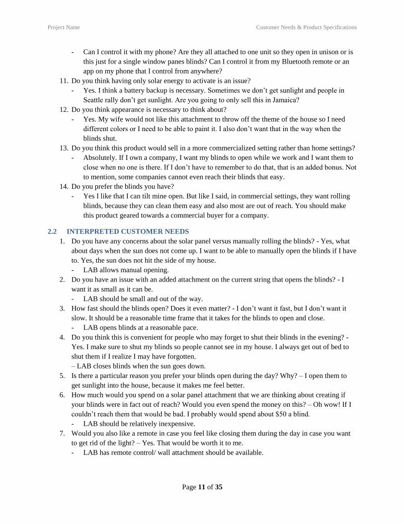
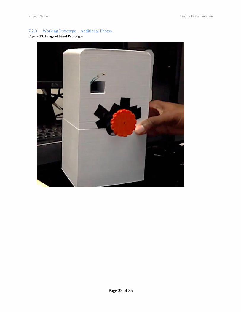
7.2.3 Working Prototype – Additional Photos
Figure 13: Image of Final Prototype

Project Name Discussion
Page 30 of 35
8 DISCUSSION
8.1 DESIGN FOR MANUFACTURING – PART REDESIGN FOR INJECTION MOLDING
8.1.1 Draft Analysis Results
Figure 14: (Before) Draft Analysis Results
Figure 15: (After) Draft Analysis Results
8.1.2 Explanation of Design Changes
Pictured above are the before and after draft analyses of the casing for our design. Our original
design was very square, with sharp edges, and inconsistent wall thicknesses due to the interior
holes for the circuit board and the motor. The re-design added a draft angle on all sides and
eliminated the extrusion to mount a pulley. This would require us to attach a pulley directly to the
motor instead; it would also require our design to have an external circuit instead of an internal
attachment to the back wall. There is still a small amount of negative draft remaining in the hole
Project Name Discussion
Page 31 of 35
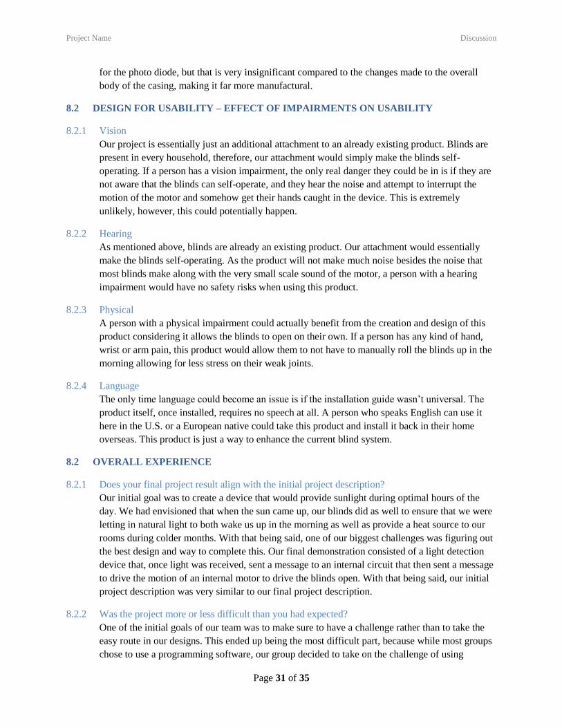
for the photo diode, but that is very insignificant compared to the changes made to the overall
body of the casing, making it far more manufactural.
8.2 DESIGN FOR USABILITY – EFFECT OF IMPAIRMENTS ON USABILITY
8.2.1 Vision
Our project is essentially just an additional attachment to an already existing product. Blinds are
present in every household, therefore, our attachment would simply make the blinds self-
operating. If a person has a vision impairment, the only real danger they could be in is if they are
not aware that the blinds can self-operate, and they hear the noise and attempt to interrupt the
motion of the motor and somehow get their hands caught in the device. This is extremely
unlikely, however, this could potentially happen.
8.2.2 Hearing
As mentioned above, blinds are already an existing product. Our attachment would essentially
make the blinds self-operating. As the product will not make much noise besides the noise that
most blinds make along with the very small scale sound of the motor, a person with a hearing
impairment would have no safety risks when using this product.
8.2.3 Physical
A person with a physical impairment could actually benefit from the creation and design of this
product considering it allows the blinds to open on their own. If a person has any kind of hand,
wrist or arm pain, this product would allow them to not have to manually roll the blinds up in the
morning allowing for less stress on their weak joints.
8.2.4 Language
The only time language could become an issue is if the installation guide wasn’t universal. The
product itself, once installed, requires no speech at all. A person who speaks English can use it
here in the U.S. or a European native could take this product and install it back in their home
overseas. This product is just a way to enhance the current blind system.
8.2 OVERALL EXPERIENCE
8.2.1 Does your final project result align with the initial project description?
Our initial goal was to create a device that would provide sunlight during optimal hours of the
day. We had envisioned that when the sun came up, our blinds did as well to ensure that we were
letting in natural light to both wake us up in the morning as well as provide a heat source to our
rooms during colder months. With that being said, one of our biggest challenges was figuring out
the best design and way to complete this. Our final demonstration consisted of a light detection
device that, once light was received, sent a message to an internal circuit that then sent a message
to drive the motion of an internal motor to drive the blinds open. With that being said, our initial
project description was very similar to our final project description.
8.2.2 Was the project more or less difficult than you had expected?
One of the initial goals of our team was to make sure to have a challenge rather than to take the
easy route in our designs. This ended up being the most difficult part, because while most groups
chose to use a programming software, our group decided to take on the challenge of using
Project Name Discussion
Page 32 of 35
internal circuitry to transfer the signal from the photo diode to drive the motor. This was
extremely difficult as we had to ensure our motor had just enough torque to drive the blinds open,
and we also had to ensure that the entire circuit was correct and intact when putting the final
device together. We also learned a lot of trial and error when it comes to choosing motor wisely.
We realized very late in the project that torque is more important than speed in our case, which
forced us to work diligently to alter our design as well as obtain a new motor. Overall, this project
seemed less difficult at the beginning of the semester, but posed a lot more difficult than we
initially thought possible.
8.2.3 In what ways do you wish your final prototype would have performed better?
As a group, we really were a bit disappointed with our final prototype demonstration. When
thinking back on the initial design concepts, we realized that for our project in particular, it would
have been wise to use a computerized software rather than internal circuitry. This is due to the
fact that we would have been able to focus more on ensuring our motor was working properly and
in a timely manner. We also wish we would have created our device for a simpler type of blind.
The motor we used required a lot of torque to lift the blinds whereas a simple device with a way
to twist blinds via a rod maybe have been a bit easier.
8.2.4 Was your group missing any critical information when you evaluated concepts?
One of the things we underestimated in the initial evaluation of concepts was the complexity of
trying to create an internal circuit board with multiple inputs. We would have benefitted greatly
from a computer program, but due to the initial thought that we wanted to use our engineering
courses from the past, we decided to take on the challenge of using an internal circuit board.
Another design concept we overlooked was the fact that the blinds we decided to use are very
heavy to open so we probably should have looked at a different type of blinds system that did not
require a heavy weight to be vertically lifted.
8.2.5 Were there additional engineering analyses that could have helped guide your design?
The only additional engineering analysis we could have potentially spent more time on was a
deeper analysis of the particular type of motor we used. We were using a motor that has
extremely high speed, but unfortunately very little torque.
8.2.6 How did you identify your most relevant codes and standards and how they influence revision of
the design?
Most of our codes and standards that were relevant were in regards to safety. One in particular
was that the strings on the blinds could not be considered a choking hazard. This was taken into
account when analyzing the speed of rolling the blinds up. This was the only way this influenced
our design process.
8.2.7 What ethical considerations (from the Engineering Ethics and Design for Environment seminar)
are relevant to your device? How could these considerations be addressed?
The ethical considerations that are most closely related are the ones in terms of utilizing the
natural resources we have such as solar energy, for example. We initially talked about making our
design with a solar panel to capture the energy from the sun to then convert it to mechanical
energy to drive the motion of the motor. The issue with this was the overall cost of a solar panel,

Project Name Discussion
Page 33 of 35
but this consideration was one that would be heavily considered in future projects if cost was not
an issue.
8.2.8 On which part(s) of the design process should your group have spent more time? Which parts
required less time?
Our group needed to focus a lot more on the initial prototype build. We had the initial plan laid
out for a while, and ensured that we were on top of the plan for building. We did not anticipate
having to build an additional part or even account for the hours it took for our 3D prints to get
completed. We found ourselves rushing to finish when we had planned so meticulously for
weeks. Another part we over focused on was coming up with multiple concepts, but we may have
rushed when it came to making the final decision of which design to pick as our final concept.
8.2.9 Was there a task on your Gantt chart that was much harder than expected? Were there any that
were much easier?
The prototype demonstration/final design build was extremely difficult for our group. We spent a
ton of time during the semester planning out what we were going to do rather than actually
building. I think we needed a lot more time to get our prototype working effectively, but
unfortunately we did not plan for this in our Gantt Chart. We came up with our final idea for
building very quickly, because it seemed to be the best/most reliable design while keeping our
monetary spending low.
8.2.10 Was there a component of your prototype that was significantly easier or harder to
make/assemble than you expected?
The internal circuit board was a complex process and required a ton of research and background,
but we surprisingly got this part together extremely quick. Combining our knowledge of circuits,
we went through very little trial and error with the initial light detection circuitry setup. The
hardest part was trying to make the casing somewhat aesthetically pleasing due to the large size
of our internal circuit board. We were, however, able to keep the overall weight of the device
under three pounds which was one of our initial performance goals.
8.2.11 If your budget were increased to 10x its original amount, would your approach have changed? If
so, in what specific ways?
Absolutely. One of the biggest challenges was trying to work effectively with little room for error
as we could not afford to keep ordering parts. We would have definitely taken the approach of
using a computerized software to drive the motion of the blinds. We also would have ordered a
larger servo motor to make sure that the torque not being great enough was not an issue. With a
higher budget, however, there is a lesser emphasis on ensuring we worked wisely and efficiently.
Our group stayed well under budget, but we also considered multiple designs to ensure we did not
exceed what we were provided with.
8.2.12 If you were able to take the course again with the same project and group, what would you have
done differently the second time around?
If we were to redo this course, our group would stick together 100%. We each provided our own
unique talents in the entire process of creating and building. We would more than likely choose a
new design concept as we had a lot of issues trying to alter our design concept later on in the
semester. There was little room for deviation, because after all, there is only one way to open and
Project Name Discussion
Page 34 of 35
close a pair of vertical rolling blinds. If we were to keep this design, the second time around we
would start out by considering more than the six required design concepts. We would also try to
take more time understanding the start to finish process of each of our design concepts. This was
something that would take a lot more time, but could have potentially helped the struggles we
came across later on in the semester.
8.2.13 Were your team member’s skills complementary?
Each team member had various skills that complemented each other well. We each had
knowledge and understanding that filled in the blanks of another teammate. We were able to work
efficiently and effectively together to ensure we met deadlines and stayed on top of our work
throughout the semester. Kessashun was the organizer and gate keeper of all things related to
submissions and receiving things from the professors. Griffin was the mastermind behind
ensuring our circuit board was able to work over and over again without having to adjust
anything. Madeline was the one organizing meetings and putting everyone’s thoughts into words
to ensure we submitted the best work possible for each and every assignment. All in all, we
worked very well together.
8.2.14 Was any needed skill missing from the group?
In general, our group felt that nothing was missing from a mechanical engineering perspective,
but we felt this course would benefit greatly by making it cross functional among all seniors
across the engineering school. This may not be feasible, but it would have been helpful having a
student with a higher expertise in circuits to make our circuitry more optimal and effective. We
also could have chosen a more complex topic given a wider range of skills across multiple
disciplines of engineering.
8.2.15 Has the project enhanced your design skills?
This project has most definitely enhanced both our design skills in a means of actual building
processes as well as understanding and appreciating the preliminary work behind the entire
process. We put in a ton of work to make a prototype that still needed a ton of work after
building. We went through a series or trial and error multiple times, and we learned that the
process is not easy and each step is crucial in generating the best design possible. Designing and
building will definitely be a bit easier when we get the opportunity to have exposure to this
process again in our professional careers.
8.2.16 Would you now feel more comfortable accepting a design project assignment at a job?
We feel that going forward, we would feel comfortable taking on a new design project in a
potential job. We have gained experience in working in groups in a new way rather than doing
research to type a paper or completing a laboratory experiment to write a report. This course has
taught us that designing, planning and building has embedded steps that are not easy, but we have
gained a newfound knowledge of how to better improve our approach to building in future design
projects. This course has given us hands on experience and a taste of what will be expected in
industry or research careers that are ahead of us in years to come.
8.2.17 Are there projects you would attempt now that you would not have attempted before?
Our group feels that there are many projects we would attempt now. The beginning of the
semester we were all a bit timid and had a great internal fear of failure. What was learned
Project Name Appendix A - Parts List
Page 35 of 35
throughout this semester is that failure is a part of the process. There are very few people if none
at all who succeed on the first try. Going forth, we all think that given the opportunity to take on a
new project such as a clothes folding machine or an automatic drink dispenser would be exciting
to try as we have the skillset to feel less fear and a new sense of excitement.
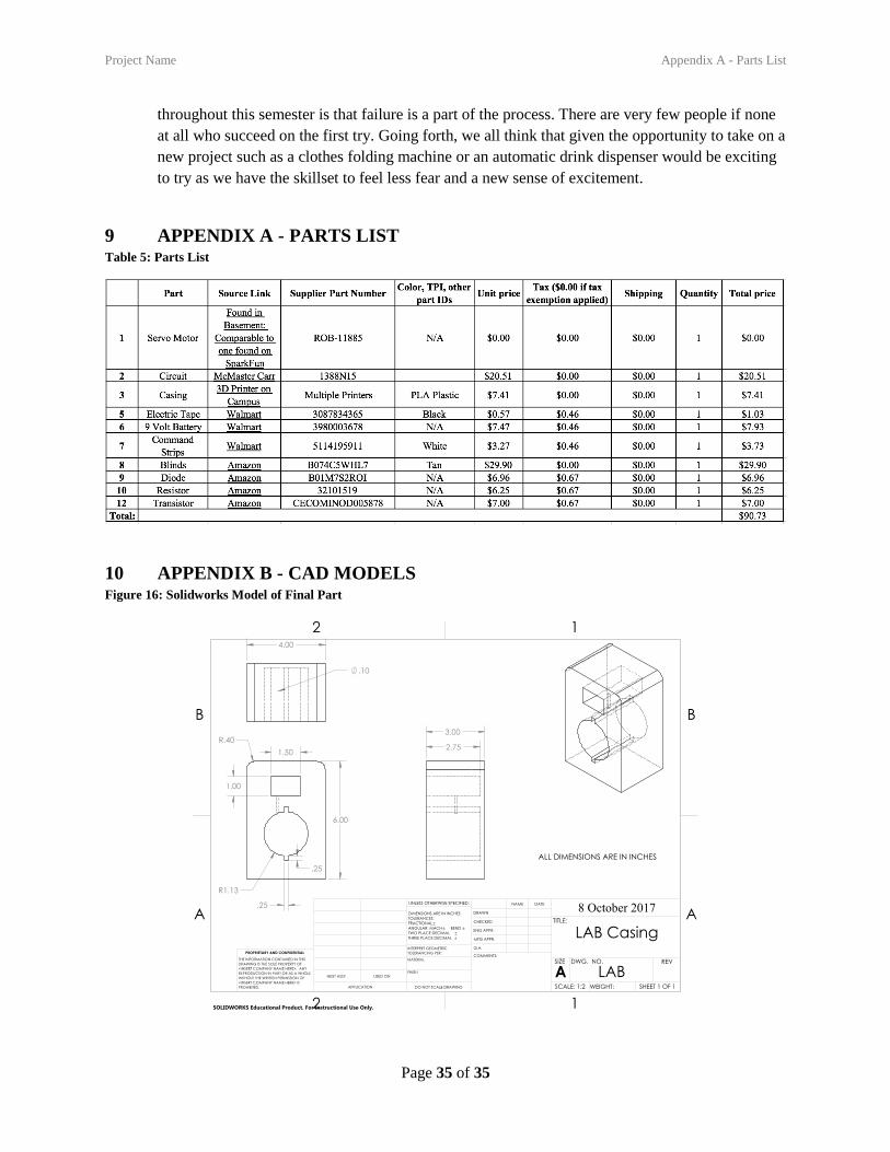
9 APPENDIX A - PARTS LIST Table 5: Parts List
10 APPENDIX B - CAD MODELS Figure 16: Solidworks Model of Final Part
Related Documents