....Instruction manual LIFT INVERTER Lift vector AC Drives AGL50

Welcome message from author
This document is posted to help you gain knowledge. Please leave a comment to let me know what you think about it! Share it to your friends and learn new things together.
Transcript

....Instruction manual
LIFT
INVE
RTE
R
Lift vector AC Drives
AGL50

2 AGL50
Thank you for choosing this Gefran product.We will be glad to receive any possible information which could help us improving this manual. The e-mail address is the following: [email protected] using the product, read the safety instruction section carefully.Keep the manual in a safe place and available to engineering and installation personnel during the product functioning period.Gefran S.p.A has the right to modify products, data and dimensions without notice.The data can only be used for the product description and they can not be understood as legally stated properties.This manual is updated according to firmware version V03.05.XX.All rights reserved.

AGL50 3
Table of Contents
Safety Symbol Legend ....................................................................................................................41 - Safety Precautions .....................................................................................................................4
1.1 Discharge time of the DC-Link .............................................................................................................................................6
2 - Introduction ................................................................................................................................63 - Environment ...............................................................................................................................7
3.1 Environmental Conditions ....................................................................................................................................................73.2 Storage and transport ..........................................................................................................................................................73.3 Standard ...............................................................................................................................................................................73.4 Input .....................................................................................................................................................................................83.5 AC Output .............................................................................................................................................................................93.6 Open-Loop and Closed-Loop control section .....................................................................................................................103.7 Accuracy .............................................................................................................................................................................103.8 Dimensions and installation guidelines ..............................................................................................................................11
4 - Wiring Procedure .....................................................................................................................134.1 Power Section ....................................................................................................................................................................134.2 EMC compliant electrical cabinet wiring rules ....................................................................................................................154.3 Cooling fans .......................................................................................................................................................................164.4 Regulation Section .............................................................................................................................................................174.5 RS 485 Serial Interface ......................................................................................................................................................184.5.1 RS485 serial terminals ........................................................................................................................................................................184.5.2 Serial protocol .....................................................................................................................................................................................184.6 Encoder Input .....................................................................................................................................................................19
5 - Drive Keypad Operation ..........................................................................................................205.1 Keypad ...............................................................................................................................................................................205.2 Moving through the drive main menu .................................................................................................................................215.3 Scrolling through the drive parameters ..............................................................................................................................225.4 Parameters modification ....................................................................................................................................................22
6 - Commissioning suggestions ..................................................................................................237 - Default lift configuration ..........................................................................................................24
7.1 Command Logic .................................................................................................................................................................247.2 Lift Sequence .....................................................................................................................................................................287.2.1 Lift-dedicated digital output functions ..................................................................................................................................................297.2.2 Speed indication..................................................................................................................................................................................307.3 Ramp Function ...................................................................................................................................................................307.3.1 Space calculation and acceleration / deceleration ramps settings ......................................................................................................307.3.2 Short Floor Function............................................................................................................................................................................317.4 Startup Menu ......................................................................................................................................................................327.5 Menù Display .....................................................................................................................................................................36
8 - Troubleshooting .......................................................................................................................388.1 Drive Alarm Condition ........................................................................................................................................................388.2 Alarm Reset ........................................................................................................................................................................388.3 List of drive alarm events ...................................................................................................................................................39
9 - Parameter list............................................................................................................................40
4 AGL50
Safety Symbol LegendIndicates a procedure, condition, or statement that, if not strictly observed, could result in personal injury or death.
Indicates a procedure, condition, or statement that, if not strictly observed, could result in damage to or destruction of equipment.
Indicates a procedure, condition, or statement that should be strictly followed in order to optimize these applications.
Note! Indicates an essential or important procedure, condition, or statement.
Caution
1 - Safety PrecautionsAccording to the EEC standards the AGL50 and accessories must be used only after checking that the ma-chine has been produced using those safety devices required by the 89/392/EEC set of rules, as far as the machine industry is concerned. These standards do not apply in the Americas, but may need to be conside-red in equipment being shipped to Europe.Drive systems cause mechanical motion. It is the responsibility of the user to insure that any such motion does not result in an unsafe condition. Factory provided interlocks and operating limits should not be bypas-sed or modified.
Electrical Shock and Burn Hazard:When using instruments such as oscilloscopes to work on live equipment, the oscilloscope’s chassis should be grounded and a differential amplifier input should be used. Care should be used in the selection of probes and leads and in the adjustment of the oscilloscope so that accurate readings may be made. See instrument anufacturer’s instruction book for proper operation and adjustments to the instrument.
Fire and Explosion Hazard:Fires or explosions might result from mounting Drives in hazardous areas such as locations where flammable or combustible vapors or dusts are present. Drives should be installed away from hazardous areas, even if used with motors suitable for use in these locations.
Strain Hazard:Improper lifting practices can cause serious or fatal injury. Lift only with adequate equipment and trained personnel.Drives and motors must be ground connected according to the NEC.Replace all covers before applying power to the Drive. Failure to do so may result in death or serious injury.
Adjustable frequency drives are electrical apparatus for use in industrial installations. Parts of the Drives are energized during operation. The electrical installation and the opening of the device should therefore only be carried out by qualified personnel. Improper installation of motors or Drives may therefore cause the failure of the device as well as serious injury to persons or material damage. Drive is not equipped with motor over-speed protection logic other than that controlled by software. Follow the instructions given in this manual and observe the local and national safety regulations applicable.
Always connect the Drive to the protective ground (PE) via the marked connection terminals (PE2) and the housing (PE1). AGL50 Drives and AC Input filters have ground discharge currents greater than 3.5 mA. EN 50178 specifies that with discharge currents greater than 3.5 mA the protective conductor ground connection (PE1) must be fixed type and doubled for redundancy.
The drive may cause accidental motion in the event of a failure, even if it is disabled, unless it has been disconnected from the AC input feeder.
Never open the device or covers while the AC Input power supply is switched on. Minimum time to wait before working on the terminals or inside the device is listed in section 1.1.
Warning
Warning
Attention

AGL50 5
Do not connect power supply voltage that exceeds the standard specification voltage fluctuation permissible. If excessive voltage is applied to the Drive, damage to the internal components will result.
Do not operate the Drive without the ground wire connected. The motor chassis should be grounded to earth through a ground lead separate from all other equipment ground leads to prevent noise coupling.
The grounding connector shall be sized in accordance with the NEC or Canadian Electrical Code.The connection shall be made by a UL listed or CSA certified closed-loop terminal connector sized for the wire gauge involved. The connector is to be fixed using the crimp tool specified by the connector manufactu-rer.
Do not perform a megger test between the Drive terminals or on the control circuit terminals.
Because the ambient temperature greatly affects Drive life and reliability, do not install the Drive in any loca-tion that exceeds the allowable temperature.
If the Drive’s Fault Alarm is activated, consult the chapter 8. TROUBLESHOOTING of this instruction book, and after correcting the problem, resume operation. Do not reset the alarm automatically by external sequen-ce, etc.
Be sure to remove the desicant dryer packet(s) when unpacking the Drive. (If not removed these packets may become lodged in the fan or air passages and cause the Drive to overheat).
The Drive must be mounted on a wall that is constructed of heat resistant material. While the Drive is opera-ting, the temperature of the Drive’s cooling fins can rise to a temperature of 194° F (90°C).
Do not touch or damage any components when handling the device. The changing of the isolation gaps or the removing of the isolation and covers is not permissible.
Protect the device from impermissible environmental conditions (temperature, humidity, shock etc.)
No voltage should be connected to the output of the drive (terminals U2, V2 W2). The parallel connection of several drives via the outputs and the direct connection of the inputs and outputs (bypass) are not permissi-ble.
A capacitative load (e.g. Var compensation capacitors) should not be connected to the output of the drive (terminals U2, V2, W2).
The electrical commissioning should only be carried out by qualified personnel, who are also responsible for the provision of a suitable ground connection and a protected power supply feeder in accordance with the local and national regulations. The motor must be protected against overloads.
No dielectric tests should be carried out on parts of the drive. A suitable measuring instrument (internal resi-stance of at least 10 k/V) should be used for measuring the signal voltages.
In case of a three phase supply not symmetrical to ground, an insulation loss of one of the devices connec-ted to the same network can cause functional problem to the drive, if the use of a delta/wye transformer is avoided (see par. 3.4).
Note! If the Drives have been stored for longer than two years, the operation of the DC link capacitors may be impaired and must be “reformed”.Before commissioning devices that have been stored for long periods, connect them to a power supply for two hours with no load connected in order to regenerate the capacitors, (the input voltage has to be applied without enabling the drive).
Note! The terms “Inverter”, “Controller” and “Drive” are sometimes used interchangably throughout the industry. We will use the term “Drive” in this document.
Warning
Caution

6 AGL50
1.1 Discharge time of the DC-LinkType In Time (seconds)2040 10.1 3002055 13 3002075 17.7 300
Tabella 1.1 DC Link Discharge Times
This is the minimum time that must be elapsed since a Drive is disconnected from the AC Input before an operator may service parts inside the Drive to avoid electric shock hazard.
Condition: These values consider a turn off for a Drive supplied at 480Vac +10%, without any option, ( the chargefor the switching supply is the regulation card, the keypad and the 24Vdc fans “if mounted”).The Drive is disabled. This represents the worst case condition.
2 - IntroductionAGL50 is a series of dedicated drives used to control lift asynchronous motors ranging from 4 to 7.5 kW. Thanks to the special lift application software, it is best used in case of plant modernization and, in general, in all open loop applications up to 1 m/s.The easy and adaptable programming procedure can be managed via the alphanumeric keyboard or via the PC configu-rator and it allows the drive fast commissioning.
Available options on demand:
- External EMC input filters- External Input / Output chokes- External braking resistors (connected between terminals C and BR1)
AGL50 7
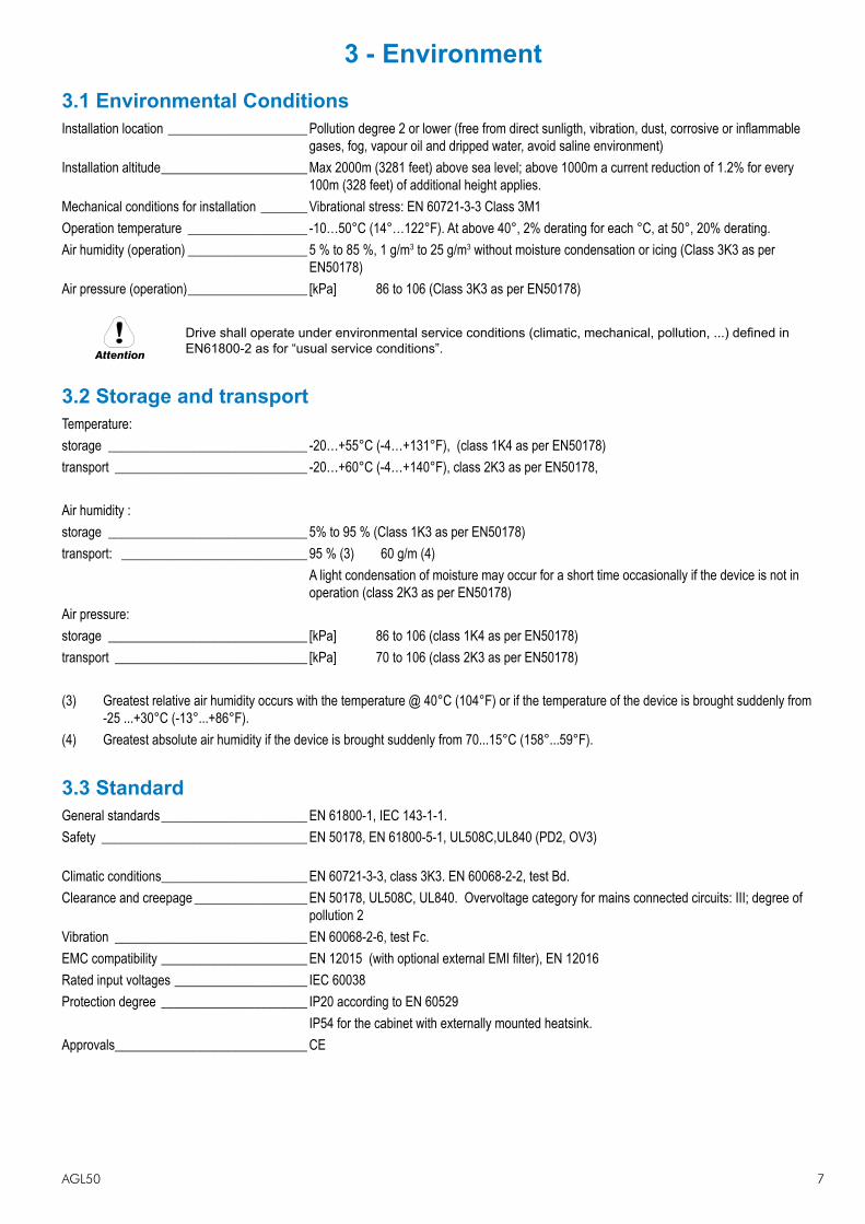
3 - Environment3.1 Environmental ConditionsInstallation location ��������������������� Pollution degree 2 or lower (free from direct sunligth, vibration, dust, corrosive or inflammable
gases, fog, vapour oil and dripped water, avoid saline environment)Installation altitude ���������������������� Max 2000m (3281 feet) above sea level; above 1000m a current reduction of 1.2% for every
100m (328 feet) of additional height applies.Mechanical conditions for installation ������� Vibrational stress: EN 60721-3-3 Class 3M1Operation temperature ������������������ -10…50°C (14°…122°F). At above 40°, 2% derating for each °C, at 50°, 20% derating.Air humidity (operation) ������������������ 5 % to 85 %, 1 g/m3 to 25 g/m3 without moisture condensation or icing (Class 3K3 as per
EN50178)Air pressure (operation) ������������������ [kPa] 86 to 106 (Class 3K3 as per EN50178)
Attention
Drive shall operate under environmental service conditions (climatic, mechanical, pollution, ...) defined in EN61800-2 as for “usual service conditions”.
3.2 Storage and transportTemperature:storage ������������������������������ -20…+55°C (-4…+131°F), (class 1K4 as per EN50178) transport ����������������������������� -20…+60°C (-4…+140°F), class 2K3 as per EN50178,
Air humidity :storage ������������������������������ 5% to 95 % (Class 1K3 as per EN50178)transport: ���������������������������� 95 % (3) 60 g/m (4) A light condensation of moisture may occur for a short time occasionally if the device is not in
operation (class 2K3 as per EN50178)Air pressure:storage ������������������������������ [kPa] 86 to 106 (class 1K4 as per EN50178)transport ����������������������������� [kPa] 70 to 106 (class 2K3 as per EN50178)
(3) Greatest relative air humidity occurs with the temperature @ 40°C (104°F) or if the temperature of the device is brought suddenly from -25 ...+30°C (-13°...+86°F).
(4) Greatest absolute air humidity if the device is brought suddenly from 70...15°C (158°...59°F).
3.3 StandardGeneral standards ���������������������� EN 61800-1, IEC 143-1-1. Safety ������������������������������� EN 50178, EN 61800-5-1, UL508C,UL840 (PD2, OV3)
Climatic conditions ���������������������� EN 60721-3-3, class 3K3. EN 60068-2-2, test Bd. Clearance and creepage ����������������� EN 50178, UL508C, UL840. Overvoltage category for mains connected circuits: III; degree of
pollution 2Vibration ����������������������������� EN 60068-2-6, test Fc. EMC compatibility ���������������������� EN 12015 (with optional external EMI filter), EN 12016Rated input voltages �������������������� IEC 60038 Protection degree ���������������������� IP20 according to EN 60529 IP54 for the cabinet with externally mounted heatsink. Approvals ����������������������������� CE

8 AGL50
3.4 Input
Type 2040 2055 2075Uln AC Input voltage [V] 3 x 380 V (-15%) ... 3 x 480 V (+10%)Power supply system TT,TNMaximum line voltage unbalance [%] 3 %AC Input frequency [Hz] 50 Hz – 2 % ... 60 Hz + 2 %THD of input current [%] > 100 % (without choke)In AC Input current for continuous service ::- Connection with 3-phase reactor
@ 400Vac; IEC 146 class 1 [A] 9 13 16@ 480Vac; IEC 146 class 1 [A] 8.2 11.7 14.3
- Connection without 3-phase reactor @ 400Vac; IEC 146 class 1 [A] 11 14 19@ 480Vac; IEC 146 class 1 [A] 10 12.6 17
Max short circuit power without line reactor (Zmin=1%) [kVA] 500 650 850Overvoltage threshold (Overvoltage) [V] 800Vdc
Undervoltage threshold (Undervoltage) [V] 380 Vdc (for 380,400Vac mains), 405 Vdc (for 420,440Vac mains), 415 Vdc (for 460,480Vac mains)
Braking IGBT Unit Standard internal (with external resistor); Braking torque 150%.
Power Supply and Grounding1) Drives are designed to be powered from standard three phase lines that are electrically symmetrical with respect
to ground (TN or TT network).2) In case of supply with IT network, the use of delta/wye transformer is mandatory, with a secondary three phase
wiring referred to ground.
Caution
In case of a three phase supply not symmetrical to ground, an insulation loss of one of the devices connec-ted to the same network can cause functional problem to the drive, if the use of a delta/wye transformer is avoided.
Please refer to the following connection sample.
Safetyground
L1
L2
L3
Earth
U1
/L1
V1
/L2
W1
/L3
U2
/T1
V2
/T2
W2
/T3
PE
2/
All wires (including motor ground) mustbe connected inside the motor terminal box
AC
OU
TP
UT
CH
OK
E
AC
Main
Supply
AC
INP
UT
CH
OK
E
PE
1/
Mains connection and inverter outputThe drivea must be connected to an AC mains supply capable of delivering a symmetrical short circuit current lower or equal to the values indicated on table. For the use of an AC input choke see chapter 4.
Note from the table the allowable mains voltages. The cycle direction of the phases is free.Voltages lower than the min. tolerance values can cause the block of the inverter.
Adjustable Frequency Drives and AC Input filters have ground discharge currents greater than 3.5 mA. EN 50178 specifies that with discharge currents greater than 3.5 mA the protective conductor ground connection (PE1) must be fixed type.

AGL50 9
AC Input Current
Note! The Input current of the Drive depends on the operating state of the connected motor. The tables (chapter 3.4) shows the values corresponding to rated continuous service, keeping into account typical output power factor for each size.
3.5 AC OutputType 2040 2055 2075
Pn mot (recommended motor output):@ Uln=400Vac; fsw=default [kW] 4 5.5 7.5@ Uln=460Vac; fsw=default [Hp] 5 7.5 10
U2 Max output voltage [V] 0.98 x Uln (AC Input voltage)f2 Max output frequency [Hz] 500 Hz (V/f)In Rated output current::
@ Uln=400Vac; fsw=default [A] 10.1 13 17.7@ Uln=480Vac; fsw=default [A] 8.6 11.7 14.9
Switching frequency fsw (Default) (5) [kHz] 8Switching frequency fsw (higher) (5) [kHz] 10,12Iovld [A] Short term overload current. 170% of In for 10s on 100s.Derating factor
Kv (1) 0.87Kt (2) 0.8Kf (3) 0.85; 0.7
Kalt (4) 1.2Braking unit intervention threshold (@ 400 V - 480 V) [Vdc] ON = 780 Vdc, OFF= 770 Vdc
(1): Derating factor for mains voltage at 460 Vac(2): Derating factor for 50°C ambient temperature (2 % each °C > 40 °C)(3): Derating factor for higher switching frequency(4): Derating factor for installation at altitudes above 1000 meters a.s.l.. Value to be applied at each 100 m increase
above 1000 m(5) It is possible to set a fixed switching frequency (from 4 to 12 kHz depending on size and with derating where applicable).
Otherwise it is possible to set a variable switching frequency between two levels (hswf and Iswf) defined according to size, heat sink temperature and stator frequency:
Type Higher sw frequency[kHz]
Lower sw frequency[kHz]
F out [Hz]
T [°C]
2040 8 4 3 642055 8 4 3 602075 8 4 3 60
The output of the Drive is ground fault and phase to phase output short protected.
Nota! The connection of an external voltage to the output terminals of the Drive is not permissible! It is allowed to disconnect the motor from the Drive output, after the Drive has been disabled.
The rated value of direct current output ( Icont ) depends on the ambient temperature ( KT ) and the switching frequency ( Kf) if higher than the default setting:
Icont = In x Kt x Kf
10 AGL50
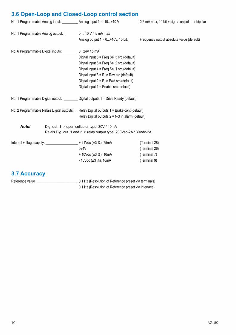
3.6 Open-Loop and Closed-Loop control sectionNo. 1 Programmable Analog input: ��������� Analog input 1 = -10...+10 V 0.5 mA max, 10 bit + sign / unipolar or bipolar
No. 1 Programmable Analog output: ������� 0 ... 10 V / 5 mA max Analog output 1 = 0...+10V, 10 bit, Frequency output absolute value (default)
No. 6 Programmable Digital inputs: �������� 0...24V / 5 mA Digital input 6 = Freq Sel 3 src (default) Digital input 5 = Freq Sel 2 src (default) Digital input 4 = Freq Sel 1 src (default) Digital input 3 = Run Rev src (default) Digital input 2 = Run Fwd src (default) Digital input 1 = Enable src (default)
No. 1 Programmable Digital output: �������� Digital outputs 1 = Drive Ready (default) No. 2 Programmable Relais Digital outputs: �� Relay Digital outputs 1 = Brake cont (default) Relay Digital outputs 2 = Not in alarm (default)
Note! Dig. out. 1 > open collector type: 30V / 40mARelais Dig. out. 1 and 2 > relay output type: 230Vac-2A / 30Vdc-2A
Internal voltage supply: ������������������ + 21Vdc (±3 %), 75mA (Terminal 28) 024V (Terminal 26) + 10Vdc (±3 %), 10mA (Terminal 7) - 10Vdc (±3 %), 10mA (Terminal 9)
3.7 AccuracyReference value ����������������������� 0.1 Hz (Resolution of Reference preset via terminals) 0.1 Hz (Resolution of Reference preset via interface)
AGL50 11
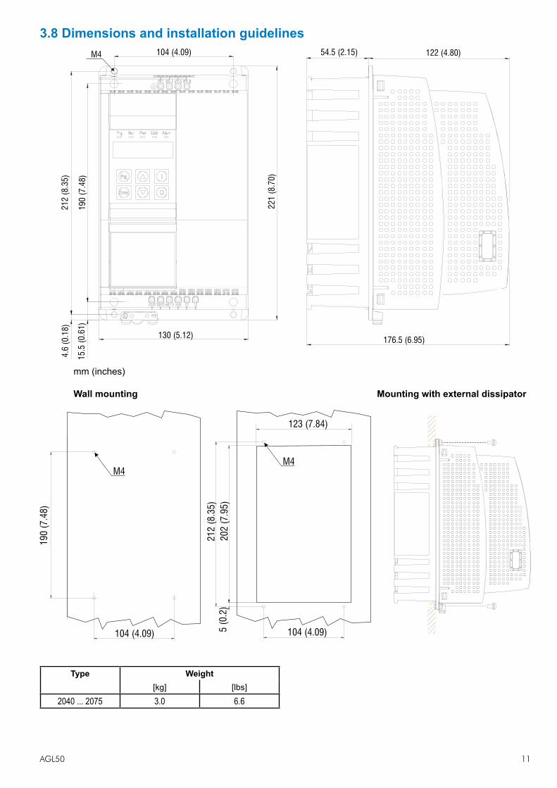
3.8 Dimensions and installation guidelines104 (4.09)
21
2(8
.35
)
19
0(7
.48
)
4.6
(0.1
8)
15
.5(0
.61
)
130 (5.12)
22
1(8
.70
)
176.5 (6.95)
122 (4.80)M4 54.5 (2.15)
mm (inches)
Wall mounting Mounting with external dissipator
21
2(8
.35
)
104 (4.09)
20
2(7
.95
)
19
0(7
.48
)
104 (4.09)5(0
.2)
M4
123 (7.84)
M4
Type Weight[kg] [lbs]
2040 ... 2075 3.0 6.6

12 AGL50
Mounting ClearanceThe Drives must be mounted in such a way that the free flow of air is ensured. The clearance to the device must be at least 150 mm (6 inches). A space of at least 50 mm (2 inches) must be ensured at the front.Maximum angle of inclination: 30° with respect to the vertical axis.Devices that generate a large amount of heat must not be mounted in the direct vicinity of the frequency inverter.Fastening screws should be re-tightened after a few days of operation.
10mm0.39( )
150 mm (6)
50 mm (1.97)20 mm(0.79)
150 mm (6)
�
� � �
�
10mm(0.39)
�

AGL50 13
4 - Wiring Procedure4.1 Power SectionU1/L1, V1/L2, W1/L3 AC mains voltage (3 x 380 V (-15%) ... 3 x 480 V (+10%)PE1 Mains ground connection (on terminal)BR1 Braking unit resistor command (braking resistor must be connected between BR1 and C)C, D Intermediate circuit connectionU2/T1, V2/T2, W2/T3 Motor connectionPE2 Motor ground connection (on chassis)
Maximum cable cross-section Recommendedstripping
Tighteningtorque (min)
(mm2) (AWG) (mm) (Nm)2040 - 2055 - 2075 4 (rigid) / 2.5 (flexible) 12 8 0.5…0.6
Note! Use 60°C / 75°C copper conductor only.
External fuses of the power section
The inverter must be fused on the AC Input side. Use fast-acting fuses only. Use the fuses shown in the table below.
Connections with three-phase inductance on AC input will improve the DC link capacitors life time.
SizesDC link capacitor hours
of service life [h]Europa America
Type Code Type Code2040 10000 GRD2/20 F4D15 A70P20 S7G482055 10000 GRD2/25 F4D16 A70P30 S7I502075 10000 GRD2/25 F4D16 A70P30 S7I50
External fuses of the Power Section DC input side
Use fast-acting fuses only. Use the fuses shown in the table below.
SizesEuropa America
Type Code Type Code2040 GRD2/20 F4D15 A70P20 S7G482055 GRD2/25 F4D16 A70P30 S7I502075 GRD2/25 F4D16 A70P30 S7I50
Fuse manufacturers: Type GRD... , Z14... 14 x 51 mm Jean Müller, Eltville A70... Ferraz FWP... Bussmann
Input chokes
The three-phase mains choke is strongly recommended in order to:- limit the RMS input current of the AGL50 inverter.- increase the life of intermediate circuit capacitors and reliability of input diodes.- reduce the harmonic distortion of the current absorbed by the grid to typical values of 70% (with rated current)
Sizes THD In @ 400 V [A] Type Code2040
< 70 %9 LR3y-2040 S7AAG
2055 13 LR3y-2055 S7AB52075 16 LR3y-2075 S7AB6

14 AGL50
Use the following AC chokes to reduce the line current THD even more (< 35%).
Sizes THD In @ 400 V [A] Type Code2040
< 35%8 LR3y-2040-35% S7HB1
2055 12 LR3y-2055-35% S7HB22075 15 LR3y-2075-35% S7FO9
Output chokes
Output chokes are used to reduce the effects of the dv/dt of the power modules (IGBT). Voltage fronts can damage the electrical insulation of the motors or, if the motor cables are long (typically more than 100 m in length) or highly capaci-tive, they can cause drive malfunctions and the repeated generation of overcurrent (OC) or desaturation (OCH) alarms. The output chokes are listed in the table below:
SizesMains
inductance [mH]
Ratedcurrent
[A]
Saturationcurrent
[A]Type Code
2040 0.87 10.1 20 LU3-QX02 S7FL32055 0.87 16 34 LU3-005 S7FG32075 0.51 27 57 LU3-011 S7FG4
Internal braking unit
Internal braking units with external braking resistors (wired between terminals C and BR1) are used to prevent dangerous DC link voltage levels in case of braking. Technical data of the internal braking unit (50% duty cycle)
Sizes Rated current [Arms]
Peak current[Apeak]
Minimum braking R value[Ohm]
2040 5.7 8 1002055 8.5 12 672075 8.5 12 67
Braking Resistors
Warning
The braking resistors can be subject to unforeseen overloads due to possible failures.The resistors have to be protected using thermal protection devices. Such devices do not have to interrupt the circuit where the resistor is inserted but their auxiliary contact must interrupt the power supply of the drive power section. In case the resistor foresees the precence of a protection contact, such contact has to be used together with the one belonging to the thermal protection device.
Recommended resistors for use with internal braking unit:
Sizes Resistor type CodeMax Overload
energy, 1”- duty-cycle 10%
Max Overloadenergy, 30”- duty-
cycle 25%[kJ]
Pn cont (*)[W]
Rbr
[Ohm]
2040 RF 200 100R S8SA15 1.5 4 200 1002055 RF 200 68R S8SA14 1.5 4 200 682075 RF 400 68R S8SA16 3.5 10 400 68
Resistors protection degree: IP44.The braking resistor is optional and has always to be mounted externally.(*) rated power with continuous operation. Without heat sink. If the resistors are mounted on unpainted radiation plates (thermal resistance shown) the power ratings are those shown in the table below. In overload conditions, heavier duty cycles can be set proportional to the power ratings.

AGL50 15
Sizes Radiator Therm. Res. ( °C/W )
P Cont. serv. ( W )
RF 200 100R 0.75 400RF 200 68R 0.55 550RF 400 68R 0.4 750
Optional EMC filters
An external EMI filter can be used to meet the requirements of EN 12015.
Sizes Filter type Code EN61800-3(Motor cable length)
2040 EMI-FTF-480-7 S7GHL 5 m2055 EMI-FTF-480-16 S7GHO 5 m2075 EMI-FTF-480-16 S7GHO 5 m
4.2 EMC compliant electrical cabinet wiring rulesPanels and cabinetsMounting panel and cabinet (including the doors) have to be grounded, with a direct connection to the ground bus, using strapwire.
Removal of the paint from the support areasThe paint should be removed from the choke, mounting panel and chassis support areas.
Caution
The anodized aluminium does not conduct.
Ground terminals of the inverterThe inverters are provided with two ground terminals: one must be connected to the ground bus and the other to the filter.
Ground terminal of the chokeThe earth terminal of the choke must be connected to the ground bus.
Shielding of cables for analog signalsAnalog signals must be shielded (each signal must be contained in the screen united with the zero volt), the same is true for the constant references (E.g.. 10V). The shield must be grounded at 360° using the omega connectors available on the support panel of the regulation board. This is in front of the terminals strip on the bar above the board.
Note! Cable shields should be grounded at one end only.
Min. distance between signal and power cablesThe minimum distance between parallel signals and power cables is 30cm (12 inches). Possible crossings have to be made at 90°. In case of double cabinets (entry to the insde of the cabinet on both sides with 2 different panels installed) it is advisable to have all signals cables conveyed into troughs mounted on the inverter side (front) and to pass motor cables on the other side (back) trough. In case of single cabinets, it is advisable to let the power cable run vertically, while signal cables run horizontally, keeping the maximum possible distance.
Shielding of the supply for an AC motorThe AC motors have to be supplied through a four pole shielded cable (three phases plus a green/yellow ground wire), or through four unshielded cables, which are inserted inside a metal channel. It is important that a direct connection (four cables) between the panel grounding and the motor ground has been made and that the fourth cable had been inserted in a shield.
Ground connection to both sides of the cable shield (AC motor)The shield of the supply cable of the AC motors must be grounded on both sides in order to obtain 360° contact, that means the whole shield. This can be accomplished using suitable metallic EMC cables press grounded at a full 360° at the input of the cabinet and of the motor’s terminal strip. If this connection is not possible, the shielded cables should be brought inside the cabinet and connected with an omega connector to the mounting panel. The same must be done

16 AGL50
on the motor side. In case a 360° connection on the motor’s terminal strip is not possible, the shield must be grounded before entering into the terminal strip. This should be done on the metal support of the motor, using an omega connector (see figure). In case a metal duct has to be used, it should be grounded at a full 360° where possible.
Pigtail avoidenceWhile grounding the shieldes of the cables, one has to use a 360° connection (E.g.: omega bus as in the figure 4.2) with a pigtail connection to be absolutely avoided. By pigtail is meant the connection to earth ground of the cable shield by means of an additional wire.
Direct connection between the ground bus and motor chassisIndependently from ground-connection of the motor’s chassis, it must always be connected to the ground wire (yellow/green) coming from the panel ground bus.
Max length of the AC motor’s cables inside the cabinetFrom the grounding of the screen side cabinet of the inverter terminal strip, the supply’s cables have to measure 5 meters (16.4 feet) maximum.
Mounting sequence for EMI-... filters with inverterIn case of inverters, these filters have to be serie-connected between the inverter and the AC mains. The connection between the filter and inverter’s terminals must be done with a four poles cable, whose max.length is 30 cm. (12 inches). If that connection is longer, the cable must be shielded.Grounding of EMI-... filters with inverterThe yellow/green ground wire of the four poles cable must be connected on one side directly to one of the two gounding terminals of the inverter, the other side to one of the two filters grounding terminals. The other grounding terminal of the filter must be brought directly to the grounding bus of the cabinet.
Schermo/Shield
Connettore OmegaOmega connector
Area non verniciataNot painted area
Pannello di fissaggioMounting panel
Figura 4.2.OMEGA plug: grounding 360° of a shielded cable.
4.3 Cooling fansNo connection is required, the internal fans are power supplied by an internal circuit.
Sizes Heat dissipation) Fan capacity
[W]Heat sink
[m3/h]Internal [m3/h]
2040 180 20 -2055 205 2 x 20 -2075 280 2 x 20 11

AGL50 17
4.4 Regulation Section
Strip1
Strip2
242 4 6 8 10 12 14 16 18 20 22 2826
231 3 5 7 9 11 13 15 17 19 21 2725
S T R I P 1
Term. Designation Function (Signal level MAX)1/3 n.a.5 Analog output 1 VOLTAGE programmable analog output (0...10V) Default : I.300 = [0] Freq out abs (0...10V / 5mA)7 + 10V OUT + 10 Vdc potential voltage reference Default : n.a. (+10Vdc / 5mA, max 10mA)9 - 10V OUT - 10 Vdc potential voltage reference Default : n.a. (-10Vdc / 5mA, max 10mA)11 Digital output 1+ Programmable digital output (Optomos) Default : I100 = [51] Contactor (+30V / 40mA)13 Digital output 1- Programmable OPEN COLLECTOR digital output (negative terminal) 15 RS485 Link+ Link+ (RxA / TxA) signal of RS 485 serial line17 RS485 Link- Link- (RxB / TxB) signal of RS 485 serial line 19 RS 485 eq. ref. Equipotential reference of RS 485 serial line 21 COM Relay 1 Common contact RELAY 1 digital output (250Vac / 2A, 30Vdc / 2A)23 Digital output 1 Programmable RELAY digital output, NO contact (250Vac / 2A, 30Vdc / 2A) Default : I101 = [54] Brake cont 25 COM Relay 2 Common contact RELAY 2 digital output (250Vac / 2A, 30Vdc / 2A)17 Digital output 2 Programmable RELAY digital output, NO contact (250Vac / 2A, 30Vdc / 2A) Default : I102 = [02] No alarms S T R I P 2
Term. Designation Function (Signal level MAX)2/4 n.a.6 COM analog. In/Out Potential reference of analog inputs/outputs -8 Analog input 1 Programmable VOLTAGE analog input Default : I.200 = [1] -10...+10V (±10V / 0.5mA)10 0 V 24 0 V 24 potential reference Programmable digital inputs (24Vdc/ 5mA, 12...30Vdc max)12 Digital input 1 Default : I.000 = Enable src 14 Digital input 2 Default : I.001 = Run Fwd src16 Digital input 3 Default : I.002 = Run Rev src18 Digital input 4 Default : I.003 = Freq sel 1 src20 Digital input 5 Default : I.004 = Freq sel 2 src22 Digital input 6 Default : I.005 = Freq sel 3 src24 COM Digital inputs 0 potential reference of digital inputs26 0 V 24 0 V 24 potential reference28 + 24V OUT + 24 Vdc potential voltage reference (+21Vdc / 75mA)
n.a. = not assigned
AGL50 18
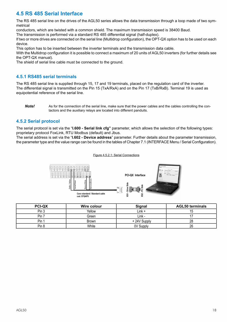
4.5 RS 485 Serial InterfaceThe RS 485 serial line on the drives of the AGL50 series allows the data transmission through a loop made of two sym-metricalconductors, which are twisted with a common shield. The maximum transmission speed is 38400 Baud.The transmission is performed via a standard RS 485 differential signal (half-duplex).If two or more drives are connected on the serial line (Multidrop configuration), the OPT-QX option has to be used on eachdevice.This option has to be inserted between the inverter terminals and the transmission data cable.With the Multidrop configuration it is possible to connect a maximum of 20 units of AGL50 inverters (for further details seethe OPT-QX manual).The shield of serial line cable must be connected to the ground.
4.5.1 RS485 serial terminalsThe RS 485 serial line is supplied through 15, 17 and 19 terminals, placed on the regulation card of the inverter.The differential signal is transmitted on the Pin 15 (TxA/RxA) and on the Pin 17 (TxB/RxB). Terminal 19 is used asequipotential reference of the serial line.
Note! As for the connection of the serial line, make sure that the power cables and the cables controlling the con-tactors and the auxiliary relays are located into different panduits.
4.5.2 Serial protocolThe serial protocol is set via the “I.600 - Serial link cfg” parameter, which allows the selection of the following types:proprietary protocol FoxLink, RTU Modbus (default) and Jbus.The serial address is set via the “I.602 - Device address” parameter. Further details about the parameter transmission,the parameter type and the value range can be found in the tables of Chapter 7.1 (INTERFACE Menu / Serial Configuration).
Figure 4.5.2.1: Serial Connections
XS
1 -
Dri
ve S
ide
XS
2 -
PC
Sid
e
Gia
llo /
Yello
w
1 235 7 9 11 15 17 19 213
2 246 8 10 12 14 16 18 284
Cavo standard / Standard cable
cod. S7QAF9
Verd
e/G
reen
Bia
nco/W
hite
Marr
one/B
row
n
PCI-QX Interface
13 2725
262220
PCI-QX Wire colour Signal AGL50 terminalsPin 3 Yellow Link + 15Pin 7 Green Link - 17Pin 1 Brown + 24V Supply 28Pin 8 White 0V Supply 26

AGL50 19
4.6 Encoder InputFigure 4.6.1: encoder connection
U2/T1
V2/T2
W2/T3
M
PE2
EDigital Input 5
Digital Input 6
20
22
Channel A
Channel B
Externalpower supply
+24V
024V
COM 24
Table 4.6.1: Recommended Cable Section and Length for the Connection of Encoders
Cable section [mm2] 0.22 0.5 0.75 1 1.5Max Length. m [feet] 27 [88] 62 [203] 93 [305] 125 [410] 150 [492]
Requirements:
Digital encoder:
• max frequency: 25 kHz (select the appropriate number of pulses depending on required max. speed)
• Channels :
- one-channel: A (one-channel complementary A-,NOT allowed)
- two-channel: A and B (two-channel complementary A- and B-, NOT allowed).
Encoder loss detection is not possible.
• Power supply: + 24V externally supplied.
• The digital inputs common (terminal 24) have to be rightly connected to the external supply:
- to 0 V of supplier, if the encoder is PNP type
- to + 24 V of supplier, if the encoder is NPN type.
Note! If Digital input 5 and Digital input 6 are used as encoder input, I.004 and I.005 must be set to [0] None.Than encoder feedback parametrizzation must be execute.

20 AGL50
5 - Drive Keypad OperationIn this chapter the parameters management is described, by using the drive keypad.
5.1 Keypad
Caution
Changes made to parameter have immediate effect on drive operation, but are not automatically stored in permanent memory. An explicit command is required to permanently store the parameters: “C.000 Save parameters”.
Rev Fwd Limit AlarmPrg
Prg
Enter
Codice parametro
(Menu + numero da 000 a 999)
Menu:
d
S
I
=DISPLAY
=STARTUP
=INTERFACE
F
P
A
C
=FREQ & RAMPS
=PARAMETER
=APPLICATION
=COMMAND
Limit AlarmPrg Rev Fwd
Prg Scroll menù: Allows navigation thruogh the drive main menu (d.xxx, S.xxx, I.xxx, F.xxx, P.xxx, A.xxx and C.xxx). Also used to exit the editing mode of a parameter without appling the changes.
E Enter key: Used to enter the editing mode of the selected parameter or to confirm the value.▲ UP key: Used to scroll up through parameters or to increase numeric values while in editing mode; it can
also be used to increase motorpotentiometer reference value, when F.000 Motorpot ref parameter is displayed (F, FREQ RAMP menu).
▼ DOWN key: Used to scroll down through parameters or to decrease numeric values while in editing mode; it can also be used to decrease motorpotentiometer reference values, when F.000 Motorpot ref parameter is displayed (F, FREQ RAMP menu).
I Start key: Used to START the drive via keypad; requirements: +24V between 12 & 26 terminals (Enable) +24 V between 14 & 26 terminals (Run Fwd) or + 24 V between 16 & 26 terminals (Run Rev) P.000 Cmd source sel = [1] CtlWrd & kpd parameter settingO Stop key: Used to STOP the drive via keypad;
Keypad LED’s meaning:PRG (Yellow Led) Flashes if the parameters have not been permanently saved to memory.REV (Green Led) Reverse runningFWD (Green Led) Clockwise motor rotationLimit (Yellow Led) Inverter limit stateAlarm (Red Led) Inverter alarm state
Note! The FWD LED lights up during the direct current injection phase (start and stop).

AGL50 21
5.2 Moving through the drive main menuSoon after, the keypad display will show d.000 Output frequency parameter of DISPLAY menu.
Prg
Prg
Prg
Prg
Prg
Prg
Prg
Prg
d.000
S.000
I.000
F.000
P.000
A.000
C.000
Menu of read-only parameters (display)
Menu of input/output drive settings(digital/analog)
Menu of multi frequencies and ramps settings
Menu of read/write drive parameters
Menu of PID function settings
Menu of control-type parameters(Save, Load default, etc.)
Menu of basic drive start up parameters
0.00
22 AGL50
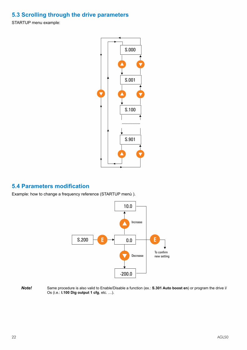
5.3 Scrolling through the drive parametersSTARTUP menu example:
----------------
S.000
S.001
S.100
S.901
5.4 Parameters modificationExample: how to change a frequency reference (STARTUP menù ).
E
Decrease
Increase
E
To confirm
new setting
S.200
10.0
0.0
-200.0
Note! Same procedure is also valid to Enable/Disable a function (ex.: S.301 Auto boost en) or program the drive I/Os (i.e.: I.100 Dig output 1 cfg, etc. …).

AGL50 23
6 - Commissioning suggestionsBefore changing the parameter settings make sure that the starting values are default values.Change the parameters one at the time; if the change on any parameter is not effective, restore the parame-ter initial value before changing another one.
• In order to avoid problems linked to running comfort, it is advisable to perform a preliminary control of the motor parameters.
Check in the STARTUP menu that the value set in the following parameters corresponds to the motor nameplate data:
S.100 Base voltage Inverter maximum output voltage (Vrms). S.101 Base frequency Motor base frequency (Hz). S.150 Motor rated curr Motor rated current (Arms). S.151 Motor pole pairs Number of motor polepairs. S.152 Motor power fact (cos phi) Motor input power factor with rated current and voltage.
• In order to avoid too high settings of the acceleration and deceleration values (jerk), make sure that the slowing-down distances correspond to those listed in the table:
Suggested slowing-down distances
Plant rated speed (m/s) 0,6 0,8 1,0Suggested slowing-down distance (mm) 800 1000 1300
Such distances grant a high running comfort with the factory set jerk values.
• The default speed levels can be selected on the terminal 18. It is advisable to use the frequencies as follows: S.200 Frequency ref 0 Slow speed: it is the floor reaching speed (frequency) S.201 Frequency ref 1 High speed: it is the rated speed (frequency) required by the motor for that specific plant.
Other speeds (maintenance, rephasing procedure etc.) can be selected as per table 7.2.
• In the open loop plants (without encoder), the boost can be increased if the lift car tends to rotate in the opposite direction during the starting phase or if it can not start in spite the running speed has been set (S.300 Manual boost, default = 3). The boost should be gradually increased by 1% at the time. Too high values cause the intervention of the current limit alarm.
24 AGL50
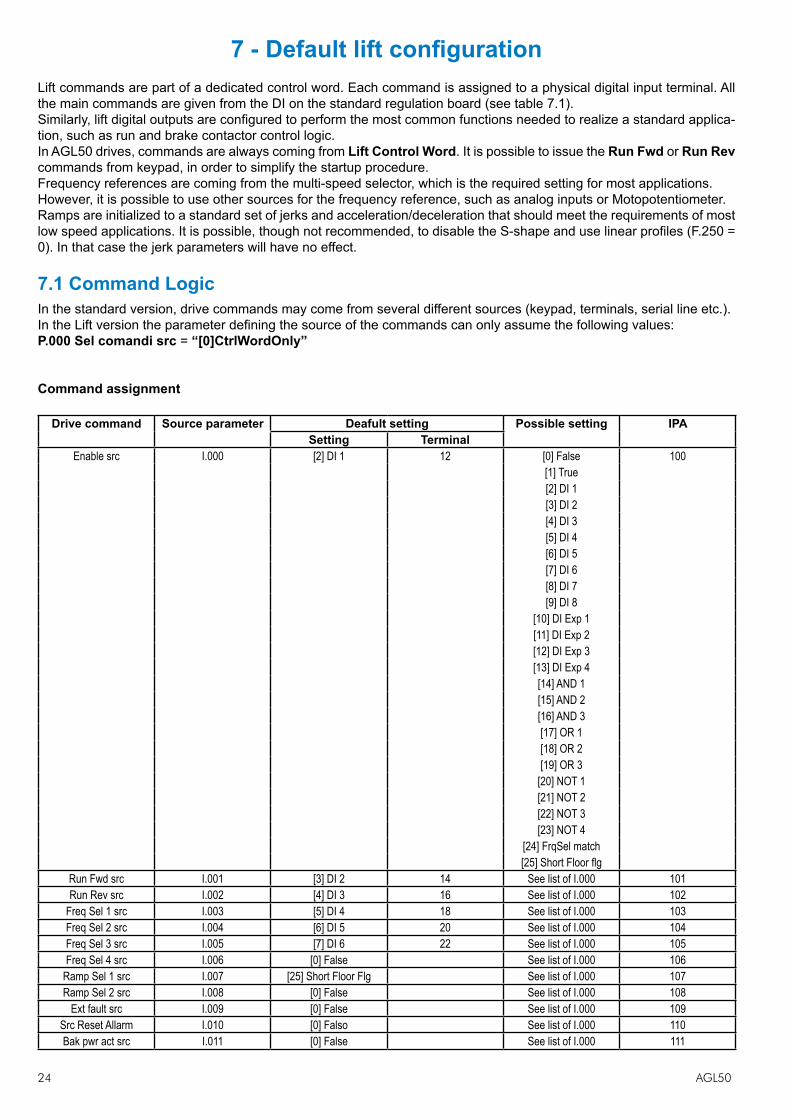
7 - Default lift configurationLift commands are part of a dedicated control word. Each command is assigned to a physical digital input terminal. All the main commands are given from the DI on the standard regulation board (see table 7.1).Similarly, lift digital outputs are configured to perform the most common functions needed to realize a standard applica-tion, such as run and brake contactor control logic.In AGL50 drives, commands are always coming from Lift Control Word. It is possible to issue the Run Fwd or Run Rev commands from keypad, in order to simplify the startup procedure.Frequency references are coming from the multi-speed selector, which is the required setting for most applications. However, it is possible to use other sources for the frequency reference, such as analog inputs or Motopotentiometer.Ramps are initialized to a standard set of jerks and acceleration/deceleration that should meet the requirements of most low speed applications. It is possible, though not recommended, to disable the S-shape and use linear profiles (F.250 = 0). In that case the jerk parameters will have no effect.
7.1 Command LogicIn the standard version, drive commands may come from several different sources (keypad, terminals, serial line etc.).In the Lift version the parameter defining the source of the commands can only assume the following values:P.000 Sel comandi src = “[0]CtrlWordOnly”
Command assignment
Drive command Source parameter Deafult setting Possible setting IPASetting Terminal
Enable src I.000 [2] DI 1 12 [0] False 100[1] True[2] DI 1[3] DI 2[4] DI 3[5] DI 4[6] DI 5[7] DI 6[8] DI 7[9] DI 8
[10] DI Exp 1[11] DI Exp 2[12] DI Exp 3[13] DI Exp 4[14] AND 1[15] AND 2[16] AND 3[17] OR 1[18] OR 2[19] OR 3
[20] NOT 1[21] NOT 2[22] NOT 3[23] NOT 4
[24] FrqSel match[25] Short Floor flg
Run Fwd src I.001 [3] DI 2 14 See list of I.000 101Run Rev src I.002 [4] DI 3 16 See list of I.000 102
Freq Sel 1 src I.003 [5] DI 4 18 See list of I.000 103Freq Sel 2 src I.004 [6] DI 5 20 See list of I.000 104Freq Sel 3 src I.005 [7] DI 6 22 See list of I.000 105Freq Sel 4 src I.006 [0] False See list of I.000 106
Ramp Sel 1 src I.007 [25] Short Floor Flg See list of I.000 107Ramp Sel 2 src I.008 [0] False See list of I.000 108
Ext fault src I.009 [0] False See list of I.000 109Src Reset Allarm I.010 [0] Falso See list of I.000 110Bak pwr act src I.011 [0] False See list of I.000 111

AGL50 25
Drive command Source parameter Deafult setting Possible setting IPASetting Terminal
Forced stop src I.012 [0] False See list of I.000 185Table 7.1 – Command assignment
Each command may come from any of the drive digital input terminals (either standard or expanded), or can be a logical combination of terminal inputs, obtained by using the drive internal programmable area
It is anyway possible to assign commands different from the default ones: For example, if we want the Enable command to come from the digital input 3 of the drive (terminal 16 on the regulation board), we have to set parameter I.000 Enable src to the value “[4] DI 3”.
Note: If the source of a command is specified as an expanded DI, and the I/O expansion board is not mounted, the command will always be inactive (FALSE).
A brief description of each command follows.
Enable src The Enable command must always be present, in order to activate the inverter output bridge. If the Enable input is not present, or the Enable signal is removed at any time during the Lift sequence, the output stage of the drive is disabled, and the Run contactor is open, regardless of the status of all the other inputs.
Run Fwd src (Upward command) Closing the input 14, the upward Lift sequence is started (see Figure 7.1).
Run Rev src (Downward command) Closing the input 16, the downward Lift sequence is started (see Figure 7.1).
Note: The direction of the motion can also be reversed by setting a negative frequency reference. With a negative frequency reference, the Run Fwd src command will cause a downward motion, while a Run Rev src com-mand will cause the cabin to move upward.
Note: The lifting sequence will not start if both Run Fwd src and Run Rev src commands are activated at the same time.
Freq Sel 1 ... 4 src (Selection of the speed reference) The binary code defined by the status of these signals selects the frequency reference (speed) for
the ramp generator (see Fig.7.2), according to the following table:
Freq Sel 4 Freq Sel 3 Freq Sel 2 Freq Sel 1 Code Active frequency referenceTerminal XX Terminal 22 Terminal 20 Terminal 18
0 0 0 0 0 S.200 Rif frequenza 00 0 0 1 1 S.201 Rif frequenza 10 0 1 0 2 S.202 Rif frequenza 20 0 1 1 3 S.203 Rif frequenza 30 1 0 0 4 S.204 Rif frequenza 40 1 0 1 5 S.205 Rif frequenza 50 1 1 0 6 S.206 Rif frequenza 60 1 1 1 7 S.207 Rif frequenza 71 0 0 0 8 F.108 Rif frequenza 81 0 0 1 9 F.109 Rif frequenza 91 0 1 0 10 F.110 Rif frequenza 101 0 1 1 11 F.111 Rif frequenza 111 1 0 0 12 F.112 Rif frequenza 121 1 0 1 13 F.113 Rif frequenza 131 1 1 0 14 F.114 Rif frequenza 141 1 1 1 15 F.115 Rif frequenza 15
(Emergency run freq)
Table 7.2 – Multi-frequencies selection

26 AGL50
Note: The last multi-frequency has also a special meaning when using the backup power supply. If the drive is being fed by the backup power supply, the frequency reference is clamped to the value defined by the para-meter F.115.If the backup power supply is not used, F.115 can be used as one of the multi-frequencies and is selected by setting to TRUE all the selectors (Freq Sel 1 to Freq Sel 4).
Ramp Sel 1 ... 2 The binary code defined by the status of these signals selects the set of parameters for ramp pro-file (jerks, acceleration and deceleration). By default, the first ramp selector is commanded by the ShortFloorFl (see chapter 7.3), while the second ramp selector is fixed to FALSE. Therefore, the first ramp set is normally active, and the drive will automatically switch to the second ramp set whenever a short floor is detected (see Fig.7.5).
External fault Activation of this command, will cause the drive to trip with an external fault alarm. If the alarm oc-curs while a lift sequence is in process, the sequence is immediately aborted and the Run contactor is open. In order to restore drive operation, an explicit Alarm Reset command is needed.
Fault reset src (Alarm reset) Activation of this command will restore drive operation after a trip.
Bak pwr act src This command tells to the drive that a backup power supply is being used. See chapter 9 for a de-tailed description.
In order to simplify the drive startup, it is possible to issue Run Fwd src or Run Rev src commands from the “I-O” keys of the drive keypad.
Typical example:
The user wants to execute tuning of the motor resistance, but does not want to issue the start sequence from the external PLC. In this case, it is possible to program the drive as follows:
- Set parameter P.000 Cmd source sel = “[1] CtlWrd & kpd”- Set parameter I.000 Enable src = “[1] True”- Set parameter I.001 RunFwd src = “[1] True”- Issue the command for tuning, by setting C.100 Measure stator R = [1]; the drive keypad will show the message
“tune”.- Press the “I” key; the keypad will show the message “run”, meaning that the tuning procedure is in progress. Wait
until the procedure ends, and the keypad will show the message “done”.
Nota: The motor output contacts must be closed during the tuning procedure, in order to allow current to flow into the motor. Either hard-wire the RUN contactor closed during tuning procedure, or connect the dedicated output of the drive to the RUN contactor.
- Once the tuning procedure is finished, restore the original settings for the parameters above, following the order:
I.001 Run Fwd src = “[3] DI 2” I.000 Enable src = “[2] DI 1” P.000 Cmd source sel = “[0] CtrlWordOnly”

AGL50 27
K1MK2MK3M
C
D
BR1
U1/L1
W1/L3
V1/L2
K1M
PE1
3 Ph
AC
mains
U2/T1
W2/T3
V2/T2
PE2
K2M K3M
L1F13 Ph
Motor
+
K3MK2M
-
FR
FR(R)L02L01
EnableSafety contacts
Run Fwd src
Run Rev src
Freq Sel 1 src
Regulation Board
Brake cont
Power Board
Brake
Brake cont
Braking resistor
12
14
16
18
20Src Sel Freq 2
22Src Sel Freq 3
28
25
27
RO 2
Motor not in Alarm
21
23
RO 1
DI 1
DI 2
DI 3
DI 4
DI 5
+24Vdc
DI 3
DI 6
11
13
DO 1 (NPN)
Contactor
+24V 28)(terminal
0V (terminal 26)Load
11
13
DO 1 (PNP)
+24V 28)(terminal
0V 26)(terminalLoad
Contactor
24
024V26
COM-DI
Fig.7.1 – Lift standard wiring
Note! The connections indicated for command inputs represent the most common solution for an PNP typecom-mand. Digital I/Os with internal supply.

28 AGL50
7.2 Lift SequenceTiming diagrams of the lift sequence are reported in Fig. 7.2 and Fig. 7.3.
I.000 Enable
I.001 Run Fwd
XOR
I.002 Run Rev
I.003 ... I.006Freq Sel 1...4 1 0
D.007 Actualspeed
(Motor speed)
D.002 Outputcurrent
(Inverter)
[51] Runcontactor(*)
[45] DC-braking(Motor)
(*)
[55] Liftstart (*)
(*): See 7.2.1
1 2 3 4 5 6 7
[54] Brakecontactor(*)
Fig. 7.2 – Standard lift sequence
1. S.250 Cont close delay (Default : 0,20)2. S.251 Magnet time (Default : 1)3. S.252 Brake open delay (Default : 0,20)4. S.253 Smooth start dly (Default : 0)5. S.254 DCBrake stp time (Default : 1)6. S.255 Brake close dly (Default : 0,20)7. S.256 Cont open delay (Default : 0,20)
Note: Lift sequence will not start if there is no current flowing on any of the motor windings during the initial injection of DC-current. The minimum amount of current necessary to release the mechanical brake and initiate the lift sequence is defined by A.087 Current pres thr. By setting the parameter to “0”, current check is disabled, and the lift sequence will start even if the motor is disconnected from the drive.

AGL50 29
1 0
Acceleration
5 6 7
a
b
b
a
P.440 Freq Thr1
S.201 Freq Ref1(F.101)
S.200Freq Ref0 (F.100)
Deceleration (**)
Jerk dec ini (**)Jerk dec end (**)
Jerk dec end (**)Jerk dec ini (**)
Deceleration (**)
I.000 Enable
I.001 Run Fwd
XOR
I.002 Run Rev
I.003 ... I.006Freq Sel 1...4
D.007 Actualspeed
(Motor speed)
[51] Runcontactor(*)
[45] DC-braking(Motor)
(*)
[55] Liftstart (*)
(*): See 7.2.1(**) S.230 ... S.245
[54] Brakecontactor(*)
Fig. 7.3 – Detailed stopping sequence
a) S.260 Lift Stop Mode = [0] DC brake at stop b) S.260 Lift Stop Mode = [1] Normal stop (Default)
7.2.1 Lift-dedicated digital output functionsSeveral specific functions can be programmed on the drive digital outputs, in order to check the correctness of the lift sequence and to improve the interaction with the external sequencer. Here follows a list of the functions that can be useful in lift applications.
DO Programming code Function description
[0] Drive ready TRUE when the drive is ready to accept a valid RUN command. Meaning that the drive is not in alarm, the dc-link pre-charge is completed and the safe-start interlock logic is cleared.
[1] Alarm state TRUE when the drive is in alarm status. Alarm reset is needed to restore operation[2] Not in alarm TRUE when the drive is not in Alarm status.[3] Motor run TRUE when the inverter output bridge is enabled and operating.[4] Motor stop TRUE when the inverter output bridge is not operating (all six switches are open).[5] Rev rotation TRUE when the motor is rotating counter-clockwise.[31] Freq > thr1 TRUE when the motor speed (measured or estimated) is above the threshold defined
by parameters P.440 and P.441.[32] Freq < thr1 TRUE when the motor speed (measured or estimated) is below the threshold defined by
parameters P.440 and P.441. This function is normally used to detect zero speed (see sequence in Fig.7.2).
[45] DC braking TRUE when DC injection is in progress.

30 AGL50
[51] Contactor TRUE when the Run contactor has to be closed, either for upward or downward motion.[52] Contactor UP TRUE when the Run contactor for upward motion has to be closed.[53] Contactor DOWN TRUE when the Run contactor for downward motion has to be closed.[54] Brake cont TRUE when the mechanical brake has to be released.[55] Lift start TRUE when the inverter output bridge is operating and no DC injection is being operated.
7.2.2 Speed indicationAt power-on the drive keypad shows the speed of the lift car (parameter d.007), expressed in mm/s. Likewise, all the variables related to the speed of the motor (d.008, d.302) are expressed in mm/s. The conversion between electrical Hz and car speed is automatically performed by the drive, as explained in the following chapter. The conversion ratio can also be overwritten by the user, by setting parameter P.600.The parameter to be shown at power-on can be configured by setting the parameter P.580.
7.3 Ramp FunctionFour independent jerks are available for each profile, together with linear acceleration and deceleration times. All profile parameters are expressed in terms of car linear quantities. The equivalence between car speed v(m/s) and inverter output frequency f(Hz) is automatically performed by the drive, based on the value of the following parameters:
- fb: S.101 Base frequency (Hz)- vN: S.180 Car max speed (m/s)
The ramp profile is shown in Fig.6. Profile number 1 has been used as an example, but the same applies to all the four available profiles. The increase or decrease of the jerk values causes the increase or decrease of the running comfort.
Motor speedD.007 Output speed
Acceleration
S.230-Jerk acc ini 1
S.231-Acceleration 1
S.232-Jerk acc end 1
S.233-Jerk dec ini 1 S.235-Jerk dec end 1
S.234-Deceleration 1
Fig.7.4 – Lift ramp profile
7.3.1 Space calculation and acceleration / deceleration ramps settingsThe space covered by the lift car during acceleration and deceleration ramps can be calculated off-line by the drive, by executing the command: C.060 Calculate space . The results of the calculation can be monitored into the parameters:
d.500 Lift space space covered by the lift car (expressed in meters) when accelerating from zero to the maximum speed (defined by S.180) and then immediately decelerating back to zero(one floor travel)
d.501 Lift accel space space covered by the lift car (expressed in meters) when accelerating from zero to the maximum speed (defined by S.180).
d.502 Lift decel space pace covered by the lift car (expressed in meters) when decelerating from the maximum speed (defined by S.180) to zero.
Knowing the space needed to accelerate and decelerate the lift car with the ramp set in use, is useful to determine whether the ramps are compatible with the position of the floor sensors before actually starting the drive. For example,

AGL50 31
if the deceleration ramp is too slow, as compared to the re-aligning distance, the lift car could stop after the floor level. If acceleration and/or deceleration ramps are too fast, the drive may reach the output current limit. In this case, the drive will automatically clamp the current to a safe value, with a resulting loss of output torque. If the drive remains in limit condition for the time specified by the parameter P.181 - Clamp alm HldOff (default setting is 1 second), an alarm will be issued (“LF - Limiter fault”) and the lift sequence will be aborted. It is strongly recommended not to operate the drive in current limit, since the desired speed profile cannot be achieved in that case, resulting in undesired oscillations. If the drive reaches the current limit during the acceleration or deceleration phases, it is advised to slow down the ramps, until the limit condition is avoided.
7.3.2 Short Floor FunctionSometimes, the space between adjacent floors is not constant, and there is one floor that may be nearer to the next one. That situation is normally referred as “Short Floor”. It could happen that due to the reduced distance, the lift is required to decelerate to the leveling speed, when the acceleration ramp to normal speed is still in progress. This will lengthen the approaching phase, unless countermeasures are taken.
The drive is able to detect a Short Floor, by looking at the sequence. The flag “ShortFloorFl” is set if the deceleration command is given during the acceleration phase.
I.007 Ramp sel 1 src = “[25] ShortFloorFl”The flag is reset when the stop command is given, or when the sequence is aborted. “ShortFloorFl” is default used to control the short floor, using the second set of ramps.The regulation of the parameters from S.240 to S. 245 allows to define the area to be covered before reaching the floor. In case of short floor, if the lift overcomes the floor it means that the lift speed was too high and it is therefore necessary to increase the jerk values (parameters S.242, S.243, S.244). If the plant works for a too long time with a low speed before reaching the floor, the jerk values have to be decreased (parameters S.242, S.243, S.244). A typical short floor sequence is reported in Fig. 7.5 .
1 0
High speed setpoint
Leveling speed
Smooth start speed
Ramp set 1
Ramp set 2
Ramp set 1
I.000 Enable
I.001 Run Fwd
XOR
I.002 Run Rev
I.003 ... I.006Freq Sel 1...4
D.007 Actualspeed
(Motor speed)
I.007 Ramp sel 1 src =[25] ShortfloorFl
Fig. 7.5 – Short floor sequence
Ramp references: 1 S.240 Jerk acc ini 2 4 S.243 Jerk dec ini 2 2 S.241 Acceleration 2 5 S.244 Deceleration 2 3 S.242 Jerk acc end 2 6 S.245 Jerk dec end 2

32 AGL50
7.4 Startup Menu Lift version has parameters that are organized with access levels, as follows:
Access level Accessible parameters1 - Basic display parameters
- Command for save parameters- P.998
2 (Default) - All level 1 parameters- Startup parameters
- All commands3 All parameters
The access level is set by the parameter P.998 Param access lev.
Note! .When using GFeXpress, configurator, all parameters are accessible, regardless of what is specified by pa-rameter P.998.
In order to make drive installation easy, all the parameters needed for standard setup are gathered in the STARTUP menu. This menu consists of links to parameters present in different drive menus. Therefore, making a change to any of the parameters in Startup, is equivalent to make the same change to the linked parameter in another menu.The list of parameters in Startup menu of the lift version follows:
Note! (*) = Size dependent(ALIAS): On STARTUP menu only. Parameter code of same parameter on other menu .
Menu S - Startup
Code Display (Description) Def. Min. Max
S.000 Mains voltage (linked to P.020) 380 230 480Nominal voltage (Vrms) of the AC input mains.
S.001 Mains frequency (linked to P.021) 50 50 60Nominal frequency (Hz) of the AC input mains.
S.100 Base voltage (linked to P.061) 380 50 528Maximum inverter output voltage (Vrms). It should be set to motor rated voltage, as shown on the nameplate.
S.101 Base frequency (linked to P.062) 50 25 500Motor base frequency (Hz). It is the frequency at which the output voltage reaches the motor rated (data on motor nameplate).
S.150 Motor rated curr (linked to P.040) (*) (*) (*)Motor rated current (Arms). It should be set according to motor nameplate.
S.151 Motor pole pairs (linked to P.041) 2 1 60Number of pole pairs of the motor (data on motor nameplate).
S.152 Motor power fact (linked to P.042) (*) (*) (*)Motor input power factor at rated current and rated voltage. It should be set according to nameplate.
S.153 Motor stator R (linked to P.043) (*) (*) (*)Equivalent resistance of the motor stator windings (Ohm). This value is important for correct operation of the automatic boost, and slip compensation functions. It should be set to half of the resistance measured between two of the motor input terminals, with the third terminal open. If unknown, it can be automatically measured by the autotuning command (see S.170).
S.170 Measure stator R (linked to C.100) 0.50 0.01 5.00The execution of this command allows the user to measure the equivalent stator resistance of the motor in use. After the command is issued, it is necessary to initiate a standard run sequence, by giving enable and start commands. The inverter will close the run contactor, but will not release the brake, allowing for current to flow in the windings. After the procedure is successfully completed, the value of S.153 is automatically updated.

AGL50 33
S.180 Car max speed (linked to A.090) 0.50 0.01 5.00Speed of the lift car (m/s) when the inverter outputs the rated frequency.
S.200 Frequency ref 0 (linked to F.100) 10.0 -F.020 F.020See description of S.207.
S.201 Frequency ref 1 (linked to F.101) 50.0 -F.020 F.020See description of S.207.
S.202 Frequency ref 2 (linked to F.102)
S.203 Frequency ref 3 (linked to F.103)
S.204 Frequency ref 4 (linked to F.104)
S.205 Frequency ref 5 (linked to F.105)
S.206 Frequency ref 6 (linked to F.106)
S.207 Frequency ref 7 (linked to F.107) 0.0 -F.020 F.020Frequency references (Hz) of the inverter. The selection of any of the above references is performed by the dedicated selectors (Freq Sel 0 to 4). Although only 8 references are present in the startup menu, it is possible to use up to 16 different references, available in the menu F.
S.220 Smooth start frq (linked to F.116) 2.0 -F.020 F.020Frequency reference (Hz) used during the smooth start procedure.
S.225 Ramp factor 1 (linked to A.091) 1.00 0.01 2.50Ramp accel/decel and jerks are defined by the parameters described below. However, for an easy setting, it is possible to use a common extension factor to speed-up or slow down the ramps. For example, if S.225 is set to 0.5, all the parameters related to the sets 1 and 3 of ramps (accels, decels and jerks) are halved, resulting in slower ramps.
S.226 Ramp factor 2 (linked to A.092) 1.00 0.01 2.50Same as S.225, but it applies to the ramp sets 2 and 4.
S.230 Jerk acc ini 1 (linked to F.251) 0.50 0.01 10.00Jerk (m/s3) applied at the beginning of an acceleration with ramp set 1 (Ramp set 1 is the one used by default, during normal operation).
S.231 Acceleration 1 (linked to F.201) 0.60 0.01 5.00Linear acceleration (m/s2) with ramp set 1.
S.232 Jerk acc end 1 (linked to F.252) 1.40 0.01 10.00Jerk (m/s3) applied at the end of an acceleration with ramp set 1.
S.233 Jerk dec ini 1 (linked to F.253) 1.40 0.01 10.00Jerk (m/s3) applied at the beginning of a deceleration with ramp set 1.
S.234 Deceleration 1 (linked to F.202) 0.60 0.01 5.00Linear deceleration (m/s2) with ramp set 1.
S.235 Jerk dec end 1 (linked to F.254) 1.00 0.01 10.00Jerk (m/s3) applied at the beginning of a deceleration with ramp set 1.
S.240 Jerk acc ini 2 (linked to F.255) 0.50 0.01 10.00Jerk (m/s3) applied at the beginning of an acceleration with ramp set 2 (Ramp set 2 is the one used by default when a short floor is detected).
S.241 Acceleration 2 (linked to F.203) 0.60 0.01 5.00Linear acceleration (m/s2) with ramp set 2.
S.242 Jerk acc end 2 (linked to F.256) 1.40 0.01 10.00Jerk (m/s3) applied at the beginning of a deceleration with ramp set 2.
S.243 Jerk dec ini 2 (linked to F.257) 1.40 0.01 10.00Jerk (m/s3) applied at the beginning of a deceleration with ramp set 2.

34 AGL50
S.244 Deceleration 2 (linked to F.204) 0.60 0.01 5.00Linear deceleration (m/s2) with ramp set 2.
S.245 Jerk dec end 2 (linked to F.258) 1.00 0.01 10.00Jerk (m/s3) applied at the beginning of a deceleration with ramp set 2.
S.250 Cont close delay (linked to A.080) 0.20 0.00 10.00Delay time (s) for safe closing or the run contactor.
S.251 Magnet time (linked to A.081) 1.00 0.00 10.00Duration (s) of the initial magnetization of the motor with DC injection.
S.252 Brake open delay (linked to A.082) 0.20 0.00 10.00Delay time (s) between the open command and effective opening of the mechanical brake.
S.253 Smooth start dly (linked to A.083) 0.00 0.00 10.00Duration (s) of the smooth start phase.
S.254 DCBrake stp time (linked to A.084) 1.00 0.00 10.00Duration (s) of the stopping phase, after the speed has fallen below the zero threshold (defined by parameter P.440). During this phase, the inverter can either output a DC current, or maintain a low frequency, in order to compensate for the slip (default), as programmed by S.260.
S.255 Brake close dly (linked to A.085) 0.20 0.00 10.00Delay time (s) between the close command and the effective engagement of the mechanical brake.
S.256 Cont open delay (linked to A.086) 0.20 0.00 10.00Delay time (s) between the open command and the affective opening of the run contactor.
S.260 Lift stop mode (linked to A.220) [1] Normal stopAfter the car speed falls below the zero threshold (defined by P.440), the inverter can be programmed to brake with DC injection (S.260 = 0), or to maintain a low frequency output in order to compensate for the estimated slip (S.260 = 1). The latter is set by default.Possible selections: [0] DC brake at stop [1] Normal stop
S.300 Manual boost [%] (linked to P.120) 3.0 0.0 25.0Voltage boost (% of motor rated voltage) applied at low frequency in order to maintain the machine flux.
S.301 Auto boost en (linked to P.122) [0] DisableThe automatic boost allows for precise compensation of the resistive voltage drop due to the winding resistance, keeping the flux at its rated value regardless of the load level and output frequency. For correct operation of this function, a precise value of the equivalent stator resistance is needed.Possible selections: [0] Disable [1] Enable
S.310 Slip compensat (linked to P.100) 50 0 250Amount of slip compensation (% of rated slip, calculated from nameplates) during motoring (power flows from motor to load).
S.311 Slip comp regen (linked to P.102) 50 0 250Amount of slip compensation (% of rated slip, calculated from nameplates) during regeneration (power flows back from load to motor).
S.312 Slip comp filter (linked to P.101) 0.3 0.0 10.0Time constant (s) of the filter used for slip compensation. The lower this value, the faster the compensation, with improved speed control. Excessively fast slip compensation may cause unwanted oscillations.
S.320 DC braking level (linked to P.300) 75 0 100Amount of current (% of drive rated current) injected during magnetization and stopping phases.
S.400 Control mode (linked to P.010) [0] V/f OpenLoopSet this parameter to “[0] Open loop V/f” when there is no encoder feedback available. Set to “[1] Closed loop V/f” otherwise.Possible selections: [0] V/f OpenLoop [1] V/f ClsdLoop

AGL50 35
S.401 Encoder ppr (linked to I.501) 1024 1 9999Resolution of the encoder in use, expressed in number of pulses per mechanical revolution (ppr). It is a nameplate data of the encoder.
S.450 Spd ctrl P-gainH (linked to P.172) 2.0 0.0 100.0Proportional gain of speed PI regulator.
S.451 Spd ctrl I-gainH (linked to P.173) 1.0 0.0 100.0Integral gain of speed PI regulator.
S.452 Spd PI High lim (linked to P.176) 10.0 0.0 100.0Maximum allowed output of the speed PI regulator (% of maximum frequency, F.020). It represents the maximum amount of slip that is allowed during motoring operation.
S.453 Spd PI Low lim (linked to P.177) -10.0 -100.0 0.0Minimum allowed output of the speed PI regulator (% of maximum frequency, F.020). It represents the maximum amount of slip (negative) that is allowed during braking operation.
Note! It is possible to configure gain scheduling for the speed PI regulator.
S.901 Save parameters (linked to C.000)The execution of this command will save all the parameters into the permanent memory of the drive. All unsaved settings will be lost if the power is cycled.

36 AGL50
7.5 Menù Display
d.000 Output frequency Drive output frequency Hz 0.01 001
d.001 Frequency ref Drive frequency reference Hz 0.01 002
d.002 Output current Drive output current (rms) A 0.1 003
d.003 Output voltage Drive output voltage (rms) V 1 004
d.004 DC link voltage DC Bus drive voltage (DC) V 1 005
d.005 Power factor Power factor 0.01 006
d.006 Power [kW] Inverter output power kW 0.01 007
d.007 Output speed Drive output speed mm/s 1 008
d.008 Speed ref Drive speed reference (d.001)*(P.600) mm/s 1 009
d.050 Heatsink temp Drive heatsink temperature (linear sensor measured) °C 1 010
d.051 Drive OL Drive overload (100% = alarm threshold) % 0.1 011
d.052 Motor OL Motor overload (100% = alarm threshold) % 0.1 012
d.053 Brake res OL Braking resistor overload (100%=alarm thr) % 0.1 013
d.100 Dig inp status Digital inputs status acquired by the drive (terminal or virtual) 014
d.101 Term inp status Digital inputs terminal status of the drive regulat. Board 015
d.102 Vir dig inp stat Virtual digital inputs status from drive serial link 016
d.120 Exp dig inp stat Expansion digital inputs status (optional terminal or virtual) 017
d.121 Exp term inp Expansion digital inputs terminal status of the drive expansion board 018
d.122 Vir exp dig inp Expansion virtual digital inputs status from drive serial link 019
d.150 Dig out status Digital outputs status on the terminals of the drive regulation board 020(commanded by DO functions or virtual DO)
d.151 Drv dig out sta Digital outputs status, commanded by DO functions 021
d.152 Vir dig out sta Virtual digital outputs status, commanded via serial link 022
d.170 Exp dig out sta Expansion digital outputs status on the terminals of the drive regulation board 023(commanded by DO functions or virtual DO)
d.171 Exp DrvDigOutSta Expansion digital outputs status, commanded by DO functions 024
d.172 Exp VirDigOutSta Expansion virtual digital outputs status 025(commanded via serial link)
d.200 An in 1 cnf mon Analog input 1 destination; 026it shows the function associated to this analog input [0] Null funct [1] Rif freq 1 [2] Rif freq 2 [3] Fatt liv Bst [4] Fatt liv OT [5] FattLiv Vred [6] Fatt liv DCB [7] FattEst Ramp [8] FattRif freq [9] VelPI LimFac[10] MltFrq ch 1[11] MltFrq ch 2
d.201 An in 1 monitor Analog input 1 output block % value 027
d.202 An in 1 term mon Analog input 1 input block % value 028
d.210 Reserved 029
d.211 Reserved 030
d.212 Reserved 031

AGL50 37
d.220 Reserved 032
d.221 Reserved 033
d.222 Reserved 034
d.250 LCW To PLC (0-7) Monitor of the control bits sent to the internal sequencer. Bit 0 to 7 66
d.251 LCW To PLC(8-15) Monitor of the control bits sent to the internal sequencer. Bit 8 to 15 67
d.252 LCW Fr PLC (0-7) Monitor of the control bits generated by the internal sequencer. Bit 0 to 7 68
d.253 LCW Fr PLC(8-15) Monitor of the control bits generated by the internal sequencer. Bit 8 to 15 69
d.254 LCW FrPLC(16-23) Monitor of the control bits generated by the internal sequencer. Bit 16 to 23 70
d.255 LSW (0-7) Monitor of the drive status. Bit 0 to 7. 71
d.300 EncPulses/Sample Number of encoder pulses, 1/100 035 recorded in the time interval defined by parameter I.504.
d.301 Encoder freq Encoder frequency reading (Motor frequency) Hz 0.01 036
d.302 Encoder speed Encoder speed reading (d.000)*(P.600) 0.01/1 037
d.350 Reserved
d.351 Reserved
d.353 Reserved
d.354 Reserved
d.400 PID reference PID reference signal % 0.1 041
d.401 PID feedback PID feedback signal % 0.1 042
d.402 PID error PID error signal % 0.1 043
d.403 PID integr comp PID integral component % 0.1 044
d.404 PID output PID output signal % 0.1 045
d.450 Mdplc error Status of internal sequencer 620 No error 1 Internal sequencer error
d.500 Lift space m 0.01 63Space needed to accelerate the car from zero to max speed and then decelerate back to zero
d.501 Lift space Space needed to accelerate the car from zero to max speed
d.502 Lift space m 0.01 65Space needed to decelerate the car from max speed to zero
d.800 1st alarm-latest Last alarm stored by the drive alarm list 046See par. 10.3
d.801 2nd alarm Second to last alarm 047
d.802 3rd alarm Third to last alarm 048
d.803 4th alarm Fourth to last alarm 049
d.950 Drive rated curr Drive rated current (it depends on the drive size) 0.1 050
d.951 SW version (1/2) Software version - part 1 (03.01) 0.01 051
d.952 SW version (2/2) Software version - part 2 (00.00) 0.01 052
d.957 Drive size Drive size code 0577 4kW - 400/460V8 5.5kW - 400/460V 9 7.5kW - 400/460V
d.958 Drive cfg type Drive configuration type 061[0]Standard: 400Vac, 50Hz[1] American: 460Vac, 60Hz
d.999 Display Test Drive display test

38 AGL50
8 - Troubleshooting8.1 Drive Alarm ConditionThe drive keypad will show a blinking message with code and name of the alarm occurred.The figure below shows an example of OV Overvoltage alarm condition.
Limit AlarmPrg Rev Run
0U
Alarm code blinkng
Figure 8.1.1: Alarm Displaying
The active alarm can be acknowledged by pressing the Prg button on the keypad. This operation will allow menu navigation and parameter editing while the drive is in alarm state (red LEDs blinking).
In order to resume drive operation, an Alarm reset command is necessary.
8.2 Alarm ResetAlarm reset can be performed in three different ways:
- Alarm reset by keypad: pressing simultaneously Up and Down keys; the reset action will take effect when the buttons are released.
- Alarm reset by digital input: it can be performed through a programmable digital
input connected to command I.010 Fault reset src = [6] Digital input 5.
. Alarm reset by Autoreset function: it allows an automatic reset of some drive alarms (see
table 8.3.1), by the settings of P.380, P.381, P.382 and P.383 parameters.
The figure below shows how to reset an alarm by keypad.
Alarm condition Alarm resetted
Blinking
Figure 8.2.1: Alarm Reset

AGL50 39
8.3 List of drive alarm eventsTable 8.3.1 provides a description of the causes for all the possible alarms.
Table 8.3.1 Alarm event list
ALARMDESCRIPTION
Num
eric
al
code
from
se
rial
Aut
ores
et
Bit
H.0
62
H.0
63
Cod. Name
EF EF Ext Fault It trips when External fault input is active 1 YES 0
OC OC OverCurrent It trips when an Overcurrent value is detected by output current sensor 2 YES 1
OU OV OverVoltage It trips when the drive DC Bus voltage is higher than the maximun threshold for the given main voltage setting 3 YES 2
UU UV UnderVoltage It trips when the drive DC Bus voltage is lower than the maximun threshold for the given main voltage setting 4 YES 3
OH OH OverTemperat It trips when the drive heatsink temperature detected by the switch sensor exceeds its threshold (*) 5 NO 4
OLi OLi Drive OL It trips when the drive overload accumulator exceeded the trip threshold 6 NO 5
OLM OLM Motor OL It trips when the motor overload accumulator exceeded the trip threshold 7 NO 6
OLr OLr Brake res OL Its intervention occurs when the overload cycle of the external braking resistance does not correspond to the defined limits. 8 NO 7
Ot Ot Inst OverTrq It trips when the torque delivered by the motor exceeds the programmed level for the preset time 9 NO 8
PH PH Phase loss It trips when the supply phase lack: enabled 30 seconds after one of the supply phases has been disconnected 10 NO 9
FU FU Fuse Blown It trips when the drive input fuses are blown 11 NO 10
OCH OCH Desat Alarm IGBT desaturation or instantaneous overcurrent have been detected 12 YES 11
St St Serial TO It trips when the serial link time out exceeds the programmed level (I.604 parameter) 13 YES 12
OP1 Reserved 14 NO 13
OP2 Reserved 15 NO 14
bF bF Bus Fault Drive comunication Bus failure 16 NO 15
OHS OHS OverTemperat It trips when the drive heatsink temperature exceeds a safety level. (*) 17 NO 16
SHC SHC Short Circ Short Circuit between output phases or Ground fault 18 NO 17
Ohr Riservato 19 18
Lf LF Limiter fault It trips when the output current limiter or the DC-Link voltage limiter fail. The failure can be caused by wrong settings of regulator gains or by the motor load. 20 NO 19
PLC PLC Plc fault "PLC program not active. Lift application does not function. Run C.050 parameter to reset the alarm." 21 NO 20
EMS Key Em Stp fault Reserved 22 NO 21
UHS UHS Under Temperat It trips when the temperature of the drive heatsink is below a safety level (typically –10°C). 23 NO 22
PHO Phase Loss Output See figure 7.2: it trips during the phase (2) if the current does not exceed the limit defined 25 NO 24
*) OH switch sensor threshold and OHS analog sensor threshold depend on the drive size (75 °C ... 85 °C)
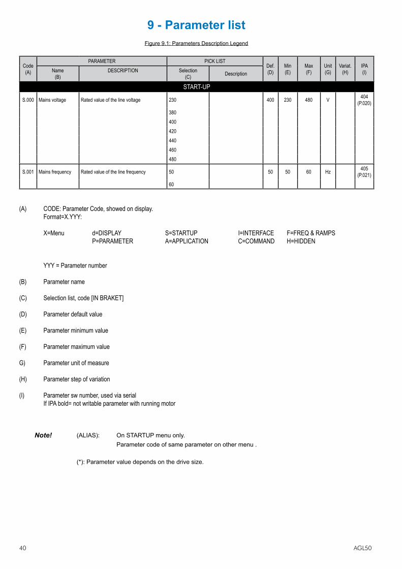
40 AGL50
9 - Parameter listFigure 9.1: Parameters Description Legend
Code(A)
PARAMETER PICK LISTDef.(D)
Min(E)
Max(F)
Unit(G)
Variat.(H)
IPA(I)Name
(B)DESCRIPTION Selection
(C) Description
START-UP
S.000 Mains voltage Rated value of the line voltage 230 400 230 480 V 404 (P.020)
380400420440460480
S.001 Mains frequency Rated value of the line frequency 50 50 50 60 Hz 405 (P.021)
60
(A) CODE: Parameter Code, showed on display. Format=X.YYY: X=Menu d=DISPLAY S=STARTUP I=INTERFACE F=FREQ & RAMPS P=PARAMETER A=APPLICATION C=COMMAND H=HIDDEN
YYY = Parameter number
(B) Parameter name
(C) Selection list, code [IN BRAKET]
(D) Parameter default value
(E) Parameter minimum value
(F) Parameter maximum value
G) Parameter unit of measure
(H) Parameter step of variation
(I) Parameter sw number, used via serial If IPA bold= not writable parameter with running motor
Note! (ALIAS): On STARTUP menu only. Parameter code of same parameter on other menu .
(*): Parameter value depends on the drive size.

AGL50 41
CodePARAMETER PICK LIST
Def. Min Max Unit Variat. IPAName DESCRIPTION Selection Description
DISPLAYd.000 Output frequency Drive output frequency Hz 0.01 001d.001 Frequency ref Drive frequency reference Hz 0.01 002d.002 Output current Drive output current (rms) A 0.1 003d.003 Output voltage Drive output voltage (rms) V 1 004d.004 DC link voltage DC Bus drive voltage (DC) V 1 005d.005 Power factor Power factor 0.01 006d.006 Power [kW] Inverter output power kW 0.01 007d.007 Output speed Drive output speed mm/s 1 008d.008 Speed ref Drive speed reference (d.001)*(P.600) mm/s 1 009
d.050 Heatsink temp Drive heatsink temperature (linear sensor measured) °C 1 010
d.051 Drive OL Drive overload (100% = alarm threshold) % 0.1 011d.052 Motor OL Motor overload (100% = alarm threshold) % 0.1 012
d.053 Brake res OL Braking resistor overload (100%=alarm thr) % 0.1 013
d.100 Dig inp status Digital inputs status acquired by the drive (terminal or virtual) 014
d.101 Term inp status Digital inputs terminal status of the drive regulat. Board 015
d.102 Vir dig inp stat Virtual digital inputs status from drive serial link 016
d.120 Exp dig inp stat Expansion digital inputs status (optional terminal or virtual) 017
d.121 Exp term inp Expansion digital inputs terminal status of the drive expansion board 018
d.122 Vir exp dig inp Expansion virtual digital inputs status from drive serial link 019
d.150 Dig out statusDigital outputs status on the terminals of the drive regulation board (commanded by DO functions or virtual DO)
020
d.151 Drv dig out sta Digital outputs status, commanded by DO functions 021
d.152 Vir dig out sta Virtual digital outputs status, commanded via serial link 022
d.170 Exp dig out sta
Expansion digital outputs status on the terminals of the drive regulation board (commanded by DO functions or virtual DO)
023
d.171 Exp DrvDigOutSta Expansion digital outputs status, com-manded by DO functions 024
d.172 Exp VirDigOutSta Expansion virtual digital outputs status, commanded via serial link 025
d.200 An in 1 cnf mon Analog input 1 destination; it shows the function associated to this analog input [0] Null funct 026
[1] Freq ref 1[2] Freq ref 2 [3] Bst lev fact[4] OT lev fact[5] Vred lev fac[6] DCB lev fact[7] RampExt fact[8] Freq Ref fact[9] SpdPI LimFac[10] MltFrq ch 1[11] MltFrq ch 2
d.201 An in 1 monitor Analog input 1 output block % value 027d.202 An in 1 term mon Analog input 1 input block % value 028
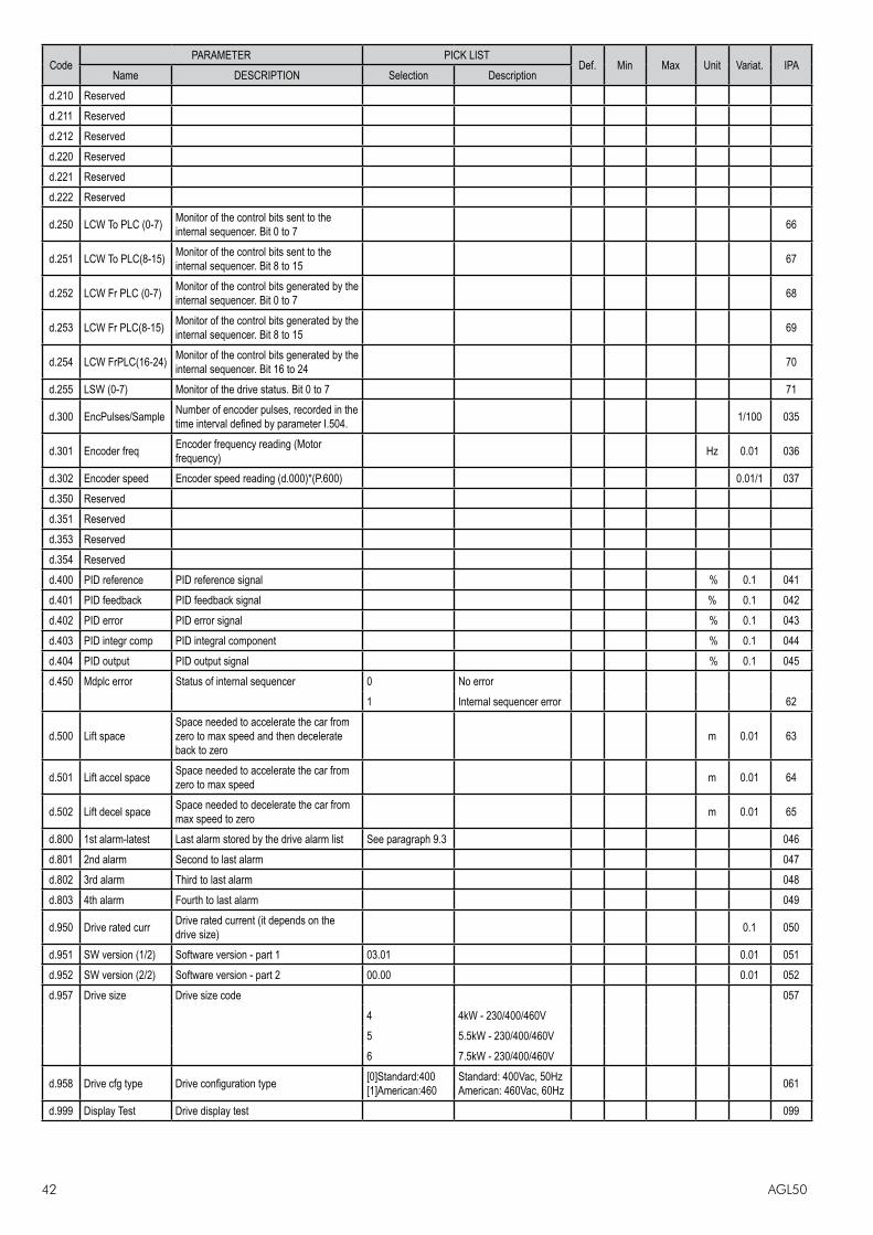
42 AGL50
CodePARAMETER PICK LIST
Def. Min Max Unit Variat. IPAName DESCRIPTION Selection Description
d.210 Reservedd.211 Reservedd.212 Reservedd.220 Reservedd.221 Reservedd.222 Reserved
d.250 LCW To PLC (0-7) Monitor of the control bits sent to the internal sequencer. Bit 0 to 7 66
d.251 LCW To PLC(8-15) Monitor of the control bits sent to the internal sequencer. Bit 8 to 15 67
d.252 LCW Fr PLC (0-7) Monitor of the control bits generated by the internal sequencer. Bit 0 to 7 68
d.253 LCW Fr PLC(8-15) Monitor of the control bits generated by the internal sequencer. Bit 8 to 15 69
d.254 LCW FrPLC(16-24) Monitor of the control bits generated by the internal sequencer. Bit 16 to 24 70
d.255 LSW (0-7) Monitor of the drive status. Bit 0 to 7 71
d.300 EncPulses/Sample Number of encoder pulses, recorded in the time interval defined by parameter I.504. 1/100 035
d.301 Encoder freq Encoder frequency reading (Motor frequency) Hz 0.01 036
d.302 Encoder speed Encoder speed reading (d.000)*(P.600) 0.01/1 037d.350 Reservedd.351 Reservedd.353 Reservedd.354 Reservedd.400 PID reference PID reference signal % 0.1 041d.401 PID feedback PID feedback signal % 0.1 042d.402 PID error PID error signal % 0.1 043d.403 PID integr comp PID integral component % 0.1 044d.404 PID output PID output signal % 0.1 045d.450 Mdplc error Status of internal sequencer 0 No error
1 Internal sequencer error 62
d.500 Lift spaceSpace needed to accelerate the car from zero to max speed and then decelerate back to zero
m 0.01 63
d.501 Lift accel space Space needed to accelerate the car from zero to max speed m 0.01 64
d.502 Lift decel space Space needed to decelerate the car from max speed to zero m 0.01 65
d.800 1st alarm-latest Last alarm stored by the drive alarm list See paragraph 9.3 046d.801 2nd alarm Second to last alarm 047d.802 3rd alarm Third to last alarm 048d.803 4th alarm Fourth to last alarm 049
d.950 Drive rated curr Drive rated current (it depends on the drive size) 0.1 050
d.951 SW version (1/2) Software version - part 1 03.01 0.01 051d.952 SW version (2/2) Software version - part 2 00.00 0.01 052d.957 Drive size Drive size code 057
4 4kW - 230/400/460V 5 5.5kW - 230/400/460V 6 7.5kW - 230/400/460V
d.958 Drive cfg type Drive configuration type [0]Standard:400 [1]American:460
Standard: 400Vac, 50Hz American: 460Vac, 60Hz 061
d.999 Display Test Drive display test 099

AGL50 43
CodePARAMETER PICK LIST
Def. Min Max Unit Variat. IPAName DESCRIPTION Selection Description
START-UP
S.000 Mains voltage Rated value of the line voltage 230 400 230 480 V 404 (P.020)
380400420440460480
S.001 Mains frequency Rated value of the line frequency 50 50 50 60 Hz 405 (P.021)
60
S.100 Base voltage Motor base (rated) voltage 380 50 528 V 1 413 (P.061)
S.101 Base frequency Rated frequency of the motor 50 25 250 Hz 0.1 414 (P.062)
S.150 Motor rated curr Rated current of the motor (*) (*) (*) A 0.1 406 (P.040)
S.151 Motor pole pairs Pole Pairs of the motor 2 1 60 0.01 407 (P.041)
S.152 Motor power fact Motor power factor (*) 0.01 1 0.01 408 (P.042)
S.153 Motor stator R Measurement of the stator resistance of the motor (*) 0 99.99 ohm 409
(P.043)
S.170 Measure stator R Motor Autotune command Off (1) (1) (2) 806 (C.100)
do
S.180 Car max speed Speed of the lift car when the inverter output frequency is equal to S.101 0.50 0.01 5.00 m/s 0.01 1323
(A.090)
S.200 Frequency ref 0 Digital reference frequency 0 10.0 -F.020 F.020 311 (F.100)
S.201 Frequency ref 1 Digital reference frequency 1 50.0 -F.020 F.020 312 (F.101)
S.202 Frequency ref 2 Digital reference frequency 2 0 -F.020 F.020 313 (F.102)
S.203 Frequency ref 3 Digital reference frequency 3 0 -F.020 F.020 314 (F.103)
S.204 Frequency ref 4 Digital reference frequency 4 0 -F.020 F.020 315 (F.104)
S.205 Frequency ref 5 Digital reference frequency 5 0 -F.020 F.020 316 (F.105)
S.206 Frequency ref 6 Digital reference frequency 6 0 -F.020 F.020 317 (F.106)
S.207 Frequency ref 7 Digital reference frequency 7 0 -F.020 F.020 318 (F.107)
S.220 Smooth start frq Frequency reference during smooth start 2.0 -F.020 F.020 327 (F.116)
S.225 Ramp factor 1 Multiplier for acc/dec and jerks of ramp sets 1 and 3 1.00 0.01 2.50 0.01 1324
(A.091)
S.226 Ramp factor 2 Multiplier for acc/dec and jerks of ramp sets 2 and 4 1.00 0.01 2.50 0.01 1327
(A.092)
S.230 Jerk acc ini 1 Jerk applied at the beginning of an accele-ration with ramp set 1 0.50 0.01 10.00 m/s3 0.01 343
(F.251)
S.231 Acceleration 1 Linear acceleration with ramp set 1 0.60 0.01 5.00 m/s2 0.01 329 (F.201)
S.232 Jerk acc end 1 Jerk applied at the end of an acceleration with ramp set 1 1.40 0.01 10.00 m/s3 0.01 344
(F.252)
S.233 Jerk dec ini 1 Jerk applied at the beginning of a decele-ration with ramp set 1 1.40 0.01 10.00 m/s3 0.01 345
(F.253)
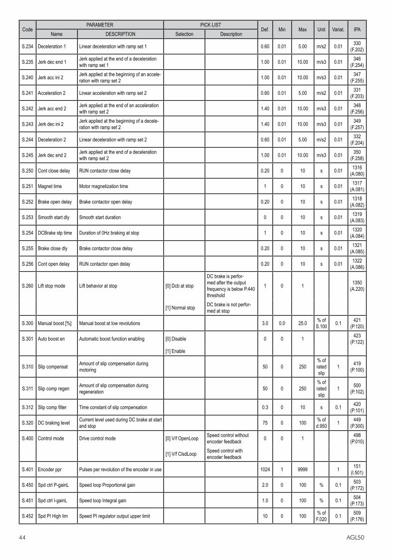
44 AGL50
CodePARAMETER PICK LIST
Def. Min Max Unit Variat. IPAName DESCRIPTION Selection Description
S.234 Deceleration 1 Linear deceleration with ramp set 1 0.60 0.01 5.00 m/s2 0.01 330 (F.202)
S.235 Jerk dec end 1 Jerk applied at the end of a deceleration with ramp set 1 1.00 0.01 10.00 m/s3 0.01 346
(F.254)
S.240 Jerk acc ini 2 Jerk applied at the beginning of an accele-ration with ramp set 2 1.00 0.01 10.00 m/s3 0.01 347
(F.255)
S.241 Acceleration 2 Linear acceleration with ramp set 2 0.60 0.01 5.00 m/s2 0.01 331 (F.203)
S.242 Jerk acc end 2 Jerk applied at the end of an acceleration with ramp set 2 1.40 0.01 10.00 m/s3 0.01 348
(F.256)
S.243 Jerk dec ini 2 Jerk applied at the beginning of a decele-ration with ramp set 2 1.40 0.01 10.00 m/s3 0.01 349
(F.257)
S.244 Deceleration 2 Linear deceleration with ramp set 2 0.60 0.01 5.00 m/s2 0.01 332 (F.204)
S.245 Jerk dec end 2 Jerk applied at the end of a deceleration with ramp set 2 1.00 0.01 10.00 m/s3 0.01 350
(F.258)
S.250 Cont close delay RUN contactor close delay 0.20 0 10 s 0.01 1316 (A.080)
S.251 Magnet time Motor magnetization time 1 0 10 s 0.01 1317 (A.081)
S.252 Brake open delay Brake contactor open delay 0.20 0 10 s 0.01 1318 (A.082)
S.253 Smooth start dly Smooth start duration 0 0 10 s 0.01 1319 (A.083)
S.254 DCBrake stp time Duration of 0Hz braking at stop 1 0 10 s 0.01 1320 (A.084)
S.255 Brake close dly Brake contactor close delay 0.20 0 10 s 0.01 1321 (A.085)
S.256 Cont open delay RUN contactor open delay 0.20 0 10 s 0.01 1322 (A.086)
S.260 Lift stop mode Lift behavior at stop [0] Dcb at stop
DC brake is perfor-med after the output frequency is below P.440 threshold
1 0 1 1350 (A.220)
[1] Normal stop DC brake is not perfor-med at stop
S.300 Manual boost [%] Manual boost at low revolutions 3.0 0.0 25.0 % of S.100 0.1 421
(P.120)
S.301 Auto boost en Automatic boost function enabling [0] Disable 0 0 1 423 (P.122)
[1] Enable
S.310 Slip compensat Amount of slip compensation during motoring 50 0 250
% of rated slip
1 419 (P.100)
S.311 Slip comp regen Amount of slip compensation during regeneration 50 0 250
% of rated slip
1 500 (P.102)
S.312 Slip comp filter Time constant of slip compensation 0.3 0 10 s 0.1 420 (P.101)
S.320 DC braking level Current level used during DC brake at start and stop 75 0 100 % of
d.950 1 449 (P.300)
S.400 Control mode Drive control mode [0] V/f OpenLoop Speed control without encoder feedback 0 0 1 498
(P.010)
[1] V/f ClsdLoop Speed control with encoder feedback
S.401 Encoder ppr Pulses per revolution of the encoder in use 1024 1 9999 1 151 (I.501)
S.450 Spd ctrl P-gainL Speed loop Proportional gain 2.0 0 100 % 0.1 503 (P.172)
S.451 Spd ctrl I-gainL Speed loop Integral gain 1.0 0 100 % 0.1 504 (P.173)
S.452 Spd PI High lim Speed PI regulator output upper limit 10 0 100 % of F.020 0.1 509
(P.176)
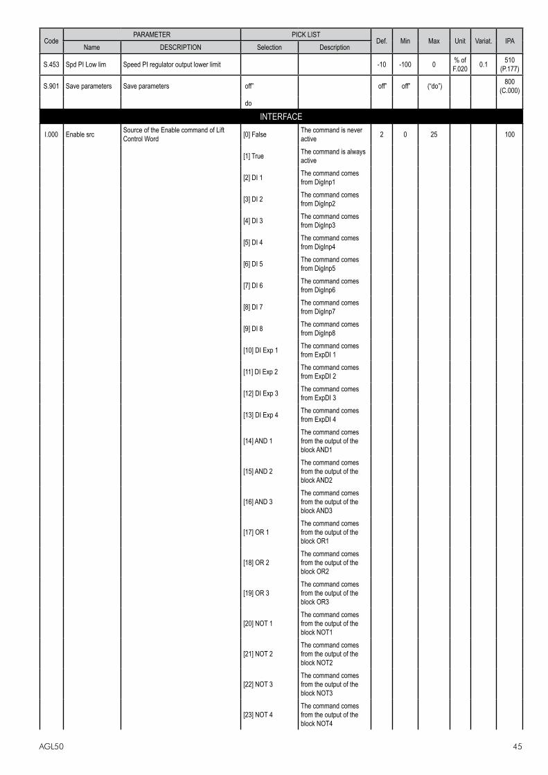
AGL50 45
CodePARAMETER PICK LIST
Def. Min Max Unit Variat. IPAName DESCRIPTION Selection Description
S.453 Spd PI Low lim Speed PI regulator output lower limit -10 -100 0 % of F.020 0.1 510
(P.177)
S.901 Save parameters Save parameters off” off” off” (“do”) 800 (C.000)
do
INTERFACE
I.000 Enable src Source of the Enable command of Lift Control Word [0] False The command is never
active 2 0 25 100
[1] True The command is always active
[2] DI 1 The command comes from DigInp1
[3] DI 2 The command comes from DigInp2
[4] DI 3 The command comes from DigInp3
[5] DI 4 The command comes from DigInp4
[6] DI 5 The command comes from DigInp5
[7] DI 6 The command comes from DigInp6
[8] DI 7 The command comes from DigInp7
[9] DI 8 The command comes from DigInp8
[10] DI Exp 1 The command comes from ExpDI 1
[11] DI Exp 2 The command comes from ExpDI 2
[12] DI Exp 3 The command comes from ExpDI 3
[13] DI Exp 4 The command comes from ExpDI 4
[14] AND 1The command comes from the output of the block AND1
[15] AND 2The command comes from the output of the block AND2
[16] AND 3The command comes from the output of the block AND3
[17] OR 1The command comes from the output of the block OR1
[18] OR 2The command comes from the output of the block OR2
[19] OR 3The command comes from the output of the block OR3
[20] NOT 1The command comes from the output of the block NOT1
[21] NOT 2The command comes from the output of the block NOT2
[22] NOT 3The command comes from the output of the block NOT3
[23] NOT 4The command comes from the output of the block NOT4

46 AGL50
CodePARAMETER PICK LIST
Def. Min Max Unit Variat. IPAName DESCRIPTION Selection Description
[24] FrqSel matchThe command is coming from the output of the block Freq Sel match
[25] ShortFloorFl The command is the short floor flag
I.001 Run Fwd src Source of the Run Forward command of LCW As for I.000 3 0 25 101
I.002 Run Rev src Source of the Run Reverse command of LCW As for I.000 4 0 25 102
I.003 Freq Sel 1 src Source of the Frequency Selector 1 of LCW As for I.000 5 0 25 103
I.004 Freq Sel 2 src Source of the Frequency Selector 2 of LCW As for I.000 6 0 25 104
I.005 Freq Sel 3 src Source of the Frequency Selector 3 of LCW As for I.000 7 0 25 105
I.006 Freq Sel 4 src Source of the Frequency Selector 4 of LCW As for I.000 0 0 25 106
I.007 Ramp Sel 1 src Source of the Ramp Selector 1 of LCW As for I.000 25 0 25 107I.008 Ramp Sel 2 src Source of the Ramp Selector 1 of LCW As for I.000 0 0 25 108
I.009 Ext fault src Source of the External Fault command of LCW As for I.000 8 0 25 109
I.010 Faul reset src Source of the Fault Reset command of LCW As for I.000 9 0 25 110
I.011 Bak pwr act src Source of the Backup Power Supply Active command of LCW As for I.000 0 0 25 111
I.012 Forced stop src Source of the Forced Stop command of LCW 0 0 25 185
I.100 Dig output 1 cfg Digital output 1 configuration [0] Drive Ready 51 0 55 112[1] Alarm state[2] Not in alarm[3] Motor run[4] Motor stop[5] REV rotation[6] Steady state[7] Ramping[8] UV running[9] Out trq>thr[10] Current lim[11] DC-link lim[12] Limit active[13] Autocapt run[14] BU overload[15] Neg pwrfact[16] PID err ><[17] PID err>thr[18] PID err<thr[19] PIDer><(inh)[20] PIDerr>(inh)[21] PIDerr<(inh)[22] FWD enc rot[23] REV enc rot[24] Encoder stop[25] Encoder run[26] Extern fault[27] No ext fault[28] Serial TO[29] freq=thr1
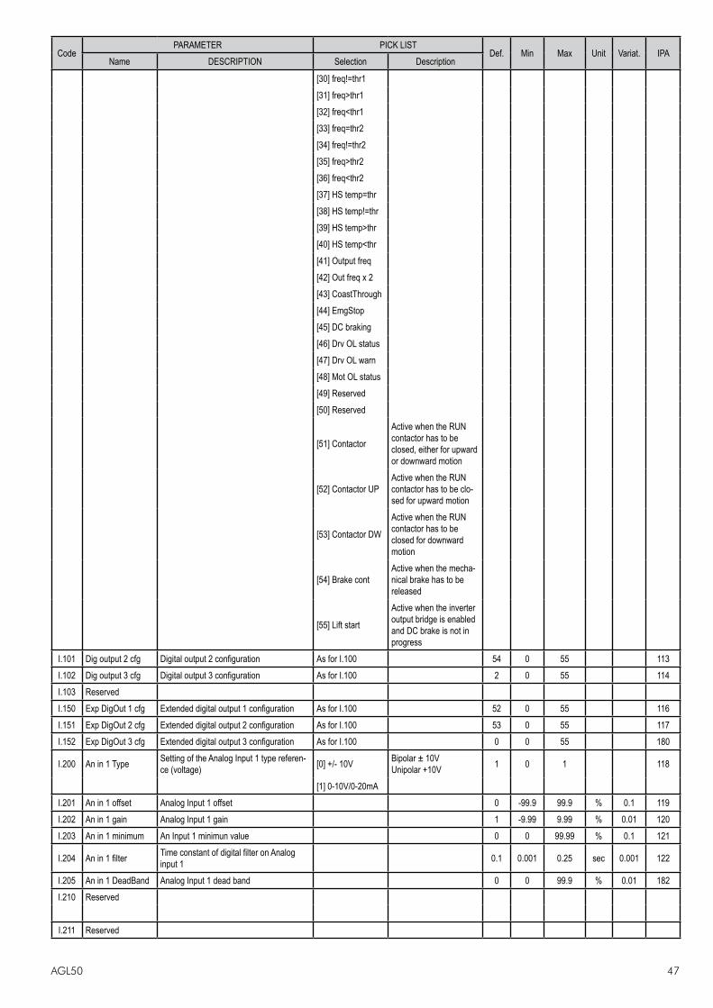
AGL50 47
CodePARAMETER PICK LIST
Def. Min Max Unit Variat. IPAName DESCRIPTION Selection Description
[30] freq!=thr1[31] freq>thr1[32] freq<thr1[33] freq=thr2[34] freq!=thr2[35] freq>thr2[36] freq<thr2[37] HS temp=thr[38] HS temp!=thr[39] HS temp>thr[40] HS temp<thr[41] Output freq[42] Out freq x 2[43] CoastThrough[44] EmgStop[45] DC braking[46] Drv OL status[47] Drv OL warn[48] Mot OL status[49] Reserved[50] Reserved
[51] Contactor
Active when the RUN contactor has to be closed, either for upward or downward motion
[52] Contactor UPActive when the RUN contactor has to be clo-sed for upward motion
[53] Contactor DW
Active when the RUN contactor has to be closed for downward motion
[54] Brake contActive when the mecha-nical brake has to be released
[55] Lift start
Active when the inverter output bridge is enabled and DC brake is not in progress
I.101 Dig output 2 cfg Digital output 2 configuration As for I.100 54 0 55 113I.102 Dig output 3 cfg Digital output 3 configuration As for I.100 2 0 55 114I.103 ReservedI.150 Exp DigOut 1 cfg Extended digital output 1 configuration As for I.100 52 0 55 116I.151 Exp DigOut 2 cfg Extended digital output 2 configuration As for I.100 53 0 55 117I.152 Exp DigOut 3 cfg Extended digital output 3 configuration As for I.100 0 0 55 180
I.200 An in 1 Type Setting of the Analog Input 1 type referen-ce (voltage) [0] +/- 10V Bipolar ± 10V
Unipolar +10V 1 0 1 118
[1] 0-10V/0-20mA I.201 An in 1 offset Analog Input 1 offset 0 -99.9 99.9 % 0.1 119I.202 An in 1 gain Analog Input 1 gain 1 -9.99 9.99 % 0.01 120I.203 An in 1 minimum An Input 1 minimun value 0 0 99.99 % 0.1 121
I.204 An in 1 filter Time constant of digital filter on Analog input 1 0.1 0.001 0.25 sec 0.001 122
I.205 An in 1 DeadBand Analog Input 1 dead band 0 0 99.9 % 0.01 182I.210 Reserved
I.211 Reserved
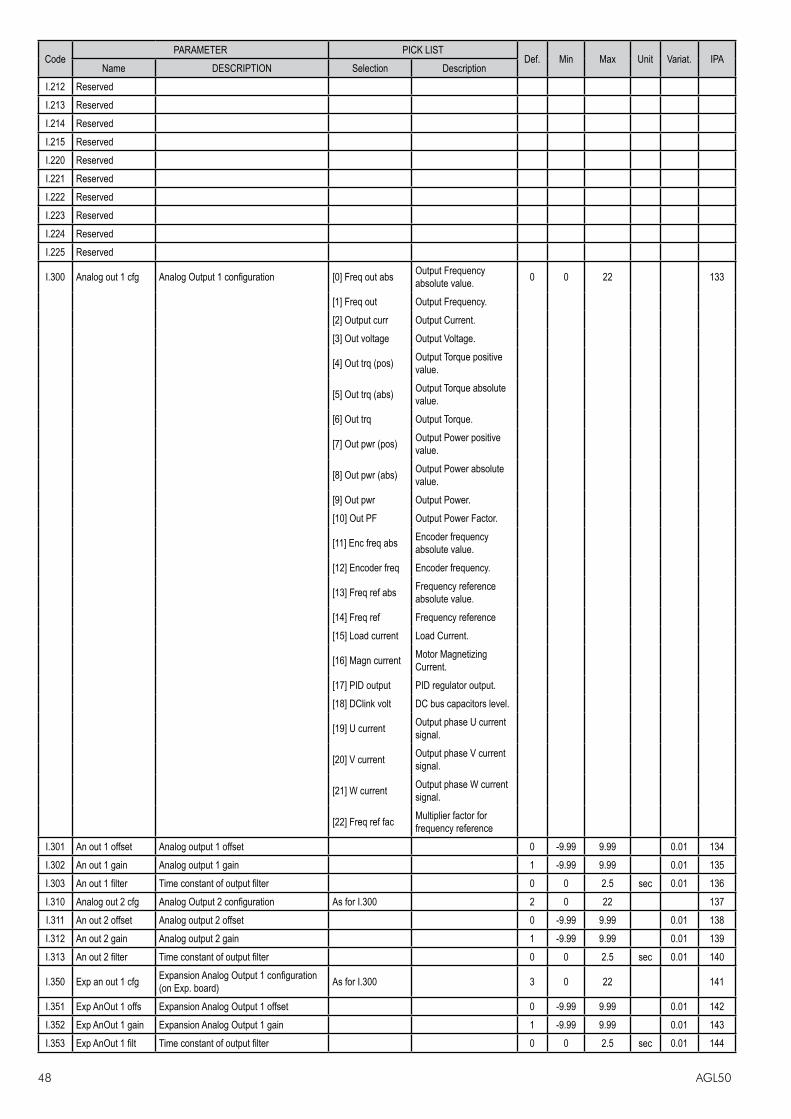
48 AGL50
CodePARAMETER PICK LIST
Def. Min Max Unit Variat. IPAName DESCRIPTION Selection Description
I.212 ReservedI.213 ReservedI.214 ReservedI.215 ReservedI.220 ReservedI.221 ReservedI.222 ReservedI.223 ReservedI.224 ReservedI.225 Reserved
I.300 Analog out 1 cfg Analog Output 1 configuration [0] Freq out abs Output Frequency absolute value. 0 0 22 133
[1] Freq out Output Frequency.[2] Output curr Output Current.[3] Out voltage Output Voltage.
[4] Out trq (pos) Output Torque positive value.
[5] Out trq (abs) Output Torque absolute value.
[6] Out trq Output Torque.
[7] Out pwr (pos) Output Power positive value.
[8] Out pwr (abs) Output Power absolute value.
[9] Out pwr Output Power. [10] Out PF Output Power Factor.
[11] Enc freq abs Encoder frequency absolute value.
[12] Encoder freq Encoder frequency.
[13] Freq ref abs Frequency reference absolute value.
[14] Freq ref Frequency reference [15] Load current Load Current.
[16] Magn current Motor Magnetizing Current.
[17] PID output PID regulator output.[18] DClink volt DC bus capacitors level.
[19] U current Output phase U current signal.
[20] V current Output phase V current signal.
[21] W current Output phase W current signal.
[22] Freq ref fac Multiplier factor for frequency reference
I.301 An out 1 offset Analog output 1 offset 0 -9.99 9.99 0.01 134I.302 An out 1 gain Analog output 1 gain 1 -9.99 9.99 0.01 135I.303 An out 1 filter Time constant of output filter 0 0 2.5 sec 0.01 136I.310 Analog out 2 cfg Analog Output 2 configuration As for I.300 2 0 22 137I.311 An out 2 offset Analog output 2 offset 0 -9.99 9.99 0.01 138I.312 An out 2 gain Analog output 2 gain 1 -9.99 9.99 0.01 139I.313 An out 2 filter Time constant of output filter 0 0 2.5 sec 0.01 140
I.350 Exp an out 1 cfg Expansion Analog Output 1 configuration (on Exp. board) As for I.300 3 0 22 141
I.351 Exp AnOut 1 offs Expansion Analog Output 1 offset 0 -9.99 9.99 0.01 142I.352 Exp AnOut 1 gain Expansion Analog Output 1 gain 1 -9.99 9.99 0.01 143I.353 Exp AnOut 1 filt Time constant of output filter 0 0 2.5 sec 0.01 144

AGL50 49
CodePARAMETER PICK LIST
Def. Min Max Unit Variat. IPAName DESCRIPTION Selection Description
I.400 Inp by serial en Virtual Digital enabling 0 0 255 145
I.410 Exp in by ser en Expansion Virtual Digital Inputs enabling 0 0 15 146
I.420 Out by serial en Virtual Digital Outputs setting enabling 0 0 15 147I.430 Exp OutBySer en Expansion Virtual Digital Outputs enabling 0 0 3 148I.450 An out by ser en Virtual Analog Outputs enabling 0 0 255 149
I.500 Encoder enable Enabling of the encoder measure [0] Disable Encoder measure disabled. 0 0 1 150
[1] Enable Encoder measure enabled.
I.501 Encoder ppr Encoder nameplate pulses per revolution 1024 1 9999 151I.502 Enc channels cfg Encoder channels configuration [0] One Channel A (K1) encoder channel 1 0 1 152
[1] Two Channels A and B (K1 and K2) encoder channels
I.503 Enc spd mul fact Multiplier factor of the encoder pulses, set in the I.501 1 0.01 99.99 153
I.504 Enc update time Encoder pulses sampling time [0] 1ms 0 0 5 154[1] 4ms[2] 16ms[3] 0.25s[4] 1s[5] 5s
I.505 Enc power supply Encoder power supply level [0] 5.2V 0 0 3 181[1] 5.6V[2] 8.3V[3] 8.7V
I.506 Enc fault enable Enable ENC alarm, Encoder cable break [0] Disable Encoder alarm disabled 0 0 1 197[1] Enable Encoder alarm enabled
I.600 Serial link cfg Serial line configuration protocol & mode Type(DataBit) Parity (StopBit) 4 0 5 0.1 155
[0] FoxLink 7E1 FoxLink 7E1 (7) Even (1 )
[1] FoxLink 701 FoxLink 7O1 (7) Odd (1)
[2] FoxLink 7N2 FoxLink 7N2 (7) None (2)
[3] FoxLink 8N1 FoxLink 7O1 (8) None (1)
[4] ModBus 8N1 Modbus 8N1 (8) None (1)
[5] JBus 8N1 Jbus 8N1 (8) None (1) I.601 Serial link bps Serial line baudrate [0] 600 baud 600 baud rate 4 0 6 156
[1] 1200 baud 1200 baud rate [2] 2400 baud 2400 baud rate [3] 4800 baud 4800 baud rate [4] 9600 baud 9600 baud rate [5] 19200 baud 19200 baud rate [6] 38400 baud 38400 baud rate
I.602 Device address Serial line address of the drive 1 0 99 1 157I.603 Ser answer delay Serial line answer delay time 1 0 250 msec 1 158I.604 Serial timeout Serial line transmission timeout 0 0 25 sec 0.1 159
I.605 En timeout alm Setting time out alarm [0] Disable Drive NOT in alarm and signal on a digital output 0 0 1 160
[1] Enable Drive IN alarm and signal on a digital output
I.700 Reserved Expansion optional 1 card typeI.701 Reserved

50 AGL50
CodePARAMETER PICK LIST
Def. Min Max Unit Variat. IPAName DESCRIPTION Selection Description
I.750 ReservedI.751 ReservedI.752 ReservedI.753 ReservedI.754 ReservedI.760 ReservedI.761 ReservedI.762 ReservedI.763 ReservedI.764 ReservedI.765 ReservedI.770 ReservedI.771 ReservedI.772 ReservedI.773 ReservedI.774 ReservedI.775 Reserved
FREQ & RAMP
F.000 Motorpot ref Motopot reference (it can be set using up and down commands) 0 0 F.020 Hz 0.01 300
F.010 Mp Acc/Dec time Motorpot Accel. and Decel. ramp time 10 0.1 999.9 sec 0.1 301F.011 Motorpot offset Motopotentiometer minimum reference 0 0 F.020 Hz 0.1 302F.012 Mp output mode Unipolar / bipolar Motorpotentiometer [0] Unipolar 0 0 1 303
[1] BipolarF.013 Mp auto save Motopotenziometer auto save function [0] Disable 1 0 1 304
[1] Enable
F.014 MpRef at stopBehavior of the frequency reference from Motorpotentiometer during a Stop sequence
[0] Last value Mot. reference will retain its current value 0 0 1 351
[1] Follow ramp
Mot. reference will ramp down to zero, following the deceleration ramp in use
F.020 Max ref freq Motor maximum frequency value (for both directions) 50 25 250 Hz 0.1 305
F.021 Min ref freq Minimum frequency value 0 0 F.020 Hz 0.1 306F.050 Ref 1 channel Source of the Reference 1 [0] Null Null 4 4 4 307
[1] Analog inp 1 Analog input 1[2] Analog inp 2 Analog input 2
[3] Freq ref x Frequency reference F.100 (S.203)
[4] Multispeed Multi frequncies
[5] Motorpotent Motorpotientometer reference
[6] Analog inp 3 Analog input 3[7] Encoder Encoder signal[8] Reserved
F.051 Ref 2 channel Source of the Reference 2 [0] Null Null 0 0 8 308[1] Analog inp 1 Analog input 1[2] Analog inp 2 Analog input 2
[3] Freq ref x Frequency reference F.101
[4] Multispeed Multispeed
[5] Motorpotent Motorpotientometer reference
[6] Analog inp 3 Analog input 3
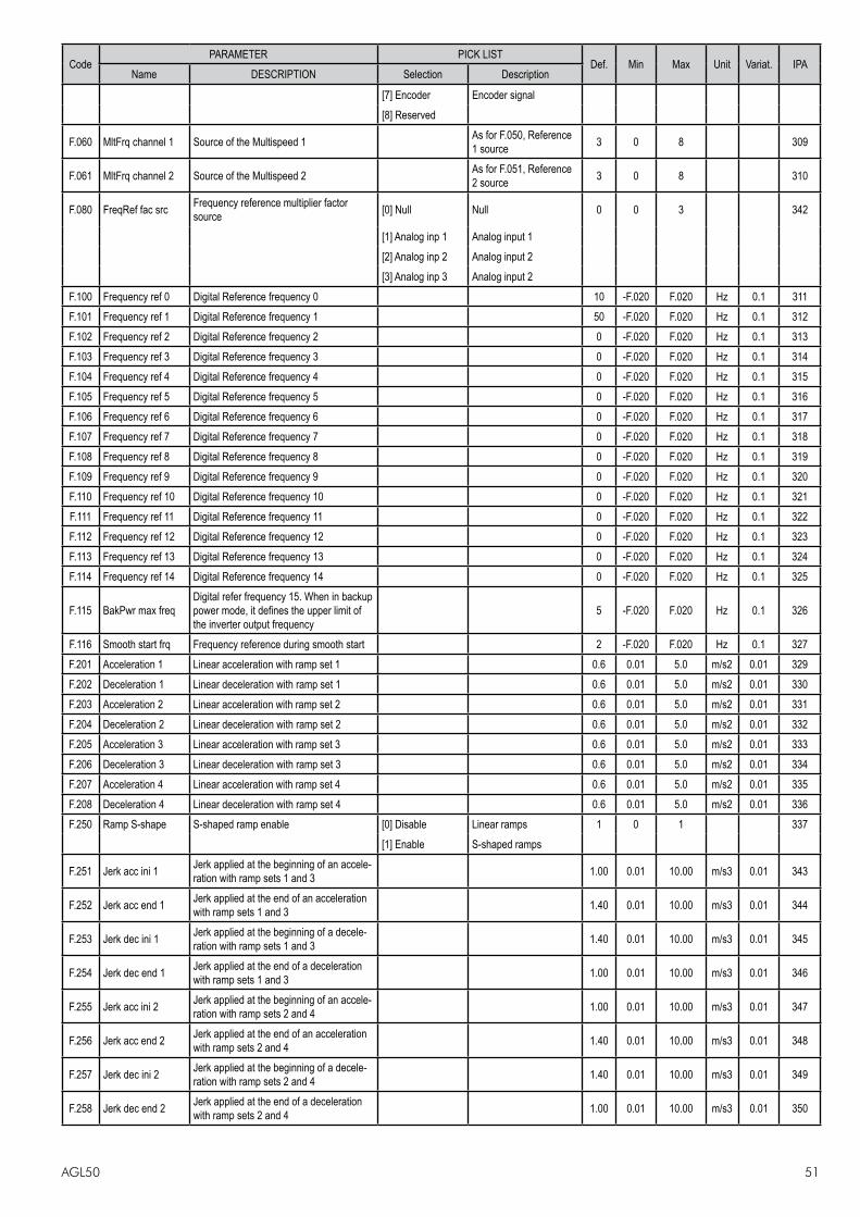
AGL50 51
CodePARAMETER PICK LIST
Def. Min Max Unit Variat. IPAName DESCRIPTION Selection Description
[7] Encoder Encoder signal[8] Reserved
F.060 MltFrq channel 1 Source of the Multispeed 1 As for F.050, Reference 1 source 3 0 8 309
F.061 MltFrq channel 2 Source of the Multispeed 2 As for F.051, Reference 2 source 3 0 8 310
F.080 FreqRef fac src Frequency reference multiplier factor source [0] Null Null 0 0 3 342
[1] Analog inp 1 Analog input 1[2] Analog inp 2 Analog input 2[3] Analog inp 3 Analog input 2
F.100 Frequency ref 0 Digital Reference frequency 0 10 -F.020 F.020 Hz 0.1 311F.101 Frequency ref 1 Digital Reference frequency 1 50 -F.020 F.020 Hz 0.1 312F.102 Frequency ref 2 Digital Reference frequency 2 0 -F.020 F.020 Hz 0.1 313F.103 Frequency ref 3 Digital Reference frequency 3 0 -F.020 F.020 Hz 0.1 314F.104 Frequency ref 4 Digital Reference frequency 4 0 -F.020 F.020 Hz 0.1 315F.105 Frequency ref 5 Digital Reference frequency 5 0 -F.020 F.020 Hz 0.1 316F.106 Frequency ref 6 Digital Reference frequency 6 0 -F.020 F.020 Hz 0.1 317F.107 Frequency ref 7 Digital Reference frequency 7 0 -F.020 F.020 Hz 0.1 318F.108 Frequency ref 8 Digital Reference frequency 8 0 -F.020 F.020 Hz 0.1 319F.109 Frequency ref 9 Digital Reference frequency 9 0 -F.020 F.020 Hz 0.1 320F.110 Frequency ref 10 Digital Reference frequency 10 0 -F.020 F.020 Hz 0.1 321F.111 Frequency ref 11 Digital Reference frequency 11 0 -F.020 F.020 Hz 0.1 322F.112 Frequency ref 12 Digital Reference frequency 12 0 -F.020 F.020 Hz 0.1 323F.113 Frequency ref 13 Digital Reference frequency 13 0 -F.020 F.020 Hz 0.1 324F.114 Frequency ref 14 Digital Reference frequency 14 0 -F.020 F.020 Hz 0.1 325
F.115 BakPwr max freqDigital refer frequency 15. When in backup power mode, it defines the upper limit of the inverter output frequency
5 -F.020 F.020 Hz 0.1 326
F.116 Smooth start frq Frequency reference during smooth start 2 -F.020 F.020 Hz 0.1 327F.201 Acceleration 1 Linear acceleration with ramp set 1 0.6 0.01 5.0 m/s2 0.01 329F.202 Deceleration 1 Linear deceleration with ramp set 1 0.6 0.01 5.0 m/s2 0.01 330F.203 Acceleration 2 Linear acceleration with ramp set 2 0.6 0.01 5.0 m/s2 0.01 331F.204 Deceleration 2 Linear deceleration with ramp set 2 0.6 0.01 5.0 m/s2 0.01 332F.205 Acceleration 3 Linear acceleration with ramp set 3 0.6 0.01 5.0 m/s2 0.01 333F.206 Deceleration 3 Linear deceleration with ramp set 3 0.6 0.01 5.0 m/s2 0.01 334F.207 Acceleration 4 Linear acceleration with ramp set 4 0.6 0.01 5.0 m/s2 0.01 335F.208 Deceleration 4 Linear deceleration with ramp set 4 0.6 0.01 5.0 m/s2 0.01 336F.250 Ramp S-shape S-shaped ramp enable [0] Disable Linear ramps 1 0 1 337
[1] Enable S-shaped ramps
F.251 Jerk acc ini 1 Jerk applied at the beginning of an accele-ration with ramp sets 1 and 3 1.00 0.01 10.00 m/s3 0.01 343
F.252 Jerk acc end 1 Jerk applied at the end of an acceleration with ramp sets 1 and 3 1.40 0.01 10.00 m/s3 0.01 344
F.253 Jerk dec ini 1 Jerk applied at the beginning of a decele-ration with ramp sets 1 and 3 1.40 0.01 10.00 m/s3 0.01 345
F.254 Jerk dec end 1 Jerk applied at the end of a deceleration with ramp sets 1 and 3 1.00 0.01 10.00 m/s3 0.01 346
F.255 Jerk acc ini 2 Jerk applied at the beginning of an accele-ration with ramp sets 2 and 4 1.00 0.01 10.00 m/s3 0.01 347
F.256 Jerk acc end 2 Jerk applied at the end of an acceleration with ramp sets 2 and 4 1.40 0.01 10.00 m/s3 0.01 348
F.257 Jerk dec ini 2 Jerk applied at the beginning of a decele-ration with ramp sets 2 and 4 1.40 0.01 10.00 m/s3 0.01 349
F.258 Jerk dec end 2 Jerk applied at the end of a deceleration with ramp sets 2 and 4 1.00 0.01 10.00 m/s3 0.01 350

52 AGL50
CodePARAMETER PICK LIST
Def. Min Max Unit Variat. IPAName DESCRIPTION Selection Description
F.260 Ramp extens src Source for the Ramp time extension function [0] Null Null 0 0 3 338
[1] Analog inp 1 Analog input 1[2] Analog inp 2 Analog input 2 [3] Analog inp 3 Analog input 3
F.270 Jump amplitude Jump frequencies hysteresis 0 0 100 Hz 0.1 339F.271 Jump frequency 1 Jump frequency 1 0 0 250 Hz 0.1 340F.272 Jump frequency 2 Jump frequency 2 0 0 250 Hz 0.1 341
PARAMETER
P.000 Cmd source sel It defines the use of START and STOP commands [0] CtrlWordOnly 0 0 1 400
[1] CtlWrd & kpd
P.002 Reversal enable Reversal enabling [0] Disable Disabling reverse rotation 1 0 1 402
[1] Enable Enabling reverse rotation
P.003 Safety Safe start definition [0] OFFSTART allowed with RUN temirnal connected at the power on
1 0 1 403
[1] ONSTART not allowed with RUN temirnal connected at the power on
P.010 Control mode Drive control mode [0] V/f open loop V/f control w/o encoder feedback 0 0 1 498
[1] V/f clsd loop V/f control with encoder feedback
P.020 Mains voltage Rated value of the line voltage 230 400 230 480 V 404380400420440460480
P.021 Mains frequency Rated value of the line voltage frequency 50 50 50 60 Hz 40560
P.040 Motor rated curr Rated current of the motor (*) (*) (*) A 0.1 406P.041 Motor pole pairs Pole Pairs of the motor 2 1 60 407P.042 Motor power fact Motor power factor (*) 0.01 1 0.01 408
P.043 Motor stator R Measurement of the stator resistance of the motor (*) 0 99.99 ohm 0.01 409
P.044 Motor cooling Motor type cooling [0] Natural Self ventilated 0 0 1 410[1] Forced Assisted ventilation
P.045 Motor thermal K Motor thermal constant 30 1 120 min 411
P.060 V/f shape V/F Curve Type [0] Custom V/F curve defined by the user 1 0 2 412
[1] Linear Linear characteristic[2] Quadratic Quadratic characteristic
P.061 Base voltage Motor base (rated) voltage 380 50 528 V 1 413P.062 Base frequency Base frequency 50 25 500 Hz 0.1 414P.063 V/f interm volt V/F intermediate voltage 190 0 P.061 V 1 415P.064 V/f interm freq V/F intermediate frequency 25 1.0 P.062 Hz 0.1 416
P.080 Max output freq Maximum output frequency 110 0 110 % of F.020 1 417
P.081 Min output freq Minimum output frequency 0.0 0.0 25.0 % of F.020 0.1 418
P.100 Slip compensat Amount of slip compensation during motoring 50 0 250 % 1 419
P.101 Slip comp filter Time constant of slip compensation 0.3 0 10 sec 0.1 420

AGL50 53
CodePARAMETER PICK LIST
Def. Min Max Unit Variat. IPAName DESCRIPTION Selection Description
P.102 Slip comp regen Amount of slip compensation during regeneration 50 0 250 % 1 500
P.120 Manual boost [%] Torque boost level 3 0 25 % of P.061 1 421
P.121 Boost factor src Boost level source [0] Null Null 0 0 3 422[1] Analog inp 1 Analog input 1[2] Analog inp 2 Analog input 2 [3] Analog inp 3 Analog input 3
P.122 Auto boost en Automatic boost function enabling [0] Disable Automatic boost function disabled 0 0 1 423
[1] Enable Automatic boost function enabled
P.140 Magn curr gain Magnetizing current regulator gain 0 0 100 % 0.1 424P.160 Osc damping gain Damping gain 10 0 100 1 425P.170 Spd ctrl P-gainL Speed loop proportional gain (low speed) 2.0 0.0 100.0 % 0.1 501P.171 Spd ctrl I-gainL Speed loop integral gain (low speed) 1.0 0.0 100.0 % 0.1 502P.172 Spd ctrl P-gainH Speed loop proportional gain (high speed) 2.0 0.0 100.0 % 0.1 503P.173 Spd ctrl I-gainH Speed loop integral gain (high speed) 1.0 0.0 100.0 % 0.1 504P.174 Spd gain thr L Speed loop gain scheduling low threshold 0.0 0.0 F.020 Hz 0.1 507P.175 Spd gain thr H Speed loop gain scheduling high threshold 0.0 0.0 F.020 Hz 0.1 508
P.176 Spd PI High lim Speed regulator High limit 10.0 0.0 100.0 % of F.020 0.1 509
P.177 Spd PI Low lim Speed regulator Low limit -10.0 -100.0 0.0 % of F.020 0.1 510
P.178 SpdPI lim FacSrc Speed regulator limits factor source [0] Null Null 0 0 3 511[1] Analog inp 1 Analog input 1[2] Analog inp 2 Analog input 2 [3] Analog inp 3 Analog input 3
P.180 SW clamp enable Current clamp enable [0] Disable 1 0 1 426[1] Enable
P.181 Clamp alm HldOff Holf off time for current clamp alarm. Set to maximum (25.5s) to disable the alarm 5.0 0 25.5 s 0.1 512
P.200 Ramp CurLim mode Enable current limitation during ramp [0] None 0 0 2 427
[1] PI Limitator[2] Ramp freeze
P.201 Accel curr limit Current limit in acceleration phase (*) 20 (*) % of I nom 428
P.202 En lim in steady Enable current limitation in steady state [0] Disable 0 0 1 429[1] Enable
P.203 Curr lim steady Current limit at constant speed (*) 20 (*) % of I nom 1 430
P.204 Curr ctrl P-gain Current limiter proportional gain 10.0 0.1 100.0 % 431P.205 Curr ctrl I-gain Current limiter integral gain 30.0 0.0 100.0 % 0.1 432P.206 Curr ctr feedfwd Current limiter feed-forward 0 0 250 % 1 433
P.207 Decel curr limit Current limit in deceleration phase (*) 20 (*) % of I nom 1 494
P.220 En DC link ctrl Stall prevention during dec. for overvoltage [0] None None 0 0 2 434
[1] PI Limitator PI Limit regulator[2] Ramp freeze On/Off Ramp
P.221 DC-lnk ctr Pgain DC link voltage limiter proportional gain 3.0 0.1 100.0 % 0.1 435P.222 DC-lnk ctr Igain DC link voltage limiter integral gain 10.0 0.0 100.0 % 0.1 436P.223 DC-link ctr FF DC link voltage limiter feed-forward 0 0 250 % 1 437
P.240 OverTorque mode Overtorque mode [0] No Alm,Chk on0: Overtorque detection always active and Over-torque alarm disabled.
0 0 3 438
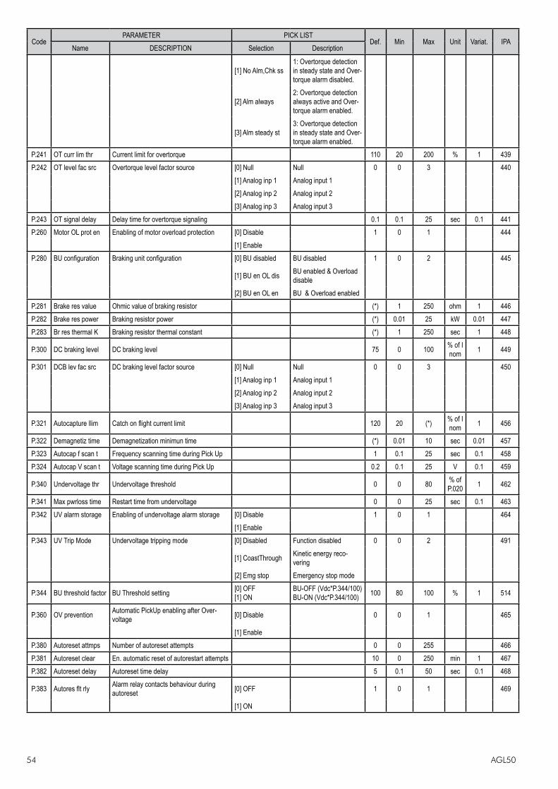
54 AGL50
CodePARAMETER PICK LIST
Def. Min Max Unit Variat. IPAName DESCRIPTION Selection Description
[1] No Alm,Chk ss1: Overtorque detection in steady state and Over-torque alarm disabled.
[2] Alm always2: Overtorque detection always active and Over-torque alarm enabled.
[3] Alm steady st3: Overtorque detection in steady state and Over-torque alarm enabled.
P.241 OT curr lim thr Current limit for overtorque 110 20 200 % 1 439P.242 OT level fac src Overtorque level factor source [0] Null Null 0 0 3 440
[1] Analog inp 1 Analog input 1[2] Analog inp 2 Analog input 2 [3] Analog inp 3 Analog input 3
P.243 OT signal delay Delay time for overtorque signaling 0.1 0.1 25 sec 0.1 441P.260 Motor OL prot en Enabling of motor overload protection [0] Disable 1 0 1 444
[1] EnableP.280 BU configuration Braking unit configuration [0] BU disabled BU disabled 1 0 2 445
[1] BU en OL dis BU enabled & Overload disable
[2] BU en OL en BU & Overload enabledP.281 Brake res value Ohmic value of braking resistor (*) 1 250 ohm 1 446P.282 Brake res power Braking resistor power (*) 0.01 25 kW 0.01 447P.283 Br res thermal K Braking resistor thermal constant (*) 1 250 sec 1 448
P.300 DC braking level DC braking level 75 0 100 % of I nom 1 449
P.301 DCB lev fac src DC braking level factor source [0] Null Null 0 0 3 450[1] Analog inp 1 Analog input 1[2] Analog inp 2 Analog input 2 [3] Analog inp 3 Analog input 3
P.321 Autocapture Ilim Catch on flight current limit 120 20 (*) % of I nom 1 456
P.322 Demagnetiz time Demagnetization minimun time (*) 0.01 10 sec 0.01 457P.323 Autocap f scan t Frequency scanning time during Pick Up 1 0.1 25 sec 0.1 458P.324 Autocap V scan t Voltage scanning time during Pick Up 0.2 0.1 25 V 0.1 459
P.340 Undervoltage thr Undervoltage threshold 0 0 80 % of P.020 1 462
P.341 Max pwrloss time Restart time from undervoltage 0 0 25 sec 0.1 463P.342 UV alarm storage Enabling of undervoltage alarm storage [0] Disable 1 0 1 464
[1] EnableP.343 UV Trip Mode Undervoltage tripping mode [0] Disabled Function disabled 0 0 2 491
[1] CoastThrough Kinetic energy reco-vering
[2] Emg stop Emergency stop mode
P.344 BU threshold factor BU Threshold setting [0] OFF[1] ON
BU-OFF (Vdc*P.344/100)BU-ON (Vdc*P.344/100) 100 80 100 % 1 514
P.360 OV prevention Automatic PickUp enabling after Over-voltage [0] Disable 0 0 1 465
[1] EnableP.380 Autoreset attmps Number of autoreset attempts 0 0 255 466P.381 Autoreset clear En. automatic reset of autorestart attempts 10 0 250 min 1 467P.382 Autoreset delay Autoreset time delay 5 0.1 50 sec 0.1 468
P.383 Autores flt rly Alarm relay contacts behaviour during autoreset [0] OFF 1 0 1 469
[1] ON
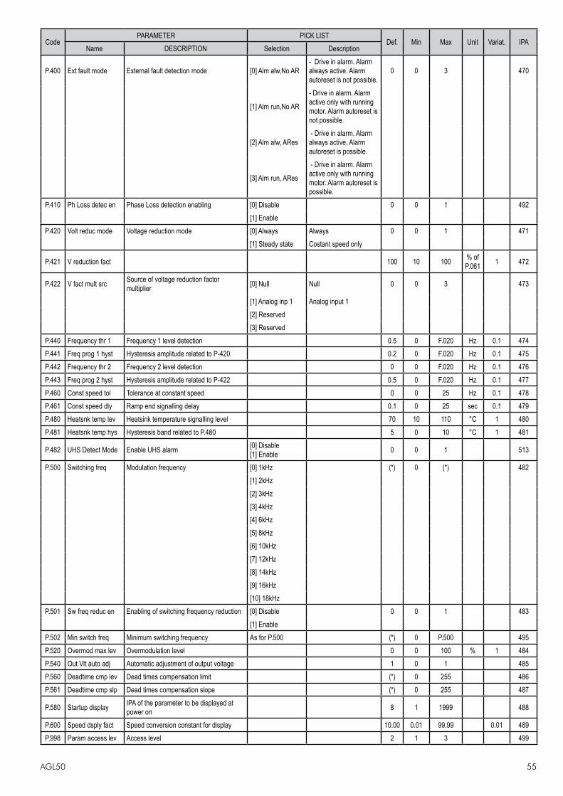
AGL50 55
CodePARAMETER PICK LIST
Def. Min Max Unit Variat. IPAName DESCRIPTION Selection Description
P.400 Ext fault mode External fault detection mode [0] Alm alw,No AR- Drive in alarm. Alarm always active. Alarm autoreset is not possible.
0 0 3 470
[1] Alm run,No AR
- Drive in alarm. Alarm active only with running motor. Alarm autoreset is not possible.
[2] Alm alw, ARes - Drive in alarm. Alarm always active. Alarm autoreset is possible.
[3] Alm run, ARes
- Drive in alarm. Alarm active only with running motor. Alarm autoreset is possible.
P.410 Ph Loss detec en Phase Loss detection enabling [0] Disable 0 0 1 492[1] Enable
P.420 Volt reduc mode Voltage reduction mode [0] Always Always 0 0 1 471[1] Steady state Costant speed only
P.421 V reduction fact 100 10 100 % of P.061 1 472
P.422 V fact mult src Source of voltage reduction factor multiplier [0] Null Null 0 0 3 473
[1] Analog inp 1 Analog input 1[2] Reserved[3] Reserved
P.440 Frequency thr 1 Frequency 1 level detection 0.5 0 F.020 Hz 0.1 474P.441 Freq prog 1 hyst Hysteresis amplitude related to P-420 0.2 0 F.020 Hz 0.1 475P.442 Frequency thr 2 Frequency 2 level detection 0 0 F.020 Hz 0.1 476P.443 Freq prog 2 hyst Hysteresis amplitude related to P-422 0.5 0 F.020 Hz 0.1 477P.460 Const speed tol Tolerance at constant speed 0 0 25 Hz 0.1 478P.461 Const speed dly Ramp end signalling delay 0.1 0 25 sec 0.1 479P.480 Heatsnk temp lev Heatsink temperature signalling level 70 10 110 °C 1 480P.481 Heatsnk temp hys Hysteresis band related to P.480 5 0 10 °C 1 481
P.482 UHS Detect Mode Enable UHS alarm [0] Disable[1] Enable 0 0 1 513
P.500 Switching freq Modulation frequency [0] 1kHz (*) 0 (*) 482[1] 2kHz[2] 3kHz[3] 4kHz[4] 6kHz[5] 8kHz[6] 10kHz[7] 12kHz[8] 14kHz[9] 16kHz[10] 18kHz
P.501 Sw freq reduc en Enabling of switching frequency reduction [0] Disable 0 0 1 483[1] Enable
P.502 Min switch freq Minimum switching frequency As for P.500 (*) 0 P.500 495P.520 Overmod max lev Overmodulation level 0 0 100 % 1 484P.540 Out Vlt auto adj Automatic adjustment of output voltage 1 0 1 485P.560 Deadtime cmp lev Dead times compensation limit (*) 0 255 486P.561 Deadtime cmp slp Dead times compensation slope (*) 0 255 487
P.580 Startup display IPA of the parameter to be displayed at power on 8 1 1999 488
P.600 Speed dsply fact Speed conversion constant for display 10.00 0.01 99.99 0.01 489P.998 Param access lev Access level 2 1 3 499

56 AGL50
CodePARAMETER PICK LIST
Def. Min Max Unit Variat. IPAName DESCRIPTION Selection Description
P.999 Param prot code Parameters protection code 0 Protection disabled
Stopped motor: possibili-ty to write all parameters. Running motor: some parameters are writing protected (IPA in bold)
0 0 3 490
1 Protection enabled (*) = only with motor stopped
All parameters are wri-ting protected excepted: - F000, F100..F116, multispeed function parameters - P999 Param prot code - C000 Save parameter (*) - C020 Alarm clear - H500..H511, serial line commands.
2 Protection enabled (*) = only with motor stopped
All parameters are wri-ting protected excepted: - P999 Param prot code - C000 Save parameter (*) - C020 Alarm clear - H500..H511, serial line commands.
3 Protection disabled
Stopped motor: possibili-ty to write all parameters. Running motor: some parameters are writing protected (IPA in bold) Possibility to execute Save parameter also with running motor.
APPLICATIONA.000 PID mode PID mode [0] Disable Null 0 0 6 1200
[1] Freq sum PID out in sum with ramp out ref (Feed forward)
[2] Freq directPID out not in sum with ramp out ref (no Feed forward)
[3] Volt sumPID out in sum with voltage ref from V/f curve (Feed forward)
[4] Volt directPID out not in sum with voltage ref from V/f curve (no Feed forward)
[5] Stand alonePID function as generic control (only with drive in RUN)
[6] St-Al always PID function as generic control (any drive status)
A.001 PID ref sel PID reference selector [0] Null Null 0 0 7 1201[1] Analog inp 1 Analog input 1[2] Analog inp 2 Analog input 2 [3] Analog inp 3 Analog input 3[4] Frequency ref Frequency reference[5] Ramp output Ramp output[6] Digital ref Internal reference[7] Encoder freq Encoder frequency
A.002 PID fbk sel PID feedback selector [0] Null Null 0 0 7 1202[1] Analog inp 1 Analog input 1[2] Analog inp 2 Analog input 2 [3] Analog inp 3 Analog input 3[4] Encoder freq Encoder frequency[5] Output curr Output peak current

AGL50 57
CodePARAMETER PICK LIST
Def. Min Max Unit Variat. IPAName DESCRIPTION Selection Description
[6] Output torque Output torque[7] Output power Output power
A.003 PID digital ref PID digital reference 0 -100 100 % 0.1 1203A.004 PID activat mode PID active in steady state only [0] Always 0 0 1 1204
[1] Steady stateA.005 PID-Encoder sync Enabling of encoder / PID synchronism [0] Disable 0 0 1 1205
[1] EnableA.006 PID err sign rev Error sign reversal [0] Disable 0 0 1 1206
[1] EnableA.007 PIDInteg init en Integral term initialization at start [0] Disable 0 0 1 1207
[1] EnableA.008 PID update time PID updating time 0 0 2.5 sec 0.01 1208A.050 PID Prop gain 1 Proportional term gain 1 0 0 99.99 0.01 1209A.051 PID Int tconst 1 Integral action time 1 99.99 0 99.99 0.01 1210A.052 PID Deriv gain 1 Derivative action time 1 0 0 99.99 0.01 1211A.053 PID Prop gain 2 Proportional term gain 2 0 0 99.99 0.01 1212A.054 PID Int tconst 2 Integral action time 2 99.99 0 99.99 0.01 1213A.055 PID Deriv gain 2 Derivative action time 2 0 0 99.99 0.01 1214A.056 PID high limit PID output upper limit 100 -100 100 % 0.1 1215A.057 PID low limit PID output lower limit -100 -100 100 % 0.1 1216A.058 PID max pos err PID max. positive error 5 0.1 100 % 0.1 1217A.059 PID min neg err PID max. negative error 5 0.1 100 % 0.1 1218A.080 Cont close delay RUN contactor close delay 0.20 0 10 s 0.01 1316A.081 Magnet time Motor magnetization time 1 0 10 s 0.01 1317A.082 Brake open delay Brake contactor open delay 0.20 0 10 s 0.01 1318A.083 Smooth start dly Smooth start duration 0 0 10 s 0.01 1319A.084 DCBrake stp time Duration of 0Hz braking at stop 1 0 10 s 0.01 1320A.085 Brake close dly Brake contactor close delay 0.20 0 10 s 0.01 1321A.086 Cont open delay RUN contactor open delay 0.20 0 10 s 0.01 1322
A.087 Current pres thr Current threshold for inverter output phases check 10 0 100 % 1 1325
A.088 Sel match code Code to be compared to the status of Freq selectors 0 0 15 1326
A.090 Car max speed Speed of the lift car when the inverter output frequency is equal to P.062 0.50 0.01 5.00 m/s 0.01 1323
A.091 Ramp factor 1 multiplier for acc/dec and jerks of ramp sets 1 and 3 1.00 0.01 2.50 0.01 1324
A.092 Ramp factor 2 multiplier for acc/dec and jerks of ramp sets 2 and 4 1.00 0.01 2.50 0.01 1327
A.220 Lift stop mode Lift behavior at stop [0] Dcb at stop
DC brake is perfor-med after the output frequency is below P.440 threshold
1 0 1 1350
[1] Normal stop DC brake is not perfor-med at stop
A.300 AND1 In 1 src Source of In 1 of logic block AND1 see list of I.000 0 0 25 1355A.301 AND1 In 2 src Source of In 2 of logic block AND1 see list of I.000 0 0 25 1356A.302 AND2 In 1 src Source of In 1 of logic block AND2 see list of I.000 0 0 25 1357A.303 AND2 In 2 src Source of In 2 of logic block AND2 see list of I.000 0 0 25 1358A.304 AND3 In 1 src Source of In 1 of logic block AND3 see list of I.000 0 0 25 1359A.305 AND3 In 2 src Source of In 2 of logic block AND3 see list of I.000 0 0 25 1360A.306 OR1 In 1 src Source of In 1 of logic block OR1 see list of I.000 0 0 25 1361A.307 OR1 In 2 src Source of In 2 of logic block OR1 see list of I.000 0 0 25 1362A.308 OR2 In 1 src Source of In 1 of logic block OR2 see list of I.000 0 0 25 1363A.309 OR2 In 2 src Source of In 2 of logic block OR2 see list of I.000 0 0 25 1364

58 AGL50
CodePARAMETER PICK LIST
Def. Min Max Unit Variat. IPAName DESCRIPTION Selection Description
A.310 OR3 In 1 src Source of In 1 of logic block OR3 see list of I.000 0 0 25 1365A.311 OR3 In 2 src Source of In 2 of logic block OR3 see list of I.000 0 0 25 1366A.312 NOT1 In src Source of Input of logic block NOT1 see list of I.000 0 0 25 1367A.313 NOT2 In src Source of Input of logic block NOT2 see list of I.000 0 0 25 1368A.314 NOT3 In src Source of Input of logic block NOT3 see list of I.000 0 0 25 1369A.315 NOT4 In src Source of Input of logic block NOT4 see list of I.000 0 0 25 1370
COMMANDC.000 Save parameters Save parameters command off No action. off off do 800
do Save parameters command.
C.001 Recall param Recall last set of saved parameters off No action. off off do 801
do Recall last set of saved parameters.
C.002 Load default Recall of the factory parameters. off No action. off off do 802 do Load default parameters.
C.020 Alarm clear Reset of the the Alarm List register off No action. off off do 803
do Clear alarm register command.
C.040 ReservedC.041 ReservedC.050 Rst MdplcPrecRun Reset mdplc error at previous run off No action. off off do 809
do Reset mdplc errorC.060 Calculate space Off line space evaluation off No action. off off do 809
do StartC.070 ReservedC.071 ReservedC.100 Measure stator R Motor Autotune command off No action. off off do 806
do Autotune command.
HIDDEN
This menu is not available on the keypad. The setting and the reading of the parameters here contained, can be performed exclusively via serial line or through SBI card.
H.000 Virtual digital command 0 0 255 1000H.001 Exp virtual digital command 0 0 255 1001H.010 Virtual digital state 0 0 255 1002H.011 Exp Virtual digital state 0 0 255 1003H.020 Virtual An Output 1 0 -32768 32767 1004H.021 Virtual An Output 2 0 -32768 32767 1005H.022 Exp Virtual An Output 1 0 -32768 32767 1006H.030H.031H.032H.033H.034 Drive status 0 0 65535 1042H.040 Progress 0 0 100 1009
H.050 Drive output frequency at 32bit (LSW) (d.000) 0 - 2 31 2 31 -1 1010
H.051 Drive output frequency at 32bit (MSW) (d.000) 0 - 2 31 2 31 -1 1011
H.052 Drive reference frequency at 32bit (LSW) (d.001) 0 - 2 31 2 31 -1 1012
H.053 Drive reference frequency at 32bit (MSW) (d.001) 0 - 2 31 2 31 -1 1013
H.054 Output speed (d.000)*(P.600) at 32bit (LSW) (d.007) 0 - 2 31 2 31 -1 1014

AGL50 59
CodePARAMETER PICK LIST
Def. Min Max Unit Variat. IPAName DESCRIPTION Selection Description
H.055 Output speed (d.000)*(P600)at 32bit (MSW) (d.007) 0 - 2 31 2 31 -1 1015
H.056 Speed Ref (d.001)*(P.600) at 32bit (LSW) (d.008) 0 - 2 31 2 31 -1 1016
H.057 Speed Ref (d.001)*(P.600) at 32bit (MSW) (d.008) 0 - 2 31 2 31 -1 1017
H.058 Encoder freq at 32bit (LSW) (d.301) 0 - 2 31 2 31 -1 1018H.059 Encoder freq at 32bit (MSW) (d.301) 0 - 2 31 2 31 -1 1019
H.060 Encoder speed (d.000)*(P.600) at 32bit (LSW) (d.302) 0 - 2 31 2 31 -1 1044
H.061 Encoder speed (d.000)*(P.600) at 32bit (MSW) (d.302) 0 - 2 31 2 31 -1 1045
H.062Bitwise reading of active alarms (bit 0 to 15). Each bit is associated to a specific alarm, according to table 9.3.1.
0 0 2 31 -1 1060
H.063Bitwise reading of active alarms (bit 16 to 31). Each bit is associated to a specific alarm, according to table 9.3.1.
0 0 2 31 -1 1061
H.100 Remote Digital Inputs (0..15) 0 0 65535 1021H.101 Remote Digital Inputs (16..31) 0 0 65535 1022H.110 Remote Digital Outputs (0..15) 0 0 65535 1023H.111 Remote Digital Outputs (16..31) 0 0 65535 1024H.120 Remote Analog input 1 0 -32768 32767 1025H.121 Remote Analog input 2 0 -32768 32767 1026H.130 Remote Analog output 1 0 -32768 32767 1027H.131 Remote Analog output 2 0 -32768 32767 1028H.500 Hardware reset 0 0 1 1029H.501 Alarm reset 0 0 1 1030H.502 Coast to stop 0 0 1 1031H.503 Stop with ramp 0 0 1 1032H.504 Clockwise Start 0 0 1 1033H.505 Anti-clockwise Start 0 0 1 1034H.506 Clockwise Jog 0 0 1 1035H.507 Anti-clockwise Jog 0 0 1 1036H.508 Clockwise Flying restart 0 0 1 1037H.509 Anti-clockwise Flying restart 0 0 1 1038H.510 DC Brake 0 0 1 1039


Gef
ran
wo
rld
wid
e
GEFRAN S.p.A.Via Sebina 7425050 Provaglio d’Iseo (BS) ITALYPh. +39 030 98881Fax +39 030 [email protected]
Drive & Motion Control UnitVia Carducci 2421040 Gerenzano [VA] ITALYPh. +39 02 967601Fax +39 02 [email protected]
GEFRAN BENELUXLammerdries-Zuid, 14AB-2250 OLENPh. +32 (0) 14248181Fax. +32 (0) [email protected]
GEFRAN BRASILELETROELETRÔNICAAvenida Dr. Altino Arantes,377/379 Vila Clementino04042-032 SÂO PAULO - SPPh. +55 (0) 1155851133Fax +55 (0) [email protected]
GEFRAN DEUTSCHLANDPhilipp-Reis-Straße 9a63500 SELIGENSTADTPh. +49 (0) 61828090Fax +49 (0) [email protected]
SIEI AREG - GERMANYGottlieb-Daimler-Strasse 17/3D-74385 PleidelsheimPh. +49 7144 89 736 0 Fax +49 7144 89 736 [email protected]
GEFRAN ESpAñA C/ de Vic, 109-11108160 Montmeló (BARCELONA)Ph. +34 934982643Fax +34 935721571 [email protected]
GEFRAN FRANCE4, rue Jean Desparmet - BP 823769355 LYON Cedex 08Ph. +33 (0) 478770300Fax +33 (0) [email protected]
GEFRAN SUISSE SARue Fritz Courvoisier 402302 La Chaux-de-FondsPh. +41 (0) 329684955Fax +41 (0) [email protected]
GEFRAN - UK Ltd.Capital House, Hadley Park EastTELFORD, TF1 6QJ Ph. +44 (0) 845 2604555Fax +44 (0) 845 [email protected]
GEFRAN Inc.8 Lowell AvenueWINCHESTER - MA 01890Toll Free 1-888-888-4474Fax +1 (781) [email protected]
GEFRAN SIEI - ASIABlk. 30 Loyang way 03-19 Loyang Industrial Estate 508769 SINGAPORE Ph. +65 6 8418300 Fax. +65 6 7428300 [email protected]
GEFRAN TAIWANRm. 3, 9F., No.8, Ln. 157, Cihui 3rd St., Zhongli City,Taoyuan County 320, Taiwan (R.O.C.)Tel/Fax +886-3-4273697 [email protected]
GEFRAN SIEI Drives Technology (Shanghai) Co., Ltd.No. 1285, Beihe Road, Jiading District, Shanghai, China 201807Ph. +86 21 69169898Fax +86 21 [email protected]
GEFRAN SIEI Electric (Shanghai) pte. Ltd.No. 1285, Beihe Road, Jiading District, Shanghai, China 201807Ph. +86 21 69169898Fax +86 21 [email protected]
GEFRAN INDIA pvt. LtdHead office (Pune office)Survey No: 182/1 KH, Bhukum, Paud road, Taluka – Mulshi, Pune - 411 042. MH, INDIAPh:+91-20-3939 4400Fax: +91-20-3939 [email protected]
Branch office (Thane office)403, Damodar Nivas, ‘B’ Cabin Road, Near Railway quarters,Naupada, Thane (W)400 602 , MH, IndiaPh. +91-22-2533 8797Fax +91-22-2541 [email protected]
Branch office (Ahmedabad Office)20-A, Second Floor, Kala Purnam Building, Near Municipal Market, C. G. Road, Ahmedabad 380 019, Gujarat, IndiaPhone: +91-79-2640 3591Phone/Fax: +91-79-2640 [email protected]
Technical Assistance : [email protected]
Customer Service : [email protected]. +39 02 96760500Fax +39 02 96760278 1S9AGLEN
Rev. 0.2- 13-7-2012
Related Documents