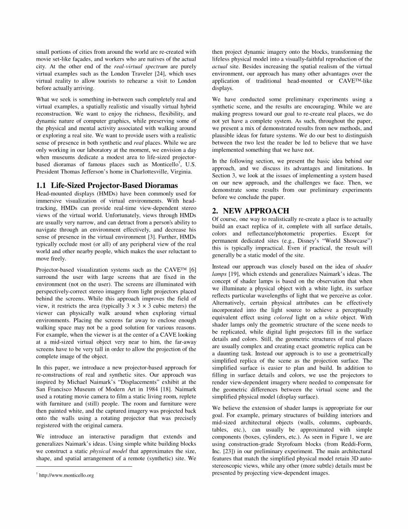
Figure 1. We use Styrofoam blocks to construct a geometrically simplified replica of the scene. The Styrofoam blocks are used as display surfaces on which view-dependent imagery of the scene is projected. Most of the geometric complexities in the scene, such as the window frames, windowsills, the pass-through in the middle wall, and the molding around it, are left out in the simplified replica. (This figure is reproduced in color on page 000.) Life-Sized Projector-Based Dioramas Kok-Lim Low Greg Welch Anselmo Lastra Henry Fuchs University of North Carolina at Chapel Hill Department of Computer Science, Campus Box 3175 Chapel Hill, NC 27599-3175, U.S.A. +1-919-962-1700 {lowk, welch, lastra, fuchs}@cs.unc.edu ABSTRACT We introduce an idea and some preliminary results for a new projector-based approach to re-creating real and imagined sites. Our goal is to achieve re-creations that are both visually and spatially realistic, providing a small number of relatively unencumbered users with a strong sense of immersion as they jointly walk around the virtual site. Rather than using head-mounted or general-purpose projector- based displays, our idea builds on previous projector-based work on spatially-augmented reality and shader lamps. Using simple white building blocks we construct a static physical model that approximates the size, shape, and spatial arrangement of the site. We then project dynamic imagery onto the blocks, transforming the lifeless physical model into a visually faithful reproduction of the actual site. Some advantages of this approach include wide field-of-view imagery, real walking around the site, reduced sensitivity to tracking errors, reduced sensitivity to system latency, auto-stereoscopic vision, the natural addition of augmented virtuality and the provision of haptics. In addition to describing the major challenges to (and limitations of) this vision, in this paper we describe some short-term solutions and practical methods, and we present some proof-of- concept results. Categories and Subject Descriptors I.3.7 [Computer Graphics]: Three-Dimensional Graphics and Realism – virtual reality; I.3.6 Methodology and Techniques – interaction techniques; I.3.8 Applications. Keywords Spatially-Augmented Reality, Virtual Reality, Augmented Virtuality, Virtual Environment, Shader Lamp, Diorama, Multiprojector Display System, Immersive Visualization, User Interface. 1. INTRODUCTION Many of us have fond memories of unusual places we have visited at one time or another, perhaps as adults, perhaps as children. The combination of sights, sounds, smells, and spatial experiences often leaves a lasting mental imprint. Museums and theme parks often try to evoke similar feelings by physically re- creating sites that are far away or perhaps lost with time. For example, Walt Disney World’s Epcot Center in Orlando, Florida (USA) includes a “World Showcase” area of the park where Permission to make digital or hard copies of all or part of this work for personal or classroom use is granted without fee provided that copies are not made or distributed for profit or commercial advantage and that copies bear this notice and the full citation on the first page. To copy otherwise, or republish, to post on servers or to redistribute to lists, requires prior specific permission and/or a fee. VRST’01, November 15-17, 2001, Banff, Alberta, Canada. Copyright 2001 ACM 1-58113-385-5/01/0011…$5.00.

Welcome message from author
This document is posted to help you gain knowledge. Please leave a comment to let me know what you think about it! Share it to your friends and learn new things together.
Transcript

Figure 1. We use Styrofoam blocks to construct a geometrically simplified replica of the scene. The Styrofoam blocks are used as display surfaces on which view-dependent imagery of the scene is projected. Most of the geometric complexities in the scene, such as the window frames, windowsills, the pass-through in the middle wall, and the molding around it, are left out in the simplified replica. (This figure is reproduced in color on page 000.)
Life-Sized Projector-Based Dioramas Kok-Lim Low Greg Welch Anselmo Lastra Henry Fuchs
University of North Carolina at Chapel Hill
Department of Computer Science, Campus Box 3175 Chapel Hill, NC 27599-3175, U.S.A.
+1-919-962-1700
{lowk, welch, lastra, fuchs}@cs.unc.edu
ABSTRACT We introduce an idea and some preliminary results for a new projector-based approach to re-creating real and imagined sites. Our goal is to achieve re-creations that are both visually and spatially realistic, providing a small number of relatively unencumbered users with a strong sense of immersion as they jointly walk around the virtual site.
Rather than using head-mounted or general-purpose projector-based displays, our idea builds on previous projector-based work on spatially-augmented reality and shader lamps. Using simple white building blocks we construct a static physical model that approximates the size, shape, and spatial arrangement of the site. We then project dynamic imagery onto the blocks, transforming the lifeless physical model into a visually faithful reproduction of the actual site. Some advantages of this approach include wide field-of-view imagery, real walking around the site, reduced sensitivity to tracking errors, reduced sensitivity to system latency, auto-stereoscopic vision, the natural addition of augmented virtuality and the provision of haptics.
In addition to describing the major challenges to (and limitations of) this vision, in this paper we describe some short-term solutions and practical methods, and we present some proof-of-concept results.
Categories and Subject Descriptors I.3.7 [Computer Graphics]: Three-Dimensional Graphics and Realism – virtual reality; I.3.6 Methodology and Techniques – interaction techniques; I.3.8 Applications.
Keywords Spatially-Augmented Reality, Virtual Reality, Augmented Virtuality, Virtual Environment, Shader Lamp, Diorama, Multiprojector Display System, Immersive Visualization, User Interface.
1. INTRODUCTION Many of us have fond memories of unusual places we have visited at one time or another, perhaps as adults, perhaps as children. The combination of sights, sounds, smells, and spatial experiences often leaves a lasting mental imprint. Museums and theme parks often try to evoke similar feelings by physically re-creating sites that are far away or perhaps lost with time. For example, Walt Disney World’s Epcot Center in Orlando, Florida (USA) includes a “World Showcase” area of the park where
Permission to make digital or hard copies of all or part of this work for personal or classroom use is granted without fee provided that copies are not made or distributed for profit or commercial advantage and that copies bear this notice and the full citation on the first page. To copy otherwise, or republish, to post on servers or to redistribute to lists, requires prior specific permission and/or a fee. VRST’01, November 15-17, 2001, Banff, Alberta, Canada. Copyright 2001 ACM 1-58113-385-5/01/0011…$5.00.
small�portions�of�cities�from�around�the�world�are�re-created�with�movie�set-like�façades,�and�workers�who�are�natives�of�the�actual�city.� At� the� other� end� of� the� real-virtual� spectrum� are� purely�virtual� examples� such� as� the� London� Traveler� [24],� which�uses�virtual� reality� to� allow� tourists� to� rehearse� a� visit� to� London�before�actually�arriving.�
What�we�seek�is�something�in-between�such�completely�real�and�virtual� examples,� a�spatially�realistic�and�visually�virtual�hybrid�reconstruction.� We� want� to� enjoy� the� richness,� flexibility,� and�dynamic�nature�of� computer�graphics,�while�preserving� some�of�the�physical� and�mental�activity�associated�with�walking�around�or�exploring�a�real�site.�We�want�to�provide�users�with�a�realistic�sense�of�presence�in�both�synthetic�and�real�places.�While�we�are�only�working�in�our�laboratory�at�the�moment,�we�envision�a�day�when� museums� dedicate� a� modest� area� to� life-sized� projector-based� dioramas� of� famous� places� such� as� Monticello†,� U.S.�President�Thomas�Jefferson’s�home�in�Charlottesville,�Virginia.�
1.1� Life-Sized�Projector-Based�Dioramas�Head-mounted� displays� (HMDs)� have� been� commonly� used� for�immersive� visualization� of� virtual� environments.� With� head-tracking,� HMDs� can� provide� real-time� view-dependent� stereo�views�of� the�virtual�world.�Unfortunately,�views�through�HMDs�are�usually�very�narrow,�and�can�detract�from�a�person's�ability�to�navigate� through� an� environment� effectively,� and� decrease� his�sense�of�presence�in�the�virtual�environment�[3].�Further,�HMDs�typically�occlude�most�(or�all)�of�any�peripheral�view�of�the�real�world�and�other�nearby�people,�which�makes�the�user�reluctant�to�move�freely.�
Projector-based� visualization� systems� such� as� the� CAVE™� [6]�surround� the� user� with� large� screens� that� are� fixed� in� the�environment�(not�on�the�user).�The�screens�are� illuminated�with�perspectively-correct�stereo�imagery�from�light�projectors�placed�behind� the� screens.� While� this� approach� improves� the� field� of�view,� it� restricts� the� area� (typically�3�×�3�×�3�cubic�meters)� the�viewer� can� physically� walk� around� when� exploring� virtual�environments.� Placing� the� screens� far� away� to� enclose� enough�walking� space� may� not� be� a� good� solution� for� various� reasons.�For�example,�when�the�viewer�is�at�the�center�of�a�CAVE�looking�at� a� mid-sized� virtual� object� very� near� to� him,� the� far-away�screens�have�to�be�very�tall�in�order�to�allow�the�projection�of�the�complete�image�of�the�object.�
In� this� paper,� we� introduce� a� new� projector-based� approach� for�re-constructions� of� real� and� synthetic� sites.� Our� approach� was�inspired� by� Michael� Naimark’s� “Displacements”� exhibit� at� the�San� Francisco� Museum� of� Modern� Art� in� 1984� [18].� Naimark�used�a�rotating�movie�camera�to�film�a�static�living�room,�replete�with� furniture� and� (still)� people.� The� room� and� furniture� were�then�painted�white,�and�the�captured�imagery�was�projected�back�onto� the� walls� using� a� rotating� projector� that� was� precisely�registered�with�the�original�camera.�
We� introduce� an� interactive� paradigm� that� extends� and�generalizes�Naimark’s�ideas.�Using�simple�white�building�blocks�we�construct� a� static�physical�model� that�approximates� the�size,�shape,� and� spatial� arrangement�of� a� remote� (synthetic)� site.�We��������������������������������������������������������������†�http://www.monticello.org�
then� project� dynamic� imagery� onto� the�blocks,� transforming� the�lifeless�physical�model�into�a�visually-faithful�reproduction�of�the�actual� site.�Besides� increasing� the� spatial� realism�of� the�virtual�environment,� our� approach� has� many� other� advantages� over� the�application� of� traditional� head-mounted� or� CAVE™-like�displays.�
We� have� conducted� some� preliminary� experiments� using� a�synthetic� scene,� and� the� results� are� encouraging.� While� we� are�making�progress� toward�our�goal� to�re-create�real�places,�we�do�not�yet�have�a� complete� system.�As� such,� throughout� the�paper,�we�present�a�mix�of�demonstrated�results�from�new�methods,�and�plausible� ideas�for�future�systems.�We�do�our�best�to�distinguish�between� the� two� lest� the� reader� be� led� to� believe� that�we�have�implemented�something�that�we�have�not.�
In� the� following� section,� we� present� the� basic� idea� behind� our�approach,� and� we� discuss� its� advantages� and� limitations.� In�Section�3,�we�look�at�the�issues�of�implementing�a�system�based�on� our� new� approach,� and� the� challenges� we� face.� Then,� we�demonstrate� some� results� from� our� preliminary� experiments�before�we�conclude�the�paper.�
2.� NEW�APPROACH�Of�course,�one�way�to�realistically�re-create�a�place�is�to�actually�build� an� exact� replica� of� it,� complete� with� all� surface� details,�colors� and� reflectance/photometric� properties.� Except� for�permanent� dedicated� sites� (e.g.,� Disney’s� “World� Showcase”)�this� is� typically� impractical.� Even� if� practical,� the� result� will�generally�be�a�static�model�of�the�site.��
Instead� our� approach� was� closely� based� on� the� idea� of� shader�lamps�[19],�which�extends�and�generalizes�Naimark’s�ideas.�The�concept� of� shader� lamps� is� based� on� the� observation� that� when�we� illuminate� a� physical� object� with� a� white� light,� its� surface�reflects�particular�wavelengths�of�light�that�we�perceive�as�color.�Alternatively,� certain� physical� attributes� can� be� effectively�incorporated� into� the� light� source� to� achieve� a� perceptually�equivalent� effect� using� colored� light� on� a� white� object.� With�shader� lamps�only� the�geometric� structure�of� the�scene�needs�to�be� replicated,� while� digital� light� projectors� fill� in� the� surface�details� and� colors.� Still,� the� geometric� structures� of� real� places�are�usually�complex�and�creating�exact�geometric�replica�can�be�a� daunting� task.� Instead� our� approach� is� to� use� a� geometrically�simplified� replica� of� the� scene� as� the� projection� surface.� The�simplified� surface� is� easier� to� plan� and� build.� In� addition� to�filling� in� surface� details� and� colors,� we� use� the� projectors� to�render�view-dependent� imagery�where�needed�to�compensate�for�the� geometric� differences� between� the� virtual� scene� and� the�simplified�physical�model�(display�surface).�
We�believe�the�extension�of�shader� lamps�is�appropriate�for�our�goal.� For� example,� primary� structures� of� building� interiors� and�mid-sized� architectural� objects� (walls,� columns,� cupboards,�tables,� etc.),� can� usually� be� approximated� with� simple�components�(boxes,�cylinders,�etc.).�As�seen�in�Figure�1,�we�are�using� construction-grade� Styrofoam� blocks� (from� Reddi-Form,�Inc.�[23])� in�our�preliminary�experiment.�The�main�architectural�features�that�match�the�simplified�physical�model�retain�3D�auto-stereoscopic�views,�while�any�other�(more�subtle)�details�must�be�presented�by�projecting�view-dependent�images.�

In� general,� different� degrees� of� approximation� of� the� scene�geometry�produce�a�spectrum�of�display�surfaces�that�range�from�single� flat� screens� (a� CAVE™)� to� display� surfaces� that� exactly�match�the�scene�geometry.�For�our�goal,�we�want�to�simplify�the�display�surfaces�as�much�as�possible�but�still�preserve�the�empty�space� where� the� user� may� walk,� bend� over,� or� put� his� arm�through,� for� instance.�However,� in�Section�2.1,�we�will�see� that�there� are� many� advantages� to� having� the� display� surfaces� as�similar�as�possible�to�the�scene�geometry.�
2.1� Advantages�Although�the�initial�motivation�is�to�provide�more�spatial�realism�to�the�user,�our�approach�has�many�other�advantages�that�are�also�essential� for� achieving�our�goal�of�re-creating�real�places.�Some�of�these�advantages�are�listed�below.�
2.1.1� Wide�FOV�and�Peripheral�Vision�Human� vision� has� an� effective� field� of� view� (FOV)� that� spans�approximately� 200� degrees� horizontally� by� 150� degrees�vertically.� Many� commercially� available� HMDs� have� relatively�narrow� fields� of� view,� ranging� from� roughly� 30� to� 70� degrees�diagonally.� A� narrow� FOV� has� been� shown� (in� real�environments)� to� degrade� human� performance� on� navigation,�manipulation,� spatial� awareness,� and�visual�search�tasks,�and�to�disrupt� our� eye-� and� head-movement� coordination� and� our�perception�of�size�and�space�[8][2][3].�Peripheral�vision�is�known�to� be� well-suited� to� maintaining� self-orientation� during�locomotion� [14],� and� there� is� evidence� to� suggest� that� a�narrow�field�of�view�detracts�from�a�person's�ability�to�navigate�through�an�environment� effectively,� and�decreases�his� sense�of�presence�in�the�virtual�environment.�
One� of� the� main� motivations� of� the� CAVE� system� and� our�approach�is�to�provide�visualization�with�a�very�wide�FOV.�This�is� done� by� using� large� projection� screens� that� are� fixed� in� the�environment�at�some�distance�from�the�user.�Doing�this�also�has�other�advantages�over�HMDs—the�user�no�longer�needs�to�wear�heavy�gear�on�his�head,�and�fast�head�rotations�are�less�likely�to�produce�serious�swimming�effects�[6].�
2.1.2� Real�Walking�With� our� approach,� the� physical� arrangement� of� the� display�surfaces� allows� the� user� to� really� walk� around� in� the� virtual�environment.�Real�walking�gives�stronger�sense�of�presence�than�walking-in-place� and� virtual� flying� [27],� but� at� the� expense� of�larger�physical�space.�
With� systems� such� as� CAVE,� the� virtual� environment� that� the�user� explores� can�be� larger� than� the�enclosed�physical�space.�In�such� a� situation� however,� users� can� only� navigate� using� less�natural� methods� such� as� walking-in-place� or� pressed-button�virtual�flying.�
2.1.3� Reduced�Sensitivity�to�Tracking�Error�Like� general-purpose� projector-based� setups� such� as� the�CAVE™,�where� the�display� surface� is�fixed�in� the�environment�rather�than�to�the�user�(as�in�a�HMD),�our�approach�is�relatively�insensitive� to� error� in�estimates�of� the�head�orientation.�See�[6]�for� a� complete� explanation.� However� unlike� general-purpose�
projector-based� systems,� our� approach� is� also� relatively�insensitive�to�error�in�estimates�of�the�head�position.�
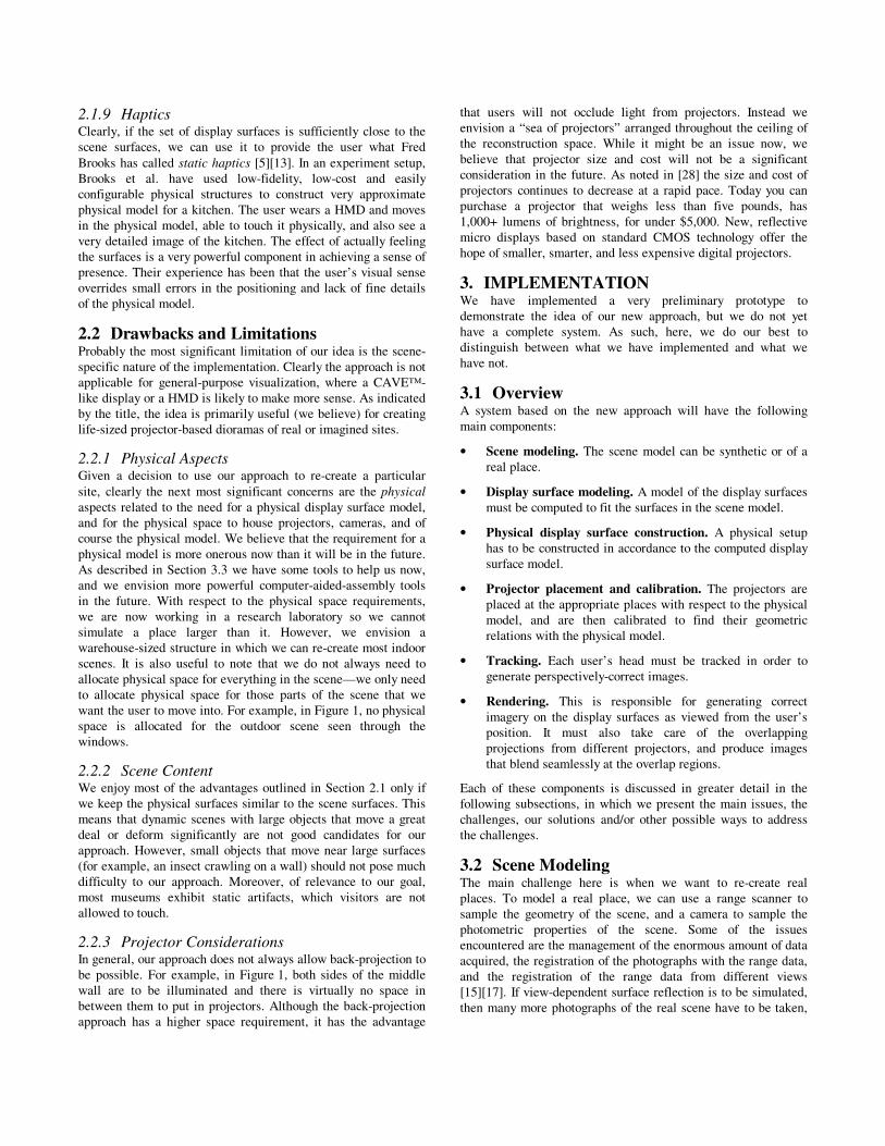
The� diagram� in� Figure�2� illustrates� the� geometry� of� a� general�projector-based� setup� from� a� top� view.� This� will� be� used� to�illustrate�error�in�a�horizontal�plane.�The�vertical�error�would�be�similarly� derived.� The� point� V� represents� some� point� on� the�graphics�model,� i.e.�a�point�on�the�virtual�surface.�If� the� tracker�reports� the�viewpoint� is� at�E1,� the� subsequently� rendered� image�of�point�V�will�appear�on�the�physical�display�surface�at�point�D1.�However�if�the�eye�point�is�actually�located�at�point�E2,�then�the�image� of� point� V� should� have� been� rendered� on� the� display�surface� at� point� D2.� As� a� result,� the� user� will� experience� an�angular�viewing�error�of�θE.��
Note� that� the� shape�of� the�display� surface�is� irrelevant;�because�the� point� D2� is� not� being� rendered,� it� does� not� matter� where� it�should� appear� (anywhere� on� the� line� VE2),� the� user� will� still�experience�the�same�error,�θE.�Similarly� the�absolute�position�of�the�eye�point�is�not�the�critical�factor,�what�matters�is�the�relative�position�of�the�actual�eye�point�with�respect�to�the�rendered�point�D1.�
In� fact,� the� angular� error� θE� depends� only� on� three� parameters:�VE2,� the� distance� from� the� virtual� scene�point� to� the�user’ s� eye�point;� VD1,� the� distance� from� the� virtual� scene� point� to� the�physical�display�surface;�and�θV,�the�angle�between�the�estimated�and� actual� eye� points.� Given� those� three� parameters� and� some�trigonometric�manipulation,� the�angular�viewing�error�θE�can�be�computed�as�
( ) ���
�
�
���
�
�
++=
V
VE
VEVDVEVD
VD
θ
θθ
cos2
)sin(asin
212
22
1
1 �
The� two� surface�plots� in�Figure�3� illustrate� the� angular�viewing�error�θE�throughout�a�space�approximately�the�size�of�a�CAVE™,�for�display� surface�distances�VD1� from�a�virtual�point� at� the�far�corner�of�the�plot�(0,�0)�of�10�and�50�cm.�To�cover�the�space,�θV�is�varied�from�0�to�approximately�90�degrees,�and�VE2� is�varied�between�0�and�2�meters.�
Note�from�the�above�equation�and�plots�that�the�angular�error�(a)�increases� as� the� angle�θV� between� the� estimated�and�actual� eye�points� increases,� (b)� decreases� as� the� distance� VE2� from� the�virtual� scene� point� to� the� actual� view� point� increases,� and� (c)�
virtual�surface�
display�surface�D1�D2�
E1�E2�
θV�
θE�
V�
Figure�2��

�
�Figure�3�
increases� as� the� distance� VD1� between� the� real� and� virtual�surface� increases.�The� first� and� second�cases� are� likely�familiar�to�most�people�who�have�experience�with�conventional�computer�graphics�and�perspective�projection.�However�the�last�case�is�less�frequently� recognized� or� discussed� in� conventional� computer�graphics,�most� likely�because�the�display�surface�and�the�virtual�objects�are�typically�very�different.�The�important�thing�to�note�is�that� even� if� the� display� surface� is� not� precisely� located� and�shaped�like�the�corresponding�virtual�portion�of�the�scene,�if�it�is�relatively� close,� and� if� the� viewer� does� not� get� too� close� to� the�display�surface,�the�angular�error�can�be�relatively�small.�
Note� that� if�VD1�=�0,� i.e.� if� the�physical�display� surface�exactly�matches�the�corresponding�virtual�objects,�then�the�angular�error�θE� is�0�no�matter�what�the�values�of�VE2�and�θV.�In�other�words,�in�that�special�case�you�would�not�even�need�a�tracking�system—you� would� simply� “ paint” � the� display� surface� with� the� proper�colors.�
2.1.4� Reduced�Sensitivity�to�Latency�The� sensitivity� to� view� position� error� with� HMDs� and� general-purpose� projector-based� displays� magnifies� the� effect� of�unavoidable� latencies� in� the� graphics� pipeline.� The� problem� is�that�the�scene�ends�up�being�rendered�from�the�wrong�viewpoint:�from�where�the�user�was,� rather� than�where�he�actually�is.�Such�
latency-induced� viewing� errors� can� break� a� user’ s� sense� of�presence�or�immersion,�and�can�even�cause�motion�sickness.�
In� contrast,� because� our� scene-specific� approach�enjoys� reduced�sensitivity� to� tracker� error,� it� consequently� also� enjoys� reduced�sensitivity� to� system� latencies.� People� typically� translate� their�heads�relatively�slowly,�and�even�fast�head�rotations�cause�only�a�relatively�small�change�in�the�eye�positions.�
The� effect� of� reduced� sensitivity� to� latency� can� be� readily�observed� in� our� prototype� system,� where� system� latencies� are�quite� noticeable� for� the� outdoor� views� through� the� window�(where� VD1� is� quite� large),� but� are� much� less�noticeable� at� the�windowsills� and� the� molding� around� the� pass-through� (where�VD1�is�relatively�small).�
2.1.5� Natural�Auto-Stereoscopic�Vision�When� the� geometry� of� the� display� surfaces� matches� that� of� the�virtual� environment� exactly,� the� images� of� the� scene� projected�onto� the� display� surfaces� are�naturally�3D�stereoscopic,�without�the�use�of�any�special�3D�stereo�projection.�After�all,�the�user�is�viewing�the�actual�3D�surfaces.�When�the�set�of�display�surfaces�is� a� simplified� model� of� the� scene,� only� parts� of� the� scene� that�match� the� display� surfaces� will� retain� auto-stereoscopic� views,�and� other� parts� must� be� reproduced� using� special� 3D� stereo�projection.� In� our� preliminary� experiment,� we� have� many� large�walls� in� the� scene� that� match� the� simplified� display� surfaces.�Even�without� the�use�of� stereo�projection,� the�virtual�scene�still�looks� three-dimensional� because� most� of� the� surfaces� are� very�close�to�the�actual�desired�geometry.�
2.1.6� High�Spatial�and�Geometric�Fidelity�In� traditional� graphics� rendering,� spatial� and� geometric�properties�of� an�object� are�presented�in� images.�The�resolutions�of� these�images�can�limit�the�accuracy�with�which�the�geometric�properties� are�presented.�However,� using�our� approach,�parts�of�the�scene�model�that�match�the�display�surfaces’ �geometry�can�be�presented� with� very� high� spatial� and� geometric� fidelity� [19]—after� all,� aside� from� color,� the� user� is� viewing� a� real� physical�object.�
2.1.7� Eye�Accommodation�As�mentioned�by�Cruz-Neira�[6],�eye�accommodation�(eye�focus)�provides� depth� cues� in� the� real� world.� In� typical� computer�graphics,�HMD�VR�and�CAVE,�eye�accommodation�has�not�been�incorporated� in� visualization,� and� everything� in� the� virtual�environments�is�in�focus.�With�our�approach�and�the�approach�of�the�shader� lamps,� the�user�can�now�selectively�focus�his�eyes�on�any�part�of�the�scene,�thus�providing�the�user�a�very�natural�way�to�visualize�the�virtual�environment.�
2.1.8� Augmented�Virtuality�Because� the� physical� arrangement� of� the� display� surfaces� is�spatially� similar� to� that� geometry� of� the� scene,� it� is� relatively�easy�to�add�real�objects�to�the�virtual�environment.�For�example,�if�a�set�of�display�surfaces�approximates�a�virtual�desk,� then�we�can� put� a� vase� on� the�desk�by�placing�a� real�vase�on� the� set�of�display� surfaces� that� approximates� the� desk.� Additional�projectors� can� then� be� used� to� properly� light� up� the� added� real�object� to� simulate� the� effect� of� the� virtual� lights� in� the� virtual�environments.�
2.1.9� Haptics�Clearly,� if� the� set�of�display� surfaces� is� sufficiently� close� to� the�scene� surfaces,� we� can� use� it� to� provide� the� user� what� Fred�Brooks�has�called�static�haptics�[5][13].�In�an�experiment�setup,�Brooks� et� al.� have� used� low-fidelity,� low-cost� and� easily�configurable� physical� structures� to� construct� very� approximate�physical�model�for�a�kitchen.�The�user�wears�a�HMD�and�moves�in� the�physical�model,�able� to� touch�it�physically,�and�also�see�a�very�detailed�image�of� the�kitchen.�The�effect�of�actually�feeling�the�surfaces�is�a�very�powerful�component�in�achieving�a�sense�of�presence.�Their�experience�has�been�that� the�user’ s�visual�sense�overrides� small� errors� in� the�positioning�and�lack�of�fine�details�of�the�physical�model.�
2.2� Drawbacks�and�Limitations�Probably�the�most�significant�limitation�of�our�idea�is�the�scene-specific�nature�of�the�implementation.�Clearly�the�approach�is�not�applicable� for� general-purpose� visualization,� where� a� CAVE™-like�display�or�a�HMD�is�likely�to�make�more�sense.�As�indicated�by�the�title,�the�idea�is�primarily�useful�(we�believe)�for�creating�life-sized�projector-based�dioramas�of�real�or�imagined�sites.�
2.2.1� Physical�Aspects�Given� a� decision� to� use� our� approach� to� re-create� a� particular�site,� clearly� the� next� most� significant� concerns� are� the�physical�aspects�related�to� the�need�for�a�physical�display�surface�model,�and� for� the� physical� space� to� house� projectors,� cameras,� and�of�course�the�physical�model.�We�believe�that�the�requirement�for�a�physical�model�is�more�onerous�now�than�it�will�be�in�the�future.�As�described�in�Section�3.3�we�have�some�tools�to�help�us�now,�and� we� envision� more� powerful� computer-aided-assembly� tools�in� the� future.� With� respect� to� the� physical� space� requirements,�we� are� now� working� in� a� research� laboratory� so� we� cannot�simulate� a� place� larger� than� it.� However,� we� envision� a�warehouse-sized�structure�in�which�we�can�re-create�most�indoor�scenes.� It� is� also� useful� to� note� that� we� do� not� always� need� to�allocate�physical�space�for�everything�in�the�scene— we�only�need�to� allocate� physical� space� for� those� parts� of� the� scene� that� we�want�the�user�to�move�into.�For�example,�in�Figure�1,�no�physical�space� is� allocated� for� the� outdoor� scene� seen� through� the�windows.�
2.2.2� Scene�Content�We�enjoy�most�of� the�advantages�outlined�in�Section�2.1�only�if�we�keep�the�physical�surfaces�similar�to�the�scene�surfaces.�This�means� that�dynamic� scenes�with� large�objects� that�move�a�great�deal� or� deform� significantly� are� not� good� candidates� for� our�approach.�However,� small�objects� that�move�near� large�surfaces�(for�example,�an�insect�crawling�on�a�wall)�should�not�pose�much�difficulty� to� our� approach.� Moreover,� of� relevance� to� our� goal,�most� museums� exhibit� static� artifacts,� which� visitors� are� not�allowed�to�touch.�
2.2.3� Projector�Considerations�In�general,�our�approach�does�not�always�allow�back-projection�to�be� possible.� For� example,� in�Figure�1,�both� sides�of� the�middle�wall� are� to� be� illuminated� and� there� is� virtually� no� space� in�between�them�to�put� in�projectors.�Although�the�back-projection�approach� has� a� higher� space� requirement,� it� has� the� advantage�
that� users� will� not� occlude� light� from� projectors.� Instead� we�envision�a� “ sea�of�projectors” �arranged�throughout�the�ceiling�of�the� reconstruction� space.� While� it� might� be� an� issue� now,� we�believe� that� projector� size� and� cost� will� not� be� a� significant�consideration�in� the�future.�As�noted�in�[28]�the�size�and�cost�of�projectors� continues� to�decrease� at� a� rapid�pace.�Today�you�can�purchase� a� projector� that� weighs� less� than� five� pounds,� has�1,000+� lumens� of� brightness,� for� under�$5,000.�New,� reflective�micro� displays� based� on� standard� CMOS� technology� offer� the�hope�of�smaller,�smarter,�and�less�expensive�digital�projectors.�
3.� IMPLEMENTATION�We� have� implemented� a� very� preliminary� prototype� to�demonstrate� the� idea� of� our� new� approach,� but� we� do� not� yet�have� a� complete� system.� As� such,� here,� we� do� our� best� to�distinguish� between� what� we� have� implemented� and� what� we�have�not.�
3.1� Overview�A� system� based� on� the� new� approach� will� have� the� following�main�components:�
• Scene�modeling.�The� scene�model�can�be�synthetic�or�of�a�real�place.�
• Display�surface�modeling.�A�model�of�the�display�surfaces�must�be�computed�to�fit�the�surfaces�in�the�scene�model.�
• Physical� display� surface� construction.� A� physical� setup�has�to�be�constructed�in�accordance�to�the�computed�display�surface�model.�
• Projector� placement� and� calibration.� The� projectors� are�placed�at�the�appropriate�places�with�respect�to�the�physical�model,� and� are� then� calibrated� to� find� their� geometric�relations�with�the�physical�model.�
• Tracking.� Each� user’ s� head� must� be� tracked� in� order� to�generate�perspectively-correct�images.�
• Rendering.� This� is� responsible� for� generating� correct�imagery� on� the� display� surfaces� as� viewed� from� the�user’ s�position.� It� must� also� take� care� of� the� overlapping�projections� from� different� projectors,� and� produce� images�that�blend�seamlessly�at�the�overlap�regions.�
Each� of� these� components� is� discussed� in� greater� detail� in� the�following� subsections,� in�which�we�present� the�main�issues,� the�challenges,� our� solutions� and/or� other� possible� ways� to� address�the�challenges.��
3.2� Scene�Modeling�The� main� challenge� here� is� when� we� want� to� re-create� real�places.� To� model� a� real� place,� we� can� use� a� range� scanner� to�sample� the� geometry� of� the� scene,� and� a� camera� to� sample� the�photometric� properties� of� the� scene.� Some� of� the� issues�encountered�are�the�management�of�the�enormous�amount�of�data�acquired,�the�registration�of�the�photographs�with�the�range�data,�and� the� registration� of� the� range� data� from� different� views�[15][17].�If�view-dependent�surface�reflection�is�to�be�simulated,�then�many�more�photographs�of� the�real�scene�have�to�be�taken,�

and� a� light-field� approach� can� be� used� to� render� the� view-dependent�images�[29].�
Currently,� the� most� practical� interactive� rendering� method� for�VR� is� still� the� traditional� polygon-based� z-buffer� approach.�Therefore,� surface� reconstruction� from� range� data� to� generate� a�polygonal� model� [7]� is� necessary.� Mesh� simplification� [11]� is�then� applied� to� reduce� the� number� of� polygons� by� eliminating�redundant�geometric�information.�During�rendering,�photographs�of�the�real�scene�can�then�be�textured�onto�the�simplified�mesh.�
While�we�currently�only�demonstrate�our� ideas�with� a� synthetic�scene,�we�have�collected�and�are�in�the�process�of�preparing�very�high-quality� image-based� models� of� the� Monticello� library.� We�acquired� the�models�using�a�3rdTech� [1]� laser� scanner�during�a�multi-day� trip� to� Monticello� with� our� UVA� collaborator� David�Luebke.�
3.3� Display�Surface�Modeling�and�Construction�The�need�to�model�and�build�non-trivial�physical�display�surfaces�is�a�challenge�not�seen�in�other�projector-based�approaches.�One�of�our�main�objectives�is�that�the�physical�display�surfaces�should�be�easy�to�setup.�This�has� led�us� to�consider�Lego™-like�blocks�from�a�set�of�predefined�simple�shapes.�An�open�question�is�what�is�the�best�general�set�of�predefined�shapes?�
With�a�selected�set�of�predefined�shapes,�we�would�like�to�have�a�method�to�automatically�compute�an�arrangement�of�the�blocks�to�best� fit� the� surfaces�of� the� scene�model.�This� is� a�very�difficult�problem,� and� we� do� not� see� any� similar� problems� in� the�literature.�
In� our� prototype,� we� use� 0.25� � 1.2� � 0.3� cubic� meters� white�stackable� Styrofoam� blocks� to� set� up� the� physical� display�surfaces.�To�create�a�display�surface�model� in� the�computer,�we�have� implemented�a�program�to�allow�us� to�manually�design�an�arrangement�of� the�blocks� to� fit� the�scene�model.�This�model� is�then�used�as�the�blueprint�to�roughly�construct�the�physical�setup.�Later� when� the� projectors� are� calibrated,� we� project� wireframe�images�of� the�display� surface�model�onto� the�physical�blocks�to�help�us�fine-tune�and�correct�the�physical�setup.�
In� the�future�we�envision�using�the�projectors�and�the�analytical�models� of� the� display� surface� to�guide�users� in� the� assembly�of�the� physical� model.� Given� an� empty� space� with� calibrated�projectors,� an� automated� program� could� render� the� outline� of� a�block� on� the� floor,� waiting� for� the� assembly� worker� to� confirm�placement� of� the� block.� Similar� steps� are� applied� to� the�remaining�blocks,�including�stacked�blocks.�
3.4� Projector�Placement�and�Calibration�3.4.1� Projector�Placement�After� the� display-surface� model� has� been� created,� we� need� to�decide�where�we�want�to�place�the�projectors.�We�may�also�want�to� know� the�minimum�number�we�need� to� cover� all� the�display�surfaces.�This�problem�is�similar�to�that�of�the�camera�placement�in�image-based�modeling�[9][25],�but�it�is�made�more�difficult�by�the�fact�that,�besides�their�positions,�we�also�want�to�compute�the�projectors’ �orientations.�
A� method� to� compute� a� good� set� of� projectors’ � positions� and�orientations�would�want�to�take�into�consideration�the�following:�
• physical� and� environmental� constraints� on� the� projector�mounting,�
• maximizing�the�area�of�coverage�of�each�projector,�
• minimizing�overlap�area,�
• maintaining�a�certain�image�resolution�on�display�surfaces,�
• minimizing�possible�occlusion�by�the�user,�
• minimizing�inter-reflections�among�display�surfaces,�and�
• minimizing�the�number�of�projectors.�
In�order� to�minimize�inter-reflections�of� light,� it� is�best� to�avoid�projecting�light�on�a�large�surface�at�a�very�oblique�angle.�
We� have� not� yet� automated� the� projector� placement.�This� is� an�open�area�of�research.�Currently�we�mount� the�projectors�(using�flexible� brackets)� in� places� that� we� believe� accommodate� the�above� considerations,� then� typically� try� a� few� variations� before�settling�on�the�final�pose.�
3.4.2� Projector�Calibration�After� the� projectors� are� positioned� and� oriented� appropriately�with� respect� to� the� physical� display� surfaces,� we� adjust� their�focusing� distances� to�get� the�best� focus�on� the�display� surfaces.�The�next�step�is�to�calibrate�the�projectors�to�find�their�geometric�relations�with�the�scene�model�and�the�display�surface�model.�
To� calibrate� a� projector,� we� need� to� find� a� set� of� pair-correspondences.� Each� pair-correspondence� consists� of� the�coordinates� of� a� 3D� point� in� space,� and� its� corresponding�pixel�coordinates�on�the�projector’ s� image�plane.�With�sufficient�pair-correspondences� (at� least� six,� and� no� four� 3D� points� are�coplanar),�we�can�solve�for�the�projection�parameters�using�linear�least-square�methods�or�nonlinear�optimization�approaches�[10].�To�find�a�pair�correspondence,�we�project�a�known�2D�point�from�the�projector,�which�emerges� from� the�projector� as� a� ray.�Then,�we� move� a� small�display� surface� to� intersect� the� ray,� and�use� a�tracker� to�measure�the�3D�position�of�the�intersection.�These�3D�points� are� then� transformed� from� the� tracker� coordinate� system�into� the� coordinate� system� of� the� scene� model,� using� a� known�transformation.�This�set�of�pair-correspondences�is�used�to�solve�for� the� projector’ s� projection� parameters� with� respect� to� the�scene’ s�coordinate�system.�
The�above�manual�approach�to�finding�pair-correspondences�can�be� tedious� and� error-prone� at� times.� In� the� future,� automatic�projector� calibration� using� cameras� such� as� in� [22]� might� be�implemented,� possibly� as� part� of� an� automated� projector-placement�algorithm.�
3.5� Tracking�Since� the� user� is� allowed� to� freely� walk� around� within� a�potentially� large� area,� we� need� a� wide-area� tracking� device� to�track� his� head� position.� If� the� user’ s� limbs� are� also� allowed� to�interact�with� the� environment,� then�they�need�to�be�tracked�too.�The� required� spatial� resolution� and� accuracy� depend� largely� on�the� largest� VD1� in� the� model� (see� Figure�2).� The� larger� the�distances� between� the� desired� model� and� the� physical� display�surfaces,� the�more� important� the� spatial� fidelity�of� each� tracked�view.�

We� use� two� 3rdTech’ s� [1]� HiBall� trackers� in� our� experiment.�These� trackers� can�cover� a�very�wide�area�and�have�sufficiently�high�precision�and� low� latency.�One�tracker� is�used�to� track�the�user’ s� head� and�another� is� tracking� the�position�and�orientation�of� a�virtual� spray�can.�Each�position� returned�by� the� trackers� is�transformed�into�the�coordinate�system�of�the�scene�model.�
3.6� Rendering�3.6.1� Generating�Perspectively-Correct�Images�For� each� projector,� we� use� a� two-pass� rendering� approach� to�generate� the� correct� images� for� the� user.� In� the� first� pass,� the�scene�model�is�rendered�normally�from�the�position�of�the�user’ s�eye.�The�resulting�image�is�read�back�from�the�framebuffer,�to�be�used� in� the� next� pass.� In� the� second� pass,� the� display� surface�model� is� rendered� from� the� projector’ s� viewpoint,� with� the�display� surfaces� texture-mapped� with� the� image� created� in� the�first� pass.�The� texture�map� is�mapped�onto� the�display�surfaces�using�projective� texture�mapping,�projected�from�the�position�of�the� user’ s� eye� [21].� The� image� read-back� from� the� framebuffer�can� be� a� performance� bottleneck� because� transferring� the� high-resolution� image� can� be� very� demanding� on� the� memory�bandwidth�of�many�rendering�systems.�
3.6.2� Display�Surface�Partitioning�To� provide� a� panoramic� view� to� the� user,� we� have� to� project�images�on�all� the�display�surfaces�around�the�user.�Consider�the�situation� in� Figure�4:� two� walls� are� illuminated� by� a� projector�and� the� user� is� in� between� the� two� walls.� During� the� first�rendering�pass,�we�need�to�render�an�image�of�the�scene�from�the�viewer’ s�position.�However,�there�is�no�way�we�can�set�up�a�view�frustum�that�can�generate�a�complete� image�of� the� two�walls.�In�order� to�generate� complete� images�of� the� two�walls,�we�can� set�up� two� different� view� frusta,� each� one� looking� at� a� wall,� and�render�two�images.�During�the�second�rendering�pass,�the�display�surfaces�that�approximate�each�wall�are�texture�mapped�with�the�corresponding� image�created�in� the�first�pass.�This�requires� that�the�display�surfaces�be�separated�into�groups�so�that�each�group�can�be� texture�mapped�with�a�different� image.�In�our�prototype,�we�have�partitioned�the�display�surfaces�manually.�
3.6.3� Seamless�Blending�of�Projections�Regions� of� the� display� surface� that� are� illuminated� by� multiple�projectors� appear� brighter,� making� the� overlap� regions� very�noticeable� to� the� user.� To� make� the� overlap� regions� appear�seamless,� we� can� use� alpha� blending� techniques� to� reduce� the�intensity�of�each�projector’ s�projection�in�the�overlap�region�[22].�However,�our�display�surfaces�can�have�concave�regions�that�can�cause� the� overlap� regions,� as� seen� from� a� projector,� to� be� non-
contiguous.� Traditional� intensity� roll-off� method� cannot� handle�this�case�very�well,�but�there�is�a�better�method�proposed�in�[19].�
Another�problem�of�merging� images� from�multiple�projectors� is�the� lack� of� color� equivalence� between� neighboring� projectors�[16].� Majumder� et� al.� use� hardware� color� look-up� tables� to�correct�for�the�color�mismatch�between�projectors.�
We�have�not�implemented�any�correction�for�overlap�regions�and�color�differences�in�our�prototype�system.�
3.7� Other�Issues�and�Challenges�3.7.1� Inter-Reflections�From�our�preliminary�experiments,�we�have�observed�that�inter-reflections�of�light�from�the�projectors�can�be�a�serious�problem.�They� degrade� the� quality� of� the� projected� images� by� reducing�their� contrast� and� color� saturation.� We� do� not� yet� have� a� good�solution�to�this�problem,�but�we�believe�the�following�guidelines�are�helpful:�
• use�less�reflective�(more�diffuse)�display�surface�material,�
• avoid�overly�oblique�projections�on�large�surfaces.�
In� the� future� we� envision�an�automated�approach� that� takes� the�latter�(and�other�heuristics)�into�account.�
3.7.2� Shadows�One� major� problem� of� using� front-projection� approach� for� our�purpose� is� that� the�projectors�may�be�occluded�by�the�user.�Our�experience�with�our�prototype�has�been�that� the�shadows�can�be�quite�annoying.�We�can�place�the�projectors�higher�and�closer�to�the�display� surfaces,�but� this� is�not� a�good� solution�because�the�projectors�will�be�at�very�oblique�angles� to� the�display�surfaces.�A� possible� solution� is� to� have� at� least� a� “ backup” �projector� for�every�projector,�and�a�projector�and�its�“ backups” �will�illuminate�the� same� surface� from� different� locations� but� not� at� the� same�time.� Video� cameras� and� trackers� are� used� to� determine� which�projectors�the�user�has�occluded�and�the�“ backups” �will�be�called�in�to�fill�in�the�shadows.�
3.7.3� Multiple�Viewers�If�the�physical�display�surfaces�match�the�virtual�scene�geometry,�then�multiple�viewers�should�be�able�to�explore�the�environment�simultaneously,�and�everyone�will�always�see�the�correct�images,�without� the� need� for� tracking.� (See� “ Reduced� Sensitivity� to�Tracking� Error” � in� Section� 2.1.3.)� However� this� extreme�requirement�for�the�physical�model�is�unrealistic�or�unreasonable�to�expect�for�most�situations�we�can�imagine.�This�means�that�the�need�to�support�multiple�simultaneous�independent�head-tracked�views� remains� an� issue.� We� are� not� alone� in� this� respect—CAVE™-like� display� systems� suffer� from� the� same� problem.�Unhappily�there�does�not�appear�to�be�a�practical�solution�readily�available� to� support� more� than� a� few� (two,� perhaps� three)�simultaneous�head-tracked�views.�
The� problem� includes� difficulties� in� tracking,� rendering,� and�display.� While� tracking� and� rendering�pose�difficult� challenges,�the� most� difficult� problem� related� to� multiple� viewers� is� the�actual� display.� Like� conventional� general-purpose� projector-based� display� systems,� we� are� affected� by� both� practical�limitations�on�projector� technology�and�the�fundamental�physics�
Figure�4��
display�surfaces�
viewpoint� projector�
view�frustum�2�
view�frustum�1�

�(a)�
�(b)�
�(c)�
�(d)�
�(e)�
�(f)�
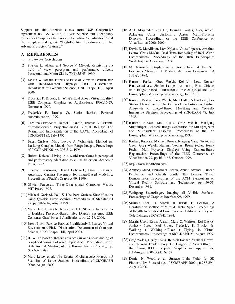
Figure�5.�The�prototype.� (a)�The� synthetic� scene�model,�(b)�the�display�surface�model,�(c)�a�rough�physical�arrangement�of� the� display� surface� model,� (d)� verification� of� physical�model� using� wireframes� projected� from� the� projectors,� (e)�the�final�result�with�perspectively-correct�imagery�generated�in� real-time,� (f)� a� user� is� virtually� spray-painting� on� the�virtual� walls.� (This� figure� is� reproduced� in� color� on� page�000.)�
of� light.� Traditional� methods� for� projecting� multiple� images�“ simultaneously” � on� the� same� surface� include� time-division�and�phase�multiplexing.�Time-division�multiplexing�is�limited�by�the�speed� at� which� one� can� change� projector� images,� and� by� the�decreasing� amount� of� light� corresponding� to� shorter� projection�intervals� as� you�add�more�views.�Phase�multiplexing� (polarized�imagery)� is� limited� by� the� fundamental� ways� you� can� polarize�light,� the� ways� that� projectors� internally� process� the� light�(sometimes� independently� polarizing� it),� and� the� effects� of�polarization� on� the� quality� of� the� final� imagery.� The� ability� to�deliver� independent� imagery� channels� to� each� individual’ s� eyes�is� arguably� a� significant� advantage� that� head-mounted� displays�have� over� projector-based� displays.� We� have� some� ideas� to�address� these� shortcomings,�but�are�not�prepared�to�elaborate�at�this�point.�
4.� PRELIMINARY�RESULTS�We� have� implemented� a� prototype� to� demonstrate� our� ideas.� In�this�prototype,�we�simulate�only�a�part�of�a�synthetic�model�of�a�room� (Figure�5),� because� of� the� limited� space� in� our� research�laboratory— which� is� about� 8.5� ×� 4.5� ×� 2.5� cubic� meters.� We�created� the� physical� display� surfaces� using� construction�Styrofoam� blocks� (Figure�5(c)).� Six� projectors� were� used,� each�
with� an� image� resolution� of� 1024� ×� 768� pixels.� Two� HiBall�trackers�were�used— one�to� track�the�user’ s�head�and�another�to�track� a� virtual� spray� can.� We� used� a� 32-processor,� 8-pipe� SGI�Onyx2�Infinite�Reality2�(“ Reality�Monster” )�to�generate�all�of�the�images�for�the�projectors,�in�real�time.�Due�to�the�limited�number�of�projectors�and�the�relatively�slow�two-pass�rendering,�we�have�not�included�stereo�projections�in�our�system.�
Our� experience� is� that� the� results� were� compelling,� especially�when� looking� through� the�virtual�pass-through�in� the�protruding�wall,�while�walking� from�one� side�of� the�wall� to� the� side.�Also�compelling� is� to� see� the� outside� imagery� move� through� the�window,� passing� behind� the� mullions,� while� the� window� frame�and� surrounding� walls� and� counters� remain� fixed� in� the� room�with�the�user.�In�Figure�5(f),�we�show�a�user�doing�virtual�spray-painting� on� the� walls� and� window� frame.� The� purpose� is� to�demonstrate� the� usefulness� of� being� able� to� physically� move�around� virtual� objects— which� gives� the� user� a� natural� way� to�spatially�interact�with�the�scene.�
We� are� in� the� process� of� building-up� the� model� to� include� the�walls� on� the� right� of� the� camera� in� Figure�5(e),� to� provide� a�further�panoramic�(immersive)�effect.�
5.� CONCLUSION�We� are� encouraged� by� the� results� of� our� first� prototype.� The�ability�to�walk�around�corners�of�the�environment�is,�we�believe,�unique.� As� a� next� step,� we� intend� to� try� a� model� acquired� at�Monticello.� This� will� present� a�much�greater� challenge�because�the� furniture� in� the� rooms� contain� many� more� curved� surfaces,�and�are�thus�not�a�good�match�to�our�building�blocks.�We�believe�that�the�transition�to�the�complex�model�will�require�research�on�more�optimal�block�shapes�and�sizes,�as�well�as�automated�fitting�of�the�physical�model�to�the�virtual.�
Since� we� drive� the� projectors,� we� can� potentially� exert� very�precise� control� over� the� lighting� in� the� room.� Furthermore,� we�already� track� the� participant’ s� eyes,� so� we� may� be� able� to�enhance�the�experience�by�removing�user-induced�shadows�using�backup� projectors� as� described� earlier,� and� lighting� the�participant’ s�bodies�while�keeping�the�projected�light�out�of�their�eyes.�
A�more�practical�enhancement� that�we�plan�for� the�next�version�of� the� system� is� the� transition� to� a� cluster� of� PCs.� This� will�enable�us�to�increase�the�number�of�projectors�and�perhaps�scale�the� system�performance.�With� these,�we�also�hope�to�be�able� to�include�stereo�projections�into�our�future�prototype.�
6.� ACKNOWLEGEMENTS�We� wish� to� thank� Ron� Ardres� and� Reddi-Form,� Inc.� for� their�generous�donation�of�Styrofoam�building�forms�(blocks),�as�well�as� Herman� Towles,� Jim� Mahaney,� David� Harrison,� and� John�Thomas�for�their�local�technical�assistance.�Although�not�actually�incorporated� into� our� demonstrations� yet,� the� Monticello� laser�data� set� mentioned� throughout� was� collected� in� collaboration�with� Prof.� Lars� Nyland� at� UNC-Chapel� Hill,� and� Prof.� David�Luebke� at� the� University� of� Virginia.� Adrian� Ilie� has�implemented�part�of� the� system�and�helped�in�shooting�some�of�the�photographs�that�appear�in�this�paper.�
Support� for� this� research� comes� from� NSF� Cooperative�Agreement� no.� ASC-8920219:� “ NSF� Science� and� Technology�Center�for�Computer�Graphics�and�Scientific�Visualization,” �and�the� supplemental� grant� “ High-Fidelity� Tele-Immersion� for�Advanced�Surgical�Training.” �
7.� REFERENCES�[1]� http://www.3rdtech.com�
[2]� Patricia� L.� Alfano� and� George� F.� Michel.� Restricting� the�field� of� view:� perceptual� and� performance� effects.�Perceptual�and�Motor�Skills,�70(1):35-45,�1990.��
[3]� Kelvin�W.�Arthur.�Effects�of�Field�of�View�on�Performance�with� Head-Mounted� Displays.� Ph.D.� Dissertation,�Department� of� Computer�Science,�UNC�Chapel�Hill,�April�2000.�
[4]� Frederick�P.�Brooks,�Jr.�What’ s�Real�About�Virtual�Reality?�IEEE� Computer� Graphics� &� Applications,� 19(6):16-27,�November�1999.�
[5]� Frederick� P.� Brooks,� Jr.� Static� Haptics.� Personal�communication,�1999.�
[6]� Carolina�Cruz-Neira,�Daniel�J.�Sandin,�Thomas�A.�DeFanti.�Surround-Screen� Projection-Based� Virtual� Reality:� The�Design� and� Implementation� of� the� CAVE.� Proceedings� of�SIGGRAPH�93,�July�1993.�
[7]� Brian� Curless,� Marc� Levoy.� A� Volumetric� Method� for�Building�Complex�Models�from�Range�Images.�Proceedings�of�SIGGRAPH�96,�pp.�303-312,�1996.�
[8]� Hubert� Dolezal.� Living� in� a� world� transformed:� perceptual�and� performatory� adaptation� to�visual�distortion.�Academic�Press,�1982.��
[9]� Shachar� Fleishman,� Daniel� Cohen-Or,� Dani� Lischinski.�Automatic� Camera� Placement� for� Image-Based� Modeling.�Proceedings�of�Pacific�Graphics�99,�1999.�
[10]�Olivier� Faugeras.� Three-Dimensional� Computer� Vision.�MIT�Press,�1993.�
[11]�Michael� Garland,� Paul� S.�Heckbert.�Surface�Simplification�using� Quadric� Error� Metrics.� Proceedings� of� SIGGRAPH�97,�pp.�209-216,�August�1997.�
[12]�Mark�Hereld,�Ivan�R.�Judson,�Rick�L.�Stevens.�Introduction�to� Building� Projector-Based� Tiled� Display� Systems.� IEEE�Computer�Graphics�and�Applications,�pp.�22-28,�2000.�
[13]�Brent�Insko.�Passive�Haptics�Significantly�Enhances�Virtual�Environments.�Ph.D.�Dissertation,�Department�of�Computer�Science,�UNC�Chapel�Hill,�April�2001.�
[14]�H.�W.�Leibowitz.�Recent� advances� in�our�understanding�of�peripheral�vision�and�some�implications.�Proceedings�of�the�30th� Annual� Meeting� of� the� Human� Factors� Society,� pp.�605-607,�1986.��
[15]�Marc� Levoy� et� al.� The� Digital� Michelangelo� Project:� 3D�Scanning� of� Large� Statues.� Proceedings� of� SIGGRAPH�2000,�August�2000.�
[16]�Aditi� Majumder,� Zhu� He,� Herman� Towles,� Greg� Welch.�Achieving� Color� Uniformity� Across� Multi-Projector�Displays.� Proceedings� of� the� IEEE� Conference� on�Visualization�2000,�2000.�
[17]�David�K.�McAllister,�Lars�Nyland,�Voicu�Popescu,�Anselmo�Lastra,� Chris� McCue.�Real-Time�Rendering�of�Real�World�Environments.� Proceedings� of� the� 10th� Eurographics�Workshop�on�Rendering,�1999.�
[18]�M.� Naimark.� Displacements.� An� exhibit� at� the� San�Francisco� Museum� of� Modern� Art,� San� Francisco,� CA�(USA),�1984.�
[19]�Ramesh� Raskar,� Greg� Welch,� Kok-Lim� Low,� Deepak�Bandyopadhyay.� Shader� Lamps:� Animating� Real� Objects�with� Imaged-Based� Illuminations.� Proceedings� of� the� 12th�Eurographics�Workshop�on�Rendering,�June�2001.�
[20]�Ramesh�Raskar,�Greg�Welch,�Matt�Cutts,�Adam�Lake,�Lev�Stesin,� Henry� Fuchs.� The� Office� of� the� Future:� A� Unified�Approach� to� Imaged-Based� Modeling� and� Spatially�Immersive� Displays.� Proceedings� of� SIGGRAPH� 98,� July�1998.�
[21]�Ramesh� Raskar,� Matt� Cutts,� Greg� Welch,� Wolfgang�Stuerzlinger.� Efficient� Image�Generation� for�Multiprojector�and� Multisurface� Displays.� Proceedings� of� the� 9th�Eurographics�Workshop�on�Rendering,�1998.�
[22]�Raskar,�Ramesh,�Michael�Brown,�Ruigang�Yang,�Wei-Chao�Chen,� Greg� Welch,� Herman� Towles,� Brent� Seales,� Henry�Fuchs.� Mutli-Projector� Displays� Using� Camera-Based�Registration.� Proceedings� of� the� IEEE� Conference� on�Visualization�99,�pp.161-168,�October�1999.�
[23]�http://www.reddiform.com/�
[24]�Anthony�Steed,�Emmanuel�Frécon,�Anneli�Avatare,�Duncan�Pemberton� and� Gareth� Smith.� The� London� Travel�Demonstrator.� Proceedings� of� the� ACM� Symposium� on�Virtual� Reality� Software� and� Technology,� pp.� 50-57,�December�1999.�
[25]�Wolfgang� Stuerzlinger.� Imaging� all� Visible� Surfaces.�Proceedings�of�Graphics�Interface�99,�1999.�
[26]�Susuma� Tachi,� T.� Maeda,� R.� Hirata,� H.� Hoshion.� A�Construction� Method� of� Virtual� Haptic�Space.�Proceedings�of�the�4th�International�Conference�on�Artificial�Reality�and�Tele-Existence�(ICAT'94),�1994.�
[27]�Martin�Usoh,�Kevin�Arthur,�Mary�C.�Whitton,�Rui�Bastos,�Anthony� Steed,� Mel� Slater,� Frederick� P.� Brooks,� Jr.�Walking� >� Walking-in-Place� >� Flying,� in� Virtual�Environments.�Proceedings�of�SIGGRAPH�99,�August�1999.�
[28]�Greg�Welch,�Henry�Fuchs,�Ramesh�Raskar,�Michael�Brown,�and� Herman� Towles.� Projected� Imagery� In� Your� Office� in�the� Future,� IEEE� Computer� Graphics� and� Applications,�July/August�2000�20(4):�62-67.�
[29]�Daniel� N.� Wood� et� al.� Surface� Light� Fields� for� 3D�Photography.�Proceedings�of�SIGGRAPH�2000,�pp.287-296,�August�2000.�
Related Documents